JP7143780B2 - Ranging device and ranging method - Google Patents
Ranging device and ranging method Download PDFInfo
- Publication number
- JP7143780B2 JP7143780B2 JP2019027168A JP2019027168A JP7143780B2 JP 7143780 B2 JP7143780 B2 JP 7143780B2 JP 2019027168 A JP2019027168 A JP 2019027168A JP 2019027168 A JP2019027168 A JP 2019027168A JP 7143780 B2 JP7143780 B2 JP 7143780B2
- Authority
- JP
- Japan
- Prior art keywords
- distance
- light
- signal
- time
- mirror
- Prior art date
- Legal status (The legal status is an assumption and is not a legal conclusion. Google has not performed a legal analysis and makes no representation as to the accuracy of the status listed.)
- Active
Links
Images


Classifications
-
- G—PHYSICS
- G01—MEASURING; TESTING
- G01S—RADIO DIRECTION-FINDING; RADIO NAVIGATION; DETERMINING DISTANCE OR VELOCITY BY USE OF RADIO WAVES; LOCATING OR PRESENCE-DETECTING BY USE OF THE REFLECTION OR RERADIATION OF RADIO WAVES; ANALOGOUS ARRANGEMENTS USING OTHER WAVES
- G01S7/00—Details of systems according to groups G01S13/00, G01S15/00, G01S17/00
- G01S7/48—Details of systems according to groups G01S13/00, G01S15/00, G01S17/00 of systems according to group G01S17/00
- G01S7/491—Details of non-pulse systems
- G01S7/4912—Receivers
- G01S7/4915—Time delay measurement, e.g. operational details for pixel components; Phase measurement
-
- G—PHYSICS
- G01—MEASURING; TESTING
- G01C—MEASURING DISTANCES, LEVELS OR BEARINGS; SURVEYING; NAVIGATION; GYROSCOPIC INSTRUMENTS; PHOTOGRAMMETRY OR VIDEOGRAMMETRY
- G01C3/00—Measuring distances in line of sight; Optical rangefinders
- G01C3/02—Details
- G01C3/06—Use of electric means to obtain final indication
-
- G—PHYSICS
- G01—MEASURING; TESTING
- G01S—RADIO DIRECTION-FINDING; RADIO NAVIGATION; DETERMINING DISTANCE OR VELOCITY BY USE OF RADIO WAVES; LOCATING OR PRESENCE-DETECTING BY USE OF THE REFLECTION OR RERADIATION OF RADIO WAVES; ANALOGOUS ARRANGEMENTS USING OTHER WAVES
- G01S17/00—Systems using the reflection or reradiation of electromagnetic waves other than radio waves, e.g. lidar systems
- G01S17/02—Systems using the reflection of electromagnetic waves other than radio waves
- G01S17/06—Systems determining position data of a target
- G01S17/08—Systems determining position data of a target for measuring distance only
- G01S17/32—Systems determining position data of a target for measuring distance only using transmission of continuous waves, whether amplitude-, frequency-, or phase-modulated, or unmodulated
-
- G—PHYSICS
- G01—MEASURING; TESTING
- G01S—RADIO DIRECTION-FINDING; RADIO NAVIGATION; DETERMINING DISTANCE OR VELOCITY BY USE OF RADIO WAVES; LOCATING OR PRESENCE-DETECTING BY USE OF THE REFLECTION OR RERADIATION OF RADIO WAVES; ANALOGOUS ARRANGEMENTS USING OTHER WAVES
- G01S17/00—Systems using the reflection or reradiation of electromagnetic waves other than radio waves, e.g. lidar systems
- G01S17/02—Systems using the reflection of electromagnetic waves other than radio waves
- G01S17/06—Systems determining position data of a target
- G01S17/42—Simultaneous measurement of distance and other co-ordinates
-
- G—PHYSICS
- G01—MEASURING; TESTING
- G01S—RADIO DIRECTION-FINDING; RADIO NAVIGATION; DETERMINING DISTANCE OR VELOCITY BY USE OF RADIO WAVES; LOCATING OR PRESENCE-DETECTING BY USE OF THE REFLECTION OR RERADIATION OF RADIO WAVES; ANALOGOUS ARRANGEMENTS USING OTHER WAVES
- G01S7/00—Details of systems according to groups G01S13/00, G01S15/00, G01S17/00
- G01S7/48—Details of systems according to groups G01S13/00, G01S15/00, G01S17/00 of systems according to group G01S17/00
- G01S7/481—Constructional features, e.g. arrangements of optical elements
- G01S7/4817—Constructional features, e.g. arrangements of optical elements relating to scanning
-
- G—PHYSICS
- G01—MEASURING; TESTING
- G01S—RADIO DIRECTION-FINDING; RADIO NAVIGATION; DETERMINING DISTANCE OR VELOCITY BY USE OF RADIO WAVES; LOCATING OR PRESENCE-DETECTING BY USE OF THE REFLECTION OR RERADIATION OF RADIO WAVES; ANALOGOUS ARRANGEMENTS USING OTHER WAVES
- G01S7/00—Details of systems according to groups G01S13/00, G01S15/00, G01S17/00
- G01S7/48—Details of systems according to groups G01S13/00, G01S15/00, G01S17/00 of systems according to group G01S17/00
- G01S7/497—Means for monitoring or calibrating
Description
本発明は、測距装置および測距方法に関し、特に、飛行時間方式の測距技術に関する。 The present invention relates to a ranging device and a ranging method, and more particularly to a time-of-flight ranging technique.
従来から、物体との距離を測定する技術としてTOF(Time of Flight:飛行時間)方式が知られている。TOF方式の測距処理では、レーザを発光させて、そのレーザ光が物体に反射して戻るまでの飛行時間を測定し、光速を乗じることで物体との距離を導出する(非特許文献1参照)。 Conventionally, a TOF (Time of Flight) method is known as a technique for measuring a distance to an object. In TOF distance measurement processing, a laser beam is emitted, the time of flight for the laser beam to reflect off an object and return is measured, and the distance to the object is derived by multiplying the speed of light (see Non-Patent Document 1). ).
TOF方式の測距技術の具体例として、非特許文献2は、地表を掘削することなく下水道管などの管路を構築する工事に用いる地下の掘削機の位置を、TOF方式で計測する測距装置を開示している。 As a specific example of the TOF distance measurement technology, Non-Patent Document 2 discloses distance measurement that measures the position of an underground excavator used for constructing a pipeline such as a sewage pipe without excavating the ground surface by the TOF method. Apparatus is disclosed.
また、非特許文献1および2に記載された技術では、時間を測定する基準となる参照信号と、測距対象の物体の表面を反射して戻ってきた光を光電変換した検出信号との2つの信号の時間差を測定する必要がある。例えば、2チャネルを持つアナログ-ディジタル変換器(ADC)を用いてこれら2つの信号が取り込まれる。このとき、2つの信号の時間差がΔtだとすると、物体までの距離の測定値Lは、cΔt/2と表される。ここで、cは光速である。
In addition, in the techniques described in
このような従来の測距装置では、ADCのチャネル間のタイミング差(skew)が時間変動する場合に、正確な測距ができなくなるという問題があった。つまり、ADCのチャネル間の信号取得時間にずれ(skew)がある場合は、距離の測定値Lはそれに応じて変動する。例えば、参照信号に対して検出信号がADCのチャネル間スキューによってδtだけ遅れた場合、物体までの距離の測定値L’はc(Δt+δt)/2となり、cδt/2だけ異なる。 Such a conventional distance measuring apparatus has a problem that accurate distance measurement cannot be performed when the timing difference (skew) between ADC channels varies with time. That is, if there is skew in signal acquisition time between channels of the ADC, the distance measurement L will vary accordingly. For example, if the detected signal is delayed relative to the reference signal by .delta.t due to inter-channel skew of the ADC, the measured value L' of the distance to the object will be c(.DELTA.t+.delta.t)/2, differing by c.delta.t/2.
この場合は、スキューδtが固定値であれば、予めスキューδtを測定しておき、距離の測定時に、参照信号と検出信号との時間差から、予め測定されたスキューδtを引けば、正しい距離が得られる。しかし、スキューδtが、信号の取得ごとに異なる場合は、信号の取得ごとに距離の測定値が異なることとなり、得られた距離の精度が悪くなるという問題がある。 In this case, if the skew .delta.t is a fixed value, the skew .delta.t is measured in advance, and when the distance is measured, the skew .delta.t measured in advance is subtracted from the time difference between the reference signal and the detection signal. can get. However, if the skew δt is different for each signal acquisition, the distance measurement value will be different for each signal acquisition, and there is a problem that the accuracy of the obtained distance is degraded.
本発明は、上述した課題を解決するためになされたものであり、ADCのチャネル間のタイミング差(skew)が信号の取得ごとに変動する場合であっても、物体までの距離を高精度に測定することができる測距装置および測距方法を提供することを目的とする。 SUMMARY OF THE INVENTION The present invention has been made to solve the above-mentioned problems, and it is possible to accurately determine the distance to an object even when the timing difference (skew) between ADC channels varies with each signal acquisition. It is an object of the present invention to provide a distance measuring device and a distance measuring method capable of measuring.
上述した課題を解決するために、本発明に係る測距装置は、周期的に強度変調された光を出力する光源と、前記光源の光を2つに分岐する光スプリッタと、前記光スプリッタの一方から出力された前記光を偏向して測定対象の物体に向けて出射する光偏向器と、前記光偏向器からみて前記物体側に配置されたミラーと、前記光偏向器から出射された出射光が前記物体および前記ミラーでそれぞれ反射した第1反射光および第2反射光を検出するフォトディテクタとを有する光学系と、前記第1反射光および前記第2反射光を検出するフォトディテクタからのアナログ信号と、前記光偏向器の偏向角度を示すアナログ信号とをディジタル信号に変換するアナログ-ディジタル変換器と、前記光スプリッタから前記光が出力されてから前記第1反射光が前記フォトディテクタで検出されるまでの時間に基づいて、前記物体までの距離を示す第1距離信号を出力する第1測距部と、前記光スプリッタから前記光が出力されてから前記第2反射光が前記フォトディテクタで検出されるまでの時間に基づいて、前記ミラーまでの距離を示す第2距離信号を出力する第2測距部と、前記第1距離信号を前記第2距離信号に基づいて、前記アナログ-ディジタル変換器のチャネル間のタイミング差の時間変動に起因する誤差に関して補正して、前記物体までの距離を示す第3距離信号を出力する距離補正部とを有する信号処理装置とを備える。また、前記ミラーからの反射光が受光される時間範囲が、前記光源の変調の周期より長くてもよい。 In order to solve the above-described problems, a distance measuring apparatus according to the present invention includes a light source that outputs periodically intensity-modulated light, an optical splitter that splits the light from the light source into two, and the optical splitter. an optical deflector that deflects the light output from one side and emits the light toward an object to be measured; a mirror that is arranged on the object side when viewed from the optical deflector; and an output emitted from the optical deflector. an optical system having a photodetector for detecting first reflected light and second reflected light reflected by the object and the mirror, respectively; and an analog signal from the photodetector for detecting the first reflected light and the second reflected light. and an analog-to-digital converter for converting an analog signal indicating the deflection angle of the optical deflector into a digital signal, and the first reflected light is detected by the photodetector after the light is output from the optical splitter. a first distance measuring unit that outputs a first distance signal indicating the distance to the object based on the time until the second reflected light is detected by the photodetector after the light is output from the optical splitter; a second distance measuring unit that outputs a second distance signal indicating the distance to the mirror based on the time until and a signal processing device having a distance correction unit that corrects an error due to time variation in the timing difference between the channels and outputs a third distance signal indicating the distance to the object. Also, the time range in which the reflected light from the mirror is received may be longer than the period of modulation of the light source.
また、本発明に係る測距装置において、前記ミラーは、前記光偏向器と前記物体とを結んだ線上とは異なる位置に配置されていてもよい。 Moreover, in the distance measuring device according to the present invention, the mirror may be arranged at a position different from a line connecting the optical deflector and the object.
また、本発明に係る測距装置において、前記距離補正部は、前記第1距離信号から前記第2距離信号を引いた値を含む情報を、前記物体までの距離を示す前記第3距離信号として出力してもよい。 Further, in the distance measuring device according to the present invention, the distance correcting unit uses information including a value obtained by subtracting the second distance signal from the first distance signal as the third distance signal indicating the distance to the object. can be output.
また、本発明に係る測距装置において、前記第1測距部は、求めた前記第1距離信号の各々に対応する時刻情報を取得し、前記信号処理装置は、前記第1測距部によって取得された前記時刻情報を前記光偏向器による偏向角度の情報に変換し、偏向角度と距離とが対応付けられた角度-距離信号を出力する時間-角度変換部を備えていてもよい。 Further, in the distance measuring device according to the present invention, the first distance measuring unit acquires time information corresponding to each of the obtained first distance signals, and the signal processing device causes the first distance measuring unit to A time-angle conversion unit may be provided which converts the acquired time information into deflection angle information by the optical deflector and outputs an angle-distance signal in which the deflection angle and the distance are associated.
また、本発明に係る測距装置において、前記第1測距部は、前記光源の光強度のピーク時刻で、前記物体までの距離を示す前記第1距離信号を離散的に取得してもよい。 Further, in the distance measuring device according to the present invention, the first distance measuring section may discretely acquire the first distance signal indicating the distance to the object at the peak time of the light intensity of the light source. .
また、本発明に係る測距装置において、前記第1測距部が取得した、離散的な前記物体までの距離を示す前記第1距離信号に基づいて、前記第3距離信号の補間を行う補間部を備えていてもよい。 Further, in the distance measuring device according to the present invention, interpolation for interpolating the third distance signal based on the first distance signal indicating the discrete distance to the object acquired by the first distance measuring unit. You may have a part.
また、本発明に係る測距装置において、前記光源は、波長が時間と共に変化する波長掃引光源であり、前記光偏向器は、回折格子またはプリズムを含んでいてもよい。 Moreover, in the distance measuring device according to the present invention, the light source may be a wavelength swept light source whose wavelength changes with time, and the optical deflector may include a diffraction grating or a prism.
上述した課題を解決するために、本発明に係る測距方法は、周期的に強度変調された光を光源から出力する第1ステップと、前記光源の光を光スプリッタによって2つに分岐する第2ステップと、前記第2ステップで前記光スプリッタの一方から出力された前記光を光偏向器によって偏向して測定対象の物体に向けて出射する第3ステップと、
前記第3ステップで前記光偏向器から出射された出射光が前記物体および前記光偏向器からみて前記物体側に配置されたミラーでそれぞれ反射した第1反射光および第2反射光をフォトディテクタで検出する第4ステップと、前記第1反射光および前記第2反射光を検出するフォトディテクタからのアナログ信号と前記光偏向器の偏向角度を示すアナログ信号とをアナログ-ディジタル変換器でディジタル信号に変換する第5ステップと、前記第2ステップで前記光スプリッタから前記光が出力されてから前記第1反射光が前記フォトディテクタで検出されるまでの時間に基づいて、前記物体までの距離を示す第1距離信号を出力する第6ステップと、前記第2ステップで前記光スプリッタから前記光が出力されてから前記第2反射光が前記フォトディテクタで検出されるまでの時間に基づいて、前記ミラーまでの距離を示す第2距離信号を出力する第7ステップと、前記第1距離信号を前記第2距離信号に基づいて、前記アナログ-ディジタル変換器のチャネル間のタイミング差の時間変動に起因する誤差に関して補正して、前記物体までの距離を示す第3距離信号を出力する第8ステップとを備える。また、前記ミラーからの反射光が受光される時間範囲が、前記光源の変調の周期より長くてもよい。
In order to solve the above-described problems, the distance measuring method according to the present invention includes a first step of outputting periodically intensity-modulated light from a light source; 2 step, and a third step of deflecting the light output from one of the optical splitters in the second step by an optical deflector and emitting the light toward an object to be measured;
A photodetector detects the first reflected light and the second reflected light, which are the light emitted from the optical deflector in the third step and are reflected by the mirror arranged on the object side as seen from the object and the optical deflector, respectively. and converting an analog signal from a photodetector for detecting the first reflected light and the second reflected light and an analog signal indicating the deflection angle of the optical deflector into a digital signal by an analog-digital converter. a fifth step; and a first distance indicating the distance to the object based on the time from when the light is output from the optical splitter in the second step until the first reflected light is detected by the photodetector. a sixth step of outputting a signal; and determining the distance to the mirror based on the time from when the light is output from the optical splitter in the second step to when the second reflected light is detected by the photodetector. and correcting the first distance signal based on the second distance signal for errors due to time variations in timing differences between the channels of the analog-to-digital converter. and an eighth step of outputting a third distance signal indicating the distance to the object. Also, the time range in which the reflected light from the mirror is received may be longer than the period of modulation of the light source.
本発明によれば、光源からみて物体側に配置されたミラーまでの距離を示す第2距離信号用いて物体までの距離を示す第1距離信号を補正するので、ADCのチャネル間の時間差(skew)が信号の取得ごとに変動する場合であっても、物体までの距離を高精度に測定することができる。 According to the present invention, the first distance signal indicating the distance to the object is corrected using the second distance signal indicating the distance to the mirror arranged on the object side as viewed from the light source. ) varies with each signal acquisition, the distance to the object can be measured with high accuracy.
以下、本発明の好適な実施の形態について、図1から図9Bを参照して詳細に説明する。 Preferred embodiments of the present invention will now be described in detail with reference to FIGS. 1 to 9B.
図1は、本発明の実施の形態に係る測距装置1の構成を示すブロック図である。本実施の形態に係る測距装置1は、図1に示すように、TOF方式により、測距装置1から物体104までの距離を測定する。より詳細には、測距装置1は、光源100から光が出射されてから、測距対象の物体104の表面を反射した反射光が受光されるまでの飛行時間を測定し、測距装置1から物体104までの距離を求める。
FIG. 1 is a block diagram showing the configuration of a
図1に示すように、測距装置1は、光源100、カプラ101、サーキュレータ102、光偏向器103、補正用ミラー(ミラー)105、フォトディテクタ(以下、「PDr」という。)106、フォトディテクタ(以下、「PDs」という。)107、アナログ-ディジタル変換器(ADC)108、および信号処理装置109を備える。カプラ101は光を分岐(スプリット)する光分岐器(スプリッタ)として使用するものである。
As shown in FIG. 1, the
光源100、カプラ101、サーキュレータ102、光偏向器103、補正用ミラー105、PDr106、およびPDs107は、測距装置1が備える光学系を構成する。
光源100は、周期的に強度変調された光を物体104に向けて出射する。具体的には、光源100は、正弦波やパルス信号などの周期的に強度変調された光を発生させる。光源100から出射される光は後述の光偏向器103に入射される。
カプラ101は、光源100から出射された光を参照光路と物体光路とに分ける。カプラ101によって分けられた光の一方は、参照光路上のPDr106に入力され、他方の光は物体光路上のサーキュレータ102および光偏向器103を介して物体104および補正用ミラー105に照射される。
PDr106は、光源100から出力された光を検出し、アナログ信号である第1参照信号r1に変換する。得られた第1参照信号r1は、ADC108のチャネル1(CH1)に入力される。
The
サーキュレータ102は、光路上で互いに反対方向に進む光を分離する。より詳細には、サーキュレータ102は、カプラ101から出射され物体104および補正用ミラー105に照射される光と、物体104および補正用ミラー105を反射して戻ってきた光とを分離する。
The
光偏向器103は、光源100から入射される光の光軸を偏向して出射する。より詳細には、光偏向器103は、光源100から出射され、カプラ101およびサーキュレータ102を介して入射される光を偏向して出射する。以下、光偏向器103が入射される光の光軸を変化させて出射することを「光を偏向する」ということとする。
The
光偏向器103は、予め設定された偏向角度の範囲で光源100からの光を偏向する。光偏向器103としては、例えば、ガルバノミラー、ポリゴンミラー、KTN(タンタル酸ニオブ酸カリウム)結晶を用いた偏向器を用いることができる。光偏向器103による偏向角度は、ミラーの設計や光偏向器103が備える図示されない駆動装置による制御により所望の偏向角度の範囲となるように設定することができる。
The
光偏向器103は、光源100からの光を偏向して出射することによって、物体104および補正用ミラー105ならびのその周辺の空間をスキャン(空間的に掃引、つまり、偏向)して、測距対象の物体104の表面および補正用ミラー105で反射させる。光偏向器103が、光源100からの光を設定された偏向角度の範囲内で出射した光でスキャンする毎に、物体104からの反射光(第1反射光)および補正用ミラー105からの反射光(第2反射光)のそれぞれが後述のPDs107で検出される。
The
補正用ミラー105は、図1に示すように、光偏向器103からみて物体104側に配置される。具体的には、補正用ミラー105は、物体104と光偏向器103とを結ぶ線上とは異なる位置に配置される。例えば、補正用ミラー105は、光偏向器103の偏向する範囲の端付近に設置することができる。より好適には、補正用ミラー105を、光偏向器103の偏向する範囲の端の位置に配置することで、偏向する範囲の大部分を物体104の測定用に利用することができる。
The correcting
PDs107は、物体104や補正用ミラー105からの反射光をサーキュレータ102を介して検出し、アナログ信号の第1検出信号s1に変換する。得られた第1検出信号s1は、ADC108のチャネル2(CH2)に入力される。
The
ADC108は、3つのチャネルを備え、アナログの入力信号をディジタル信号に変換して出力する。ADC108がチャネルごとに変換して出力するディジタル信号は、信号処理装置109に入力される。チャネルCH1に入力されたアナログの第1参照信号r1は、ディジタルの第2参照信号r2に変換され、後述の測距部110に入力される。チャネルCH2に入力された第1検出信号s1についても、ディジタルの第2検出信号s2に変換され、測距部110に入力される。また、チャネルCH3には、光偏向器103の偏向角度を示すアナログ信号である第1角度信号θ1が入力され、ディジタルの第2角度信号θ2に変換されて、後述の時間-角度変換部113に入力される。
The
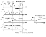
図2の(a)、(b)、および(c)は、ADC108の各チャネルから出力されるディジタル信号の波形の一例を示している。なお、図2では、光源100から出力される光は、正弦波で強度変調されている場合を示している。図2の(a)は、ADC108でディジタル化した第2検出信号s2(CH2)の強度と時間との関係を示している。図2の(b)は、ADC108でディジタル化した第2参照信号r2(CH1)の強度と時間との関係を示している。光偏向器103が出射光を偏向してスキャンする周期は、図2に示すように、Tswと表している。
(a), (b), and (c) of FIG. 2 show an example of the waveform of the digital signal output from each channel of the
図2の(c)は、ADC108でディジタル化した第2角度信号θ2(CH3)の強度と時間との関係を示している。第2角度信号θ2は偏向角に対応している。光偏向器103によるスキャンの周期(時刻0からTsw)に応じて、偏向角の角度が変化している。
FIG. 2(c) shows the relationship between the intensity of the second angle signal θ2 (CH3) digitized by the
図2の(c)では、説明の簡単のため、時刻Tsw後に即座に時刻0の偏向角に戻ることを想定したものとなっている。しかし、現実にそのような偏向を行うことは難しいことが多いため、時刻Tsw後は時刻0~Tswの偏向角の推移を逆に辿るように偏向角を変化させ、時刻2Tswに偏向角が時刻0と同じとなるような偏向角の推移とすることが考えられる。この場合の周期は2Tswとなる。また、このような場合、図2の(c)は、時刻Tswを中心とした対称形となる。あるいは、即座ではなく、ある一定の時間TBで偏向角を図2の(c)に示される時刻0の角度まで戻す機構とする場合もある。この場合は、周期はTsw+TBとなる。
In FIG. 2(c), for simplicity of explanation, it is assumed that the deflection angle returns to the deflection angle at
図1に示すように、信号処理装置109は、ADC108からのディジタル信号を入力信号として、偏向角ごとの測距装置1から物体104までの距離を算出する。具体的には、カプラ101を起点とした物体104までの距離や、光偏向器103から物体104までの距離(より正確には、光路長)を求めることができる。
As shown in FIG. 1, the
信号処理装置109は、測距部(第1測距部)110、補正用ミラー測距部(第2測距部)111、距離補正部112、時間-角度変換部113、および補間部114を備える。
The
測距部110は、ADC108から出力される第2参照信号r2および第2検出信号s2に基づいて、第2参照信号r2のピークの時刻を取得すると共に、その時刻における測距装置1から物体104までの距離を測距する。光偏向器103によって、1次元的に光が偏向する角度の範囲で測距する場合には、より細かい角度ごとに測距することが考えられる。本実施の形態では、第2参照信号r2のピークごとに測距を行うこととし、ピーク間の距離が必要な場合には、後述の補間部114にて、ピーク位置の距離を使って補間して測距装置1から物体104までのより詳細な距離を求める。
Based on the second reference signal r2 and the second detection signal s2 output from the
第2参照信号r2のピーク数については、光源100の光変調の周期をTmとし、光偏向器103のスキャンの周期を前述したようにTswとすると、ピーク数は約Np=Tsw/Tmと表される。光偏向器103の偏向し始めの時刻を0とし、時刻0の方から数えてn個目のピークの時刻をtnとする。図2の波形に共通に示す破線に対応する位置が、第2参照信号r2のn個目のピークの時刻tnである。この時刻tnから±Tm/2の範囲にある第2検出信号s2のピーク時刻との差がΔtnであったとき(図2の(a))、測距部110は、時刻tnで測定されるカプラ101から物体104までの距離LnをcΔtn/2と計算する。ただし、cは光速である。
Regarding the number of peaks of the second reference signal r2, the number of peaks is about Np = Tsw , where Tm is the light modulation period of the
以下、時刻tnに対応する距離のデータを、特に、補正前の距離信号(第1距離信号)Lnと呼ぶ。このように、測距部110は、光偏向器103が光をスキャンする周期ごとに、物体104からの反射光および補正用ミラー105からの反射光両方に基づいて測距を行う。図2の(d)は、測距部110によって求められた補正前の距離信号Lnを示している。
Hereinafter, the distance data corresponding to time t n will be particularly referred to as a pre-correction distance signal (first distance signal) L n . In this manner, the
ここで、図2において、一点鎖線で示した横軸の範囲は、補正用ミラー105の反射光がPDs107で検出される時間範囲を示している。なお、補正用ミラー105の反射光が、光偏向器103が光をスキャンする周期中(時刻0~Tsw)のどこに存在するかについては、事前に求めておく。本実施の形態では、図2に示すように、補正用ミラー105からの反射光の第2検出信号s2が、時刻Tms~Tmeの間にあることが事前にわかっている。特に、図2では、時刻Tmeがスキャン周期の時刻Tswと一致する場合について示している。このような構成を採用することで、本来測距したい時間の範囲が時刻0~Tmsの連続領域となる利点がある。
Here, in FIG. 2, the range of the horizontal axis indicated by the dashed line indicates the time range in which the
なお、本実施の形態ではTme-Tms>Tmであることが少なくとも必要である。これは、時刻Tms~Tmeの間に第2検出信号s2のピークと、第2参照信号r2のピークがそれぞれ1つ以上無ければ、補正用ミラー105までの距離を測距できないからである。図3の(c)ではTme-Tms≒Tmの場合が示されている。さらにTme-Tms≧3Tmであると、補正用ミラー105の位置が正確に測定できるので、より望ましい。
In this embodiment, it is at least required that T me −T ms >T m . This is because the distance to the correcting
Tme-Tms≧3Tmの場合、補正用ミラー105からの反射光から得られる第2検出信号s2のピークは3個となるが、3個の内の端に位置するピークは、ビームの一部が補正用ミラー105から返ってこない(ビームの一部が補正用ミラー105から外れる)影響を受けて強度が減少する。それに対して、3個のうちの真ん中のピークは、ビームの一部が補正用ミラー105から外れる影響を受けにくく、周期Tmでピークがある信号にあたかも単峰性の窓関数をかけた信号形状となる。このような場合、窓関数のピーク付近などの傾きが0に近い部分のピークの位置は、窓関数をかける前のピーク位置とほぼ変わらないが、窓関数の傾きが大きな所にあるピーク程、ピーク位置が元の位置から変化する。
When T me −T ms ≧3T m , the second detection signal s2 obtained from the reflected light from the
したがって、ピークが3個ある場合は、ピーク位置ずれの影響の少ない真ん中のピークを使用することによって、補正用ミラー105の位置を、Tme-Tms<3Tmの場合よりも正確に測定できる。Tmに対してTme-Tmsが大きいほど、ピークの位置ずれの影響は少なくなるので、補正用ミラー105の位置はより正確性を増す。
Therefore, when there are three peaks, the position of the
補正用ミラー測距部111は、カプラ101から光が出射されてから、補正用ミラー105を反射した反射光がPDs107で受光されるまでの時間に基づいて求められる補正用ミラー105までの距離を示す距離信号(第2距離信号)を補正値として出力する。より詳細には、補正用ミラー測距部111は、測距部110で求められた補正前の距離信号Lnのうち、図2の(a)において補正用ミラー105から反射される時間帯Tms~Tmeで測定された第2検出信号s2に基づいて、距離補正部112が使用する補正値Lcorを求める。
The correcting mirror
補正用ミラー測距部111は、例えば、時間帯Tms~Tmeでの補正前の距離信号Lnの平均値を補正値Lcorとしてもよい。あるいは、補正用ミラー測距部111は、時間帯Tms~Tmeの中心時刻(Tms~Tme)/2での補正前の距離信号Lnの値を補正値Lcorとして用いてもよい。
The correcting mirror
あるいは、補正用ミラー測距部111は、補正前の距離信号Lnについて強度減少が生じていない時間帯において取得し、その時間帯での補正前の距離信号Lnの平均値を補正値Lcorとしてもよい。強度変調を生じていない時間帯を取得する方法としては、予め時間帯を選んでおいても良いし、時間帯Tms~Tme内のピーク値を得てから、そのピーク値の一定割合(たとえば90%等)以上の範囲のピークが存在する時間帯としてもよい。
Alternatively, the correcting mirror
距離補正部112は、測距部110が求めた補正前の距離信号Lnを、補正値Lcorに基づいて補正し、補正後の距離信号(第3距離信号)Ln,corを出力する。具体的には、距離補正部112は、補正前の距離信号Lnから補正値Lcorを引き算した結果を補正後の距離信号Ln,corとして出力する。例えば、時刻tnでの補正後の距離信号Ln,corは、Ln-Lcorによって算出される。このような計算によって得られる距離は、補正用ミラー105を距離の基準(0m)とした距離となる。
A
別の例を挙げると、距離補正部112は、補正後の距離信号Ln,corをLn-Lcor+Lmirrorとしてもよい。Lmirrorは、補正用ミラー105の距離として事前に精密に求めてある距離である。補正用ミラー105の距離Lmirrorについては、例えば、予め多くの補正値Lcorを求めておき、その平均値を補正用ミラー105の距離Lmirrorとして用いてもよい。
As another example, the
このような計算による物体104までの距離は、図1に示すように、カプラ101を起点として、カプラ101-PDr106と、カプラ101-PDs107との光路長差に対する距離となる。補正用ミラー105の距離Lmirrorが0mとなる位置に補正用ミラー105を配置すれば、補正値Lcorは0mを中心とした分布を持つので、Ln-Lcorを計算することで、Ln-Lcor+Lmirrorと同じ値が得られる。
As shown in FIG. 1, the distance to the
また、光偏向器103と補正用ミラー105間の距離Ldeflector,mirrorを予め測定しておくなどして事前にわかっていれば、光偏向器103から物体104までの距離は、Ln-Lcor+Ldeflector,mirrorによって求めることができる。
Further, if the distance L deflector,mirror between the
時間-角度変換部113は、測距部110にて取得した第2参照信号r2のピークが出現する時刻、つまり、補正後の距離信号Ln,corに対応する時刻を偏向角に置き換える。例えば、時刻tnでの第2角度信号θ2の強度がξnであるとする。時間-角度変換部113は、第2角度信号θ2の強度ξnを、予め求められている、図2の(e)に示す変換曲線θ(ξ)に代入することにより、強度ξnに対応する偏向角θn=θ(ξn)を得る。そして、時間-角度変換部113は、偏向角θnと補正後の距離信号Ln,corとの対応付けを行った偏向角-距離データ(角度-距離信号)aを出力する。図2の(e)に示す変換曲線は、第2角度信号θ2の強度と偏向角の角度との関係を示している。
The time-
時間-角度変換部113は、第2参照信号r2に含まれる全てのピークの時刻における偏向角を求めて、各偏向角に対応する補正後の距離のデータを出力する。
The time-
補間部114は、第2参照信号r2のピーク間に含まれる偏向角度(時刻)における偏向角と補正後の距離信号Ln,corとが対応付けられた偏向角-距離データを補間により求める。補間部114は、第2参照信号r2のピークとピークとの間に含まれる、より詳細な偏向角(時刻)に対する距離のデータを補間後の偏向角-距離データbとして出力する。このように、補間部114を設けることにより、時間的(角度的)により密な距離を示すデータを求めることができる。
The
[信号処理装置のハードウェア構成]
次に、上述した機能を有する信号処理装置109のハードウェア構成の一例について図3を参照して説明する。
[Hardware Configuration of Signal Processing Device]
Next, an example of the hardware configuration of the
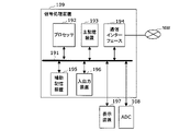
図3に示すように、信号処理装置109は、例えば、バス191を介して接続されるプロセッサ192、主記憶装置193、通信インターフェース194、補助記憶装置195、入出力装置196を備えるコンピュータと、これらのハードウェア資源を制御するプログラムによって実現することができる。信号処理装置109は、例えば、表示装置197がバス191を介して接続され、表示画面に補間後の偏向角-距離データなどを表示してもよい。また、ADC108や測距装置1の光学系が、バス191や入出力装置196を介して接続されている。
As shown in FIG. 3, the
主記憶装置193は、例えば、SRAM、DRAM、およびROMなどの半導体メモリによって実現される。主記憶装置193には、プロセッサ192が各種制御や演算を行うためのプログラムが予め格納されている。プロセッサ192と主記憶装置193とによって、図1に示した測距部110、補正用ミラー測距部111、距離補正部112、時間-角度変換部113、および補間部114を含む信号処理装置109の各機能が実現される。また、プロセッサ192と主記憶装置193とによって、光学系やADC108の設定や制御を行うことができる。
The
通信インターフェース194は、通信ネットワークNWを介して各種外部電子機器との通信を行うためのインターフェース回路である。信号処理装置109は、通信インターフェース194を介して、例えば外部に補間後の偏向角-距離データなどを送出してもよい。
The
通信インターフェース194としては、例えば、LTE、3G、無線LAN、Bluetooth(登録商標)などの無線データ通信規格に対応したインターフェースおよびアンテナが用いられる。通信ネットワークNWは、例えば、WAN(Wide Area Network)やLAN(Local Area Network)、インターネット、専用回線、無線基地局、プロバイダなどを含む。
As the
補助記憶装置195は、読み書き可能な記憶媒体と、その記憶媒体に対してプログラムやデータなどの各種情報を読み書きするための駆動装置とで構成されている。補助記憶装置195には、記憶媒体としてハードディスクやフラッシュメモリなどの半導体メモリを使用することができる。
The
補助記憶装置195は、信号処理装置109が測距処理、補正処理、変換処理、および補間処理を行うためのプログラムを格納するプログラム格納領域を有する。さらには、補助記憶装置195は、例えば、上述したデータやプログラムやなどをバックアップするためのバックアップ領域などを有していてもよい。
The
補助記憶装置195は、補正用ミラー測距部111が用いる補正用ミラー105からの反射光をPDs107が受光する時間範囲Tms~Tmeに関する情報を記憶している。また、補助記憶装置195は、時間-角度変換部113が変換処理に用いる変換曲線を記憶している。
The
入出力装置196は、表示装置197など外部機器からの信号を入力したり、外部機器へ信号を出力したりするI/O端子により構成される。
The input/
なお、信号処理装置109は、1つのコンピュータによって実現される場合だけでなく、互いに通信ネットワークNWで接続された複数のコンピュータによって分散されていてもよい。また、プロセッサ192は、FPGA(Field-Programmable Gate Array)、LSI(Large Scale Integration)、ASIC(Application Specific Integrated Circuit)等のハードウェアによって実現されていてもよい。
It should be noted that the
[測距装置の動作]
次に、本実施の形態に係る測距装置1の動作について、図4のフローチャートを参照して説明する。
[Range finder operation]
Next, the operation of the
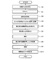
まず、光源100から、周期的な強度変調された光、例えば、正弦波で強度変調された光を出力する(ステップS1)。光源100から出射された光は、カプラ101によって参照光路側と物体光路側とに分けられる。参照光路側の光は、PDr106で受光され、光電変換されて第1参照信号r1が出力される。一方、物体光路側の光は、サーキュレータ102を介して、光偏向器103によって偏向され、物体104の周辺の空間がスキャン周期をTswとして、光でスキャンされる(ステップS2)。
First, the
次に、光偏向器103によって偏向された光が空間内を1回スキャンすると、物体104および補正用ミラー105のそれぞれに光が照射され、反射光が光偏向器103およびサーキュレータ102を介して、PDs107で検出される(ステップS3)。なお、補正用ミラー105は、例えば、最大偏向角の位置に設置することができる。また、光偏向器103が光を偏向する偏向角度を示す第1角度信号θ1は、ADC108のチャネルCH3に入力される。
Next, when the light deflected by the
その後、ADC108は、チャネルCH1、CH2、およびCH3に入力されるアナログ信号をディジタル信号に変換する(ステップS4)。より詳細には、ADC108のチャネルCH1には、アナログの第1参照信号r1が入力され、ディジタルの第2参照信号r2に変換される。ADC108のチャネルCH2には、物体104および補正用ミラー105からの反射光に基づくアナログの第1検出信号s1が入力され、ディジタルの第2検出信号s2に変換される。また、ADC108のチャネルCH3には第1角度信号θ1が入力され、ディジタルの第2角度信号θ2に変換される。
次に、信号処理装置109において、測距部110は、第2参照信号r2および第2検出信号s2に基づいて、補正前の距離信号LnとLnに対応する時刻tnを求める(ステップS5)。より詳細には、測距部110は、図2の(b)における第2参照信号r2の各ピーク時の時刻tnでの測距装置1から物体104までの距離を示す、補正前の距離信号Lnを算出する(図2の(d))。
Next, in the
次に、補正用ミラー測距部111は、測距部110によって求められた距離信号Lnを補正するための補正値Lcorを求める(ステップS6)。具体的には、補正用ミラー測距部111は、図2の(a)に示すように、補正用ミラー105から光が反射される時間帯Tm~Tmeで測定された第2検出信号s2に基づいて、補正値Lcorを算出する。補正用ミラー測距部111は、例えば、時間帯Tm~Tmeでの距離(Ln)の平均値を補正値Lcorとして用いることができる。
Next, the correcting mirror
次に、距離補正部112は、ステップS6で求められた補正値Lcorを用いて、測距部110がステップS5で求めた補正前の距離信号Lnを補正する(ステップS7)。具体的には、距離補正部112は、Ln-Lcorによって、時刻tnでの補正後の距離信号Ln,corを算出する。
Next, the
その後、時間-角度変換部113は、ステップS7で求められた補正後の距離信号Ln,corを変換し、測距部110で求めた第2参照信号r2のピーク時刻、つまり、補正後の距離信号Ln,corに対応する時刻tnを偏向角θnに置き換えた偏向角-距離データaを出力する(ステップS8)。より詳細には、時間-角度変換部113は、予め補助記憶装置195などに記憶されている図2の(e)に示す変換曲線θ(ξ)を読み出して、時刻tnでの第2角度信号θ2の強度ξnを変換曲線θ(ξ)に代入し時刻tnを偏向角θn=θ(ξn)に変換する。さらに、時間-角度変換部113は、偏向角θnと補正後の距離信号Ln,corが対応付けられた偏向角-距離データaを求める。
After that, the time-
次に、補間部114は、ステップS8で求められた偏向角と距離とが対応付けられたデータaに基づいて、第2参照信号r2のピーク間の値を補間する(ステップS9)。その後、補間部114は、補間した偏向角-距離データbを出力する(ステップS10)。
Next, the
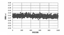
次に、本実施の形態に係る信号処理装置109によって処理された、ある1点の時刻における補正前および補正後の物体104までの距離を図5から図8に示す。
図5および図6は、補正前の物体104までの距離を示しており、図7および図8は、補正後の物体104までの距離を示している。また、図5および図7は、1000回測定を繰り返した場合の各回の物体104までの距離の測定値のプロットである。図6および図8は、距離の測定値をヒストグラムで示している。
Next, FIGS. 5 to 8 show the distances to the
5 and 6 show the distance to the
図5から図8に示す測定例では、ADC108の第1検出信号s1を入力したチャネルCH2と第1参照信号r1を入力したチャネルCH1のスキューの時間変動が2極化しており、その差は、約0.5[ns]であった。そのため、図5および図6に示すように、補正前と補正後の距離の差は、約7.5[cm](=3×108×0.5×10-9/2[m])であった。
In the measurement examples shown in FIGS. 5 to 8, the skew time fluctuations of the channel CH2 to which the first detection signal s1 of the
本実施の形態に係る信号処理装置109による補正処理を行うことによって、図7および図8に示すように、距離の値における2極化がなくなる効果が得られた。なお、標準偏差については、補正前では3.7656[cm]であったものが、補正後は0.8654[cm]となり、補正前の23%程度まで小さくなった。このように、補正処理を行うことで距離の測定精度を改善することができた。
By performing correction processing by the
また、図5において補正前の距離が-0.81[m]~-0.89[m]付近であるのに対し、補正後の距離が-0.45[m]付近にみられるのは、補正用ミラー105の距離Lmirrorが-0.36[m]~-0.44[m]付近に位置することによる。補正用ミラー105による補正値Lcorの1000個の値の平均値は0.44749[m]である。
In addition, in FIG. 5, the distance before correction is around -0.81 [m] to -0.89 [m], while the distance after correction is around -0.45 [m]. , because the distance L mirror of the
この平均値をLmirrorとして、補正後の距離信号をLn-Lcor+Lmirrorを用いて計算すると、図1で説明したカプラ101を起点としてカプラ101-PDr106と、カプラ101-PDs107との光路長差に対する物体104の距離を計算することができる。
Taking this average value as L mirror and calculating the corrected distance signal using L n −L cor +L mirror , the optical path between the
図9Aおよび図9Bは、本実施の形態に係る測距装置1によって物体104の位置を起点から20[cm]~155[cm]までずらしながら、距離を測定した結果である。物体104が設置された位置ごとに100回の測定を行い、補正前および補正後の距離の平均値と標準偏差をそれぞれ求めた。
9A and 9B show the results of measuring the distance while shifting the position of the
図9Aに示す補正前の標準偏差は、3.8[cm]程度であったが、図9Bに示す補正後の標準偏差は1[cm]程度まで小さくなっている。このことから、本実施の形態に係る信号処理装置109による補正処理を行うことによって、距離測定の精度が向上していることがわかる。
The standard deviation before correction shown in FIG. 9A was about 3.8 [cm], but the standard deviation after correction shown in FIG. 9B is reduced to about 1 [cm]. From this, it can be seen that the accuracy of distance measurement is improved by performing correction processing by the
図9Aに示す補正前の物体104までの距離の平均値と、図9Bに示す補正後の距離の平均値とは互いに近い値となっている。これは、図1で説明したカプラ101を起点とした、カプラ101-PDr106と、カプラ101-PDs107との光路長差がほぼ等しい、すなわち、ほぼ0mとなる位置に補正用ミラー105が配置されていることに起因する。
The average value of the distances to the
以上説明したように、本実施の形態に係る測距装置1によれば、補正用ミラー105からの反射光に基づいて補正値Lcorを求め、測距装置1から物体104までの距離信号Lnを補正する。そのため、ADCのチャネル間のタイミング差(skew)が信号の取得ごとに変動する場合であっても、物体までの距離を高精度に測定することができる。
As described above, according to the
また、本実施の形態に係る測距装置1は、参照信号のピーク間の距離データを補間するので、物体までの距離をより高精度に測定することができる。
Further, since the
以上、本発明の測距装置および測距方法における実施の形態について説明したが、本発明は説明した実施の形態に限定されるものではなく、請求項に記載した発明の範囲において当業者が想定し得る各種の変形を行うことが可能である。 Although the embodiments of the distance measuring device and the distance measuring method of the present invention have been described above, the present invention is not limited to the described embodiments, and can be assumed by those skilled in the art within the scope of the invention described in the claims. Various possible modifications can be made.
例えば、説明した実施の形態では、信号処理装置109において、時間-角度変換部113が補正後の距離信号Ln,corを偏向角-距離データaに変換した後に、補間部114が補間処理を行う具体例を説明した。しかし、補間処理は時間-角度変換部113による変換処理の前に実行してもよい。この場合、補間部114は、補正後の距離信号Ln,corに基づいて第2参照信号r2のピーク間の補間を行い、その後、時間-角度変換部113が、時刻を偏向角に変換することになる。
For example, in the embodiment described above, in the
補間処理を時間-角度変換処理の前に行う場合は、時間-角度変換部113で必要となる時刻情報は、測距部110で取得した第2参照信号r2のピーク時刻をそのまま使用できない。なぜなら、測距部110で得られた距離の数(測距部110で得られた時刻の数と等しい)は補間部114から出力される距離の数と異なるからである。そこで、補間部114において、測距部110で取得した第2参照信号r2のピーク時刻を用いて、補間で得た距離情報に対応する時刻を算出し、その時刻を用いて時間-角度変換部113にて時刻を角度に変換する。
When the interpolation process is performed before the time-angle conversion process, the peak time of the second reference signal r2 obtained by the
これまで説明した実施の形態では、光源100から出力される光は、正弦波など周期的に強度変調された光であり、波長掃引された光ではない場合について説明した。しかし、光源100は、周期的な強度変調機能を備えた波長掃引光源であってもよい。この場合、光偏向器103には、透過型や反射型の回折格子や屈折率分散の大きい材料からなるプリズムなどの受動光学素子が用いられる。また、光源100は、周期的な強度変調機能を備えた波長掃引光源であっても、公知の空間光変調器を光偏向器103に用いてもよい。
In the embodiments described so far, the case where the light output from the
この場合、回折格子の格子定数などは、光源100の光の波長や、測定が要求される最大距離、および測距装置1の大きさなどに応じて、所望の角度の範囲で偏向するように設計することができる。また、プリズムの屈折率やその波長分散についても、同様に所望の角度で偏向するように、屈折率やその波長分散を持つ材料を選ぶことができる。また、光源100として周期的な強度変調機能を備えた波長掃引光源を用いる場合、第1角度信号θ1は、光源100から出力される光の波長に連動する構成となる。
In this case, the grating constant of the diffraction grating is determined so that it is deflected within a desired angular range according to the wavelength of the light from the
光源100を周期的な強度変調機能を備えた波長掃引光源として、光偏向器103を回折格子やプリズム等の受動光学素子とする利点は、光偏向器103に機械動作を必要とする部品が必要なくなることである。このことから、たとえば、測距装置1が備える光学系を光偏向器103とそれ以外に分離して、偏向器をプローブ、それ以外を本体として、プローブと本体を光ファイバで接続した場合、プローブを小型化できるので、狭い場所等にも設置したり、あるいは、人が簡単にプローブ部を持ち運ぶなどして、測定ができる。また、プローブには機械動作をする部品がないため、プローブの振動に対する耐性が高くなるので、本体とプローブを離して、本体を振動の緩慢な場所に退避することにより、振動の激しい環境においても正確に測定ができる。
The advantage of using the
1…測距装置、100…光源、101…カプラ、102…サーキュレータ、103…光偏向器、104…物体、105…補正用ミラー、106…フォトディテクタPDr、107…フォトディテクタPDs、108…ADC、109…信号処理装置、110…測距部、111…補正用ミラー測距部、112…距離補正部、113…時間-角度変換部、114…補間部、191…バス、192…プロセッサ、193…主記憶装置、194…通信インターフェース、195…補助記憶装置、196…入出力装置、197…表示装置。
REFERENCE SIGNS
Claims (10)
前記光源の光を2つに分岐する光スプリッタと、 前記光スプリッタの一方から出力された前記光を偏向して測定対象の物体に向けて出射する光偏向器と、
前記光偏向器からみて前記物体側に配置されたミラーと、
前記光偏向器から出射された出射光が前記物体および前記ミラーでそれぞれ反射した第1反射光および第2反射光を検出するフォトディテクタと
を有する光学系と、
前記第1反射光および前記第2反射光を検出するフォトディテクタからのアナログ信号と、前記光偏向器の偏向角度を示すアナログ信号とをディジタル信号に変換するアナログ-ディジタル変換器と、
前記光スプリッタから前記光が出力されてから前記第1反射光が前記フォトディテクタで検出されるまでの時間に基づいて、前記物体までの距離を示す第1距離信号を出力する第1測距部と、
前記光スプリッタから前記光が出力されてから前記第2反射光が前記フォトディテクタで検出されるまでの時間に基づいて、前記ミラーまでの距離を示す第2距離信号を出力する第2測距部と、
前記第1距離信号を前記第2距離信号に基づいて、前記アナログ-ディジタル変換器のチャネル間のタイミング差の時間変動に起因する誤差に関して補正して、前記物体までの距離を示す第3距離信号を出力する距離補正部と
を有する信号処理装置と
を備える測距装置。 a light source that outputs periodically intensity-modulated light;
an optical splitter that splits the light from the light source into two; an optical deflector that deflects the light output from one of the optical splitters and emits the light toward an object to be measured;
a mirror arranged on the object side when viewed from the optical deflector;
a photodetector that detects first reflected light and second reflected light that are reflected by the object and the mirror, respectively, from the light emitted from the optical deflector;
an analog-to-digital converter that converts an analog signal from a photodetector that detects the first reflected light and the second reflected light and an analog signal that indicates the deflection angle of the optical deflector into a digital signal;
a first distance measuring unit configured to output a first distance signal indicating a distance to the object based on the time from when the light is output from the light splitter until when the first reflected light is detected by the photodetector; ,
a second distance measuring unit that outputs a second distance signal indicating the distance to the mirror based on the time from the output of the light from the optical splitter to the detection of the second reflected light by the photodetector; ,
A third distance signal indicating the distance to the object by correcting the first distance signal based on the second distance signal for errors caused by time variations in timing differences between channels of the analog-to-digital converter. A range finder comprising: a distance correction unit that outputs a signal processing device;
前記ミラーからの反射光が受光される時間範囲が、前記光源の変調の周期より長いことを特徴とする測距装置。 A distance measuring device, wherein a time range in which the reflected light from the mirror is received is longer than a period of modulation of the light source.
前記ミラーは、前記光偏向器と前記物体とを結んだ線上とは異なる位置に配置されることを特徴とする測距装置。 In the distance measuring device according to claim 1 or claim 2 ,
A distance measuring device, wherein the mirror is arranged at a position different from a line connecting the optical deflector and the object.
前記距離補正部は、前記第1距離信号から前記第2距離信号を引いた値を含む情報を、前記物体までの距離を示す前記第3距離信号として出力することを特徴とする測距装置。 In the rangefinder according to any one of claims 1 to 3 ,
A distance measuring device, wherein the distance correction unit outputs information including a value obtained by subtracting the second distance signal from the first distance signal as the third distance signal indicating the distance to the object.
前記第1測距部は、求めた前記第1距離信号の各々に対応する時刻情報を取得し、
前記信号処理装置は、
前記第1測距部によって取得された前記時刻情報を前記光偏向器による偏向角度の情報に変換し、偏向角度と距離とが対応付けられた角度-距離信号を出力する時間-角度変換部を備える
ことを特徴とする測距装置。 In the rangefinder according to any one of claims 1 to 4 ,
The first distance measuring unit acquires time information corresponding to each of the obtained first distance signals,
The signal processing device is
a time-angle conversion unit for converting the time information acquired by the first distance measurement unit into information on the deflection angle by the optical deflector and outputting an angle-distance signal in which the deflection angle and the distance are associated; A rangefinder, comprising:
前記第1測距部は、前記光源の光強度のピーク時刻で、前記物体までの距離を示す前記第1距離信号を離散的に取得することを特徴とする測距装置。 In the rangefinder according to any one of claims 1 to 5 ,
The distance measuring device, wherein the first distance measuring section discretely acquires the first distance signal indicating the distance to the object at the peak time of the light intensity of the light source.
前記信号処理装置は、
前記第1測距部が取得した、離散的な前記物体までの距離を示す前記第1距離信号に基づいて、前記第3距離信号の補間を行う補間部を備えることを特徴とする測距装置。 The distance measuring device according to claim 6 ,
The signal processing device is
A distance measuring device, comprising: an interpolating unit that interpolates the third distance signal based on the first distance signal indicating a discrete distance to the object, which is acquired by the first distance measuring unit. .
前記光源は、波長が時間と共に変化する波長掃引光源であり、
前記光偏向器は、回折格子またはプリズムを含む
ことを特徴とする測距装置。 In the rangefinder according to any one of claims 1 to 7 ,
the light source is a wavelength-swept light source whose wavelength varies with time;
A distance measuring device, wherein the optical deflector includes a diffraction grating or a prism.
前記光源の光を光スプリッタによって2つに分岐する第2ステップと、
前記第2ステップで前記光スプリッタの一方から出力された前記光を光偏向器によって偏向して測定対象の物体に向けて出射する第3ステップと、
前記第3ステップで前記光偏向器から出射された出射光が前記物体および前記光偏向器からみて前記物体側に配置されたミラーでそれぞれ反射した第1反射光および第2反射光をフォトディテクタで検出する第4ステップと、
前記第1反射光および前記第2反射光を検出するフォトディテクタからのアナログ信号と前記光偏向器の偏向角度を示すアナログ信号とをアナログ-ディジタル変換器でディジタル信号に変換する第5ステップと、
前記第2ステップで前記光スプリッタから前記光が出力されてから前記第1反射光が前記フォトディテクタで検出されるまでの時間に基づいて、前記物体までの距離を示す第1距離信号を出力する第6ステップと、
前記第2ステップで前記光スプリッタから前記光が出力されてから前記第2反射光が前記フォトディテクタで検出されるまでの時間に基づいて、前記ミラーまでの距離を示す第2距離信号を出力する第7ステップと、
前記第1距離信号を前記第2距離信号に基づいて、前記アナログ-ディジタル変換器のチャネル間のタイミング差の時間変動に起因する誤差に関して補正して、前記物体までの距離を示す第3距離信号を出力する第8ステップと
を備える測距方法。 a first step of outputting periodically intensity-modulated light from a light source;
a second step of splitting the light from the light source into two by an optical splitter;
a third step of deflecting the light output from one of the optical splitters in the second step by an optical deflector and emitting the light toward an object to be measured;
A photodetector detects the first reflected light and the second reflected light, which are the light emitted from the optical deflector in the third step and are reflected by the mirror arranged on the object side as seen from the object and the optical deflector, respectively. a fourth step to
a fifth step of converting an analog signal from a photodetector for detecting the first reflected light and the second reflected light and an analog signal indicating the deflection angle of the optical deflector into digital signals with an analog-to-digital converter;
outputting a first distance signal indicating the distance to the object based on the time from when the light is output from the optical splitter to when the first reflected light is detected by the photodetector in the second step; 6 steps and
outputting a second distance signal indicating the distance to the mirror based on the time from when the light is output from the optical splitter to when the second reflected light is detected by the photodetector in the second step; 7 steps and
A third distance signal indicating the distance to the object by correcting the first distance signal based on the second distance signal for errors caused by time variations in timing differences between channels of the analog-to-digital converter. and an eighth step of outputting .
前記ミラーからの反射光が受光される時間範囲が、前記光源の変調の周期より長いことを特徴とする測距方法。 A distance measuring method, wherein a time range in which the reflected light from the mirror is received is longer than a period of modulation of the light source.
Priority Applications (3)
| Application Number | Priority Date | Filing Date | Title |
|---|---|---|---|
| JP2019027168A JP7143780B2 (en) | 2019-02-19 | 2019-02-19 | Ranging device and ranging method |
| PCT/JP2020/004041 WO2020170796A1 (en) | 2019-02-19 | 2020-02-04 | Rangefinder and rangefinding method |
| US17/420,410 US20220082675A1 (en) | 2019-02-19 | 2020-02-04 | Rangefinder and Rangefinding Method |
Applications Claiming Priority (1)
| Application Number | Priority Date | Filing Date | Title |
|---|---|---|---|
| JP2019027168A JP7143780B2 (en) | 2019-02-19 | 2019-02-19 | Ranging device and ranging method |
Publications (2)
| Publication Number | Publication Date |
|---|---|
| JP2020134285A JP2020134285A (en) | 2020-08-31 |
| JP7143780B2 true JP7143780B2 (en) | 2022-09-29 |
Family
ID=72144640
Family Applications (1)
| Application Number | Title | Priority Date | Filing Date |
|---|---|---|---|
| JP2019027168A Active JP7143780B2 (en) | 2019-02-19 | 2019-02-19 | Ranging device and ranging method |
Country Status (3)
| Country | Link |
|---|---|
| US (1) | US20220082675A1 (en) |
| JP (1) | JP7143780B2 (en) |
| WO (1) | WO2020170796A1 (en) |
Families Citing this family (1)
| Publication number | Priority date | Publication date | Assignee | Title |
|---|---|---|---|---|
| JP7344732B2 (en) * | 2019-09-25 | 2023-09-14 | 株式会社トプコン | Surveying equipment and surveying equipment systems |
Citations (5)
| Publication number | Priority date | Publication date | Assignee | Title |
|---|---|---|---|---|
| JP2015152485A (en) | 2014-02-17 | 2015-08-24 | 株式会社デンソー | Distance measuring apparatus |
| JP2015175629A (en) | 2014-03-13 | 2015-10-05 | 株式会社日立ハイテクノロジーズ | Distance measuring apparatus, and distance measuring system |
| JP2016170053A (en) | 2015-03-13 | 2016-09-23 | オムロンオートモーティブエレクトロニクス株式会社 | Laser radar device |
| US20180040119A1 (en) | 2016-08-03 | 2018-02-08 | Sightline Innovation Inc. | System and method for integrated laser scanning and signal processing |
| JP2018059789A (en) | 2016-10-05 | 2018-04-12 | 国立大学法人東京農工大学 | Distance measuring apparatus and distance measuring method |
Family Cites Families (1)
| Publication number | Priority date | Publication date | Assignee | Title |
|---|---|---|---|---|
| JP3155331B2 (en) * | 1992-04-21 | 2001-04-09 | オリンパス光学工業株式会社 | Distance measuring device |
-
2019
- 2019-02-19 JP JP2019027168A patent/JP7143780B2/en active Active
-
2020
- 2020-02-04 US US17/420,410 patent/US20220082675A1/en active Pending
- 2020-02-04 WO PCT/JP2020/004041 patent/WO2020170796A1/en active Application Filing
Patent Citations (5)
| Publication number | Priority date | Publication date | Assignee | Title |
|---|---|---|---|---|
| JP2015152485A (en) | 2014-02-17 | 2015-08-24 | 株式会社デンソー | Distance measuring apparatus |
| JP2015175629A (en) | 2014-03-13 | 2015-10-05 | 株式会社日立ハイテクノロジーズ | Distance measuring apparatus, and distance measuring system |
| JP2016170053A (en) | 2015-03-13 | 2016-09-23 | オムロンオートモーティブエレクトロニクス株式会社 | Laser radar device |
| US20180040119A1 (en) | 2016-08-03 | 2018-02-08 | Sightline Innovation Inc. | System and method for integrated laser scanning and signal processing |
| JP2018059789A (en) | 2016-10-05 | 2018-04-12 | 国立大学法人東京農工大学 | Distance measuring apparatus and distance measuring method |
Also Published As
| Publication number | Publication date |
|---|---|
| WO2020170796A1 (en) | 2020-08-27 |
| JP2020134285A (en) | 2020-08-31 |
| US20220082675A1 (en) | 2022-03-17 |
Similar Documents
| Publication | Publication Date | Title |
|---|---|---|
| US10330780B2 (en) | LIDAR based 3-D imaging with structured light and integrated illumination and detection | |
| US11550056B2 (en) | Multiple pixel scanning lidar | |
| US8452561B2 (en) | Time delay estimation | |
| JP2019056567A (en) | Distance measuring device | |
| US20220365214A1 (en) | On-chip monitoring and calibration circuits for frequency modulated continuous wave lidar | |
| JP6303026B2 (en) | Measuring method and apparatus | |
| US11054524B2 (en) | Optimizing a lidar system using sub-sweep sampling | |
| JP2015094760A5 (en) | ||
| US9798004B2 (en) | Laser ranging sensors and methods that use a ladder of synthetic waves having increasing wavelengths to calculate a distance measurement | |
| JP7143780B2 (en) | Ranging device and ranging method | |
| CN109946707A (en) | Laser radar reception device, emitter, system and distance measurement method | |
| CN111699442A (en) | Time measurement correction method and device | |
| JP7115375B2 (en) | Ranging device and ranging method | |
| US20210026017A1 (en) | Apparatus for ascertaining a distance to an object | |
| JP7201088B2 (en) | rangefinder | |
| JP2017044565A (en) | Distance measurement device and method | |
| JP2021012136A (en) | Three-dimensional information acquisition device and three-dimensional information acquisition method | |
| WO2019054917A1 (en) | Time-of-flight scheimpflug lidar | |
| US9124060B1 (en) | System and method for generating and utilizing a valid sweep vector to obviate spurious data and increase sweep rate in an akinetic path-based swept laser | |
| US20240004044A1 (en) | Apparatus and method for measuring distant to and/or velocity of physical object | |
| WO2022209309A1 (en) | Device and method for measuring distance and/or speed of object | |
| US9385501B1 (en) | System and method for generating and utilizing a valid sweep signal to obviate spurious data and increase sweep rate in an akinetic path-based swept laser | |
| US9153939B1 (en) | System and method for generating and utilizing sample trigger blanking to obviate spurious data and increase sweep rate in an akinetic path-based swept laser | |
| KR20170052428A (en) | Apparatus and method for measuring path difference in optical interferometer using ofdr | |
| CN116755099A (en) | System and method for measuring speed and distance |
Legal Events
| Date | Code | Title | Description |
|---|---|---|---|
| A621 | Written request for application examination |
Free format text: JAPANESE INTERMEDIATE CODE: A621 Effective date: 20210531 |
|
| A131 | Notification of reasons for refusal |
Free format text: JAPANESE INTERMEDIATE CODE: A131 Effective date: 20211221 |
|
| A521 | Request for written amendment filed |
Free format text: JAPANESE INTERMEDIATE CODE: A523 Effective date: 20220221 |
|
| A131 | Notification of reasons for refusal |
Free format text: JAPANESE INTERMEDIATE CODE: A131 Effective date: 20220524 |
|
| A521 | Request for written amendment filed |
Free format text: JAPANESE INTERMEDIATE CODE: A523 Effective date: 20220613 |
|
| TRDD | Decision of grant or rejection written | ||
| A01 | Written decision to grant a patent or to grant a registration (utility model) |
Free format text: JAPANESE INTERMEDIATE CODE: A01 Effective date: 20220816 |
|
| A61 | First payment of annual fees (during grant procedure) |
Free format text: JAPANESE INTERMEDIATE CODE: A61 Effective date: 20220829 |
|
| R150 | Certificate of patent or registration of utility model |
Ref document number: 7143780 Country of ref document: JP Free format text: JAPANESE INTERMEDIATE CODE: R150 |