JP7143561B2 - fuel tank switchgear - Google Patents

fuel tank switchgear Download PDF

Info

Publication number
JP7143561B2
JP7143561B2 JP2019022208A JP2019022208A JP7143561B2 JP 7143561 B2 JP7143561 B2 JP 7143561B2 JP 2019022208 A JP2019022208 A JP 2019022208A JP 2019022208 A JP2019022208 A JP 2019022208A JP 7143561 B2 JP7143561 B2 JP 7143561B2
Authority
JP
Japan
Prior art keywords
opening
valve
passage
drainage
port
Prior art date
Legal status (The legal status is an assumption and is not a legal conclusion. Google has not performed a legal analysis and makes no representation as to the accuracy of the status listed.)
Active
Application number
JP2019022208A
Other languages
Japanese (ja)
Other versions
JP2020128182A (en
Inventor
智裕 久保
徳彦 石原
哲也 柴▲崎▼
考史 坂本
Current Assignee (The listed assignees may be inaccurate. Google has not performed a legal analysis and makes no representation or warranty as to the accuracy of the list.)
Toyoda Gosei Co Ltd
Original Assignee
Toyoda Gosei Co Ltd
Priority date (The priority date is an assumption and is not a legal conclusion. Google has not performed a legal analysis and makes no representation as to the accuracy of the date listed.)
Filing date
Publication date
Application filed by Toyoda Gosei Co Ltd filed Critical Toyoda Gosei Co Ltd
Priority to JP2019022208A priority Critical patent/JP7143561B2/en
Priority to US16/567,225 priority patent/US10843555B2/en
Priority to CN201910910898.9A priority patent/CN110962587B/en
Publication of JP2020128182A publication Critical patent/JP2020128182A/en
Application granted granted Critical
Publication of JP7143561B2 publication Critical patent/JP7143561B2/en
Active legal-status Critical Current
Anticipated expiration legal-status Critical

Links

Images

Description

本発明は、燃料タンクの開閉装置に関する。 The present invention relates to a fuel tank opening/closing device.

従来の燃料タンクの開閉装置は、特許文献1に記載されているように、燃料通路と装置外部とを連通する排液路に流路を開閉する排液弁を備えている。そして、この特許文献1は、排液路を通常は排液弁により閉鎖することで、外部からの塵等の浸入を防止している。また、燃料通路に雨水などの液体が入り込めば、その入り込んだ液体を、排液弁により排液路を開放することにより、外部に排出している。 2. Description of the Related Art A conventional fuel tank opening/closing device includes a drain valve for opening and closing a drain passage that communicates a fuel passage with the outside of the device, as described in Patent Document 1. In addition, in Patent Document 1, the drainage path is normally closed by a drainage valve, thereby preventing dust and the like from entering from the outside. Also, if liquid such as rainwater enters the fuel passage, the liquid that has entered is discharged to the outside by opening the drainage passage with a drainage valve.

特開2017-114272号公報JP 2017-114272 A

特許文献1に記載された燃料タンクの開閉装置では、排液路の形成部位がアウターボディーから外側に突出しており、その突出部位は、開閉装置が装着される給油室において露出する。排液路を開閉する排液弁は、この突出部位に配設されているので、外部からの影響、例えば給油ノズルの接触に伴う外力の加わりなどを受けやすい。外部からの影響を少なくするには、排液弁を排液路の形成部位内に収納するようにすればよい。しかしながら、開閉装置には、車両の給油室における設置スペースの制約から、省スペース化が求められるので、排液弁の収容域において、排液弁を取り囲む周辺部材に近づけて排液弁を配設せざるを得ない。そうすると、排液路の開放のために開弁駆動した排液弁がこれを取り囲む周辺部材の間隙に入り込んだりして、排液弁の可動性が損なわれることが有り得る。排液弁が開弁駆動したままであると、排液路からの塵等の浸入が防止できないので、排液弁の可動性を確保することが要請されるに至った。 In the opening/closing device for a fuel tank disclosed in Patent Document 1, the portion forming the drainage path protrudes outward from the outer body, and the projected portion is exposed in the fuel supply chamber in which the opening/closing device is mounted. Since the drain valve for opening and closing the drain passage is arranged in this protruding portion, it is susceptible to external influences such as external force due to contact with the fuel nozzle. In order to reduce the influence from the outside, the drain valve should be housed in the part where the drain path is formed. However, the opening and closing device is required to be space-saving due to the limited installation space in the fuel supply compartment of the vehicle. I have to. As a result, the drain valve, which is driven to open to open the drain path, may enter the gaps of the peripheral members surrounding it, impairing the mobility of the drain valve. If the drain valve is driven open, it is not possible to prevent dust from entering from the drain passage.

本発明は、以下の形態として実現することが可能である。 The present invention can be implemented as the following modes.

(1)燃料タンクの開閉装置の一形態によれば、燃料タンクの開閉装置が提供される。この燃料タンクの開閉装置は、給油ノズルのノズル挿入通路を取り囲むように形成された通路周壁と、前記通路周壁に形成されて前記ノズル挿入通路を大気開放する第1開口とを有するハウジングと、前記ハウジングが組み込まれるカバー本体であって、前記ハウジングを取り囲むように形成された周壁と、前記周壁に形成されて前記第1開口と対向する大気開放の第2開口とを有し、前記周壁の天井壁に前記給油ノズルのノズル挿入口を有する前記カバー本体と、前記ノズル挿入口を開閉する挿入口開閉機構と、前記第1開口と連続するように前記ハウジングに装着されて、前記カバー本体と前記ハウジングとの間に位置する排液機構とを有し、前記排液機構は、前記第1開口から前記第2開口に至るまでの排液通路であって、前記ノズル挿入通路から前記第1開口に向けて流れる液体の排液口を前記第1開口に連続させて備える前記排液通路と、弁本体と、前記弁本体よりも前記ノズル挿入通路の中心軸側に位置するように保持された回動軸とを備え、前記回動軸を基点とした前記弁本体の回動により前記排液口を開閉する排液弁と、前記排液口を閉鎖した前記排液弁の前記弁本体と向き合い、前記排液口を開放するよう前記弁本体が回動すると、前記弁本体の弁本体上面の一部に当接して前記弁本体の回動を規制する開弁規制部とを備える。
この形態の燃料タンクの開閉装置では、ハウジングが形成するノズル挿入通路から第1開口に向けて流体が流れると、この液体は、カバー本体とハウジングとの間の排液機構の排液口に到達する。そして、排液口が排液弁により開放されると、液体は、排液口を通過して、ハウジングの第1開口と対向するカバー本体の第2開口に流れる。第2開口は、ハウジングを取り囲む周壁に形成されて大気開放されていることから、第2開口まで流れた液体を、この第2開口から装置外部に支障なく排液できる。
第1開口から第2開口までの液体排液に関与する排液機構は、カバー本体とこれに組み込まれるハウジングとの間、即ちハウジングの組込領域に配設される。よって、燃料タンクの開閉装置のアウターボディーとなるカバー本体では、周壁に大気開放の第2開口が形成されていれば良く、排液通路の形成部位を装置外部に突出させて設ける必要がない。これにより、省スペース化の要請に応えることができる。
これに加え、この形態の燃料タンクの開閉装置では、回動軸を基点とした弁本体の回動により排液口を開閉する排液弁を、回動軸をノズル挿入通路の中心軸側に位置させて保持することで、保持する。こうして保持された排液弁は、液体が排液口に達していない状態において、排液口を閉鎖し、液体が排液口に到達すると、その液体に押されて排液口を開放する。この排液口の開放の際、弁本体は、回動軸を基点として回動し、弁本体上面の一部に開弁規制部が当接して弁本体の回動が規制されると、回動停止状態となる。この回動停止状態において、弁本体上面の一部に開弁規制部が当接していることから、排液弁を取り囲む周辺部材の間隙に排液弁が入り込んだりしないようにできる。この結果、この形態の燃料タンクの開閉装置によれば、ノズル挿入通路に入り込んだ液体を確実に排液できるようにした上で、排液口を開放する排液弁の可動性を確保できる。
(2)上記形態の燃料タンクの開閉装置において、前記排液機構は、前記回動軸を基点とした前記弁本体の回動が起きるように、前記排液弁の前記回動軸を保持する保持部材を備え、前記保持部材に、前記開弁規制部として、前記弁本体の前記弁本体上面側に突出した凸部を備えるようにしてもよい。こうすれば、排液弁の保持と開弁規制部による回動規制とを、保持部材により達成できるので部材の成形性や組み付け性が高まると共に、凸部により確実な弁本体上面の一部への当接を図ることができる。
(3)上記形態の燃料タンクの開閉装置において、前記凸部は、前記排液通路における前記液体の排液方向に沿って延びるように形成されているようにしてもよい。こうすれば、多量の液体が排液通路に流れ込んでも、排液方向に沿って延びる凸部の傾斜面で液体を案内しつつ、液体を第2開口に導くことができ、排液性を確保できる。
(1) According to one aspect of the fuel tank opening/closing device, a fuel tank opening/closing device is provided. This fuel tank opening/closing device includes a housing having a passage peripheral wall formed to surround a nozzle insertion passage of a fuel nozzle, a first opening formed in the passage peripheral wall and exposing the nozzle insertion passage to the atmosphere; A cover body in which a housing is incorporated, the cover body having a peripheral wall formed to surround the housing, a second opening formed in the peripheral wall and facing the first opening and open to the atmosphere, and a ceiling of the peripheral wall. a cover body having a nozzle insertion opening for the fuel nozzle in a wall; an insertion opening opening/closing mechanism for opening and closing the nozzle insertion opening; a drainage mechanism located between the housing and the housing, wherein the drainage mechanism is a drainage passage from the first opening to the second opening, the nozzle insertion passage to the first opening; a liquid discharge passage having a liquid discharge opening connected to the first opening; a valve body; a rotation shaft for opening and closing the drainage port by rotating the valve body around the rotation shaft; and the valve body of the drainage valve closing the drainage port. and a valve opening restricting portion that faces a part of the upper surface of the valve body to restrict rotation of the valve body when the valve body rotates so as to open the drain port.
In this embodiment of the fuel tank opening/closing device, when the fluid flows from the nozzle insertion passage formed by the housing toward the first opening, the fluid reaches the drain port of the drain mechanism between the cover body and the housing. do. When the liquid drain port is opened by the liquid drain valve, the liquid passes through the liquid drain port and flows to the second opening of the cover body facing the first opening of the housing. Since the second opening is formed in the peripheral wall surrounding the housing and is open to the atmosphere, the liquid that has flowed up to the second opening can be drained to the outside of the device through the second opening without hindrance.
A drainage mechanism responsible for draining the liquid from the first opening to the second opening is arranged between the cover body and the housing incorporated therein, i.e. in the incorporated area of the housing. Therefore, the cover main body, which is the outer body of the fuel tank opening/closing device, needs only to have the second opening open to the atmosphere in the peripheral wall, and there is no need to protrude the portion forming the drainage passage to the outside of the device. This makes it possible to meet the demand for space saving.
In addition to this, in this embodiment of the fuel tank opening/closing device, the drain valve for opening and closing the drain port by rotating the valve body about the rotating shaft is arranged with the rotating shaft on the central axis side of the nozzle insertion passage. Hold by positioning and holding. The drain valve thus held closes the drain port when the liquid has not yet reached the drain port, and when the liquid reaches the drain port, it is pushed by the liquid to open the drain port. When the drainage port is opened, the valve body rotates around the rotation axis, and when the valve opening restricting portion comes into contact with a part of the upper surface of the valve body to restrict the rotation of the valve body, the valve body rotates. It will be in motion stop state. In this rotationally stopped state, the valve opening restricting portion is in contact with a portion of the upper surface of the valve body, so that the drain valve can be prevented from entering the gap between the peripheral members surrounding the drain valve. As a result, according to this embodiment of the fuel tank opening/closing device, it is possible to reliably drain the liquid that has entered the nozzle insertion passage, and to secure the mobility of the drain valve that opens the drain port.
(2) In the fuel tank opening/closing device of the above aspect, the drainage mechanism holds the rotation shaft of the drainage valve so that the valve body rotates about the rotation shaft. A holding member may be provided, and the holding member may be provided with a convex portion projecting toward the upper surface of the valve body as the valve opening restricting portion. In this way, the retention of the drain valve and the restriction of rotation by the valve opening restricting portion can be achieved by the retaining member. contact can be achieved.
(3) In the fuel tank opening/closing device of the above aspect, the convex portion may be formed so as to extend along the direction in which the liquid is drained in the drain passage. By doing so, even if a large amount of liquid flows into the drainage passage, the liquid can be guided to the second opening while being guided by the inclined surface of the projection extending along the drainage direction, thereby ensuring the drainage performance. can.

なお、本発明は、種々の態様で実現することが可能である。例えば、燃料タンクの開閉装置を有する燃料タンクの形態や、燃料タンクの開閉装置を有するフィラーネックの形態の他、燃料タンクの開閉装置の製造方法等の形態で実現することができる。 It should be noted that the present invention can be implemented in various modes. For example, it can be implemented in the form of a fuel tank having a fuel tank opening/closing device, a filler neck having a fuel tank opening/closing device, or a method of manufacturing a fuel tank opening/closing device.

本発明の実施形態にかかる燃料タンクの開閉装置を含む給油装置の概要を示す説明図である。BRIEF DESCRIPTION OF THE DRAWINGS FIG. 1 is an explanatory view showing an overview of a fueling device including a fuel tank opening/closing device according to an embodiment of the present invention; 実施形態にかかる燃料タンクの開閉装置が組み込まれたフィラーネックを概略視した斜視図である。1 is a schematic perspective view of a filler neck in which a fuel tank opening/closing device according to an embodiment is incorporated; FIG. フィラーネックの要部を図2の3-3線に沿って断面視して示す説明図である。FIG. 3 is an explanatory diagram showing a cross-sectional view of a main part of a filler neck along line 3-3 of FIG. 2; 燃料タンクの開閉装置の分解斜視図である。1 is an exploded perspective view of a fuel tank opening/closing device; FIG. 図3における排液機構の周辺領域を拡大断面視して示す説明図である。FIG. 4 is an explanatory view showing an enlarged cross-sectional view of a peripheral region of the drainage mechanism in FIG. 3; 排液機構を構成する排液口形成部材を図3における矢印A方向から見て示す説明図である。FIG. 4 is an explanatory view showing a drainage port forming member that constitutes the drainage mechanism as viewed from the direction of arrow A in FIG. 3 ; 排液口形成部材を図6における矢印B方向から見て示す説明図である。FIG. 7 is an explanatory view showing the drainage port forming member as viewed from the direction of arrow B in FIG. 6; 排液機構を構成する保持部材により保持される排液弁を図3における矢印A方向からの正面図とその右側面図で示す説明図である。4A and 4B are explanatory diagrams showing a front view and a right side view of a drainage valve held by a holding member that constitutes a drainage mechanism, as seen from the direction of arrow A in FIG. 3; 排液機構を構成する保持部材を図4における矢印C方向から見て示す説明図である。FIG. 5 is an explanatory view showing a holding member that constitutes a drainage mechanism as viewed from the direction of arrow C in FIG. 4; 開閉装置の要部部品の組み付けの状態を図4における矢印D方向から見て示す説明図である。FIG. 5 is an explanatory view showing a state of assembly of main parts of the opening/closing device as seen from the direction of arrow D in FIG. 4;

図1は本発明の実施形態にかかる燃料タンクの開閉装置20を含む給油装置FSの概要を示す説明図である。給油装置FSは、車両に装着され、給油ノズルFNから供給される燃料を燃料タンクFTに導く。図1以降の各図には、鉛直方向を示す矢印Gが記載されている。給油装置FSは、フィラーネック100と、燃料蒸気ポート102と、フィラーパイプFPと、逆止弁TVと、燃料蒸気チューブNTと、ガス放出弁BVと、装着部材FEと、を備えている。フィラーネック100は、装着部材FEにより車両の給油室FRに装着され、ノズル挿入口104への給油ノズルFNの挿入を受け付ける。なお、図示する装着部材FEに代わり、中央にフィラーネック100の一部が挿入される円孔が形成された円板状の基板を用いて、フィラーネック100を給油室FRに装着してもよい。 FIG. 1 is an explanatory diagram showing an outline of a fueling system FS including a fuel tank opening/closing device 20 according to an embodiment of the present invention. The fueling device FS is mounted on the vehicle and guides the fuel supplied from the fueling nozzle FN to the fuel tank FT. An arrow G indicating a vertical direction is described in each figure after FIG. 1 . The fueling system FS comprises a filler neck 100, a fuel vapor port 102, a filler pipe FP, a check valve TV, a fuel vapor tube NT, a gas release valve BV and a mounting member FE. Filler neck 100 is attached to fuel chamber FR of the vehicle by attachment member FE, and receives insertion of fuel nozzle FN into nozzle insertion port 104 . Instead of the illustrated mounting member FE, the filler neck 100 may be mounted in the oil supply chamber FR using a disk-shaped substrate having a circular hole formed in the center into which a portion of the filler neck 100 is inserted. .

フィラーネック100は、燃料タンクFTと、フィラーパイプFPおよび燃料蒸気チューブNTにより接続されている。そして、フィラーネック100は、ノズル挿入口104に挿入された給油ノズルFN(図1参照)からガソリンなどの液体燃料を、フィラーパイプFPを介して接続される燃料タンクFTへと導く。フィラーパイプFPは、例えば、2箇所に蛇腹構造を有する樹脂製のチューブであり、一定の範囲において、伸縮し、湾曲可能である。このフィラーパイプFPは、逆止弁TVを介して、燃料タンクFTと接続されている。ノズル挿入口104に挿入された給油ノズルFNから吐出された燃料は、フィラーネック100が形成する後述の燃料流路とフィラーパイプFPを経て、逆止弁TVから、燃料タンクFTに導かれる。なお、逆止弁TVは、燃料タンクFTからフィラーパイプFPへの燃料の逆流を防止する。 Filler neck 100 is connected to fuel tank FT by filler pipe FP and fuel vapor tube NT. The filler neck 100 guides liquid fuel such as gasoline from the fuel nozzle FN (see FIG. 1) inserted into the nozzle insertion port 104 to the fuel tank FT connected via the filler pipe FP. The filler pipe FP is, for example, a resin tube having a bellows structure at two locations, and can expand, contract and bend within a certain range. This filler pipe FP is connected to the fuel tank FT via a check valve TV. The fuel discharged from the fuel nozzle FN inserted into the nozzle insertion port 104 is led to the fuel tank FT from the check valve TV through the fuel flow path formed by the filler neck 100 and the filler pipe FP, which will be described later. A check valve TV prevents backflow of fuel from the fuel tank FT to the filler pipe FP.

燃料蒸気チューブNTは、一端がガス放出弁BVを介して燃料タンクFTと接続され、他端がフィラーネック100から突出した燃料蒸気ポート102に接続されている。ガス放出弁BVは、燃料蒸気チューブNTを燃料タンクFTに接続する継手として機能する。燃料蒸気が含まれるタンク内エアーは、ガス放出弁BVから、燃料蒸気チューブNTに流れ込む。燃料蒸気は、給油ノズルFNからの給油時に、供給された燃料と共にフィラーパイプFPを通って燃料タンクFTに導かれる。以下、フィラーネック100について詳述する。 The fuel vapor tube NT has one end connected to the fuel tank FT via the gas release valve BV, and the other end connected to a fuel vapor port 102 projecting from the filler neck 100 . A gas release valve BV functions as a joint connecting the fuel vapor tube NT to the fuel tank FT. Air in the tank containing fuel vapor flows from the gas release valve BV into the fuel vapor tube NT. The fuel vapor is guided to the fuel tank FT through the filler pipe FP together with the supplied fuel during refueling from the refueling nozzle FN. The filler neck 100 will be described in detail below.

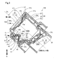
図2は実施形態にかかる燃料タンクの開閉装置20が組み込まれたフィラーネック100を概略視した斜視図である。図3はフィラーネック100の要部を図2の3-3線に沿って断面視して示す説明図である。図4は燃料タンクの開閉装置20の分解斜視図である。なお、以降の説明において部材の位置関係を述べる場合には、燃料タンクFTに近い側を、適宜、「燃料タンク側」と称し、ノズル挿入口104に近い側を、適宜、「挿入側」と称する。また、図3では、構成部材の明確な図示のため、適宜な内部構成部材については断面端面視して示している。 FIG. 2 is a schematic perspective view of a filler neck 100 incorporating the fuel tank opening/closing device 20 according to the embodiment. FIG. 3 is an explanatory diagram showing a cross-sectional view of the main part of the filler neck 100 along line 3-3 in FIG. FIG. 4 is an exploded perspective view of the fuel tank opening/closing device 20. As shown in FIG. In the following description, when describing the positional relationship of the members, the side closer to the fuel tank FT will be referred to as the "fuel tank side", and the side closer to the nozzle insertion port 104 will be referred to as the "insertion side". called. Moreover, in FIG. 3, appropriate internal structural members are shown in cross-sectional end view for clear illustration of the structural members.

図3と図4に示すように、フィラーネック100は、挿入口開閉機構10と、開閉装置20と、タンク側開閉機構30と、排液機構40とを備える。開閉装置20は、給油ノズルFN(図1参照)が挿入されるノズル挿入口104を有するアウターボディー21と、給油ノズルFNのノズル挿入通路100Nを有するインナーボディー22と、燃料タンク側でタンク側開閉機構30をインナーボディー22に組み付けるアンダーボディー23と、給油ノズルFNから供給された液体燃料を燃料タンクFTへと導く燃料通路100Pを形成する燃料通路形成部25とを備える。なお、各ボディーは、ほぼ円筒状の形状とされている。 As shown in FIGS. 3 and 4 , the filler neck 100 includes an insertion port opening/closing mechanism 10 , an opening/closing device 20 , a tank side opening/closing mechanism 30 , and a drainage mechanism 40 . The opening/closing device 20 includes an outer body 21 having a nozzle insertion opening 104 into which a fuel nozzle FN (see FIG. 1) is inserted, an inner body 22 having a nozzle insertion passage 100N for the fuel nozzle FN, and opening and closing on the fuel tank side. It has an underbody 23 that assembles the mechanism 30 to the inner body 22, and a fuel passage forming portion 25 that forms a fuel passage 100P that guides the liquid fuel supplied from the fuel nozzle FN to the fuel tank FT. Each body has a substantially cylindrical shape.

アウターボディー21は、インナーボディー22が組み込まれるカバー本体であって、インナーボディー22を取り囲む周壁21aに大気開放の第2開口42を有する。この第2開口42は、後述のインナーボディー22が有する第1開口41と対向する。また、アウターボディー21は、周壁21aの天井壁21bに給油ノズルFNのノズル挿入口104を有する。ノズル挿入口104は、略円形の孔形状をなす給油口周壁104sにテーパー状のノズル挿入側周壁104tが連続するように形成されている。なお、アウターボディー21は、PA(ポリアミド)等の耐油性樹脂を用いた樹脂成形品である。 The outer body 21 is a cover main body into which the inner body 22 is assembled, and has a second opening 42 open to the atmosphere in the peripheral wall 21a surrounding the inner body 22 . The second opening 42 faces a first opening 41 of an inner body 22, which will be described later. Further, the outer body 21 has a nozzle insertion port 104 for the fuel nozzle FN in the ceiling wall 21b of the peripheral wall 21a. The nozzle insertion port 104 is formed such that a tapered nozzle insertion side peripheral wall 104t is continuous with an oil filler port peripheral wall 104s having a substantially circular hole shape. The outer body 21 is a resin molded product using an oil-resistant resin such as PA (polyamide).

インナーボディー22は、ノズル挿入通路100Nを取り囲む通路周壁22aに第1開口41を有するハウジングであって、この第1開口41によりノズル挿入通路100Nを大気開放する。図3と図4に示すように、インナーボディー22は、通路周壁22aの一部領域をノズル挿入通路100Nの径方向に沿って外側に突出した突出壁部22bとする。その上で、インナーボディー22は、この突出壁部22bに形成した第1開口41をノズル挿入通路100Nに連続させ、第1開口41の開口底部側の通路周壁22aを傾斜壁部22cとする。インナーボディー22は、通路周壁22aを補強するため、ボディー上下のフランジ間に複数のリブを有する他、下方フランジにアウターボディー21に対する保持力の発揮のための突出片を有する。これら部材は、本発明の要旨と直接関係しないので、その説明は省略する。 The inner body 22 is a housing having a first opening 41 in a passage peripheral wall 22a surrounding the nozzle insertion passage 100N. As shown in FIGS. 3 and 4, the inner body 22 has a protruding wall portion 22b that protrudes outward along the radial direction of the nozzle insertion passage 100N from a partial region of the passage peripheral wall 22a. In addition, the inner body 22 connects the first opening 41 formed in the protruding wall portion 22b to the nozzle insertion passage 100N, and the passage peripheral wall 22a on the opening bottom side of the first opening 41 is an inclined wall portion 22c. The inner body 22 has a plurality of ribs between the upper and lower flanges of the body to reinforce the passage peripheral wall 22a, and has a projecting piece on the lower flange for exhibiting a holding force with respect to the outer body 21. As shown in FIG. Since these members are not directly related to the gist of the present invention, their description is omitted.

傾斜壁部22cは、フィラーネック100が車両に装着済みの装着姿勢、より詳しくは、図3に示すように、鉛直方向に対して所定の傾斜角θ1(30~50°)で傾斜した傾斜姿勢にある時に、第1開口41側がノズル挿入通路100N側より少なくとも鉛直下方側に位置するように傾斜する。傾斜壁部22cの機能については、後述する。インナーボディー22と後述のアンダーボディー23は、PA(ポリアミド)等の耐油性樹脂を用いた樹脂成形品である。なお、傾斜角θ1は、鉛直方向に対するノズル挿入通路100N或いは燃料通路100Pの中心軸OLの傾斜角である。 The slanted wall portion 22c is in a mounting posture in which the filler neck 100 is already mounted on the vehicle, more specifically, as shown in FIG. 2, the side of the first opening 41 is inclined so as to be positioned at least vertically below the side of the nozzle insertion passage 100N. The function of the inclined wall portion 22c will be described later. The inner body 22 and an underbody 23, which will be described later, are resin molded products using an oil-resistant resin such as PA (polyamide). The inclination angle θ1 is the inclination angle of the central axis OL of the nozzle insertion passage 100N or the fuel passage 100P with respect to the vertical direction.

挿入口開閉機構10は、アウターボディー21の天井壁21b側に配設され、ノズル挿入口104を開閉する。つまり、この挿入口開閉機構10は、ノズル挿入口104への給油ノズルFNの挿入に伴って挿入口開放位置に移動してノズル挿入口104を開き、給油ノズルFNが挿入されない状態では、ノズル挿入口104の開口底部をノズル挿入通路100N側から閉じる。 The insertion port opening/closing mechanism 10 is arranged on the ceiling wall 21 b side of the outer body 21 and opens and closes the nozzle insertion port 104 . That is, the insertion port opening/closing mechanism 10 moves to the insertion port open position to open the nozzle insertion port 104 as the fuel nozzle FN is inserted into the nozzle insertion port 104, and when the fuel nozzle FN is not inserted, the nozzle insertion The opening bottom of the port 104 is closed from the nozzle insertion passage 100N side.

挿入口開閉機構10は、ノズル挿入口104の開閉用の挿入口開閉部材11と、インナーボディー22に固定されて挿入口開閉部材11を閉める方向に付勢する挿入側スプリング12と、挿入口開閉部材11を取り囲むようアウターボディー21の天井壁21bに装着される環状体15とを備える。環状体15は、多孔質のスポンジゴムの成形品であり、天井壁21bに加わる衝撃を緩和すると共に、燃料蒸気が大気へ流出することを制限する。挿入口開閉部材11は、アウターボディー21よりも疎水性の高い材料、例えばPPS(ポリフェニレンサルファイド)を用いた成形品であり、中央部がノズル挿入通路100N側に窪んだ円板状に形成されている。この挿入口開閉部材11は、図4に示すように、その上面に陥没凹所11aを備える。この陥没凹所11aは、ノズル挿入通路100Nをノズル挿入口104の周壁において大気に連通する連通口として機能する。 The insertion port opening/closing mechanism 10 includes an insertion port opening/closing member 11 for opening/closing the nozzle insertion port 104, an insertion side spring 12 fixed to the inner body 22 and biasing the insertion port opening/closing member 11 in a closing direction, and an insertion port opening/closing member. and an annular body 15 mounted on the ceiling wall 21 b of the outer body 21 so as to surround the member 11 . The ring-shaped body 15 is a porous sponge rubber molded article, which reduces the impact applied to the ceiling wall 21b and restricts fuel vapor from flowing out to the atmosphere. The insertion port opening/closing member 11 is a molded article using a material having a higher hydrophobicity than the outer body 21, such as PPS (polyphenylene sulfide), and is formed in a disc shape with the central portion recessed toward the nozzle insertion passage 100N side. there is As shown in FIG. 4, the insertion slot opening/closing member 11 has a depression 11a on its upper surface. The depression 11a functions as a communication port that communicates the nozzle insertion passage 100N with the atmosphere in the peripheral wall of the nozzle insertion port 104. As shown in FIG.

挿入側スプリング12は、インナーボディー22に固定端12Lで固定され、固定端12Lと反対側の自由端で挿入口開閉部材11に固定されている。挿入側スプリング12は、固定端12Lを中心に所定の角度の範囲で回動し、挿入口開閉部材11を燃料通路100Pが閉まる方向に付勢している。よって、挿入口開閉部材11は、非給油時において、ノズル挿入口104における給油口周壁104sの開口下端側端面に押し付けられて、ノズル挿入口104を閉鎖する。なお、挿入口開閉機構10を、給油ノズルFNの挿入に伴いノズル挿入口104が挿入口正面視で左右、或いは上下に開閉する一対のフラップ弁タイプとしてもよい。 The insertion-side spring 12 is fixed to the inner body 22 at a fixed end 12L, and is fixed to the insertion port opening/closing member 11 at a free end opposite to the fixed end 12L. The insertion-side spring 12 rotates within a predetermined angle range about the fixed end 12L, and urges the insertion port opening/closing member 11 in the direction in which the fuel passage 100P is closed. Therefore, the insertion port opening/closing member 11 is pressed against the opening lower end side end face of the filler port peripheral wall 104s in the nozzle insertion port 104 to close the nozzle insertion port 104 when fuel is not being supplied. The insertion port opening/closing mechanism 10 may be of a pair of flap valve type in which the nozzle insertion port 104 opens and closes horizontally or vertically when the fuel nozzle FN is inserted.

上記した挿入口開閉機構10の挿入口開閉部材11との関係において、アウターボディー21は、給油口周壁104sの下端側端面を、挿入口開閉部材11の着座端面とする。そして、このアウターボディー21は、給油口周壁104sの下端側端面に、図4に示すように、連通口21cを有する。この連通口21cは、給油口周壁104sの下端側端面を切り欠いて形成されている。そして、連通口21cは、既述した挿入口開閉機構10の挿入口開閉部材11がノズル挿入口104を閉じている状況において、挿入口開閉部材11の陥没凹所11aと重なり、陥没凹所11aと共に、ノズル挿入通路100Nをノズル挿入口104の周壁において大気に連通する。なお、陥没凹所11aと連通口21cは、いずれか一方が形成されればよい他、両者が異なる位置に形成されて個別にノズル挿入通路100Nをノズル挿入口104の周壁において大気に連通するようにしてもよい。 In relation to the insertion opening/closing member 11 of the insertion opening/closing mechanism 10 described above, the outer body 21 uses the lower end surface of the filler opening peripheral wall 104s as the seating end surface of the insertion opening/closing member 11 . 4, the outer body 21 has a communication port 21c on the lower end face of the peripheral wall 104s of the filler port. The communication port 21c is formed by notching the lower end face of the peripheral wall 104s of the filler port. The communication port 21c overlaps with the depression 11a of the insertion port opening/closing member 11 when the insertion port opening/closing member 11 of the insertion port opening/closing mechanism 10 is closing the nozzle insertion port 104, and the communication port 21c overlaps the depression 11a. At the same time, the nozzle insertion passage 100N communicates with the atmosphere at the peripheral wall of the nozzle insertion port 104 . Either one of the depression 11a and the communication port 21c may be formed, or both may be formed at different positions so that the nozzle insertion passage 100N is individually communicated with the atmosphere at the peripheral wall of the nozzle insertion port 104. can be

燃料通路形成部25は、アウターボディー21の下端側に組み付けられ、燃料通路100Pを、後述のタンク側開閉機構30を介在させて、インナーボディー22のノズル挿入通路100Nに連続させる。 The fuel passage forming portion 25 is assembled to the lower end side of the outer body 21, and connects the fuel passage 100P to the nozzle insertion passage 100N of the inner body 22 through the tank side opening/closing mechanism 30, which will be described later.

タンク側開閉機構30は、図3に示すように、燃料通路形成部25が形成した燃料通路100Pとノズル挿入通路100Nとが連続した部位に配設され、ノズル挿入通路100Nを燃料タンク側で開閉する。このタンク側開閉機構30の組み付け対象部材はアンダーボディー23であり、アンダーボディー23は、シール部材を介してアウターボディー21とインナーボディー22に対して液密・気密に装着されている。そして、タンク側開閉機構30は、燃料通路形成部25を介してアンダーボディー23に組み付けられ、ノズル挿入通路100Nを開閉するタンク側開閉部材31と、燃料通路形成部25に固定されてタンク側開閉部材31を閉める方向に付勢するタンク側スプリング32と、を備える。タンク側開閉部材31は、燃料タンク側から挿入側への液体燃料の漏洩を防止するフラップ弁である。タンク側スプリング32は、燃料通路形成部25に固定端32Lで固定され、固定端32Lと反対側の自由端でタンク側開閉部材31に固定されている。タンク側スプリング32は、固定端32Lを中心に所定の角度の範囲で回動し、タンク側開閉部材31をノズル挿入通路100Nが閉まる方向に付勢している。タンク側スプリング32は、フィラーネック100が図3に示す傾斜姿勢で車両に装着済みの際、タンク側開閉機構30が閉まっている状態で、固定端32Lが自由端よりも重力方向の上側になるように配置されている。タンク側開閉機構30は、タンク側開閉部材31に調圧機構を備えており、燃料タンクFT内の燃料蒸気圧(タンク内圧)を調圧している。つまり、タンク内圧が規定圧力よりも正圧となったり負圧となる内圧異常時において、タンク側開閉機構30は、タンク内エアーのノズル挿入通路100N側への放出やノズル挿入通路100Nからタンク内への大気導入により、タンク内圧を調整する。 As shown in FIG. 3, the tank side opening/closing mechanism 30 is disposed at a portion where the fuel passage 100P formed by the fuel passage forming portion 25 and the nozzle insertion passage 100N are continuous, and opens and closes the nozzle insertion passage 100N on the fuel tank side. do. A member to be assembled with the tank side opening/closing mechanism 30 is the underbody 23, and the underbody 23 is liquid-tightly and airtightly attached to the outer body 21 and the inner body 22 via sealing members. The tank side opening/closing mechanism 30 is assembled to the underbody 23 via the fuel passage forming portion 25, and includes a tank side opening/closing member 31 that opens and closes the nozzle insertion passage 100N, and a tank side opening/closing member 31 that is fixed to the fuel passage forming portion 25 to open and close the tank side. and a tank-side spring 32 that biases the member 31 in the closing direction. The tank side opening/closing member 31 is a flap valve that prevents liquid fuel from leaking from the fuel tank side to the insertion side. The tank side spring 32 is fixed to the fuel passage forming portion 25 at a fixed end 32L, and is fixed to the tank side opening/closing member 31 at a free end opposite to the fixed end 32L. The tank-side spring 32 rotates within a predetermined angle range around the fixed end 32L, and biases the tank-side opening/closing member 31 in the direction in which the nozzle insertion passage 100N is closed. The fixed end 32L of the tank side spring 32 is positioned above the free end in the direction of gravity when the tank side opening/closing mechanism 30 is closed when the filler neck 100 is installed in the vehicle in the inclined posture shown in FIG. are arranged as The tank-side opening/closing mechanism 30 has a pressure regulating mechanism in the tank-side opening/closing member 31, and regulates the fuel vapor pressure (tank internal pressure) in the fuel tank FT. In other words, when the internal pressure of the tank becomes more positive or negative than the specified pressure, the tank side opening/closing mechanism 30 releases the air in the tank to the side of the nozzle insertion passage 100N or releases the air from the nozzle insertion passage 100N into the tank. The internal pressure of the tank is adjusted by introducing atmospheric air into the tank.

排液機構40は、アウターボディー21とインナーボディー22との間に位置するよう、インナーボディー22に装着されて、インナーボディー22の第1開口41と連続する。この排液機構40は、図4に示すように、インナーボディー22側から、矩形の環状シール体45と、排液口形成部材46と、排液弁47と、保持部材48とを備える。環状シール体45は、耐油性ゴムの成形品であり、インナーボディー22の第1開口41に装着された排液口形成部材46の押圧力を受けて、第1開口41をその開口領域に亘って液密にシールする。 The drainage mechanism 40 is attached to the inner body 22 so as to be positioned between the outer body 21 and the inner body 22 and communicates with the first opening 41 of the inner body 22 . As shown in FIG. 4, the drainage mechanism 40 includes, from the inner body 22 side, a rectangular annular seal member 45, a drainage port forming member 46, a drainage valve 47, and a holding member 48. As shown in FIG. The annular seal member 45 is a molded product made of oil-resistant rubber, and receives the pressing force of a drainage port forming member 46 attached to the first opening 41 of the inner body 22 to extend the first opening 41 over its opening area. liquid-tight seal.

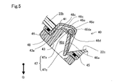
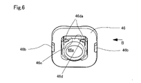
図5は図3における排液機構40の周辺領域を拡大断面視して示す説明図である。図6は排液機構40を構成する排液口形成部材46を図3における矢印A方向から見て示す説明図である。図7は排液口形成部材46を図6における矢印B方向から見て示す説明図である。図8は排液機構40を構成する保持部材48により保持される排液弁47を図3における矢印A方向からの正面図とその右側面図で示す説明図である。図3と図4に示すように、排液口形成部材46は、第1開口41に装着される。こうして装着された排液口形成部材46は、第1開口41側からノズル挿入通路100Nの中心軸OL側に突出して第1開口41側で窪んだ凹所壁46cに排液口46aを有する。この凹所壁46cは、第1開口41側から窪んで囲まれた凹所の領域を、アウターボディー21の第2開口42に連続した排液通路48dとする。また、排液口形成部材46は、図3の断面図および図5の拡大断面図に示すように、排液口46aをテーパー状の台座部46dの取り囲み、後述の排液弁47における弁本体47cを排液口46aの開口上端面で受け止める。図3と図5の断面図に示すように、排液通路48dには、後述の保持部材48の構成部材も位置し、凹所壁46cには、後述の排液弁47が保持される。よって、排液通路48dと凹所壁46cについては、保持部材48や排液弁47の構成と合わせて、後述する。 FIG. 5 is an explanatory view showing an enlarged cross-sectional view of the peripheral area of the drainage mechanism 40 in FIG. FIG. 6 is an explanatory diagram showing the drainage port forming member 46 that constitutes the drainage mechanism 40 as viewed from the direction of arrow A in FIG. FIG. 7 is an explanatory diagram showing the drainage port forming member 46 as viewed from the direction of arrow B in FIG. 8A and 8B are explanatory diagrams showing a front view and a right side view of the drain valve 47 held by the holding member 48 constituting the drain mechanism 40 as seen from the direction of arrow A in FIG. As shown in FIGS. 3 and 4, the drainage port forming member 46 is attached to the first opening 41 . The drain port forming member 46 mounted in this manner protrudes from the first opening 41 side toward the central axis OL side of the nozzle insertion passage 100N and has a drain port 46a in a concave wall 46c recessed on the first opening 41 side. The recess wall 46 c defines a recess area recessed and surrounded from the first opening 41 side as a drainage passage 48 d continuous to the second opening 42 of the outer body 21 . As shown in the cross-sectional view of FIG. 3 and the enlarged cross-sectional view of FIG. 47c is received by the upper end surface of the opening of the drain port 46a. As shown in the cross-sectional views of FIGS. 3 and 5, constituent members of a holding member 48, which will be described later, are also located in the drain passage 48d, and a drain valve 47, which will be described later, is held on the recess wall 46c. Therefore, the drainage passage 48d and the recess wall 46c will be described later together with the configuration of the holding member 48 and the drainage valve 47. FIG.

図3における矢印A方向は、排液口46aの開口面に直交する開口軸線の方向と一致している。よって、図6では、排液口46aの正面視図が示されていることになる。この図6に示すように、排液口46aは、正面視において楕円形の開口である。 The direction of arrow A in FIG. 3 coincides with the direction of the opening axis perpendicular to the opening surface of the drainage port 46a. Therefore, FIG. 6 shows a front view of the drainage port 46a. As shown in FIG. 6, the drain port 46a is an elliptical opening when viewed from the front.

楕円開口の排液口46aを開閉する排液弁47は、図8に示すように、回動軸47aと弁本体47cを有する。弁本体47cは、正面視において楕円形状であり、回動軸47aに平行な長辺の長さが回動軸47aに垂直な短辺の長さよりも長い。本実施形態の排液弁47は、回動軸47aに平行な長辺の長さが回動軸47aに垂直な短辺の長さに対して1.1~1.5倍の寸法に形成された弁本体47cを有する。そして、排液弁47の弁本体47cで閉鎖される排液口46aも、弁本体47cの楕円形状に対応した楕円開口である。排液口46aは、インナーボディー22における傾斜壁部22cの第1開口41側の一端に位置し、傾斜壁部22cと連続している。このため、ノズル挿入通路100Nに入り込んだ液体は、ノズル挿入通路100Nから傾斜壁部22cに導かれて第1開口41に向けて流れ、この排液口46aに自ずから到達する。また、排液口形成部材46は、保持部材48側に凸部46bを有する。この凸部46bについては、後述の保持部材48の構成と関連付けて説明する。 As shown in FIG. 8, the drain valve 47 for opening and closing the oval drain port 46a has a pivot shaft 47a and a valve body 47c. The valve body 47c has an elliptical shape when viewed from the front, and the length of the long side parallel to the rotation shaft 47a is longer than the length of the short side perpendicular to the rotation shaft 47a. The drain valve 47 of this embodiment is formed so that the length of the long side parallel to the rotation shaft 47a is 1.1 to 1.5 times the length of the short side perpendicular to the rotation shaft 47a. and a valve body 47c. The drain port 46a closed by the valve body 47c of the drain valve 47 is also an elliptical opening corresponding to the elliptical shape of the valve body 47c. The drain port 46a is located at one end of the inclined wall portion 22c of the inner body 22 on the side of the first opening 41, and is continuous with the inclined wall portion 22c. Therefore, the liquid that has entered the nozzle insertion passage 100N is guided by the inclined wall portion 22c from the nozzle insertion passage 100N, flows toward the first opening 41, and naturally reaches the drainage port 46a. Further, the liquid drain port forming member 46 has a convex portion 46b on the holding member 48 side. The convex portion 46b will be described in association with the configuration of the holding member 48, which will be described later.

図9は排液機構40を構成する保持部材48を図4における矢印C方向から見て示す説明図である。図10は開閉装置20の要部部品の組み付けの状態を図4における矢印D方向から見て示す説明図である。保持部材48は、枠体の中央域に第3開口43を備え、図4および図10に示すように、第3開口43の上端に、凸部43aを有する。第3開口43は、排液通路48dを経て外部に排出する液体の通過面積を確保するため、開口上端を図10における上方側に延ばして形成されている。そして、第3開口43は、後述の保持片48cを第3開口43側から支えるため、開口上端側が正面視左右方向に狭くされ、狭くされた部位に開口肩部48fを形成する。第3開口43の上端から突出した凸部43aは、その両側の開口肩部48fより、図10における下方、即ち弁本体47cの弁本体上面に向かって突出している。そして、凸部43aは、排液口46aを閉鎖した排液弁47の弁本体47cと向き合う。また、凸部43aは、排液口46aを開放するよう弁本体47cが回動すると、弁本体47cの弁本体上面の一部、詳しくは弁本体47cのほぼ中央上面に当接して弁本体47cの回動を規制する。つまり、凸部43aは、本発明における開弁規制部として機能する。凸部43aは、図5において断面視して示されており、保持部材48前面側の第3開口43から開口奥側に筋状に延びるよう形成されている。保持部材48の開口奥側から前面側の第3開口43に向かう方向は、排液方向であることから、凸部43aは、排液通路48dにおける排液方向に沿って延びることになる。 FIG. 9 is an explanatory diagram showing the holding member 48 that constitutes the drainage mechanism 40 as viewed from the direction of arrow C in FIG. FIG. 10 is an explanatory view showing the assembled state of the main parts of the opening/closing device 20 as seen from the direction of arrow D in FIG. The holding member 48 has a third opening 43 in the central region of the frame, and has a protrusion 43a at the upper end of the third opening 43 as shown in FIGS. The third opening 43 is formed such that the upper end of the opening extends upward in FIG. 10 in order to secure a passage area for the liquid discharged to the outside through the drain passage 48d. Since the third opening 43 supports a later-described holding piece 48c from the third opening 43 side, the upper end of the opening is narrowed in the left-right direction in front view, and an opening shoulder 48f is formed in the narrowed portion. The protrusion 43a protruding from the upper end of the third opening 43 protrudes from the opening shoulders 48f on both sides downward in FIG. 10, that is, toward the upper surface of the valve body 47c. The convex portion 43a faces the valve body 47c of the drain valve 47 that closes the drain port 46a. Further, when the valve body 47c rotates so as to open the drain port 46a, the protrusion 43a abuts on a part of the upper surface of the valve body 47c, more specifically, on the upper surface of the valve body 47c at substantially the center of the valve body 47c. to regulate the rotation of That is, the convex portion 43a functions as a valve opening restricting portion in the present invention. The convex portion 43a is shown in cross section in FIG. 5, and is formed to extend like a stripe from the third opening 43 on the front side of the holding member 48 to the back side of the opening. Since the direction from the inner side of the opening of the holding member 48 toward the third opening 43 on the front side is the liquid drainage direction, the protrusion 43a extends along the liquid drainage direction in the liquid drainage passage 48d.

この他、保持部材48は、第3開口43の枠体から2本の係合腕48aを排液口形成部材46に向けて突出して備える。係合腕48aは、向かい合う間隔が広がるよう可撓性を備え、係合腕基部から先端側まで、一対の長形の係合孔48bを有する。この係合腕48aは、インナーボディー22が第1開口41の周囲、具体的には第1開口41を取り囲む突出壁部22bに有する凸状の係合突起22dを係合孔48bに入り込ませることで、この係合突起22dに係合する。つまり、保持部材48は、インナーボディー22が係合部として有する係合突起22dに係合腕48aを係合させるので、この係合腕48aを、被係合部として機能させる。保持部材48は、インナーボディー22の第1開口41に既述したように装着済みの排液口形成部材46を、この装着状態が保持されるように、インナーボディー22に装着される。具体的には、保持部材48は、係合腕48aの係合孔48bにインナーボディー22の係合突起22dが係合するよう、インナーボディー22に装着され、排液口形成部材46が第1開口41に装着された状態を保持する。本実施形態では、係合孔48bは、係合腕48aの基部を切り欠くよう形成されている。よって、保持部材48がインナーボディー22に装着された状態において、保持部材48の基部側で、係合孔48bに既述した排液口形成部材46の凸部46bが係合する。 In addition, the holding member 48 has two engaging arms 48 a protruding from the frame of the third opening 43 toward the drainage port forming member 46 . The engaging arms 48a are flexible so as to widen the distance between them, and have a pair of elongated engaging holes 48b extending from the base of the engaging arms to the distal end. The engaging arm 48a is formed by inserting the convex engaging projection 22d of the protruding wall portion 22b surrounding the first opening 41 of the inner body 22, specifically the first opening 41, into the engaging hole 48b. , and engages with this engaging projection 22d. In other words, the holding member 48 engages the engaging arm 48a with the engaging protrusion 22d of the inner body 22 as an engaging portion, so that the engaging arm 48a functions as the engaged portion. The holding member 48 is attached to the inner body 22 so that the drainage port forming member 46 already attached to the first opening 41 of the inner body 22 as described above is retained in this attached state. Specifically, the holding member 48 is attached to the inner body 22 so that the engaging protrusions 22d of the inner body 22 engage with the engaging holes 48b of the engaging arms 48a, and the liquid drain port forming member 46 is positioned at the first position. The state of being attached to the opening 41 is maintained. In this embodiment, the engagement hole 48b is formed by cutting the base of the engagement arm 48a. Therefore, when the holding member 48 is attached to the inner body 22 , the projection 46 b of the liquid discharge port forming member 46 is engaged with the engaging hole 48 b on the base side of the holding member 48 .

保持部材48は、図9に示すように、排液口形成部材46側に一対の保持片48cを有する。この保持片48cは、排液口形成部材46の排液口46aを開閉する排液弁47を排液口形成部材46の凹所壁46cに対して保持するための部材である。つまり、保持片48cは、排液口形成部材46が既述したようにインナーボディー22に装着された状態において、回動軸47aの軸表面に向き合って湾曲した湾曲面部位48eで、回動軸47aを保持する。回動軸47aは、弁本体47c側が円柱形状であり、その反対側、即ち中心軸OL側に円柱を切り欠いた平坦部47bを有する。保持片48cは、排液弁47における回動軸47aを、平坦部47bと逆側の円柱形状部側で湾曲面部位48eにより受け止める。湾曲面部位48eは、その曲率が回動軸47aの円柱形状部の曲率より小さくなるように形成されている。排液弁47の回動軸47aは、その円柱形状部側で湾曲面部位48eの曲面に沿って摺動可能に保持された上で、弁本体47cの回動の基点となる。つまり、弁本体47cは、回動軸47aを基点に回動自在であり、この弁本体47cの回動の過程において、回動軸47aは、円柱形状部側で湾曲面部位48eの曲面に沿って摺動し得る。なお、保持片48cによる回動軸47aの保持は、弁本体47cより回動軸47aがノズル挿入通路100Nの中心軸OL側に位置するようになされる。 The holding member 48 has a pair of holding pieces 48c on the side of the liquid drain port forming member 46, as shown in FIG. The holding piece 48 c is a member for holding the drain valve 47 for opening and closing the drain port 46 a of the drain port forming member 46 against the recess wall 46 c of the drain port forming member 46 . In other words, the holding piece 48c, in the state where the drain port forming member 46 is attached to the inner body 22 as described above, has a curved surface portion 48e curved facing the axial surface of the rotating shaft 47a. Hold 47a. The rotary shaft 47a has a columnar shape on the side of the valve body 47c, and has a flat portion 47b formed by notching the column on the opposite side, that is, the side of the central axis OL. The holding piece 48c receives the rotating shaft 47a of the drain valve 47 by the curved surface portion 48e on the cylindrical portion side opposite to the flat portion 47b. The curved surface portion 48e is formed so that its curvature is smaller than the curvature of the cylindrical portion of the rotating shaft 47a. The rotation shaft 47a of the drain valve 47 is held slidably along the curved surface of the curved surface portion 48e on the side of the cylindrical portion, and serves as a base point for rotation of the valve body 47c. In other words, the valve main body 47c is rotatable about the pivot shaft 47a. In the process of pivoting the valve main body 47c, the pivot shaft 47a moves along the curved surface of the curved surface portion 48e on the cylindrical portion side. can slide. The rotating shaft 47a is held by the holding piece 48c so that the rotating shaft 47a is located closer to the central axis OL of the nozzle insertion passage 100N than the valve main body 47c.

排液口形成部材46における凹所壁46cに組み込まれて一対の保持片48cにより保持された排液弁47は、自重により排液口46aを弁本体47cで閉鎖する。この閉鎖状態において、排液弁47の弁本体47cは、図5に示すように、テーパー状の台座部46dにおける排液口46aの開口上端面に接触している。また、排液口形成部材46の凹所壁46cは、図5および図6に示すように、排液口46aの閉鎖状態において凹所壁46cの内周壁46eが排液弁47の回動軸47aと接触しないように、凹み形成されている。この他、図5および図6に示すように、排液口形成部材46は、台座部46dのテーパー状斜面に溝部46daを有する。この溝部46daは、図6のように正面視した排液口46aの両端に陥没して形成されている。既述したように保持片48cで保持された排液弁47との関連で説明すると、溝部46daは、排液弁47の回動軸47aの軸方向両端の側で台座部46dのテーパー状斜面に陥没して形成されており、凹所壁46cの内周壁46eに対する回動軸47aの非接触領域を拡大する。この非接触領域の拡大により、弁本体47cは、回動軸47aを基点として支障なく回動する。より詳しく説明すると、回動軸47aが既述したように円柱形状部側で一対の保持片48cにおけるそれぞれの湾曲面部位48eの曲面に沿って摺動する場合、回動軸47aの一方端側と他方端側とでは、摺動の状況が相違することが有り得る。こうなると、回動軸47aは、軸方向の一方端が他方端より台座部46dのテーパー状斜面に近くなって、傾斜する。こうして回動軸47aが傾斜しても、台座部46dのテーパー状斜面に近くなった回動軸端部は、溝部46daにより、凹所壁46cの内周壁46eに接触しない。よって、弁本体47cは、既述したように、回動軸47aを基点として支障なく回動する。 The drain valve 47, which is incorporated in the recess wall 46c of the drain port forming member 46 and held by a pair of holding pieces 48c, closes the drain port 46a with the valve body 47c by its own weight. In this closed state, the valve body 47c of the drain valve 47 is in contact with the opening upper end surface of the drain port 46a in the tapered base portion 46d, as shown in FIG. As shown in FIGS. 5 and 6, the recess wall 46c of the drain port forming member 46 is arranged so that the inner peripheral wall 46e of the recess wall 46c acts as the rotation shaft of the drain valve 47 when the drain port 46a is closed. It is recessed so as not to come into contact with 47a. In addition, as shown in FIGS. 5 and 6, the drainage port forming member 46 has a groove portion 46da on the tapered slope of the base portion 46d. As shown in FIG. 6, the grooves 46da are recessed at both ends of the drainage port 46a viewed from the front. In relation to the drain valve 47 held by the holding piece 48c as described above, the groove portion 46da is formed on both axial ends of the rotary shaft 47a of the drain valve 47 on the tapered slope of the pedestal portion 46d. to expand the non-contact area of the rotating shaft 47a with respect to the inner peripheral wall 46e of the recess wall 46c. Due to this expansion of the non-contact area, the valve body 47c rotates about the rotation shaft 47a without hindrance. More specifically, when the rotating shaft 47a slides along the curved surfaces of the curved surface portions 48e of the pair of holding pieces 48c on the side of the cylindrical portion as described above, one end side of the rotating shaft 47a and the other end may have different sliding conditions. As a result, one axial end of the rotary shaft 47a becomes closer to the tapered slope of the base portion 46d than the other axial end, and is inclined. Even if the rotary shaft 47a is inclined in this manner, the end of the rotary shaft near the tapered slope of the pedestal portion 46d does not come into contact with the inner peripheral wall 46e of the recess wall 46c due to the groove portion 46da. Therefore, as described above, the valve body 47c rotates around the rotation shaft 47a without hindrance.

その一方、既述したようにノズル挿入通路100Nから傾斜壁部22cを経て第1開口41まで液体が流れると、この流体に弁本体47cが押されて回動軸47aを基点に回動することで、排液口46aを開放する。流体に押されて排液口46aを開放した排液弁47は、保持部材48の第3開口43における凸部43aに弁本体47cが近づくよう回動する。つまり、排液弁47の弁本体47cは、凸部43aとの接触箇所が回動端となるように回動し、凸部43aは排液弁47のストッパとして機能して弁本体47cの回動を規制する。 On the other hand, when the liquid flows from the nozzle insertion passage 100N through the inclined wall portion 22c to the first opening 41 as described above, the valve main body 47c is pushed by this fluid to rotate about the rotation shaft 47a. Then, the drain port 46a is opened. The drain valve 47, which is pushed by the fluid to open the drain port 46a, rotates so that the valve body 47c approaches the protrusion 43a in the third opening 43 of the holding member 48. As shown in FIG. In other words, the valve main body 47c of the drain valve 47 rotates so that the point of contact with the convex portion 43a becomes the rotation end, and the convex portion 43a functions as a stopper of the drain valve 47 to rotate the valve main body 47c. regulate movement.

また、保持部材48は、排液口形成部材46を保持するよう既述したようにインナーボディー22に装着された状態において、図3に示すように、第3開口43をアウターボディー21の第2開口42に連続させる。その上で、保持部材48は、第3開口43と排液口形成部材46における排液口46aとの間における凹所壁46cの既述した凹所領域を、排液口46aから流れ出る液体の第2開口42までの排液通路48dとする。これに加え、保持部材48は、この保持部材48が既述したようにインナーボディー22に装着される過程において、排液口形成部材46の凸部46bを係合孔48bに係合腕48aの先端側から入り込ませる。インナーボディー22への保持部材48の装着が進むにつれて、凸部46bは、係合孔48bに入り込んだまま係合孔48bの基部側に達する。これにより、この凸部46bは、保持部材48がインナーボディー22に係合する際の保持部材48の姿勢を決める位置決め部として機能する。また、保持部材48は、凸部46bと係合突起22dを係合孔48bにおける異なる位置で係合孔48bに係合させる。このため、凸部46bと係合突起22dの係合相手を一つにすることができ、保持部材48の形状を簡素化できる。 3, the holding member 48 is attached to the inner body 22 so as to hold the drain port forming member 46, as shown in FIG. It is made continuous with the opening 42 . In addition, the holding member 48 allows the liquid flowing out of the liquid drain port 46a to pass through the recessed region of the recess wall 46c between the third opening 43 and the liquid drain port 46a of the liquid drain port forming member 46. A drainage passage 48 d extends to the second opening 42 . In addition to this, the holding member 48 is attached to the inner body 22 as described above. Enter from the tip side. As the attachment of the holding member 48 to the inner body 22 progresses, the projection 46b reaches the base side of the engagement hole 48b while remaining in the engagement hole 48b. As a result, the convex portion 46b functions as a positioning portion that determines the posture of the holding member 48 when the holding member 48 is engaged with the inner body 22. As shown in FIG. Further, the holding member 48 engages the projection 46b and the engaging protrusion 22d with the engaging hole 48b at different positions in the engaging hole 48b. Therefore, the projection 46b and the engagement projection 22d can be engaged with one other, and the shape of the holding member 48 can be simplified.

図10に示すように、排液口形成部材46と保持部材48は、排液口46a(図4参照)を排液弁47で閉鎖した状態で、インナーボディー22に既述したように組み付け装着される。そして、インナーボディー22は、排液口形成部材46と保持部材48とが排液弁47を保持していわゆる仮組み付けされた状態で、挿入口開閉機構10および環状体15と共に、アウターボディー21に組み込まれる。詳しくは、図9に示す保持部材48の第3開口43がアウターボディー21の第2開口42に重なるように、インナーボディー22がアウターボディー21に組み込まれる。つまり、排液口形成部材46と保持部材48の仮組み付けができればよいことから、これら部材には厳格な強度設計等が不要となり、製品設計を簡素化することができる。 As shown in FIG. 10, the liquid drain port forming member 46 and the holding member 48 are assembled to the inner body 22 as described above, with the liquid drain port 46a (see FIG. 4) closed by the liquid drain valve 47. be done. The inner body 22 is attached to the outer body 21 together with the insertion port opening/closing mechanism 10 and the annular body 15 in a so-called temporary assembled state in which the drain port forming member 46 and the holding member 48 hold the drain valve 47. incorporated. Specifically, the inner body 22 is incorporated into the outer body 21 so that the third opening 43 of the holding member 48 shown in FIG. 9 overlaps the second opening 42 of the outer body 21 . In other words, since it is only necessary to temporarily assemble the liquid drain port forming member 46 and the holding member 48, these members do not require strict strength design, etc., and product design can be simplified.

以上説明した本実施形態の開閉装置20を有するフィラーネック100では、インナーボディー22が形成するノズル挿入通路100Nから第1開口41に向けて流体が流れると、この液体は、アウターボディー21とインナーボディー22との間に組み込まれた排液機構40の排液口46aに到達する。この場合、本実施形態の開閉装置20を有するフィラーネック100は、図3に示すように、車両に装着済みの装着姿勢において、鉛直方向に対して所定の傾斜角θ1(30~50°)で傾斜した傾斜姿勢であり、傾斜壁部22cを第1開口41側がノズル挿入通路100N側より鉛直下方側となるよう傾斜させる。よって、開閉装置20は、陥没凹所11aおよび連通口21cからノズル挿入通路100Nに入り込んだ雨水等の液体を、既述したように傾斜した傾斜壁部22cにより第1開口41に向けて液体自体の自重を利用して流し出し、排液口46aに到達させる。本実施形態の開閉装置20を有するフィラーネック100は、第1開口41側が鉛直下方側となるように傾斜させた傾斜壁部22cの水平方向に対する傾斜角θ2を、図3に示すように、水平方向から下方側に向けて2~5°とした。これにより、ノズル挿入通路100Nから傾斜壁部22cを経た第1開口41への液体の流れ込みを確保できる。よって、ノズル挿入通路100Nに入り込んだ液体の排液の効率が高まる。また、傾斜壁部22cは、仮にその傾斜角θ2が0°であっても、車両振動等により液体をノズル挿入通路100Nから第1開口41に流して排液するので、傾斜壁部22cの傾斜角θ2は、水平方向から下方側に向けて2~5°が好ましい。 In the filler neck 100 having the opening/closing device 20 of this embodiment described above, when the fluid flows from the nozzle insertion passage 100N formed by the inner body 22 toward the first opening 41, the fluid flows through the outer body 21 and the inner body. 22 and reaches the drainage port 46a of the drainage mechanism 40 incorporated between. In this case, the filler neck 100 having the opening/closing device 20 of the present embodiment, as shown in FIG. This is an inclined posture, and the inclined wall portion 22c is inclined so that the first opening 41 side is vertically lower than the nozzle insertion passage 100N side. Therefore, the opening/closing device 20 directs the liquid such as rainwater entering the nozzle insertion passage 100N from the depression 11a and the communication port 21c toward the first opening 41 by the inclined wall portion 22c as described above. It is allowed to flow out using its own weight and reach the drainage port 46a. In the filler neck 100 having the opening/closing device 20 of the present embodiment, the inclination angle θ2 with respect to the horizontal direction of the inclined wall portion 22c which is inclined so that the first opening 41 side is vertically downward, as shown in FIG. It was 2 to 5 degrees downward from the direction. This ensures that the liquid flows from the nozzle insertion passage 100N to the first opening 41 through the inclined wall portion 22c. Therefore, the efficiency of draining the liquid that has entered the nozzle insertion passage 100N is enhanced. Further, even if the inclination angle θ2 of the inclined wall portion 22c is 0°, the vehicle vibration or the like causes the liquid to flow from the nozzle insertion passage 100N to the first opening 41 and drain. The angle θ2 is preferably 2 to 5° downward from the horizontal direction.

本実施形態の開閉装置20を有するフィラーネック100は、排液口46aまで到達した液体に排液弁47が押されると、この排液弁47により排液口46aを開放する。そうすると、排液弁47を押し開いた液体は、凹所壁46cにおける凹所領域の排液通路48dを通過して、保持部材48の第3開口43に至った上で、この第3開口43に連続するアウターボディー21の第2開口42に流れる。第2開口42は、インナーボディー22を取り囲む周壁21aに形成されて大気開放されていることから、第2開口42まで流れた液体は、この第2開口42から開閉装置20の外部に排液される。 The filler neck 100 having the opening/closing device 20 of the present embodiment opens the drain port 46a by the drain valve 47 when the drain valve 47 is pushed by the liquid reaching the drain port 46a. Then, the liquid that pushes the drain valve 47 open passes through the drain passage 48d in the recessed region of the recessed wall 46c, reaches the third opening 43 of the holding member 48, and then reaches the third opening 43. flows into the second opening 42 of the outer body 21 that continues to the . The second opening 42 is formed in the peripheral wall 21a surrounding the inner body 22 and is open to the atmosphere. be.

インナーボディー22の第1開口41からアウターボディー21の第2開口42までの液体排液に関与する排液機構40は、アウターボディー21とこれに組み込まれるインナーボディー22との間、即ちインナーボディー22の組込領域に配設されるに過ぎない。よって、開閉装置20のアウターボディー21では、周壁21aに大気開放の第2開口42が形成されていれば良く、液体排液のための排液通路の形成部位を装置外部に突出させて設ける必要がない。これに加え、本実施形態の開閉装置20では、排液弁47は、回動軸47aを基点とした弁本体47cの回動により排液口46aを開閉する。そして、この回動軸47aをノズル挿入通路100Nの中心軸OL側に位置させて保持することで、排液弁47が保持される。こうして保持された排液弁47は、液体が排液口46aに達していない状態において、排液口46aを閉鎖し、液体が排液口46aに到達すると、その液体に押されて排液口46aを開放する。この排液口46aの開放の際、弁本体47cは、回動軸47aを基点として回動する。弁本体上面の一部に凸部43aが当接して弁本体47cの回動が規制されると、弁本体47cは、回動停止状態となる。この回動停止状態において、弁本体上面の一部に凸部43aが当接していることから、排液弁47を取り囲む周辺部材の間隙、具体的には、図10に示す凸部43a両側の開口肩部48fの間隙に排液弁47の弁本体47cが入り込まない。この結果、本実施形態の開閉装置20によれば、ノズル挿入通路100Nに入り込んだ液体を確実に排液できるようにした上で、排液口46aを開放する排液弁47の可動性を確保できる。 A drainage mechanism 40 involved in draining liquid from the first opening 41 of the inner body 22 to the second opening 42 of the outer body 21 is provided between the outer body 21 and the inner body 22 incorporated therein, that is, the inner body 22 . It is simply arranged in the integration area of . Therefore, in the outer body 21 of the opening/closing device 20, it is sufficient that the peripheral wall 21a is formed with the second opening 42 that is open to the atmosphere, and it is necessary to provide a portion forming a drainage passage for liquid drainage so as to protrude outside the device. There is no In addition to this, in the opening/closing device 20 of the present embodiment, the drain valve 47 opens and closes the drain port 46a by rotating the valve body 47c about the rotating shaft 47a. The drain valve 47 is held by positioning and holding the rotating shaft 47a on the central axis OL side of the nozzle insertion passage 100N. The drain valve 47 held in this way closes the drain port 46a when the liquid has not reached the drain port 46a, and when the liquid reaches the drain port 46a, the liquid pushes the drain valve 47 to close the drain port 46a. Open 46a. When the drain port 46a is opened, the valve body 47c rotates around the rotation shaft 47a. When the convex portion 43a abuts against a portion of the upper surface of the valve body and the rotation of the valve body 47c is restricted, the valve body 47c stops rotating. In this rotation stop state, since the convex portion 43a is in contact with a part of the upper surface of the valve body, the gap between the peripheral members surrounding the drain valve 47, specifically, the two sides of the convex portion 43a shown in FIG. The valve body 47c of the drain valve 47 does not enter the clearance of the opening shoulder 48f. As a result, according to the opening/closing device 20 of the present embodiment, the liquid that has entered the nozzle insertion passage 100N can be reliably drained, and the mobility of the drain valve 47 that opens the drain port 46a is ensured. can.

本実施形態の開閉装置20を有するフィラーネック100は、回動軸47aを基点とした弁本体47cの回動が起きるように、保持部材48により排液弁47の回動軸47aを保持した上で、この保持部材48に弁本体47cの弁本体上面側に向けて突出した凸部43aを有する。よって、本実施形態の開閉装置20を有するフィラーネック100によれば、排液弁47の保持と凸部43aによる回動規制とを、保持部材48により達成できるので部材の成形性や組み付け性が高まると共に、凸部43aにより確実な弁本体上面の一部への当接を図ることができる。 In the filler neck 100 having the opening/closing device 20 of the present embodiment, the rotating shaft 47a of the drain valve 47 is held by the holding member 48 so that the valve body 47c rotates about the rotating shaft 47a. The holding member 48 has a convex portion 43a projecting toward the upper surface of the valve body 47c. Therefore, according to the filler neck 100 having the opening/closing device 20 of the present embodiment, the holding member 48 can hold the drain valve 47 and restrict the rotation by the convex portion 43a. As the pressure increases, it is possible to achieve reliable contact with a portion of the upper surface of the valve body by the convex portion 43a.

本実施形態の開閉装置20を有するフィラーネック100は、凸部43aを、排液通路48dにおける液体の排液方向に沿って延びる形状に形成している。よって、本実施形態の開閉装置20を有するフィラーネック100によれば、多量の液体が排液通路48dに一度に流れ込んでも、排液方向に沿って延びる凸部43aの傾斜面で液体を案内しつつ、凸部43aと開口肩部48fとの間において液体を第2開口42に導くことができ、排液性を確保できる。 In the filler neck 100 having the opening/closing device 20 of the present embodiment, the convex portion 43a is formed in a shape extending along the liquid drain direction in the liquid drain passage 48d. Therefore, according to the filler neck 100 having the opening/closing device 20 of the present embodiment, even if a large amount of liquid flows into the drainage passage 48d at once, the liquid is guided by the inclined surface of the projection 43a extending along the drainage direction. At the same time, the liquid can be guided to the second opening 42 between the convex portion 43a and the opening shoulder portion 48f, and the liquid drainage can be ensured.

本実施形態の開閉装置20を有するフィラーネック100は、排液口46aを開閉する排液弁47を、第1開口41側からノズル挿入通路100Nの中心軸OL側に突出して窪んだ凹所壁46cの凹所領域の排液通路48dに保持片48cにより保持する。排液弁47の保持領域が第1開口41側からアウターボディー21側に広がるほど、排液機構40の組込領域はアウターボディー21側に広がる。本実施形態の開閉装置20では、排液弁47をノズル挿入通路100Nの中心軸OL側に突出して窪んだ凹所壁46cの凹所領域の排液通路48dに保持しているので、排液機構40の組込領域の広がりを抑制できる。この結果、本実施形態の開閉装置20を有するフィラーネック100によれば、ノズル挿入通路100Nに入り込んだ液体を確実に排液できるようにした上で、開閉装置20のアウターボディー21が装置外部に突出しないようにできる、或いは、突出の程度をより確実に抑制できる。 The filler neck 100 having the opening/closing device 20 of the present embodiment has a recess wall in which a drain valve 47 for opening and closing the drain port 46a protrudes from the first opening 41 side toward the central axis OL side of the nozzle insertion passage 100N. It is held by a holding piece 48c in the drainage passage 48d in the recessed area of 46c. As the holding area of the drain valve 47 expands from the first opening 41 side toward the outer body 21 side, the mounting area of the drain mechanism 40 expands toward the outer body 21 side. In the opening/closing device 20 of the present embodiment, the drain valve 47 is held in the drain passage 48d in the recess area of the recess wall 46c that protrudes toward the central axis OL of the nozzle insertion passage 100N. It is possible to suppress the expansion of the integration area of the mechanism 40 . As a result, according to the filler neck 100 having the opening/closing device 20 of the present embodiment, the liquid that has entered the nozzle insertion passage 100N can be reliably drained, and the outer body 21 of the opening/closing device 20 is outside the device. Protrusion can be prevented, or the degree of protrusion can be suppressed more reliably.

本実施形態の開閉装置20を有するフィラーネック100は、排液弁47の回動軸47aを、この回動軸47aの軸表面に向き合うよう湾曲した一対の保持片48cの湾曲面部位48eで保持する。よって、本実施形態の開閉装置20を有するフィラーネック100によれば、排液弁47を回動軸47aを基点に円滑に回動させることができる。しかも、回動軸47aが一対の保持片48cにおけるそれぞれの湾曲面部位48eの曲面に沿って摺動して傾斜したとしても、溝部46daにより、回動軸47aを排液口形成部材46における凹所壁46cの内周壁46eに接触させない。つまり、回動軸47aが摺動により傾斜しても、弁本体47cは、回動軸47aを基点に支障なく円滑に回動する。これらの結果、ノズル挿入通路100Nに入り込んだ液体の排液性がより高まる。 The filler neck 100 having the opening/closing device 20 of the present embodiment holds the rotating shaft 47a of the drain valve 47 at the curved surface portions 48e of the pair of holding pieces 48c curved to face the shaft surface of the rotating shaft 47a. do. Therefore, according to the filler neck 100 having the opening/closing device 20 of the present embodiment, the drain valve 47 can be smoothly rotated about the rotation shaft 47a. Moreover, even if the rotating shaft 47a slides along the curved surfaces of the curved surface portions 48e of the pair of holding pieces 48c and tilts, the groove portion 46da allows the rotating shaft 47a to be positioned in the concave portion of the drain port forming member 46. It is not brought into contact with the inner peripheral wall 46e of the wall 46c. In other words, even if the rotating shaft 47a slides and tilts, the valve body 47c smoothly rotates about the rotating shaft 47a as a base point. As a result, the drainability of the liquid that has entered the nozzle insertion passage 100N is further enhanced.

本実施形態の開閉装置20を有するフィラーネック100は、排液口形成部材46の凹所壁46cにおける排液通路48dにおいて、排液弁47の弁本体47cを、台座部46dが形成した排液口46aの開口上端面で受け止める。その上で、フィラーネック100は、排液弁47を、その回動軸47aが凹所壁46cの内壁面に接触しないように、保持する。よって、本実施形態の開閉装置20を有するフィラーネック100によれば、弁本体47cを回動軸47aを基点により一層と円滑に回動させることができるので、排液性をより高めることができる。 The filler neck 100 having the opening/closing device 20 of the present embodiment has a drainage passage 48d in the recess wall 46c of the drainage port forming member 46. It is received by the upper end surface of the opening of the mouth 46a. In addition, the filler neck 100 holds the drain valve 47 so that its pivot shaft 47a does not come into contact with the inner wall surface of the recess wall 46c. Therefore, according to the filler neck 100 having the opening/closing device 20 of the present embodiment, the valve body 47c can be more smoothly rotated about the rotation shaft 47a, so that the drainage property can be further improved. .

本実施形態の開閉装置20では、ノズル挿入通路100Nの中心軸OL側に位置する回動軸47aを基点として排液口46aの開閉のために回動する弁本体47cを、正面視において、回動軸47aに垂直な辺が短辺となる楕円形状とした。回動軸47aに垂直な方向の弁本体長さは、ノズル挿入通路100Nの中心軸OLからの排液機構40の組込領域の広がりを規定する。本実施形態の開閉装置20では、回動軸47aに垂直な方向の弁本体長さを回動軸47aに平行な方向の弁本体長さに比べて短くすることで、排液機構40の組込領域の広がりを抑制できる。また、排液口46aを弁本体47cに対応した楕円開口とすることで、ノズル挿入通路100Nに入り込んだ液体を確実に排液可能な開口面積を確保できる。これらの結果、本実施形態の開閉装置20を有するフィラーネック100によれば、ノズル挿入通路100Nに入り込んだ液体を確実に排液できるようにした上で、開閉装置20のアウターボディー21が装置外部に突出しないようにできる、或いは、突出の程度をより確実に抑制できる。これに加え、本実施形態の開閉装置20を有するフィラーネック100によれば、排液機構40への外部からの接触を回避、若しくは抑制できる。 In the opening/closing device 20 of the present embodiment, the valve body 47c, which rotates to open and close the drain port 46a about the rotation shaft 47a located on the central axis OL side of the nozzle insertion passage 100N, is rotated in a front view. An elliptical shape having a short side perpendicular to the driving shaft 47a is used. The length of the valve body in the direction perpendicular to the rotating shaft 47a defines the extension of the area where the drainage mechanism 40 is incorporated from the central axis OL of the nozzle insertion passage 100N. In the opening/closing device 20 of the present embodiment, the length of the valve body in the direction perpendicular to the rotating shaft 47a is shorter than the length of the valve body in the direction parallel to the rotating shaft 47a. It is possible to suppress the spread of the embedded region. Further, by making the drain port 46a an elliptical opening corresponding to the valve main body 47c, it is possible to ensure an opening area capable of reliably draining the liquid that has entered the nozzle insertion passage 100N. As a result, according to the filler neck 100 having the opening/closing device 20 of the present embodiment, the liquid that has entered the nozzle insertion passage 100N can be reliably drained, and the outer body 21 of the opening/closing device 20 can be removed from the outside of the apparatus. It is possible to prevent the protrusion from projecting too far, or to suppress the degree of protrusion more reliably. In addition to this, according to the filler neck 100 having the opening/closing device 20 of the present embodiment, it is possible to avoid or suppress external contact with the drainage mechanism 40 .

本実施形態の開閉装置20を有するフィラーネック100は、排液弁47の回動軸47aを、回動軸47aの中心に対して中心軸OL側に平坦部47bを有する回動軸としたので、平坦部47bとするために回動軸47aが切り欠かれた分だけ、ノズル挿入通路100Nの中心軸OLからの排液機構40の組込領域の広がりをより抑制できる。よって、本実施形態の開閉装置20を有するフィラーネック100によれば、開閉装置20のアウターボディー21の装置外部への突出をより一層、抑制できると共に、排液機構40への外部からの接触をより確実に回避、若しくは抑制できる。 In the filler neck 100 having the opening/closing device 20 of the present embodiment, the rotating shaft 47a of the drain valve 47 is a rotating shaft having a flat portion 47b on the central axis OL side with respect to the center of the rotating shaft 47a. , the expansion of the built-in area of the drainage mechanism 40 from the central axis OL of the nozzle insertion passage 100N can be further suppressed by the amount of the cutout of the rotation shaft 47a to form the flat portion 47b. Therefore, according to the filler neck 100 having the opening/closing device 20 of the present embodiment, it is possible to further suppress the protrusion of the outer body 21 of the opening/closing device 20 to the outside of the device, and to prevent contact with the drainage mechanism 40 from the outside. It can be avoided or suppressed more reliably.

本実施形態の開閉装置20を有するフィラーネック100は、排液弁47の弁本体47cを、回動軸47aに平行な長辺の長さが回動軸47aに垂直な短辺の長さよりも1.1~1.5倍の楕円形状とした。その上で、インナーボディー22に第1開口41に向けて液体を導く傾斜壁部22cを、既述したように、フィラーネック100が傾斜して車両に装着された状態において、第1開口41側が鉛直下方側となるように、水平方向に対して所定の傾斜角θ2(2~5°)で傾斜させた。よって、本実施形態の開閉装置20を有するフィラーネック100によれば、排液機構40の組込領域の広がりをより確実に抑制できると共に、ノズル挿入通路100Nに入り込んだ液体を傾斜した傾斜壁部22cを経て確実に排液できる。 The filler neck 100 having the opening/closing device 20 of the present embodiment has the valve main body 47c of the drain valve 47 so that the length of the long side parallel to the rotation shaft 47a is longer than the length of the short side perpendicular to the rotation shaft 47a. An elliptical shape with a size of 1.1 to 1.5 times was used. Then, the inclined wall portion 22c that guides the liquid toward the first opening 41 is formed in the inner body 22 so that the first opening 41 side faces the first opening 41 side when the filler neck 100 is inclined and attached to the vehicle as described above. It was tilted at a predetermined tilt angle θ2 (2 to 5°) with respect to the horizontal direction so as to be vertically downward. Therefore, according to the filler neck 100 having the opening/closing device 20 of the present embodiment, it is possible to more reliably suppress the expansion of the built-in region of the liquid drainage mechanism 40, and the inclined wall portion which injects the liquid entering the nozzle insertion passage 100N. 22c can be reliably drained.

本実施形態の開閉装置20を有するフィラーネック100は、インナーボディー22の組み付け対象であるアウターボディー21により、排液機構40を外側からインナーボディー22に対して保持する。よって、本実施形態の開閉装置20を有するフィラーネック100によれば、排液機構40を装置外部の側から確実に保持できると共に、排液機構40に外力が直に及ばないようにすることができる。 In the filler neck 100 having the opening/closing device 20 of the present embodiment, the outer body 21 to which the inner body 22 is attached holds the drainage mechanism 40 from the outside to the inner body 22 . Therefore, according to the filler neck 100 having the opening/closing device 20 of the present embodiment, the drainage mechanism 40 can be reliably held from the outside of the device, and the external force can be prevented from being directly applied to the drainage mechanism 40. can.

本実施形態の開閉装置20を有するフィラーネック100は、排液口形成部材46に、保持部材48の係合腕48aがインナーボディー22の係合突起22dに係合する際の保持部材48の姿勢を決める凸部46bを有する。よって、本実施形態の開閉装置20を有するフィラーネック100によれば、排液口形成部材46や保持部材48で構成される排液機構40をインナーボディー22の第1開口41に容易に組み付けることができる。 The filler neck 100 having the opening/closing device 20 of the present embodiment is configured such that the holding member 48 is positioned in the drainage port forming member 46 when the engaging arm 48 a of the holding member 48 engages the engaging projection 22 d of the inner body 22 . has a convex portion 46b that determines the Therefore, according to the filler neck 100 having the opening/closing device 20 of the present embodiment, the drainage mechanism 40 composed of the drainage port forming member 46 and the holding member 48 can be easily assembled to the first opening 41 of the inner body 22. can be done.

本実施形態の開閉装置20を有するフィラーネック100は、インナーボディー22に係合突起22dを備え、排液口形成部材46に係合突起22dが係合孔48bに入り込んで係合する係合腕48aを備える。よって、本実施形態の開閉装置20を有するフィラーネック100によれば、排液口形成部材46や保持部材48で構成される排液機構40を、アウターボディー21へのインナーボディー22の装着前の状態において、インナーボディー22の第1開口41により容易に組み付けることができる。 The filler neck 100 having the opening/closing device 20 of the present embodiment has an engaging projection 22d on the inner body 22, and an engaging arm with which the engaging projection 22d enters the engaging hole 48b to engage with the drain port forming member 46. 48a. Therefore, according to the filler neck 100 having the opening/closing device 20 of the present embodiment, the drainage mechanism 40 composed of the drainage port forming member 46 and the holding member 48 is arranged before the inner body 22 is attached to the outer body 21 . In this state, the first opening 41 of the inner body 22 facilitates assembly.

本実施形態の開閉装置20を有するフィラーネック100は、給油ノズルFNから供給された液体燃料を燃料タンクFTへと導く燃料通路100Pを燃料通路形成部25で形成し、この燃料通路形成部25を、燃料通路100Pがインナーボディー22のノズル挿入通路100Nに連続するようにして、アンダーボディー23を介してインナーボディー22に備える。これに加え、本実施形態の開閉装置20は、燃料通路100Pとノズル挿入通路100Nとが連続した部位に、ノズル挿入通路100Nを開閉するタンク側開閉機構30を有し、アウターボディー21と挿入口開閉機構10に、ノズル挿入通路100Nをノズル挿入口104の周壁において大気に連通する連通口21cや陥没凹所11aを有する。よって、本実施形態の開閉装置20によれば、給油ノズルFNから供給される燃料を燃料タンクFTに導くフィラーネック100を開閉装置20を備えた状態で提供できるほか、燃料タンクFTの内圧異常時においては、タンク側開閉機構30が閉弁状態を解放し、タンク内エアーをノズル挿入口104の周壁の連通口21cや挿入口開閉部材11の陥没凹所11aから大気に放出できる。 In the filler neck 100 having the opening/closing device 20 of this embodiment, the fuel passage forming portion 25 forms the fuel passage 100P for guiding the liquid fuel supplied from the fuel nozzle FN to the fuel tank FT. , the fuel passage 100P is provided in the inner body 22 through the underbody 23 so that the fuel passage 100P is continuous with the nozzle insertion passage 100N of the inner body 22. - 特許庁In addition to this, the opening/closing device 20 of the present embodiment has a tank side opening/closing mechanism 30 for opening and closing the nozzle insertion passage 100N at a portion where the fuel passage 100P and the nozzle insertion passage 100N are continuous. The open/close mechanism 10 has a communication port 21c and a depression 11a that communicate the nozzle insertion passage 100N with the atmosphere in the peripheral wall of the nozzle insertion port 104. As shown in FIG. Therefore, according to the opening/closing device 20 of the present embodiment, the filler neck 100 that guides the fuel supplied from the fuel nozzle FN to the fuel tank FT can be provided in a state in which the opening/closing device 20 is provided. , the tank side opening/closing mechanism 30 is released from the closed state, and the air in the tank can be released to the atmosphere through the communication port 21c in the peripheral wall of the nozzle insertion port 104 and the recessed recess 11a of the insertion port opening/closing member 11 .

なお、本発明は、種々の態様で実現することが可能である。例えば、燃料タンクの開閉装置を有する燃料タンクの形態や、燃料タンクの開閉装置を有するフィラーネックの形態の他、燃料タンクの開閉装置の製造方法等の形態で実現することができる。 It should be noted that the present invention can be implemented in various modes. For example, it can be implemented in the form of a fuel tank having a fuel tank opening/closing device, a filler neck having a fuel tank opening/closing device, or a method of manufacturing a fuel tank opening/closing device.

他の実施形態:
上記の実施形態では、排液弁47を、回動軸47aの軸表面に向き合う保持片48cの湾曲面部位48eで保持したが、湾曲面部位48eに代えて、V字状に窪んだ凹壁面部位で回動軸47aを保持するようにしてもよい。
Other embodiments:
In the above embodiment, the drain valve 47 is held by the curved surface portion 48e of the holding piece 48c facing the shaft surface of the rotating shaft 47a. You may make it hold|maintain the rotating shaft 47a in a site|part.

上記の実施形態では、弁本体47cを受け止める台座部46dをテーパー状としたが、回動軸47aが凹所壁46cの内壁面に接触しないのであれば、テーパー状に限らない。例えば、排液口46aの開口部にて環状に隆起した環状凸部を有する台座部46dとしてもよい。 In the above embodiment, the pedestal portion 46d that receives the valve body 47c is tapered. For example, the pedestal portion 46d may have an annular projection that is annularly raised at the opening of the drainage port 46a.

上記の実施形態では、排液弁47の弁本体47cを、回動軸47aに平行な方向を長辺とする楕円形状としたが、回動軸47aに平行な方向の弁本体長さが回動軸47aに垂直な方向の弁本体長さよりも長ければ楕円形状に限らない。例えば、弁本体47cを、回動軸47aに平行な方向の弁本体長さが回動軸47aに垂直な方向の弁本体長さよりも長い長方形状の弁本体としもよい。 In the above-described embodiment, the valve body 47c of the drain valve 47 has an elliptical shape with the long side parallel to the rotation shaft 47a. The shape is not limited to an elliptical shape as long as it is longer than the length of the valve body in the direction perpendicular to the driving shaft 47a. For example, the valve body 47c may be a rectangular valve body in which the length of the valve body in the direction parallel to the pivot shaft 47a is longer than the length of the valve body in the direction perpendicular to the pivot shaft 47a.

上記の実施形態では、排液口46aを、楕円形状の弁本体47cに対応した楕円形状の開口としたが、弁本体47cで開閉可能な形状の開口であれば、楕円形状に限らない。例えば、排液口46aを、長方形状の弁本体47cに対応した長方形状の開口としたり、楕円形状の弁本体47cで開閉可能な長方形状の開口としてもよい。 In the above-described embodiment, the drain port 46a has an elliptical opening corresponding to the elliptical valve main body 47c. For example, the drain port 46a may be a rectangular opening corresponding to the rectangular valve body 47c, or may be a rectangular opening that can be opened and closed by the elliptical valve body 47c.

上記の実施形態では、排液口形成部材46に凸部46bを設け、この凸部46bを、保持部材48をインナーボディー22に装着する際に、係合孔48bに入り込んで保持部材48の姿勢を決めるものとしたが、これに限らない。例えば、保持部材48における係合腕48aの間隔を排液口形成部材46の幅方向の寸法に合わせて規定することで、保持部材48をインナーボディー22に装着する際の姿勢を決めるようにしてもよい。 In the above-described embodiment, the projection 46b is provided on the drain port forming member 46, and when the holding member 48 is attached to the inner body 22, the projection 46b enters the engagement hole 48b to change the posture of the holding member 48. However, it is not limited to this. For example, by defining the interval between the engaging arms 48a of the holding member 48 according to the widthwise dimension of the drain port forming member 46, the posture when the holding member 48 is attached to the inner body 22 is determined. good too.

上記の実施形態では、給油ノズルFNから供給された液体燃料を燃料タンクFTへと導く燃料通路100Pを形成する燃料通路形成部25と、ノズル挿入通路100Nを開閉するタンク側開閉機構30とを有するようにしたが、これに限らない。例えば、タンク側開閉機構30だけを有する開閉装置20とすることもできる。具体的には、開閉装置20に加えてタンク側開閉機構30や燃料通路形成部25を有するフィラーネック100としての形態ではなく、開閉装置20としての形態としてもよい。 The above-described embodiment has the fuel passage forming portion 25 that forms the fuel passage 100P that guides the liquid fuel supplied from the fuel nozzle FN to the fuel tank FT, and the tank side opening/closing mechanism 30 that opens and closes the nozzle insertion passage 100N. However, it is not limited to this. For example, the opening/closing device 20 may have only the tank side opening/closing mechanism 30 . Specifically, the opening/closing device 20 may be used instead of the filler neck 100 having the tank side opening/closing mechanism 30 and the fuel passage forming portion 25 in addition to the opening/closing device 20 .

本発明は、上述の実施形態や実施例、変形例に限られるものではなく、その趣旨を逸脱しない範囲において種々の構成で実現することができる。例えば、発明の概要の欄に記載した各形態中の技術的特徴に対応する実施形態、実施例、変形例中の技術的特徴は、上述の課題の一部または全部を解決するために、あるいは、上述の効果の一部または全部を達成するために、適宜、差し替えや組み合わせを行うことが可能である。また、その技術的特徴が本明細書中に必須なものとして説明されていなければ、適宜、削除することが可能である。 The present invention is not limited to the above-described embodiments, examples, and modifications, and can be implemented in various configurations without departing from the spirit of the present invention. For example, the technical features in the embodiments, examples, and modifications corresponding to the technical features in each form described in the outline of the invention are used to solve some or all of the above problems, or In order to achieve some or all of the above-described effects, it is possible to appropriately replace or combine them. Also, if the technical features are not described as essential in this specification, they can be deleted as appropriate.

10…挿入口開閉機構、11…挿入口開閉部材、11a…陥没凹所、12…挿入側スプリング、12L…固定端、15…環状体、20…開閉装置、21…アウターボディー、21a…周壁、21b…天井壁、21c…連通口、22…インナーボディー、22a…通路周壁、22b…突出壁部、22c…傾斜壁部、22d…係合突起、23…アンダーボディー、25…燃料通路形成部、30…タンク側開閉機構、31…タンク側開閉部材、32…タンク側スプリング、32L…固定端、40…排液機構、41…第1開口、42…第2開口、43…第3開口、43a…凸部、45…環状シール体、46…排液口形成部材、46a…排液口、46b…凸部、46c…凹所壁、46d…台座部、46da…溝部、46e…内周壁、47…排液弁、47a…回動軸、47b…平坦部、47c…弁本体、48…保持部材、48a…係合腕、48b…係合孔、48c…保持片、48d…排液通路、48e…湾曲面部位、48f…開口肩部、100…フィラーネック、100N…ノズル挿入通路、100P…燃料通路、102…燃料蒸気ポート、104…ノズル挿入口、104s…給油口周壁、104t…ノズル挿入側周壁、BV…ガス放出弁、FE…装着部材、FN…給油ノズル、FP…フィラーパイプ、FR…給油室、FS…給油装置、FT…燃料タンク、NT…燃料蒸気チューブ、OL…中心軸、TV…逆止弁 DESCRIPTION OF SYMBOLS 10... Insertion slot opening/closing mechanism, 11... Insertion slot opening/closing member, 11a... Recessed recess, 12... Insertion side spring, 12L... Fixed end, 15... Annular body, 20... Opening/closing device, 21... Outer body, 21a... Peripheral wall, 21b Ceiling wall 21c Communication port 22 Inner body 22a Passage wall 22b Protruding wall 22c Inclined wall 22d Engagement projection 23 Underbody 25 Fuel passage forming portion 30 Tank side opening/closing mechanism 31 Tank side opening/closing member 32 Tank side spring 32L Fixed end 40 Drainage mechanism 41 First opening 42 Second opening 43 Third opening 43a Convex portion 45 Annular seal member 46 Drain port forming member 46 a Drain port 46 b Convex portion 46 c Recess wall 46 d Base portion 46 da Groove portion 46 e Inner peripheral wall 47 Drainage valve 47a Turning shaft 47b Flat portion 47c Valve body 48 Holding member 48a Engagement arm 48b Engagement hole 48c Holding piece 48d Drainage passage 48e Curved surface portion 48f Opening shoulder 100 Filler neck 100N Nozzle insertion passage 100P Fuel passage 102 Fuel vapor port 104 Nozzle insertion opening 104s Filling port peripheral wall 104t Nozzle insertion side Peripheral wall, BV... Gas release valve, FE... Mounting member, FN... Refueling nozzle, FP... Filler pipe, FR... Refueling chamber, FS... Refueling device, FT... Fuel tank, NT... Fuel vapor tube, OL... Center shaft, TV …Check valve

Claims (2)

燃料タンクの開閉装置(20)であって、
給油ノズル(FN)のノズル挿入通路(100N)を取り囲むように形成された通路周壁(22a)と、前記通路周壁(22a)に形成されて前記ノズル挿入通路(100N)を大気開放する第1開口(41)とを有するハウジング(22)と、
前記ハウジング(22)が組み込まれるカバー本体(21)であって、前記ハウジング(22)を取り囲むように形成された周壁(21a)と、前記周壁(21a)に形成されて前記第1開口(41)と対向する大気開放の第2開口(42)とを有し、前記周壁(21a)の天井壁(21b)に前記給油ノズル(FN)のノズル挿入口(104)を有する前記カバー本体(21)と、
前記ノズル挿入口(104)を開閉する挿入口開閉機構(10)と、
前記第1開口(41)と連続するように前記ハウジング(22)に装着されて、前記カバー本体(21)と前記ハウジング(22)との間に位置する排液機構(40)とを有し、
前記排液機構(40)は、
前記第1開口(41)から前記第2開口(42)に至るまでの排液通路(48d)であって、前記ノズル挿入通路(100N)から前記第1開口(41)に向けて流れる液体の排液口(46a)を前記第1開口(41)に連続させて備える前記排液通路(48d)と、
弁本体(47c)と、前記弁本体(47c)よりも前記ノズル挿入通路(100N)の中心軸(OL)側に位置するように保持された回動軸(47a)とを備え、前記回動軸(47a)を基点とした前記弁本体(47c)の回動により前記排液口(46a)を開閉する排液弁(47)と、
前記排液口(46a)を閉鎖した前記排液弁(47)の前記弁本体(47c)と向き合い、前記排液口(46a)を開放するよう前記弁本体(47c)が回動すると、前記弁本体(47c)の弁本体上面の一部に当接して前記弁本体(47c)の回動を規制する開弁規制部(43a)とを備え、
前記排液機構(40)は、
前記回動軸(47a)を基点とした前記弁本体(47c)の回動が起きるように、前記排液弁(47)の前記回動軸(47a)を保持する保持部材(48)を備え、
前記保持部材(48)に、前記開弁規制部(43a)として、前記弁本体(47c)の前記弁本体上面側に突出した凸部(43a)を備える、燃料タンクの開閉装置(20)。
A fuel tank opening and closing device (20),
A passage peripheral wall (22a) formed to surround a nozzle insertion passage (100N) of a fuel nozzle (FN), and a first opening formed in the passage peripheral wall (22a) to open the nozzle insertion passage (100N) to the atmosphere. a housing (22) having (41);
A cover body (21) into which the housing (22) is incorporated, comprising a peripheral wall (21a) formed to surround the housing (22), and the first opening (41) formed in the peripheral wall (21a). ) and a second opening (42) open to the atmosphere facing the cover body (21 )When,
an insertion port opening/closing mechanism (10) for opening and closing the nozzle insertion port (104);
a drainage mechanism (40) mounted on the housing (22) so as to be continuous with the first opening (41) and positioned between the cover body (21) and the housing (22); ,
The drainage mechanism (40)
A drainage passage (48d) from the first opening (41) to the second opening (42), in which the liquid flowing from the nozzle insertion passage (100N) toward the first opening (41) the drainage passage (48d) having a drainage port (46a) connected to the first opening (41);
A valve main body (47c) and a pivot shaft (47a) held so as to be positioned closer to the central axis (OL) of the nozzle insertion passage (100N) than the valve main body (47c), a drainage valve (47) for opening and closing the drainage port (46a) by rotating the valve body (47c) about the shaft (47a);
When the valve body (47c) faces the valve body (47c) of the liquid drain valve (47) that closes the liquid drain port (46a) and rotates to open the liquid drain port (46a), the a valve opening restricting portion (43a) that abuts on a part of the upper surface of the valve body (47c) to restrict rotation of the valve body (47c) ;
The drainage mechanism (40)
A holding member (48) for holding the pivot shaft (47a) of the drain valve (47) so that the valve body (47c) pivots about the pivot shaft (47a) is provided. ,
A fuel tank opening/closing device (20), wherein the holding member (48) is provided with a protrusion (43a) protruding toward the upper surface of the valve body (47c) as the valve opening restricting portion (43a).
請求項1に記載の燃料タンクの開閉装置(20)であって、
前記凸部(43a)は、前記排液通路(48d)における前記液体の排液方向に沿って延びるよう形成されている、燃料タンクの開閉装置(20)。
The fuel tank opening/closing device (20) according to claim 1,
A fuel tank opening/closing device (20), wherein the projection (43a) is formed to extend along a direction in which the liquid is drained in the drain passage (48d).
JP2019022208A 2018-09-28 2019-02-12 fuel tank switchgear Active JP7143561B2 (en)

Priority Applications (3)

Application Number Priority Date Filing Date Title
JP2019022208A JP7143561B2 (en) 2019-02-12 2019-02-12 fuel tank switchgear
US16/567,225 US10843555B2 (en) 2018-09-28 2019-09-11 Opening/closing device of fuel tank
CN201910910898.9A CN110962587B (en) 2018-09-28 2019-09-25 Fuel tank opening and closing device

Applications Claiming Priority (1)

Application Number Priority Date Filing Date Title
JP2019022208A JP7143561B2 (en) 2019-02-12 2019-02-12 fuel tank switchgear

Publications (2)

Publication Number Publication Date
JP2020128182A JP2020128182A (en) 2020-08-27
JP7143561B2 true JP7143561B2 (en) 2022-09-29

Family

ID=72174125

Family Applications (1)

Application Number Title Priority Date Filing Date
JP2019022208A Active JP7143561B2 (en) 2018-09-28 2019-02-12 fuel tank switchgear

Country Status (1)

Country Link
JP (1) JP7143561B2 (en)

Citations (8)

* Cited by examiner, † Cited by third party
Publication number Priority date Publication date Assignee Title
JP2009202836A (en) 2008-02-29 2009-09-10 Toyoda Gosei Co Ltd Check valve
JP2012202485A (en) 2011-03-25 2012-10-22 Asahi Organic Chemicals Industry Co Ltd Wafer type check valve
DE202017100715U1 (en) 2016-02-12 2017-03-27 Gerdes Gmbh Lidless nozzle end for a fuel filler neck and fuel filler neck with a capless closure
JP2017114272A (en) 2015-12-24 2017-06-29 豊田合成株式会社 Fuel tank opening and closing device
US20180079296A1 (en) 2016-09-19 2018-03-22 Honda Motor Co., Ltd. Fuel filler structure of fuel supply pipe
US20180154768A1 (en) 2016-12-01 2018-06-07 GM Global Technology Operations LLC Fuel door arrangement for a motor vehicle
WO2018193883A1 (en) 2017-04-19 2018-10-25 八千代工業株式会社 Fuel fill opening structure
JP6448479B2 (en) 2015-06-22 2019-01-09 ヒロセ電機株式会社 Protective cover, electrical connector with conductive strip and protective cover assembly

Family Cites Families (2)

* Cited by examiner, † Cited by third party
Publication number Priority date Publication date Assignee Title
JPS6327108Y2 (en) * 1981-02-24 1988-07-22
JPS6448479U (en) * 1987-09-18 1989-03-24

Patent Citations (8)

* Cited by examiner, † Cited by third party
Publication number Priority date Publication date Assignee Title
JP2009202836A (en) 2008-02-29 2009-09-10 Toyoda Gosei Co Ltd Check valve
JP2012202485A (en) 2011-03-25 2012-10-22 Asahi Organic Chemicals Industry Co Ltd Wafer type check valve
JP6448479B2 (en) 2015-06-22 2019-01-09 ヒロセ電機株式会社 Protective cover, electrical connector with conductive strip and protective cover assembly
JP2017114272A (en) 2015-12-24 2017-06-29 豊田合成株式会社 Fuel tank opening and closing device
DE202017100715U1 (en) 2016-02-12 2017-03-27 Gerdes Gmbh Lidless nozzle end for a fuel filler neck and fuel filler neck with a capless closure
US20180079296A1 (en) 2016-09-19 2018-03-22 Honda Motor Co., Ltd. Fuel filler structure of fuel supply pipe
US20180154768A1 (en) 2016-12-01 2018-06-07 GM Global Technology Operations LLC Fuel door arrangement for a motor vehicle
WO2018193883A1 (en) 2017-04-19 2018-10-25 八千代工業株式会社 Fuel fill opening structure

Also Published As

Publication number Publication date
JP2020128182A (en) 2020-08-27

Similar Documents

Publication Publication Date Title
JP4123350B2 (en) Backflow prevention valve
JP5319974B2 (en) Filling port closing device
US10442289B2 (en) Opening/closing apparatus for fuel tank
JP6965634B2 (en) Fuel tank switchgear
JP2010522118A (en) Fuel injection pipe head with closure assembly
JP2011500455A (en) Filling nozzle positioning device
US4809865A (en) Fuel tank for use in a vehicle
JP6838270B2 (en) Fuel tank switchgear
JP6626236B2 (en) Filler structure
JP2003276457A (en) Connector for fuel tank
JP6841251B2 (en) Fuel valve
US6675843B2 (en) Non-return valve for fuel tank
JP7143561B2 (en) fuel tank switchgear
JP7155818B2 (en) fuel tank switchgear
CN110962587B (en) Fuel tank opening and closing device
JP7001032B2 (en) Fuel tank switchgear
JPH1178549A (en) Fuel back-flow preventing valve
JP2020050233A (en) Opening/closing device for fuel tank
US7757880B2 (en) Tank cap
US20190275881A1 (en) Fuel supply device
JPH02299930A (en) Flap valve device
US9919596B2 (en) Open-close device for fuel tank
JP6658502B2 (en) Fuel tank switchgear
JPH1128938A (en) Check valve
JP2522681Y2 (en) Liquid seal structure for fuel inlet pipe

Legal Events

Date Code Title Description
A621 Written request for application examination

Free format text: JAPANESE INTERMEDIATE CODE: A621

Effective date: 20210528

A977 Report on retrieval

Free format text: JAPANESE INTERMEDIATE CODE: A971007

Effective date: 20220317

A131 Notification of reasons for refusal

Free format text: JAPANESE INTERMEDIATE CODE: A131

Effective date: 20220329

A521 Request for written amendment filed

Free format text: JAPANESE INTERMEDIATE CODE: A523

Effective date: 20220513

TRDD Decision of grant or rejection written
A01 Written decision to grant a patent or to grant a registration (utility model)

Free format text: JAPANESE INTERMEDIATE CODE: A01

Effective date: 20220809

A61 First payment of annual fees (during grant procedure)

Free format text: JAPANESE INTERMEDIATE CODE: A61

Effective date: 20220822

R151 Written notification of patent or utility model registration

Ref document number: 7143561

Country of ref document: JP

Free format text: JAPANESE INTERMEDIATE CODE: R151