JP7142862B2 - Electrode manufacturing method, electrode and hydrogen manufacturing method - Google Patents
Electrode manufacturing method, electrode and hydrogen manufacturing method Download PDFInfo
- Publication number
- JP7142862B2 JP7142862B2 JP2018136041A JP2018136041A JP7142862B2 JP 7142862 B2 JP7142862 B2 JP 7142862B2 JP 2018136041 A JP2018136041 A JP 2018136041A JP 2018136041 A JP2018136041 A JP 2018136041A JP 7142862 B2 JP7142862 B2 JP 7142862B2
- Authority
- JP
- Japan
- Prior art keywords
- electrode
- metal
- cobalt
- compound
- water
- Prior art date
- Legal status (The legal status is an assumption and is not a legal conclusion. Google has not performed a legal analysis and makes no representation as to the accuracy of the status listed.)
- Active
Links
Images


Classifications
-
- Y—GENERAL TAGGING OF NEW TECHNOLOGICAL DEVELOPMENTS; GENERAL TAGGING OF CROSS-SECTIONAL TECHNOLOGIES SPANNING OVER SEVERAL SECTIONS OF THE IPC; TECHNICAL SUBJECTS COVERED BY FORMER USPC CROSS-REFERENCE ART COLLECTIONS [XRACs] AND DIGESTS
- Y02—TECHNOLOGIES OR APPLICATIONS FOR MITIGATION OR ADAPTATION AGAINST CLIMATE CHANGE
- Y02E—REDUCTION OF GREENHOUSE GAS [GHG] EMISSIONS, RELATED TO ENERGY GENERATION, TRANSMISSION OR DISTRIBUTION
- Y02E60/00—Enabling technologies; Technologies with a potential or indirect contribution to GHG emissions mitigation
- Y02E60/30—Hydrogen technology
- Y02E60/50—Fuel cells
Description
本発明は、電極の製造方法、電極及び水素の製造方法に関する。 TECHNICAL FIELD The present invention relates to a method for manufacturing an electrode, an electrode, and a method for manufacturing hydrogen.
水素は燃焼時にCO2排出がゼロであることから、化石燃料に代わるクリーンなエネルギー源として期待されている。特に、太陽光、風力、水力等の再生可能なエネルギーを電力とする水の電気分解法による水素の製造方法は一切CO2を排出しないことから、クリーンな水素製造方法として大きな期待が寄せられている。 Since hydrogen emits zero CO2 when burned, it is expected to be a clean energy source to replace fossil fuels. In particular, the method of producing hydrogen by water electrolysis, which uses renewable energy such as sunlight, wind power, and water power as power, does not emit any CO2 , so there are great expectations for it as a clean hydrogen production method. there is
一般に、水の電気分解用の電極としては、炭素基材上に白金粒子触媒を固定したものが用いられている。しかしながら、白金は価格が高く、資源量にも限りがあるため、白金の使用量を低減する技術や白金代替触媒及び/又は電極の開発が求められている。 Generally, as an electrode for electrolysis of water, a carbon substrate on which a platinum particle catalyst is fixed is used. However, platinum is expensive and its resources are limited, so there is a demand for the development of techniques for reducing the amount of platinum used and the development of platinum-alternative catalysts and/or electrodes.
白金の使用量を低減する方法としては、例えば、特許文献1において、白金をアノード、炭素基材をカソードとして、希硫酸中で電解処理を行うことにより、希硫酸中に微量溶解した白金イオンを炭素基材上に析出させる技術が開示されている。また、水の電気分解用の白金代替電極としては、例えば、特許文献2において、導電性基材の表面に卑金属酸化物層を形成し、当該卑金属酸化物層上に金、銀等の貴金属を担持させた電極が開示されている。
As a method for reducing the amount of platinum used, for example, in
しかしながら、近年において、水の電気分解等に用いられる電極には、従来の電極よりもさらなる性能の向上が望まれており、また、そのような電極を簡便な方法で製造することが望まれていた。特に、過電圧の上昇が起こりにくく、高い活性を有する電極が強く要望されており、また、そのような電極を簡便な方法で製造できる製造技術の構築が望まれていた。 However, in recent years, electrodes used for electrolysis of water and the like are desired to have further improved performance compared to conventional electrodes, and it is desired to manufacture such electrodes by a simple method. rice field. In particular, there is a strong demand for an electrode that is less prone to an increase in overvoltage and has high activity, and there has also been a demand for construction of a manufacturing technology that can manufacture such an electrode by a simple method.
本発明は、上記に鑑みてなされたものであり、過電圧の上昇が起こりにくく、高い活性を有する電極を簡便な方法で製造できる電極の製造方法及び電極、並びに水素の製造方法を提供することを目的とする。 The present invention has been made in view of the above, and aims to provide a method for producing an electrode, an electrode, and a method for producing hydrogen, which can easily produce an electrode having high activity without causing an increase in overvoltage. aim.
本発明者らは、上記目的を達成すべく鋭意研究を重ねた結果、例えば、水熱合成法とパルス電着法とを組み合わせるなどして、電極材料を特定組成とすることにより上記目的を達成できることを見出し、本発明を完成するに至った。 As a result of intensive research to achieve the above object, the present inventors have achieved the above object by, for example, combining the hydrothermal synthesis method and the pulse electrodeposition method to make the electrode material have a specific composition. I found that it can be done, and came to complete the present invention.
すなわち、本発明は、例えば、以下の項に記載の主題を包含する。
項1
金属M1の化合物(ここで、金属M1はFe、Ni、Cr、Cu、Zn、Mn及びMoからなる群より選ばれる少なくとも1種である)及び第1のコバルト化合物を含む溶液Aに電極基材を浸漬した状態で加熱処理した後、前記電極基材を取り出して焼成する工程1と、
前記工程1で焼成された電極基材を、第2のコバルト化合物及び金属M2の化合物(ここで、金属M2はFe、Ni、Cr、Cu、Zn、Mn及びMoからなる群より選ばれる少なくとも1種である)を含む溶液B中でパルス電着処理を行う工程2と、
を具備する、電極の製造方法。
項2
前記工程2を経て得られる電極は、電極基材上に複合酸化物と層状複水酸化物とが形成されており、
前記複合酸化物は、Co及び前記金属M1を含む酸化物であり、前記層状複水酸化物は、コバルト及び前記金属M2を含有する、項1に記載の製造方法。
項3
電極基材上にCo及び金属M1(ここで、金属M1はFe、Ni、Cr、Cu、Zn、Mn及びMoからなる群より選ばれる少なくとも1種である)を含む複合酸化物と、コバルト及び金属M2(ここで、金属M2はFe、Ni、Cr、Cu、Zn、Mn及びMoからなる群より選ばれる少なくとも1種である)を含有する層状複水酸化物が形成されている、電極。
項4
項1又は2に記載の製造方法で得られた電極又は項3に記載の電極を使用して、水溶液中で電解処理を行う工程を含む、水素の製造方法。
項5
前記電極をアノード及びカソードの少なくとも一方に使用する、項4に記載の製造方法。
That is, the present invention includes, for example, the subject matter described in the following sections.
a compound of metal M1 (here, metal M1 is at least one selected from the group consisting of Fe, Ni, Cr, Cu, Zn, Mn and Mo) and an electrode base material in solution A containing a first cobalt compound; A
The electrode base material fired in the
A method of manufacturing an electrode, comprising:
The electrode obtained through the
Item 3
A composite oxide containing Co and metal M1 (here, metal M1 is at least one selected from the group consisting of Fe, Ni, Cr, Cu, Zn, Mn and Mo) on an electrode substrate, cobalt and An electrode in which a layered double hydroxide containing metal M2 (here, metal M2 is at least one selected from the group consisting of Fe, Ni, Cr, Cu, Zn, Mn and Mo) is formed.
Item 3. A method for producing hydrogen, comprising the step of performing electrolytic treatment in an aqueous solution using the electrode obtained by the production method according to
本発明の電極の製造方法によれば、過電圧の上昇が起こりにくく、高い活性を有する電極を簡便な方法で製造できる。 According to the method for producing an electrode of the present invention, an electrode having a high activity in which overvoltage is unlikely to occur can be produced by a simple method.
本発明の電極は、例えば、水の電気分解において、過電圧の上昇が起こりにくく、高い活性を有するので、水素を効率よく製造することができる。 INDUSTRIAL APPLICABILITY The electrode of the present invention, for example, in the electrolysis of water, does not easily cause an increase in overvoltage and has high activity, so that hydrogen can be efficiently produced.
以下、本発明の実施形態について詳細に説明する。なお、本明細書中において、「含有」及び「含む」なる表現については、「含有」、「含む」、「実質的にからなる」及び「のみからなる」という概念を含む。 BEST MODE FOR CARRYING OUT THE INVENTION Hereinafter, embodiments of the present invention will be described in detail. In this specification, the expressions "contain" and "include" include the concepts of "contain", "include", "substantially consist of" and "consist only of".
1.電極の製造方法及び電極
本発明の電極の製造方法は、少なくとも下記の工程1及び工程2を具備する。
工程1:金属M1の化合物(ここで、金属M1はFe、Ni、Cr、Cu、Zn、Mn及びMoからなる群より選ばれる少なくとも1種である)及び第1のコバルト化合物を含む溶液Aに電極基材を浸漬した状態で加熱処理した後、前記電極基材を取り出して焼成する工程。
工程2:前記工程1で焼成された電極基材を、第2のコバルト化合物及び金属M2の化合物(ここで、金属M2はFe、Ni、Cr、Cu、Zn、Mn及びMoからなる群より選ばれる少なくとも1種である)を含む溶液B中でパルス電着処理を行う工程。
1. Electrode Production Method and Electrode The electrode production method of the present invention comprises at least
Step 1: A solution A containing a compound of metal M1 (here, metal M1 is at least one selected from the group consisting of Fe, Ni, Cr, Cu, Zn, Mn and Mo) and a first cobalt compound After the electrode base material is heat-treated while being immersed, the electrode base material is taken out and baked.
Step 2: The electrode base material fired in
本発明の製造方法は、上記工程1及び工程2を具備することにより、工程が簡便であり、容易に電極を製造することができる。また、得られた電極は、例えば、水の電気分解等に使用した場合に、過電圧の上昇が起こりにくく、高い活性を有することができる。さらに、本発明の製造方法で得られた電極は、例えば、水の電気分解用の電極として使用した場合に、アノード及びカソードのいずれにも適用することができる。
Since the production method of the present invention includes
工程1では、金属M1の化合物及び第1のコバルト化合物を含む溶液Aに電極基材を浸漬した状態で加熱処理をし、次いで、電極基材を取り出して焼成を行う工程である。この工程1は、電極基材上に金属M1とコバルトを含む複合酸化物を形成するための工程である。
In
金属M1はFe、Ni、Cr、Cu、Zn、Mn及びMoからなる群より選ばれる少なくとも1種である。つまり、金属M1は特定種の2価又は3価の遷移金属元素である。金属M1は、コバルトとの複合酸化物を形成しやすく、また、過電圧を抑制しやすい電極を形成しやすい観点から、Fe(鉄)、Ni(ニッケル)であることが好ましく、鉄であることが特に好ましい。 Metal M1 is at least one selected from the group consisting of Fe, Ni, Cr, Cu, Zn, Mn and Mo. That is, the metal M1 is a specific kind of divalent or trivalent transition metal element. The metal M1 is preferably Fe (iron) or Ni (nickel) from the viewpoint of easily forming a composite oxide with cobalt and easily forming an electrode that easily suppresses overvoltage, and is preferably iron. Especially preferred.
工程1で使用する金属M1の化合物の種類は特に限定されない。例えば、金属M1の化合物としては、公知の無機酸塩、公知の有機酸塩、金属M1の水酸化物及び金属M1のハロゲン化物等を広く使用することができる。
The type of compound of metal M1 used in
金属M1の無機酸塩としては、金属M1の硝酸塩、塩酸塩、硫酸塩、炭酸塩、炭酸水素塩、リン酸塩及びリン酸水素塩等からなる郡より選ばれる1種以上を挙げることができる。 Examples of the inorganic acid salt of the metal M1 include one or more selected from the group consisting of nitrates, hydrochlorides, sulfates, carbonates, hydrogen carbonates, phosphates, hydrogen phosphates, etc. of the metal M1. .
金属M1の有機酸塩としては、金属M1の酢酸塩、シュウ酸塩、蟻酸塩、コハク酸塩等からなる郡より選ばれる1種以上を挙げることができる。 Examples of organic acid salts of metal M1 include one or more selected from the group consisting of metal M1 acetates, oxalates, formates, succinates, and the like.
工程1で使用する金属M1の化合物としては、水に溶解して水溶液を形成しやすく、また、複合酸化物が得られやすいという観点から、金属M1の硝酸塩又は塩酸塩であることが好ましい。金属M1の化合物は水和物であってもよい。特に、金属M1の化合物は、後記する第1のコバルト化合物と同じ種類の塩であることが好ましい。例えば、第1のコバルト化合物が硝酸塩である場合は、金属M1の化合物も硝酸塩であることが好ましく、第1のコバルト化合物が塩酸塩である場合は、金属M1の化合物も塩酸塩であることが好ましい。
The compound of the metal M1 used in
工程1で使用する金属M1の化合物は1種単独で使用してもよいし、2種以上を併用することもできる。金属M1の化合物は、公知の製造方法で得ることができ、あるいは、市販の金属M1の化合物を使用することもできる。
The compound of metal M1 used in
工程1で使用する第1のコバルト化合物の種類は特に限定されない。例えば、第1のコバルト化合物としては、コバルトの無機酸塩、公知の有機酸塩、コバルトの水酸化物及びコバルトのハロゲン化物等を広く使用することができる。
The type of the first cobalt compound used in
コバルトの無機酸塩としては、コバルトの硝酸塩、塩酸塩、硫酸塩、炭酸塩、炭酸水素塩、リン酸塩及びリン酸水素塩等からなる郡より選ばれる1種以上を挙げることができる。 Examples of inorganic acid salts of cobalt include one or more selected from the group consisting of cobalt nitrates, hydrochlorides, sulfates, carbonates, hydrogen carbonates, phosphates, hydrogen phosphates, and the like.
コバルトの有機酸塩としては、コバルトの酢酸塩、シュウ酸塩、蟻酸塩、コハク酸塩等からなる郡より選ばれる1種以上を挙げることができる。 Examples of the organic acid salt of cobalt include one or more selected from the group consisting of cobalt acetate, oxalate, formate, succinate, and the like.
工程1で使用する第1のコバルト化合物としては、水に溶解して水溶液を形成しやすく、また、複合酸化物が得られやすいという観点から、コバルトの硝酸塩または塩酸塩であることが好ましい。第1のコバルト化合物は水和物であってもよい。特に、前述のように、金属M1の化合物と第1のコバルト化合物とは、塩の種類が同じであることが好ましい(例えば、硝酸塩どうしの組み合わせ、あるいは、塩酸塩どうしの組み合わせが好ましい)。
The first cobalt compound used in
工程1で使用する第1のコバルト化合物は1種単独で使用してもよいし、2種以上を併用することもできる。第1のコバルト化合物は、公知の製造方法で得ることができ、あるいは、市販の第1のコバルト化合物を使用することもできる。
The first cobalt compound used in
工程1で使用する溶液Aは、金属M1の化合物及び第1のコバルト化合物と、溶媒とを含む。
Solution A used in
溶媒としては、水、あるいは、水と低級アルコール(例えば、メタノール、エタノール等の炭素数1~4のアルコール)との混合物を使用することができ、特に好ましくは、水である。水は、蒸留水、水道水、工業用水、イオン交換水、脱イオン水、純水、電解水などの各種の水を用いることができる。溶媒には、本発明の効果が阻害されない限り、pH調整剤、粘度調整剤、防かび剤等を含有していてもよい。 As the solvent, water or a mixture of water and a lower alcohol (eg, an alcohol having 1 to 4 carbon atoms such as methanol and ethanol) can be used, and water is particularly preferred. Various types of water such as distilled water, tap water, industrial water, ion-exchanged water, deionized water, pure water, and electrolyzed water can be used as the water. The solvent may contain pH adjusters, viscosity adjusters, fungicides and the like as long as the effects of the present invention are not impaired.
溶液Aにおいて、金属M1の化合物及び第1のコバルト化合物の濃度は特に限定されない。例えば、溶液Aにおいて、溶媒100mLあたり、金属M1の化合物が1~100mmol溶解していることが好ましい。この場合、構造が安定な複合酸化物を容易に形成することができる。 In solution A, the concentrations of the compound of metal M1 and the first cobalt compound are not particularly limited. For example, in solution A, 1 to 100 mmol of the compound of metal M1 is preferably dissolved per 100 mL of solvent. In this case, a composite oxide having a stable structure can be easily formed.
また、溶液Aにおいて、溶媒100mLあたり、第1のコバルト化合物が1~100mmol溶解していることが好ましい。この場合、構造が安定な複合酸化物を容易に形成することができる。 Further, in the solution A, 1 to 100 mmol of the first cobalt compound is preferably dissolved per 100 mL of the solvent. In this case, a composite oxide having a stable structure can be easily formed.
溶液Aにおいて、金属M1とコバルト(Co)との元素比は任意の範囲に調整することができる。例えば、溶液Aに含まれる金属M1とコバルト(Co)との元素比M1:Coは、工程1で形成される金属M1とコバルトとの複合酸化物が花びら状等の形状に形成されて電極性能が向上しやすいという観点から、1:10~1:0.1の範囲とすることが好ましい。元素比M1:Coは、1:5~1:2の範囲であることがより好ましく、1:3程度であることが特に好ましい。
In the solution A, the elemental ratio between the metal M1 and cobalt (Co) can be adjusted within an arbitrary range. For example, the element ratio M1:Co between the metal M1 and cobalt (Co) contained in the solution A is such that the composite oxide of the metal M1 and cobalt formed in the
溶液Aは、金属M1の化合物及び第1のコバルト化合物以外に他の添加剤を含むこともできる。他の添加剤としては、例えば、pH調整剤を挙げることができる。pH調整剤としては、尿素(CO(NH2)2)、NH4F、水酸化アンモニウム等を挙げることができる。pH調整剤は1種のみ又は2種以上を組み合わせて使用することができる。 Solution A may also contain other additives besides the compound of metal M1 and the first cobalt compound. Other additives include, for example, pH adjusters. Examples of pH adjusters include urea (CO(NH 2 ) 2 ), NH 4 F, ammonium hydroxide, and the like. A pH adjuster can be used only 1 type or in combination of 2 or more types.
溶液Aにおいて、溶媒100mLあたり、尿素が15~30mmol溶解していることが好ましい。この場合、溶液Aがアルカリ領域のpHを有しやすく、これにより工程1で形成される金属M1とコバルトとの複合酸化物が花びら状等の形状に形成されて電極性能が向上しやすくなる。
In solution A, 15 to 30 mmol of urea are preferably dissolved per 100 mL of solvent. In this case, the solution A tends to have a pH in the alkaline region, whereby the composite oxide of the metal M1 and cobalt formed in
溶液Aにおいて、溶媒100mLあたり、NH4Fが10~20mmol溶解していることが好ましい。この場合、複合酸化物を容易に形成することができる。この場合、溶液Aがアルカリ領域のpHを有しやすく、これにより工程1で形成される金属M1とコバルトとの複合酸化物が花びら状等の形状に形成されて電極性能が向上しやすくなる。
In solution A, 10 to 20 mmol of NH 4 F are preferably dissolved per 100 mL of solvent. In this case, a composite oxide can be easily formed. In this case, the solution A tends to have a pH in the alkaline region, whereby the composite oxide of the metal M1 and cobalt formed in
溶液Aは、金属M1の化合物、第1のニッケル化合物、pH調整剤及び溶媒のみからなるものであってもよい。 Solution A may consist of only the compound of metal M1, the first nickel compound, the pH adjuster and the solvent.
溶液Aに浸漬する電極基材としては、特に限定されず、例えば、公知の導電性の基材を広く採用することができる。電極基材としては、例えば、ニッケル、炭素、ニッケル-リン合金、ニッケル-タングステン合金、ステンレス、チタン、鉄、銅、導電ガラスなどが挙げられる。 The electrode base material to be immersed in the solution A is not particularly limited, and for example, a wide range of known conductive base materials can be employed. Examples of electrode substrates include nickel, carbon, nickel-phosphorus alloys, nickel-tungsten alloys, stainless steel, titanium, iron, copper, and conductive glass.
溶液Aに浸漬する電極基材がニッケル基材又は銅基材等の各種金属基材であることが好ましく、特にニッケル基材であることが好ましい。この場合、所望の電極を製造することが容易となり、また、得られる電極は、水の電気分解等において、過電圧の上昇が起こりにくく、高い活性を有しやすい。より具体的に電極基材としては、ニッケルフォームを例示することができる。 The electrode base material to be immersed in the solution A is preferably a nickel base material, a copper base material or other metal base material, and particularly preferably a nickel base material. In this case, it becomes easy to produce a desired electrode, and the obtained electrode tends to have a high activity in the electrolysis of water, etc., without causing an increase in overvoltage. More specifically, nickel foam can be exemplified as the electrode base material.
電極基材は、公知の方法で得ることができ、あるいは、市販の電極基材を採用することもできる。 The electrode base material can be obtained by a known method, or a commercially available electrode base material can be used.
電極基材の形状は特に制限されず、使用目的や要求される性能により適宜選択することができる。例えば、シート状、板状、棒状、メッシュ状等の電極基材が挙げられる。 The shape of the electrode substrate is not particularly limited, and can be appropriately selected according to the purpose of use and required performance. Examples thereof include sheet-like, plate-like, rod-like, and mesh-like electrode base materials.
電極基材は、溶液Aに浸漬する前にあらかじめ洗浄処理を行うことができる。洗浄処理の方法は特に限定されず、公知の方法を広く採用することができる。例えば、電極基材を塩酸等の酸で洗浄する方法が挙げられる。酸洗浄するにあたっては、超音波処理を組み合わせることもできる。 Before being immersed in the solution A, the electrode substrate can be washed in advance. The method of cleaning treatment is not particularly limited, and a wide range of known methods can be employed. For example, there is a method of washing the electrode base material with an acid such as hydrochloric acid. Ultrasonic treatment can be combined with acid cleaning.
電極基材を溶液Aに浸漬する方法は特に限定されず、通常は、電極基材の全体が溶液Aに浸されるように行うことができる。電極基材の浸漬は、例えば、後記する水熱合成が可能な容器内で行うことができる。このような容器として、耐圧式のオートクレーブを挙げることができる。オートクレーブの内面は、例えば、フッ素樹脂(例えば、テフロン(登録商標)でコーティングされていても良い。 The method of immersing the electrode base material in the solution A is not particularly limited, and usually the whole electrode base material can be immersed in the solution A. The immersion of the electrode base material can be performed, for example, in a vessel capable of hydrothermal synthesis, which will be described later. As such a container, a pressure-resistant autoclave can be mentioned. The inner surface of the autoclave may be coated with, for example, fluororesin (eg, Teflon (registered trademark)).
工程1では、電極基材を溶液Aに浸漬した状態で加熱処理を行う。工程1の加熱処理としては、水熱合成法を挙げることができる。ここでいう水熱合成法は、電極基材を溶液Aに浸漬した状態で容器を密閉し、該容器内を加熱する方法である。この水熱合成により、電極基材上に金属M1とコバルトを含む複合水酸化物が形成され得る。
In
水熱合成における容器内の温度は、金属M1とコバルトを含む複合酸化物が形成される条件である限りは特に制限されず、例えば、110~150℃とすることができる。この温度にて容器を保持する時間も特に限定されず、例えば、8~15時間とすることができる。水熱合成における容器内の圧力も適宜設定することができる。 The temperature inside the vessel in the hydrothermal synthesis is not particularly limited as long as the conditions are such that a composite oxide containing metal M1 and cobalt is formed, and can be, for example, 110 to 150.degree. The time for which the container is held at this temperature is also not particularly limited, and can be, for example, 8 to 15 hours. The pressure inside the vessel in the hydrothermal synthesis can also be set appropriately.
水熱合成において、溶液Aはアルカリ領域であることが好ましく、例えば、pHが7~14であることが好ましく、8~10であることがより好ましく、9程度であることが特に好ましい。この場合、水熱合成において、水酸化物がより形成しやすくなり、また、最終的に工程1で形成される複合酸化物は、花びら状等の形状に形成されて電極性能が向上しやすくなる。
In hydrothermal synthesis, the solution A is preferably in the alkaline region, for example, preferably has a pH of 7 to 14, more preferably 8 to 10, and particularly preferably about 9. In this case, the hydroxide is more easily formed in the hydrothermal synthesis, and the composite oxide finally formed in
工程1において、加熱処理(水熱合成)の後は、容器から電極基材を取り出して焼成を行う。
In
工程1において、焼成の方法は特に限定されず、例えば、公知の焼成方法を広く採用することができる。
In
焼成温度は、例えば、300~400℃とすることができ、340~380℃とすることが好ましい。焼成時間は、焼成温度によって適宜選択すればよく、例えば、1.5~5時間とすることができる。工程1において、焼成を行う際の昇温速度も特に限定されず、所望の酸化物が形成される程度に適宜設定することができる。
The firing temperature can be, for example, 300 to 400.degree. C., preferably 340 to 380.degree. The firing time may be appropriately selected depending on the firing temperature, and may be, for example, 1.5 to 5 hours. In
焼成は、空気中及び不活性ガス雰囲気中のいずれで行ってもよい。好ましくは、空気中で焼成を行うことである。焼成は、例えば、市販の加熱炉等の公知の加熱装置を使用することができる。 Firing may be performed in air or in an inert gas atmosphere. Preferably, the firing is carried out in air. For calcination, for example, a known heating device such as a commercially available heating furnace can be used.
上記焼成によって、電極基材上の水酸化物が酸化物へと変化し、金属M1とコバルトとを含む複合酸化物(CoM1O)で修飾された電極基材を得ることができる。 By the firing, the hydroxide on the electrode substrate changes to an oxide, and an electrode substrate modified with a composite oxide (CoM1O) containing metal M1 and cobalt can be obtained.
工程2は、前記工程1で焼成された電極基材、つまり、複合酸化物で修飾された電極基材を、第2のコバルト化合物及び金属M2の化合物を含む溶液B中でパルス電着処理を行う工程である。この工程2は、コバルト及び金属M2の層状複水酸化物を形成するための工程である。
In
工程2で使用する第2のコバルト化合物の種類は特に限定されない。例えば、第2のコバルト化合物としては、公知の無機酸塩及び公知の有機酸塩、コバルトの水酸化物、コバルトのハロゲン化物等を広く使用することができる。
The type of the second cobalt compound used in
コバルトの無機酸塩としては、コバルトの硝酸塩、塩酸塩、硫酸塩、炭酸塩、炭酸水素塩、リン酸塩及びリン酸水素塩等からなる郡より選ばれる1種以上を挙げることができる。 Examples of inorganic acid salts of cobalt include one or more selected from the group consisting of cobalt nitrates, hydrochlorides, sulfates, carbonates, hydrogen carbonates, phosphates, hydrogen phosphates, and the like.
コバルトの有機酸塩としては、コバルトの酢酸塩、シュウ酸塩、蟻酸塩、コハク酸塩等からなる郡より選ばれる1種以上を挙げることができる。 Examples of the organic acid salt of cobalt include one or more selected from the group consisting of cobalt acetate, oxalate, formate, succinate, and the like.
工程2で使用する第2のコバルト化合物としては、水和物であってもよい。
The second cobalt compound used in
工程2で使用する第2のコバルト化合物は1種単独で使用してもよいし、2種以上を併用することもできる。第2のコバルト化合物は、公知の製造方法で得ることができ、あるいは、市販の第2のコバルト化合物を使用することもできる。
The second cobalt compound used in
本発明の製造方法において、工程1で使用する第1のコバルト化合物と、第2のコバルト化合物とは互いに同一であってもよいし、異なっていてもよい。
In the production method of the present invention, the first cobalt compound and the second cobalt compound used in
金属M2はFe、Ni、Cr、Cu、Zn、Mn及びMoからなる群より選ばれる少なくとも1種である。つまり、金属M2は特定種の2価又は3価の遷移金属元素である。金属M2は、コバルトとの層状複水酸化物を形成しやすく、また、過電圧を抑制しやすい電極を形成しやすい観点から、Ni(ニッケル)、Fe(鉄)であることが好ましく、ニッケルであることが特に好ましい。 Metal M2 is at least one selected from the group consisting of Fe, Ni, Cr, Cu, Zn, Mn and Mo. That is, the metal M2 is a specific kind of divalent or trivalent transition metal element. The metal M2 is preferably Ni (nickel) or Fe (iron) from the viewpoint of easily forming a layered double hydroxide with cobalt and easily forming an electrode that easily suppresses overvoltage, and is nickel. is particularly preferred.
工程2で使用する金属M2の化合物の種類は特に限定されない。例えば、金属M2の化合物としては、公知の無機酸塩、公知の有機酸塩、金属M2の水酸化物、金属M2のハロゲン化物等を広く使用することができる。
The type of compound of metal M2 used in
金属M2の無機酸塩としては、金属M2の硝酸塩、塩酸塩、硫酸塩、炭酸塩、炭酸水素塩、リン酸塩及びリン酸水素塩等からなる郡より選ばれる1種以上を挙げることができる。 Examples of the inorganic acid salt of the metal M2 include one or more selected from the group consisting of nitrates, hydrochlorides, sulfates, carbonates, hydrogencarbonates, phosphates and hydrogenphosphates of the metal M2. .
金属M2の有機酸塩としては、金属M2の酢酸塩、シュウ酸塩、蟻酸塩、コハク酸塩等からなる郡より選ばれる1種以上を挙げることができる。 Examples of organic acid salts of metal M2 include one or more selected from the group consisting of metal M2 acetates, oxalates, formates, succinates, and the like.
金属M2の化合物は、水和物であってもよい。 The compound of metal M2 may be a hydrate.
工程2で使用する金属M2の化合物は1種単独で使用してもよいし、2種以上を併用することもできる。金属M2の化合物は、公知の製造方法で得ることができ、あるいは、市販の金属M2の化合物を使用することもできる。
The compound of metal M2 used in
工程2で使用する溶液Bは、第2のコバルト化合物及び金属M2の化合物と、溶媒とを含む。
Solution B used in
溶媒としては、溶液Aで使用する溶媒と同様の種類を挙げることができ、特に好ましくは、水である。水は、蒸留水、水道水、工業用水、イオン交換水、脱イオン水、純水、電解水などの各種の水を用いることができる。溶媒には、本発明の効果が阻害されない限り、pH調整剤、粘度調整剤、防かび剤等を含有していてもよい。 As the solvent, the same types as those used in solution A can be used, and water is particularly preferred. Various types of water such as distilled water, tap water, industrial water, ion-exchanged water, deionized water, pure water, and electrolyzed water can be used as the water. The solvent may contain pH adjusters, viscosity adjusters, fungicides and the like as long as the effects of the present invention are not impaired.
溶液Bにおいて、第2のコバルト化合物及び金属M2の化合物の濃度は特に限定されない。例えば、溶液Bにおいて、溶媒100mLあたり、第2のコバルト化合物が0.1~100mmol溶解していることが好ましく、3~10mmol溶解していることがより好ましい。この場合、パルス電着により、電析を容易に行える。 In the solution B, the concentrations of the second cobalt compound and the metal M2 compound are not particularly limited. For example, in solution B, the second cobalt compound is preferably dissolved in an amount of 0.1 to 100 mmol, more preferably 3 to 10 mmol, per 100 mL of the solvent. In this case, electrodeposition can be easily performed by pulse electrodeposition.
また、溶液Bにおいて、溶媒100mLあたり、金属M2の化合物が0.1~100mmol溶解していることが好ましく、1~8mmol溶解していることがより好ましい。この場合、パルス電着により、電析を容易に行える。 In the solution B, the compound of metal M2 is preferably dissolved in an amount of 0.1 to 100 mmol, more preferably 1 to 8 mmol per 100 mL of the solvent. In this case, electrodeposition can be easily performed by pulse electrodeposition.
溶液Bにおいて、コバルト(Co)と金属M2の元素比は任意の範囲に調整することができる。例えば、溶液Bにおけるコバルト(Co)と金属M2のとの元素比Co:M2は、電極性能が向上しやすいという観点から、1:10~1:0.1の範囲とすることが好ましく、1:5~1:1.5の範囲であることがより好ましく、3:2程度であることが特に好ましい。 In solution B, the elemental ratio of cobalt (Co) and metal M2 can be adjusted within an arbitrary range. For example, the element ratio Co:M2 between cobalt (Co) and metal M2 in solution B is preferably in the range of 1:10 to 1:0.1 from the viewpoint of easily improving the electrode performance. :5 to 1:1.5 is more preferable, and about 3:2 is particularly preferable.
溶液Bは、第2のコバルト化合物及び金属M2の化合物以外に他の添加剤を含むこともできる。例えば、電着処理を行う際に併用される公知の添加剤が溶液Bに含まれていてもよい。 Solution B may also contain other additives besides the second cobalt compound and the compound of metal M2. For example, the solution B may contain known additives that are used in conjunction with the electrodeposition treatment.
溶液Bは、第2のコバルト化合物、金属M2の化合物、溶媒のみからなるものであってもよい。 Solution B may consist of only the second cobalt compound, the compound of metal M2, and the solvent.
工程2では、工程1によって得られた電極基材を溶液Bに浸漬した状態でパルス電着処理を行う。このパルス電着処理により、電極基材に、層状複水酸化物が形成される。
In
パルス電着処理では、アノードとして工程1によって得られた電極基材を使用する。一方、パルス電着処理を行う際のカソードとしては、例えば、公知の不溶性電極を使用することができる。不溶性電極としては、例えば、炭素、白金族金属、金などを素材とする電極を用いることができる。白金族金属としては、白金(Pt)、パラジウム(Pd)、ルテニウム(Ru)、ロジウム(Rh)、オスミウム(Os)、及びイリジウム(Ir)が挙げられ、中でも白金(Pt)が好ましい。白金族金属は、合金、金属酸化物等の状態で含まれていてもよい。
The pulse electrodeposition process uses the electrode substrate obtained by
カソードの形状は特に制限されず、使用目的や要求される性能により適宜選択することができる。形状としては、例えば、金属線、シート状、板状、棒状、メッシュ状などが挙げられる。具体的には、螺旋状白金線、白金板などを例示することができる。 The shape of the cathode is not particularly limited, and can be appropriately selected depending on the purpose of use and required performance. Examples of shapes include metal wire, sheet, plate, rod, and mesh. Specifically, a spiral platinum wire, a platinum plate, and the like can be exemplified.
パルス電着処理において、溶液BのpHは、コバルト及び金属M2の層状複水酸化物を析出させることができる範囲であれば特に制限されず、例えば6未満、好ましくは0~4程度、より好ましくは0~2程度である。 In the pulse electrodeposition treatment, the pH of the solution B is not particularly limited as long as the layered double hydroxide of cobalt and metal M2 can be deposited, for example less than 6, preferably about 0 to 4, more preferably is about 0 to 2.
パルス電着処理を行う際、アノード、カソード及び溶液B(電解液)の他、参照電極、電解装置、電源、制御ソフトウェア等を使用することができる。これらは、例えば目的に応じて公知のものを使用することができる。例えば、参照電極としては、銀/塩化銀電極(Ag/AgCl電極)、水銀/塩化水銀電極(Hg/HgCl2電極)、標準水素電極などを使用することができる。 In addition to the anode, cathode and solution B (electrolyte), a reference electrode, an electrolytic device, a power supply, control software, etc. can be used when performing the pulse electrodeposition treatment. Known ones can be used as these, for example, depending on the purpose. For example, as a reference electrode, a silver/silver chloride electrode (Ag/AgCl electrode), a mercury/mercury chloride electrode (Hg/ HgCl2 electrode), a standard hydrogen electrode, or the like can be used.
本発明において、パルス電着処理は、金属イオンの電着速度を制御できる電着処理法であり、例えば、高端電圧と低端電圧とを一定周期で印加するパルス電圧法(PPM)、高端電流と低端電流とを一定周期で印加するパルス電流法(PGM)、高端電圧の印加と開回路状態とを一定周期で繰り返し行う単極性パルス電圧法(UPED)などが挙げられる。 In the present invention, the pulse electrodeposition treatment is an electrodeposition treatment method capable of controlling the electrodeposition speed of metal ions. and a low-end current are applied in a constant cycle (PGM), and a unipolar pulse voltage method (UPED) in which a high-end voltage and an open-circuit state are repeatedly applied at a constant cycle.
パルス電着処理法として、単極性パルス電圧法(UPED)を採用する場合、単極性パルス電圧法の条件としては導電性基材上に層状複水酸化物を形成させることができる条件であれば特に制限されず、例えば、電圧:-2~-0.6V、開回路状態、パルス時間:0.5~3秒、パルス印加回数:100~1000回の条件で行うことができる。この場合、層状複水酸化物の析出量、厚み及び密度が適切となって、電極の性能が向上しやすい。 When a unipolar pulsed voltage method (UPED) is employed as the pulse electrodeposition treatment method, the conditions for the unipolar pulsed voltage method are those that allow formation of a layered double hydroxide on the conductive substrate. There are no particular restrictions, and for example, voltage: -2 to -0.6 V, open circuit state, pulse time: 0.5 to 3 seconds, number of pulse applications: 100 to 1000 times. In this case, the deposition amount, thickness and density of the layered double hydroxide are appropriate, and the performance of the electrode is likely to be improved.
パルス電着処理を行う際の溶液Bの温度は特に制限されず、例えば0~50℃程度、好ましくは20~30℃とすることができる。 The temperature of solution B during pulse electrodeposition is not particularly limited, and can be, for example, about 0 to 50.degree. C., preferably 20 to 30.degree.
以上の工程2を経て得られる電極は、電極基材上に複合酸化物と層状複水酸化物とが形成されてなる。複合酸化物は、コバルト(Co)及び金属M1(例えば、Fe)を含む酸化物であり、層状複水酸化物は、コバルト及び金属M2(例えばNi)を含有する。複合酸化物に含まれる金属は、コバルト(Co)及び金属M1のみであってもよいし、その他、例えば、不可避的に含まれる金属を含んでもよい。層状複水酸化物に含まれる金属は、コバルト(Co)及び金属M2のみであってもよいし、その他、例えば、不可避的に含まれる金属を含んでもよい。
The electrode obtained through
複合酸化物は、例えば、電極基材上において、花びら状に形成され、電極基材に対して強い密着力を有している。さらに、工程2で形成される層状複水酸化物は、複合酸化物表面を被覆するように形成されており、電極の電気伝導度および活性点を大きく増加させる作用を有することができる。
The composite oxide is formed, for example, in a petal shape on the electrode substrate and has strong adhesion to the electrode substrate. Furthermore, the layered double hydroxide formed in
本発明の製造方法で得られる電極は、金属M1とコバルトを含む複合酸化物と、コバルト及び金属M2の層状複水酸化物とを有することから、例えば、水の電気分解等に使用した場合に、過電圧の上昇が起こりにくく、高い活性を有することができる。さらに、本発明の製造方法で得られた電極は、例えば、水の電気分解用の電極として使用した場合に、アノード及びカソードのいずれにも適用することができる。従って、本発明の製造方法で得られる電極は、各種の用途に広く適用することができ、特に、水の電気分解用の電極、水素製造用の電極として好適に使用することができる。 Since the electrode obtained by the production method of the present invention has a composite oxide containing metal M1 and cobalt and a layered double hydroxide of cobalt and metal M2, for example, when used for water electrolysis etc. , the overvoltage is less likely to rise and can have high activity. Furthermore, the electrode obtained by the manufacturing method of the present invention can be applied to both an anode and a cathode when used as an electrode for water electrolysis, for example. Therefore, the electrode obtained by the production method of the present invention can be widely applied to various uses, and can be particularly suitably used as an electrode for electrolysis of water and an electrode for hydrogen production.
電極において、コバルト及び金属M1を含む複合酸化物と、コバルト及び金属M2を含有する層状複水酸化物との比率は特に限定されず、任意の比率に調整することができる。 In the electrode, the ratio of the composite oxide containing cobalt and metal M1 and the layered double hydroxide containing cobalt and metal M2 is not particularly limited, and can be adjusted to any ratio.
本発明の製造方法で得られる電極は、例えば、電極基材上に花びら状の粒子が多数積層された構造を有する。粒子の大きさは、例えば、1~20μmである。ここでいう粒子の大きさは、電極の走査型電子顕微鏡による直接観察によって無作為に50個の粒子を選択し、これらの円相当径を計測して算術平均した値をいう。 The electrode obtained by the production method of the present invention has, for example, a structure in which a large number of petal-like particles are laminated on an electrode substrate. The particle size is, for example, 1-20 μm. The particle size referred to here is the arithmetic mean value obtained by measuring the equivalent circle diameters of 50 particles selected at random by direct observation of electrodes with a scanning electron microscope.
本発明の電極は、電極の三つの層(電極基材、複合酸化物及び層状複水酸化物)の間に良好な界面接続を保証することができ、各層間の電荷遷移にとって有益である。また、金属M1を含むことで、主成分であるコバルト酸化物結晶の微細構造が制御されやすく、電極の触媒活性が向上しやすい。また、複合酸化物が花びら形状である場合には表面積が大きく、多数の活性部位を提供することができる。 The electrode of the present invention can ensure a good interfacial connection between the three layers of the electrode (electrode substrate, composite oxide and layered composite hydroxide), which is beneficial for charge transition between each layer. In addition, by including the metal M1, the fine structure of the cobalt oxide crystal, which is the main component, is easily controlled, and the catalytic activity of the electrode is easily improved. Also, when the composite oxide is petal-shaped, it has a large surface area and can provide a large number of active sites.
複合酸化物表面の層状複水酸化物は、電極の電気伝導度および活性サイトを大きく増加させることができる。 The layered double hydroxide on the surface of the composite oxide can greatly increase the electrical conductivity and active sites of the electrode.
本発明の電極は、バインダーフリーとすることができ、電極全体の抵抗の増大、活性部位のブロック及び拡散の阻害が回避されやすい。 The electrodes of the present invention can be binder-free and tend to avoid increasing overall electrode resistance, blocking active sites and inhibiting diffusion.
2.水素の製造方法
本発明の水素の製造方法は、上記製造方法で得られた電極を使用して、水溶液中で電解処理を行う工程を含む。
2. Method for Producing Hydrogen The method for producing hydrogen of the present invention includes a step of performing electrolytic treatment in an aqueous solution using the electrode obtained by the above production method.
本発明の水素の製造方法は、前述の電極の製造方法で得られる電極を例えば、アノードとして使用して、水溶液中で電解処理を行う工程を含むことができる。あるいは、本発明の水素の製造方法は、前述の電極の製造方法で得られる電極を例えば、カソードとして使用して、水溶液中で電解処理を行う工程を含むことができる。さらには、本発明の水素の製造方法は、前述の電極の製造方法で得られる電極を例えば、アノード及びカソードの両方に使用して、水溶液中で電解処理を行う工程を含むことができる。つまり、水素の製造方法において、前述の電極の製造方法で得られる電極をアノード及びカソードの少なくとも一方に使用することができる。 The method for producing hydrogen of the present invention can include a step of performing electrolytic treatment in an aqueous solution using the electrode obtained by the method for producing an electrode described above, for example, as an anode. Alternatively, the method for producing hydrogen of the present invention can include a step of performing electrolytic treatment in an aqueous solution using the electrode obtained by the method for producing an electrode described above, for example, as a cathode. Furthermore, the method for producing hydrogen of the present invention can include a step of performing electrolytic treatment in an aqueous solution using the electrode obtained by the method for producing the electrode described above, for example, as both the anode and the cathode. That is, in the method for producing hydrogen, the electrode obtained by the method for producing the electrode described above can be used as at least one of the anode and the cathode.
前述の電極の製造方法で得られる電極を例えば、アノードのみに使用する場合、カソードとしては、一般に水の電気分解においてカソードとして用いられる電極を使用することができる。例えば、炭素、白金、金などの貴金属などを素材とする電極をカソードとして用いることができる。前述の電極の製造方法で得られる電極を例えば、カソードのみに使用する場合、アノードとしては、一般に水の電気分解においてアノードとして用いられる電極を使用することができる。 For example, when the electrode obtained by the electrode manufacturing method described above is used only as an anode, the electrode generally used as a cathode in the electrolysis of water can be used as the cathode. For example, electrodes made of noble metals such as carbon, platinum, and gold can be used as cathodes. For example, when the electrode obtained by the above electrode manufacturing method is used only as a cathode, an electrode generally used as an anode in the electrolysis of water can be used as the anode.
水素の製造方法において、水溶液としては、一般に水の電気分解において用いられる成分を含む水溶液を使用することができる。水溶液は、ヨウ素、臭素などのハロゲン、硫酸イオンなどを含むこともできる。なお、ヨウ素を含む水溶液を用いる場合、アノードにおいてヨウ素酸イオンが生成される。 In the method for producing hydrogen, an aqueous solution containing components generally used in electrolysis of water can be used as the aqueous solution. The aqueous solution may also contain halogens such as iodine, bromine, sulfate ions, and the like. When using an aqueous solution containing iodine, iodate ions are generated at the anode.
水素の製造方法の具体的な例を挙げると、本発明の製造方法で得られた電極をアノード、白金板をカソードとし、KOH水溶液を電解液として、アノードに電圧を印加する。これにより、カソードにおいて水素を生成させることができる。また、アノードへの印加電圧を増加させることにより、水素の生成速度を上昇させることができる。さらに、アノードにおいては、酸素が生成する。 To give a specific example of the method for producing hydrogen, an electrode obtained by the production method of the present invention is used as an anode, a platinum plate is used as a cathode, and a KOH aqueous solution is used as an electrolyte, and a voltage is applied to the anode. This allows hydrogen to be produced at the cathode. Also, by increasing the voltage applied to the anode, the hydrogen production rate can be increased. In addition, oxygen is produced at the anode.
水素の製造方法の具体的な他例として、本発明の製造方法で得られた電極をカソード、白金板をアノードとし、KOH水溶液を電解液として、アノードに電圧を印加する。これにより、カソードにおいて水素を生成させることができる。また、アノードへの印加電圧を増加させることにより、水素の生成速度を上昇させることができる。さらに、アノードにおいては、酸素が生成する。 As another specific example of the hydrogen production method, the electrode obtained by the production method of the present invention is used as a cathode, a platinum plate is used as an anode, and a KOH aqueous solution is used as an electrolyte, and a voltage is applied to the anode. This allows hydrogen to be produced at the cathode. Also, by increasing the voltage applied to the anode, the hydrogen production rate can be increased. In addition, oxygen is produced at the anode.
水素の製造方法の具体的なさらなる他例として、本発明の製造方法で得られた電極をカソード及びアノードとし、KOH水溶液を電解液として、アノードに電圧を印加する。これにより、カソードにおいて水素を生成させることができる。また、アノードへの印加電圧を増加させることにより、水素の生成速度を上昇させることができる。さらに、アノードにおいては、酸素が生成する。 As another specific example of the hydrogen production method, the electrodes obtained by the production method of the present invention are used as a cathode and an anode, and a KOH aqueous solution is used as an electrolyte, and a voltage is applied to the anode. This allows hydrogen to be produced at the cathode. Also, by increasing the voltage applied to the anode, the hydrogen production rate can be increased. In addition, oxygen is produced at the anode.
水素の製造方法により製造された水素は、燃料電池や水素エンジンなどの燃料として好ましく使用することができる。 Hydrogen produced by the method for producing hydrogen can be preferably used as fuel for fuel cells, hydrogen engines, and the like.
本発明の水素の製造方法では、前記電極の製造方法で得られた電極を使用することから、過電圧の上昇が起こりにくく、高い活性を有するので、水素を効率よく製造することができる。 In the method for producing hydrogen of the present invention, since the electrode obtained by the method for producing an electrode is used, the overvoltage is unlikely to increase and the electrode has high activity, so that hydrogen can be produced efficiently.
以下、実施例により本発明をより具体的に説明するが、本発明はこれら実施例の態様に限定されるものではない。 EXAMPLES The present invention will be described in more detail below with reference to examples, but the present invention is not limited to the embodiments of these examples.
(実施例1)
大きさが1cm×1cmであり、厚みが2mmである市販のニッケルフォーム(以下、「NF」と略記する)を準備し、このNFを2Mの塩酸中に浸漬して超音波洗浄した後、さらに水及びエタノールの順にNFを洗浄した。
(Example 1)
A commercially available nickel foam (hereinafter abbreviated as “NF”) having a size of 1 cm × 1 cm and a thickness of 2 mm is prepared, and this NF is immersed in 2 M hydrochloric acid and ultrasonically cleaned, and then further The NF was washed sequentially with water and ethanol.
次いで、0.375mmolのFe(NO3)3・9H2Oと、1.125mmolのCo(NO)3・6H2Oと、6.25mmolのCO(NH2)2と、5mmolのNH4Fとを水30mLに溶解して調製した「溶液A」をオートクレーブに収容し、該溶液Aに、上記のように洗浄されたNFを浸漬した。その後、オートクレーブを密閉し、該オートクレーブを120℃に昇温して12時間保持することで、表面修飾されたNF(以下、「表面修飾NF」と略記する)を得た。 Then 0.375 mmol Fe( NO3 ) 3.9H2O , 1.125 mmol Co(NO) 3.6H2O , 6.25 mmol CO (NH2)2 and 5 mmol NH4F was placed in an autoclave, and the NF washed as described above was immersed in the solution A. Thereafter, the autoclave was sealed, heated to 120° C. and held for 12 hours to obtain surface-modified NF (hereinafter abbreviated as “surface-modified NF”).
上記のように得られた表面修飾NFをオートクレーブから取り出し、該表面修飾NFを空気中、350℃の雰囲気下に2時間保持することで焼成処理を行った(工程1)。 The surface-modified NF obtained as described above was taken out from the autoclave, and the surface-modified NF was calcined by holding it in the air at 350° C. for 2 hours (Step 1).
次いで、6mmolのCoCl2・6H2Oと、4mmolのNiCl2・6H2Oとを100mLの水に溶解して調製した「溶液B」に、前記焼成処理された表面修飾NFを浸漬して、パルス電着処理を行った(工程2)。このパルス電着処理は、白金板を対極、Ag/AgClを参照極として使用して、パルス電位を-1.2V(参照極基準)、オン及びオフ時間を共に1秒、パルス印加回数を200回とした。このパルス電着処理により、Co及びNiの層状複水酸化物が電析され、電極基材上にCoFeOと、Co及びNiの層状複水酸化物とが形成された、水の電気分解用の電極を得た。 Next, the baked surface-modified NF is immersed in "solution B" prepared by dissolving 6 mmol of CoCl 2.6H 2 O and 4 mmol of NiCl 2.6H 2 O in 100 mL of water, A pulse electrodeposition treatment was performed (step 2). In this pulse electrodeposition treatment, a platinum plate is used as a counter electrode and Ag/AgCl is used as a reference electrode, the pulse potential is -1.2 V (reference electrode standard), the on and off times are both 1 second, and the number of pulse applications is 200. times. By this pulse electrodeposition treatment, a layered double hydroxide of Co and Ni is electrodeposited, and CoFeO and a layered double hydroxide of Co and Ni are formed on the electrode substrate, which is used for electrolysis of water. I got the electrode.
(比較例1)
工程2のパルス電着処理を行わず、工程1で焼成された表面修飾NFを水の電気分解用の電極として得た。
(Comparative example 1)
The surface-modified NF sintered in
(比較例2)
大きさが1cm×1cmであり、厚みが2mmである市販のNFを準備し、このNFを2Mの塩酸中に浸漬して超音波洗浄した後、さらに水及びエタノールの順にNFを洗浄した。
(Comparative example 2)
A commercially available NF having a size of 1 cm×1 cm and a thickness of 2 mm was prepared, and the NF was immersed in 2 M hydrochloric acid and ultrasonically cleaned, and then washed with water and ethanol in this order.
次いで、6mmolのCoCl2・6H2Oと、4mmolのNiCl2・6H2Oとを100mLの水に溶解して調製した「溶液B」に、上記のように洗浄されたNFを浸漬して、パルス電着処理を行った(つまり、工程1を経ていないものとした)。このパルス電着処理は、白金板を対極、Ag/AgClを参照極として使用して、パルス電位を-1.2V(参照極基準)、オン及びオフ時間を共に1秒、パルス印加回数を200回とした。このパルス電着処理により、Co及びNiの層状複水酸化物が電析され、電極基材上にCo及びNiの層状複水酸化物が形成された水の電気分解用の電極を得た。
The NFs washed as described above were then immersed in "Solution B" prepared by dissolving 6 mmol CoCl 2 .6H 2 O and 4 mmol NiCl 2 .6H 2 O and 4
(評価結果)
図1は、実施例1で得られた電極のSEM画像を示している。具体的にaは、工程1に供する前のNF、b、c及びdは、工程1で得られた焼成処理後のNF、e、f、g及びhは、工程2のパルス電着処理によって得られた電極のSEM画像である。bはcの一部拡大写真、dはcの一部拡大写真、gはfの一部拡大写真、hはgの一部拡大写真である。
(Evaluation results)
1 shows an SEM image of the electrode obtained in Example 1. FIG. Specifically, a is NF before being subjected to step 1, b, c and d are NF after baking treatment obtained in
図1の結果から、実施例1で得られた電極は、電極基材上に多孔質の花びら状の粒子が多数積層された構造を有することが確認された。 From the results of FIG. 1, it was confirmed that the electrode obtained in Example 1 had a structure in which a large number of porous petal-like particles were laminated on the electrode substrate.
また、実施例1で得られた電極の元素マッピングの結果、コバルトが60重量%、ニッケルが16重量%、鉄が24重量%であることがわかった。この結果から、得られた電極は、鉄とコバルトを含む複合酸化物(CoFeO)と、コバルト及びニッケルの層状複水酸化物とを有しているものと考えられる。SEM画像の元素マッピングは、Horiba Scientific社の「エネルギー分散分光計(EDS)を備えた走査型電子顕微鏡(SEM、Hitachi SU8010)システムを用いて測定した。その測定において、測定電圧10kVとした。 Further, as a result of elemental mapping of the electrode obtained in Example 1, it was found that cobalt was 60% by weight, nickel was 16% by weight, and iron was 24% by weight. From this result, it is considered that the obtained electrode has a composite oxide (CoFeO) containing iron and cobalt and a layered double hydroxide of cobalt and nickel. Elemental mapping of SEM images was measured using a Horiba Scientific "Scanning Electron Microscope (SEM, Hitachi SU8010) system with Energy Dispersive Spectrometer (EDS)".
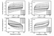
図2(a)は、実施例1で得られた電極のリニアスイープボルタンメトリー曲線を示している。図2(a)のリニアスイープボルタンメトリー曲線は、陽極として実施例1で得られた電極、陰極として白金板、参照電極としてAg/AgCl電極、電解液として1MのKOH水溶液を使用した酸素発生(OER)試験により得た。なお、図2(a)には比較として、実施例1で得られた電極を、比較例1、2で得られた電極及び未処理のNFにそれぞれ置き換えた場合の試験結果も示している。リニアスイープボルタンメトリー曲線を得るための測定装置は、標準3電極セルと共に米国VersaSTAT4 ポテンションスタットガルバノスタット電気化学ワークステーションを用いて測定を行った。 2(a) shows the linear sweep voltammetry curve of the electrode obtained in Example 1. FIG. The linear sweep voltammetry curve in Fig. 2(a) was obtained using the electrode obtained in Example 1 as the anode, the platinum plate as the cathode, the Ag/AgCl electrode as the reference electrode, and the 1 M KOH aqueous solution as the electrolyte (OER ) obtained by testing. For comparison, FIG. 2(a) also shows test results when the electrode obtained in Example 1 was replaced with the electrode obtained in Comparative Examples 1 and 2 and untreated NF, respectively. The measurement equipment for obtaining linear sweep voltammetry curves was performed using a US VersaSTAT4 potentiostat-galvanostat electrochemical workstation with a standard 3-electrode cell.
図2(b)は、図2(a)に示すリニアスイープボルタンメトリー曲線から算出したターフェル勾配を示している。図2(c)は、実施例1で得られた電極を陽極に用いて前記酸素発生試験を行った場合の水の定電流電解の結果であって、電流密度が100mA/cm2及び10mA/cm2それぞれにおける電位-時間グラフである。 FIG. 2(b) shows the Tafel slope calculated from the linear sweep voltammetry curve shown in FIG. 2(a). FIG. 2 (c) shows the results of constant-current electrolysis of water when the oxygen evolution test was performed using the electrode obtained in Example 1 as an anode. It is a potential-time graph in each cm 2 .
表1は、図2(a)から求めた各電極のOER過電圧(電流密度が10mA/cm2及び100mA/cm2の2種類)の結果を示している。 Table 1 shows the results of the OER overvoltage of each electrode (current densities of 10 mA/cm 2 and 100 mA/cm 2 ) obtained from FIG. 2(a).

図3(a)は、実施例1で得られた電極のリニアスイープボルタンメトリー曲線を示している。図3(a)のリニアスイープボルタンメトリー曲線は、陽極として白金板、陰極として実施例1で得られた電極、参照電極としてAg/AgCl電極、電解液として1MのKOH水溶液を使用した水素発生(HER)試験により得た。なお、図3(a)には比較として、実施例1で得られた電極を、比較例1、2で得られた電極及び未処理のNFにそれぞれ置き換えた場合の試験結果も示している。リニアスイープボルタンメトリー曲線を得るための測定装置は、標準3電極セルと共に米国VersaSTAT4 ポテンションスタットガルバノスタット電気化学ワークステーションを用いて測定を行った。 3(a) shows the linear sweep voltammetry curve of the electrode obtained in Example 1. FIG. The linear sweep voltammetry curve in Fig. 3(a) was obtained using a platinum plate as the anode, the electrode obtained in Example 1 as the cathode, an Ag/AgCl electrode as the reference electrode, and a 1 M KOH aqueous solution as the electrolyte (HER ) obtained by testing. For comparison, FIG. 3A also shows test results when the electrode obtained in Example 1 was replaced with the electrode obtained in Comparative Examples 1 and 2 and untreated NF, respectively. The measurement equipment for obtaining linear sweep voltammetry curves was performed using a US VersaSTAT4 potentiostat-galvanostat electrochemical workstation with a standard 3-electrode cell.
図3(b)は、図3(a)に示すリニアスイープボルタンメトリー曲線から算出したターフェル勾配を示している。図3(c)は、実施例1で得られた電極を陰極に用いて前記水素発生試験を行った場合の水の定電流電解の結果であって、電流密度が100mA/cm2及び10mA/cm2それぞれにおける電位-時間グラフである。
FIG. 3(b) shows the Tafel slope calculated from the linear sweep voltammetry curve shown in FIG. 3(a). FIG. 3(c) shows the results of constant current electrolysis of water when the hydrogen generation test was performed using the electrode obtained in Example 1 as the cathode, and the current densities were 100 mA/cm 2 and 10 mA/
表2は、図3(a)から求めた各電極のHER過電圧(電流密度が10mA/cm2及び100mA/cm2の2種類)の結果を示している。 Table 2 shows the results of HER overvoltage of each electrode (current densities of 10 mA/cm 2 and 100 mA/cm 2 ) obtained from FIG. 3(a).
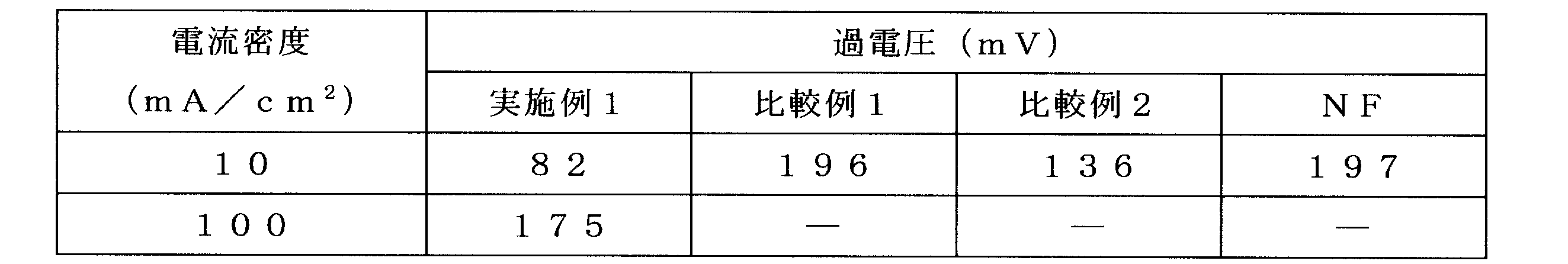
表1及び表2の結果から、実施例1で得られた電極を用いて水の電気分解を行った場合は、過電圧が抑制されていることがわかり、陽極及び陰極のいずれに使用した場合でも、過電圧が抑制されることがわかる。特に、実施例1で得られた電極は、公知の大半のNi系電極触媒と比べても低い値であることがわかった。 From the results in Tables 1 and 2, it was found that the overvoltage was suppressed when the electrode obtained in Example 1 was used to electrolyze water. , the overvoltage is suppressed. In particular, it was found that the electrode obtained in Example 1 had a lower value than most of the known Ni-based electrode catalysts.
図4は、実施例1で得られた電極を用いて水の電気分解を行った場合のクロノポテンシオメトリーの結果を示しており、(a)は実施例1で得られた電極を陽極として、(b)は実施例1で得られた電極を陰極として使用した場合の結果である(測定条件はそれぞれ前記酸素発生試験及び水素発生試験と同様とした)。測定条件はそれぞれリニアスイープボルタンメトリー曲線を得るための試験と同様の条件とし、測定装置は、2電極セルと共に米国VersaSTAT4 ポテンションスタットガルバノスタット電気化学ワークステーションを用いて測定を行った。 FIG. 4 shows the results of chronopotentiometry when water was electrolyzed using the electrode obtained in Example 1. (a) shows the electrode obtained in Example 1 as an anode. , (b) are the results when the electrode obtained in Example 1 was used as a cathode (measurement conditions were the same as those of the oxygen evolution test and the hydrogen evolution test, respectively). The measurement conditions were the same as those of the test for obtaining the linear sweep voltammetry curve, and the measurement was performed using a US VersaSTAT4 potentiostat galvanostat electrochemical workstation with a two-electrode cell.
図4において、10mA/cm2の電流密度での電位は、500秒間、1.45Vの一定値を示し、その後、220mA/cm2までに段階的に電流密度を上げても同様の傾向を示した。従って、得られた電極は酸素発生反応に対して良好な質量輸送特性および機械的堅牢性を有することがわかった。図4(b)は、10mA/cm2から300mA/cm2までの電極の多段階クロノポテンショメトリック曲線を示し、この図においても段階的に電流密度を上げても良好な電圧応答を示していることがわかる。従って、得られた電極は、水素発生試験に対しても優れた物質輸送特性と機械的堅牢性を備えていることがわかった。 In FIG. 4, the potential at a current density of 10 mA/cm 2 shows a constant value of 1.45 V for 500 seconds, and the same tendency is shown even if the current density is increased stepwise to 220 mA/cm 2 thereafter. rice field. Therefore, the resulting electrode was found to have good mass transport properties and mechanical robustness for the oxygen evolution reaction. FIG. 4(b) shows multi-step chronopotentiometric curves for electrodes from 10 mA/cm 2 to 300 mA/cm 2 , again showing good voltage response even with stepwise increasing current density. I understand. Therefore, it was found that the obtained electrode has excellent mass transport properties and mechanical robustness for the hydrogen evolution test.
図5は、各電極のCV曲線を示し、(a)はNF、(b)は比較例1の電極、(c)は比較例2の電極、(d)は実施例1の電極を使用した場合のCV曲線である。CV測定は、標準3電極セルと共に米国VersaSTAT4 ポテンションスタットガルバノスタット電気化学ワークステーションを用いて行った。CV測定では、電気化学的な活性表面積に関する電気化学的二重層キャパシタンスを、異なる走査速度で記録することによって、得られた電極の電気化学的な活性表面積を評価した。 FIG. 5 shows the CV curve of each electrode, (a) is NF, (b) is the electrode of Comparative Example 1, (c) is the electrode of Comparative Example 2, and (d) is the electrode of Example 1. CV curve for the case. CV measurements were performed using a US VersaSTAT4 potentiostat-galvanostat electrochemical workstation with a standard 3-electrode cell. In CV measurements, the electrochemically active surface area of the resulting electrodes was evaluated by recording the electrochemical double layer capacitance with respect to the electrochemically active surface area at different scanning speeds.
図5において、実施例1の電極は、6.31mF/cm2の最高電気化学的二重層キャパシタンスを有し、比較例1の電極(2.62mF/cm2)及び比較例2の電極(1.12mF/cm2)の2.4倍及び5.6倍近く向上した。この結果から、実施例1の電極は電気化学的な活性表面積が向上していることが実証された。花びら状の複合酸化物の表面に「コバルト及びニッケルの層状複水酸化物」の堆積によって、活性部位は大きな露出が達成されると考えられる。一般に、電気化学的な活性表面積が大きいことは、水分子の吸着に効果的である。実施例1の電極は、触媒活性をより確実に高める触媒反応の豊富な活性部位を提供することができ、電解質との接触性も向上するものと考えられる。 In FIG. 5, the electrode of Example 1 has the highest electrochemical double layer capacitance of 6.31 mF/cm 2 , the electrode of Comparative Example 1 (2.62 mF/cm 2 ) and the electrode of Comparative Example 2 (1 0.12 mF/cm 2 ), improved by a factor of 2.4 and nearly 5.6. This result demonstrated that the electrode of Example 1 had an improved electrochemically active surface area. It is believed that the deposition of the "layered double hydroxide of cobalt and nickel" on the surface of the petal-shaped composite oxide achieves a large exposure of the active sites. Generally, a large electrochemically active surface area is effective for adsorption of water molecules. It is believed that the electrode of Example 1 can provide abundant active sites for catalytic reactions that more reliably enhance catalytic activity, and also improve contact with the electrolyte.
図6は、実施例1で得られた電極のリニアスイープボルタンメトリー曲線を示している。図6のリニアスイープボルタンメトリー曲線は、陽極及び陰極ともに実施例1で得られた電極を、電解液として1MのKOH水溶液を使用して水の電気分解を行うことにより得た。図6より、電流密度が10mA/cm2である場合の電圧は1.62V、電流密度が100mA/cm2である場合の電圧は1.76Vであった。この結果は、実施例1で得られた電極が水の電気分解において両極に使用できること、及び、その際に優れた性能を有することを示している。 6 shows a linear sweep voltammetry curve of the electrode obtained in Example 1. FIG. The linear sweep voltammetry curve in FIG. 6 was obtained by electrolyzing water using the electrodes obtained in Example 1 for both the anode and cathode using a 1 M KOH aqueous solution as the electrolyte. From FIG. 6, the voltage was 1.62 V when the current density was 10 mA/cm 2 and the voltage was 1.76 V when the current density was 100 mA/cm 2 . This result indicates that the electrode obtained in Example 1 can be used as both electrodes in the electrolysis of water and has excellent performance in that case.
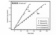
図7は、実施例1で得られた電極を両極に用いて水の電気分解を行った時の生成ガス量の経時変化を示している。図7中のプロットは実測値、実線は計算値を示す。 FIG. 7 shows changes over time in the amount of gas produced when water is electrolyzed using the electrodes obtained in Example 1 as both electrodes. Plots in FIG. 7 indicate measured values, and solid lines indicate calculated values.
実施例1で得られた電極をH字型セルの両極にセットして1MのKOH水溶液の電気分解を10mA/cm2の電流密度で行い、両極に生成した酸素及び水素ガスを定量したところ、電気量に対するガス収率は99%に達した。 The electrodes obtained in Example 1 were set at both electrodes of an H-shaped cell, and electrolysis of a 1 M KOH aqueous solution was performed at a current density of 10 mA/cm 2 , and oxygen and hydrogen gases generated at both electrodes were quantified. The gas yield to the amount of electricity reached 99%.
以上より、実施例1で得られた電極は、過電圧の上昇が起こりにくく、高い活性を有するので、水素を効率よく製造することができる触媒であるといえる。 From the above, it can be said that the electrode obtained in Example 1 is a catalyst capable of efficiently producing hydrogen because the electrode obtained in Example 1 is less likely to cause an increase in overvoltage and has high activity.
Claims (4)
前記工程1で焼成された電極基材を、第2のコバルト化合物及び金属M2の化合物(ここで、金属M2はFe、Ni、Cr、Cu、Zn、Mn及びMoからなる群より選ばれる少なくとも1種である。ただし、前記金属M2は、前記金属M1とは異なる金属である。)を含む溶液B中でパルス電着処理を行うことでコバルト及び前記金属M2を含有する層状複水酸化物を得る工程2と、
を具備し、
前記水熱合成は110~150℃で行われ、
前記層状複水酸化物は、複合酸化物表面を被覆するように形成されている、電極の製造方法。 a compound of metal M1 (here, metal M1 is at least one selected from the group consisting of Fe, Ni, Cr, Cu, Zn, Mn and Mo) and an electrode base material in solution A containing a first cobalt compound; Step 1 of obtaining a composite oxide containing Co and the metal M1 on the electrode substrate by taking out and baking the electrode substrate after hydrothermal synthesis in a state of being immersed;
The electrode base material fired in the step 1 is treated with a second cobalt compound and a compound of metal M2 (here, metal M2 is at least one selected from the group consisting of Fe, Ni, Cr, Cu, Zn, Mn and Mo. A layered double hydroxide containing cobalt and the metal M2 is formed by performing a pulse electrodeposition treatment in a solution B containing the metal M2, provided that the metal M2 is a metal different from the metal M1. Step 2 of obtaining
and
The hydrothermal synthesis is performed at 110 to 150 ° C.,
The method for producing an electrode , wherein the layered double hydroxide is formed so as to cover the surface of the composite oxide .
前記層状複水酸化物は、複合酸化物表面を被覆するように形成されている、電極。 A composite oxide containing Co and metal M1 (here, metal M1 is at least one selected from the group consisting of Fe, Ni, Cr, Cu, Zn, Mn and Mo) on an electrode substrate, cobalt and Metal M2 (Here, the metal M2 is at least one selected from the group consisting of Fe, Ni, Cr, Cu, Zn, Mn and Mo. However, the metal M2 is a metal different from the metal M1 ) is formed , and a layered double hydroxide containing
The electrode, wherein the layered double hydroxide is formed to cover the surface of the composite oxide .
Priority Applications (1)
| Application Number | Priority Date | Filing Date | Title |
|---|---|---|---|
| JP2018136041A JP7142862B2 (en) | 2018-07-19 | 2018-07-19 | Electrode manufacturing method, electrode and hydrogen manufacturing method |
Applications Claiming Priority (1)
| Application Number | Priority Date | Filing Date | Title |
|---|---|---|---|
| JP2018136041A JP7142862B2 (en) | 2018-07-19 | 2018-07-19 | Electrode manufacturing method, electrode and hydrogen manufacturing method |
Publications (2)
| Publication Number | Publication Date |
|---|---|
| JP2020012170A JP2020012170A (en) | 2020-01-23 |
| JP7142862B2 true JP7142862B2 (en) | 2022-09-28 |
Family
ID=69170350
Family Applications (1)
| Application Number | Title | Priority Date | Filing Date |
|---|---|---|---|
| JP2018136041A Active JP7142862B2 (en) | 2018-07-19 | 2018-07-19 | Electrode manufacturing method, electrode and hydrogen manufacturing method |
Country Status (1)
| Country | Link |
|---|---|
| JP (1) | JP7142862B2 (en) |
Families Citing this family (2)
| Publication number | Priority date | Publication date | Assignee | Title |
|---|---|---|---|---|
| CN111569884B (en) * | 2020-05-27 | 2022-11-11 | 上海科技大学 | Ni-Fe catalyst and preparation method and application thereof |
| CN112981452A (en) * | 2021-02-05 | 2021-06-18 | 深圳职业技术学院 | Water oxidation electrocatalyst and preparation method thereof, and water oxidation electrode and preparation method thereof |
Citations (3)
| Publication number | Priority date | Publication date | Assignee | Title |
|---|---|---|---|---|
| CN106807379A (en) | 2015-11-27 | 2017-06-09 | 中国科学院大连化学物理研究所 | A kind of flower ball-shaped nickel cobalt oxide oxygen-separating catalyst and its preparation method and application |
| WO2017154134A1 (en) | 2016-03-09 | 2017-09-14 | 国立大学法人弘前大学 | Method for manufacturing electrode for electrolysis of water |
| JP2017532189A (en) | 2014-08-11 | 2017-11-02 | ニューサウス・イノベーションズ・ピーティーワイ・リミテッド | Catalyst assembly |
-
2018
- 2018-07-19 JP JP2018136041A patent/JP7142862B2/en active Active
Patent Citations (3)
| Publication number | Priority date | Publication date | Assignee | Title |
|---|---|---|---|---|
| JP2017532189A (en) | 2014-08-11 | 2017-11-02 | ニューサウス・イノベーションズ・ピーティーワイ・リミテッド | Catalyst assembly |
| CN106807379A (en) | 2015-11-27 | 2017-06-09 | 中国科学院大连化学物理研究所 | A kind of flower ball-shaped nickel cobalt oxide oxygen-separating catalyst and its preparation method and application |
| WO2017154134A1 (en) | 2016-03-09 | 2017-09-14 | 国立大学法人弘前大学 | Method for manufacturing electrode for electrolysis of water |
Also Published As
| Publication number | Publication date |
|---|---|
| JP2020012170A (en) | 2020-01-23 |
Similar Documents
| Publication | Publication Date | Title |
|---|---|---|
| JP6406682B1 (en) | Electrode production method and hydrogen production method | |
| WO2017154134A1 (en) | Method for manufacturing electrode for electrolysis of water | |
| JP7353599B2 (en) | Electrode catalyst and its manufacturing method, and hydrogen manufacturing method | |
| JP7125707B2 (en) | Electrode manufacturing method, electrode and hydrogen manufacturing method | |
| JP2020070450A (en) | Electrode catalyst and production method thereof | |
| JP6498305B2 (en) | Anode for water electrolysis, electrolysis cell, and method for producing anode for water electrolysis | |
| JP5681343B2 (en) | Electrode for electrolysis | |
| JP6111125B2 (en) | Cathode electrode and electrolysis apparatus using the same | |
| TW201231727A (en) | Electrode for electrolysis, electrolytic cell and production method for electrode for electrolysis | |
| JP7142862B2 (en) | Electrode manufacturing method, electrode and hydrogen manufacturing method | |
| WO2019031753A1 (en) | Electrolytic electrode and manufacturing method therefor | |
| JP6978759B2 (en) | Gas diffusion layer for air electrode | |
| JP7344495B2 (en) | Method for producing VOC removal catalyst, VOC removal catalyst and VOC removal method | |
| JP6384887B2 (en) | Method for producing lead dioxide electrode | |
| JP2021030180A (en) | Production method of voc removal catalyst, voc removal catalyst, and voc removal method | |
| JP2022064166A (en) | Electrode catalyst, production method thereof, and hydrogen production method | |
| JP2008138282A (en) | Anode for alkaline electrolysis | |
| JP2020104083A (en) | Electrode catalyst, method for producing the same, and method for producing hydrogen | |
| CN108736029B (en) | Hollow sphere chain structure silver-platinum ruthenium composite material and application thereof in electrocatalytic oxidation of ethanol | |
| CN113242915A (en) | Electrode for electrolysis | |
| JP6878917B2 (en) | Electrode for hydrogen generation, its manufacturing method, and electrolysis method using it | |
| JP2010065311A (en) | Electrode for electrolysis | |
| JP2023119470A (en) | Oxygen generating electrode and method for producing the same, and oxygen generating electrode and method for electrolyzing water | |
| JP2019210541A (en) | Method of manufacturing electrode for generating hydrogen and electrolysis method using electrode for generating hydrogen | |
| WO2023189350A1 (en) | Electrolysis electrode and method for producing same |
Legal Events
| Date | Code | Title | Description |
|---|---|---|---|
| A621 | Written request for application examination |
Free format text: JAPANESE INTERMEDIATE CODE: A621 Effective date: 20210528 |
|
| A977 | Report on retrieval |
Free format text: JAPANESE INTERMEDIATE CODE: A971007 Effective date: 20220525 |
|
| A131 | Notification of reasons for refusal |
Free format text: JAPANESE INTERMEDIATE CODE: A131 Effective date: 20220607 |
|
| A521 | Request for written amendment filed |
Free format text: JAPANESE INTERMEDIATE CODE: A523 Effective date: 20220802 |
|
| TRDD | Decision of grant or rejection written | ||
| A01 | Written decision to grant a patent or to grant a registration (utility model) |
Free format text: JAPANESE INTERMEDIATE CODE: A01 Effective date: 20220830 |
|
| A61 | First payment of annual fees (during grant procedure) |
Free format text: JAPANESE INTERMEDIATE CODE: A61 Effective date: 20220905 |
|
| R150 | Certificate of patent or registration of utility model |
Ref document number: 7142862 Country of ref document: JP Free format text: JAPANESE INTERMEDIATE CODE: R150 |