JP7140980B2 - rotary reciprocating drive actuator - Google Patents
rotary reciprocating drive actuator Download PDFInfo
- Publication number
- JP7140980B2 JP7140980B2 JP2019225570A JP2019225570A JP7140980B2 JP 7140980 B2 JP7140980 B2 JP 7140980B2 JP 2019225570 A JP2019225570 A JP 2019225570A JP 2019225570 A JP2019225570 A JP 2019225570A JP 7140980 B2 JP7140980 B2 JP 7140980B2
- Authority
- JP
- Japan
- Prior art keywords
- drive actuator
- magnet
- reciprocating drive
- rotary reciprocating
- movable magnet
- Prior art date
- Legal status (The legal status is an assumption and is not a legal conclusion. Google has not performed a legal analysis and makes no representation as to the accuracy of the status listed.)
- Active
Links
Images


Classifications
-
- G—PHYSICS
- G02—OPTICS
- G02B—OPTICAL ELEMENTS, SYSTEMS OR APPARATUS
- G02B26/00—Optical devices or arrangements for the control of light using movable or deformable optical elements
- G02B26/08—Optical devices or arrangements for the control of light using movable or deformable optical elements for controlling the direction of light
- G02B26/10—Scanning systems
- G02B26/105—Scanning systems with one or more pivoting mirrors or galvano-mirrors
-
- H—ELECTRICITY
- H02—GENERATION; CONVERSION OR DISTRIBUTION OF ELECTRIC POWER
- H02K—DYNAMO-ELECTRIC MACHINES
- H02K33/00—Motors with reciprocating, oscillating or vibrating magnet, armature or coil system
- H02K33/12—Motors with reciprocating, oscillating or vibrating magnet, armature or coil system with armatures moving in alternate directions by alternate energisation of two coil systems
-
- H—ELECTRICITY
- H02—GENERATION; CONVERSION OR DISTRIBUTION OF ELECTRIC POWER
- H02K—DYNAMO-ELECTRIC MACHINES
- H02K33/00—Motors with reciprocating, oscillating or vibrating magnet, armature or coil system
- H02K33/18—Motors with reciprocating, oscillating or vibrating magnet, armature or coil system with coil systems moving upon intermittent or reversed energisation thereof by interaction with a fixed field system, e.g. permanent magnets
-
- H—ELECTRICITY
- H02—GENERATION; CONVERSION OR DISTRIBUTION OF ELECTRIC POWER
- H02K—DYNAMO-ELECTRIC MACHINES
- H02K11/00—Structural association of dynamo-electric machines with electric components or with devices for shielding, monitoring or protection
- H02K11/20—Structural association of dynamo-electric machines with electric components or with devices for shielding, monitoring or protection for measuring, monitoring, testing, protecting or switching
- H02K11/21—Devices for sensing speed or position, or actuated thereby
- H02K11/22—Optical devices
Description
本発明は、回転往復駆動アクチュエーターに関する。 The present invention relates to rotary reciprocating drive actuators.
例えば、複合機、レーザービームプリンタ等のスキャナーに回転駆動アクチュエーターが使用されている。具体的には、回転往復駆動アクチュエーターは、スキャナーのミラーを往復回転させることで、レーザー光の反射角度を変更して対象物に対する光走査を実現する。 For example, rotary drive actuators are used in scanners such as multifunction devices and laser beam printers. Specifically, the rotary reciprocating drive actuator reciprocates the mirror of the scanner to change the reflection angle of the laser light, thereby achieving optical scanning of the object.
従来、この種の回転往復駆動アクチュエーターとしてガルバノモーターを用いたものが、特許文献1、2等に開示されている。ガルバノモーターとしては、コイルをミラーに取り付けたコイル可動タイプの他、特許文献1に開示された構造等の様々なタイプのものが知られている。
Conventionally,
因みに、特許文献1には、4つの永久磁石が、ミラーが取り付けられる回転軸に、回転軸径方向に着磁するように設けられ、コイルが巻回された磁極を有するコアが、回転軸を挟むように配置されたビームスキャナが開示されている。
Incidentally, in
ところで、コイル可動タイプの回転往復駆動アクチュエーターにおいては、駆動時のコイルの発熱により、ミラーの表面状態、回転軸へのミラーの接合状態、反りを含むミラーの形状等に悪影響を与えるおそれがある。また、コイル可動タイプの回転往復駆動アクチュエーターにおいては、通電時のコイルの発熱を考慮するとコイルへの入力電流も大きくしにくく、可動体であるミラーの大型化や高振幅化が困難であるという問題がある。さらに、可動体であるミラーに対して、コイルへの配線を固定体側に引き出す必要があり組み立て性が悪いという問題がある。 Incidentally, in a coil-moving type rotary reciprocating actuator, the heat generated by the coil during driving may adversely affect the surface condition of the mirror, the joining condition of the mirror to the rotating shaft, the shape of the mirror including warpage, and the like. In addition, in the moving coil type rotary reciprocating actuator, it is difficult to increase the input current to the coil when considering the heat generated by the coil when energized, and it is difficult to increase the size and amplitude of the mirror, which is the movable body. There is Furthermore, there is a problem that the wiring to the coil needs to be pulled out to the fixed body side of the mirror, which is a movable body, and the assembly is difficult.
また、特許文献1では、マグネットを可動体側に配置しているので、上述したコイル可動タイプでの問題を解消できるものの、マグネットをコアに対して中立位置に静止させる、つまり、マグネットの磁極の切り替わり部をコアのセンターに位置させるために、コア1極あたりに2極のマグネット、合計で、4極のマグネットが必要である。
Further, in
これにより、例えば、2極のマグネットを用いて同様の回転往復駆動アクチュエーターを構成する場合と比較して、可動体の振幅が小さくなる、つまり、揺動範囲が減少するという問題がある。また、少なくとも4つのマグネットを用いるので、部品点数が多く複雑な構成であり組立が難しい。 As a result, there is a problem that the amplitude of the movable body is smaller, that is, the swing range is reduced, compared to the case of configuring a similar rotary reciprocating actuator using a two-pole magnet, for example. In addition, since at least four magnets are used, the number of parts is large and the configuration is complicated, making assembly difficult.
さらに、近年、スキャナーに用いられる回転往復駆動アクチュエーターとして、可動体であるミラーの大型化等を想定して、剛性を備え、耐衝撃性、耐振動性を有するとともに、組み立て性の向上が図られ、高振幅化を実現可能な回転往復駆動アクチュエーターが望まれている。 Furthermore, in recent years, assuming that mirrors, which are movable bodies, have become larger in size, etc., as rotary reciprocating drive actuators used in scanners, efforts have been made to improve the assembly efficiency as well as to provide rigidity, shock resistance, and vibration resistance. , a rotary reciprocating drive actuator capable of achieving high amplitude is desired.
さらに、回転往復駆動アクチュエーターにおいては、特許文献1にも記載されているように、ミラーに接続された回転軸の回転角度を検出する角度センサーが設けられる。スキャナーとしてのスキャン精度は、この角度センサーの検知精度に大きく依存する。角度センサーの検知精度を高めるためには、角度センサーと、ミラー等の回転往復駆動アクチュエーターの他の構成部品との相対関係が決まった関係となるように、高精度で角度センサーの組み付け位置を調整する必要がある。このような要求は、回転往復駆動アクチュエーターの組み立てを難しくしている。
Further, in the rotary reciprocating drive actuator, as described in
本発明は、以上の点を考慮してなされたものであり、組み立てが容易であり、かつ、可動対象を高振幅で駆動できる回転往復駆動アクチュエーターを提供する。 SUMMARY OF THE INVENTION The present invention has been made in consideration of the above points, and provides a rotary reciprocating actuator that is easy to assemble and that can drive a movable object with high amplitude.
本発明の回転往復駆動アクチュエーターの一つの態様は、
底部と、前記底部の両端から、それぞれの内側面を互いに対向させて立設された一対の壁部と、を有するベース部と、
両端部のうち一端部の外周に可動マグネットが固定され、前記両端部間の中間部に可動対象物の装着が可能な軸部を有し、前記中間部が前記一対の壁部の内側に配置され、且つ、前記可動マグネットが前記一対の壁部のうち一方の壁部の外面側に配置された状態で、前記軸部が軸受けを介して前記一対の壁部に回転自在に支持された、可動体と、
前記可動マグネットを挟むように前記可動マグネットの外周に対向する偶数の磁極を有するコア体と、前記コア体に巻回され、前記可動マグネットと相互作用する磁束を通電により発生して前記可動体を往復回転させるコイル体と、前記可動マグネットとの間に磁気吸引力を発生して前記往復回転の基準位置を規定するマグネット位置保持部と、を有し、前記外面側で前記一方の壁部に取り付けられた駆動ユニットと、
前記一対の壁部のうちの他方の壁部に取り付けられ、前記軸部の回転角度を検知する角度センサー部と、
を備える。
One aspect of the rotary reciprocating drive actuator of the present invention is
a base portion having a bottom portion and a pair of wall portions erected from both ends of the bottom portion with their inner surfaces facing each other ;
A movable magnet is fixed to the outer circumference of one of both ends, and a shaft portion on which a movable object can be attached is provided in an intermediate portion between the both ends, and the intermediate portion is arranged inside the pair of wall portions. and the shaft portion is rotatably supported by the pair of wall portions via bearings in a state in which the movable magnet is arranged on the outer surface side of one of the pair of wall portions, a movable body;
a core body having an even number of magnetic poles facing the outer periphery of the movable magnet so as to sandwich the movable magnet; It has a coil body that reciprocates and a magnet position holding section that generates a magnetic attraction force between the movable magnet and defines a reference position for the reciprocating rotation, and is attached to the one wall section on the outer surface side. a mounted drive unit;
an angle sensor unit attached to the other wall portion of the pair of wall portions and detecting the rotation angle of the shaft portion;
Prepare.
本発明によれば、可動マグネットを基準位置に磁気吸引するマグネット位置保持部を設けたことにより、可動対象が大型ミラーであっても高振幅で駆動できるようになる。また、角度センサー部が、一対の壁部のうちの駆動ユニットが取り付けられた壁部に対する他方の壁部に取り付けられているので、組み立てが容易となる。 According to the present invention, by providing the magnet position holding section that magnetically attracts the movable magnet to the reference position, even if the movable object is a large mirror, it can be driven with high amplitude. In addition, since the angle sensor section is attached to the other wall portion of the pair of wall portions with respect to the wall portion to which the drive unit is attached, assembly is facilitated.
以下、本発明の実施の形態を、図面を参照して説明する。 BEST MODE FOR CARRYING OUT THE INVENTION Hereinafter, embodiments of the present invention will be described with reference to the drawings.
<1>回転往復駆動アクチュエーターの全体構成
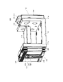
図1は、実施の形態の回転往復駆動アクチュエーター100の外観斜視図である。図2は、回転往復駆動アクチュエーター100の分解斜視図である。
<1> Overall Configuration of Reciprocating Rotary Drive Actuator FIG. 1 is an external perspective view of a reciprocating
回転往復駆動アクチュエーター100は、例えばライダー(LIDAR:Laser Imaging Detection and Ranging)装置に用いられる。なお、回転往復駆動アクチュエーター100は、複合機、レーザービームプリンタ等のスキャナーにも適用可能である。
The rotary reciprocating
回転往復駆動アクチュエーター100は、大きく分けて、ベース部110と、ベース部110に回転自在に支持されるミラー部120と、ミラー部120を往復回転駆動する駆動ユニット200と、ミラー部120の回転角度位置を検出する角度センサー部130と、を有する。
The rotary reciprocating
ミラー部120は、図2から分かるように、基板122の一面にミラー121が貼り付けられている。基板122の挿通孔122aには軸部141が挿通され、基板122と軸部141は固着される。
As can be seen from FIG. 2, the
ベース部110は、一対の壁部111a、111bを有する断面が略コ字状の部材でなる。一対の壁部111a、111bにはそれぞれ軸部141が挿通される挿通孔112が形成されている。さらに、一対の壁部111a、111bにはそれぞれ挿通孔112と壁部111a、111bの外縁とを連通する切欠穴113が形成されている。
The
これにより、軸部141にミラー部120を固着させた状態で、軸部141を切欠穴113を介して挿通孔112の位置に配置させることができる。切欠穴113が無い場合には、一対の壁部111a、111bの間にミラー部120を配置させた状態で、軸部141を壁部111a、111bの挿通孔112及び基板122の挿通孔122aの両方に挿通し、さらに軸部141と基板122を固着させるといった煩雑な組立て作業が必要となる。これに対して、本実施の形態においては、切欠穴113を形成したので、予めミラー部120を固着させた軸部141を、簡単に挿通孔112に挿通させることができるようになる。
Thereby, the
軸部141の両端にはボールベアリング151が取り付けられる。ボールベアリング151は、一対の壁部111a、111bの挿通孔112の位置に形成されたベアリング取付部114に取り付けられる。これにより、軸部141は、ボールベアリング151を介して回転自在にベース部110に取り付けられ、一対の壁部111a、111bの間には、可動対象物であるミラー部120が配置される。
さらに、軸部141の一端には可動マグネット161が固着される。可動マグネット161は、駆動ユニット200内に配置され、駆動ユニット200により発生される磁束によって往復回転駆動される。
Furthermore, a
このように、本実施の形態では、可動対象物であるミラー部120が取り付けられる軸部141は、ベース部110の一対の壁部111a、111bによって、ミラー部120を両側から支持するように軸支されている。これにより、軸部141を片持ちで軸支するよりもミラー部120の支持が強固となり、耐衝撃性や耐振動性が高まる。
Thus, in the present embodiment, the
駆動ユニット200は、図2から分かるように、コア体210と、コイル体220と、を有する。コイル体220の内部にはコイルが巻回して設けられている。コア体210は、第1コア体211と第2コア体212とからなる。同様に、コイル体220は、第1コイル体221と第2コイル体222とからなる。コイル体220は、コア体210の一部に差し込むようにして取り付けられる。これにより、コイル体220のコイルが通電されると、コア体210が励磁される。
The
コア体210及びコイル体220は、固定プレート250に固定され、固定プレート250は、止着材251を介してベース110の壁部111aに固定される。
The
因みに、本実施の形態の例では、駆動ユニット200は、さらに、架設コア230と、マグネット位置保持部240と、を有する。架設コア230は、コア体210と同様の構成である。マグネット位置保持部240は、マグネットにより構成されている。マグネット位置保持部240の磁力によって可動マグネット161の位置が動作基準位置に磁気吸引される。このことについては、後で詳述する。
Incidentally, in the example of the present embodiment, the
本実施の形態の例では、コア体210及び架設コア230は、それぞれ積層コアであり、例えば、ケイ素鋼板を積層して構成されている。
In the example of the present embodiment, the
角度センサー部130は、回路基板131と、回路基板131に実装された光センサー132及びコネクター133と、エンコーダーディスク134と、ケース135と、を有する。回路基板131は止着材136によりケース135に固定される。ケース135は止着材137により壁部111bに固定される。
The
エンコーダーディスク134は、取付材138を介して軸部141に固着して取り付けられ、可動マグネット161及びミラー部120と一体に回転する。つまり、取付材138は、軸部141が挿通されて固着される挿通孔と、エンコーダーディスク134が当接されて固着されるフランジ部とを有し、軸部141とエンコーダーディスク134との両方に固定される。この結果、エンコーダーディスク134の回転位置が軸部141の回転位置と同一となる。光センサー132は、エンコーダーディスク134に光を出射しその反射光に基づいてエンコーダーディスク134の回転位置(角度)を検出する。これにより、光センサー132によって可動マグネット161及びミラー部120の回転位置を検出できる。
The
本実施の形態の回転往復駆動アクチュエーター100においては、可動マグネット161や軸部141を有する可動体、コイル体220及びコア体210などを有する駆動ユニット200は、ベース部110の一対の壁部111a、111bのうちの一方の壁部111aの外面側に取り付けられる。これに対して、軸部141の回転角度を検知する角度センサー部130は、ベース部110の一対の壁部111a、111bのうちの他方の壁部111bの外面側に取り付けられている。
In the rotary
これにより、角度センサー部130の取り外しや組み付け位置の調整が容易となる。角度センサー部130の取り外しが容易となることにより、角度センサー部130に不具合が生じた場合に容易に交換できるようになる。また、角度センサー部130の組み付けを組み立ての最終段階で行うことが可能となる。この結果、他の部品の組み立てが正常であることを確認してから高価な角度センサー部130を組み付けることができるので、高価な角度センサー部130を他の部品の組み立て不良が原因で無駄にするといったリスクを抑制することができる。
This facilitates removal of the
<2>回転往復駆動アクチュエーターの詳細構成及び動作
次に、回転往復駆動アクチュエーター100の詳細構成及び動作について、図3-図5を用いて説明する。
<2> Detailed Configuration and Operation of Reciprocating Rotary Drive Actuator Next, the detailed configuration and operation of the reciprocating
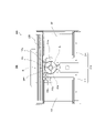
図3は、図1の回転往復駆動アクチュエーター100を図1の左側から見た側面図である。つまり、図3では、主に、駆動ユニット200が示されている。
FIG. 3 is a side view of the rotary
回転往復駆動アクチュエーター100においては、マグネット位置保持部240と可動マグネット161との磁気吸引力、所謂、磁気バネにより、常態時では、可動マグネット161や軸部141などからなる可動体は、動作基準位置に位置するように、回動自在に保持されている。ここで、常態時は、コイル体220に通電されていない状態である。
In the rotary
可動体が動作基準位置に位置することは、本実施の形態では、可動マグネット161がコイル体220の励磁するコア体210の磁極211a、212aに対して中立な位置に位置することを意味し、軸回りの一方向と他方向(軸部141側から見て正転及び逆転)の双方のいずれの方向にも同様に回転が可能な位置である。換言すれば、マグネット位置保持部240が可動マグネット161を磁気吸引する基準位置は、可動マグネット161の往復回転の回転中心位置である。可動体が動作基準位置に位置するとき、可動マグネット161の磁極の切り替わり部161cが、コイル体220側の磁極と対向する位置に位置する。
Positioning the movable body at the operation reference position means that the
可動マグネット161とコイル体220との協働により、可動体の軸部141は、ベース部110に対して動作基準位置から軸回りの一方向と他方向とに往復回転する。
Due to cooperation between the
可動マグネット161は、リング形状をなしており、軸部141の外周で、軸部141の回転軸方向と直交する方向に、S極及びN極が交互に着磁された偶数の磁極161a、161bを有する。可動マグネット161は、本実施の形態では、2極に着磁されているが、可動時の振幅に応じて2極以上着磁されていてもよい。
The
偶数の磁極161a、161bは、軸部141を挟み互いに反対側に向く異なる極性の着磁面を有する。本実施の形態では、磁極161a、161bは、軸部141の軸方向に沿う平面を境界として異なる極性である。
The even-numbered
また、偶数の磁極161a、161bは、軸部141の外周で、等間隔に着磁されて構成されている。
The even-numbered
このように可動マグネット161では、軸部141の外周に、S極及びN極をなす偶数の磁極161a、161bが交互に配置され、かつ、それぞれの磁極161a、161bは等間隔に配置されている。
In this manner, in the
より具体的には、可動マグネット161は、それぞれの半円状の部位が異なる磁極161a、161bを構成している。半円状の部位の円弧状の湾曲面が、異なる磁極161a、161bの着磁面であり、この異なる磁極161a、161bの着磁面が軸回りに周方向に延在するように構成されている。言い換えれば、磁極161a、161bの着磁面は、軸部141の軸方向と直交する方向に並び、且つ、回転してそれぞれ第1コア体211、第2コア体212の磁極211a、212aに対向可能に配置される。
More specifically, the
可動マグネット161の磁極数は、コア体210の磁極数と等しい。
The number of magnetic poles of
可動マグネット161の磁極161a、161bの磁極切り替わり部161cは、コイル体220への非通電時において、第1コア体211、第2コア体212の磁極211a、212aの幅方向の中心位置と対向する位置に位置する。
The magnetic
第1コア体211、第2コア体212は、互いに平行であり、かつ、可動マグネット161を挟むように形成された芯部211b、212b(図4参照)を有する。芯部211b、212bには、それぞれ、第1コイル体221、第2コイル体222が外挿されている。芯部211b、212bの一方の端部間に架設コア230が架設され、芯部211b、212bの他方の端部に連続して磁極211a、212aが形成されている。
The
このように、コア体210は、コイル体221、222が外挿される芯部211b、212bと、磁極211a、212aと、磁極211a、212aとは反対側の端部間に架設される架設コア230と、を有する。すなわち、コア体210は3つの分割体により構成されている。これら分割体のうち、架設コア230にマグネット位置保持部240が設けられている。
In this way, the
2つの磁極211a、212aは、可動マグネット161の外周とエアギャップGを空けて可動マグネット161を挟むように対向して配置される。
The two
架設コア230には、可動マグネット161にエアギャップGを空けて対向して配置されるマグネット位置保持部240が、可動マグネット161側に凸状に突出して取り付けられている。
A magnet
マグネット位置保持部240は、例えば、対向面をN極(図4参照)に着磁されたマグネットである。マグネット位置保持部240は、架設コア230と一体的に形成されていてもよい。
The magnet
マグネット位置保持部240は、可動マグネット161との間に発生する磁気吸引力により、可動マグネット161とともに磁気バネとして機能し、回転する可動マグネット161の位置を動作基準位置に位置させて保持する。
The magnet
マグネット位置保持部240は、可動マグネット161側に向けて着磁されたマグネットである。マグネット位置保持部240は、動作基準位置において、可動マグネット161の磁極切り替わり部161cを、磁極211a、212aと対向する位置に位置させる。このように、マグネット位置保持部240は、可動マグネット161と互いに吸引し合い、可動マグネット161を動作基準位置に位置させることができる。これにより、可動マグネット161の磁極切り替わり部161cが、第1コア体211、第2コア体212の磁極211a、212aと対向する。この位置で、駆動ユニット200は最大トルクを発生して可動体を安定して駆動する。
The magnet
また、可動マグネット161は、2極着磁されているので、コア体210との協働により、可動対象物を高振幅で駆動しやすくなるとともに、振動性能の向上を図ることができる。
In addition, since the
図4及び図5は、回転往復駆動アクチュエーター100の磁気回路の動作の説明に供する図である。
4 and 5 are diagrams for explaining the operation of the magnetic circuit of the rotary
コイル体220(221、222)への非通電時において、可動マグネット161は、マグネット位置保持部240と可動マグネット161との磁気吸引力、つまり、磁気ばねにより動作基準位置に位置する。
When the coil body 220 (221, 222) is not energized, the
この動作基準位置(以下、動作基準位置を常態時と呼ぶこともある)では、可動マグネット161の磁極161a、161bの一方がマグネット位置保持部240に吸引されて、磁気切り替わり部161cが、第1コア体211、第2コア体212の磁極211a、212aの中心位置と対向する位置に位置する。
At this operation reference position (hereinafter, the operation reference position may be referred to as the normal state), one of the
コイル体220に通電が行われると、コイル体220(221、222)は、第1コア体211、第2コア体212を励磁する。
When the
図4に示す方向でコイル体220が通電されると、磁極211aはN極に磁化され、磁極212aはS極に磁化される。
When the
この結果、第1コア211では、N極に磁化された磁極211aから可動マグネット161に出射して、可動マグネット161、マグネット回転位置保持部240、架設コア230を順に流れ、芯部211bに入射する磁束が形成される。
As a result, in the
また、第2コア212では、磁束は、芯部212bから架設コア230側に出射して、架設コア230、マグネット回転位置保持部240、可動マグネット161を順に流れ、磁極212aに入射する。
Further, in the
これにより、N極に磁化された磁極211aは、可動マグネット161のS極と引き合い、S極に磁化された磁極212aは、可動マグネット161のN極と引き合い、可動マグネット161には軸部141の軸回りにF方向のトルクが発生し、可動マグネット161はF方向に回転する。これに伴い、軸部141も回転し、軸部141に固定されるミラー部120も回転する。
As a result, the
次に、図5に示したように、コイル体220の通電方向が逆方向に切り替わると、磁極211aはS極に磁化され、磁極212aはN極に磁化され、磁束の流れも逆になる。
Next, as shown in FIG. 5, when the energization direction of the
これにより、S極に磁化された磁極211aは、可動マグネット161のN極と引き合い、N極に磁化された磁極212aは、可動マグネット161のS極と引き合い、可動マグネット161には軸部141の軸回りにF方向とは逆回りの方向のトルクが発生し、可動マグネット161はF方向とは逆の方向に回転する。これに伴い、軸部141も逆方向に回転し、軸部141に固定されるミラー部120も先の回転方向とは逆方向に回転する。回転往復駆動アクチュエーター100は、これを繰り返すことで、ミラー部120を往復回転駆動する。
As a result, the
実際上、回転往復駆動アクチュエーター100は、電源供給部(例えば図7の駆動信号供給部21に相当)からコイル体220に入力される交流波によって駆動される。つまり、コイル体220の通電方向は周期的に切り替わり、可動体には、軸回りのF方向のトルクと、F方向とは逆の方向(-F方向)のトルクが交互に作用する。これにより、可動体は、往復回転駆動される。
In practice, the rotary
因みに、通電方向の切り替わり時には、マグネット回転位置保持部240と可動マグネット161との間の磁気吸引力、つまり磁気バネにより、磁気バネトルクFM(図4)又は-FM(図5)が発生し可動マグネット161は動作基準位置に付勢される。
Incidentally, when the energization direction is switched, a magnetic spring torque FM (FIG. 4) or −FM (FIG. 5) is generated by the magnetic attraction force between the magnet rotation
以下に、回転往復駆動アクチュエーター100の駆動原理について簡単に説明する。本実施の形態の回転往復駆動アクチュエーター100では、可動体の慣性モーメントをJ[kg・m2]、磁気バネ(磁極211a、212a、マグネット位置保持部240及び可動マグネット161)のねじり方向のバネ定数をKspとした場合、可動体は、ベース部110に対して、式(1)によって算出される共振周波数Fr[Hz]で振動(往復回転)する。
The drive principle of the rotary

可動体は、バネ-マス系の振動モデルにおけるマス部を構成するので、コイル体220に可動体の共振周波数Frに等しい周波数の交流波が入力されると、可動体は共振状態となる。すなわち、電源供給部からコイル体220に対して、可動体の共振周波数Frと略等しい周波数の交流波を入力することにより、可動体を効率良く振動させることができる。
Since the movable body constitutes a mass portion in the vibration model of the spring-mass system, when an AC wave having a frequency equal to the resonance frequency Fr of the movable body is input to the
回転往復駆動アクチュエーター100の駆動原理を示す運動方程式及び回路方程式を以下に示す。回転往復駆動アクチュエーター100は、式(2)で示す運動方程式及び式(3)で示す回路方程式に基づいて駆動する。
Equations of motion and circuit equations showing the driving principle of the rotary


すなわち、回転往復駆動アクチュエーター100における可動体の慣性モーメントJ[kg・m2]、回転角度θ(t)[rad]、トルク定数Kt[N・m/A]、電流i(t)[A]、バネ定数Ksp[N・m/rad]、減衰係数D[N・m/(rad/s)]、負荷トルクTLoss[N・m]等は、式(2)を満たす範囲内で適宜変更できる。また、電圧e(t)[V]、抵抗R[Ω]、インダクタンスL[H]、逆起電力定数Ke[V/(rad/s)]は、式(3)を満たす範囲内で適宜変更できる。
That is, the inertia moment J [kg·m 2 ] of the movable body in the rotary
このように、回転往復駆動アクチュエーター100は、可動体の慣性モーメントJと磁気ばねのバネ定数Kspにより決まる共振周波数Frに対応する交流波によりコイルへの通電を行った場合に、効率的に大きな振動出力を得ることができる。
In this way, the rotary
本実施の形態の回転往復駆動アクチュエーター100によれば、トルクの発生効率が高いので、可動対象であるミラー121に熱が伝達しにくく、この結果、ミラー121の反射面の平面度の精度を確保できる。また、製造性が高く、組立精度がよく、可動対象が大型ミラーであっても高振幅で駆動できる。
According to the rotary
なお、本実施の形態の回転往復駆動アクチュエーター100は、共振駆動が可能であるが、非共振駆動も可能である。
It should be noted that the rotary
<3>スキャナーシステムの概略構成
次に、回転往復駆動アクチュエーター100を用いたスキャナーシステムの構成について簡単に説明する。
<3> Schematic Configuration of Scanner System Next, the configuration of a scanner system using the rotary
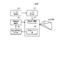
図6は、回転往復駆動アクチュエーター100を用いたスキャナーシステム300Aの要部構成を示すブロック図である。
FIG. 6 is a block diagram showing the main configuration of a
スキャナーシステム300Aは、回転往復駆動アクチュエーター100に加えて、レーザー発光部301、レーザー制御部302、駆動信号供給部303及び位置制御信号計算部304を有する。
The
レーザー発光部301は、例えば、光源となるLD(レーザーダイオード)と、この光源から出力されるレーザー光を収束するためのレンズ系などで構成される。レーザー制御部302は、レーザー発光部301を制御する。レーザー発光部301で得られたレーザー光は、回転往復駆動アクチュエーター100のミラー121に入射される。
The
位置制御信号計算部304は、角度センサー部130により取得された軸部141(ミラー121)の角度位置と、目標角度位置とを参照して、軸部141(ミラー121)を目標角度位置となるように制御する駆動信号を生成して出力する。例えば、位置制御信号計算部304は、取得した軸部141(ミラー121)の角度位置と、図示しない波形メモリに格納されているのこぎり波形データ等を用いて変換された目標角度位置を示す信号とに基づいて位置制御信号を生成して、この位置制御信号を駆動信号供給部303に出力する。
The position
駆動信号供給部303は、位置制御信号に基づいて、回転往復駆動アクチュエーター100のコイル体220に、軸部141(ミラー121)の角度位置が所望の角度位置となるような駆動信号を供給する。これにより、スキャナーシステム300Aは、回転往復駆動アクチュエーター100から所定の走査領域に走査光を出射することができる。
Based on the position control signal, the drive
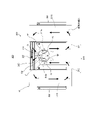
図1との対応部分に同一符号を付して示す図7は、スキャナーシステムの構成例を示す外観斜視図である。スキャナーシステム300Cは、ベース部110上にレーザーユニット410が設けられている。レーザーユニット410は、レーザー発光部411及びレーザー受光部412を有する。これにより、レーザー発光部411から出射されたレーザー光が、回転往復駆動アクチュエーター100のミラー部120で反射して走査光とされ、走査対象に照射される。走査対象で反射した走査光は、ミラー部120を介してレーザー受光部412で受光される。なお、スキャナーシステム300Cの回転往復駆動アクチュエーター100においては、図1の回転往復駆動アクチュエーター100と比較して、ベース部110の底板が図中の奥行方向に拡張されており、この拡張部分にレーザーユニット410が設置されている。
FIG. 7, in which parts corresponding to those in FIG. 1 are denoted by the same reference numerals, is an external perspective view showing a configuration example of the scanner system. The
図7との対応部分に同一符号を付して示す図8は、スキャナーシステムの別の構成例を示す外観斜視図である。スキャナーシステム300Dは、レーザーユニット410の配設位置が異なることを除いてスキャナーシステム300Cと同様の構成でなる。
FIG. 8, in which parts corresponding to those in FIG. 7 are denoted by the same reference numerals, is an external perspective view showing another configuration example of the scanner system. The
図7及び図8に示したように、回転往復駆動アクチュエーター100のベース部110に、レーザーユニット410を設けたことにより、回転往復駆動アクチュエーター100に容易かつ精度良くレーザーユニット410を取り付けることができる。
As shown in FIGS. 7 and 8, by providing the
ここで、スキャナーとしての機能を実現するのであれば、レーザーユニット410は、レーザー受光部412を有さずに、レーザー発光部411のみを有していてもよい。ただし、本実施の形態では、レーザーユニット410がレーザー受光部412も有し、さらに、レーザーユニット410が回転往復駆動アクチュエーター100のベース部110に設けられているので、結果として、光検出部であるレーザー受光部412がスキャナー部分に直接取り付けられた構成となる。これにより、スキャナー部分に対するレーザー受光部の位置決め精度を容易に高めることができる。
Here, the
<4>まとめ
以上説明したように、本実施の形態の回転往復駆動アクチュエーター100は、ベース部110と、可動対象物(実施の形態の例ではミラー部120)が接続される軸部141に固定された可動マグネット161と、コア体210、及び、通電時にコア体210に磁束を発生させるコイル体220を有し、コア体210から発生する磁束と可動マグネット161との電磁相互作用により、可動マグネット161を往復回転駆動する駆動ユニット200と、を有する。さらに、回転往復駆動アクチュエーター100は、可動マグネット161は、リング形状を成し、軸部141の外周で、S極及びN極を成す偶数の磁極が交互に着磁されて構成され、コア体210の磁極数と可動マグネット161の磁極数は、等しく、コア体210の偶数の磁極は、可動マグネット161と、軸部141の外周側でエアギャップを挟み各々対向して配置され、駆動ユニット200には、可動マグネット161に対向して設けられた磁性体であり、可動マグネット161を基準位置に磁気吸引するマグネット位置保持部240が設けられている。
<4> Summary As described above, the rotary
これにより、可動マグネット161がマグネット位置保持部240によって、通電方向の切り替わる度に中立位置(動作基準位置)に磁気吸引されるので、エネルギー効率が良く、応答性が良く、かつ高振幅の往復回転駆動が実現される。また、コイル可動タイプの回転往復駆動アクチュエーターと比較して、コイル体220での発熱が可動対象物に伝わりにくく、可動対象物がミラーである場合に、ミラーに熱による悪影響(接合劣化、反りなど)が及ぶことを回避できる。
As a result, the
加えて、本実施の形態の回転往復駆動アクチュエーター100は、ベース部110には、軸受け(ボールベアリング151)を介して軸部141を回転自在に支持する一対の壁部111a、111bが立設されており、一対の壁部111a、111bの間には、可動対象物(実施の形態の例ではミラー部120)が配置され、駆動ユニット200は、一対の壁部111a、111bのうちの一方の壁部111aの外面側に取り付けられ、軸部141の回転角度を検知する角度センサー部130は、一対の壁部111a、111bのうちの他方の壁部111bの外面側に取り付けられている。
In addition, in the rotary
これにより、角度センサー部130の取り外しや組み付け位置の調整が容易となる。角度センサー部130の取り外しが容易となることにより、角度センサー部130に不具合が生じた場合に容易に交換できるようになる。また、角度センサー部130の組み付けを組み立ての最終段階で行うことが可能となる。この結果、他の部品の組み立てが正常であることを確認してから高価な角度センサー部130を組み付けることができるので、高価な角度センサー部130を他の部品の組み立て不良が原因で無駄にするといったリスクを抑制することができる。
This facilitates removal of the
本発明の一つの態様においては、マグネット位置保持部240が可動マグネット161を磁気吸引する基準位置は、可動マグネット161の往復回転の回転中心位置である。
In one aspect of the present invention, the reference position at which the magnet
本発明の一つの態様においては、可動マグネット161は、軸部141の外周で、偶数の磁極が等間隔に着磁されている。
In one aspect of the present invention, the
本発明の一つの態様においては、マグネット位置保持部240は、コア体210の偶数の磁極の間の位置であり、かつ、可動マグネット161の径方向に対向した位置に、配置されている。
In one aspect of the present invention, the magnet
これらの構成によって、駆動トルクを最大化でき、かつ、駆動トルクの向きを安定化できる。 With these configurations, the driving torque can be maximized and the direction of the driving torque can be stabilized.
上述の実施の形態は、本発明を実施するにあたっての具体化の一例を示したものに過ぎず、これらによって本発明の技術的範囲が限定的に解釈されてはならないものである。すなわち、本発明はその要旨、またはその主要な特徴から逸脱することの無い範囲で、様々な形で実施することができる。 The above-described embodiments are merely examples of specific implementations of the present invention, and the technical scope of the present invention should not be construed to be limited by these. That is, the present invention can be embodied in various forms without departing from its spirit or essential characteristics.
上述の実施の形態では、角度センサー部130を取り付ける壁部111bがベース部110と一体に形成された壁部111bである場合について述べたが、角度センサー部130を取り付ける壁部はベース部110に一体に形成されたものではなく、後からベース部に取り付けられたものであってもよい。
In the above-described embodiment, the
具体的には、図1との対応部分に同一符号を付した図9、及び、図2との対応部分に同一符号を付した図10のように、回転往復駆動アクチュエーター100Aは、L字状のベース部110’を有する。回転往復駆動アクチュエーター100Aにおいては、内面に角度センサー部130が取り付けられた壁部111cがベース部110’に取り付けられる。この構成においても、ベース部110’に対して壁部111cを取り外したり、相対移動させることができるので、角度センサー部130の取り外しや組み付け位置の調整が容易である。ただし、上述の実施の形態のように、壁部111bの外面側に角度センサー部130を取り付けた構成の方が角度センサー部130の取り外しや組み付け位置の調整がより容易である。
Specifically, as shown in FIG. 9 in which the same reference numerals are assigned to parts corresponding to those in FIG. 1 and in FIG. 10 to which the same reference characters are assigned to parts corresponding to FIG. base portion 110'. In the rotary
上述の実施の形態では、軸部141をベース部110に回転自在に取り付ける軸受けとして、ボールベアリング151を用いた場合について述べたが、本発明はこれに限定されず、軸受けとしては、例えばエアー軸受けやオイル軸受けなどを用いてもよい。
In the above-described embodiment, the
上述の実施の形態では、駆動ユニット200が壁部111aの外面側に取り付けられている場合について述べたが、駆動ユニット200の位置はこれに限らない。駆動ユニット200は、例えば壁部111aの内面側に取り付けられてもよい。
In the above embodiment, the case where the
上述の実施の形態では、回転往復駆動アクチュエーター100が駆動する可動対象物、つまり軸部141に取り付けられる可動対象物がミラー部120である場合について述べるが、可動対象物はこれに限らない。例えば、カメラなどが可動対象物であってもよい。
In the above embodiment, the movable object driven by the
本発明は、例えばスキャナー等に好適である。 The present invention is suitable for, for example, scanners and the like.
100、100A 回転往復駆動アクチュエーター
110、110’ ベース部
111a、111b、111c 壁部
112 挿通孔
113 切欠穴
114 ベアリング取付部
120 ミラー部
121 ミラー
122 基板
122a 挿通孔
130 角度センサー部
131 回路基板
132 光センサー
133 コネクター
134 エンコーダーディスク
135 ケース
136、137、251 止着材
138 取付材
141 軸部
151 ボールベアリング
161 可動マグネット
161c 磁極切り替わり部
200 駆動ユニット
210 コア体
211 第1コア体
212 第2コア体
220 コイル体
221 第1コイル体
222 第2コイル体
230 架設コア
240 マグネット位置保持部
250 固定プレート
300A、300C、300D スキャナーシステム
301、411 レーザー発光部
302 レーザー制御部
304 位置制御信号計算部
410 レーザーユニット
412 レーザー受光部
Claims (14)
両端部のうち一端部の外周に可動マグネットが固定され、前記両端部間の中間部に可動対象物の装着が可能な軸部を有し、前記中間部が前記一対の壁部の内側に配置され、且つ、前記可動マグネットが前記一対の壁部のうち一方の壁部の外面側に配置された状態で、前記軸部が軸受けを介して前記一対の壁部に回転自在に支持された、可動体と、
前記可動マグネットを挟むように前記可動マグネットの外周に対向する偶数の磁極を有するコア体と、前記コア体に巻回され、前記可動マグネットと相互作用する磁束を通電により発生して前記可動体を往復回転させるコイル体と、前記可動マグネットとの間に磁気吸引力を発生して前記往復回転の基準位置を規定するマグネット位置保持部と、を有し、前記外面側で前記一方の壁部に取り付けられた駆動ユニットと、
前記一対の壁部のうちの他方の壁部に取り付けられ、前記軸部の回転角度を検知する角度センサー部と、
を備える回転往復駆動アクチュエーター。 and a bottom portion, and a bottom portion, which are erected from both ends of the bottom portion with their inner surfaces facing each other. a pair of wallsWhen,a base portion having
A movable magnet is fixed to the outer circumference of one of both ends, and a shaft portion on which a movable object can be attached is provided in an intermediate portion between the both ends, and the intermediate portion is arranged inside the pair of wall portions. and the shaft portion is rotatably supported by the pair of wall portions via bearings in a state in which the movable magnet is arranged on the outer surface side of one of the pair of wall portions, a movable body;
a core body having an even number of magnetic poles facing the outer periphery of the movable magnet so as to sandwich the movable magnet; a coil body that reciprocates, and a magnet position holding section that generates a magnetic attraction force between the movable magnet and the movable magnet to define a reference position for the reciprocating rotation;said outer sidea drive unit mounted on one wall;
an angle sensor unit attached to the other wall portion of the pair of wall portions and detecting the rotation angle of the shaft portion;
A rotary reciprocating drive actuator comprising a
請求項1に記載の回転往復駆動アクチュエーター。 The core body has a plurality of cores forming a magnetic path surrounding the pair of magnetic poles and the magnet position holding portion,
2. The rotary reciprocating drive actuator of claim 1.
請求項1又は2に記載の回転往復駆動アクチュエーター。 The angle sensor section is attached to the outer surface side of the other wall section,
3. The rotary reciprocating drive actuator according to claim 1 or 2.
請求項1から3のいずれか1項に記載の回転往復駆動アクチュエーター。 The angle sensor unit includes an optical sensor, and an encoder disk that is attached to the shaft portion via a mounting member so as to rotate integrally with the movable magnet, and whose rotational position is detected by the optical sensor.
A rotary reciprocating drive actuator according to any one of claims 1 to 3.
請求項1から4のいずれか1項に記載の回転往復駆動アクチュエーター。 Each of the pair of wall portions has an insertion hole through which the shaft portion is inserted, and a notch hole that communicates the insertion hole and an outer edge of the wall portion,
A rotary reciprocating drive actuator according to any one of claims 1 to 4.
前記コア体の磁極数と前記可動マグネットの磁極数は、等しく、
前記コア体の前記偶数の磁極は、前記可動マグネットと、前記軸部の外周側でエアギャップを挟み各々対向して配置されている、
請求項1から5のいずれか1項に記載の回転往復駆動アクチュエーター。 The movable magnet has a ring shape, and is configured by alternately magnetizing an even number of magnetic poles forming an S pole and an N pole on the outer periphery of the shaft portion,
The number of magnetic poles of the core body and the number of magnetic poles of the movable magnet are equal,
The even-numbered magnetic poles of the core body are arranged to face the movable magnet with an air gap interposed therebetween on the outer peripheral side of the shaft portion.
A rotary reciprocating drive actuator according to any one of claims 1 to 5.
請求項1から6のいずれか1項に記載の回転往復駆動アクチュエーター。 The movable magnet is magnetized with an even number of magnetic poles at equal intervals on the outer periphery of the shaft.
A rotary reciprocating drive actuator according to any one of claims 1 to 6.
請求項1から7のいずれか1項に記載の回転往復駆動アクチュエーター。 The magnet position holding unit is a magnet,
A rotary reciprocating drive actuator according to any one of claims 1 to 7.
請求項1から8のいずれか1項に記載の回転往復駆動アクチュエーター。 The magnet position holding part is a convex magnetic pole provided on the core body,
A rotary reciprocating drive actuator according to any one of claims 1 to 8.
請求項1から9のいずれか1項に記載の回転往復駆動アクチュエーター。 The magnet position holding part is arranged between the even-numbered magnetic poles of the core body and at a position facing the movable magnet in a radial direction,
10. A rotary reciprocating drive actuator according to any one of claims 1-9.
請求項1から10のいずれか1項に記載の回転往復駆動アクチュエーター。 The core body has an even number of cores arranged at positions sandwiching the movable magnet, and the coil body is arranged so that a coil is wound around each of the cores.
A rotary reciprocating drive actuator according to any one of claims 1 to 10.
請求項1から10のいずれか1項に記載の回転往復駆動アクチュエーター。 A rotary reciprocating drive actuator according to any one of claims 1 to 10.
請求項1から12のいずれか1項に記載の回転往復駆動アクチュエーター。 wherein the movable object is a mirror that reflects scanning light;
13. A rotary reciprocating drive actuator according to any one of claims 1-12 .
前記ベース部に配置されたレーザー発光部又はレーザー受発光部と、
を備えるスキャナーシステム。 a rotary reciprocating drive actuator according to claim 13 ;
a laser emitting unit or a laser receiving/emitting unit disposed on the base;
scanner system.
Priority Applications (7)
| Application Number | Priority Date | Filing Date | Title |
|---|---|---|---|
| JP2019225570A JP7140980B2 (en) | 2019-12-13 | 2019-12-13 | rotary reciprocating drive actuator |
| CN202311210565.8A CN117233952A (en) | 2019-12-13 | 2020-11-12 | Rotary reciprocating drive actuator |
| CN202011264090.7A CN112987285B (en) | 2019-12-13 | 2020-11-12 | Rotary reciprocating drive actuator |
| EP20213479.7A EP3836372A1 (en) | 2019-12-13 | 2020-12-11 | Rotary reciprocating drive actuator |
| US17/120,176 US11664713B2 (en) | 2019-12-13 | 2020-12-13 | Rotary reciprocating drive actuator having magnets and coils, capable of attaching a movable object |
| JP2022142902A JP2022180434A (en) | 2019-12-13 | 2022-09-08 | Rotation reciprocation drive actuator and scanner system |
| US18/195,957 US20230283156A1 (en) | 2019-12-13 | 2023-05-11 | Rotary reciprocating drive actuator |
Applications Claiming Priority (1)
| Application Number | Priority Date | Filing Date | Title |
|---|---|---|---|
| JP2019225570A JP7140980B2 (en) | 2019-12-13 | 2019-12-13 | rotary reciprocating drive actuator |
Related Child Applications (1)
| Application Number | Title | Priority Date | Filing Date |
|---|---|---|---|
| JP2022142902A Division JP2022180434A (en) | 2019-12-13 | 2022-09-08 | Rotation reciprocation drive actuator and scanner system |
Publications (3)
| Publication Number | Publication Date |
|---|---|
| JP2021097443A JP2021097443A (en) | 2021-06-24 |
| JP2021097443A5 JP2021097443A5 (en) | 2022-02-21 |
| JP7140980B2 true JP7140980B2 (en) | 2022-09-22 |
Family
ID=73834319
Family Applications (2)
| Application Number | Title | Priority Date | Filing Date |
|---|---|---|---|
| JP2019225570A Active JP7140980B2 (en) | 2019-12-13 | 2019-12-13 | rotary reciprocating drive actuator |
| JP2022142902A Pending JP2022180434A (en) | 2019-12-13 | 2022-09-08 | Rotation reciprocation drive actuator and scanner system |
Family Applications After (1)
| Application Number | Title | Priority Date | Filing Date |
|---|---|---|---|
| JP2022142902A Pending JP2022180434A (en) | 2019-12-13 | 2022-09-08 | Rotation reciprocation drive actuator and scanner system |
Country Status (4)
| Country | Link |
|---|---|
| US (2) | US11664713B2 (en) |
| EP (1) | EP3836372A1 (en) |
| JP (2) | JP7140980B2 (en) |
| CN (2) | CN117233952A (en) |
Families Citing this family (7)
| Publication number | Priority date | Publication date | Assignee | Title |
|---|---|---|---|---|
| US11909291B2 (en) * | 2018-06-26 | 2024-02-20 | Mitsumi Electric Co., Ltd. | Rotary reciprocating drive actuator with movable element and magnets and rotating mirror |
| JP7140980B2 (en) * | 2019-12-13 | 2022-09-22 | ミツミ電機株式会社 | rotary reciprocating drive actuator |
| JP2023006571A (en) * | 2021-06-30 | 2023-01-18 | ミツミ電機株式会社 | rotary reciprocating drive actuator |
| EP4307530A1 (en) * | 2022-07-15 | 2024-01-17 | Mitsumi Electric Co., Ltd. | Rotary reciprocating drive actuator |
| US20240019685A1 (en) * | 2022-07-15 | 2024-01-18 | Mitsumi Electric Co., Ltd. | Rotary reciprocating drive actuator |
| US20240019684A1 (en) * | 2022-07-15 | 2024-01-18 | Mitsumi Electric Co., Ltd. | Rotary reciprocating drive actuator |
| US20240019686A1 (en) * | 2022-07-15 | 2024-01-18 | Mitsumi Electric Co., Ltd. | Rotary reciprocating drive actuator |
Citations (2)
| Publication number | Priority date | Publication date | Assignee | Title |
|---|---|---|---|---|
| JP2000134901A (en) | 1998-10-23 | 2000-05-12 | Aichi Electric Co Ltd | Permanent-magnet motor and its sensorless driving circuit |
| JP2019191402A (en) | 2018-04-26 | 2019-10-31 | 株式会社日立製作所 | Light deflector and light deflector control device |
Family Cites Families (86)
| Publication number | Priority date | Publication date | Assignee | Title |
|---|---|---|---|---|
| US3952217A (en) * | 1973-09-25 | 1976-04-20 | The Perkin-Elmer Corporation | Drive for scanning mirror |
| DE2723140C2 (en) * | 1977-05-23 | 1986-06-12 | Basf Ag, 6700 Ludwigshafen | Device for positioning objects |
| US4370019A (en) * | 1978-12-23 | 1983-01-25 | Canon Kabushiki Kaisha | Optical scanning device with temperature control means |
| US4314295A (en) * | 1979-10-18 | 1982-02-02 | Burroughs Corporation | Linear actuator with staggered flat coils |
| JPS5678342A (en) * | 1979-11-26 | 1981-06-27 | Kangiyou Denki Kiki Kk | Printed circuit |
| US4490635A (en) * | 1980-09-24 | 1984-12-25 | Quantum Corporation | Pure torque, limited displacement transducer |
| US4509109A (en) * | 1982-09-13 | 1985-04-02 | Hansen Thomas C | Electronically controlled coil assembly |
| US4502752A (en) * | 1982-11-08 | 1985-03-05 | General Scanning, Inc. | Resonant actuator for optical scanning |
| NL8400791A (en) * | 1984-03-13 | 1985-10-01 | Philips Nv | VIBRATION MOTOR WITH A ROTATING BEARING ANCHOR. |
| DE3526166C2 (en) * | 1984-07-23 | 1996-05-02 | Asahi Chemical Ind | Brushless electric motor and method of manufacturing a coil unit therefor |
| JPH0681475B2 (en) | 1986-05-02 | 1994-10-12 | 国際技術開発株式会社 | Rotary solenoid |
| FR2625335A1 (en) * | 1987-12-24 | 1989-06-30 | Castelo Veronique | OSCILLATING MIRROR DEVICE FOR THE DEVIATION OF ELECTROMAGNETIC RAYS |
| IL87252A (en) * | 1988-07-28 | 1992-03-29 | Israel State | Scanning device |
| US4919500A (en) * | 1988-09-09 | 1990-04-24 | General Scanning, Inc. | Torsion bar scanner with damping |
| US5206762A (en) | 1988-12-01 | 1993-04-27 | Kabushiki Kaisha Toshiba | Viscoelastic substance and objective lens driving apparatus with the same |
| US5187612A (en) * | 1990-11-15 | 1993-02-16 | Gap Technologies, Inc. | Gyrating programmable scanner |
| US5130328A (en) | 1991-09-06 | 1992-07-14 | American Cyanamid Company | N-alkanoylaminomethyl and N-aroylaminomethyl pyrrole insecticidal and acaricidal agents |
| US5610752A (en) * | 1992-05-27 | 1997-03-11 | Opticon Inc. | Optical reader with vibrating mirror |
| US5283682A (en) * | 1992-10-06 | 1994-02-01 | Ball Corporation | Reactionless scanning and positioning system |
| US5686832A (en) * | 1993-05-17 | 1997-11-11 | Nu-Tech & Engineering, Inc. | Miniature crossed coil gauge having an active flux ring |
| JP2722314B2 (en) * | 1993-12-20 | 1998-03-04 | 日本信号株式会社 | Planar type galvanometer mirror and method of manufacturing the same |
| EP0735526B1 (en) * | 1995-03-31 | 1998-05-20 | Daewoo Electronics Co., Ltd | Optical pick-up apparatus |
| US5703555A (en) * | 1995-04-25 | 1997-12-30 | Itt Automotive Electrical Systems Inc. | Rotary actuator |
| US5982521A (en) * | 1995-11-15 | 1999-11-09 | Brother Kogyo Kabushiki Kaisha | Optical scanner |
| EP0865655B1 (en) * | 1995-12-05 | 2001-04-04 | Smith's Industries Aerospace & Defense Systems, Inc. | Flexible lead electromagnetic coil assembly |
| US6424068B2 (en) * | 1997-06-27 | 2002-07-23 | Asahi Kogaku Kogyo Kabushiki Kaisha | Galvano mirror unit |
| FR2765351B1 (en) * | 1997-06-27 | 2005-04-22 | Asahi Optical Co Ltd | ROTATION DETECTION SYSTEM FOR GALVANIC MIRROR |
| JP3456130B2 (en) * | 1997-11-26 | 2003-10-14 | 三菱電機株式会社 | Distance measuring device |
| US6188502B1 (en) * | 1998-03-26 | 2001-02-13 | Nec Corporation | Laser pointing apparatus and on-fulcrum drive apparatus |
| US6421208B1 (en) * | 2000-05-30 | 2002-07-16 | Western Digital Technologies, Inc. | Disk drive employing a voice coil motor comprising a yoke for generating a undirectional magnetic flux and a voice coil partially interacting with the undirectional magnetic flux |
| DE10038209A1 (en) * | 2000-08-04 | 2002-02-14 | Philips Corp Intellectual Pty | Electrical device with an actuator |
| JP4126883B2 (en) * | 2001-03-29 | 2008-07-30 | 三菱電機株式会社 | Optical deflection apparatus and laser processing apparatus using the same |
| US7136547B2 (en) * | 2001-03-30 | 2006-11-14 | Gsi Group Corporation | Method and apparatus for beam deflection |
| US9825499B2 (en) * | 2001-05-24 | 2017-11-21 | Arjuna Indraeswaran Rajasingham | Axial gap electrical machine |
| JP2003043405A (en) | 2001-08-02 | 2003-02-13 | Hitachi Via Mechanics Ltd | Scanner |
| CN102158170B (en) * | 2002-09-26 | 2013-01-02 | 精工爱普生株式会社 | Drive mechanism |
| US6956684B2 (en) * | 2002-11-08 | 2005-10-18 | Texas Instruments Incorporated | Multilayered oscillating device with spine support |
| WO2004082106A1 (en) * | 2003-03-13 | 2004-09-23 | Elop Electro-Optics Industries Ltd. | Torque producing device |
| JP4271514B2 (en) | 2003-06-30 | 2009-06-03 | セイコープレシジョン株式会社 | Step motor |
| US6967422B2 (en) * | 2003-12-02 | 2005-11-22 | Nelson Victor H | Rotary actuator |
| US7420721B2 (en) * | 2005-08-31 | 2008-09-02 | Optoelectronics Co., Ltd. | Oscillation scan mirror with magnetic retaining force acting between the holder and shaft to prevent relative tilt between shaft and bearings |
| EP1923985A4 (en) * | 2005-09-07 | 2016-09-21 | Alps Electric Co Ltd | Actuator and holography device using same |
| JP5493240B2 (en) * | 2005-11-21 | 2014-05-14 | 株式会社リコー | Optical scanning apparatus and image forming apparatus |
| JP4727509B2 (en) | 2006-06-13 | 2011-07-20 | 住友重機械工業株式会社 | Beam scanner |
| US8752969B1 (en) * | 2007-10-15 | 2014-06-17 | Arete Associates | Method of operating a fast scanning mirror |
| KR20090051859A (en) * | 2007-11-20 | 2009-05-25 | 삼성전기주식회사 | Scanner and display device having the same |
| US7586659B2 (en) * | 2008-01-18 | 2009-09-08 | Texas Instruments Incorporated | Audio MEMS mirror feedback |
| JP5020880B2 (en) * | 2008-04-22 | 2012-09-05 | キヤノン株式会社 | Galvano motor and galvano motor system |
| WO2009147654A1 (en) * | 2008-06-02 | 2009-12-10 | Maradin Technologies Ltd. | Gimbaled scanning micro-mirror apparatus |
| KR100956890B1 (en) * | 2008-06-17 | 2010-05-11 | 삼성전기주식회사 | Scanner |
| JP2010014680A (en) * | 2008-07-07 | 2010-01-21 | Sanyo Electric Co Ltd | Beam irradiation apparatus |
| JP5206610B2 (en) * | 2008-08-25 | 2013-06-12 | セイコーエプソン株式会社 | Actuator, optical scanner and image forming apparatus |
| JP2010265805A (en) * | 2009-05-14 | 2010-11-25 | Kaneko Fumiko | Electromagnetic driving device of magnetism intensifying type |
| US8130436B2 (en) * | 2009-02-17 | 2012-03-06 | Prysm, Inc. | Flexure actuator |
| US8193781B2 (en) * | 2009-09-04 | 2012-06-05 | Apple Inc. | Harnessing power through electromagnetic induction utilizing printed coils |
| US8390909B2 (en) * | 2009-09-23 | 2013-03-05 | Metrologic Instruments, Inc. | Molded elastomeric flexural elements for use in a laser scanning assemblies and scanners, and methods of manufacturing, tuning and adjusting the same |
| US8059324B2 (en) * | 2009-09-23 | 2011-11-15 | Metrologic Instruments, Inc. | Scan element for use in scanning light and method of making the same |
| TWI416168B (en) * | 2010-02-05 | 2013-11-21 | Ind Tech Res Inst | Optical multi-ring scanner |
| US8456724B2 (en) * | 2010-06-17 | 2013-06-04 | Touch Micro-System Technology Corp. | Biaxial scanning mirror for image forming apparatus |
| JP2012068451A (en) * | 2010-09-24 | 2012-04-05 | Brother Ind Ltd | Optical scanner and image projection device |
| JP5640687B2 (en) * | 2010-11-16 | 2014-12-17 | セイコーエプソン株式会社 | Actuator, actuator manufacturing method, optical scanner, and image forming apparatus |
| WO2012070610A1 (en) * | 2010-11-24 | 2012-05-31 | 日本電気株式会社 | Optical scanning device |
| US8582191B2 (en) * | 2011-01-28 | 2013-11-12 | Prysm, Inc. | Positioning sensing and position servo control |
| US9035502B2 (en) * | 2011-02-07 | 2015-05-19 | Lg Innotek Co., Ltd. | Multifunctional voice coil motor |
| CN103582840A (en) * | 2011-07-06 | 2014-02-12 | 日本电气株式会社 | Optical scanning apparatus, image display apparatus, and optical scanning method |
| US8963396B2 (en) * | 2011-09-26 | 2015-02-24 | Pangolin Laser Systems, Inc. | Electromechanical device and assembly method |
| US8915439B2 (en) * | 2012-02-06 | 2014-12-23 | Metrologic Instruments, Inc. | Laser scanning modules embodying silicone scan element with torsional hinges |
| JP5875546B2 (en) | 2013-03-18 | 2016-03-02 | 三菱電機株式会社 | Galvano scanner |
| DE102013104410A1 (en) * | 2013-04-30 | 2014-10-30 | Scansonic Mi Gmbh | scanner device |
| DE202013103566U1 (en) * | 2013-08-08 | 2013-08-21 | Femotech Gmbh | Optical resonance scanner |
| US9285566B2 (en) * | 2013-08-08 | 2016-03-15 | Apple Inc. | Mirror tilt actuation |
| JPWO2015092907A1 (en) * | 2013-12-19 | 2017-03-16 | パイオニア株式会社 | Drive device |
| US10048064B2 (en) * | 2015-01-30 | 2018-08-14 | Adcole Corporation | Optical three dimensional scanners and methods of use thereof |
| JP5949972B1 (en) * | 2015-02-12 | 2016-07-13 | 日本電気株式会社 | Imaging device |
| US10101457B1 (en) * | 2015-07-15 | 2018-10-16 | Apple Inc. | Mirror tilt actuator |
| JP3204472U (en) * | 2016-03-16 | 2016-06-02 | 信統電産股▲ふん▼有限公司 | Rotating electromagnetic solenoid |
| JP7032663B2 (en) * | 2016-12-20 | 2022-03-09 | ミツミ電機株式会社 | Vibration actuators, wearable terminals and incoming call notification function devices |
| JP6587603B2 (en) * | 2016-12-27 | 2019-10-09 | 三菱電機株式会社 | Galvano scanner and laser processing device |
| JP2018121167A (en) * | 2017-01-24 | 2018-08-02 | 株式会社東芝 | Power monitoring and controlling system, and program for the same |
| WO2019133851A1 (en) * | 2017-12-28 | 2019-07-04 | Thermo Electron Scientific Instruments Llc | Mirror alignment in optical scientific instruments |
| US11909291B2 (en) | 2018-06-26 | 2024-02-20 | Mitsumi Electric Co., Ltd. | Rotary reciprocating drive actuator with movable element and magnets and rotating mirror |
| US11803047B2 (en) * | 2019-02-04 | 2023-10-31 | Thorlabs Measurement Systems Inc. | Actuator and beam steering mechanism using an actuator |
| FR3100400B1 (en) * | 2019-09-03 | 2022-03-11 | Cedrat Tech | MAGNETIC ACTUATOR AND MECATRONIC SYSTEM |
| JP7140980B2 (en) * | 2019-12-13 | 2022-09-22 | ミツミ電機株式会社 | rotary reciprocating drive actuator |
| WO2021232069A1 (en) * | 2020-05-14 | 2021-11-18 | Velodyne Lidar Usa, Inc. | Scanning mirror mechanisms for lidar systems, and related methods and apparatus |
| JP2022030904A (en) * | 2020-08-07 | 2022-02-18 | ミツミ電機株式会社 | Rotary reciprocating driving actuator |
-
2019
- 2019-12-13 JP JP2019225570A patent/JP7140980B2/en active Active
-
2020
- 2020-11-12 CN CN202311210565.8A patent/CN117233952A/en active Pending
- 2020-11-12 CN CN202011264090.7A patent/CN112987285B/en active Active
- 2020-12-11 EP EP20213479.7A patent/EP3836372A1/en active Pending
- 2020-12-13 US US17/120,176 patent/US11664713B2/en active Active
-
2022
- 2022-09-08 JP JP2022142902A patent/JP2022180434A/en active Pending
-
2023
- 2023-05-11 US US18/195,957 patent/US20230283156A1/en active Pending
Patent Citations (2)
| Publication number | Priority date | Publication date | Assignee | Title |
|---|---|---|---|---|
| JP2000134901A (en) | 1998-10-23 | 2000-05-12 | Aichi Electric Co Ltd | Permanent-magnet motor and its sensorless driving circuit |
| JP2019191402A (en) | 2018-04-26 | 2019-10-31 | 株式会社日立製作所 | Light deflector and light deflector control device |
Also Published As
| Publication number | Publication date |
|---|---|
| JP2021097443A (en) | 2021-06-24 |
| CN117233952A (en) | 2023-12-15 |
| CN112987285B (en) | 2023-09-08 |
| US11664713B2 (en) | 2023-05-30 |
| JP2022180434A (en) | 2022-12-06 |
| US20230283156A1 (en) | 2023-09-07 |
| US20210184554A1 (en) | 2021-06-17 |
| CN112987285A (en) | 2021-06-18 |
| EP3836372A1 (en) | 2021-06-16 |
Similar Documents
| Publication | Publication Date | Title |
|---|---|---|
| JP7140980B2 (en) | rotary reciprocating drive actuator | |
| JP7421140B2 (en) | Rotary reciprocating actuator | |
| EP3952079A1 (en) | Rotary reciprocating drive actuator | |
| US20230006526A1 (en) | Rotary reciprocating driving actuator | |
| EP4047798A1 (en) | Rotary reciprocating drive actuator | |
| JP2022127375A (en) | rotary reciprocating drive actuator | |
| JP2022127381A (en) | rotary reciprocating drive actuator | |
| JP2023015900A (en) | Rotation reciprocation drive actuator | |
| JP2023043027A (en) | Rotation reciprocating drive actuator | |
| US20230025894A1 (en) | Rotary reciprocating drive actuator | |
| US20240019684A1 (en) | Rotary reciprocating drive actuator | |
| US20240022153A1 (en) | Rotary reciprocating drive actuator | |
| JP2023015903A (en) | rotary reciprocating drive actuator | |
| US20240019683A1 (en) | Rotary reciprocating drive actuator | |
| US20240022154A1 (en) | Rotary reciprocating drive actuator | |
| US20240019686A1 (en) | Rotary reciprocating drive actuator | |
| JP2024031438A (en) | Rotary reciprocating actuator | |
| JP2010032827A (en) | Vibration mirror and image recorder |
Legal Events
| Date | Code | Title | Description |
|---|---|---|---|
| A621 | Written request for application examination |
Free format text: JAPANESE INTERMEDIATE CODE: A621 Effective date: 20220118 |
|
| A521 | Request for written amendment filed |
Free format text: JAPANESE INTERMEDIATE CODE: A523 Effective date: 20220209 |
|
| A871 | Explanation of circumstances concerning accelerated examination |
Free format text: JAPANESE INTERMEDIATE CODE: A871 Effective date: 20220209 |
|
| A131 | Notification of reasons for refusal |
Free format text: JAPANESE INTERMEDIATE CODE: A131 Effective date: 20220510 |
|
| A521 | Request for written amendment filed |
Free format text: JAPANESE INTERMEDIATE CODE: A523 Effective date: 20220707 |
|
| TRDD | Decision of grant or rejection written | ||
| A01 | Written decision to grant a patent or to grant a registration (utility model) |
Free format text: JAPANESE INTERMEDIATE CODE: A01 Effective date: 20220809 |
|
| A61 | First payment of annual fees (during grant procedure) |
Free format text: JAPANESE INTERMEDIATE CODE: A61 Effective date: 20220822 |
|
| R150 | Certificate of patent or registration of utility model |
Ref document number: 7140980 Country of ref document: JP Free format text: JAPANESE INTERMEDIATE CODE: R150 |