JP7140925B2 - Thermal barrier between electronics and high temperature sensors in capacitive diaphragm gauges - Google Patents

Thermal barrier between electronics and high temperature sensors in capacitive diaphragm gauges Download PDF

Info

Publication number
JP7140925B2
JP7140925B2 JP2021549950A JP2021549950A JP7140925B2 JP 7140925 B2 JP7140925 B2 JP 7140925B2 JP 2021549950 A JP2021549950 A JP 2021549950A JP 2021549950 A JP2021549950 A JP 2021549950A JP 7140925 B2 JP7140925 B2 JP 7140925B2
Authority
JP
Japan
Prior art keywords
thermal barrier
central
interconnecting
wall
struts
Prior art date
Legal status (The legal status is an assumption and is not a legal conclusion. Google has not performed a legal analysis and makes no representation as to the accuracy of the status listed.)
Active
Application number
JP2021549950A
Other languages
Japanese (ja)
Other versions
JP2022522288A (en
Inventor
ダットレン,マット
ラスティン,カート
Current Assignee (The listed assignees may be inaccurate. Google has not performed a legal analysis and makes no representation or warranty as to the accuracy of the list.)
Sumitomo SHI Cryogenics of America Inc
Original Assignee
Sumitomo SHI Cryogenics of America Inc
Priority date (The priority date is an assumption and is not a legal conclusion. Google has not performed a legal analysis and makes no representation as to the accuracy of the date listed.)
Filing date
Publication date
Application filed by Sumitomo SHI Cryogenics of America Inc filed Critical Sumitomo SHI Cryogenics of America Inc
Publication of JP2022522288A publication Critical patent/JP2022522288A/en
Application granted granted Critical
Publication of JP7140925B2 publication Critical patent/JP7140925B2/en
Active legal-status Critical Current
Anticipated expiration legal-status Critical

Links

Images

Classifications

    • GPHYSICS
    • G01MEASURING; TESTING
    • G01LMEASURING FORCE, STRESS, TORQUE, WORK, MECHANICAL POWER, MECHANICAL EFFICIENCY, OR FLUID PRESSURE
    • G01L9/00Measuring steady of quasi-steady pressure of fluid or fluent solid material by electric or magnetic pressure-sensitive elements; Transmitting or indicating the displacement of mechanical pressure-sensitive elements, used to measure the steady or quasi-steady pressure of a fluid or fluent solid material, by electric or magnetic means
    • G01L9/02Measuring steady of quasi-steady pressure of fluid or fluent solid material by electric or magnetic pressure-sensitive elements; Transmitting or indicating the displacement of mechanical pressure-sensitive elements, used to measure the steady or quasi-steady pressure of a fluid or fluent solid material, by electric or magnetic means by making use of variations in ohmic resistance, e.g. of potentiometers, electric circuits therefor, e.g. bridges, amplifiers or signal conditioning
    • G01L9/04Measuring steady of quasi-steady pressure of fluid or fluent solid material by electric or magnetic pressure-sensitive elements; Transmitting or indicating the displacement of mechanical pressure-sensitive elements, used to measure the steady or quasi-steady pressure of a fluid or fluent solid material, by electric or magnetic means by making use of variations in ohmic resistance, e.g. of potentiometers, electric circuits therefor, e.g. bridges, amplifiers or signal conditioning of resistance-strain gauges
    • GPHYSICS
    • G01MEASURING; TESTING
    • G01LMEASURING FORCE, STRESS, TORQUE, WORK, MECHANICAL POWER, MECHANICAL EFFICIENCY, OR FLUID PRESSURE
    • G01L9/00Measuring steady of quasi-steady pressure of fluid or fluent solid material by electric or magnetic pressure-sensitive elements; Transmitting or indicating the displacement of mechanical pressure-sensitive elements, used to measure the steady or quasi-steady pressure of a fluid or fluent solid material, by electric or magnetic means
    • G01L9/0041Transmitting or indicating the displacement of flexible diaphragms
    • G01L9/0072Transmitting or indicating the displacement of flexible diaphragms using variations in capacitance
    • GPHYSICS
    • G01MEASURING; TESTING
    • G01LMEASURING FORCE, STRESS, TORQUE, WORK, MECHANICAL POWER, MECHANICAL EFFICIENCY, OR FLUID PRESSURE
    • G01L19/00Details of, or accessories for, apparatus for measuring steady or quasi-steady pressure of a fluent medium insofar as such details or accessories are not special to particular types of pressure gauges
    • G01L19/0092Pressure sensor associated with other sensors, e.g. for measuring acceleration or temperature
    • GPHYSICS
    • G01MEASURING; TESTING
    • G01LMEASURING FORCE, STRESS, TORQUE, WORK, MECHANICAL POWER, MECHANICAL EFFICIENCY, OR FLUID PRESSURE
    • G01L19/00Details of, or accessories for, apparatus for measuring steady or quasi-steady pressure of a fluent medium insofar as such details or accessories are not special to particular types of pressure gauges
    • G01L19/06Means for preventing overload or deleterious influence of the measured medium on the measuring device or vice versa
    • G01L19/0681Protection against excessive heat
    • GPHYSICS
    • G01MEASURING; TESTING
    • G01LMEASURING FORCE, STRESS, TORQUE, WORK, MECHANICAL POWER, MECHANICAL EFFICIENCY, OR FLUID PRESSURE
    • G01L9/00Measuring steady of quasi-steady pressure of fluid or fluent solid material by electric or magnetic pressure-sensitive elements; Transmitting or indicating the displacement of mechanical pressure-sensitive elements, used to measure the steady or quasi-steady pressure of a fluid or fluent solid material, by electric or magnetic means
    • G01L9/12Measuring steady of quasi-steady pressure of fluid or fluent solid material by electric or magnetic pressure-sensitive elements; Transmitting or indicating the displacement of mechanical pressure-sensitive elements, used to measure the steady or quasi-steady pressure of a fluid or fluent solid material, by electric or magnetic means by making use of variations in capacitance, i.e. electric circuits therefor
    • G01L9/125Measuring steady of quasi-steady pressure of fluid or fluent solid material by electric or magnetic pressure-sensitive elements; Transmitting or indicating the displacement of mechanical pressure-sensitive elements, used to measure the steady or quasi-steady pressure of a fluid or fluent solid material, by electric or magnetic means by making use of variations in capacitance, i.e. electric circuits therefor with temperature compensating means

Description

関連出願への相互参照
本出願は、2019年2月26日に出願された米国仮特許出願62/810,798の優先権を主張するものであり、この出願は参照されることにより、本出願に援用される。
CROSS-REFERENCE TO RELATED APPLICATIONS This application claims priority to U.S. Provisional Patent Application No. 62/810,798, filed February 26, 2019, which application is hereby incorporated by reference into this application. Incorporated into

本発明は、ダイアフラムのたわみに基づいて圧力を測定する静電容量型隔膜真空計の分野に属する。 The present invention is in the field of capacitive diaphragm gauges that measure pressure based on diaphragm deflection.

絶対静電容量型隔膜真空計(absolute capacitance diaphragm gauges)(CDG)は、ダイアフラムのたわみに関連する静電容量の変化を検出して圧力を測定し、ここで、ダイアフラムの一方の側(圧力側)は、測定する圧力にさらされ、ダイアフラムの他方の側は、参照空洞の密閉前に超高真空(例えば、10-9トル(0.0000001333パスカル)未満)が形成された密閉参照真空空洞にさらされる。 Absolute capacitance diaphragm gauges (CDG) measure pressure by detecting changes in capacitance associated with diaphragm deflection, where one side of the diaphragm (the pressure side) ) is exposed to the pressure to be measured and the other side of the diaphragm is placed in a closed reference vacuum cavity where an ultra-high vacuum (e.g., less than 10 −9 Torr (0.0000001333 Pascals)) is created prior to sealing the reference cavity. exposed.

静電容量型隔膜真空計は、ダイアフラムと参照真空空洞内に収容された1以上の固定電極の間の静電容量を測定する。ダイアフラムの圧力側の圧力が参照真空空洞内の圧力よりも高い場合、ダイアフラムは固定電極(又は複数の電極)の方向にたわみ、測定される静電容量を増加させる。ダイアフラムの圧力側の圧力が減少すると、ダイアフラムの両側の圧力差が減少し、ダイアフラムは参照真空空洞内の固定電極から離れ、それにより、測定される静電容量が減少する。 A capacitive diaphragm gauge measures the capacitance between a diaphragm and one or more fixed electrodes contained within a reference vacuum cavity. When the pressure on the pressure side of the diaphragm is higher than the pressure in the reference vacuum cavity, the diaphragm deflects towards the fixed electrode (or electrodes), increasing the measured capacitance. As the pressure on the pressure side of the diaphragm decreases, the pressure difference across the diaphragm decreases and the diaphragm moves away from the fixed electrode in the reference vacuum cavity, thereby decreasing the measured capacitance.

静電容量型隔膜真空計は、基板上に材料の薄膜又は厚膜が蒸着された真空室内の圧力を測定する為に一般的に使用される。一般的な使用例は、半導体装置製造中のシリコンウェーハ表面上への材料蒸着中の圧力を測定することである。静電容量型隔膜真空計は、複数のガスを利用する真空蒸着工程において非常に有用である。なぜなら、静電容量型隔膜真空計は、非常に正確であり、ガス組成とは関係なく絶対圧力を測定することができるからである。残念ながら、真空蒸着が通常実施される圧力状態で動作可能である隔膜真空計の特性が、静電容量型隔膜真空計をダイアフラムの表面上への道を見つける被覆又は任意の形の汚染に対して非常に敏感にする。 Capacitive diaphragm gauges are commonly used to measure the pressure in a vacuum chamber in which a thin or thick film of material is deposited on a substrate. A common use case is to measure pressure during material deposition onto silicon wafer surfaces during semiconductor device fabrication. Capacitive diaphragm gauges are very useful in vacuum deposition processes that utilize multiple gases. This is because capacitive diaphragm gauges are very accurate and can measure absolute pressure independent of gas composition. Unfortunately, the property of diaphragm gauges, which are capable of operating at the pressure conditions at which vacuum deposition is commonly practiced, renders the capacitive diaphragm gauge susceptible to coatings or any form of contamination finding its way onto the surface of the diaphragm. very sensitive to

ダイアフラムの汚染又は被覆は、静電容量型隔膜真空計の正確性及び感度に悪影響を与え、結果として静電容量型隔膜真空計の零点をシフトすることもある。他のいくつかの良く起こり得る現象も静電容量型隔膜真空計の感度、正確性及び零点に影響を与える。静電容量型隔膜真空計は、半導体ウェーハ処理等の工程においてより頻繁に使用されており、そのいくつかは真空測定における出力シフトに非常に敏感である。ダイアフラムの汚染又は被覆が静電容量型隔膜真空計の正確性及び再現性に与える影響は、工程結果及び工程歩溜に影響を与えるほど重大であると知られている。ダイアフラムの汚染の原因の1つは、ダイアフラムのようなより冷たい金属面と付着及び反応する傾向がより高くなるガス状副産物の凝縮である。その結果、静電容量型隔膜真空計の使用者は、凝縮を減少又は除去する為にダイアフラムの温度を上昇することにより、ダイアフラムの汚染及び被覆の機会を低減することを試みている。この技術は長く使用され、良い効果を有するが、この技術はダイアフラムの汚染及び被覆の発生を除去できていない。ここで、ダイアフラムの最大温度は、ダイアフラムからの容量性信号を処理する為に使用される電子機器により限定されている。なぜなら、電子機器は、ダイアフラムの近くに配置される必要があり、電子機器は加熱されたダイアフラムから熱エネルギーを受けるので、電子機器の温度が上昇するからである。上昇した温度は、電子機器の正確性に悪影響を与え、電子機器内に組み込まれている感熱性の要素の信頼性にも影響を与える。 Diaphragm contamination or coating can adversely affect the accuracy and sensitivity of a capacitive diaphragm gauge, resulting in a shift of the zero point of the capacitive diaphragm gauge. Several other possible phenomena also affect the sensitivity, accuracy and zero point of a capacitive diaphragm gauge. Capacitive diaphragm gauges are used more frequently in processes such as semiconductor wafer processing, some of which are very sensitive to output shifts in vacuum measurements. The effect of diaphragm contamination or coating on the accuracy and repeatability of a capacitive diaphragm gauge is known to be significant enough to affect process results and process yields. One cause of diaphragm fouling is the condensation of gaseous by-products that have a greater tendency to adhere and react with cooler metal surfaces such as the diaphragm. As a result, users of capacitance diaphragm gauges attempt to reduce the chance of diaphragm contamination and coating by increasing the temperature of the diaphragm to reduce or eliminate condensation. Although this technique has been used for a long time and has good results, this technique fails to eliminate the occurrence of diaphragm contamination and coating. Here, the maximum diaphragm temperature is limited by the electronics used to process the capacitive signal from the diaphragm. This is because the electronics must be placed close to the diaphragm, and the electronics receive thermal energy from the heated diaphragm, increasing the temperature of the electronics. Elevated temperatures adversely affect the accuracy of electronic devices and affect the reliability of heat-sensitive components incorporated within the electronic device.

電子機器から熱を能動的に除去する為に技術が使用され、又は、加熱されたダイアフラムから電子機器を受動的に断熱する為に技術が使用されるが、既知の技術は、ダイアフラム及び電子機器間の最大加熱差(maximum heat differential)により限定される。 Although techniques are used to actively remove heat from the electronics, or techniques are used to passively insulate the electronics from the heated diaphragm, known techniques are is limited by the maximum heat differential between

静電容量型隔膜真空計の改良の必要性が存在し、それにより、電子機器はダイアフラムに近接したまま、そして、電子機器及び熱にさらされる静電容量型隔膜真空計の外表面を受け入れ可能な安全な最大絶対値(maximum magnitude)に維持したまま、ダイアフラムを以前に実行可能であった温度よりも高い温度で加熱することができる。 A need exists for an improved capacitive diaphragm gauge so that the electronics can remain close to the diaphragm and accommodate the electronics and the outer surface of the capacitive diaphragm gauge that is exposed to heat. The diaphragm can be heated to higher temperatures than was previously feasible while still maintaining a safe maximum magnitude.

これらの利点及び他の利点は、例えば、第1の温度で動作している静電容量型隔膜真空計及び第2の温度で動作している電子機器筐体を相互接続する熱障壁筐体により提供され、ここで、第1の温度は第2の温度よりも高い。熱障壁筐体は、静電容量型隔膜真空計を囲む側壁と、静電容量型隔膜真空計を機械的に係合するように構成された第1の壁と、電子機器筐体を係合するように構成された第2の壁と、第1の壁及び第2の壁を相互接続する中間熱抑制及び換気部(intermediate thermal restriction and ventilation portion)と、を含む。第2の壁は、第1の壁から間隔をあけて配置される。中間熱抑制及び換気部は、複数の支柱を含む。 These and other advantages are achieved, for example, by a thermal barrier enclosure interconnecting a capacitive diaphragm gauge operating at a first temperature and an electronics enclosure operating at a second temperature. provided, wherein the first temperature is higher than the second temperature. A thermal barrier housing engages a side wall surrounding the capacitive diaphragm gauge, a first wall configured to mechanically engage the capacitive diaphragm gauge, and the electronics housing. and an intermediate thermal restriction and ventilation portion interconnecting the first wall and the second wall. The second wall is spaced from the first wall. The intermediate heat suppression and ventilation section includes a plurality of struts.

第1の壁は、中央貫通孔を有し、各支柱は、中央貫通孔から伸びている各々の支柱半径方向線に沿って配置される。代替的に、各支柱は、中央貫通孔を中心とする第1の円に沿って配置される。支柱は、第1の壁及び第2の壁に接続される。熱障壁筐体は、第1の壁及び第2の壁に接続された中央相互接続支柱をさらに含む。中央貫通孔は、中央相互接続支柱内に形成される。中間熱抑制及び換気部は、第1の壁及び第2の壁間の総容積を有し、複数の支柱は、支柱総容積を有し、支柱総容積は、総容積の約15%から約25%の範囲である。 The first wall has a central through-hole and each strut is positioned along a respective radial line of struts extending from the central through-hole. Alternatively, each strut is arranged along a first circle centered on the central through hole. A post is connected to the first wall and the second wall. The thermal barrier housing further includes a central interconnecting post connected to the first wall and the second wall. A central through hole is formed in the central interconnecting post. The intermediate thermal suppression and ventilation section has a total volume between the first wall and the second wall, and the plurality of struts has a total strut volume, wherein the total strut volume is from about 15% to about the total volume. 25% range.

これらの利点及び他の利点は、例えば、第1の温度で動作する静電容量型隔膜真空計と、第2の温度で動作する電子機器筐体と、静電容量型隔膜真空計を収容して静電容量型隔膜真空計を電子機器筐体と相互接続する熱障壁筐体と、を含む圧力検出システムにより提供される。静電容量型隔膜真空計は、測定される圧力の供給源と接続することができ、電子機器筐体は、静電容量型隔膜真空計と電気的に接続された電子機器を囲む。第1の温度は第2の温度よりも高い。熱障壁筐体は、静電容量型隔膜真空計を囲む側壁と、静電容量型隔膜真空計を機械的に係合するように構成された第1の壁と、電子機器筐体を係合するように構成された第2の壁と、第1の壁及び第2の壁を相互接続する中間熱抑制及び換気部と、を含む。第2の壁は、第1の壁から間隔をあけて配置される。中間熱抑制及び換気部は、複数の支柱を含む。 These and other advantages include, for example, a capacitive diaphragm gauge operating at a first temperature, an electronics enclosure operating at a second temperature, and a capacitive diaphragm gauge. and a thermal barrier enclosure interconnecting the capacitive diaphragm gauge with the electronics enclosure. A capacitive diaphragm gauge can be connected to a source of pressure to be measured, and an electronics housing encloses electronics electrically connected to the capacitive diaphragm gauge. The first temperature is higher than the second temperature. A thermal barrier housing engages a side wall surrounding the capacitive diaphragm gauge, a first wall configured to mechanically engage the capacitive diaphragm gauge, and the electronics housing. and an intermediate heat suppression and ventilation section interconnecting the first wall and the second wall. The second wall is spaced from the first wall. The intermediate heat suppression and ventilation section includes a plurality of struts.

これらの利点及び他の利点は、例えば、第1の温度で動作している静電容量型隔膜真空計及び第2の温度で動作している電子機器筐体を相互接続する熱障壁により提供され、ここで、第1の温度は第2の温度よりも高い。熱障壁は、静電容量型隔膜真空計を機械的に係合するように構成された第1の取付境界面と、電子機器筐体を係合するように構成された第2の取付境界面と、第1の取付境界面及び第2の取付境界面を相互接続する中間熱抑制及び換気部と、を含む。第2の取付境界面は、第1の取付境界面から間隔をあけて配置される。中間熱抑制及び換気部は、複数の支柱を含む。 These and other advantages are provided by, for example, a thermal barrier interconnecting a capacitive diaphragm gauge operating at a first temperature and an electronics enclosure operating at a second temperature. , where the first temperature is higher than the second temperature. The thermal barrier has a first mounting interface configured to mechanically engage the capacitive diaphragm gauge and a second mounting interface configured to engage the electronics housing. and an intermediate thermal suppression and ventilation interconnecting the first mounting interface and the second mounting interface. The second mounting interface is spaced from the first mounting interface. The intermediate heat suppression and ventilation section includes a plurality of struts.

中間熱抑制及び換気部は、第1の取付境界面及び第2の取付境界面の間の総容積を有し、複数の支柱は支柱総容積を有し、支柱総容積は、総容積の約30%から約50%の範囲である。支柱総容積は総容積の約40%である。複数の支柱は、複数の外側相互接続支柱と、複数の内側相互接続支柱と、を含む。複数の外側相互接続支柱は、隣接する外側相互接続支柱間に換気口を提供する為に間隔をあけて配置される。複数の内側相互接続支柱は、空気流が中間熱抑制及び換気部を通ることを可能にする為に、換気口から間隔をあけて配置され、そして、互いに間隔をあけて配置される。複数の支柱はさらに、中央相互接続支柱を含む。中央相互接続支柱は、第1の取付境界面から第2の取付境界面に伸びている貫通孔を囲む。第1の取付境界面及び第2の取付境界面のそれぞれは、各々の中央貫通孔を有し、各外側相互接続支柱は、中央貫通孔から伸びている各々の外側相互接続支柱半径方向線に沿って配置される。各内側相互接続支柱半径方向線は、各々の第1の外側相互接続支柱半径方向線及び第2の外側相互接続支柱半径方向線の間に実質的に等角度に配置される。第1の取付境界面及び第2の取付境界面のそれぞれは、各々の中央貫通孔を有し、各外側相互接続支柱は、中央貫通孔を中心とする第1の円に沿って配置され、第1の円は第1の半径を有し、各内側相互接続支柱は、中央貫通孔を中心とする第2の円に沿って配置される。第2の円は、第1の半径よりも小さい第2の半径を有する。 The intermediate thermal suppression and ventilation section has a total volume between the first mounting interface and the second mounting interface, and the plurality of struts has a total strut volume, the total strut volume being approximately the total volume. It ranges from 30% to about 50%. The total strut volume is about 40% of the total volume. The plurality of struts includes a plurality of outer interconnecting struts and a plurality of inner interconnecting struts. The plurality of outer interconnecting struts are spaced apart to provide ventilation between adjacent outer interconnecting struts. A plurality of inner interconnecting struts are spaced from the vent and spaced from each other to allow airflow through the intermediate heat suppression and ventilation section. The plurality of struts further includes a central interconnecting strut. A central interconnecting post surrounds the through hole extending from the first mounting interface to the second mounting interface. Each of the first mounting interface and the second mounting interface has a respective central through hole, and each outer interconnecting post extends in a respective outer interconnecting post radial line extending from the central through hole. placed along. Each inner interconnecting strut radial line is disposed substantially equiangularly between each first outer interconnecting strut radial line and second outer interconnecting strut radial line. each of the first mounting interface and the second mounting interface having a respective central through hole, each outer interconnecting post being arranged along a first circle centered on the central through hole; The first circle has a first radius and each inner interconnecting strut is arranged along a second circle centered on the central through hole. The second circle has a second radius less than the first radius.

本発明の実施形態は、以下の図面を参照することにより理解されるものである。 Embodiments of the invention can be understood with reference to the following drawings.

圧力検出ユニットの近位端上の圧力ポート側から見た、圧力源に接続可能な慣習的な圧力検出ユニットの斜視図である。FIG. 10 is a perspective view of a conventional pressure sensing unit connectable to a pressure source, viewed from the side of the pressure port on the proximal end of the pressure sensing unit; 図1の方位から180度回転され、圧力検出ユニットの遠位端側から見た、図1の慣習的な圧力検出ユニットの斜視図である。2 is a perspective view of the conventional pressure sensing unit of FIG. 1 rotated 180 degrees from the orientation of FIG. 1 and viewed from the distal end side of the pressure sensing unit; FIG. 図2の線3-3に沿った、図1及び2の慣習的な圧力検出ユニットの断面図である。3 is a cross-sectional view of the conventional pressure sensing unit of FIGS. 1 and 2 along line 3-3 of FIG. 2; FIG. 近位のセンサ部から切り離された遠位の電子機器部を示す、図1及び2の慣習的な圧力検出ユニットの分解図である。Figure 3 is an exploded view of the conventional pressure sensing unit of Figures 1 and 2 showing the distal electronics section separated from the proximal sensor section; 圧力検出ユニットの近位端上の圧力ポート側から見た、圧力源に接続可能な改良された圧力検出ユニットの斜視図である。FIG. 10 is a perspective view of an improved pressure sensing unit connectable to a pressure source, viewed from the side of the pressure port on the proximal end of the pressure sensing unit; 図5の方位から180度回転され、圧力検出ユニットの遠位端側から見た、圧力源に接続可能な改良された圧力検出ユニットの斜視図である。6 is a perspective view of the improved pressure sensing unit connectable to a pressure source, rotated 180 degrees from the orientation of FIG. 5 and viewed from the distal end of the pressure sensing unit; FIG. 図6の線7-7に沿った、図5の改良された圧力検出ユニットの断面図である。7 is a cross-sectional view of the improved pressure sensing unit of FIG. 5 taken along line 7-7 of FIG. 6; FIG. 図5及び6の改良された圧力検出ユニットの遠位の電子機器部の分解斜視図であり、さらに、熱障壁の遠位部を遠位の電子機器部に取り付ける前の熱障壁を示す図である。7 is an exploded perspective view of the distal electronics portion of the improved pressure sensing unit of FIGS. 5 and 6, further illustrating the thermal barrier prior to attaching the distal portion of the thermal barrier to the distal electronics portion; FIG. be. 改良された圧力検出ユニットの遠位の電子機器部及び取り付けられた熱障壁の分解斜視図であり、さらに、近位のセンサ部を熱障壁の近位部に取り付ける前の近位のセンサ部を示す図である。FIG. 12 is an exploded perspective view of the distal electronics portion and attached thermal barrier of the improved pressure sensing unit, further illustrating the proximal sensor portion prior to attachment of the proximal sensor portion to the proximal portion of the thermal barrier; FIG. 4 is a diagram showing; 熱障壁の近位面側から見た、熱障壁の斜視図である。FIG. 10 is a perspective view of the thermal barrier, looking from the proximal side of the thermal barrier; 熱障壁の遠位面側から見た、熱障壁の斜視図である。FIG. 10 is a perspective view of the thermal barrier looking from the distal side of the thermal barrier; 図10の線12-12に沿った、図10及び11の熱障壁の下部の断面平面図である。12 is a cross-sectional plan view of the lower portion of the thermal barrier of FIGS. 10 and 11 taken along line 12-12 of FIG. 10; FIG. 図10及び11の熱障壁の平面図である。Figure 12 is a plan view of the thermal barrier of Figures 10 and 11; 図10の線14-14に沿った、図10及び11の熱障壁の右側部分の断面図である。14 is a cross-sectional view of the right portion of the thermal barrier of FIGS. 10 and 11 taken along line 14-14 of FIG. 10; FIG. 熱障壁の略中間部から熱障壁の近位部までの、図11の線15-15に沿った、図10及び11の熱障壁の断面斜視図であり、相互接続支柱の近位部が熱障壁の中間熱抑制及び換気部を形成していることを示す図である。15 is a cross-sectional perspective view of the thermal barrier of FIGS. 10 and 11 taken along line 15-15 of FIG. 11 from approximately the middle portion of the thermal barrier to the proximal portion of the thermal barrier, with the proximal portion of the interconnecting struts being thermal; FIG. 10 illustrates forming an intermediate thermal suppression and ventilation section of the barrier; 熱障壁の略中間部から熱障壁の遠位部までの、図11の線16-16に沿った、図10及び11の熱障壁の断面斜視図であり、相互接続支柱の遠位部が熱障壁の中間熱抑制及び換気部を形成していることを示す図である。16 is a cross-sectional perspective view of the thermal barrier of FIGS. 10 and 11 taken along line 16-16 of FIG. 11 from approximately the middle portion of the thermal barrier to the distal portion of the thermal barrier, with the distal portions of the interconnecting struts being thermal; FIG. 10 illustrates forming an intermediate thermal suppression and ventilation section of the barrier; 熱障壁筐体の実施形態の斜視図である。FIG. 11 is a perspective view of an embodiment of a thermal barrier enclosure; 図17の線17-17に沿った、熱障壁筐体の実施形態の断面図である。17 is a cross-sectional view of an embodiment of a thermal barrier housing taken along line 17-17 of FIG. 17; FIG. 熱障壁筐体の上部の斜視図である。FIG. 3 is a perspective view of the top of the thermal barrier enclosure; 熱障壁筐体の下部の斜視図である。FIG. 11 is a perspective view of the lower portion of the thermal barrier enclosure; 図17の線18-18に沿った、熱障壁筐体の断面図である。18 is a cross-sectional view of the thermal barrier housing taken along line 18-18 of FIG. 17; FIG. 図17の線18-18に沿った、熱障壁筐体の断面図である。18 is a cross-sectional view of the thermal barrier housing taken along line 18-18 of FIG. 17; FIG.

図1及び2はそれぞれ、慣習的な静電容量型隔膜真空計(CDG)圧力測定ユニット100の前方及び後方斜視図である。ユニットは、一般的に円筒形の外殻110を含む。前面アンカープレート112が、外殻の前方(近位端)近くの外殻に取り付けられる。後面プレート114が、外殻の後方(遠位端)近くの外殻に取り付けられる。 1 and 2 are front and rear perspective views, respectively, of a conventional capacitive diaphragm gauge (CDG) pressure measurement unit 100. FIG. The unit includes a generally cylindrical shell 110 . An anterior anchor plate 112 is attached to the shell near the front (proximal end) of the shell. A posterior plate 114 is attached to the shell near the rear (distal end) of the shell.

圧力ポート120が、前面アンカープレート112から近位方向に伸びている。圧力ポートは、測定する圧力の(不図示の)供給源に取り外し可能に取り付け可能である。図示されている圧力ポートは、圧力源に関連する(不図示の)接合継手の外側雄ネジと係合可能な内側ネジを有する六角形の雌継手を含む。例えば、圧力ポートは、半導体製造に使用される装置にガスを提供するシステムに接続することができる。 A pressure port 120 extends proximally from anterior anchor plate 112 . The pressure port is removably attachable to a source (not shown) of pressure to be measured. The illustrated pressure port includes a hexagonal female fitting having internal threads engagable with external external threads of a mating fitting (not shown) associated with a pressure source. For example, the pressure port can be connected to a system that provides gas to equipment used in semiconductor manufacturing.

後面プレート114は、第1のコネクタ130及び第2のコネクタ132を支持する。図示されている実施形態において、第1のコネクタは、(不図示の)他の装置が圧力測定ユニット100と通信することを可能にする慣習的な25ピンDサブコネクタである。第1のコネクタは、15ピンコネクタ又は他の適切なコネクタでもよい。第1のコネクタは、圧力測定ユニットにより測定された圧力を表す、0~10ボルトの範囲を有するアナログ出力信号を提供する。第1のコネクタ130は、一対の取付ネジ134により後面プレート114に取り付けられる。図示されている実施形態において、第2のコネクタ132は、慣習的なUSB(ユニバーサルシリアルバス)コネクタであり、第2のコネクタも圧力測定ユニットから/への通信を提供する為に使用される。例えば、USBコネクタは、圧力測定ユニット内の電子機器へのユーザインタフェースを提供する。 Rear plate 114 supports first connector 130 and second connector 132 . In the illustrated embodiment, the first connector is a conventional 25-pin D-sub connector that allows other devices (not shown) to communicate with pressure measurement unit 100 . The first connector may be a 15 pin connector or other suitable connector. A first connector provides an analog output signal having a range of 0-10 volts representing the pressure measured by the pressure measurement unit. A first connector 130 is attached to the rear plate 114 by a pair of mounting screws 134 . In the illustrated embodiment, the second connector 132 is a conventional USB (Universal Serial Bus) connector, which is also used to provide communication from/to the pressure measurement unit. For example, a USB connector provides a user interface to the electronics within the pressure measurement unit.

後面プレートは、第1の発光ダイオード(LED)140、第2のLED142、及び第3のLED144も支持する。3つのLEDは、圧力測定ユニット100の動作状態の視覚的表示を提供する。図示されている実施形態において、第1のLEDは、圧力測定ユニットの電源がオンになっていることを示す為に発光し、第2のLEDは、圧力測定ユニットが名目動作温度に達したことを示す為に発光し、そして、第3のLEDは、圧力測定ユニットが適切に0になったことを示す為に発光する。後面プレートは、第1の埋込型押しボタンスイッチ146及び第2の埋込型押しボタンスイッチ148へのアクセスを提供する。第1のスイッチは、手動で圧力測定ユニットを0にする為に、針又は他の細長い物体により係合可能である。第2のスイッチは、手動で圧力測定ユニットをリセットする為に係合可能である。 The backplate also supports a first light emitting diode (LED) 140, a second LED 142, and a third LED 144. FIG. Three LEDs provide a visual indication of the operating status of pressure measurement unit 100 . In the illustrated embodiment, a first LED illuminates to indicate that the pressure measurement unit is powered on, and a second LED indicates that the pressure measurement unit has reached its nominal operating temperature. and a third LED will illuminate to indicate that the pressure measurement unit has properly zeroed. A rear plate provides access to a first recessed pushbutton switch 146 and a second recessed pushbutton switch 148 . A first switch is engageable by a needle or other elongated object to manually zero the pressure measurement unit. A second switch is engageable to manually reset the pressure measurement unit.

図3の断面図及び図4の部分的分解図に図示されているように、圧力測定ユニットは、2つの区別される部分を含む。前(近位)部200は、ここではセンサ部と呼ばれ、また、高温部とも呼ばれる。後(遠位)部202は、ここでは電子機器部と呼ばれ、また、低温部とも呼ばれる。 As illustrated in the cross-sectional view of FIG. 3 and the partially exploded view of FIG. 4, the pressure measurement unit includes two distinct parts. The front (proximal) section 200 is referred to herein as the sensor section and also as the hot section. The rear (distal) section 202 is referred to herein as the electronics section and also as the cryogenic section.

前部200は、入口管212を介して圧力ポート120と接続される静電容量型隔膜真空計(CDG)210を含む。入口管は、断熱アダプタ214により支持されている。断熱アダプタは、前面アンカープレート112に固定される。隔膜真空計は、図3に簡略化した形で図示されている。隔膜真空計は、固定電極222から間隔をあけて配置されている薄いダイアフラム220を有する。ダイアフラム及び電極は、支持構造(又は隔膜真空計ハウジング)224により支持されている。ダイアフラム及び電極は、静電容量型隔膜真空計210から遠位方向に伸びている同軸の導体226に電気的に接続する。ダイアフラム及び固定電極から同軸の導体への電気的接続は図3には図示されていない。基本的に、同軸の導体は、薄いダイアフラム及び固定電極の間の静電容量の変化に応答して変化する信号を通信する。静電容量の変化は、入口管を介して投入されるガスから薄いダイアフラムの表面に加えられる圧力の変化により引き起こされる。圧力を測定する為に静電容量の変化を処理する様々な技術が知られており、ここでは説明しない。 Front section 200 includes a capacitance diaphragm gauge (CDG) 210 connected to pressure port 120 via inlet tube 212 . The inlet tube is supported by an insulating adapter 214 . A thermal insulation adapter is secured to the front anchor plate 112 . A diaphragm gauge is illustrated in simplified form in FIG. A diaphragm gauge has a thin diaphragm 220 spaced from a fixed electrode 222 . The diaphragm and electrodes are supported by a support structure (or diaphragm gauge housing) 224 . The diaphragm and electrodes are electrically connected to a coaxial conductor 226 extending distally from the capacitive diaphragm gauge 210 . Electrical connections from the diaphragm and fixed electrodes to the coaxial conductors are not shown in FIG. Essentially, the coaxial conductor communicates signals that change in response to changes in capacitance between the thin diaphragm and the fixed electrode. A change in capacitance is caused by a change in pressure exerted on the surface of the thin diaphragm from the gas injected through the inlet tube. Various techniques for processing capacitance changes to measure pressure are known and will not be described here.

静電容量型隔膜真空計210は、一般的に円筒形の高温炉筐体250により囲まれている。高温炉筐体の近位端は、第1(近位)の高温炉カバー252に固定されている。第1の高温炉カバー内の中央開口は、入口管212に圧入される。高温炉筐体の遠位端は、第2(遠位)の高温炉カバー256に固定されている。同軸の導体226は、静電容量型隔膜真空計210から第2の高温炉カバーの中央開口258を通って遠位方向に伸びている。 Capacitive diaphragm gauge 210 is surrounded by a generally cylindrical high temperature furnace housing 250 . The proximal end of the high temperature furnace housing is secured to a first (proximal) high temperature furnace cover 252 . A central opening in the first high temperature furnace cover is press fit into the inlet tube 212 . The distal end of the high temperature furnace housing is secured to a second (distal) high temperature furnace cover 256 . A coaxial conductor 226 extends distally from the capacitive diaphragm gauge 210 through a central opening 258 in the second high temperature furnace cover.

高温炉筐体250は、高温炉筐体の内面上に配置された(不図示の)発熱体を含む。発熱体は、(不図示の)電気導体から電力を受信し、静電容量型隔膜真空計210を第1の選択高温度(例えば、200℃より上)に維持する為に十分な熱を生成する。上述のように、隔膜真空計を高温度に加熱することは、隔膜真空計のダイアフラム上への汚染物の蒸着を減少する。高温炉筐体は、高温炉筐体の温度を判定する為に監視される(不図示の)温度センサを含み、それにより、高温炉を第1の選択高温度に維持するように発熱体を制御することができる。 High temperature furnace housing 250 includes heating elements (not shown) disposed on the interior surface of the high temperature furnace housing. A heating element receives power from an electrical conductor (not shown) and generates sufficient heat to maintain the capacitive diaphragm gauge 210 at a first selected high temperature (eg, above 200° C.). do. As mentioned above, heating the diaphragm gauge to a high temperature reduces deposition of contaminants on the diaphragm of the diaphragm gauge. The high temperature furnace housing includes temperature sensors (not shown) that are monitored to determine the temperature of the high temperature furnace housing, thereby activating the heating elements to maintain the high temperature furnace at the first selected high temperature. can be controlled.

高温炉筐体250は、中温炉筐体260により囲まれている。中温炉筐体の近位端は、第1(近位)の中温炉カバー262に固定されている。第1の中温炉筐体の中央開口は、入口管212に圧入される。断熱アダプタ214は、第1の中温炉カバーに固定されている。中温炉筐体の遠位端は、第2(遠位)の中温炉カバー264に固定されている。同軸の導体226が、静電容量型隔膜真空計210から遠位の中温炉カバーの中央開口266を通って遠位方向に伸びている。 The high temperature furnace housing 250 is surrounded by an intermediate temperature furnace housing 260 . The proximal end of the furnace housing is secured to a first (proximal) furnace cover 262 . The central opening of the first intermediate temperature furnace housing is press fit into the inlet tube 212 . A heat insulating adapter 214 is fixed to the first intermediate temperature furnace cover. The distal end of the furnace housing is secured to a second (distal) furnace cover 264 . A coaxial conductor 226 extends distally through a central opening 266 in the furnace cover distal from the capacitive diaphragm gauge 210 .

中温炉筐体260は、中温炉筐体の内面上に配置された(不図示の)発熱体を含む。発熱体は、(不図示の)電気導体から電力を受信し、中温炉の空洞を第1の選択高温度よりも低い第2の選択高温度(例えば、70℃前後)に維持する為に十分な熱を生成する。中温炉筐体は、中温炉筐体の温度を判定する為に監視される(不図示の)温度センサを含み、それにより、中温炉を第2の選択高温度に維持するように発熱体を制御することができる。 The intermediate temperature furnace housing 260 includes a heating element (not shown) located on the inner surface of the intermediate temperature furnace housing. The heating element receives electrical power from electrical conductors (not shown) sufficient to maintain the intermediate temperature furnace cavity at a second selected high temperature (e.g., around 70° C.) that is lower than the first selected high temperature. generate a lot of heat. The intermediate temperature furnace housing includes a temperature sensor (not shown) that is monitored to determine the temperature of the intermediate temperature furnace housing, thereby activating the heating element to maintain the intermediate temperature furnace at the second selected elevated temperature. can be controlled.

図示されている実施形態において、圧力測定ユニット100の後部(電子機器部)202は、4つの一般的に円形のプリント回路基板(PCB)を含み、4つのプリント回路基板は、第1の(入出力)プリント回路基板300、第2の(電力供給)プリント回路基板302、第3の(デジタル信号処理(DSP))プリント回路基板304、及び第4の(アナログ)プリント回路基板306を含む。4つのプリント回路基板は、図3及び4に図示されているように機械的に積み重ねられ、慣習的な相互接続装置により、電気的に相互接続される。4つのプリント回路基板は、複数のプリント回路基板相互接続スタンドオフにより、間隔の空いた安定した固定関係に維持される。 In the illustrated embodiment, the rear (electronics portion) 202 of the pressure measurement unit 100 includes four generally circular printed circuit boards (PCBs), the four printed circuit boards output) printed circuit board 300 , a second (power supply) printed circuit board 302 , a third (digital signal processing (DSP)) printed circuit board 304 , and a fourth (analog) printed circuit board 306 . The four printed circuit boards are mechanically stacked as shown in FIGS. 3 and 4 and electrically interconnected by conventional interconnection equipment. The four printed circuit boards are maintained in a spaced and stable fixed relationship by a plurality of printed circuit board interconnection standoffs.

入出力プリント回路基板300は、プリント回路基板の積み重ねの遠位端に配置される。入出力プリント回路基板は、第1のコネクタ130及び第2のコネクタ132に電気接続を提供する電子回路を支持する入力/出力プリント回路基板である。入出力プリント回路基板はまた、3つのLED140、142、144に選択的に電力を供給し、圧力測定ユニットの動作状態の視覚的に知覚可能な表示を提供する為にLEDを選択的に点灯させる。入出力プリント回路基板はまた、2つの押しボタンスイッチ146、148の起動を感知する。入出力プリント回路基板は、他のプリント回路基板と第1及び第2のコネクタの間の通信を中継する。 The input/output printed circuit board 300 is positioned at the distal end of the stack of printed circuit boards. The input/output printed circuit board is an input/output printed circuit board that supports electronic circuitry that provides electrical connections to the first connector 130 and the second connector 132 . The input/output printed circuit board also selectively powers and selectively illuminates the three LEDs 140, 142, 144 to provide a visually perceptible indication of the operating status of the pressure measurement unit. . The input/output printed circuit board also senses activation of two pushbutton switches 146,148. The input/output printed circuit board relays communications between the other printed circuit board and the first and second connectors.

第2の(電力供給)プリント回路基板302は、電力供給電子機器を支持する。電力供給電子機器は、入出力プリント回路基板300を介して第1のコネクタ130から受信した入力電力を他のプリント回路基板上の電子回路の動作に必要な電圧に変換する。 A second (power supply) printed circuit board 302 supports the power supply electronics. The power delivery electronics convert the input power received from the first connector 130 via the input/output printed circuit board 300 to the voltages required to operate the electronic circuits on the other printed circuit boards.

第3の(デジタル信号処理)プリント回路基板304は、デジタル信号処理電子機器を支持する。第4の(アナログ)プリント回路基板306は、同軸の導体226を介して静電容量型隔膜真空計210からアナログ信号を受信し、アナログ信号をバッファリングする。アナログプリント回路基板306は、バッファリングされたアナログ信号をデジタル信号処理プリント回路基板に提供する。デジタル信号処理プリント回路基板は、アナログ信号をデジタル化し、デジタル化された信号にデジタル信号処理アルゴリズムを実行し、静電容量型隔膜真空計210内の薄いダイアフラム220に加えられた圧力を表すデータを生成する。アナログプリント回路基板はまた、高温炉250及び中温炉260内の発熱体を制御する為に電圧を生成する。アナログプリント回路基板は、2つの炉内の温度センサから信号を受信する。デジタル信号処理プリント回路基板は、炉の温度を第1及び第2の選択温度に維持する為に発熱体を制御する。 A third (digital signal processing) printed circuit board 304 supports the digital signal processing electronics. A fourth (analog) printed circuit board 306 receives analog signals from the capacitive diaphragm gauge 210 via coaxial conductors 226 and buffers the analog signals. Analog printed circuit board 306 provides buffered analog signals to the digital signal processing printed circuit board. A digital signal processing printed circuit board digitizes the analog signal and performs a digital signal processing algorithm on the digitized signal to produce data representing the pressure applied to the thin diaphragm 220 within the capacitive diaphragm gauge 210 . Generate. The analog printed circuit board also produces voltages to control the heating elements in high temperature furnace 250 and medium temperature furnace 260 . An analog printed circuit board receives signals from temperature sensors in the two furnaces. A digital signal processing printed circuit board controls the heating elements to maintain the temperature of the furnace at the first and second selected temperatures.

さらに図3及び4に図示されているように、アナログプリント回路基板306は、(不図示の)発熱体及び(不図示の)温度センサを有する電子機器炉筐体320により囲まれている。デジタル信号処理プリント回路基板は、電子機器炉筐体の発熱体を制御し、動作温度の変化により引き起こされるアナログプリント回路基板上のアナログ回路の動作の変化を減少又は除去するように、アナログ回路を実質的に一定の安定した温度(例えば、70℃)に維持する。図3の断面図に図示されているように、後部202が前部200に接続されると、中温炉カバー262は電子機器炉筐体の近位端を実質的に閉鎖する。アナログプリント回路基板306は、後部202を前部200に接続する複数の前後部相互接続スタンドオフ322により、中温炉カバーに機械的に接続される。 As further illustrated in FIGS. 3 and 4, the analog printed circuit board 306 is surrounded by an electronics furnace housing 320 having heating elements (not shown) and temperature sensors (not shown). The digital signal processing printed circuit board controls the heating elements in the electronics furnace housing and controls the analog circuits to reduce or eliminate changes in the behavior of the analog circuits on the analog printed circuit board caused by changes in operating temperature. Maintain a substantially constant and stable temperature (eg, 70° C.). As illustrated in the cross-sectional view of FIG. 3, when the rear portion 202 is connected to the front portion 200, the intermediate temperature furnace cover 262 substantially encloses the proximal end of the electronics furnace housing. Analog printed circuit board 306 is mechanically connected to the furnace cover by a plurality of front and rear interconnect standoffs 322 that connect rear portion 202 to front portion 200 .

プリント回路基板300、302、304、306は、後部(電子機器部)202の遠位端から始まるように記載されているが、後部202は、前部200の遠位端に前後部相互接続スタンドオフ322の近位端を最初に取り付けることにより、近位端から組み立て始められる。その後、アナログ(第4の)プリント回路基板306は、3つのプリント回路基板相互接続スタンドオフ310の第1の組の近位端により、前後部相互接続スタンドオフの遠位端に取り付けられる。アナログプリント回路基板はまた、同軸の導体226及び前部からの(不図示の)他の相互接続導線に電気的に接続される。電子機器炉筐体320は、アナログプリント回路基板に被せて配置されている。その後、デジタル信号処理(第3の)プリント回路基板304は、プリント回路基板相互接続スタンドオフの第1の組の遠位端に係合する3つのプリント回路基板相互接続スタンドオフの第2の組により、アナログプリント回路基板に機械的に取り付けられる。デジタル信号処理プリント回路基板はまた、電子機器炉筐体の一部を通過する複数のプリント回路基板相互接続要素330により、アナログプリント回路基板に電気的に接続される。その後、電力供給(第2の)プリント回路基板302は、プリント回路基板相互接続スタンドオフの第2の組の遠位端に係合する3つのプリント回路基板相互接続スタンドオフの第3の組により、デジタル信号処理プリント回路基板に接続される。電力供給プリント回路基板はまた、プリント回路基板相互接続要素330と同様の(不図示の)複数のプリント回路基板相互接続要素により、デジタル信号処理プリント回路基板に電気的に接続される。その後、入出力(第1の)プリント回路基板300は、プリント回路基板相互接続スタンドオフの第3の組の遠位端に取り付けられる。入出力プリント回路基板はまた、プリント回路基板相互接続要素330と同様の(不図示の)複数のプリント回路基板相互接続要素により、電力供給プリント回路基板に電気的に接続される。第1のコネクタ130及び第2のコネクタ132は、入出力プリント回路基板の遠位面から伸びており、入出力プリント回路基板に電気的に接続される。 Although the printed circuit boards 300 , 302 , 304 , 306 are described starting at the distal end of the rear (electronics section) 202 , the rear 202 is located at the distal end of the front section 200 with the front and rear interconnection stand. Assembly is started from the proximal end by attaching the proximal end of the off 322 first. An analog (fourth) printed circuit board 306 is then attached to the distal ends of the front and back interconnection standoffs by the proximal ends of the first set of three printed circuit board interconnection standoffs 310 . The analog printed circuit board is also electrically connected to coaxial conductors 226 and other interconnecting leads (not shown) from the front. The electronics furnace housing 320 is placed over the analog printed circuit board. The digital signal processing (third) printed circuit board 304 then places a second set of three printed circuit board interconnect standoffs that engage the distal ends of the first set of printed circuit board interconnect standoffs. mechanically attaches to the analog printed circuit board. The digital signal processing printed circuit board is also electrically connected to the analog printed circuit board by a plurality of printed circuit board interconnection elements 330 that pass through a portion of the electronics furnace enclosure. The power supply (second) printed circuit board 302 is then secured by a third set of three printed circuit board interconnect standoffs engaging the distal ends of the second set of printed circuit board interconnect standoffs. , is connected to a digital signal processing printed circuit board. The power supply printed circuit board is also electrically connected to the digital signal processing printed circuit board by a plurality of printed circuit board interconnection elements (not shown) similar to printed circuit board interconnection element 330 . The input/output (first) printed circuit board 300 is then attached to the distal end of the third set of printed circuit board interconnection standoffs. The input/output printed circuit board is also electrically connected to the power supply printed circuit board by a plurality of printed circuit board interconnection elements (not shown) similar to printed circuit board interconnection element 330 . A first connector 130 and a second connector 132 extend from the distal face of the I/O printed circuit board and are electrically connected to the I/O printed circuit board.

上述のように、円筒形の外殻110は、後面プレート114及び前面アンカープレート112に固定され、また、後部及び前部を結合する。したがって、前後部は、固定された機械的関係に共に維持される。 As noted above, cylindrical shell 110 is secured to posterior plate 114 and anterior anchor plate 112 and joins the posterior and anterior portions. Thus, the front and rear sections are maintained together in a fixed mechanical relationship.

図3及び4に図示されているように、前部(圧力センサ部)200及び後部(電子機器部)202は、機械的及び熱的に密に結合している。高温炉250の(不図示の)断熱包囲部は、中温炉を高温炉内の静電容量型隔膜真空計210の温度よりも低い温度に維持することができるように、高温炉から中温炉260への熱伝達を部分的に抑制する。中間炉の(不図示の)追加断熱包囲部は、アナログプリント回路基板306を中間炉の温度よりも低い温度に維持することができるように、中間炉から電子機器炉筐体320への熱伝達を部分的に抑制する。図1~4の慣習的な圧力測定ユニット100の断熱の為の限られた空間及び要素全体の小さな寸法により、隔膜真空計の典型的な最大温度は約80℃から100℃の範囲であり、その間、アナログプリント回路基板の温度は約70℃以下に維持される。上述のように、慣習的な圧力測定ユニットは一般的に、アナログプリント回路基板の最大許容温度を超過することなく、この隔膜真空計の最大温度範囲を超えることはできない。さらに、プリント回路基板の温度を上昇することは、操作者により触れられる円筒形の外殻110の最大安全温度を超過することになる。 As illustrated in FIGS. 3 and 4, the front (pressure sensor portion) 200 and rear (electronics portion) 202 are tightly coupled mechanically and thermally. A thermally insulated enclosure (not shown) of the high temperature furnace 250 allows the temperature of the medium temperature furnace to be maintained at a temperature below the temperature of the capacitive diaphragm gauge 210 within the high temperature furnace. partially inhibits heat transfer to An additional insulating enclosure (not shown) of the intermediate furnace prevents heat transfer from the intermediate furnace to the electronics furnace housing 320 so that the analog printed circuit board 306 can be maintained at a temperature below that of the intermediate furnace. is partially suppressed. Due to the limited space for thermal insulation of the conventional pressure measurement unit 100 of FIGS. Meanwhile, the temperature of the analog printed circuit board is maintained below about 70°C. As noted above, conventional pressure measurement units generally cannot exceed the maximum temperature range of this diaphragm gauge without exceeding the maximum allowable temperature of the analog printed circuit board. Moreover, increasing the temperature of the printed circuit board would exceed the maximum safe temperature of the cylindrical shell 110 to be touched by the operator.

図5~16には、加熱された静電容量型隔膜真空計から電子機器への熱伝達を実質的に減少する、本開示の発明の圧力測定ユニット500の実施形態が図示されている。圧力測定ユニットは、前(近位)部510及び後(遠位)部512を含む。前部510は、高温部又はセンサ部とも呼ばれる。後部512は、上述のように電子機器を収容する。図示されている実施形態において、後部512は、前述の後部202と同じ又は実質的に同じ要素を含むが、後部202とは異なる特徴を有し、後部の対応する要素の番号は、本開示の発明の圧力測定ユニット500に持ち越されている。改良された圧力測定ユニットの前部は、図1~4に記載の静電容量型隔膜真空計210及び他の関連要素及び特徴を含む。前述の前部とは異なる前部510の特徴は以下に記載される。 5-16 illustrate an embodiment of an inventive pressure measurement unit 500 of the present disclosure that substantially reduces heat transfer from a heated capacitive diaphragm gauge to electronics. The pressure measurement unit includes a front (proximal) portion 510 and a rear (distal) portion 512 . Front section 510 is also referred to as the hot section or sensor section. Rear portion 512 houses the electronics as described above. In the illustrated embodiment, the posterior portion 512 includes the same or substantially the same elements as the posterior portion 202 described above, but has different features than the posterior portion 202, and the corresponding element numbers in the posterior portion are referred to in the present disclosure. It carries over to the pressure measurement unit 500 of the invention. The front portion of the improved pressure measurement unit includes the capacitive diaphragm gauge 210 described in FIGS. 1-4 and other related elements and features. Features of the front portion 510 that differ from those previously described are described below.

図1~4の前述の圧力測定ユニット100の2つの直接相互接続された前部200及び後部202とは違い、改良された圧力測定システム500の前部510及び後部512は、図5及び6に図示されているように、互いに間隔をあけて配置されている。前部及び後部は、慣習的な実施形態に図示されていたように、円筒形の外部カバーにより相互接続はされていない。むしろ前部は前部円筒形外部カバー514により囲まれており、そして、後部は後部円筒形外部カバー516により囲まれている。図示されている実施形態において、前部円筒形外部カバーは、例えば、ポリエーテルエーテルケトン(PEEK)等の硬質で耐熱性の熱可塑性材料を含む。後部円筒形外部カバーもポリエーテルエーテルケトンを含むことができるが、他の材料(例えば、金属)を使用することもできる。 Unlike the two directly interconnected front and rear parts 200 and 202 of the pressure measurement unit 100 described above in FIGS. They are spaced from each other as shown. The front and rear parts are not interconnected by a cylindrical outer cover as shown in the conventional embodiment. Rather, the front is surrounded by a front cylindrical outer cover 514 and the rear is surrounded by a rear cylindrical outer cover 516 . In the illustrated embodiment, the front cylindrical outer cover comprises a rigid, heat resistant thermoplastic material such as, for example, polyetheretherketone (PEEK). The rear cylindrical outer cover can also comprise polyetheretherketone, although other materials (eg, metals) can be used.

図7を参照して、前部510及び後部512は、熱障壁520により機械的に相互接続される。熱障壁は、第1の表面(近位面)522及び第2の表面(遠位面)524の間に伸びている。第1及び第2の表面は円形である。1つの実施形態において、図示されている実施形態の熱障壁は、多数の供給源から市販されている、例えば、ポリエーテルエーテルケトン等の硬質で耐熱性の熱可塑性材料を含む。他の実施形態において、熱障壁は、耐熱性を有する高強度の非晶質ポリマーである、ポリエーテルイミド(PEI)を含むことができる。例えば、ポリエーテルイミドは、サウジアラビアのSABIC社によりUltem(登録商標)PEIとして市販されている。他の実施形態において、熱障壁は、多数の供給源から市販されている、ポリスルホン(PSU)を含むことができる。 Referring to FIG. 7, front portion 510 and rear portion 512 are mechanically interconnected by thermal barrier 520 . The thermal barrier extends between a first surface (proximal surface) 522 and a second surface (distal surface) 524 . The first and second surfaces are circular. In one embodiment, the thermal barrier of the illustrated embodiment comprises a rigid, heat resistant thermoplastic material such as, for example, polyetheretherketone, which is commercially available from numerous sources. In other embodiments, the thermal barrier can comprise polyetherimide (PEI), which is a high-strength amorphous polymer with heat resistance. For example, polyetherimide is marketed as Ultem® PEI by SABIC, Saudi Arabia. In other embodiments, the thermal barrier can comprise polysulfone (PSU), which is commercially available from numerous sources.

図8~14を参照して、熱障壁520は、近位取付部530、中間熱抑制及び換気部540、及び遠位取付部550を含む。近位取付部530は円盤形状である。近位取付部530は、熱障壁の第1の表面522から近位取付部の遠位面532まで伸びており、第1の選択距離D1(図12参照)を定義している。図示されている実施形態において、第1の距離D1は約6mmである。近位取付部の外周面534及び熱障壁の第1の表面は、互いに約81mmの外径を有する。以下に記載されているように、近位取付部530は、前部510に接続する第1の取付境界面とみなすこともできる。 8-14, thermal barrier 520 includes a proximal attachment portion 530, an intermediate heat suppression and ventilation portion 540, and a distal attachment portion 550. As shown in FIG. The proximal attachment portion 530 is disc-shaped. The proximal mounting portion 530 extends from the thermal barrier first surface 522 to the proximal mounting portion distal surface 532, defining a first selected distance D1 (see FIG. 12). In the illustrated embodiment, the first distance D1 is approximately 6 mm. The outer peripheral surface 534 of the proximal mount and the first surface of the thermal barrier have outer diameters of about 81 mm from one another. As described below, proximal attachment portion 530 can also be considered a first attachment interface that connects to anterior portion 510 .

熱障壁520の中間熱抑制及び換気部540は、近位取付部530の遠位面532の近位境界から、図示されている実施形態において約11mmである第2の選択距離D2にわたって伸びている。中間熱抑制及び換気部の構造は、以下に詳細に記載されている。 Intermediate thermal suppression and ventilation portion 540 of thermal barrier 520 extends from the proximal boundary of distal face 532 of proximal mounting portion 530 a second selected distance D2, which in the illustrated embodiment is approximately 11 mm. . The structure of the intermediate heat suppression and ventilation section is described in detail below.

熱障壁520の段になった円盤状遠位取付部550は、中間熱抑制及び換気部540の遠位境界を形成する近位面552を有する。遠位取付部は、近位面から熱障壁の第2の表面524まで第3の選択距離D3にわたって伸びている。第3の距離D3は、図示されている実施形態において約11mmである。 The stepped disk-shaped distal mounting portion 550 of the thermal barrier 520 has a proximal surface 552 that forms the distal boundary of the intermediate thermal suppression and ventilation portion 540 . The distal attachment extends a third selected distance D3 from the proximal face to the second surface 524 of the thermal barrier. The third distance D3 is approximately 11 mm in the illustrated embodiment.

遠位取付部550の第1の(遠位)段は、第1の外周面554を有し、図示されている実施形態において、第1の外周面は、熱障壁520の第2の表面524から約6mm伸びている。第1の外周面は、第2の表面の直径に相当する直径を有し、図示されている実施形態において、第1の外周面の直径は約75mmである。遠位取付部の第2の段は、第1の段から中間熱抑制及び換気部540まで伸びている。第2の段は第2の外周面556を有し、図示されている実施形態において、第2の外周面は、遠位取付部の第1の段から中間熱抑制及び換気部まで約5mm伸びている。第2の外周面は、図示されている実施形態において、約80mmの直径を有する。以下に記載されているように、遠位取付部550は、後部512に結合する第2の取付境界面とみなすこともできる。 A first (distal) step of the distal mount 550 has a first outer peripheral surface 554 , which in the illustrated embodiment is the second surface 524 of the thermal barrier 520 . extends about 6 mm from The first peripheral surface has a diameter corresponding to the diameter of the second surface, and in the illustrated embodiment the diameter of the first peripheral surface is approximately 75 mm. A second stage of the distal attachment section extends from the first stage to the intermediate heat suppression and ventilation section 540 . The second step has a second outer peripheral surface 556, and in the illustrated embodiment, the second outer peripheral surface extends approximately 5 mm from the first step of the distal attachment portion to the intermediate heat suppression and ventilation portion. ing. The second outer peripheral surface has a diameter of about 80 mm in the illustrated embodiment. Distal attachment portion 550 can also be considered a second attachment interface that couples to rear portion 512, as described below.

熱障壁520は、熱障壁の中心又は中心近くに配置された中央円筒形貫通孔560を含む。図7の断面図に図示されているように、貫通孔560は、同軸の導体が熱障壁を通過することを可能にする。貫通孔は、以下に記載されているように、熱障壁を介して前部510が後部512に取り付けられた時に、(不図示の)加熱制御導体及び(不図示の)温度センサ導体がアナログプリント回路基板306から前部510へ接続の為に伸びることを可能にする。熱障壁は、アナログプリント回路基板306から前部510内の(以下に記載の)炉内の(不図示の)加熱要素への(不図示の)電力導線を収容する(不図示の)他の孔も有することができる。 Thermal barrier 520 includes a central cylindrical through hole 560 located at or near the center of the thermal barrier. Through holes 560 allow coaxial conductors to pass through the thermal barrier, as illustrated in the cross-sectional view of FIG. The through holes allow the heating control conductors (not shown) and the temperature sensor conductors (not shown) to be analog printed when the front section 510 is attached to the rear section 512 via a thermal barrier, as described below. Allows extension from circuit board 306 to front portion 510 for connection. The thermal barrier accommodates power leads (not shown) from the analog printed circuit board 306 to heating elements (not shown) in the furnace (described below) in the front section 510 and other (not shown). It can also have holes.

図7の断面図に図示されているように、後部(電子機器部)512は、慣習的な実施形態においては後部を前部に直接接続する為に使用されていた3つの相互接続スタンドオフ322の外側ネジ部を介して、熱障壁520の第2の表面524に固定されている。図示されている実施形態において、アナログプリント回路基板306、電子機器炉320、デジタル信号処理プリント回路基板304、電力供給プリント回路基板302、入出力プリント回路基板300、及び後面プレート114は、その後、上述のように、順次に互いに取り付けられる。 Rear (electronics section) 512, as illustrated in the cross-sectional view of FIG. is secured to the second surface 524 of the thermal barrier 520 via the external threads of the thermal barrier 520 . In the illustrated embodiment, analog printed circuit board 306, electronics furnace 320, digital signal processing printed circuit board 304, power supply printed circuit board 302, input/output printed circuit board 300, and backplate 114 are then assembled as described above. are attached to each other in sequence.

後部512を組み立てた後に、後部内の電子機器炉筐体320がさらに、第1の円筒形外周面554において熱障壁520と係合する(1つが図7に図示されている)3つのネジ570により、熱障壁520の遠位取付部550の第1の円筒形外周面554に固定される。図示されている実施形態において、3つのネジは、熱障壁の第1の外周面に間隔をあけて配置されている。熱障壁に電子機器炉筐体及びスタンドオフを固定した後に、後部円筒形外部カバー516の遠位部は、(1つが図7に図示されている)3つのネジ572により、後部の後面プレート114に固定される。後部円筒形外部カバーの近位部は、(1つが図7に図示されている)3つのネジ574により、熱障壁の第2の外周面556において熱障壁に固定される。第2の外周面のより大きな直径が、外部カバーを電子機器炉筐体上に取り付けることを可能にする。3組の取付具が、後部を熱障壁に対して安定して固定された機械的関係に維持する。 After assembling the rear portion 512, the electronics furnace housing 320 within the rear portion also has three screws 570 (one shown in FIG. 7) that engage the thermal barrier 520 at the first cylindrical outer peripheral surface 554. to the first cylindrical outer peripheral surface 554 of the distal mounting portion 550 of the thermal barrier 520 . In the illustrated embodiment, three screws are spaced on the first outer peripheral surface of the thermal barrier. After securing the electronics furnace housing and standoffs to the thermal barrier, the distal portion of the rear cylindrical outer cover 516 is secured to the rear rear plate 114 by three screws 572 (one shown in FIG. 7). fixed to The proximal portion of the rear cylindrical outer cover is secured to the thermal barrier at the thermal barrier's second outer peripheral surface 556 by three screws 574 (one shown in FIG. 7). The larger diameter of the second outer peripheral surface allows the outer cover to be mounted on the electronics furnace housing. Three sets of fixtures maintain the rear portion in a stable and fixed mechanical relationship to the thermal barrier.

上述のように、前部510は静電容量型隔膜真空計210を含む。図7の断面図に図示されているように、静電容量型隔膜真空計は、上述のように、薄いダイアフラム220及び固定電極222を含む。同軸の導体226は、静電容量型隔膜真空計の遠位端から伸びている。ここでも、同軸の導体及びダイアフラム及び固定電極の間の電気的接続は図示されていない。静電容量型隔膜真空計は、入口管600の遠位端に固定されている。入口管の近位端は、上述のように、入口ポート120に固定されている。 As mentioned above, front section 510 includes capacitive diaphragm gauge 210 . As illustrated in the cross-sectional view of FIG. 7, a capacitive diaphragm gauge includes a thin diaphragm 220 and a fixed electrode 222, as described above. A coaxial conductor 226 extends from the distal end of the capacitive diaphragm gauge. Again, the coaxial conductors and electrical connections between the diaphragm and the fixed electrode are not shown. A capacitive diaphragm gauge is secured to the distal end of inlet tube 600 . The proximal end of the inlet tube is secured to inlet port 120, as described above.

静電容量型隔膜真空計210は、一般的に円筒形の高温炉筐体(又は炉筐体)610内に配置されている。高温炉筐体の遠位端612は、中央開口614を除いて閉鎖されている。同軸の導体226は、静電容量型隔膜真空計から中央開口を通って伸びている。高温炉筐体の近位端は、複数のネジ618(例えば、1つが図7に図示されている3つのネジ)により、近位端カバー616に固定されている。近位端カバーの中央開口には入口管が圧入され、高温炉筐体内の静電容量型隔膜真空計と固定関係になるように、高温炉筐体を支持する。 Capacitive diaphragm gauge 210 is disposed within a generally cylindrical high temperature furnace housing (or furnace housing) 610 . The distal end 612 of the high temperature furnace housing is closed except for a central opening 614 . A coaxial conductor 226 extends from the capacitive diaphragm gauge through a central opening. The proximal end of the high temperature furnace housing is secured to the proximal end cover 616 by a plurality of screws 618 (eg, three screws, one of which is shown in FIG. 7). An inlet tube is press fit into the central opening of the proximal end cover and supports the high temperature furnace housing in fixed relationship with a capacitance diaphragm gauge within the high temperature furnace housing.

円盤状アダプタ支持構造630にも入口管600が圧入される。アダプタ支持構造は、高温炉筐体610の近位端カバーの近くに、第1の選択支持構造間隔距離だけ、間隔をあけて配置されている。断熱アダプタ640は、入口管上に配置され、アダプタ支持構造630から、第2の選択支持構造間隔距離だけ、間隔をあけて配置された遠位面を有する。断熱アダプタは、第1の最大直径を有する遠位基部642を含む。断熱アダプタの第2の中間部644は、第1の直径よりも小さな第2の直径を有する。断熱アダプタの第3の近位部646は、第2の直径よりも小さな第3の直径を有する。断熱アダプタの中間部は、前部円筒形外部カバー514の開口648を通って伸びている。断熱アダプタの遠位基部は、第1の複数のアダプタネジ650(例えば、1つが図7に図示されている3つのネジ)により、アダプタ支持構造に固定されている。断熱アダプタの遠位基部は、第2の複数のアダプタネジ652(例えば、1つが図7に図示されている3つのネジ)により、前部円筒形外部カバーにも固定されている。 The inlet tube 600 is also press fit into the disk-shaped adapter support structure 630 . The adapter support structures are spaced apart by a first selected support structure spacing distance near the proximal end cover of the high temperature furnace housing 610 . An insulating adapter 640 is disposed on the inlet tube and has a distal face spaced from the adapter support structure 630 by a second selected support structure spacing distance. The insulating adapter includes a distal base 642 having a first maximum diameter. A second intermediate portion 644 of the insulating adapter has a second diameter that is smaller than the first diameter. A third proximal portion 646 of the insulating adapter has a third diameter that is smaller than the second diameter. The middle portion of the insulating adapter extends through an opening 648 in the front cylindrical outer cover 514 . The distal base of the insulating adapter is secured to the adapter support structure by a first plurality of adapter screws 650 (eg, three screws, one of which is shown in FIG. 7). The distal base of the insulating adapter is also secured to the front cylindrical outer cover by a second plurality of adapter screws 652 (eg, three screws, one of which is shown in FIG. 7).

図1~4に記載の実施形態とは違い、本開示の発明の圧力測定ユニット500の図示されている実施形態は、中温炉筐体を含んでいない。むしろ、高温炉筐体610の円筒形の外殻は、近位端702及び遠位端704を有する厚い円筒形断熱層700により囲まれている。図示されている実施形態において、円筒形断熱層は、例えば、カリフォルニア州プレザントンのBoyd社により市販されている高密度化されたポリイミド発泡体である、高密度化されたSolimide(登録商標)発泡体等の断熱材料の層を含む。材料は、予備成形された形状(例えば、円筒形及び円盤)で入手可能な高温ガスケット材料であり、取り付ける為に切断することができる。材料はまた、ぴったり嵌まる位置に押し込まれることを可能にする十分な弾性コンプライアンスを有している。材料は、低い熱伝導性(例えば、空気の熱伝導性の約1.4倍)を有する。低い熱伝導性及び同様の機械的特性を有する他の材料を使用することもできる。 Unlike the embodiments described in FIGS. 1-4, the illustrated embodiment of the pressure measurement unit 500 of the disclosed invention does not include an intermediate temperature furnace housing. Rather, the cylindrical shell of the high temperature furnace housing 610 is surrounded by a thick cylindrical insulating layer 700 having a proximal end 702 and a distal end 704 . In the illustrated embodiment, the cylindrical insulation layer is densified Solimide® foam, for example, a densified polyimide foam marketed by Boyd Corporation of Pleasanton, Calif. It contains a layer of insulating material such as a body. The material is a high temperature gasket material available in preformed shapes (eg, cylinders and discs) and can be cut for installation. The material also has sufficient elastic compliance to allow it to be pushed into a snug position. The material has a low thermal conductivity (eg, approximately 1.4 times that of air). Other materials with low thermal conductivity and similar mechanical properties can also be used.

円筒形断熱層の内表面は、円筒形高温炉筐体610の周りにぴったりはまる大きさである。円筒形断熱層の外径は、前部円筒形外部カバー514内にぴったりはまる大きさである。例えば、図示されている実施形態において、円筒形断熱層700は、約81mmの外径を有し、約60mmの内径を有し、近位端702から遠位端704まで約67mmの長さを有する。図7に図示されているように、熱障壁520が前部510に取り付けられると、円筒形断熱層700の遠位端は、熱障壁520の近位面522に対して配置される。 The inner surface of the cylindrical insulation layer is sized to fit around the cylindrical high temperature furnace housing 610 . The outer diameter of the cylindrical insulation layer is sized to fit within the front cylindrical outer cover 514 . For example, in the illustrated embodiment, cylindrical insulating layer 700 has an outer diameter of about 81 mm, an inner diameter of about 60 mm, and extends from proximal end 702 to distal end 704 of about 67 mm. have. As illustrated in FIG. 7 , when thermal barrier 520 is attached to front portion 510 , the distal end of cylindrical insulating layer 700 is positioned against proximal surface 522 of thermal barrier 520 .

第1の円盤状断熱層710は、円筒形断熱層700内に円筒形断熱層の遠位端に隣接して配置される。図示されている実施形態において、第1の円盤状断熱層710は、約60mmの外径を有し、近位端から遠位端まで約5mmの厚さを有する。第1の円盤状断熱層710は、同軸の導体226が通過することを可能にする中央開口712を有する。第1の円盤状断熱層710の遠位面714は、一般的に円筒形断熱層の遠位端と同一平面上に配置され、熱障壁520の近位面522に対して配置される。図7に図示されているように、熱障壁520が前部510に取り付けられると、第1の円盤状断熱層の近位面716は、高温炉筐体610の遠位端612に隣接して配置される。図示されている実施形態において、第1の円盤状断熱層は、上述の高密度化されたSolimide(登録商標)発泡体を含む。低い熱伝導性及び同様の機械的特性を有する他の材料を使用することもできる。 A first disk-shaped insulating layer 710 is positioned within the cylindrical insulating layer 700 adjacent the distal end of the cylindrical insulating layer. In the illustrated embodiment, the first disk-shaped insulating layer 710 has an outer diameter of approximately 60 mm and a thickness from the proximal end to the distal end of approximately 5 mm. A first disk-shaped insulating layer 710 has a central opening 712 that allows the coaxial conductor 226 to pass therethrough. A distal surface 714 of the first disk-shaped insulating layer 710 is generally coplanar with the distal end of the cylindrical insulating layer and positioned against the proximal surface 522 of the thermal barrier 520 . As illustrated in FIG. 7, when the thermal barrier 520 is attached to the front section 510, the proximal surface 716 of the first disk-shaped insulation layer is adjacent the distal end 612 of the high temperature furnace housing 610. placed. In the illustrated embodiment, the first disk-shaped insulating layer comprises the densified Solimide® foam described above. Other materials with low thermal conductivity and similar mechanical properties can also be used.

第2の円盤状断熱層720は、円筒形断熱層700内に、高温炉筐体610の近位端カバー616及びアダプタ支持構造630の間に配置される。第2の円盤状断熱層720は、約60mmの外径を有し、近位端から遠位端まで約7mmの厚さを有する。第2の円盤状断熱層720は、入口管の外径を収容する大きさ、図示されている実施形態においては約13mm、の中央開口を有する。図示されている実施形態において、第2の円盤状断熱層は、上述の高密度化されたSolimide(登録商標)発泡体を含む。低い熱伝導性及び同様の機械的特性を有する他の材料を使用することもできる。 A second disk-shaped insulation layer 720 is disposed within the cylindrical insulation layer 700 between the proximal end cover 616 of the high temperature furnace housing 610 and the adapter support structure 630 . The second disk-shaped insulating layer 720 has an outer diameter of approximately 60 mm and a thickness of approximately 7 mm from the proximal end to the distal end. The second disk-shaped insulating layer 720 has a central opening sized to accommodate the outer diameter of the inlet pipe, approximately 13 mm in the illustrated embodiment. In the illustrated embodiment, the second disk-shaped insulating layer comprises the densified Solimide® foam described above. Other materials with low thermal conductivity and similar mechanical properties can also be used.

第3の円盤状断熱層730は、アダプタ支持構造630及び断熱アダプタ640の遠位面の間に配置される。第3の円盤状断熱層730は、約60mmの外径を有し、近位端から遠位端まで約2mmの厚さを有する。第3の円盤状断熱層730は、入口管の外径を収容する大きさの中央開口を有する。断熱アダプタがアダプタ支持構造に固定されると、第3の円盤状断熱層はアダプタ支持構造及び断熱アダプタの間に固定される。図示されている実施形態において、第3の円盤状断熱層は、上述の高密度化されたSolimide(登録商標)発泡体を含む。低い熱伝導性及び同様の機械的特性を有する他の材料を使用することもできる。 A third disk-shaped insulating layer 730 is disposed between the adapter support structure 630 and the distal face of the insulating adapter 640 . The third disk-shaped insulating layer 730 has an outer diameter of approximately 60 mm and a thickness of approximately 2 mm from the proximal end to the distal end. The third disk-shaped insulating layer 730 has a central opening sized to accommodate the outer diameter of the inlet pipe. When the insulation adapter is secured to the adapter support structure, the third disk-shaped insulation layer is secured between the adapter support structure and the insulation adapter. In the illustrated embodiment, the third disk-shaped insulating layer comprises the densified Solimide® foam described above. Other materials with low thermal conductivity and similar mechanical properties can also be used.

第1の環状断熱層740は、断熱アダプタ640の遠位基部642の周りに配置される。第1の環状断熱層は、断熱アダプタの遠位基部の厚さに相当する約4mmの厚さを有する。第1の環状断熱層740は、約60mmの外径を有し、断熱アダプタの遠位基部の外径に相当する約45mmの内径を有する。図示されている実施形態において、第1の環状断熱層は、上述の高密度化されたSolimide(登録商標)発泡体を含む。低い熱伝導性及び同様の機械的特性を有する他の材料を使用することもできる。 A first annular insulating layer 740 is disposed about the distal base 642 of the insulating adapter 640 . The first annular insulating layer has a thickness of approximately 4 mm, corresponding to the thickness of the distal base of the insulating adapter. The first annular insulating layer 740 has an outer diameter of about 60 mm and an inner diameter of about 45 mm corresponding to the outer diameter of the distal base of the insulating adapter. In the illustrated embodiment, the first annular insulating layer comprises the densified Solimide® foam described above. Other materials with low thermal conductivity and similar mechanical properties can also be used.

第2の環状断熱層750は、断熱アダプタ640の中間部644の第1部分の周りに配置される。第2の環状断熱層750は、断熱アダプタの中間部の厚さの約1/2に相当する約4mmの厚さを有する。第2の環状断熱層は、円筒形断熱層700の外径に相当する約81mmの外径を有し、上述のように、第2の環状断熱層の外径は、前部円筒形外部カバー514の内径に相当する。したがって、第2の環状断熱層の外側遠位部は、円筒形断熱層700の近位端702に対して配置される。第2の環状断熱層750は、断熱アダプタの中間部の外径に相当する約32mmの内径を有する。断熱アダプタが前部円筒形外部カバーの近位端に固定されると、第2の環状断熱層の内側部分は、前部円筒形外部カバーの近位端及び断熱アダプタの基部の間に固定される。図示されている実施形態において、第2の環状断熱層は、上述の高密度化されたSolimide(登録商標)発泡体を含む。低い熱伝導性及び同様の機械的特性を有する他の材料を使用することもできる。 A second annular insulating layer 750 is disposed around the first portion of the intermediate portion 644 of the insulating adapter 640 . The second annular insulating layer 750 has a thickness of about 4 mm, which corresponds to about half the thickness of the middle portion of the insulating adapter. The second annular insulation layer has an outer diameter of approximately 81 mm, which corresponds to the outer diameter of the cylindrical insulation layer 700, and as described above, the second annular insulation layer has an outer diameter equal to that of the front cylindrical outer cover. 514 inside diameter. The outer distal portion of the second annular insulating layer is thus positioned against the proximal end 702 of the cylindrical insulating layer 700 . The second annular insulating layer 750 has an inner diameter of approximately 32 mm, corresponding to the outer diameter of the middle portion of the insulating adapter. When the insulating adapter is secured to the proximal end of the front cylindrical outer cover, the inner portion of the second annular insulating layer is secured between the proximal end of the front cylindrical outer cover and the base of the insulating adapter. be. In the illustrated embodiment, the second annular insulating layer comprises the densified Solimide® foam described above. Other materials with low thermal conductivity and similar mechanical properties can also be used.

上述のように、前部510の要素を組み立てた後に、同軸ケーブル226の遠位端及び(不図示の)他の導体は、後部512のアナログプリント回路基板306に接続される。その後、前部円筒形外部カバー514の遠位端は、(例えば、1つが図7に図示されている)3つのネジ770により、熱障壁520の近位取付部530の外周面534に固定される。円筒形断熱層700の遠位端704及び第1の円盤状断熱層710の遠位面714は、熱障壁の第1の表面722に対して配置される。以下により詳細に記載されているように、熱障壁は、前部及び後部を確実に機械的に相互接続し、また、以下により詳細に記載されているように、より高温の前部から後部を断熱する。 After assembling the elements of front section 510 as described above, the distal end of coaxial cable 226 and other conductors (not shown) are connected to analog printed circuit board 306 of rear section 512 . The distal end of the front cylindrical outer cover 514 is then secured to the outer peripheral surface 534 of the proximal mounting portion 530 of the thermal barrier 520 by three screws 770 (eg, one shown in FIG. 7). be. The distal end 704 of the cylindrical insulating layer 700 and the distal surface 714 of the first disk-shaped insulating layer 710 are positioned against the first surface 722 of the thermal barrier. The thermal barrier positively mechanically interconnects the front and back portions, as described in more detail below, and also separates the hotter front to back portions, as described in more detail below. Insulate.

熱障壁520は図10~16により詳細に記載されている。上述のように、熱障壁は第1の表面(近位面)522から第2の表面(遠位面)524まで伸びている。熱障壁は、第1の表面から熱抑制及び換気部540の近位境界まで伸びている近位取付部530を有する。熱障壁は、熱抑制及び換気部の遠位境界から伸びている遠位取付部550を有する。近位及び遠位取付部の特徴は上述されている。 Thermal barrier 520 is described in more detail in FIGS. As noted above, the thermal barrier extends from a first surface (proximal surface) 522 to a second surface (distal surface) 524 . The thermal barrier has a proximal attachment portion 530 extending from the first surface to the proximal boundary of the thermal suppression and ventilation portion 540 . The thermal barrier has a distal attachment portion 550 extending from the distal boundary of the thermal suppression and ventilation portion. Features of the proximal and distal attachments are described above.

熱抑制及び換気部540は、少なくとも3つの機能を提供する。熱抑制及び換気部は、熱障壁520の近位取付部530及び遠位取付部550を相互接続し、それにより、2つの取付部間に機械的継続性を提供する。熱障壁により提供された機械的継続性が前部(センサ部)510及び後部(電子機器部)512を相互接続し、それにより、前後部は互いに固定関係にしっかりと維持される。以下にさらに記載されているように、熱抑制及び換気部540は、近位取付部530から遠位取付部550への熱経路の断面領域を減少し、それにより、センサ部510から電子機器部512への熱エネルギーの流れを減少する。熱抑制及び換気部540はまた、熱抑制及び換気部から熱エネルギーを除去する気流を許容し、それにより、遠位取付部及び遠位取付部に取り付けられた電子機器部に達する熱エネルギーの量をさらに減少させる。 Thermal suppression and ventilation section 540 serves at least three functions. The thermal suppression and ventilation section interconnects the proximal mounting section 530 and the distal mounting section 550 of the thermal barrier 520, thereby providing mechanical continuity between the two mounting sections. The mechanical continuity provided by the thermal barrier interconnects the front (sensor portion) 510 and rear (electronics portion) 512 portions so that the front and rear portions are firmly maintained in fixed relation to each other. As further described below, the thermal suppression and ventilation portion 540 reduces the cross-sectional area of the thermal path from the proximal mounting portion 530 to the distal mounting portion 550, thereby reducing the thermal path from the sensor portion 510 to the electronics portion. Reduce heat energy flow to 512 . Thermal suppression and ventilation section 540 also allows airflow to remove heat energy from the thermal suppression and ventilation section, thereby reducing the amount of heat energy reaching the distal mount and electronics attached to the distal mount. further reduce

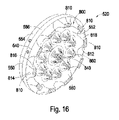
図10、11及び13に図示されているように、熱障壁520の熱抑制及び換気部540は、熱障壁の周囲に均等に分配された複数の空気入口/出口(換気口)800を含む。図示されている実施形態において、熱障壁は、中心から約36度で間隔をあけて配置されている10個の換気口を含む。換気口は、近位取付部530及び遠位取付部550を相互接続する、対応する複数の外側相互接続支柱810により形成される。各外側相互接続支柱は、近位取付部530の遠位面532から遠位取付部550の近位面552まで伸びている。 As illustrated in Figures 10, 11 and 13, the thermal suppression and ventilation portion 540 of the thermal barrier 520 includes a plurality of air inlet/outlets (vents) 800 evenly distributed around the periphery of the thermal barrier. In the illustrated embodiment, the thermal barrier includes ten vents spaced approximately 36 degrees from the center. The vent is formed by a corresponding plurality of outer interconnecting struts 810 interconnecting the proximal fitting 530 and the distal fitting 550 . Each outer interconnecting post extends from distal surface 532 of proximal mounting portion 530 to proximal surface 552 of distal mounting portion 550 .

図15及び16の断面斜視図に図示されているように、各外側相互接続支柱810は、2つの円周方向側部及び2つの半径方向側部により定義されるアーチ状の断面形状を有する。図15に図示されているように、各外側相互接続支柱は、近位取付部530の遠位面532の中心から約32mmの半径を有する円周に沿って配置されたアーチ状の内表面812を有する。各外側相互接続支柱は、近位取付部530の遠位面532の中心から約36mmの半径を有する円周に沿って配置されたアーチ状の外表面814を有する。アーチ状の外表面は、近位取付部530の外周面534から約5mm内側に配置されている。各外側相互接続支柱は、アーチ状の内表面812及びアーチ状の外表面814の間に約4mmの半径方向厚さを有する。アーチ状の内表面812及びアーチ状の外表面814は、外側相互接続支柱810の第1の半径方向面816及び第2の半径方向面818の間に約16度の角度を占めている。したがって、外側相互接続支柱の1つの第1の半径方向面は、隣接する外側相互接続支柱の第2の半径方向面から約20度の間隔をあけて配置されている。 15 and 16, each outer interconnecting strut 810 has an arcuate cross-sectional shape defined by two circumferential sides and two radial sides. 15, each outer interconnecting strut has an arcuate inner surface 812 disposed along a circumference having a radius of about 32 mm from the center of distal face 532 of proximal mounting portion 530. have Each outer interconnecting strut has an arcuate outer surface 814 circumferentially disposed with a radius of about 36 mm from the center of distal face 532 of proximal mounting portion 530 . The arcuate outer surface is positioned approximately 5 mm inward from the outer peripheral surface 534 of the proximal attachment portion 530 . Each outer interconnecting strut has a radial thickness of about 4 mm between the arcuate inner surface 812 and the arcuate outer surface 814 . Arcuate inner surface 812 and arcuate outer surface 814 occupy an angle of approximately 16 degrees between first radial surface 816 and second radial surface 818 of outer interconnecting strut 810 . Accordingly, the first radial surface of one of the outer interconnecting struts is spaced approximately 20 degrees from the second radial surface of the adjacent outer interconnecting strut.

さらに、図15に図示されているように、各外側相互接続支柱810のアーチ状の内表面812は、近位取付部530の遠位面532に対してフィレットを付けられる。図示されている実施形態において、各内表面フィレットは約1mmの半径を有する。第1の半径方向面816及び第2の半径方向面818のそれぞれも、近位取付部530の遠位面532に対してフィレットを付けられる。図示されている実施形態において、各半径方向面のフィレットは約1mmの半径を有する。図示されている実施形態において、各外側相互接続支柱810のアーチ状の外表面814は、近位取付部530の遠位面532に対してフィレットを付けられていない。 Further, as shown in FIG. 15, the arcuate inner surface 812 of each outer interconnecting strut 810 is filleted against the distal surface 532 of the proximal mounting portion 530 . In the illustrated embodiment, each inner surface fillet has a radius of about 1 mm. Each of first radial surface 816 and second radial surface 818 are also filleted to distal surface 532 of proximal mounting portion 530 . In the illustrated embodiment, each radial face fillet has a radius of about 1 mm. In the illustrated embodiment, the arcuate outer surface 814 of each outer interconnecting strut 810 is not filleted with respect to the distal surface 532 of the proximal mounting portion 530 .

各外側相互接続支柱810は、近位取付部530の遠位面532及び遠位取付部550の近位面552の両方に対して垂直に伸びている。したがって、図16の断面斜視図に図示されているように、各外側相互接続支柱810のアーチ状の内表面812はまた、遠位取付部550の近位面552の中心から約32mmの半径を有する円周に沿って配置されている。各外側相互接続支柱810のアーチ状の外表面814はまた、遠位取付部550の近位面552の中心から約36mmの半径を有する円周に沿って配置されている。遠位取付部550の第2の(近位)外周面556は近位取付部530の外周面534よりも小さな直径を有するので、アーチ状の外表面は近位取付部530の外周面534から約4mm内側に配置されている。 Each outer interconnecting strut 810 extends perpendicular to both the distal surface 532 of proximal mounting portion 530 and the proximal surface 552 of distal mounting portion 550 . 16, the arcuate inner surface 812 of each outer interconnecting strut 810 also extends approximately 32 mm from the center of the proximal surface 552 of the distal mounting portion 550. are arranged along the circumference of the The arcuate outer surface 814 of each outer interconnecting strut 810 is also arranged along a circumference having a radius of about 36 mm from the center of the proximal face 552 of the distal mounting portion 550 . Second (proximal) outer surface 556 of distal mounting portion 550 has a smaller diameter than outer surface 534 of proximal mounting portion 530 , so that the arcuate outer surface extends from outer surface 534 of proximal mounting portion 530 . It is located about 4 mm inside.

さらに、図16に図示されているように、各外側相互接続支柱810のアーチ状の内表面812及びアーチ状の外表面814は、遠位取付部550の近位面552に対してフィレットを付けられる。図示されている実施形態において、各内表面フィレットは約2mmの半径を有する。図示されている実施形態において、各外表面フィレットは約5mmの半径を有する。第1の半径方向面816及び第2の半径方向面818のそれぞれも、遠位取付部550の近位面552に対してフィレットを付けられる。図示されている実施形態において、各半径方向面のフィレットは約5mmの半径を有する。 Further, as shown in FIG. 16, the arcuate inner surface 812 and the arcuate outer surface 814 of each outer interconnecting strut 810 fillet against the proximal surface 552 of the distal mounting portion 550 . be done. In the illustrated embodiment, each inner surface fillet has a radius of about 2 mm. In the illustrated embodiment, each outer surface fillet has a radius of about 5 mm. Each of first radial surface 816 and second radial surface 818 are also filleted to proximal surface 552 of distal mounting portion 550 . In the illustrated embodiment, each radial face fillet has a radius of about 5 mm.

熱障壁520の中間熱抑制及び換気部540はさらに、中央相互接続支柱840を含む。図示されている実施形態において、中央相互接続支柱840は、中央貫通孔560と同心的に配置される。図15及び16の断面斜視図に図示されているように、中央相互接続支柱は、貫通孔から壁の厚さだけ間隔をあけて配置されている外表面542を有する。図示されている実施形態において、貫通孔は約5mmの直径を有し、外表面542は約10mmの直径を有する。したがって、壁の厚さは約2.5mmである。中央相互接続支柱の外表面は、図15に図示されているように、近位取付部530の遠位面532に対してフィレットを付けられ、図16に図示されているように、遠位取付部550の近位面552に対してもフィレットを付けられる。図示されている実施形態において、両方のフィレットは約5mmの共通の半径を有する。したがって、中央相互接続支柱の短い中間部の外表面のみが約10mmの外径を維持している。 Intermediate thermal suppression and ventilation portion 540 of thermal barrier 520 further includes a central interconnecting strut 840 . In the illustrated embodiment, central interconnecting post 840 is positioned concentrically with central through-hole 560 . As shown in the cross-sectional perspective views of FIGS. 15 and 16, the central interconnect strut has an outer surface 542 spaced from the through hole by the thickness of the wall. In the illustrated embodiment, the through holes have a diameter of approximately 5 mm and the outer surface 542 has a diameter of approximately 10 mm. The wall thickness is therefore about 2.5 mm. The outer surface of the central interconnecting strut is filleted against the distal surface 532 of the proximal attachment portion 530, as illustrated in FIG. 15, and the distal attachment, as illustrated in FIG. A proximal face 552 of portion 550 is also filleted. In the illustrated embodiment, both fillets have a common radius of approximately 5 mm. Thus, only the outer surface of the short intermediate portion of the central interconnect strut maintains an outer diameter of approximately 10 mm.

中央相互接続支柱840は、複数の内側相互接続支柱860により囲まれている。各内側相互接続支柱は、約5mmの基部直径を有し、近位取付部530の遠位面532から遠位取付部550の近位面552まで伸びている。各内側相互接続支柱の中心は、中央相互接続支柱の中心から約20mmの位置に配置されている。図示されている実施形態において、10個の内側相互接続支柱が、約36度で等角度に間隔をあけて配置されている。図15及び16に図示されているように、各内側相互接続支柱は、隣接する外側相互接続支柱810の間に実質的に等角度に配置された半径方向線に沿って配置されている。各内側相互接続支柱が換気口800のそれぞれ1つと実質的に半径方向に直線状に揃えられる。他の実施形態において、後部(電子機器部)512の片持ち荷重(cantilevered load)をさらに分配する為に、それぞれ小さな直径を有する追加の内側相互接続支柱を使用することもできる。 A central interconnecting strut 840 is surrounded by a plurality of inner interconnecting struts 860 . Each inner interconnecting strut has a base diameter of approximately 5 mm and extends from the distal surface 532 of the proximal mounting portion 530 to the proximal surface 552 of the distal mounting portion 550 . The center of each inner interconnecting strut is positioned approximately 20 mm from the center of the central interconnecting strut. In the illustrated embodiment, ten inner interconnecting struts are equiangularly spaced at approximately 36 degrees. As shown in FIGS. 15 and 16, each inner interconnection strut is arranged along a radial line that is substantially equiangularly spaced between adjacent outer interconnection struts 810 . Each inner interconnecting strut is substantially radially aligned with a respective one of the vents 800 . In other embodiments, additional inner interconnecting struts, each having a smaller diameter, can be used to further distribute the cantilevered load of the rear (electronics section) 512 .

図示されている実施形態において、内側相互接続支柱860のそれぞれは、近位取付部530の遠位面532及び遠位取付部550の近位面552に対してフィレットを付けられる。図示されている実施形態において、各フィレットは約5mmの半径を有する。 In the illustrated embodiment, each of the inner interconnecting struts 860 is filleted against the distal surface 532 of the proximal mounting portion 530 and the proximal surface 552 of the distal mounting portion 550 . In the illustrated embodiment, each fillet has a radius of approximately 5 mm.

図12、14、15及び16の断面図において、熱障壁520は硬質のポリエーテルエーテルケトン材料として図示されているが、熱障壁は、例えばハチの巣状等の、インフィル材料パターンに好ましくは構成される。ハチの巣状フィルパターンは、熱障壁全体の重量を減少し、材料費を減少し、前部510から後部512への熱障壁を通した熱伝達を減少する為に選択される。例えば、1つの実施形態において、ハチの巣状フィルパターンは、約20%の充填量を有するように選択される。図示されている実施形態において、ハチの巣状フィルパターンは、付加製造(例えば、3Dプリント)により達成される。選択された充填量は、後部の片持ち荷重を支持する構造強度及び熱伝達減少の間のトレードオフである。 Although the thermal barrier 520 is illustrated as a rigid polyetheretherketone material in the cross-sectional views of FIGS. 12, 14, 15 and 16, the thermal barrier is preferably configured in an infill material pattern, such as a honeycomb pattern. be done. The honeycomb fill pattern is selected to reduce the overall weight of the thermal barrier, reduce material costs, and reduce heat transfer through the thermal barrier from front section 510 to rear section 512 . For example, in one embodiment, the honeycomb fill pattern is selected to have a fill level of about 20%. In the illustrated embodiment, the honeycomb fill pattern is achieved by additive manufacturing (eg, 3D printing). The fill level selected is a trade-off between structural strength to support the rear cantilever load and heat transfer reduction.

上述のように、熱障壁520は、改良された圧力測定ユニット500の前部(センサ部)510及び後部(電子機器部)512の間の機械的相互接続構造として機能する。測定する圧力を有する(不図示の)システムに接続されると、改良された圧力測定ユニットは、システムの接合ネジ付き継手上にねじ込まれる圧力ポート120により支持される。前部、熱障壁及び後部の複合体が接合継手により支持される。入口管212水平方向に配向されるように改良された圧力測定ユニットが取り付けられると、複合体は接合継手上に力のモーメントを加える。改良された圧力測定ユニット500の後部512により加えられたモーメントは、前部及び後部の間に配置された熱障壁の追加された長さにより、慣習的な圧力検出ユニット100の後部202の対応するモーメントよりも大きい。近位面522及び遠位面532の間の熱障壁の厚さを実用的な限り小さくすることは、接合継手に対する後部のモーメントを減少する。 As described above, thermal barrier 520 serves as a mechanical interconnect structure between front (sensor portion) 510 and rear (electronics portion) 512 of improved pressure measurement unit 500 . When connected to a system (not shown) having the pressure to be measured, the modified pressure measurement unit is supported by a pressure port 120 that screws onto the mating threaded joint of the system. The front, thermal barrier and rear composites are supported by bonded joints. When the modified pressure measurement unit is mounted such that the inlet pipe 212 is horizontally oriented, the composite exerts a moment of force on the mating joint. The moment exerted by the rear portion 512 of the modified pressure measurement unit 500 corresponds to that of the rear portion 202 of the conventional pressure sensing unit 100 due to the added length of the thermal barrier placed between the front and rear portions. greater than the moment. Reducing the thickness of the thermal barrier between proximal face 522 and distal face 532 as small as practical reduces the rear moment on the bond joint.

前部510から後部512に熱障壁520を介して伝わる熱エネルギーの量は、障壁材料の熱伝導性に部分的に依存する。例えば、ポリエーテルエーテルケトンは、約0.25W/m・Kの熱伝導性を有する。ポリスルフォン(PSU)は、約0.26W/m・Kの熱伝導性を有する。ポリエーテルイミドは、約0.22W/m・K及び約0.12W/m・Kの間の熱伝導性を有する。 The amount of thermal energy transferred from front portion 510 to rear portion 512 through thermal barrier 520 depends in part on the thermal conductivity of the barrier material. For example, polyetheretherketone has a thermal conductivity of about 0.25 W/m·K. Polysulfone (PSU) has a thermal conductivity of about 0.26 W/m·K. Polyetherimide has a thermal conductivity between about 0.22 W/m·K and about 0.12 W/m·K.

前部510から後部512に熱障壁520を介して伝わる熱エネルギーの量は、熱経路長さを決定する前後部間の熱障壁の厚さに部分的に依存する。増加された厚さは、熱エネルギーの伝達を減少するが、増加した厚さは、上述のように、後部のモーメントも増加する。したがって、熱障壁の厚さを増加することは、後部のモーメントの許容可能な大きさにより限定される。熱障壁の厚さは、圧力ポート120から後面プレート114までの圧力測定ユニット500の全長によっても限定される。図示されている実施形態においては、11mmの厚さが、後部により加えられるモーメントを過度に増加することのない、前後部間の許容可能な距離を提供する。 The amount of thermal energy transferred from the front portion 510 to the rear portion 512 through the thermal barrier 520 depends in part on the thickness of the thermal barrier between the front and rear portions which determines the thermal path length. The increased thickness reduces the transfer of thermal energy, but the increased thickness also increases the rearward moment, as described above. Therefore, increasing the thickness of the thermal barrier is limited by the allowable magnitude of rear moment. The thermal barrier thickness is also limited by the overall length of pressure measurement unit 500 from pressure port 120 to backplate 114 . In the illustrated embodiment, a thickness of 11 mm provides an acceptable distance between the front and rear without unduly increasing the moment applied by the rear.

前部510から後部512に熱障壁520を介して伝わる熱エネルギーの量は、熱エネルギーが伝わる材料の面積に部分的に依存する。上述のように、熱障壁は、前部に取り付けられるように構成された近位取付部530を有し、そして、後部に取り付けられるように構成された遠位取付部550を有する。図示されている実施形態において、熱障壁520の近位取付部530は、約81mmの外径を有する。熱障壁520の遠位取付部550は、約75mmの最小外径を有する。したがって、熱障壁520の遠位取付部550の第2の表面524は、約4415mmの断面積を有する。熱障壁が近位取付部及び遠位取付部間に継続する中実材料であった場合、熱障壁は、不必要な大量の熱エネルギーを前部から後部へ伝達する。 The amount of thermal energy transferred from the front portion 510 to the rear portion 512 through the thermal barrier 520 depends in part on the area of the material through which the thermal energy is transferred. As described above, the thermal barrier has a proximal attachment portion 530 configured to be attached to the front and a distal attachment portion 550 configured to be attached to the rear. In the illustrated embodiment, the proximal mounting portion 530 of the thermal barrier 520 has an outer diameter of approximately 81 mm. Distal mounting portion 550 of thermal barrier 520 has a minimum outer diameter of approximately 75 mm. Accordingly, second surface 524 of distal mounting portion 550 of thermal barrier 520 has a cross-sectional area of approximately 4415 mm 2 . If the thermal barrier were a continuous solid material between the proximal and distal attachments, the thermal barrier would transfer an unnecessarily large amount of thermal energy from front to back.

熱障壁520の中間熱抑制及び換気部540を、複数の外側相互接続支柱810,中央相互接続支柱840、及び複数の内側相互接続支柱860を含む部分的に開放されている構造に構成することにより、中間熱抑制及び換気部の効果的な面積を近位及び遠位取付部の面積に対してかなり減少する。例えば、各々の相互接続支柱のフィレットが計算を簡略化する為に無視した場合、10個の外側相互接続支柱810のそれぞれは約37mmの断面積を有し、中央相互接続支柱840は約61mmの断面積を有し、10個の内側相互接続支柱860のそれぞれは約20mmの断面積を有する。したがって、支柱の総断面積は約631mmであり、熱障壁の第2の表面の断面積の約14.3%である。熱障壁のポリエーテルエーテルケトン材料を通して伝達されるエネルギーは、断面積に直接比例する。したがって、中実材料の代わりに支柱を有する中間熱抑制及び換気部を構成することにより、熱伝達は約85%減少される。 By configuring the intermediate thermal suppression and ventilation section 540 of the thermal barrier 520 into a partially open structure that includes a plurality of outer interconnecting struts 810, a central interconnecting strut 840, and a plurality of inner interconnecting struts 860. , the effective area of the intermediate heat suppression and ventilation section is significantly reduced relative to the area of the proximal and distal attachment sections. For example, each of the ten outer interconnecting struts 810 has a cross-sectional area of about 37 mm 2 and the central interconnecting strut 840 has a cross-sectional area of about 61 mm, if the fillet of each interconnecting strut is ignored to simplify the calculations. 2 , and each of the ten inner interconnecting struts 860 has a cross-sectional area of approximately 20 mm 2 . The total cross-sectional area of the struts is thus approximately 631 mm 2 , which is approximately 14.3% of the cross-sectional area of the second surface of the thermal barrier. The energy transferred through the polyetheretherketone material of the thermal barrier is directly proportional to the cross-sectional area. Thus, by constructing the intermediate heat restraint and vent with struts instead of solid material, heat transfer is reduced by approximately 85%.

支柱810、840、860にフィレットを追加することは効果的な断面積を追加することになるが、増加される断面積は中実のポリエーテルエーテルケトン材料の断面積よりは実質的に小さい断面積に維持される。フィレットを有する支柱の効果的な断面積は容易には計算できないが、フィレットを有する支柱の総容積は約6792mmであると計算することができる。したがって、フィレットを有する支柱の容積は、フィレットのない支柱の容積の約2.75倍である。比較すると、中実の中間熱抑制及び換気部の容積は約47105mmである。したがって、フィレットのない支柱の容積は、中実の中間熱抑制及び換気部の容積の約14.4%である。対照的に、フィレットを有する支柱の容積は、中実の中間熱抑制及び換気部の容積の約40%である。支柱総容積が中実の中間熱抑制及び換気部の容積の30%~50%であれば、後部512への熱エネルギー伝達に十分な障壁を提供することができ、また、後部への十分な構造支持を提供することができる。一般的に、支柱総容積は、中間熱抑制及び換気部の容積の約15%~50%の範囲であることができる。 Adding fillets to the struts 810, 840, 860 adds effective cross-sectional area, but the increased cross-sectional area is substantially less than that of the solid polyetheretherketone material. maintained in area. The effective cross-sectional area of the strut with fillets cannot be easily calculated, but the total volume of the strut with fillets can be calculated to be approximately 6792 mm 3 . Therefore, the volume of the struts with fillets is approximately 2.75 times the volume of struts without fillets. By comparison, the volume of the solid intermediate heat suppression and ventilation section is approximately 47105 mm 3 . Therefore, the fillet-free strut volume is about 14.4% of the volume of the solid intermediate heat suppression and ventilation section. In contrast, the volume of struts with fillets is approximately 40% of the volume of solid intermediate heat suppression and ventilation. A total strut volume of 30% to 50% of the volume of the solid intermediate heat suppression and ventilation section can provide a sufficient barrier to thermal energy transfer to the rear 512 and also provide sufficient barrier to the rear. Structural support can be provided. Generally, the total strut volume can range from about 15% to 50% of the volume of the intermediate heat suppression and ventilation section.

熱障壁520全体をハチの巣状又は他の減少された容積のインフィルを使用して構成することにより、熱伝達はさらに減少される。例えば、容積の約20%のハチの巣状インフィルにより、中実の材料に比べて熱伝達は約80%減少する。したがって、中間熱抑制及び換気部540の支柱構造及び熱障壁全体のハチの巣状フィルの組み合わせは、改良された圧力検出ユニット500の前部510から後部512への熱伝達に大幅な減少を提供する。さらに、上述のように、前部及び後部間の強固な機械的相互接続を維持したまま、減少された熱伝達が提供される。 Heat transfer is further reduced by constructing the entire thermal barrier 520 using honeycomb or other reduced volume infill. For example, a honeycomb infill of about 20% volume reduces heat transfer by about 80% compared to a solid material. Thus, the combination of the strut structure of the intermediate heat suppression and ventilation section 540 and the honeycomb fill across the thermal barrier provides a significant reduction in heat transfer from the front 510 to the rear 512 of the improved pressure sensing unit 500. do. Additionally, as described above, reduced heat transfer is provided while maintaining a strong mechanical interconnection between the front and rear portions.

上述の伝導熱伝達の減少は、中間熱抑制及び換気部540の部分的に開放されている構成により、さらに減少される。換気口800は、周囲空気が、一対の隣接する外側相互接続支柱810の間から、中間熱抑制及び換気部内に流入することを可能にする。移動する空気は外側相互接続支柱から熱を吸収する。移動する空気は、中間熱抑制及び換気部を通り、複数の内側相互接続支柱860及び中央相互接続支柱840を通過して支柱から熱を吸収する。加熱された空気は、他の換気口を介して、中間熱抑制及び換気部から出ていく。空気流による熱の除去は、熱障壁の近位取付部530から遠位取付部550への熱伝達をさらに減少する。 The reduction in conductive heat transfer described above is further reduced by the partially open configuration of intermediate heat suppression and ventilation section 540 . Vents 800 allow ambient air to enter between a pair of adjacent outer interconnecting struts 810 and into the intermediate heat suppression and ventilation section. Moving air absorbs heat from the outer interconnecting struts. Moving air passes through the intermediate heat suppression and ventilation section and passes through a plurality of inner interconnecting struts 860 and central interconnecting struts 840 to absorb heat from the struts. Heated air exits the intermediate heat suppression and ventilation section through other vents. Heat removal by air flow further reduces heat transfer from the proximal mounting portion 530 to the distal mounting portion 550 of the thermal barrier.

図示されている実施形態において、熱障壁520は、熱障壁520の近位面522の温度が約130℃である場合でも、熱障壁520の遠位面524の温度を約50℃以下に維持する為に効果的である。これらの条件において、高温炉筐体610内の隔膜真空計ハウジング224の温度は、250℃~300℃の高温である。 In the illustrated embodiment, the thermal barrier 520 maintains the temperature of the distal surface 524 of the thermal barrier 520 below about 50°C even when the temperature of the proximal surface 522 of the thermal barrier 520 is about 130°C. effective for Under these conditions, the temperature of diaphragm gauge housing 224 within high temperature furnace housing 610 is as high as 250.degree. C. to 300.degree.

本開示の発明の熱障壁は、静電容量型隔膜真空計及び以下の工程で第2の温度で動作する電子機器筐体の間に提供される。静電容量型隔膜真空計に機械的に係合するように構成された寸法及び形状を有する第1の取付境界面が提供される。電子機器筐体に係合するように構成された寸法及び形状を有する第2の取付境界面が提供される。第2の取付境界面は、第1の取付境界面から間隔をあけて配置されている。第1の取付境界面及び第2の取付境界面は、複数の支柱により相互接続されている。各支柱は、第1の取付境界面に機械的及び熱的に接続された第1の端部を有する。各支柱は、第2の取付境界面に機械的及び熱的に接続された第2の端部を有する。 The thermal barrier of the presently disclosed invention is provided between a capacitive diaphragm gauge and an electronics enclosure operating at a second temperature in the following steps. A first mounting interface is provided having a size and shape configured to mechanically engage a capacitive diaphragm gauge. A second mounting interface is provided having a size and shape configured to engage the electronics enclosure. The second mounting interface is spaced from the first mounting interface. The first mounting interface and the second mounting interface are interconnected by a plurality of struts. Each post has a first end mechanically and thermally connected to the first mounting interface. Each post has a second end mechanically and thermally connected to the second mounting interface.

図17、18、19A及び19Bを参照すると、熱障壁の他の実施形態が図示されている。この実施形態の熱障壁構造は、熱障壁筐体の発泡体として形成され、熱可塑性の熱障壁が筐体と1つの部品として均質化されている。図17は、熱障壁筐体の実施形態の斜視図であり、図18は、図17の線17-17に沿った熱障壁筐体の実施形態の断面図である。圧力測定ユニット900は、熱障壁筐体910及び後部円筒形外部カバー920を含む。後部円筒形外部カバー920は、静電容量型隔膜真空計210から信号を受信して圧力ポート120に接続された外部供給源の圧力を測定する上述の電子機器を収容する。図示されている実施形態において、後部は、上述の後部202及び502と同じ又は実質的に同じ要素を含むが、後部202及び502とは異なる特徴を有し、後部の対応する要素の番号は、本開示の発明の実施形態の圧力測定ユニット900に持ち越されている。熱障壁筐体910は、静電容量型隔膜真空計210及び他の関連要素を収容する。熱障壁筐体910は、静電容量型隔膜真空計210及び他の関連要素を囲む円筒形側壁911、円筒形側壁911により定義される筐体の底を形成する第1の壁912、及び第1の壁912から間隔をあけて配置された第2の壁913を含む。熱障壁筐体910はさらに、第1の壁912及び第2の壁913を相互接続する中間熱抑制及び換気部914を含む。中間熱抑制及び換気部914は、複数の支柱915(主支柱又は第1の支柱)を含む。 
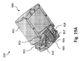
17, 18, 19A and 19B, another embodiment of a thermal barrier is illustrated. The thermal barrier structure of this embodiment is formed as a thermal barrier housing foam, where the thermoplastic thermal barrier is homogenized with the housing as one piece. 17 is a perspective view of an embodiment of a thermal barrier housing, and FIG. 18 is a cross-sectional view of an embodiment of a thermal barrier housing taken along line 17-17 in FIG. Pressure measurement unit 900 includes a thermal barrier housing 910 and a rear cylindrical outer cover 920 . A rear cylindrical outer cover 920 houses the electronics described above for receiving signals from the capacitive diaphragm gauge 210 to measure the pressure of an external source connected to the pressure port 120 . In the illustrated embodiment, the posterior portion includes the same or substantially the same elements as posterior portions 202 and 502 described above, but has different features than posterior portions 202 and 502, and corresponding element numbers for the posterior portion are: It carries over to the pressure measurement unit 900 of the inventive embodiment of the present disclosure. A thermal barrier enclosure 910 houses the capacitive diaphragm gauge 210 and other related components. A thermal barrier enclosure 910 includes a cylindrical sidewall 911 that encloses the capacitive diaphragm gauge 210 and other related elements, a first wall 912 that forms the bottom of the enclosure defined by the cylindrical sidewall 911, and a first wall 912 that forms the bottom of the enclosure defined by the cylindrical sidewall 911. It includes a second wall 913 spaced from the first wall 912 . Thermal barrier enclosure 910 further includes an intermediate heat suppression and ventilation section 914 interconnecting first wall 912 and second wall 913 . Intermediate heat suppression and ventilation section 914 includes a plurality of struts 915 (main struts or primary struts).

図19A及び19Bを参照すると、熱障壁筐体910の上部及び下部の斜視図が図示されている。図19Aは、熱障壁筐体910の上部930を示し、図19Bは、熱障壁筐体910の下部931を示す。上部930及び下部931は、互いに組み合わされて熱障壁筐体910を形成する。熱障壁筐体は、「クラムシェル」組み立て法を使用し、均質化された熱可塑性センサハウジング/電子機器熱障壁が中心軸に沿って切断されて2つの部分を形成し、その後、2つの部分を互いにねじ付けしてセンサを覆っている。このことは、センサは組み立て技術者に露出したまま、全てのヒータ、抵抗温度検出器(RTD)、及びセンサの導線が熱障壁筐体を通って外に出ることができるので、組み立ての助けになる。熱障壁筐体910は、中央貫通孔560が形成された中央相互接続支柱916、及び第2の貫通孔918が形成された1以上の第2の相互接続支柱917(第2の支柱)を含むことができる。第1の壁912及び第2の壁913は、中央相互接続支柱916及び第2の相互接続支柱917により接続される。中央貫通孔560及び第2の貫通孔918は、第1及び第2の壁を通って形成される。実施形態において、同軸の導体226は、中央貫通孔560を通って、静電容量型隔膜真空計210から外部カバー920により囲まれた電子機器まで伸びており、ヒータ、抵抗温度検出器、及びセンサの導線は、第2の支柱917内に形成された第2の貫通孔を通って、静電容量型隔膜真空計210から電子機器まで伸びている。このことは、外部カバー920により囲まれた電子機器内に配置されたアナログプリント回路基板又はデジタル信号処理プリント回路基板のいずれかに容易に接合する位置まで導線を外に出す為になされる。他の実施形態において、同軸の導体226及びヒータ、抵抗温度検出器、及びセンサの導線は、電子機器内の要素の配置により、中央貫通孔560又は他の第2の貫通孔918を通って伸びている。図19A及び19Bに図示されているように、中央貫通孔560及び第2の貫通孔918は、熱障壁筐体の上部又は下部に形成されることができ、又は、代替的に、中央貫通孔及び第2の貫通孔は、熱障壁筐体の上部及び下部の両方に形成されることができる。 19A and 19B, top and bottom perspective views of thermal barrier housing 910 are illustrated. 19A shows the top portion 930 of the thermal barrier enclosure 910 and FIG. 19B shows the bottom portion 931 of the thermal barrier enclosure 910. FIG. Top 930 and bottom 931 combine together to form thermal barrier housing 910 . The thermal barrier housing uses a "clamshell" assembly method in which the homogenized thermoplastic sensor housing/electronics thermal barrier is cut along the central axis to form two parts, which are then separated into two parts. are screwed together to cover the sensor. This aids in assembly as all heater, resistance temperature detector (RTD), and sensor leads can exit through the thermal barrier housing while the sensor remains exposed to the assembly engineer. Become. The thermal barrier housing 910 includes a central interconnecting post 916 with a central through hole 560 formed therein, and one or more second interconnecting posts 917 (second posts) with a second through hole 918 formed therein. be able to. First wall 912 and second wall 913 are connected by a central interconnecting strut 916 and a second interconnecting strut 917 . A central through hole 560 and a second through hole 918 are formed through the first and second walls. In an embodiment, the coaxial conductor 226 extends through the central through hole 560 from the capacitive diaphragm gauge 210 to the electronics enclosed by the outer cover 920 for heaters, resistance temperature detectors, and sensors. , extends from the capacitive diaphragm gauge 210 to the electronics through a second through hole formed in the second post 917 . This is done to bring the wires out to a position where they can be easily bonded to either an analog printed circuit board or a digital signal processing printed circuit board located within the electronics enclosed by the outer cover 920 . In other embodiments, the coaxial conductors 226 and wires of heaters, resistance temperature detectors, and sensors may extend through the central through-hole 560 or other secondary through-holes 918, depending on the placement of the components within the electronics. ing. As shown in FIGS. 19A and 19B, the central through-hole 560 and the second through-hole 918 can be formed in the top or bottom of the thermal barrier housing, or alternatively, the central through-hole and second through-holes can be formed in both the top and bottom of the thermal barrier housing.

図20A及び20Bを参照すると、図17の線18-18に沿った熱障壁筐体の断面図が図示されている。支柱915は第1の壁912に配置されている。実施形態において、各支柱は、中央貫通孔560を中心とする第1の円940に沿って配置される(図20A)。他の実施形態において、支柱は、中央貫通孔560から伸びている各支柱半径方向線941に沿って配置される(図20B)。しかしながら、支柱の配置は、これらの構成に限定されず、静電容量型隔膜真空計からの熱伝達を効果的に減少する為に異なる構成に配置することもできる。支柱915は、第1の壁912及び第2の壁913の両方に接続される。しかしながら、支柱は、第1の壁912及び第2の壁913の一方に接続されてもよい。例えば、支柱915は、第1の壁912に形成されて第2の壁913に向かって伸びているが、支柱915及び第2の壁913の間に隙間を形成することにより、支柱915は第2の壁913に接続されなくてもよい。図20A及び20Bには、第2の支柱917及び第2の支柱内に形成された第2の貫通孔918も図示されている。説明の目的から、図20A及び20Bには、垂直線に沿って配置された3つの第2の支柱が図示されているが、第2の支柱の数は3つに限定されない。垂直線は、上部930及び下部931が互いに接合されて熱障壁筐体の完全体を形成する部分(又は領域)を示している。さらに、第2の支柱は、電子機器内の要素の配置により異なる位置に配置されてもよい。 20A and 20B, a cross-sectional view of the thermal barrier housing along line 18-18 of FIG. 17 is illustrated. A post 915 is located on the first wall 912 . In an embodiment, each strut is arranged along a first circle 940 centered on central through hole 560 (FIG. 20A). In other embodiments, the struts are arranged along each strut radial line 941 extending from the central through hole 560 (FIG. 20B). However, the arrangement of the struts is not limited to these configurations and can be arranged in different configurations to effectively reduce heat transfer from the capacitive diaphragm gauge. A post 915 is connected to both the first wall 912 and the second wall 913 . However, the struts may be connected to one of the first wall 912 and the second wall 913 . For example, the post 915 is formed in the first wall 912 and extends toward the second wall 913, but by forming a gap between the post 915 and the second wall 913, the post 915 is in the second wall. It does not have to be connected to the second wall 913 . Figures 20A and 20B also show a second strut 917 and a second through hole 918 formed in the second strut. For purposes of illustration, FIGS. 20A and 20B show three second struts arranged along a vertical line, but the number of second struts is not limited to three. The vertical lines indicate the portion (or area) where top 930 and bottom 931 are joined together to form the complete thermal barrier enclosure. Additionally, the second post may be positioned at different locations depending on the placement of elements within the electronic device.

上述のように、中間熱抑制及び換気部914は、対流冷却気流の為の十分な空間を含む。側壁、第1の壁、第2の壁、及び中間熱抑制及び換気部は、1つの部品として一体に形成され、支柱は、図15及び16に図示されている実施形態の支柱よりも細く形成される。その結果、熱障壁筐体910は、電子機器への伝導(及びより大きな空隙を介した対流)熱伝達をさらに減少する。支柱915の総断面積は、図15及び16に図示されている実施形態の支柱の総断面積の約50%である。中間熱抑制及び換気部914は、第1の壁及び第2の壁の間の総容積を有する。総容積は、支柱の容積、第1及び第2の壁の間の空間、及び他の要素を含む。複数の支柱915は、支柱総容積を有する。熱障壁筐体910の細い支柱915により、支柱総容積は、中間熱抑制及び換気部914の総容積の約15%~約25%の範囲であり、電子機器への熱伝達を効果的に減少する。 As mentioned above, the intermediate heat suppression and ventilation section 914 includes sufficient space for convective cooling airflow. The side walls, first wall, second wall, and intermediate heat suppression and ventilation section are integrally formed as one piece, and the struts are formed narrower than the struts of the embodiment shown in FIGS. be done. As a result, the thermal barrier enclosure 910 further reduces conductive (and convective through larger air gaps) heat transfer to the electronics. The total cross-sectional area of struts 915 is approximately 50% of the total cross-sectional area of the struts of the embodiment illustrated in FIGS. Intermediate heat suppression and ventilation section 914 has a total volume between the first wall and the second wall. The total volume includes the column volume, the space between the first and second walls, and other factors. Plurality of struts 915 has a total strut volume. Due to the thin struts 915 of the thermal barrier housing 910, the total strut volume is in the range of about 15% to about 25% of the total volume of the intermediate heat suppression and ventilation section 914, effectively reducing heat transfer to the electronics. do.

発明の詳細な説明は、説明の目的で記載されている。したがって、新規で有用な発明の特定の実施形態が記載されているが、そのような参照は、特許請求の範囲に記載されている、本発明の範囲の限定を意図しているものではない。 The detailed description of the invention has been set forth for purposes of illustration. Accordingly, while specific embodiments of the invention that are new and useful have been described, such references are not intended to limit the scope of the invention, which is set forth in the claims.

100 圧力測定ユニット、圧力検出ユニット
110 円筒形の外殻
112 前面アンカープレート
114 後面プレート
120 圧力ポート、入口ポート
130 第1のコネクタ
132 第2のコネクタ
134 一対の取付ネジ
140 第1のLED
142 第2のLED
144 第3のLED
146 第1の埋込型押しボタンスイッチ
148 第2の埋込型押しボタンスイッチ
200 前部、圧力センサ部
202 後部、電子機器部
210 静電容量型隔膜真空計
212 入口管
214 断熱アダプタ
220 ダイアフラム
222 固定電極
224 隔膜真空計ハウジング、支持構造
226 同軸の導体
250 高温炉筐体、高温炉
252 第1の高温炉カバー
256 第2の高温炉カバー
260 中温炉筐体、中温炉
262 第1の中温炉カバー
264 第2の中温炉カバー
266 中央開口
300 入出力プリント回路基板
302 電力供給プリント回路基板
304 デジタル信号処理プリント回路基板
306 アナログプリント回路基板
310 プリント回路基板相互接続スタンドオフ
320 電子機器炉筐体
322 前後部相互接続スタンドオフ
330 プリント回路基板相互接続要素
500 圧力測定ユニット、圧力検出ユニット
510 前部、センサ部
512 後部、電子機器部
514 前部円筒形外部カバー
516 後部円筒形外部カバー
520 熱障壁
522 第1の表面、近位面
524 第2の表面、遠位面
530 近位取付部
532 530の遠位面
534 530の外周面
540 中間熱抑制及び換気部
550 遠位取付部
552 550の近位面
554 550の第1の外周面
556 550の第2の外周面
560 中央貫通孔
570 ネジ
572 ネジ
574 ネジ
600 入口管
610 高温炉筐体
612 610の遠位端
614 中央開口
616 610の近位端カバー
618 ネジ
630 円盤状アダプタ支持構造
640 断熱アダプタ
642 遠位基部
644 中間部
646 近位部
648 514の開口
650 アダプタネジ
652 アダプタネジ
700 円筒形断熱層
702 700の近位端
704 700の遠位端
710 第1の円盤状断熱層
712 中央開口
714 710の遠位面
716 710の近位面
720 第2の円盤状断熱層
730 第3の円盤状断熱層
740 第1の環状断熱層
750 第2の環状断熱層
770 ネジ
800 換気口
810 外側相互接続支柱
812 810のアーチ状の内表面
814 810のアーチ状の外表面
816 810の第1の半径方向面
818 810の第2の半径方向面
840 中央相互接続支柱
860 内側相互接続支柱
900 圧力測定ユニット
910 熱障壁筐体
911 円筒形側壁
912 第1の壁
913 第2の壁
914 中間熱抑制及び換気部
915 支柱
916 中央相互接続支柱
917 第2の相互接続支柱
918 第2の貫通孔
920 後部円筒形外部カバー
930 910の上部
931 910の下部
940 第1の円
941 支柱半径方向線
100 pressure measurement unit, pressure sensing unit 110 cylindrical shell 112 front anchor plate 114 rear plate 120 pressure port, inlet port 130 first connector 132 second connector 134 pair of mounting screws 140 first LED
142 second LED
144 third LED
146 first recessed pushbutton switch 148 second recessed pushbutton switch 200 front pressure sensor section 202 rear electronics section 210 capacitive diaphragm gauge 212 inlet tube 214 insulation adapter 220 diaphragm 222 Fixed Electrode 224 Diaphragm Gauge Housing, Support Structure 226 Coaxial Conductor 250 High Temperature Furnace Housing, High Temperature Furnace 252 First High Temperature Furnace Cover 256 Second High Temperature Furnace Cover 260 Medium Temperature Furnace, Medium Temperature Furnace 262 First Medium Temperature Furnace Cover 264 Second medium temperature furnace cover 266 Central opening 300 I/O printed circuit board 302 Power supply printed circuit board 304 Digital signal processing printed circuit board 306 Analog printed circuit board 310 Printed circuit board interconnect standoffs 320 Electronics furnace housing 322 Front and rear interconnection standoffs 330 Printed circuit board interconnection elements 500 Pressure measurement unit, pressure sensing unit 510 Front, sensor section 512 Rear, electronics section 514 Front cylindrical outer cover 516 Rear cylindrical outer cover 520 Thermal barrier 522 First surface, proximal surface 524 Second surface, distal surface 530 Distal surface 534 of proximal mounting portion 532 530 Peripheral surface 540 of 530 Intermediate heat suppression and ventilation portion 550 Proximal of distal mounting portion 552 550 First outer peripheral surface 556 550 Second outer surface 560 of surface 554 550 Central through hole 570 Screw 572 Screw 574 Screw 600 Inlet tube 610 Distal end 614 of high temperature furnace housing 612 610 Proximal end of central opening 616 610 cover 618 screw 630 disc shaped adapter support structure 640 insulating adapter 642 distal base 644 middle portion 646 proximal portion 648 514 opening 650 adapter screw 652 adapter screw 700 proximal end 704 700 of cylindrical insulating layer 702 700 710 First disc-shaped insulation layer 712 Central opening 714 Distal face 716 of 710 Proximal face 720 of 710 Second disc-shaped insulation layer 730 Third disc-shaped insulation layer 740 First annular insulation layer 750 Second Annular insulation layer 770 Screws 800 Vent 810 Arcuate inner surface 814 of outer interconnecting struts 812 810 First radial surface 818 of arcuate outer surface 816 810 Second radial surface 840 of 810 Central mutual connecting strut 860 inner interconnecting strut 900 pressure measuring unit 910 thermal barrier housing 911 cylindrical side wall 912 first wall 913 second second wall 914 intermediate heat suppression and ventilation section 915 strut 916 central interconnecting strut 917 second interconnecting strut 918 second through hole 920 rear cylindrical outer cover 930 top of 910 931 bottom of 910 940 first circle 941 strut radial line

Claims (20)

第1の温度で動作する静電容量型隔膜真空計(CDG)及び第2の温度で動作する電子機器筐体を相互接続する熱障壁筐体であって、前記第1の温度は前記第2の温度よりも高く、前記熱障壁筐体が、
前記静電容量型隔膜真空計を囲む側壁と、
前記静電容量型隔膜真空計と機械的に係合するように構成された第1の壁と、
前記第1の壁から間隔をあけて配置され、前記電子機器筐体と係合するように構成された第2の壁と、
前記第1の壁及び前記第2の壁に接続された中央相互接続支柱と、
前記中央相互接続支柱を囲む複数の支柱を含み、前記第1の壁及び前記第2の壁を相互接続する中間熱抑制及び換気部と、
を含み、
前記中央相互接続支柱は、前記静電容量型隔膜真空計から伸びている同軸の導体が内部に配置される中央貫通孔を定義し、
前記同軸の導体を介して、前記電子機器筐体内の電子機器及び前記静電容量型隔膜真空計の間で信号が送信されることを特徴とする熱障壁筐体。
A thermal barrier enclosure interconnecting a capacitive diaphragm gauge (CDG) operating at a first temperature and an electronics enclosure operating at a second temperature, wherein the first temperature is the second and the thermal barrier enclosure is
a side wall surrounding the capacitive diaphragm gauge;
a first wall configured to mechanically engage the capacitive diaphragm gauge;
a second wall spaced from the first wall and configured to engage the electronics housing;
a central interconnecting post connected to the first wall and the second wall;
an intermediate thermal suppression and ventilation section comprising a plurality of struts surrounding said central interconnecting strut and interconnecting said first wall and said second wall;
including
said central interconnecting post defines a central through hole in which a coaxial conductor extending from said capacitive diaphragm gauge is disposed;
A thermal barrier housing , wherein signals are transmitted between the electronics in the electronics housing and the capacitive diaphragm gauge via the coaxial conductor .
前記第1の壁は中央貫通孔を有し、前記複数の支柱のそれぞれは、前記中央貫通孔から伸びている各々の支柱半径方向線に沿って配置されることを特徴とする請求項1に記載の熱障壁筐体。 3. The method of claim 1, wherein said first wall has a central through-hole, and each of said plurality of struts is arranged along a respective post radial line extending from said central through-hole. A thermal barrier enclosure as described. 前記第1の壁は中央貫通孔を有し、前記複数の支柱のそれぞれは、前記中央貫通孔を中心とする第1の円に沿って配置されることを特徴とする請求項1に記載の熱障壁筐体。 2. The method of claim 1, wherein said first wall has a central through-hole, and wherein each of said plurality of struts are arranged along a first circle centered on said central through-hole. Thermal barrier enclosure. 前記複数の支柱は前記第1の壁及び前記第2の壁に接続されることを特徴とする請求項1に記載の熱障壁筐体。 2. The thermal barrier enclosure of claim 1, wherein said plurality of posts are connected to said first wall and said second wall. 前記中間熱抑制及び換気部は前記第1の壁及び前記第2の壁の間の総容積を有し、前記複数の支柱は支柱総容積を有し、前記支柱総容積は、前記総容積の約15%~約25%の範囲であることを特徴とする請求項1に記載の熱障壁筐体。 The intermediate heat suppression and ventilation section has a total volume between the first wall and the second wall, the plurality of struts has a total strut volume, and the total strut volume is less than the total volume. 2. The thermal barrier enclosure of claim 1, wherein the thermal barrier enclosure is in the range of about 15% to about 25%. 測定する圧力の供給源に接続可能であり、第1の温度で動作する静電容量型隔膜真空計(CDG)と、
前記静電容量型隔膜真空計に電気的に接続された電子機器を囲んでおり、前記第1の温度より低い第2の温度で動作する電子機器筐体と、
前記静電容量型隔膜真空計を収容し、前記静電容量型隔膜真空計及び前記電子機器筐体を相互接続する熱障壁筐体と、
を含む圧力検出システムであって、
前記熱障壁筐体が、
前記静電容量型隔膜真空計を囲む側壁と、
前記静電容量型隔膜真空計と機械的に係合するように構成された第1の壁と、
前記第1の壁から間隔をあけて配置され、前記電子機器筐体と係合するように構成された第2の壁と、
前記第1の壁及び前記第2の壁に接続された中央相互接続支柱と、
前記中央相互接続支柱を囲む複数の支柱を含み、前記第1の壁及び前記第2の壁を相互接続する中間熱抑制及び換気部と、
を含み、
前記中央相互接続支柱は、前記静電容量型隔膜真空計から伸びている同軸の導体が内部に配置される中央貫通孔を定義し、
前記同軸の導体を介して、前記電子機器筐体に囲まれた電子機器及び前記静電容量型隔膜真空計の間で信号が送信されることを特徴とする圧力検出システム。
a capacitance diaphragm gauge (CDG) connectable to a source of pressure to be measured and operating at a first temperature;
an electronics enclosure enclosing electronics electrically connected to the capacitive diaphragm gauge and operating at a second temperature lower than the first temperature;
a thermal barrier housing containing the capacitive diaphragm gauge and interconnecting the capacitive diaphragm gauge and the electronics housing;
A pressure sensing system comprising:
The thermal barrier enclosure is
a side wall surrounding the capacitive diaphragm gauge;
a first wall configured to mechanically engage the capacitive diaphragm gauge;
a second wall spaced from the first wall and configured to engage the electronics housing;
a central interconnecting post connected to the first wall and the second wall;
an intermediate thermal suppression and ventilation section comprising a plurality of struts surrounding said central interconnecting strut and interconnecting said first wall and said second wall;
including
said central interconnecting post defines a central through hole in which a coaxial conductor extending from said capacitive diaphragm gauge is disposed;
A pressure detection system , wherein signals are transmitted between the electronic device enclosed in the electronic device housing and the capacitive diaphragm vacuum gauge via the coaxial conductor .
前記第1の壁は中央貫通孔を有し、前記複数の支柱のそれぞれは、前記中央貫通孔から伸びている各々の支柱半径方向線に沿って配置されることを特徴とする請求項に記載の圧力検出システム。 7. The method of claim 6 , wherein said first wall has a central through-hole, and each of said plurality of struts are arranged along a respective radial line of post extending from said central through-hole. A pressure sensing system as described. 前記第1の壁は中央貫通孔を有し、前記複数の支柱のそれぞれは、前記中央貫通孔を中心とする第1の円に沿って配置されることを特徴とする請求項に記載の圧力検出システム。 7. The method of claim 6 , wherein said first wall has a central through-hole, and wherein each of said plurality of struts are arranged along a first circle centered on said central through-hole. Pressure sensing system. 前記複数の支柱は前記第1の壁及び前記第2の壁に接続されることを特徴とする請求項に記載の圧力検出システム。 7. The pressure sensing system of claim 6 , wherein said plurality of struts are connected to said first wall and said second wall. 前記中間熱抑制及び換気部は前記第1の壁及び前記第2の壁の間の総容積を有し、前記複数の支柱は支柱総容積を有し、前記支柱総容積は、前記総容積の約15%~約25%の範囲であることを特徴とする請求項に記載の圧力検出システム。 The intermediate heat suppression and ventilation section has a total volume between the first wall and the second wall, the plurality of struts has a total strut volume, and the total strut volume is less than the total volume. 7. The pressure sensing system of claim 6 , wherein the range is from about 15% to about 25%. さらに、前記静電容量型隔膜真空計を囲む炉筐体を含むことを特徴とする請求項に記載の圧力検出システム。 7. The pressure sensing system of claim 6 , further comprising a furnace housing surrounding said capacitive diaphragm gauge. さらに、前記熱障壁筐体の前記側壁と前記炉筐体の間の空間を埋める断熱層を含むことを特徴とする請求項11に記載の圧力検出システム。 12. The pressure sensing system of claim 11 , further comprising a thermal insulation layer filling a space between said sidewall of said thermal barrier enclosure and said furnace enclosure. 第1の温度で動作する静電容量型隔膜真空計(CDG)及び第2の温度で動作する電子機器筐体を相互接続する熱障壁であって、前記第1の温度は前記第2の温度よりも高く、前記熱障壁が、
前記静電容量型隔膜真空計と機械的に係合するように構成された第1の取付境界面と、
前記第1の取付境界面から間隔をあけて配置され、前記電子機器筐体と係合するように構成された第2の取付境界面と、
前記第1の取付境界面及び前記第2の取付境界面に接続された中央相互接続支柱と、
前記中央相互接続支柱を囲む複数の支柱を含み、前記第1の取付境界面及び前記第2の取付境界面を相互接続する中間熱抑制及び換気部と、
を含み、
前記中央相互接続支柱は、前記静電容量型隔膜真空計から伸びている同軸の導体が内部に配置される中央貫通孔を定義し、
前記同軸の導体を介して、前記電子機器筐体内の電子機器及び前記静電容量型隔膜真空計の間で信号が送信されることを特徴とする熱障壁。
A thermal barrier interconnecting a capacitive diaphragm gauge (CDG) operating at a first temperature and an electronics enclosure operating at a second temperature, wherein the first temperature is the second temperature and the thermal barrier is higher than
a first mounting interface configured to mechanically engage the capacitive diaphragm gauge;
a second mounting interface spaced from the first mounting interface and configured to engage the electronics enclosure;
a central interconnecting post connected to the first mounting interface and the second mounting interface;
an intermediate thermal suppression and ventilation section including a plurality of struts surrounding said central interconnecting strut and interconnecting said first mounting interface and said second mounting interface;
including
said central interconnecting post defines a central through hole in which a coaxial conductor extending from said capacitive diaphragm gauge is disposed;
A thermal barrier , wherein signals are transmitted between electronics in the electronics enclosure and the capacitive diaphragm gauge via the coaxial conductor .
前記中間熱抑制及び換気部は前記第1の取付境界面及び前記第2の取付境界面の間の総容積を有し、前記複数の支柱は支柱総容積を有し、前記支柱総容積は、前記総容積の約15%~約50%の範囲であることを特徴とする請求項13に記載の熱障壁。 The intermediate thermal suppression and ventilation section has a total volume between the first mounting interface and the second mounting interface, the plurality of struts has a total strut volume, and the total strut volume is: 14. The thermal barrier of claim 13 , ranging from about 15% to about 50% of said total volume. 前記支柱総容積は、前記総容積の約40%であることを特徴とする請求項14に記載の熱障壁。 15. The thermal barrier of Claim 14 , wherein the total strut volume is about 40% of the total volume. 前記複数の支柱が、
隣接する外側相互接続支柱の間に換気口を提供する為に間隔をあけて配置されている複数の外側相互接続支柱と、
空気流が前記中間熱抑制及び換気部を通ることを可能にする為に、前記換気口から間隔をあけて配置され、そして、互いに間隔をあけて配置された複数の内側相互接続支柱と、
を含むことを特徴とする請求項13に記載の熱障壁。
The plurality of struts are
a plurality of outer interconnecting struts spaced apart to provide ventilation between adjacent outer interconnecting struts;
a plurality of inner interconnecting struts spaced from said vent and spaced from each other for permitting airflow through said intermediate heat suppression and ventilation section;
14. The thermal barrier of claim 13 , comprising:
前記第1の取付境界面及び前記第2の取付境界面のそれぞれは、各々の中央貫通孔を有し、
前記複数の外側相互接続支柱のそれぞれは、前記中央貫通孔から伸びている各々の外側相互接続支柱半径方向線に沿って配置され、
前記複数の内側相互接続支柱のそれぞれは、前記中央貫通孔から伸びている各々の内側相互接続支柱半径方向線に沿って配置され、
前記各々の内側相互接続支柱半径方向線は、各々の第1の外側相互接続支柱半径方向線及び第2の外側相互接続支柱半径方向線の間に、実質的に等角度で配置されることを特徴とする請求項16に記載の熱障壁。
each of the first mounting interface and the second mounting interface having a respective central through hole;
each of the plurality of outer interconnecting struts are arranged along a respective outer interconnecting strut radial line extending from the central through hole;
each of the plurality of inner interconnecting struts disposed along a respective inner interconnecting strut radial line extending from the central through hole;
said each inner interconnecting strut radial line being disposed substantially equiangularly between each first outer interconnecting strut radial line and second outer interconnecting strut radial line; 17. A thermal barrier according to claim 16 .
前記第1の取付境界面及び前記第2の取付境界面のそれぞれは、各々の中央貫通孔を有し、
前記複数の外側相互接続支柱のそれぞれは、前記中央貫通孔を中心とする第1の円に沿って配置され、前記第1の円は第1の半径を有し、
前記複数の内側相互接続支柱のそれぞれは、前記中央貫通孔を中心とする第2の円に沿って配置され、前記第2の円は第2の半径を有し、前記第2の半径は前記第1の半径よりも小さいことを特徴とする請求項16に記載の熱障壁。
each of the first mounting interface and the second mounting interface having a respective central through hole;
each of the plurality of outer interconnecting struts is arranged along a first circle centered on the central through hole, the first circle having a first radius;
Each of said plurality of inner interconnecting struts is arranged along a second circle centered on said central through hole, said second circle having a second radius, said second radius being said 17. The thermal barrier of claim 16 , being less than the first radius.
さらに、前記中央相互接続支柱から間隔をあけて配置された1以上の第2の相互接続支柱を含み、前記1以上の第2の相互接続支柱は、1以上のヒータ、抵抗温度検出器(RTD)及びセンサの為に、前記静電容量型隔膜真空計から前記電子機器筐体内の電子機器まで伸びている導線が内部に配置される各々の第2の貫通孔を定義することを特徴とする請求項1に記載の熱障壁筐体。Further comprising one or more second interconnection posts spaced from said central interconnection post, said one or more second interconnection posts being connected to one or more heaters, resistance temperature detectors (RTDs) ) and sensors, defining respective second through-holes in which conductors extending from the capacitive diaphragm gauge to the electronics in the electronics enclosure are disposed. The thermal barrier enclosure of Claim 1. さらに、前記中央相互接続支柱から間隔をあけて配置された1以上の第2の相互接続支柱を含み、前記1以上の第2の相互接続支柱は、1以上のヒータ、抵抗温度検出器(RTD)及びセンサの為に、前記静電容量型隔膜真空計から前記電子機器筐体に囲まれた電子機器まで伸びている導線が内部に配置される各々の第2の貫通孔を定義することを特徴とする請求項6に記載の圧力検出システム。Further comprising one or more second interconnection posts spaced from said central interconnection post, said one or more second interconnection posts being connected to one or more heaters, resistance temperature detectors (RTDs) ) and sensors, each second through hole in which is disposed a wire extending from the capacitive diaphragm gauge to the electronics enclosed in the electronics housing. 7. The pressure sensing system of claim 6.
JP2021549950A 2019-02-26 2020-02-25 Thermal barrier between electronics and high temperature sensors in capacitive diaphragm gauges Active JP7140925B2 (en)

Applications Claiming Priority (3)

Application Number Priority Date Filing Date Title
US201962810798P 2019-02-26 2019-02-26
US62/810,798 2019-02-26
PCT/US2020/019688 WO2020176495A1 (en) 2019-02-26 2020-02-25 Thermal barrier between high-temperature sensor and electronics in a capacitance diaphragm gauge

Publications (2)

Publication Number Publication Date
JP2022522288A JP2022522288A (en) 2022-04-15
JP7140925B2 true JP7140925B2 (en) 2022-09-21

Family

ID=72239893

Family Applications (1)

Application Number Title Priority Date Filing Date
JP2021549950A Active JP7140925B2 (en) 2019-02-26 2020-02-25 Thermal barrier between electronics and high temperature sensors in capacitive diaphragm gauges

Country Status (7)

Country Link
US (1) US11768119B2 (en)
EP (1) EP3931541A4 (en)
JP (1) JP7140925B2 (en)
KR (1) KR102539918B1 (en)
CN (1) CN113260843B (en)
TW (1) TWI741510B (en)
WO (1) WO2020176495A1 (en)

Families Citing this family (2)

* Cited by examiner, † Cited by third party
Publication number Priority date Publication date Assignee Title
JP1685892S (en) * 2020-10-01 2021-05-24
WO2023101715A1 (en) * 2021-12-03 2023-06-08 Sumitomo (Shi) Cryogenics Of America, Inc. Thermal insulation system for a capacitance diaphragm gauge

Citations (5)

* Cited by examiner, † Cited by third party
Publication number Priority date Publication date Assignee Title
JP3100986B2 (en) 1996-01-16 2000-10-23 エムケイエス・インストゥルメンツ・インコーポレーテッド Improved heated pressure transducer assembly
JP3334888B2 (en) 1996-07-15 2002-10-15 エムケイエス・インストゥルメンツ・インコーポレーテッド Improved heated pressure transducer assembly
JP4437336B2 (en) 1999-05-14 2010-03-24 キヤノンアネルバ株式会社 Capacitive vacuum sensor
JP4988732B2 (en) 2005-07-13 2012-08-01 エム ケー エス インストルメンツ インコーポレーテッド Thermal mounting plate for heated pressure transducer
JP5576331B2 (en) 2011-03-31 2014-08-20 アズビル株式会社 Pressure sensor device

Family Cites Families (10)

* Cited by examiner, † Cited by third party
Publication number Priority date Publication date Assignee Title
JPS5719646A (en) 1980-07-09 1982-02-01 Olympus Optical Co Ltd Calibration method for electrolyte measurement in automatic biochemical analyzer with builtin type flame light photometer
JP4162990B2 (en) * 2000-08-11 2008-10-08 エム ケー エス インストルメンツ インコーポレーテッド Improved, capacitive-based pressure sensor design
US6612176B2 (en) * 2000-12-28 2003-09-02 Mks Instruments, Inc. Pressure transducer assembly with thermal shield
US7201057B2 (en) * 2004-09-30 2007-04-10 Mks Instruments, Inc. High-temperature reduced size manometer
JP5143736B2 (en) * 2005-08-12 2013-02-13 インフィコン ゲゼルシャフト ミット ベシュレンクテル ハフツング Measuring cell and manufacturing method thereof
WO2008154760A1 (en) * 2007-06-19 2008-12-24 Inficon Gmbh Vacuum measuring cell device having a heater
CN100595022C (en) * 2008-02-01 2010-03-24 黄崇贤 Method for producing column-shaped radiator
JP2014126503A (en) * 2012-12-27 2014-07-07 Azbil Corp Capacitance type pressure sensor
CN103929925A (en) * 2013-01-16 2014-07-16 欧司朗有限公司 Radiation device, electronic device comprising same and lighting device comprising same
CN203848247U (en) * 2014-04-30 2014-09-24 佛山市朗士照明有限公司 Cooler

Patent Citations (5)

* Cited by examiner, † Cited by third party
Publication number Priority date Publication date Assignee Title
JP3100986B2 (en) 1996-01-16 2000-10-23 エムケイエス・インストゥルメンツ・インコーポレーテッド Improved heated pressure transducer assembly
JP3334888B2 (en) 1996-07-15 2002-10-15 エムケイエス・インストゥルメンツ・インコーポレーテッド Improved heated pressure transducer assembly
JP4437336B2 (en) 1999-05-14 2010-03-24 キヤノンアネルバ株式会社 Capacitive vacuum sensor
JP4988732B2 (en) 2005-07-13 2012-08-01 エム ケー エス インストルメンツ インコーポレーテッド Thermal mounting plate for heated pressure transducer
JP5576331B2 (en) 2011-03-31 2014-08-20 アズビル株式会社 Pressure sensor device

Also Published As

Publication number Publication date
US11768119B2 (en) 2023-09-26
KR20210101328A (en) 2021-08-18
CN113260843B (en) 2023-09-12
TW202102826A (en) 2021-01-16
WO2020176495A1 (en) 2020-09-03
JP2022522288A (en) 2022-04-15
EP3931541A4 (en) 2022-11-23
TWI741510B (en) 2021-10-01
CN113260843A (en) 2021-08-13
KR102539918B1 (en) 2023-06-02
US20220090974A1 (en) 2022-03-24
EP3931541A1 (en) 2022-01-05

Similar Documents

Publication Publication Date Title
JP7140925B2 (en) Thermal barrier between electronics and high temperature sensors in capacitive diaphragm gauges
US6510740B1 (en) Thermal management in a pressure transmitter
RU2543690C2 (en) Electric plug-in connector for heat element and method of its manufacturing
US7824101B2 (en) Sensor arrangement
JP5947282B2 (en) Flow meter probe
JP4563312B2 (en) Capacitive pressure sensor device
JP2000515967A (en) Improved heated pressure transducer assembly
JP2006215029A (en) Combined pressure and temperature transducer
JP2019168450A (en) Assembly for detecting temperature and contact assembly having such assembly
TW202026633A (en) Liquid detection in a sensor environment and remedial action thereof
WO2019184467A1 (en) Temperature measuring device and microwave cooking appliance
TWI471538B (en) Temperature sensor for wafer cups
JP4600778B2 (en) Sensor that electrostatically measures the distance to the target
TWI709734B (en) Temperature detector probe with thermal isolation
JPH03504277A (en) pressure gauge
US20200003630A1 (en) Temperature measurement
SE461429B (en) CONNECTOR TO A MICROWAVE DEVICE
KR102565161B1 (en) Measuring sensor for calculating humidity
CN111397758A (en) Temperature detector
GB2559987A (en) Temperature measurement
JP3161803B2 (en) Differential scanning calorimeter
JP2554207Y2 (en) Semiconductor heat detector
EP3367078A1 (en) Temperature measurement
US20230175907A1 (en) Thermal Insulation System for a Capacitance Diaphragm Gauge
US11506544B2 (en) Monitoring the state of a temperature sensor

Legal Events

Date Code Title Description
A521 Request for written amendment filed

Free format text: JAPANESE INTERMEDIATE CODE: A523

Effective date: 20211026

A621 Written request for application examination

Free format text: JAPANESE INTERMEDIATE CODE: A621

Effective date: 20211026

TRDD Decision of grant or rejection written
A977 Report on retrieval

Free format text: JAPANESE INTERMEDIATE CODE: A971007

Effective date: 20220817

A01 Written decision to grant a patent or to grant a registration (utility model)

Free format text: JAPANESE INTERMEDIATE CODE: A01

Effective date: 20220823

A61 First payment of annual fees (during grant procedure)

Free format text: JAPANESE INTERMEDIATE CODE: A61

Effective date: 20220908

R150 Certificate of patent or registration of utility model

Ref document number: 7140925

Country of ref document: JP

Free format text: JAPANESE INTERMEDIATE CODE: R150