JP7140828B2 - Arithmetic device, detection system, molding device, arithmetic method, detection method, molding method, arithmetic program, detection program and molding program - Google Patents

Arithmetic device, detection system, molding device, arithmetic method, detection method, molding method, arithmetic program, detection program and molding program Download PDF

Info

Publication number
JP7140828B2
JP7140828B2 JP2020525016A JP2020525016A JP7140828B2 JP 7140828 B2 JP7140828 B2 JP 7140828B2 JP 2020525016 A JP2020525016 A JP 2020525016A JP 2020525016 A JP2020525016 A JP 2020525016A JP 7140828 B2 JP7140828 B2 JP 7140828B2
Authority
JP
Japan
Prior art keywords
powder material
modeling
unit
irradiation
state
Prior art date
Legal status (The legal status is an assumption and is not a legal conclusion. Google has not performed a legal analysis and makes no representation as to the accuracy of the status listed.)
Active
Application number
JP2020525016A
Other languages
Japanese (ja)
Other versions
JPWO2019239530A1 (en
Inventor
孝樹 竹下
Current Assignee (The listed assignees may be inaccurate. Google has not performed a legal analysis and makes no representation or warranty as to the accuracy of the list.)
Nikon Corp
Technology Research Association for Future Additive Manufacturing (TRAFAM)
Original Assignee
Nikon Corp
Technology Research Association for Future Additive Manufacturing (TRAFAM)
Priority date (The priority date is an assumption and is not a legal conclusion. Google has not performed a legal analysis and makes no representation as to the accuracy of the date listed.)
Filing date
Publication date
Application filed by Nikon Corp, Technology Research Association for Future Additive Manufacturing (TRAFAM) filed Critical Nikon Corp
Publication of JPWO2019239530A1 publication Critical patent/JPWO2019239530A1/en
Priority to JP2022143104A priority Critical patent/JP7427736B2/en
Application granted granted Critical
Publication of JP7140828B2 publication Critical patent/JP7140828B2/en
Priority to JP2024008901A priority patent/JP2024038476A/en
Active legal-status Critical Current
Anticipated expiration legal-status Critical

Links

Images

Classifications

    • BPERFORMING OPERATIONS; TRANSPORTING
    • B29WORKING OF PLASTICS; WORKING OF SUBSTANCES IN A PLASTIC STATE IN GENERAL
    • B29CSHAPING OR JOINING OF PLASTICS; SHAPING OF MATERIAL IN A PLASTIC STATE, NOT OTHERWISE PROVIDED FOR; AFTER-TREATMENT OF THE SHAPED PRODUCTS, e.g. REPAIRING
    • B29C64/00Additive manufacturing, i.e. manufacturing of three-dimensional [3D] objects by additive deposition, additive agglomeration or additive layering, e.g. by 3D printing, stereolithography or selective laser sintering
    • B29C64/30Auxiliary operations or equipment
    • B29C64/386Data acquisition or data processing for additive manufacturing
    • B29C64/393Data acquisition or data processing for additive manufacturing for controlling or regulating additive manufacturing processes
    • BPERFORMING OPERATIONS; TRANSPORTING
    • B22CASTING; POWDER METALLURGY
    • B22FWORKING METALLIC POWDER; MANUFACTURE OF ARTICLES FROM METALLIC POWDER; MAKING METALLIC POWDER; APPARATUS OR DEVICES SPECIALLY ADAPTED FOR METALLIC POWDER
    • B22F10/00Additive manufacturing of workpieces or articles from metallic powder
    • B22F10/30Process control
    • B22F10/32Process control of the atmosphere, e.g. composition or pressure in a building chamber
    • B22F10/322Process control of the atmosphere, e.g. composition or pressure in a building chamber of the gas flow, e.g. rate or direction
    • BPERFORMING OPERATIONS; TRANSPORTING
    • B22CASTING; POWDER METALLURGY
    • B22FWORKING METALLIC POWDER; MANUFACTURE OF ARTICLES FROM METALLIC POWDER; MAKING METALLIC POWDER; APPARATUS OR DEVICES SPECIALLY ADAPTED FOR METALLIC POWDER
    • B22F10/00Additive manufacturing of workpieces or articles from metallic powder
    • B22F10/30Process control
    • B22F10/34Process control of powder characteristics, e.g. density, oxidation or flowability
    • BPERFORMING OPERATIONS; TRANSPORTING
    • B22CASTING; POWDER METALLURGY
    • B22FWORKING METALLIC POWDER; MANUFACTURE OF ARTICLES FROM METALLIC POWDER; MAKING METALLIC POWDER; APPARATUS OR DEVICES SPECIALLY ADAPTED FOR METALLIC POWDER
    • B22F10/00Additive manufacturing of workpieces or articles from metallic powder
    • B22F10/30Process control
    • B22F10/36Process control of energy beam parameters
    • B22F10/364Process control of energy beam parameters for post-heating, e.g. remelting
    • BPERFORMING OPERATIONS; TRANSPORTING
    • B22CASTING; POWDER METALLURGY
    • B22FWORKING METALLIC POWDER; MANUFACTURE OF ARTICLES FROM METALLIC POWDER; MAKING METALLIC POWDER; APPARATUS OR DEVICES SPECIALLY ADAPTED FOR METALLIC POWDER
    • B22F10/00Additive manufacturing of workpieces or articles from metallic powder
    • B22F10/30Process control
    • B22F10/36Process control of energy beam parameters
    • B22F10/368Temperature or temperature gradient, e.g. temperature of the melt pool
    • BPERFORMING OPERATIONS; TRANSPORTING
    • B22CASTING; POWDER METALLURGY
    • B22FWORKING METALLIC POWDER; MANUFACTURE OF ARTICLES FROM METALLIC POWDER; MAKING METALLIC POWDER; APPARATUS OR DEVICES SPECIALLY ADAPTED FOR METALLIC POWDER
    • B22F10/00Additive manufacturing of workpieces or articles from metallic powder
    • B22F10/30Process control
    • B22F10/37Process control of powder bed aspects, e.g. density
    • BPERFORMING OPERATIONS; TRANSPORTING
    • B22CASTING; POWDER METALLURGY
    • B22FWORKING METALLIC POWDER; MANUFACTURE OF ARTICLES FROM METALLIC POWDER; MAKING METALLIC POWDER; APPARATUS OR DEVICES SPECIALLY ADAPTED FOR METALLIC POWDER
    • B22F10/00Additive manufacturing of workpieces or articles from metallic powder
    • B22F10/50Treatment of workpieces or articles during build-up, e.g. treatments applied to fused layers during build-up
    • BPERFORMING OPERATIONS; TRANSPORTING
    • B22CASTING; POWDER METALLURGY
    • B22FWORKING METALLIC POWDER; MANUFACTURE OF ARTICLES FROM METALLIC POWDER; MAKING METALLIC POWDER; APPARATUS OR DEVICES SPECIALLY ADAPTED FOR METALLIC POWDER
    • B22F10/00Additive manufacturing of workpieces or articles from metallic powder
    • B22F10/80Data acquisition or data processing
    • B22F10/85Data acquisition or data processing for controlling or regulating additive manufacturing processes
    • BPERFORMING OPERATIONS; TRANSPORTING
    • B22CASTING; POWDER METALLURGY
    • B22FWORKING METALLIC POWDER; MANUFACTURE OF ARTICLES FROM METALLIC POWDER; MAKING METALLIC POWDER; APPARATUS OR DEVICES SPECIALLY ADAPTED FOR METALLIC POWDER
    • B22F12/00Apparatus or devices specially adapted for additive manufacturing; Auxiliary means for additive manufacturing; Combinations of additive manufacturing apparatus or devices with other processing apparatus or devices
    • B22F12/40Radiation means
    • B22F12/41Radiation means characterised by the type, e.g. laser or electron beam
    • BPERFORMING OPERATIONS; TRANSPORTING
    • B22CASTING; POWDER METALLURGY
    • B22FWORKING METALLIC POWDER; MANUFACTURE OF ARTICLES FROM METALLIC POWDER; MAKING METALLIC POWDER; APPARATUS OR DEVICES SPECIALLY ADAPTED FOR METALLIC POWDER
    • B22F12/00Apparatus or devices specially adapted for additive manufacturing; Auxiliary means for additive manufacturing; Combinations of additive manufacturing apparatus or devices with other processing apparatus or devices
    • B22F12/40Radiation means
    • B22F12/49Scanners
    • BPERFORMING OPERATIONS; TRANSPORTING
    • B22CASTING; POWDER METALLURGY
    • B22FWORKING METALLIC POWDER; MANUFACTURE OF ARTICLES FROM METALLIC POWDER; MAKING METALLIC POWDER; APPARATUS OR DEVICES SPECIALLY ADAPTED FOR METALLIC POWDER
    • B22F12/00Apparatus or devices specially adapted for additive manufacturing; Auxiliary means for additive manufacturing; Combinations of additive manufacturing apparatus or devices with other processing apparatus or devices
    • B22F12/90Means for process control, e.g. cameras or sensors
    • BPERFORMING OPERATIONS; TRANSPORTING
    • B29WORKING OF PLASTICS; WORKING OF SUBSTANCES IN A PLASTIC STATE IN GENERAL
    • B29CSHAPING OR JOINING OF PLASTICS; SHAPING OF MATERIAL IN A PLASTIC STATE, NOT OTHERWISE PROVIDED FOR; AFTER-TREATMENT OF THE SHAPED PRODUCTS, e.g. REPAIRING
    • B29C64/00Additive manufacturing, i.e. manufacturing of three-dimensional [3D] objects by additive deposition, additive agglomeration or additive layering, e.g. by 3D printing, stereolithography or selective laser sintering
    • B29C64/10Processes of additive manufacturing
    • B29C64/141Processes of additive manufacturing using only solid materials
    • B29C64/153Processes of additive manufacturing using only solid materials using layers of powder being selectively joined, e.g. by selective laser sintering or melting
    • BPERFORMING OPERATIONS; TRANSPORTING
    • B33ADDITIVE MANUFACTURING TECHNOLOGY
    • B33YADDITIVE MANUFACTURING, i.e. MANUFACTURING OF THREE-DIMENSIONAL [3-D] OBJECTS BY ADDITIVE DEPOSITION, ADDITIVE AGGLOMERATION OR ADDITIVE LAYERING, e.g. BY 3-D PRINTING, STEREOLITHOGRAPHY OR SELECTIVE LASER SINTERING
    • B33Y10/00Processes of additive manufacturing
    • BPERFORMING OPERATIONS; TRANSPORTING
    • B33ADDITIVE MANUFACTURING TECHNOLOGY
    • B33YADDITIVE MANUFACTURING, i.e. MANUFACTURING OF THREE-DIMENSIONAL [3-D] OBJECTS BY ADDITIVE DEPOSITION, ADDITIVE AGGLOMERATION OR ADDITIVE LAYERING, e.g. BY 3-D PRINTING, STEREOLITHOGRAPHY OR SELECTIVE LASER SINTERING
    • B33Y30/00Apparatus for additive manufacturing; Details thereof or accessories therefor
    • BPERFORMING OPERATIONS; TRANSPORTING
    • B33ADDITIVE MANUFACTURING TECHNOLOGY
    • B33YADDITIVE MANUFACTURING, i.e. MANUFACTURING OF THREE-DIMENSIONAL [3-D] OBJECTS BY ADDITIVE DEPOSITION, ADDITIVE AGGLOMERATION OR ADDITIVE LAYERING, e.g. BY 3-D PRINTING, STEREOLITHOGRAPHY OR SELECTIVE LASER SINTERING
    • B33Y50/00Data acquisition or data processing for additive manufacturing
    • B33Y50/02Data acquisition or data processing for additive manufacturing for controlling or regulating additive manufacturing processes
    • BPERFORMING OPERATIONS; TRANSPORTING
    • B22CASTING; POWDER METALLURGY
    • B22FWORKING METALLIC POWDER; MANUFACTURE OF ARTICLES FROM METALLIC POWDER; MAKING METALLIC POWDER; APPARATUS OR DEVICES SPECIALLY ADAPTED FOR METALLIC POWDER
    • B22F10/00Additive manufacturing of workpieces or articles from metallic powder
    • B22F10/20Direct sintering or melting
    • B22F10/25Direct deposition of metal particles, e.g. direct metal deposition [DMD] or laser engineered net shaping [LENS]
    • BPERFORMING OPERATIONS; TRANSPORTING
    • B22CASTING; POWDER METALLURGY
    • B22FWORKING METALLIC POWDER; MANUFACTURE OF ARTICLES FROM METALLIC POWDER; MAKING METALLIC POWDER; APPARATUS OR DEVICES SPECIALLY ADAPTED FOR METALLIC POWDER
    • B22F10/00Additive manufacturing of workpieces or articles from metallic powder
    • B22F10/20Direct sintering or melting
    • B22F10/28Powder bed fusion, e.g. selective laser melting [SLM] or electron beam melting [EBM]
    • BPERFORMING OPERATIONS; TRANSPORTING
    • B22CASTING; POWDER METALLURGY
    • B22FWORKING METALLIC POWDER; MANUFACTURE OF ARTICLES FROM METALLIC POWDER; MAKING METALLIC POWDER; APPARATUS OR DEVICES SPECIALLY ADAPTED FOR METALLIC POWDER
    • B22F2201/00Treatment under specific atmosphere
    • B22F2201/10Inert gases
    • BPERFORMING OPERATIONS; TRANSPORTING
    • B22CASTING; POWDER METALLURGY
    • B22FWORKING METALLIC POWDER; MANUFACTURE OF ARTICLES FROM METALLIC POWDER; MAKING METALLIC POWDER; APPARATUS OR DEVICES SPECIALLY ADAPTED FOR METALLIC POWDER
    • B22F2999/00Aspects linked to processes or compositions used in powder metallurgy
    • YGENERAL TAGGING OF NEW TECHNOLOGICAL DEVELOPMENTS; GENERAL TAGGING OF CROSS-SECTIONAL TECHNOLOGIES SPANNING OVER SEVERAL SECTIONS OF THE IPC; TECHNICAL SUBJECTS COVERED BY FORMER USPC CROSS-REFERENCE ART COLLECTIONS [XRACs] AND DIGESTS
    • Y02TECHNOLOGIES OR APPLICATIONS FOR MITIGATION OR ADAPTATION AGAINST CLIMATE CHANGE
    • Y02PCLIMATE CHANGE MITIGATION TECHNOLOGIES IN THE PRODUCTION OR PROCESSING OF GOODS
    • Y02P10/00Technologies related to metal processing
    • Y02P10/25Process efficiency

Description

本発明は、演算装置、検出システム、造形装置、演算方法、検出方法、造形方法、演算プログラム、検出プログラムおよび造形プログラムに関する。 The present invention relates to an arithmetic device, a detection system, a modeling device, an arithmetic method, a detection method, a modeling method, an arithmetic program, a detection program, and a modeling program.

従来から、光作用等により、粉末状の物質を固化させた各層を積層して3次元物体を製造する3次元物体の製造装置が知られている(たとえば特許文献1)。しかしながら、製造された物体には不良が発生しているおそれがある。 2. Description of the Related Art Conventionally, there has been known a three-dimensional object manufacturing apparatus that manufactures a three-dimensional object by laminating layers obtained by solidifying a powdery substance by light action or the like (for example, Patent Document 1). However, there is a possibility that defects have occurred in the manufactured object.

米国特許第540758号明細書U.S. Pat. No. 540,758

第1の態様によると、エネルギー線の照射により溶融した粉末材料が固化することにより造形した固化層から三次元造形物を造形する造形装置に用いられる演算装置は、エネルギー線の照射により前記粉末材料が溶融している溶融部少なくとも一部の状態を求める検出部、前記検出部により求められた前記溶融部の少なくとも一部の状態に基づいて、前記三次元造形物の造形に用いる造形条件を変更するための変更情報を生成する演算部と、を備える。前記造形条件は、前記エネルギー線を走査する経路と、前記粉末材料の粒度分布と、前記三次元造形物を支持するサポート部の形状データと、前記エネルギー線の照射によりる加熱で前記粉末材料の溶融を行う筐体内の圧力と、の少なくとも1つを含む。
第2の態様によると、エネルギー線の照射により溶融した粉末材料が固化することにより造形した固化層から三次元造形物を造形する造形装置に用いられる演算方法であって、エネルギー線の照射により前記粉末材料が溶融している溶融部少なくとも一部の状態を求めることと、求められた前記溶融部の少なくとも一部の状態に基づいて、前記三次元造形物の造形に用いる造形条件を変更するための変更情報を生成することとを含む。記造形条件は、前記エネルギー線を走査する経路と、前記粉末材料の粒度分布と、前記三次元造形物を支持するサポート部の形状データと、前記エネルギー線の照射により前記粉末材料の溶融を行う筐体内の圧力と、の少なくとも1つを含む。
According to the first aspect, the computing device used in the modeling apparatus for modeling a three-dimensional object from the solidified layer formed by solidifying the powder material melted by the irradiation of the energy beam, the powder material is irradiated with the energy beam. a detection unit that obtains the state of at least a part of the melted portion in which the is melted; and a computing unit that generates change information for changing the The modeling conditions include a path for scanning the energy beam, a particle size distribution of the powder material, shape data of a support portion that supports the three-dimensional model, and heating by the irradiation of the energy beam to form the powder material. and pressure within the enclosure to effect melting.
According to a second aspect, there is provided an arithmetic method used in a molding apparatus for molding a three-dimensional object from a solidified layer formed by solidifying a powder material melted by energy beam irradiation, wherein the Obtaining the state of at least a part of the melted portion where the powder material is melted, and changing the modeling conditions used for modeling the three-dimensional model based on the obtained state of the at least part of the melted portion. and generating change information for. The modeling conditions include a path for scanning the energy beam, a particle size distribution of the powder material, shape data of a support portion that supports the three-dimensional model, and melting of the powder material by irradiation with the energy beam. and a pressure within the enclosure to effect the pressure.

第1の実施の形態による造形装置の構成を模式的に示すブロック図である。It is a block diagram showing typically composition of a molding device by a 1st embodiment. 造形装置が有する造形光学部の具体的な構成と配置の一例を模式的に示す図である。It is a figure which shows typically an example of the specific structure and arrangement|positioning of the shaping|molding optical part which a shaping apparatus has. 変形例における造形光学部の具体的な構成と配置の一例を模式的に示す図である。It is a figure which shows typically an example of the specific structure and arrangement|positioning of the shaping|molding optical part in a modification. レーザ光が照射されることにより生じる材料層上の溶融池とその近傍の状態を模式的に示す図である。FIG. 4 is a diagram schematically showing a state of a molten pool on a material layer and its vicinity generated by irradiation with a laser beam. 生成される温度画像データに対応する温度画像の一例を模式的に示す図である。FIG. 4 is a diagram schematically showing an example of a temperature image corresponding to generated temperature image data; 生成された温度画像データからスパッタを求める処理を説明する図である。It is a figure explaining the process which calculates|requires a spatter from the produced|generated temperature image data. 生成された温度画像データからヒュームを求める処理を説明する図である。FIG. 10 is a diagram illustrating processing for obtaining fumes from generated temperature image data; 造形条件と、基本条件であるパワー密度、エネルギー密度および温度分布と、基本条件に関するパラメータとの関係を説明する図である。It is a figure explaining the relationship between modeling conditions, power density, energy density, and temperature distribution which are basic conditions, and the parameter regarding basic conditions. 造形条件と、基本条件であるパワー密度、エネルギー密度および温度分布と、基本条件に関するパラメータとの関係を説明する図である。It is a figure explaining the relationship between modeling conditions, power density, energy density, and temperature distribution which are basic conditions, and the parameter regarding basic conditions. リアルタイム変更を行う場合の処理の処理を説明するフローチャートである。FIG. 11 is a flow chart for explaining processing when real-time change is performed; FIG. リアルタイム変更を行う場合の処理の処理を説明するフローチャートである。FIG. 10 is a flow chart for explaining processing when real-time change is performed; FIG. リアルタイム変更を行う場合の処理の処理を説明するフローチャートである。FIG. 11 is a flow chart for explaining processing when real-time change is performed; FIG. 次層造形時変更を行う場合の処理の処理を説明するフローチャートである。FIG. 11 is a flowchart for explaining the processing when changing the next layer forming time; FIG. 次層造形時変更を行う場合の処理の処理を説明するフローチャートである。FIG. 10 is a flowchart for explaining the processing when changing the next layer forming time; FIG. 次層造形時変更を行う場合の処理の処理を説明するフローチャートである。FIG. 10 is a flowchart for explaining the processing when changing the next layer forming time; FIG. 次層造形時変更を行う場合の処理の処理を説明するフローチャートである。FIG. 10 is a flowchart for explaining the processing when changing the next layer forming time; FIG. 第1の実施の形態の変形例(2)における造形装置の要部構成を模式的に示すブロック図である。It is a block diagram which shows typically the principal part structure of the modeling apparatus in the modification (2) of 1st Embodiment. 第1の実施の形態の変形例(3)における造形装置と検出システムの要部構成を模式的に示すブロック図である。FIG. 11 is a block diagram schematically showing the main configuration of a modeling apparatus and a detection system in a modified example (3) of the first embodiment; 第2の実施の形態による造形装置の構成を模式的に示すブロック図である。It is a block diagram which shows typically the structure of the modeling apparatus by 2nd Embodiment. 第2の実施の形態の造形装置が有する造形光学部との具体的な構成と配置の一例を模式的に示す図である。It is a figure which shows typically an example of a specific structure and arrangement|positioning with the shaping|molding optical part which the shaping|molding apparatus of 2nd Embodiment has. 第2の実施の形態における造形装置が行う処理を説明するフローチャートである。9 is a flowchart for explaining processing performed by a modeling apparatus according to the second embodiment; 第2の実施の形態における造形装置が行う処理を説明するフローチャートである。9 is a flowchart for explaining processing performed by a modeling apparatus according to the second embodiment; 第2の実施の形態における造形装置が行う処理を説明するフォローチャートである。9 is a flow chart for explaining processing performed by the modeling apparatus according to the second embodiment; プレ検出の対象となる所定量の粉末材料が形成する形状のZX平面での断面形状を模式的に示す図である。FIG. 4 is a diagram schematically showing a cross-sectional shape on the ZX plane of a shape formed by a predetermined amount of powder material to be pre-detected. 第2の実施の形態における造形装置が行う処理を説明するフローチャートである。9 is a flowchart for explaining processing performed by a modeling apparatus according to the second embodiment; 第2の実施の形態の変形例における造形装置の要部構成を模式的に示すブロック図である。FIG. 12 is a block diagram schematically showing the main configuration of a modeling apparatus in a modified example of the second embodiment; 第2の実施の形態の変形例における造形装置と検出システムの要部構成を模式的に示すブロック図である。FIG. 11 is a block diagram schematically showing the main configuration of a modeling apparatus and a detection system in a modified example of the second embodiment; 第3の実施の形態による造形装置の構成を模式的に示すブロック図である。FIG. 11 is a block diagram schematically showing the configuration of a modeling apparatus according to a third embodiment; FIG. 第3の実施の形態の造形装置が有する造形光学部の具体的な構成と配置の一例を模式的に示す図である。It is a figure which shows typically an example of the specific structure and arrangement|positioning of the shaping|molding optical part which the shaping|molding apparatus of 3rd Embodiment has. 第3の実施の形態における造形装置が行う処理を説明するフローチャートである。10 is a flowchart for explaining processing performed by a modeling apparatus according to the third embodiment; 第3の実施の形態の変形例における造形装置の要部構成を模式的に示すブロック図である。FIG. 12 is a block diagram schematically showing the main configuration of a modeling apparatus in a modified example of the third embodiment; FIG. 第3の実施の形態の変形例における造形装置と検出システムの要部構成を模式的に示すブロック図である。FIG. 12 is a block diagram schematically showing the main configuration of a modeling apparatus and a detection system in a modified example of the third embodiment;

-第1の実施の形態-
図面を参照しながら、第1の実施の形態による造形装置について説明する。以下の説明では、公知の粉末床溶融結合法(PBF)を用いて三次元形状の造形物(三次元造形物)を造形する造形装置を例に挙げて説明する。なお、粉末床溶融結合法(PBF)は、粉末焼結積層造形方式(SLS)とも呼ばれる。また、造形装置は、粉末床溶融結合法(PBF)に限られず、指向性エネルギー積層法(DED)、材料噴射方式、電子線ビーム溶解法(EBM)、熱溶解積層法(FDM)など他の方法を用いて三次元造形物を造形する装置でもよい。
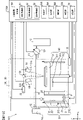
まず、図1および図2を参照して、造形装置1の構成を説明する。図1は造形装置1の構造を模式的に示すブロック図であり、図2は造形装置1が有する造形光学部35の具体的な構成と配置の一例を模式的に示す図である。なお、理解を容易にすることを目的として、図1、図2に示すように、X軸、Y軸およびZ軸からなる直交座標系を用いて以下の説明を行う。
-First Embodiment-
A modeling apparatus according to a first embodiment will be described with reference to the drawings. In the following description, a modeling apparatus that models a three-dimensional modeled object (three-dimensional modeled object) using a known powder bed fusion method (PBF) will be described as an example. The powder bed fusion method (PBF) is also called a powder sintering layered manufacturing method (SLS). In addition, the modeling apparatus is not limited to the powder bed fusion method (PBF), but other methods such as the directed energy deposition method (DED), the material injection method, the electron beam melting method (EBM), the fused deposition method (FDM), etc. It may also be an apparatus that models a three-dimensional model using the method.
First, the configuration of the modeling apparatus 1 will be described with reference to FIGS. 1 and 2. FIG. FIG. 1 is a block diagram schematically showing the structure of the modeling apparatus 1, and FIG. 2 is a diagram schematically showing an example of the specific configuration and arrangement of the modeling optical section 35 of the modeling apparatus 1. As shown in FIG. For the purpose of facilitating understanding, the following description will be made using an orthogonal coordinate system consisting of X, Y and Z axes as shown in FIGS.

造形装置1は、筐体10と、材料層形成部20と、造形部30と、演算装置50と、を備える。材料層形成部20は、材料供給槽21と、リコーター22とを備える。造形部30は、造形槽31と、造形光学部35とを備える。なお、説明の便宜上、材料層形成部20と造形部30とを別個の構成として分けて表すが、材料層形成部20と造形部30とを纏めて造形部と表すこともできる。 The modeling apparatus 1 includes a housing 10 , a material layer forming section 20 , a modeling section 30 and an arithmetic device 50 . The material layer forming section 20 includes a material supply tank 21 and a recoater 22 . The modeling section 30 includes a modeling tank 31 and a modeling optical section 35 . For convenience of explanation, the material layer forming part 20 and the shaping part 30 are separately represented as separate structures, but the material layer forming part 20 and the shaping part 30 can also be collectively represented as a shaping part.

材料供給槽21は、三次元造形物の造形するための材料である粉末材料Pを収容するための収容容器である。材料供給槽21の底面211は、たとえばピストン等により構成される駆動機構212により上下方向(Z方向)に沿って移動する。材料供給槽21の底面211がZ方向+側(上方)に向けて移動すると、底面211の上昇量に応じて材料供給槽21の内部の粉末材料Pが外部に押し出され、この押し出された粉末材料Pが後述するリコーター22によって後述する造形槽31に移送される。 The material supply tank 21 is a storage container for storing powder material P, which is a material for forming a three-dimensional modeled object. A bottom surface 211 of the material supply tank 21 is moved in the vertical direction (Z direction) by a drive mechanism 212 that is composed of, for example, a piston. When the bottom surface 211 of the material supply tank 21 moves toward the Z direction + side (upward), the powder material P inside the material supply tank 21 is pushed out according to the amount of rise of the bottom surface 211, and this pushed powder A material P is transferred to a modeling tank 31 described later by a recoater 22 described later.

材料供給槽21には、内部に収容された粉末材料Pを加熱するためのヒーター213が設けられる。ヒーター213は、後述する演算装置50による制御により、粉末材料Pが所望の温度となるように加熱する。ヒーター213は、既存の加熱方式のヒーターが用いられる。なお、ヒーター213には、ペルチェ素子等の温調素子を用いてもよい。このヒーター213は、材料供給槽21内の粉末材料Pを加熱することにより、粉末材料Pが造形槽31に移送され後述するレーザ光の照射により粉末材料Pが加熱される前に、予め粉末材料Pの温度を高くする。これにより、レーザ光の照射により加熱される粉末材料Pの温度が所望の温度(たとえば融点)まで上昇するために必要な熱量が少なくなる。また、ヒーター213は、吸湿度が高く流動性が低い粉末材料Pを加熱することにより、粉末材料Pの吸湿度を下げ流動性を高くする。これにより、粉末材料Pが造形槽31に移送されやすくなり、詳細を後述するようにして形成される材料層の平面度や積層厚や密度が均一になる。この結果、詳細を後述するようにして、材料層にレーザ光が照射されると、レーザ光の照射による材料層内部での温度上昇が均一となる。
なお、材料供給槽21は、Z方向下部から駆動機構212により粉末材料Pを外部に押し出すものに限定されない。材料供給槽21に収容された粉末材料Pが、材料供給槽21の下方(Z方向-側)に設けられたディスペンサに供給され、ディスペンサに供給された粉末材料Pはディスペンサの下部(Z方向-側)に設けられた排出部から造形槽31のベースプレート311上に落下し、落下した粉末材料Pは後述するリコーター22が有するブレード221の移動により均一な厚さに敷き詰めてもよい。
The material supply tank 21 is provided with a heater 213 for heating the powder material P accommodated therein. The heater 213 heats the powder material P to a desired temperature under the control of the computing device 50, which will be described later. As the heater 213, an existing heating type heater is used. A temperature control element such as a Peltier element may be used as the heater 213 . By heating the powder material P in the material supply tank 21, the heater 213 heats the powder material P in advance before the powder material P is transferred to the modeling tank 31 and heated by irradiation with a laser beam, which will be described later. Increase the temperature of P. As a result, the amount of heat required to raise the temperature of the powder material P heated by laser light irradiation to a desired temperature (for example, the melting point) is reduced. Further, the heater 213 heats the powder material P, which has high moisture absorption and low fluidity, thereby reducing the moisture absorption of the powder material P and increasing its fluidity. As a result, the powder material P is easily transferred to the modeling tank 31, and the flatness, lamination thickness, and density of the material layers formed as will be described in detail later become uniform. As a result, as will be described later in detail, when the material layer is irradiated with the laser beam, the temperature rise inside the material layer due to the irradiation of the laser beam becomes uniform.
Note that the material supply tank 21 is not limited to one that pushes out the powder material P from the lower part in the Z direction by the driving mechanism 212 . The powder material P contained in the material supply tank 21 is supplied to a dispenser provided below (Z direction - side) of the material supply tank 21, and the powder material P supplied to the dispenser is supplied to the lower part of the dispenser (Z direction - The powder material P that has fallen onto the base plate 311 of the modeling tank 31 from the discharge section provided on the side) may be spread to a uniform thickness by moving a blade 221 of the recoater 22, which will be described later.

粉末材料Pとして、たとえば、金属粉末や、樹脂粉末や、金属粒子に樹脂バインダをコートした粉末等が用いられる。金属粉末は、鉄系粉末を主成分とした粉末や、鉄系粉末に、ニッケル粉末、ニッケル系合成粉末、銅粉末、銅系合金粉末および黒鉛系粉末等のうちの少なくとも1種類以上を更に含む粉末でもよい。たとえば、平均粒径20μm程度の鉄系粉末の配合量が60~90重量%、ニッケル粉末およびニッケル系合金粉末の両方または一方の配合量が5~35重量%、銅粉末および銅系合金粉末の両方または一方の配合量が5~15重量%、ならびに黒鉛粉末の配合量が0.2~0.8重量%とした粉末が挙げられる。樹脂粉末としては、たとえば、平均粒径30μm~100μm程度のポリアミド、ポリプロピレン、ABS等の粉末を用いることができる。金属粒子に樹脂バインダをコートした粉末として、たとえば金属粒子の表面をフェノール樹脂やナイロン等の添加剤でコーティングしたものが用いられてもよい。また、粉末材料Pとしてセラミック粉末が用いられてもよい。セラミック粉末としては、アルミナやジルコニア等の酸化物や、窒化ケイ素等の窒化物の粉末でもよい。なお、粉末材料Pは、上述の材料以外であってもよい。粉末材料Pは、たとえば、既存の金属粉末、既存の樹脂粉末、又は既存のセラミック粉末でもよいし、既存の金属と既存の樹脂と既存のセラミックとの少なくとも2つの材料を組み合わせた粉末の材料であってもよい。
以下、粉末材料Pとして金属粉末が使用される場合を例に挙げて説明を行う。
As the powder material P, for example, metal powder, resin powder, powder obtained by coating metal particles with a resin binder, or the like is used. The metal powder is a powder containing iron-based powder as a main component, or the iron-based powder further includes at least one of nickel powder, nickel-based synthetic powder, copper powder, copper-based alloy powder, graphite-based powder, and the like. Powder may be used. For example, the amount of iron-based powder having an average particle size of about 20 μm is 60 to 90% by weight, the amount of nickel powder and/or nickel-based alloy powder is 5-35% by weight, and the amount of copper powder and copper-based alloy powder is 5 to 35% by weight. Powders containing 5 to 15% by weight of both or one of them and 0.2 to 0.8% by weight of graphite powder are included. As the resin powder, for example, a powder of polyamide, polypropylene, ABS, or the like having an average particle size of about 30 μm to 100 μm can be used. As a powder obtained by coating metal particles with a resin binder, for example, a powder obtained by coating the surface of metal particles with an additive such as phenol resin or nylon may be used. Ceramic powder may also be used as the powder material P. The ceramic powder may be an oxide such as alumina or zirconia or a nitride powder such as silicon nitride. Note that the powder material P may be a material other than the materials described above. The powder material P may be, for example, an existing metal powder, an existing resin powder, or an existing ceramic powder, or a powder material obtained by combining at least two materials of an existing metal, an existing resin, and an existing ceramic. There may be.
A case where metal powder is used as the powder material P will be described below as an example.

リコーター22は、材料層形成部材としてのブレード221と、駆動機構(不図示)と、ブレード装着部(不図示)とを有する。ブレード221は、たとえばY方向に沿って延在する板状の部材である。ブレード221は、材質や形状が異なる複数の種類の間で交換可能にブレード装着部に取り付けられる。駆動機構は、たとえばモータやX方向に沿って延伸するガイドレール等の駆動機構を有し、ブレード装着部をX方向に沿って移動させることによりブレード221をX方向に沿って図1の位置A(材料供給槽21のX方向-側端部)と位置B(造形槽31のX方向+側端部)との間を移動させる。このようにブレード221を移動させることにより、材料供給槽21に収容された粉末材料P(より詳しくは、材料供給槽21の底面211のZ方向+側(上方)への上昇量に応じて材料供給槽21の外部に押し出された粉末材料P)を、後述する造形部30の造形槽31に移送する。このとき、ブレード221は、粉末材料Pを下方(Z方向-側)に押し付けるように圧力を加えながら移動する。このブレード221の移動により、造形槽31に粉末材料Pが一定の厚さΔdにて敷き詰められて、表面(Z方向+側の面)が平らに整形された粉末床(パウダーベッド)と呼ばれる粉末材料の層(以後、材料層と呼ぶ)が形成される。すなわち、ブレード221は材料層形成部材として機能する。なお、ブレード221は、シリンダー等から構成される押圧機構(不図示)により、粉末材料Pに圧力を加えることができる。 The recoater 22 has a blade 221 as a material layer forming member, a drive mechanism (not shown), and a blade mounting portion (not shown). The blade 221 is, for example, a plate-like member extending along the Y direction. The blade 221 is attached to the blade mounting portion so as to be exchangeable among a plurality of types of different materials and shapes. The drive mechanism has, for example, a motor, a guide rail extending along the X direction, or the like, and moves the blade mounting portion along the X direction to move the blade 221 along the X direction to the position A in FIG. (X-direction negative side end of material supply tank 21) and position B (X-direction +side end of modeling tank 31). By moving the blade 221 in this way, the powder material P contained in the material supply tank 21 (more specifically, the material is The powder material P) extruded to the outside of the supply tank 21 is transferred to the modeling tank 31 of the modeling section 30, which will be described later. At this time, the blade 221 moves while applying pressure so as to press the powder material P downward (Z direction - side). By this movement of the blade 221, the powder material P is spread in the modeling tank 31 with a constant thickness Δd, and the surface (the surface on the positive side in the Z direction) is formed into a flat powder bed called a powder bed. A layer of material (hereinafter referred to as a material layer) is formed. That is, the blade 221 functions as a material layer forming member. The blade 221 can apply pressure to the powder material P by a pressing mechanism (not shown) composed of a cylinder or the like.

ブレード221が、後述するようにして造形された固化層の上部に粉末材料Pを移送させる場合には、先に形成された材料層へレーザ光が照射されることにより固化層が造形されてから所定の時間が経過した後、ブレード221は再び位置AからX方向に沿って移動して、粉末材料Pを固化層の上部に移送する。本明細書では、この所定の時間をブレード221の待機時間と呼ぶ。なお、上記の一定の厚さΔdとは、後述するベースプレート311上に粉末材料Pを移送した場合には、ベースプレート311の表面から材料層の表面(Z方向+側の面)までの厚さであり、後述するようして造形された固化層の上部(Z方向+側)に粉末材料Pが移送された場合には、固化層上部の面(Z方向+側の面)からその固化層の上部に形成された材料層の表面(Z方向+側の面)までの厚さである。
上述したブレード221の移動速度と、ブレード221により粉末材料に加える圧力と、ブレード221の待機時間とは演算装置50によって変更可能に制御される。なお、材料層の形成については、詳細を後述する。
なお、本実施の形態では、材料層形成部材として、板状のブレード221を例に挙げて説明を行うが、材料層形成部材は、ローラーやその他の材料層を形成するために使用可能な部材でよい。例えばローラーが材料層形成部材として用いられる場合には、ローラーは、回転軸がY軸方向に沿うように取り付けられ、駆動機構によってX方向に沿って移動するとき、回転しながら移動する。これにより、ローラーは、粉末材料Pに圧力を加えながら粉末材料Pを造形槽31に一定の厚さΔdで敷き詰める。
When the blade 221 transfers the powder material P to the upper part of the solidified layer formed as described later, the solidified layer is formed by irradiating the previously formed material layer with laser light. After a predetermined time has elapsed, the blade 221 moves again along the X direction from position A to transfer the powder material P to the top of the solidified layer. This predetermined time is referred to herein as the waiting time of the blade 221 . The constant thickness Δd is the thickness from the surface of the base plate 311 to the surface of the material layer (surface on the positive side in the Z direction) when the powder material P is transferred onto the base plate 311, which will be described later. There is, when the powder material P is transferred to the upper part (Z direction + side) of the solidified layer formed as described later, the solidified layer is transferred from the upper surface (Z direction + side) of the solidified layer It is the thickness up to the surface of the material layer formed above (the surface on the positive side in the Z direction).
The moving speed of the blade 221 , the pressure applied to the powder material by the blade 221 , and the waiting time of the blade 221 are variably controlled by the computing device 50 . Details of the formation of the material layer will be described later.
In this embodiment, the plate-shaped blade 221 is used as an example of the material layer forming member, but the material layer forming member is a roller or other member that can be used to form the material layer. OK. For example, when a roller is used as the material layer forming member, the roller is mounted so that the rotation axis extends along the Y-axis direction, and moves while rotating when moved along the X-direction by the driving mechanism. As a result, the roller spreads the powder material P in the modeling tank 31 with a constant thickness Δd while applying pressure to the powder material P. As shown in FIG.

造形部30の造形槽31は、材料層の形成と、形成された材料層を固化させた固化層の造形とを繰り返し、複数の固化層をZ方向に沿って積層することによって三次元状の造形物を造形するための造形作業用の容器である。本実施の形態における固化層は、後述するように、レーザ光の照射により材料層を形成する粉末材料Pを加熱し、加熱により粉末材料Pが溶融し、凝固して造形された層である。造形槽31の底面であるベースプレート311は、形成された材料層と、固化層とをZ方向-側から支持する支持部材である。ベースプレート311は、造形槽31に含まれるたとえばモータ等の駆動機構312により上下方向(Z方向)に沿って移動する。詳細を後述するように、ベースプレート311上に供給された粉末材料Pにより形成された材料層をレーザ光の照射により加熱して固化層が造形されると、ベースプレート311は下方向(Z方向-側)に移動し、次いで、固化層の上部表面(Z方向+側)に新たな材料層が形成される。この新たな材料層が固化されて新たな固化層が造形される。ベースプレート311は、材質やZ方向の厚みが異なる複数の種類のプレートの間で交換可能に造形槽31に取り付けられている。言い換えると、ベースプレート311は、剛性が異なる複数の種類のプレートの間で交換可能に造形槽31に取り付けられているとも言える。 The modeling tank 31 of the modeling unit 30 repeats the formation of a material layer and the modeling of a solidified layer obtained by solidifying the formed material layer. It is a container for modeling work for modeling a modeled object. As will be described later, the solidified layer in the present embodiment is a layer formed by heating the powder material P forming the material layer by irradiating it with a laser beam, and melting and solidifying the powder material P by heating. A base plate 311, which is the bottom surface of the modeling bath 31, is a support member that supports the formed material layer and the solidified layer from the Z direction - side. The base plate 311 is moved in the vertical direction (Z direction) by a drive mechanism 312 such as a motor included in the modeling bath 31 . As will be described later in detail, when a solidified layer is formed by heating the material layer formed of the powder material P supplied on the base plate 311 by irradiating the laser beam, the base plate 311 moves downward (Z direction - side ), and then a new layer of material is formed on the upper surface (+ side in the Z direction) of the solidified layer. This new layer of material is solidified to form a new solidified layer. The base plate 311 is attached to the modeling bath 31 so as to be exchangeable among a plurality of types of plates having different materials and thicknesses in the Z direction. In other words, it can be said that the base plate 311 is attached to the modeling tank 31 so as to be exchangeable among a plurality of types of plates having different rigidity.

ベースプレート311には、ベースプレート311を加熱するためのヒーター313が設けられる。ヒーター313は、後述する演算装置50による制御により、ベースプレート311に支持される材料層や固化層が所望の温度となるように加熱(予熱)する。ヒーター313は、既存の加熱方式のヒーターが用いられる。なお、ヒーター313として、ペルチェ素子などの温調素子が用いられてもよい。このヒーター313は、造形槽31内の材料層や固化層を加熱(予熱)する。ヒーター313は、材料層を構成する粉末材料Pがレーザ光の照射により加熱される前に、予め粉末材料Pを予熱して温度を高くする。これにより、レーザ光の照射により加熱される粉末材料Pの温度が所望の温度(たとえば融点)まで上昇するために必要な熱量が少なくなる。また、ヒーター313は、造形された固化層を加熱する。これにより、固化層の冷却時に残留応力が発生することが抑制されたり、固化層に発生してしまった残留応力が緩和される。 The base plate 311 is provided with a heater 313 for heating the base plate 311 . The heater 313 heats (preheats) the material layer and solidified layer supported by the base plate 311 to a desired temperature under the control of the arithmetic unit 50, which will be described later. As the heater 313, an existing heating type heater is used. A temperature control element such as a Peltier element may be used as the heater 313 . The heater 313 heats (preheats) the material layer and solidified layer in the modeling tank 31 . The heater 313 preheats the powder material P to raise the temperature thereof before the powder material P constituting the material layer is heated by the irradiation of the laser beam. As a result, the amount of heat required to raise the temperature of the powder material P heated by laser light irradiation to a desired temperature (for example, the melting point) is reduced. Also, the heater 313 heats the shaped solidified layer. As a result, generation of residual stress during cooling of the solidified layer is suppressed, and residual stress generated in the solidified layer is alleviated.

造形部30の造形光学部35は、取得部310と、照射部32と、走査部33と、フォーカスレンズ323とを有する。取得部310は、詳細を後述する撮像装置41と、二分岐光学系42と、色収差補正光学系43と、ハーフミラー301と、視野絞り302とを有する。取得部310は、粉末材料Pが溶融している溶融部を含む所定領域(粉末材料Pが溶融している溶融部、まだ溶融していない未溶融の粉末材料P(材料層)、溶融後に凝固した領域等)の少なくとも一部の情報を取得する(詳細は後述する)。なお、ハーフミラー301は、詳細を後述する造形光学部35の各構成の配置に応じて、取得部310に含まれなくてもよい。 The modeling optical section 35 of the modeling section 30 has an acquisition section 310 , an irradiation section 32 , a scanning section 33 , and a focus lens 323 . The acquisition unit 310 has an imaging device 41 , a bifurcation optical system 42 , a chromatic aberration correction optical system 43 , a half mirror 301 , and a field stop 302 , details of which will be described later. The acquisition unit 310 includes a predetermined region including a melted portion where the powder material P is melted (a melted portion where the powder material P is melted, an unmelted powder material P (material layer) that has not yet melted, and solidified after melting). area, etc.) is acquired (details will be described later). Note that the half mirror 301 may not be included in the acquisition unit 310 depending on the arrangement of each component of the shaping optical unit 35 whose details will be described later.

ここで、取得部310は、照射部32や走査部33と一体的に構成されているため、説明の便宜上、造形光学部35の一部(つまり、造形部30の一部)として説明する。しかしながら、取得部310は、当該取得部310以外の造形部30の構成(つまり、造形槽31、照射部32、フォーカスレンズ323、および走査部33)とは異なる機能(後述する、粉末材料Pが溶融している溶融部を含む所定領域の少なくとも一部の情報を取得する機能)を備える構成であることから、造形部30とは別個の構成として表すこともできる。この場合、造形部30は、照射部32と走査部33とフォーカスレンズ323とを有する造形光学部35と、造形槽31と、を有する構成となる。また、この場合、ハーフミラー301は、造形光学部35の一部でもあるため、取得部310ではなく、造形光学部35の構成として表すこともできる。 Here, since the acquisition unit 310 is configured integrally with the irradiation unit 32 and the scanning unit 33, for convenience of explanation, it will be described as part of the shaping optical unit 35 (that is, part of the shaping unit 30). However, the acquisition unit 310 has a different function (to be described later, the powder material P is function of acquiring information of at least a part of a predetermined region including a melted portion), it can also be represented as a separate configuration from the shaping portion 30 . In this case, the modeling section 30 is configured to have a modeling optical section 35 having an irradiation section 32 , a scanning section 33 and a focus lens 323 , and a modeling tank 31 . Further, in this case, the half mirror 301 is also a part of the optical shaping section 35 , so it can be represented as the configuration of the optical shaping section 35 instead of the acquisition section 310 .

照射部32は、一例として、材料層に照射して加熱するための照射光としてレーザ光を出射するレーザ発振器321と、レーザ発振器321から出射されたレーザ光を平行光にコリメートするコリメータレンズ322とを含む(図2参照)。レーザ発振器321として、たとえば炭酸ガスレーザや、Nd:YAGレーザや、ファイバレーザ等が使用可能である。
レーザ発振器321は、たとえば共振器ミラー等からなり、レーザ媒質に満たされた増幅器と、励起光源とを有する。励起光源の光によって励起されたレーザ媒質から発せられた光は、増幅器内における反射の繰り返しを経て発振し、レーザ発振器からレーザ光として出射する。レーザ発振器321は、レーザ光の発振モード(発振形態)として、励起光源を連続的に点灯させるCW(連続派)発振や、励起光源をパルス的に点灯し、励起光源の点灯時間幅と電流値を電気的に制御することによりレーザ光の出力波形を制御する通常パルス発振や、短時間でパルス幅の狭いピーク出力の大きなレーザ光を出射するQスイッチパルス発振等が含まれる。レーザ発振器321は、たとえば波長が1070nmのレーザ光を出射する。なお、レーザ発振器321は、他の波長の光、たとえば800nmより大きな赤外光や、400nm~800nmの範囲の可視光や、400nmより短い紫外光を出射してよい。なお、照射部32の具体的な構成については、説明を後述する。また、照射部32は、演算装置50からの制御により、公知の形状可変ミラー等によって、レーザ発振器321からのレーザ光の強度分布をガウシアン分布とトップハット分布等との間で切換えて出射する。
また、照射部32は、レーザ光に代えて既存の発光ダイオード(LED)や電子線、陽子線、中性子線などの既存の粒子線を材料層に照射し、粉末材料Pを加熱してもよい。本実施の形態においては、照射部32として、既存のレーザ光や既存の発光ダイオードや既存の粒子線等を含むエネルギー線を出射可能なものが適用される。
For example, the irradiation unit 32 includes a laser oscillator 321 that emits laser light as irradiation light for irradiating and heating a material layer, and a collimator lens 322 that collimates the laser light emitted from the laser oscillator 321 into parallel light. (see Figure 2). As the laser oscillator 321, for example, a carbon dioxide laser, an Nd:YAG laser, a fiber laser, or the like can be used.
The laser oscillator 321 is composed of, for example, a resonator mirror or the like, and has an amplifier filled with a laser medium and an excitation light source. The light emitted from the laser medium excited by the light of the excitation light source oscillates through repetition of reflection in the amplifier, and is emitted from the laser oscillator as laser light. The laser oscillator 321 has an oscillation mode (oscillation mode) of laser light, CW (continuous wave) oscillation that continuously lights the excitation light source, or pulse-lighting of the excitation light source, and the lighting time width and current value of the excitation light source. and Q-switched pulse oscillation that emits laser light with a narrow pulse width and high peak output in a short time. Laser oscillator 321 emits laser light with a wavelength of 1070 nm, for example. Note that the laser oscillator 321 may emit light of other wavelengths, such as infrared light longer than 800 nm, visible light in the range of 400 nm to 800 nm, and ultraviolet light shorter than 400 nm. A detailed configuration of the irradiation unit 32 will be described later. In addition, under the control of the arithmetic unit 50, the irradiation unit 32 switches the intensity distribution of the laser light from the laser oscillator 321 between a Gaussian distribution, a top hat distribution, and the like, and emits the laser light by using a known deformable mirror or the like.
Further, the irradiation unit 32 may irradiate the material layer with an existing light-emitting diode (LED), an existing particle beam such as an electron beam, a proton beam, or a neutron beam instead of the laser beam, thereby heating the powder material P. . In this embodiment, as the irradiation unit 32, one capable of emitting energy rays including existing laser light, existing light-emitting diodes, existing particle beams, and the like is applied.

走査部33は、ガルバノミラーにより構成され、照射部32から出射されたレーザ光を材料層上でX方向およびY方向の少なくとも一方に沿って走査する。なお、走査部33の具体的な構成については、説明を後述する。 The scanning unit 33 is composed of a galvanomirror, and scans the material layer along at least one of the X direction and the Y direction with the laser light emitted from the irradiation unit 32 . A detailed configuration of the scanning unit 33 will be described later.

撮像装置41は、照射部32からのレーザ光により照射され溶融した材料層の溶融部とその近傍の所定の領域を撮像して、材料層の溶融部とその近傍を含む所定の領域の像の画像データを生成する。生成される画像データは、材料層の溶融部とその近傍を含む所定の領域からの光を後述する撮像素子411により光電変換して得られた各画素の信号強度である。生成された画像データは、後述する演算装置50に出力される。なお、撮像装置41の具体的な構成については、説明を後述する。
なお、上述のように、造形光学部35は、材料層にレーザ光を照射する構成と、材料層の像を撮像する構成とを一部共有しているため、撮像光学系とも言うことができる。
The imaging device 41 captures an image of the melted portion of the material layer melted by irradiation with the laser beam from the irradiation unit 32 and a predetermined region in the vicinity thereof, and captures an image of the predetermined region including the melted portion of the material layer and the vicinity thereof. Generate image data. The generated image data is the signal intensity of each pixel obtained by photoelectrically converting light from a predetermined region including the melted portion of the material layer and its vicinity by the imaging device 411, which will be described later. The generated image data is output to the arithmetic device 50, which will be described later. A detailed configuration of the imaging device 41 will be described later.
As described above, the shaping optical unit 35 partially shares the configuration for irradiating the material layer with a laser beam and the configuration for capturing an image of the material layer, so it can also be called an imaging optical system. .

筐体10は、材料供給槽21と、リコーター22と、固化層が収容される造形槽31とを内部に収容する。なお、材料供給槽21の底面211を移動させる駆動機構212の一部や、造形槽31のベースプレート311を移動させる駆動機構312の一部は筐体10の内部に収容されていなくてもよい。筐体10には吸気口11と排気口12とが形成される。吸気口11には、たとえばアルゴンや窒素等の不活性ガスが充填されたタンク13がバルブ等の吸気装置131を介して接続される。排気口12には、たとえば真空ポンプ等を備える排気装置14が接続される。演算装置50に制御された排気装置14と吸気装置131とは、設定された筐体10内の圧力が得られるように、筐体10内部を排気する。また、吸気装置131は、タンク13に充填された不活性ガスを筐体10の内部に導入することにより、筐体10内の酸素濃度を下げる。筐体10内の酸素濃度が下がるので、粉末材料Pの酸化が防止される。筐体10の内部に導入される不活性ガスの流量および流速は、吸気装置131のバルブの開度および排気装置14の排気量により制御される。筐体10には、内部を加熱するヒーター15が設けられ、後述する演算装置50により制御されて筐体10の内部が所望の温度となるように加熱される。ヒーター15は、既存の加熱方式のヒーターが用いられる。なお、ヒーター15として、ペルチェ素子などの温調素子が用いられてもよい。このヒーター15は、筐体10内を加熱することにより、造形槽31内の材料層や固化層を加熱する。ヒーター15は、材料層を構成する粉末材料Pがレーザ光の照射により加熱される前に、粉末材料Pの温度を予め高くする。これにより、レーザ光に照射された粉末材料Pの温度が所望の温度(たとえば融点)まで上昇するため必要な熱量が少なくなる。 The housing 10 accommodates therein a material supply tank 21, a recoater 22, and a modeling tank 31 containing a solidified layer. Part of the drive mechanism 212 that moves the bottom surface 211 of the material supply tank 21 and part of the drive mechanism 312 that moves the base plate 311 of the modeling tank 31 may not be housed inside the housing 10 . An intake port 11 and an exhaust port 12 are formed in the housing 10 . A tank 13 filled with an inert gas such as argon or nitrogen is connected to the intake port 11 via an intake device 131 such as a valve. An exhaust device 14 including, for example, a vacuum pump is connected to the exhaust port 12 . The exhaust device 14 and the intake device 131 controlled by the computing device 50 exhaust the interior of the housing 10 so that the set pressure within the housing 10 is obtained. In addition, the intake device 131 reduces the oxygen concentration in the housing 10 by introducing the inert gas filled in the tank 13 into the housing 10 . Since the oxygen concentration in the housing 10 is lowered, the powder material P is prevented from being oxidized. The flow rate and flow velocity of the inert gas introduced into the housing 10 are controlled by the valve opening of the intake device 131 and the displacement of the exhaust device 14 . A heater 15 that heats the inside of the housing 10 is provided, and is controlled by an arithmetic unit 50 to be described later so that the inside of the housing 10 is heated to a desired temperature. As the heater 15, an existing heating type heater is used. A temperature control element such as a Peltier element may be used as the heater 15 . The heater 15 heats the material layer and solidified layer in the modeling tank 31 by heating the inside of the housing 10 . The heater 15 raises the temperature of the powder material P in advance before the powder material P forming the material layer is heated by the irradiation of the laser beam. As a result, the temperature of the powder material P irradiated with the laser light rises to a desired temperature (for example, the melting point), so the required amount of heat is reduced.

以上のようにして、筐体10内の酸素濃度、不活性ガスの流量および流速、不活性ガスの種類、筐体10内の圧力、筐体10内の温度を含む筐体10の内部の雰囲気が制御される。また、照射部32からのレーザ光を透過させるため、筐体10の上面(Z方向+側)のうちの少なくとも一部の領域はガラス等の透光性を有する部材により形成される。この一部の領域は、たとえば、走査部33から材料層上に向かうレーザ光の光路と交差する領域である。 As described above, the atmosphere inside the housing 10 including the oxygen concentration in the housing 10, the flow rate and flow rate of the inert gas, the type of inert gas, the pressure in the housing 10, and the temperature in the housing 10 is controlled. At least a part of the upper surface (+ side in the Z direction) of the housing 10 is made of a translucent member such as glass so that the laser beam from the irradiation unit 32 can pass therethrough. This partial area is, for example, an area that intersects with the optical path of the laser beam from the scanning unit 33 toward the material layer.

ここで、図2を参照しながら造形光学部35の具体的な構成と配置の一例について説明する。
図2に示すように、照射部32のレーザ発振器321からZ方向-側に向けて出射したレーザ光は、ハーフミラー301によりX方向+側へ反射され、フォーカスレンズ323を通過して走査部33に入射する。なお、照射部32からのレーザ光の出射方向はZ方向-側に限定されず、ハーフミラー301がレーザ光を反射する方向はX方向+側に限定されない。照射部32が配置される位置と、材料層の位置および/または造形光学部35の他の構成が配置される位置との関係に基づいて、レーザ光の出射方向やハーフミラー301の反射方向は適宜好ましい方向となるように決められる。
Here, an example of the specific configuration and arrangement of the shaping optical section 35 will be described with reference to FIG. 2 .
As shown in FIG. 2, the laser beam emitted from the laser oscillator 321 of the irradiation unit 32 toward the Z direction - side is reflected by the half mirror 301 toward the X direction + side, passes through the focus lens 323, and passes through the scanning unit 33. incident on The direction in which the laser light is emitted from the irradiation unit 32 is not limited to the negative side in the Z direction, and the direction in which the half mirror 301 reflects the laser light is not limited to the positive side in the X direction. Based on the relationship between the position where the irradiation unit 32 is arranged and the position of the material layer and/or the position where other components of the shaping optical unit 35 are arranged, the emission direction of the laser light and the reflection direction of the half mirror 301 It is determined so as to be a suitable direction.

フォーカスレンズ323は、凹レンズ323aと凸レンズ323bとを有する。後述するガルバノミラー331、332で反射したレーザ光の焦点位置(焦点距離)を調整するために、凹レンズ323aは、演算装置50に制御されて不図示の駆動機構によりX方向に沿って移動可能に構成されている。したがって、この凹レンズ323aのX方向の位置に応じて、材料層上のレーザ光の光束径(スポットサイズ)が調整できる。この場合、後述するガルバノミラー331、332の駆動(すなわち、ガルバノミラー331、332の角度の変化)により、レーザ光が材料層の表面に到達するまでに進む距離が変動するため、フォーカスレンズ323は、ガルバノミラー331、332で反射したレーザ光の集光点と、材料層の表面とが合うように、ガルバノミラー331、332の駆動に応じて、レーザ光の焦点位置を調整することができる。 The focus lens 323 has a concave lens 323a and a convex lens 323b. In order to adjust the focal position (focal length) of the laser beams reflected by the galvano mirrors 331 and 332, which will be described later, the concave lens 323a is controlled by the arithmetic device 50 and made movable along the X direction by a driving mechanism (not shown). It is configured. Therefore, the luminous flux diameter (spot size) of the laser light on the material layer can be adjusted according to the position of the concave lens 323a in the X direction. In this case, driving the galvanometer mirrors 331 and 332 (that is, changing the angle of the galvanometer mirrors 331 and 332) changes the distance traveled by the laser light until it reaches the surface of the material layer. , the focal position of the laser light can be adjusted according to the driving of the galvanometer mirrors 331 and 332 so that the focal point of the laser light reflected by the galvanometer mirrors 331 and 332 is aligned with the surface of the material layer.

また、必ずしもガルバノミラー331、332の駆動に伴い、レーザ光の集光点と材料層の表面とが合うように、レーザ光の焦点位置が調整されなくてもよい。例えば、材料層上におけるレーザ光の照射位置毎にレーザ光の光束径(スポットサイズ)を変更するように、ガルバノミラー331、332の駆動(ガルバノミラー331、332の角度の変化)に応じて、演算装置50に制御された不図示の駆動機構により凹レンズ323aの位置を制御してもよい。なお、凹レンズ323aが移動可能に構成されていなくてもよく、凸レンズ323bが不図示の駆動機構によりX方向に移動可能に構成されていてもよいし、凹レンズ323aと凸レンズ323bの両方のレンズが不図示の駆動機構によりX方向に移動可能に構成されていてもよい。また、フォーカスレンズ323は、凹レンズ323aと凸レンズ323bを含む所謂、ガリレオ型でなくてもよく、他の既存の光学系を採用することもできる。
なお、フォーカスレンズ323の凹レンズ323aや凸レンズ323bがX方向に移動可能に構成されるものに限定されない。フォーカスレンズ323が配置される位置と、造形光学部35の他の構成が配置される位置との関係に基づいて、凹レンズ323aや凸レンズ323bの移動方向は適宜好ましい方向となるように決められる。
Further, the focal position of the laser light does not necessarily have to be adjusted so that the condensing point of the laser light and the surface of the material layer coincide with the driving of the galvanometer mirrors 331 and 332 . For example, according to the driving of the galvanometer mirrors 331 and 332 (changes in the angles of the galvanometer mirrors 331 and 332) so as to change the beam diameter (spot size) of the laser beam for each irradiation position of the laser beam on the material layer, The position of the concave lens 323a may be controlled by a driving mechanism (not shown) controlled by the computing device 50. FIG. The concave lens 323a may not be movable, the convex lens 323b may be movable in the X direction by a driving mechanism (not shown), or both the concave lens 323a and the convex lens 323b may be movable. It may be configured to be movable in the X direction by a drive mechanism shown. Also, the focus lens 323 may not be of a so-called Galileo type including a concave lens 323a and a convex lens 323b, and other existing optical systems may be employed.
Note that the concave lens 323a and the convex lens 323b of the focus lens 323 are not limited to being movable in the X direction. Based on the relationship between the position where the focus lens 323 is arranged and the position where other components of the shaping optical section 35 are arranged, the moving directions of the concave lens 323a and the convex lens 323b are appropriately determined to be preferable directions.

走査部33は、ガルバノミラー331と332とを有する。ガルバノミラー331は、Z軸に対して所定の角度傾いた状態で配置される。ガルバノミラー331のZ軸に対する傾き角度は、演算装置50からの制御により変更される。ガルバノミラー331は、フォーカスレンズ323からX方向+側へ進むレーザ光を、ガルバノミラー331よりもZ方向+側に設けられたガルバノミラー332へ向けて反射する。 The scanning unit 33 has galvanometer mirrors 331 and 332 . The galvanomirror 331 is arranged in a state inclined at a predetermined angle with respect to the Z-axis. The tilt angle of the galvanomirror 331 with respect to the Z-axis is changed under control from the arithmetic device 50 . The galvanomirror 331 reflects the laser beam traveling from the focus lens 323 in the +X direction toward the galvanomirror 332 provided on the +Z side of the galvanomirror 331 .

ガルバノミラー332は、XY平面に対して所定の角度傾いた状態で配置される。ガルバノミラー332のXY平面に対する傾き角度は、演算装置50からの制御により変更される。ガルバノミラー331で反射されたレーザ光は、ガルバノミラー332で反射され、材料層の表面に導かれる。ガルバノミラー331のZ軸に対する傾き角度と、ガルバノミラー332のXY平面に対する傾き角度とが変更されることにより、レーザ光が照射される材料層上の位置がX軸およびY軸の少なくとも一方に沿って移動する。これにより、レーザ光に照射される材料層上での位置をXY平面上で移動、すなわち走査させることができる。
なお、ガルバノミラー331、332の配置や、ガルバノミラー331によるレーザ光の反射方向は上述した配置や反射方向に限定されない。走査部33が配置される位置と、造形光学部35の他の構成が配置される位置との関係に基づいて、ガルバノミラー331、332の配置や、ガルバノミラー331によるレーザ光の反射方向は適宜好ましい配置や反射方向となるように決められる。
The galvanomirror 332 is arranged in a state inclined at a predetermined angle with respect to the XY plane. The tilt angle of the galvanomirror 332 with respect to the XY plane is changed under control from the arithmetic device 50 . The laser light reflected by the galvanometer mirror 331 is reflected by the galvanometer mirror 332 and guided to the surface of the material layer. By changing the tilt angle of the galvanometer mirror 331 with respect to the Z-axis and the tilt angle of the galvanometer mirror 332 with respect to the XY plane, the position on the material layer irradiated with the laser light is shifted along at least one of the X-axis and the Y-axis. to move. Thereby, the position on the material layer irradiated with the laser light can be moved on the XY plane, that is, scanned.
The arrangement of the galvanometer mirrors 331 and 332 and the reflection direction of the laser beam by the galvanometer mirror 331 are not limited to the above-described arrangement and reflection direction. Based on the relationship between the position where the scanning unit 33 is arranged and the position where other components of the shaping optical unit 35 are arranged, the arrangement of the galvanometer mirrors 331 and 332 and the reflection direction of the laser beam by the galvanometer mirror 331 are appropriately determined. It is determined so as to obtain a preferable arrangement and reflection direction.

上記のガルバノミラー331、332で設定される走査角度量が増加すると、レーザ光の走査距離が増加する。走査距離は、レーザ光に照射される材料層上の位置(照射位置)がXY平面上で移動するときの照射位置の移動距離である。また、ガルバノミラー331、332の傾き角度を変更する速度が増加すると、レーザ光の走査速度が増加する。走査速度は、材料層上での照射位置がXY平面上で移動するときの速度のことである。すなわち、演算装置50は、ガルバノミラー331,332の走査角度量や変更速度を制御することにより、レーザ光の走査距離や走査速度を制御する。
ガルバノミラー331、332の傾き角度により材料層の表面上にてレーザ光の照射位置が決まる。後述する撮像装置41により撮像が行われた際には、生成された画像データは、照射位置情報と、時間情報とに関連付けされて記憶部58に記憶される。照射位置情報は、レーザ光の照射位置を示す情報である。上述したようにレーザ光の照射位置はガルバノミラー331、332の傾き角度により移動するので、エンコーダ等により検出されたガルバノミラー331、332の傾き角度に基づいて材料層上でのレーザ光の照射位置が算出される。また、画像データに関連付けされる照射位置情報は、ガルバノミラー331、332の傾き角度であってもよい。時間情報とは、レーザ光の照射開始時を基準として撮像装置41により撮像が行われたタイミングを示す時間情報である。
As the scanning angle amount set by the galvanomirrors 331 and 332 increases, the scanning distance of the laser light increases. The scanning distance is the movement distance of the irradiation position when the position on the material layer irradiated with the laser light (irradiation position) moves on the XY plane. Further, when the speed of changing the tilt angles of the galvanomirrors 331 and 332 increases, the scanning speed of the laser light increases. The scanning speed is the speed at which the irradiation position on the material layer moves on the XY plane. That is, the arithmetic device 50 controls the scanning distance and scanning speed of the laser light by controlling the scanning angle amount and changing speed of the galvanometer mirrors 331 and 332 .
The tilt angles of the galvanometer mirrors 331 and 332 determine the irradiation position of the laser light on the surface of the material layer. When an image is captured by the imaging device 41, which will be described later, the generated image data is stored in the storage unit 58 in association with irradiation position information and time information. The irradiation position information is information indicating the irradiation position of the laser beam. As described above, the irradiation position of the laser beam moves according to the tilt angles of the galvanometer mirrors 331 and 332. Therefore, the laser beam irradiation position on the material layer is determined based on the tilt angles of the galvanometer mirrors 331 and 332 detected by an encoder or the like. is calculated. Also, the irradiation position information associated with the image data may be the tilt angles of the galvanomirrors 331 and 332 . The time information is time information indicating the timing at which the imaging device 41 performs imaging with reference to the start of laser light irradiation.

なお、走査部33が上述したガルバノミラー331、332によって構成されるものに限定されない。たとえば、走査部33は、造形槽31のベースプレート311をX方向およびY方向の少なくとも一方に沿って移動させる駆動機構によって構成されてよい。この場合、駆動機構は、モータやX方向に延在するガイドレールやY方向に延在するガイドレール等により構成され、ベースプレート311をXY平面上で移動させる。これにより、レーザ光の照射位置と材料層とのXY平面上での相対的な位置関係が変更され、レーザ光が材料層上で走査される。この場合、上記のガルバノミラー331、332によるレーザ光のXY平面における照射位置の移動と、ベースプレート311の移動による材料層のXY平面における移動とが行われることによりレーザ光が走査されてもよい。また、上記のガルバノミラー331、332の傾き角度が固定され、ベースプレート311の移動による材料層のXY平面における移動のみが行われることによりレーザ光が走査されてもよい。レーザ光とベースプレート311(すなわち、材料層)とのXY平面上での相対的な位置関係を変更する構成は、上述の構成に限られず、他の既存の構成を適用することもできる。 It should be noted that the scanning unit 33 is not limited to the galvanometer mirrors 331 and 332 described above. For example, the scanning unit 33 may be configured by a drive mechanism that moves the base plate 311 of the modeling tank 31 along at least one of the X direction and the Y direction. In this case, the driving mechanism includes a motor, a guide rail extending in the X direction, a guide rail extending in the Y direction, and the like, and moves the base plate 311 on the XY plane. As a result, the relative positional relationship on the XY plane between the irradiation position of the laser beam and the material layer is changed, and the material layer is scanned with the laser beam. In this case, the laser light may be scanned by moving the irradiation position of the laser light on the XY plane by the galvanometer mirrors 331 and 332 and moving the material layer on the XY plane by moving the base plate 311 . Alternatively, the laser beam may be scanned by fixing the inclination angles of the galvanomirrors 331 and 332 and only moving the material layer in the XY plane by moving the base plate 311 . The configuration for changing the relative positional relationship on the XY plane between the laser light and the base plate 311 (that is, the material layer) is not limited to the configuration described above, and other existing configurations can be applied.

材料層上のうち、粉末材料Pが溶融している溶融部を含む所定領域(粉末材料Pが溶融している溶融部、まだ溶融していない未溶融の粉末材料P(材料層)、溶融後に凝固した領域等)の少なくとも一部の領域からの光(以降、説明の便宜上、熱放射光と称する)は、レーザ光と同軸の光路を反対方向に進む。すなわち、熱放射光は、材料層表面からZ方向+側に向けて進み、ガルバノミラー332によりガルバノミラー331に向けて反射され、ガルバノミラー331にてX方向-側に反射される。X方向-側に進む所定領域からの光は、フォーカスレンズ323に入射し、凸レンズ323bと凹レンズ323aを通過して、平行光束となる。フォーカスレンズ323を通過した熱放射光は、ハーフミラー301を透過し、X方向-側へ進み、色収差補正光学系43に入射する。なお、レーザ光を反射し、熱放射光を透過する光学部材はハーフミラーでなくてもよい。たとえば、ダイクロックミラーなどの既存の光学部材でもよい。 On the material layer, a predetermined region including a melted portion where the powder material P is melted (a melted portion where the powder material P is melted, an unmelted powder material P (material layer) that has not yet melted, and after melting The light from at least a portion of the solidified region (such as the solidified region) (hereinafter referred to as thermal emission light for convenience of explanation) travels in the opposite direction along the optical path coaxial with the laser light. That is, the thermal radiation travels from the surface of the material layer toward the + side in the Z direction, is reflected by the galvano mirror 332 toward the galvano mirror 331 , and is reflected by the galvano mirror 331 toward the − side in the X direction. Light from a predetermined area traveling in the X direction - side enters the focus lens 323, passes through the convex lens 323b and the concave lens 323a, and becomes a parallel light beam. After passing through the focus lens 323 , the thermal radiation light passes through the half mirror 301 , travels in the − direction in the X direction, and enters the chromatic aberration correction optical system 43 . It should be noted that the optical member that reflects laser light and transmits thermal radiation light may not be a half mirror. For example, an existing optical member such as a dichroic mirror may be used.

色収差補正光学系43は、フォーカスレンズ323の通過により、熱放射光に発生している軸上色収差、倍率色収差等を補正する。色収差補正光学系43は、第1レンズ431と、第2レンズ432と、第3レンズ433とを含み、この順序にてX方向+側から配置される。第1レンズ431と第2レンズ432とは、それぞれ凸レンズと凹レンズとを組み合わせた接合レンズである。第1レンズ431は正の屈折率を有し、第2レンズ432は負の屈折率を有し、第3レンズは正の屈折率を有する。第1レンズ431と第2レンズ432とは、ハーフミラー301を透過して入射した熱放射光を平行光束の状態でX方向-側の第3レンズ433に入射させ、第3レンズ433はこの平行光束を集光して一次像面を形成させる。この一次像面で軸上色収差や倍率色収差が生じないように第1レンズ431と第2レンズ432と第3レンズ433との分散が決定される。この場合、第1レンズ431および第2レンズ432を透過した熱放射光に含まれる色収差が、第3レンズ433の集光により生じる色収差によって打ち消されるように、各レンズの分散が決まっている。
なお、色収差補正光学系43の第1レンズ431、第2レンズ432、第3レンズ433がX方向に沿って配置されるものに限定されない。色収差補正光学系43が配置される位置と、造形光学部35の他の構成が配置される位置との関係に基づいて、第1レンズ431、第2レンズ432、第3レンズ433が配置される方向は適宜好ましい方向となるように決められる。
The chromatic aberration correcting optical system 43 corrects axial chromatic aberration, chromatic aberration of magnification, etc. occurring in the thermal radiation light as it passes through the focus lens 323 . The chromatic aberration correction optical system 43 includes a first lens 431, a second lens 432, and a third lens 433, which are arranged in this order from the + side in the X direction. The first lens 431 and the second lens 432 are respectively cemented lenses that combine a convex lens and a concave lens. The first lens 431 has a positive refractive index, the second lens 432 has a negative refractive index, and the third lens has a positive refractive index. The first lens 431 and the second lens 432 cause the thermal radiation light that has passed through the half mirror 301 to enter the third lens 433 on the − side in the X direction in the state of a parallel light flux. A light beam is condensed to form a primary image plane. The dispersion of the first lens 431, the second lens 432, and the third lens 433 is determined so that longitudinal chromatic aberration and chromatic aberration of magnification do not occur on this primary image plane. In this case, the dispersion of each lens is determined so that the chromatic aberration contained in the thermal radiation transmitted through the first lens 431 and the second lens 432 is canceled by the chromatic aberration caused by the condensing of the third lens 433 .
Note that the first lens 431, the second lens 432, and the third lens 433 of the chromatic aberration correction optical system 43 are not limited to being arranged along the X direction. A first lens 431, a second lens 432, and a third lens 433 are arranged based on the relationship between the position where the chromatic aberration correction optical system 43 is arranged and the position where other components of the shaping optical section 35 are arranged. The direction is appropriately determined so as to be a preferred direction.

一次像面には視野絞り302が配置される。熱放射光が視野絞り302に設けられた開口をX方向-側へ向けて通過することにより、後述する撮像装置41に入射する光束が結像して生成される画像(画像データ)の視野が制限される。本実施の形態では、視野絞り302の開口は、レーザ光の照射位置を含む所定領域の画像(画像データ)が生成されるようにその開口の大きさが決定されている。これにより、材料層上の所定領域外の像が画像(画像データ)上に含まれることが抑制される。視野絞り302を通過した熱放射光は、視野絞り302のX方向-側に配置された二分岐光学系42に入射する。 A field stop 302 is arranged on the primary image plane. The field of view of the image (image data) generated by imaging the light flux incident on the imaging device 41 described later by the thermal radiation passing through the aperture provided in the field stop 302 toward the X direction - side. Limited. In this embodiment, the size of the aperture of the field stop 302 is determined so that an image (image data) of a predetermined area including the irradiation position of the laser beam is generated. This prevents the image (image data) from including an image outside the predetermined region on the material layer. The thermal radiation light that has passed through the field stop 302 is incident on the bifurcating optical system 42 arranged on the - side of the field stop 302 in the X direction.

二分岐光学系42は、対物レンズ421と、光束分割部422と、光束偏向部423、424と、光束合成部425と、結像レンズ426と、第1フィルタ427と、第2フィルタ428とを有する。対物レンズ421はコリメートレンズであり、視野絞り302から到達した熱放射光を平行光にコリメートする。光束分割部422は、たとえばダイクロックミラーやビームスプリッター等により構成され、熱放射光のうち特定波長の光束を透過し、特定波長以外の光束を反射する。本実施の形態では、光束分割部422は、入射した熱放射光のうち波長がλ1の光を透過して、X方向-側に設けられた第1フィルタ427へ導き、波長がλ2の光を反射して、Z方向+側に設けられた光束偏向部423へ導く。光束偏向部423は、たとえばダイクロイックミラー等により構成され、波長がλ2の光を反射して、X方向-側に設けられた第2フィルタ428へ導く。なお、本実施の形態では、波長λ1を、たとえば1250[nm]とし、波長λ2を、たとえば1600[nm]であるものとして説明を行うが、波長λ1、λ2は上記の値に限定されるものではない。 The bifurcating optical system 42 includes an objective lens 421, a beam splitter 422, beam deflectors 423 and 424, a beam combiner 425, an imaging lens 426, a first filter 427, and a second filter 428. have. The objective lens 421 is a collimating lens, and collimates the thermal radiation light arriving from the field stop 302 into parallel light. The beam splitter 422 is composed of, for example, a dichroic mirror, a beam splitter, or the like, and transmits a beam of thermal radiation with a specific wavelength and reflects a beam with a wavelength other than the specific wavelength. In the present embodiment, the beam splitter 422 transmits the light with a wavelength of λ1 among the incident thermal radiation light, guides it to the first filter 427 provided on the − side in the X direction, and transmits the light with a wavelength of λ2. The light is reflected and guided to the light flux deflector 423 provided on the positive side in the Z direction. The beam deflector 423 is composed of, for example, a dichroic mirror or the like, reflects the light with a wavelength of λ2, and guides it to the second filter 428 provided on the negative side in the X direction. In this embodiment, the wavelength λ1 is assumed to be 1250 [nm], and the wavelength λ2 is assumed to be 1600 [nm]. However, the wavelengths λ1 and λ2 are limited to the above values. is not.

第1フィルタ427は、波長がλ1の光を透過させるバンドパスフィルタである。光束分割部422を透過した波長がλ1の光は、第1フィルタ427を透過し、X方向-側に配置された光束偏向部424に入射する。第2フィルタ428は、波長がλ2の光を透過させるバンドパスフィルタである。光束偏向部423で反射した波長がλ2の光は、第2フィルタ428を透過し、光束合成部425に入射する。光束偏向部424は、たとえばダイクロイックミラー等により構成され、光束の反射面はXY平面に対して所定の傾き角度となるように配置される。 The first filter 427 is a bandpass filter that transmits light with a wavelength of λ1. The light having a wavelength of λ1 that has passed through the beam splitter 422 passes through the first filter 427 and enters the beam deflector 424 arranged on the − side in the X direction. The second filter 428 is a bandpass filter that transmits light with a wavelength of λ2. The light having a wavelength of λ2 reflected by the beam deflector 423 passes through the second filter 428 and enters the beam combiner 425 . The beam deflector 424 is composed of, for example, a dichroic mirror or the like, and is arranged so that the reflection surface of the beam has a predetermined tilt angle with respect to the XY plane.

光束合成部425は、たとえばダイクロイックミラー等により構成され、光束の反射面はXY平面に対して所定の傾き角度となるように配置される。光束偏向部424で反射された波長がλ1の光は、Z方向+側に向けて進み、光束合成部425を透過して結像レンズ426により集光されて撮像装置41に入射する。光束合成部425に入射した波長がλ2の光は、光束合成部425で反射された後に、Z方向+側へ向けて進み、結像レンズ426により集光されて撮像装置41に入射する。ここで、光束偏向部424の反射面の傾き角度と光束合成部425の反射面の傾き角度とは互いに異なる角度となるように配置される。このため、光束偏向部424からの波長がλ1の光と、光束合成部425からの波長がλ2の光とは、結像レンズ426に対して異なる角度で入射することとなり、後述する撮像装置41が有する撮像素子411の撮像面上で異なる位置に集光する。 The beam synthesizing unit 425 is composed of, for example, a dichroic mirror or the like, and is arranged so that the reflection surface of the beam is at a predetermined tilt angle with respect to the XY plane. The light with a wavelength of λ1 reflected by the beam deflector 424 travels in the positive direction in the Z direction, passes through the beam combiner 425 , is condensed by the imaging lens 426 , and enters the imaging device 41 . The light having a wavelength of λ2 that has entered the beam synthesizing unit 425 is reflected by the beam synthesizing unit 425 , travels toward the + side in the Z direction, is condensed by the imaging lens 426 , and enters the imaging device 41 . Here, the inclination angle of the reflective surface of the beam deflector 424 and the inclination angle of the reflective surface of the beam combiner 425 are arranged to be different angles. Therefore, the light with a wavelength of λ1 from the beam deflection unit 424 and the light with a wavelength of λ2 from the beam combining unit 425 are incident on the imaging lens 426 at different angles. are condensed at different positions on the imaging surface of the imaging element 411 of .

本実施の形態においては、光束偏向部424と光束合成部425の反射面がXY平面となす角度が変更可能に構成される。すなわち、光束偏向部424と光束合成部425の反射面を駆動させる駆動機構(不図示)が設けられ、駆動機構は演算装置50からの制御に従って、光束偏向部424と光束合成部425の反射面を駆動して、反射面がXY平面となす角度を変更する。これにより、波長λ1の光と波長λ2の光との撮像素子411上への入射位置がリアルタイムに変更される。 In the present embodiment, the angle formed by the reflecting surfaces of the beam deflector 424 and the beam combiner 425 with respect to the XY plane can be changed. That is, a drive mechanism (not shown) is provided for driving the reflecting surfaces of the beam deflector 424 and the beam combiner 425 . to change the angle formed by the reflective surface with the XY plane. As a result, the incident positions of the light with the wavelength λ1 and the light with the wavelength λ2 on the imaging device 411 are changed in real time.

なお、上述した光束分割部422の反射面と、光束偏向部423の反射面とがXY平面となす角度が変更可能に構成されてもよい。すなわち、光束分割部422の反射面と、光束偏向部423の反射面を駆動させる駆動機構(不図示)が設けられ、駆動機構は演算装置50からの制御に従って、光束分割部422の反射面と、光束偏向部423の反射面を駆動して、反射面がXY平面となす角度を変更してよい。また、光束分割部422の反射面と、光束偏向部423の反射面とが駆動機構により駆動される例に限定されず、光束分割部422の反射面と、光束偏向部423の反射面とがユーザにより手動で調整されてもよい。この手動による調整は、たとえば造形装置1を納入した際の装置の立ち上げ時や、造形装置1のメンテナンスの時に行われる。
また、二分岐光学系42の各構成の配置や、熱放射光の反射方向は、上述した配置や反射方向に限定されない。二分岐光学系42が配置される位置と、造形光学部35の他の構成が配置される位置との関係に基づいて、二分岐光学系42の各構成の配置や、熱放射光の反射方向は適宜好ましい配置や反射方向となるように決められる。
It should be noted that the angle formed by the reflective surface of the beam splitter 422 and the reflective surface of the beam deflector 423 with respect to the XY plane may be changeable. That is, a driving mechanism (not shown) is provided for driving the reflecting surface of the beam splitting section 422 and the reflecting surface of the beam deflecting section 423 . , the reflecting surface of the beam deflector 423 may be driven to change the angle formed by the reflecting surface with the XY plane. Further, the reflective surface of beam splitter 422 and the reflective surface of beam deflector 423 are not limited to the example in which the driving mechanism drives the reflective surface of beam splitter 422 and the reflective surface of beam deflector 423. It may be manually adjusted by the user. This manual adjustment is performed, for example, when starting up the modeling apparatus 1 after delivery, or during maintenance of the modeling apparatus 1 .
Also, the arrangement of each component of the bifurcating optical system 42 and the reflection direction of the thermally emitted light are not limited to the arrangement and the reflection direction described above. Based on the relationship between the position where the bifurcating optical system 42 is arranged and the position where other components of the shaping optical unit 35 are arranged, the arrangement of each component of the bifurcating optical system 42 and the reflection direction of the thermal radiation light is appropriately determined so as to have a preferable arrangement and reflection direction.

撮像装置41は、たとえばCMOS、CCD等により構成される撮像素子411や、撮像素子411で光電変換された画像信号を読み出す読出し回路や、撮像素子411の駆動を制御する制御回路等を有する。撮像装置41に入射した熱放射光は、結像レンズ426により撮像素子411の撮像面上に集光する。撮像装置41は、入射した光束を光電変換し、画像データを生成して演算装置50に出力する。
上述したように、光束偏向部424の反射面の傾き角度と光束合成部425の反射面の傾き角度とは互いに異なる角度となるように配置されている。このため、材料層の所定領域からの熱放射光のうち、光束偏向部424で反射された波長λ1の光と、光束合成部425で反射された波長λ2の光とは、結像レンズ426に対して異なる角度で入射することとなり、撮像素子411の撮像面上の異なる位置に集光する。すなわち、材料層の所定領域からの熱放射光のうち波長の異なる2つの光によるそれぞれの像が、同一画像上の(同一画像データ上の)異なる位置に現れる。
The imaging device 41 has an imaging element 411 configured by, for example, CMOS, CCD, or the like, a readout circuit for reading out image signals photoelectrically converted by the imaging element 411, a control circuit for controlling driving of the imaging element 411, and the like. The thermal radiation light incident on the imaging device 41 is condensed on the imaging surface of the imaging element 411 by the imaging lens 426 . The imaging device 41 photoelectrically converts the incident light flux, generates image data, and outputs the image data to the arithmetic device 50 .
As described above, the inclination angle of the reflecting surface of the beam deflecting section 424 and the inclination angle of the reflecting surface of the beam combining section 425 are arranged to be different angles. For this reason, among the thermal radiation light from the predetermined region of the material layer, the light with wavelength λ1 reflected by the light flux deflector 424 and the light with wavelength λ2 reflected by the light flux combiner 425 are reflected by the imaging lens 426. In contrast, the light beams are incident at different angles, and converge at different positions on the imaging surface of the imaging element 411 . That is, images of two different wavelengths of thermal radiation from a predetermined region of the material layer appear at different positions on the same image (on the same image data).

なお、上述したように、光束偏向部422、423の反射面がXY平面となす角度と、光束偏向部424、光束合成部425の反射面がXY平面となす角度とが変更可能である。このため、演算装置50が、光束偏向部424、光束合成部425の反射面がXY平面となす角度とを制御することにより、熱放射光のうち波長λ1の光が撮像素子411上で集光する位置と、波長λ2の光が撮像素子411上で集光する位置との間の相対的な位置関係の調整が可能になる。なお、上述したように、光束分割部422の反射面と、光束偏向部423の反射面との角度が変更可能な場合には、光束分割部422の反射面と、光束偏向部423の反射面との角度を変更することによっても、波長λ1の光と波長λ2の光が撮像素子411上で集光する位置の調整が可能になる。 As described above, the angle formed by the reflective surfaces of the beam deflectors 422 and 423 with the XY plane and the angle formed by the reflective surfaces of the beam deflector 424 and the beam combiner 425 with the XY plane can be changed. For this reason, the calculation device 50 controls the angles formed by the reflecting surfaces of the light beam deflector 424 and the light beam combiner 425 with respect to the XY plane, so that the light of wavelength λ1 among the thermally emitted light is condensed on the imaging element 411. It is possible to adjust the relative positional relationship between the position where the light of the wavelength λ2 is focused and the position where the light of the wavelength λ2 is condensed on the image sensor 411 . As described above, when the angle between the reflecting surface of the beam splitting section 422 and the reflecting surface of the beam deflecting section 423 can be changed, the reflecting surface of the beam splitting section 422 and the reflecting surface of the beam deflecting section 423 It is also possible to adjust the positions at which the light of wavelength λ1 and the light of wavelength λ2 converge on the imaging element 411 by changing the angle between and.

図2に示す上述した構成を有することにより、レーザ光を照射させるための光学系と、撮像装置41で撮像するための光学系とが同軸に配置される。これにより、光学系の構成が簡素になり装置の大型化が抑制される。
また、二分岐光学系42が設けられることにより、異なる2つの波長λ1とλ2の光が撮像素子411の異なる位置に集光される。すなわち、粉末材料Pのうち溶融している溶融部を含む所定領域(粉末材料Pが溶融している溶融部、まだ溶融していない未溶融の粉末材料P(材料層)、溶融後に凝固した領域等)からの熱放射光の波長の異なる2つの光によるそれぞれの像が、同一画像上(同一画像データ上)の異なる位置に現れる。後述する演算装置50の検出部54は、後述する公知の二色法を用いて、この同一画像(同一画像データ)上の異なる位置の像のそれぞれの輝度情報の比を、粉末材料Pのうち溶融している溶融部を含む所定領域(粉末材料Pが溶融している溶融部、まだ溶融していない未溶融の粉末材料P(材料層)、溶融後に凝固した領域等)の温度に換算する。ここで、輝度情報とは、輝度値や輝度に関する値である。レーザ光が照射された材料層では、詳細を後述するように、粉末材料Pが溶融した領域と、また溶融していない未溶融の粉末材料Pと、溶融後に凝固した領域とが存在するため相状態が異なる。このため、材料層の所定領域内では相状態ごとに光の放射率が異なる。また、粉末材料Pの種類によっても光の放射率が異なる。
With the configuration shown in FIG. 2 and described above, the optical system for irradiating laser light and the optical system for imaging with the imaging device 41 are arranged coaxially. This simplifies the configuration of the optical system and suppresses an increase in the size of the device.
Also, by providing the bifurcating optical system 42 , light beams with two different wavelengths λ 1 and λ 2 are condensed at different positions of the imaging device 411 . That is, a predetermined region including a melted portion of the powder material P (a melted portion where the powder material P is melted, an unmelted powder material P (material layer) that has not yet melted, and a region solidified after melting ) appear at different positions on the same image (on the same image data). The detection unit 54 of the arithmetic device 50, which will be described later, uses a known two-color method, which will be described later, to determine the ratio of luminance information of the images at different positions on the same image (same image data). Convert to the temperature of a predetermined area including a melted melted area (melted area where the powder material P is melted, unmelted powder material P (material layer) that has not yet melted, area solidified after melting, etc.) . Here, the luminance information is a luminance value or a value related to luminance. In the material layer irradiated with the laser beam, as will be described later in detail, there are a region where the powder material P is melted, an unmelted powder material P that is not melted, and a region where the powder material P is solidified after melting. Different state. Therefore, the emissivity of light differs for each phase state within a given region of the material layer. Moreover, the emissivity of light also differs depending on the type of the powder material P.

また、詳細を後述するように、レーザ光が照射されることにより粉末材料Pが溶融している領域からはヒュームが発生する。ヒュームは、レーザ光の照射による加熱で粉末材料Pが蒸気となり、その蒸気が空気中で冷却されて固体となって浮遊する多数の細かい粒子である。2つの波長を含む熱放射光はヒュームによる散乱により減衰する。しかし、二色法においては、波長λ1の光に基づいて生成された画像データの輝度情報と波長λ2の光に基づいて生成された画像データの輝度情報との比(例えば、輝度値の比)に基づいて、温度に換算するので、粉末材料Pのうち溶融している溶融部を含む所定領域(粉末材料Pが溶融している溶融部、まだ溶融していない未溶融の粉末材料P(材料層)、溶融後に凝固した領域等)の放射率や2つの波長を含む熱放射光はヒュームによる散乱の影響を受けない。このため、撮像装置41で生成された画像データに基づいて、レーザ光に照射されている粉末材料Pの状態や、ヒューム等の影響を受けることなく材料層の温度に関する情報が取得される。 Further, as will be described later in detail, fumes are generated from the region where the powder material P is melted by the irradiation of the laser beam. The fumes are a large number of fine particles floating in a solid form when the powder material P is heated by the irradiation of the laser beam to vaporize and the vapor is cooled in the air. Thermal radiation containing two wavelengths is attenuated by scattering by fumes. However, in the two-color method, the ratio of the luminance information of the image data generated based on the light of the wavelength λ1 to the luminance information of the image data generated based on the light of the wavelength λ2 (for example, the ratio of the luminance values) is converted into a temperature based on the above, a predetermined region including a melted portion of the powder material P (a melted portion where the powder material P is melted, an unmelted powder material P that has not yet melted (material layer), solidified regions after melting, etc.) and the thermal radiation containing two wavelengths are not affected by fume scattering. Therefore, based on the image data generated by the imaging device 41, information about the state of the powder material P irradiated with the laser light and the temperature of the material layer can be obtained without being affected by fume or the like.

なお、造形光学部35の構成と配置は、上記の図2に示す例に限定されない。
たとえば、取得部310が2つの撮像装置41を有し、一方の撮像装置で熱放射光のうちの波長λ1の光を撮像し、他方の撮像装置で熱放射光のうちの波長λ2の光を撮像してよい。一方の撮像装置が有する撮像素子の撮像面はYZ平面に平行であり、他方の撮像装置が有する撮像素子の撮像面はXY平面に平行となるように2つの撮像装置が配置される。二分岐光学系42は、図2に示す、光束分割部422と、第1フィルタ427と、第2フィルタ428とを有する。また、図2に示す視野絞り302は設けられない。色収差補正光学系43の第3レンズ433は、2つの撮像装置41のそれぞれの前面に配置される。すなわち、色収差補正光学系43の第2レンズ432と第3レンズ433との間に、二分岐光学系42の第1フィルタ427、第2フィルタ428および光束分割部422が配置される。色収差補正光学系43の第1レンズ431および第2レンズ432を通過した光束は、光束分割部422により波長λ1の光が透過して第1フィルタ427を透過してX方向-側へ進み、一方の第3レンズ433により一方の撮像装置の撮像素子に集光する。光束分割部422により反射された波長λ2の光はZ方向+側へ進み、第2フィルタ428を透過し、他方の第3レンズ433により他方の撮像装置の撮像素子に集光する。これにより、それぞれの撮像装置は、互いに異なる波長ごとの画像データの生成が可能になる。
The configuration and arrangement of the shaping optical unit 35 are not limited to the example shown in FIG. 2 above.
For example, the acquisition unit 310 has two imaging devices 41, one of which captures the light of wavelength λ1 out of the thermal radiation, and the other captures the light of wavelength λ2 out of the thermal radiation. You can take an image. The two imaging devices are arranged such that the imaging surface of the imaging device of one imaging device is parallel to the YZ plane, and the imaging surface of the imaging device of the other imaging device is parallel to the XY plane. The bifurcating optical system 42 has a beam splitter 422, a first filter 427, and a second filter 428 shown in FIG. Also, the field stop 302 shown in FIG. 2 is not provided. The third lens 433 of the chromatic aberration correction optical system 43 is arranged in front of each of the two imaging devices 41 . That is, the first filter 427 , the second filter 428 and the beam splitter 422 of the bifurcation optical system 42 are arranged between the second lens 432 and the third lens 433 of the chromatic aberration correction optical system 43 . After passing through the first lens 431 and the second lens 432 of the chromatic aberration correction optical system 43, the light beam having the wavelength λ1 is transmitted by the beam splitting unit 422, passes through the first filter 427, and travels to the X direction - side. The third lens 433 converges the light on the imaging element of one of the imaging devices. The light of wavelength λ2 reflected by the beam splitting section 422 travels in the + direction in the Z direction, passes through the second filter 428, and is condensed by the other third lens 433 onto the imaging device of the other imaging device. This enables each imaging device to generate image data for each different wavelength.

また、取得部310は、例えば、図2に示す二分岐光学系42に代えて、透過する光の波長を切り替え可能なフィルタを用いてよい。このフィルタは、色収差補正光学系43の第2レンズ432と第3レンズ433との間に配置され、波長λ1の光を透過する領域(第1領域)と、波長λ2の光を透過する領域(第2領域)とを有する。フィルタの第1領域と第2領域とは、所定の時間間隔ごとに、熱放射光の光路上に交互に挿入される。たとえば、円板状の部材(ターレット)に波長透過率の異なる複数のフィルタが設けられ、ターレットの面がYZ平面と平行に配置され、不図示の駆動機構によりターレットの中心を回転中心として回転可能に構成される。例えば、ターレットに波長透過率の異なる複数のフィルタとして、第1フィルタと第2フィルタとが設けられているとすると、駆動機構によりターレットが回転すると、回転速度に応じた時間間隔で、第1フィルタと第2フィルタとが熱放射光の光路上に交互に挿入される。このため、第1フィルタが光路上に挿入されている間は、熱放射光のうち波長λ1の光が透過して第3レンズ433により撮像装置41の撮像素子411に集光し、第2フィルタが光路上に挿入されている間は、波長λ2の光が透過して第3レンズ433により撮像素子411に集光する。これにより、ターレットの回転速度に応じた時間間隔ごとに、撮像装置41は、波長λ1の光に基づく画像データの生成と、波長λ2の光に基づく画像データの生成とを行う。なお、この場合には、図2に示す視野絞り302は設けられない。これにより、撮像装置41は、異なる波長ごとの画像データをターレットの回転速度に応じた時間間隔ごとに生成することができる。
または、撮像装置41の撮像素子411上に、撮像素子411を構成する画素の配置に応じて、波長λ1と波長λ2のそれぞれの波長を選択するためのフィルタが配置されてもよい。この場合、図2に示す二分岐光学系42、視野絞り302は設けられない。これにより、波長λ1とλ2の画像データの生成が可能となる。
Further, the acquisition unit 310 may use, for example, a filter capable of switching the wavelength of transmitted light instead of the bifurcating optical system 42 shown in FIG. This filter is arranged between the second lens 432 and the third lens 433 of the chromatic aberration correction optical system 43, and has a region (first region) that transmits light of wavelength λ1 and a region (first region) that transmits light of wavelength λ2. second region). The first region and the second region of the filter are alternately inserted into the optical path of thermally emitted light at predetermined time intervals. For example, a disk-shaped member (turret) is provided with a plurality of filters with different wavelength transmittances, the surface of the turret is arranged parallel to the YZ plane, and a drive mechanism (not shown) can rotate around the center of the turret. configured to For example, assuming that the turret is provided with a first filter and a second filter as a plurality of filters having different wavelength transmittances, when the turret is rotated by the drive mechanism, the first filter is rotated at time intervals corresponding to the rotation speed. and a second filter are alternately inserted on the optical path of the thermally emitted light. For this reason, while the first filter is inserted in the optical path, the light of wavelength λ1 among the thermally emitted light is transmitted and condensed by the third lens 433 onto the image pickup device 411 of the image pickup device 41, and the light is collected by the second filter. is inserted on the optical path, the light of wavelength λ2 is transmitted and condensed on the image sensor 411 by the third lens 433 . As a result, the imaging device 41 generates image data based on the light with the wavelength λ1 and generates image data based on the light with the wavelength λ2 at time intervals corresponding to the rotation speed of the turret. In this case, the field stop 302 shown in FIG. 2 is not provided. Accordingly, the imaging device 41 can generate image data for different wavelengths at time intervals according to the rotation speed of the turret.
Alternatively, filters for selecting wavelengths λ1 and λ2 may be arranged on the imaging device 411 of the imaging device 41 according to the arrangement of the pixels forming the imaging device 411 . In this case, the bifurcating optical system 42 and the field stop 302 shown in FIG. 2 are not provided. This enables generation of image data of wavelengths λ1 and λ2.

または、図3(a)に示すように、材料層上におけるレーザ光の焦点位置を調整する第1フォーカスレンズ324と、材料層からの放射光の撮像素子411上での焦点位置を調整する第2フォーカスレンズ325とを有してもよい。第1フォーカスレンズ324および第2フォーカスレンズ325とは、図2に示すフォーカスレンズ323が有する凹レンズ323aと凸レンズ323bと同様の凹レンズ324a、325aと凸レンズ324b、325bとを有する。
図3(a)に示す例では、レーザ発振器321からのレーザ光はZ方向+側に進み、第1フォーカスレンズ324を透過し、ハーフミラー301を透過して走査部33に入射する。熱放射光は、走査部33を介してハーフミラー301に入射し、ハーフミラー301で反射されてZ方向+側に進む。熱放射光は第2フォーカスレンズ325を透過し、図2に示す場合と同様の構成を有する色収差補正光学系43を透過して、二分岐光学系42に入射する。二分岐光学系42も図2に示す場合と同様の構成を有するので、熱放射光は2つの波長に分割された光となり、それぞれの光は撮像装置41の撮像素子411上の異なる位置に集光する。
Alternatively, as shown in FIG. 3A, a first focus lens 324 that adjusts the focal position of the laser light on the material layer and a second lens that adjusts the focal position of the emitted light from the material layer on the imaging device 411 2-focus lens 325 may also be included. The first focus lens 324 and the second focus lens 325 have concave lenses 324a and 325a and convex lenses 324b and 325b similar to the concave lens 323a and the convex lens 323b of the focus lens 323 shown in FIG.
In the example shown in FIG. 3A , the laser light from the laser oscillator 321 travels in the + direction in the Z direction, passes through the first focus lens 324 , passes through the half mirror 301 , and enters the scanning unit 33 . The thermal radiation light enters the half mirror 301 via the scanning unit 33, is reflected by the half mirror 301, and travels in the + direction in the Z direction. The thermal radiation light passes through the second focus lens 325, passes through the chromatic aberration correction optical system 43 having the same configuration as that shown in FIG. Since the bifurcating optical system 42 also has the same configuration as the case shown in FIG. 2, the thermal radiation light is split into two wavelengths, and the respective lights are focused on different positions on the imaging element 411 of the imaging device 41. shine.

なお、レーザ発振器321と第1フォーカスレンズ324とがZ方向に沿って配置され、第2フォーカスレンズ325と色収差補正光学系43と二分岐光学系42とがX方向に沿って配置されてもよい。
換言すると、図3(a)に示す例においては、取得部310は、撮像装置41と、二分岐光学系42と、色収差補正光学系43と、第2フォーカスレンズ325と、ハーフミラー301とを有する。これにより、取得部310は、粉末材料Pのうち溶融している溶融部を含む所定領域(粉末材料Pが溶融している溶融部、まだ溶融していない未溶融の粉末材料P(材料層)、溶融後に凝固した領域等)の情報を取得する。
なお、取得部310は、当該取得部310以外の造形部30の構成とは異なる機能(粉末材料Pが溶融している溶融部を含む所定領域の少なくとも一部の情報を取得する機能)を備える構成であることから、造形部30(造形光学部35)とは別個の構成として表すこともできる。また、この場合、ハーフミラー301は、造形光学部35の一部でもあるため、取得部310ではなく、造形光学部35の構成として表すこともできる。
Note that the laser oscillator 321 and the first focus lens 324 may be arranged along the Z direction, and the second focus lens 325, the chromatic aberration correction optical system 43, and the bifurcation optical system 42 may be arranged along the X direction. .
In other words, in the example shown in FIG. 3A, the acquisition unit 310 includes the imaging device 41, the bifurcation optical system 42, the chromatic aberration correction optical system 43, the second focus lens 325, and the half mirror 301. have. As a result, the acquisition unit 310 obtains a predetermined area including a melted portion of the powder material P (a melted portion where the powder material P is melted, an unmelted powder material P that has not yet melted (material layer) , areas solidified after melting, etc.).
The acquisition unit 310 has a function different from the configuration of the modeling unit 30 other than the acquisition unit 310 (a function of acquiring information of at least a part of a predetermined region including a melted portion where the powder material P is melted). Since it is a configuration, it can also be represented as a separate configuration from the shaping section 30 (shaping optical section 35). Further, in this case, the half mirror 301 is also a part of the optical shaping section 35 , so it can be represented as the configuration of the optical shaping section 35 instead of the acquisition section 310 .

または、図3(b)に示すように、フォーカスレンズ323に代えてfθレンズ326が走査部33と材料層との間に設けられてよい。fθレンズ326は、fθレンズ326の焦点距離をfとした場合、入射角度θの光を像高f×θの位置に集光するレンズである。このため、走査部33によりレーザ光が走査された際、ガルバノミラー331、332の傾き角度によって入射角度が変化したレーザ光の焦点を同一平面上(すなわち材料層上)の異なる位置に設定する。
この場合、照射部32から出射したレーザ光はX方向+側に進み、ハーフミラー301を透過し、走査部33およびfθレンズ326を介して材料層に照射される。熱放射光は、fθレンズ326および走査部33を介してハーフミラー301に到達し、ハーフミラー301にてZ方向+側に反射され、第1レンズ431および二分岐光学系42を介して撮像装置41に入射する。これにより、図2に示す場合と同様に、異なる波長ごとの画像データの生成が可能となる。
Alternatively, as shown in FIG. 3B, instead of the focus lens 323, an fθ lens 326 may be provided between the scanning section 33 and the material layer. The f.theta. Therefore, when the laser beam is scanned by the scanning unit 33, the focal point of the laser beam whose incident angle is changed by the inclination angle of the galvanometer mirrors 331 and 332 is set at different positions on the same plane (that is, on the material layer).
In this case, the laser light emitted from the irradiation unit 32 travels in the + direction in the X direction, passes through the half mirror 301 , and irradiates the material layer via the scanning unit 33 and the fθ lens 326 . The thermal radiation light reaches the half mirror 301 via the fθ lens 326 and the scanning unit 33, is reflected by the half mirror 301 toward the + side in the Z direction, and passes through the first lens 431 and the bifurcating optical system 42 to the imaging device. 41. As a result, image data can be generated for different wavelengths, as in the case shown in FIG.

なお、レーザ発振器321がZ方向に沿って配置され、第1レンズ431と二分岐光学系42とがX方向に沿って配置されてもよい。
換言すると、取得部310は、図3(b)に示す撮像装置41と、二分岐光学系42と、色収差補正光学系43と、ハーフミラー301とを有する。これにより、取得部310は、粉末材料Pのうち溶融している溶融部を含む所定領域(粉末材料Pが溶融している溶融部、まだ溶融していない未溶融の粉末材料P(材料層)、溶融後に凝固した領域等)の情報を取得する。
なお、取得部310は、当該取得部310以外の造形部30の構成とは異なる機能(粉末材料Pが溶融している溶融部を含む所定領域の少なくとも一部の情報を取得する機能)を備える構成であることから、造形部30(造形光学部35)とは別個の構成として表すこともできる。また、この場合、ハーフミラー301は、造形光学部35の一部でもあるため、取得部310ではなく、造形光学部35の構成として表すこともできる。
Note that the laser oscillator 321 may be arranged along the Z direction, and the first lens 431 and the bifurcating optical system 42 may be arranged along the X direction.
In other words, the acquisition unit 310 has the imaging device 41, the bifurcation optical system 42, the chromatic aberration correction optical system 43, and the half mirror 301 shown in FIG. 3B. As a result, the obtaining unit 310 obtains a predetermined area including the melted portion of the powder material P (the melted portion where the powder material P is melted, the unmelted powder material P (material layer) which is not yet melted). , areas solidified after melting, etc.).
The acquisition unit 310 has a function different from the configuration of the modeling unit 30 other than the acquisition unit 310 (a function of acquiring information of at least a part of a predetermined region including a melted portion where the powder material P is melted). Since it is a configuration, it can also be represented as a separate configuration from the shaping section 30 (shaping optical section 35). Further, in this case, the half mirror 301 is also a part of the optical shaping section 35 , so it can be represented as the configuration of the optical shaping section 35 instead of the acquisition section 310 .

なお、検出部54は、二色法を用いなくてもよい。例えば、粉末材料Pが溶融している溶融部を含む所定領域の少なくとも一部からの熱放射光の任意の1種類の波長の光による画像データに基づいて、温度画像データを生成してもよい。この場合、取得部310の二分岐光学系42を対物レンズ421と、任意の1種類の波長を選択するためのフィルタと、結像レンズ426を含む構成に置き換えてもよい。また、この場合、取得部310の色収差補正光学系43が無くてもよい。なお、検出部54は、任意の1種類の波長の光だけでなく、任意の3種類以上の波長の光による画像データに基づいて、温度画像データを生成してもよい。この場合であっても、取得部310の二分岐光学系42における光路の分岐を増やすように構成すればよい。 Note that the detection unit 54 does not have to use the two-color method. For example, the temperature image data may be generated based on the image data of the light of any one wavelength of the thermal radiation light from at least a part of the predetermined region including the melted portion where the powder material P is melted. . In this case, the bifurcation optical system 42 of the acquisition unit 310 may be replaced with a configuration including an objective lens 421 , a filter for selecting any one type of wavelength, and an imaging lens 426 . Further, in this case, the chromatic aberration correction optical system 43 of the acquisition unit 310 may be omitted. Note that the detection unit 54 may generate the temperature image data based on the image data obtained by not only the light of one arbitrary wavelength but also the light of three or more arbitrary wavelengths. Even in this case, the bifurcation optical system 42 of the acquisition unit 310 may be configured to increase the number of branches of the optical path.

図1の演算装置50は、マイクロプロセッサやその周辺回路等を有しており、不揮発性の記憶媒体(たとえばフラッシュメモリ等)により構成される記憶部58に予め記憶されている制御プログラムを読み込んで実行することにより、造形装置1の各部を制御するプロセッサーである。演算装置50は、設定部59と、検出部54と、出力部55と、演算部56と、判定部57とを備える。なお、演算装置50は、CPUや、ASICや、プログラマブルMPU等により構成されてよい。 The arithmetic unit 50 of FIG. 1 has a microprocessor and its peripheral circuits, etc., and reads a control program stored in advance in a storage unit 58 configured by a nonvolatile storage medium (for example, flash memory, etc.). It is a processor that controls each part of the modeling apparatus 1 by executing it. The calculation device 50 includes a setting section 59 , a detection section 54 , an output section 55 , a calculation section 56 and a determination section 57 . Note that the arithmetic device 50 may be configured by a CPU, an ASIC, a programmable MPU, or the like.

設定部59は、後述する出力部55から出力される状態情報に基づいて、造形装置1が三次元造形物を造形するための各種の条件(造形条件)を設定する。なお、状態情報については説明を後述する。設定部59は、材料制御部51と、造形制御部52と、筐体制御部53とを備える。
材料制御部51は、材料層を形成するための条件である材料層形成条件に従って、材料層形成部20の動作を制御する。材料層形成条件には、ブレード221の移動速度と、ブレード221が粉末材料Pに加える圧力と、ブレード221の待機時間と、ブレード211の材質と、が含まれる。また、材料制御部51は、粉末材料Pに関連する条件に従って、材料層形成部20の動作を制御する。粉末材料Pに関連する条件としては、詳細を後述する、粉末材料Pの粒径・粒度分布と、粉末材料Pの吸湿度と、粉末材料Pの種類とが含まれる。この場合、材料制御部51は、材料供給槽21の底面211を駆動する駆動機構212の動作や、材料供給槽21に収容された粉末材料を加熱するヒーター213による加熱温度を制御する。後述する演算部56により変更情報が生成されると、材料制御部51は、変更情報の内容に基づいた材料層形成条件や粉末材料Pに関連する条件に従って、材料層形成部20の動作を変更する。
The setting unit 59 sets various conditions (modeling conditions) for the modeling apparatus 1 to model a three-dimensional model based on state information output from the output unit 55, which will be described later. Note that the status information will be described later. The setting unit 59 includes a material control unit 51 , a modeling control unit 52 and a housing control unit 53 .
The material control unit 51 controls the operation of the material layer forming unit 20 according to material layer forming conditions, which are conditions for forming the material layer. The material layer forming conditions include the moving speed of the blade 221 , the pressure applied by the blade 221 to the powder material P, the standby time of the blade 221 , and the material of the blade 211 . Further, the material control section 51 controls the operation of the material layer forming section 20 according to the conditions related to the powder material P. FIG. The conditions related to the powder material P include the particle size and particle size distribution of the powder material P, the moisture absorption of the powder material P, and the type of the powder material P, details of which will be described later. In this case, the material control unit 51 controls the operation of the drive mechanism 212 that drives the bottom surface 211 of the material supply tank 21 and the heating temperature of the heater 213 that heats the powder material contained in the material supply tank 21 . When change information is generated by the calculation unit 56, which will be described later, the material control unit 51 changes the operation of the material layer formation unit 20 according to the material layer formation conditions and the conditions related to the powder material P based on the contents of the change information. do.

造形制御部52は、造形部30の動作を制御する。造形制御部52は、粉末材料Pを加熱するために粉末材料Pに出射されるレーザ光の条件に基づいて、照射部32を制御する。レーザ光の条件としては、詳細を後述する、レーザ光の出力と、レーザ光の波長と、レーザ光の強度分布と、レーザ光の光束サイズ(スポットサイズ)とが含まれる。造形制御部52は、粉末材料Pを加熱するためにレーザ光を走査するための走査条件に基づいて、走査部33を制御する。走査条件としては、詳細を後述する、レーザ光の走査速度と、レーザ光の照射位置の間隔と、レーザ光の走査経路とが含まれる。造形制御部52は、粉末材料Pおよび固化層を支持するベースプレート311に関連する支持部条件に基づいて、ベースプレート311の動作を制御する。支持部条件としては、詳細を後述するベースプレート311の温度が含まれ、造形制御部52は、この支持部条件に基づいて、ベースプレート311を加熱するヒーター313による加熱温度を制御する。また、造形制御部52は、造形槽31のベースプレート311を駆動する駆動機構312の動作を制御する。造形制御部52は、変更情報の内容に従って、固化層や三次元造形物の設計データの変更を行う。設計データとして、詳細を後述するスライスモデルデータやサポート部の形状データが含まれる。後述する演算部56により変更情報が生成されると、造形制御部52は、変更情報の内容に従って、造形部30の動作や、設計データを変更する。 The modeling control section 52 controls the operation of the modeling section 30 . The modeling control unit 52 controls the irradiation unit 32 based on the conditions of the laser beam emitted to the powder material P in order to heat the powder material P. As shown in FIG. The conditions of the laser light include the output of the laser light, the wavelength of the laser light, the intensity distribution of the laser light, and the luminous flux size (spot size) of the laser light, details of which will be described later. The modeling control unit 52 controls the scanning unit 33 based on the scanning conditions for scanning the laser beam to heat the powder material P. As shown in FIG. The scanning conditions include the scanning speed of the laser light, the interval between the irradiation positions of the laser light, and the scanning path of the laser light, details of which will be described later. The modeling control section 52 controls the operation of the base plate 311 based on support section conditions related to the base plate 311 that supports the powder material P and the solidified layer. The supporting part conditions include the temperature of the base plate 311, which will be detailed later, and the modeling control part 52 controls the heating temperature of the heater 313 that heats the base plate 311 based on the supporting part conditions. The modeling control unit 52 also controls the operation of the driving mechanism 312 that drives the base plate 311 of the modeling tank 31 . The modeling control unit 52 changes the design data of the solidified layer and the three-dimensional model according to the contents of the change information. The design data includes slice model data and shape data of the support portion, details of which will be described later. When change information is generated by the calculation unit 56, which will be described later, the modeling control unit 52 changes the operation of the modeling unit 30 and the design data according to the contents of the change information.

筐体制御部53は、筐体10の内部の雰囲気に関連する条件に従って、吸気装置131および排気装置14の動作や、ヒーター15の動作を制御して。筐体10の内部の雰囲気に関連する条件としては、詳細を後述する、筐体10へ導入される不活性ガスの流量と流速と、筐体10の内部の温度とが含まれる。後述する演算部56により変更情報が生成されると、筐体制御部53は、変更情報の内容に基づいた筐体10の内部の雰囲気に関連する条件に従って、吸気装置131や排気装置14やヒーター15の動作を変更する。
記憶部58は、上述した制御プログラムに加えて、後述する検出部54による溶融部を含む所定領域の少なくとも一部の状態の検出や、演算部56による変更情報の生成や、判定部57による判定処理の際に使用される各種の情報が記憶される。
The housing control unit 53 controls the operation of the intake device 131 and the exhaust device 14 and the operation of the heater 15 according to conditions related to the atmosphere inside the housing 10 . The conditions related to the atmosphere inside the housing 10 include the flow rate and flow velocity of the inert gas introduced into the housing 10 and the temperature inside the housing 10, details of which will be described later. When change information is generated by the calculation unit 56, which will be described later, the housing control unit 53 controls the air intake device 131, the exhaust device 14, and the heater according to the conditions related to the atmosphere inside the housing 10 based on the contents of the change information. Change the behavior of 15.
In addition to the above-described control program, the storage unit 58 detects the state of at least a part of the predetermined region including the melted portion by the detection unit 54, which will be described later, generates change information by the calculation unit 56, and performs determination by the determination unit 57. Various information used during processing is stored.

検出部54は、上述した撮像装置41により生成された画像データに基づいて、材料層における所定領域の少なくとも一部の状態を求める。ここで、所定領域は、後述するように、レーザ光の照射によって粉末材料Pが溶融している溶融部と、まだ溶融していない未溶融の粉末材料P(材料層)と、溶融後に凝固した領域と、スパッタが発生した領域と、ヒュームが発生した領域とを含む。以後の説明では、この所定領域を検出対象領域と呼ぶ。 The detection unit 54 obtains the state of at least a part of the predetermined region in the material layer based on the image data generated by the imaging device 41 described above. Here, as will be described later, the predetermined region includes a melted portion where the powder material P is melted by laser light irradiation, an unmelted powder material P (material layer) that has not yet melted, and a solidified portion that has solidified after melting. a sputtered region and a fume generated region. In the following description, this predetermined area will be called a detection target area.

出力部55は、造形装置1の造形条件を設定するために、検出部54により求められた検出対象領域の少なくとも一部の状態に基づく状態情報を、上述した設定部59(すなわち、材料制御部51、造形制御部52および筐体制御部53の少なくとも1つ)に出力する。求められた検出対象領域の少なくとも一部の状態に基づく状態情報とは、後述する演算部56により生成された三次元造形物を造形するための造形条件を変更するための変更情報や、検出部54により検出された検出対象領域の少なくとも一部の状態自体の情報を含む。以下、説明の便宜上、検出対象領域の少なくとも一部という表現を、単に検出対象領域と称する。 In order to set the modeling conditions of the modeling apparatus 1, the output unit 55 outputs the state information based on the state of at least a part of the detection target area obtained by the detection unit 54 to the setting unit 59 (that is, the material control unit 51, at least one of the modeling control unit 52 and the housing control unit 53). The obtained state information based on the state of at least a part of the detection target area includes change information for changing modeling conditions for forming a three-dimensional modeled object generated by the calculation unit 56, which will be described later, and the detection unit It contains information on the state itself of at least a part of the detection target area detected by 54 . Hereinafter, for convenience of explanation, the expression "at least part of the detection target area" will simply be referred to as "detection target area".

演算部56は、検出部54により求められた検出対象領域の状態に基づいて造形条件を変更するための変更情報を生成する。また、演算部56は、後述する判定部57により造形された固化層に対して補修が必要と判定されると、固化層に対して補修を行うための補修情報を生成する。
判定部57は、検出部54により求められた検出対象領域の状態に基づいて、造形条件の変更の要否を判定する。また、判定部57は、検出部54により求められた検出対象領域の状態に基づいて、造形された固化層に対して補修の要否を判定する。
なお、検出部54、演算部56および判定部57が行う処理の詳細については説明を後に行う。
The calculation unit 56 generates change information for changing the modeling conditions based on the state of the detection target area obtained by the detection unit 54 . Further, when the determination unit 57 (to be described later) determines that the shaped solidified layer needs to be repaired, the calculation unit 56 generates repair information for repairing the solidified layer.
Based on the state of the detection target area obtained by the detection unit 54, the determination unit 57 determines whether or not it is necessary to change the modeling conditions. Based on the state of the detection target region obtained by the detection unit 54, the determination unit 57 determines whether or not the shaped solidified layer needs to be repaired.
Details of the processing performed by the detection unit 54, the calculation unit 56, and the determination unit 57 will be described later.

次に、上記の構成を有する造形装置1の動作について説明する。
まず、筐体制御部53は、筐体10の内部を設定された雰囲気となるように、吸気装置131や排気装置14やヒーター15を制御する。
筐体制御部53は、設定された筐体10内の圧力が得られるように、吸気装置131のバルブ開度および排気装置14の排気量を制御する。また、筐体制御部53は、吸気装置131のバルブ開度を制御することにより、筐体10の内部に不活性ガスを導入して、筐体10の酸素濃度を下げる。酸素濃度が低下することにより、粉末材料Pがレーザ光に照射されて溶融する際に、粉末材料Pが酸化されて、粉末材料Pの粒子表面に酸化被膜が形成されることが抑制される。粉末材料Pの粒子表面に酸化被膜が形成されると、酸化被膜の厚さに応じて比熱が変化するため、後述するようにレーザ光が照射された場合に、レーザ光の照射による粉末材料Pの熱の吸収や熱の伝導に影響を及ぼす可能性がある。この場合、粉末材料Pが未溶融となったり、造形される固化層に形状不良や強度不足が生じたり、所望の金属組織を有する固化層が得られない等の溶融不良等の原因となる。筐体10の酸素濃度が低下することにより、上記したような溶融不良等の原因となる粉末材料Pの酸化が抑制される。
筐体制御部53は、造形条件として設定された筐体10の内部の温度となるように、ヒーター15の加熱出力を制御して、筐体10の内部を加熱させる。
Next, the operation of the modeling apparatus 1 having the above configuration will be described.
First, the housing control unit 53 controls the intake device 131, the exhaust device 14, and the heater 15 so that the inside of the housing 10 becomes a set atmosphere.
The housing control unit 53 controls the valve opening degree of the intake device 131 and the exhaust amount of the exhaust device 14 so as to obtain the set pressure inside the housing 10 . Further, the housing control unit 53 introduces an inert gas into the housing 10 to lower the oxygen concentration in the housing 10 by controlling the opening degree of the valve of the intake device 131 . By reducing the oxygen concentration, when the powder material P is irradiated with laser light and melted, the powder material P is oxidized and the formation of an oxide film on the particle surface of the powder material P is suppressed. When an oxide film is formed on the particle surface of the powder material P, the specific heat changes according to the thickness of the oxide film. can affect heat absorption and heat conduction. In this case, the powder material P is not melted, the shaped solidified layer has a defective shape and insufficient strength, and a solidified layer having a desired metal structure cannot be obtained. By lowering the oxygen concentration in the housing 10, the oxidation of the powder material P, which causes the above-described poor melting, is suppressed.
The housing control unit 53 heats the inside of the housing 10 by controlling the heating output of the heater 15 so that the temperature inside the housing 10 is set as the molding condition.

筐体10の内部に不活性ガスが導入され、酸素濃度が予め定められた濃度よりも低くなり、また筐体10の内部がヒーター15により設定された温度に加熱されると、材料制御部51は、駆動機構212を制御して、材料供給槽21の底面211をZ方向+側に移動(上昇)させる。造形制御部52は、駆動機構312を制御して、造形槽31のベースプレート311を、これから形成する材料層の厚さΔdだけZ方向-側に移動(下降)させる。材料制御部51は、リコーター22の駆動機構を制御して、ブレード221をX方向に沿って位置Aから位置Bへ向けて移動させる。位置Aから移動を開始したブレード221は、底面211の上昇により材料供給槽21から押し出された粉末材料PをX方向+側の造形槽31のベースプレート311上に移送する。ベースプレート311上に移送された粉末材料Pは、X方向+側に移動するブレード221の下端(Z方向-側)により下方(Z方向-側)へ圧力を加えられることにより、ベースプレート311の表面からの高さ(Z方向の厚み)が揃えられた状態でベースプレート311上に敷き詰められる。これにより、ベースプレート311の表面からの厚み(積層厚)が一定となる材料層が形成される。このとき、ブレード221の移動速度や、ブレード221が粉末材料Pに加える圧力が材料制御部51によって制御されることにより、ユーザの所望する材料層の積層厚や、材料層表面の平面度や、密度等が得られる。なお、密度とは、形成された材料層における粉末材料Pの量に対する材料層の厚さであり密度が低い程材料層内に隙間が存在する割合が多いことを示す。 When the inert gas is introduced into the housing 10, the oxygen concentration becomes lower than the predetermined concentration, and the inside of the housing 10 is heated to the temperature set by the heater 15, the material control unit 51 controls the drive mechanism 212 to move (raise) the bottom surface 211 of the material supply tank 21 to the + side in the Z direction. The modeling control unit 52 controls the driving mechanism 312 to move (lower) the base plate 311 of the modeling tank 31 in the Z direction by the thickness Δd of the material layer to be formed. The material control unit 51 controls the drive mechanism of the recoater 22 to move the blade 221 from position A to position B along the X direction. The blade 221 that started to move from the position A transfers the powder material P pushed out from the material supply tank 21 by the rise of the bottom surface 211 onto the base plate 311 of the modeling tank 31 on the + side in the X direction. The powder material P transferred onto the base plate 311 is pressed downward (Z-direction − side) by the lower end (Z-direction − side) of the blade 221 moving in the X-direction + side. are laid on the base plate 311 with the heights (thicknesses in the Z direction) aligned. As a result, a material layer having a constant thickness (lamination thickness) from the surface of the base plate 311 is formed. At this time, the movement speed of the blade 221 and the pressure applied by the blade 221 to the powder material P are controlled by the material control unit 51, so that the thickness of the material layer desired by the user, the flatness of the surface of the material layer, Density, etc. can be obtained. The density is the thickness of the material layer with respect to the amount of the powder material P in the formed material layer. The lower the density, the higher the proportion of gaps in the material layer.

照射部32は、形成された材料層にレーザ光を照射する。走査部33は、照射部32からのレーザ光を材料層の表面上で走査する。レーザ光を走査する経路(走査経路)は、造形装置1で造形する三次元造形物の設計データ、たとえばCADデータやCADデータから変換されたSTLデータ等の三次元造形物の三次元形状に関連する形状データを、Z方向に沿って所定の間隔(例えば、材料層の積層厚さの間隔)でスライスした形状データの集合であるスライスモデルデータに基づいて設定される。このスライスモデルデータは各層における固化層の形状を決める固化層の形状データである。 The irradiation unit 32 irradiates the formed material layer with laser light. The scanning unit 33 scans the surface of the material layer with the laser light from the irradiation unit 32 . The path (scanning path) along which the laser beam is scanned is related to the three-dimensional shape of the three-dimensional model such as design data of the three-dimensional model to be modeled by the modeling apparatus 1, such as CAD data or STL data converted from the CAD data. The shape data is set based on slice model data, which is a set of shape data obtained by slicing at a predetermined interval (for example, an interval of the lamination thickness of the material layers) along the Z direction. This slice model data is shape data of the solidified layer that determines the shape of the solidified layer in each layer.

演算装置50の造形制御部52は、ベースプレート311のZ方向の位置に対応する三次元造形物のスライスモデルデータで決まる形状に応じて、材料層の表面の粉末材料Pが照射されるように走査部33によりレーザ光を走査する走査経路を決定する。
なお、造形過程にある三次元造形物や固化層の変形や破損等を防ぐために、造形中の固化層や、三次元造形物を支持するサポート部を形成しながら造形が行われる。サポート部の形状や太さ等の情報を表すサポート部の形状データは、三次元造形物の形状データ(すなわちCADデータやSTLデータにおけるサポート部の形状のデータ)や、三次元造形物の形状データに基づいて作成されるスライスモデルデータである。
The modeling control unit 52 of the arithmetic device 50 scans so that the powder material P on the surface of the material layer is irradiated according to the shape determined by the slice model data of the three-dimensional model corresponding to the position of the base plate 311 in the Z direction. A scanning path along which the laser beam is scanned is determined by the unit 33 .
In addition, in order to prevent deformation and damage of the three-dimensional modeled object and the solidified layer during the modeling process, modeling is performed while forming the solidified layer during modeling and a support portion that supports the three-dimensional modeled object. The shape data of the support part representing information such as the shape and thickness of the support part can be the shape data of the three-dimensional object (that is, the shape data of the support part in CAD data or STL data) or the shape data of the three-dimensional object. It is slice model data created based on.

また、三次元造形物の造形姿勢データは、スライスモデルデータを設定するための三次元造形物(三次元造形物の形状データ)の造形姿勢を示すデータである。造形姿勢とは、たとえば角柱状の三次元造形物を造形する際に、角柱の軸方向に沿って固化層が積層されるか、あるいは角柱の軸方向とは交わる方向に沿って、角柱の側面から固化層の造形を開始し固化層が積層されるか等のように、三次元造形物を造形する姿勢のことである。
また、スライスモデルデータを生成する際には、設計データをそのまま用いるのではなく、熱膨張による形状変化も考慮してスライスモデルデータを生成することが好ましい。特に、固化層が生成される時点では、レーザ光の照射により常温時に比べ、固化層が高い温度を帯びている。しかしながら、三次元造形物が使用される環境下の温度と固化層が形成されるときの温度とで大きな違いがある場合には、その温度差による線膨張係数を考慮して、設計データに上記の変更を加えたデータ(三次元造形物の形状データ)からスライスモデルデータを生成することが好ましい。
The modeling attitude data of the three-dimensional structure is data indicating the modeling attitude of the three-dimensional structure (shape data of the three-dimensional structure) for setting the slice model data. The modeling posture refers to, for example, when forming a prismatic three-dimensional object, the solidified layers are laminated along the axial direction of the prism, or the side surface of the prism is formed along the direction intersecting the axial direction of the prism. It is a posture in which a three-dimensional modeled object is modeled as if the solidified layer starts to be modeled from the beginning and the solidified layers are stacked.
Moreover, when generating the slice model data, it is preferable to generate the slice model data in consideration of the shape change due to thermal expansion instead of using the design data as it is. In particular, when the solidified layer is generated, the temperature of the solidified layer is higher than that at room temperature due to the irradiation of the laser beam. However, if there is a large difference between the temperature in the environment where the 3D model is used and the temperature at which the solidified layer is formed, consider the linear expansion coefficient due to the temperature difference and add the above to the design data. It is preferable to generate the slice model data from the data (the shape data of the three-dimensional modeled object) to which the changes have been made.

さらに、個々のスライスモデルデータに対して、CADデータを基に算出された許容公差情報も設定することが好ましい。この許容公差情報は、例えば、日本国特開2006-59014号公報に記載された要領で、各スライスモデルデータに許容公差情報を設定することができる。
三次元造形物の形状に関する設計データは、固化層の形状データ、造形姿勢データ、固化層または三次元造形物を支持するサポート部の形状データ、または三次元造形物の形状データを含む。造形制御部52は、この設計データに従って、照射部32からのレーザ光を材料層の表面上で走査させる。造形制御部52が三次元造形物の設計データを変更して、設計データに基づくスライスモデルデータを変更すると、その変更したスライスモデルデータに従って、造形制御部52は照射部32からのレーザ光を材料層の表面上で走査させる。
Furthermore, it is preferable to set allowable tolerance information calculated based on CAD data for each piece of slice model data. For this allowable tolerance information, for example, allowable tolerance information can be set for each slice model data in the manner described in Japanese Patent Application Laid-Open No. 2006-59014.
The design data related to the shape of the three-dimensional structure includes shape data of the solidified layer, modeling attitude data, shape data of the solidified layer or support portions that support the three-dimensional structure, or shape data of the three-dimensional structure. The modeling control unit 52 scans the surface of the material layer with laser light from the irradiation unit 32 according to this design data. When the modeling control unit 52 changes the design data of the three-dimensional object and changes the slice model data based on the design data, the modeling control unit 52 uses the laser beam from the irradiation unit 32 according to the changed slice model data. Scan over the surface of the layer.

粉末材料Pに照射されたレーザ光は、出射されたレーザ光の出力や波長等の条件、粉末材料Pの種類、粉末材料Pの粒子の形状、材料層の表面形状等により決まる吸収率にて粉末材料Pに吸収される。レーザ光が吸収されることにより、レーザ光に照射された粉末材料Pが急速に加熱されて温度が上昇し周囲の粉末材料Pに熱が伝導する。加熱により上昇した温度が粉末材料Pの融点に達すると、材料層の表面の粉末材料Pが溶融、気化するとともに、蒸気圧の上昇により蒸発物が噴出して、材料層の表面に溶融状態の凹部が形成される。この凹部に照射されたレーザ光はさらに溶融部に吸収され、溶融、気化、蒸発物の噴出が繰り返される。これにより凹部は材料層の下方(Z方向-側)に深さを増した穴となり、穴の壁面でレーザ光が多重反射することで、レーザ光の吸収率が大幅に増加する。これにより、下方への深さをさらに増した深穴(キーホール)が形成される。上記のようにレーザ光が穴の壁面で多重反射することにより、キーホールのXY平面での断面形状が円形に近づく。レーザ光が照射される位置にキーホールが形成されることにより、材料層の内部が直接加熱されるようになる。キーホールの形状は、レーザ光の照射により粉末材料Pに伝わるエネルギーが大きいほど深くなり、粉末材料Pの温度が高くなるほど開口が大きくなることが知られている。キーホールでは、上記のように壁面に多重反射したレーザ光の吸収率が増加することで、蒸発物が発生し、ヒュームとしてキーホール開口(上面開口)から噴出される。ヒュームの噴出に伴って、キーホールの周辺の溶融部の一部(溶融した粉末材料Pの一部)が粒子状のスパッタとして飛散する。 The laser light irradiated to the powder material P has an absorptivity determined by conditions such as the output and wavelength of the emitted laser light, the type of the powder material P, the shape of the particles of the powder material P, the surface shape of the material layer, etc. It is absorbed by the powder material P. By absorbing the laser light, the powder material P irradiated with the laser light is rapidly heated, the temperature rises, and the heat is conducted to the surrounding powder material P. When the temperature raised by heating reaches the melting point of the powder material P, the powder material P on the surface of the material layer melts and vaporizes, and the vapor pressure rises to blow out the vaporized material, so that the surface of the material layer is in a molten state. A recess is formed. The laser beam irradiated to this concave portion is further absorbed by the melting portion, and melting, vaporization, and ejection of the vapor are repeated. As a result, the recess becomes a hole with an increased depth below the material layer (Z-direction − side), and the multiple reflection of the laser light on the wall surface of the hole significantly increases the absorption rate of the laser light. As a result, a deep hole (keyhole) with an increased downward depth is formed. As described above, the multiple reflection of the laser light on the wall surface of the hole causes the cross-sectional shape of the keyhole on the XY plane to approach a circular shape. By forming the keyhole at the position irradiated with the laser light, the inside of the material layer is directly heated. It is known that the shape of the keyhole becomes deeper as the energy transmitted to the powder material P due to the irradiation of the laser beam becomes larger, and the opening becomes larger as the temperature of the powder material P becomes higher. In the keyhole, the absorptance of the laser light multiple-reflected on the wall surface increases as described above, and vapor is generated, which is ejected from the keyhole opening (top opening) as fume. Part of the melted portion around the keyhole (part of the melted powder material P) scatters as particulate spatter as the fume blows out.

キーホールが形成された状態でレーザ光が走査部33に走査されると、キーホールの内部の蒸気圧、溶融部の表面張力、溶融部の重力等の力のバランスによりキーホールが維持された状態で、走査によりレーザ光が進行する方向(X方向+側に向けて走査する場合にはX方向+側)に位置する粉末材料Pが溶融する。粉末材料Pが溶融することにより生じた融液は、キーホール周囲の粉末材料Pで生成した融液と混ざり合い、キーホール周辺に液相である溶融池(メルトプール)を形成する。 When the laser beam is scanned by the scanning unit 33 with the keyhole formed, the keyhole is maintained by the balance of forces such as the vapor pressure inside the keyhole, the surface tension of the melted portion, and the gravity of the melted portion. In this state, the powder material P located in the direction in which the laser beam travels by scanning (when scanning in the + direction in the X direction, the + side in the X direction) is melted. The melt generated by melting the powder material P mixes with the melt generated from the powder material P around the keyhole to form a liquid-phase molten pool (melt pool) around the keyhole.

図4は、材料層にレーザ光を照射することにより生じた溶融池とその近傍の状態を模式的に示す図であり、図4(a)はXY平面における材料層上の溶融池とその近傍の状態を模式的に示す平面図、図4(b)はそのZX平面における断面図である。図4においては、上記のようにして形成されたキーホールKHと、溶融池MPと、まだ溶融が始まっていない粉末材料Pと、ヒュームFUと、スパッタSPと、後述するように溶融池MPが凝固して形成される凝固領域BEとを示す。なお、図4では、レーザ光の走査をX方向+側から-側に向けて行った場合を示す。また、図4(a)では、溶融池MPにおける等温線を破線で示す。溶融池MPの内部では、溶融池MPの表面と内部との温度差による表面張力の差に起因して、一例として図4(b)の矢印Cに示すような対流が発生する。レーザ光の照射により発生する熱により対流Cが大きくなると、ヒュームFUの発生量が増加し、キーホールKH周辺の溶融した粉末材料Pの一部が溶融池MPから吹き飛ばされ、スパッタSPとしてキーホールKHと溶融池MPの周囲に飛散する。 FIG. 4 is a diagram schematically showing the state of a molten pool and its vicinity generated by irradiating a material layer with a laser beam, and FIG. FIG. 4(b) is a cross-sectional view on the ZX plane. In FIG. 4, the keyhole KH formed as described above, the molten pool MP, the powder material P that has not yet started melting, the fume FU, the spatter SP, and, as will be described later, the molten pool MP. A solidified region BE formed by solidification is shown. It should be noted that FIG. 4 shows the case where the laser beam is scanned from the + side to the - side in the X direction. Further, in FIG. 4(a), the isotherms in the molten pool MP are indicated by dashed lines. Inside the molten pool MP, a convection as shown by an arrow C in FIG. 4B is generated due to a difference in surface tension caused by a temperature difference between the surface and the inside of the molten pool MP. When the convection C increases due to the heat generated by the irradiation of the laser beam, the amount of fume FU generated increases, and part of the melted powder material P around the keyhole KH is blown off from the molten pool MP, resulting in spatter SP on the keyhole. Scatter around KH and molten pool MP.

レーザ光の照射による熱が過大となる場合、溶融池MP内の対流Cが大きくなったり、対流Cが乱れたりする。対流Cが大きくなると溶融池MPがより撹拌されるため、スパッタSPの飛散量が増加したり、スパッタSPの飛散速度が増加したりする。また、対流Cが乱れ溶融池MP内で不規則になると、スパッタSPの飛散方向がキーホールKHから見て一定の方向(たとえばレーザ光の走査方向に対して後方など)に定まらず、レーザ光の走査方向の前方や側方にも飛散する。また、レーザ光の照射による熱が過大となるほど、ヒュームFUの発生量が増加するので、ヒュームFUの濃度が濃くなったり、ヒュームFUがキーホールKHから生じて拡散する範囲が広くなる。 If the heat generated by the laser beam irradiation becomes excessive, the convection C in the molten pool MP increases or is disturbed. As the convection C increases, the molten pool MP is more agitated, so that the amount of spatters SP scattered increases and the scattering speed of the spatters SP increases. Further, if the convection flow C becomes turbulent and irregular in the molten pool MP, the scattering direction of the spatter SP is not fixed in a fixed direction (for example, backward with respect to the scanning direction of the laser beam) when viewed from the keyhole KH, and the laser beam It also scatters forward and sideways in the scanning direction of the . In addition, as the heat generated by the laser beam irradiation becomes excessive, the amount of fume FU generated increases, so that the density of the fume FU increases and the range in which the fume FU is generated from the keyhole KH and spreads widens.

レーザ光の走査に伴ってキーホールKHが移動すると、キーホールKHの進行方向側(図4のX方向-側)の周囲に新たな溶融池MPが形成されるとともに、既に形成された(まだ凝固していない)溶融池MPは相対的にキーホールKHの後方(図4のX方向+側)に位置するので、溶融池MPの全体の形状は、図4(a)に示すように、XY平面上で楕円状となる。レーザ光が走査されて照射位置から離れることによりレーザ光のエネルギーの吸収が弱まったり、筐体10内の不活性ガスの流量や流速等の影響により冷やされた箇所が凝固して凝固領域BEを形成する。レーザ光の走査に伴ってキーホールKHが移動を続けることにより、レーザ光による照射を受けた材料層の領域には、粉末材料Pが凝固し固化して連続した凝固領域BEが形成される。これから形成される凝固領域BEと、既に形成された凝固領域BEと(図4(a)においてはX方向に延在する2つの凝固領域BE)の間の間隔が接するようにレーザ光の照射が行われることにより、形成された凝固領域BE同士が溶着する。なお、上記の同一方向に延在する異なる2つの凝固領域BEの間の間隔は、レーザ光を走査するときの走査間隔(走査ピッチ)によって決まる。走査間隔(走査ピッチ)とは、レーザ光の走査方向(図4(a)においてはX方向)と交差する方向(図4(a)においてはY方向)にて隣接する2つのレーザ光の照射位置の間隔である。形成された複数の凝固領域BE同士が溶着すると、Z方向に沿って所定の厚さを有する層状の固化層が造形される。 When the keyhole KH moves along with the scanning of the laser beam, a new molten pool MP is formed around the traveling direction side of the keyhole KH (X direction - side in FIG. 4), and the already formed (still Since the molten pool MP (not solidified) is located relatively behind the keyhole KH (the + side in the X direction in FIG. 4), the overall shape of the molten pool MP is as shown in FIG. It becomes elliptical on the XY plane. When the laser beam is scanned and moves away from the irradiation position, the absorption of the energy of the laser beam is weakened, and the cooled portion is solidified due to the influence of the flow rate and flow velocity of the inert gas in the housing 10, and the solidified region BE is formed. Form. As the keyhole KH continues to move as the laser beam is scanned, the powder material P solidifies and solidifies to form a continuous solidified region BE in the region of the material layer irradiated with the laser beam. The laser beam irradiation is performed so that the space between the solidified region BE to be formed and the already formed solidified region BE (two solidified regions BE extending in the X direction in FIG. 4A) are in contact with each other. As a result, the formed solidified regions BE are welded together. The interval between the two different solidified regions BE extending in the same direction is determined by the scanning interval (scanning pitch) when scanning the laser light. The scanning interval (scanning pitch) is the irradiation of two laser beams adjacent in the direction (Y direction in FIG. 4A) intersecting the scanning direction of the laser beam (X direction in FIG. 4A). is the interval between positions. When a plurality of formed solidified regions BE are welded together, a layered solidified layer having a predetermined thickness along the Z direction is formed.

固化層の造形中に、撮像装置41は材料層の表面を撮像して画像データを生成する。図2に示すように、撮像装置41に入射する熱放射光は、照射部32から出射されるレーザ光と同軸上を逆方向に進むので、撮像装置41の撮像視野の中心(すなわち、撮像装置41により撮像される画像の中心)は、材料層上におけるレーザ光の照射位置とほぼ一致する。材料層に対して照射部32によりレーザ光が照射されているときには、撮像装置41は、材料層の表面のレーザ光の照射位置(キーホールKHが発生している場合にはキーホールKHの位置)を中心として、XY平面において溶融池MPを含む検出対象領域を撮像して画像データを生成する。すなわち、検出対象領域には、溶融が始まる直前の材料層の粉末材料P(未溶融の粉末材料P)と、溶融池MPと、凝固領域BE(言い換えれば、固化層の一部)とが含まれる。また、キーホールKHからスパッタSPやヒュームFUが発生している場合には、スパッタSPやヒュームFUも検出対象領域に含まれる。走査部33によるレーザ光の走査に伴って、撮像装置41により撮像される検出対象領域は、材料層の表面の上を移動する。
撮像装置41による撮像は、たとえば所定の時間間隔ごとや、レーザ光が走査部33によりXY平面上で所定の距離だけ走査されるごとに行われる。
During the shaping of the solidified layer, the imaging device 41 images the surface of the material layer to generate image data. As shown in FIG. 2, the thermal radiation light incident on the imaging device 41 travels in the opposite direction on the same axis as the laser light emitted from the irradiation unit 32, so the center of the imaging field of the imaging device 41 (that is, The center of the image captured by 41) substantially coincides with the irradiation position of the laser light on the material layer. When the material layer is irradiated with the laser beam by the irradiation unit 32, the imaging device 41 detects the irradiation position of the laser beam on the surface of the material layer (the position of the keyhole KH when the keyhole KH is generated). ) on the XY plane, the detection target region including the molten pool MP is imaged to generate image data. That is, the detection target area includes the powder material P of the material layer immediately before melting (unmelted powder material P), the molten pool MP, and the solidified area BE (in other words, part of the solidified layer). be Further, when the spatter SP and the fume FU are generated from the keyhole KH, the spatter SP and the fume FU are also included in the detection target area. As the scanning unit 33 scans the laser light, the detection target area imaged by the imaging device 41 moves on the surface of the material layer.
The imaging by the imaging device 41 is performed, for example, at predetermined time intervals, or each time the scanning unit 33 scans the XY plane with laser light by a predetermined distance.

固化層が造形されると、造形制御部52は、駆動機構312を制御して、造形槽31のベースプレート311を、これから形成する材料層の積層厚ΔdだけZ方向-側に移動(下降)させる。材料制御部51は、駆動機構212を制御して、材料供給槽21の底面211をZ方向+側に移動させ、リコーター22の駆動機構を制御して、ブレード221をX方向に沿って位置Aから位置Bへ向けて移動させる。これにより、固化層の上部(Z方向+側)には、粉末材料Pが高さ(固化層上部からのZ方向の厚み)が揃えられた状態で敷き詰められる。これにより、固化層の上部に、固化層の上部からの厚みが一定の積層厚Δdとなる新たな材料層が形成される。 When the solidified layer is formed, the forming control unit 52 controls the drive mechanism 312 to move (lower) the base plate 311 of the forming tank 31 toward the - side in the Z direction by the lamination thickness Δd of the material layer to be formed. . The material control unit 51 controls the drive mechanism 212 to move the bottom surface 211 of the material supply tank 21 to the + side in the Z direction, and controls the drive mechanism of the recoater 22 to move the blade 221 to the position A along the X direction. to position B. As a result, the powder material P is spread over the upper portion (Z direction + side) of the solidified layer with the height (thickness in the Z direction from the upper portion of the solidified layer) being uniform. As a result, a new material layer having a constant lamination thickness Δd from the upper portion of the solidified layer is formed on the solidified layer.

新たな材料層に対して、照射部32からのレーザ光が走査部33によってXY平面上にて走査される。レーザ光の照射により粉末材料Pが溶融した溶融池MPが形成され、上述したようにしてX方向やY方向に隣接する凝固領域BEと溶着するとともに、溶融池MPが下層(Z方向-側)に流動し、既に形成されている下部(Z方向-側)の固化層と溶着する。この結果、既に造形された固化層の上部に新たな固化層が造形される。
造形装置1は、材料層の形成と固化層の造形とを繰り返し、複数の固化層がZ方向に沿って積層された三次元造形物を造形する。
A scanning unit 33 scans a new material layer with laser light from an irradiation unit 32 on the XY plane. A molten pool MP is formed in which the powder material P is melted by the laser beam irradiation, and is welded to the solidified regions BE adjacent in the X direction and the Y direction as described above, and the molten pool MP is the lower layer (Z direction − side). and adheres to the already formed lower (Z direction - side) solidified layer. As a result, a new solidified layer is formed on top of the already formed solidified layer.
The modeling apparatus 1 repeats formation of the material layer and modeling of the solidified layer to model a three-dimensional modeled object in which a plurality of solidified layers are laminated along the Z direction.

上述したようにして三次元造形物を造形しているときに、固化層に欠陥や形状異常や表面粗さや金属組織の異常等の造形不良が発生していた場合、三次元造形物が造形された後では、三次元造形物の造形不良を補修することは難しく、特に、三次元造形物の内部の造形不良を補修することは困難である。また、三次元造形物を造形するための条件を設定するパラメータが多いため、造形不良が発生しないように三次元造形物を造形するための条件を造形に先立って設定することは困難であり、多大な時間を要する。
本実施の形態の造形装置1では、演算装置50の検出部54、演算部56および判定部57は、三次元造形物の造形開始時または造形中に求めた検出対象領域の状態に基づいて、三次元造形物を造形するための各種の条件(以下、造形条件)を変更したり、固化層を補修するための情報を生成する。この情報に基づいて材料制御部51、造形制御部52、筐体制御部53が造形装置1の各構成の動作を制御して、造形中の固化層に造形不良が発生することを予防したり、造形不良が発生した場合であっても、補修が可能なタイミングで造形不良を補修したりする。
When forming a three-dimensional model as described above, if there is a defect in the solidified layer, an abnormality in shape, an abnormality in the surface roughness, or an abnormality in the metal structure, the three-dimensional model will not be formed. After that, it is difficult to repair the molding defect of the three-dimensional model, and it is particularly difficult to repair the molding defect inside the three-dimensional model. In addition, since there are many parameters for setting the conditions for modeling the three-dimensional modeled object, it is difficult to set the conditions for modeling the three-dimensional modeled object prior to modeling so as not to cause molding defects. It takes a lot of time.
In the modeling apparatus 1 of the present embodiment, the detection unit 54, the calculation unit 56, and the determination unit 57 of the calculation device 50, based on the state of the detection target area obtained at the start of modeling or during modeling of the three-dimensional model, Information for changing various conditions (hereinafter referred to as "modeling conditions") for modeling a three-dimensional model and for repairing the solidified layer is generated. Based on this information, the material control unit 51, the modeling control unit 52, and the housing control unit 53 control the operation of each component of the modeling apparatus 1 to prevent the occurrence of molding defects in the solidified layer during modeling. , Even if a molding defect occurs, the molding defect is repaired at a timing when it can be repaired.

以下、検出部54、演算部56および判定部57の行う処理について説明する。
まず、検出部54、演算部56および判定部57が後述する処理を行うための考え方について説明する。
本実施の形態においては、材料層の粉末材料Pに照射部32からレーザ光を照射して造形される固化層に造形不良が発生することを抑制し、造形不良の発生が抑制された三次元造形物を造形するため、以下の基本条件が一定の範囲に保たれるように制御する。基本条件として、レーザ光の照射により材料層の単位面積当たりの粉末材料Pに流入する熱量であるパワー密度PD[J/mm]と、レーザ光の照射により材料層の単位体積当たりの粉末材料Pに流入する熱量であるエネルギー密度ED[J/mm]と、レーザ光の照射により溶融している溶融池MPとその近傍の領域の粉末材料Pの温度分布T(r)[℃]とを例に挙げる。パワー密度PD、エネルギー密度EDおよび温度分布T(r)は、それぞれ以下の(1)式~(3)式により表される。
PD={η×(P+P)}/(d×v) …(1)
ED=ρ×{η×(P+P)}/(v×Δy×Δz) …(2)
T(r)={η×P/(2π×k×r)}×exp{(-v)×(x+r)/2α}+T
…(3)
Processing performed by the detection unit 54, the calculation unit 56, and the determination unit 57 will be described below.
First, the idea for the detection unit 54, the calculation unit 56, and the determination unit 57 to perform processing to be described later will be described.
In the present embodiment, the occurrence of molding defects in the solidified layer formed by irradiating the powder material P of the material layer with laser light from the irradiation unit 32 is suppressed, and the occurrence of molding defects is suppressed. In order to model a modeled object, control is performed so that the following basic conditions are kept within a certain range. As basic conditions, the power density PD [J/mm 2 ], which is the amount of heat flowing into the powder material P per unit area of the material layer due to laser light irradiation, and the powder material per unit volume of the material layer due to laser light irradiation energy density ED [J/mm 2 ], which is the amount of heat flowing into P; For example. Power density PD, energy density ED, and temperature distribution T(r) are represented by the following equations (1) to (3), respectively.
PD={η×(P L +P 0 )}/(d×v) (1)
ED=ρ×{η×(P L +P 0 )}/(v×Δy×Δz) (2)
T(r)={η×P L /(2π×k×r)}×exp{(−v)×(x+r)/2α}+T 0
…(3)

なお、(1)式~(3)式において、各パラメータは以下の通りである。Pはレーザ光の出力(以下、レーザ出力)[W]である。Pは外部熱源、すなわちベースプレート311等が粉末材料Pに加えたり、造形装置1の外部のヒーター等が粉末材料Pに加えるエネルギー[W]を表す。ηは粉末材料Pのエネルギーの吸収率であり、たとえば粉末材料Pの種類により異なる値を有する。vはレーザ光の走査速度[mm/s]である。dは、材料層の表面におけるレーザ光の光束サイズ(スポットサイズ)[mm]である。Δyは、走査経路の間隔(走査ピッチ)[mm]、すなわち、レーザ光が走査される方向と交差する方向におけるレーザ光の照射位置の間隔である。Δzは、積層厚すなわち形成される材料層のZ方向の厚さ[mm]である。ρは材料層の密度である。kは粉末材料Pの熱伝導率[W/mm/K]、rはレーザ光の照射位置を中心として定義した球の中心からの距離[mm]、xはレーザ光照射位置からの走査方向に沿ったXY平面上での距離[mm]、αは粉末材料Pの熱拡散率[mm/s]、Tは粉末材料Pの初期温度[℃]である。In addition, each parameter in the formulas (1) to (3) is as follows. PL is the power of laser light (hereinafter referred to as laser power) [ W ]. P0 represents the energy [W] applied to the powder material P by an external heat source, that is, the base plate 311 or the like, or the heater or the like external to the modeling apparatus 1 . η is the energy absorptance of the powder material P, and has different values depending on the type of the powder material P, for example. v is the scanning speed [mm/s] of the laser beam. d is the luminous flux size (spot size) [mm] of the laser light on the surface of the material layer. Δy is the interval (scanning pitch) [mm] of the scanning path, that is, the interval between the irradiation positions of the laser light in the direction intersecting the scanning direction of the laser light. Δz is the lamination thickness, ie, the thickness [mm] in the Z direction of the material layer to be formed. ρ is the density of the material layer. k is the thermal conductivity of the powder material P [W/mm/K], r is the distance from the center of the sphere defined with the laser beam irradiation position as the center [mm], and x is the scanning direction from the laser beam irradiation position. is the distance along the XY plane [mm], α is the thermal diffusivity of the powder material P [mm 2 /s], and T 0 is the initial temperature of the powder material P [°C].

上記の(1)式に示すパワー密度PDの値が大きいほど、すなわち粉末材料Pに流入する熱量が大きいほど、粉末材料Pは溶融しやすい。(1)式は、パワー密度PDを増加させ、粉末材料Pを溶融しやすくするためには、パラメータの少なくとも1つが次のような方針に基づいて制御されればよいことを示している。パラメータηに関しては、例えば、レーザ光の吸収率が高い粉末材料Pが用いられるとよい。パラメータPとPに関しては、例えば、レーザ出力を上げたり、または外部から粉末材料Pに加わる熱量を増加させるとよい。パラメータdに関しては、例えば、レーザ光のスポットサイズを小さくして、レーザ光の照射による材料層上の単位面積あたりの熱量を増やすことにより、粉末材料Pに流入する熱量の入熱効率が増加するとよい。パラメータvに関しては、例えば、走査速度を下げ、材料層の単位面積当たりに含まれる粉末材料Pがレーザ光に照射される時間を増加させることにより、粉末材料Pに流入する熱量が増加するとよい。The larger the value of the power density PD shown in the above equation (1), that is, the larger the amount of heat flowing into the powder material P, the easier the powder material P melts. Equation (1) indicates that in order to increase the power density PD and facilitate melting of the powder material P, at least one of the parameters should be controlled based on the following policy. Regarding the parameter η, for example, it is preferable to use a powder material P having a high absorptance of laser light. Regarding the parameters P L and P 0 , for example, it is preferable to increase the laser output or increase the amount of heat applied to the powder material P from the outside. Regarding the parameter d, for example, it is preferable that the heat input efficiency of the amount of heat flowing into the powder material P is increased by reducing the spot size of the laser beam and increasing the amount of heat per unit area on the material layer due to the irradiation of the laser beam. . Regarding the parameter v, for example, the amount of heat flowing into the powder material P may be increased by reducing the scanning speed and increasing the time during which the powder material P contained per unit area of the material layer is irradiated with the laser light.

また、(1)式に示すパワー密度PDの値が小さいほど、粉末材料Pは溶融しにくい。粉末材料Pが過剰溶融しているような場合には、(1)式のパワー密度PDの値が減少するように、上記の各パラメータの少なくとも1つが上述の方針とは逆の方針にて制御されるとよい。逆の方針とは、以下に例示する方針のうちの少なくとも1つが行われることである。パラメータηに関しては、例えば、吸収率の低い粉末材料Pが使用されることである。パラメータPとPに関しては、例えば、レーザ出力を下げたり、または外部から粉末材料Pに加わる熱量を減少させることである。パラメータdに関しては、例えば、スポットサイズを大きくすることである。縮小、パラメータvに関しては、たとえば走査速度を上げることである。Also, the smaller the value of the power density PD shown in the formula (1), the more difficult it is for the powder material P to melt. When the powder material P is excessively melted, at least one of the above parameters is controlled by a policy opposite to the above policy so that the value of the power density PD in the equation (1) is reduced. should be. A reverse policy is that at least one of the policies exemplified below is performed. Regarding the parameter η, for example, a powder material P with low absorption is used. Regarding the parameters P L and P 0 , for example, the laser power is lowered, or the amount of heat applied to the powder material P from the outside is reduced. Regarding the parameter d, for example, it is to increase the spot size. Shrinking, with respect to the parameter v, is, for example, increasing the scanning speed.

(2)式に示すエネルギー密度EDの値が大きいほど粉末材料Pは溶融しやすくなる。(2)式は、エネルギー密度EDの値を増加させ、粉末材料Pを溶融しやすくするためには、パラメータの少なくとも1つが以下の方針に基づいて制御されればよいことを表している。パラメータηに関しては、上記の(1)式の場合と同様に、例えば、レーザ光の吸収率が高い粉末材料Pが用いられることである。パラメータPとPに関しては、例えば、レーザ出力を増加させる、または外部の加熱装置から粉末材料Pに加わる熱量を増加させることである。パラメータρに関しては、例えば、材料層の密度を増加させ材料層中の隙間を少なくすることである。これにより、レーザ光の照射により発生した熱が粉末材料Pを伝導しやすくなる。パラメータvに関しては、例えば、走査速度を下げ、材料層の単位面積当たりに含まれる粉末材料Pにレーザ光が照射される時間を増加させることである。これにより、粉末材料Pに流入する熱量を増加する。パラメータΔyに関しては、例えば、走査ピッチを狭くすることである。これにより、隣接する凝固領域BEからの熱の影響が大きくなる。パラメータΔzに関しては、例えば、積層厚を薄くすることである。これにより、下層(Z方向-側)に既に造形された固化層の熱の影響が大きくなるので、粉末材料Pの初期温度が高くなる。このため、レーザ光に照射された粉末材料Pが所望の温度(例えば融点)まで上昇するために必要な熱量が少なくなる。(2) The larger the value of the energy density ED shown in the formula, the easier the powder material P melts. Equation (2) expresses that in order to increase the value of the energy density ED and make it easier to melt the powder material P, at least one of the parameters should be controlled based on the following policy. Regarding the parameter η, for example, a powder material P having a high absorptivity of laser light is used, as in the case of the above formula (1). Regarding the parameters P L and P 0 , for example, increasing the laser power or increasing the amount of heat applied to the powder material P from an external heating device. Regarding the parameter ρ, for example, increasing the density of the material layer and reducing the gaps in the material layer. As a result, the heat generated by the irradiation of the laser light can be easily conducted through the powder material P. Regarding the parameter v, for example, the scanning speed is lowered and the time during which the powder material P contained per unit area of the material layer is irradiated with the laser beam is increased. Thereby, the amount of heat flowing into the powder material P is increased. Regarding the parameter Δy, for example, narrowing the scanning pitch. This increases the influence of heat from the adjacent solidified region BE. Regarding the parameter Δz, for example, it is to reduce the lamination thickness. As a result, the influence of the heat of the solidified layer already formed in the lower layer (Z direction - side) increases, so the initial temperature of the powder material P increases. Therefore, the amount of heat required to raise the powder material P irradiated with the laser beam to a desired temperature (eg melting point) is reduced.

また、(2)式に示すエネルギー密度EDの値が小さいほど、粉末材料Pは溶融しにくい。粉末材料Pが過剰溶融しているような場合には、(2)式のエネルギー密度EDの値を減少させるように、上記の各パラメータの少なくとも1つが上述の方針とは逆の方針にて制御されるとよい。逆の方針とは、以下に例示する方針のうちの少なくとも1つが行われることである。パラメータηに関しては、例えば、吸収率の低い粉末材料Pが使用される。パラメータPとPに関しては、例えば、レーザ出力を下げたり、外部から粉末材料Pに加わる熱量を減少させることである。パラメータρに関しては、例えば、密度を減少させることである。パラメータvに関しては、例えば、走査速度を下げることである。パラメータΔyに関しては、例えば、走査ピッチを広くすることである。パラメータΔzに関しては、例えば、積層厚を厚くすることである。Also, the smaller the value of the energy density ED shown in the formula (2), the more difficult it is for the powder material P to melt. When the powder material P is excessively melted, at least one of the above parameters is controlled by a policy opposite to the above policy so as to decrease the value of the energy density ED in equation (2). should be. A reverse policy is that at least one of the policies exemplified below is performed. For parameter η, for example, a powder material P with low absorption is used. Regarding the parameters P L and P 0 , for example, the laser output is lowered or the amount of heat applied to the powder material P from the outside is reduced. Regarding the parameter ρ, for example, it is to decrease the density. Regarding the parameter v, for example, it is to reduce the scanning speed. Regarding the parameter Δy, for example, it is to widen the scanning pitch. Regarding the parameter Δz, for example, it is to increase the lamination thickness.

パワー密度PDやエネルギー密度EDが増加すれば粉末材料Pは溶融しやすくなるが、パワー密度PDやエネルギー密度EDを増加させ過ぎると、上述した溶融域MP内の対流Cが影響を受け、スパッタSPやヒュームFUの発生が増加する。レーザ光の照射によって溶融池MPから飛散したスパッタSPが未だレーザ光が照射されていない材料層上や既に造形された凝固領域BE上に落下して凝固すると、材料層表面や固化層の上面に粒状の付着物として固化し残留してしまう。スパッタSPは球状であるため、固化層の上に新たな材料層が形成されたときに、凝固領域BE上で凝固したスパッタSPの下方と固化層の表面との間に粉末材料Pが入り込みにくくなり、空隙が生じる可能性がある。粉末材料Pが入り込まずに生じた空隙は、次層の固化層が造形される際に固化層内部に生じる空洞等の溶融不良等の原因となる可能性がある。また、他の凝固領域BEの形成時にスパッタSPが再溶融された場合には、スパッタSPが再溶融した箇所では所望する金属組織(結晶構造)が得られず、造形不良となる可能性がある。
また、レーザ光の照射によって発生したヒュームFUが材料層上のレーザ光の照射位置の近傍に滞留すると、材料層に向かうレーザ光のエネルギーがヒュームFUによって減衰するため、レーザ光の照射による粉末材料Pの加熱の効果が低減され、想定していた溶融状態が得られない可能性がある。このように、スパッタSPの付着やヒュームFUの発生による溶融不良により、三次元造形物に発生する欠陥や、形状不良や、溶融不良に伴って所望の金属組織(結晶構造)が得られないことによる強度不足等の造形不良が発生するおそれがある。スパッタSPやヒュームFUは上述したように三次元造形物の造形不良を招く原因となるので、スパッタSPやヒュームFUの発生を抑制するため、パワー密度PDやエネルギー密度EDが増加され過ぎないように制御されることが必要である。
If the power density PD or the energy density ED increases, the powder material P becomes easier to melt. and the generation of fume FU increases. When the spatter SP scattered from the molten pool MP due to the laser beam irradiation falls onto the material layer that has not been irradiated with the laser beam yet or onto the solidified region BE that has already been formed and solidifies, it will be deposited on the surface of the material layer and the upper surface of the solidified layer. It solidifies and remains as granular deposits. Since the spatter SP is spherical, when a new material layer is formed on the solidified layer, the powder material P is less likely to enter between the solidified layer surface and the lower part of the sputter SP solidified on the solidified region BE. and voids may occur. The voids generated without the powder material P entering may cause defective melting such as cavities generated inside the solidified layer when the next solidified layer is formed. Also, if the sputter SP is remelted during the formation of another solidified region BE, the desired metallographic structure (crystal structure) cannot be obtained at the portion where the sputter SP is remelted, and there is a possibility that the molding will be defective. .
In addition, when the fume FU generated by the laser beam irradiation stays in the vicinity of the laser beam irradiation position on the material layer, the energy of the laser beam directed toward the material layer is attenuated by the fume FU. The heating effect of P may be reduced, and the expected molten state may not be obtained. In this way, the desired metal structure (crystal structure) cannot be obtained due to defects, shape defects, and melting defects that occur in the three-dimensional model due to the adhesion of the spatter SP and the generation of fume FU. There is a risk that molding defects such as insufficient strength may occur due to As described above, the spatter SP and the fume FU cause molding defects of the three-dimensional model. In order to suppress the generation of the spatter SP and the fume FU, the power density PD and the energy density ED should not be increased too much. need to be controlled.

また、パワー密度PDやエネルギー密度EDが低下し過ぎると、粉末材料Pは照射されたレーザ光のエネルギーを十分に受け取ることができなくなり、粉末材料Pが溶融しなかったり(未溶融)、所望の広さの溶融池MPが得られない等の溶融不良等が発生し三次元造形物の造形不良を招く原因となる。このため、パワー密度PDやエネルギー密度EDが低下し過ぎないように制御されることが必要である。
このように、パワー密度PDやエネルギー密度EDは、大きくなり過ぎたり、小さくなり過ぎたりせず、一定の範囲に保たれる必要がある。この一定の範囲は、三次元造形物が良品となるように、ユーザによる各種の試験やシミュレーションの結果から算出される。なお、三次元造形物が良品となるようなパワー密度PDやエネルギー密度EDの一定の範囲を所望の範囲と称する。
Further, when the power density PD or the energy density ED is too low, the powder material P cannot sufficiently receive the energy of the irradiated laser light, and the powder material P may not melt (unmelt) or may not melt as desired. This causes a melting defect such as an inability to obtain a wide molten pool MP, etc., resulting in a molding defect of a three-dimensional model. Therefore, it is necessary to control the power density PD and the energy density ED so as not to decrease too much.
Thus, the power density PD and the energy density ED need to be kept within a certain range without becoming too large or too small. This certain range is calculated from the results of various tests and simulations performed by the user so that the three-dimensional modeled article is a non-defective product. A certain range of the power density PD and the energy density ED in which the three-dimensional model is a good product is called a desired range.

(3)式に示す温度分布T(r)は、現在設定されている造形条件にてレーザ光が照射された材料層上に照射された場合に、材料層上のレーザ光の照射位置を中心として、中心から材料層上または材料層中の任意の距離rにおける位置(x、y、z)で得られると想定される温度を示す。すなわち、(3)式は、現在設定されている造形条件にてレーザ光が照射された場合に、材料層の中におけるレーザ光の照射による熱の伝導の状態を推定した式である。このため、(3)式から、材料層の表面(X方向とY方向)および深さ方向(Z方向)における粉末材料Pの溶融の進行または溶融後の凝固の進行状態が推定される。(3)式により、レーザ光が照射された位置を中心とした距離に応じて、粉末材料Pの温度が変化する状態が推定できる。このため、所定温度よりも高温の領域である溶融池MPとして推定される範囲(たとえばXY平面上における楕円状の範囲)を把握することが可能となる。溶融池MPとして推定される範囲の温度分布を、レーザ光の照射位置からの距離に応じて三次元的に把握することが可能となる。このため、温度分布T(r)が一定の範囲に保たれるように造形条件が設定されることにより、溶融池MP内で温度が変化する状態が制御される。これにより、凝固後の固化層内の結晶構造を所望する構造に保ったり、溶融池MPの対流Cを制御したりすることができる。 The temperature distribution T(r) shown in equation (3) is centered on the irradiation position of the laser beam on the material layer when the material layer is irradiated with the laser beam under the currently set molding conditions. denotes the temperature assumed to be obtained at a location (x, y, z) at any distance r from the center on or in the material layer. That is, the formula (3) is a formula for estimating the state of heat conduction in the material layer due to the irradiation of the laser light when the laser light is irradiated under the currently set modeling conditions. Therefore, the progress of melting or solidification after melting of the powder material P in the surface (X direction and Y direction) and the depth direction (Z direction) of the material layer can be estimated from equation (3). From the equation (3), it is possible to estimate the state in which the temperature of the powder material P changes according to the distance centered on the position where the laser beam is irradiated. Therefore, it is possible to grasp a range (for example, an elliptical range on the XY plane) estimated as the molten pool MP, which is a region having a temperature higher than a predetermined temperature. It is possible to three-dimensionally grasp the temperature distribution in the range estimated as the molten pool MP according to the distance from the irradiation position of the laser beam. Therefore, by setting the modeling conditions so that the temperature distribution T(r) is kept within a certain range, the state in which the temperature changes in the molten pool MP is controlled. This makes it possible to maintain a desired crystal structure in the solidified layer after solidification and to control the convection C of the molten pool MP.

また、レーザ光の照射による溶融池MPの対流Cは、溶融池MPの形状(すなわち凝固後の凝固領域BEの形状や、Z方向-側への溶融の際の溶け込み深さ)に影響を与える。したがって、温度分布T(r)が一定の範囲に保たれることにより、溶融池MP内でのレーザ光の照射による熱の挙動である溶融池MPの対流Cの状態が制御される。これにより、溶け込み不良の発生が抑制され、固化層の強度不足や耐久性の低下等の造形不良の発生が抑制される。また、上述したように、対流Cは、スパッタSPやヒュームFUの発生に影響を与えるので、温度分布T(r)が一定の範囲に保たれることにより、スパッタSPやヒュームFUの発生が抑制され、スパッタSPやヒュームFUに起因する造形不良の発生が抑制される。この一定の範囲は、三次元造形物が良品となるように、ユーザによる各種の試験やシミュレーションの結果から算出される。なお、三次元造形物が良品となるような温度分布T(r)の一定の範囲を所望の範囲と称する。
なお、基本条件である(1)~(3)式のうち少なくとも1つが所望の範囲を満たしていればよい。
In addition, the convection C of the molten pool MP due to the irradiation of the laser beam affects the shape of the molten pool MP (that is, the shape of the solidified region BE after solidification and the depth of penetration during melting in the − direction in the Z direction). . Therefore, by keeping the temperature distribution T(r) within a certain range, the state of the convection C of the molten pool MP, which is the behavior of heat due to the irradiation of the laser beam in the molten pool MP, is controlled. As a result, the occurrence of poor penetration is suppressed, and the occurrence of molding defects such as insufficient strength and deterioration of durability of the solidified layer is suppressed. Moreover, as described above, the convection C affects the generation of the spatter SP and the fume FU. Therefore, the generation of the spatter SP and the fume FU is suppressed by maintaining the temperature distribution T(r) within a certain range. This suppresses the occurrence of molding defects caused by the spatter SP and the fume FU. This certain range is calculated from the results of various tests and simulations performed by the user so that the three-dimensional modeled article is a non-defective product. A certain range of the temperature distribution T(r) in which the three-dimensional model is a non-defective product is called a desired range.
At least one of the basic conditions (1) to (3) should satisfy the desired range.

次に、上述した(1)式~(3)式に基づいて造形条件の変更を行うために検出部54、演算部56および判定部57が行う処理について説明する。
検出部54は、撮像装置41からの画像データに基づいて、上述した検出対象領域の状態を求める。検出対象領域の状態として、レーザ光の照射により加熱される前の粉末材料Pの状態と、検出対象領域における溶融の状態と、スパッタSPの状態と、レーザ光が照射されて加熱されたことにより発生したヒュームFUの状態との少なくとも一つの状態を含む。検出部54は、検出対象領域における溶融の状態の一例として、たとえば、溶融池MPとその近傍(溶融後に溶液が固相となりかけた半凝固の領域や凝固領域BE)との少なくとも一部の温度に関する情報を求める。検出部54は、スパッタSPの状態として、たとえば、スパッタSPの飛散方向と、飛散量と、飛散速度との少なくとも一つを求める。検出部54は、ヒュームFUの状態として、たとえば、ヒュームFUの濃度と範囲との少なくとも一つを求める。なお、検出対象領域の状態を求めることは、求める対象となる検出対象領域の状態(具体的には、上述の粉末材料Pの状態、溶融の状態、スパッタSPの状態、ヒュームFUの状態など)を踏まえると、検出対象領域の状態を測定すること、検出対象領域の状態を算出すること、検出対象領域の状態を評価すること、または検出対象領域の状態を検出することと言い換えることもできる。
Next, processing performed by the detection unit 54, the calculation unit 56, and the determination unit 57 for changing the molding conditions based on the above-described formulas (1) to (3) will be described.
Based on the image data from the imaging device 41, the detection unit 54 obtains the state of the above-described detection target area. As the state of the detection target area, the state of the powder material P before being heated by the irradiation of the laser light, the state of melting in the detection target region, the state of the spatter SP, and the state of the heating by the irradiation of the laser light. and at least one state of the generated fume FU. As an example of the state of melting in the detection target region, the detection unit 54 detects, for example, the temperature of at least a part of the molten pool MP and its vicinity (the semi-solidified region where the solution is about to turn into a solid phase after melting or the solidified region BE). Ask for information about As the state of the spatter SP, the detection unit 54 obtains, for example, at least one of the scattering direction, the amount of scattering, and the scattering speed of the spatter SP. The detection unit 54 obtains, for example, at least one of concentration and range of the fume FU as the state of the fume FU. It should be noted that obtaining the state of the detection target area means the state of the detection target area to be obtained (specifically, the state of the powder material P described above, the state of melting, the state of the spatter SP, the state of the fume FU, etc.). can be rephrased as measuring the state of the detection target area, calculating the state of the detection target area, evaluating the state of the detection target area, or detecting the state of the detection target area.

本実施の形態においては、検出部54により求められた検出対象領域の状態に基づく造形条件の変更として、リアルタイム変更と、次層造形時変更と、次造形物造形時変更とがある。リアルタイム変更では、検出対象領域の状態を求めるために使用された材料層に対して、レーザ光の照射により固化層を造形する際または造形の最中に造形条件が変更される。したがって、リアルタイム変更では、固化層の造形中に材料層のうち未溶融の粉末材料Pに対して造形条件が変更される。次層造形時変更では、固化層の造形後に、次層の材料層の形成または次層の材料層から固化層の造形を開始するときに造形条件の変更が行われる。したがって、次層造形時変更では、造形された固化層上に供給される新たな粉末材料Pまたは固化層上に供給された新たな粉末材料Pに対して造形条件が変更される。次造形物造形時変更では、固化層を積層して三次元造形物の造形が終了し、次の三次元造形物の造形を開始するときに造形条件の変更が行われる。 In the present embodiment, changes in the modeling conditions based on the state of the detection target area obtained by the detection unit 54 include real-time changes, changes at the time of next-layer modeling, and changes at the time of modeling the next object. In the real-time change, the modeling conditions are changed when or during the modeling of the solidified layer by irradiating the laser beam with respect to the material layer used to obtain the state of the detection target region. Therefore, in the real-time change, the modeling conditions are changed for the unmelted powder material P of the material layer during the modeling of the solidified layer. In the change at the time of forming the next layer, after forming the solidified layer, the forming conditions are changed when forming the next material layer or forming the solidified layer from the next material layer. Therefore, in the next layer molding change, the molding conditions are changed with respect to the new powder material P supplied onto the molded solidified layer or the new powder material P supplied onto the solidified layer. In the change at the time of modeling of the next modeled object, the modeling condition is changed when the solidified layer is laminated and the modeling of the three-dimensional modeled object is completed, and the modeling of the next three-dimensional modeled object is started.

以下、検出部54による検出対象領域の状態を求める処理、演算部56による造形条件を変更するための変更情報を生成する処理に分けて説明を行う。 Hereinafter, the processing for obtaining the state of the detection target region by the detection unit 54 and the processing for generating change information for changing the modeling conditions by the calculation unit 56 will be described separately.

(1)検出対象領域の状態を求める処理
検出部54は、撮像装置41により生成された画像データを用いて、材料層上の検出対象領域の状態を求める。上述したように、撮像装置41から出力された画像データには、検出対象領域からの熱放射光のうち異なる波長λ1、λ2の光の情報が含まれる。検出部54は、この検出対象領域を撮像した画像データに含まれる波長λ1の輝度情報と、画像データに含まれる波長λ2の輝度情報との比に基づいて、溶融池MPとその近傍との少なくとも一部の温度に関する情報を求める。この場合、検出部54は、たとえば公知の二色法を用いて、画像データの波長λ1と波長λ2の輝度情報が温度に変換された画像データ(以下、温度画像データと呼ぶ)を生成する。温度画像データとは、温度に対応する各画素ごとの信号強度である。検出部54は、画像データに含まれる波長λ1の光の輝度情報と、波長λ2の光の輝度情報との比(例えば、輝度値の比)として算出し、灰色体や黒色体等に基づいて得られた基準となる輝度値の比と温度との関係データと比較して、画像データ上の任意の位置の波長λ1と波長λ2の輝度値の比を温度に換算する。これにより、画像データ上の検出対象領域の任意の位置での温度を表す温度画像データが生成される。検出部54は、この温度画像データから、検出対象領域の温度分布や、最高温度や、最低温度や、平均温度等を求めることができる。検出部54は、撮像装置41により生成された画像データごとに温度画像データを生成する。検出部54は、温度画像データを生成するごとに、記憶部58に記憶し保存する。
(1) Processing for Obtaining State of Detection Target Region The detection unit 54 uses image data generated by the imaging device 41 to obtain the state of the detection target region on the material layer. As described above, the image data output from the imaging device 41 includes information on light with different wavelengths λ1 and λ2 among the thermally emitted light from the detection target area. The detection unit 54 detects at least the molten pool MP and its vicinity based on the ratio of the luminance information of the wavelength λ1 contained in the image data obtained by imaging the detection target area and the luminance information of the wavelength λ2 contained in the image data. Ask for information about some temperatures. In this case, the detection unit 54 generates image data (hereinafter referred to as temperature image data) in which brightness information of wavelengths λ1 and λ2 of the image data is converted into temperature using, for example, a known two-color method. Temperature image data is the signal intensity of each pixel corresponding to temperature. The detection unit 54 calculates the ratio (for example, the ratio of the luminance values) between the luminance information of the light with the wavelength λ1 and the luminance information of the light with the wavelength λ2 included in the image data, The ratio of luminance values of the wavelength λ1 and the wavelength λ2 at an arbitrary position on the image data is compared with the obtained reference data of the relationship between the ratio of the luminance values and the temperature, and the ratio of the luminance values of the wavelength λ1 and the wavelength λ2 is converted into the temperature. As a result, temperature image data representing the temperature at an arbitrary position in the detection target area on the image data is generated. The detection unit 54 can obtain the temperature distribution, the maximum temperature, the minimum temperature, the average temperature, etc. of the detection target area from this temperature image data. The detection unit 54 generates temperature image data for each image data generated by the imaging device 41 . The detection unit 54 stores and saves the temperature image data in the storage unit 58 each time it generates the temperature image data.

図5は、図4(a)に示す検出対象領域を撮像した画像データに基づいて、検出部54により生成された温度画像データに対応する温度画像の一例を模式的に示す図であり、レーザ光が材料層上においてX方向+側から-側に向けて走査された場合を示す。なお、図5においては、図示の都合上、温度画像の溶融池MPにおける温度の違いを、破線で示す等温線を用いて表し、ヒュームFUの影響を受けている範囲に斜線を付して表している。 FIG. 5 is a diagram schematically showing an example of a temperature image corresponding to temperature image data generated by the detection unit 54 based on the image data of the detection target area shown in FIG. It shows the case where light is scanned from the + side to the - side in the X direction on the material layer. In FIG. 5, for convenience of illustration, the difference in temperature in the molten pool MP of the temperature image is represented by an isothermal line indicated by a dashed line, and the range affected by the fume FU is shaded. ing.

上述したように、材料層に対してレーザ光の照射が行われているとき、撮像装置41により材料層のうち溶融池MPを含む検出対象領域が撮像される。このため、生成される温度画像データ(温度画像)には、キーホールKHを画像の中心として、溶融池MPと、凝固が終了した凝固領域BEと、粉末材料Pとが含まれる。レーザ光がX方向-側に向けて走査されているため、温度画像では、溶融池MPはキーホールKHに対してX方向-側よりもX方向+側に大きな楕円形状の領域を有する。また、レーザ光の照射により粒状のスパッタSPが飛散している場合には、スパッタSPも熱を有しているため温度画像データ(温度画像)に含まれる。また、レーザ光の照射により蒸発物であるヒュームFUが発生している場合には、ヒュームFUも熱を有しているため温度画像データ(温度画像)に含まれる。 As described above, when the material layer is irradiated with the laser beam, the imaging device 41 images the detection target region including the molten pool MP in the material layer. Therefore, the generated temperature image data (temperature image) includes the molten pool MP, the solidification region BE where solidification is completed, and the powder material P with the keyhole KH as the center of the image. Since the laser beam is scanned in the negative direction in the X direction, in the temperature image, the molten pool MP has a larger elliptical region on the positive side in the X direction than on the negative side in the X direction with respect to the keyhole KH. Further, when the granular spatter SP scatters due to the irradiation of the laser beam, the spatter SP also has heat and is included in the temperature image data (temperature image). Further, when fume FU, which is an evaporated substance, is generated by laser light irradiation, the fume FU also has heat and is included in the temperature image data (temperature image).

検出部54は、図5に例示するような温度画像から、検出対象領域の状態として、レーザ光の照射による加熱前の粉末材料Pの状態や、検出対象領域における溶融の状態や、スパッタSPの状態や、ヒュームFUの状態を求める。以下、検出対象領域の状態として、レーザ光の照射による加熱前の粉末材料Pの状態の検出と、検出対象領域における溶融の状態の検出と、スパッタSPの状態の検出と、ヒュームFUの状態の検出とに分けて説明を行う。 The detection unit 54 detects the state of the detection target area from the temperature image illustrated in FIG. Obtain the state and the state of Hume FU. Hereinafter, as the state of the detection target area, detection of the state of the powder material P before heating by laser light irradiation, detection of the melting state in the detection target area, detection of the state of the spatter SP, and detection of the state of the fume FU. The description will be divided into detection and detection.

<レーザ光の照射による加熱前の粉末材料Pの状態の検出>
検出部54は、温度画像データのうち、レーザ光の照射による加熱前の粉末材料Pの状態として、たとえば溶融池MPと凝固領域BE以外の領域の温度に関する情報を求める。この場合、検出部54は、第1所定温度よりも低温の領域を求める。第1所定温度は、たとえば、粉末材料Pの融点を基準として設定される。なお、第1所定温度は、融点に限られず、固相線温度または液相線温度でもよいし、固相線温度から液相線温度の範囲のいずれかの温度でもよい。
ここで、検出部54がレーザ光の照射による加熱前の材料層の粉末材料Pの温度を求める場合には、レーザ光の照射位置に対して走査方向の領域を粉末材料Pの温度を求めるべき材料層上の領域として推定できる。検出部54は、この推定した領域のうち第1所定温度よりも低い領域をレーザ光の照射による加熱前の粉末材料Pの温度として求める。
<Detection of state of powder material P before heating by irradiation of laser light>
The detection unit 54 obtains, from the temperature image data, information regarding the temperature of the region other than the molten pool MP and the solidification region BE, for example, as the state of the powder material P before being heated by the irradiation of the laser beam. In this case, the detection unit 54 finds a region having a temperature lower than the first predetermined temperature. The first predetermined temperature is set based on the melting point of the powder material P, for example. The first predetermined temperature is not limited to the melting point, and may be the solidus temperature, the liquidus temperature, or any temperature in the range from the solidus temperature to the liquidus temperature.
Here, when the detection unit 54 obtains the temperature of the powder material P in the material layer before being heated by the irradiation of the laser beam, the temperature of the powder material P should be obtained in the area in the scanning direction with respect to the irradiation position of the laser beam. It can be estimated as the area on the material layer. The detection unit 54 obtains the temperature of the powder material P before heating by irradiation with the laser beam, which is the region lower than the first predetermined temperature among the estimated regions.

なお、検出部54は、撮像装置41とは異なる撮像装置により撮像された検出対象領域の画像データから、溶融池MPと凝固領域BEとを求め、画像データで求められた溶融池MPと凝固領域BEに基づいて、温度画像データにおける溶融池MPと凝固領域BEとを除去して、温度画像データ上でのレーザ光の照射による加熱前の粉末材料Pを求めてもよい。この場合、撮像装置41と、撮像装置41とは異なる撮像装置とが検出対象領域を撮像するタイミングが揃うように制御される必要がある。 Note that the detection unit 54 obtains the molten pool MP and the solidified region BE from image data of the detection target region captured by an imaging device different from the imaging device 41, and determines the molten pool MP and the solidified region BE obtained from the image data. Based on BE, the molten pool MP and the solidified region BE in the temperature image data may be removed to obtain the powder material P before heating by laser light irradiation on the temperature image data. In this case, the imaging device 41 and the imaging device different from the imaging device 41 need to be controlled so that the timings of imaging the detection target region are aligned.

温度画像データを用いて、検出部54は、レーザ光の照射による加熱前の粉末材料Pの温度に関する情報として、加熱前の粉末材料Pの温度分布、最高温度、最低温度、平均温度等を求める。これにより、検出部54は、上記の(3)式のパラメータである初期温度Tを求めることができる。
また、検出部54は、撮像装置41が撮像した画像データから公知の画像処理方法を利用して、加熱前の粉末材料Pの状態として、粉末材料Pに含まれる異物やスパッタSPを求めてもよい。
Using the temperature image data, the detection unit 54 obtains the temperature distribution, maximum temperature, minimum temperature, average temperature, etc. of the powder material P before heating as information on the temperature of the powder material P before heating by laser light irradiation. . Thereby, the detection unit 54 can obtain the initial temperature T0 , which is the parameter of the above equation (3).
Further, the detection unit 54 may obtain foreign matter and spatter SP contained in the powder material P as the state of the powder material P before heating by using a known image processing method from the image data captured by the imaging device 41. good.

なお、検出部54は、二色法による温度画像データから、レーザ光の照射による加熱前の粉末材料Pの状態を求めなくてもよい。例えば、取得部310について、撮像装置41と二分岐光学系42と色収差補正光学系43と視野絞り302に代えて既存の放射温度計を用い、レーザ光の照射による加熱前の粉末材料Pからの赤外線に基づく温度データを取得してもよい。この場合、検出部54は、取得部310(不図示の放射温度計)で取得された温度データに基づいて、レーザ光の照射による加熱前の粉末材料Pの状態を求めてもよい。 It should be noted that the detection unit 54 does not have to obtain the state of the powder material P before being heated by the irradiation of the laser light from the temperature image data obtained by the two-color method. For example, for the acquisition unit 310, an existing radiation thermometer is used in place of the imaging device 41, the bifurcating optical system 42, the chromatic aberration correction optical system 43, and the field stop 302, and the powder material P before heating by laser light irradiation is used. Infrared based temperature data may be obtained. In this case, the detection unit 54 may obtain the state of the powder material P before being heated by laser light irradiation based on the temperature data acquired by the acquisition unit 310 (radiation thermometer, not shown).

また、取得部310として、放射温度計でなくてもよく、熱電対などの既存の接触式温度計を用いてもよい。この場合、取得部310として、造形部30の造形槽31や材料層形成部20における任意の位置に複数の熱電対が設置され、その複数の熱電対で各位置の温度データを取得する。そして、検出部54は、熱電対で取得された温度データとレーザ光の照射による加熱前の粉末材料Pの温度データとの相関関係に関するデータを利用して、レーザ光の照射による加熱前の粉末材料Pの状態を求めてもよい。なお、熱電対で取得された温度データとレーザ光の照射による加熱前の粉末材料Pの温度データとの相関関係に関するデータは、予め記憶部58に記憶されている。 Alternatively, the acquisition unit 310 may be an existing contact thermometer such as a thermocouple instead of a radiation thermometer. In this case, as the acquisition unit 310, a plurality of thermocouples are installed at arbitrary positions in the modeling tank 31 of the modeling unit 30 and the material layer forming unit 20, and temperature data at each position is acquired by the plurality of thermocouples. Then, the detection unit 54 utilizes data relating to the correlation between the temperature data obtained by the thermocouple and the temperature data of the powder material P before being heated by the irradiation of the laser beam, and the powder before being heated by the irradiation of the laser beam. The state of material P may be determined. Data relating to the correlation between the temperature data obtained by the thermocouple and the temperature data of the powder material P before being heated by irradiation with the laser light is stored in the storage unit 58 in advance.

<溶融の状態の検出>
検出部54は、温度画像データから、溶融の状態として、溶融池MPとその近傍(検出対象領域内の凝固領域BE)の温度に関する情報を求める。この場合、検出部54は、温度画像データのうち、第1所定温度以上の高温の領域をキーホールKHと溶融池MPとを含む領域として求める。また、検出部54がレーザ光の照射後の凝固領域BEの温度を求める場合には、レーザ光の照射位置に対して走査方向とは逆方向の領域を凝固領域BEの温度を求めるべき領域として推定できる。検出部54は、この推定した領域のうち第1所定温度よりも低い領域をレーザ光の照射による加熱後の凝固領域BEの温度として求める。
なお、検出部54は、温度画像データの第1所定温度以上の領域のうち、液相の溶融池MPが凝固を開始して固相となった領域(半凝固領域)をキーホールKHと溶融池MPとから切り分けて推定し、この領域の温度を求めてもよい。
<Detection of molten state>
From the temperature image data, the detection unit 54 obtains information about the temperature of the molten pool MP and its vicinity (the solidified area BE within the detection target area) as the state of melting. In this case, the detection unit 54 obtains a high-temperature region equal to or higher than the first predetermined temperature in the temperature image data as a region including the keyhole KH and the molten pool MP. Further, when the detection unit 54 obtains the temperature of the solidified region BE after irradiation with the laser beam, the region in the direction opposite to the scanning direction with respect to the irradiation position of the laser beam is set as the region for which the temperature of the solidified region BE is to be obtained. can be estimated. The detection unit 54 obtains the temperature of the solidified region BE after heating by irradiation with the laser beam, which is the region lower than the first predetermined temperature among the estimated regions.
Note that the detection unit 54 detects a region (semi-solidified region) in which the molten pool MP in the liquid phase starts to solidify and becomes a solid phase in the region of the temperature image data above the first predetermined temperature, and melts the keyhole KH. The temperature of this area may be obtained by estimating by separating it from the pond MP.

検出部54が求める溶融池MPとその近傍との少なくとも一部の温度に関連する情報としては、溶融池MPの温度分布、最高温度、最低温度、平均温度、キーホールKHの位置、最上面(材料層の表面)でのキーホールKHの開口径(たとえば短軸の長さ)、溶融池MPのサイズ、熱伝導率、溶融池MPの表面における温度勾配、表面における溶融池MPの境界部の温度の変化である凝固速度、温度履歴等が含まれる。なお、同様に、検出部54は、温度に関連する情報として、凝固領域BEや半凝固領域の温度分布、最高温度、最低温度、平均温度、サイズ、熱伝導率、温度勾配、凝固速度、温度履歴等を求める。 The information related to the temperature of at least a part of the molten pool MP and its vicinity obtained by the detection unit 54 includes the temperature distribution of the molten pool MP, the maximum temperature, the minimum temperature, the average temperature, the position of the keyhole KH, the top surface ( The opening diameter (for example, the length of the minor axis) of the keyhole KH at the surface of the material layer), the size of the molten pool MP, the thermal conductivity, the temperature gradient on the surface of the molten pool MP, the boundary of the molten pool MP on the surface Solidification rate, temperature history, etc., which are changes in temperature, are included. Similarly, the detection unit 54 detects, as temperature-related information, the temperature distribution of the solidified region BE and the semi-solidified region, maximum temperature, minimum temperature, average temperature, size, thermal conductivity, temperature gradient, solidification rate, temperature Ask for history, etc.

検出部54は、例えば、温度画像データのうちの溶融池MPとして推定した領域の複数の位置での温度を求め、所定温度ごとの等温線を設定することにより溶融池MPの温度分布を求める。検出部54は、温度画像データのうちの溶融池MPとして推定した領域のうち、最も高い温度を最高温度として求め、最も低い温度を最低温度として求める。検出部54は、温度画像データのうちの溶融池MPとして推定した領域のうちの複数の位置のそれぞれにおける温度を求め、求めた温度の平均を算出することにより溶融池MPの平均温度を求める。検出部54は、温度画像データの中心をキーホールKHの位置として求める。検出部54は、温度画像データの中心における温度とほぼ同一の温度と見なせる範囲を最上面でのキーホールKHの開口として求め、求めた開口の短軸の長さを開口径として求める。 For example, the detection unit 54 obtains temperatures at a plurality of positions in the region estimated as the molten pool MP in the temperature image data, and sets an isotherm for each predetermined temperature to obtain the temperature distribution of the molten pool MP. The detection unit 54 obtains the highest temperature as the maximum temperature and the lowest temperature as the minimum temperature in the area estimated as the molten pool MP in the temperature image data. The detection unit 54 obtains the temperature at each of a plurality of positions in the region estimated as the molten pool MP in the temperature image data, and obtains the average temperature of the molten pool MP by calculating the average of the obtained temperatures. The detection unit 54 obtains the center of the temperature image data as the position of the keyhole KH. The detection unit 54 obtains the opening of the keyhole KH on the uppermost surface in a range where the temperature can be considered to be substantially the same as the temperature at the center of the temperature image data, and obtains the length of the minor axis of the obtained opening as the opening diameter.

検出部54は、温度画像上の第1所定温度以上の領域の面積から溶融池MPのサイズを求める。この溶融池MPのサイズから、検出部54は、熱伝導率を求める。この場合、検出部54は、温度画像データにおけるキーホールKHから第1所定温度の位置までの距離を材料層上の距離rに換算し、上述した(3)式に、第1所定温度の値と、距離rと、現在設定されている造形条件で決まる各パラメータの値とを入力し、(3)式をパラメータkについて解くことにより、熱伝導率を算出する。
検出部54は、温度画像(温度画像データ)上における等温線の粗密の程度に基づいて、溶融池MPの表面における温度勾配、表面における溶融池MPの境界部の温度の変化である凝固速度を求める。
所定の間隔ごとに撮像が行われることにより生成された複数の温度画像データを用いて、検出部54は溶融池MPおよびその近傍における温度履歴を求める。温度履歴は、材料層のある箇所における温度変化を表すデータである。温度履歴の検出の一例を以下に説明する。
The detection unit 54 obtains the size of the molten pool MP from the area of the region having the temperature equal to or higher than the first predetermined temperature on the temperature image. From the size of this molten pool MP, the detector 54 obtains the thermal conductivity. In this case, the detection unit 54 converts the distance from the keyhole KH in the temperature image data to the position of the first predetermined temperature into the distance r on the material layer, and the value of the first predetermined temperature , the distance r, and the value of each parameter determined by the currently set molding conditions are input, and the equation (3) is solved for the parameter k to calculate the thermal conductivity.
The detection unit 54 detects the temperature gradient on the surface of the molten pool MP and the solidification rate, which is the change in temperature at the boundary of the molten pool MP on the surface, based on the degree of density of the isothermal lines on the temperature image (temperature image data). Ask.
Using a plurality of temperature image data generated by taking images at predetermined intervals, the detection unit 54 obtains the temperature history of the molten pool MP and its vicinity. Temperature history is data that represents temperature changes at a location in a material layer. An example of temperature history detection is described below.

上述したように、撮像装置41で生成される画像データと、レーザ光の照射位置(すなわちキーホールKHの位置)を示す照射位置情報と、時間情報とは関連付けされて記憶される。検出部54は、画像データに関連付けされた照射位置情報に基づいて、温度履歴を求める。検出部54による温度履歴の検出処理について、ある温度画像(第1温度画像)において、キーホールKH(すなわち画像中心)が位置する位置Q2からX方向+側に距離mだけ離れた位置Q1での温度履歴を求める場合を例に挙げて説明する。検出部54は、位置Q1での温度を第1温度画像データから求める。そして、所定時間後に(レーザ光の照射位置が所定距離変化した後に)、検出部54は、第1温度画像とは異なる第2温度画像上における位置Q1の位置を求める。 As described above, the image data generated by the imaging device 41, the irradiation position information indicating the irradiation position of the laser light (that is, the position of the keyhole KH), and the time information are associated and stored. The detection unit 54 obtains the temperature history based on the irradiation position information associated with the image data. Regarding the detection processing of the temperature history by the detection unit 54, in a certain temperature image (first temperature image), the temperature at a position Q1 which is a distance m in the X direction + side from the position Q2 where the keyhole KH (that is, the center of the image) is located. A case of obtaining a temperature history will be described as an example. The detection unit 54 obtains the temperature at the position Q1 from the first temperature image data. Then, after a predetermined time (after the irradiation position of the laser light has changed by a predetermined distance), the detection unit 54 obtains the position of the position Q1 on the second temperature image that is different from the first temperature image.

具体的には、検出部54は、第1画像データが生成されたときのレーザ光の照射位置と、第2画像データが生成されたときのレーザ光の照射位置とに基づいて、第1温度画像における中心であるキーホールKH1の材料層上での位置と、第2温度画像における中心であるキーホールKH2の材料層上での位置とを求める。レーザ光がX方向-側に向かって走査されているとすると、材料層上でのキーホールKH1とKH2との位置の差分nを温度画像上の距離に換算した値だけ第2温度画像の中心からX方向+側にずらした位置が、第2温度画像上における位置Q2(第1温度画像におけるキーホールKH)の位置となる。検出部54は、第2温度画像上の位置Q2からさらにX方向+側に距離mだけ離れた位置を位置Q1の位置として求め、この位置での温度を、第2温度画像データから求める。検出部54は、以後同様に複数の温度画像データから位置Q1における温度を求めることにより、位置Q1での温度履歴を求めることができる。 Specifically, the detection unit 54 detects the first temperature based on the irradiation position of the laser light when the first image data is generated and the irradiation position of the laser light when the second image data is generated. The position on the material layer of the keyhole KH1 that is the center in the image and the position on the material layer of the keyhole KH2 that is the center in the second temperature image are determined. Assuming that the laser beam is scanned in the negative direction in the X direction, the difference n between the positions of the keyholes KH1 and KH2 on the material layer is converted to the distance on the temperature image, and the center of the second temperature image is shifted. is the position of the position Q2 (the keyhole KH in the first temperature image) on the second temperature image. The detection unit 54 obtains a position Q1 which is a distance m in the positive direction in the X direction from the position Q2 on the second temperature image, and obtains the temperature at this position from the second temperature image data. The detection unit 54 can similarly obtain the temperature history at the position Q1 by obtaining the temperature at the position Q1 from the plurality of temperature image data.

検出部54は、温度画像データから、溶融池MPの近傍の状態として、凝固領域BEの温度に関する情報を求める。この場合、検出部54は、凝固領域BEの温度分布や平均温度等を求める。なお、検出部54は、加熱前の粉末材料Pの状態として求められた粉末材料Pの温度に関する情報を、溶融池MPの近傍の状態として求めてもよい。 From the temperature image data, the detection unit 54 obtains information about the temperature of the solidification area BE as the state of the vicinity of the molten pool MP. In this case, the detection unit 54 obtains the temperature distribution, average temperature, etc. of the solidification area BE. Note that the detection unit 54 may obtain information about the temperature of the powder material P obtained as the state of the powder material P before heating as the state near the molten pool MP.

なお、検出部54は、二色法による温度画像データから、溶融池MPやその近傍(検出対象領域内の凝固領域BE)の温度に関する情報(つまり、溶融の状態)を求めなくてもよい。例えば、取得部310について、撮像装置41と二分岐光学系42と色収差補正光学系43と視野絞り302に代えて既存の放射温度計を用い、溶融池MPとその近傍からの赤外線に基づく温度データを取得してもよい。この場合、検出部54は、取得部310(不図示の放射温度計)で取得された温度データに基づいて溶融の状態を求めてもよい。 Note that the detection unit 54 does not need to obtain information (that is, the state of melting) regarding the temperature of the molten pool MP and its vicinity (the solidified area BE in the detection target area) from the temperature image data obtained by the two-color method. For example, in the acquisition unit 310, an existing radiation thermometer is used in place of the imaging device 41, the bifurcation optical system 42, the chromatic aberration correction optical system 43, and the field stop 302, and temperature data based on infrared rays from the molten pool MP and its vicinity is obtained. can be obtained. In this case, the detection unit 54 may obtain the state of melting based on the temperature data acquired by the acquisition unit 310 (radiation thermometer, not shown).

また、取得部310として、放射温度計でなくてもよく、熱電対などの既存の接触式温度計を用いてもよい。この場合、取得部310として、造形部30の造形槽31や材料層形成部20における任意の位置に複数の熱電対が設置され、その複数の熱電対で各位置の温度データを取得する。そして、検出部54は、熱電対で取得された温度データと溶融池MPやその近傍(検出対象領域内の凝固領域BE)の温度データとの相関関係に関するデータを利用して、溶融の状態を求めてもよい。なお、熱電対で取得された温度データと溶融池MPやその近傍(検出対象領域内の凝固領域BE)の温度データとの相関関係に関するデータは、予め記憶部58に記憶されている。 Alternatively, the acquisition unit 310 may be an existing contact thermometer such as a thermocouple instead of a radiation thermometer. In this case, as the acquisition unit 310, a plurality of thermocouples are installed at arbitrary positions in the modeling tank 31 of the modeling unit 30 and the material layer forming unit 20, and temperature data at each position is acquired by the plurality of thermocouples. Then, the detection unit 54 uses the data on the correlation between the temperature data acquired by the thermocouple and the temperature data of the molten pool MP and its vicinity (the solidification area BE in the detection target area) to detect the state of melting. you may ask. Data relating to the correlation between the temperature data acquired by the thermocouple and the temperature data of the molten pool MP and its vicinity (the solidification area BE within the detection target area) is stored in advance in the storage unit 58 .

<スパッタSPの状態の検出>
検出部54は、スパッタSPの状態として、スパッタSPの飛散量と、飛散方向と、飛散速度との少なくとも一つを求める。上述したように、スパッタSPの状態は、溶融池MP内の対流Cと関連があるため、検出部54は、スパッタSPの状態を求めることにより、溶融池MP内部の対流Cの状態を間接的に求めることができる。
<Detection of Sputter SP State>
The detection unit 54 obtains at least one of the scattering amount, the scattering direction, and the scattering speed of the spatter SP as the state of the spatter SP. As described above, the state of the spatter SP is related to the convection C in the molten pool MP. can be asked for.

図6は、説明の都合上、スパッタSPの状態を求めるために用いられる温度画像データに対応する温度画像として、図5からヒュームFUと凝固領域BEを除外した温度画像を示す。検出部54は、スパッタSPの状態を求めるために用いる関心領域を温度画像データ内に設定する。 For convenience of explanation, FIG. 6 shows a temperature image excluding the fume FU and solidified area BE from FIG. 5 as a temperature image corresponding to the temperature image data used to determine the state of the spatter SP. The detection unit 54 sets a region of interest used for obtaining the state of the spatter SP within the temperature image data.

この場合、検出部54は、図6(a)に示す温度画像において、キーホールKHと溶融池MPとが占める領域を除外した領域を関心領域として設定する。検出部54は、たとえば、上述した温度分布T(r)を表す(3)式からキーホールKHと溶融池MPとを含む領域(除外対象領域)を推定することができる。温度分布T(r)を表す(3)式は、上述したように、レーザ光の照射位置(すなわちキーホールKHの位置)から任意の距離rにおける粉末材料Pの温度を表し、レーザ光の出力等の三次元造形物を造形するための造形条件をパラメータとしている。 In this case, the detection unit 54 sets, as the region of interest, an area excluding the area occupied by the keyhole KH and the molten pool MP in the temperature image shown in FIG. 6(a). For example, the detection unit 54 can estimate a region (exclusion target region) including the keyhole KH and the molten pool MP from equation (3) representing the temperature distribution T(r) described above. Equation (3) representing the temperature distribution T(r), as described above, represents the temperature of the powder material P at an arbitrary distance r from the irradiation position of the laser beam (that is, the position of the keyhole KH), and the output of the laser beam The parameters are modeling conditions for modeling a three-dimensional model such as .

検出部54は、この温度分布T(r)を表す(3)式と、設定されている造形条件とに基づいて、キーホールKHの位置(すなわち温度画像の中心)を含む第1所定温度以上の高温領域を求め、求めた高温領域を除外対象領域として求める。上述したように溶融池MPはXY平面上において楕円形状となるため、キーホールKHと溶融池MPとからなる領域は楕円形状となる。検出部54は、(3)式の温度分布T(r)に、第1所定温度の値と、現在設定されている造形条件で決まる各パラメータの値を入力し、パラメータrを算出することにより、第1所定温度以上の高温となる楕円状の領域を算出する。検出部54は、温度画像データ(温度画像)上において、算出した楕円状の領域に含まれる領域を高温領域として検出し、この高温領域を、除外対象領域として求める。
なお、除外対象領域として、キーホールKHと溶融池MPとを含み楕円形状の領域が検出される場合に限定されず、上記の楕円形状の高温領域に加えて凝固領域BEが含まれた領域が除外対象領域として検出されてもよい。
Based on the formula (3) representing the temperature distribution T(r) and the set molding conditions, the detection unit 54 detects a temperature equal to or higher than the first predetermined temperature including the position of the keyhole KH (that is, the center of the temperature image). is obtained, and the obtained high temperature area is obtained as an exclusion target area. Since the molten pool MP has an elliptical shape on the XY plane as described above, the region formed by the keyhole KH and the molten pool MP has an elliptical shape. The detection unit 54 inputs the value of the first predetermined temperature and the value of each parameter determined by the currently set molding conditions to the temperature distribution T(r) of the equation (3), and calculates the parameter r , an elliptical region having a high temperature equal to or higher than the first predetermined temperature is calculated. The detection unit 54 detects a region included in the calculated elliptical region on the temperature image data (temperature image) as a high temperature region, and obtains this high temperature region as an exclusion target region.
Note that the exclusion target area is not limited to the case where an elliptical area including the keyhole KH and the molten pool MP is detected, and an area including the solidified area BE in addition to the elliptical high-temperature area. It may be detected as an exclusion target area.

図6(b)は、検出部54が、図6(a)に示す温度画像に対して求めた除外対象領域R1(図6(b)においては斜線を付して示す)と、求めた除外対象領域R1に基づいて設定した関心領域R2とを模式的に示す図である
関心領域R2は、レーザ光の照射による粉末材料Pの溶融が生じていない領域である。このため、検出部54は、関心領域R2に高温領域が存在する場合、その高温領域をスパッタSPとして求める。検出部54は、関心領域R2に含まれる高温領域の個数をカウントすることによりスパッタSPの飛散量を求める。
FIG. 6(b) shows an exclusion target region R1 (shown hatched in FIG. 6(b)) obtained by the detection unit 54 for the temperature image shown in FIG. FIG. 4 is a diagram schematically showing a region of interest R2 set based on the target region R1. The region of interest R2 is a region where the powder material P is not melted by the irradiation of the laser beam. Therefore, when a high-temperature region exists in the region of interest R2, the detection unit 54 obtains the high-temperature region as the spatter SP. The detection unit 54 obtains the scattering amount of the spatter SP by counting the number of high-temperature regions included in the region of interest R2.

検出部54は、温度画像の中心、すなわちレーザ光の照射位置から、関心領域R2に含まれるそれぞれの高温領域までの方位を求めることにより、スパッタSPのXY平面上における飛散方向を求めることができる。
検出部54は、複数の温度画像データを用いて、スパッタSPの飛散速度を求める。検出部54は、たとえば温度履歴を求める場合と同様にして、時間情報の異なる2つの温度画像データから、材料層や凝固領域BE上に落下して固着しているスパッタSP、すなわち材料層や凝固領域BE上の同一箇所に留まっているスパッタSPを抽出し、飛散速度の検出対象から除外する。検出部54は、検出対象として残ったスパッタSP(すなわち、時間経過に伴って、変位したスパッタSP)のうち、一方の温度画像データ(温度画像)における大きさや温度と、他方の温度画像データ(温度画像)における大きさや温度とが同一と見なせるスパッタSP同士を飛散中のスパッタSP(同一のスパッタ)として求める。検出部54は、同一スパッタとして求めたスパッタSPに対して、一方の温度画像データ(温度画像)から材料層の上部空間での位置(第1位置)を求め、他方の温度画像データ(温度画像)から材料層の上部空間での位置(第2位置)を求める。検出部54は、第1位置と、第2位置と、2つの温度画像データの時間情報の差とから、スパッタSP(飛散した同一のスパッタ)の飛散速度を算出(検出)する。
The detection unit 54 can determine the scattering direction of the spatters SP on the XY plane by determining the orientation from the center of the temperature image, that is, the irradiation position of the laser beam, to each high-temperature region included in the region of interest R2. .
The detection unit 54 obtains the scattering speed of the spatters SP using a plurality of temperature image data. The detection unit 54 detects the spatters SP falling and adhering to the material layer or the solidification region BE, that is, the material layer or the solidification region BE, from the two temperature image data with different time information, in the same manner as in obtaining the temperature history, for example. The spatters SP remaining at the same location on the area BE are extracted and excluded from the target of scattering velocity detection. The detection unit 54 detects the size and temperature of one temperature image data (temperature image) and the other temperature image data ( The spatters SP that can be regarded as having the same size and temperature in the temperature image) are obtained as the scattering spatters SP (same spatters). The detection unit 54 obtains the position (first position) in the upper space of the material layer from one temperature image data (temperature image) for the spatter SP obtained as the same spatter, and obtains the other temperature image data (temperature image ), the position (second position) of the material layer in the upper space is determined. The detection unit 54 calculates (detects) the scattering speed of the spatter SP (the same scattered spatter) from the first position, the second position, and the difference in time information of the two temperature image data.

なお、検出部54は、温度画像データ(温度画像)に関心領域R2を設定することなく、スパッタSPの状態を求めてよい。この場合、検出部54は、撮像装置41により出力された画像データから生成した複数の温度画像データを加算して平均をとって平均温度画像データを生成する。なお、複数の温度画像データは、異なる時間情報と関連付けされた画像データから生成した温度画像データであってもよい。また、複数の温度画像データは、予め生成して記憶部58に記憶させておいた、異なる時刻や異なる位置での温度画像データであってもよい。検出部54は、温度画像データを生成するごとに平均温度画像データを生成してもよいし、所定枚数の温度画像データを生成するごとに平均温度画像データを生成してもよい。スパッタSPの発生状態(スパッタSPの温度画像データ上での個数や、位置や、大きさ等)は各温度画像データごとに異なる。このため、複数の温度画像上の同一の位置において、ある温度画像ではスパッタSPが検出されたとしても、他の多数の温度画像では、必ずしもスパッタSPが検出されない。これらの複数の温度画像データに基づいて生成された平均温度画像データ(平均温度画像)では、ある温度画像データ(温度画像)でのスパッタSPが検出された位置が、他の多数の温度画像データ(温度画像)でのスパッタSPが検出されていない位置と加算され平均されることにより、スパッタSPが除去される。スパッタSPが除去された平均温度画像データ(平均温度画像)には、キーホールKHおよび溶融池MPが含まれる。 Note that the detection unit 54 may obtain the state of the spatter SP without setting the region of interest R2 in the temperature image data (temperature image). In this case, the detection unit 54 adds a plurality of temperature image data generated from the image data output by the imaging device 41 and averages them to generate average temperature image data. Note that the plurality of temperature image data may be temperature image data generated from image data associated with different time information. Also, the plurality of temperature image data may be temperature image data generated in advance and stored in the storage unit 58 at different times or different positions. The detection unit 54 may generate average temperature image data each time temperature image data is generated, or may generate average temperature image data each time a predetermined number of pieces of temperature image data are generated. The generation state of the spatter SP (the number, position, size, etc. of the spatter SP on the temperature image data) differs for each temperature image data. Therefore, even if the spatter SP is detected in one temperature image at the same position on a plurality of temperature images, the spatter SP is not necessarily detected in many other temperature images. In the average temperature image data (average temperature image) generated based on a plurality of these temperature image data, the position where the sputter SP is detected in certain temperature image data (temperature image) corresponds to the position in other multiple temperature image data. The spatter SP is removed by adding and averaging the position where the spatter SP in (the temperature image) is not detected. The average temperature image data (average temperature image) from which the spatter SP is removed includes the keyhole KH and the molten pool MP.

図6(c)は、上記の処理により生成される平均温度画像データに対応する平均温度画像の一例を模式的に示す。図6(c)に示すように、平均温度画像には、キーホールKHおよび溶融池MP以外には高温領域が存在しない。検出部54は、図6(a)に示すスパッタSPの検出を行うための温度画像に対応する温度画像データ(検出対象画像データ)から、図6(c)に示す平均温度画像に対応する平均温度画像データとの差を取る。これにより、図6(d)に示すように、検出対象画像から、キーホールKHおよび溶融池MPが除去された画像が生成される。この画像上の高温領域がスパッタSPであるので、検出部54は、上述したように高温領域に基づいて、図6(b)を用いて説明した場合と同様にして、スパッタSPの飛散量と、飛散方向と、飛散速度との少なくとも1つを求める。特に、検出部54は、温度画像の中心に対してX方向+側(レーザ光の走査方向に対して後方)に飛散したスパッタSPも飛散方向も求めることができる。 FIG. 6(c) schematically shows an example of an average temperature image corresponding to the average temperature image data generated by the above process. As shown in FIG. 6(c), the average temperature image does not have high temperature regions other than the keyhole KH and the molten pool MP. The detection unit 54 calculates an average temperature image corresponding to the average temperature image shown in FIG. Take the difference with the temperature image data. As a result, as shown in FIG. 6D, an image in which the keyhole KH and the molten pool MP are removed from the detection target image is generated. Since the high-temperature region on this image is the spatter SP, the detection unit 54 detects the scattered amount of the spatter SP and , direction of scattering, and/or velocity of scattering. In particular, the detection unit 54 can obtain both the scattering direction and the scattering direction of the spatters SP scattered in the X direction + side (backward with respect to the scanning direction of the laser beam) with respect to the center of the temperature image.

なお、検出部54は、二色法による温度画像データから、スパッタの状態を求めなくてもよい。例えば、取得部310について、撮像装置41と二分岐光学系42と色収差補正光学系43と視野絞り302に代えて不図示の撮像装置を用い、検出対象領域の画像データを取得してもよい。また、不図示の撮像装置は、図1における撮像装置41と同じ構成であってもよいし、他の既存の構成であってもよい。この場合、検出部54は、取得部310(不図示の撮像装置)で取得された画像データを用いて既存の画像処理を行い、画像から所定の大きさの円形状の像をスパッタの像として検出する。そして、検出部54は、検出したスパッタの像の位置の時間変化や個数からスパッタSPの飛散量と飛散方向と飛散速度との少なくとも1つを求める。 It should be noted that the detection unit 54 does not need to obtain the spatter state from the temperature image data obtained by the two-color method. For example, in the acquisition unit 310, an imaging device (not shown) may be used in place of the imaging device 41, the bifurcation optical system 42, the chromatic aberration correction optical system 43, and the field stop 302 to acquire image data of the detection target area. Also, the imaging device (not shown) may have the same configuration as the imaging device 41 in FIG. 1, or may have another existing configuration. In this case, the detection unit 54 performs existing image processing using the image data acquired by the acquisition unit 310 (imaging device (not shown)), and obtains a circular image of a predetermined size from the image as a spatter image. To detect. Then, the detection unit 54 obtains at least one of the scattering amount, the scattering direction, and the scattering speed of the spatters SP from the time change in the positions of the detected spatter images and the number of spatters.

なお、スパッタSPの状態(スパッタSPの飛散量や飛散方向や飛散速度)と溶融池MPの対流Cとの相関関係と、溶融池MPの対流Cと溶融池MPの溶融の状態(温度に関する情報)との相関関係から、スパッタSPの状態と溶融池MPの溶融の状態との相関関係がわかる。従って、検出部54は、求めたスパッタSPの状態に基づいて、(間接的に)溶融池MPの溶融の状態を求めてもよい。この場合、スパッタSPの状態と溶融池MPの溶融の状態との相関関係に関するデータを予め記憶部58に記憶させておく。 In addition, the correlation between the state of the spatter SP (the amount of spatter SP, the direction and speed of scattering) and the convection C of the molten pool MP, the convection C of the molten pool MP and the state of melting of the molten pool MP (information on temperature ) shows the correlation between the state of the sputter SP and the state of melting of the molten pool MP. Therefore, the detection unit 54 may (indirectly) determine the melting state of the molten pool MP based on the determined state of the spatter SP. In this case, data relating to the correlation between the state of the spatter SP and the state of melting of the molten pool MP is stored in advance in the storage unit 58 .

<ヒュームFUの状態の検出>
検出部54は、温度画像データからヒュームFUの状態として、ヒュームFUの濃度と範囲との少なくとも1つを求める。上述したように、ヒュームFUの状態は、溶融池MP内の対流Cと関連があるため、検出部54は、ヒュームFUの状態を求めることにより、溶融池MP内部の対流Cの状態を間接的に求めることができる。
<Detection of Hume FU State>
The detection unit 54 obtains at least one of the concentration and range of the fume FU as the state of the fume FU from the temperature image data. As described above, the state of the fume FU is related to the convection C in the molten pool MP. can be asked for.

図7は、ヒュームFUの状態を求めるために用いられる温度画像データに対応する温度画像の一例を示す。なお、図7においては、図示の都合上、凝固領域BEを省略して示す。上述したように、ヒュームFUはレーザ光に照射されて生成される溶融池MPから発生しているので、材料層の検出対象領域からの光はヒュームFUの影響を受けて輝度が低下している。なお、図7においては、斜線を付与した領域は、ヒュームFUの影響により輝度値が低下している領域を表す。
図7(a)は、図5に示す温度画像と同一の温度画像である。この温度画像に対応する温度画像データの原画像データ、すなわち波長λ1の光と波長λ2の光が撮像素子411の異なる位置に入射することにより生成されたそれぞれの画像データに対応する画像を図7(b)に模式的に示す。図7(b)の原画像においては、紙面左側に波長λ1の光による像D1を示し、紙面右側に波長λ2の光による像D2を示す。
FIG. 7 shows an example of a temperature image corresponding to temperature image data used to determine the state of the fume FU. Note that FIG. 7 omits the solidification region BE for convenience of illustration. As described above, the fume FU is generated from the molten pool MP generated by being irradiated with the laser light, so the light from the detection target region of the material layer is affected by the fume FU and has a reduced brightness. . In FIG. 7, the shaded area represents the area where the luminance value is lowered due to the influence of the fume FU.
FIG. 7(a) is the same temperature image as the temperature image shown in FIG. FIG. 7 shows images corresponding to the original image data of the temperature image data corresponding to this temperature image, that is, the image data generated by the light of wavelength λ1 and the light of wavelength λ2 being incident on different positions of the imaging device 411. FIG. (b) schematically shows. In the original image of FIG. 7B, an image D1 produced by light of wavelength λ1 is shown on the left side of the paper, and an image D2 produced by light of wavelength λ2 is shown on the right side of the paper.

上述したように、材料層の検出対象領域からの放射光はヒュームFUの影響を受けて輝度値が低下しているので、像D1と像D2とは共に輝度値が低下している。仮に、像D1の方が像D2よりも明るい(高輝度)像であるものとする。しかしながら、ヒュームFUの影響により光が散乱するため、明るい像D1でも暗い像D2でもヒュームFUの影響を受けた領域R3および領域R4では輝度が落ちる。このとき、明るい像D1と暗い像D2のぞれぞれの輝度の低下率は実質的に等しい。検出部54は、溶融池MP、キーホールKHおよびスパッタSPと、ヒュームFUとの切り分けを、像D1および像D2間で輝度値の比が変化するか否かに基づいて行う。ヒュームFUは、溶融池MPからの光を遮るため、波長λ1の光と波長λ2の光との双方の輝度値が低下するが、像D1および像D2間で輝度値の比は変化しない。これに対して、溶融池MP、キーホールKHおよびスパッタSPでは、輝度値の比は変化する。像D1と像D2の各画素の輝度情報は既知であるので、検出部54は、輝度値の比の変化の有無に基づいて、溶融池MP、キーホールKHおよびスパッタSPと、ヒュームFUとを切り分けることができる。検出部54は、このようにして切り分けられたヒュームFU(像D1の領域R3や像D2の領域R4)をヒュームFUの範囲として求める。 As described above, the emitted light from the detection target region of the material layer is affected by the fume FU and has a reduced luminance value, so both the images D1 and D2 have a reduced luminance value. Assume that the image D1 is brighter (higher luminance) than the image D2. However, since the fume FU scatters the light, both the bright image D1 and the dark image D2 have reduced brightness in the areas R3 and R4 affected by the fume FU. At this time, the brightness reduction rate of each of the bright image D1 and the dark image D2 is substantially equal. The detection unit 54 separates the molten pool MP, the keyhole KH and the spatter SP from the fume FU based on whether or not the luminance value ratio changes between the image D1 and the image D2. Since the fume FU blocks the light from the molten pool MP, the luminance values of both the light of the wavelength λ1 and the light of the wavelength λ2 are lowered, but the ratio of the luminance values between the image D1 and the image D2 does not change. On the other hand, the molten pool MP, the keyhole KH and the spatter SP change the luminance value ratio. Since the luminance information of each pixel of the image D1 and the image D2 is known, the detection unit 54 detects the molten pool MP, the keyhole KH, the spatter SP, and the fume FU based on whether or not there is a change in the luminance value ratio. can be separated. The detection unit 54 obtains the fume FU (the area R3 of the image D1 and the area R4 of the image D2) cut in this way as the range of the fume FU.

検出部54は、像D1または像D2の何れかを用いて、輝度値の低下の程度を求めることにより、ヒュームFUの濃度を求める。検出部54は、上述したようにして求められたヒュームFUの範囲(像D1の領域R3、または像D2の領域R4)の輝度値と、他の領域、すなわちヒュームFUの影響を受けていないため輝度値が低下していない領域の輝度値との差を算出し、この差に基づいて、ヒュームFUの濃度を算出する。なお、輝度値の差とヒュームの濃度とが関連つけされたデータが、記憶部58に予め記憶され、検出部54は、このデータを参照して、算出した差からヒュームFUの濃度を算出する。なお、検出部54は、図7(b)に示す原画像に対応する画像データが取得されたときとは異なるときに取得された画像データにおける像D1または像D2の輝度値と、図7(b)の原画像の画像データにおける像D1または像D2の輝度値とを比較して差を算出してもよい。
なお、像D1と像D2とでは、ともにヒュームFUの影響により輝度値が低下しているため、波長λ1の光の輝度情報と、波長がλ2の光の輝度情報との比に基づいて生成される温度画像には、熱放射光がヒュームFUに妨げられることによる影響は生じない。
The detection unit 54 obtains the density of the fume FU by obtaining the degree of decrease in luminance value using either the image D1 or the image D2. Since the detection unit 54 is not affected by the luminance value of the range of the fume FU (the region R3 of the image D1 or the region R4 of the image D2) obtained as described above and other regions, that is, the fume FU, A difference from the luminance value of the area where the luminance value has not decreased is calculated, and the density of the fume FU is calculated based on this difference. Data in which the difference in brightness value and the concentration of fume are associated is stored in advance in the storage unit 58, and the detection unit 54 refers to this data to calculate the concentration of fume FU from the calculated difference. . Note that the detection unit 54 detects the luminance value of the image D1 or the image D2 in the image data acquired when the image data corresponding to the original image shown in FIG. The difference may be calculated by comparing the brightness value of the image D1 or the image D2 in the image data of the original image in b).
Since the brightness values of both the image D1 and the image D2 are reduced due to the influence of the fume FU, the image is generated based on the ratio between the brightness information of the light with the wavelength λ1 and the brightness information of the light with the wavelength λ2. The thermal image is not affected by the obstruction of the thermal radiation by the fumes FU.

なお、検出部54は、平均温度画像データを用いてヒュームFUの状態を求めてもよい。平均温度画像データは、スパッタSPの状態を求める処理において説明した生成方法と同様にして生成される。ヒュームFUの発生状態(ヒュームFUの温度画像データ上での濃度や範囲)は各温度画像データごとに異なる。このため、複数の温度画像上の同一位置において、ある温度画像ではヒュームFUが検出されたとしても、他の多数の温度画像では、必ずしもヒュームFUが検出されない。これらの複数の温度画像データを平均して生成された平均温度画像データでは、ある温度画像データでのヒュームFUの影響受けた位置が、他の多数の温度画像データでのヒュームFUの影響を受けていない位置と加算され平均されることにより、ヒュームFUの影響が除去される。ヒュームFUが除去された平均温度画像データには、キーホールKHおよび溶融池MPが含まれる。この場合、検出部54は、図6(c)に示す場合と同様の平均温度画像に対応する平均温度画像データを生成する。 Note that the detection unit 54 may obtain the state of the fume FU using the average temperature image data. The average temperature image data is generated in the same manner as the generation method described in the processing for obtaining the state of the sputters SP. The generation state of fume FU (concentration and range of fume FU on temperature image data) differs for each temperature image data. Therefore, even if a fume FU is detected in one temperature image at the same position on a plurality of temperature images, the fume FU is not necessarily detected in many other temperature images. In the average temperature image data generated by averaging a plurality of these temperature image data, a position affected by fume FU in certain temperature image data is affected by fume FU in a large number of other temperature image data. The effect of the Hume FU is removed by summing and averaging with non-existent positions. The average temperature image data with the fume FU removed includes the keyhole KH and the melt pool MP. In this case, the detection unit 54 generates average temperature image data corresponding to the same average temperature image as shown in FIG. 6(c).

検出部54は、図7(a)に示すヒュームFUの検出を行うための温度画像に対応する温度画像データ(検出対象画像データ)と、平均温度画像データとの差を取る。これにより、図7(c)に示すように、検出対象画像から、キーホールKHおよび溶融池MPが除去された画像が生成される。この画像(画像データ)上の高温領域がヒュームFUとスパッタSPである。スパッタSPは画像(画像データ)上では小さな粒状に現れるので、検出部54は、画像データ上でこれらの粒状の高温領域を除外してヒュームFUの範囲を求める。これにより、検出部54は、ヒュームFUの拡散状態、すなわちヒュームFUの範囲を求める。検出部54は、ヒュームFUも熱量を有しているので、検出されたヒュームFUの範囲の温度を、図7(c)に示す画像に対応する画像データから求める。温度が高いほどヒュームFUがより多く発生している、すなわちヒュームFUの濃度が高いことが考えられる。したがって、検出部54は、求めたヒュームFUの範囲内における温度に基づいて、ヒュームFUの濃度を求める。この場合、ヒュームFUの温度と濃度とが関連付けされたデータが、予め記憶部58に記憶され、検出部54は、このデータを参照して、図7(c)に示す画像から求めた温度からヒュームFUの濃度を求めることができる。 The detection unit 54 obtains the difference between the temperature image data (detection target image data) corresponding to the temperature image for detecting the fume FU shown in FIG. 7A and the average temperature image data. As a result, as shown in FIG. 7C, an image in which the keyhole KH and the molten pool MP are removed from the detection target image is generated. A high temperature region on this image (image data) is the fume FU and the spatter SP. Since the spatter SP appears as small grains on the image (image data), the detection unit 54 excludes these grainy high-temperature regions on the image data to obtain the range of the fume FU. Thereby, the detection unit 54 obtains the diffusion state of the fume FU, that is, the range of the fume FU. Since the fume FU also has heat, the detection unit 54 obtains the temperature in the range of the detected fume FU from the image data corresponding to the image shown in FIG. 7(c). It is conceivable that the higher the temperature, the more fume FU is generated, that is, the higher the concentration of fume FU. Therefore, the detection unit 54 obtains the concentration of the fume FU based on the obtained temperature within the range of the fume FU. In this case, data in which the temperature and concentration of the fume FU are associated is stored in the storage unit 58 in advance. The concentration of fume FU can be determined.

なお、上述したスパッタSPの状態を求める処理においては、ヒュームFUを省略した図6を用いて説明を行ったが、実際にはヒュームFUが発生し、温度画像にはヒュームFUの像が含まれている可能性がある。そのため、検出部54は、ヒュームFUの状態を求める処理において説明した方法を用いて、溶融池MP、キーホールKHおよびスパッタSPと、ヒュームFUとを切り分けて、ヒュームFUを温度画像データ(温度画像)から除去する。検出部54は、ヒュームFUが除去された温度画像データ(温度画像)から、図6を用いて説明した方法を用いて、スパッタSPの状態を求めればよい。また、検出部54は、平均温度画像データに基づいて生成した図7(c)に示す画像に対応する画像データから、面積の違いに基づいて、ヒュームFUとスパッタSPとを切り分けることにより、スパッタSPの状態を求めてもよい。この場合、予めスパッタSPの大きさとして想定できる面積が閾値として設定され、検出部54は、この閾値よりも大きい領域をヒュームFUとして求め、閾値よりも小さい領域をスパッタSPとして求める。 In the processing for obtaining the state of the spatter SP described above, the fume FU was omitted in the explanation using FIG. There is a possibility that Therefore, the detection unit 54 separates the fume FU from the molten pool MP, the keyhole KH and the spatter SP using the method described in the processing for obtaining the state of the fume FU, and converts the fume FU into temperature image data (temperature image data). ). The detection unit 54 may obtain the state of the spatter SP from the temperature image data (temperature image) from which the fumes FU have been removed, using the method described with reference to FIG. Further, the detection unit 54 separates the fume FU and the spatter SP based on the difference in area from the image data corresponding to the image shown in FIG. The state of the SP may be determined. In this case, an area that can be assumed as the size of the spatter SP is set as a threshold in advance, and the detection unit 54 obtains an area larger than the threshold as the fume FU and an area smaller than the threshold as the spatter SP.

なお、検出部54は、二色法による温度画像データから、ヒュームFUの状態を求めなくてもよい。例えば、取得部310について、撮像装置41と二分岐光学系42と色収差補正光学系43と視野絞り302に代えて、不図示の照明装置と撮像装置を用いてもよい。この場合、一例として、ベースプレート311と造形光学系35との間の空間において、図1のベースプレート311の中心に対してX方向+側に照明装置、X方向-側に撮像装置をそれぞれ配置する。なお、この照明装置と撮像装置は、当該照明装置からの照明光が撮像装置で受光されるように対向して配置する。一例として、不図示の照明装置は既存の面発光型のLEDであり、不図示の撮像装置は、図1の撮像装置41と同じ構成である。 Note that the detection unit 54 does not have to obtain the state of the fume FU from the temperature image data obtained by the two-color method. For example, in the acquisition unit 310, instead of the imaging device 41, the bifurcation optical system 42, the chromatic aberration correction optical system 43, and the field stop 302, an illumination device and an imaging device (not shown) may be used. In this case, as an example, in the space between the base plate 311 and the shaping optical system 35, the illumination device is arranged on the + side in the X direction with respect to the center of the base plate 311 in FIG. 1, and the imaging device is arranged on the - side in the X direction. The lighting device and the imaging device are arranged to face each other so that illumination light from the lighting device is received by the imaging device. As an example, an illumination device (not shown) is an existing surface emitting LED, and an imaging device (not shown) has the same configuration as the imaging device 41 in FIG.

ここで、レーザ光の照射によりベースプレート311と造形光学系35との間の空間でヒュームFUが発生すると、照明装置からの照明光は、ヒュームFUによる散乱を受け、撮像装置で受光される。つまり、ヒュームFUが発生していない領域を介して受光される光の強度に比べて、ヒュームFUが発生している領域を介して受光される光の強度は低くなる。従って、検出部54は、撮像装置で生成される画像データにおける各画素の信号強度と所定の閾値とを比較することでヒュームが発生している範囲を求めることができる。
また、ヒュームFUの濃度が高くなるほど、ヒュームFUによる散乱の影響が大きくなり、照明装置からの照明光の強度は大きく減衰する。従って、検出部54は、撮像装置で生成される画像データにおける各画素の信号強度に基づいてヒュームFUの濃度(濃度の分布)を求めることができる。
Here, when a fume FU is generated in the space between the base plate 311 and the shaping optical system 35 due to the irradiation of the laser light, the illumination light from the illumination device is scattered by the fume FU and received by the imaging device. That is, the intensity of light received through a region where fume FU is generated is lower than the intensity of light received through a region where fume FU is not generated. Therefore, the detection unit 54 can determine the range in which fumes are generated by comparing the signal intensity of each pixel in the image data generated by the imaging device with a predetermined threshold value.
In addition, the higher the concentration of the fume FU, the greater the influence of scattering by the fume FU, and the intensity of the illumination light from the illumination device is greatly attenuated. Therefore, the detection unit 54 can obtain the density (density distribution) of the fume FU based on the signal intensity of each pixel in the image data generated by the imaging device.

なお、取得部310として、不図示の照明装置と撮像装置の組を異なる方位に配置(一例として、ベースプレート311の中心に対して、X方向+側及びY方向+側のそれぞれに照明装置を配置し、X方向-側及びY方向-側のそれぞれに撮像装置を配置)し、検出部54は、それぞれの撮像装置で生成される画像データにおける各画素の信号強度に基づいて、ヒュームFUの発生している空間的な範囲と空間的な濃度(濃度の分布)を求めてもよい。 As the acquisition unit 310, a set of an illumination device and an imaging device (not shown) is arranged in different directions (for example, illumination devices are arranged on the + side in the X direction and the + side in the Y direction with respect to the center of the base plate 311). , and an imaging device is arranged on each of the X direction - side and the Y direction - side), and the detection unit 54 generates fume FU based on the signal intensity of each pixel in the image data generated by each imaging device. A spatial range and a spatial density (density distribution) may be obtained.

なお、不図示の照明装置は面発光型のLEDでなくてもよく、ヒュームFUが発生する可能性のある空間を面発光できる構成であれば、他の既存の構成を用いてもよい。また、面発光しなくてもよく、既存の点発光型の照明装置を用いてもよい。
なお、ヒュームFUの状態(スパッタSPの範囲や濃度)と溶融池MPの対流Cとの相関関係と、溶融池MPの対流Cと溶融池MPの溶融の状態(温度に関する情報)との相関関係から、ヒュームFUの状態と溶融池MPの溶融の状態との相関関係がわかる。従って、検出部54は、求めたヒュームFUの状態に基づいて、(間接的に)溶融池MPの溶融の状態を求めてもよい。この場合、ヒュームFUの状態と溶融池MPの溶融の状態との相関関係に関するデータを予め記憶部58に記憶させておく。
It should be noted that the illumination device (not shown) need not be a surface-emitting LED, and other existing configurations may be used as long as they are capable of surface-emitting space in which fumes FU may occur. Moreover, it is also possible to use an existing point light emitting lighting device without surface light emission.
The correlation between the state of the fume FU (range and concentration of the spatter SP) and the convection C of the molten pool MP, and the correlation between the convection C of the molten pool MP and the state of melting of the molten pool MP (information on temperature) , the correlation between the state of the fume FU and the state of melting of the molten pool MP can be understood. Therefore, the detection unit 54 may (indirectly) determine the state of melting of the molten pool MP based on the determined state of the fume FU. In this case, data relating to the correlation between the state of the fume FU and the state of melting of the molten pool MP is stored in advance in the storage unit 58 .

(2)造形条件を変更する処理
演算部56は、上述したようにして検出部54により求められた検出対象領域の状態に基づいて、造形条件の変更が必要な場合には、上記(1)式~(3)式で表されるパワー密度PD、エネルギー密度ED、温度分布T(r)の値の少なくとも1つが所望する範囲に保たれるように、各式に含まれる上述したパラメータの値を設定する。造形条件の変更が必要な場合とは、現在設定されている造形条件にて造形を行うと、三次元造形物に溶融不足や形状異常や所望の金属結晶が得られない等の造形不良が発生する可能性がある場合である。造形条件の変更の要否は、判定部57により判定される。判定部57は、検出部54により求められた検出対象領域の状態が、後述する基準範囲を満たす場合に、造形条件の変更が必要と判定する。
(2) Process for changing modeling conditions Based on the state of the detection target region obtained by the detection unit 54 as described above, the computing unit 56 performs the above (1) when the modeling conditions need to be changed. The values of the above-described parameters included in each formula so that at least one of the values of power density PD, energy density ED, and temperature distribution T(r) represented by formulas (3) is maintained within a desired range. set. When it is necessary to change the molding conditions, molding defects such as insufficient melting, abnormal shape, and the inability to obtain the desired metal crystals occur in the 3D model when molding is performed under the currently set molding conditions. when there is a possibility of doing so. The determining unit 57 determines whether or not the modeling conditions need to be changed. The determination unit 57 determines that the modeling conditions need to be changed when the state of the detection target area obtained by the detection unit 54 satisfies a reference range described later.

演算部56は、設定したパラメータの値となるように造形条件を変更するための情報である変更情報を生成する。本実施の形態においては、変更する造形条件として、以下の(2-1)~(2-7)を例示する。
(2-1)材料層の粉末材料Pに向けて出射されるレーザ光の条件、すなわち照射部32に関連する条件
(2-2)レーザ光により材料層を走査するための走査条件、すなわち走査部33に関連する条件
(2-3)筐体10の内部の雰囲気に関連する条件
(2-4)材料層を形成するための材料層形成条件
(2-5)造形槽31のベースプレート311に関連する支持部条件
(2-6)固化層または三次元造形物の形状に関する設計情報(設計データ)
(2-7)粉末材料Pに関連する条件
The calculation unit 56 generates change information, which is information for changing the modeling conditions so as to obtain the set parameter values. In this embodiment, the following (2-1) to (2-7) are exemplified as the modeling conditions to be changed.
(2-1) Conditions of the laser light emitted toward the powder material P of the material layer, that is, conditions related to the irradiation unit 32 (2-2) Scanning conditions for scanning the material layer with the laser light, that is, scanning Conditions related to part 33 (2-3) Conditions related to the atmosphere inside the housing 10 (2-4) Material layer formation conditions for forming a material layer (2-5) Base plate 311 of modeling tank 31 Related supporting part conditions (2-6) Design information (design data) on the solidified layer or the shape of the three-dimensional model
(2-7) Conditions related to powder material P

上記の(2-1)~(2-7)の造形条件の具体例を以下に示す。
一例として、図8、図9には、主な造形条件と、基本条件であるパワー密度PD、エネルギー密度EDおよび温度分布T(r)と、(1)式~(3)式に示すパラメータとの関係を示す。図8、図9は、各造形条件によって制御できる基本条件を〇で示し、制御できない又は制御しても効果が小さい基本条件を空白で示す。また、図8、図9は、各造形条件に関連のある(1)式~(3)式の各パラメータを示す。備考として、図8、図9は、各造形条件が、上述したリアルタイム変更、次層造形時変更および次造形物造形時変更のどのタイミングで変更可能かを示す。
Specific examples of the molding conditions (2-1) to (2-7) above are shown below.
As an example, FIGS. 8 and 9 show main molding conditions, power density PD, energy density ED, and temperature distribution T(r) as basic conditions, and parameters shown in formulas (1) to (3). shows the relationship between In FIGS. 8 and 9, ◯ indicates basic conditions that can be controlled by each molding condition, and blanks indicate basic conditions that cannot be controlled or have a small effect even if controlled. 8 and 9 show parameters of formulas (1) to (3) related to each molding condition. As a remark, FIGS. 8 and 9 show at what timing each modeling condition can be changed among the above-described real-time change, change at the time of next layer modeling, and change at the time of next model object modeling.

(2-1)照射部32に関連する条件
照射部32から出射されるレーザ光の条件に関連する造形条件の具体例として、図8に示すように、レーザ光の出力[W](レーザ出力)と、レーザ光の波長[nm]と、レーザ光の強度分布(プロファイル)と、レーザ光の光束のサイズ[mm](スポットサイズ)との少なくとも1つの条件がある。
(2-1) Conditions Related to Irradiation Unit 32 As a specific example of the molding conditions related to the condition of the laser light emitted from the irradiation unit 32, as shown in FIG. ), the wavelength [nm] of the laser light, the intensity distribution (profile) of the laser light, and the size [mm] of the luminous flux of the laser light (spot size).

レーザ出力は、レーザ発振器321から出射されたレーザ光により照射された粉末材料Pに与える熱量に影響を与え、レーザ出力が高いほど粉末材料Pに吸収される熱量が増加する。レーザ出力は、上述したパラメータPに関連して変更情報が生成される造形条件である。上述したように、レーザ出力が増加されると、パワー密度PD、エネルギー密度ED、温度分布T(r)の値が上昇する。レーザ出力を変更するための変更情報は、照射部32から出射されるレーザ光の新たな出力値や、現在設定されているレーザ光の出力値への補正値である。The laser output affects the amount of heat applied to the powder material P irradiated by the laser beam emitted from the laser oscillator 321. The higher the laser output, the more the amount of heat absorbed by the powder material P. Laser power is the build condition for which modification information is generated in relation to the parameter PL discussed above. As described above, when the laser output is increased, the values of power density PD, energy density ED, and temperature distribution T(r) increase. The change information for changing the laser output is a new output value of the laser light emitted from the irradiation unit 32 or a correction value for the currently set output value of the laser light.

レーザ光の波長は、粉末材料Pがレーザ光を吸収する吸収率と関連がある。一般的に、レーザ光の波長が短い程、粉末材料Pの吸収率が高いことが知られている。すなわち、レーザ光の波長は、パラメータηに関連して変更情報が生成される造形条件であり、レーザ光の波長が長くなるとパラメータηの値が減少する。このため、レーザ光の波長は、パワー密度PD、エネルギー密度EDの値に影響を与える。レーザ光の波長を変更するための変更情報は、例えば、レーザ光として出射可能な波長のうち、いずれの波長のレーザ光を出射させるかを示す情報である。 The wavelength of the laser light is related to the absorptance with which the powder material P absorbs the laser light. Generally, it is known that the shorter the wavelength of the laser light, the higher the absorbance of the powder material P. That is, the wavelength of the laser light is a modeling condition for which change information is generated in relation to the parameter η, and the value of the parameter η decreases as the wavelength of the laser light increases. Therefore, the wavelength of laser light affects the values of power density PD and energy density ED. The change information for changing the wavelength of the laser light is, for example, information indicating which wavelength of the laser light is to be emitted among the wavelengths that can be emitted as the laser light.

レーザ光の強度分布(プロファイル)として、本実施の形態では、上述したようにガウシアン分布のレーザ光とトップハット分布のレーザ光とを切り替えることができる。ガウシアン分布のレーザ光の強度分布は、レーザ光の光束の中心軸近傍が最も強く、周辺へ向けて次第に弱くなる。トップハット分布のレーザ光の強度分布は、ガウシアン分布のレーザ光と比較して、レーザ光の光束の中心軸近傍から離れた周辺部においても均一になる。これにより、トップハット分布のレーザ光の場合は、ガウシアン分布のレーザ光と比較して、粉末材料Pの溶融に必要な強度を有するレーザ光は材料層上の広い範囲に照射される。このため、レーザ光の強度分布は、材料層上面でのレーザ光のスポットサイズに影響を与える。すなわち、レーザ光の強度分布はパラメータdに関連して変更情報が生成される造形条件である。レーザ光の強度分布をトップハット分布に切り替えるとスポットサイズが大きくなり、レーザ光の照射により材料層上の単位面積当たりの粉末材料Pに流入する熱量が減る。このため、トップハット分布の強度分布にすると、パラメータdの値が増加し、パワー密度PD、エネルギー密度EDの値が減少する。 As the intensity distribution (profile) of the laser light, in the present embodiment, it is possible to switch between the Gaussian distribution laser light and the top-hat distribution laser light as described above. The Gaussian distribution of the intensity distribution of the laser light is strongest near the center axis of the luminous flux of the laser light and gradually weakens toward the periphery. The intensity distribution of laser light with a top-hat distribution is uniform even in the peripheral portion away from the vicinity of the central axis of the luminous flux of the laser light, compared to the laser light with Gaussian distribution. Accordingly, in the case of the top-hat distribution laser light, the laser light having the intensity necessary for melting the powder material P is irradiated to a wider range on the material layer than the Gaussian distribution laser light. Therefore, the intensity distribution of the laser light affects the spot size of the laser light on the upper surface of the material layer. In other words, the intensity distribution of the laser light is the modeling condition for which change information is generated in relation to the parameter d. When the intensity distribution of the laser light is switched to the top-hat distribution, the spot size increases, and the amount of heat flowing into the powder material P per unit area on the material layer due to the irradiation of the laser light decreases. Therefore, when the intensity distribution is the top-hat distribution, the value of the parameter d increases, and the values of the power density PD and the energy density ED decrease.

ガウシアン分布のレーザ光では、レーザ光の光束の中央軸近傍の強度分布が最も強くなるので、トップハット分布のレーザ光と比較して、粉末材料Pの溶融に必要な強度を有するレーザ光は材料層上の狭い範囲に照射される。これにより、スポットサイズが小さくなり、レーザ光の照射により材料層上の単位面積当たりの粉末材料Pに流入する熱量が増加する。このため、ガウシアン分布の強度分布にすると、パラメータdの値が減少し、パワー密度PD、エネルギー密度EDの値が増加する。
レーザ光の強度分布を変更するための変更情報は、例えば、ガウシアン分布とトップハット分布の何れの強度分布にてレーザ光を出射させるかを示す情報である。
なお、レーザ光の強度分布は、レーザ品質[M]の影響を受ける。Mが1の場合、レーザ光の強度分布はシングルモードのガウシアン分布となり、Mが1から変化するほど(Mは1以上の値)、レーザ光の強度分布はシングルモードのガウシアン分布から変化する。したがって、レーザ品質に応じて、パラメータdの値が変化する。
In the Gaussian distribution laser light, the intensity distribution near the central axis of the laser light flux is the strongest. A narrow area on the layer is irradiated. This reduces the spot size and increases the amount of heat that flows into the powder material P per unit area on the material layer due to the irradiation of the laser light. Therefore, when the intensity distribution is Gaussian distribution, the value of the parameter d decreases, and the values of the power density PD and the energy density ED increase.
The change information for changing the intensity distribution of the laser light is, for example, information indicating which intensity distribution, Gaussian distribution or top-hat distribution, the laser light is to be emitted.
Note that the intensity distribution of the laser light is affected by the laser quality [M 2 ]. When M2 is 1 , the intensity distribution of the laser beam becomes a single-mode Gaussian distribution. Change. Therefore, the value of the parameter d changes according to the laser quality.

レーザ光のスポットサイズは、レーザ光により照射される材料層のXY平面上での範囲に影響する。材料層上面を照射するレーザ光のスポットサイズが小さい程、材料層上の単位面積あたりの熱量が増え、レーザ光の照射により材料層上の単位面積当たりの粉末材料Pに流入する熱量が増す。その結果、レーザ光に照射された粉末材料Pの溶融が促進され溶融池MP内での対流Cに影響を与える。このため、レーザ光のスポットサイズは、パラメータdに関連して変更情報が生成される造形条件である。スポットサイズが大きくなると、パラメータdが大きくなり、レーザ光の照射により材料層上の単位面積当たりの粉末材料Pに流入する熱量が減少するので、パワー密度PD、エネルギー密度EDの値が減少する。スポットサイズは温度分布T(r)の値に影響を与える。レーザ光のスポットサイズを変更するための変更情報は、例えば、フォーカスレンズ323の凹レンズ323aのX方向の位置、または現在の凹レンズ323aの位置からの移動量である。
レーザ光の波長は次造形物造形時変更の際に変更することができる。他の造形条件は、リアルタイム変更、次層造形時変更および次造形物造形時変更のいずれのときであっても変更することができる。
The spot size of the laser light affects the range on the XY plane of the material layer irradiated with the laser light. The smaller the spot size of the laser light that irradiates the upper surface of the material layer, the greater the amount of heat per unit area on the material layer. As a result, the melting of the powder material P irradiated with the laser light is promoted, and the convection C within the molten pool MP is affected. Therefore, the spot size of the laser light is a modeling condition for which change information is generated in relation to the parameter d. As the spot size increases, the parameter d increases, and the amount of heat that flows into the powder material P per unit area on the material layer due to the irradiation of the laser beam decreases, so the values of the power density PD and the energy density ED decrease. The spot size affects the value of temperature distribution T(r). The change information for changing the spot size of the laser light is, for example, the X-direction position of the concave lens 323a of the focus lens 323 or the amount of movement from the current position of the concave lens 323a.
The wavelength of the laser light can be changed when changing the next modeled object. Other modeling conditions can be changed in real time, at the time of next layer modeling, or at the time of next modeled object modeling.

(2-2)走査部33に関連する条件
レーザ光により材料層を走査するための走査条件に対する造形条件の具体的な例として、レーザ光の走査速度[mm/s]と、レーザ光の走査方向と交差する方向にて隣接する2つのレーザ光の照射位置の間隔(走査ピッチ)[mm]と、レーザ光の走査経路との少なくとも1つの条件がある。
レーザ光の走査速度は、材料層の表面の単位面積当たりにレーザ光が照射される時間に関連があり、レーザ光の照射により材料層の単位面積当たりの粉末材料Pに流入する熱量や、レーザ光が照射される位置の移動に伴う溶融池MPにおける温度変化(温度勾配)に影響がある。レーザ光の走査速度が高い場合には、レーザ光の照射により材料層の表面の単位面積当たりに含まれる粉末材料Pに流入する熱量が少なくなる。レーザ光の走査速度が低い場合には、レーザ光の照射により材料層の表面の単位面積当たりに含まれる粉末材料Pに流入する熱量が多くなる。レーザ光の走査速度は、上記のパラメータvに関連して変更情報が生成される造形条件である。走査速度が上昇するとパラメータvも増加し、パワー密度PD、エネルギー密度ED、温度分布T(r)の値が減少する。走査速度を変更するための変更情報は、例えば、ガルバノミラー331、332の傾き角度の新たな変更速度や、現在設定されている傾き角度の変更速度の補正値である。
(2-2) Conditions Related to Scanning Unit 33 Specific examples of modeling conditions for scanning conditions for scanning a material layer with a laser beam include a laser beam scanning speed [mm/s] and a laser beam scanning speed [mm/s]. There is at least one condition of an interval (scanning pitch) [mm] between two irradiation positions of laser light adjacent in a direction intersecting the direction and a scanning path of the laser light.
The scanning speed of the laser beam is related to the time for which the laser beam is irradiated per unit area of the surface of the material layer. There is an effect on the temperature change (temperature gradient) in the molten pool MP due to the movement of the position irradiated with light. When the scanning speed of the laser light is high, the amount of heat flowing into the powder material P contained per unit area of the surface of the material layer due to the irradiation of the laser light is reduced. When the scanning speed of the laser light is low, the amount of heat flowing into the powder material P contained per unit area of the surface of the material layer increases due to the irradiation of the laser light. The scanning speed of the laser beam is a modeling condition for which change information is generated in relation to the above parameter v. As the scanning speed increases, the parameter v also increases, and the values of power density PD, energy density ED, and temperature distribution T(r) decrease. The change information for changing the scanning speed is, for example, a new change speed of the tilt angles of the galvanomirrors 331 and 332 and a correction value of the currently set tilt angle change speed.

走査ピッチが小さい場合には、レーザ光の照射により既に形成された隣接する凝固領域BEからの熱の影響が大きい。したがって、レーザ光が照射されていない粉末材料Pの初期温度が上昇し、所望の温度(たとえば融点)までの上昇に必要な熱量が少なくなる。すなわち、走査ピッチが小さい程、粉末材料Pの熱の吸収率が大きくなり、走査ピッチが大きい程、粉末材料Pの熱の吸収率が小さくなる。また、走査ピッチが小さいと、溶融池MPにおいて、レーザ光の走査方向とは異なる方向からの熱が対流Cに影響を与える。 When the scanning pitch is small, the heat from the adjacent solidified region BE already formed by laser light irradiation has a large effect. Therefore, the initial temperature of the powder material P which is not irradiated with laser light rises, and the amount of heat required to raise the temperature to a desired temperature (eg melting point) is reduced. That is, the smaller the scanning pitch, the higher the heat absorptivity of the powder material P, and the larger the scanning pitch, the lower the heat absorptance of the powder material P. Further, when the scanning pitch is small, heat from a direction different from the scanning direction of the laser beam affects the convection C in the molten pool MP.

走査ピッチが大きい場合には、レーザ光の照射により既に形成された隣接する凝固領域BEからの熱の影響が小さいので、レーザ光に照射されていない粉末材料Pの初期温度が所望の温度(たとえば融点)にまで上昇するために必要な熱量が多くなる。
走査ピッチはパラメータηとΔyとに関連して変更情報が生成される造形条件である。走査ピッチが大きい場合には、パラメータηの値が小さく、パラメータΔyの値が大きくなり、エネルギー密度EDの値が小さくなる。走査ピッチは、パワー密度PDと温度分布T(r)の値に影響を与える。走査ピッチを変更するための変更情報は、例えば、ガルバノミラー331、332の現在の設定角度から変化させる新たな設定角度、または現在の設定角度から新たな設定角度に変化させるための補正値である。
When the scanning pitch is large, the influence of heat from the adjacent solidified region BE already formed by laser light irradiation is small, so that the initial temperature of the powder material P that is not irradiated with laser light is a desired temperature (for example, The amount of heat required to rise to the melting point) increases.
The scan pitch is the build condition for which modification information is generated in relation to the parameters η and Δy. When the scanning pitch is large, the value of parameter η is small, the value of parameter Δy is large, and the value of energy density ED is small. The scanning pitch affects the values of power density PD and temperature distribution T(r). The change information for changing the scanning pitch is, for example, a new set angle to change from the current set angle of the galvanomirrors 331 and 332, or a correction value for changing the current set angle to a new set angle. .

レーザ光の走査経路は、材料層の表面へのレーザ光を照射するための経路の設定方法に関する造形条件である。走査経路として、たとえば、スライスモデルデータに基づく形状(造形モデル)の輪郭に沿ってレーザ光を照射した後に輪郭内部にレーザ光を照射したり、スライスモデルデータに基づく形状(造形モデル)の輪郭内部にレーザ光を照射した後に、スライスモデルデータに基づく形状(造形モデル)の輪郭に沿ってレーザ光を照射する等がある。また、レーザ光の走査経路は、レーザ光が照射される前の材料層の初期温度Tに基づいて、たとえばレーザ光により造形される固化層に残留応力が発生しにくくなるような経路となるように決定される。The scanning path of the laser light is a modeling condition related to the method of setting the path for irradiating the surface of the material layer with the laser light. As a scanning path, for example, after irradiating laser light along the contour of the shape (printing model) based on slice model data, laser light is irradiated inside the contour, or inside the contour of the shape (printing model) based on slice model data After irradiating a laser beam onto the object, the laser beam is irradiated along the contour of the shape (modeling model) based on the slice model data. Further, the scanning path of the laser beam is based on the initial temperature T0 of the material layer before being irradiated with the laser beam, for example, such that residual stress is less likely to occur in the solidified layer shaped by the laser beam. is determined as

レーザ光の走査経路として、例えば、上記に例示したように、スライスモデルデータに基づく形状(造形モデル)の輪郭に沿ってレーザ光を照射した後に輪郭内部にレーザ光を照射する場合、既にスライスモデルデータに基づく形状(造形モデル)の輪郭へ照射されたレーザ光による熱の拡散によって輪郭内部における粉末材料Pの初期温度が上昇する。したがって、レーザ光の走査経路は、変更する走査経路によってはパラメータのPに関連して変更情報が生成される造形条件であり、パワー密度PD、エネルギー密度ED、温度分布T(r)の値に影響を与える。走査経路を変更するための変更情報は、例えば、ガルバノミラー331、332の新たな傾き角度の値とその傾き角度の値を設定するタイミングの情報である。
上記の各造形条件は、リアルタイム変更、次層造形時変更および次造形物造形時変更のいずれのときであっても変更することができる。
As for the scanning path of the laser light, for example, as illustrated above, when the laser light is irradiated along the contour of the shape (modeling model) based on the slice model data, and then the inside of the contour is irradiated with the laser light, the slice model has already been scanned. The initial temperature of the powder material P inside the contour rises due to the diffusion of heat by the laser beam irradiated to the contour of the shape (modeling model) based on the data. Therefore, depending on the scanning path to be changed, the scanning path of the laser beam is a molding condition in which change information is generated in relation to the parameter P0 , and the power density PD, energy density ED, temperature distribution T (r) values affect. The change information for changing the scanning path is, for example, new tilt angle values of the galvanometer mirrors 331 and 332 and timing information for setting the tilt angle values.
Each of the above-described modeling conditions can be changed at any time of real-time change, change during next-layer modeling, and change during next-model object modeling.

(2-3)筐体10の内部の雰囲気に関連する条件
筐体10の内部の雰囲気を造形条件とするときの具体例として、筐体10へ導入される不活性ガスの流量[mm/s]と、筐体10へ導入される不活性ガスの流速[mm/s]と、筐体10内の温度[℃]との少なくとも1つの条件がある。
本実施の形態では、不活性ガスの流量や流速は、レーザ光を照射する前の材料層の初期温度やレーザ光の照射により粉末材料Pから発生したヒュームFUに影響を与える。たとえば、不活性ガスの流量が多い場合や流速が高い場合は、不活性ガスにより材料層の表面が冷却されることにより、レーザ光に照射された粉末材料Pの温度が所望の温度(たとえば融点)に上昇するために必要な熱量が多くなる。したがって、不活性ガスの流量と流速は、粉末材料Pがレーザ光の照射を受ける前の初期温度に影響を与えるので、パラメータPに関連する造形条件である。
(2-3) Conditions related to the atmosphere inside the housing 10 As a specific example when the atmosphere inside the housing 10 is used as the molding condition, the flow rate of the inert gas introduced into the housing 10 [mm 3 / s], the flow rate [mm/s] of the inert gas introduced into the housing 10, and the temperature [° C.] within the housing 10. There are at least one condition.
In this embodiment, the flow rate and flow velocity of the inert gas affect the initial temperature of the material layer before laser light irradiation and the fumes FU generated from the powder material P by laser light irradiation. For example, when the inert gas has a large flow rate or a high flow velocity, the surface of the material layer is cooled by the inert gas, so that the temperature of the powder material P irradiated with the laser light reaches a desired temperature (for example, the melting point ), the amount of heat required to rise to Therefore, the flow rate and flow velocity of the inert gas affect the initial temperature of the powder material P before being irradiated with the laser beam, and are modeling conditions related to the parameter P0 .

また、たとえば不活性ガスの流量が少ない場合や流速が低い場合は、レーザ光の照射によって発生したヒュームFUがレーザ光の照射位置の近傍に留まり、材料層に向かうレーザ光の光路を遮ってしまう。このため、レーザ光の照射により粉末材料Pに流入する熱量が減少し、想定していた溶融状態とは異なる溶融状態となる可能性がある。したがって、不活性ガスの流量と流速は、粉末材料Pがレーザ光の照射による熱を吸収するときの吸収率に影響を与えるので、パラメータηに関連する造形条件である。不活性ガスの流量と流速とは、パラメータP、ηに関連して変更情報が生成される造形条件であり、たとえば、不活性ガスの流量が増加し流速が上昇すると、パラメータPの値が小さくなり、パラメータηの値が大きくなり、温度分布T(r)の値が小さくなる。不活性ガスの流量と流速とは、パワー密度PDとエネルギー密度EDの値に影響を与える。不活性ガスの流量と流速を変更するための変更情報は、たとえば、吸気装置131であるバルブの新たなバルブ開度や、排気装置14の新たな排気量、または現在設定されているバルブ開度や排気量の補正値である。Further, for example, when the inert gas has a low flow rate or a low flow velocity, the fume FU generated by the laser beam irradiation stays in the vicinity of the laser beam irradiation position, blocking the optical path of the laser beam toward the material layer. . For this reason, the amount of heat flowing into the powder material P due to the irradiation of the laser light is reduced, and there is a possibility that the melted state will be different from the assumed melted state. Therefore, the flow rate and flow velocity of the inert gas affect the absorptivity when the powder material P absorbs the heat due to the irradiation of the laser beam, and are modeling conditions related to the parameter η. Inert gas flow rate and flow velocity are build conditions for which change information is generated in relation to parameters P 0 , η . becomes smaller, the value of the parameter η becomes larger, and the value of the temperature distribution T(r) becomes smaller. The inert gas flow rate and flow velocity affect the values of power density PD and energy density ED. The change information for changing the flow rate and flow velocity of the inert gas is, for example, a new valve opening degree of the valve that is the intake device 131, a new exhaust amount of the exhaust device 14, or a currently set valve opening degree. and displacement correction value.

筐体10内の温度は、レーザ光を照射する前の材料層の初期温度に影響を与え、パラメータのPに関連して変更情報が生成される造形条件である。筐体10内の温度が高いほど粉末材料Pも温められ初期温度が高くなるので、レーザ光の照射により粉末材料Pの温度が所望の温度(たとえば融点)に上昇するまでに必要な熱量が少なくなる。したがって、筐体10内の温度は、粉末材料Pがレーザ光の照射を受ける前の初期温度に影響を与えるので、パラメータPに関連する造形条件であり、たとえば、筐体10内の温度が上がると、パラメータPの値が大きくなり、パワー密度PD、エネルギー密度ED、温度分布T(r)の値が増加する。筐体10内の温度を変更するための変更情報は、例えば、ヒーター15の新たな加熱出力の値や、現在設定されているヒーター15の加熱出力の補正値である。The temperature inside the housing 10 affects the initial temperature of the material layer prior to irradiation with the laser beam, and is a build condition for which change information is generated in relation to the parameter P0 . The higher the temperature inside the housing 10, the warmer the powder material P and the higher the initial temperature. Therefore, the amount of heat required to raise the temperature of the powder material P to a desired temperature (for example, the melting point) by the irradiation of the laser light is small. Become. Therefore, the temperature inside the housing 10 affects the initial temperature before the powder material P is irradiated with the laser beam, so it is a modeling condition related to the parameter P0 . As it increases, the value of parameter P0 increases, and the values of power density PD, energy density ED, and temperature distribution T(r) increase. The change information for changing the temperature inside the housing 10 is, for example, a new heating output value of the heater 15 or a currently set correction value of the heating output of the heater 15 .

筐体10内の温度は、次層造形時変更または次造形物造形時変更のときに変更することができる。筐体10へ導入される不活性ガスの流量および流速は、リアルタイム変更、次層造形時変更および次造形物造形時変更のいずれのときであっても変更することができる。 The temperature inside the housing 10 can be changed when the next layer is built or when the next built object is built. The flow rate and flow velocity of the inert gas introduced into the housing 10 can be changed in any of the real-time changes, the changes during the next layer molding, and the changes during the next molded article molding.

(2-4)材料層を形成するための材料層形成条件
材料層を形成するための造形条件の具体例として、ブレード221の移動速度[mm/s]と、ブレード221が粉末材料Pに加える圧力[Pa]と、固化層の造形後に固化層の上に新たな材料層の形成を開始するまでにブレード221が待機する時間[s]と、ブレード221の形状と、ブレード221の材質と、ベースプレート311上の材料層の積層厚[mm]との少なくとも1つの条件がある。
(2-4) Material Layer Forming Conditions for Forming a Material Layer As a specific example of modeling conditions for forming a material layer, the moving speed [mm/s] of the blade 221 and the blade 221 applying to the powder material P The pressure [Pa], the time [s] for the blade 221 to wait until the formation of a new material layer on the solidified layer after shaping the solidified layer, the shape of the blade 221, the material of the blade 221, There is at least one condition with the lamination thickness [mm] of the material layers on the base plate 311 .

ブレード221の移動速度およびブレード221が粉末材料Pに加える圧力は、形成される材料層の表面の平面度や材料層の積層厚や密度に影響を与える。たとえばブレード221の移動速度が速い場合には、ブレード221の移動速度が遅い場合と比較して、材料層の表面の平面度が低下し、積層厚が増し、密度が減る。また、ブレード221が粉末材料Pに加える圧力が高い場合には、圧力が低い場合と比較して、材料層の表面の平面度が増加し、積層厚が減り、密度が増す。したがって、ブレード221の移動速度は、パラメータΔz、ρ、k、αに影響を与える造形条件であり、たとえば、ブレード221の移動速度が変更されると、エネルギー密度ED、温度分布T(r)の値が影響を受ける。ブレード221が粉末材料Pに加える圧力は、パラメータΔz、ρ、k、αに関連して変更情報が生成される造形条件である。たとえば、圧力が増すと、パラメータρ、k、αの値が大きくなり、パラメータΔzの値が小さくなり、エネルギー密度EDと温度分布T(r)との値が増加する。ブレード221の移動速度を変更するための変更情報は、ブレード221を移動させる駆動機構を構成するモータ出力の新たな値や、現在設定されているモータ出力の補正値である。ブレード221が粉末材料Pに加える圧力を変更するための変更情報は、たとえば、押圧機構の新たな駆動量の値や、現在設定されている押圧機構の駆動量の補正値でもよい。 The moving speed of the blade 221 and the pressure applied to the powder material P by the blade 221 affect the flatness of the surface of the material layer to be formed and the lamination thickness and density of the material layer. For example, when the moving speed of the blade 221 is high, the flatness of the surface of the material layer is lowered, the lamination thickness is increased, and the density is decreased compared to when the moving speed of the blade 221 is slow. Also, when the pressure applied by the blade 221 to the powder material P is high, the flatness of the surface of the material layer increases, the layer thickness decreases, and the density increases compared to when the pressure is low. Therefore, the moving speed of the blade 221 is a molding condition that affects the parameters Δz, ρ, k, α. value is affected. The pressure exerted by the blade 221 on the powder material P is the build condition for which modification information is generated in relation to the parameters Δz, ρ, k, α. For example, when the pressure increases, the values of the parameters ρ, k, and α increase, the value of the parameter Δz decreases, and the values of the energy density ED and the temperature distribution T(r) increase. The change information for changing the moving speed of the blade 221 is a new value of the motor output that constitutes the drive mechanism that moves the blade 221 or a correction value of the currently set motor output. The change information for changing the pressure applied by the blade 221 to the powder material P may be, for example, a new value of the driving amount of the pressing mechanism or a correction value of the currently set driving amount of the pressing mechanism.

ブレード221の待機時間は、上述したように、固化層の造形のために材料層へのレーザ光の照射が終了した後から、ブレード221が粉末材料Pを材料供給槽21から造形槽31への移送を開始するまでの時間である。ブレード221の待機時間は、固化層上に新たに形成する材料層の初期温度に影響を与える。すなわち、待機時間が長いほど、レーザ光の照射によって上昇した固化層の温度が低下するので、その固化層の上部に新たに形成される材料層の初期温度が上昇しにくくなる。この場合、レーザ光に照射された粉末材料Pの温度が所望の温度(たとえば融点)まで上昇するために必要な熱量が多くなる。したがって、ブレード221の待機時間は、パラメータPに関連して変更情報が生成される造形条件である。たとえば、待機時間が長くなると、パラメータPの値が小さくなり、パワー密度PD、エネルギー密度ED、温度分布T(r)の値が減少する。ブレード221の待機時間を変更するための変更情報は、例えば、ブレード221を移動させる駆動機構を構成するモータの駆動開始のタイミングを示す値や、現在設定されているモータの駆動開始のタイミングの補正値である。The waiting time of the blade 221 is, as described above, the blade 221 feeding the powder material P from the material supply tank 21 to the modeling tank 31 after the irradiation of the material layer with the laser beam for shaping the solidified layer is finished. This is the time until transfer starts. The wait time of the blade 221 affects the initial temperature of the newly formed material layer on the solidified layer. That is, the longer the standby time, the lower the temperature of the solidified layer that has been raised by the irradiation of the laser light, so that the initial temperature of the material layer newly formed on the solidified layer is less likely to rise. In this case, a large amount of heat is required to raise the temperature of the powder material P irradiated with the laser beam to a desired temperature (eg melting point). Therefore, the wait time of blade 221 is the build condition for which change information is generated in relation to parameter P0 . For example, the longer the waiting time, the smaller the value of the parameter P0 , the smaller the power density PD, the energy density ED, and the temperature distribution T(r). The change information for changing the standby time of the blade 221 is, for example, a value indicating the timing to start driving the motor that constitutes the drive mechanism for moving the blade 221, or a correction of the currently set timing to start driving the motor. value.

ブレード221に、たとえば欠損がある場合には、その欠損の形状に応じて材料層の厚みが一定とならず、平面度が低下したり、積層厚が所望した厚さと異なったり、材料層中の密度が一律にならなくなったり、平面粗さが大きくなったりする。また、ブレード221に欠損が無い場合であっても、ブレード221の形状が変わると、粉末材料Pに対するブレード221の接触面積等が変化するため、その形状に応じて材料層の密度、平面度、積層厚が変化する。ブレード221の材質と粉末材料Pの材質(種類)との特性よっては、摩擦等の要因によりブレード221の移動に支障をきたし、ベースプレート311や固化層上に均一に粉末材料Pが移送されず、形成される材料層の平面度が低下したり、積層厚が所望した厚さと異なったり、材料層中の密度の均一性が低下したり、平面粗さが大きくなったりする可能性がある。したがって、ブレード221の形状および材質は、パラメータΔz、ρ、k、αに影響を与える造形条件であり、ブレード221の形状および材質が変更されるとエネルギー密度EDと温度分布T(r)との値が影響を受ける。 If the blade 221 has a defect, for example, the thickness of the material layer will not be constant depending on the shape of the defect, and the flatness will decrease, the thickness of the laminated layer will differ from the desired thickness, and the material layer will Density becomes non-uniform and surface roughness increases. Also, even if the blade 221 has no defect, if the shape of the blade 221 changes, the contact area of the blade 221 with respect to the powder material P changes, so the density, flatness, Lamination thickness changes. Depending on the characteristics of the material of the blade 221 and the material (kind) of the powder material P, the movement of the blade 221 may be hindered due to factors such as friction, and the powder material P may not be uniformly transferred onto the base plate 311 or the solidified layer. There is a possibility that the flatness of the material layer to be formed may be reduced, the laminated thickness may be different from the desired thickness, the density uniformity in the material layer may be reduced, or the surface roughness may be increased. Therefore, the shape and material of the blade 221 are molding conditions that affect the parameters Δz, ρ, k, and α. value is affected.

なお、ブレード221の形状および材質の変更は、ブレード221の種類を変更することにより行うことができる。この場合、ブレード221の形状および材質を変更するための変更情報は、たとえばブレード221の交換を示す情報である。この場合、造形装置1は、たとえば、ブレード221の交換を促す報知を行う。報知の方法としては、造形装置1は、不活性ガスの種類を変更する必要がある旨を伝えるメッセージをモニタ(不図示)に表示したり、音声をスピーカー(不図示)から発するとよい。また、複数の種類の間でブレード211が自動で交換可能な構成を有する場合には、材料制御部51からの制御に従って、ブレード211の種類が自動的に交換される。また、上述したブレード221の形状が可変な構造となっている場合には、材料制御部51からの制御に従って、ブレード221の形状を変更できる。この場合に生成される変更情報は、例えば、ブレード221の形状の変更を指示する情報である。 It should be noted that the shape and material of the blade 221 can be changed by changing the type of the blade 221 . In this case, change information for changing the shape and material of blade 221 is, for example, information indicating replacement of blade 221 . In this case, the modeling apparatus 1 notifies, for example, that the blade 221 should be replaced. As a notification method, the modeling apparatus 1 may display a message on a monitor (not shown) or output a sound from a speaker (not shown) to notify that the type of inert gas should be changed. Further, when the blade 211 has a configuration in which the blade 211 can be automatically exchanged among a plurality of kinds, the kind of the blade 211 is automatically exchanged according to the control from the material control section 51 . Further, when the blade 221 has a variable structure, the shape of the blade 221 can be changed according to the control from the material control section 51 . The change information generated in this case is, for example, information instructing to change the shape of the blade 221 .

材料層の積層厚が厚い場合には、レーザ光の照射により発生した熱量が材料層のZ方向-側の面(下面)まで十分に到達しなくなり、溶融不足等の造形不良の発生原因となる可能性がある。積層厚は、パラメータΔzに関連して変更情報が生成される造形条件であり、たとえば、積層厚が増すとパラメータΔzの値が大きくなり、エネルギー密度EDの値が低下する。積層厚を変更するための変更情報は、例えば、上述した、リコーター22のブレード221が粉末材料Pに加える新たな圧力の値や現在の圧力の補正値でもよいし、ブレード221の押圧機構の新たな駆動量の値や現在設定されている押圧機構の駆動量の補正値でもよい。
ブレード221の形状および材質は次造形物造形時変更にて変更することができる。ブレード221の移動速度、粉末材料Pに加える圧力、待機時間および材料層の積層厚は、次層造形時変更または次造形物造形時変更のときに変更することができる。
If the lamination thickness of the material layer is thick, the amount of heat generated by the irradiation of the laser beam does not reach the surface (lower surface) of the material layer on the Z-direction - side, which causes molding defects such as insufficient melting. there is a possibility. The stack thickness is a build condition for which change information is generated in relation to the parameter Δz. For example, increasing the stack thickness increases the value of the parameter Δz and decreases the value of the energy density ED. The change information for changing the lamination thickness may be, for example, a new value of pressure applied to the powder material P by the blade 221 of the recoater 22, a correction value of the current pressure, or a new value of the pressing mechanism of the blade 221. A drive amount value or a correction value for the currently set drive amount of the pressing mechanism may be used.
The shape and material of the blade 221 can be changed at the time of modeling the next modeled object. The moving speed of the blade 221, the pressure applied to the powder material P, the waiting time, and the lamination thickness of the material layers can be changed when changing the next layer molding or when changing the next molded object molding.

(2-5)造形槽31のベースプレート311に関連する支持部条件
造形槽31のベースプレート311に関連する造形条件として、ベースプレート311の温度[℃]とがある。
ベースプレート311の温度は、上部に形成される材料層の初期温度に影響を与え、ベースプレート311の温度が高い程粉末材料Pも温められる。このため、ベースプレート311の温度が高いほど、粉末材料Pの初期温度も高くなる。この場合、レーザ光に照射された粉末材料Pの温度が所望の温度(たとえば融点)まで上昇するために必要な熱量は少なくなる。したがって、ベースプレート311の温度は、パラメータのPに関連して変更情報が生成される造形条件である。ベースプレート311の温度が高いとパラメータPの値が大きくなり、パワー密度PD、エネルギー密度ED、温度分布T(r)の値が増加する。ベースプレート311の温度を変更するための変更情報は、例えば、ヒーター313の新たな加熱出力の値や、現在設定されているヒーター313の加熱出力の補正値である。
(2-5) Support Part Conditions Related to Base Plate 311 of Modeling Bath 31 Modeling conditions related to the base plate 311 of the modeling bath 31 include the temperature [° C.] of the base plate 311 .
The temperature of the base plate 311 affects the initial temperature of the material layer formed thereon, and the higher the temperature of the base plate 311, the warmer the powder material P is. Therefore, the higher the temperature of the base plate 311, the higher the initial temperature of the powder material P. In this case, the amount of heat required to raise the temperature of the powder material P irradiated with the laser beam to a desired temperature (eg melting point) is reduced. Therefore, the temperature of the base plate 311 is the build condition for which modification information is generated in relation to the parameter P0 . When the temperature of the base plate 311 is high, the value of the parameter P0 increases, and the values of the power density PD, the energy density ED, and the temperature distribution T(r) increase. The change information for changing the temperature of the base plate 311 is, for example, a new heating output value of the heater 313 or a currently set correction value of the heating output of the heater 313 .

なお、ベースプレート311の温度が高いと、レーザ光の照射によって上昇した固化層の温度が低下するときの温度の低下量が小さくなるので、溶融池MPが凝固する際に生じる残留応力の影響が小さくなる。また、上述したように、ベースプレート311の温度が高いと、レーザ光に照射された粉末材料Pの温度が所望の温度まで上昇するために必要な熱量が少なくて済むため、レーザ光の出力を変更することなく、走査速度の上昇が可能となる。
ベースプレート311の温度は、次層造形時変更または次造形物造形時変更のときに変更することができる。
Note that when the temperature of the base plate 311 is high, the amount of decrease in temperature when the temperature of the solidified layer, which has been raised by the irradiation of the laser beam, decreases is small. Become. Further, as described above, when the temperature of the base plate 311 is high, the amount of heat required to raise the temperature of the powder material P irradiated with the laser light to the desired temperature is small, so the output of the laser light is changed. It is possible to increase the scanning speed without having to
The temperature of the base plate 311 can be changed when the next layer is built or when the next built object is built.

(2-6)固化層または三次元造形物の形状に関連する設計データ
固化層または三次元造形物の形状に関連する設計データを造形条件とする場合の具体例として、造形される固化層の形状データであるスライスモデルデータと、固化層や三次元造形物を支持するサポート部の形状データとの少なくとも1つのデータがある。
(2-6) Design data related to the shape of the solidified layer or the three-dimensional model There is at least one data of slice model data, which is shape data, and shape data of a solidified layer or a support portion that supports the three-dimensional model.

スライスモデルデータは、造形される固化層のXY平面上での形状や固化層の厚み(スライスピッチ)等を決定するための形状データである。スライスモデルデータはパラメータΔzに関連して変更情報が生成される造形条件である。すなわち、固化層の厚みが大きくなると、パラメータΔzの値が大きくなる。形状データであるスライスモデルデータが変更されると、照射部32からのレーザ光の各種の造形条件や、走査部33による走査のための各種の造形条件が変更される可能性があるため、スライスモデルデータはパワー密度PD、エネルギー密度ED、温度分布T(r)の値に影響を与える。スライスモデルデータを変更するための変更情報は、例えば、XY平面における固化層の新たな形状や固化層の新たな厚み、またはXY平面における固化層の形状の補正値や固化層の厚みの補正値である。 The slice model data is shape data for determining the shape of the solidified layer to be formed on the XY plane, the thickness of the solidified layer (slice pitch), and the like. The slice model data are modeling conditions for which change information is generated in relation to the parameter Δz. That is, the larger the thickness of the solidified layer, the larger the value of the parameter Δz. When the slice model data, which is shape data, is changed, there is a possibility that various shaping conditions for the laser beam from the irradiation unit 32 and various shaping conditions for scanning by the scanning unit 33 are changed. The model data affects values of power density PD, energy density ED, and temperature distribution T(r). The change information for changing the slice model data is, for example, a new shape of the solidified layer or a new thickness of the solidified layer on the XY plane, or a correction value of the shape of the solidified layer or a correction value of the thickness of the solidified layer on the XY plane. is.

サポート部の形状データは、上述したように、固化層間や三次元造形物の変形や破損を防ぐために三次元造形物を支持するサポート部の太さや長さなどの形状を示す。サポート部の形状は、支持する固化層や三次元造形物の形状、大きさ等によって決定される。サポート部の体積が大きいほど、固化層のうちサポート部としてレーザ光の照射により造形された部分の熱が、その固化層の上に形成された材料層(粉末材料P)に与える影響が大きくなる。また、ベースプレート311により粉末材料Pが加熱され初期温度が高いほど、固化層のうちサポート部として造形された部分を通じて、ベースプレート311から材料層(粉末材料P)へと伝わる熱量が多くなる。このため、サポート部の形状データは、サポート部の体積やベースプレート311の温度によってはパラメータPに影響を与える造形条件であり、エネルギー密度ED、温度分布T(r)の値に影響を与える。サポート部の形状データを変更するための変更情報は、例えば、サポート部の新たな形状(長さや太さなど)の値や、現在のサポート部の形状(長さや太さなど)の補正値である。
スライスモデルデータ、サポート部材の形状データは、次造形物造形時変更のときに補正できる。
As described above, the shape data of the support section indicates the shape such as the thickness and length of the support section that supports the solidified layer and the three-dimensional model to prevent deformation and damage of the three-dimensional model. The shape of the support part is determined by the shape, size, etc. of the solidified layer to be supported and the three-dimensional structure. As the volume of the support portion increases, the heat of the portion of the solidified layer that is shaped by laser beam irradiation as the support portion has a greater effect on the material layer (powder material P) formed on the solidified layer. . In addition, the higher the initial temperature of the powder material P heated by the base plate 311, the greater the amount of heat transferred from the base plate 311 to the material layer (powder material P) through the portion of the solidified layer formed as the support portion. Therefore, the shape data of the support portion is a modeling condition that affects the parameter P0 depending on the volume of the support portion and the temperature of the base plate 311, and affects the values of the energy density ED and the temperature distribution T(r). The change information for changing the shape data of the support part is, for example, the value of the new shape (length, thickness, etc.) of the support part, or the correction value of the current shape (length, thickness, etc.) of the support part. be.
The slice model data and the shape data of the support members can be corrected when they are changed at the time of modeling the next modeled object.

(2-7)粉末材料Pに関連する条件
粉末材料Pに関連する造形条件の具体例として、粉末材料Pの粒径・粒度分布と、粉末材料Pの吸湿度と、粉末材料Pの種類との少なくとも1つの条件がある。
材料層内の粉末材料Pの粒径・粒度分布のばらつきは、レーザ光に照射された材料層の熱拡散率や熱伝導率に影響を与え、溶融不良等の原因となるおそれがある。また、粒径・粒度分布にばらつきがある粉末材料Pがブレード221により造形槽31に移送されると、材料層において厚みや密度にばらつきが生じる場合があり、その結果、造形される固化層にはボイド等の欠陥が発生する可能性がある。粒径・粒度分布は、パラメータΔz、ρ、k、αに関連して変更情報が生成される造形条件である。たとえば、粒径・粒度分布が大きくなる(ばらつきが大きくなる)と、パラメータΔzの値が大きくなり、パラメータρ、k、αの値が小さくなり、エネルギー密度EDと温度分布T(r)との値が増加する。粉末材料Pの粒径・粒度分布を変更するための変更情報は、例えば、形成された材料層を除去して新たに材料層を形成することを指示する情報である。
(2-7) Conditions related to powder material P Specific examples of molding conditions related to powder material P include the particle size and particle size distribution of powder material P, the moisture absorption of powder material P, and the type of powder material P. There is at least one condition of
Variation in the particle size and particle size distribution of the powder material P in the material layer affects the thermal diffusivity and thermal conductivity of the material layer irradiated with the laser beam, and may cause defective melting or the like. Further, when the powder material P having variations in particle size and particle size distribution is transferred to the modeling tank 31 by the blade 221, variations in thickness and density may occur in the material layer. defects such as voids may occur. Particle size/particle size distribution is a modeling condition for which change information is generated in relation to parameters Δz, ρ, k, and α. For example, as the particle size/particle size distribution increases (variation increases), the value of the parameter Δz increases, the values of the parameters ρ, k, and α decrease, and the energy density ED and the temperature distribution T(r) increase. value increases. The change information for changing the particle size/particle size distribution of the powder material P is, for example, information instructing to remove the formed material layer and form a new material layer.

吸湿度の高い粉末材料Pは、流動性が低く、ブレード221で造形槽31に滑らかに移送されにくい。このため、形成された材料層の平面度や積層厚が均一になりにくく、また表面粗さが大きくなりやすい。すなわち、粉末材料Pの吸湿性は、パラメータΔzに影響を与える造形条件である。また、粉末材料Pの吸湿度が高いと、材料層の平面度、積層厚、密度が均一になりにくいため、レーザ光の照射による温度上昇が均一とならず、溶融不良により造形される固化層のボイド等の欠陥が発生する可能性がある。さらに、吸湿度が高い粉末材料Pは、熱伝導率や熱拡散率が低いので、溶融不良により造形される固化層にボイド等の欠陥が発生する可能性がある。したがって、粉末材料Pの吸湿度は、パラメータk、αに関連して変更情報が生成される造形条件である。たとえば、粉末材料Pの吸湿度が高いと、パラメータk、αの値が下がり、温度分布T(r)の値が減少する。また、粉末材料Pの吸湿度は、パワー密度PDとエネルギー密度EDとの値に影響を与える。吸湿度を変更するための変更情報は、例えば、粉末材料Pをヒーター213にて加熱する必要があることを示す情報と、ヒーター213の加熱出力の値とが含まれる。 The powder material P with high hygroscopicity has low fluidity and is difficult to be smoothly transferred to the modeling tank 31 by the blade 221 . For this reason, it is difficult for the flatness and lamination thickness of the formed material layers to become uniform, and the surface roughness tends to increase. That is, the hygroscopicity of the powder material P is a modeling condition that affects the parameter Δz. In addition, if the powder material P has a high moisture absorption, it is difficult to achieve uniform flatness, lamination thickness, and density of the material layer, so that the temperature rise due to the irradiation of the laser light will not be uniform, and the solidified layer will be formed due to poor melting. defects such as voids may occur. Furthermore, since the powder material P with high hygroscopicity has low thermal conductivity and thermal diffusivity, defects such as voids may occur in the formed solidified layer due to poor melting. Therefore, the hygroscopicity of the powder material P is a modeling condition for which change information is generated in relation to the parameters k and α. For example, when the powder material P has high moisture absorption, the values of the parameters k and α decrease, and the value of the temperature distribution T(r) decreases. Also, the moisture absorption of the powder material P affects the values of the power density PD and the energy density ED. The change information for changing the moisture absorption includes, for example, information indicating that the powder material P needs to be heated by the heater 213 and the value of the heating output of the heater 213 .

粉末材料Pの種類には、粉末の材質や、添加剤がそれぞれ異なる粉末材料Pがある。粉末材料Pの種類が異なると、粉末の粒径の大きさや、熱伝導率、熱拡散率等が異なる。また、例えば、材料層を形成する際にブレード221にて異なる粒径の粉末材料Pへ同一の圧力を加えたとしても、粒径の大きな粉末材料Pを用いた場合には、粒径の小さな粉末材料Pを用いた場合よりも材料層内における粒子間の隙間が大きくなるため、材料層の積層厚が増加したり、密度が低くなる。このため、粉末材料Pの種類は、パラメータΔz、ρ、k、αに影響を与える造形条件であり、エネルギー密度EDと温度分布T(r)に影響を与える。粉末材料Pの種類を変更するための変更情報は、例えば、異なる種類の粉末材料Pを用いることを示す情報である。この場合、造形装置1は、たとえば、ユーザに粉末材料Pの交換を促す報知を行う。報知の方法としては、造形装置1は、粉末材料Pの種類を変更する必要がある旨を伝えるメッセージをモニタ(不図示)に表示したり、音声をスピーカー(不図示)から発するとよい。また、複数の材料供給槽21ごとに異なる種類の粉末材料Pが収容され、複数の材料供給槽21が自動で交換可能な構成を有する場合、材料制御部51からの制御に従って、材料供給槽21が交換されることにより粉末材料Pの種類が自動的に交換される。 The types of the powder materials P include powder materials P with different powder materials and additives. Different types of powder materials P have different particle sizes, thermal conductivity, thermal diffusivity, and the like. Further, for example, even if the blade 221 applies the same pressure to the powder materials P having different particle sizes when forming the material layer, when the powder material P having a large particle size is used, the powder material P having a small particle size is used. Since the gaps between particles in the material layer are larger than when the powder material P is used, the lamination thickness of the material layer is increased and the density is lowered. Therefore, the type of powder material P is a modeling condition that affects parameters Δz, ρ, k, and α, and affects energy density ED and temperature distribution T(r). The change information for changing the type of powder material P is, for example, information indicating that a different type of powder material P is used. In this case, the modeling apparatus 1 notifies the user to replace the powder material P, for example. As a notification method, the modeling apparatus 1 may display a message on a monitor (not shown) or output a sound from a speaker (not shown) to inform that the type of powder material P needs to be changed. Further, when different types of powder materials P are accommodated in each of the plurality of material supply tanks 21 and the plurality of material supply tanks 21 have a configuration that can be automatically replaced, the material supply tanks 21 are controlled according to the control from the material control unit 51. is replaced, the type of powder material P is automatically replaced.

粉末材料Pの粒径・粒度分布、および種類は、次造形物造形時変更のときに変更できる。粉末材料Pの吸湿度は、次層造形時変更または次造形物造形時変更のときに補正することができる。
なお、上述した図8、9を用いて説明では、上記の(2-1)~(2-7)に含まれる各造形条件に対して特に関連が高く、造形条件の変更に対して変化の大きいパラメータを関連するパラメータとして例示した。しかし、各造形条件を変更した場合、(1)式~(3)式に含まれるパラメータのうち、上記の例示したパラメータ以外のパラメータも影響を受ける。従って、上記の例示したパラメータ以外のパラメータが変化することを加味して、パワー密度PD、エネルギー密度EDおよび温度分布T(r)の少なくとも1つが所望の範囲となるように造形条件を変更するための変更情報が生成されてもよい。
The particle size, particle size distribution, and type of the powder material P can be changed when the next object is to be molded. The moisture absorption of the powder material P can be corrected at the time of changing the next layer molding or the next molded object molding.
In addition, in the explanation using FIGS. Large parameters are exemplified as relevant parameters. However, when each molding condition is changed, among the parameters included in the formulas (1) to (3), parameters other than the above-exemplified parameters are also affected. Therefore, considering that parameters other than the parameters exemplified above change, the molding conditions are changed so that at least one of the power density PD, the energy density ED, and the temperature distribution T(r) is within a desired range. of change information may be generated.

なお、本実施の形態においては、造形条件は以上で示した(2-1)~(2-8)の造形条件の他に、造形装置1における既存の他の造形条件が含まれてもよい。他の造形条件としては、照射部32からのレーザ光の発振モードや、レーザ光の偏光状態や、不活性ガスの種類や、筐体10内の酸素濃度や、筐体10内の圧力[Pa]や、ベースプレート311の種類や、造形姿勢データや、三次元造形物の形状データや、粉末材料Pの酸素濃度が含まれる。 In the present embodiment, the modeling conditions may include other existing modeling conditions in the modeling apparatus 1 in addition to the modeling conditions (2-1) to (2-8) shown above. . Other modeling conditions include the oscillation mode of the laser light from the irradiation unit 32, the polarization state of the laser light, the type of inert gas, the oxygen concentration in the housing 10, and the pressure [Pa ], the type of the base plate 311, modeling posture data, shape data of the three-dimensional model, and oxygen concentration of the powder material P are included.

レーザ光の発振モードとしては、上述したように、本実施の形態では、CW(連続)発振とパルス発振との間で切り替え可能である。パルス発振の場合は、CW発振に比べてオンとなる時間が短いので、レーザ光が照射された位置において粉末材料Pが吸収する熱量が、CW発振の場合と比較して小さい。このため、発振モードに応じて、粉末材料Pに流入する熱量に差が生じるため粉末材料Pの溶融に影響があり、特にキーホールKHの深さや凝固領域BH幅に影響が生じることが知られている。すなわち、発振モードは、パワー密度PD、エネルギー密度ED、温度分布T(r)の値に影響を与える。レーザ光の発振モードを変更するための変更情報は、例えば、CW(連続)発振とパルス発振の何れのモードでレーザ光を出射させるかを示す情報である。レーザ光の発振モードは、リアルタイム変更、次層造形時変更および次造形物造形時変更のいずれのときであっても変更することができる。 As described above, the oscillation mode of the laser light can be switched between CW (continuous) oscillation and pulse oscillation in the present embodiment. In the case of pulse oscillation, the ON time is shorter than in CW oscillation, so the amount of heat absorbed by the powder material P at the position irradiated with the laser beam is smaller than in the case of CW oscillation. Therefore, it is known that the amount of heat flowing into the powder material P differs depending on the oscillation mode, which affects the melting of the powder material P, and particularly affects the depth of the keyhole KH and the width of the solidified region BH. ing. That is, the oscillation mode affects the values of power density PD, energy density ED, and temperature distribution T(r). The change information for changing the oscillation mode of the laser light is, for example, information indicating in which mode, CW (continuous) oscillation or pulse oscillation, the laser light is to be emitted. The oscillation mode of the laser light can be changed in any of real-time change, change during next layer molding, and change during next molded object molding.

レーザ光の偏光状態として、たとえば円偏光や直線偏光等がある。粉末材料Pが金属材料の場合、レーザ光の吸収はレーザ光の偏光状態の影響を受ける。すなわち、レーザ光の偏光状態は、レーザ光に照射された粉末材料Pに流入する熱量に影響を与える。このため、レーザ光の偏光状態は、パワー密度PD、エネルギー密度ED、温度分布T(r)の値の少なくとも1つに影響を与える造形条件である。レーザ光の偏光状態を変更するための変更情報は、たとえば、照射部32から出射されるレーザ光に設定可能な偏光状態(たとえば円偏光や直線偏光等)のうち、いずれの偏光状態を設定するかを示す情報である。レーザ光の偏光状態は、次造形物造形時変更のときに変更することができる。 Polarization states of laser light include, for example, circular polarization and linear polarization. When the powder material P is a metal material, the absorption of laser light is affected by the polarization state of the laser light. That is, the polarization state of the laser beam affects the amount of heat flowing into the powder material P irradiated with the laser beam. Therefore, the polarization state of laser light is a modeling condition that affects at least one of the power density PD, energy density ED, and temperature distribution T(r). The change information for changing the polarization state of the laser light is, for example, which of the polarization states (for example, circular polarization, linear polarization, etc.) that can be set for the laser light emitted from the irradiation unit 32 is set. It is information indicating whether The polarization state of the laser beam can be changed when changing the next modeled object.

不活性ガスの種類としては、たとえば窒素やアルゴン等の中から選択することができる。不活性ガスの種類は、粉末材料Pの種類に応じて選択される造形条件である。例えば、粉末材料Pがチタンの場合、不活性ガスとして窒素を使用すると、粉末材料Pが窒素と反応してしまうため、不活性ガスとしてアルゴンを使用するとよい。このように、粉末材料Pの種類に対して適切な不活性ガスが選択されない場合には、粉末材料Pと不活性ガスとが反応を起こすことにより、パワー密度PD、エネルギー密度ED、温度分布T(r)の値に影響を与える。不活性ガスの種類を変更するための変更情報は、異なる種類の不活性ガスを用いることを示す情報である。この場合、造形装置1は、たとえば、ユーザに不活性ガスの交換を促す報知を行う。報知の方法としては、造形装置1は、不活性ガスの種類を変更する必要がある旨を伝えるメッセージをモニタ(不図示)に表示したり、音声をスピーカー(不図示)から発するとよい。なお、不活性ガスの種類は、タンク13を交換することにより行うことができる。また、複数のタンク13ごとに異なる種類の不活性ガスが収容され、複数のタンク13が自動で交換可能な構成を有する場合、筐体制御部53からの制御に従って、タンク13が交換されることにより不活性ガスの種類が自動的に交換される。不活性ガスの種類は、次造形物造形時変更のときに変更することができる。 The type of inert gas can be selected from, for example, nitrogen and argon. The type of inert gas is a molding condition selected according to the type of powder material P. For example, when the powder material P is titanium, if nitrogen is used as the inert gas, the powder material P reacts with nitrogen, so argon is preferably used as the inert gas. As described above, when an inert gas suitable for the type of powder material P is not selected, the reaction between the powder material P and the inert gas causes the power density PD, the energy density ED, and the temperature distribution T Affects the value of (r). Change information for changing the type of inert gas is information indicating use of a different type of inert gas. In this case, the modeling apparatus 1 notifies the user to replace the inert gas, for example. As a notification method, the modeling apparatus 1 may display a message on a monitor (not shown) or output a sound from a speaker (not shown) to notify that the type of inert gas should be changed. In addition, the type of inert gas can be changed by exchanging the tank 13 . In addition, when a plurality of tanks 13 contain different types of inert gases and the plurality of tanks 13 have a configuration that can be automatically replaced, the tanks 13 are replaced according to the control from the housing control unit 53. The type of inert gas is automatically exchanged by The type of inert gas can be changed when changing the next modeled object.

筐体10内の酸素濃度は、溶融、凝固中の材料層を酸化させない濃度に設定するための造形条件である。上述したように、粉末材料Pが酸化するその表面に酸化被膜が形成され、酸化被膜の厚さに応じて比熱が変化することにより、粉末材料Pの熱の吸収や熱の伝導に影響が及ぶ。このため、筐体10内の酸素濃度は、エネルギー密度EDや温度分布T(r)の値に影響を与える造形条件である。筐体10内の酸素濃度を変更するための変更情報は、たとえば、吸気装置131であるバルブの新たなバルブ開度や、排気装置14の新たな排気量、または現在設定されているバルブ開度や排気量の補正値である。筐体10内の酸素濃度は、次層造形時変更または次造形物造形時変更のときに変更することができる。 The concentration of oxygen in the housing 10 is a molding condition for setting the concentration so as not to oxidize the material layer being melted and solidified. As described above, an oxide film is formed on the surface where the powder material P is oxidized, and the specific heat changes according to the thickness of the oxide film, which affects the heat absorption and heat conduction of the powder material P. . Therefore, the oxygen concentration in the housing 10 is a modeling condition that affects the values of the energy density ED and the temperature distribution T(r). The change information for changing the oxygen concentration in the housing 10 is, for example, a new valve opening degree of the valve that is the intake device 131, a new displacement amount of the exhaust device 14, or the currently set valve opening degree. and displacement correction value. The oxygen concentration in the housing 10 can be changed at the time of next layer molding or at the time of next molded article molding.

三次元造形物の造形は筐体10内が所定の圧力に保たれた状態で行われるので、筐体10内の圧力は造形条件として制御される。筐体10内の圧力は、溶融池MPの表面張力に影響を与える。上述したように、溶融池MP内の対流Cは、溶融池MPの表面と内部との表面表力の差に起因して発生するので、筐体10内の圧力は、溶融池MPの対流Cに影響を与える造形条件である。対流Cは溶融池MP内の温度分布に影響を与えるので、筐体10内の圧力は温度分布T(r)に影響を与える造形条件である。筐体10内の圧力を変更するための変更情報は、たとえば、排気装置14の新たな排気量、または現在設定されている排気量の補正値である。筐体10内の圧力は、次層造形時変更または次造形物造形時変更のときに変更することができる。 Since the three-dimensional object is molded while the inside of the housing 10 is kept at a predetermined pressure, the pressure inside the housing 10 is controlled as a molding condition. The pressure inside the housing 10 affects the surface tension of the molten pool MP. As described above, the convection C in the molten pool MP is generated due to the difference in surface surface force between the surface and the inside of the molten pool MP, so the pressure inside the housing 10 is the convection C in the molten pool MP. It is a molding condition that affects the Since the convection C affects the temperature distribution in the molten pool MP, the pressure inside the housing 10 is a molding condition that affects the temperature distribution T(r). The change information for changing the pressure inside the housing 10 is, for example, a new displacement amount of the exhaust device 14 or a correction value for the currently set displacement amount. The pressure within the housing 10 can be changed during the next layer build or during the build of the next build.

造形姿勢データは、上述したように固化層や三次元造形物の造形姿勢を示すデータであり、スライスモデルデータを設定する際に使用される。造形姿勢が変更されると、照射部32からのレーザ光の各種の造形条件や、走査部33による走査のための各種の造形条件が変更される可能性がある。このため、造形姿勢データは、パワー密度PD、エネルギー密度ED、温度分布T(r)の値に影響を与える。造形姿勢データに対して生成される変更情報は、例えば、新たな造形姿勢に設定されたときのスライス方向を示す情報である。造形姿勢データは、次造形物造形時変更のときに変更できる。 The modeling posture data is data indicating the modeling posture of the solidified layer and the three-dimensional model, as described above, and is used when setting the slice model data. When the modeling attitude is changed, there is a possibility that various modeling conditions for laser light from the irradiation unit 32 and various modeling conditions for scanning by the scanning unit 33 will be changed. Therefore, the modeling posture data affects the values of power density PD, energy density ED, and temperature distribution T(r). The change information generated for the modeling posture data is, for example, information indicating the slice direction when the new modeling posture is set. The modeling posture data can be changed when the next modeled object is modeled.

三次元造形物の形状データは、設計データ(すなわちCADデータやSTLデータ)である。このため、三次元造形物の形状データは、変更されると、照射部32からのレーザ光の各種の造形条件や、走査部33による走査のための各種の造形条件が変更される可能性がある造形条件である。このため、三次元造形物の形状データは、パワー密度PD、エネルギー密度ED、温度分布T(r)の値に影響を与える。三次元造形物の形状データを変更するための変更情報は、例えば、三次元造形物の新たな形状を示す値、現在の三次元造形物の形状の補正値である。三次元造形物の形状データは、次造形物造形時変更のときに補正できる。 The shape data of the three-dimensional structure is design data (that is, CAD data and STL data). Therefore, if the shape data of the three-dimensional model is changed, there is a possibility that various shaping conditions for the laser beam from the irradiation unit 32 and various shaping conditions for scanning by the scanning unit 33 will be changed. It is a certain molding condition. Therefore, the shape data of the three-dimensional structure affects the values of power density PD, energy density ED, and temperature distribution T(r). The change information for changing the shape data of the three-dimensional structure is, for example, a value indicating a new shape of the three-dimensional structure and a correction value for the current shape of the three-dimensional structure. The shape data of the three-dimensional modeled object can be corrected when the next modeled object is changed.

上述したように、本実施の形態においては、ベースプレート311は、厚さや材質が異なる複数種類の中から選択して取り付け可能に構成される。ベースプレート311の種類は、溶融池MPが凝固する際に生じる残留応力により固化層が変形することを防ぎ、固化層の形状を保つために必要な剛性(厚さや材質)を有するベースプレート311が選択されるための造形条件である。残留応力は溶融した粉末材料Pが凝固するまでの温度変化に応じて発生するので、残留応力の発生を抑制するためのベースプレート311の種類は温度分布T(r)に関連がある造形条件である。ベースプレート311は、次造形物造形時に変更が可能である。ベースプレート311の種類を変更するための変更情報は、例えば、異なる種類のベースプレート311を用いることを示す情報である。この場合、造形装置1は、たとえば、ユーザにベースプレート311の交換を促す報知を行う。報知の方法としては、造形装置1は、ベースプレート311の種類を変更する必要がある旨を伝えるメッセージをモニタ(不図示)に表示したり、音声をスピーカー(不図示)から発するとよい。また、複数の種類の間でベースプレート311が自動で交換可能な構成を有する場合には、造形制御部52からの制御にしたがって、ベースプレート311の種類が自動的に交換される。 As described above, in the present embodiment, the base plate 311 is configured so that it can be selected from a plurality of types with different thicknesses and materials and attached. As for the type of base plate 311, a base plate 311 having rigidity (thickness and material) necessary to prevent deformation of the solidified layer due to residual stress generated when the molten pool MP solidifies and to maintain the shape of the solidified layer is selected. It is a molding condition for Residual stress is generated according to temperature changes until the molten powder material P solidifies, so the type of base plate 311 for suppressing the generation of residual stress is a molding condition related to the temperature distribution T(r). . The base plate 311 can be changed when molding the next object. The change information for changing the type of base plate 311 is, for example, information indicating that a different type of base plate 311 is used. In this case, the modeling apparatus 1 notifies the user to replace the base plate 311, for example. As a notification method, the modeling apparatus 1 may display a message on a monitor (not shown) or output a sound from a speaker (not shown) to inform that the type of the base plate 311 needs to be changed. In addition, when the base plate 311 has a configuration in which the base plate 311 can be automatically exchanged among a plurality of types, the type of the base plate 311 is automatically exchanged according to the control from the modeling control section 52 .

粉末材料Pが酸化すると、上述したように粉末材料Pの表面に酸化被膜が形成され、その酸化被膜の厚さに応じて比熱が変化する。粉末材料Pの酸化被膜は、粉末材料Pの熱伝導に影響を及ぼし、溶融不良等の原因となる可能性がある。このため、粉末材料Pの酸素濃度は造形条件となり、エネルギー密度EDの値に影響を与える。粉末材料Pの酸素濃度に対して生成される変更情報は、例えば、粉末材料Pをヒーター213にて加熱する必要があることを示す情報と、ヒーター213の加熱出力の値とが含まれる。粉末材料Pの酸素濃度は、次造形物造形時変更のときに変更できる。 When the powder material P is oxidized, an oxide film is formed on the surface of the powder material P as described above, and the specific heat changes according to the thickness of the oxide film. The oxide film of the powder material P affects the heat conduction of the powder material P and may cause poor melting or the like. Therefore, the oxygen concentration of the powder material P becomes a modeling condition and affects the value of the energy density ED. The change information generated for the oxygen concentration of the powder material P includes, for example, information indicating that the powder material P needs to be heated by the heater 213 and the value of the heating output of the heater 213 . The oxygen concentration of the powder material P can be changed when changing the next modeled object.

次に、演算部56が生成する変更情報の具体例について説明する。以下の説明では、パワー密度PD、エネルギー密度EDおよび温度分布T(r)の少なくとも1つを所望の範囲に保つために、演算部56が変更情報を生成する場合を例に挙げる。 Next, a specific example of change information generated by the calculation unit 56 will be described. In the following description, a case will be taken as an example where the calculation unit 56 generates change information in order to keep at least one of the power density PD, the energy density ED, and the temperature distribution T(r) within a desired range.

検出部54により求められた検出対象領域の状態に基づいて、パラメータPが変更される場合について説明する。パラメータPを増加させる場合、すなわちパワー密度PD、エネルギー密度EDまたは温度分布T(r)の値を増加させる場合、演算部56は、例えば、照射部32からのレーザ光のレーザ出力を上げるように変更情報を生成する。パラメータPを低下させる場合、すなわちパワー密度PD、エネルギー密度EDまたは温度分布T(r)の値を低下させる場合、演算部56は、照射部32からのレーザ光のレーザ出力を下げるように変更情報を生成する。この場合に生成される変更情報は、照射部32から出射されるレーザ光の出力値である。出力部55は、生成された変更情報を状態情報として設定部59の造形制御部52に出力する。造形制御部52は、例えば、設定されているレーザ光の出力値を変更情報で示された出力値に変更し、変更後の出力値にて照射部32からレーザ光を出射させる。
パラメータPの値とレーザ出力とが関連付けされたデータは、記憶部58に予め記憶される。演算部56は、このデータからパラメータPとして所望する値に対応するレーザ出力の値を読み出して、読み出した新たなレーザ出力の値を変更情報として生成する。
A case in which the parameter PL is changed based on the state of the detection target area obtained by the detection unit 54 will be described. When increasing the parameter PL, that is, when increasing the value of the power density PD , the energy density ED, or the temperature distribution T(r), the computing unit 56 increases the laser output of the laser light from the irradiating unit 32, for example. Generate change information in . When the parameter PL is decreased, that is, when the value of the power density PD, the energy density ED, or the temperature distribution T(r) is decreased, the calculation unit 56 changes the laser output of the laser light from the irradiation unit 32 so as to decrease. Generate information. The change information generated in this case is the output value of the laser beam emitted from the irradiation unit 32 . The output unit 55 outputs the generated change information to the modeling control unit 52 of the setting unit 59 as state information. For example, the modeling control unit 52 changes the set output value of the laser light to the output value indicated by the change information, and causes the irradiation unit 32 to emit the laser light at the changed output value.
Data in which the value of the parameter PL is associated with the laser output is pre-stored in the storage unit 58 . The calculation unit 56 reads the laser output value corresponding to the desired value as the parameter PL from this data, and generates the read new laser output value as change information.

検出部54により求められた検出対象領域の状態に基づいて、パラメータPが変更される場合について説明する。パラメータPを増加させる場合、すなわちパワー密度PD、エネルギー密度EDまたは温度分布T(r)の値を増加させる場合、演算部56は、以下の造形条件の変更のうちの少なくとも1つが行われるように変更情報を生成する。この場合、造形条件の変更として、例えば、不活性ガスの流量の減少および流速の低下と、筐体10内の温度増加と、ブレード221の待機時間の短縮と、ベースプレート311の温度増加とが含まれる。パラメータPを低下させる場合、すなわちパワー密度PD、エネルギー密度EDまたは温度分布T(r)の値を低下させる場合、演算部56は、以下の造形条件の変更のうちの少なくとも1つが行われるように変更情報を生成する。この場合、造形条件の変更として、例えば、不活性ガスの流量の増加および流速の上昇と、筐体10内の温度低下と、ブレード221の待機時間の延長と、ベースプレート311の温度低下とが含まれる。A case in which the parameter P0 is changed based on the state of the detection target area obtained by the detection unit 54 will be described. When the parameter P0 is increased, that is, when the value of the power density PD, the energy density ED, or the temperature distribution T(r) is increased, the calculation unit 56 changes at least one of the following modeling conditions. to generate change information. In this case, the modification of the molding conditions includes, for example, a decrease in the flow rate and flow velocity of the inert gas, an increase in the temperature inside the housing 10, a shortening of the standby time of the blades 221, and an increase in the temperature of the base plate 311. be When decreasing the parameter P0 , that is, when decreasing the value of the power density PD, the energy density ED, or the temperature distribution T(r), the calculation unit 56 performs at least one of the following changes in the modeling conditions. to generate change information. In this case, the modification of the molding conditions includes, for example, an increase in the flow rate and flow velocity of the inert gas, a decrease in the temperature inside the housing 10, an extension of the standby time of the blades 221, and a decrease in the temperature of the base plate 311. be

不活性ガスの流量および流速を変更するための変更情報が生成された場合は、出力部55は、生成された変更情報を状態情報として、設定部59の筐体制御部53に出力する。筐体制御部53は、例えば、設定されている吸気装置131のバルブ開度や、排気装置14の排気量を変更情報で示されたバルブの開度や排気量に変更し、変更後のバルブ開度や排気量にて吸気装置131や排気装置14を動作させる。
筐体10内の温度を変更するための変更情報が生成された場合は、出力部55は、生成された変更情報を状態情報として、筐体制御部53に出力する。筐体制御部53は、例えば、設定されているヒーター15の加熱出力を変更情報で示された加熱出力に変更し、変更後の加熱出力にてヒーター15を動作させる。
When change information for changing the flow rate and flow velocity of the inert gas is generated, the output unit 55 outputs the generated change information to the housing control unit 53 of the setting unit 59 as state information. The housing control unit 53 changes, for example, the set valve opening degree of the intake device 131 and the exhaust volume of the exhaust device 14 to the valve opening degree and exhaust volume indicated by the change information, and changes the valve after the change. The intake device 131 and the exhaust device 14 are operated according to the opening degree and the exhaust amount.
When change information for changing the temperature inside the housing 10 is generated, the output unit 55 outputs the generated change information to the housing control unit 53 as state information. For example, the housing control unit 53 changes the set heating output of the heater 15 to the heating output indicated by the change information, and operates the heater 15 with the changed heating output.

ブレード221の待機時間を変更するための変更情報が生成された場合は、出力部55は、出力部55は生成された変更情報を状態情報として、設定部59の材料制御部51に出力する。材料制御部51は、例えば、設定されている待機時間を変更情報で示された待機時間に変更し、変更後の待機時間にてブレード221を移動させる。
ベースプレート311の温度を変更するための変更情報が生成された場合は、出力部55は、生成された変更情報を状態情報として、設定部59の造形制御部52に出力する。造形制御部52は、例えば、設定されているヒーター313の加熱出力を変更情報で示された加熱出力に変更し、変更後の加熱出力にてヒーター313を動作させる。
When the change information for changing the standby time of the blade 221 is generated, the output unit 55 outputs the generated change information to the material control unit 51 of the setting unit 59 as state information. For example, the material control unit 51 changes the set waiting time to the waiting time indicated by the change information, and moves the blade 221 during the changed waiting time.
When change information for changing the temperature of the base plate 311 is generated, the output unit 55 outputs the generated change information to the modeling control unit 52 of the setting unit 59 as state information. For example, the modeling control unit 52 changes the set heating output of the heater 313 to the heating output indicated by the change information, and operates the heater 313 with the changed heating output.

パラメータPの値と不活性ガスの流量および流速と、筐体10内の温度と、ブレード221の待機時間と、ベースプレート311の温度とが関連付けされたデータは、記憶部58に予め記憶される。演算部56は、このデータからパラメータの値として所望する値に対応する各造形条件の値を読み出して、読み出した新たな値を変更情報として生成する。
なお、パラメータPは、レーザ光の走査経路や、サポート部の体積とベースプレート311の温度とによってはサポート部の形状(太さや長さなど)からの影響も受けるので、演算部56は、レーザ光の走査経路、サポート部の形状データについて変更情報を生成してよい。
Data in which the value of the parameter P0 , the flow rate and flow velocity of the inert gas, the temperature inside the housing 10, the standby time of the blade 221, and the temperature of the base plate 311 are associated is pre-stored in the storage unit 58. . The calculation unit 56 reads the value of each modeling condition corresponding to the value desired as the value of the parameter from this data, and generates the read new value as change information.
Note that the parameter P0 is also affected by the shape (thickness, length, etc.) of the support portion depending on the scanning path of the laser beam, the volume of the support portion, and the temperature of the base plate 311. Modification information may be generated for the scanning path of the light and the shape data of the support portion.

検出部54により求められた検出対象領域の状態に基づいて、パラメータηが変更される場合について説明する。パラメータηを増加させる場合、すなわち温度分布T(r)の値を低下させる場合やエネルギー密度EDの値を増加させる場合、演算部56は、例えば、以下の造形条件の変更のうちの少なくとも1つが行われるように変更情報を生成する。この場合、造形条件の変更として、レーザ光の波長の短波長への変更、走査ピッチの減少、不活性ガスの流量の増加、および不活性ガスの流速の上昇が含まれる。
一方、パラメータηを減少させる場合、すなわち温度分布T(r)の値を増加させる場合やエネルギー密度EDの値を低下させる場合、演算部56は、例えば、以下の造形条件の変更のうちの少なくとも1つが行われるように変更情報を生成する。この場合、造形条件の変更として、レーザ光の波長の長波長への変更や、走査ピッチの増加や、不活性ガスの流量の減少および流速の低下が含まれる。
A case in which the parameter η is changed based on the state of the detection target area obtained by the detection unit 54 will be described. When increasing the parameter η, that is, when decreasing the value of the temperature distribution T(r) or increasing the value of the energy density ED, the computing unit 56 determines that at least one of the following modeling condition changes is Generate change information as it happens. In this case, changes in the modeling conditions include changing the wavelength of the laser light to a shorter wavelength, reducing the scanning pitch, increasing the flow rate of the inert gas, and increasing the flow velocity of the inert gas.
On the other hand, when decreasing the parameter η, that is, when increasing the value of the temperature distribution T(r) or decreasing the value of the energy density ED, the calculation unit 56 performs at least one of the following changes in the modeling conditions, for example: Generate change information so that one is done. In this case, changes in the modeling conditions include changing the wavelength of the laser light to a longer wavelength, increasing the scanning pitch, and decreasing the flow rate and flow velocity of the inert gas.

レーザ光の波長の変更情報は、出力部55により造形制御部52に出力される。造形制御部52は、例えば、設定されているレーザ光の波長を変更情報で示された波長に変更し、変更後の波長にて照射部32からレーザ光を出射させる。
レーザ光の波長を変更するための変更情報が生成された場合は、出力部55は、生成された変更情報を状態情報として設定部59の造形制御部52に出力する。造形制御部52は、例えば、設定されているレーザ光の波長を変更情報で示された波長に変更し、変更後の波長にて照射部32からレーザ光を出射させる。
走査ピッチを変更するための変更情報が生成された場合は、出力部55は、生成された変更情報を状態情報として設定部59の造形制御部52に出力する。造形制御部52は、例えば、ガルバノミラー331、332の現在の設定角度を変更情報で示された新たな設定角度に変更し、変更後の設定角度にて走査部33を動作させる。
不活性ガスの流量および流速を変更するための変更情報が生成された場合については、上述した場合と同様に、出力部55が状態情報を設定部59の筐体制御部53に出力する。筐体制御部53は、例えば、変更情報に基づいて変更されたバルブ開度や排気量にて、吸気装置131や排気装置14を動作させる。
パラメータηの値と走査ピッチと、不活性ガスの流量および流速とが関連付けされたデータは、記憶部58に予め記憶される。演算部56は、このデータからパラメータとして所望する値に対応する各造形条件の値を読み出して、読み出した新たな値を変更情報として生成する。
The change information of the wavelength of the laser light is output to the modeling control section 52 by the output section 55 . For example, the modeling control unit 52 changes the set wavelength of the laser light to the wavelength indicated by the change information, and causes the irradiation unit 32 to emit the laser light at the changed wavelength.
When change information for changing the wavelength of the laser light is generated, the output unit 55 outputs the generated change information to the modeling control unit 52 of the setting unit 59 as state information. For example, the modeling control unit 52 changes the set wavelength of the laser light to the wavelength indicated by the change information, and causes the irradiation unit 32 to emit the laser light at the changed wavelength.
When change information for changing the scanning pitch is generated, the output unit 55 outputs the generated change information to the modeling control unit 52 of the setting unit 59 as state information. For example, the modeling control unit 52 changes the current set angles of the galvanomirrors 331 and 332 to new set angles indicated by the change information, and operates the scanning unit 33 at the changed set angles.
When change information for changing the flow rate and flow velocity of the inert gas is generated, the output unit 55 outputs the state information to the housing control unit 53 of the setting unit 59, as in the case described above. The housing control unit 53 operates the intake device 131 and the exhaust device 14 with, for example, the valve opening degree and the exhaust amount changed based on the change information.
Data in which the value of the parameter η, the scanning pitch, and the flow rate and flow velocity of the inert gas are associated is pre-stored in the storage unit 58 . The calculation unit 56 reads the value of each molding condition corresponding to the value desired as the parameter from this data, and generates the read new value as change information.

検出部54により求められた検出対象領域の状態に基づいて、パラメータdが変更される場合について説明する。パラメータdを増加させる場合、すなわちパワー密度PDとエネルギー密度EDとの値を減少させる場合、演算部56は、例えば、以下の造形条件の変更のうちの少なくとも1つが行われるように変更情報を生成する。この場合、造形条件の変更として、レーザ光の強度分布のトップハット分布への変更と、レーザ光のスポットサイズの増加とが含まれる。パラメータdを減少させる場合、すなわちパワー密度PDとエネルギー密度EDとの値を増加させる場合、演算部56は、例えば、以下の造形条件の変更のうちの少なくとも1つが行われるように変更情報を生成する。この場合、造形条件の変更として、レーザ光の強度分布のガウシアン分布への変更とレーザ光のスポットサイズの減少とが含まれる。 A case in which the parameter d is changed based on the state of the detection target area obtained by the detection unit 54 will be described. When the parameter d is increased, that is, when the values of the power density PD and the energy density ED are decreased, the calculation unit 56 generates change information such that at least one of the following modeling condition changes is performed. do. In this case, the modification of the modeling conditions includes modification of the intensity distribution of the laser light to a top-hat distribution and an increase in the spot size of the laser light. When the parameter d is decreased, that is, when the values of the power density PD and the energy density ED are increased, the calculation unit 56 generates change information such that at least one of the following modeling condition changes is performed. do. In this case, the modification of the modeling conditions includes modification of the intensity distribution of the laser light to Gaussian distribution and reduction of the spot size of the laser light.

レーザ光の強度分布を変更するための変更情報が生成された場合は、出力部55は、生成された変更情報を状態情報として設定部59の造形制御部52に出力する。造形制御部52は、例えば、設定されているレーザ光の強度分布を変更情報で示された強度分布に変更し、変更後の強度分布にて照射部32からレーザ光を出射させる。
スポットサイズを変更するための変更情報が生成された場合は、出力部55は、生成された変更情報を状態情報として設定部59の造形制御部52に出力する。造形制御部52は、例えば、不図示の駆動機構を制御して、変更情報で示されるX方向の位置へ凹レンズ323aを移動させる。
パラメータdとレーザ光の強度分布およびスポットサイズとが関連付けされたデータは、記憶部58に予め記憶される。演算部56は、このデータからパラメータとして所望する値に対応する各造形条件の値を読み出して、読み出した新たな値を変更情報として生成する。
なお、パラメータdの変更に際して、演算部56は、レーザ光の強度分布に影響を与えるレーザ光の広がり角について変更情報を生成してよい。
When change information for changing the intensity distribution of the laser light is generated, the output unit 55 outputs the generated change information to the modeling control unit 52 of the setting unit 59 as state information. For example, the modeling control unit 52 changes the set intensity distribution of the laser light to the intensity distribution indicated by the change information, and causes the irradiation unit 32 to emit the laser light with the changed intensity distribution.
When change information for changing the spot size is generated, the output unit 55 outputs the generated change information to the modeling control unit 52 of the setting unit 59 as state information. The modeling control unit 52 controls, for example, a drive mechanism (not shown) to move the concave lens 323a to the position in the X direction indicated by the change information.
Data in which the parameter d is associated with the intensity distribution and spot size of the laser light is pre-stored in the storage unit 58 . The calculation unit 56 reads the value of each molding condition corresponding to the value desired as the parameter from this data, and generates the read new value as change information.
Note that when changing the parameter d, the calculation unit 56 may generate change information about the divergence angle of the laser light that affects the intensity distribution of the laser light.

検出部54により求められた検出対象領域の状態に基づいて、パラメータvが変更される場合について説明する。パラメータvを増加させる場合、すなわちパワー密度PDとエネルギー密度EDと温度分布T(r)の値を減少させる場合、演算部56は、例えば、レーザ光の走査速度を上げるように変更情報を生成する。パラメータvを減少させる場合、すなわちパワー密度PDとエネルギー密度EDと温度分布T(r)の値を増加させる場合、演算部56は、例えば、レーザ光の走査速度を下げるように変更情報を生成する。 A case where the parameter v is changed based on the state of the detection target area obtained by the detection unit 54 will be described. When increasing the parameter v, that is, when decreasing the values of the power density PD, the energy density ED, and the temperature distribution T(r), the computing unit 56 generates change information so as to increase the scanning speed of the laser light, for example. . When decreasing the parameter v, that is, when increasing the values of the power density PD, the energy density ED, and the temperature distribution T(r), the computing unit 56 generates change information such that, for example, the scanning speed of the laser beam is decreased. .

レーザ光の走査速度を変更するための変更情報が生成された場合は、出力部55は、生成された変更情報を状態情報として、設定部59の造形制御部52に出力する。造形制御部52は、例えば、設定されているガルバノミラー331、332の傾き角度の変更速度の値を変更情報で示された傾き角度の変更速度に変更し、変更後の傾き角度の変更速度にて走査部33を動作させる。
パラメータvとレーザ光の走査速度とが関連付けされたデータは、記憶部58に予め記憶される。演算部56は、このデータからパラメータv値として所望する値に対応する走査速度の値を読み出して、新たなレーザ光の走査速度を変更情報として生成する。
When change information for changing the scanning speed of the laser light is generated, the output unit 55 outputs the generated change information to the modeling control unit 52 of the setting unit 59 as state information. For example, the modeling control unit 52 changes the set value of the change speed of the tilt angle of the galvanometer mirrors 331 and 332 to the change speed of the tilt angle indicated by the change information, and sets the change speed of the tilt angle after the change to the change speed of the tilt angle to operate the scanning unit 33 .
Data in which the parameter v and the scanning speed of the laser beam are associated is pre-stored in the storage unit 58 . The computing unit 56 reads out the value of the scanning speed corresponding to the value desired as the value of the parameter v from this data, and generates a new scanning speed of the laser light as change information.

検出部54により求められた検出対象領域の状態に基づいて、パラメータΔyが変更される場合について説明する。パラメータΔyを増加させる場合、すなわちエネルギー密度EDの値を減少させる場合、演算部56は、走査ピッチが増加するように変更情報を生成する。パラメータΔyを減少させる場合、すなわちエネルギー密度EDの値を増加させる場合、演算部56は、走査ピッチが減少するように変更情報を生成する。生成された変更情報は、上述したように、出力部55により状態情報として設定部59の造形制御部52に出力される。造形制御部52は、例えば、変更情報で示された新たな設定角度に変更し、変更後の設定角度にて走査部33を動作させる。
パラメータΔyと走査ピッチとが関連付けされたデータは、記憶部58に予め記憶される。演算部56は、このデータからパラメータΔyの値として所望する値に対応する走査ピッチの値を読み出して、新たな走査ピッチを変更情報として生成する。
A case in which the parameter Δy is changed based on the state of the detection target area obtained by the detection unit 54 will be described. When increasing the parameter Δy, that is, when decreasing the value of the energy density ED, the calculation unit 56 generates change information so as to increase the scanning pitch. When decreasing the parameter Δy, that is, when increasing the value of the energy density ED, the calculation unit 56 generates change information so as to decrease the scanning pitch. The generated change information is output to the modeling control section 52 of the setting section 59 as state information by the output section 55 as described above. The modeling control unit 52 changes, for example, to a new setting angle indicated by the change information, and operates the scanning unit 33 at the setting angle after the change.
Data in which the parameter Δy and the scanning pitch are associated is pre-stored in the storage unit 58 . The calculation unit 56 reads the value of the scanning pitch corresponding to the value desired as the value of the parameter Δy from this data, and generates a new scanning pitch as change information.

検出部54により求められた検出対象領域の状態に基づいて、パラメータΔzが変更される場合について説明する。パラメータΔzを増加させる場合、すなわちエネルギー密度EDまたは温度分布T(r)の値を減少させる場合、演算部56は、例えば、以下の造形条件の変更のうちの少なくとも1つが行われるように変更情報を生成する。この場合、造形条件の変更として、ブレード221が粉末材料Pに加える圧力を減少させて積層厚を増加させることと、粒径・粒度分布を大きくさせて粒径のばらつきを大きくすることと、固化層の形状データであるスライスモデルデータの厚みを大きくすること、とが含まれる。これにより、レーザ光の照射による熱が粉末材料Pに伝わりにくくなる。パラメータΔzを減少させる場合、すなわちエネルギー密度EDまたは温度分布T(r)の値を増加させる場合、演算部56は、例えば、以下の造形条件の変更のうちの少なくとも1つが行われるように変更情報を生成する。この場合、造形条件の変更として、ブレード221が粉末材料Pに加える圧力を増加させて積層厚を減少させることと、粒径・粒度分布を減少させて粒径のばらつきを小さくすることと、スライスモデルデータの厚みを小さくすること、とが含まれる。これにより、レーザ光の照射による熱が粉末材料Pに伝わりやすくなる。 A case in which the parameter Δz is changed based on the state of the detection target area obtained by the detection unit 54 will be described. When increasing the parameter Δz, that is, when decreasing the value of the energy density ED or the temperature distribution T(r), the calculation unit 56, for example, changes information such that at least one of the following modeling condition changes is performed: to generate In this case, the molding conditions are changed by reducing the pressure applied by the blade 221 to the powder material P to increase the layer thickness, by increasing the particle size and particle size distribution to increase the variation in particle size, and by solidifying the material. and increasing the thickness of the slice model data, which is the shape data of the layer. As a result, the heat generated by the irradiation of the laser light is less likely to be transmitted to the powder material P. When the parameter Δz is decreased, that is, when the value of the energy density ED or the temperature distribution T(r) is increased, the calculation unit 56, for example, changes information so that at least one of the following modeling condition changes is performed: to generate In this case, the modeling conditions are changed by increasing the pressure applied by the blade 221 to the powder material P to reduce the stacking thickness, by decreasing the particle size and particle size distribution to reduce variation in particle size, and by slicing. and reducing the thickness of the model data. This makes it easier for heat to be transmitted to the powder material P due to the irradiation of the laser light.

ブレード221が粉末材料Pに加える圧力を変更するための変更情報が生成された場合は、出力部55は、生成された変更情報を状態情報として、設定部59の材料制御部51に出力する。材料制御部51は、例えば、ブレード221の押圧機構を制御して、ブレード221が変更情報に基づいた圧力を粉末材料Pに加えさせる。
粒径・粒度分布を変更するための変更情報が生成された場合は、出力部55は、生成された変更情報を状態情報として、設定部59の材料制御部51と造形制御部52に出力する。材料制御部51と造形制御部52は、例えば、リコーター22と駆動機構212と駆動機構312とを制御して、形成された材料層を除去して新たに材料層を形成するための動作を行わせる。
When change information for changing the pressure applied by the blade 221 to the powder material P is generated, the output unit 55 outputs the generated change information to the material control unit 51 of the setting unit 59 as state information. The material control unit 51 controls, for example, the pressing mechanism of the blade 221 so that the blade 221 applies pressure to the powder material P based on the change information.
When change information for changing the particle size/particle size distribution is generated, the output unit 55 outputs the generated change information as state information to the material control unit 51 and the modeling control unit 52 of the setting unit 59. . The material control unit 51 and the modeling control unit 52, for example, control the recoater 22, the drive mechanism 212, and the drive mechanism 312 to remove the formed material layer and form a new material layer. Let

固化層の形状データであるスライスモデルデータを変更するための変更情報が生成された場合は、出力部55は、生成された変更情報を状態情報として、設定部59の造形制御部52に出力する。造形制御部52は、変更情報に基づいた新たな厚みを有する固化層が造形可能となるように、照射部32がレーザ光を出射するための造形条件の値や、走査部33によるレーザ光の走査のための造形条件の値や、駆動機構312の移動量を変更する。この場合、造形する固化層の厚さと、照射部32がレーザ光を出射するための造形条件の値や走査部33がレーザ光を走査するための造形条件とが関連付けされたデータが記憶部58に記憶されている。造形制御部52は、このデータを参照して、新たな固化層の厚さに適した造形条件にて、照射部32や走査部33を動作させる。 When change information for changing the slice model data, which is the shape data of the solidified layer, is generated, the output unit 55 outputs the generated change information as state information to the modeling control unit 52 of the setting unit 59. . The shaping control unit 52 controls the value of the shaping condition for the irradiation unit 32 to emit the laser light and the value of the laser light by the scanning unit 33 so that a solidified layer having a new thickness based on the change information can be shaped. The values of the modeling conditions for scanning and the amount of movement of the drive mechanism 312 are changed. In this case, the storage unit 58 stores data in which the thickness of the solidified layer to be shaped is associated with the value of the shaping conditions for the irradiation unit 32 to emit the laser light and the shaping conditions for the scanning unit 33 to scan the laser light. stored in The modeling control unit 52 refers to this data and operates the irradiation unit 32 and the scanning unit 33 under the modeling conditions suitable for the thickness of the new solidified layer.

パラメータΔzと、粉末材料Pに加える圧力と、粒径・粒度分布と、スライスモデルデータの厚さとが関連付けされたデータは、記憶部58に予め記憶される。演算部56は、このデータからパラメータΔzの値として所望する値に対応する各造形条件の値を読み出して、読み出した新たな値を変更情報として生成する。
なお、パラメータのΔzは、ブレード221の移動速度や、ブレード221の種類(形状および材質)や、粉末材料Pの吸湿度や、粉末材料Pの種類の影響も受けるので、演算部56は、上記のそれぞれについて変更情報を生成してよい。
また、ベースプレート311のZ方向の移動量を変更することによってもΔzを変更することができるので、演算部56は、ベースプレート311を移動させるための駆動機構312の駆動量に基づいて変更情報を生成してもよい。
Data in which the parameter Δz, the pressure applied to the powder material P, the particle size/particle size distribution, and the thickness of the slice model data are associated is pre-stored in the storage unit 58 . The calculation unit 56 reads the value of each modeling condition corresponding to the value desired as the value of the parameter Δz from this data, and generates the read new value as change information.
Note that the parameter Δz is also affected by the moving speed of the blade 221, the type (shape and material) of the blade 221, the moisture absorption of the powder material P, and the type of the powder material P. may generate change information for each of the
Δz can also be changed by changing the amount of movement of the base plate 311 in the Z direction. You may

検出部54により求められた検出対象領域の状態に基づいて、パラメータρ、kおよびαが変更される場合について説明する。パラメータρ、kおよびαを増加させる場合、すなわちエネルギー密度EDおよび温度分布T(r)の値を増加させる場合、演算部56は、例えば、以下の造形条件の変更のうちの少なくとも1つが行われるように変更情報を生成する。この場合、造形条件の変更として、ブレード221が粉末材料Pに加える圧力を増加させることと、粒径・粒度分布を減少させ粒径のばらつきを小さくさせることとが含まれる。これにより、粉末材料Pの密度が大きくなり、粉末材料Pの熱伝導率、熱拡散率が大きくなる。この結果、レーザ光の照射による熱が材料層中を伝導し易くなる。パラメータρ、kおよびαを減少させる場合、すなわちエネルギー密度EDおよび温度分布T(r)の値を減少させる場合、演算部56は、例えば、以下の造形条件の変更のうちの少なくとも1つが行われるように変更情報を生成する。この場合、造形条件の変更として、ブレード221が粉末材料Pに加える圧力を減少させることと、粒径・粒度分布を増加させ粒径のばらつきを大きくさせることとが含まれる。これにより、粉末材料Pの密度が小さくなり、粉末材料Pの熱伝導率、熱拡散率が小さくなる。この結果、レーザ光の照射による熱が材料層中を伝導し難くなる。 A case in which the parameters ρ, k, and α are changed based on the state of the detection target area obtained by the detection unit 54 will be described. When increasing the parameters ρ, k, and α, that is, when increasing the values of the energy density ED and the temperature distribution T(r), the calculation unit 56 changes at least one of the following modeling conditions, for example. to generate change information. In this case, the modification of the molding conditions includes increasing the pressure applied by the blade 221 to the powder material P and decreasing the particle size/particle size distribution to reduce the variation in particle size. As a result, the density of the powder material P is increased, and the thermal conductivity and thermal diffusivity of the powder material P are increased. As a result, the heat generated by the irradiation of the laser light can be easily conducted through the material layer. When decreasing the parameters ρ, k and α, that is, when decreasing the values of the energy density ED and the temperature distribution T(r), the calculation unit 56 changes at least one of the following molding conditions, for example. to generate change information. In this case, the modification of the molding conditions includes reducing the pressure applied by the blade 221 to the powder material P and increasing the particle size and particle size distribution to increase the variation in particle size. As a result, the density of the powder material P is reduced, and the thermal conductivity and thermal diffusivity of the powder material P are reduced. As a result, the heat generated by laser light irradiation is less likely to be conducted through the material layer.

パラメータのρ、kおよびαと、粉末材料Pに加える圧力と粒径・粒度分布とが関連付けされたデータは、記憶部58に予め記憶される。演算部56は、このデータから各パラメータの値として所望の値に対応する各造形条件の値を読み出し、読み出した新たな値を変更情報として生成する。
なお、パラメータρ、kおよびαは、ブレード221の移動速度や、ブレード221の種類(形状および材質)や、粉末材料Pの種類の影響も受けるので、演算部56は、上記のそれぞれについて変更情報を生成してよい。
また、パラメータkおよびαについては、粉末材料Pの吸湿度の影響も受ける。パラメータkおよびαを増加する場合、すなわち温度分布T(r)の値を増加させる場合には、演算部56は吸湿度を減少させる。
Data in which the parameters ρ, k, and α are associated with the pressure applied to the powder material P and the particle size/particle size distribution are stored in advance in the storage unit 58 . The calculation unit 56 reads the value of each modeling condition corresponding to the desired value as the value of each parameter from this data, and generates the read new value as change information.
Note that the parameters ρ, k, and α are also affected by the moving speed of the blade 221, the type (shape and material) of the blade 221, and the type of the powder material P. can be generated.
The parameters k and α are also affected by the moisture absorption of the powder material P. When increasing the parameters k and α, that is, when increasing the value of the temperature distribution T(r), the calculator 56 reduces the moisture absorption.

上述のようにして演算部56が変更情報を生成すると、出力部55は、生成された変更情報を状態情報として、変更される造形条件の内容に応じて、設定部59の材料制御部51や、造形制御部52や、筐体制御部53に出力する。材料制御部51は、例えば、材料層形成部20の動作、すなわち材料供給槽21の底面211を駆動する駆動機構212の動作や、ブレード221の動作(ブレード221の移動速度、ブレード221が粉末材料Pに加える圧力、ブレード221の待機時間)や、材料供給槽21に収容された粉末材料を加熱するヒーター213による加熱温度を制御する。また、例えば、造形制御部52は、変更情報の内容に従って、照射部32や走査部33やベースプレート311の動作やヒーター313を駆動する駆動機構312の動作を制御し、設計データの変更を行う。また、例えば、筐体制御部53は、変更情報に従って、ヒーター15や吸気装置131や排気装置14の動作を制御して、筐体10内の雰囲気を制御する。
なお、演算部56は、生成した各造形条件の新たな値と、現状の造形条件の値との差の値である補正値を変更情報としてもよい。この場合、出力部55は、演算部56が生成した変更情報を状態情報として設定部59に出力する。材料制御部51、造形制御部52、筐体制御部53は、入力した状態情報を、造形条件を補正する補正値として用いて、各部の動作を制御する。
When the calculation unit 56 generates the change information as described above, the output unit 55 uses the generated change information as status information, and according to the contents of the changed modeling conditions, the material control unit 51 of the setting unit 59 and the , to the modeling control unit 52 and the housing control unit 53 . The material control unit 51 controls, for example, the operation of the material layer forming unit 20, that is, the operation of the drive mechanism 212 that drives the bottom surface 211 of the material supply tank 21, the operation of the blade 221 (the moving speed of the blade 221, the movement of the blade 221 to the powder material The pressure applied to P, the waiting time of the blade 221) and the heating temperature by the heater 213 that heats the powder material stored in the material supply tank 21 are controlled. Further, for example, the modeling control unit 52 changes the design data by controlling the operation of the irradiation unit 32, the scanning unit 33, the base plate 311, and the operation of the drive mechanism 312 that drives the heater 313, according to the content of the change information. Further, for example, the housing control unit 53 controls the operation of the heater 15, the intake device 131, and the exhaust device 14 according to the change information, thereby controlling the atmosphere inside the housing 10. FIG.
Note that the calculation unit 56 may use, as change information, a correction value, which is a difference value between the generated new value of each modeling condition and the value of the current modeling condition. In this case, the output unit 55 outputs the change information generated by the calculation unit 56 to the setting unit 59 as state information. The material control unit 51, the molding control unit 52, and the housing control unit 53 use the input state information as a correction value for correcting the molding conditions to control the operation of each unit.

次に、検出部54や演算部56が行う処理の具体例のうちの一例について、リアルタイム変更の場合と、次層造形時変更の場合とについて説明する。
まず、リアルタイム変更を行う場合の処理の具体例のうちの一例について説明する。以下の説明においては、検出部54が、検出対象領域の状態として、加熱前の粉末材料Pの状態を求めた場合と、溶融の状態を求めた場合とを例に挙げる。
まず、リアルタイム変更時の処理として、検出部54が、検出対象領域の状態として、レーザ光の照射により加熱される前の溶融が始まっていない粉末材料P(すなわち溶融池MPの近傍)の温度に関する情報を求め、演算部56がエネルギー密度EDの値を所望の範囲に保つように変更情報を生成する場合を例に挙げる。なお、演算部56は、エネルギー密度EDの値を所望の範囲に保つように変更情報を生成するものに限定されず、パワー密度PDの値、エネルギー密度EDの値および温度分布T(r)の値のうちの少なくとも1つを所望の範囲に保つように変更情報を生成してよい。
Next, a case of a real-time change and a case of a change during next-layer molding will be described as specific examples of the processing performed by the detection unit 54 and the calculation unit 56 .
First, an example of a specific example of processing when real-time change is performed will be described. In the following description, the case where the detection unit 54 obtains the state of the powder material P before heating and the case where it obtains the melted state as the state of the detection target area are taken as examples.
First, as processing at the time of real-time change, the detection unit 54 determines the temperature of the powder material P (that is, the vicinity of the molten pool MP) that has not started to melt before being heated by laser light irradiation, as the state of the detection target area. Take as an example a case where information is obtained and the calculation unit 56 generates change information so as to keep the value of the energy density ED within a desired range. Note that the calculation unit 56 is not limited to generating change information so as to keep the value of the energy density ED within a desired range. Modification information may be generated to keep at least one of the values within a desired range.

図10に示すフローチャートの各処理は、演算装置50の記憶部58に記憶され、演算装置50により読み出されて、実行される。
ステップS31では、材料制御部51は、設定された造形条件にて材料層形成部20に材料層を形成させてステップS32へ進む。ステップS32では、造形制御部52は、設定された造形条件にて造形部30に固化層の造形を行わせる。演算装置50は、照射部32によるレーザ光の照射が開始されると、撮像装置41に材料層の表面の検出対象領域の撮像を行わせる。検出部54は、撮像装置41の撮像により生成された画像データに基づいて、温度画像データを生成し、温度画像データから溶融前の材料層における粉末材料Pの温度を求める。また、検出部54は、レーザ光を走査する経路に隣接する凝固領域BEの温度を求めてもよい。
Each process of the flowchart shown in FIG. 10 is stored in the storage unit 58 of the arithmetic device 50, read by the arithmetic device 50, and executed.
In step S31, the material control unit 51 causes the material layer forming unit 20 to form a material layer under the set modeling conditions, and the process proceeds to step S32. In step S32, the modeling control unit 52 causes the modeling unit 30 to model the solidified layer under the set modeling conditions. When the irradiating unit 32 starts irradiating the laser beam, the computing device 50 causes the imaging device 41 to image the detection target region on the surface of the material layer. The detection unit 54 generates temperature image data based on the image data generated by imaging by the imaging device 41, and obtains the temperature of the powder material P in the material layer before melting from the temperature image data. Further, the detection unit 54 may obtain the temperature of the solidification area BE adjacent to the path along which the laser beam is scanned.

ステップS33では、判定部57は、検出部54により求められた材料層の粉末材料Pの温度が、予め定められた第1の基準範囲を満たすか否かを判定する。第1の基準範囲は、エネルギー密度EDが上述した所望の範囲に保たれるための材料層(粉末材料P)の温度の範囲である。この第1の基準範囲(粉末材料Pの温度の範囲)は、例えば、ユーザによる各種の試験やシミュレーションなどによって求められた粉末材料Pの温度とエネルギー密度EDとの相関関係に基づいて設定される。この第1の基準範囲は、記憶部58に予め記憶され、判定部57は、この第1の基準範囲を読み出して、ステップS33や後述のステップS34の判定処理に使用する。 In step S33, the determination unit 57 determines whether the temperature of the powder material P in the material layer obtained by the detection unit 54 satisfies a predetermined first reference range. The first reference range is the temperature range of the material layer (powder material P) for maintaining the energy density ED within the desired range described above. This first reference range (range of the temperature of the powder material P) is set, for example, based on the correlation between the temperature of the powder material P and the energy density ED obtained by various tests and simulations by the user. . This first reference range is stored in advance in the storage unit 58, and the determination unit 57 reads out this first reference range and uses it for determination processing in step S33 and step S34 described later.

なお、第1の基準範囲となる温度の範囲は、例えば、粉末材料Pがアルミの場合、常温の場合には20℃±5℃の範囲、予熱する場合には200℃±10℃の範囲とすることができる。材料層の温度が第1の基準範囲を満たさないと判定部57により判定された場合には、処理はステップS34へ進み、材料層の温度が第1の基準範囲を満たすと判定部57により判定された場合には、処理は後述するステップS37へ進む。換言すると、判定部57は、ステップS33において、変更情報の生成の要否を判定する。
なお、上記の第1の基準範囲は、エネルギー密度EDに限られず、パワー密度PDや温度分布T(r)が所望の範囲に保たれるように設定されてもよい。
For example, when the powder material P is aluminum, the range of temperature that becomes the first reference range is the range of 20°C ± 5°C in the case of normal temperature, and the range of 200°C ± 10°C in the case of preheating. can do. If the determination unit 57 determines that the temperature of the material layer does not satisfy the first reference range, the process proceeds to step S34, and the determination unit 57 determines that the temperature of the material layer satisfies the first reference range. If so, the process proceeds to step S37, which will be described later. In other words, in step S33, the determination unit 57 determines whether it is necessary to generate change information.
The first reference range described above is not limited to the energy density ED, and may be set so that the power density PD and the temperature distribution T(r) are kept within desired ranges.

ステップS34では、判定部57は、材料層の温度が第1の基準範囲よりも高いか、第1の基準範囲よりも低いかを判定する。材料層の温度が第1の基準範囲よりも高いと判定部57により判定された場合には、処理はステップS35へ進み、材料層の温度が第1の基準範囲よりも低いと判定部57により判定された場合には、処理はステップS36へ進む。
なお、検出部54が隣接する凝固領域BEの温度を求めた場合には、判定部57は、隣接する凝固領域BEの熱の影響を受けた場合に、エネルギー密度ED、パワー密度PDおよび温度分布T(r)の少なくとも1つが所望の範囲に保たれるための材料層の温度の範囲として設定された第1の基準範囲との比較を行う。
In step S34, the determination unit 57 determines whether the temperature of the material layer is higher than the first reference range or lower than the first reference range. When the determination unit 57 determines that the temperature of the material layer is higher than the first reference range, the process proceeds to step S35, and the determination unit 57 determines that the temperature of the material layer is lower than the first reference range. If so, the process proceeds to step S36.
When the detection unit 54 obtains the temperature of the adjacent solidified region BE, the determination unit 57 determines the energy density ED, the power density PD, and the temperature distribution when affected by the heat of the adjacent solidified region BE. A comparison is made with a first reference range set as the range of temperatures of the material layer for which at least one of T(r) is kept within a desired range.

ステップS35では、演算部56は、エネルギー密度EDを所望の範囲に含めるために、エネルギー密度EDの値を下げるように造形条件を変更するための変更情報を生成する。エネルギー密度EDを下げるのは次の理由による。材料層の温度が第1の基準範囲よりも高いため、粉末材料Pにレーザ光が照射されると、少ない熱量であっても粉末材料Pの温度が所望の温度(たとえば融点)まで上昇する。このため、粉末材料Pが吸収するエネルギーのエネルギー密度EDが過剰になることが予測されるからである。
エネルギー密度EDの値を下げ粉末材料Pが吸収するエネルギーを低下させるためには、照射部32からのレーザ光の出力を下げることにより、粉末材料Pが吸収するエネルギーを減少させることが考えられる。また、不活性ガスの流量を増加し、不活性ガスの流速を上昇させて、材料層の表面を冷却して粉末材料Pの温度を下げることにより、レーザ光の照射による粉末材料Pの加熱の効果を低減させることも考えられる。また、走査部33によるレーザ光の走査速度を上げることにより、レーザ光が材料層上の同一位置を照射する時間を短くし、粉末材料Pが吸収するエネルギーを減少させることも考えられる。
In step S35, the calculation unit 56 generates change information for changing the modeling conditions so as to lower the value of the energy density ED in order to include the energy density ED within the desired range. The reason for lowering the energy density ED is as follows. Since the temperature of the material layer is higher than the first reference range, when the powder material P is irradiated with the laser beam, the temperature of the powder material P rises to a desired temperature (eg melting point) even with a small amount of heat. Therefore, the energy density ED of the energy absorbed by the powder material P is expected to be excessive.
In order to lower the value of the energy density ED and reduce the energy absorbed by the powder material P, it is conceivable to reduce the energy absorbed by the powder material P by lowering the laser light output from the irradiation unit 32. Further, by increasing the flow rate of the inert gas, increasing the flow rate of the inert gas, cooling the surface of the material layer, and lowering the temperature of the powder material P, the heating of the powder material P by the irradiation of the laser light is reduced. It is also conceivable to reduce the effect. It is also conceivable to reduce the energy absorbed by the powder material P by increasing the scanning speed of the laser light by the scanning unit 33 to shorten the time for the laser light to irradiate the same position on the material layer.

上記の考え方により、演算部56は、エネルギー密度EDの値を下げるため、例えば、パラメータP、Pを下げ、パラメータvを上げることのうち少なくとも1つが行われるように変更情報を生成する。この場合、演算部56は、以下の示す造形条件の変更のうちの少なくとも1つが行われるように変更情報を生成する。パラメータPに関連する造形条件の変更は、レーザ出力を下げることである。パラメータPに関連する造形条件の変更は、不活性ガスの流量の増加および流速の上昇である。パラメータvに関連する造形条件の変更は、走査速度を上げることである。Based on the above concept, the computing unit 56 generates change information so that at least one of, for example, decreasing the parameters P L and P 0 and increasing the parameter v is performed in order to decrease the value of the energy density ED. In this case, the calculation unit 56 generates change information so that at least one of the following modeling condition changes is performed. A modification of the build conditions related to the parameter P L is to lower the laser power. The modification of the build conditions associated with the parameter P0 is an increase in inert gas flow rate and an increase in flow velocity. A modification of the build conditions related to parameter v is to increase the scanning speed.

この場合、演算部56は、検出部54により求められた材料層の温度と第1の基準範囲内の任意の値(例えば、最大値や中央値)との差に基づいてエネルギー密度EDの値を減少させる量(減少量)を算出する。この場合、エネルギー密度EDの減少量、および、材料層の温度と第1の基準範囲内の任意の値(例えば、最大値や中央値)との差が関連付けされたデータは記憶部58に予め記憶され、演算部56は、このデータを参照してエネルギー密度EDの値の減少量を算出する。演算部56は、エネルギー密度EDの減少量に基づいて、(2)式から各パラメータP、P、vの新たな値を算出する。演算部56は、予め記憶部58に記憶された、各パラメータの値と各造形条件の値とが関連付けされたデータを参照して、算出した新たなパラメータの値に対応する各造形条件の値を算出し、その造形条件の値を変更情報として生成する。なお、上述したように、演算部56は、新たな造形条件の値と、現在の造形条件の値との差である補正値を変更情報として生成し、出力部55はこの補正値を状態情報として設定部59に出力してもよい。In this case, the calculation unit 56 calculates the value of the energy density ED based on the difference between the temperature of the material layer obtained by the detection unit 54 and an arbitrary value (for example, maximum value or median value) within the first reference range. Calculate the amount to decrease (decrease amount). In this case, data associated with the amount of decrease in energy density ED and the difference between the temperature of the material layer and an arbitrary value (for example, maximum value or median value) within the first reference range is stored in storage unit 58 in advance. The calculation unit 56 refers to this data and calculates the amount of decrease in the value of the energy density ED. The calculation unit 56 calculates new values of the parameters P L , P 0 and v from the equation (2) based on the amount of decrease in the energy density ED. The calculation unit 56 refers to the data in which the value of each parameter and the value of each forming condition are associated with each other, stored in advance in the storage unit 58, and calculates the value of each forming condition corresponding to the calculated new parameter value. is calculated, and the values of the modeling conditions are generated as change information. As described above, the calculation unit 56 generates a correction value, which is the difference between the value of the new molding condition and the value of the current molding condition, as change information, and the output unit 55 outputs this correction value as the state information. may be output to the setting unit 59 as .

出力部55は、演算部56が生成した変更情報を状態情報として、設定部59(造形制御部52および筐体制御部53の少なくとも1つ)に出力する。造形制御部52が変更情報を入力した場合には、造形制御部52は、照射部32と走査部33の少なくとも1つに、次の動作のうちの少なくとも1つを行わせる。この場合の照射部32の動作は、変更情報に基づいた新たなレーザ出力でレーザ光を出射することである。走査部33の動作は、変更情報に基づいた新たな傾き角度の変更速度でガルバノミラー331、332を駆動することである。筐体制御部53が変更情報を入力した場合には、筐体制御部53は、吸気装置131や排気装置14を、変更情報に基づいた新たなバルブ開度や排気量で動作させる。その後、処理はステップS32へ戻る。 The output unit 55 outputs the change information generated by the calculation unit 56 to the setting unit 59 (at least one of the modeling control unit 52 and the housing control unit 53) as state information. When the shaping control section 52 inputs the change information, the shaping control section 52 causes at least one of the irradiation section 32 and the scanning section 33 to perform at least one of the following operations. The operation of the irradiation unit 32 in this case is to emit a laser beam with a new laser output based on the change information. The operation of the scanning unit 33 is to drive the galvanometer mirrors 331 and 332 at a new tilt angle change speed based on the change information. When the housing control unit 53 inputs the change information, the housing control unit 53 operates the intake device 131 and the exhaust device 14 with a new valve opening degree and exhaust amount based on the change information. After that, the process returns to step S32.

ステップS36では、演算部56は、エネルギー密度EDの値を上げるように造形条件を変更するための変更情報を生成する。エネルギー密度EDの値を上げるのは次の理由による。材料層の温度が第1の基準範囲よりも低いため、粉末材料Pにレーザ光が照射された場合、粉末材料Pの温度が所望の温度(たとえば融点)まで上昇するために多くの熱量が必要となる。このため、粉末材料Pが吸収するエネルギーのエネルギー密度EDが不足することが予測されるからである。 In step S36, the calculation unit 56 generates change information for changing the modeling conditions so as to increase the value of the energy density ED. The reason for increasing the value of the energy density ED is as follows. Since the temperature of the material layer is lower than the first reference range, when the powder material P is irradiated with the laser beam, a large amount of heat is required to raise the temperature of the powder material P to a desired temperature (eg melting point). becomes. For this reason, it is predicted that the energy density ED of the energy absorbed by the powder material P will be insufficient.

この場合、上述したステップS35での考え方とは逆の考え方により、演算部56は、エネルギー密度EDの値を上げるように造形条件を変更する。この場合、演算部56は、パラメータP、Pを上げ、パラメータvを下げることの少なくとも1つが行われるように変更情報を生成する。この場合、演算部56は、以下の示す造形条件の変更のうちの少なくとも1つが行われるように変更情報を生成する。パラメータPに関連する造形条件の変更は、レーザ出力を上げることである。パラメータPに関連する造形条件の変更は、不活性ガスの流量の減少および流速の低下である。パラメータvに関連する造形条件の変更は、走査速度を下げることである。演算部56は、検出部54により求められた材料層の温度と第1の基準範囲の任意の値(例えば、最小値や中央値)との差に基づいてエネルギー密度EDの値を増加させる量(増加量)を算出する。この場合も、増加量、および材料層の温度と第1の基準範囲の任意の値(例えば、最小値や中央値)との差が関連付けされたデータは記憶部58に予め記憶され、演算部56は、このデータを参照してエネルギー密度EDの値の増加量を算出する。演算部56は、エネルギー密度EDの増加量に基づいて、各パラメータP、P、vの新たな値を算出する。演算部56は、予め記憶部58に記憶された、各パラメータの値と各造形条件の値とが関連付けされたデータを参照して、算出した新たなパラメータの値に対応する各造形条件の値を算出し、その造形条件の値を変更情報として生成する。In this case, the computing unit 56 changes the modeling conditions so as to increase the value of the energy density ED, based on a concept opposite to that of step S35 described above. In this case, the calculation unit 56 generates change information so that at least one of increasing the parameters P L and P 0 and decreasing the parameter v is performed. In this case, the calculation unit 56 generates change information so that at least one of the following modeling condition changes is performed. A modification of the build conditions related to the parameter P L is to increase the laser power. The modification of the build conditions associated with the parameter P0 is a decrease in inert gas flow rate and a decrease in flow velocity. A modification of the build conditions related to parameter v is to reduce the scan speed. The calculation unit 56 determines the amount by which the value of the energy density ED is increased based on the difference between the temperature of the material layer obtained by the detection unit 54 and an arbitrary value (for example, the minimum value or the median value) of the first reference range. (Amount of increase) is calculated. Also in this case, data associated with the amount of increase and the difference between the temperature of the material layer and an arbitrary value (for example, the minimum value or the median value) of the first reference range is stored in advance in the storage unit 58, and the calculation unit 56 refers to this data to calculate the amount of increase in the value of the energy density ED. The calculation unit 56 calculates new values of the parameters P L , P 0 and v based on the amount of increase in the energy density ED. The calculation unit 56 refers to the data in which the value of each parameter and the value of each forming condition are associated with each other, stored in advance in the storage unit 58, and calculates the value of each forming condition corresponding to the calculated new parameter value. is calculated, and the values of the modeling conditions are generated as change information.

出力部55は、変更情報を状態情報として設定部59(造形制御部52および筐体制御部53の少なくとも1つ)に出力する。造形制御部52が変更情報を入力した場合には、造形制御部52は、照射部32と走査部33の少なくとも1つに、次の動作のうちの少なくとも1つを行わせる。この場合の照射部32の動作は、変更情報に基づいた新たなレーザ出力でレーザ光を出射することである。走査部33の動作は、変更情報に基づいた新たな傾き角度の変更速度でガルバノミラー331、332を駆動することである。筐体制御部53が変更情報を入力した場合には、筐体制御部53は、吸気装置131や排気装置14を、変更情報に基づいた新たなバルブ開度や排気量で動作させる。その後、処理はステップS32へ戻る。なお、この場合も、演算部56は、新たな造形条件の値と、現在の造形条件の値との差である補正値を変更情報として生成し、出力部55はこの補正値を状態情報として設定部59に出力してもよい。 The output unit 55 outputs the change information as state information to the setting unit 59 (at least one of the modeling control unit 52 and the housing control unit 53). When the shaping control unit 52 inputs the change information, the shaping control unit 52 causes at least one of the irradiation unit 32 and the scanning unit 33 to perform at least one of the following operations. The operation of the irradiation unit 32 in this case is to emit a laser beam with a new laser output based on the change information. The operation of the scanning unit 33 is to drive the galvanomirrors 331 and 332 at a new tilt angle change speed based on the change information. When the housing control unit 53 inputs the change information, the housing control unit 53 operates the intake device 131 and the exhaust device 14 with a new valve opening degree and exhaust amount based on the change information. After that, the process returns to step S32. Also in this case, the calculation unit 56 generates a correction value, which is the difference between the new modeling condition value and the current modeling condition value, as change information, and the output unit 55 outputs this correction value as state information. You may output to the setting part 59. FIG.

材料層の温度が第1の基準範囲を満たす場合に進んだステップS37では、演算装置50は1層の固化層の造形が終了したか否かを判定する。1層の固化層の造形が終了していない場合は、演算装置50はステップS37を否定判定して、処理はステップS32へ戻る。1層の固化層の造形が終了した場合には、演算装置50はステップS37を肯定判定して、処理はステップS38へ進む。ステップS38では、演算装置50は全ての固化層の造形が終了したか否かを判定する。全ての固化層の処理が終了していない場合には、演算装置50はステップS38を否定判定して、処理はステップS31へ進む。全ての固化層の処理が終了した場合には、演算装置50はステップS38を肯定判定して、全ての処理を終了する。 In step S37, which is advanced when the temperature of the material layer satisfies the first reference range, the arithmetic device 50 determines whether or not modeling of one solidified layer has been completed. If modeling of one solidified layer has not been completed, the arithmetic device 50 makes a negative determination in step S37, and the process returns to step S32. When the modeling of one solidified layer is completed, the arithmetic unit 50 makes an affirmative determination in step S37, and the process proceeds to step S38. In step S38, the arithmetic device 50 determines whether or not the modeling of all solidified layers has been completed. If the processing of all the solidified layers has not been completed, the arithmetic device 50 makes a negative decision in step S38, and the process proceeds to step S31. When the processing of all solidified layers is completed, the arithmetic device 50 makes an affirmative determination in step S38 and completes all processing.

なお、上述した説明では、検出部54は、レーザ光の照射による加熱される前の粉末材料Pの温度を求める場合を例に挙げたがこの例に限定されない。たとえば、材料層の粉末材料Pに混在した異物やスパッタSPを求めてもよい。この場合、検出部54は、二色法を用いた温度に関する情報を求めることなく、撮像装置41で撮像した画像データから公知の画像処理方法を利用して、異物やスパッタSPを求めてもよい。この場合、検出部54は、たとえば、予め取得した教師画像を利用して、粉末材料Pの粒子、異物、スパッタSPのサイズや形状の違いに基づいて、撮像装置41で撮像した画像データから粉末材料Pと異物とスパッタSPとを切り分けて求めるようにしてもよい。また、たとえば撮像装置41とは異なる撮像装置で撮像され生成されたカラー画像上で異物やスパッタSPを求めてよい。
以上の処理を行うことにより、粉末材料Pが溶融し凝固する際の基本条件の1つであるエネルギー密度EDを所望の範囲に保ち、粉末材料Pへのエネルギー不足やエネルギー超過による固化層の造形不良の発生を抑制すことができる。
In the above description, the case where the detecting unit 54 obtains the temperature of the powder material P before being heated by the irradiation of the laser beam is taken as an example, but the present invention is not limited to this example. For example, foreign substances and spatters SP mixed in the powder material P of the material layer may be obtained. In this case, the detection unit 54 may obtain the foreign matter and the spatter SP from the image data captured by the imaging device 41 by using a known image processing method without obtaining temperature information using the two-color method. . In this case, for example, the detection unit 54 uses a pre-acquired teacher image to determine the size and shape of the particles of the powder material P, the foreign matter, and the spatter SP from the image data captured by the imaging device 41. The material P, the foreign matter, and the spatter SP may be obtained separately. Further, for example, foreign substances and spatters SP may be obtained on a color image captured and generated by an imaging device different from the imaging device 41 .
By performing the above process, the energy density ED, which is one of the basic conditions for melting and solidifying the powder material P, is kept within a desired range, and the solidified layer is formed due to insufficient or excess energy to the powder material P. The occurrence of defects can be suppressed.

次に、リアルタイム変更を行う場合の処理の具体例のうちの一例として、検出部54が、溶融の状態として、溶融池MPとその近傍の温度に関する情報を求め、演算部56がエネルギー密度EDの値を所望の範囲に保つように変更情報を生成する場合を例に挙げる。なお、演算部56は、エネルギー密度EDの値を所望の範囲に保つように変更情報を生成するものに限定されず、パワー密度PDの値、エネルギー密度EDの値および温度分布T(r)の値のうちの少なくとも1つを所望の範囲に保つように変更情報を生成してよい。 Next, as one specific example of the processing for real-time change, the detection unit 54 obtains information about the temperature of the molten pool MP and its vicinity as the state of melting, and the calculation unit 56 calculates the energy density ED. Take for example the case where change information is generated so as to keep the value within a desired range. Note that the calculation unit 56 is not limited to generating change information so as to keep the value of the energy density ED within a desired range. Modification information may be generated to keep at least one of the values within a desired range.

図11に示すフローチャートの各処理は、演算装置50の記憶部58に記憶され、演算装置50により読み出されて、実行される。
ステップS41およびS42の処理は、図10のフローチャートに示すステップS31およびS32の処理と同様である。ただし、ステップS42では、検出部54は、撮像装置41の撮像により生成された画像データから生成した温度画像データを用いて、溶融池MPとその近傍の温度に関する情報として、溶融池MPの温度分布を求める。図11に示す具体例においては、検出部54は、温度画像データから、溶融池MPのうちの任意の温度の等温線の直径を求める場合を例に挙げる。
Each process of the flowchart shown in FIG. 11 is stored in the storage unit 58 of the arithmetic device 50, read by the arithmetic device 50, and executed.
The processing of steps S41 and S42 is the same as the processing of steps S31 and S32 shown in the flowchart of FIG. However, in step S42, the detection unit 54 uses the temperature image data generated from the image data generated by the imaging by the imaging device 41 to obtain the temperature distribution of the molten pool MP as information about the temperature of the molten pool MP and its vicinity. Ask for In the specific example shown in FIG. 11, the detection unit 54 obtains the diameter of the isothermal line of any temperature in the molten pool MP from the temperature image data.

ステップS43では、判定部57は、検出部54により求められた溶融池MPの温度分布、すなわち溶融池MPの任意の温度の等温線の直径が予め定められた第1の基準範囲を満たすか否かを判定する。第1の基準範囲は、温度分布T(r)が所望の範囲に保たれるための等温線の直径の範囲である。この第1の基準範囲は、例えば、ユーザによる各種の試験やシミュレーションなどによって求められた溶融池MPの温度分布(任意の温度の等温線の直径)と温度分布T(r)との相関関係に基づいて設定される。この第1の基準範囲は、記憶部58に予め記憶され、判定部57は、この第1の基準範囲を読みだして、ステップS43や後述のステップS44の判定処理に使用する。溶融池MPの等温線の直径が第1の基準範囲を満たさないと判定部57により判定された場合は、処理はステップS44へ進み、等温線の直径が第1の基準範囲を満たすと判定部57により判定された場合は、処理は後述するステップS47へ進む。換言すると、判定部57は、ステップS43において、変更情報の生成の要否を判定する。
なお、上記の第1の基準範囲は、温度分布T(r)に限られず、パワー密度PDやエネルギー密度EDが所望の範囲に保たれるように設定されてもよい。また、第1の基準範囲となる等温線の直径の範囲は、使用される粉末材料Pの融点と液相線温度との間の温度から融点と固相線温度との間の温度範囲に対応する等温線の直径の範囲であってもよい。
In step S43, the determination unit 57 determines whether the temperature distribution of the molten pool MP obtained by the detection unit 54, that is, the diameter of the isotherm of the arbitrary temperature of the molten pool MP satisfies a predetermined first reference range. determine whether The first reference range is the range of isotherm diameters for which the temperature distribution T(r) is kept within a desired range. This first reference range is determined, for example, by the correlation between the temperature distribution of the molten pool MP (diameter of an isotherm at an arbitrary temperature) and the temperature distribution T(r) obtained by various tests and simulations by the user. set based on This first reference range is stored in advance in the storage unit 58, and the determination unit 57 reads this first reference range and uses it for determination processing in step S43 and step S44 described later. If the determination unit 57 determines that the diameter of the isotherm of the molten pool MP does not satisfy the first reference range, the process proceeds to step S44, and the determination unit 57 determines that the diameter of the isotherm meets the first reference range. 57, the process proceeds to step S47, which will be described later. In other words, in step S43, the determination unit 57 determines whether it is necessary to generate change information.
The first reference range described above is not limited to the temperature distribution T(r), and may be set so that the power density PD and the energy density ED are kept within desired ranges. In addition, the range of the diameter of the isotherm, which is the first reference range, corresponds to the temperature range between the melting point and the liquidus temperature of the powder material P used and the temperature between the melting point and the solidus temperature. It may be a range of isotherm diameters.

ステップS44では、判定部57は、等温線の直径が第1の基準範囲より高いか、第1の基準範囲よりも低いかを判定する。等温線の直径が第1の基準範囲より高いと判定部57により判定された場合には、処理はステップS45へ進み、等温線の直径が第1基準範囲よりも低いと判定部57により判定された場合には、処理はステップS46へ進む。 In step S44, the determination unit 57 determines whether the diameter of the isotherm is higher than the first reference range or lower than the first reference range. If the determination unit 57 determines that the diameter of the isotherm is higher than the first reference range, the process proceeds to step S45, and the determination unit 57 determines that the diameter of the isotherm is lower than the first reference range. If so, the process proceeds to step S46.

ステップS45では、演算部56は、エネルギー密度EDの値を所望の範囲に含めるために、エネルギー密度EDの値を下げるように造形条件を変更するための変更情報を生成する。エネルギー密度EDの値を下げるのは次の理由による。溶融池MPの等温線の直径が第1の基準範囲よりも大きいということは、溶融池MPが現在設定されている造形条件で得られると見込まれた溶融池MPよりも大きいことを意味する。これにより、材料層の内部の粉末材料Pが吸収するエネルギーのエネルギー密度EDが過剰であることが推定できるためである。 In step S45, the calculation unit 56 generates change information for changing the modeling conditions so as to lower the value of the energy density ED in order to include the value of the energy density ED within the desired range. The reason for lowering the value of the energy density ED is as follows. The fact that the diameter of the isotherm of the molten pool MP is larger than the first reference range means that the molten pool MP is larger than the molten pool MP expected to be obtained under the currently set molding conditions. This is because it can be estimated that the energy density ED of the energy absorbed by the powder material P inside the material layer is excessive.

この場合、演算部56は、図10のステップS35の場合と同様にして、エネルギー密度EDの値を下げるため、パラメータP、Pを下げることと、パラメータvを上げることとの少なくとも1つが行われるように変更情報を生成する。すなわち、演算部56は、レーザ出力を下げることと、不活性ガスの流量の増加および流速の上昇と、走査速度を下げること、の少なくとも1つが実行されるように変更情報を生成する。演算部56が変更情報を生成するために行う具体的な処理は、図10で説明したステップS35の場合と同様にして、記憶部58に記憶されたデータを参照しながら行われる。出力部55は、演算部56が生成した変更情報を状態情報として、設定部59(造形制御部52および筐体制御部53の少なくとも1つ)に出力する。造形制御部52が変更情報を入力した場合には、造形制御部52は、照射部32、走査部33の少なくとも1つの、次の動作のうちの少なくとも1つを行わせる。この場合の照射部32の動作は、変更情報に基づいた新たなレーザ出力でレーザ光を出射することである。走査部33の動作は、変更情報に基づいた新たな傾き角度の変更速度でガルバノミラー331、332を駆動することである。筐体制御部53が変更情報を入力した場合には、筐体制御部53は、吸気装置131や排気装置14を、変更情報に基づいた新たなバルブ開度や排気量で動作させる。その後、処理はステップS42へ戻る。In this case, in the same manner as in step S35 of FIG. 10, the calculation unit 56 reduces the value of the energy density ED by at least one of decreasing the parameters P L and P 0 and increasing the parameter v. Generate change information as done. That is, the calculation unit 56 generates change information so that at least one of lowering the laser output, increasing the flow rate and flow velocity of the inert gas, and lowering the scanning speed is executed. The specific processing performed by the calculation unit 56 to generate the change information is performed while referring to the data stored in the storage unit 58 in the same manner as in step S35 described with reference to FIG. The output unit 55 outputs the change information generated by the calculation unit 56 to the setting unit 59 (at least one of the modeling control unit 52 and the housing control unit 53) as state information. When the shaping control unit 52 inputs the change information, the shaping control unit 52 causes at least one of the irradiation unit 32 and the scanning unit 33 to perform at least one of the following operations. The operation of the irradiation unit 32 in this case is to emit a laser beam with a new laser output based on the change information. The operation of the scanning unit 33 is to drive the galvanomirrors 331 and 332 at a new tilt angle change speed based on the change information. When the housing control unit 53 inputs the change information, the housing control unit 53 operates the intake device 131 and the exhaust device 14 with a new valve opening degree and exhaust amount based on the change information. After that, the process returns to step S42.

ステップS46では、演算部56は、エネルギー密度EDの値を所望の範囲に含めるために、エネルギー密度EDの値を上げるように造形条件を変更するための変更情報を生成する。エネルギー密度EDを上げるのは次の理由による。溶融池MP内の等温線の直径が第1の基準範囲よりも小さいということは、溶融池MPが現在設定されている造形条件で得られると見込まれた溶融池MPよりも小さいことを意味する。これにより、材料層の内部の粉末材料Pが吸収するエネルギーのエネルギー密度EDが不足していることが推定できるためである。 In step S46, the calculation unit 56 generates change information for changing the modeling conditions so as to increase the value of the energy density ED in order to include the value of the energy density ED within the desired range. The reason for increasing the energy density ED is as follows. If the diameter of the isotherm in the weld pool MP is smaller than the first reference range, it means that the weld pool MP is smaller than the weld pool MP expected to be obtained under the currently set molding conditions. . This is because it can be estimated that the energy density ED of the energy absorbed by the powder material P inside the material layer is insufficient.

この場合、演算部56は、図10のステップS36の場合と同様にして、エネルギー密度EDを上げるため、パラメータP、Pを上げることと、パラメータvを下げることとの少なくとも1つが行われるように変更情報を生成する。すなわち、演算部56は、レーザ出力を上げること、不活性ガスの流量減少および流速の低下と、走査速度を下げること、の少なくとも1つが実行されるように変更情報を生成する。演算部56が変更情報を生成するために行う具体的な処理は、図10で説明したステップS36の場合と同様にして、記憶部58に記憶されたデータを参照しながら行われる。出力部55は、演算部56が生成した変更情報を状態情報として設定部59(造形制御部52および筐体制御部53の少なくとも1つ)に出力する。造形制御部52が変更情報を入力した場合には、造形制御部52は、照射部32、走査部33の少なくとも1つの、次の動作のうちの少なくとも1つを行わせる。この場合の照射部32の動作は、変更情報に基づいた新たなレーザ出力でレーザ光を出射することである。走査部33の動作は、変更情報に基づいた新たな傾き角度の変更速度でガルバノミラー331、332を駆動することである。筐体制御部53が変更情報を入力した場合には、筐体制御部53は、吸気装置131や排気装置14を、変更情報に基づいた新たなバルブ開度や排気量で動作させる。その後、処理はステップS42へ戻る。
なお、ステップS45とS46では、演算部56は、新たな造形条件の値と、現在の造形条件の値との差である補正値を変更情報として生成し、出力部55はこの補正値を状態情報として設定部59に出力してもよい。
In this case, the calculation unit 56 performs at least one of increasing the parameters P L and P 0 and decreasing the parameter v in order to increase the energy density ED in the same manner as in step S36 of FIG. to generate change information. That is, the computing unit 56 generates change information so that at least one of increasing the laser output, decreasing the flow rate and flow velocity of the inert gas, and decreasing the scanning speed is executed. The specific processing performed by the calculation unit 56 to generate the change information is performed while referring to the data stored in the storage unit 58 in the same manner as in step S36 described with reference to FIG. The output unit 55 outputs the change information generated by the calculation unit 56 to the setting unit 59 (at least one of the molding control unit 52 and the housing control unit 53) as state information. When the shaping control unit 52 inputs the change information, the shaping control unit 52 causes at least one of the irradiation unit 32 and the scanning unit 33 to perform at least one of the following operations. The operation of the irradiation unit 32 in this case is to emit a laser beam with a new laser output based on the change information. The operation of the scanning unit 33 is to drive the galvanomirrors 331 and 332 at a new tilt angle change speed based on the change information. When the housing control unit 53 inputs the change information, the housing control unit 53 operates the intake device 131 and the exhaust device 14 with a new valve opening degree and exhaust amount based on the change information. After that, the process returns to step S42.
In steps S45 and S46, the calculation unit 56 generates a correction value, which is the difference between the new modeling condition value and the current modeling condition value, as change information, and the output unit 55 outputs this correction value to the state. You may output to the setting part 59 as information.

等温線の直径が第1の基準範囲を満たす場合に進んだステップS47、S48の処理は、図10のステップS37、S38の処理と同様である。
以上の処理を行うことにより粉末材料Pが溶融し凝固する際の基本条件が所望の範囲に保たれ、溶融不足または溶融過多による固化層の造形不良の発生を抑制すことができる。
なお、ステップS42において、検出部54が、溶融池MPとその近傍の温度に関する情報として、溶融池MPのXY平面上における長軸と単軸との比や、XY平面における溶融池MPの温度勾配を求めてもよい。この場合にも、エネルギー密度ED、パワー密度PDおよび温度分布T(r)の少なくとも1つが所望の範囲に保たれるための溶融池MPのXY平面上における長軸と短軸の比や、XY平面における溶融池MPの温度勾配を、第1の基準範囲として用いてよい。この場合も、第1の基準範囲は、上述と同様に、ユーザによる各種の試験やシミュレーションの結果に基づいて設定される。
The processing of steps S47 and S48 that proceeded when the diameter of the isotherm satisfies the first reference range is the same as the processing of steps S37 and S38 in FIG.
By performing the above process, the basic conditions for melting and solidifying the powder material P can be maintained within a desired range, and it is possible to suppress the occurrence of molding defects in the solidified layer due to insufficient or excessive melting.
In step S42, the detection unit 54 detects, as information about the temperature of the molten pool MP and its vicinity, the ratio of the long axis to the single axis on the XY plane of the molten pool MP, the temperature gradient of the molten pool MP on the XY plane, may be asked for. Also in this case, the ratio of the major axis to the minor axis on the XY plane of the molten pool MP for maintaining at least one of the energy density ED, the power density PD, and the temperature distribution T (r) within a desired range, A temperature gradient of the melt pool MP in the plane may be used as the first reference range. Also in this case, the first reference range is set based on the results of various tests and simulations by the user, as described above.

溶融池MPの長軸と短軸との比が第1の基準範囲より大きい場合は、粉末材料Pが吸収するエネルギーのエネルギー密度EDが過剰となり、溶融池MPが現在設定されている造形条件から想定される溶融池MPよりも大きくなっていることが推定できる。このため、演算部56は、エネルギー密度EDの値が減少するように、ステップS45と同様にして変更情報を生成すればよい。溶融池MPの長軸と短軸との比が第1の基準範囲より小さい場合は、逆の考え方により、演算部56は、ステップS46と同様にして変更情報を生成すればよい。
また、溶融池MPの温度勾配が第1の基準範囲よりも大きい場合は、粉末材料Pが吸収するエネルギーのエネルギー密度EDが過剰となり、溶融池MP内での温度変化が激しくなっていることが推定できる。このため、演算部56は、エネルギー密度EDの値が減少するように、ステップS45と同様にして変更情報を生成すればよい。溶融池MPの温度勾配が第1の基準範囲より小さい場合は、逆の考え方により、演算部56はステップS46と同様にして変更情報を生成すればよい。
If the ratio of the long axis to the short axis of the molten pool MP is larger than the first reference range, the energy density ED of the energy absorbed by the powder material P becomes excessive, and the molten pool MP is out of the currently set molding conditions. It can be estimated that it is larger than the assumed molten pool MP. Therefore, the calculation unit 56 may generate change information in the same manner as in step S45 so that the value of the energy density ED is decreased. If the ratio between the major axis and the minor axis of the molten pool MP is smaller than the first reference range, the computing section 56 may generate change information in the same manner as in step S46 based on the opposite concept.
Further, when the temperature gradient of the molten pool MP is larger than the first reference range, the energy density ED of the energy absorbed by the powder material P becomes excessive, and the temperature change in the molten pool MP becomes severe. can be estimated. Therefore, the calculation unit 56 may generate change information in the same manner as in step S45 so that the value of the energy density ED is decreased. If the temperature gradient of the molten pool MP is smaller than the first reference range, the calculation unit 56 may generate change information in the same manner as in step S46 based on the opposite concept.

次に、リアルタイム変更を行う場合の処理の具体例のうちの一例として、検出部54がスパッタSPの状態を求め、演算部56がエネルギー密度EDの値を所望の範囲に保つように変更情報を生成する場合を例に挙げる。なお、演算部56は、エネルギー密度EDの値を所望の範囲に保つように変更情報を生成するものに限定されず、パワー密度PDの値、エネルギー密度EDの値および温度分布T(r)の値のうちの少なくとも1つを所望の範囲に保つように変更情報を生成してよい。 Next, as one specific example of the processing for real-time change, the detection unit 54 obtains the state of the spatter SP, and the calculation unit 56 provides change information so as to keep the value of the energy density ED within a desired range. Let's take the case of generation as an example. Note that the calculation unit 56 is not limited to generating change information so as to keep the value of the energy density ED within a desired range. Modification information may be generated to keep at least one of the values within a desired range.

図12に示すフローチャートの各処理は、演算装置50の記憶部58に記憶され、演算装置50により読み出されて、実行される。
ステップS51およびS52の処理は、図10のフローチャートに示すステップS31およびS32の処理と同様である。ただし、ステップS52では、検出部54は、撮像装置41の撮像により生成された画像データから生成した温度画像データを用いて、図6を用いて説明した方法により、温度画像データからスパッタSPの状態を求める。図12のフローチャートに示す具体例では、検出部54がスパッタSPの状態としてスパッタSPの飛散量を求める場合を例に挙げる。
Each process of the flowchart shown in FIG. 12 is stored in the storage unit 58 of the arithmetic device 50, read by the arithmetic device 50, and executed.
The processing of steps S51 and S52 is the same as the processing of steps S31 and S32 shown in the flowchart of FIG. However, in step S52, the detection unit 54 detects the state of the spatter SP from the temperature image data by using the temperature image data generated from the image data generated by the imaging by the imaging device 41 by the method described with reference to FIG. Ask for In the specific example shown in the flowchart of FIG. 12, a case where the detection unit 54 obtains the scattering amount of the spatter SP as the state of the spatter SP will be taken as an example.

ステップS53では、判定部57は、検出部54により求められたスパッタSPの状態、すなわちスパッタSPの飛散量が第1の基準範囲を満たすか否かを判定する。第1の基準範囲は、エネルギー密度EDが所望の範囲に保たれるためのスパッタSPの飛散量の範囲である。このスパッタSPの飛散量の範囲は、たとえば、ユーザによる各種の試験やシミュレーション等によって求められたスパッタSPの飛散量とエネルギー密度EDとの相関関係に基づいて設定される。このスパッタSPの飛散量の範囲(第1の基準範囲)は、記憶部58に予め記憶され、判定部57は、この第1の基準範囲を読み出して、ステップS53や後述のステップS54の判定処理に使用する。スパッタSPの飛散量が第1の基準範囲を満たさないと判定部57により判定された場合は、処理はステップS54へ進み、スパッタSPの飛散量が第1の基準範囲を満たすと判定部57により判定された場合は、処理は後述するステップS57へ進む。換言すると、判定部57は、ステップS53において、変更情報の生成の要否を判定する。
なお、上記の第1の基準範囲は、エネルギー密度EDに限られず、パワー密度PDや温度分布T(r)が所望の範囲に保たれるように設定されてもよい。
In step S53, the determination unit 57 determines whether or not the state of the spatter SP obtained by the detection unit 54, that is, the scattering amount of the spatter SP, satisfies the first reference range. The first reference range is the range of the scattering amount of the spatter SP for keeping the energy density ED within a desired range. The range of the scattering amount of the spatter SP is set, for example, based on the correlation between the scattering amount of the spatter SP and the energy density ED obtained by various tests and simulations by the user. The range (first reference range) of the scattering amount of the spatter SP is stored in advance in the storage unit 58, and the determination unit 57 reads out the first reference range and performs determination processing in step S53 and step S54 described later. used for If the determining unit 57 determines that the scattering amount of the spatter SP does not satisfy the first reference range, the process proceeds to step S54, and the determining unit 57 determines that the scattering amount of the spatter SP satisfies the first reference range. If so, the process proceeds to step S57, which will be described later. In other words, in step S53, the determination unit 57 determines whether it is necessary to generate change information.
The first reference range described above is not limited to the energy density ED, and may be set so that the power density PD and the temperature distribution T(r) are kept within desired ranges.

ステップS54では、判定部57は、スパッタSPの飛散量が第1の基準範囲より多いか、第1の基準範囲よりも少ないかを判定する。スパッタSPの飛散量が第1の基準範囲より多いと判定部57により判定された場合には、処理はステップS55へ進み、スパッタSPの飛散量が第1の基準範囲よりも少ないと判定部57により判定された場合には、処理はステップS56へ進む。 In step S54, the determination unit 57 determines whether the scattering amount of the spatters SP is greater than the first reference range or less than the first reference range. If the determining unit 57 determines that the scattering amount of spatters SP is greater than the first reference range, the process proceeds to step S55, and if the scattering amount of spatters SP is less than the first reference range, the determining unit 57 If so, the process proceeds to step S56.

ステップS55では、演算部56は、エネルギー密度EDの値を所望の範囲に含めるために、エネルギー密度EDの値を下げるように造形条件を変更するための変更情報を生成する。エネルギー密度EDの値を下げるのは次の理由による。すなわち、スパッタSPの飛散量が第1の基準範囲よりも多いということは、粉末材料Pに加わる熱量が過大であり、溶融池MPの対流Cが大きいことを意味している。つまり、粉末材料Pが吸収するエネルギーのエネルギー密度EDが過剰であることが推定できるためである。 In step S55, the calculation unit 56 generates change information for changing the modeling conditions so as to lower the value of the energy density ED in order to include the value of the energy density ED within the desired range. The reason for lowering the value of the energy density ED is as follows. That is, the fact that the scattering amount of the spatter SP is larger than the first reference range means that the amount of heat applied to the powder material P is excessive and the convection C of the molten pool MP is large. This is because it can be estimated that the energy density ED of the energy absorbed by the powder material P is excessive.

この場合、演算部56は、図10のステップS35、図11のステップS45の場合と同様にして、エネルギー密度EDの値を下げるため、パラメータP、Pを下げることと、パラメータvを上げることとの少なくとも1つが行われるように変更情報を生成する。すなわち、演算部56は、レーザ出力を下げることと、不活性ガスの流量の増加および流速の上昇と、走査速度を上げること、の少なくとも1つが実行されるように変更情報を生成する。演算部56が変更情報を生成するために行う具体的な処理は、図10で説明した場合と同様にして、記憶部58に記憶されたデータを参照しながら行われる。出力部55は、演算部56が生成した変更情報を状態情報として、設定部59(造形制御部52および筐体制御部53の少なくとも1つ)に出力する。造形制御部52が変更情報を入力した場合には、造形制御部52は、照射部32に、変更情報に基づいた新たなレーザ出力でレーザ光を出射させること、走査部33に、変更情報に基づいた新たな傾き角度の変更速度でガルバノミラー331、332を駆動させること、との少なくとも1つを行う。筐体制御部53が変更情報を入力した場合には、筐体制御部53は、吸気装置131や排気装置14を、変更情報に基づいた新たなバルブ開度や排気量で動作させる。その後、処理はステップS52へ戻る。In this case, the calculation unit 56 lowers the parameters P L and P 0 and raises the parameter v in order to lower the value of the energy density ED in the same manner as in step S35 of FIG. 10 and step S45 of FIG. generate change information such that at least one of the following is performed; That is, the computing unit 56 generates change information so that at least one of lowering the laser output, increasing the flow rate and flow velocity of the inert gas, and increasing the scanning speed is executed. A specific process performed by the calculation unit 56 to generate the change information is performed while referring to the data stored in the storage unit 58 in the same manner as described with reference to FIG. 10 . The output unit 55 outputs the change information generated by the calculation unit 56 to the setting unit 59 (at least one of the modeling control unit 52 and the housing control unit 53) as state information. When the shaping control unit 52 inputs the change information, the shaping control unit 52 causes the irradiation unit 32 to emit a laser beam with a new laser output based on the change information, and causes the scanning unit 33 to emit laser light based on the change information. and driving the galvano mirrors 331 and 332 at the new tilt angle change speed based on the above. When the housing control unit 53 inputs the change information, the housing control unit 53 operates the intake device 131 and the exhaust device 14 with a new valve opening degree and exhaust amount based on the change information. After that, the process returns to step S52.

ステップS56では、演算部は、エネルギー密度EDの値を所望の範囲に含めるために、エネルギー密度EDの値を上げるように造形条件を変更するための変更情報を生成する。エネルギー密度EDの値を上げるのは次の理由による。すなわち、スパッタSPの飛散量が第1の基準範囲よりも少ないということは、粉末材料Pに加わる熱量が不足し、溶融池MPの対流Cが小さいことを意味している。つまり、粉末材料Pが吸収するエネルギーのエネルギー密度EDが不足していることが推定できるためである。 In step S56, the calculation unit generates change information for changing the modeling conditions so as to increase the value of the energy density ED in order to include the value of the energy density ED within the desired range. The reason for increasing the value of the energy density ED is as follows. That is, the fact that the scattering amount of the spatter SP is less than the first reference range means that the amount of heat applied to the powder material P is insufficient and the convection C of the molten pool MP is small. This is because it can be estimated that the energy density ED of the energy absorbed by the powder material P is insufficient.

この場合、演算部56は、図10のステップS36、図11のステップS46の場合と同様にして、エネルギー密度EDの値を上げるため、パラメータP、Pを上げることと、パラメータvを下げることとの少なくとも1つが行われるように変更情報を生成する。すなわち、演算部56は、レーザ出力を上げることと、不活性ガスの流量の減少および流速の低下と、走査速度を下げること、の少なくとも1つが実行されるように変更情報を生成する。演算部56が変更情報を生成するために行う具体的な処理は、図10で説明した場合と同様にして、記憶部58に記憶されたデータを参照しながら行われる。In this case, the calculation unit 56 raises the parameters P L and P 0 and lowers the parameter v in order to increase the value of the energy density ED in the same manner as in step S36 of FIG. 10 and step S46 of FIG. generate change information such that at least one of the following is performed; That is, the computing unit 56 generates change information so as to execute at least one of increasing the laser output, decreasing the flow rate and flow velocity of the inert gas, and decreasing the scanning speed. A specific process performed by the calculation unit 56 to generate the change information is performed while referring to the data stored in the storage unit 58 in the same manner as described with reference to FIG. 10 .

出力部55は、演算部56が生成した変更情報を状態情報として造形制御部52および筐体制御部53の少なくとも1つに出力する。造形制御部52が変更情報を入力した場合には、造形制御部52は、照射部32、走査部33の少なくとも1つの、次の動作のうちの少なくとも1つを行わせる。この場合の照射部32の動作は、変更情報に基づいた新たなレーザ出力でレーザ光を出射することである。走査部33の動作は、変更情報に基づいた新たな傾き角度の変更速度でガルバノミラー331、332を駆動することである。筐体制御部53が変更情報を入力した場合には、筐体制御部53は、吸気装置131や排気装置14を、変更情報に基づいた新たなバルブ開度や排気量で動作させる。その後、処理はステップS52へ戻る。
なお、ステップS55とS56では、演算部56は、新たな造形条件の値と、現在の造形条件の値との差である補正値を変更情報として生成し、、出力部55はこの補正値を状態情報として設定部59に出力してもよい。
The output unit 55 outputs the change information generated by the calculation unit 56 to at least one of the molding control unit 52 and the housing control unit 53 as state information. When the shaping control unit 52 inputs the change information, the shaping control unit 52 causes at least one of the irradiation unit 32 and the scanning unit 33 to perform at least one of the following operations. The operation of the irradiation unit 32 in this case is to emit a laser beam with a new laser output based on the change information. The operation of the scanning unit 33 is to drive the galvanomirrors 331 and 332 at a new tilt angle change speed based on the change information. When the housing control unit 53 inputs the change information, the housing control unit 53 operates the intake device 131 and the exhaust device 14 with a new valve opening degree and exhaust amount based on the change information. After that, the process returns to step S52.
In steps S55 and S56, the calculation unit 56 generates a correction value, which is the difference between the new modeling condition value and the current modeling condition value, as change information, and the output unit 55 outputs this correction value. You may output to the setting part 59 as state information.

スパッタの飛散量が第1の基準範囲を満たす場合に進んだステップS57、S58の処理は、図10のステップS37、S38の処理と同様である。
以上の処理を行うことにより、溶融中の溶融池MP内部の状態が制御されるので、溶融池MPが凝固することにより造形される固化層の内部欠陥の発生が低減される。
The processes of steps S57 and S58 that proceed when the amount of scattered spatter satisfies the first reference range are the same as the processes of steps S37 and S38 in FIG.
By performing the above processing, the state inside the molten pool MP during melting is controlled, so that the occurrence of internal defects in the solidified layer formed by solidifying the molten pool MP is reduced.

なお、ステップS52では、検出部54は、スパッタSPの状態として、図6を用いて説明した方法により、スパッタSPの飛散方向や飛散速度を求めてよい。
検出部54がスパッタSPの飛散方向を求めた場合、第1の基準範囲は、パワー密度PD、エネルギー密度EDおよび温度分布T(r)の少なくとも1つが所望の範囲に保たれるためのスパッタSPの飛散方向の範囲である。このスパッタSPの飛散方向の範囲(第1の基準範囲)は、たとえば、上述のステップS53と同様に、ユーザによる各種の試験やシミュレーション等の結果に基づいて設定される。判定部57は、キーホールKHを中心としたスパッタSPの飛散方向が一定の方向(たとえばレーザ光の走査方向に対して後方など)に定まらず不規則にばらついている場合に第1の基準範囲を満たさないと判定する。上述したように、スパッタSPの飛散方向が一定の方向に定まらないということは、粉末材料Pが受け取るエネルギーが過剰な状態である。この状態は、キーホールKHが深くなり、溶融池MPの対流Cが激しいことを意味するので、演算部56はエネルギー密度EDの値を小さくするように変更情報を生成する。
In step S52, the detection unit 54 may obtain the scattering direction and scattering speed of the spatter SP as the state of the spatter SP by the method described with reference to FIG.
When the detection unit 54 obtains the scattering direction of the spatter SP, the first reference range is the spatter SP for keeping at least one of the power density PD, the energy density ED, and the temperature distribution T(r) within a desired range. is the range of scattering directions. The range (first reference range) of the scattering direction of the spatters SP is set based on the results of various tests and simulations performed by the user, for example, in the same manner as in step S53 described above. If the scattering direction of the spatters SP centered on the keyhole KH is not fixed in a fixed direction (for example, backward with respect to the scanning direction of the laser beam) and varies irregularly, the determination unit 57 determines the first reference range. is not satisfied. As described above, the fact that the scattering direction of the spatters SP is not fixed means that the energy received by the powder material P is excessive. Since this state means that the keyhole KH is deep and the convection C of the molten pool MP is intense, the calculation unit 56 generates change information so as to reduce the value of the energy density ED.

検出部54がスパッタSPの飛散速度を求めた場合、第1の基準範囲は、パワー密度PD、エネルギー密度EDおよび温度分布T(r)の少なくとも1つが所望の範囲に保たれるためのスパッタSPの飛散速度の範囲である。このスパッタSPの飛散速度の範囲(第1の基準範囲)は、たとえば、上述のステップS53と同様に、ユーザによる各種の試験やシミュレーション等の結果に基づいて設定される。判定部57は、飛散速度が大きい場合に第1の基準範囲を満たさないと判定する。上述したように、スパッタSPの飛散速度が大きいということは溶融池MPの対流Cが激しいことを意味するので、演算部56はエネルギー密度EDの値を小さくするように変更情報を生成する。 When the detection unit 54 obtains the scattering speed of the spatter SP, the first reference range is the spatter SP for keeping at least one of the power density PD, the energy density ED, and the temperature distribution T(r) within a desired range. is a range of scattering velocities. This range (first reference range) of the scattering speed of the spatters SP is set, for example, based on the results of various tests and simulations performed by the user, similar to step S53 described above. The determination unit 57 determines that the first reference range is not satisfied when the scattering speed is high. As described above, a high scattering speed of the spatters SP means that the convection C of the molten pool MP is intense, so the calculation unit 56 generates change information so as to reduce the value of the energy density ED.

また、検出部54は、検出対象領域の状態として、ヒュームFUの状態を求めてもよい。
検出部54が、図7を用いて説明した方法により、ヒュームFUの状態としてヒュームFUの濃度を求める場合を説明する。この場合、第1の基準範囲は、パワー密度PD、エネルギー密度EDおよび温度分布T(r)の少なくとも1つが所望の範囲に保たれるためのヒュームFUの濃度の範囲である。このヒュームFUの濃度の範囲(第1の基準範囲)は、たとえば、上述のステップS33やステップS43やステップS53と同様に、ユーザによる各種の試験やシミュレーション等の結果に基づいて設定される。判定部57は、濃度が濃いほど第1の基準範囲を満たさないと判定する。上述したように、ヒュームFUの濃度が濃くなるほど、ヒュームFUが過剰に発生しており、粉末材料Pが吸収するエネルギーが過剰なため溶融池MP内の温度が高過ぎることを意味する。したがって、演算部56はエネルギー密度EDの値を小さくするように変更情報を生成する。
Further, the detection unit 54 may obtain the state of the fume FU as the state of the detection target area.
A case where the detection unit 54 obtains the concentration of the fume FU as the state of the fume FU by the method described with reference to FIG. 7 will be described. In this case, the first reference range is the fume FU concentration range for maintaining at least one of the power density PD, the energy density ED, and the temperature distribution T(r) within a desired range. This fume FU concentration range (first reference range) is set, for example, based on the results of various tests and simulations performed by the user, similar to steps S33, S43, and S53 described above. The determination unit 57 determines that the darker the density, the less the first reference range is satisfied. As described above, the higher the concentration of the fume FU, the more excessive fume FU is generated, and the excessive energy absorbed by the powder material P means that the temperature in the molten pool MP is too high. Therefore, the calculation unit 56 generates change information so as to reduce the value of the energy density ED.

検出部54が、図7を用いて説明した方法により、ヒュームFUの状態としてヒュームFUの範囲を求める場合を説明する。この場合、第1の基準範囲は、パワー密度PD、エネルギー密度EDおよび温度分布T(r)の少なくとも1つが所望の範囲に保たれるためのヒュームFUの範囲である。このヒュームFUの範囲(第1の基準範囲)は、たとえば、上述のステップS53と同様に、ユーザによる各種の試験やシミュレーション等の結果に基づいて設定される。判定部57は、ヒュームFUの範囲、すなわち温度画像上での面積が広い場合に第1の基準範囲を満たさないと判定する。上述したように、ヒュームFUの範囲が広いということは、ヒュームFUの発生量が多く、粉末材料Pが吸収するエネルギーが過剰であり、溶融池MP内の温度が高過ぎることを意味する。このため、演算部56はエネルギー密度EDの値を小さくするように変更情報を生成する。 A case where the detection unit 54 obtains the range of the fume FU as the state of the fume FU by the method described with reference to FIG. 7 will be described. In this case, the first reference range is the fume FU range for keeping at least one of the power density PD, the energy density ED and the temperature distribution T(r) within a desired range. This Hume FU range (first reference range) is set, for example, based on the results of various tests and simulations performed by the user, similar to step S53 described above. The determination unit 57 determines that the first reference range is not satisfied when the range of the fume FU, that is, the area on the temperature image is large. As described above, a wide range of fumes FU means that the amount of fumes FU generated is large, the energy absorbed by the powder material P is excessive, and the temperature in the molten pool MP is too high. Therefore, the calculation unit 56 generates change information so as to reduce the value of the energy density ED.

なお、上述した図10、図11、図12に示すフローチャートのステップS35、S36、S45、S46、S55およびS56において、演算部56が、パラメータP、P、vのうちどのパラメータを変更する、あるいは変更しないようにするかについては、三次元造形物の造形に対するユーザの要求によって異なる。たとえば、ユーザが、造形時間が延びることを避けたいと所望している場合には、レーザ光の走査速度が低下しないように、上記のステップS36、S46、S56において、演算部56は、パラメータPの値を変更させて、パラメータvの値を変更しないようにすることができる。一例として、エネルギー密度EDが所望の範囲よりも低い場合では、演算部56は、パラメータvの値を変更せず、演算部56は、パラメータPの値を増加させるように変更情報を生成する。この場合、造形時間は維持されるが、レーザ光の照射によって溶融した粉末材料Pの凝固の過程における温度変化が大きくなるため、固化層の残留応力が大きくなり、造形される三次元造形物の品質は低下する可能性がある。Note that in steps S35, S36, S45 , S46 , S55 and S56 of the flowcharts shown in FIGS. , or not to be changed, depends on the user's request for modeling of the three-dimensional modeled object. For example, if the user desires to avoid extending the modeling time, the computing unit 56 sets the parameter P It is possible to change the value of L and leave the value of parameter v unchanged. As an example, when the energy density ED is lower than the desired range, the calculation unit 56 does not change the value of the parameter v, and the calculation unit 56 generates change information to increase the value of the parameter PL . . In this case, the modeling time is maintained, but the temperature change in the solidification process of the powder material P melted by the irradiation of the laser beam becomes large, so the residual stress in the solidified layer becomes large, and the three-dimensional modeled object is formed. Quality may decline.

一方、ユーザが、造形される三次元造形物の品質の低下を避けたいと所望している場合には、レーザ光の出力が増加しないように、上記のステップS36、S46、S56において、演算部56は、パラメータvの値を変更させて、パラメータPの値を変更しないようにすることができる。一例として、エネルギー密度EDが所望の範囲よりも低い場合では、演算部56は、パラメータPの値は増加させずに、パラメータvの値を減少させるように変更情報を生成する。この場合、温度変化による固化層の残留応力は増加せず造形される三次元造形物の品質は維持されるが、造形時間は増加する可能性がある。On the other hand, if the user desires to avoid deterioration in the quality of the three-dimensional modeled object, the computing unit 56 can cause the value of parameter v to change, leaving the value of parameter PL unchanged . As an example, when the energy density ED is lower than the desired range, the calculation unit 56 generates change information so as to decrease the value of the parameter v without increasing the value of the parameter PL . In this case, the residual stress in the solidified layer due to the temperature change does not increase, and the quality of the three-dimensional modeled object is maintained, but the modeling time may increase.

以上のように、エネルギー密度EDを所望の範囲に維持するために変更可能なパラメータの種類は複数あるため、ユーザの指示に基づいて、演算部56で変更するパラメータが決定されてもよい。この場合、演算部56は、変更するパラメータを決定するために、ユーザの所定の指定を受け付けるための情報(以下、指定対象情報と称する)をユーザへ報知する。例えば、演算部56がエネルギー密度EDを所望の範囲に維持するために、変更可能なパラメータ(一例として、パラメータvとパラメータP)を指定対象情報として、演算部56と通信可能に構成された液晶ディスプレイなどの不図示の表示装置に表示させてもよい。そして、ユーザは、マウスなどの不図示の指定装置を用いて、表示装置に表示されたパラメータを指定(一例として、パラメータvを指定)する。演算部56は、エネルギー密度EDを所望の範囲に維持されるように、ユーザによって指定されたパラメータ(一例として、パラメータv)の値を変更する変更情報を生成する。As described above, since there are a plurality of types of parameters that can be changed to maintain the energy density ED within a desired range, the parameters to be changed by the calculation unit 56 may be determined based on user instructions. In this case, the calculation unit 56 notifies the user of information for accepting a predetermined designation from the user (hereinafter referred to as designation target information) in order to determine the parameter to be changed. For example, in order for the calculation unit 56 to maintain the energy density ED within a desired range, changeable parameters (for example, the parameter v and the parameter P L ) are designated target information and configured to be communicable with the calculation unit 56. It may be displayed on a display device (not shown) such as a liquid crystal display. Then, the user uses a designation device (not shown) such as a mouse to designate the parameter displayed on the display device (as an example, designates the parameter v). The calculation unit 56 generates change information for changing the value of a parameter (for example, parameter v) specified by the user so that the energy density ED is maintained within a desired range.

なお、説明の便宜上、図10~図12に示すフローチャートに基づいて、パラメータvとパラメータPの2種類のパラメータを指定対象情報として、不図示の表示装置に表示することを例示したが、指定対象情報として、表示装置に表示するパラメータは、パラメータvとパラメータPの2種類のパラメータに限られない。例えば、演算部56は、パラメータvとパラメータPとは異なる他の上述のパラメータP、η、d、Δy、Δz、ρ、k、r、x、α、Tの内、基本条件や詳細条件(後述)を所望の範囲に維持するために変更可能な複数のパラメータを指定対象情報として表示装置に表示してもよい。表示された当該複数のパラメータの内、少なくとも1つがユーザにより指定されると、演算部56は、基本条件や詳細条件(後述)が所望の範囲に維持されるように、ユーザによって指定されたパラメータの値を変更する変更情報を生成する。For convenience of explanation, two types of parameters, the parameter v and the parameter P L , are displayed on a display device (not shown) as specified target information based on the flowcharts shown in FIGS. The parameters displayed on the display device as the target information are not limited to the two types of parameters, the parameter v and the parameter PL . For example, the calculation unit 56 may select the basic conditions , A plurality of parameters that can be changed in order to maintain detailed conditions (described later) within a desired range may be displayed on the display device as designated target information. When at least one of the displayed parameters is designated by the user, the calculation unit 56 calculates the parameters designated by the user so that the basic conditions and detailed conditions (described later) are maintained within desired ranges. Generate change information that changes the value of .

また、演算部56が不図示の表示装置に表示する指定対象情報はパラメータに限られない。例えば、演算部56は、上述の各造形条件の内、基本条件や詳細条件(後述)を所望の範囲に維持するために変更可能な複数の造形条件を指定対象情報として表示装置に表示してもよい。
また、変更するパラメータや造形条件によって、三次元造形物の造形時間や品質に影響が生じることから、上述のように変更するパラメータや造形条件をユーザが指定することに限られず、三次元造形物の造形時間を重視(維持)することと、三次元造形物の品質を重視(維持)することをユーザが選択するようにしてもよい。この場合、一例として、演算部56は、時間重視と品質重視のそれぞれに関する項目を指定対象情報として、不図示の表示装置に表示する。ユーザは、マウスなどの不図示の指定装置を用いて、表示装置に表示された時間重視と品質重視のそれぞれに関する項目の一方を指定する。演算部56は、基本条件や詳細条件(後述)が所望の範囲に維持されるように、ユーザによって指定された項目に応じたパラメータや造形条件の値を変更する変更情報を生成する。例えば、エネルギー密度EDが所望の範囲よりも低い場合、時間重視に関する項目がユーザにより指定されれば、演算部56は、パラメータvの値を変更せず、パラメータPの値を変更させるように変更情報を生成する。一方、品質重視に関する項目がユーザにより指定されれば、演算部56は、パラメータPの値は変更せず、パラメータvの値を変更させるように変更情報を生成する。
In addition, the designation target information displayed on the display device (not shown) by the calculation unit 56 is not limited to parameters. For example, the computing unit 56 displays on the display device, as designated target information, a plurality of forming conditions that can be changed to maintain the basic conditions and detailed conditions (described later) within the desired range among the above forming conditions. good too.
In addition, since the parameters and modeling conditions to be changed affect the modeling time and quality of the three-dimensional model, the user is not limited to specifying the parameters and modeling conditions to be changed as described above. The user may select whether to emphasize (maintain) the modeling time or to emphasize (maintain) the quality of the three-dimensional modeled object. In this case, as an example, the calculation unit 56 displays items related to time-oriented and quality-oriented respectively on a display device (not shown) as designation target information. The user uses a designation device (not shown), such as a mouse, to designate one of the items related to time emphasis and quality emphasis displayed on the display device. The calculation unit 56 generates change information for changing the values of parameters and modeling conditions according to items specified by the user so that basic conditions and detailed conditions (described later) are maintained within desired ranges. For example, when the energy density ED is lower than the desired range, if the user designates an item related to time importance, the calculation unit 56 changes the value of the parameter P L without changing the value of the parameter v. Generate change information. On the other hand, if the user designates an item relating to emphasis on quality, the calculation unit 56 generates change information so as to change the value of the parameter v without changing the value of the parameter PL .

なお、時間重視、品質重視の他、造形時間と品質のバランスを重視した、バランス重視に関する項目を時間重視と品質重視の項目の少なくとも1つの項目と共に、指定対象情報として、不図示の表示装置に表示してもよい。例えば、エネルギー密度EDが所望の範囲よりも低い場合、バランス重視に関する項目がユーザにより指定されれば、演算部56は、パラメータvとパラメータPの値を両方の値を変更させるように変更情報を生成する。
なお、時間重視や品質重視やバランス重視に関するそれぞれの項目の表示装置における表示形態は、ユーザが識別できれば文字例やアイコンなど既存のいずれの形態であってもよい。
なお、不図示の表示装置は、液晶ディスプレイでなくてもよく、有機ELディスプレイやヘッドマウントディスプレイなどの既存の表示デバイスであってもよい。また、不図示の指定装置は、マウスでなくてもよく、タッチパネルなどの既存のデバイスであってもよい。
なお、指定対象情報をユーザへ報知する方法は、表示装置の表示に限られない。例えば、不図示のスピーカとマイクを用い、演算部56は、スピーカ(音声)で指定対象情報をユーザへ報知し、ユーザからの指定をマイク(音声)で受け付けてもよいし、他の既存の方法であってもよい。
また、ステップS35、S36、S45、S46、S55およびS56において、演算部56は、上述したパラメータP、P、v以外にもエネルギー密度EDに影響があり、リアルタイム変更時に変更可能な造形条件の変更情報を生成してもよい。たとえば、演算部56は、照射部32のレーザ光の発振モードやレーザ光の強度分布やレーザ光のスポットサイズ、走査部33によるレーザ光の走査経路や走査ピッチについて変更情報を生成してよい。
In addition to time-oriented and quality-oriented, at least one of the time-oriented and quality-oriented items, which emphasizes the balance between modeling time and quality, is displayed on a display device (not shown) as designated target information. may be displayed. For example, when the energy density ED is lower than the desired range, if the user designates an item relating to emphasis on balance, the calculation unit 56 changes both the values of the parameter v and the parameter PL . to generate
It should be noted that the display form of the respective items relating to time-emphasis, quality-emphasis, and balance-emphasis on the display device may be any existing form, such as character examples or icons, as long as the user can identify them.
Note that the display device (not shown) may not be a liquid crystal display, and may be an existing display device such as an organic EL display or a head-mounted display. Also, the designation device (not shown) may be an existing device such as a touch panel instead of a mouse.
Note that the method of informing the user of the specified target information is not limited to the display on the display device. For example, using a speaker and a microphone (not shown), the computing unit 56 may notify the user of the specified target information through a speaker (voice) and accept the specification from the user through a microphone (voice). It can be a method.
In steps S35, S36, S45, S46, S55, and S56, the calculation unit 56 determines that the energy density ED is affected by parameters other than the parameters P L , P 0 , and v described above, and the modeling conditions that can be changed at the time of real-time change. change information may be generated. For example, the calculation unit 56 may generate change information regarding the oscillation mode of the laser light of the irradiation unit 32 , the intensity distribution of the laser light, the spot size of the laser light, and the scanning path and scanning pitch of the laser light by the scanning unit 33 .

次に、次層造形時変更を行う場合の処理の具体例のうちの一例について説明する。以下の説明においては、検出部54が、検出対象領域の状態として、溶融の状態を求めた場合と、スパッタSPの状態を求めた場合とに分けて説明する。
まず、次層造形時変更のときの処理として、以下の場合を例に挙げる、検出部54は、固化層の造形中に、溶融の状態として、溶融池MPとその近傍の温度に関する情報を求める。演算部56は、固化層の造形中に検出部54により求められた温度に関する情報に基づいて、当該固化層の上部に新たに固化層を造形するときのエネルギー密度EDの値を所望の範囲に保つように変更情報を生成する。なお、演算部56は、エネルギー密度EDの値を所望の範囲に保つように変更情報を生成するものに限定されず、パワー密度PDの値、エネルギー密度EDの値および温度分布T(r)の値のうちの少なくとも1つを所望の範囲に保つように変更情報を生成してよい。
Next, one example of specific examples of processing when changing the time of next-layer fabrication will be described. In the following description, a case in which the detection unit 54 obtains the state of melting as the state of the detection target area and a case in which the state of the spatter SP is obtained will be described separately.
First, the following case will be given as an example of processing when changing the next layer molding time. The detection unit 54 obtains information about the temperature of the molten pool MP and its vicinity as the state of melting during molding of the solidified layer. . Based on the information about the temperature obtained by the detection unit 54 during the formation of the solidified layer, the calculation unit 56 sets the value of the energy density ED when forming a new solidified layer above the solidified layer to a desired range. Generate change information to keep Note that the calculation unit 56 is not limited to generating change information so as to keep the value of the energy density ED within a desired range. Modification information may be generated to keep at least one of the values within a desired range.

図13、図14に示すフローチャートの各処理は、演算装置50の記憶部58に記憶され、演算装置50により読み出されて、実行される。
ステップS61では、造形制御部52は、設定された造形条件にて造形部30に固化層の造形を行わせる。演算装置50は、固化層の造形を行っている最中に、撮像装置41に材料層の表面の検出対象領域の撮像を、たとえば所定の時間間隔ごとや、レーザ光が走査部33によりXY平面上で所定の距離だけ走査されるごとに行わせる。検出部54は、撮像装置41からの画像データが出力されるごとに温度画像データを生成し、生成された温度画像データごとに、溶融池MPとその近傍の温度に関する情報を求め、記憶部58に記憶する。図13、図14のフローチャートに示す具体例では、検出部54が、溶融池MPとその近傍の温度に関する情報として、溶融池MPの平均温度を求める場合を例に挙げる。検出部54は、温度画像データのうちの第1所定温度以上の高温領域を溶融池MPに対応する画像上の領域として求め、画像上の高温領域内の任意の点の温度を求めし、求めた温度の平均を算出することにより、溶融池MPの平均温度を求める。
なお、検出部54は、固化層の造形時には温度画像データの生成および記憶部58への記憶を行い、1層の固化層の造形が終了した後、記憶部58に記憶された複数の温度画像データのそれぞれから溶融池MPの平均温度を求めてよい。
Each process of the flowcharts shown in FIGS. 13 and 14 is stored in the storage unit 58 of the arithmetic device 50, read out by the arithmetic device 50, and executed.
In step S61, the modeling control unit 52 causes the modeling unit 30 to model the solidified layer under the set modeling conditions. While the solidified layer is being formed, the computing device 50 causes the imaging device 41 to capture an image of the detection target region on the surface of the material layer, for example, at predetermined time intervals, and the laser beam is scanned by the scanning unit 33 on the XY plane. This is done every time a predetermined distance is scanned above. The detection unit 54 generates temperature image data each time image data is output from the imaging device 41 , obtains information about the temperature of the molten pool MP and its vicinity for each generated temperature image data, and stores the temperature image data. memorize to In the specific examples shown in the flowcharts of FIGS. 13 and 14, the case where the detection unit 54 obtains the average temperature of the molten pool MP as the information about the temperature of the molten pool MP and its vicinity will be taken as an example. The detection unit 54 obtains a high-temperature region having a first predetermined temperature or more in the temperature image data as a region on the image corresponding to the molten pool MP, obtains the temperature of an arbitrary point in the high-temperature region on the image, and obtains the temperature. The average temperature of the molten pool MP is obtained by calculating the average temperature.
Note that the detection unit 54 generates temperature image data and stores it in the storage unit 58 when forming the solidified layer, and after the formation of one solidified layer is completed, a plurality of temperature images stored in the storage unit 58 are generated. The average temperature of the molten pool MP may be determined from each of the data.

ステップS62では、演算装置50は、1層の固化層の造形が終了したか否かを判定する。1層の固化層の造形が終了した場合は、演算装置50はステップS62を肯定判定して、処理はステップS63へ進む。1層の固化層の造形が終了していない場合には、演算装置50はステップS62を否定判定して、処理はステップS61へ戻る。 In step S62, the arithmetic device 50 determines whether or not the modeling of one solidified layer has been completed. When the modeling of one solidified layer is completed, the arithmetic device 50 makes an affirmative determination in step S62, and the process proceeds to step S63. If modeling of one solidified layer has not been completed, the arithmetic unit 50 makes a negative determination in step S62, and the process returns to step S61.

ステップS63では、判定部57は、検出部54により求められた溶融池MPの温度分布、すなわち溶融池MPの平均温度が、予め定められた第2の基準範囲を満たすか否かを判定する。第2の基準範囲は、エネルギー密度EDが所望の範囲に保たれるための溶融池MPの平均温度の範囲である。この第2の基準範囲(溶融池MPの平均温度の範囲)は、例えば、ユーザによる各種の試験やシミュレーション等の結果によって求められた溶融池MPの平均温度とエネルギー密度EDとの相関関係に基づいて設定される。第2の基準範囲は、記憶部58に予め記憶され、判定部57は、この第2の基準範囲を読み出して、ステップS63や後述のステップS65の判定処理に使用する。溶融池MPの平均温度が第2の基準範囲を満たさないと判定部57により判定された場合には、処理はステップS64へ進み、溶融池MPの平均温度が第2の基準範囲を満たすと判定部57により判定された場合には、処理は後述するステップS71へ進む。換言すると、判定部57は、ステップS63において、変更情報の生成の要否を判定する。
なお、上記の第2の基準範囲は、エネルギー密度EDに限られず、パワー密度PDや温度分布T(r)が所望の範囲に保たれるように設定されてもよい。また、第2の基準範囲である平均温度の範囲は、使用される粉末材料Pの融点と液相線温度との間の温度から融点と固相線温度との間の温度範囲であってもよい。
In step S63, the determination unit 57 determines whether the temperature distribution of the molten pool MP obtained by the detection unit 54, ie, the average temperature of the molten pool MP, satisfies a predetermined second reference range. The second reference range is the average temperature range of the molten pool MP for keeping the energy density ED within the desired range. This second reference range (range of the average temperature of the molten pool MP) is based on, for example, the correlation between the average temperature of the molten pool MP and the energy density ED obtained from the results of various tests, simulations, etc. by the user. is set. The second reference range is stored in advance in the storage unit 58, and the determination unit 57 reads out this second reference range and uses it for determination processing in step S63 and step S65 described later. When the determining unit 57 determines that the average temperature of the molten pool MP does not satisfy the second reference range, the process proceeds to step S64, and it is determined that the average temperature of the molten pool MP satisfies the second reference range. If determined by the unit 57, the process proceeds to step S71, which will be described later. In other words, in step S63, the determination unit 57 determines whether it is necessary to generate change information.
The second reference range described above is not limited to the energy density ED, and may be set so that the power density PD and the temperature distribution T(r) are kept within desired ranges. In addition, the range of the average temperature, which is the second reference range, is the temperature range between the melting point and the liquidus temperature of the powder material P to be used and the temperature range between the melting point and the solidus temperature. good.

ステップS64では、判定部57は、検出部54により求められた溶融池MPの平均温度が第3の基準範囲を満たすか否かを判定する。第3の基準範囲は、造形条件を変更した場合にエネルギー密度EDが所望の範囲に保たれるための溶融池MPの平均温度の範囲である。第3の基準範囲の最大値は第2の基準範囲の最大値よりも大きく、第3の基準範囲の最小値は第2の基準範囲の最小値よりも小さい。なお、第3の基準範囲は、最大値の近傍の値と最小値の近傍の値との範囲でもよい。溶融池MPの平均温度が第3の基準範囲を満たす場合、すなわち造形条件の変更によりエネルギー密度EDが所望の範囲に保たれる(すなわち造形不良の発生を抑制可能)と判定部57によって判定された場合には、処理はステップS65へ進む。溶融池MPの平均温度が第3の基準範囲を満たさない場合、すなわち造形条件の変更によってはエネルギー密度EDが所望の範囲に保たれない(すなわち、造形不良の発生を抑制不可能)と判定部57により判定された場合には、処理は後述するステップS68へ進む。
なお、上記の第3の基準範囲は、造形条件を変更した場合に、エネルギー密度EDに限られず、パワー密度PDや温度分布T(r)が所望の範囲に保たれるように設定されてもよい。また、第3の基準範囲である平均温度の範囲は、使用される粉末材料Pの融点と液相線温度との間の温度から融点と固相線温度との間の温度範囲であってもよい。なお、第3の基準範囲は、予め記憶部58に記憶されている。
In step S64, the determination unit 57 determines whether or not the average temperature of the molten pool MP obtained by the detection unit 54 satisfies the third reference range. The third reference range is the average temperature range of the molten pool MP for maintaining the energy density ED within a desired range when the molding conditions are changed. The maximum value of the third reference range is greater than the maximum value of the second reference range, and the minimum value of the third reference range is less than the minimum value of the second reference range. Note that the third reference range may be a range between a value near the maximum value and a value near the minimum value. When the average temperature of the molten pool MP satisfies the third reference range, that is, the determining unit 57 determines that the energy density ED is kept within the desired range by changing the molding conditions (that is, the occurrence of molding defects can be suppressed). If so, the process proceeds to step S65. If the average temperature of the molten pool MP does not satisfy the third reference range, that is, if the energy density ED is not maintained within the desired range by changing the molding conditions (that is, the occurrence of molding defects cannot be suppressed), the judgment unit 57, the process proceeds to step S68, which will be described later.
The third reference range described above is not limited to the energy density ED when the molding conditions are changed. good. In addition, the range of the average temperature, which is the third reference range, is the temperature range between the melting point and the liquidus temperature of the powder material P used and the temperature range between the melting point and the solidus temperature. good. Note that the third reference range is stored in the storage unit 58 in advance.

ステップS65では、判定部57は、溶融池MPの平均温度が第2の基準範囲より高いか、第2の基準範囲よりも低いかを判定する。溶融池MPの平均温度が第2の基準範囲より高い場合、すなわち粉末材料Pが吸収するエネルギーのエネルギー密度EDは過剰であるが、造形条件の変更によりエネルギー密度EDの値を所望の範囲にすることが可能と判定部57により判定された場合には、処理はステップS66へ進む。溶融池MPの平均温度が第2の基準範囲よりも低い場合、すなわち粉末材料Pが吸収するエネルギーのエネルギー密度EDは不足しているが、造形条件の変更によりエネルギー密度EDの値を所望の範囲にすることが可能と判定部57により判定された場合には、処理はステップS67へ進む。 In step S65, the determination unit 57 determines whether the average temperature of the molten pool MP is higher than the second reference range or lower than the second reference range. When the average temperature of the molten pool MP is higher than the second reference range, that is, the energy density ED of the energy absorbed by the powder material P is excessive, but the value of the energy density ED is brought into the desired range by changing the molding conditions. If the determining unit 57 determines that it is possible, the process proceeds to step S66. When the average temperature of the molten pool MP is lower than the second reference range, that is, the energy density ED of the energy absorbed by the powder material P is insufficient, but the value of the energy density ED can be adjusted to the desired range by changing the molding conditions. If the determining unit 57 determines that it is possible to set the value, the process proceeds to step S67.

ステップS66では、演算部56は、エネルギー密度EDの値を所望の範囲に含めるために、エネルギー密度EDの値を下げるように造形条件を変更するための変更情報を生成する。エネルギー密度EDの値を下げるのは次の理由による。溶融池MPの平均温度が第2の基準範囲よりも大きいということは、溶融池MPへの熱量が現在設定されている造形条件で得られると見込まれた熱量よりも多く、溶融池MPの温度が高過ぎることを意味する。このため、粉末材料Pが吸収するエネルギーのエネルギー密度EDが過剰であることが推定される。 In step S66, the calculation unit 56 generates change information for changing the modeling conditions so as to lower the value of the energy density ED in order to include the value of the energy density ED within the desired range. The reason for lowering the value of the energy density ED is as follows. The fact that the average temperature of the molten pool MP is higher than the second reference range means that the amount of heat to the molten pool MP is greater than the amount of heat expected to be obtained under the currently set molding conditions, and the temperature of the molten pool MP is too high. Therefore, it is estimated that the energy density ED of the energy absorbed by the powder material P is excessive.

エネルギー密度EDの値を下げ粉末材料Pへの熱量を低下させるためには、照射部32からのレーザ光の出力を下げることにより粉末材料Pが受け取るエネルギーを減少させることが考えられる。また、不活性ガスの流量の増加および流速の上昇と、材料層の表面を冷やして粉末材料Pの温度を下げることにより、レーザ光の照射による粉末材料Pの温度が所望の温度(たとえば融点)に上昇するまでに必要な熱量が多くなるようにすることもが考えられる。 In order to decrease the value of the energy density ED and reduce the amount of heat applied to the powder material P, it is conceivable to decrease the energy received by the powder material P by decreasing the output of the laser light from the irradiation unit 32 . In addition, by increasing the flow rate and flow velocity of the inert gas and cooling the surface of the material layer to lower the temperature of the powder material P, the temperature of the powder material P due to the irradiation of the laser light can be set to a desired temperature (for example, the melting point). It is also conceivable to increase the amount of heat required until the temperature rises to .

また、粉末材料Pにレーザ光を照射させる前の温度が想定した温度よりも高温のため、粉末材料Pの温度が所望の温度に上昇するまでに必要な熱量が少なくなっている可能性がある。この場合、ベースプレート311の温度を下げることにより、レーザ光が照射される前の粉末材料Pの温度を下げたり、固化層上に材料層を形成するまでの時間を長くして、固化層を不活性ガスにより冷却させることの少なくとも1つにより、粉末材料Pへの造形された固化層からの熱の影響が少なくなるようにすることも考えられる。さらには、固化層上に形成された材料層のZ方向の厚さが薄いため、固化層の熱が材料層の上部(Z方向+側)に伝導しやすくなっているとも考えられる。このような場合には、材料層の厚さを厚く(すなわち積層厚を大きく)して熱容量を上げることにより、既に造形された固化層の熱が材料層の上部にまで伝導されにくくすることも考えられる。 In addition, since the temperature before irradiating the powder material P with the laser beam is higher than the assumed temperature, the amount of heat required to raise the temperature of the powder material P to the desired temperature may be small. . In this case, by lowering the temperature of the base plate 311, the temperature of the powder material P before being irradiated with the laser light is lowered, or the time until the material layer is formed on the solidified layer is lengthened, thereby making the solidified layer ineffective. It is also conceivable that the powder material P is less affected by heat from the shaped solidified layer by at least one of cooling with an active gas. Furthermore, it is considered that the heat of the solidified layer is easily conducted to the upper portion (+ side in the Z direction) of the material layer because the material layer formed on the solidified layer is thin in the Z direction. In such cases, increasing the thickness of the material layer (i.e., increasing the lamination thickness) to increase the heat capacity can make it difficult for the heat of the solidified layer that has already been formed to be conducted to the upper part of the material layer. Conceivable.

また、レーザ光を走査させるときの走査距離が長いため、材料層がレーザ光の照射により加熱される時間が長くなることにより温度が上昇している可能性がある。このため、レーザ光を走査させるときの走査距離が短くなるように走査経路が設定されることにより、材料層がレーザ光の照射に曝され、熱の影響を受ける時間が短縮されるようにすることも考えられる。また、走査部33によるレーザ光の走査速度を上げることにより、レーザ光が材料層上の同一位置を照射する時間を短くし、単位時間当たりに粉末材料Pが吸収するエネルギーの量を小さくさせることも考えられる。また、レーザ光のスポットサイズが小さく、材料層の狭い範囲に熱量が集中し、単位面積当たりの材料層のエネルギーの量が大きい可能性があるので、スポットサイズを大きくし、レーザ光により発生する熱が材料層の狭い範囲に集中することが抑制されるようにすることも考えられる。 In addition, since the scanning distance is long when the laser light is scanned, the temperature of the material layer may be increased due to an increase in the time during which the material layer is heated by the laser light irradiation. For this reason, the scanning path is set so that the scanning distance is short when the laser light is scanned, so that the time during which the material layer is exposed to the irradiation of the laser light and is affected by heat is shortened. It is also possible. In addition, by increasing the scanning speed of the laser light by the scanning unit 33, the time for the laser light to irradiate the same position on the material layer can be shortened, and the amount of energy absorbed by the powder material P per unit time can be reduced. is also conceivable. In addition, since the spot size of the laser light is small, the amount of heat is concentrated in a narrow range of the material layer, and the amount of energy in the material layer per unit area may be large. It is also conceivable to limit the concentration of heat to small areas of the material layer.

また、走査ピッチが小さいため、既に凝固した凝固領域BEから溶融池MPに伝導される熱による影響が大きい可能性があるので、走査ピッチを広げ、既に凝固した凝固領域BEから伝導される熱による影響を抑制することも考えられる。また、材料層の密度が高い場合にはレーザ光の照射により発生した熱が材料層内を伝導しやすくなる可能性があるので、ブレード221により粉末材料Pに加える圧力を下げて密度を下げることにより、熱が材料層を伝導しにくくすることも考えられる。 In addition, since the scan pitch is small, there is a possibility that the heat conducted from the already solidified solidified region BE to the molten pool MP has a large effect. It is also conceivable to suppress the impact. In addition, when the density of the material layer is high, the heat generated by the irradiation of the laser light may be easily conducted in the material layer. It is also conceivable that this makes it difficult for heat to conduct through the material layer.

上記の考え方により、次層の固化層の造形時のエネルギー密度EDを現状よりも下げるために、演算部56は、パラメータP、P、ρを下げ、パラメータv、Δy、Δzを上げる、のうちの少なくとも1つが行われるように変更情報を生成する。この場合、演算部56は、以下の造形条件の変更のうちの少なくとも1つが行われるように変更情報を生成する。パラメータPに関連する造形条件の変更は、レーザ出力を下げることである。パラメータPに関連する造形条件の変更は、不活性ガスの流量を増加および流速を上昇させ、ヒーター313の出力を下げてベースプレート311の温度を下げ、ブレード221の待機時間を延ばし、走査経路を変更することの少なくとも1つである。パラメータρに関連する造形条件の変更は、ブレード221が材料層に加える圧力を下げることである。パラメータvに関連する造形条件の変更は、走査速度を上げることである。パラメータΔyに関連する造形条件の変更は、レーザ光のスポットサイズを上げ、走査ピッチを大きくすること、の少なくとも1つである。パラメータΔzに関連する造形条件の変更は、積層厚を上げることである。Based on the above concept, in order to lower the energy density ED during modeling of the next solidified layer from the current state, the calculation unit 56 lowers the parameters P L , P 0 , and ρ, and raises the parameters v, Δy, and Δz. generate change information so that at least one of In this case, the calculation unit 56 generates change information so that at least one of the following modeling condition changes is performed. A modification of the build conditions related to the parameter P L is to lower the laser power. Changes in the build conditions related to the parameter P0 include increasing the flow rate and velocity of the inert gas, decreasing the output of the heater 313 to lower the temperature of the base plate 311, extending the waiting time of the blade 221, and shortening the scanning path. At least one of changing. A modification of the build conditions related to the parameter ρ is to reduce the pressure applied by the blade 221 to the material layer. A modification of the build conditions related to parameter v is to increase the scanning speed. The modification of the modeling conditions related to the parameter Δy is at least one of increasing the spot size of the laser light and increasing the scanning pitch. A modification of the build conditions related to the parameter Δz is to increase the stack thickness.

演算部56は、上述した図10、図11、図12にて説明した場合と同様に、予め記憶部58に記憶された、パラメータの値と造形条件の値とが関連付けされたデータを参照して、変更情報を生成する。出力部55は、演算部56が生成した変更情報を状態情報として、設定部59(材料制御部51、造形制御部52および筐体制御部53の少なくとも1つ)に出力する。材料制御部51が変更情報を入力した場合には、材料制御部51は、リコーター22に、次の動作のうちの少なくとも1つを行わせる。この場合のリコーター22の動作は、変更情報に基づいた新たな待機時間の経過後にブレード221を移動させること、変更情報に基づいた新たな圧力にてブレード221を移動させること、を含む。造形制御部52が変更情報を入力した場合には、造形制御部52は、照射部32、走査部33およびヒーター313の少なくとも1つに、次の動作のうちの少なくとも1つを行わせる。この場合の照射部32の動作は、変更情報に基づいた新たなレーザ出力でレーザ光を出射すること、フォーカスレンズ323を変更情報に基づいた新たなX方向の位置に移動すること、を含む。走査部33の動作は、変更情報に基づいた新たな傾き角度または傾き角度の変更速度でガルバノミラー331、332を駆動することである。ヒーター313の動作は、変更情報に基づいた新たな加熱出力で動作することである。筐体制御部53が変更情報を入力した場合には、筐体制御部53は、吸気装置131や排気装置14を、変更情報に基づいた新たなバルブ開度や排気量で動作させる。その後、処理はステップS61へ戻る。 10, 11, and 12, the computing unit 56 refers to data in which the parameter values and the modeling condition values are associated with each other, stored in advance in the storage unit 58. to generate change information. The output unit 55 outputs the change information generated by the calculation unit 56 as state information to the setting unit 59 (at least one of the material control unit 51, the modeling control unit 52, and the housing control unit 53). When the material control unit 51 inputs change information, the material control unit 51 causes the recoater 22 to perform at least one of the following operations. The operation of the recoater 22 in this case includes moving the blade 221 after a new waiting time based on the change information and moving the blade 221 with a new pressure based on the change information. When the shaping control section 52 inputs the change information, the shaping control section 52 causes at least one of the irradiation section 32, the scanning section 33 and the heater 313 to perform at least one of the following operations. The operation of the irradiation unit 32 in this case includes emitting laser light with a new laser output based on the change information and moving the focus lens 323 to a new position in the X direction based on the change information. The operation of the scanning unit 33 is to drive the galvanomirrors 331 and 332 at a new tilt angle or a change speed of the tilt angle based on the change information. The operation of the heater 313 is to operate with a new heating output based on the change information. When the housing control unit 53 inputs the change information, the housing control unit 53 operates the intake device 131 and the exhaust device 14 with a new valve opening degree and exhaust amount based on the change information. After that, the process returns to step S61.

ステップS67では、演算部56は、エネルギー密度EDの値を所望の範囲に含めるために、エネルギー密度EDの値を上げるように造形条件を変更するための変更情報を生成する。エネルギー密度ED値を上げるのは次の理由による。溶融池MPの平均温度が第2の基準範囲よりも小さいということは、溶融池MPへの熱量が現在設定されている造形条件で得られると見込まれた熱量のよりも少なく、溶融池MPの温度が低すぎることを意味する。このため、粉末材料Pが吸収するエネルギーのエネルギー密度EDが不足していることが推定される。 In step S67, the calculation unit 56 generates change information for changing the modeling conditions so as to increase the value of the energy density ED in order to include the value of the energy density ED within the desired range. The reason for increasing the energy density ED value is as follows. The fact that the average temperature of the molten pool MP is lower than the second reference range means that the heat amount to the molten pool MP is less than the amount of heat expected to be obtained under the currently set molding conditions, and the molten pool MP It means the temperature is too low. Therefore, it is presumed that the energy density ED of the energy absorbed by the powder material P is insufficient.

この場合、演算部56は、上述したステップS66の考え方とは逆の考え方によりエネルギー密度EDの値を上げるように変更情報を生成する。演算部56は、パラメータP、P、ρを上げ、パラメータv、Δy、Δzを下げる、の少なくとも1つが行われるように変更情報を生成する。この場合、演算部56は、以下の造形条件の変更のうちの少なくとも1つが行われるように変更情報を生成する。パラメータPに関連する造形条件の変更は、レーザ出力を上げることである。パラメータPに関連する造形条件の変更は、不活性ガスの流量を減少および流速を低下させ、ヒーター313の出力を上げてベースプレート311の温度を上げ、ブレード221の待機時間を短縮し、走査経路を変更すること、のうちの少なくとも1つである。パラメータρに関連する造形条件の変更は、ブレード221が材料層に加える圧力を上げることである。パラメータvに関連する造形条件の変更は、走査速度を下げることである。パラメータΔyに関連する造形条件の変更は、レーザ光のスポットサイズを下げ、走査ピッチを下げること、のうちの少なくとも1つである。パラメータΔzに関連する造形条件の変更は、積層厚を下げることである。In this case, the calculation unit 56 generates change information so as to increase the value of the energy density ED based on a concept opposite to that of step S66 described above. The calculation unit 56 generates change information so that at least one of increasing the parameters P L , P 0 and ρ and decreasing the parameters v, Δy and Δz is performed. In this case, the calculation unit 56 generates change information so that at least one of the following modeling condition changes is performed. A modification of the build conditions related to the parameter P L is to increase the laser power. Modification of the build conditions related to parameter P 0 reduces the flow rate and velocity of the inert gas, increases the power of the heater 313 to raise the temperature of the base plate 311, shortens the waiting time of the blade 221, reduces the scanning path is at least one of: A modification of the build conditions related to the parameter ρ is to increase the pressure that the blade 221 exerts on the material layer. A modification of the build conditions related to parameter v is to reduce the scan speed. The modification of the modeling conditions related to the parameter Δy is at least one of decreasing the spot size of the laser light and decreasing the scanning pitch. A modification of the build conditions related to the parameter Δz is to lower the stack thickness.

演算部56は、上述した図10、図11、図12にて説明した場合と同様に、予め記憶部58に記憶された、パラメータの値と造形条件の値とが関連付けされたデータを参照して変更情報を生成する。出力部55は、演算部56が生成した変更情報を状態情報として、設定部59(材料制御部51、造形制御部52および筐体制御部53の少なくとも1つ)に出力する。材料制御部51が変更情報を入力した場合には、材料制御部51は、リコーター22に、次の動作のうちの少なくとも1つを行わせる。この場合のリコーター22の動作は、変更情報に基づいた新たな待機時間の経過後にブレード221を移動させること、変更情報に基づいた新たな圧力にてブレード221を移動させること、を含む。造形制御部52が変更情報を入力した場合には、造形制御部52は、照射部32、走査部33およびヒーター313の少なくとも1つに、次の動作のうちの少なくとも1つを行わせる。この場合の照射部32の動作は、変更情報に基づいた新たなレーザ出力でレーザ光を出射すること、フォーカスレンズ323を変更情報に基づいた新たなX方向の位置に移動すること、を含む。走査部33の動作は、変更情報に基づいた新たな傾き角度または傾き角度の変更速度でガルバノミラー331、332を駆動することである。ヒーター313の動作は、変更情報に基づいた新たな加熱出力で動作することである。筐体制御部53が変更情報を入力した場合には、筐体制御部53は、吸気装置131や排気装置14を、変更情報に基づいた新たなバルブ開度や排気量で動作させる。その後、処理はステップS61へ戻る。
なお、ステップS66とS67では、演算部56は、新たな造形条件の値と、現在の造形条件の値との差の値を変更情報として生成してもよい。
10, 11, and 12, the computing unit 56 refers to data in which the parameter values and the modeling condition values are associated with each other, stored in advance in the storage unit 58. to generate change information. The output unit 55 outputs the change information generated by the calculation unit 56 as state information to the setting unit 59 (at least one of the material control unit 51, the modeling control unit 52, and the housing control unit 53). When the material control unit 51 inputs change information, the material control unit 51 causes the recoater 22 to perform at least one of the following operations. The operation of the recoater 22 in this case includes moving the blade 221 after a new waiting time based on the change information and moving the blade 221 with a new pressure based on the change information. When the shaping control section 52 inputs the change information, the shaping control section 52 causes at least one of the irradiation section 32, the scanning section 33 and the heater 313 to perform at least one of the following operations. The operation of the irradiation unit 32 in this case includes emitting laser light with a new laser output based on the change information and moving the focus lens 323 to a new position in the X direction based on the change information. The operation of the scanning unit 33 is to drive the galvanomirrors 331 and 332 at a new tilt angle or a change speed of the tilt angle based on the change information. The operation of the heater 313 is to operate with a new heating output based on the change information. When the housing control unit 53 inputs the change information, the housing control unit 53 operates the intake device 131 and the exhaust device 14 with a new valve opening degree and exhaust amount based on the change information. After that, the process returns to step S61.
In steps S66 and S67, the calculation unit 56 may generate the value of the difference between the value of the new modeling condition and the value of the current modeling condition as change information.

図14に示すステップS68では、判定部57は、溶融池MPの平均温度が第4の基準範囲を満たすか否かを判定する。第4の基準範囲は、造形された固化層に所定の補修を行うことにより、エネルギー密度EDを所望の範囲に保つことが可能となる溶融池MPの平均温度の範囲である。換言すると、判定部57は、ステップS68にて固化層の補修の要否を判定する。第4の基準範囲の最大値は、第3の基準範囲の最大値よりも所定の割合だけ大きな値である。第4の基準範囲の最小値は、第3の基準範囲の最小値よりも所定の割合だけ小さな値である。なお、第4の基準範囲は最大値の近傍値と最小値の近傍値との間の範囲でもよい。溶融池MPの平均温度が第4の基準範囲を満たす場合、すなわち造形された固化層を補修することによりエネルギー密度EDの値を所望の範囲にすることができると判定部57が判定した場合には、処理はステップS69へ進む。この場合、溶融池MPの平均温度が第3の基準範囲を満たしている場合には、判定部57は、変更情報の生成が必要と判定し、第3の基準範囲を満たしていない場合には、判定部57は、固化層の補修が必要と判定する、と換言することができる。 In step S68 shown in FIG. 14, the determination unit 57 determines whether or not the average temperature of the molten pool MP satisfies the fourth reference range. The fourth reference range is the average temperature range of the molten pool MP that allows the energy density ED to be kept within a desired range by performing a predetermined repair on the shaped solidified layer. In other words, the determination unit 57 determines whether or not the solidified layer needs to be repaired in step S68. The maximum value of the fourth reference range is a value that is greater than the maximum value of the third reference range by a predetermined percentage. The minimum value of the fourth reference range is a value smaller than the minimum value of the third reference range by a predetermined percentage. Note that the fourth reference range may be a range between a value near the maximum value and a value near the minimum value. When the average temperature of the molten pool MP satisfies the fourth reference range, that is, when the determining unit 57 determines that the value of the energy density ED can be set within the desired range by repairing the shaped solidified layer , the process proceeds to step S69. In this case, when the average temperature of the molten pool MP satisfies the third reference range, the determination unit 57 determines that generation of change information is necessary, and when the third reference range is not satisfied, , the determining unit 57 determines that repair of the solidified layer is necessary.

溶融池MPの平均温度が第4の基準範囲を満たさない場合、すなわち造形された固化層を補修してもエネルギー密度EDを所望の範囲にすることができないと判定部57が判定した場合には、処理はステップS70へ進む。
なお、上記の第4の基準範囲は、造形された固化層に補修を行った場合に、エネルギー密度EDに限られず、パワー密度PDや温度分布T(r)が所望の範囲に保たれるように設定されてもよい。また、第4の基準範囲である平均温度の範囲は、使用される粉末材料Pの融点と液相線温度との間の温度から融点と固相線温度との間の温度範囲であってもよい。なお、第4の基準範囲は予め記憶部58に記憶されている。
When the average temperature of the molten pool MP does not satisfy the fourth reference range, that is, when the determining unit 57 determines that the energy density ED cannot be made within the desired range even if the shaped solidified layer is repaired, , the process proceeds to step S70.
Note that the above fourth reference range is not limited to the energy density ED when the shaped solidified layer is repaired, and the power density PD and the temperature distribution T(r) are kept within desired ranges. may be set to In addition, the range of the average temperature, which is the fourth reference range, is the temperature range between the melting point and the liquidus temperature of the powder material P used and the melting point and the solidus temperature. good. Note that the fourth reference range is stored in the storage unit 58 in advance.

ステップS69では、演算部56は、補修処理を行うための補修情報を生成する。造形装置1は、補修処理として、たとえば、造形された固化層に再度レーザ光を照射して溶融、凝固させるリメルト処理を行う。この場合、演算部56は、温度データ画像から求められた溶融池MPの平均温度と、第2の基準範囲内の任意の値(例えば、中央値)との差に基づいて、照射部32がレーザ光を照射するための造形条件、すなわちレーザ出力や、ビーム品質や、発振モードや、レーザ光の波長や、レーザ光の偏光状態や、レーザ光の強度分布や、レーザ光のスポットサイズの値を補修情報として生成する。なお、溶融池MPの平均温度と第2の基準範囲内の任意の値(例えば、中央値)との差、および照射部32がレーザ光を照射するための造形条件の値とは、関連付けされたデータとして記憶部58に予め記憶される。演算部56は、このデータを参照して補修情報を生成する。出力部55は、演算部56が生成した補修情報を造形制御部52に出力する。造形制御部52は、照射部32に、補修情報に基づいてレーザ光を出力させて、補修処理を行わせる。その後、処理は図13のステップS61へ戻る。 In step S69, the calculation unit 56 generates repair information for performing repair processing. As the repair process, the modeling apparatus 1 performs, for example, a remelt process in which the solidified layer that has been shaped is irradiated with a laser beam again to melt and solidify. In this case, the calculation unit 56 determines whether the irradiation unit 32 is Molding conditions for laser light irradiation, that is, laser output, beam quality, oscillation mode, laser light wavelength, laser light polarization state, laser light intensity distribution, and laser light spot size value is generated as repair information. Note that the difference between the average temperature of the molten pool MP and an arbitrary value (for example, median value) within the second reference range and the value of the modeling conditions for the irradiation unit 32 to irradiate the laser light are associated with each other. is stored in advance in the storage unit 58 as the data. The calculation unit 56 generates repair information by referring to this data. The output unit 55 outputs the repair information generated by the calculation unit 56 to the modeling control unit 52 . The modeling control unit 52 causes the irradiating unit 32 to output a laser beam based on the repair information to perform repair processing. After that, the process returns to step S61 in FIG.

ステップS70では、演算装置50は、以降の三次元造形物の造形を停止させて処理を終了する。この場合、判定部57は、ステップS68にて溶融池MPの平均温度が第4の基準範囲を満たしている場合には、固化層の補修が必要と判定し、溶融池MPの平均温度が第4の基準範囲を満たしていない場合には、造形停止が必要と判定した、と言うこともできる。
溶融池MPの平均温度が第2の基準範囲を満たす場合に進んだステップS71の処理は、図10のステップS38の処理と同様である。
以上の処理を行うことにより、次層の固化層を造形する場合にも、粉末材料Pが溶融し凝固する際の基本条件が確保され、溶融不足または溶融過多による固化層の造形不良の発生が抑制されるとともに、造形した固化層に造形不良が発生した場合には造形不良が補修される。
In step S70, the computing device 50 stops the subsequent modeling of the three-dimensional modeled object and ends the process. In this case, if the average temperature of the molten pool MP satisfies the fourth reference range in step S68, the determining unit 57 determines that the solidified layer needs to be repaired, and the average temperature of the molten pool MP increases to the fourth reference range. It can also be said that if the reference range of 4 is not satisfied, it has been determined that the modeling needs to be stopped.
The processing of step S71, which proceeds when the average temperature of the molten pool MP satisfies the second reference range, is the same as the processing of step S38 in FIG.
By performing the above process, even when forming the next solidified layer, the basic conditions for melting and solidifying the powder material P are ensured, and the occurrence of molding defects in the solidified layer due to insufficient or excessive melting is prevented. In addition, if a molding defect occurs in the molded solidified layer, the molding defect is repaired.

なお、上述した図13に示すフローチャートのステップS66、S67において、演算部56が、パラメータP、P、ρ、v、Δy、Δzのうちのどのパラメータを変更する、あるいは変更しないようにするかについては、三次元造形物の造形に対するユーザの要求によって異ならせる。たとえば、ユーザが、造形時間が延びることを避けたいと所望している場合には、レーザ光の走査速度が低下しないように、上記のステップS67において、演算部56は、パラメータvの値を変更しないようにすることができる。
また、ステップS66、67において、演算部56は、上述した造形条件以外にもエネルギー密度EDに影響があり、次層造形時変更のときに変更可能な造形条件の変更情報を生成してもよい。たとえば、演算部56は、照射部32のレーザ光の発振モードやレーザ光の強度分布や、ブレード221の移動速度、粉末材料Pの吸湿度について変更情報を生成してよい。
なお、上述と同様に、演算部56は、変更情報を生成するパラメータや造形条件を決定するために、指定対象情報をユーザに報知し、ユーザによる指定を受け付けてもよい。
In steps S66 and S67 of the flowchart shown in FIG. 13 described above, the calculation unit 56 changes or does not change any of the parameters P L , P 0 , ρ, v, Δy, and Δz. Whether is different depending on the user's request for modeling of the three-dimensional modeled object. For example, if the user desires to avoid extending the modeling time, the computing unit 56 changes the value of the parameter v in step S67 so that the scanning speed of the laser light does not decrease. you can avoid it.
Further, in steps S66 and S67, the calculation unit 56 may also generate change information for forming conditions that affect the energy density ED in addition to the forming conditions described above and that can be changed when changing the next layer forming conditions. . For example, the calculation unit 56 may generate change information regarding the oscillation mode of the laser light of the irradiation unit 32, the intensity distribution of the laser light, the moving speed of the blade 221, and the moisture absorption of the powder material P.
Note that, in the same manner as described above, the calculation unit 56 may notify the user of designation target information and accept designation by the user in order to determine the parameters and modeling conditions for generating change information.

次に、次層造形時変更のときの処理として、以下の場合を例に挙げる。検出部54は、固化層の造形中に、溶融の状態として、溶融池MPとその近傍の温度に関する情報を求める。演算部56は、固化層の造形中に検出部54により求められた温度に関する情報に基づいて、当該固化層の上部に新たに固化層を造形するときの温度分布T(r)の値を所望の範囲に保つように変更情報を生成する。なお、演算部56は、温度分布T(r)の値を所望の範囲に保つように変更情報を生成するものに限定されず、パワー密度PDの値、エネルギー密度EDの値および温度分布T(r)の値のうちの少なくとも1つを所望の範囲に保つように変更情報を生成してよい。 Next, the following case will be taken as an example of processing when changing the time of next-layer fabrication. The detection unit 54 obtains information regarding the temperature of the molten pool MP and its vicinity as the state of melting during the shaping of the solidified layer. Based on the information about the temperature obtained by the detection unit 54 during the formation of the solidified layer, the calculation unit 56 obtains the value of the temperature distribution T(r) when forming a new solidified layer above the solidified layer. Generate change information to keep within the range of . Note that the calculation unit 56 is not limited to generating change information so as to keep the value of the temperature distribution T(r) within a desired range. Alteration information may be generated to keep at least one of the values of r) within a desired range.

図15、図16に示すフローチャートの各処理は、演算装置50の記憶部58に記憶され、演算装置50により読み出されて、実行される。
ステップS81、S82の処理は、図13に示すフローチャートのステップS61、S62の処理と同様である。ただし、検出部54は、上述した温度履歴を用いて、溶融池MPとその近傍の温度に関する情報として、材料層中の所定箇所における温度の時間変化である温度勾配を求める。この場合、検出部54は、上述したようにして温度履歴を求めることにより、材料層中の同一箇所における溶融前の温度と、溶融中の温度とを求める。そして、検出部54は、温度履歴の検出に用いた画像データの時間情報に基づいて、溶融前の温度から溶融中の温度に変化したときの温度の時間変化を算出する。検出部54は、この時間変化を温度勾配として求める。
また、検出部54は、固化層の造形時には温度画像データの生成および記憶部58への記憶を行い、1層の固化層の造形が終了した後、記憶部58に記憶された複数の温度画像データのそれぞれから溶融池MPの温度勾配を求めてよい。
15 and 16 are stored in the storage unit 58 of the arithmetic device 50, read out by the arithmetic device 50, and executed.
The processing of steps S81 and S82 is the same as the processing of steps S61 and S62 in the flowchart shown in FIG. However, using the temperature history described above, the detection unit 54 obtains the temperature gradient, which is the temperature change over time at a predetermined location in the material layer, as information about the temperature of the molten pool MP and its vicinity. In this case, the detection unit 54 obtains the temperature before melting and the temperature during melting at the same location in the material layer by obtaining the temperature history as described above. Then, based on the time information of the image data used for detecting the temperature history, the detection unit 54 calculates the temperature change over time when the temperature before melting changes to the temperature during melting. The detector 54 obtains this time change as a temperature gradient.
Further, the detection unit 54 generates temperature image data and stores it in the storage unit 58 when forming the solidified layer, and after the formation of one solidified layer is completed, a plurality of temperature images stored in the storage unit 58 are generated. A temperature gradient of the molten pool MP may be determined from each of the data.

ステップS83では、判定部57は、検出部54により求められた溶融池MPの温度勾配が、予め定められた第2の基準範囲を満たすか否かを判定する。第2の基準範囲は、温度分布T(r)が所望の範囲に保たれるための溶融池MPの温度勾配の範囲であり、例えば、上述のステップS63と同様に、ユーザによる各種の試験やシミュレーション等の結果に基づいて設定される。温度勾配が第2の基準範囲を満たさないと判定部57により判定された場合はステップS84へ進み、温度勾配が第2の基準範囲を満たすと判定部57により判定された場合には後述するステップS91へ進む。換言すると、判定部57は、ステップS83において、変更情報の生成の要否を判定する。
なお、上記の第2の基準範囲は、温度分布T(r)に限られず、パワー密度PDやエネルギー密度EDが所望の範囲に保たれるように設定されてもよい。また、第2の基準範囲である温度勾配の範囲は、使用される粉末材料Pの融点と液相線温度との間の温度勾配から融点と固相線温度との間の温度勾配の範囲であってもよい。
In step S83, the determination unit 57 determines whether or not the temperature gradient of the molten pool MP obtained by the detection unit 54 satisfies a predetermined second reference range. The second reference range is the temperature gradient range of the molten pool MP for maintaining the temperature distribution T(r) within a desired range. It is set based on the results of simulation or the like. If the determination unit 57 determines that the temperature gradient does not satisfy the second reference range, the process proceeds to step S84. If the determination unit 57 determines that the temperature gradient satisfies the second reference range, a step described later. Proceed to S91. In other words, in step S83, the determination unit 57 determines whether it is necessary to generate change information.
The second reference range described above is not limited to the temperature distribution T(r), and may be set so that the power density PD and the energy density ED are kept within desired ranges. In addition, the temperature gradient range, which is the second reference range, is the temperature gradient range between the melting point and the liquidus temperature of the powder material P used and the temperature gradient between the melting point and the solidus temperature. There may be.

ステップS84では、判定部57は、検出部54により求められた温度勾配が第3の基準範囲を満たすか否かを判定する。第3の基準範囲は、造形条件を変更した場合に温度分布T(r)が所望の範囲に保たれるための溶融池MPの温度勾配の範囲である。第3の基準範囲の最大値は第2の基準範囲の最大値よりも大きく、第3の基準範囲の最小値は第2の基準範囲の最小値よりも小さい。なお、第3の基準範囲は、最大値の近傍値と最小値の近傍値との範囲でもよい。温度勾配が第3の基準範囲を満たす場合、すなわち造形条件の変更により温度分布T(r)が所望の範囲に保たれる(すなわち造形不良の発生を抑制可能)と判定部57により判定された場合には、処理はステップS85へ進む。温度勾配が第3の基準範囲を満たさない場合、すなわち造形条件の変更によっては温度分布T(r)が所望の範囲に保たれない(すなわち、造形不良の発生を抑制不可能)と判定部57に判定された場合には、処理は後述するステップS88へ進む。
なお、上記の第3の基準範囲は、造形条件を変更した場合に、温度分布T(r)に限られず、パワー密度PDやエネルギー密度EDが所望の範囲に保たれるように設定されてもよい。また、第3の基準範囲である温度勾配の範囲は、使用される粉末材料Pの融点と液相線温度との間の温度勾配から融点と固相線温度との間の温度勾配の範囲であってもよい。なお、第3の基準範囲は予め記憶部58に記憶されている。
In step S84, the determination unit 57 determines whether the temperature gradient obtained by the detection unit 54 satisfies the third reference range. The third reference range is the temperature gradient range of the molten pool MP for maintaining the temperature distribution T(r) within a desired range when the molding conditions are changed. The maximum value of the third reference range is greater than the maximum value of the second reference range, and the minimum value of the third reference range is less than the minimum value of the second reference range. Note that the third reference range may be a range between a value near the maximum value and a value near the minimum value. When the temperature gradient satisfies the third reference range, that is, the determination unit 57 determines that the temperature distribution T(r) is maintained within the desired range (that is, the occurrence of defective molding can be suppressed) by changing the molding conditions. If so, the process proceeds to step S85. If the temperature gradient does not satisfy the third reference range, that is, if the temperature distribution T(r) is not maintained within the desired range by changing the modeling conditions (that is, the occurrence of molding defects cannot be suppressed), the determination unit 57 If so, the process proceeds to step S88, which will be described later.
The third reference range described above is not limited to the temperature distribution T(r) when the molding conditions are changed. good. Further, the temperature gradient range, which is the third reference range, is the temperature gradient range between the melting point and the liquidus temperature of the powder material P used and the temperature gradient between the melting point and the solidus temperature. There may be. Note that the third reference range is stored in the storage unit 58 in advance.

ステップS85では、判定部57は、温度勾配が第2の基準範囲より大きい(高傾斜)か、第2の基準範囲よりも小さい(低傾斜)かを判定する。温度勾配が第2の基準範囲より大きい場合には、処理はステップS86へ進み、温度勾配が第2の基準範囲よりも小さい場合には、処理はステップS87へ進む。 In step S85, the determination unit 57 determines whether the temperature gradient is larger than the second reference range (high gradient) or smaller than the second reference range (low gradient). If the temperature gradient is greater than the second reference range, the process proceeds to step S86, and if the temperature gradient is less than the second reference range, the process proceeds to step S87.

ステップS86では、演算部56は、温度分布T(r)の値を所望の範囲に含めるために、温度分布T(r)の値を下げるように造形条件を変更するための変更情報を生成する。温度分布T(r)の値を下げるのは以下の理由による。温度勾配が第2の基準範囲よりも大きい(高傾斜)ということは、レーザ光に照射された粉末材料Pに流入する熱量が過大であるため、粉末材料Pの温度が急激に増加していることが予測される。あるいは、レーザ光を照射する前の粉末材料Pの温度が低かったにもかかわらず、レーザ光の照射により粉末材料Pに過大な熱量が流入し、粉末材料Pの温度が短時間で所望の温度(たとえば融点)にまで上昇していることが予測される。温度勾配が大きい場合は、粉末材料Pに流入する熱量が過大であることが予測される。このような場合には、上述したように溶融池MP内の対流Cが激しくなり、スパッタSPやヒュームFUの発生等の造形不良の要因が生じていることが考えられる。また、急激に加熱されて造形された固化層が冷却されるときに、残留応力等の造形不良の要因が生じることが考えられる。
温度分布T(r)の値を下げ、粉末材料Pが吸収する熱量を低下させるためには、照射部32からのレーザ光の出力を下げて、粉末材料Pが吸収するエネルギーを減少させることが考えられる。
In step S86, the calculation unit 56 generates change information for changing the molding conditions so as to lower the value of the temperature distribution T(r) in order to include the value of the temperature distribution T(r) within the desired range. . The reason for lowering the value of the temperature distribution T(r) is as follows. When the temperature gradient is larger than the second reference range (high gradient), the amount of heat flowing into the powder material P irradiated with the laser light is excessive, so the temperature of the powder material P is rapidly increasing. is expected. Alternatively, even though the temperature of the powder material P was low before the laser beam irradiation, an excessive amount of heat flows into the powder material P due to the laser beam irradiation, and the temperature of the powder material P rises to the desired temperature in a short period of time. (eg melting point). If the temperature gradient is large, it is predicted that the amount of heat flowing into the powder material P is excessive. In such a case, it is conceivable that the convection C in the molten pool MP becomes intense, as described above, and causes molding defects such as the generation of spatter SP and fumes FU. In addition, when the solidified layer that has been rapidly heated and shaped is cooled, it is conceivable that factors such as residual stress may cause poor shaping.
In order to reduce the value of the temperature distribution T(r) and reduce the amount of heat absorbed by the powder material P, the power of the laser beam from the irradiation unit 32 can be reduced to reduce the energy absorbed by the powder material P. Conceivable.

また、上述したように、レーザ光の照射によるエネルギーは、レーザ光の波長と粉末材料Pの種類とに応じて、粉末材料Pへの吸収のされやすさが異なる。温度勾配が高傾斜になったということは、粉末材料Pの種類に対して吸収されやすい波長のレーザ光が照射に使用された可能性があるので、レーザ光の波長を変更することにより、粉末材料Pにエネルギーの吸収をさせ難くすることも考えられる。 In addition, as described above, the easiness of absorption of the energy by the irradiation of the laser light into the powder material P differs depending on the wavelength of the laser light and the type of the powder material P. The fact that the temperature gradient became high indicates that there is a possibility that a laser beam with a wavelength that is easily absorbed by the type of powder material P was used for irradiation. It is also conceivable to make the material P less likely to absorb energy.

また、粉末材料Pがレーザ光に照射される前の温度が低いため、レーザ光の照射による上昇後の温度との差が大きくなり温度勾配が高傾斜になっている可能性がある。このため、粉末材料Pがレーザ光に照射される前の温度を上げることにより温度勾配の傾斜をなだらかにすることも考えられる。粉末材料Pがレーザ光に照射される前の温度を上げるため、不活性ガスの流量の減少および流速の低下、ブレード221の待機時間を短くする、の少なくとも1つを行うことにより、造形された固化層が不活性ガスで冷却されるのを抑制し、固化層から粉末材料Pに熱が伝導されやすくすることも考えられる。さらに、ベースプレート311の温度を上げたりすることも考えられる。
また、走査部33によるレーザ光の走査速度を上げることにより、レーザ光が材料層上の同一位置を照射する時間を短くし、レーザ光の照射により粉末材料Pが吸収するエネルギーを減少させることも考えられる。
Further, since the temperature of the powder material P before being irradiated with the laser light is low, there is a possibility that the difference between the temperature after the temperature rise due to the irradiation with the laser light is large and the temperature gradient is high. For this reason, it is conceivable to make the slope of the temperature gradient gentle by increasing the temperature of the powder material P before it is irradiated with the laser beam. In order to increase the temperature of the powder material P before being irradiated with the laser light, at least one of reducing the flow rate and flow velocity of the inert gas and shortening the waiting time of the blade 221 was performed. It is also conceivable to prevent the solidified layer from being cooled by the inert gas, thereby facilitating the conduction of heat from the solidified layer to the powder material P. Furthermore, raising the temperature of the base plate 311 is also conceivable.
In addition, by increasing the scanning speed of the laser light by the scanning unit 33, the time for the laser light to irradiate the same position on the material layer can be shortened, and the energy absorbed by the powder material P due to the irradiation of the laser light can be reduced. Conceivable.

上記の考え方により、演算部56は、次層の固化層の造形時の温度分布T(r)の値を現状よりも下げるため、パラメータP、ηを下げる、パラメータT、vを上げる、のうち少なくとも1つが行われるように変更情報を生成する。この場合、演算部56は、以下の造形条件の変更のうちの少なくとも1つが行われるように変更情報を生成する。パラメータPに関連する造形条件の変更は、レーザ出力を下げることである。パラメータηに関連する造形条件の変更は、レーザ波長を粉末材料Pの吸収率に合わせて変更することである。パラメータTに関連する造形条件の変更は、不活性ガスの流量を減少および流速を低下し、ベースプレート311の温度を上げ、ブレード221の待機時間を短縮すること、の少なくとも1つである。パラメータvに関連する造形条件の変更は、走査速度を上げることである。Based on the above concept, the calculation unit 56 decreases the parameters P L and η, increases the parameters T 0 and v, generate change information so that at least one of In this case, the calculation unit 56 generates change information so that at least one of the following modeling condition changes is made. A modification of the build conditions related to the parameter P L is to lower the laser power. Changing the modeling conditions related to the parameter η is to change the laser wavelength to match the absorptance of the powder material P. The modification of the build conditions associated with the parameter T0 is at least one of decreasing the flow rate and velocity of the inert gas, increasing the temperature of the base plate 311, and shortening the waiting time of the blade 221. A modification of the build conditions related to parameter v is to increase the scanning speed.

演算部56は、上述した図10、図11、図12、図13にて説明した場合と同様に、予め記憶部58に記憶された、パラメータの値と造形条件の値とが関連付けされたデータを参照して変更情報を生成する。出力部55は、演算部56が生成した変更情報を状態情報として、設定部59(材料制御部51、造形制御部52および筐体制御部53の少なくとも1つ)に出力する。材料制御部51が変更情報を入力した場合には、材料制御部51は、リコーター22に、変更情報に基づいた新たな待機時間の経過後にブレード221を移動させる。造形制御部52が変更情報を入力した場合には、造形制御部52は、照射部32、走査部33およびヒーター313の少なくとも1つに、次の動作のうちの少なくとも1つを行わせる。この場合の照射部32の動作は、変更情報に基づいた新たなレーザ出力でレーザ光を出射すること、変更情報に基づいた新たな波長のレーザ光を出射すること、を含む。走査部33の動作は、変更情報に基づいた新たな傾き角度の変更速度でガルバノミラー331、332を駆動することである。ヒーター313の動作は、変更情報に基づいた新たな加熱出力で動作することである。筐体制御部53が変更情報を入力した場合には、筐体制御部53は、吸気装置131や排気装置14を、変更情報に基づいた新たなバルブ開度や排気量で動作させる。その後、処理はステップS81へ戻る。 10, 11, 12, and 13, the calculation unit 56 stores data in which parameter values and modeling condition values are associated with each other, which are stored in the storage unit 58 in advance. to generate change information. The output unit 55 outputs the change information generated by the calculation unit 56 as state information to the setting unit 59 (at least one of the material control unit 51, the modeling control unit 52, and the housing control unit 53). When the material control unit 51 inputs the change information, the material control unit 51 causes the recoater 22 to move the blade 221 after a new waiting time based on the change information has elapsed. When the shaping control section 52 inputs the change information, the shaping control section 52 causes at least one of the irradiation section 32, the scanning section 33 and the heater 313 to perform at least one of the following operations. The operation of the irradiation unit 32 in this case includes emitting laser light with a new laser output based on the change information and emitting laser light with a new wavelength based on the change information. The operation of the scanning unit 33 is to drive the galvanomirrors 331 and 332 at a new tilt angle change speed based on the change information. The operation of the heater 313 is to operate with a new heating output based on the change information. When the housing control unit 53 inputs the change information, the housing control unit 53 operates the intake device 131 and the exhaust device 14 with a new valve opening degree and exhaust amount based on the change information. After that, the process returns to step S81.

なお、ステップS86においては、演算部56は、温度分布T(r)の値を下げるように変更条件を生成するものに代えて、ベースプレート311の温度を増加させるように変更情報を生成して、温度勾配を小さくしてもよい。この場合、演算部56は、求められた温度勾配と第2基準範囲内の任意の値(例えば、中央値)との差に基づいて、ベースプレート311のヒーター313の加熱出力の値を算出し、算出した加熱出力の値を変更情報としてよい。 Note that in step S86, the calculation unit 56 generates change information to increase the temperature of the base plate 311 instead of generating change conditions to decrease the value of the temperature distribution T(r). A temperature gradient may be small. In this case, the calculating unit 56 calculates the value of the heating output of the heater 313 of the base plate 311 based on the difference between the obtained temperature gradient and an arbitrary value (for example, median value) within the second reference range, The calculated value of the heating output may be used as the change information.

ステップS87では、演算部56は、温度分布T(r)の値を所望の範囲に含めるために、温度分布T(r)の値を上げるように造形条件を変更するための変更情報を生成する。温度分布T(r)の値を上げるのは、次の理由による。すなわち、温度勾配が第2基準範囲よりも小さい(低傾斜)ということは、レーザ光に照射された粉末材料Pに流入する熱量が少ないため、粉末材料Pの温度が上昇し難くなっていることが予測される。あるいは、レーザ光を照射する前の粉末材料Pの温度が高かったにもかかわらず、レーザ光の照射により粉末材料Pに流入する熱量が少ないため、粉末材料Pの温度が所望の温度(たとえば融点)にまで長い時間を要したとことが予測される。温度勾配が小さい場合には、粉末材料Pに流入する熱量が過少であるため材料層が溶融不足となり、造形不良が発生するおそれがある。また、温度勾配が小さい場合には、凝固後の固化層の金属組織として所望する金属組織が得られなくなるおそれがある。 In step S87, the calculation unit 56 generates change information for changing the molding conditions so as to increase the value of the temperature distribution T(r) in order to include the value of the temperature distribution T(r) within the desired range. . The reason for increasing the temperature distribution T(r) is as follows. That is, the fact that the temperature gradient is smaller than the second reference range (low gradient) means that the amount of heat flowing into the powder material P irradiated with the laser light is small, so that the temperature of the powder material P is difficult to rise. is expected. Alternatively, even though the temperature of the powder material P was high before the laser beam irradiation, the amount of heat that flows into the powder material P due to the laser beam irradiation is small, so the temperature of the powder material P reaches the desired temperature (for example, the melting point ) is expected to take a long time. If the temperature gradient is small, the amount of heat flowing into the powder material P is too small, so that the material layer is insufficiently melted, and there is a risk of molding defects. Moreover, when the temperature gradient is small, there is a possibility that a desired metal structure cannot be obtained as the metal structure of the solidified layer after solidification.

この場合、上述したステップS86での考え方と逆の考え方により、演算部56は、次層の固化層の造形時の温度分布T(r)の値を現状よりも上げるため、パラメータP、ηを上げ、パラメータT、vを下げ、の少なくとも1つが行われるように変更情報を生成する。この場合、演算部56は、以下の造形条件の変更のうちの少なくとも1つが行われるように変更情報を生成する。パラメータPに関連する造形条件の変更は、レーザ出力を上げることである。パラメータηに関連する造形条件の変更は、レーザ波長を粉末材料Pの吸収率に合わせて変更することである。パラメータTに関連する造形条件の変更は、不活性ガスの流量を増加および流速を上昇し、ベースプレート311の温度を下げ、ブレード221の待機時間を延ばすこと、のうちの少なくとも1つである。パラメータvに関連する造形条件の変更は、走査速度を下げることである。In this case, the calculation unit 56 raises the value of the temperature distribution T(r) during modeling of the next solidified layer from the current value by the opposite way of thinking to the above-described step S86, so that the parameters P L , η is increased and parameter T 0 and v are decreased. In this case, the calculation unit 56 generates change information so that at least one of the following modeling condition changes is made. A modification of the build conditions related to the parameter P L is to increase the laser power. Changing the modeling conditions related to the parameter η is to change the laser wavelength to match the absorptance of the powder material P. The modification of the build conditions associated with the parameter T 0 is at least one of increasing the flow rate and velocity of the inert gas, decreasing the temperature of the base plate 311, and increasing the waiting time of the blades 221. A modification of the build conditions related to parameter v is to reduce the scan speed.

演算部56は、予め記憶部58に記憶された、パラメータの値と造形条件の値とが関連付けされたデータを参照して変更情報を生成する。出力部55は、演算部56が生成した変更情報を状態情報として、設定部59(材料制御部51、造形制御部52および筐体制御部53の少なくとも1つ)に出力する。材料制御部51が変更情報を入力した場合には、材料制御部51は、リコーター22に、変更情報に基づいた新たな待機時間の経過後にブレード221を移動させる。造形制御部52が変更情報を入力した場合には、造形制御部52は、照射部32、走査部33およびヒーター313の少なくとも1つに、次の動作のうちの少なくとも1つを行わせる。この場合の照射部32の動作は、変更情報に基づいた新たなレーザ出力でレーザ光を出射すること、変更情報に基づいた新たな波長のレーザ光を出射すること、を含む。走査部33の動作は、変更情報に基づいた新たな傾き角度の変更速度でガルバノミラー331、332を駆動することである。ヒーター313の動作は、変更情報に基づいた新たな加熱出力で動作することである。筐体制御部53が変更情報を入力した場合には、筐体制御部53は、吸気装置131や排気装置14を、変更情報に基づいた新たなバルブ開度や排気量で動作させる。その後、処理はステップS81へ戻る。 The calculation unit 56 generates change information by referring to data in which parameter values and modeling condition values are associated, which is stored in advance in the storage unit 58 . The output unit 55 outputs the change information generated by the calculation unit 56 as state information to the setting unit 59 (at least one of the material control unit 51, the modeling control unit 52, and the housing control unit 53). When the material control unit 51 inputs the change information, the material control unit 51 causes the recoater 22 to move the blade 221 after a new waiting time based on the change information has elapsed. When the shaping control section 52 inputs the change information, the shaping control section 52 causes at least one of the irradiation section 32, the scanning section 33 and the heater 313 to perform at least one of the following operations. The operation of the irradiation unit 32 in this case includes emitting laser light with a new laser output based on the change information and emitting laser light with a new wavelength based on the change information. The operation of the scanning unit 33 is to drive the galvanomirrors 331 and 332 at a new tilt angle change speed based on the change information. The operation of the heater 313 is to operate with a new heating output based on the change information. When the housing control unit 53 inputs the change information, the housing control unit 53 operates the intake device 131 and the exhaust device 14 with a new valve opening degree and exhaust amount based on the change information. After that, the process returns to step S81.

なお、ステップS87においては、演算部56は、温度分布T(r)の値を上げるように変更条件を生成するものに代えて、ベースプレート311の温度を低下せるように変更情報を生成して、温度勾配を大きくしてもよい。この場合、演算部56は、求められた温度勾配と第2の基準範囲内の任意の値(例えば、中央値)との差に基づいて、ベースプレート311のヒーター313の加熱出力の値を算出し、算出した加熱出力の値を変更情報としてよい。
なお、ステップS86とS87では、演算部56は、新たな造形条件の値と、現在の造形条件の値との差の値を変更情報として生成してもよい。
Note that in step S87, the calculation unit 56 generates change information to decrease the temperature of the base plate 311 instead of generating change conditions to increase the value of the temperature distribution T(r). A temperature gradient may be increased. In this case, the calculation unit 56 calculates the value of the heating output of the heater 313 of the base plate 311 based on the difference between the obtained temperature gradient and an arbitrary value (for example, median value) within the second reference range. , the calculated value of the heating output may be used as the change information.
In steps S86 and S87, the calculation unit 56 may generate the value of the difference between the value of the new modeling condition and the value of the current modeling condition as change information.

図16のステップS88では、判定部57は、温度勾配が第4の基準範囲を満たすか否かを判定する。第4の基準範囲は、造形された固化層に所定の補修を行うことにより、温度分布T(r)を所望の範囲に保つことが可能となる溶融池MPの温度勾配の範囲である。換言すると、判定部57は、ステップS88にて固化層の補修の要否を判定する。第4の基準範囲の最大値は、第3の基準範囲の最大値よりも所定の割合だけ大きな値とし、第4の基準範囲の最小値は、第3の基準範囲の最小値よりも所定の割合だけ小さな値として設定される。第4の基準範囲は、第4の基準範囲の最大値の近傍値と最小値の近傍値との間の範囲でもよい。温度勾配が第4の基準範囲を満たす場合、すなわち造形された固化層を補修することにより温度分布T(r)の値を所望の範囲にすることができると判定部57が判定した場合には、処理はステップS89へ進む。この場合、溶融池MPの温度勾配が第3の基準範囲を満たしている場合には、判定部57は、変更情報の生成が必要と判定し、溶融池MPの温度勾配が第3の基準範囲を満たしていない場合には、判定部57は、固化層の補修が必要と判定する、と換言することができる。 At step S88 in FIG. 16, the determination unit 57 determines whether the temperature gradient satisfies the fourth reference range. The fourth reference range is the temperature gradient range of the molten pool MP in which the temperature distribution T(r) can be maintained within a desired range by performing a predetermined repair on the shaped solidified layer. In other words, the determination unit 57 determines whether or not the solidified layer needs to be repaired in step S88. The maximum value of the fourth reference range is a value that is greater than the maximum value of the third reference range by a predetermined percentage, and the minimum value of the fourth reference range is a predetermined value that is greater than the minimum value of the third reference range. It is set as a small value by a percentage. The fourth reference range may be a range between a value near the maximum value and a value near the minimum value of the fourth reference range. When the temperature gradient satisfies the fourth reference range, that is, when the determining unit 57 determines that the value of the temperature distribution T(r) can be set within the desired range by repairing the shaped solidified layer, , the process proceeds to step S89. In this case, when the temperature gradient of the molten pool MP satisfies the third reference range, the determination unit 57 determines that generation of change information is necessary, and the temperature gradient of the molten pool MP falls within the third reference range. is not satisfied, the determining unit 57 determines that the solidified layer needs to be repaired.

温度勾配が第4の基準範囲を満たさない場合、すなわち造形された固化層を補修しても温度分布T(r)の値を所望の範囲にすることができないと判定部57が判定した場合には、処理はステップS90へ進む。
なお、上記の第4の基準範囲は、造形された固化層に補修を行った場合に、温度分布T(r)に限られず、パワー密度PDやエネルギー密度EDが所望の範囲に保たれるように設定されてもよい。また、第4の基準範囲である温度勾配の範囲は、使用される粉末材料Pの融点と液相線温度との間の温度勾配から融点と固相線温度との間の温度勾配の範囲であってもよい。なお、第4の基準範囲は予め記憶部58に記憶されている。
When the temperature gradient does not satisfy the fourth reference range, that is, when the determining unit 57 determines that the value of the temperature distribution T(r) cannot be within the desired range even if the shaped solidified layer is repaired, , the process proceeds to step S90.
Note that the above-mentioned fourth reference range is not limited to the temperature distribution T(r) when the shaped solidified layer is repaired. may be set to The temperature gradient range, which is the fourth reference range, is the temperature gradient range between the melting point and the liquidus temperature of the powder material P used and the temperature gradient between the melting point and the solidus temperature. There may be. Note that the fourth reference range is stored in the storage unit 58 in advance.

ステップS89では、演算部56は、造形された固化層を補修するための補修情報を生成する。固化層の補修として、本実施の形態の造形装置1では、固化層に熱処理を行うことにより、固化層の残留応力を緩和あるいは除去する。熱処理としては、たとえばレーザ光の照射により固化層を加熱して、固化層の残留応力を緩和あるいは除去させるための公知のレーザアニール処理や、固化層に高温と等方的な圧力とを加えて残留応力を緩和あるいは除去させる公知のHIP(熱間等方加圧)処理や、ベースプレート311の温度を上げて固化層を加熱する処理や、ヒーター等の外部熱源により固化層を加熱する処理がある。熱処理としてレーザアニール処理を行う場合は、演算部56は、検出部54により求められた温度勾配と第2の基準範囲内の任意の値(例えば、中央値)との差に基づいて、照射部32がレーザ光を照射するための造形条件、すなわちレーザ出力や、ビーム品質や、発振モードや、レーザ光の波長や、レーザ光の偏光状態や、レーザ光の強度分布や、レーザ光のスポットサイズの値を補修情報として生成する。なお、温度勾配と第2の基準範囲内の任意の値(例えば、中央値)との差と、熱処理をする際の照射部32に関する造形条件の値とは関連付けされて記憶部58に予め記憶され、演算部56は、このメモリを参照して補修情報を生成する。出力部55は、演算部56が生成した補修情報を造形制御部52に出力する。造形制御部52は、照射部32に、補修情報に基づいてレーザ光を出力させて、補修処理を行わせる。その後、処理はステップS81へ戻る。 In step S89, the calculation unit 56 generates repair information for repairing the shaped solidified layer. In order to repair the solidified layer, the modeling apparatus 1 of the present embodiment applies a heat treatment to the solidified layer to relax or remove the residual stress of the solidified layer. As the heat treatment, for example, the solidified layer is heated by irradiating a laser beam, and a known laser annealing process for relaxing or removing the residual stress of the solidified layer, or applying a high temperature and isotropic pressure to the solidified layer. There are known HIP (hot isostatic pressing) processing for relaxing or removing residual stress, processing for heating the solidified layer by raising the temperature of the base plate 311, and processing for heating the solidified layer with an external heat source such as a heater. . When laser annealing treatment is performed as the heat treatment, the calculation unit 56 determines the difference between the temperature gradient obtained by the detection unit 54 and an arbitrary value (for example, the median value) within the second reference range. The modeling conditions for 32 to irradiate the laser light, that is, the laser output, the beam quality, the oscillation mode, the wavelength of the laser light, the polarization state of the laser light, the intensity distribution of the laser light, and the spot size of the laser light. value is generated as repair information. Note that the difference between the temperature gradient and an arbitrary value (e.g., median value) within the second reference range is associated with the value of the modeling condition regarding the irradiation unit 32 when performing the heat treatment, and is stored in the storage unit 58 in advance. The calculation unit 56 refers to this memory to generate repair information. The output unit 55 outputs the repair information generated by the calculation unit 56 to the modeling control unit 52 . The modeling control unit 52 causes the irradiating unit 32 to output a laser beam based on the repair information to perform repair processing. After that, the process returns to step S81.

ステップS90では、演算装置50は、以降の三次元造形物の造形を停止させて処理を終了する。この場合、判定部57は、ステップS88にて溶融池MPの平均温度が第4の基準範囲を満たしている場合には固化層への補修が必要と判定し、溶融池MPの平均温度が第4の基準範囲を満たしていない場合には、造形停止が必要と判定した、と言うこともできる。
溶融池MPの平均温度が第2の基準範囲を満たす場合に進んだステップS91の処理は、図10のステップS38の処理と同様である。
以上の処理を行うことにより、造形される固化層に造形不良が発生することが抑制されるとともに、造形された固化層の内部に残留応力等が発生した場合には残留応力を緩和させることができるので、造形される三次元造形物にひずみが発生し形状異常等の造形不良の発生が抑制される。
In step S90, the computing device 50 stops the subsequent modeling of the three-dimensional modeled object and ends the process. In this case, if the average temperature of the molten pool MP satisfies the fourth reference range in step S88, the determination unit 57 determines that the solidified layer needs to be repaired, and the average temperature of the molten pool MP It can also be said that if the reference range of 4 is not satisfied, it has been determined that the modeling needs to be stopped.
The process of step S91, which proceeds when the average temperature of the molten pool MP satisfies the second reference range, is the same as the process of step S38 in FIG.
By performing the above processing, it is possible to suppress the occurrence of molding defects in the solidified layer to be molded, and to alleviate the residual stress when residual stress or the like occurs inside the molded solidified layer. Therefore, it is possible to suppress the occurrence of molding defects such as shape abnormalities due to distortion occurring in the three-dimensional modeled object.

なお、上述した図15に示すフローチャートのステップS86、87において、演算部56が、パラメータP、η、T、vのうちのどのパラメータを変更する、あるいは変更しないようにするかについては、三次元造形物の造形に対するユーザの要求によって異ならせることができる。たとえば、ユーザが、造形時間が延びることを避けたいと所望している場合には、レーザ光の走査速度が低下しないように、上記のステップS87において演算部56は、パラメータvの値を変更しないようにすることができる。
また、ステップS86、87において、演算部56は、上述した造形条件以外にも温度分布T(r)の値に影響があり、次層造形時変更のときに変更可能な造形条件の変更情報を生成してもよい。たとえば、演算部56は、照射部32のレーザ光の発振モードやレーザ光の強度分布やレーザ光のスポットサイズ、走査部33による走査ピッチや走査経路、筐体10内の温度、ブレード221の移動速度や粉末材料Pに加える圧力、粉末材料Pの吸湿度について変更情報を生成してよい。
なお、上述と同様に、演算部56は、変更情報を生成するパラメータや造形条件を決定するために、指定対象情報をユーザに報知し、ユーザによる指定を受け付けてもよい。
It should be noted that in steps S86 and S87 of the flowchart shown in FIG. It can be changed according to the user's request for modeling of the three-dimensional modeled object. For example, if the user desires to avoid extending the modeling time, the computing unit 56 does not change the value of the parameter v in step S87 so that the scanning speed of the laser light does not decrease. can be made
Further, in steps S86 and S87, the calculation unit 56 determines that the value of the temperature distribution T(r) is affected by the molding conditions other than the above-described molding conditions. may be generated. For example, the calculation unit 56 determines the oscillation mode of the laser light of the irradiation unit 32, the intensity distribution of the laser light, the spot size of the laser light, the scanning pitch and scanning path of the scanning unit 33, the temperature in the housing 10, the movement of the blade 221 Modification information may be generated for speed, pressure applied to the powder material P, and moisture absorption of the powder material P.
Note that, in the same manner as described above, the calculation unit 56 may notify the user of designation target information and accept designation by the user in order to determine the parameters and modeling conditions for generating change information.

また、図13、図15のフローチャートのステップS61、S81にて、検出部54は、温度画像データから、溶融池MPとその近傍の温度に関する情報として、溶融池MPの最高温度や、溶融池MPの最低温度や、溶融池MPの最高温度と最低温度との差や、溶融池MPの任意の温度の等温線の直径や、キーホールKHの径を溶融池MPの温度分布として求めてもよい。
この場合、第2、第3および第4の基準範囲として、パワー密度PD、エネルギー密度EDおよび温度分布T(r)の少なくとも1つを所望の範囲に保つための溶融池MPの最高温度や、溶融池MPの最低温度や、溶融池MPの最高温度と最低温度との差や、溶融池MPの任意の温度の等温線の直径や、キーホールKHの径(短軸の長さ)の範囲が設定されてもよい。また、溶融池MPの最高温度と最低温度との差は、算出した溶融池MPの最高温度と最低温度との差を算出することにより得られる。
Further, in steps S61 and S81 of the flow charts of FIGS. 13 and 15, the detection unit 54 extracts the maximum temperature of the molten pool MP and the temperature of the molten pool MP from the temperature image data as information about the temperature of the molten pool MP and its vicinity. , the difference between the maximum and minimum temperatures of the molten pool MP, the diameter of the isotherm at any temperature of the molten pool MP, and the diameter of the keyhole KH may be obtained as the temperature distribution of the molten pool MP. .
In this case, the maximum temperature of the molten pool MP for keeping at least one of the power density PD, the energy density ED and the temperature distribution T(r) within a desired range as the second, third and fourth reference ranges, The range of the minimum temperature of the molten pool MP, the difference between the maximum and minimum temperatures of the molten pool MP, the diameter of the isothermal line at any temperature of the molten pool MP, and the diameter (minor axis length) of the keyhole KH may be set. Also, the difference between the maximum temperature and the minimum temperature of the molten pool MP is obtained by calculating the difference between the calculated maximum temperature and the minimum temperature of the molten pool MP.

なお、上述した図13~図16に示す次層造形時変更の処理において、演算装置50は三次元造形物の造形を停止させなくてもよい。すなわち、演算装置50は、図14のステップS68とS70および図16のステップS88とS90の処理を行わなくてもよい。この場合、図13のステップS64にて溶融池MPの平均温度が第3の基準範囲を満たさないときには、判定部57は補修情報の生成が必要と判定して、処理は図14のステップ69へ進む。図15のステップS84にて温度勾配が第3の基準範囲を満たさない場合には、判定部57は補修情報の生成が必要と判定して、処理は図16のステップ89へ進む。換言すると、判定部57は、検出部54により求められた検出対象領域の状態が第3の基準範囲を満たす場合には変更情報の生成が必要と判定し、検出対象領域の状態が第3の基準範囲を満たさない場合には固化層の補修が必要と判定する。 In addition, in the process of changing the time of next-layer modeling shown in FIGS. 13 to 16 described above, the computing device 50 does not have to stop the modeling of the three-dimensional modeled object. 14 and steps S88 and S90 of FIG. 16 need not be performed. In this case, when the average temperature of the molten pool MP does not satisfy the third reference range in step S64 of FIG. 13, the determination unit 57 determines that generation of repair information is necessary, and the process proceeds to step 69 of FIG. move on. When the temperature gradient does not satisfy the third reference range in step S84 of FIG. 15, the determination unit 57 determines that generation of repair information is necessary, and the process proceeds to step S89 of FIG. In other words, if the state of the detection target area obtained by the detection unit 54 satisfies the third reference range, the determination unit 57 determines that change information needs to be generated, and determines that the state of the detection target area meets the third reference range. If the standard range is not satisfied, it is determined that repair of the solidified layer is necessary.

以上の説明では、リアルタイム変更、次層造形時変更の場合を例に挙げて説明を行ったが、本実施の形態の造形装置1は、上述したようには、固化層を積層して三次元造形物の造形が終了し、次の三次元造形物の造形を開始するときに造形条件を変更する次造形物造形時変更も行う。この場合、三次元造形物を造形開始から造形終了までに検出部54により求められ検出対象領域の状態に基づいて、判定部57は次の三次元造形物を造形するための造形条件の変更の要否を判定する。この場合、判定部57は、図10のステップS34や、図11のステップS44や、図12のステップS54や、図13のステップS65や、図15のステップS85と同様にして、検出対象領域の状態が、予め定められた第1または第2の基準範囲を満たしているか否かを判定部57が判定する。判定部57が、検出対象領域の状態が第1または第2の基準範囲を満たしていないと判定した場合には、求められた検出対象領域の状態と第1または第2の基準範囲内の任意の値(例えば、中央値)との差に基づいて、演算部56が造形条件を変更するための変更情報を生成する。 In the above description, real-time change and change at the time of next-layer modeling have been described as examples. When the modeling of a modeled object is finished and the modeling of the next three-dimensional modeled object is started, the next modeled object modeling time change for changing the modeling conditions is also performed. In this case, based on the state of the detection target area obtained by the detection unit 54 from the start of modeling of the three-dimensional object to the end of modeling, the determination unit 57 determines whether to change the modeling conditions for modeling the next three-dimensional object. Determine necessity. 10, step S44 of FIG. 11, step S54 of FIG. 12, step S65 of FIG. 13, and step S85 of FIG. The determination unit 57 determines whether the state satisfies a predetermined first or second reference range. When the determination unit 57 determines that the state of the detection target area does not satisfy the first or second reference range, the obtained state of the detection target area and any arbitrary value within the first or second reference range are combined. (for example, the median value), the calculation unit 56 generates change information for changing the modeling conditions.

検出対象領域の状態が第1または第2の基準範囲を満たしている場合には、演算部56による変更情報の生成更は行われず、必要に応じて後処理が行われる。ここで、後処理とは、たとえば造形された三次元造形物とともに造形された三次元造形物を支持するサポート部を除去する処理等が含まれる。サポート部を除去するために、造形装置1は、たとえばミーリングヘッド等により構成される切削部(不図示)を備えることができる。 When the state of the detection target region satisfies the first or second reference range, the calculation unit 56 does not generate change information, and post-processing is performed as necessary. Here, the post-processing includes, for example, a process of removing a support portion that supports the three-dimensional modeled object together with the modeled three-dimensional modeled object. In order to remove the support portion, the modeling apparatus 1 can be provided with a cutting portion (not shown) configured by, for example, a milling head.

次造形物造形時変更により、新たに造形する三次元造形物に造形不良等が発生する可能性がある場合には、予め造形不良等の発生が抑制されるような造形条件が設定される。
なお、造形された固化層への補修は、リアルタイム変更や、次造形物造形時変更のときに行われてもよい。例えば、リアルタイム変更の場合には、判定部57は、検出対象領域の状態が第1の基準範囲を満たさない場合において、造形停止を判定するための基準範囲(図14、図16における第4の基準範囲)を設ける程ではないものの、第1の基準範囲からの差が大きいと判定した場合には、補修情報の生成が必要と判定してもよい。すなわち、図10のステップS33や、図11のステップS43や、図12のステップS53において、検出部54により求められた検出対象領域の状態が第1の基準範囲を満たさないと判定された場合には、判定部57は、以下の判定処理を行う。判定部57は、検出部54により求められた検出対象領域の状態が第1の基準範囲の最大値と最小値の範囲よりも広い基準範囲(例えば、図13や図15における第3の基準範囲)を満たす場合に変更情報の生成が必要と判定し、処理は、図10のステップS34や図11のステップS44や図12のステップS54へ進む。判定部57は、検出対象領域の状態が上記の基準範囲を満たさない場合に固化層への補修が必要と判定し、たとえば、図14のステップS69や図16のステップS89と同様の処理が行われる。この場合、固化層への補修は、造形中の固化層や、造形中の固化層の造形が終了した後にその固化層に対して行われればよい。
If there is a possibility that a molding defect or the like will occur in a newly molded three-dimensional model due to a change in the molding of the next model object, the molding conditions are set in advance so as to suppress the occurrence of the molding defect or the like.
It should be noted that the repair to the modeled solidified layer may be performed at the time of real-time change or at the time of modeling of the next modeled object. For example, in the case of real-time change, the determination unit 57 determines the reference range (fourth However, if it is determined that the difference from the first reference range is large, it may be determined that repair information needs to be generated. 10, step S43 of FIG. 11, or step S53 of FIG. , the determination unit 57 performs the following determination processing. The determination unit 57 determines whether the state of the detection target region obtained by the detection unit 54 is a reference range wider than the range between the maximum value and the minimum value of the first reference range (for example, the third reference range in FIGS. 13 and 15). ) is satisfied, it is determined that generation of change information is necessary, and the process proceeds to step S34 in FIG. 10, step S44 in FIG. 11, or step S54 in FIG. The determination unit 57 determines that the solidified layer needs to be repaired when the state of the detection target region does not satisfy the above-described reference range, and performs the same processing as in step S69 of FIG. 14 or step S89 of FIG. 16, for example. will be In this case, the repair to the solidified layer may be performed on the solidified layer during modeling or after the solidified layer during modeling is completed.

勿論、リアルタイム変更の場合においても、次層造形時変更の場合と同様に、第4の基準範囲を設けて、判定部57が造形停止を判定してもよい。判定部57は、図10のステップS33や図11のステップS43や図12のステップS53において、検出対象領域の状態が第1の基準範囲を満たさないと判定すると、検出対象領域の状態が第3の基準範囲を満たすか否かを判定する。検出対象領域の状態が第3の基準範囲を満たすと判定部57が判定した場合には、処理は図10のステップS34や図11のステップS44や図12のステップS54へ進む。検出対象領域の状態が第3の基準範囲を満たさないと判定部57が判定した場合には、判定部57は、第4の基準範囲に基づいて造形停止の要否を判定する。以後の処理は、図14のステップS68~S70や図16のステップS88~ステップS90と同様の処理が行われる。換言すると、判定部57は、検出対象領域の状態が第4の基準範囲を満たしている場合には固化層への補修が必要と判定し、検出対象領域の状態が第4の基準範囲を満たしていない場合には、造形停止が必要と判定する。 Of course, even in the case of the real-time change, similarly to the case of the change at the time of the next layer forming, a fourth reference range may be provided and the determination unit 57 may determine to stop the forming. 10, step S43 in FIG. 11, or step S53 in FIG. It is determined whether or not the standard range of is satisfied. When the determination unit 57 determines that the state of the detection target area satisfies the third reference range, the process proceeds to step S34 in FIG. 10, step S44 in FIG. 11, or step S54 in FIG. When the determination unit 57 determines that the state of the detection target region does not satisfy the third reference range, the determination unit 57 determines whether or not to stop modeling based on the fourth reference range. Subsequent processing is similar to steps S68 to S70 in FIG. 14 and steps S88 to S90 in FIG. In other words, the determination unit 57 determines that repair of the solidified layer is necessary when the state of the detection target region satisfies the fourth reference range, and determines that the state of the detection target region satisfies the fourth reference range. If not, it is determined that modeling needs to be stopped.

また、次造形物造形時変更の場合には、補修を行う箇所が三次元造形物の輪郭に存在する場合には、補修が可能である。判定部57が検出対象領域の状態が第1または第2の基準範囲を満たしていないと判定すると、判定部57は、第1または第2の基準範囲よりも広い基準範囲(例えば、図13や図15における第3の基準範囲)を満たす場合に変更情報の生成が必要と判定する。この場合は、上述した場合と同様に、演算部56は、造形条件を変更するための変更情報を生成する。判定部57は、検出対象領域の状態が上記の基準範囲を満たさない場合には補修が必要と判定し、求められた検出対象領域の状態と第1または第2の基準範囲内の任意の値(例えば、中央値)との差に基づいて、演算部56が補修情報を生成してよい。 In addition, in the case of changing the time of modeling of the next modeled object, if the part to be repaired exists on the contour of the three-dimensional modeled object, it can be repaired. When the determination unit 57 determines that the state of the detection target area does not satisfy the first or second reference range, the determination unit 57 determines a reference range wider than the first or second reference range (for example, FIG. 13 or 15), it is determined that generation of change information is necessary. In this case, similarly to the case described above, the calculation unit 56 generates change information for changing the modeling conditions. If the state of the detection target area does not satisfy the above reference range, the determination unit 57 determines that repair is necessary. (For example, the median value), the calculation unit 56 may generate repair information based on the difference.

勿論、次造形物造形時変更の際にも、次層造形時変更の場合と同様に、第4の基準範囲を設けて、判定部57が造形停止を判定してもよい。判定部57が検出対象領域の状態が第1または第2の基準範囲を満たしていないと判定すると、検出対象領域の状態が第3の基準範囲を満たすか否かを判定する。検出対象領域の状態が第3の基準範囲を満たす場合には、判定部57は変更情報の生成が必要と判定する。検出対象領域の状態が第3の基準範囲を満たさない場合に、判定部57は上述した第4の基準範囲を用いて、補修の要否または造形停止を判定する。すなわち、検出対象領域の状態が第4の基準範囲を満たすときには、判定部57は、上述した補修が必要と判定し、検出対象領域の状態が第4の基準範囲を満たさないときには、次の三次元造形物の造形の停止を判定すればよい。 Of course, when changing the next modeled object modeling time, similarly to the case of changing the next layer modeling time, the determination unit 57 may determine to stop modeling by providing a fourth reference range. When the determination unit 57 determines that the state of the detection target area does not satisfy the first or second reference range, it determines whether the state of the detection target area satisfies the third reference range. When the state of the detection target area satisfies the third reference range, the determination unit 57 determines that generation of change information is necessary. When the state of the detection target area does not satisfy the third reference range, the determination unit 57 uses the above-described fourth reference range to determine whether repair is necessary or whether to stop modeling. That is, when the state of the detection target area satisfies the fourth reference range, the determination unit 57 determines that the repair described above is necessary, and when the state of the detection target area does not satisfy the fourth reference range, the following tertiary It suffices to determine whether or not to stop molding the original molded object.

上述した第1の実施の形態によれば、次の作用効果が得られる。
(1)レーザ光の照射により粉末材料Pを加熱して造形した固化層から三次元造形物を造形する造形装置1に用いられる演算装置50は、検出部54と出力部55とを備える。検出部54は、レーザ光の照射による加熱で粉末材料Pが溶融している溶融池MPを含む所定領域の少なくとも一部である検出対象領域の状態を求め、出力部55は、検出部54により求められた状態に基づく状態情報を出力する。これにより、固化層を造形しているときの粉末材料Pの状態から、造形中の三次元造形物に造形不良等が発生する可能性の有無などが推定可能となる。求められた状態を三次元造形物の造形に反映させた場合には、三次元造形物での造形不良等の発生が抑制可能となる。
According to the first embodiment described above, the following effects are obtained.
(1) The arithmetic unit 50 used in the modeling apparatus 1 that models a three-dimensional modeled object from a solidified layer formed by heating the powder material P by irradiating it with laser light includes a detection unit 54 and an output unit 55 . The detection unit 54 obtains the state of the detection target region, which is at least a part of the predetermined region including the molten pool MP in which the powder material P is melted by heating due to the irradiation of the laser beam, and the output unit 55 detects the state of the detection target region. Outputs state information based on the requested state. As a result, it is possible to estimate whether or not there is a possibility that the three-dimensional modeled object being modeled will have a model defect or the like, based on the state of the powder material P when the solidified layer is modeled. When the obtained state is reflected in the modeling of the three-dimensional modeled article, it is possible to suppress the occurrence of modeling defects and the like in the three-dimensional modeled article.

(2)検出対象領域の状態は、レーザ光の照射により加熱する前の粉末材料Pの状態を含む。これにより、レーザ光の照射前後における粉末材料Pの状態が求められ、レーザ光の照射による材料層の温度変化の状態が検出可能となるので、造形中の三次元造形物に造形不良等が発生する可能性の有無などが詳しく推定できるようになる。 (2) The state of the detection target region includes the state of the powder material P before being heated by irradiation with laser light. As a result, the state of the powder material P before and after the irradiation of the laser beam can be obtained, and the state of the temperature change of the material layer due to the irradiation of the laser beam can be detected. It will be possible to estimate in detail whether or not there is a possibility of doing so.

(3)検出対象領域の状態は、検出対象領域における溶融の状態と、加熱により発生したスパッタPSの状態と、加熱により発生したヒュームFUの状態との少なくとも1つの状態を含む。これにより、レーザ光の照射による粉末材料Pの溶融の進行状態が検出可能となるので、造形中の三次元造形物に造形不良等が発生する可能性の有無などが詳しく推定できるようになる。 (3) The state of the detection target area includes at least one of the state of melting in the detection target area, the state of spatter PS generated by heating, and the state of fume FU generated by heating. As a result, it becomes possible to detect the progress of melting of the powder material P due to the irradiation of the laser beam, so that it becomes possible to estimate in detail whether or not there is a possibility that the three-dimensional modeled object being modeled will have a defective model.

(4)検出対象領域における溶融の状態は、溶融池MPと溶融池MPの近傍との少なくとも一部の温度に関する情報を含み、スパッタSPの状態はスパッタSPの飛散方向と飛散量と飛散速度との少なくとも1つの情報を含み、ヒュームFUの状態はヒュームの濃度と範囲との少なくとも1つの情報を含む。これにより、レーザ光の照射により粉末材料Pに流入した熱量等が検出可能となるので、造形中の三次元造形物に造形不良等が発生する可能性の有無や、造形不良等が発生する場合にはその要因等が推定できるようになる。 (4) The state of melting in the detection target region includes information about the temperature of at least a part of the molten pool MP and the vicinity of the molten pool MP, and the state of the spatter SP includes the scattering direction, the amount of scattering, and the scattering speed of the spatter SP. and the state of the fume FU includes at least one of the concentration and extent of the fume. As a result, it is possible to detect the amount of heat that has flowed into the powder material P due to the irradiation of the laser beam. It becomes possible to estimate the factors, etc.

(5)検出部54は、検出対象領域を撮像した画像データに含まれる異なる波長ごとの輝度情報に基づいて、溶融池MPと溶融池MPの近傍との少なくとも一部の温度に関する情報と、スパッタSPの飛散方向と飛散量と飛散速度との少なくとも1つの情報と、ヒュームの濃度と範囲との少なくとも1つの情報と、の少なくとも1つの情報を求める。これにより、材料層に発生した溶融池MPの近傍の状況に依らず、検出対象領域の状態が撮像されるので、粉末材料Pの状態が正確に求められ、レーザ光の照射により粉末材料Pに流入し熱量等の検出精度が向上する。 (5) The detection unit 54 detects information about the temperature of at least a part of the molten pool MP and the vicinity of the molten pool MP based on the brightness information for each different wavelength included in the image data of the detection target area, and the sputter At least one information of at least one of SP scattering direction, scattering amount, and scattering speed, and at least one of fume concentration and range are obtained. As a result, the state of the detection target region is imaged regardless of the state of the vicinity of the molten pool MP generated in the material layer, so that the state of the powder material P can be obtained accurately. Accuracy of detecting the amount of heat that flows in is improved.

(6)演算部56は、検出部54により求められた検出対象領域における状態に基づいて、三次元造形物の造形に用いる造形条件を変更するための変更情報を生成し、出力部55は、生成された変更情報を状態情報として出力する。これにより、粉末材料Pの溶融の状態に基づいて、三次元造形物での造形不良等の発生が抑制できるように、造形条件の変更が可能となる。 (6) The calculation unit 56 generates change information for changing the modeling conditions used for modeling the three-dimensional model based on the state of the detection target area obtained by the detection unit 54, and the output unit 55 Outputs the generated change information as status information. As a result, it is possible to change the modeling conditions based on the state of melting of the powder material P so as to suppress the occurrence of defective modeling in the three-dimensional modeled object.

(7)演算部56は、粉末材料Pを加熱して固化層を造形しているときに、未溶融の粉末材料Pに対する造形条件を変更するための変更情報を生成する。これにより、造形中の固化層に対して造形条件を変更することにより、造形中の固化層に造形不良等が発生することが抑制される。 (7) The computing unit 56 generates change information for changing the shaping conditions for the unmelted powder material P when the powder material P is heated to shape the solidified layer. As a result, by changing the modeling conditions for the solidified layer being modeled, it is possible to suppress the occurrence of modeling defects and the like in the solidified layer being modeled.

(8)演算部56は、固化層の上部に供給される新たな粉末材料Pまたは固化層の上部に供給された新たな粉末材料Pに対する造形条件を変更するための変更情報を生成する。これにより、新たに造形する固化層に造形不良等が発生する可能性がある場合に、予め造形不良等の発生が抑制されるような造形条件の設定が可能となる。 (8) The computing unit 56 generates change information for changing the molding conditions for the new powder material P supplied to the upper part of the solidified layer or the new powder material P supplied to the upper part of the solidified layer. As a result, when there is a possibility that the solidified layer to be newly formed will have a molding defect, it is possible to set the molding conditions in advance so as to suppress the generation of the molding defect.

(9)演算部56は、三次元造形物の造形が終了した後、新たに造形する三次元造形物に対する造形条件を変更するための変更情報を生成する。これにより、新たに造形する三次元造形物に造形不良等が発生する可能性がある場合に、予め造形不良等の発生が抑制されるような造形条件の設定が可能となる。 (9) The computing unit 56 generates change information for changing the modeling conditions for a new three-dimensional modeled object after the model of the three-dimensional modeled object is completed. As a result, when there is a possibility that a newly formed three-dimensional modeled object will have a molding defect or the like, it is possible to set the molding conditions in advance so as to suppress the occurrence of the molding defect or the like.

(10)演算部56は、粉末材料Pを加熱するために粉末材料Pに照射されるレーザ光の条件を造形条件として変更情報を生成する。これにより、粉末材料Pに流入する熱量が制御され、造形不良等の発生が抑制された状態での固化層の造形が可能となる。 (10) The calculation unit 56 generates change information by using the conditions of the laser beam with which the powder material P is irradiated in order to heat the powder material P as modeling conditions. As a result, the amount of heat flowing into the powder material P is controlled, and the solidified layer can be shaped while the occurrence of molding defects is suppressed.

(11)演算部56は、粉末材料Pを加熱するためにレーザ光を走査するための走査条件を造形条件として変更情報を生成する。これにより、粉末材料Pに流入する熱量が制御され、造形不良等の発生が抑制された状態での固化層の造形が可能となる。 (11) The calculation unit 56 generates change information using scanning conditions for scanning laser light to heat the powder material P as molding conditions. As a result, the amount of heat flowing into the powder material P is controlled, and the solidified layer can be shaped while the occurrence of molding defects is suppressed.

(12)演算部56は、固化層を収容する筐体10の内部の雰囲気に関連する条件を造形条件として変更情報を生成する。これにより、造形が行われる環境を制御することにより粉末材料Pに流入する熱量が制御され、造形不良等の発生が抑制された状態での固化像の造形が可能となる。 (12) The computing unit 56 generates change information using conditions related to the atmosphere inside the housing 10 that houses the solidified layer as molding conditions. As a result, the amount of heat flowing into the powder material P is controlled by controlling the environment in which modeling is performed, and it is possible to form a solidified image in a state in which the occurrence of molding defects and the like is suppressed.

(13)演算部56は、ブレード221が粉末材料Pから材料層を形成する材料層形成条件を造形条件として変更情報を生成する。これにより、粉末材料Pに流入する熱量が制御可能となるように材料層が形成されるため、造形不良等の発生が抑制された状態での固化層の造形が可能となる。 (13) The computing unit 56 generates change information using the material layer forming conditions for the blade 221 to form a material layer from the powder material P as modeling conditions. As a result, the material layer is formed so that the amount of heat flowing into the powder material P can be controlled, so that the solidified layer can be shaped while the occurrence of molding defects is suppressed.

(14)演算部56は、粉末材料Pおよび固化層を支持する支持部であるベースプレート311に関連する支持部条件を造形条件として変更情報を生成する。これにより、粉末材料Pに流入する熱量が制御され、造形不良等の発生が抑制された状態での固化層の造形が可能となる。 (14) The computing unit 56 generates change information by using the support part conditions related to the base plate 311, which is the support part that supports the powder material P and the solidified layer, as the modeling conditions. As a result, the amount of heat flowing into the powder material P is controlled, and the solidified layer can be shaped while the occurrence of molding defects is suppressed.

(15)演算部56は、固化層または三次元造形物の形状に関連する設計データを造形条件として変更情報を生成する。これにより、設計データを用いて、粉末材料Pに流入する熱量が制御されるようにスライスモデルデータ等が作成されるので、造形不良等の発生が抑制された状態での固化層の造形が可能となる。 (15) The computing unit 56 generates change information using the design data related to the shape of the solidified layer or the three-dimensional model as the modeling condition. As a result, using the design data, slice model data and the like are created so that the amount of heat flowing into the powder material P is controlled, so it is possible to form the solidified layer while suppressing the occurrence of molding defects. becomes.

(16)演算部56は、粉末材料Pに関連する条件を造形条件として変更情報を生成する。これにより、粉末材料Pに流入する熱量が制御可能となる粉末材料Pを用いて材料層の形成が可能となるので、造形不良等の発生が抑制された状態での固化層の造形が可能となる。 (16) The calculation unit 56 generates change information using the conditions related to the powder material P as modeling conditions. As a result, it is possible to form the material layer using the powder material P, which makes it possible to control the amount of heat flowing into the powder material P, so that it is possible to form the solidified layer while suppressing the occurrence of molding defects. Become.

(17)判定部57は、検出部54により求められた検出対象領域における状態に基づいて、固化層への補修の要否を判定する。これにより、造形不良と見なせる箇所が三次元造形物の造形中に補修されるので、造形不良等の発生が抑制された高品質の三次元造形物の造形が可能となる。 (17) The determination unit 57 determines whether or not the solidified layer needs to be repaired, based on the state of the detection target region obtained by the detection unit 54 . As a result, a portion that can be regarded as a modeling defect is repaired during the modeling of the three-dimensional modeled object, so that it is possible to model a high-quality three-dimensional modeled object in which the occurrence of modeling defects and the like is suppressed.

(18)判定部57は、検出部54により求められた検出対象領域における状態に基づいて、三次元造形物を造形するための変更情報の生成の要否を判定する。これにより、三次元造形物の造形中に造形不良等が発生する可能性がある場合に、造形条件の変更が可能となる。この結果、造形不良等の発生が抑制された高品質の三次元造形物の造形が可能となる。 (18) Based on the state of the detection target area obtained by the detection unit 54, the determination unit 57 determines whether it is necessary to generate change information for forming the three-dimensional structure. This makes it possible to change the modeling conditions when there is a possibility that a modeling defect or the like may occur during the modeling of the three-dimensional modeled object. As a result, it is possible to form a high-quality three-dimensional model in which the occurrence of modeling defects and the like is suppressed.

(19)判定部57は、検出部54により求められた検出対象領域における状態が第3の基準範囲を満たす場合には三次元造形物を造形するための変更情報の生成が必要と判定し、検出部54により求められた検出対象領域における状態が第3の基準範囲を満たさない場合には固化層への補修が必要と判定する。これにより、レーザ光の照射により発生した溶融の状態に応じて、造形不良等の発生の抑制に適した処理が選択可能となる。 (19) The determining unit 57 determines that it is necessary to generate change information for forming the three-dimensional object when the state in the detection target area obtained by the detecting unit 54 satisfies the third reference range, and If the state of the detection target area obtained by the detection unit 54 does not satisfy the third reference range, it is determined that the solidified layer needs repair. This makes it possible to select a process suitable for suppressing the occurrence of molding defects or the like according to the state of melting caused by the irradiation of the laser beam.

(20)判定部57は、検出部54により求められた検出対象領域における状態が第4の基準範囲を満たす場合には固化層への補修が必要と判定し、検出対象領域における第4の基準範囲を満たさない場合には、三次元造形物の造形停止が必要と判定する。これにより、このまま造形を続けても造形不良を有する三次元造形物の造形を停止できるので、粉末材料Pや作業時間が浪費されることが抑制される。 (20) The determination unit 57 determines that the solidified layer needs to be repaired when the state in the detection target area obtained by the detection unit 54 satisfies the fourth reference range, and determines that the solidified layer needs to be repaired. If the range is not satisfied, it is determined that the modeling of the three-dimensional model needs to be stopped. As a result, even if the modeling is continued as it is, the modeling of the three-dimensional model having the defective modeling can be stopped, and waste of the powder material P and working time can be suppressed.

(21)判定部57により固化層の補修が必要と判定されると、演算部56は、固化層を再び溶融させる補修処理(たとえば、リメルト処理)により補修を行わせるための補修情報を生成する。これにより、造形された固化層を再度造形し直すことにより、造形不良等の発生が抑制された高品質の三次元造形物の造形が可能となる。 (21) When the determining unit 57 determines that the solidified layer needs to be repaired, the computing unit 56 generates repair information for repairing the solidified layer by a repair process (for example, a remelt process) that melts the solidified layer again. . As a result, by re-modeling the solidified layer that has been modeled, it is possible to model a high-quality three-dimensional model in which the occurrence of model defects and the like is suppressed.

(22)判定部57により固化層の補修が必要と判定されると、演算部56は、固化層に熱処理を加えて補修を行わせるための補修情報を生成する。これにより、造形された固化層に対して残留応力等を緩和させるための処理を行うことができるので、造形不良等の発生が抑制された高品質の三次元造形物の造形が可能となる。 (22) When the determining unit 57 determines that the solidified layer needs to be repaired, the computing unit 56 generates repair information for applying heat treatment to the solidified layer for repair. As a result, the solidified layer that has been formed can be subjected to treatment for relieving residual stress and the like, so that it is possible to form a high-quality three-dimensional model that suppresses the occurrence of defective models and the like.

上述した第1の実施の形態を以下のように変形できる。
(1)上述した第1の実施の形態では、検出部54、演算部56、判定部57は、パワー密度PD、エネルギー密度ED、温度分布T(r)からなる基本条件の少なくとも1つを所望の範囲に保つための処理を行ったが、上記の基本条件に加えて、または基本条件に代えてユーザが要求する生産性や品質に適合した詳細な条件を満たすように処理も行ってよい。ここでは、詳細な条件として、造形率BR、欠陥率DR、残留応力RS、温度勾配G、凝固速度Rを例に挙げる。以下、造形率BR、欠陥率DR、残留応力RS、温度勾配G、凝固速度Rを詳細条件と称する。
造形率BRは、単位時間当たりにレーザ光が照射される粉末材料Pの量であり、以下の(4)式により表される。造形率BRが大きいほど、単位時間当たりにレーザ光が照射される粉末材料Pの量が多くなるので、固化層を造形するために要する時間が短縮され、作業効率の向上が可能となる。
BR=v×Δy×Δz …(4)
The first embodiment described above can be modified as follows.
(1) In the first embodiment described above, the detection unit 54, the calculation unit 56, and the determination unit 57 satisfy at least one of the basic conditions consisting of the power density PD, the energy density ED, and the temperature distribution T(r). However, in addition to or instead of the above basic conditions, processing may also be performed so as to satisfy detailed conditions suitable for the productivity and quality requested by the user. Here, as detailed conditions, the molding rate BR, the defect rate DR, the residual stress RS, the temperature gradient G, and the solidification rate R are taken as examples. The molding rate BR, the defect rate DR, the residual stress RS, the temperature gradient G, and the solidification rate R are hereinafter referred to as detailed conditions.
The molding rate BR is the amount of the powder material P irradiated with the laser beam per unit time, and is represented by the following formula (4). As the shaping rate BR increases, the amount of the powder material P irradiated with the laser beam per unit time increases, so the time required to shape the solidified layer is shortened, and work efficiency can be improved.
BR=v×Δy×Δz (4)

欠陥率DRは、固化層の内部に発生する欠陥の発生状態を表す。上述したように、溶融池MPの内部では、溶融池MPの表面と内部の温度差による表面張力の差に起因した対流Cが起こり、この対流Cが大きくなると揺らぎが発生し、ガスの巻き込み等が発生しその状態で凝固すると内部欠陥となる。また、溶融池MPから飛散し凝固したスパッタSPは、ブレード221による材料層の形成を妨げ、材料層内部に粉末材料Pが充填されない空隙等が発生する可能性がある。このような空隙も固化層を造形する際の内部欠陥の原因となる。したがって、溶融池MPの流体挙動、すなわち対流Cや、溶融池MPの凝固過程を所望の範囲に保つことにより、溶融池MPの対流Cや凝固過程に起因する欠陥率DRを許容できる範囲に抑えることが可能となる。 The defect rate DR represents the occurrence state of defects occurring inside the solidified layer. As described above, inside the molten pool MP, convection C occurs due to the difference in surface tension due to the temperature difference between the surface and the inside of the molten pool MP. If this occurs and solidifies in that state, it becomes an internal defect. Moreover, the spatter SP scattered from the molten pool MP and solidified interferes with the formation of the material layer by the blade 221, and there is a possibility that voids or the like in which the powder material P is not filled are generated inside the material layer. Such voids also cause internal defects when shaping the solidified layer. Therefore, by keeping the fluid behavior of the molten pool MP, that is, the convection C and the solidification process of the molten pool MP within a desired range, the defect rate DR caused by the convection C and the solidification process of the molten pool MP is suppressed within an allowable range. becomes possible.

残留応力RSは、材料層にレーザ光が照射されることにより溶融した粉末材料Pが凝固するまでの温度変化の履歴を表す。この温度変化の履歴を参照することにより、溶融して粉末材料Pが凝固することにより固化層に残留する残留応力の状態を把握することができる。温度の履歴は、検出部54により生成された複数の温度画像データを用いることにより取得される。 The residual stress RS represents the history of temperature change until the powder material P melted by irradiating the material layer with laser light is solidified. By referring to this temperature change history, it is possible to grasp the state of the residual stress remaining in the solidified layer due to the powder material P being melted and solidified. The history of temperature is acquired by using a plurality of temperature image data generated by the detection unit 54 .

温度勾配Gと凝固速度Rとは、凝固した固化層内部における金属組織の状態を決定する要素である。温度勾配Gは、上述した(3)式の温度分布T(r)を以下の(5)式で表すように、距離rで偏微分して得られる値であり、材料層中のある断面における温度変化の状態を表す。凝固速度Rは、上述した(3)式の温度分布T(r)を以下の(6)式で表すように、時間tで偏微分して得られる値であり、溶融池MPがどのようにして冷却するかを表す。
G=∂T/∂r …(5)
R=∂T/∂t …(6)
The temperature gradient G and the solidification rate R are factors that determine the state of the metal structure inside the solidified layer. The temperature gradient G is a value obtained by partially differentiating the temperature distribution T(r) in the above equation (3) with respect to the distance r, as expressed by the following equation (5). Represents the state of temperature change. The solidification rate R is a value obtained by partially differentiating the temperature distribution T(r) in the above equation (3) with respect to time t, as expressed by the following equation (6). to cool down.
G=∂T/∂r (5)
R=∂T/∂t (6)

一般に、温度勾配Gと凝固速度Rとの積G×Rの値が大きいほど金属組織が微細となり、G×Rの値が小さいほど金属組織が粗大になることが知られている。また、温度勾配Gを凝固速度Rで割ったG/Rの値が大きいほど金属組織は柱状晶と呼ばれる結晶構造となり、強度に異方性を有する。また、G/Rの値が小さいほど金属組織は等軸晶と呼ばれる結晶構造となり、均一な強度を有することが知られている。上記の関係を表す凝固マップが知られており、この凝固マップを参照することにより、温度勾配Gと凝固速度Rとから造形される固化層内部の金属組織の予測が可能となる。 Generally, it is known that the larger the value of the product G×R of the temperature gradient G and the solidification rate R, the finer the metal structure, and the smaller the value of G×R, the coarser the metal structure. Also, as the value of G/R obtained by dividing the temperature gradient G by the solidification rate R increases, the metal structure becomes a crystal structure called a columnar crystal and has anisotropy in strength. It is also known that the smaller the value of G/R, the more the metal structure becomes a crystal structure called an equiaxed crystal, which has uniform strength. A solidification map that expresses the above relationship is known, and by referring to this solidification map, it is possible to predict the metal structure inside the solidified layer formed from the temperature gradient G and the solidification rate R.

検出部54、演算部56、判定部57は、第1の実施の形態において説明したリアルタイム変更、次層造形時変更、次造形物造形時変更の際に、造形率BR、欠陥率DR、残留応力RS、温度勾配G、凝固速度Rの少なくとも1つがユーザの所望する範囲となるように、上述した各種の造形条件を変更するための処理を行ってよい。たとえば、図10のステップS33~S36、図11のステップS43~46、図12のステップS53~S56、図13、図14のステップS62~S69、または図15、図16のステップS81~S89の処理の際に、上記の詳細条件の少なくとも1つが適用されてよい。 The detection unit 54, the calculation unit 56, and the determination unit 57 determine the molding rate BR, the defect rate DR, and the residual A process for changing the various modeling conditions described above may be performed so that at least one of the stress RS, the temperature gradient G, and the solidification rate R falls within the range desired by the user. For example, steps S33 to S36 in FIG. 10, steps S43 to 46 in FIG. 11, steps S53 to S56 in FIG. 12, steps S62 to S69 in FIGS. 13 and 14, or steps S81 to S89 in FIGS. At least one of the above detailed conditions may apply when

(2)上述した第1の実施の形態および変形例(1)では、演算装置50において、検出部54により求められ検出対象領域の状態に基づいて、演算部56が変更情報を生成し、出力部55が変更情報を状態情報として設定部59へ出力する場合を例に挙げた。しかし、造形装置1は、図17に示す演算装置50を有してもよい。この場合の演算装置50は、検出部54と、出力部55と、設定部69とを有する。設定部69は、第1の実施の形態における、材料制御部51と、造形制御部52と、筐体制御部53と、演算部56と、判定部57と、記憶部58と、を有する。この場合、検出部54は、第1の実施の形態の場合と同様にして撮像装置41から出力された画像データを用いて、検出対象領域の状態を求める。出力部55は、検出部54により求められた検出対象領域の状態自体の情報を状態情報として、設定部69へ出力する。設定部69の演算部56と、判定部57とは、第1の実施の形態および変形例(1)と同様にして造形条件を変更するための変更情報を生成する。設定部69が有する材料制御部51、造形制御部52および筐体制御部53のうち少なくとも1つは、生成された変更情報に従って、第1の実施の形態および変形例(1)と同様にして、造形装置1の各構成の動作を制御する。
なお、図1に示す第1の実施の形態の演算装置50のうちの設定部59以外の構成や、図17に示す変形例における演算装置50のうちの設定部69以外の構成が、造形装置1とは異なる外部の演算装置にて含まれてもよい。
(2) In the above-described first embodiment and modification (1), in the arithmetic device 50, the arithmetic unit 56 generates change information based on the state of the detection target region obtained by the detection unit 54, and outputs The case where the unit 55 outputs the change information to the setting unit 59 as the state information is taken as an example. However, the modeling apparatus 1 may have an arithmetic device 50 shown in FIG. 17 . The calculation device 50 in this case has a detection section 54 , an output section 55 and a setting section 69 . The setting unit 69 has the material control unit 51, the modeling control unit 52, the housing control unit 53, the calculation unit 56, the determination unit 57, and the storage unit 58 in the first embodiment. In this case, the detection unit 54 obtains the state of the detection target area using the image data output from the imaging device 41 in the same manner as in the first embodiment. The output unit 55 outputs the information on the state of the detection target area obtained by the detection unit 54 to the setting unit 69 as state information. The calculation unit 56 of the setting unit 69 and the determination unit 57 generate change information for changing the modeling conditions in the same manner as in the first embodiment and modification (1). At least one of the material control unit 51, the modeling control unit 52, and the housing control unit 53 of the setting unit 69 operates in accordance with the generated change information in the same manner as in the first embodiment and modification (1). , controls the operation of each component of the molding apparatus 1 .
1 and the configuration other than the setting unit 69 in the arithmetic device 50 of the modification shown in FIG. 1 may be included in an external computing device.

(3)第1の実施の形態や変形例にて説明した造形装置1の構成の一部に基づいて、検出対象領域の情報を取得して、検出対象領域の状態を求める検出システムを構成してもよい。
図18(a)に、この場合の造形装置1および検出システム500の要部構成の概略を模式的に示す。造形装置1は、図1~図3を用いて説明した、第1の実施の形態の造形光学部35のうちの取得部310と、第1の実施の形態における図1の演算装置50の検出部54と出力部55と演算部56と判定部57と記憶部58を有する検出システム500と、筐体10と、材料層形成部20と、造形部30のうちの取得部310以外の構成と、図1の演算装置50の設定部59と、を有する。
(3) Based on part of the configuration of the molding apparatus 1 described in the first embodiment and the modified example, a detection system is configured to acquire information on the detection target area and obtain the state of the detection target area. may
FIG. 18(a) schematically shows the outline of the main configuration of the modeling apparatus 1 and the detection system 500 in this case. The modeling apparatus 1 includes the acquisition unit 310 of the modeling optical unit 35 of the first embodiment described with reference to FIGS. a detection system 500 having a unit 54, an output unit 55, a calculation unit 56, a determination unit 57, and a storage unit 58; , and the setting unit 59 of the arithmetic unit 50 of FIG.

取得部310は、材料層の検出対象領域の情報を取得する。検出対象領域の情報とは、取得部310が有する撮像装置41が、材料層の検出対象領域からの熱放射光に基づいて、第1の実施の形態にて説明した場合と同様にして生成した画像データである。すなわち、この画像データは、検出対象領域からの熱放射光のうちの異なる波長(波長λ1とλ2)の光のそれぞれに基づいて生成される画像データを含む。なお、取得部310は温度計や高速カメラでもよい。取得部310が温度計の場合には、検出対象領域の情報は、温度計により求められた検出対象領域の温度である。取得部310が高速カメラの場合には、検出対象領域の情報は、高速カメラにより取得された検出対象領域のカラー画像のデータである。演算装置50の検出部54は、取得部310で取得された検出対象領域の情報を用いて、第1の実施の形態や変形例と同様にして、検出対象領域の状態を求める。演算部56と判定部57は、第1の実施の形態および変形例(1)と同様にして造形条件を変更するための変更情報を生成する。生成された変更情報は、出力部55により状態情報として検出システム500から設定部59へ出力される。設定部59が有する材料制御部51、造形制御部52および筐体制御部53のうち少なくとも1つは、変更情報に従って、第1の実施の形態および変形例(1)と同様にして、造形装置1の各構成の動作を制御する。なお、図18(a)に示すように、説明の便宜上、検出システム500の検出部54と出力部55と演算部56と判定部57と記憶部58と、設定部59とが纏めて1つの演算装置に備えられる構成として表した。しかしながら、検出システム500の検出部54と出力部55と演算部56と判定部57と記憶部58と、設定部59とは異なる演算装置に備えられてよい。 The acquisition unit 310 acquires information on the detection target area of the material layer. The information on the detection target area is generated by the imaging device 41 of the acquisition unit 310 based on the thermal radiation from the detection target area of the material layer in the same manner as described in the first embodiment. image data. That is, this image data includes image data generated based on each of the light of different wavelengths (wavelengths λ1 and λ2) out of the thermally emitted light from the detection target area. Note that the acquisition unit 310 may be a thermometer or a high-speed camera. When the acquisition unit 310 is a thermometer, the information on the detection target area is the temperature of the detection target area obtained by the thermometer. When the acquisition unit 310 is a high-speed camera, the information on the detection target area is color image data of the detection target area acquired by the high-speed camera. The detection unit 54 of the arithmetic unit 50 uses the information of the detection target area acquired by the acquisition unit 310 to obtain the state of the detection target area in the same manner as in the first embodiment and the modified example. The calculation unit 56 and the determination unit 57 generate change information for changing the modeling conditions in the same manner as in the first embodiment and modification (1). The generated change information is output from the detection system 500 to the setting unit 59 as status information by the output unit 55 . At least one of the material control unit 51, the modeling control unit 52, and the housing control unit 53 of the setting unit 59 operates according to the change information, in the same manner as in the first embodiment and the modification (1), to the modeling apparatus 1 controls the operation of each component. As shown in FIG. 18A, for convenience of explanation, the detection unit 54, the output unit 55, the calculation unit 56, the determination unit 57, the storage unit 58, and the setting unit 59 of the detection system 500 are combined into one unit. It is represented as a configuration provided in an arithmetic unit. However, the detection unit 54 , the output unit 55 , the calculation unit 56 , the determination unit 57 , the storage unit 58 , and the setting unit 59 of the detection system 500 may be provided in different calculation devices.

なお、図18(b)に示すように、検出システム501は、図1~図3を用いて説明した、第1の実施の形態の造形光学部35のうちの取得部310と、図17に示す第1の実施の形態の変形例(2)の演算装置50の検出部54および出力部55とを有してもよい。この場合、造形装置1は、検出システム501と、図17に示す演算装置50が有する設定部69と、筐体10と、材料層形成部20と、造形部30のうちの取得部310以外の構成と、を有する。 As shown in FIG. 18B, the detection system 501 includes the acquisition unit 310 of the shaping optical unit 35 of the first embodiment described with reference to FIGS. It may have the detection unit 54 and the output unit 55 of the arithmetic device 50 of the modified example (2) of the first embodiment shown. In this case, the modeling apparatus 1 includes the detection system 501, the setting unit 69 included in the computing device 50 shown in FIG. a configuration;

取得部310は、図18(a)の場合と同様にして、検出対象領域の情報を取得する。検出部54は、この検出対象領域の情報を用いて、第1の実施の形態や変形例と同様にして検出対象領域の状態を求める。出力部55は、検出部54により求められた検出対象領域の状態自体の情報を状態情報として、検出システム501から設定部69へ出力する。設定部69の演算部56と、判定部57と、第1の実施の形態および変形例と同様にして造形条件を変更するための変更情報を生成する。設定部69が有する材料制御部51、造形制御部52および筐体制御部53のうち少なくとも1つは、生成された変更情報に従って、第1の実施の形態および変形例と同様にして、造形装置1の各構成の動作を制御する。なお、図18(b)に示すように、説明の便宜上、検出システム501の検出部54及び出力部55と、設定部69とが纏めて1つの演算装置に備えられる構成として表した。しかしながら、検出システム501の検出部54及び出力部55と、設定部69とは異なる演算装置に備えられてもよい。 The acquisition unit 310 acquires information on the detection target area in the same manner as in the case of FIG. 18(a). The detection unit 54 obtains the state of the detection target area using the information of the detection target area in the same manner as in the first embodiment and the modified example. The output unit 55 outputs the information on the state of the detection target area obtained by the detection unit 54 as state information from the detection system 501 to the setting unit 69 . The change information for changing the modeling conditions is generated in the same manner as in the first embodiment and the modified example by the calculation unit 56 and the determination unit 57 of the setting unit 69 . At least one of the material control unit 51, the modeling control unit 52, and the housing control unit 53 of the setting unit 69 controls the modeling apparatus according to the generated change information in the same manner as in the first embodiment and the modification. 1 controls the operation of each component. As shown in FIG. 18B, for convenience of explanation, the detection unit 54 and the output unit 55 of the detection system 501 and the setting unit 69 are collectively provided in one arithmetic device. However, the detection unit 54 and the output unit 55 of the detection system 501 and the setting unit 69 may be provided in different computing devices.

(4)第1の実施の形態および変形例(1)~(3)の造形装置1は、造形条件の変更として、リアルタイム変更、次層造形時変更および次造形物造形時変更のうちの少なくとも1つを行ってよい。
また、演算部56は、変更情報の生成と修正情報の生成とを行うものに代えて、変更情報の生成のみを行ってよい。また、演算部56は、レーザ光の条件と、走査条件と、筐体10の内部の雰囲気に関連する条件と、材料層形成条件と、支持部条件と、設計データと、粉末材料Pに関連する条件との少なくとも1つの造形条件に対して変更情報を生成してよい。
(5)実施の形態および変形例においては、造形装置1は、粉末材料Pとして金属粉末を使用する場合を例に挙げて説明を行ったが、粉末材料Pとして樹脂粉末やセラミック粉末等の金属粉末以外の粉末を使用することができる。また、造形装置1は、粉末材料Pを使用して三次元造形物を造形する場合に限らず、液体の材料や粉末以外の固体の材料を使用して三次元造形物を造形してよい。
(4) The modeling apparatus 1 according to the first embodiment and modifications (1) to (3) has at least one of real-time change, change during next-layer modeling, and change during next-model-object modeling as changes in modeling conditions. You can do one.
Further, the calculation unit 56 may only generate change information instead of generating change information and correction information. In addition, the computing unit 56 calculates the conditions related to the laser beam conditions, the scanning conditions, the conditions related to the atmosphere inside the housing 10, the material layer forming conditions, the supporting part conditions, the design data, and the powder material P. Alteration information may be generated for at least one modeling condition with the condition for forming.
(5) In the embodiment and the modified example, the molding apparatus 1 uses metal powder as the powder material P. Powders other than powders can be used. Further, the modeling apparatus 1 is not limited to the case of modeling a three-dimensional modeled object using the powder material P, and may model a three-dimensional modeled object using a liquid material or a solid material other than powder.

-第2の実施の形態-
図面を参照して、第2の実施の形態による造形装置について説明する。以下の説明では、第1の実施の形態と同じ構成要素には同じ符号を付して相違点を主に説明する。特に説明しない点については、第1の実施の形態と同じである。本実施の形態では、材料層の状態が求められ、求めた材料層の状態に関する情報に基づいて、造形条件を変更するための変更情報が生成される点で第1の実施の形態とは異なる。
-Second Embodiment-
A modeling apparatus according to a second embodiment will be described with reference to the drawings. In the following description, the same components as those in the first embodiment are assigned the same reference numerals, and differences are mainly described. Points that are not particularly described are the same as those in the first embodiment. The present embodiment differs from the first embodiment in that the state of the material layer is obtained, and change information for changing the modeling conditions is generated based on the obtained information regarding the state of the material layer. .

図19は第2の実施の形態の造形装置101の要部構成の一例を示すブロック図である。第2の実施の形態の造形装置101の造形部30は、第1の実施の形態およびその変形例の造形光学部35に代えて造形光学部36を有し、他の構成については、第1の実施の形態とその変形例の造形部30が有する構成と同様の構成を備える。第2の実施の形態の演算装置50Aは、第1の実施の形態における検出部54、出力部55、演算部56、判定部57に代えて、検出部54A、出力部55A、演算部56A、判定部57Aを備える。
図19に示すように、材料供給槽21と造形槽31との間にはステージSTが設けられる。ステージSTは、XY平面に平行な面を有する。後述する粉末材料Pの流動性を求めるための処理を行う際に、粉末材料Pがリコーター22によってステージST上に移送される。なお、図19に示す例では、材料供給槽21と造形槽31との間にステージSTが設けられる場合を示したが、ステージSTの配置は図示の位置に限定されない。なお、図19では、説明の便宜上、材料層形成部20と造形部30とを別個の構成として分けて表すが、粉末材料Pを材料層形成部20と造形部30を纏めて造形部と表すこともできる。
FIG. 19 is a block diagram showing an example of the essential configuration of the modeling apparatus 101 according to the second embodiment. The shaping unit 30 of the shaping apparatus 101 of the second embodiment has a shaping optical unit 36 in place of the shaping optical unit 35 of the first embodiment and its modification. It has the same configuration as the configuration of the modeling unit 30 of the embodiment and its modification. 50 A of arithmetic units of 2nd Embodiment replace with the detection part 54, the output part 55, the calculating part 56, and the determination part 57 in 1st Embodiment, 54 A of detection parts, 55 A of output parts, 56 A of calculation parts, A determination unit 57A is provided.
As shown in FIG. 19 , a stage ST is provided between the material supply tank 21 and the modeling tank 31 . Stage ST has a surface parallel to the XY plane. The powder material P is transferred onto the stage ST by the recoater 22 when performing processing for determining the fluidity of the powder material P, which will be described later. Although the example shown in FIG. 19 shows the case where the stage ST is provided between the material supply tank 21 and the modeling tank 31, the arrangement of the stage ST is not limited to the illustrated position. In FIG. 19, for convenience of explanation, the material layer forming part 20 and the modeling part 30 are shown separately as separate structures, but the material layer forming part 20 and the modeling part 30 of the powder material P are collectively represented as the modeling part. can also

造形光学部36は、照射部32と、走査部33と、フォーカスレンズ323と、形状測定部314とを有する。形状測定部314は、詳細を後述するように、形成された材料層の状態を求めるために、材料層の形状を測定する。形状測定部314は、投影部60と、受光部70とを有する。投影部60と受光部70とは、材料層の形状を測定するために、たとえば公知のパターン投影法の位相シフト法を用いる。なお、形状測定部314は、当該形状測定部314以外の造形部30の構成とは異なる機能(後述する、材料層の形状を求める機能)を備える構成であるため、造形部30とは別個の構成として表すこともできる。 The shaping optical section 36 has an irradiation section 32 , a scanning section 33 , a focus lens 323 , and a shape measuring section 314 . The shape measuring unit 314 measures the shape of the material layer to determine the state of the formed material layer, as will be described later in detail. The shape measuring section 314 has a projection section 60 and a light receiving section 70 . The projection unit 60 and the light receiving unit 70 use, for example, a known pattern projection method, phase shift method, to measure the shape of the material layer. Note that the shape measuring unit 314 is configured to have a function different from the configuration of the shaping unit 30 other than the shape measuring unit 314 (a function to determine the shape of the material layer, which will be described later). It can also be expressed as a composition.

パターン投影法は、形状を測定する対象(本実施の形態においては材料層や粉末材料P)に投影された光の強度分布を変化させて複数枚の画像を撮像し、撮像した複数枚の画像を処理することで測定する対象の三次元形状を測定するものである。既存のパターン投影法としては、たとえば位相シフト法や、空間コード化法や、モアレポトグラフィ法や、マルチスリット法等がある。位相シフト法では、正弦波状の強度分布を有する縞模様の光(縞パターン光)を利用し、その縞の位相を変化させて撮像された複数枚(最低3枚以上)の画像から画素ごとに正弦波の位相が算出され、算出された位相を利用して測定する対象の三次元座標が算出される。
なお、本実施の形態では、材料層の状態を測定するためにパターン投影法以外にも、光切断法、TOF(Time of Flight)法、ステレオカメラ法等の既存の形状測定方法を用いることができる。また、本実施の形態では、測定する対象に光を投影する形状測定方法に限らず、例えば、ステレオカメラ法等の測定する対象に光を投影せずに形状測定を行う既存の方法を用いることができる。ステレオカメラ法は、測定する対象を異なる方向から撮像して取得した画像を処理することで測定する対象の三次元形状を測定する方法である。この場合、形状測定部314は、投影部60を備えていなくてよい。
In the pattern projection method, a plurality of images are captured by changing the intensity distribution of light projected onto an object whose shape is to be measured (a material layer or a powder material P in this embodiment), and the captured images are captured. is processed to measure the three-dimensional shape of the object to be measured. Existing pattern projection methods include, for example, the phase shift method, the spatial encoding method, the moiré photography method, the multi-slit method, and the like. In the phase shift method, striped light having a sinusoidal intensity distribution (striped pattern light) is used, and from multiple images (at least 3 images) captured by changing the phase of the stripes, for each pixel The phase of the sine wave is calculated, and the three-dimensional coordinates of the object to be measured are calculated using the calculated phase.
In the present embodiment, existing shape measurement methods such as a light section method, a TOF (Time of Flight) method, and a stereo camera method can be used in addition to the pattern projection method to measure the state of the material layer. can. In addition, in the present embodiment, the shape measurement method is not limited to projecting light onto the object to be measured. For example, an existing method of measuring the shape without projecting light onto the object to be measured, such as a stereo camera method, can be used. can be done. The stereo camera method is a method of measuring the three-dimensional shape of an object to be measured by imaging the object to be measured from different directions and processing the acquired images. In this case, the shape measuring section 314 does not have to include the projection section 60 .

投影部60は、詳細を後述するように、形成された材料層の表面に正弦波状の強度分布を有する投影光を、その強度分布の位相を変化させながら投影する光投影部として機能する。受光部70は、投影部60からの投影光が有する正弦波状の強度分布の位相が変化されるごとに、材料層の表面からの光を受光して、材料層の表面の画像データを生成して演算装置50へ出力する。生成される画像データは、材料層の表面からの光を後述する撮像素子72により光電変換して得られた各画素の信号強度である。換言すると、受光部60は、材料層の画像データを取得する画像取得部として機能する。なお、以下の説明においては、受光部70は、造形槽31に形成された材料層の表面の全領域を撮像可能であるものとして説明を行うが、材料層の表面の全領域のうちの一部の領域(すなわち投影部60により投影光が投影された領域)を撮像可能であってもよい。 As will be described later in detail, the projection unit 60 functions as a light projection unit that projects projection light having a sinusoidal intensity distribution onto the surface of the formed material layer while changing the phase of the intensity distribution. The light receiving unit 70 receives light from the surface of the material layer each time the phase of the sinusoidal intensity distribution of the projection light from the projection unit 60 changes, and generates image data of the surface of the material layer. and output to the arithmetic unit 50. The generated image data is the signal intensity of each pixel obtained by photoelectrically converting the light from the surface of the material layer by the imaging device 72, which will be described later. In other words, the light receiving section 60 functions as an image acquisition section that acquires image data of the material layer. In the following description, it is assumed that the light receiving unit 70 can capture an image of the entire surface area of the material layer formed in the modeling tank 31. It may also be possible to capture an image of an area of 1 (that is, an area onto which the projection light is projected by the projection unit 60).

以下、造形光学部36の構成と、その配置の一例について説明する。
図20は、造形光学部36が有する、照射部32と、走査部33と、フォーカスレンズ323と、形状測定部314(すなわち、投影部60と、受光部70)との配置の一例を模式的に示す図である。
照射部32は、第1の実施の形態と同様に、材料層を照射して加熱するための照射光としてレーザ光を出射するレーザ発振器321と、レーザ発振器321から出射されたレーザ光をコリメートするコリメータレンズ322とを有する。第2の実施の形態においても、照射部32は、レーザ光に代えて既存の発光ダイオード(LED)や電子線、陽子線、中性子線などの既存の粒子線等を含むエネルギー線を出射可能なものを用いてもよい。
An example of the configuration and arrangement of the shaping optical unit 36 will be described below.
FIG. 20 schematically shows an example of the arrangement of the irradiation unit 32, the scanning unit 33, the focus lens 323, and the shape measurement unit 314 (that is, the projection unit 60 and the light receiving unit 70) included in the shaping optical unit 36. is a diagram shown in FIG.
As in the first embodiment, the irradiation unit 32 has a laser oscillator 321 that emits laser light as irradiation light for irradiating and heating the material layer, and collimates the laser light emitted from the laser oscillator 321. and a collimator lens 322 . Also in the second embodiment, the irradiation unit 32 can emit energy beams including existing light-emitting diodes (LEDs) and existing particle beams such as electron beams, proton beams, and neutron beams instead of laser beams. You can use things.

照射部32のレーザ発振器321からX方向+側に向けて出射したレーザ光は、フォーカスレンズ323を透過して走査部33に入射する。フォーカスレンズ323は、第1の実施の形態と同様の凹レンズ323aと凸レンズ323bとを有する。走査部33は、第1の実施の形態と同様のガルバノミラー331と332とを有し、入射したレーザ光を材料層の表面に導く。
なお、照射部32からのレーザ光の出射方向や、レーザ光の進行方向や、走査部33ガルバノミラー331、332の配置や、ガルバノミラー331によるレーザ光の反射方向は図示の配置や出射方向や進行方向や反射方向に限定されず、造形光学部36を構成する各要素の配置との関係に基づいて、適宜好ましい配置や出射方向や進行方向や反射方向となるように決められる。
A laser beam emitted from the laser oscillator 321 of the irradiation unit 32 toward the + side in the X direction passes through the focus lens 323 and enters the scanning unit 33 . The focus lens 323 has a concave lens 323a and a convex lens 323b similar to those in the first embodiment. The scanning unit 33 has galvanomirrors 331 and 332 similar to those in the first embodiment, and guides the incident laser light to the surface of the material layer.
The emission direction of the laser light from the irradiation unit 32, the traveling direction of the laser light, the arrangement of the galvanomirrors 331 and 332 of the scanning unit 33, and the reflection direction of the laser light by the galvanomirror 331 are shown in the drawings. The direction of travel and the direction of reflection are not limited, and the arrangement, emission direction, travel direction, and reflection direction are appropriately determined based on the relationship with the arrangement of each element constituting the shaping optical section 36 .

投影部60は、投影光を出射する投影光源61と、コリメータレンズ62と、パターン生成部63と、投影レンズ64とを有する。投影光源61は、たとえばレーザ発信器により構成され、演算装置50により制御され、X方向+側へレーザ光(投影光)を出射する。なお、投影光源61として、LED光源やハロゲンランプ等の光源が用いられてもよい。投影光源61からの投影光は、コリメータレンズ62により平行光にコリメートされ、パターン生成部63に入射する。
なお、投影部60からの投影光の出射方向はX方向+側であるものに限定されず、造形光学部36の他の構成との関係に基づいて、適宜好ましい配置や出射方向となるように決められる。
The projection unit 60 has a projection light source 61 that emits projection light, a collimator lens 62 , a pattern generator 63 and a projection lens 64 . The projection light source 61 is composed of, for example, a laser transmitter, is controlled by the arithmetic unit 50, and emits laser light (projection light) in the + direction in the X direction. A light source such as an LED light source or a halogen lamp may be used as the projection light source 61 . The projection light from the projection light source 61 is collimated into parallel light by the collimator lens 62 and enters the pattern generator 63 .
It should be noted that the emission direction of the projection light from the projection unit 60 is not limited to the + side in the X direction. be decided.

パターン生成部63は、たとえばDMD(デジタルマイクロミラーデバイス)により構成される。DMDの表面には多数の微小鏡面が、Y方向(行方向)とY方向と直交する方向(列方向)とにより形成される平面上において二次元状に配列され、演算装置50により制御され、各微小鏡面ごとにオン状態とオフ状態とが切り替えられる。オン状態では、形状を測定する対象(材料層など)に光が投影されるように微小鏡面の角度が設定され、オフ状態では、形状を測定する対象(材料層など)に光が投影されないように微小鏡面の角度が設定される。パターン生成部63に入射した投影光は、微小鏡面を後述するように制御することにより、予め設定された正弦波状の強度分布を有する光に変換されて出射される。パターン生成部63により生成される正弦波状の強度分布を有する投影光により、材料層の表面には、正弦波状に明るさが変化する縞模様が投影される。なお、パターン生成部63は、DMDにより構成される例に限られず、LCD(液晶ディスプレイ)や、LCOS(Liquid Crystal on Silicon:反射型液晶素子)であってもよい。 The pattern generator 63 is configured by, for example, a DMD (digital micromirror device). A large number of micromirror surfaces on the surface of the DMD are arranged two-dimensionally on a plane defined by the Y direction (row direction) and the direction (column direction) perpendicular to the Y direction, and are controlled by an arithmetic unit 50, Each micromirror surface is switched between an on state and an off state. In the ON state, the angle of the micromirror is set so that the light is projected onto the object whose shape is to be measured (such as a material layer), and in the OFF state, the light is not projected onto the object whose shape is to be measured (such as the material layer). is set to the angle of the micromirror surface. The projection light incident on the pattern generator 63 is converted into light having a preset sinusoidal intensity distribution and emitted by controlling the micromirror surfaces as described later. The projection light having a sinusoidal intensity distribution generated by the pattern generator 63 projects a striped pattern in which the brightness changes sinusoidally on the surface of the material layer. Note that the pattern generator 63 is not limited to a DMD, and may be an LCD (liquid crystal display) or an LCOS (liquid crystal on silicon: reflective liquid crystal element).

正弦波状の強度分布を有する投影光を生成するために、パターン生成部63(DMD)は、例えば、次のように制御される。1つの行の微小鏡面が連続的にオン状態となり、隣接する行の微小鏡面のオン時間の割合が、例えば、98.5%、オフ時間の割合を1.5%となるように、微小鏡面を駆動させる駆動電力がオンとオフとの間で制御される。さらに隣接する行の微小鏡面のオン時間の割合が、例えば、94%、オフ時間の割合が6%となるように、微小鏡面を駆動させる駆動電力がオンとオフとの間で制御される。このように、DMDの微小鏡面の行ごとにオン時間とオフ時間の割合の組み合わせを列方向に沿って段階的に変化させることで、正弦波状の強度分布を有する投影光が生成され、正弦波状に明るさが変化する縞状の模様が材料層の表面に投影される。また、行ごとのオン時間とオフ時間の割合の組み合わせが列方向にシフトするように、微小鏡面の行ごとの駆動電力が制御されると、投影光が有する正弦波状の強度分布の位相が変化する。 In order to generate projection light having a sinusoidal intensity distribution, the pattern generator 63 (DMD) is controlled, for example, as follows. The micromirror surfaces are arranged so that the micromirror surfaces in one row are continuously turned on, and the micromirror surfaces in the adjacent row have an on-time ratio of, for example, 98.5% and an off-time ratio of 1.5%. is controlled between on and off. Further, the drive power for driving the micromirror surfaces is controlled between on and off so that the on-time ratio of the micromirror surfaces in the adjacent row is, for example, 94% and the off-time ratio is 6%. In this way, by stepwise changing the combination of the ON-time and OFF-time ratios along the column direction for each row of the micromirror surfaces of the DMD, projection light having a sinusoidal intensity distribution is generated. A striped pattern with varying brightness is projected onto the surface of the material layer. In addition, when the driving power for each row of the micromirror surface is controlled so that the combination of the ratio of the ON time and the OFF time for each row is shifted in the column direction, the phase of the sinusoidal intensity distribution of the projection light changes. do.

なお、パターン生成部63では、一行ごとにオンとオフとの間の駆動電力が制御されてもよいし、所定数の行ごとにオンとオフとの間の駆動電力が制御されてもよい。
また、パターン生成部63は、正弦波状に徐々に強度が変化する強度分布を有する投影光を生成する例に限定されない。たとえば、微小鏡面をオンとする所定行と微小鏡面をオフとする所定行とが繰り返すように微小鏡面が制御され、明暗が繰り返される矩形波状の強度分布を有する投影光としてもよい。または、パターン生成部63は、暗点(または明点)を規則的に有するドット状の模様の投影光を生成してもよい。
パターン生成部63で反射された投影光は、Z方向-側に形成された材料層へ向けて、Z軸に対して所定の角度を有して進み、投影レンズ64により集光されて、材料層の表面に投影される。これにより、パターン生成部63で生成された正弦波状の強度分布を有する投影光が材料層の表面に投影される。
The pattern generator 63 may control the driving power between ON and OFF for each row, or may control the driving power between ON and OFF for each predetermined number of rows.
Moreover, the pattern generating unit 63 is not limited to generating projection light having an intensity distribution in which the intensity gradually changes in a sinusoidal shape. For example, the projection light may have a rectangular wave-like intensity distribution in which light and darkness are repeated by controlling the micro mirror surfaces so that a predetermined row in which the micro mirror surfaces are turned on and a predetermined row in which the micro mirror surfaces are turned off are repeated. Alternatively, the pattern generator 63 may generate projected light in a dot-like pattern having dark points (or bright points) regularly.
The projection light reflected by the pattern generation unit 63 travels toward the material layer formed on the Z-direction - side at a predetermined angle with respect to the Z-axis, and is condensed by the projection lens 64 to form a material layer. projected onto the surface of the layer. As a result, projection light having a sinusoidal intensity distribution generated by the pattern generator 63 is projected onto the surface of the material layer.

受光部70は、複数のレンズを含む撮像光学系71と、撮像素子72とを有する撮像装置である。撮像素子72は、たとえばたとえばCMOSやCCD等により構成される画素や、画素で光電変換された画像信号を読み出す読出し回路や、画素の駆動を制御する制御回路等を有する。受光部70は、撮像光学系71の光軸がZ軸に対して所定の角度を有するように配置される。材料層の表面からの光は、撮像光学系71により撮像素子72の撮像面上に集光する。撮像素子72は、入射した光を光電変換し、投影部60により投影光が投影された材料層の表面の画像データを生成して演算装置50Aに出力する。撮像素子72から出力された画像データは、後述する演算装置50Aの検出部54Aにより、材料層の形状に基づく材料層の状態を求めるために使用される。
なお、上述のように、造形光学部36は、材料層にレーザ光を照射する構成と、材料層の状態を撮像する構成とを一部共有しているため、撮像光学系とも言うことができる。
The light receiving unit 70 is an imaging device having an imaging optical system 71 including a plurality of lenses and an imaging device 72 . The imaging device 72 has, for example, pixels configured by CMOS, CCD, or the like, readout circuits for reading out image signals photoelectrically converted by the pixels, control circuits for controlling driving of the pixels, and the like. The light receiving unit 70 is arranged such that the optical axis of the imaging optical system 71 has a predetermined angle with respect to the Z axis. Light from the surface of the material layer is condensed on the imaging surface of the imaging element 72 by the imaging optical system 71 . The imaging device 72 photoelectrically converts the incident light, generates image data of the surface of the material layer onto which the projection light is projected by the projection unit 60, and outputs the image data to the arithmetic unit 50A. The image data output from the imaging device 72 is used by a detection unit 54A of the arithmetic unit 50A, which will be described later, to obtain the state of the material layer based on the shape of the material layer.
As described above, the shaping optical unit 36 partially shares the configuration for irradiating the material layer with a laser beam and the configuration for capturing an image of the state of the material layer, so it can also be called an imaging optical system. .

なお、造形光学部36の配置は、図20に示す例に限定されない。
造形光学部36は、たとえば、図20に示す配置例と同様に配置された受光部70と、図2に示す第1の実施の形態の造形光学部35のうち、撮像装置41および二分岐光学系42に代えて投影部60が設けられた構成と、を有してよい。すなわち、照射部32からのレーザ光と、投影部60からの投影光とが、フォーカスレンズ323と走査部33とを共用して進行するように、照射部32と投影部60とが配置(同軸配置)されてよい。
または、造形光学部36は、たとえば、図20に示す配置例と同様に配置された投影部60と、図2に示す第1の実施の形態の造形光学部35のうち、撮像装置41および二分岐光学系42に代えて受光部70とが設けられた構成と、を有してよい。すなわち、照射部32からのレーザ光と、材料層の表面で反射した投影光とが走査部3とフォーカスレンズ323とを共用して進行するように、照射部32と投影部60とが配置(同軸配置)されてよい。
Note that the arrangement of the shaping optical unit 36 is not limited to the example shown in FIG. 20 .
The shaping optical unit 36 includes, for example, a light receiving unit 70 arranged in the same manner as in the example of arrangement shown in FIG. and a configuration in which a projection unit 60 is provided in place of the system 42 . That is, the irradiation unit 32 and the projection unit 60 are arranged (coaxial placement).
Alternatively, the shaping optical unit 36 may include, for example, the projection unit 60 arranged in the same manner as the arrangement example shown in FIG. and a configuration in which a light receiving unit 70 is provided in place of the branching optical system 42 . That is, the irradiation unit 32 and the projection unit 60 are arranged so that the laser light from the irradiation unit 32 and the projection light reflected by the surface of the material layer travel through the scanning unit 3 and the focus lens 323 ( coaxial arrangement).

また、造形光学部36において、照射部32と投影部60とが共用されてもよい。照射部32が、たとえば材料層を溶融するためのレーザ光の照射位置を示すためのガイド光を照射可能な構成を有している場合には、このガイド光が投影光として使用可能である。この場合、造形光学部36は、図20に示す投影部60を備えていなくてよい。これにより、照射部32からのレーザ光と投影光とが、フォーカスレンズ323と走査部33とを共用して進行するような配置(同軸配置)が得られる。
以上のような同軸配置を適用することにより、材料層の表面で反射した投影光のうちの正反射成分が受光部70に入射することが抑制され、散乱光が受光部70に入射される。
受光部70は、材料層の表面で正反射した光の影響が抑制された状態で撮像を行い、画像データを生成する。このため、後述する検出部54は、パターン投影法を用いて、材料層の表面形状を求める際に、ノイズ成分が低減された画像データを使用することができるので、材料層の状態の検出精度が向上する。
Further, in the shaping optical section 36, the irradiation section 32 and the projection section 60 may be shared. For example, if the irradiation unit 32 has a configuration capable of emitting guide light for indicating the irradiation position of the laser beam for melting the material layer, this guide light can be used as the projection light. In this case, the shaping optical section 36 does not have to include the projection section 60 shown in FIG. As a result, an arrangement (coaxial arrangement) is obtained in which the laser light from the irradiation unit 32 and the projection light travel while sharing the focus lens 323 and the scanning unit 33 .
By applying the coaxial arrangement as described above, the regular reflection component of the projection light reflected on the surface of the material layer is suppressed from entering the light receiving section 70 , and the scattered light is incident on the light receiving section 70 .
The light receiving unit 70 performs imaging in a state in which the influence of light specularly reflected on the surface of the material layer is suppressed, and generates image data. For this reason, the detection unit 54, which will be described later, can use image data with reduced noise components when obtaining the surface shape of the material layer using the pattern projection method. improves.

または、造形光学部36は、図20に示す配置例と同様に配置された投影部60と、第1の実施の形態において例示した図3(a)、(b)に示す造形光学部35における撮像装置41と二分岐光学系42とに代えて受光部70が設けられた構成と、を有してもよい。さらに、この場合に、照射部32がガイド光を照射可能な構成を有している場合には、投影部60が配置されずに、照射部32からのガイド光が、フォーカスレンズ324(図3(a)参照)と走査部33とを介して、または走査部33とfθレンズ326(図3(b)参照)とを介して、材料層に投影光として投影されてもよい。 Alternatively, the shaping optical unit 36 includes the projection unit 60 arranged in the same manner as the arrangement example shown in FIG. 20, and the shaping optical unit 35 shown in FIGS. A configuration in which a light receiving unit 70 is provided instead of the imaging device 41 and the bifurcating optical system 42 may be provided. Furthermore, in this case, if the irradiation unit 32 has a configuration capable of emitting guide light, the guide light from the irradiation unit 32 is applied to the focus lens 324 (see FIG. 3) without the projection unit 60 being arranged. (a)) and the scanning unit 33, or through the scanning unit 33 and the fθ lens 326 (see FIG. 3(b)).

図19に示す演算装置50Aは、設定部59と記憶部58とに加えて、検出部54A、出力部55A、演算部56A、判定部57Aを備える。検出部54Aは、上述した受光部70から出力された複数の画像データを用いて、パターン投影法により、材料層の形状に基づいて、材料層の状態を求める。ここで、説明の便宜上、検出部54Aは、粉末材料Pによって形成された材料層の少なくとも一部の領域における状態を求めることを含め、以下、材料層の状態を求めると表現する。判定部55Aは、検出部54Aにより求められた材料層の形状に基づいて、変更情報の生成の要否や、補修情報の生成の要否や、三次元造形物の造形停止の要否を判定する。演算部56Aは、判定部55Aにより変更情報の生成が必要と判定された場合、検出部54Aにより求められた材料層の状態に基づいて、第1の実施の形態にて例示した造形条件を変更するための変更情報を生成する。 A computing device 50A shown in FIG. 19 includes, in addition to a setting unit 59 and a storage unit 58, a detecting unit 54A, an output unit 55A, a computing unit 56A, and a determining unit 57A. The detector 54A obtains the state of the material layer based on the shape of the material layer by the pattern projection method using the plurality of image data output from the light receiving unit 70 described above. Here, for convenience of explanation, the detection unit 54A is hereinafter referred to as determining the state of the material layer, including determining the state of at least a partial region of the material layer formed of the powder material P. Based on the shape of the material layer obtained by the detection unit 54A, the determination unit 55A determines whether or not to generate change information, whether or not to generate repair information, and whether or not to stop modeling the three-dimensional structure. When the determination unit 55A determines that generation of change information is necessary, the calculation unit 56A changes the modeling conditions exemplified in the first embodiment based on the state of the material layer obtained by the detection unit 54A. Generate change information for

出力部55Aは、演算部56Aにより生成された変更情報を、求められた材料層の状態に関する情報として設定部59へ出力する。求められた材料層の状態に関する状態情報とは、演算部56Aにより生成された三次元造形物を造形するための造形条件を変更するための変更情報や、検出部54Aにより求められた材料層の状態自体の情報を含む。以下、第2の実施の形態における検出部54A、出力部55A、演算部56Aおよび判定部57Aが行う処理について説明する。
なお、本実施の形態においては、材料層の状態として、形成された材料層の平面度と、密度と、積層厚と、表面の形状(材料層表面の各位置におけるZ方向の高さ(Z座標))と、材料層を形成する粉末材料Pの流動性との少なくとも1つが含まれる。
以下、検出部54Aが材料層の状態を求めるための処理について説明を行う。
The output unit 55A outputs the change information generated by the calculation unit 56A to the setting unit 59 as information regarding the obtained state of the material layer. The obtained state information regarding the state of the material layer includes change information for changing the modeling conditions for forming the three-dimensional modeled object generated by the calculation unit 56A, and information about the material layer obtained by the detection unit 54A. Contains information about the state itself. Processing performed by the detection unit 54A, the output unit 55A, the calculation unit 56A, and the determination unit 57A in the second embodiment will be described below.
In the present embodiment, as the state of the material layer, the flatness, density, lamination thickness, and surface shape of the formed material layer (height in the Z direction at each position on the surface of the material layer (Z coordinates)) and the fluidity of the powder material P forming the material layer.
Processing for obtaining the state of the material layer by the detection unit 54A will be described below.

第2の実施の形態においては、演算装置50Aは、投影部60に対して、材料層形成時に投影光を投影させる。このとき、演算装置50Aは、投影部60のパターン生成部63を制御して、投影光が所定の正弦波状の強度分布を有するようにする。
ここで、材料層形成時とは、リコーター22によりベースプレート311上または造形された固化層上へ粉末材料Pを移送する前の状態や、ベースプレート311上または造形された固化層上に粉末材料Pが移送され新たに材料層が形成された後の状態であって照射部32によるレーザ光の照射を開始する前の状態のことである。
In the second embodiment, the computing device 50A causes the projection unit 60 to project projection light when forming the material layer. At this time, the arithmetic unit 50A controls the pattern generation unit 63 of the projection unit 60 so that the projection light has a predetermined sinusoidal intensity distribution.
Here, the time of forming the material layer means the state before the powder material P is transferred onto the base plate 311 or onto the formed solidified layer by the recoater 22, or the state before the powder material P is transferred onto the base plate 311 or onto the formed solidified layer. This is the state after the substrate has been transferred and a new material layer has been formed and before the irradiation of the laser beam by the irradiation unit 32 is started.

まず、材料層の状態として材料層の積層厚を求める場合について説明する。
投影部60は、材料層が形成される前の状態(固化層が造形された状態)や材料層が形成された状態において、投影光の正弦波状の強度分布の位相を変化させながら投影する。受光部70は、投影光の正弦波状の強度分布の位相が変化するごとに材料層や固化層の表面を撮像し、材料層や固化層の表面の複数の画像データを出力する。
各画像データ間においては、材料層の表面や固化層の表面の形状に応じて、正弦波状の強度分布を有する縞模様の形状が変化するために、輝度値に差が生じることとなる。各画像データにおいて、同一画素の明るさ(輝度値)は、正弦波状の強度分布を有する投影光と同一の周期で変化することを前提として、検出部54Aは、各画素の輝度値と、画像データが撮像されたときに投影されていた投影光の正弦波状の強度分布とを比較して、各画素の位相を求める。検出部54Aは、所定の基準位置(例えば、造形槽31の上端)の位相に対する位相差を算出することにより、基準位置からの距離(Z方向の位置)を求める。
First, the case of obtaining the lamination thickness of the material layers as the state of the material layers will be described.
The projection unit 60 projects while changing the phase of the sinusoidal intensity distribution of the projection light before the material layer is formed (the solidified layer is formed) or after the material layer is formed. The light receiving unit 70 captures an image of the surface of the material layer and the solidified layer each time the phase of the sinusoidal intensity distribution of the projection light changes, and outputs a plurality of image data of the surface of the material layer and the solidified layer.
Between each piece of image data, the shape of the striped pattern having a sinusoidal intensity distribution changes according to the shape of the surface of the material layer and the surface of the solidified layer, resulting in a difference in luminance value. In each image data, on the premise that the brightness (luminance value) of the same pixel changes in the same period as the projection light having a sinusoidal intensity distribution, the detection unit 54A detects the luminance value of each pixel and the image The phase of each pixel is obtained by comparing with the sinusoidal intensity distribution of the projection light that was projected when the data was captured. The detection unit 54A obtains the distance (position in the Z direction) from the reference position by calculating the phase difference with respect to the phase of the predetermined reference position (for example, the upper end of the modeling tank 31).

検出部54Aは、材料層が形成される前に投影された投影光を撮像して得られた複数の画像データを用いて、造形が終了した固化層の表面のXY平面上の任意の位置における形状(Z方向の位置)を求める。造形が終了した固化層の表面の形状(Z方向の位置)は、これから形成される材料層の底面の形状(Z方向-側の位置)である。なお、以下の説明では、造形が終了した固化層の表面の形状(Z方向の位置)を第1平面形状と呼ぶ。
固化層の上部に材料層が形成されると、検出部54Aは、材料層が形成された後に投影された投影光を撮像して得られた複数の画像データを用いて、形成された材料層の表面のXY平面上の任意の位置における形状(Z方向の位置)を求める。なお、以下の説明では、形成された材料層の表面の形状(Z方向の位置)を第2平面形状と呼ぶ。
検出部54Aは、XY平面上の任意の位置ごとに、求めた第1平面形状と第2平面形状との差(すなわちZ方向の位置の差)を算出し、形成された材料層の厚さ(すなわち積層厚)を算出する。
The detection unit 54A uses a plurality of image data obtained by imaging the projection light projected before the material layer is formed, and detects the surface of the solidified layer for which modeling has been completed at an arbitrary position on the XY plane. Determine the shape (position in the Z direction). The shape (position in the Z direction) of the surface of the solidified layer after modeling is the shape (position in the −Z direction) of the bottom surface of the material layer to be formed. In the following description, the surface shape (position in the Z direction) of the solidified layer after modeling is called the first planar shape.
When the material layer is formed on the solidified layer, the detection unit 54A detects the formed material layer using a plurality of image data obtained by imaging the projection light projected after the material layer is formed. A shape (position in the Z direction) at an arbitrary position on the XY plane of the surface of is obtained. In the following description, the surface shape (position in the Z direction) of the formed material layer will be referred to as a second planar shape.
The detection unit 54A calculates the difference between the obtained first planar shape and the second planar shape (that is, the difference in position in the Z direction) for each arbitrary position on the XY plane, and calculates the thickness of the formed material layer. (ie lamination thickness) is calculated.

次に、材料層の状態として、材料層の平面度を求める場合について説明する。
検出部54Aは、材料層が形成された後に投影された投影光を撮像して得られた複数の画像データを用いて、形成された材料層の表面の形状である第2平面形状(Z方向の位置)を求める。検出部54Aは、求めた第2平面形状から、最大ふれ式や最大傾斜式等に基づいて、材料層の平面度を求める。最大振れ式にて材料層の平面度を求める場合には、検出部54Aは、第2平面形状(Z方向の位置)のうち、XY平面での位置が離れた異なる3点におけるZ方向の位置を抽出する。検出部54Aは、抽出した3点を通過する平面を設定し、この設定した平面と、求めた第2平面形状(Z方向の位置)との偏差の最大値を平面度として求める。また、最大傾斜式にて材料層の平面度を求める場合には、検出部54Aは、求めた第2平面形状(Z方向の位置)のうち最小のZ方向の位置においてXY平面に平行な平面と、求めた第2平面形状(Z方向の位置)のうち最大のZ方向の位置におけるXY平面に平行な平面とを設定する。すなわち、検出部54Aは、求めた第2平面形状(Z方向の位置)を挟むような2つの平面をXY平面に平行となるように設定する。検出部54Aは、この2つの平面と第2平面形状との間のZ方向に沿った隙間の値を平面度として求める。
Next, the case of obtaining the flatness of the material layer as the state of the material layer will be described.
The detection unit 54A detects a second planar shape (Z-direction position). The detection unit 54A obtains the flatness of the material layer from the obtained second planar shape based on a maximum deflection formula, a maximum tilt formula, or the like. When obtaining the flatness of the material layer using the maximum deflection formula, the detection unit 54A detects the Z-direction positions at three different points on the XY plane in the second planar shape (Z-direction positions). to extract The detection unit 54A sets a plane passing through the extracted three points, and obtains the maximum value of the deviation between the set plane and the obtained second planar shape (position in the Z direction) as the flatness. Further, when the flatness of the material layer is obtained by the maximum inclination formula, the detection unit 54A detects a plane parallel to the XY plane at the minimum Z-direction position of the obtained second planar shape (Z-direction position). and a plane parallel to the XY plane at the maximum Z-direction position among the obtained second planar shapes (Z-direction positions). That is, the detection unit 54A sets two planes sandwiching the obtained second planar shape (position in the Z direction) so as to be parallel to the XY plane. The detector 54A obtains the value of the gap along the Z direction between the two planes and the second planar shape as the flatness.

また、材料層の状態として、材料層の密度を求める場合には、検出部54Aは、以下の処理を行う。材料層を形成するために用いられた粉末材料Pの重さを予め求めることができる場合には、検出部54Aは、粉末材料Pの重さを、上記のようにして算出した積層厚と粉末材料Pが敷き詰められた面積(材料層の表面積)との積で割って、密度を算出(検出)する。なお、検出部54Aが求める密度は、嵩密度、粒子密度、親密度、みかけ密度であってもよい。
なお、材料層の状態として粉末材料Pの流動性を求める場合については、詳細を後述する。
Further, when obtaining the density of the material layer as the state of the material layer, the detection unit 54A performs the following processing. When the weight of the powder material P used to form the material layer can be determined in advance, the detection unit 54A calculates the weight of the powder material P by combining the layer thickness calculated as described above and the powder The density is calculated (detected) by dividing by the product of the area where the material P is spread (the surface area of the material layer). The density determined by the detection unit 54A may be bulk density, particle density, intimacy, or apparent density.
Details of the case where the fluidity of the powder material P is obtained as the state of the material layer will be described later.

演算部56Aは、検出部54Aにより求められた材料層の状態(すなわち、材料層の平面度や、積層厚や、密度)に基づいて、造形条件の変更が必要な場合には、第1の実施の形態において説明した、(1)~(3)式で示す溶融および凝固のための基本条件や、第1の実施の形態の変形例(1)にて説明した詳細条件の少なくとも1つが所望の範囲に保たれるように、造形条件を変更するための変更情報を生成する。造形条件の変更が必要な場合とは、第1の実施の形態にて説明したように、現在設定されている造形条件にて造形を行うと、三次元造形物に造形不良が発生する可能性がある場合である。造形条件の変更の要否は、判定部57Aにより判定される。判定部57Aは、検出部54Aにより求められた材料層の状態が、後述する基準範囲を満たす場合に、造形条件の変更が必要と判定する。 Based on the state of the material layer obtained by the detection unit 54A (that is, the flatness, lamination thickness, and density of the material layer), the calculation unit 56A determines the first At least one of the basic conditions for melting and solidification represented by the formulas (1) to (3) described in the embodiment and the detailed conditions described in the modified example (1) of the first embodiment is desired. Change information is generated for changing the printing conditions so that the range of is maintained. When it is necessary to change the modeling conditions, as described in the first embodiment, there is a possibility that molding defects will occur in the three-dimensional modeled object if modeling is performed under the currently set modeling conditions. when there is The necessity of changing the modeling conditions is determined by the determination unit 57A. The determination unit 57A determines that the modeling conditions need to be changed when the state of the material layer obtained by the detection unit 54A satisfies a reference range described later.

以下、演算部56Aによる変更情報を生成する処理の詳細について説明する。なお、造形条件の変更は、検出部54Aが材料層の状態を求めるために使用された材料層から固化層を造形する際(リアルタイム変更)に適用される場合と、材料層の状態を求めるために使用された材料層から固化層が造形された後、新たな材料層を形成し新たな材料層から固化層を造形する際(次層造形時変更)に適用される場合の2つの場合がある。リアルタイム変更の場合には、形成された材料層に対して造形条件が変更される。次層造形時変更の場合には、第1の実施の形態の場合と同様に、造形された固化層上に供給される新たな粉末材料Pまたは固化層上に供給された新たな粉末材料Pに対して造形条件が変更される。以下の説明では、リアルタイム変更の場合と、次層造形時変更の場合とに分けて説明を行う。 Details of the process of generating change information by the calculation unit 56A will be described below. It should be noted that the change of the modeling condition is applied when the solidified layer is modeled from the material layer used for obtaining the state of the material layer by the detection unit 54A (real-time change), and when the condition is obtained for obtaining the state of the material layer. After forming the solidified layer from the material layer used in the above, there are two cases where it is applied when forming a new material layer and forming the solidified layer from the new material layer (change when forming the next layer). be. For real-time changes, build conditions are changed for the formed material layers. In the case of change at the time of next layer molding, as in the case of the first embodiment, new powder material P supplied on the molded solidified layer or new powder material P supplied on the solidified layer The molding conditions are changed for In the following explanation, the case of real-time change and the case of change during next-layer molding are separately explained.

<リアルタイム変更>
判定部57Aは、検出部54Aにより求められた材料層の状態に基づいて、変更情報の生成の要否を判定する。
材料層の積層厚が大きい場合、材料層のZ方向の厚みが大きく、照射部32から照射されたレーザ光により発生した熱が材料層の下方(Z方向-側)へ伝導されにくくなる。その結果、材料層の全体に渡って、粉末材料Pの十分な溶融が得られなくなることが考えられる。
また、材料層の平面度が大きい場合、形成された材料層のZ方向の高い点と低い点との差が大きいため、レーザ光が照射された材料層の内部を均一に熱が伝導しにくくなる。その結果、粉末材料Pの十分な溶融が得られない箇所が発生する可能性がある。
また、密度が低い場合、材料層の粉末材料Pの粒子間に空隙(空気)が多く含まれる。このため、金属粉末等からなる粉末材料Pの粒子間の熱の伝導が空隙により妨げされ、材料層の全体にわたって十分な溶融が得られなくなることが考えられる。
<Real time change>
The determination unit 57A determines whether or not to generate change information based on the state of the material layer obtained by the detection unit 54A.
When the lamination thickness of the material layer is large, the thickness of the material layer in the Z direction is large, and the heat generated by the laser beam irradiated from the irradiation unit 32 is less likely to be conducted downward (the negative side in the Z direction) of the material layer. As a result, it is conceivable that sufficient melting of the powder material P cannot be obtained over the entire material layer.
Further, when the flatness of the material layer is large, the difference between the high point and the low point in the Z direction of the formed material layer is large, so that it is difficult to conduct heat uniformly inside the material layer irradiated with the laser beam. Become. As a result, there is a possibility that a portion where the powder material P cannot be sufficiently melted is generated.
Moreover, when the density is low, many voids (air) are included between the particles of the powder material P in the material layer. Therefore, it is conceivable that heat conduction between particles of the powder material P made of metal powder or the like is impeded by the voids, and sufficient melting cannot be obtained over the entire material layer.

以上の理由により、検出部54Aが材料層の平面度が大きいことや、大きな積層厚や、低い密度を求めた場合には、判定部57Aは、造形条件を変更するための変更情報の生成が必要であると判定する。この場合、演算部56Aは、以下のようにして変更情報を生成する。
なお、以下の説明では、演算部56Aが、(2)式に示すエネルギー密度EDの値が所望の範囲に保たれるように造形条件を変更するための変更情報を生成する場合を例に挙げる。
For the above reasons, when the detection unit 54A finds that the flatness of the material layer is large, the layer thickness is large, or the density is low, the determination unit 57A cannot generate change information for changing the modeling conditions. determine that it is necessary. In this case, the calculation unit 56A generates change information as follows.
In the following description, a case where the calculation unit 56A generates change information for changing the molding conditions so that the value of the energy density ED shown in equation (2) is kept within a desired range is taken as an example. .

粉末材料Pを十分に溶融させるために、演算部56Aは、(2)式に示すエネルギー密度EDの値が増加するように、(2)式のパラメータを変更する。演算部56Aは、パラメータP、Pの値を上げ、パラメータv、Δyの値を下げる、のうちの少なくとも1つが行われるように変更情報を生成する。
エネルギー密度EDの値を増加させるために、パラメータP、Pの値を上げ、パラメータv、Δyの値を下げる理由は、第1の実施の形態において説明した理由と同様である。
In order to sufficiently melt the powder material P, the calculation unit 56A changes the parameters of the equation (2) so that the value of the energy density ED shown in the equation (2) increases. The calculation unit 56A generates change information so as to perform at least one of increasing the values of the parameters P L and P 0 and decreasing the values of the parameters v and Δy.
The reason for increasing the values of the parameters P L and P 0 and decreasing the values of the parameters v and Δy in order to increase the value of the energy density ED is the same as the reason explained in the first embodiment.

パラメータPの値を上げる場合には、演算部56Aは、照射部32から出射されるレーザ光のレーザ出力を上げるように変更情報を生成する。パラメータPの値を大きくする場合には、演算部56Aは、以下の造形条件の変更のうちの少なくとも1つが行われるように変更情報を生成する。この場合の造形条件の変更には、不活性ガスの流量の減少および流速の低下と、ベースプレート311の温度の上昇と、不連続にレーザ光を走査させるときのレーザ光の照射位置の間隔が短くなるような走査経路の設定と、が含まれる。パラメータvの値を下げる場合には、演算部56Aは、造形条件である走査速度を下げるための変更情報を生成する。パラメータΔyの値を下げる場合には、演算部56Aは、照射部32からのレーザ光のスポットサイズを小さくすることと、走査部33による走査ピッチを小さくすることと、の少なくとも1つが行われるための変更情報を生成する。When increasing the value of the parameter PL, the calculation unit 56A generates change information so as to increase the laser output of the laser light emitted from the irradiation unit 32 . When increasing the value of the parameter P0 , the calculation unit 56A generates change information so that at least one of the following modeling condition changes is made. In this case, the molding conditions are changed by decreasing the flow rate and flow velocity of the inert gas, increasing the temperature of the base plate 311, and shortening the interval between the irradiation positions of the laser beam when scanning the laser beam discontinuously. setting the scan path such that When decreasing the value of the parameter v, the calculation unit 56A generates change information for decreasing the scanning speed, which is the modeling condition. When decreasing the value of the parameter Δy, the calculation unit 56A performs at least one of reducing the spot size of the laser light from the irradiation unit 32 and reducing the scanning pitch of the scanning unit 33. Generate change information for .

上述したように演算部56Aが変更情報を生成する場合には、まず、検出部54Aにより求められた材料層の状態と、エネルギー密度EDが所望の範囲に保たれるための材料層の状態とに基づいて、エネルギー密度EDの値の変更量、すなわちエネルギー密度EDの値の増加量を算出する。この場合、エネルギー密度EDが所望の範囲に保たれるための材料層の状態(たとえば材料層の平面度、材料層の厚さ、材料層の密度)を示す値と求められた材料層の状態を示す値との差と、エネルギー密度EDの値の増加量とが関連付けされたデータは、記憶部58に予め記憶されている。演算部56Aは、このデータを参照して、材料層の状態の差からエネルギー密度EDの値の増加量を算出する。 When the calculation unit 56A generates change information as described above, first, the state of the material layer obtained by the detection unit 54A and the state of the material layer for maintaining the energy density ED within a desired range are , the amount of change in the value of the energy density ED, that is, the amount of increase in the value of the energy density ED is calculated. In this case, a value indicating the state of the material layer (for example, the flatness of the material layer, the thickness of the material layer, the density of the material layer) for keeping the energy density ED within a desired range, and the obtained state of the material layer The data in which the difference from the value indicating the energy density ED is associated with the amount of increase in the value of the energy density ED is stored in advance in the storage unit 58 . The calculation unit 56A refers to this data and calculates the amount of increase in the value of the energy density ED from the difference in the state of the material layer.

演算部56Aは、この算出したエネルギー密度EDの値の増加量に基づいて、(2)式から各パラメータP、P、v、Δyのうちの少なくとも1つについて、新たな値を算出する。演算部56Aは、算出したパラメータP、P、v、Δyのうちの少なくとも1つの新たな値に基づいて、上述した各造形条件を変更するための変更情報を生成する。パラメータP、P、v、Δyの値と造形条件の値とが関連付けされたデータは、記憶部58に予め記憶される。演算部56Aは、このデータを参照して、算出した新たなパラメータの値に関連付けされた造形条件の値を、新たな造形条件の値、すなわち変更情報として生成する。
なお、演算部56Aは、新たな造形条件の値と、現在の造形条件の値との差の値を変更情報として生成してもよい。
The calculation unit 56A calculates a new value for at least one of the parameters P L , P 0 , v, and Δy from equation (2) based on the calculated increase in the value of the energy density ED. . 56 A of calculating parts generate|occur|produce the change information for changing each shaping|molding condition mentioned above based on the new value of at least 1 of the calculated parameters P L , P 0 , v, and (DELTA)y. Data in which the values of the parameters P L , P 0 , v, and Δy are associated with the values of the modeling conditions are pre-stored in the storage unit 58 . The calculation unit 56A refers to this data to generate the value of the modeling condition associated with the calculated new parameter value as a new value of the modeling condition, that is, change information.
Note that the calculation unit 56A may generate the value of the difference between the value of the new modeling condition and the value of the current modeling condition as change information.

材料層の平面度が小さい場合、積層厚が小さい場合、または密度が高い場合には、演算部56Aは、上述した平面度が大きい場合、積層厚が大きい場合、または密度が小さい場合とは逆の考え方に従って、造形条件を変更するための変更情報を生成する。すなわち、検出部54Aが、材料層の状態として、材料層の平面度が小さいことや、小さな積層厚や、高い密度を求めた場合には、演算部56Aは、(2)式に示すエネルギー密度EDの値が減少するように造形条件を変更するための変更情報を生成する。この場合、演算部56Aは、エネルギー密度EDの値が減少するように、(2)式のパラメータのうち、P、Pの値を下げ、v、Δyの値を上げる、のうちの少なくとも1つが行われるように変更情報を生成する。When the flatness of the material layer is small, when the lamination thickness is small, or when the density is high, the calculation unit 56A performs the opposite operation to when the flatness is large, when the lamination thickness is large, or when the density is low. In accordance with the idea of , change information for changing the modeling conditions is generated. That is, when the detector 54A finds that the flatness of the material layer is small, the lamination thickness is small, or the density is high as the state of the material layer, the calculator 56A calculates the energy density shown in the equation (2). Change information is generated for changing the modeling conditions so that the ED value is decreased. In this case, the calculation unit 56A reduces the values of P L and P 0 and increases the values of v and Δy among the parameters of the equation (2) so that the value of the energy density ED decreases. Generate change information so that one is done.

この場合も、演算部56Aは、設定されている造形条件により材料層を形成した場合に想定される材料層の状態と求められた材料層の状態との差と、エネルギー密度EDの値の減少量とが関連付けされたデータを参照して、求められた材料層の状態に基づいて、エネルギー密度EDの値の減少量を算出する。演算部56Aは、この算出したエネルギー密度EDの値の減少量に基づいて、(2)式からパラメータP、P、v、Δyのうちの少なくとも1つの新たな値を算出する。演算部56Aは、各パラメータの値と造形条件との値とが関連付けされたデータを参照して、算出した新たなパラメータの値に関連付けされた造形条件の値を変更情報として生成する。
なお、演算部56Aは、新たな造形条件の値と、現在の造形条件の値との差である補正値を変更情報として生成してもよい。
Also in this case, the calculation unit 56A determines the difference between the state of the material layer assumed when the material layer is formed under the set modeling conditions and the state of the material layer obtained, and the decrease in the value of the energy density ED. The amount of decrease in the value of the energy density ED is calculated based on the obtained state of the material layer with reference to the data associated with the amount. The calculation unit 56A calculates a new value of at least one of the parameters P L , P 0 , v, and Δy from the equation (2) based on the calculated amount of decrease in the value of the energy density ED. The calculation unit 56A refers to the data in which the value of each parameter and the value of the modeling condition are associated, and generates the value of the modeling condition associated with the calculated new parameter value as change information.
Note that the calculation unit 56A may generate a correction value, which is the difference between the value of the new modeling condition and the value of the current modeling condition, as change information.

パラメータPに関連して生成される変更情報は、照射部32から出射されるレーザ光の出力値または現在のレーザ光の出力値への補正値である。出力部55Aは、生成された変更情報を材料層の状態に関する情報として、設定部59の造形制御部52に出力する。
パラメータPに関連して生成される変更情報は、以下に例示するうちの少なくとも1つである。不活性ガスの流量および流速を変更する場合の変更情報は、吸気装置131のバルブ開度や、排気装置14の排気量の値や、現在のバルブ開度や排気量の値の補正値である。この場合、出力部55Aは、生成された変更情報を材料層の状態に関する情報として、設定部59の筐体制御部53に出力する。ベースプレート311を変更する場合の変更情報は、ヒーター313の加熱出力の値または現在の加熱出力の値の補正値である。この場合、出力部55Aは、生成された変更情報を材料層の状態に関する情報として、設定部59の造形制御部52に出力する。走査経路を変更する場合の変更情報は、ガルバノミラー331、332の新たな傾き角度の値とその傾き角度の値を設定するタイミングまたは、現在の値からの補正値である。この場合、出力部55Aは、生成された変更情報を材料層の状態に関する情報として、設定部59の造形制御部52に出力する。
パラメータvに対して生成される変更情報は、ガルバノミラー331、332の傾き角度の変更速度または変更速度の補正値である。出力部55Aは、生成された変更情報を材料層の状態に関する情報として、設定部59の造形制御部52に出力する。
パラメータΔyに対して生成される変更情報は、ガルバノミラー331、332の現在の設定角度から変更される新たな設定角度または設定角度の補正値である。出力部55Aは、生成された変更情報を材料層の状態に関する情報として、設定部59の造形制御部52に出力する。
The change information generated in relation to the parameter PL is the output value of the laser light emitted from the irradiation unit 32 or a correction value for the current output value of the laser light. The output unit 55A outputs the generated change information to the modeling control unit 52 of the setting unit 59 as information regarding the state of the material layer.
The change information generated in relation to the parameter P0 is at least one of the following examples. The change information when changing the flow rate and flow velocity of the inert gas is the valve opening of the intake device 131, the displacement value of the exhaust device 14, and the correction values of the current valve opening and displacement values. . In this case, the output unit 55A outputs the generated change information to the housing control unit 53 of the setting unit 59 as information regarding the state of the material layer. The change information when changing the base plate 311 is the heating output value of the heater 313 or the correction value of the current heating output value. In this case, the output unit 55A outputs the generated change information to the modeling control unit 52 of the setting unit 59 as information regarding the state of the material layer. The change information when changing the scanning path is a new tilt angle value of the galvanomirrors 331 and 332, the timing for setting the tilt angle value, or a correction value from the current value. In this case, the output unit 55A outputs the generated change information to the modeling control unit 52 of the setting unit 59 as information regarding the state of the material layer.
The change information generated for the parameter v is the change speed of the tilt angles of the galvanomirrors 331 and 332 or the correction value of the change speed. The output unit 55A outputs the generated change information to the modeling control unit 52 of the setting unit 59 as information regarding the state of the material layer.
The change information generated for the parameter Δy is a new set angle changed from the current set angle of the galvanometer mirrors 331 and 332 or a correction value for the set angle. The output unit 55A outputs the generated change information to the modeling control unit 52 of the setting unit 59 as information regarding the state of the material layer.

出力部55Aは、演算部56Aが生成した変更情報を材料層の状態に関する情報として、設定部59に出力する。
設定部59の造形制御部52が変更情報を入力した場合には、造形制御部52は、照射部32、走査部33およびヒーター313の少なくとも1つに、次の動作のうちの少なくとも1つを行わせる。この場合の照射部32の動作は、変更情報に基づいた新たなレーザ出力または補正値により補正されたレーザ出力でレーザ光を出射することである。走査部33の動作は、変更情報に基づいた新たな傾き角度の変更速度や補正値により補正された変更速度、または新たな設定角度や補正値により補正された設定角度でガルバノミラー331、332を駆動すること、変更情報に基づいた新たな傾き角度とタイミングまたは補正値により補正された傾き角度とタイミングにてガルバノミラー331、332を駆動することである。ヒーター313の動作は、変更情報に基づいた新たな加熱出力または補正値により補正された加熱出力で動作することである。
筐体制御部53が変更情報を入力した場合には、筐体制御部53は、吸気装置131と排気装置14とを変更情報に基づいた新たなバルブ開度や排気量または補正値により補正されたバルブ開度や排気量にて動作させる。
これにより、形成された材料層に対して、エネルギー密度EDが所望の範囲に制御された状態で固化層の造形が行われる。
The output unit 55A outputs the change information generated by the calculation unit 56A to the setting unit 59 as information regarding the state of the material layer.
When the shaping control unit 52 of the setting unit 59 inputs the change information, the shaping control unit 52 causes at least one of the irradiation unit 32, the scanning unit 33, and the heater 313 to perform at least one of the following operations. let it happen The operation of the irradiation unit 32 in this case is to emit a laser beam with a new laser output based on the change information or a laser output corrected with a correction value. The operation of the scanning unit 33 is to move the galvanometer mirrors 331 and 332 at a new tilt angle change speed based on the change information, a change speed corrected by a correction value, or a new set angle or a set angle corrected by a correction value. Driving means driving the galvanomirrors 331 and 332 at a new tilt angle and timing based on the change information or at a tilt angle and timing corrected by the correction value. The operation of the heater 313 is to operate with a new heating output based on the change information or with a heating output corrected by a correction value.
When the housing control unit 53 inputs the change information, the housing control unit 53 corrects the intake device 131 and the exhaust device 14 with a new valve opening degree, exhaust amount, or correction value based on the change information. Operate with the valve opening and displacement.
As a result, the solidified layer is shaped with the energy density ED controlled within the desired range for the formed material layer.

本実施の形態の造形装置1は、形成された材料層の補修を行うことができる。以下、補修処理について説明する。
判定部57Aは、検出部54Aにより求められた材料層の状態に基づいて、材料層の補修の要否を判定する。判定部57Aは、仮に上述したようにして造形条件が変更されたとしてもエネルギー密度EDを所望の範囲に保つことができない場合には、材料層の補修が必要と判定する。
この場合、演算部56Aは、形成された材料層を補修するための補修情報を生成し、出力部55Aは補修情報を材料制御部51と造形制御部52とに出力する。本実施の形態では、補修として、既に形成された材料層を除去して、改めて材料層を形成し直す処理が行われる。この場合、造形制御部52は、駆動機構312を制御して、形成された材料層の厚さに応じた距離だけベースプレート311をZ方向+側に移動させる。材料制御部51は、この状態でリコーター22を制御して、ブレード221をX方向に沿って、造形槽31のX方向-側の端部から位置Bまで移動させる。これにより、ベースプレート311上または固化層上に形成されていた材料層の粉末材料Pは、ブレード221によりX方向+側に移送され、ブレード221が位置Bまで移動することにより、造形槽31上から除去される。なお、除去された粉末材料Pは、位置BよりもX方向+側に設けられる回収槽(不図示)内に回収される。
The modeling apparatus 1 of the present embodiment can repair the formed material layer. The repair processing will be described below.
The determination unit 57A determines whether or not the material layer needs to be repaired based on the state of the material layer obtained by the detection unit 54A. The determination unit 57A determines that the material layer needs to be repaired when the energy density ED cannot be maintained within the desired range even if the modeling conditions are changed as described above.
In this case, the calculation unit 56A generates repair information for repairing the formed material layer, and the output unit 55A outputs the repair information to the material control unit 51 and the modeling control unit 52. In this embodiment, as repair, a process of removing an already formed material layer and forming a new material layer is performed. In this case, the modeling control unit 52 controls the drive mechanism 312 to move the base plate 311 in the + direction in the Z direction by a distance corresponding to the thickness of the formed material layer. In this state, the material control unit 51 controls the recoater 22 to move the blade 221 from the negative end of the modeling tank 31 in the X direction to the position B along the X direction. As a result, the powder material P of the material layer formed on the base plate 311 or the solidified layer is transferred to the + side in the X direction by the blade 221, and when the blade 221 moves to position B, removed. The removed powder material P is recovered in a recovery tank (not shown) provided on the + side of the X direction with respect to the position B.

材料層が除去されると、造形制御部52は、再び駆動機構312を制御して、これから形成する材料層の厚さに応じて、ベースプレート311をZ方向-側へ移動させる。材料制御部51は、駆動機構212を制御して、底面211をZ方向+側に移動させて、材料供給槽21から粉末材料Pを押し出させる。材料制御部51は、リコーター22を制御して、リコーター22を位置Aから位置Bまで移動させて、材料供給槽21から押し出された粉末材料Pを造形槽31に移送して、ベースプレート311または固化層上に敷き詰める。 After the material layer is removed, the modeling control unit 52 controls the driving mechanism 312 again to move the base plate 311 in the Z direction - side according to the thickness of the material layer to be formed. The material control unit 51 controls the drive mechanism 212 to move the bottom surface 211 in the + direction in the Z direction to push out the powder material P from the material supply tank 21 . The material control unit 51 controls the recoater 22 to move the recoater 22 from the position A to the position B, transfer the powder material P extruded from the material supply tank 21 to the modeling tank 31, and form the base plate 311 or the solidified material. Spread over layers.

図21、図22に示すフローチャートを参照して、リアルタイム変更の場合に、上述した第2の実施の形態の演算装置50Aが行う処理について説明する。図21、図22に示す各処理は、記憶部58に記憶され、演算装置50Aにより読み出されて、実行される。
なお、図21、図22のフローチャートは、演算部56Aが(2)式のエネルギー密度EDの値が所望の範囲に保たれるように造形条件を変更するための変更情報を生成する場合を例に挙げるが、(1)式~(3)式と、詳細条件とのうちの少なくとも1つが所望の範囲に保たれるための変更情報を生成してもよい。また、以下の説明では、検出部54Aが、材料層の状態として、材料層の積層厚を求める場合を例に挙げる。
With reference to the flowcharts shown in FIGS. 21 and 22, processing performed by the arithmetic unit 50A of the above-described second embodiment in the case of real-time change will be described. Each process shown in FIGS. 21 and 22 is stored in the storage unit 58, read out by the arithmetic unit 50A, and executed.
The flowcharts of FIGS. 21 and 22 are examples of the case where the calculation unit 56A generates change information for changing the molding conditions so that the value of the energy density ED in the equation (2) is kept within a desired range. However, change information may be generated to keep at least one of the formulas (1) to (3) and the detailed conditions within a desired range. Further, in the following description, a case where the detection unit 54A obtains the lamination thickness of the material layer as the state of the material layer will be taken as an example.

ステップS201では、演算装置50Aは、投影部60を制御して、正弦波状の強度分布を有する投影光を、強度分布の位相を変化させながら造形された固化層に投影させる。演算装置50Aは、受光部70を制御して、正弦波状の強度分布を有する投影光の位相が変化されるごとに、投影光が投影された固化層の表面を撮像させ、複数の画像データを出力させる。材料制御部51は、設定された造形条件にて材料層形成部20に材料層を形成させて、処理はステップS202へ進む。
ステップS202では、演算装置50Aは、投影部60を制御して、正弦波状の強度分布の投影光を、強度分布の位相を変化させながら形成された材料層に投影させる。演算装置50Aは、受光部70を制御して、正弦波状の強度分布を有する投影光の位相が変化されるごとに、投影光が投影された材料層の表面を撮像させ、画像データを出力させる。検出部54Aは、受光部70からの画像データを用いて、材料層の状態として、積層厚を求める。この場合、検出部54Aは、ステップS201の開始時に固化層の表面に投影光を投影したときに生成された複数の画像データから求めた第1平面形状と、固化層上に形成された材料層の表面に投影光を投影したときに生成された複数の画像データから求めた第2平面形状とを用いて、形成された材料層の積層厚を求める。
In step S201, the arithmetic unit 50A controls the projection unit 60 to project projection light having a sinusoidal intensity distribution onto the formed solidified layer while changing the phase of the intensity distribution. The arithmetic unit 50A controls the light receiving unit 70 to capture an image of the surface of the solidified layer onto which the projection light is projected each time the phase of the projection light having a sinusoidal intensity distribution is changed, and obtains a plurality of image data. output. The material control unit 51 causes the material layer forming unit 20 to form a material layer under the set modeling conditions, and the process proceeds to step S202.
In step S202, the arithmetic unit 50A controls the projection unit 60 to project the projection light with the sinusoidal intensity distribution onto the material layer formed while changing the phase of the intensity distribution. The arithmetic unit 50A controls the light receiving unit 70 to capture an image of the surface of the material layer onto which the projection light is projected each time the phase of the projection light having a sinusoidal intensity distribution is changed, and output image data. . The detection unit 54A uses the image data from the light receiving unit 70 to obtain the lamination thickness as the state of the material layers. In this case, the detection unit 54A detects the first planar shape obtained from a plurality of image data generated when projection light is projected onto the surface of the solidified layer at the start of step S201, and the material layer formed on the solidified layer. The lamination thickness of the formed material layer is obtained using the second planar shape obtained from a plurality of image data generated when the projection light is projected onto the surface of .

ステップS203では、判定部57Aは、検出部54Aにより求められた材料層の状態(すなわち材料層の積層厚)が、第5の基準範囲を満たすか否かを判定する。なお、第5の基準範囲は、エネルギー密度EDが所望の範囲に保たれるための材料層の積層厚の範囲である。この第5の基準範囲(積層厚の範囲)は、例えば、ユーザによる各種の試験やシミュレーション等によって求められた材料層の積層厚の範囲とエネルギー密度EDの相関関係に基づいて設定される。この第5の基準範囲は、記憶部58に予め記憶され、判定部57Aは、この第5の基準範囲を読み出して、ステップS203や後述のステップS205の判定処理に使用する。求められた材料層の積層厚が第5の基準範囲を満たさないと判定部57Aにより判定された場合は、処理はステップS204へ進み、求められた材料層の積層厚が第5の基準範囲を満たすと判定部57Aにより判定された場合は、処理は後述するステップS211へ進む。
なお、第5の基準範囲は、エネルギー密度EDが所望の範囲に保たれる材料層の積層厚の範囲である場合に限られず、パワー密度PDや温度分布T(r)が所望の範囲に保たれるための材料層の積層厚の範囲であってもよい。
In step S203, the determination unit 57A determines whether the state of the material layer (that is, the lamination thickness of the material layer) obtained by the detection unit 54A satisfies the fifth reference range. Note that the fifth reference range is the range of the lamination thickness of the material layers for maintaining the energy density ED within a desired range. This fifth reference range (range of lamination thickness) is set, for example, based on the correlation between the range of lamination thickness of the material layer and the energy density ED obtained by various tests and simulations by the user. This fifth reference range is stored in advance in the storage unit 58, and the determination unit 57A reads out this fifth reference range and uses it for determination processing in step S203 and step S205 described later. If the determination unit 57A determines that the obtained lamination thickness of the material layer does not satisfy the fifth reference range, the process proceeds to step S204, and the obtained lamination thickness of the material layer does not satisfy the fifth reference range. If the determination unit 57A determines that the condition is satisfied, the process proceeds to step S211, which will be described later.
Note that the fifth reference range is not limited to the range of the lamination thickness of the material layers in which the energy density ED is kept within a desired range, and the power density PD and the temperature distribution T(r) are kept within a desired range. It may be in the range of the lamination thickness of the material layer for sagging.

ステップS204では、判定部57Aは、材料層の積層厚が第6の基準範囲内であるか否かを判定する。なお、第6の基準範囲は、造形条件を変更することにより(2)式に示すエネルギー密度EDを所望する範囲に保つことが可能となる材料層の積層厚の値である。第6の基準範囲は、第5の基準範囲における積層厚の範囲よりも広い積層厚の範囲である。なお、第6の基準範囲は、最大値の近傍値と最小値の近傍値との範囲でもよい。材料層の積層厚が第6の基準範囲内であると判定部57Aにより判定された場合には、処理はステップS205へ進み、第6の基準範囲に含まれないと判定部57Aにより判定された場合には、処理は図22のステップS208へ進む。換言すると、判定部57Aは、ステップS204において、第6の基準範囲に基づいて変更情報の生成の要否を判定し、積層厚が第6の基準範囲を満たす場合に変更情報の生成が必要と判定する。
なお、第6の基準範囲は、造形条件を変更することによりエネルギー密度EDが所望の範囲に保たれる材料層の積層厚の範囲である場合に限られず、造形条件を変更することにより、パワー密度PDや温度分布T(r)が所望の範囲に保たれるための材料層の積層厚の範囲であってもよい。なお、第6の基準範囲は、予め記憶部58に記憶されている。
In step S204, the determination unit 57A determines whether or not the lamination thickness of the material layers is within the sixth reference range. The sixth reference range is the value of the lamination thickness of the material layers that allows the energy density ED shown in the formula (2) to be maintained within a desired range by changing the modeling conditions. The sixth reference range is a layer thickness range that is wider than the layer thickness range in the fifth reference range. Note that the sixth reference range may be a range between a value near the maximum value and a value near the minimum value. If the determination unit 57A determines that the lamination thickness of the material layer is within the sixth reference range, the process proceeds to step S205, and the determination unit 57A determines that it is not included in the sixth reference range. If so, the process proceeds to step S208 in FIG. In other words, in step S204, the determination unit 57A determines whether change information needs to be generated based on the sixth reference range, and determines that change information needs to be generated when the layer thickness satisfies the sixth reference range. judge.
It should be noted that the sixth reference range is not limited to the range of the lamination thickness of the material layers in which the energy density ED is kept within a desired range by changing the molding conditions, and the power density can be changed by changing the molding conditions. The thickness of the material layers may be within a range such that the density PD and the temperature distribution T(r) are kept within desired ranges. Note that the sixth reference range is stored in the storage unit 58 in advance.

ステップS205では、求められた材料層の積層厚が第5の基準範囲よりも大きいか否かを判定する。積層厚が第5の基準範囲よりも大きいと判定部57Aにより判定された場合には、処理はステップS206へ進み、第5の基準範囲よりも小さいと判定部57Aにより判定された場合には、処理はステップS207へ進む。ステップS206では、演算部56Aは、エネルギー密度EDの値を上げるように造形条件を変更するための変更情報を生成する。この場合、上述したようにして、演算部56Aは、(2)式に示すエネルギー密度EDの値が増加するように、(2)式のパラメータのうち、P、Pの値の増加と、v、Δyの値の減少との少なくとも1つが行われるように変更情報を生成する。この場合、演算部56Aは、以下の造形条件の変更のうちの少なくとも1つが行われるように変更情報を生成する。この場合における造形条件の変更は、照射部32から出射されるレーザ光のレーザ出力を上げること不活性ガスの流量の減少および流速の低下と、ベースプレート311の温度の上昇と、走査位置の間隔が短い走査経路へ変更することである。出力部55Aは、演算部56Aが生成した変更情報を材料層の状態に関する情報として、設定部59に出力する。In step S205, it is determined whether or not the obtained lamination thickness of the material layer is larger than the fifth reference range. If the determination unit 57A determines that the lamination thickness is greater than the fifth reference range, the process proceeds to step S206. The process proceeds to step S207. In step S206, the calculation unit 56A generates change information for changing the modeling conditions so as to increase the value of the energy density ED. In this case, as described above, the calculation unit 56A increases the values of P L and P 0 among the parameters of the equation (2) so that the value of the energy density ED shown in the equation (2) increases. , v, and Δy are decreased. In this case, the calculation unit 56A generates change information so that at least one of the following modeling condition changes is made. In this case, the modeling conditions are changed by increasing the laser output of the laser beam emitted from the irradiation unit 32, decreasing the flow rate and velocity of the inert gas, increasing the temperature of the base plate 311, and increasing the interval between scanning positions. change to a shorter scan path. The output unit 55A outputs the change information generated by the calculation unit 56A to the setting unit 59 as information regarding the state of the material layer.

造形制御部52が変更情報を入力した場合には、造形制御部52は、照射部32、走査部33およびヒーター313の少なくとも1つの、次の動作のうちの少なくとも1つを行わせる。この場合の照射部33の動作は、変更情報に基づいてレーザ出力を上げることである。走査部33の動作は、変更情報に基づいてガルバノミラー331、332の駆動を変更することである。ヒーター313の動作は、加熱出力を変更情報に基づいた加熱出力に動作することである。
筐体制御部53が変更情報を入力した場合には、筐体制御部53は、吸気装置131と排気装置14とバルブ開度や排気量を変更情報に基づいて設定する。
その後、処理は後述するステップS211へ進む。
When the shaping control unit 52 inputs the change information, the shaping control unit 52 causes at least one of the irradiation unit 32, the scanning unit 33, and the heater 313 to perform at least one of the following operations. The operation of the irradiation unit 33 in this case is to increase the laser output based on the change information. The operation of the scanning unit 33 is to change the driving of the galvanomirrors 331 and 332 based on the change information. The operation of the heater 313 is to operate the heating output to the heating output based on the change information.
When the housing control unit 53 inputs the change information, the housing control unit 53 sets the intake device 131, the exhaust device 14, the valve opening degree, and the exhaust amount based on the change information.
After that, the process proceeds to step S211, which will be described later.

材料層の積層厚が第5の基準範囲よりも小さい場合に進んだステップS207では、演算部56Aは、エネルギー密度EDの値を下げるように造形条件を変更するための変更情報を生成する。この場合、上述したようにして、演算部56Aは、(2)式に示すエネルギー密度EDの値が減少するように、(2)式のパラメータのうち、P、Pの値の減少と、v、Δyの値の増加との少なくとも1つが行われるように変更情報を生成する。この場合、演算部56Aは、以下の造形条件の変更のうち少なくとも1つが行われるように変更情報を生成する。この場合における造形条件の変更は、照射部32から出射されるレーザ光のレーザ出力を下げること、不活性ガスの流量の増加および流速の上昇、ベースプレート311の温度を下げること、走査位置の間隔が長い走査経路へ変更すること、である。出力部55Aは、演算部56Aが生成した変更情報を材料層の状態に関する情報として、設定部59に出力する。造形制御部52が変更情報を入力した場合には、造形制御部52は、変更情報に基づいて、照射部32、走査部33およびヒーター313の少なくとも1つの設定を変更して動作させる。筐体制御部53が変更情報を入力した場合には、筐体制御部53は、変更情報に基づいて、吸気装置131および排気装置14の設定を変更して動作させる。以後、処理は後述するステップS211へ進む。In step S207, which is advanced when the lamination thickness of the material layer is smaller than the fifth reference range, the calculation unit 56A generates change information for changing the modeling conditions so as to lower the value of the energy density ED. In this case, as described above, the calculation unit 56A reduces the values of P L and P 0 among the parameters of the equation (2) so that the value of the energy density ED shown in the equation (2) decreases. , v, and an increase in the value of Δy. In this case, the calculation unit 56A generates change information so that at least one of the following modeling condition changes is made. Changes in the modeling conditions in this case include lowering the laser output of the laser light emitted from the irradiation unit 32, increasing the flow rate and flow velocity of the inert gas, lowering the temperature of the base plate 311, and increasing the interval between the scanning positions. changing to a long scan path. The output unit 55A outputs the change information generated by the calculation unit 56A to the setting unit 59 as information regarding the state of the material layer. When the shaping control unit 52 inputs change information, the shaping control unit 52 changes the setting of at least one of the irradiation unit 32, the scanning unit 33, and the heater 313 based on the change information to operate them. When the housing control unit 53 inputs the change information, the housing control unit 53 changes the settings of the intake device 131 and the exhaust device 14 based on the change information to operate them. Thereafter, the process proceeds to step S211, which will be described later.

一方、ステップS204にて材料層の積層厚が第6の基準範囲を満たさないと判定されて進んだ図22ステップS208では、求められた材料層の積層厚が第7の基準範囲を満たすか否かを判定する。なお、第7の基準範囲は、形成された材料層に補修を行うことにより(2)式に示すエネルギー密度EDを所望の範囲に保つことが可能となる材料層の積層厚の範囲である。第7の基準範囲の最大値は、第6の基準範囲の最大値よりも所定の割合だけ大きな値であり、第7の基準範囲の最小値は、第6の基準範囲の最小値よりも所定の割合だけ小さな値である。なお、第7の基準範囲は、最大値の近傍値と最小値の近傍値との範囲でもよい。なお、第7の基準範囲は、予め記憶部58に記憶されている。
求められた材料層の積層厚が第7の基準範囲を満たす場合、すなわち材料層の補修が必要と判定部57Aにより判定された場合は、処理はステップS209へ進む。この場合、材料層の積層厚が第6の基準範囲を満たしている場合には、判定部57Aは、変更情報の生成が必要と判定し、材料層の積層厚が第6の基準範囲を満たしていない場合には、判定部57Aは、材料層の補修が必要と判定する、と換言することができる。
材料層の積層厚が第7の基準範囲を満たさない場合、すなわち材料層を補修してもエネルギー密度EDを所望の範囲に保つことができないと判定部57Aにより判定された場合は、処理はステップS210へ進む。
On the other hand, in step S208 of FIG. 22, after it is determined that the lamination thickness of the material layer does not satisfy the sixth reference range in step S204, it is determined whether or not the obtained lamination thickness of the material layer satisfies the seventh reference range. determine whether The seventh reference range is the range of the laminated thickness of the material layers that allows the energy density ED shown in the formula (2) to be maintained within a desired range by repairing the formed material layers. The maximum value of the seventh reference range is a value that is greater than the maximum value of the sixth reference range by a predetermined percentage, and the minimum value of the seventh reference range is a predetermined value that is greater than the minimum value of the sixth reference range. is a small value by a percentage of Note that the seventh reference range may be a range between a value near the maximum value and a value near the minimum value. Note that the seventh reference range is stored in the storage unit 58 in advance.
If the lamination thickness of the obtained material layer satisfies the seventh reference range, that is, if the determining unit 57A determines that the material layer needs to be repaired, the process proceeds to step S209. In this case, if the lamination thickness of the material layer satisfies the sixth reference range, the determination unit 57A determines that generation of change information is necessary, and the lamination thickness of the material layer satisfies the sixth reference range. In other words, the determination unit 57A determines that the material layer needs to be repaired if the material layer has not been repaired.
If the lamination thickness of the material layer does not satisfy the seventh reference range, that is, if the determination unit 57A determines that the energy density ED cannot be maintained within the desired range even if the material layer is repaired, the process proceeds to step Proceed to S210.

ステップS209では、演算部56Aは補修情報を生成し、出力部55は生成された補修情報を材料制御部51と造形制御部52とに出力する。補修情報を入力した材料制御部51と造形制御部52とは、ベースプレート311の駆動機構312やリコーター22の動作を制御して、形成された材料層を除去し、新たな材料層を形成させる。その後、処理は図21のステップS202へ戻る。これにより、積層厚が異常であった材料層が除去され、新たな材料層が形成される。
ステップS210では、演算装置50Aは三次元造形物の造形を停止させて処理を終了する。この場合、判定部57Aは、ステップ208にて材料層の積層厚が第7の基準範囲を満たしている場合には材料層の補修が必要と判定し、材料層の積層厚が第7の基準範囲を満たしていない場合には、造形停止が必要と判定した、と言うことができる。
In step S<b>209 , the calculation unit 56</b>A generates repair information, and the output unit 55 outputs the generated repair information to the material control unit 51 and the modeling control unit 52 . The material control unit 51 and the modeling control unit 52 that have received the repair information control the operation of the driving mechanism 312 of the base plate 311 and the recoater 22 to remove the formed material layer and form a new material layer. After that, the process returns to step S202 in FIG. As a result, the material layer with an abnormal lamination thickness is removed and a new material layer is formed.
In step S210, the arithmetic device 50A stops the modeling of the three-dimensional modeled object and ends the process. In this case, the determining unit 57A determines that the material layer needs to be repaired when the lamination thickness of the material layer satisfies the seventh reference range in step 208, and the lamination thickness of the material layer satisfies the seventh reference range. If the range is not satisfied, it can be said that it is determined that the modeling needs to be stopped.

また、ステップS203にて求められた材料層の積層厚が第5の基準範囲を満たす場合、または、ステップS206またはステップS207にて造形条件を変更するための変更情報が生成されて進んだステップS211では、固化層の造形が行われる。ステップS203からステップS211に進んだ場合には、設定されている造形条件に基づいて形成された材料層から固化層が造形される。
ステップS206またはステップS207からステップS211へ進んだ場合には、照射部32と、走査部33と、ヒーター313と、吸気装置131および排気装置14と、のうちの少なくとも1つは、変更情報に基づいて設定された動作を行って、形成された材料層から固化層を造形する。
In addition, when the lamination thickness of the material layer obtained in step S203 satisfies the fifth reference range, or when change information for changing the modeling conditions is generated in step S206 or step S207, step S211 proceeds. Then, the shaping of the solidified layer is performed. When the process proceeds from step S203 to step S211, the solidified layer is modeled from the material layer formed based on the set modeling conditions.
If the process proceeds from step S206 or step S207 to step S211, at least one of the irradiation unit 32, the scanning unit 33, the heater 313, the intake device 131, and the exhaust device 14 is operated based on the change information. The solidified layer is modeled from the material layer formed by performing the operation set by .

ステップS212では、演算装置50Aは、三次元造形物を構成する全ての固化層の造形が終了したか否かを判定する。全ての固化層の造形が終了した場合には、演算装置50AはステップS212を肯定判定して、処理を終了する。造形されていない固化層がある場合には、演算装置50AはステップS212を否定判定して、処理はステップS201へ戻る。
なお、上述した説明においては、ステップS208の判定結果に応じて、造形が停止される場合を例に挙げたが、この例に限定されない。たとえば、図21のステップS204にて、材料層の状態が第6の基準範囲が満たされていないと判定された場合には、図22のステップS209にて演算部56Aが補修情報を生成してもよい。すなわち、判定部57Bは、検出部54Bにより求められた材料層の状態が第6の基準範囲を満たす場合には変更情報の生成が必要と判定し、材料層の状態が第6の基準範囲を満たす場合には材料層の補修が必要と判定してよい。
In step S212, the arithmetic unit 50A determines whether or not modeling of all the solidified layers constituting the three-dimensional modeled object has been completed. When the modeling of all the solidified layers is completed, the arithmetic unit 50A makes an affirmative determination in step S212, and terminates the process. If there is a solidified layer that has not been shaped, the arithmetic unit 50A makes a negative determination in step S212, and the process returns to step S201.
In addition, in the above description, the case where modeling is stopped according to the determination result of step S208 was taken as an example, but the present invention is not limited to this example. For example, when it is determined in step S204 in FIG. 21 that the state of the material layer does not satisfy the sixth reference range, the calculation unit 56A generates repair information in step S209 in FIG. good too. That is, when the state of the material layer obtained by the detection unit 54B satisfies the sixth reference range, the determination unit 57B determines that change information needs to be generated, and the state of the material layer falls within the sixth reference range. If the condition is satisfied, it may be determined that the material layer needs to be repaired.

<次層造形時変更>
次層造形時変更の場合、検出部54Aが材料層の状態の検出のために使用した材料層から固化層が造形された後、その固化層上に供給される粉末材料Pに対して変更情報が生成される。
以下の説明では、検出部54Aが、リアルタイム変更にて説明した場合と同様に、材料層の平面度が大きいことや、積層厚が大きいことや、密度が低いことが求められ、判定部57Aにより変更情報の生成が必要と判定された場合を例に挙げる。
演算部56Aは、リアルタイム変更にて説明した場合と同様に、(1)式~(3)式で示される基本条件のうち少なくとも1つが所望の範囲に保たれるように造形条件を変更する。以下の説明では、演算部56Aが、(2)式に示すエネルギー密度EDの値が所望の範囲に保たれるように造形条件を変更するための変更情報を生成する場合を例に挙げる。
<Change when building the next layer>
In the case of change at the time of next layer molding, after the solidified layer is molded from the material layer used by the detection unit 54A to detect the state of the material layer, change information for the powder material P supplied on the solidified layer is generated.
In the following description, the detection unit 54A is required to have a large flatness of the material layer, a large lamination thickness, and a low density, as in the case of the real-time change, and the determination unit 57A A case where generation of change information is determined to be necessary will be taken as an example.
The calculation unit 56A changes the modeling conditions so that at least one of the basic conditions represented by the formulas (1) to (3) is kept within a desired range, as in the real-time change. In the following description, a case will be described as an example where the calculation unit 56A generates change information for changing the modeling conditions so that the value of the energy density ED shown in Equation (2) is kept within a desired range.

粉末材料Pを十分に溶融させるために、演算部56Aは、(2)式に示すエネルギー密度EDの値が増加するように、(2)式のパラメータを変更する。この場合、演算部56Aは、パラメータP、P、ρの値を上げ、v、Δy、Δzの値を下げる、の中の少なくとも1つについて変更情報を生成する。エネルギー密度EDの値を増加させるために、パラメータP、P、ρの値を上げ、パラメータv、Δy、Δzの値を下げる理由は、第1の実施の形態において説明した理由と同様である。In order to sufficiently melt the powder material P, the calculation unit 56A changes the parameters of the equation (2) so that the value of the energy density ED shown in the equation (2) increases. In this case, the calculation unit 56A generates change information for at least one of increasing the values of the parameters P L , P 0 and ρ and decreasing the values of v, Δy and Δz. The reason for increasing the values of the parameters P L , P 0 , and ρ and decreasing the values of the parameters v, Δy, and Δz in order to increase the value of the energy density ED is the same as the reason explained in the first embodiment. be.

パラメータPの値を大きくする場合に演算部56Aが生成する変更情報は、リアルタイム変更の場合と同様である。
パラメータρの値を大きくする場合には、演算部56Aは、ブレード221により粉末材料Pに加える圧力が増加するように変更情報を生成する。
パラメータΔzの値を小さくする場合には、演算部56Aは、積層厚を下げるために、すなわちブレード221により粉末材料Pに加える圧力が増加するように変更情報を生成する。
なお、パラメータPの値を大きくするために変更可能な造形条件として、リアルタイム変更の場合に変更される造形条件である、不活性ガスの流量の減少および流速の低下と、ベースプレート311の温度上昇と、走査経路の変更とに加えて、ブレード221の待機時間の短縮が含まれる。ブレード221の待機時間を短縮するのは、次の理由による。すなわち、造形された固化層が冷却される時間を短くして、固化層の熱が材料層に伝導され易くすることにより、粉末材料Pの温度低下が抑制できるためである。この場合、演算部56は、ブレード221の待機時間が短くなるように変更情報を生成する。
The change information generated by the calculation unit 56A when increasing the value of the parameter PL is the same as in the case of real-time change.
When increasing the value of the parameter ρ, the calculation unit 56A generates change information so that the pressure applied to the powder material P by the blade 221 is increased.
When decreasing the value of the parameter Δz, the calculation unit 56A generates change information to decrease the lamination thickness, that is, to increase the pressure applied to the powder material P by the blade 221 .
The modeling conditions that can be changed to increase the value of the parameter P0 include a decrease in the flow rate and flow velocity of the inert gas, which is a modeling condition that is changed in the case of real-time change, and an increase in the temperature of the base plate 311. and changing the scan path, as well as reducing the waiting time of the blade 221 . The reason for shortening the standby time of the blade 221 is as follows. That is, the temperature drop of the powder material P can be suppressed by shortening the cooling time of the shaped solidified layer and facilitating the conduction of the heat of the solidified layer to the material layer. In this case, the computing unit 56 generates change information so that the standby time of the blade 221 is shortened.

演算部56Aは、リアルタイム変更時の場合と同様に、記憶部58に記憶されたデータを参照して、(2)式に示すエネルギー密度EDの値の増加量を算出し、算出した増加量に基づいて、パラメータP、P、ρ、v、Δy、Δzのうちの少なくとも1つの新たな値を算出する。演算部56Aは、リアルタイム変更時の場合と同様に、記憶部58に記憶されたデータを参照して、算出した新たなパラメータの値に基づいて、新たな造形条件の値を算出し、変更情報として生成する。Calculation unit 56A refers to the data stored in storage unit 58, calculates the amount of increase in the value of energy density ED shown in equation (2), and calculates the calculated amount of increase, as in the case of real-time change. Based on this, new values of at least one of the parameters P L , P 0 , ρ, v, Δy, Δz are calculated. As in the real-time change, the calculation unit 56A refers to the data stored in the storage unit 58, calculates new modeling condition values based on the calculated new parameter values, and stores the change information. Generate as

材料層の平面度が小さい場合、積層厚が小さい場合、または密度が高い場合には、演算部56Aは、(2)式に示すエネルギー密度EDの値が減少するように造形条件を変更するための変更情報を生成する。この場合、演算部56Aは、エネルギー密度EDの値が減少するように、(2)式のパラメータのうち、P、P、ρの値を下げ、v、Δy、Δzの値を上げる、のうちの少なくとも1つが行われるように変更情報を生成する。この場合も、演算部56Aは、記憶部58に記憶されたデータを参照して、エネルギー密度EDの値の減少量を算出し、算出した減少量に基づいて、パラメータP、P、ρ、v、Δy、Δzのうちの少なくとも1つの新たな値を算出する。演算部56Aは、記憶部58に記憶されたデータを参照して、算出した新たなパラメータの値に基づいて、新たな造形条件の値を算出し、変更情報として生成する。
なお、演算部56Aは、新たな造形条件の値と、現在の造形条件の値との差である補正値を変更情報として生成してもよい。
When the flatness of the material layer is small, when the lamination thickness is small, or when the density is high, the calculation unit 56A changes the modeling conditions so that the value of the energy density ED shown in equation (2) decreases. Generate change information for . In this case, the calculation unit 56A reduces the values of P L , P 0 , and ρ among the parameters of the equation (2) and increases the values of v, Δy, and Δz so that the value of the energy density ED decreases. generate change information so that at least one of Also in this case, the calculation unit 56A refers to the data stored in the storage unit 58 to calculate the amount of decrease in the value of the energy density ED, and based on the calculated amount of decrease, the parameters P L , P 0 , ρ , v, Δy, Δz. The calculation unit 56A refers to the data stored in the storage unit 58, calculates new modeling condition values based on the calculated new parameter values, and generates change information.
Note that the calculation unit 56A may generate a correction value, which is the difference between the value of the new modeling condition and the value of the current modeling condition, as change information.

出力部55Aは、生成された変更情報を材料層の状態に関する状態として、設定部59に出力する。パラメータP、v、Δyに対して生成された変更情報は、リアルタイム変更にて生成された変更情報と同様であり、出力部55Aにより材料層の状態に関する情報として、設定部59の造形制御部52に出力される。パラメータPに対して生成された変更情報は、リアルタイム変更にて生成された変更情報と同様のものについては、出力部55Aにより設定部59の造形制御部52に出力される。パラメータPに対して生成された変更情報のうち、ブレード221の待機時間を示す変更情報は、出力部55Aにより設定部59の材料制御部51に出力される。パラメータρおよびΔzに対して生成された変更情報は、ブレード221が加える圧力または押圧機構の駆動値であり、出力部55Aにより設定部59の材料制御部51に出力される。
変更情報を入力した材料制御部51や、造形制御部52や、筐体制御部53は、現在形成されている材料層からの固化層の造形が終了すると、変更情報に基づいて、各部の動作を制御する。
The output unit 55A outputs the generated change information to the setting unit 59 as a state regarding the state of the material layer. The change information generated for the parameters P L , v, and Δy is the same as the change information generated by the real-time change, and is output by the output unit 55A to the modeling control unit of the setting unit 59 as information on the state of the material layer. 52. The change information generated for the parameter P0 is output to the modeling control section 52 of the setting section 59 by the output section 55A if it is the same as the change information generated by the real-time change. Of the change information generated for the parameter P0 , the change information indicating the standby time of the blade 221 is output to the material control section 51 of the setting section 59 by the output section 55A. The change information generated for the parameters ρ and Δz is the pressure applied by the blade 221 or the driving value of the pressing mechanism, and is output to the material control section 51 of the setting section 59 by the output section 55A.
When the material control unit 51, the modeling control unit 52, and the housing control unit 53, to which the change information is input, form the solidified layer from the currently formed material layer, the operation of each unit is performed based on the change information. to control.

次に、図23に示すフローチャートを参照して、次層造形時変更の場合に演算装置50Aが行う処理について説明する。図23に示す各処理は、記憶部58に記憶され、演算装置50Aにより読み出されて、実行される。この場合も、検出部54Aが材料層の状態として積層厚を求めた場合を例に挙げて説明する。
なお、図23のフローチャートは、演算部56Aが(2)式のエネルギー密度EDの値が所望の範囲に保たれるように造形条件を変更するための変更情報を生成する場合を例に挙げるが、(1)式~(3)式と、詳細条件とのうちの少なくとも1つが所望の範囲に保たれるための変更情報を生成してもよい。
Next, with reference to the flowchart shown in FIG. 23, the processing performed by the arithmetic device 50A in the case of changing the time of next layer molding will be described. Each process shown in FIG. 23 is stored in the storage unit 58, read out by the arithmetic unit 50A, and executed. Also in this case, the case where the detection unit 54A obtains the lamination thickness as the state of the material layer will be described as an example.
Note that the flowchart of FIG. 23 exemplifies a case where the calculation unit 56A generates change information for changing the molding conditions so that the value of the energy density ED in equation (2) is kept within a desired range. , (1) to (3), and the detailed conditions may be generated to keep at least one of them within a desired range.

ステップS221、S222およびS223の各処理は、図21のステップS201、S202およびS221の各処理と同様である。ステップS224では、図21のステップS203と同様に、判定部57Aは、材料層の積層厚が上述した第5の基準範囲を満たすか否かを判定する。第5の基準範囲を満たすと判定部57Aにより判定された場合には、処理はステップS225へ進む。ステップS225では、図21のステップS212と同様の処理が行われる。ステップS224において、材料層の積層厚が第5の基準範囲を満たさないと判定部57Aにより判定された場合には、処理はステップS226へ進む。ステップS226では、判定部57Aは、材料層の積層厚が上述した第6の基準範囲を満たすか否かを判定する。第6の基準範囲を満たさないと判定部57Aにより判定された場合には、処理はステップS227へ進む。ステップS227では、図22のステップS210の処理と同様の処理が行われ、処理を終了する。 The processes of steps S221, S222 and S223 are the same as the processes of steps S201, S202 and S221 of FIG. In step S224, similarly to step S203 in FIG. 21, the determination unit 57A determines whether or not the lamination thickness of the material layers satisfies the fifth reference range described above. If the determination unit 57A determines that the fifth reference range is satisfied, the process proceeds to step S225. In step S225, the same processing as in step S212 of FIG. 21 is performed. If the determining unit 57A determines in step S224 that the lamination thickness of the material layer does not satisfy the fifth reference range, the process proceeds to step S226. In step S226, the determination unit 57A determines whether or not the lamination thickness of the material layers satisfies the sixth reference range described above. If the determination unit 57A determines that the sixth reference range is not satisfied, the process proceeds to step S227. In step S227, the same processing as that in step S210 of FIG. 22 is performed, and the processing ends.

材料層の積層厚が第6の基準範囲を満たすと判定部57Aにより判定された場合には、処理はステップS228へ進む。ステップS228では、図21のステップS205と同様に、判定部57Aは、材料層の積層厚が第5の基準範囲よりも大きいか否かを判定する。第5の基準範囲よりも大きいと判定部57Aにより判定された場合にはステップS229へ進み、第5の基準範囲よりも小さいと判定部57Aにより判定された場合には、処理はステップS230へ進む。ステップS229では、演算部56Aは、エネルギー密度EDの値を上げるように造形条件を変更するための変更情報を生成する。次材料層変更においては、図21のステップS206の場合に値を変更するパラメータに加えて、パラメータρの値の増加、またはΔzの値の減少を行うことができる。すなわち、演算部56Aは、図21のステップS206の場合に加えて、ブレード221の待機時間の短縮、積層厚を下げる、ブレード221から粉末材料Pに加える圧力を上げる、のうちの少なくとも1つを実行するように変更情報を生成する。以後、処理はステップS221に戻る。 If the determining unit 57A determines that the lamination thickness of the material layer satisfies the sixth reference range, the process proceeds to step S228. In step S228, similarly to step S205 in FIG. 21, the determining unit 57A determines whether or not the lamination thickness of the material layer is greater than the fifth reference range. If it is determined by the determination unit 57A to be larger than the fifth reference range, the process proceeds to step S229, and if it is determined by the determination unit 57A to be smaller than the fifth reference range, the process proceeds to step S230. . In step S229, the calculation unit 56A generates change information for changing the modeling conditions so as to increase the value of the energy density ED. In changing the next material layer, in addition to the parameters whose values are changed in step S206 of FIG. 21, the value of the parameter ρ can be increased or the value of Δz can be decreased. That is, in addition to the case of step S206 in FIG. 21, the calculation unit 56A performs at least one of shortening the waiting time of the blade 221, decreasing the lamination thickness, and increasing the pressure applied from the blade 221 to the powder material P. Generate change information to run. Thereafter, the process returns to step S221.

ステップS230では、演算部56Aは、エネルギー密度EDの値を下げるように造形条件を変更するための変更情報を生成する。次材料層変更においては、図21のステップS207の場合に値を変更するパラメータに加えて、パラメータρの値の減少、またはΔzの値の増加を行うことができる。すなわち、演算部56Aは、図21のステップS207の場合に加えて、ブレード221の待機時間の延長、積層厚を上げる、またはブレード221から粉末材料Pに加える圧力を下げる、の中から少なくとも1つを実行するように変更情報を生成する。出力部55Aは、生成された変更情報を材料層の状態に関する情報として設定部59に出力する。以後、処理はステップS221に戻る。
換言すると、判定部57Aは、ステップS226において、材料層の積層厚が第6の基準範囲を満たしている場合に、変更情報の生成が必要と判定し、材料層の積層厚が第6の基準範囲を満たしていない場合に、三次元造形物の造形の停止を判定する。
In step S230, the calculation unit 56A generates change information for changing the modeling conditions so as to lower the value of the energy density ED. In changing the next material layer, in addition to the parameters whose values are changed in step S207 of FIG. 21, the value of parameter ρ can be decreased or the value of Δz can be increased. That is, in addition to the case of step S207 in FIG. 21, the calculation unit 56A selects at least one of extending the standby time of the blade 221, increasing the layer thickness, or decreasing the pressure applied from the blade 221 to the powder material P. Generate change information to execute The output unit 55A outputs the generated change information to the setting unit 59 as information regarding the state of the material layer. Thereafter, the process returns to step S221.
In other words, in step S226, if the lamination thickness of the material layer satisfies the sixth reference range, the determination unit 57A determines that generation of change information is necessary, and the lamination thickness of the material layer satisfies the sixth reference range. If the range is not satisfied, it is determined to stop the modeling of the three-dimensional modeled object.

上述したステップS229、S230で生成された変更情報は、ステップS229またはS230からステップS221に戻った後に進んだステップS223での処理を行う際の造形条件の変更に用いられる。すなわち、材料制御部51が変更情報を入力した場合には、材料制御部51は、変更情報に基づいて、リコーター22の設定を変更する。造形制御部52が変更情報を入力した場合には、変更情報に基づいて、造形制御部52は、照射部32、走査部33およびヒーター313の少なくとも1つの設定を変更して動作させる。筐体制御部53が変更情報を入力した場合には、筐体制御部53は、変更情報に基づいて、吸気装置131および排気装置14の設定を変更して動作させる。 The change information generated in steps S229 and S230 described above is used to change the modeling conditions when performing the process in step S223 after returning to step S221 from step S229 or S230. That is, when the material control unit 51 inputs change information, the material control unit 51 changes the setting of the recoater 22 based on the change information. When the shaping control unit 52 inputs the change information, the shaping control unit 52 changes the setting of at least one of the irradiation unit 32, the scanning unit 33, and the heater 313 based on the change information to operate them. When the housing control unit 53 inputs the change information, the housing control unit 53 changes the settings of the intake device 131 and the exhaust device 14 based on the change information to operate them.

なお、上述したリアルタイム変更および次層造形時変更の際に、演算部56Aは、パラメータP、P、ρ、v、Δy、Δzのうちの、どのパラメータを変更する、あるいは変更しないようにするかについては、三次元造形物の造形に対するユーザの要求によって異なる。たとえば、ユーザが、造形時間が延びることを避けたいと所望している場合には、レーザ光の走査速度が低下しないように、演算部56Aは、パラメータvの値を変更しないようにすることができる。It should be noted that at the time of the real-time change and the change at the time of next-layer fabrication described above, the calculation unit 56A changes which parameter among the parameters P L , P 0 , ρ, v, Δy, and Δz, or does not change it. Whether to do so depends on the user's request for modeling of the three-dimensional modeled object. For example, if the user desires to avoid extending the modeling time, the computing unit 56A may not change the value of the parameter v so as not to reduce the scanning speed of the laser beam. can.

また、演算部56Aは、(1)式~(3)式に示される基本条件を所望の範囲に保つため、上述した造形条件以外についても変更情報を生成できる。エネルギー密度EDに影響を与える造形条件に対して変更情報が生成される場合を例に挙げると、たとえば、演算部56は、図8、図9に示す造形条件のうち、照射部32から出射されるレーザ光の波長や、レーザ光の強度分布や、筐体10内の温度や、ブレード221の移動速度や、ブレード221が粉末材料Pに加える圧力や、ブレード221の形状(形状や材質)や、造形される固化層の形状データであるスライスモデルデータや、固化層や三次元造形物を支持するサポート部の形状データや、粉末材料の粒径・粒度分布や、粉末材料Pの吸湿度や、粉末材料Pの種類の中の1つ以上に対して変更情報を生成してよい。
なお、上述の第1の実施の形態と同様に、演算部56Aは、変更情報を生成するパラメータや造形条件を決定するために、指定対象情報をユーザに報知し、ユーザによる指定を受け付けてもよい。
In addition, since the calculation unit 56A maintains the basic conditions shown in formulas (1) to (3) within a desired range, it is possible to generate change information for other molding conditions than those described above. Taking as an example a case where change information is generated for a modeling condition that affects the energy density ED, for example, the computing unit 56 determines the shape of the modeling conditions shown in FIGS. The wavelength of the laser light, the intensity distribution of the laser light, the temperature in the housing 10, the moving speed of the blade 221, the pressure applied by the blade 221 to the powder material P, the shape (shape and material) of the blade 221, , slice model data that is the shape data of the solidified layer to be shaped, shape data of the support part that supports the solidified layer and the three-dimensional model, particle size and particle size distribution of the powder material, moisture absorption of the powder material P, , the change information may be generated for one or more of the powder material P types.
As in the first embodiment described above, the calculation unit 56A may notify the user of the specified target information and accept the user's specification in order to determine the parameters and modeling conditions for generating the change information. good.

また、上述した図21~図23のフローチャートの説明では、検出部54Aが粉末材料Pの形状として積層厚を求めた場合を例に挙げ、第5、第6および第7の基準範囲はエネルギー密度EDを所望の範囲に保つことができる積層厚の範囲として説明した。しかし、上記の各基準範囲は、たとえば、材料層の全領域における積層厚の平均値や、材料層の積層厚のばらつきの程度に基づいて設定してよい。また、検出部54Aは、材料層の表面の平面度を求めてもよいし、密度を求めてもよい。この場合、判定部57Aが判定時に使用する第5、第6および第7の基準範囲は、基本条件(パワー密度PD、エネルギー密度ED、温度分布T(r))や第1の実施の形態の変形例(1)にて説明した詳細条件の少なくとも1つが所望の範囲に保つことができる、材料層の表面の平面度の範囲や密度の範囲として設定される。 Further, in the explanation of the flowcharts of FIGS. 21 to 23 described above, the case where the detection unit 54A obtains the lamination thickness as the shape of the powder material P is taken as an example, and the fifth, sixth, and seventh reference ranges are the energy density It is described as a range of laminate thicknesses that can keep the ED within the desired range. However, each of the above reference ranges may be set based on, for example, the average value of the lamination thickness in the entire area of the material layer or the degree of variation in the lamination thickness of the material layer. Further, the detection unit 54A may obtain the flatness of the surface of the material layer, or may obtain the density. In this case, the fifth, sixth, and seventh reference ranges used by the determination unit 57A for determination are based on the basic conditions (power density PD, energy density ED, temperature distribution T(r)) and those of the first embodiment. At least one of the detailed conditions described in modification (1) is set as a range of flatness and a range of density of the surface of the material layer that can be maintained within a desired range.

また、検出部54Aは、材料層の状態として、材料層に含まれる異物や、材料層の表面のベースプレート311(すなわちXY平面)に対する傾斜や、材料層の表面粗さ等を求めてもよい。表面粗さは、たとえば材料層の表面のZ方向の最高点とZ方向の最低点の差であり、投影光の画像をFFT処理した空間周波数から得られる。検出部54Aは、表面粗さを求めることにより、たとえば、ブレード221の形状異常等により、材料層の表面にX方向に沿って表面の隆起や陥没が縞状に延在しているような状態を求めることができる。この場合には、各基準範囲は、基本条件や詳細条件が所望の範囲に保たれるための空間周波数の値の範囲や、最高点とZ方向の最低点の差の値の範囲が設定される。検出部54Aが異物を求めた場合には、各基準範囲は、基本条件や詳細条件が所望の範囲に保たれるための異物のサイズの値の範囲が設定される。検出部54Aが材料層の表面のベースプレート311に対する傾斜を求めた場合には、各基準範囲は、基本条件や詳細条件が所望の範囲に保たれるためのベースプレート311に対する傾斜角の値の範囲が設定される。 In addition, the detection unit 54A may obtain foreign matter contained in the material layer, inclination of the surface of the material layer with respect to the base plate 311 (that is, the XY plane), surface roughness of the material layer, and the like as the state of the material layer. The surface roughness is, for example, the difference between the highest point in the Z direction and the lowest point in the Z direction on the surface of the material layer, and is obtained from the spatial frequency obtained by FFT-processing the image of the projection light. By obtaining the surface roughness, the detection unit 54A detects a state in which bumps and depressions extend in stripes along the X direction on the surface of the material layer due to, for example, an abnormality in the shape of the blade 221. can be asked for. In this case, for each reference range, a range of spatial frequency values and a range of difference values between the highest point and the lowest point in the Z direction are set so that the basic conditions and detailed conditions are kept within a desired range. be. When the detection unit 54A finds a foreign object, each reference range is set to a size range of the foreign object so that the basic conditions and detailed conditions are kept within desired ranges. When the detection unit 54A obtains the inclination of the surface of the material layer with respect to the base plate 311, each reference range is a range of inclination angles with respect to the base plate 311 for keeping the basic conditions and detailed conditions within desired ranges. set.

また、ステップS206、S207において、演算部56Aは、上述した造形条件以外にもエネルギー密度EDに影響がある造形条件の変更情報を生成してもよい。たとえば、演算部56Aは、照射部32のレーザ光の強度分布や、筐体10内の温度や、粉末材料Pの吸湿度について変更情報を生成してよい。 Moreover, in steps S206 and S207, the calculation unit 56A may generate change information of modeling conditions that affect the energy density ED in addition to the modeling conditions described above. For example, the calculation unit 56A may generate change information about the intensity distribution of the laser beam of the irradiation unit 32, the temperature inside the housing 10, and the moisture absorption of the powder material P.

上述した処理を行うことにより、形成された材料層の状態を求め、求められた材料層の状態に基づいて、造形条件を変更するための変更情報を生成することができる。これにより、レーザ光が照射されたときに、粉末材料Pが吸収するエネルギー密度EDを所望の範囲に保つことができ、溶融不良や過剰溶融等を抑制し造形不良の発生が抑制された三次元造形物の造形が可能となる。 By performing the above-described processing, it is possible to obtain the state of the formed material layer, and generate change information for changing the modeling conditions based on the obtained state of the material layer. As a result, when the laser beam is irradiated, the energy density ED absorbed by the powder material P can be kept within a desired range, thereby suppressing defective melting, excessive melting, etc., and suppressing the occurrence of molding defects. Modeling of a modeled object becomes possible.

次に、検出部54Aが材料層の状態として粉末材料Pの流動性を求める場合の例について説明する。
造形装置101は、まず、粉末材料Pの流動性を求めるための処理を行う。粉末材料Pの流動性の検出は、造形槽31に材料層が形成される前に行われる。材料制御部51は、粉末材料Pの流動性の検出のために、リコーター22を制御して、所定量の粉末材料Pを、図19に示すステージST上に移送させる。検出部54Aは、このステージST上に移送された所定量の粉末材料Pが形成する形状に基づいて、粉末材料Pの流動性を求める。以下の説明では、この粉末材料Pの流動性の検出をプレ検出と呼ぶ。
Next, an example in which the detection unit 54A obtains the fluidity of the powder material P as the state of the material layer will be described.
The modeling apparatus 101 first performs processing for obtaining the fluidity of the powder material P. As shown in FIG. The detection of the fluidity of the powder material P is performed before the material layer is formed in the modeling tank 31 . In order to detect the fluidity of the powder material P, the material control unit 51 controls the recoater 22 to transfer a predetermined amount of the powder material P onto the stage ST shown in FIG. The detection unit 54A obtains the fluidity of the powder material P based on the shape formed by the predetermined amount of the powder material P transferred onto the stage ST. In the following description, this detection of the fluidity of the powder material P is called pre-detection.

図24は、プレ検出の対象となる所定量の粉末材料Pが形成する形状のZX平面での断面形状を模式的に示す図であり、断面形状が山状となるようにステージST上に粉末材料Pが移送された場合を示す。図24(a)は、粉末材料PがステージST上に移送された直後の状態を表す。粉末材料Pの流動性が高い場合には、粉末材料Pは重力の影響により断面形状の斜面を下方(Z方向-側)に向けて滑り落ち、図24(b)に示すような断面形状となる。粉末材料Pが斜面に沿って落下することにより、頂部TPのZ方向の高さは図24(a)と比較すると低く、安息角θが大きくなり、下部BTがXY平面上で広がった形状となる。安息角θは、ステージSTの上面(すなわちXY平面)と、斜面とがなす角度である。 FIG. 24 is a diagram schematically showing a cross-sectional shape on the ZX plane of a shape formed by a predetermined amount of powder material P to be pre-detected. The case where the material P is transferred is shown. FIG. 24(a) shows the state immediately after the powder material P is transferred onto the stage ST. When the fluidity of the powder material P is high, the powder material P slides down the slope of the cross-sectional shape downward (Z direction - side) due to the influence of gravity, and the cross-sectional shape as shown in FIG. Become. As the powder material P falls along the slope, the height of the top part TP in the Z direction is lower than that in FIG. Become. The angle of repose θ is the angle between the upper surface of the stage ST (that is, the XY plane) and the slope.

これに対して、流動性が低い粉末材料Pでは、図24(a)のような断面形状が形成されても、粉末材料Pが斜面上を滑り落ちにくくなる。このため、図24(c)の示す断面形状のように、図24(b)の断面形状と比較して、頂部TPのZ方向の高さは高く、安息角θが大きくなり、下部BTのXY平面上での広がりが小さくなる。 On the other hand, if the powder material P has low fluidity, even if the cross-sectional shape shown in FIG. Therefore, as compared with the cross-sectional shape shown in FIG. Spread on the XY plane becomes smaller.

演算装置50Aは、投影部60に対して、上記のようにステージST上に移送されたた材料粉末Pに正弦波状の強度分布を有する投影光を投影させる。受光部70は、投影光により投影されたステージST上の粉末材料Pの撮像を行い、ステージST上に山状に形成された粉末材料Pの表面形状の画像データを出力する。検出部54Aは、この画像データを用いて、ステージST上に移送された粉末材料Pが形成する形状を測定し、上述した安息角θや頂部TP(最高点)のZ方向の高さやXY平面上における下部BTの広がり幅を求める。 The arithmetic unit 50A causes the projection unit 60 to project projection light having a sinusoidal intensity distribution onto the material powder P transferred onto the stage ST as described above. The light receiving unit 70 captures an image of the powder material P on the stage ST projected by the projection light, and outputs image data of the surface shape of the powder material P formed on the stage ST in a mountain shape. Using this image data, the detection unit 54A measures the shape formed by the powder material P transferred onto the stage ST, and determines the angle of repose θ and the height of the top TP (highest point) in the Z direction and the XY plane. The spread width of the lower BT on the top is obtained.

判定部57Aは、検出部54Aにより、上記のようにして求められた粉末材料Pの流動性に基づいて、粉末材料Pの補修の要否を判定する。
判定部57Aは、求められた安息角θや最高点TPや下部BTの広がり幅が予め設定された第8の基準範囲を満たす場合、すなわち図24(b)に示すような断面形状の場合には、粉末材料Pの流動性が所望の流動性を満たしていると判定する。求められた安息角θや最高点TPや下部BTの広がり幅が、予め設定された第8の基準範囲を満たしていない場合、すなわち図24(c)に示すような断面形状の場合には、判定部57Aは、粉末材料Pの流動性が所望の流動性を満たしていないと判定する。
The determination unit 57A determines whether or not the powder material P needs to be repaired based on the fluidity of the powder material P obtained as described above by the detection unit 54A.
When the determined repose angle θ, highest point TP, and spread width of the lower portion BT satisfy a preset eighth reference range, that is, when the cross-sectional shape is as shown in FIG. determines that the fluidity of the powder material P satisfies the desired fluidity. If the calculated repose angle θ, highest point TP, or spread width of the lower portion BT does not satisfy the preset eighth reference range, that is, if the cross-sectional shape is as shown in FIG. 24(c), The determination unit 57A determines that the fluidity of the powder material P does not satisfy the desired fluidity.

なお、第8の基準範囲は、基本条件や詳細条件を所望の範囲に保つことができる流動性を有する粉末材料Pを山状に形成したときの安息角θの範囲や最高点TPのZ方向高さの範囲や下部BTの広がり幅の範囲である。第8の基準範囲は、例えば、ユーザによる各種の試験やシミュレーションなどによって求められた、粉末材料Pを山状に形成して測定した上述の安息角θや最高点TPのZ方向の高さや下部BTの広がり幅と、基本条件や詳細条件との相関関係に基づいて設定される。この第8の基準範囲は、記憶部58に予め記憶され、判定部57Aは、この第8の基準範囲を読み出して、後述のステップS242の判定処理に使用する。第8の基準範囲として安息角θの範囲を用いる場合には、安息角θの値が大きい程、粉末材料Pの流動性が高い。第8の基準範囲として最高点TPのZ方向の高さの範囲を用いる場合には、最高点TPのZ方向の高さが小さい程、粉末材料Pの流動性が高い。第8の基準範囲として下部BTの広がり幅の範囲を用いる場合には、下部BTの広がり幅が大きい程、粉末材料Pの流動性が高い。 Note that the eighth reference range is the range of the angle of repose θ when the powder material P having fluidity capable of keeping the basic conditions and detailed conditions within the desired range is formed in a mountain shape, and the Z direction of the highest point TP. It is the range of height and the range of the spread width of the lower part BT. The eighth reference range is, for example, the above-mentioned repose angle θ measured by forming the powder material P into a mountain shape and the Z-direction height and lower part of the highest point TP, which are obtained by various tests and simulations by the user. It is set based on the correlation between the spread width of BT and the basic conditions and detailed conditions. This eighth reference range is stored in advance in the storage unit 58, and the determination unit 57A reads out this eighth reference range and uses it for determination processing in step S242, which will be described later. When the range of the angle of repose θ is used as the eighth reference range, the flowability of the powder material P is higher as the value of the angle of repose θ is larger. When the range of the Z-direction height of the highest point TP is used as the eighth reference range, the smaller the Z-direction height of the highest point TP, the higher the fluidity of the powder material P. When the spread width range of the lower BT is used as the eighth reference range, the flowability of the powder material P is higher as the spread width of the lower BT is larger.

判定部57Aにより粉末材料Pの流動性が第8の基準範囲を満たす(すなわち粉末材料Pが所望する流動性以上の流動性を有している)と判定された場合には、材料制御部51は、リコーター22を制御して、材料供給槽21に収容された粉末材料Pを用いて、造形槽31に材料層を形成させる。判定部57により粉末材料Pの流動性が第8の基準範囲を満たさない(すなわち粉末材料Pが所望する流動性を有していない)と判定された場合には、演算部56Aは、材料供給槽21に収容された粉末材料Pを補修するための補修情報を生成する。流動性が低い粉末材料Pは、周辺環境の湿度を吸収していることが考えられるので、演算部56Aは、材料供給槽21内の粉末材料Pを加熱して除湿することにより粉末材料Pを補修するための補修情報を生成する。この場合、補修処理として、材料供給槽21を加熱するヒーター213により加熱する処理や、外部のヒーター等による加熱処理がある。すなわち、演算部56Aは、補修情報として、ヒーター213の加熱出力の値を生成する。生成された補修情報は、出力部55により材料制御部51に出力される。
なお、後に粉末材料Pが移送される造形槽31のベースプレート311の温度が高くなるようにヒーター313が制御されてもよい。
なお、粉末材料Pが所望する流動性を有していないと判定された場合には、ステージST上に移送されていた粉末材料Pは、ブレード221の移動により回収槽(不図示)に収容させてもよいし、材料供給槽21に戻し補修処理されてもよい。
When the determination unit 57A determines that the fluidity of the powder material P satisfies the eighth reference range (that is, the fluidity of the powder material P is greater than or equal to the desired fluidity), the material control unit 51 controls the recoater 22 to form a material layer in the modeling tank 31 using the powder material P stored in the material supply tank 21 . When the determination unit 57 determines that the fluidity of the powder material P does not satisfy the eighth reference range (that is, the powder material P does not have the desired fluidity), the calculation unit 56A Repair information for repairing the powder material P stored in the tank 21 is generated. Since it is conceivable that the powder material P with low fluidity absorbs the humidity of the surrounding environment, the calculation unit 56A heats and dehumidifies the powder material P in the material supply tank 21 to remove the powder material P. Generate repair information for repair. In this case, the repair processing includes heating by the heater 213 that heats the material supply tank 21 and heating by an external heater or the like. That is, the calculation unit 56A generates the value of the heating output of the heater 213 as the repair information. The generated repair information is output to the material control unit 51 by the output unit 55 .
The heater 313 may be controlled so that the temperature of the base plate 311 of the modeling tank 31 to which the powder material P is transferred later becomes high.
When it is determined that the powder material P does not have the desired fluidity, the powder material P transferred onto the stage ST is moved to a collection tank (not shown) by moving the blade 221. Alternatively, it may be returned to the material supply tank 21 and repaired.

次に、所望する流動性を有している粉末材料Pに対して、検出部54Aは材料層の状態を求めるための処理を行う。以下の説明では、検出部54Aが、材料層の状態として、粉末材料Pの粒径・粒度分布を求める場合を例に挙げて説明する。
上述したプレ検出処理が行われ、粉末材料Pが所望する流動性を有している場合には、材料制御部51は、上述した場合と同様にして、リコーター22を制御して、材料供給槽21内の粉末材料Pを造形槽31に移送し、材料層を形成させる。この場合、プレ検出処理で使用された粉末材料Pも材料層の形成に使用することができる。すなわち、リコーター22の移動に伴って、ステージST上の粉末材料Pの造形槽31に移送される。材料層が形成されると、上述した材料層の形状を求めた場合と同様に、演算装置50Aは投影部60を制御して、材料層の表面に正弦波状の強度分布を有する投影光を投影させ、受光部70は投影光が投影された材料層の表面を撮像し、画像データを出力する。検出部54Aは、画像データを用いて、材料層を形成する粉末材料Pの粒径・粒度分布を求める。
Next, the detection unit 54A performs processing for obtaining the state of the material layer for the powder material P having desired fluidity. In the following description, a case where the detection unit 54A obtains the particle size and particle size distribution of the powder material P as the state of the material layer will be described as an example.
When the above-described pre-detection process is performed and the powder material P has the desired fluidity, the material control unit 51 controls the recoater 22 in the same manner as described above, and the material supply tank The powder material P in 21 is transferred to the modeling tank 31 to form a material layer. In this case, the powder material P used in the pre-detection process can also be used to form the material layer. That is, along with the movement of the recoater 22, it is transferred to the modeling tank 31 of the powder material P on the stage ST. When the material layer is formed, the computing device 50A controls the projection unit 60 to project projection light having a sinusoidal intensity distribution onto the surface of the material layer, in the same manner as in the case of obtaining the shape of the material layer described above. , the light receiving unit 70 captures an image of the surface of the material layer onto which the projection light is projected, and outputs image data. The detector 54A obtains the particle size and particle size distribution of the powder material P forming the material layer using the image data.

検出部54Aは、画像データ上にて、ある粒径の粉末材料Pと、その粒径とほぼ等しい粒径と見なせる粉末材料Pとその位置を求める。さらに、検出部54Aは、上記の粒径とは異なる粉末材料Pと、その粒径とほぼ等しい粒径と見なせる粉末材料Pとその位置を求める。検出部54Aは、上記の処理を繰り返し、粒径ごとに複数の粉末材料Pを求めて、粒径・粒度分布、すなわち異なる粒径の粉末材料Pが材料層内でどの程度均一に分布しているかを求める。これにより、材料層のある一部の領域に大きな粒径の粉末材料Pが密に存在している状態や、小さな粒径の粉末材料Pが密に存在している状態等の、熱の伝導に影響が生じることが懸念される領域が求められる。
判定部57Aは、検出部54Aにより求められた粒径・粒度分布が第5の基準範囲を満たしているか否かを判定する。なお、第5の基準範囲は、材料層にレーザ光を照射させたときに、(1)~(3)式の基本条件や第1の実施の形態の変形例(1)で説明した詳細条件の少なくとも1つが所望の範囲に保たれた状態で、粉末材料Pを溶融、凝固されるために必要な熱が伝導するための粒径・粒度分布の範囲として設定される。この粒径・粒度分布の範囲は、例えば、上述のステップS203と同様に、ユーザによる各種の試験やシミュレーション等の結果に基づいて設定される。
The detection unit 54A obtains the powder material P having a certain particle size, the powder material P that can be regarded as having a particle size approximately equal to the particle size, and the position thereof on the image data. Further, the detection unit 54A obtains the powder material P different in particle size from the above, the powder material P that can be regarded as having a particle size approximately equal to the particle size, and the position thereof. The detection unit 54A repeats the above-described processing, obtains a plurality of powder materials P for each particle size, and determines the particle size/particle size distribution, that is, how uniformly the powder materials P with different particle sizes are distributed in the material layer. ask if there is As a result, heat conduction can be achieved in a state in which the powder material P with a large particle size is densely present in a part of the material layer, or in a state in which the powder material P with a small particle size is densely present. Areas where there is concern that
57 A of determination parts determine whether the particle size and particle size distribution calculated|required by 54 A of detection parts satisfy|fill the 5th reference range. It should be noted that the fifth reference range, when the material layer is irradiated with the laser beam, is the basic conditions of the formulas (1) to (3) and the detailed conditions described in the modified example (1) of the first embodiment. is kept within a desired range, the particle size/particle size distribution range is set for conducting the heat necessary for melting and solidifying the powder material P. This particle size/particle size distribution range is set, for example, based on the results of various tests and simulations performed by the user, similar to step S203 described above.

なお、検出部54Aは、粉末材料Pの粒径・粒度分布を求める例に代えて、粉末材料Pの真球度を求めてもよい。真球度は、粉末材料Pの個々の粉末の形状が真球からどの程度ずれているかを示す値である。検出部54Aは、たとえば画像データ上で求められた個々の粉末の面積と周囲長とに基づいて真球度を算出(検出)する。真球度が高い程、粉末材料Pの個々の粉末の形状が真球に近づき、個々の粉末材料Pの内部を一様に熱が伝導することになる。検出部54Aが真球度を求める場合には、第5の基準範囲は、材料層にレーザ光を照射させたときに、(1)~(3)式の基本条件や第1の実施の形態の変形例(1)で説明した詳細条件の少なくとも1つが所望の範囲に保たれた状態で、粉末材料Pを溶融、凝固されるために必要な熱が伝導するための真球度の範囲として設定される。この真球度の範囲は、例えば、上述のステップS203と同様に、ユーザによる各種の試験やシミュレーション等の結果に基づいて設定される。 The detection unit 54A may obtain the sphericity of the powder material P instead of obtaining the particle size and particle size distribution of the powder material P. The sphericity is a value that indicates how much the shape of each powder of the powder material P deviates from a true sphere. The detection unit 54A calculates (detects) the sphericity based on the area and perimeter of each powder obtained on the image data, for example. The higher the degree of sphericity, the closer the shape of each powder of the powder material P is to a true sphere, and the more uniform the heat is conducted inside each powder material P. When the detection unit 54A obtains the sphericity, the fifth reference range is the basic conditions of the formulas (1) to (3) and the first embodiment when the material layer is irradiated with laser light. As a range of sphericity for conducting the heat necessary for melting and solidifying the powder material P while maintaining at least one of the detailed conditions described in the modification (1) in the desired range set. This sphericity range is set, for example, based on the results of various tests and simulations by the user, similar to step S203 described above.

判定部57Aにより、求められた粒径・粒度分布が第5の基準範囲を満たすと判定された場合には、造形制御部52は、照射部32と走査部33とを設定された造形条件にて制御して、材料層にレーザ光を照射される。判定部57Aにより、求められた粒径・粒度分布が第5の基準範囲を満たさないと判定された場合には、判定部57Aは、変更情報の生成の要否を判定する。判定部57Aは、求められた粒径・粒度分布が第6の基準範囲を満たすと判定した場合には、変更情報の生成が必要と判定する。第6の基準範囲として、例えば、第5の基準範囲の最小値よりも所定倍小さい値と第5の基準範囲の最大値よりも所定倍大きな値との間の範囲としてもよい。または、第6の基準範囲として、たとえば、材料供給槽21内の粉末材料Pの残量が、材料層を形成するために必要な量としてもよい。材料供給槽21内の粉末材料Pの残量が、材料層を形成するために必要な量よりも多い場合には、判定部57Aは、第6の基準範囲が満たされると判定する。
第6の基準範囲が満たされると判定された場合には、演算部56Aは、変更情報として、形成された材料層を除去して新たに材料層を形成することを指示する情報を生成する。出力部55Aは、変更情報を材料層の状態に関する情報として、材料制御部51と造形制御部52とに出力する。
When the determination unit 57A determines that the obtained particle size/particle size distribution satisfies the fifth reference range, the modeling control unit 52 sets the irradiation unit 32 and the scanning unit 33 to the set modeling conditions. The material layer is irradiated with laser light under the control of the laser beam. When the determination unit 57A determines that the obtained particle size/particle size distribution does not satisfy the fifth reference range, the determination unit 57A determines whether or not to generate change information. When determining that the obtained particle size/particle size distribution satisfies the sixth reference range, the determining unit 57A determines that change information needs to be generated. The sixth reference range may be, for example, a range between a value smaller than the minimum value of the fifth reference range by a predetermined value and a value larger than the maximum value of the fifth reference range by a predetermined value. Alternatively, as the sixth reference range, for example, the remaining amount of the powder material P in the material supply tank 21 may be the amount required to form the material layer. When the remaining amount of the powder material P in the material supply tank 21 is larger than the amount required to form the material layer, the determination section 57A determines that the sixth reference range is satisfied.
When it is determined that the sixth reference range is satisfied, the calculation unit 56A generates, as change information, information instructing to remove the formed material layer and form a new material layer. The output unit 55A outputs the change information to the material control unit 51 and the modeling control unit 52 as information regarding the state of the material layer.

材料制御部51と造形制御部52とは、入力した変更情報に基づいて、以下のように各部を制御することにより、既に形成された材料層を除去して、改めて材料層を形成し直す処理を行う。この場合、造形制御部52は、駆動機構312を制御して、形成された材料層の厚さに応じた距離だけベースプレート311をZ方向+側に移動させる。材料制御部51は、この状態でリコーター22を制御して、ブレード221をX方向に沿って移動させて、ベースプレート311上または固化層上に形成されていた材料層の粉末材料Pを造形槽31上から除去する。
材料層が除去されると、造形制御部52は、再び駆動機構312を制御して、これから形成する材料層の厚さに応じて、ベースプレート311をZ方向-側へ移動させる。材料制御部51は、リコーター22を制御して、リコーター211を位置Aから位置Bまで移動させて、材料供給槽21の粉末材料を造形槽31に移送してベースプレート311または固化層上に敷き詰める。
Based on the input change information, the material control unit 51 and the modeling control unit 52 remove the already formed material layer and form a new material layer by controlling each unit as follows. I do. In this case, the modeling control unit 52 controls the drive mechanism 312 to move the base plate 311 in the + direction in the Z direction by a distance corresponding to the thickness of the formed material layer. In this state, the material control unit 51 controls the recoater 22 to move the blade 221 along the X direction, thereby removing the powder material P of the material layer formed on the base plate 311 or the solidified layer from the modeling tank 31 . Remove from above.
After the material layer is removed, the modeling control unit 52 controls the driving mechanism 312 again to move the base plate 311 in the Z direction - side according to the thickness of the material layer to be formed. The material control unit 51 controls the recoater 22 to move the recoater 211 from position A to position B, transfer the powder material in the material supply tank 21 to the modeling tank 31, and cover the base plate 311 or the solidified layer.

図25に示すフローチャートを参照して、上述した第2の実施の形態の演算装置50Aが行う処理について説明する。図25に示す各処理は、記憶部58に記憶され、演算装置50Aにより読み出されて、実行される。
ステップS241では、プレ検出のために、材料制御部51は、リコーター22を制御して、ブレード221を移動させ、粉末材料PをステージST上に移送させる。演算装置50Aは、投影部60に正弦波状の強度分布を有する投影光を、強度分布の位相を変化させながら、ステージST上の粉末材料Pに投影させる。演算装置50Aは、受光部70に正弦波状の強度分布を有する投影光を、強度分布の位相を変化させながら投影されるごとに、ステージST上の粉末材料Pを撮像させ、複数の画像データを出力させる。検出部54Aは、受光部70からの複数の画像データを用いて、粉末材料Pの流動性を求めてステップS242へ進む。
Processing performed by the arithmetic device 50A of the above-described second embodiment will be described with reference to the flowchart shown in FIG. Each process shown in FIG. 25 is stored in the storage unit 58, read out by the arithmetic unit 50A, and executed.
In step S241, for pre-detection, the material control unit 51 controls the recoater 22 to move the blade 221 and transfer the powder material P onto the stage ST. The calculation device 50A causes the projection unit 60 to project the projection light having a sinusoidal intensity distribution onto the powder material P on the stage ST while changing the phase of the intensity distribution. The arithmetic device 50A captures the powder material P on the stage ST each time the projection light having a sinusoidal intensity distribution is projected onto the light receiving unit 70 while changing the phase of the intensity distribution, and generates a plurality of image data. output. The detection unit 54A obtains the fluidity of the powder material P using a plurality of image data from the light receiving unit 70, and proceeds to step S242.

ステップS242では、判定部57Aは、求められた粉末材料Pの流動性が第8の基準範囲を満たすか否かを判定する。粉末材料Pの流動性が第8の基準範囲を満たさないと判定部57Aにより判定された場合には、処理はステップS243へ進む。粉末材料Pの流動性が第8の基準範囲を満たすと判定された場合には、処理はステップS244へ進む。 In step S242, the determination unit 57A determines whether the calculated fluidity of the powder material P satisfies the eighth reference range. If the determining unit 57A determines that the fluidity of the powder material P does not satisfy the eighth reference range, the process proceeds to step S243. If it is determined that the fluidity of the powder material P satisfies the eighth reference range, the process proceeds to step S244.

ステップS243では、判定部57Aは、求められた粉末材料Pの流動性が第9の基準範囲を満たすか否かを判定する。第9の基準範囲の範囲は、粉末材料Pに対して補修を行うことにより、(1)~(3)式の基本条件や第1の実施の形態の変形例(1)で説明した詳細条件の少なくとも1つが所望の範囲に保つことができる粉末材料Pの流動性の範囲である。第9の基準範囲は、第8の基準範囲よりも広い範囲であり、第9の基準範囲の最大値は第8の基準範囲の最大値よりも大きく、第9の基準範囲の最小値は第8の基準範囲の最小値よりも小さい。なお、第9の基準範囲は、最大値の近傍の値と最小値の近傍の値との範囲でもよい。粉末材料Pの流動性が第9の基準範囲を満たすと判定部57Aにより判定された場合には、処理はステップS245へ進む。粉末材料Pの流動性が第9の基準範囲を満たさないと判定部57Aにより判定された場合には、処理はステップS246へ進む。なお、第9の基準範囲は、予め記憶部58に記憶されている。 In step S243, the determination unit 57A determines whether the calculated fluidity of the powder material P satisfies the ninth reference range. In the range of the ninth reference range, by repairing the powder material P, the basic conditions of the formulas (1) to (3) and the detailed conditions described in the modification (1) of the first embodiment is the flowability range of the powder material P that can be maintained within a desired range. The ninth reference range is wider than the eighth reference range, the maximum value of the ninth reference range is greater than the maximum value of the eighth reference range, and the minimum value of the ninth reference range is the less than the minimum of the 8 reference ranges. The ninth reference range may be a range between a value near the maximum value and a value near the minimum value. If the determining unit 57A determines that the fluidity of the powder material P satisfies the ninth reference range, the process proceeds to step S245. If the determining unit 57A determines that the fluidity of the powder material P does not satisfy the ninth reference range, the process proceeds to step S246. Note that the ninth reference range is stored in the storage unit 58 in advance.

ステップS245では、演算部56Aは、粉末材料Pを補修するための補修情報を生成し、出力部55Aは生成された補修情報を材料制御部51に出力する。補修は、上述したように、材料供給槽21内の粉末材料Pを加熱する処理であり、演算部56Aは、求められた粉末材料Pの流動性と第8の基準範囲内の任意の値(例えば中央値)との差に基づいて材料供給槽21のヒーター213による加熱量を補修情報として生成する。この場合、求められた粉末材料Pの流動性と第8の基準範囲内の任意の値(例えば中央値)との差と、ヒーター213の加熱量とは、関連付けされたデータとして記憶部58に予め記憶され、演算部56Aは、このデータを参照して加熱量を算出(検出)する。ステップS245の処理が終了すると、処理はステップS241へ戻る。粉末材料の流動性が第9の基準範囲を満たさない場合に進んだステップS246では、演算装置50Aは三次元造形物の造形を停止させ、処理を終了する。換言すると、判定部57Aは、ステップS243において、粉末材料Pの流動性が第9の基準範囲を満たす場合に、粉末材料Pの補修が必要と判定し、粉末材料Pの流動性が第9の基準範囲を満たさない場合に、三次元造形物の造形を停止すると判定する。 In step S<b>245 , the calculation unit 56</b>A generates repair information for repairing the powder material P, and the output unit 55</b>A outputs the generated repair information to the material control unit 51 . As described above, the repair is a process of heating the powder material P in the material supply tank 21, and the calculation unit 56A calculates the obtained fluidity of the powder material P and an arbitrary value within the eighth reference range ( For example, the amount of heating by the heater 213 of the material supply tank 21 is generated as the repair information based on the difference from the median value. In this case, the difference between the obtained fluidity of the powder material P and an arbitrary value (for example, median value) within the eighth reference range and the heating amount of the heater 213 are stored in the storage unit 58 as associated data. This data is stored in advance, and the calculation unit 56A calculates (detects) the heating amount with reference to this data. After the process of step S245 is completed, the process returns to step S241. In step S246, which is advanced when the fluidity of the powder material does not satisfy the ninth reference range, the arithmetic device 50A stops modeling of the three-dimensional modeled object, and ends the process. In other words, when the fluidity of the powder material P satisfies the ninth reference range in step S243, the determining unit 57A determines that the powder material P needs to be repaired, and the fluidity of the powder material P is the ninth reference range. If the reference range is not satisfied, it is determined to stop the modeling of the three-dimensional modeled object.

一方、粉末材料Pの流動性が第8の基準範囲を満たしている場合に進んだステップS244では、材料制御部51は、設定された造形条件にて材料層形成部20に材料層を形成させる。演算装置50Aは、投影部60に正弦波状の強度分布を有する投影光を、強度分布の位相を変化させながら、形成された材料層に投影させる。演算装置50Aは、受光部70に、投影光の強度分布の位相が変化されるごとに、投影光が投影された材料層の表面を撮像させる。検出部54Aは、受光部70から出力された複数の画像データを用いて、材料層の状態を求める。材料層の状態として、検出部54Aは、上述したように、粉末材料Pの粒径・粒度分布を求める。
ステップS244の処理が終了すると、処理はステップS247へ進む。
On the other hand, in step S244, which proceeds when the fluidity of the powder material P satisfies the eighth reference range, the material control unit 51 causes the material layer forming unit 20 to form a material layer under the set modeling conditions. . The computing device 50A causes the projection unit 60 to project projection light having a sinusoidal intensity distribution onto the formed material layer while changing the phase of the intensity distribution. The computing device 50A causes the light receiving unit 70 to image the surface of the material layer onto which the projection light is projected each time the phase of the intensity distribution of the projection light is changed. The detector 54A obtains the state of the material layer using a plurality of image data output from the light receiver 70 . As the state of the material layer, the detection unit 54A obtains the particle size and particle size distribution of the powder material P as described above.
After the process of step S244 ends, the process proceeds to step S247.

ステップS247においては、判定部57Aは、求められた粉末材料Pの粒径・粒度分布が第5の基準範囲を満たすか否かを判定する。粉末材料Pの粒径・粒度分布が第5の基準範囲を満たしていないと判定部57Aにより判定された場合には、処理はステップS248へ進む。粉末材料Pの粒径・粒度分布が第5の基準範囲を満たしていると判定部57Aにより判定された場合には、処理はステップS250へ進む。ステップS248では、判定部57Aは、第6の基準範囲を満たしているか否かを判定する。求められた粒径・粒度分布が第6の基準範囲を満たす場合には、判定部57AはステップS248を肯定判定して、処理はステップS249へ進む。求められた粒径・粒度分布が第6の基準範囲を満たさない場合には、判定部57AはステップS248を否定判定して、処理はステップS246へ進み、演算装置50により三次元造形物の造形が停止されて処理を終了する。 In step S247, the determination unit 57A determines whether or not the obtained particle size/particle size distribution of the powder material P satisfies the fifth reference range. When the determining unit 57A determines that the particle size/particle size distribution of the powder material P does not satisfy the fifth reference range, the process proceeds to step S248. When the determining unit 57A determines that the particle size/particle size distribution of the powder material P satisfies the fifth reference range, the process proceeds to step S250. In step S248, the determination unit 57A determines whether or not the sixth reference range is satisfied. When the determined particle size/particle size distribution satisfies the sixth reference range, the determination unit 57A makes an affirmative determination in step S248, and the process proceeds to step S249. If the obtained particle size/particle size distribution does not satisfy the sixth reference range, the determining unit 57A makes a negative determination in step S248, the process proceeds to step S246, and the arithmetic unit 50 determines the three-dimensional structure. is stopped and processing ends.

ステップS249では、演算部56Aは変更情報を生成し、出力部55Aは生成された変更情報を材料層の状態に関する情報として、設定部59(材料制御部51と造形制御部52)に出力する。材料制御部51は、変更情報に基づいて駆動機構212とリコーター22とを動作させ、造形制御部52は、変更情報に基づいて駆動機構312を動作させる。これにより、既に形成された材料層を除去して、改めて材料層を形成し直す。換言すると、判定部57Aは、ステップS248において、粒径・粒度分布が第6の基準範囲を満たしている場合に、変更情報の生成が必要と判定し、第6の基準範囲を満たしていない場合に、三次元造形物の造形の停止を判定する。
以後、処理はステップS244へ戻る。これにより、粒径・粒度分布が第5の基準範囲を満たしていない粉末材料Pが除去され、造形槽31に新たな材料層が形成される。
In step S249, the calculation unit 56A generates change information, and the output unit 55A outputs the generated change information to the setting unit 59 (the material control unit 51 and the modeling control unit 52) as information regarding the state of the material layer. The material control unit 51 operates the drive mechanism 212 and the recoater 22 based on the change information, and the modeling control unit 52 operates the drive mechanism 312 based on the change information. As a result, the already formed material layer is removed and a new material layer is formed. In other words, in step S248, the determination unit 57A determines that generation of change information is necessary when the particle size/particle size distribution satisfies the sixth reference range, and when the sixth reference range is not satisfied Then, it is determined to stop the modeling of the three-dimensional modeled object.
Thereafter, the process returns to step S244. As a result, the powder material P whose particle size/particle size distribution does not satisfy the fifth reference range is removed, and a new material layer is formed in the modeling tank 31 .

ステップS250およびS251の各処理は、図21のステップS211およびS212の各処理と同様である。
なお、検出部54Aは、材料層の状態として、材料層の表面粗さや、粉末材料Pの移送が十分ではない材料層上での位置(すなわち粉末材料Pが不足している不足位置)や、粉末材料Pの粒子の径が異常(径が大き過ぎる、または径が小さ過ぎる)を求めてもよい。この場合、第5の基準範囲は、試験やシミュレーション等の結果に基づいて、(1)~(3)式により示される基本条件や第1の実施の形態の変形例(1)で説明した詳細条件の少なくとも1つを所望の範囲に保つことができる空間周波数の範囲や、粉末材料Pの不足位置の個数や面積や、粉末材料Pの粒子の径の値の範囲に基づいて設定されてもよい。
Each process of steps S250 and S251 is the same as each process of steps S211 and S212 in FIG.
Note that the detection unit 54A detects, as the state of the material layer, the surface roughness of the material layer, the position on the material layer where the transfer of the powder material P is insufficient (that is, the insufficient position where the powder material P is insufficient), Abnormalities in the size of the particles of the powder material P (too large or too small) may be determined. In this case, the fifth reference range is based on the results of tests, simulations, etc., and the basic conditions shown by the formulas (1) to (3) and the details described in the modification (1) of the first embodiment It may be set based on the range of spatial frequencies that can keep at least one of the conditions within a desired range, the number and area of the insufficient positions of the powder material P, and the range of the value of the particle size of the powder material P. good.

なお、図25に示すフローチャートにおいて、ステップS243およびステップS246の処理は行われなくてもよい。この場合、ステップS242にて求められた粉末材料Pの流動性が第8の基準範囲を満たさない場合には、処理はステップS245へ進み、補修情報が生成されてよい。すなわち、材料層の状態(粉末材料Pの流動性)に基づいて、判定部57Aは、粉末材料Pの補修の要否を判定すればよい。
また、上述した粉末材料Pの流動性を求めるためのプレ検出は、図21~図23に示すフローチャートの処理を行う際に行われてよい。すなわち、図25に示すステップS241~S243、ステップS245およびS246の処理が、図21のステップS201の開始前や、図23のステップS221の開始前に行われてよい。この場合、ステップS243とステップS246とが行われずに、材料層の状態(粉末材料Pの流動性)が第8の基準範囲を満たさない場合には、補修が行われてもよい。
Note that in the flowchart shown in FIG. 25, the processing of steps S243 and S246 may not be performed. In this case, if the fluidity of the powder material P determined in step S242 does not satisfy the eighth reference range, the process may proceed to step S245 and repair information may be generated. That is, based on the state of the material layer (fluidity of the powder material P), the determination unit 57A may determine whether or not the powder material P needs to be repaired.
Further, the pre-detection for obtaining the fluidity of the powder material P described above may be performed when performing the processing of the flow charts shown in FIGS. 25 may be performed before the start of step S201 in FIG. 21 or before the start of step S221 in FIG. In this case, if steps S243 and S246 are not performed and the state of the material layer (fluidity of the powder material P) does not satisfy the eighth reference range, repair may be performed.

なお、上述した第2の実施の形態では、造形装置101が有する演算装置50Aにおいて、検出部54Aにより求められた材料層の状態に基づいて、演算部56Aが変更情報を生成し、出力部55Aが変更情報を状態情報として設定部59へ出力する場合を例に挙げた。しかし、演算装置50Aは、このような例に限定されず、図26に示す構成を有してもよい。すなわち、演算装置50Aは、検出部54Aと、出力部55Aと、設定部69Aとを有する。設定部69Aは、第2の実施の形態における、材料制御部51と、造形制御部52と、筐体制御部53と、演算部56Aと、判定部57Aと、記憶部58と、を有する。この場合、検出部54Aは、第2の実施の形態の場合と同様にして受光部70から出力された画像データを用いて、材料層の状態を求める。出力部55Aは、検出部54Aにより求められた材料層の状態自体の情報を材料層の状態に関する情報として、設定部59へ出力する。設定部69Aの演算部56Aと、判定部57Aとは、第2の実施の形態と同様にして造形条件を変更するための変更情報を生成する。設定部69Aが有する材料制御部51、造形制御部52および筐体制御部53のうち少なくとも1つは、生成された変更情報に従って、第2の実施の形態と同様にして、造形装置101の各構成の動作を制御する。
なお、図19に示す第2の実施の形態の演算装置50Aのうちの設定部59以外の構成や、図26に示す変形例における演算装置50Aのうちの設定部69A以外の構成が、造形装置101とは異なる外部の演算装置に含まれてもよい。
In the second embodiment described above, in the arithmetic device 50A of the modeling apparatus 101, the arithmetic unit 56A generates change information based on the state of the material layer obtained by the detection unit 54A, and the output unit 55A A case in which is output to the setting unit 59 as state information is taken as an example. However, the arithmetic device 50A is not limited to such an example, and may have the configuration shown in FIG. That is, the arithmetic device 50A has a detection section 54A, an output section 55A, and a setting section 69A. The setting unit 69A has the material control unit 51, the modeling control unit 52, the housing control unit 53, the calculation unit 56A, the determination unit 57A, and the storage unit 58 in the second embodiment. In this case, the detector 54A obtains the state of the material layer using the image data output from the light receiver 70 in the same manner as in the second embodiment. The output unit 55A outputs information on the state of the material layer obtained by the detection unit 54A to the setting unit 59 as information on the state of the material layer. The calculation unit 56A of the setting unit 69A and the determination unit 57A generate change information for changing the modeling conditions in the same manner as in the second embodiment. At least one of the material control unit 51, the modeling control unit 52, and the housing control unit 53 included in the setting unit 69A controls each part of the modeling apparatus 101 in accordance with the generated change information in the same manner as in the second embodiment. Control configuration behavior.
Note that the configuration other than the setting unit 59 in the arithmetic device 50A of the second embodiment shown in FIG. 19 and the configuration other than the setting unit 69A in the arithmetic device 50A in the modification shown in FIG. It may be included in an external computing device different from 101 .

また、第2の実施の形態にて説明した造形装置101の構成の一部に基づいて、材料層の状態に関する情報を取得して、材料層の状態に関する情報に基づいて材料層の状態を求める検出システムを構成してもよい。
図27(a)に、この場合の造形装置101および検出システム500Aの要部構成の概略を模式的に示す。造形装置101は、図19を用いて説明した、第2の実施の形態の造形光学部36のうちの形状測定部314と、第2の実施の形態における演算装置50Aの検出部54Aと出力部55Aと演算部56Aと判定部57Aと記憶部58を有する検出システム500Aと、筐体10と、材料層形成部20と、造形部30のうちの形状計測部314以外の構成と、図19の演算装置50Aの設定部59と、を有する。
Further, based on part of the configuration of the modeling apparatus 101 described in the second embodiment, information regarding the state of the material layer is obtained, and the state of the material layer is obtained based on the information regarding the state of the material layer. A detection system may be configured.
FIG. 27(a) schematically shows an outline of the main configuration of the modeling apparatus 101 and the detection system 500A in this case. The modeling apparatus 101 includes the shape measuring section 314 of the shaping optical section 36 of the second embodiment described with reference to FIG. A detection system 500A having 55A, a calculation unit 56A, a determination unit 57A, and a storage unit 58; and a setting unit 59 of the arithmetic device 50A.

形状測定部314は、材料層へ正弦波状の強度分布を有する投影光を投影し、投影光が投影された材料層のうちの少なくとも一部の領域の画像データを取得する。なお、材料層の状態を、例えば、ステレオカメラ法等を用いて求める場合には、形状測定部314は、投影部60を有さなくてもよい。演算装置50Aの検出部54Aは、形状測定部314で取得された画像データを用いて、第2の実施の形態と同様にして、材料層の状態を求める。演算部56Aと、判定部57Aとは、第2の実施の形態と同様にして造形条件を変更するための変更情報を生成する。生成された変更情報は、出力部55Aにより材料層の状態に関する情報として検出システム500Aから設定部59へ出力される。設定部59が有する材料制御部51、造形制御部52および筐体制御部53のうち少なくとも1つは、生成された変更情報に従って、第2の実施の形態と同様にして、造形装置101の各構成の動作を制御する。なお、図27(a)に示すように、説明の便宜上、検出システム500Aの検出部54Aと出力部55Aと演算部56Aと判定部57Aと記憶部58Aと、設定部59とが纏めて1つの演算装置に備えられる構成として表した。しかしながら、検出システム500Aの検出部54Aと出力部55Aと演算部56Aと判定部57Aと記憶部58と、設定部59とは異なる演算装置に備えられていてもよい。 The shape measuring unit 314 projects projection light having a sinusoidal intensity distribution onto the material layer, and acquires image data of at least a partial region of the material layer onto which the projection light is projected. Note that the shape measuring unit 314 does not need to have the projecting unit 60 when the state of the material layer is determined using, for example, the stereo camera method. The detection unit 54A of the calculation device 50A uses the image data acquired by the shape measurement unit 314 to determine the state of the material layer in the same manner as in the second embodiment. 56 A of calculation parts and 57 A of determination parts generate|occur|produce the change information for changing modeling conditions like 2nd Embodiment. The generated change information is output from the detection system 500A to the setting unit 59 as information on the state of the material layer by the output unit 55A. At least one of the material control unit 51, the modeling control unit 52, and the housing control unit 53 included in the setting unit 59 controls each part of the modeling apparatus 101 in accordance with the generated change information in the same manner as in the second embodiment. Control configuration behavior. As shown in FIG. 27A, for convenience of explanation, the detection unit 54A, the output unit 55A, the calculation unit 56A, the determination unit 57A, the storage unit 58A, and the setting unit 59 of the detection system 500A are combined into one unit. It is represented as a configuration provided in an arithmetic unit. However, the detection unit 54A, the output unit 55A, the calculation unit 56A, the determination unit 57A, the storage unit 58, and the setting unit 59 of the detection system 500A may be provided in different calculation devices.

なお、図27(b)に示すように、検出システム501Aは、図27(a)の場合の形状測定部314と、図26を用いて説明した、演算装置50Aのうちの検出部54Aおよび出力部55Aとを有してもよい。この場合、造形装置101は、検出システム501Aと、図26に示す演算装置50Aが有する設定部69Aと、筐体10と、材料層形成部20と、造形部30のうちの形状測定部314以外の構成と、を有する。
形状測定部314は、図27(a)の場合と同様にして、画像データを取得する。検出部54Aは、この画像データを用いて、第2の実施の形態と同様にして材料層の状態を求める。出力部55Aは、検出部54Aにより求められた材料層の状態自体の情報を材料層の状態に関する情報として、設定部69Aへ出力する。設定部69Aと、演算部56Aと、判定部57Aとは、第2の実施の形態と同様にして造形条件を変更するための変更情報を生成する。設定部69Aが有する材料制御部51、造形制御部52および筐体制御部53のうち少なくとも1つは、生成された変更情報に従って、第2の実施の形態と同様にして、造形装置101の各構成の動作を制御する。なお、図27(b)に示すように、説明の便宜上、検出システム501Aの検出部54A及び出力部55Aと、設定部69Aとが纏めて1つの演算装置に備えられる構成として表した。しかしながら、検出システム501Aの検出部54A及び出力部55Aと、設定部69Aとは異なる演算装置に備えられていてもよい。
As shown in FIG. 27(b), the detection system 501A includes the shape measurement unit 314 in the case of FIG. 27(a), and the detection unit 54A and the output You may have part 55A. In this case, the modeling apparatus 101 includes the detection system 501A, the setting unit 69A of the computing device 50A shown in FIG. and a configuration of
The shape measurement unit 314 acquires image data in the same manner as in the case of FIG. 27(a). The detector 54A obtains the state of the material layer using this image data in the same manner as in the second embodiment. The output unit 55A outputs information on the state of the material layer obtained by the detection unit 54A to the setting unit 69A as information on the state of the material layer. 69 A of setting parts, 56 A of calculating parts, and 57 A of determination parts generate|occur|produce the change information for changing modeling conditions like 2nd Embodiment. At least one of the material control unit 51, the modeling control unit 52, and the housing control unit 53 included in the setting unit 69A configures each part of the modeling apparatus 101 according to the generated change information in the same manner as in the second embodiment. Control configuration behavior. As shown in FIG. 27(b), for convenience of explanation, the detection unit 54A and the output unit 55A of the detection system 501A and the setting unit 69A are collectively provided in one arithmetic unit. However, the detection unit 54A and the output unit 55A of the detection system 501A and the setting unit 69A may be provided in a different computing device.

また、演算部56Aは、変更情報の生成と修正情報の生成とを行うものに代えて、変更情報の生成のみを行ってよい。また、演算部56Aは、レーザ光の条件と、走査条件と、筐体10の内部の雰囲気に関連する条件と、材料層形成条件と、支持部条件と、設計データと、粉末材料Pに関連する条件との少なくとも1つの造形条件に対して変更情報を生成してよい。
また、上述した第2の実施の形態においては、次層造形時変更の場合を例に挙げて説明を行ったが、第1の実施の形態において説明した次造形物造形時変更の際にも、粉末材料Pの形状に基づいて生成された変更情報によって造形条件が変更されてもよい。すなわち、演算部56は、三次元造形物の造形が終了した後、新たに三次元造形物を造形するときに、変更情報を生成することができる。
Further, the calculation unit 56A may only generate change information instead of generating change information and correction information. In addition, the calculation unit 56A includes a laser beam condition, a scanning condition, a condition related to the atmosphere inside the housing 10, a material layer forming condition, a supporting part condition, design data, and a powder material P related condition. Alteration information may be generated for at least one modeling condition with the condition for forming.
In addition, in the above-described second embodiment, the case of changing the time of next-layer modeling was explained as an example. , the modeling conditions may be changed by the change information generated based on the shape of the powder material P. That is, the computing unit 56 can generate change information when a new three-dimensional model is modeled after the model of the three-dimensional model is completed.

次造形物造形時変更の場合には、判定部57Aは、第5の基準範囲を満たさないが第6の基準範囲を満たす場合に変更情報の生成が必要と判定する。この場合は、上述した場合と同様に、演算部56Aは、造形条件を変更するための変更情報を生成する。判定部57Aは、材料層の状態が第6の基準範囲を満たさない場合には造形された三次元造形物に補修が必要と判定し、求められた材料層の状態と第5の基準範囲内の任意の値(例えば、中央値)との差に基づいて、演算部56Aが補修情報を生成してよい。なお、次造形物造形時変更の場合には、補修を行う箇所が三次元造形物の輪郭に存在する場合には、補修が可能である。
勿論、次造形物造形時変更の際にも、第7の基準範囲を設けて、判定部57Aが造形停止を判定してもよい。判定部57Aが材料層の状態が第6の基準範囲を満たしていないと判定すると、材料層の状態が第7の基準範囲を満たすか否かを判定する。材料層の状態が第7の基準範囲を満たす場合には、判定部57Aは造形された三次元造形物に補修が必要と判定し、材料層の状態が第7の基準範囲を満たさないときには、次の三次元造形物の造形の停止を判定すればよい。
In the case of a change at the time of forming the next object, the determination unit 57A determines that it is necessary to generate change information when the fifth reference range is not satisfied but the sixth reference range is satisfied. In this case, similarly to the case described above, the calculation unit 56A generates change information for changing the modeling conditions. If the state of the material layer does not satisfy the sixth reference range, the determination unit 57A determines that the three-dimensional modeled object needs to be repaired. The calculation unit 56A may generate repair information based on the difference from an arbitrary value (for example, median value) of . In addition, in the case of a change at the time of modeling of the next modeled object, if the part to be repaired exists in the contour of the three-dimensional modeled object, it can be repaired.
Of course, even when the time for molding the next object is changed, the determination unit 57A may determine whether to stop molding by providing a seventh reference range. When the determination unit 57A determines that the state of the material layer does not satisfy the sixth reference range, it determines whether the state of the material layer satisfies the seventh reference range. When the state of the material layer satisfies the seventh reference range, the determination unit 57A determines that the three-dimensional modeled object requires repair, and when the state of the material layer does not satisfy the seventh reference range, It is sufficient to determine whether to stop modeling the next three-dimensional modeled object.

以上で説明した第2の実施の形態によれば、第1の実施の形態により得られた(8)~(16)の作用効果に加えて、以下の作用効果を得ることができる。
(1)レーザ光の照射により粉末材料Pから形成した層状の材料層を加熱して造形した固化層から三次元造形物を造形する造形装置1に用いられる演算装置50は、検出部54Aと出力部55Aとを備える。検出部54Aは、形成された材料層の形状に基づく材料層の状態を求め、出力部55Aは、検出部54Aにより求められた材料層の状態に関する情報を造形装置1に出力する。これにより、固化層の造形に用いられる材料層の状態から、造形中の三次元造形物に造形不良等が発生する可能性の有無などが推定可能となる。求められた材料層の状態に関する情報を三次元造形物の造形に反映させた場合には、三次元造形物での造形不良等の発生が抑制可能となる。
According to the second embodiment described above, in addition to the effects (8) to (16) obtained by the first embodiment, the following effects can be obtained.
(1) The arithmetic unit 50 used in the modeling apparatus 1 that models a three-dimensional modeled object from a solidified layer formed by heating a layered material layer formed from the powder material P by irradiating a laser beam, includes a detection unit 54A and an output and a portion 55A. The detection unit 54A obtains the state of the material layer based on the shape of the formed material layer, and the output unit 55A outputs information regarding the state of the material layer obtained by the detection unit 54A to the modeling apparatus 1 . As a result, it is possible to estimate whether or not there is a possibility that the three-dimensional modeled object being modeled will have a model defect or the like, based on the state of the material layer used to model the solidified layer. When the obtained information about the state of the material layer is reflected in the modeling of the three-dimensional modeled object, it is possible to suppress the occurrence of modeling defects and the like in the three-dimensional modeled object.

(2)材料層の状態は、材料層を形成する粉末材料Pの流動性を含む。これにより、粉末材料Pが材料層の形成に適した状態であるか否かが検出可能となり、三次元造形物での造形不良等の発生が抑制される。 (2) The condition of the material layer includes fluidity of the powder material P forming the material layer. This makes it possible to detect whether the powder material P is in a state suitable for forming a material layer, and suppresses the occurrence of molding defects in the three-dimensional modeled object.

(3)材料層の状態は、材料層の平面度と、密度と、積層厚との少なくとも1つを含む。これにより、形成された材料層が固化層の造形に適しているか否かの検出が可能となり、三次元造形物での造形不良等の発生が抑制される。 (3) The state of the material layer includes at least one of flatness, density, and lamination thickness of the material layer. As a result, it is possible to detect whether or not the formed material layer is suitable for forming the solidified layer, thereby suppressing the occurrence of defective modeling in the three-dimensional modeled object.

(4)演算部56Aは、検出部54Aにより求められた材料層の状態に基づいて、三次元造形物の造形に用いる造形条件を変更するための変更情報を生成し、出力部55Aは、生成された変更情報を材料層の状態に関する情報として出力する。これにより、材料層の状態に基づいて、三次元造形物での造形不良等の発生が抑制できるように、造形条件の変更が可能となる。 (4) The calculation unit 56A generates change information for changing the modeling conditions used for modeling the three-dimensional model based on the state of the material layer obtained by the detection unit 54A, and the output unit 55A generates The changed information is output as information about the state of the material layer. As a result, it is possible to change the modeling conditions based on the state of the material layer so as to suppress the occurrence of defective modeling in the three-dimensional modeled object.

(5)判定部57Aは、検出部54Aにより求められた粉末材料Pの流動性に基づいて、粉末材料Pの補修の要否を判定する。これにより、流動性が低く、材料層の形成に適していない粉末材料Pを補修した後に材料層の形成に使用することができるので、造形不良等の発生が抑制された高品質の三次元造形物の造形が可能となる。 (5) The determination unit 57A determines whether or not the powder material P needs to be repaired based on the fluidity of the powder material P obtained by the detection unit 54A. As a result, the powder material P, which has low fluidity and is not suitable for forming the material layer, can be used for forming the material layer after being repaired, so that high-quality three-dimensional modeling in which the occurrence of defects such as modeling is suppressed can be achieved. It becomes possible to shape objects.

(6)判定部57Aは、検出部54Aにより求められた材料層の状態に基づいて、三次元造形物を造形するための変更情報の生成の要否を判定する。これにより、三次元造形物の造形中に造形不良等が発生する可能性がある場合に、造形条件の変更が可能となるので、三次元造形物の内部において造形不良等の発生が抑制された、高品質の三次元造形物の造形が可能となる。 (6) The determination unit 57A determines whether it is necessary to generate change information for forming a three-dimensional structure, based on the state of the material layer obtained by the detection unit 54A. As a result, it is possible to change the molding conditions when there is a possibility that molding defects may occur during the molding of the 3D model, so the occurrence of molding defects inside the 3D model is suppressed. , it is possible to form a high-quality three-dimensional model.

(7)判定部57Aは、検出部54Aにより求められた材料層の状態が第6の基準範囲を満たす場合には変更情報の生成が必要と判定し、検出部54Aにより求められた材料層の状態が第6の基準範囲を満たさない場合は、粉末材料Pの補修が必要と判定する。これにより、材料層の状態に応じて、造形不良等の発生の抑制に適した処理が選択可能となる。 (7) The determination unit 57A determines that change information needs to be generated when the state of the material layer obtained by the detection unit 54A satisfies the sixth reference range, and determines the state of the material layer obtained by the detection unit 54A. If the condition does not satisfy the sixth reference range, it is determined that the powder material P needs to be repaired. This makes it possible to select a process suitable for suppressing the occurrence of molding defects or the like according to the state of the material layer.

(8)判定部57Aは、検出部54Aにより求められた材料層の状態が第7の基準範囲(または第9の基準範囲)を満たす場合には補修情報の生成が必要と判定し、第7の基準範囲(または第9の基準範囲)を満たさない場合には、三次元造形物の造形停止が必要と判定する。これにより、三次元造形物の造形に適していない粉末材料Pを用いることにより造形不良等を有する三次元造形物が造形されることを停止できるので、粉末材料Pや作業時間が浪費されることを抑制できる。 (8) The determination unit 57A determines that generation of repair information is necessary when the state of the material layer obtained by the detection unit 54A satisfies the seventh reference range (or the ninth reference range). If the reference range (or the ninth reference range) is not satisfied, it is determined that the modeling of the three-dimensional structure needs to be stopped. As a result, it is possible to stop forming a three-dimensional model having a defective model or the like by using the powder material P that is not suitable for forming the three-dimensional model, so that the powder material P and working time are not wasted. can be suppressed.

(9)判定部57Aにより材料層の補修が必要と判定されると、演算部56Aは、形成された材料層を除去し、新たに材料層を形成するための補修情報を生成する。これにより、固化層の造形に適していない材料層を除去して、固化層の造形時に造形不良等の発生が抑制できるように材料層を形成し直すことが可能となるので、高品質の三次元造形物を造形可能となる。 (9) When the determination unit 57A determines that the material layer needs to be repaired, the calculation unit 56A removes the formed material layer and generates repair information for forming a new material layer. As a result, it is possible to remove the material layer that is not suitable for molding the solidified layer and re-form the material layer so as to suppress the occurrence of molding defects during molding of the solidified layer. It becomes possible to mold the original molded object.

(10)検出部54Aにより求められた粉末材料Pの流動性に基づいて、判定部57Aが粉末材料Pの補修が必要と判定すると、演算部56Aは、粉末材料Pに熱処理を加えて補修を行わせるための補修情報を生成する。これにより、湿度を吸収して流動性が低下した粉末材料Pを加熱することにより、再び吸湿度の低い、固化層の造形に適した状態に戻すことができるので、造形不良等の発生が抑制された高品質の三次元造形物の造形が可能となる。 (10) When the determination unit 57A determines that the powder material P needs to be repaired based on the fluidity of the powder material P obtained by the detection unit 54A, the calculation unit 56A heats the powder material P to perform repair. Generate repair information for performing the repair. As a result, by heating the powder material P whose fluidity has decreased due to the absorption of humidity, it is possible to return it to a state suitable for shaping of the solidified layer with low moisture absorption, thereby suppressing the occurrence of defects such as shaping. It is possible to form a high-quality three-dimensional modeled object.

-第3の実施の形態-
図面を参照して、第3の実施の形態による造形装置について説明する。以下の説明では、第1の実施の形態および第2の実施の形態と同じ構成要素には同じ符号を付して相違点を主に説明する。特に説明しない点については、第1の実施の形態および第2の実施の形態と同じである。本実施の形態では、第1の実施の形態の造形装置が有する撮像装置と、第2の実施の形態の造形装置が有する投影部および受光部とを備える。撮像装置により取得された画像データに基づいて検出対象領域の状態が求められ、検出対象領域の状態に基づいて変更情報が生成されるとともに、受光部により取得された画像データに基づいて材料層の状態が求められ、材料層の状態に基づいて変更情報が生成される。
-Third Embodiment-
A modeling apparatus according to a third embodiment will be described with reference to the drawings. In the following description, the same components as those in the first and second embodiments are denoted by the same reference numerals, and differences are mainly described. Points that are not particularly described are the same as those in the first and second embodiments. The present embodiment includes an imaging device included in the modeling apparatus according to the first embodiment, and a projection unit and a light receiving unit included in the modeling apparatus according to the second embodiment. The state of the detection target area is obtained based on the image data acquired by the imaging device, the change information is generated based on the state of the detection target area, and the material layer is determined based on the image data acquired by the light receiving unit. A state is determined and change information is generated based on the state of the material layer.

図28は、第3の実施の形態の造形装置102の要部構成を模式的に示すブロック図である。第3の実施の形態の造形装置101は、図1に示す第1の実施の形態の造形光学部35とは異なる造形光学部37を有する。造形光学部37は、第1の実施の形態の造形光学部35と、図19に示す第2の実施の形態の形状測定部314(投影部60および受光部70)とを有する。第3の実施の形態の演算装置50Bは、第1の実施の形態における検出部54、出力部55、演算部56、判定部57に代えて、検出部54B、出力部55B、演算部56B、判定部57Bを備える。 FIG. 28 is a block diagram schematically showing the essential configuration of the modeling apparatus 102 of the third embodiment. A modeling apparatus 101 according to the third embodiment has a shaping optical section 37 different from the shaping optical section 35 according to the first embodiment shown in FIG. The shaping optical section 37 has the shaping optical section 35 of the first embodiment and the shape measuring section 314 (the projection section 60 and the light receiving section 70) of the second embodiment shown in FIG. In place of the detection unit 54, the output unit 55, the calculation unit 56, and the determination unit 57 in the first embodiment, the calculation device 50B of the third embodiment includes a detection unit 54B, an output unit 55B, a calculation unit 56B, A determination unit 57B is provided.

図29は、第3の実施の形態の造形光学部37の配置の一例を模式的に示す図である。
照射部32と、走査部33と、フォーカスレンズ323と、取得部310(すなわち色収差補正光学系43と、二分岐光学系42と、撮像装置41と、ハーフミラー301と、視野絞り302)とは、図2に示す第1の実施の形態の場合と同様に配置される。第2の実施の形態の形状測定部314(すなわち投影部60と受光部70)が、図20に示す例と同様に、材料層への投影光の投影、および投影光が投影された材料層の撮像が可能となるように配置される。
なお、図29に示す配置例においても、レーザ光の出射方向や進行方向や反射方向は一例であり、造形光学部37の各構成の配置に応じて、適宜好ましいレーザ光の出射方向や進行方向や反射方向が設定される。また、取得部310は、造形光学部37の各構成の配置に応じて、ハーフミラー301と、視野絞り302とを備えていなくてもよい。
FIG. 29 is a diagram schematically showing an example of arrangement of the shaping optical section 37 according to the third embodiment.
The irradiation unit 32, the scanning unit 33, the focus lens 323, and the acquisition unit 310 (that is, the chromatic aberration correction optical system 43, the bifurcation optical system 42, the imaging device 41, the half mirror 301, and the field stop 302) , are arranged in the same manner as in the first embodiment shown in FIG. The shape measuring unit 314 (that is, the projecting unit 60 and the light receiving unit 70) of the second embodiment projects the projection light onto the material layer and the material layer onto which the projection light is projected, as in the example shown in FIG. is arranged so that it is possible to take an image of
It should be noted that, even in the arrangement example shown in FIG. 29, the emission direction, traveling direction, and reflection direction of the laser light are only examples, and depending on the arrangement of each component of the shaping optical unit 37, the emission direction and traveling direction of the laser light are appropriately preferable. and reflection direction are set. Also, the acquisition unit 310 may not include the half mirror 301 and the field stop 302 depending on the arrangement of each component of the shaping optical unit 37 .

なお、造形光学部37は、第1の実施の形態およびその変形例にて説明した配置例と、第2の実施の形態およびその変形例にて説明した配置例とを組み合わせた配置を有することができる。たとえば、造形光学部37は、二分岐光学系42に代えて2台の撮像装置を有してよい。または、造形光学部37は、二分岐光学系42に代えて透過する光の波長を切り替え可能なフィルタを有してよい。または、造形光学部37は、二分岐光学系42に代えて波長λ1と波長λ2のそれぞれの波長を選択するフィルタを備える撮像装置41を有してよい。または、造形光学部37は、図3に示すように配置された造形光学部35と、図20の配置例に示す投影部60と受光部70と、を有してよい。 The shaping optical unit 37 has an arrangement that combines the arrangement example described in the first embodiment and its modification with the arrangement example described in the second embodiment and its modification. can be done. For example, the shaping optical section 37 may have two imaging devices instead of the bifurcating optical system 42 . Alternatively, the shaping optical section 37 may have a filter capable of switching the wavelength of transmitted light in place of the bifurcating optical system 42 . Alternatively, the shaping optical section 37 may have an imaging device 41 having filters for selecting the wavelengths λ1 and λ2 instead of the bifurcating optical system 42 . Alternatively, the shaping optical section 37 may include the shaping optical section 35 arranged as shown in FIG. 3, and the projection section 60 and the light receiving section 70 shown in the arrangement example of FIG.

また、造形光学部37は、図20の配置例に示す投影部60と、二分岐光学系とを有してもよい。この場合の二分岐光学系は、図2や図3の配置例に示す二分岐光学系42が検出対象領域からの熱放射光を2つの異なる波長の光に分岐させる構成に加えて、材料層の表面で反射された投影光を撮像素子411に導く構成を有する。この場合の二分岐光学系には、光束合成部425を透過した光のうち、投影光の波長を透過するバンドパスフィルタを介して撮像素子411に導く構成が設けられるとよい。これにより、投影部60からの投影光を撮像装置41の撮像素子411で受光可能とさせることができるので、撮像装置41が受光部70と同様の機能を有することができる。すなわち、造形光学部37は受光部70を有さなくてよい。 Also, the shaping optical section 37 may have a projection section 60 shown in the arrangement example of FIG. 20 and a bifurcating optical system. The bifurcating optical system in this case has a configuration in which the bifurcating optical system 42 shown in the arrangement examples of FIGS. , the projection light reflected by the surface of is guided to the imaging element 411. In this case, the bifurcating optical system may be provided with a configuration that guides the light that has passed through the beam combiner 425 to the imaging element 411 via a bandpass filter that transmits the wavelength of the projection light. This allows the imaging device 411 of the imaging device 41 to receive the projection light from the projection unit 60 , so that the imaging device 41 can have the same function as the light receiving unit 70 . That is, the shaping optical section 37 does not need to have the light receiving section 70 .

また、造形光学部37は、図2や図3の配置例に示す照射部32を、投影光を投影させるための光投影部として機能させ、図20の配置例に示す受光部70が投影光を受光してもよい。この場合、照射部32から低出力で出射されたレーザ光が投影光として利用される。または、照射部32が、たとえば材料層を溶融するためのレーザ光が照射する位置を示すためのガイド光を照射可能な構成を有している場合には、このガイド光が投影光として利用される。照射部32のガイド光が投影光として利用される場合には、上述したように、検出対象領域からの熱放射光を2つの異なる波長の光に分岐させる構成に加えて、材料層の表面で反射された投影光を撮像素子411に導く構成を有する二分岐光学系により、撮像装置41に照射部32からのガイド光を受光させてもよい。 Further, the shaping optical unit 37 causes the irradiation unit 32 shown in the layout examples of FIGS. 2 and 3 to function as a light projection unit for projecting the projection light, and the light receiving unit 70 shown in the layout example of FIG. may be received. In this case, laser light emitted from the irradiation unit 32 at a low output is used as projection light. Alternatively, if the irradiating unit 32 has a configuration capable of irradiating guide light for indicating the position irradiated with laser light for melting the material layer, for example, this guide light is used as the projection light. be. When the guide light from the irradiating section 32 is used as the projection light, in addition to the configuration for splitting the thermally emitted light from the detection target area into light of two different wavelengths as described above, the surface of the material layer The imaging device 41 may receive the guide light from the irradiation unit 32 by using a bifurcating optical system configured to guide the reflected projection light to the imaging element 411 .

第3の実施の形態の造形装置102では、検出部54Bは、撮像装置41から出力された画像データを用いて、第1の実施の形態にて説明した場合と同様に、粉末材料Pの検出対象領域の状態を求める。演算部56Bは、検出部54Bにより求められた粉末材料Pの検出対象領域の状態に基づいて、第1の実施の形態および変形例(1)にて説明した場合と同様にして、造形条件を変更するための変更情報や、補修を行うための補修情報を生成する。造形装置102は、造形条件の変更として、リアルタイム変更、次層造形時変更および次造形物造形時変更の少なくとも1つを行うことができる。 In the modeling apparatus 102 of the third embodiment, the detection unit 54B uses the image data output from the imaging device 41 to detect the powder material P, similarly to the case described in the first embodiment. Determine the state of the region of interest. Based on the state of the detection target area of the powder material P obtained by the detection unit 54B, the calculation unit 56B sets the molding conditions in the same manner as described in the first embodiment and modification (1). Change information for changing and repair information for performing repair are generated. The modeling apparatus 102 can perform at least one of a real-time change, a change at the time of next layer modeling, and a change at the time of next modeled object modeling as the change of the modeling conditions.

第3の実施の形態の造形装置102では、検出部54Bは、受光部70からの画像データを用いて、第2の実施の形態の場合と同様にして、材料層の状態を求める。演算部56Bは、検出部54Bにより求められた材料層の状態に基づいて、第2の実施の形態にて説明した場合と同様にして、造形条件を変更するための変更情報や補修を行うための補修情報を生成する。 In the modeling apparatus 102 of the third embodiment, the detector 54B obtains the state of the material layer using the image data from the light receiver 70 in the same manner as in the second embodiment. Based on the state of the material layer obtained by the detection unit 54B, the calculation unit 56B performs change information for changing the modeling conditions and repair information in the same manner as in the second embodiment. Generate repair information for

図30に示すフローチャートを参照して、上述した第2の実施の形態の演算装置50Bが行う処理について説明する。図30に示す各処理は、メモリ(不図示)に記憶され、演算装置50Bにより読み出されて、実行される。
ステップS301では、演算装置50Bは、プレ検出処理を行う。すなわち、図25のステップS241~S243、S245、S246の処理を行う。プレ検出処理が終了すると、処理はステップS302へ進む。ステップS302では、演算装置50Bは、投影部60を制御して、材料層の表面に正弦波状の強度分布を有する投影光を、強度分布の位相を変化させながら投影させる。演算装置50Bは、受光部70に、投影光の強度分布の位相が変化するごとに、投影光が投影された材料層の表面を撮像させ、複数の画像データを生成させる。材料制御部51は、リコーター22を制御して、造形槽31に材料層を形成させてステップS303へ進む。ステップS303では、演算装置50Bは、投影部60を制御して、材料層の表面に正弦波状の強度分布を有する投影光を、強度分布の位相を変化させながら投影させる。演算装置50Bは、受光部70に、投影光の強度分布の位相が変化するごとに、投影光が投影された材料層の表面を撮像させ、複数の画像データを生成させる。検出部54Bは、ステップS302で取得された複数の画像データと、ステップS303で取得された複数の画像データとに基づいて、材料層の状態(材料層の平面度、積層厚、密度、粉末材料Pの流動性等)を求めて、処理はステップS304へ進む。
Processing performed by the arithmetic device 50B of the second embodiment described above will be described with reference to the flowchart shown in FIG. Each process shown in FIG. 30 is stored in a memory (not shown), read out by the arithmetic device 50B, and executed.
In step S301, the arithmetic device 50B performs pre-detection processing. That is, the processing of steps S241 to S243, S245, and S246 in FIG. 25 is performed. After the pre-detection process ends, the process proceeds to step S302. In step S302, the arithmetic unit 50B controls the projection unit 60 to project projection light having a sinusoidal intensity distribution onto the surface of the material layer while changing the phase of the intensity distribution. The computing device 50B causes the light receiving unit 70 to capture an image of the surface of the material layer onto which the projection light is projected and generate a plurality of image data each time the phase of the intensity distribution of the projection light changes. The material control unit 51 controls the recoater 22 to form a material layer in the modeling tank 31, and proceeds to step S303. In step S303, the arithmetic unit 50B controls the projection unit 60 to project projection light having a sinusoidal intensity distribution onto the surface of the material layer while changing the phase of the intensity distribution. The computing device 50B causes the light receiving unit 70 to capture an image of the surface of the material layer onto which the projection light is projected and generate a plurality of image data each time the phase of the intensity distribution of the projection light changes. Based on the plurality of image data acquired in step S302 and the plurality of image data acquired in step S303, the detection unit 54B determines the state of the material layer (flatness of the material layer, layer thickness, density, powder material P fluidity, etc.) is obtained, and the process proceeds to step S304.

ステップS304では、判定部57Bは、検出部54Bにより求められた材料層の状態に基づいて変更情報の生成の要否の判定や、補修情報の生成の要否を判定する。判定部57Bにより変更情報や補修情報の生成が必要と判定された場合には、演算部56Bは、造形条件を変更するための変更情報や、補修を行うための補修情報を生成する。すなわち、判定部57Bおよび演算部56Bは、図21、図22のステップS203~S209の処理や、図25のステップS248、S249の処理を行って、処理はステップS305へ進む。ステップS305では、造形制御部52は照射部32や走査部33を制御して、レーザ光を材料層に照射させて固化層を造形させる。撮像装置41は、たとえば所定の時間間隔ごとや、レーザ光が走査部33によりXY平面上で所定の距離だけ走査されるごとに、レーザ光により照射された溶融池を含む検出対象領域の撮像を行い、画像データを出力する。検出部54Bは、撮像装置41からの画像データが出力されるごとに、材料層上のレーザ光が照射される位置を中心とした検出対象領域の状態を求めてステップS306へ進む。 In step S304, the determination unit 57B determines whether or not to generate change information and whether or not to generate repair information based on the state of the material layer obtained by the detection unit 54B. When the determination unit 57B determines that generation of change information and repair information is necessary, the calculation unit 56B generates change information for changing the modeling conditions and repair information for performing repairs. 21 and 22 and steps S248 and S249 in FIG. 25, and the process proceeds to step S305. In step S305, the shaping control unit 52 controls the irradiation unit 32 and the scanning unit 33 to irradiate the material layer with laser light to shape the solidified layer. The imaging device 41 captures an image of the detection target region including the molten pool irradiated by the laser beam, for example, at predetermined time intervals or each time the laser beam is scanned by the scanning unit 33 by a predetermined distance on the XY plane. and output the image data. Every time image data is output from the imaging device 41, the detection unit 54B obtains the state of the detection target region centering on the position where the laser light is irradiated on the material layer, and proceeds to step S306.

ステップS306では、判定部57は、検出部54Bにより求められた検出対象領域の状態に基づいて変更情報の生成の要否の判定を行う。演算部56Bは、判定部57Bにより変更情報の生成が必要と判定された場合には、リアルタイム変更のための変更情報を生成する。すなわち、判定部57Bおよび演算部56Bは、図10に示すステップS33~S36や、図11に示すステップS43~S46や、図12に示すステップS53~S56の処理を行って、処理はステップS307へ進む。 In step S306, the determination unit 57 determines whether or not to generate change information based on the state of the detection target area obtained by the detection unit 54B. When the determination unit 57B determines that generation of change information is necessary, the calculation unit 56B generates change information for real-time change. 10, steps S43 to S46 shown in FIG. 11, and steps S53 to S56 shown in FIG. 12, the process proceeds to step S307. move on.

ステップS307では、演算装置50Bは、1層の固化層の造形が終了したか否かを判定する。1層の固化層の造形が終了した場合には、演算装置50BはステップS307を肯定判定し、処理はステップS308へ進む。1層の固化層の造形が終了していない場合には、演算装置50BはステップS307を否定判定し、処理はステップS305へ戻る。ステップS308では、判定部57Bは、検出部54Bにより求められた材料層の状態に基づいて変更情報の生成の要否の判定や、補修情報の生成の要否を判定する。判定部57Bにより変更情報や補修情報の生成が必要と判定された場合には、演算部56Bは、次層造形時変更のための変更情報や補修情報を生成する。すなわち、判定部57Bおよび演算部56Bは、図13、図14のステップS63~S70や、図15、図16のステップS83~S90の処理を行って、処理はステップS309へ進む。 In step S307, the arithmetic device 50B determines whether or not the modeling of one solidified layer has been completed. When the modeling of one solidified layer is completed, the arithmetic unit 50B makes an affirmative determination in step S307, and the process proceeds to step S308. If modeling of one solidified layer has not been completed, the arithmetic device 50B makes a negative determination in step S307, and the process returns to step S305. In step S308, the determination unit 57B determines whether or not to generate change information and whether or not to generate repair information based on the state of the material layer obtained by the detection unit 54B. When the determination unit 57B determines that generation of change information and repair information is necessary, the calculation unit 56B generates change information and repair information for changing during next-layer modeling. 13 and 14 and steps S83 to S90 in FIGS. 15 and 16, the process proceeds to step S309.

ステップS309では、演算装置50Bは、三次元造形物を構成する複数の固化層のうちの全ての固化層の造形が終了したか否かを判定する。全ての固化層の造形が終了した場合には、演算装置50BはステップS309を肯定判定し、処理を終了する。全ての固化層の造形が終了していない場合には、演算装置50BはステップS309を否定判定し、処理はステップS301へ戻る。 In step S309, the arithmetic device 50B determines whether modeling of all the solidified layers among the plurality of solidified layers forming the three-dimensional modeled object has been completed. When modeling of all solidified layers is completed, the arithmetic device 50B makes an affirmative determination in step S309, and terminates the process. If modeling of all the solidified layers has not been completed, the arithmetic device 50B makes a negative determination in step S309, and the process returns to step S301.

なお、ステップS309の処理の後、演算装置50Bは、次造形物造形時変更のための処理を行ってもよい。この場合、三次元造形物を造形開始から造形終了までに検出部54Bにより求められた検出対象領域の状態と材料層の状態とに基づいて、判定部57Bは次の三次元造形物を造形するための造形条件の変更の要否を判定する。この場合、判定部57Bは、図10のステップS34や、図11のステップS44や、図12のステップS54や、図13のステップS65や、図15のステップS85や、図21のステップS205や、図23のステップS228や、図25のステップS248と同様にして、検出対象領域の状態または材料層の状態が、予め定められた各基準範囲を満たしているか否かを判定する。演算部56Bは、判定部57Bにより造形条件の変更が必要と判定された場合には、求められた検出対象領域の状態または材料層の状態と基準範囲内の任意の値(たとえば中央値)との差に基づいて、造形条件を変更するための変更情報を生成する。判定部57Bにより造形条件の変更が必要ないと判定された場合には、造形された三次元造形物に対して、上述した後処理が行われる。 Note that after the process of step S309, the arithmetic device 50B may perform a process for changing the time of forming the next object. In this case, the determination unit 57B models the next three-dimensional object based on the state of the detection target area and the state of the material layer obtained by the detection unit 54B from the start to the end of modeling the three-dimensional object. Determines whether or not it is necessary to change the modeling conditions for 10, step S44 in FIG. 11, step S54 in FIG. 12, step S65 in FIG. 13, step S85 in FIG. 15, step S205 in FIG. Similar to step S228 in FIG. 23 and step S248 in FIG. 25, it is determined whether the state of the detection target region or the state of the material layer satisfies each predetermined reference range. When the determination unit 57B determines that the modeling conditions need to be changed, the calculation unit 56B calculates the obtained state of the detection target region or the state of the material layer and an arbitrary value (for example, median value) within the reference range. change information for changing the modeling conditions is generated based on the difference between the When the determination unit 57B determines that the modeling conditions do not need to be changed, the above-described post-processing is performed on the three-dimensional modeled object.

判定部57Bは、図13のステップS64や、図14のステップS68~S70や、図15のステップS84や、図16のステップS88~S90、図21のステップS204や、図22のステップS208~210等と同様にして、各基準範囲を満たしているか否かを判定してもよい。判定部57Bにより造形された三次元造形物の修正が必要と判定された場合には、演算部56Bは、造形された三次元造形物を修正するための修正情報を生成する。判定部57Bにより造形された三次元造形物の修正が不要と判定された場合には、演算装置50Bは、以後の三次元造形物の造形を停止させる。 13, steps S68 to S70 in FIG. 14, step S84 in FIG. 15, steps S88 to S90 in FIG. 16, step S204 in FIG. 21, and steps S208 to 210 in FIG. It may be determined whether or not each reference range is satisfied in the same manner as above. When the determination unit 57B determines that the three-dimensional modeled object needs to be corrected, the calculation unit 56B generates correction information for correcting the modeled three-dimensional modeled object. When the determining unit 57B determines that the three-dimensional modeled object does not need to be corrected, the arithmetic unit 50B stops the subsequent modeling of the three-dimensional modeled object.

以上の処理により、第1の実施の形態および第2の実施の形態の場合と同様に、(1)~(3)式で示す溶融、凝固のための基本条件を確保した状態で固化層の造形を行うことができるので、三次元造形物に造形不良等が発生することが抑制可能となる。 By the above processing, the solidified layer is formed while the basic conditions for melting and solidification represented by the formulas (1) to (3) are secured, as in the first and second embodiments. Since modeling can be performed, it is possible to suppress the occurrence of modeling defects and the like in the three-dimensional modeled object.

なお、上述した第3の実施の形態では、造形装置102が有する演算装置50Bにおいて、検出部54Bが検出対象領域の状態および材料層の状態を求め、演算部56Bが変更情報を生成し、出力部55Bが変更情報を状態情報や材料層の状態に関する情報として設定部59へ出力する場合を例に挙げた。しかし、演算装置50Bは、このような例に限定されず、図31に示す構成を有してもよい。すなわち、演算装置50Bは、検出部54Bと、出力部55Bと、設定部69Bとを有する。設定部69Bは、第3の実施の形態における、材料制御部51と、造形制御部52と、筐体制御部53と、演算部56Bと、判定部57Bと、記憶部58と、を有する。この場合、検出部54Bは、第1の実施の形態の場合と同様にして撮像装置41から出力された画像データを用いて、検出対象領域の状態を求め、第2の実施の形態の場合と同様にして受光部70から出力された画像データを用いて、材料層の状態を求める。出力部55Bは、検出部54Bにより求められた検出対象領域の状態自体の情報を状態情報として、設定部69Bへ出力する。出力部55Bは、検出部54Bにより求められた材料層の状態自体の情報を材料層に関する情報として、設定部69Bへ出力する。設定部69Bの演算部56Bと、判定部57Bとは、第1の実施の形態および変形例(1)や第2の実施の形態と同様にして造形条件を変更するための変更情報を生成する。設定部69Bが有する材料制御部51、造形制御部52および筐体制御部53のうち少なくとも1つは、生成された変更情報に従って、第1の実施の形態および変形例(1)や第2の実施の形態と同様にして、造形装置102の各構成の動作を制御する。
なお、図28に示す第3の実施の形態の演算装置50Bのうちの設定部59以外の構成や、図31に示す変形例における演算装置50Bのうちの設定部69B以外の構成が、造形装置102とは異なる外部の演算装置にて含まれてもよい。
In the above-described third embodiment, in the arithmetic device 50B of the modeling apparatus 102, the detection unit 54B obtains the state of the detection target region and the state of the material layer, and the arithmetic unit 56B generates and outputs change information. The case where the unit 55B outputs the change information to the setting unit 59 as the state information or the information regarding the state of the material layer is taken as an example. However, the computing device 50B is not limited to such an example, and may have the configuration shown in FIG. That is, the arithmetic device 50B has a detection section 54B, an output section 55B, and a setting section 69B. The setting unit 69B has the material control unit 51, the modeling control unit 52, the housing control unit 53, the calculation unit 56B, the determination unit 57B, and the storage unit 58 in the third embodiment. In this case, the detection unit 54B obtains the state of the detection target region using the image data output from the imaging device 41 in the same manner as in the first embodiment, and obtains the state of the detection target region. Similarly, using the image data output from the light receiving section 70, the state of the material layer is obtained. The output unit 55B outputs information on the state itself of the detection target area obtained by the detection unit 54B as state information to the setting unit 69B. The output unit 55B outputs information on the state of the material layer obtained by the detection unit 54B to the setting unit 69B as information on the material layer. The calculation unit 56B of the setting unit 69B and the determination unit 57B generate change information for changing the molding conditions in the same manner as in the first embodiment, the modified example (1), and the second embodiment. . At least one of the material control unit 51, the modeling control unit 52, and the housing control unit 53 included in the setting unit 69B is configured according to the generated change information according to the first embodiment, the modified example (1), or the second The operation of each component of the modeling apparatus 102 is controlled in the same manner as in the embodiment.
Note that the configuration other than the setting unit 59 in the arithmetic device 50B of the third embodiment shown in FIG. 28 and the configuration other than the setting unit 69B in the arithmetic device 50B in the modification shown in FIG. It may be included in an external computing device different from 102 .

第3の実施の形態にて説明した造形装置102の構成の一部に基づいて、検出対象領域の情報や、投影光が投影された材料層の少なくとも一部の領域の画像データを取得して、検出対象領域の状態と材料層の状態を求める検出システムを構成してもよい。
図32(a)に、この場合の造形装置1および検出システム500Bの要部構成の概略を模式的に示す。造形装置1は、図28を用いて説明した、第3の実施の形態の造形光学部37のうちの取得部310および形状測定部314と、第3の実施の形態における図28の演算装置50Bの検出部54Bと出力部55Bと演算部56Bと判定部57Bと記憶部58とを有する検出システム500Bと、筐体10と、材料層形成部20と、造形部30のうちの取得部310および形状測定部314以外の構成と、図28の演算装置50Bの設定部59と、を有する。
Based on part of the configuration of the modeling apparatus 102 described in the third embodiment, information on the detection target area and image data of at least a partial area of the material layer onto which the projection light is projected are acquired. Alternatively, a detection system may be configured to determine the state of the detection target area and the state of the material layer.
FIG. 32(a) schematically shows the outline of the main configuration of the modeling apparatus 1 and the detection system 500B in this case. The modeling apparatus 1 includes an acquisition unit 310 and a shape measurement unit 314 of the optical modeling unit 37 of the third embodiment described with reference to FIG. 28, and an arithmetic device 50B of FIG. A detection system 500B having a detection unit 54B, an output unit 55B, a calculation unit 56B, a determination unit 57B, and a storage unit 58, a housing 10, a material layer formation unit 20, an acquisition unit 310 of the modeling unit 30, and It has a configuration other than the shape measuring unit 314 and the setting unit 59 of the arithmetic unit 50B of FIG.

取得部310は、図18(a)を参照して説明した場合と同様にして、材料層の検出対象領域の情報を取得する。検出対象領域の情報とは、取得部310が有する撮像装置41が、材料層の検出対象領域からの熱放射光に基づいて、第1の実施の形態にて説明した場合と同様にして生成した画像データである。すなわち、この画像データは、検出対象領域からの熱放射光のうちの異なる波長(波長λ1とλ2)の光のそれぞれに基づいて生成される画像データを含む。なお、この場合も、取得部310として温度計や高速カメラ等が用いられてもよい。取得部310が温度計の場合には、検出対象領域の情報は、温度計により求められた検出対象領域の温度である。取得部310が高速カメラの場合には、検出対象領域の情報は、高速カメラにより取得された検出対象領域のカラー画像のデータである。演算装置50Bの検出部54Bは、取得部310で取得された検出対象領域の情報を用いて、第1の実施の形態や変形例と同様にして、検出対象領域の状態を求める。 The acquisition unit 310 acquires information on the detection target region of the material layer in the same manner as described with reference to FIG. 18(a). The information on the detection target area is generated by the imaging device 41 of the acquisition unit 310 based on the thermal radiation from the detection target area of the material layer in the same manner as described in the first embodiment. image data. That is, this image data includes image data generated based on each of the light of different wavelengths (wavelengths λ1 and λ2) out of the thermally emitted light from the detection target area. Also in this case, a thermometer, a high-speed camera, or the like may be used as the acquisition unit 310 . When the acquisition unit 310 is a thermometer, the information on the detection target area is the temperature of the detection target area obtained by the thermometer. When the acquisition unit 310 is a high-speed camera, the information on the detection target area is color image data of the detection target area acquired by the high-speed camera. The detection unit 54B of the arithmetic unit 50B uses the information of the detection target area acquired by the acquisition unit 310 to obtain the state of the detection target area in the same manner as in the first embodiment and the modified example.

形状測定部314は、図27(a)を参照して説明した場合と同様にして、材料層へ正弦波状の強度分布を有する投影光を投影し、投影光が投影された材料層のうちの少なくとも一部の領域の画像データを取得する。なお、材料層の状態を、例えば、ステレオカメラ法等を用いて求める場合には、形状測定部314は、投影部60を有さなくてもよい。 The shape measuring unit 314 projects projection light having a sinusoidal intensity distribution onto the material layer in the same manner as described with reference to FIG. Acquire image data for at least a portion of the region. Note that the shape measuring unit 314 does not need to have the projecting unit 60 when the state of the material layer is determined using, for example, the stereo camera method.

演算部56Bと、判定部57Bとは、第1の実施の形態および変形例(1)や、第2の実施の形態と同様にして造形条件を変更するための変更情報を生成する。生成された変更情報は、出力部55Bにより状態情報または/および材料層の状態に関する情報として検出システム500Bから設定部59へ出力される。設定部59が有する材料制御部51、造形制御部52および筐体制御部53のうち少なくとも1つは、生成された変更情報に従って、第1の実施の形態および変形例(1)や第2の実施の形態と同様にして、造形装置102の各構成の動作を制御する。なお、図32(a)に示すように、説明の便宜上、検出システム500Bの検出部54Bと出力部55Bと演算部56Bと判定部57Bと記憶部58と、設定部59とが纏めて1つの演算装置に備えられる構成として表した。しかしながら、検出システム500Bの検出部54Bと出力部55Bと演算部56Bと判定部57Bと記憶部58と、設定部59とは異なる演算装置に備えられていてもよい。 The calculation unit 56B and the determination unit 57B generate change information for changing the modeling conditions in the same manner as in the first embodiment, the modified example (1), and the second embodiment. The generated change information is output from the detection system 500B to the setting unit 59 as state information and/or information about the state of the material layer by the output unit 55B. At least one of the material control unit 51, the modeling control unit 52, and the housing control unit 53 included in the setting unit 59 performs the first embodiment, the modified example (1), or the second embodiment according to the generated change information. The operation of each component of the modeling apparatus 102 is controlled in the same manner as in the embodiment. As shown in FIG. 32(a), for convenience of explanation, the detection unit 54B, the output unit 55B, the calculation unit 56B, the determination unit 57B, the storage unit 58, and the setting unit 59 of the detection system 500B are combined into one unit. It is represented as a configuration provided in an arithmetic unit. However, the detection unit 54B, the output unit 55B, the calculation unit 56B, the determination unit 57B, the storage unit 58, and the setting unit 59 of the detection system 500B may be provided in different calculation devices.

なお、図32(b)に示すように、検出システム501Bは、図31に示す造形光学部37のうちの取得部310および形状測定部314と、第3の実施の形態の演算装置50Bのうちの検出部54Bおよび出力部55Bとを有してもよい。この場合、造形装置102は、検出システム501Bと、図31に示す演算装置50Bが有する設定部69Bと、筐体10と、材料層形成部20と、造形部30のうちの取得部310および形状測定部314以外の構成と、を有する。 Incidentally, as shown in FIG. 32(b), the detection system 501B includes the acquisition unit 310 and the shape measurement unit 314 of the shaping optical unit 37 shown in FIG. may have a detector 54B and an output unit 55B. In this case, the modeling apparatus 102 includes a detection system 501B, a setting unit 69B included in an arithmetic device 50B shown in FIG. and a configuration other than the measurement unit 314 .

取得部310は、図32(a)の場合と同様にして、検出対象領域の情報を取得する。形状測定部314は、図32(a)の場合と同様にして、材料層のうちの少なくとも一部の領域の画像データを取得する。検出部54Bは、この検出対象領域の情報を用いて、第1の実施の形態や変形例と同様にして、取得部310からの画像データを用いて検出対象領域の状態を求める。検出部54Bは、第2の実施の形態と同様にして、形状測定部314からの画像データを用いて材料層の状態を求める。出力部55Bは、検出部54Bにより求められた検出対象領域の状態自体の情報を状態情報として、設定部69Bへ出力する。また、出力部55Bは、検出部54Bにより求められた材料層の状態自体に関する情報を材料層の状態に関する情報として設定部69Bへ出力する。設定部69Bの演算部56Bと、判定部57Bとは、第1の実施の形態および変形例や第2の実施の形態と同様にして造形条件を変更するための変更情報を生成する。設定部69Bが有する材料制御部51、造形制御部52および筐体制御部53のうち少なくとも1つは、生成された変更情報に従って、第1の実施の形態および変形例や第2の実施の形態と同様にして、造形装置102の各構成の動作を制御する。なお、図32(b)に示すように、説明の便宜上、検出システム501Bの検出部54B及び出力部55Bと、設定部69Bとが纏めて1つの演算装置に備えられる構成として表した。しかしながら、検出システム501Bの検出部54B及び出力部55Bと、設定部69Bとは異なる演算装置に備えられていてもよい。 The acquisition unit 310 acquires information on the detection target area in the same manner as in the case of FIG. 32(a). The shape measuring unit 314 acquires image data of at least a partial region of the material layer in the same manner as in FIG. 32(a). Using the information of the detection target area, the detection unit 54B obtains the state of the detection target area using the image data from the acquisition unit 310 in the same manner as in the first embodiment and the modified example. The detection unit 54B obtains the state of the material layer using the image data from the shape measurement unit 314 in the same manner as in the second embodiment. The output unit 55B outputs information on the state itself of the detection target area obtained by the detection unit 54B as state information to the setting unit 69B. Further, the output unit 55B outputs the information regarding the state of the material layer obtained by the detecting unit 54B to the setting unit 69B as information regarding the state of the material layer. The calculation unit 56B of the setting unit 69B and the determination unit 57B generate change information for changing the modeling conditions in the same manner as in the first embodiment, the modified example, and the second embodiment. At least one of the material control unit 51, the modeling control unit 52, and the housing control unit 53 included in the setting unit 69B is configured according to the generated change information according to the first embodiment, the modified example, and the second embodiment. , the operation of each component of the modeling apparatus 102 is controlled. As shown in FIG. 32(b), for convenience of explanation, the detection unit 54B and the output unit 55B of the detection system 501B and the setting unit 69B are collectively provided in one arithmetic unit. However, the detection unit 54B and the output unit 55B of the detection system 501B and the setting unit 69B may be provided in different computing devices.

また、演算部56Bは、変更情報の生成と修正情報の生成とを行うものに代えて、変更情報の生成のみを行ってよい。また、演算部56Bは、レーザ光の条件と、走査条件と、筐体10の内部の雰囲気に関連する条件と、材料層形成条件と、支持部条件と、設計データと、粉末材料Pに関連する条件との少なくとも1つの造形条件に対して変更情報を生成してよい。
また、造形装置102は、造形条件の変更として、リアルタイム変更、次層造形時変更および次造形物造形時変更のうちの少なくとも1つを行ってよい。
上述した第3の実施の形態によれば、第1の実施の形態および第2の実施の形態で得られた作用効果と同様の作用効果が得られる。
Further, the calculation unit 56B may only generate change information instead of generating change information and correction information. In addition, the calculation unit 56B includes a laser beam condition, a scanning condition, a condition related to the atmosphere inside the housing 10, a material layer forming condition, a supporting part condition, design data, and a powder material P related condition. Alteration information may be generated for at least one modeling condition with the condition for forming.
In addition, the modeling apparatus 102 may perform at least one of a real-time change, a change at the time of next layer modeling, and a change at the time of next modeled object modeling as the change of the modeling condition.
According to the third embodiment described above, the same effects as those obtained in the first and second embodiments can be obtained.

上述した第1の実施の形態とその変形例や、第2の実施の形態とその変形例や、第3の実施の形態とその変形例にて説明した演算装置50、50A、50Bが実行するためのプログラムをコンピュータ読み取り可能な記録媒体に記録しておき、このプログラムをコンピュータシステムに読み込ませて、上述した処理を実行してもよい。なお、ここでいうコンピュータシステムとは、OS(Operating System)や周辺機器等のハードウェアを含むものであってもよい。 The arithmetic devices 50, 50A, and 50B described in the first embodiment and its modifications, the second embodiment and its modifications, and the third embodiment and its modifications execute A program for the purpose may be recorded in a computer-readable recording medium, and the program may be loaded into a computer system to execute the above-described processing. The computer system here may include an OS (Operating System) and hardware such as peripheral devices.

なお、上記コンピュータシステムは、WWWシステムを利用したホームページ提供環境(あるいは表示環境)も含む。また、上記コンピュータ読み取り可能な記録媒体は、フレキシブルディスク、光磁気ディスク、ROM、フラッシュメモリ等の書き込み可能な不揮発性メモリ、CD-ROM等の可搬媒体、コンピュータシステムに内蔵されるハードディスク等の記憶装置のことをいう。さらに上記コンピュータ読み取り可能な記録媒体は、インターネット等のネットワークや電話回線等の通信回線を介してプログラムが送信された場合のサーバやクライアントとなるコンピュータシステム内部の揮発性メモリ(例えばDRAM(Dynamic Random Access Memory))のように、一定時間プログラムを保持しているものも含む。 The computer system also includes a home page providing environment (or display environment) using the WWW system. In addition, the computer-readable recording medium includes a flexible disk, a magneto-optical disk, a ROM, a writable non-volatile memory such as a flash memory, a portable medium such as a CD-ROM, and a storage such as a hard disk built into a computer system. Refers to equipment. Furthermore, the computer-readable recording medium is a volatile memory (for example, DRAM (Dynamic Random Access Memory)), which holds programs for a certain period of time.

上記プログラムは、このプログラムを記憶装置等に格納したコンピュータシステムから、伝送媒体を介して、あるいは、伝送媒体中の伝送波により他のコンピュータシステムに伝送されてもよい。ここで、プログラムを伝送する伝送媒体は、インターネット等のネットワーク(通信網)や電話回線等の通信回線(通信線)のように情報を伝送する機能を有する媒体のことをいう。また、上記プログラムは、上述した機能の一部を実現するためのものであってもよい。さらに、前述した機能をコンピュータシステムにすでに記録されているプログラムとの組み合わせで実現できるもの、いわゆる差分ファイル(差分プログラム)であっても良い。 The above program may be transmitted from a computer system storing this program in a storage device or the like to another computer system via a transmission medium or by transmission waves in a transmission medium. Here, the transmission medium for transmitting the program refers to a medium having a function of transmitting information, such as a network (communication network) such as the Internet or a communication line (communication line) such as a telephone line. Further, the program may be for realizing part of the functions described above. Further, it may be a so-called difference file (difference program) that can realize the above-described functions in combination with a program already recorded in the computer system.

本発明の特徴を損なわない限り、本発明は上記実施の形態に限定されるものではなく、本発明の技術的思想の範囲内で考えられるその他の形態についても、本発明の範囲内に含まれる。 As long as the features of the present invention are not impaired, the present invention is not limited to the above embodiments, and other forms conceivable within the scope of the technical idea of the present invention are also included within the scope of the present invention. .

1、101、102…造形装置、10…筐体、
14…排気装置、20…材料層形成部、
22…リコーター、30…造形部、
32…照射部、33…走査部、
35、36、37…造形光学部
41…撮像装置、50、50A、50B…演算装置、
54、54A、54B…検出部、55、55A、55B…出力部、
56、56A、56B…演算部、57、57A、57B…判定部、
59、69、69A、69B…設定部
60…投影部、70…受光部、
221…ブレード、310…取得部、
314…形状測定部、331…ベースプレート
500、500A、500B、501、501A、501B…検出システム
1, 101, 102... molding apparatus, 10... housing,
14... Exhaust device, 20... Material layer formation part,
22... Recoater, 30... Modeling section,
32... Irradiation section, 33... Scanning section,
35, 36, 37... shaping optical section 41... imaging device, 50, 50A, 50B... computing device,
54, 54A, 54B... detectors, 55, 55A, 55B... output parts,
56, 56A, 56B ... calculation section, 57, 57A, 57B ... determination section,
59, 69, 69A, 69B... setting part 60... projection part 70... light receiving part,
221... Blade, 310... Acquisition unit,
314... Shape measuring part 331... Base plate 500, 500A, 500B, 501, 501A, 501B... Detection system

Claims (57)

エネルギー線の照射により溶融した粉末材料が固化することにより造形した固化層から三次元造形物を造形する造形装置に用いられる演算装置であって、
エネルギー線の照射により前記粉末材料が溶融している溶融部少なくとも一部の状態を求める検出部と、
前記検出部により求められた前記溶融部の少なくとも一部の状態に基づいて、前記三次元造形物の造形に用いる造形条件を変更するための変更情報を生成する演算部と、を備え、
前記造形条件は、
前記エネルギー線を走査する経路と、
前記粉末材料の粒度分布と、
前記三次元造形物を支持するサポート部の形状データと、
前記エネルギー線の照射による加熱で前記粉末材料の溶融を行う筐体内の圧力と、
の少なくとも1つを含む演算装置。
A computing device used in a modeling device that models a three-dimensional model from a solidified layer formed by solidifying a powder material melted by irradiation with an energy beam,
a detection unit that obtains the state of at least a part of the melted portion where the powder material is melted by the irradiation of the energy beam ;
a calculation unit that generates change information for changing modeling conditions used for modeling the three-dimensional model based on the state of at least part of the fusion zone obtained by the detection unit;
The molding conditions are
a path for scanning the energy ray;
a particle size distribution of the powder material;
shape data of a support portion that supports the three-dimensional object;
pressure in a housing that melts the powder material by heating due to the irradiation of the energy beam;
A computing device comprising at least one of
請求項1に記載の演算装置において、The arithmetic device according to claim 1,
前記検出部は、前記溶融部の少なくとも一部からの熱放射光に基づいて、前記溶融部の少なくとも一部の状態を求める演算装置。 The detection unit is an arithmetic device that obtains the state of at least a part of the fusion zone based on thermal radiation light from at least a part of the fusion zone.
請求項1または2に記載の演算装置において、The arithmetic device according to claim 1 or 2,
前記検出部は、前記溶融部を含む所定領域の、少なくとも一部の状態を求めるように構成され、 the detection unit is configured to obtain a state of at least a part of a predetermined region including the fusion zone;
前記所定領域の少なくとも一部の状態は、前記エネルギー線の照射により溶融する前の前記粉末材料の状態を含む演算装置。 The state of at least a portion of the predetermined area includes a state of the powder material before being melted by irradiation with the energy beam.
請求項1から3までのいずれか一項に記載の演算装置において、 In the arithmetic device according to any one of claims 1 to 3,
前記検出部は、前記溶融部を含む所定領域の、少なくとも一部の状態を求めるように構成され、 the detection unit is configured to obtain a state of at least a part of a predetermined region including the fusion zone;
前記所定領域の少なくとも一部の状態は、前記溶融により発生したスパッタの状態と、前記溶融により発生したヒュームの状態との少なくとも1つの状態を含む演算装置。 The state of at least a part of the predetermined region includes at least one of a state of spatter generated by the melting and a state of fume generated by the melting.
請求項4に記載の演算装置において、 In the arithmetic device according to claim 4,
前記溶融部の少なくとも一部の状態は、前記溶融部の少なくとも一部の温度に関する情報を含み、前記スパッタの状態は前記スパッタの飛散方向と飛散量と飛散速度との少なくとも1つの情報を含み、前記ヒュームの状態は前記ヒュームの濃度と範囲との少なくとも1つの情報を含む演算装置。 The state of at least a part of the fusion zone includes information about the temperature of at least a part of the fusion zone, and the state of the sputtering includes at least one information of a scattering direction, a scattering amount, and a scattering speed of the sputtering, A computing device in which the state of the fume includes at least one information of concentration and range of the fume.
請求項1から5までのいずれか一項に記載の演算装置において、 In the arithmetic device according to any one of claims 1 to 5,
前記検出部は、前記溶融部を含む所定領域の、少なくとも一部の状態を求めるように構成され、 the detection unit is configured to obtain a state of at least a part of a predetermined region including the fusion zone;
前記検出部は、前記所定領域の少なくとも一部を撮像した画像データに含まれる異なる波長ごとの輝度情報に基づいて、前記溶融部の少なくとも一部の温度に関する情報と、スパッタの飛散方向と飛散量と飛散速度との少なくとも1つの情報と、ヒュームの濃度と範囲との少なくとも1つの情報と、の少なくとも1つの情報を求める演算装置。 The detection unit provides information about the temperature of at least a part of the fusion zone, a scattering direction and a scattering amount of the spatter, based on luminance information for each different wavelength included in image data obtained by imaging at least a part of the predetermined area. at least one of fume concentration and range; and at least one of fume concentration and range.
請求項1に記載の演算装置において、 The arithmetic device according to claim 1,
前記演算部は、前記粉末材料を溶融して前記三次元造形物を造形しているときに、未溶融の前記粉末材料に対する前記造形条件を変更するための前記変更情報を生成する演算装置。 The computing unit generates the change information for changing the modeling conditions for the unmelted powder material when the three-dimensional modeled object is created by melting the powder material.
請求項1から7までのいずれか一項に記載の演算装置において、 In the arithmetic device according to any one of claims 1 to 7,
前記造形装置は、前記粉末材料で層状の材料層を形成し、前記エネルギー線の照射により溶融した前記材料層の少なくとも一部が固化した固化層によって前記三次元造形物を造形し、 The modeling apparatus forms a layered material layer with the powder material, and models the three-dimensional model by a solidified layer in which at least a part of the material layer melted by the irradiation of the energy beam is solidified,
前記演算部は、前記固化層の上部に供給される前記粉末材料または前記固化層の上部に供給された前記粉末材料に対する前記造形条件を変更するための前記変更情報を生成する演算装置。 The computing unit generates the change information for changing the molding conditions for the powder material supplied to the upper part of the solidified layer or the powder material supplied to the upper part of the solidified layer.
請求項1から8までのいずれか一項に記載の演算装置において、 In the arithmetic device according to any one of claims 1 to 8,
前記演算部は、前記三次元造形物の造形が終了した後、新たに造形する三次元造形物に対する前記造形条件を変更するための前記変更情報を生成する演算装置。 The calculation unit is a calculation device that generates the change information for changing the modeling conditions for the three-dimensional modeled object to be newly modeled after the modeling of the three-dimensional modeled object is completed.
請求項1から9までのいずれか一項に記載の演算装置において、 In the arithmetic device according to any one of claims 1 to 9,
前記演算部は、前記粉末材料を溶融するために前記粉末材料に照射される前記エネルギー線の条件を前記造形条件として前記変更情報を生成する演算装置。 The calculation unit is a calculation device configured to generate the change information using the conditions of the energy beam with which the powder material is irradiated in order to melt the powder material as the modeling conditions.
請求項10に記載の演算装置において、 11. The computing device according to claim 10,
前記エネルギー線の条件は、前記エネルギー線の出力と、前記エネルギー線の発振モードと、前記エネルギー線の波長と、前記エネルギー線の偏光状態と、前記エネルギー線の強度分布と、前記粉末材料を照射する前記エネルギー線のスポットサイズとの少なくとも1つの条件を含む演算装置。 The conditions of the energy ray include the power of the energy ray, the oscillation mode of the energy ray, the wavelength of the energy ray, the polarization state of the energy ray, the intensity distribution of the energy ray, and the irradiation of the powder material. and a spot size of said energy beam.
請求項10または11に記載の演算装置において、 The arithmetic device according to claim 10 or 11,
前記演算部は、前記粉末材料を溶融するために前記エネルギー線を走査するための走査条件を前記造形条件として前記変更情報を生成する演算装置。 The calculation unit is a calculation device configured to generate the change information using scanning conditions for scanning the energy beams to melt the powder material as the modeling conditions.
請求項12に記載の演算装置において、 13. The computing device according to claim 12,
前記走査条件は、前記エネルギー線の走査速度と、前記エネルギー線の走査ピッチと、前記エネルギー線の走査経路との少なくとも1つの条件を含む演算装置。 The scanning conditions include at least one of a scanning speed of the energy beams, a scanning pitch of the energy beams, and a scanning path of the energy beams.
請求項1から13までのいずれか一項に記載の演算装置において、 In the arithmetic device according to any one of claims 1 to 13,
前記演算部は、前記エネルギー線の照射によって前記粉末材料の溶融を行う筐体の内部の雰囲気に関連する条件を前記造形条件として前記変更情報を生成する演算装置。 The computing unit generates the change information using conditions related to an atmosphere inside a housing in which the powder material is melted by the irradiation of the energy beam as the modeling conditions.
請求項14に記載の演算装置において、 15. The computing device according to claim 14,
前記筐体の内部の雰囲気に関連する条件は、前記筐体内に導入される不活性ガスの種類と、前記筐体内に導入される前記不活性ガスの流量と、前記筐体内に導入される前記不活性ガスの流速と、前記筐体内の酸素濃度と、前記筐体内の圧力と、前記筐体内の温度との少なくとも1つの条件を含む演算装置。 The conditions related to the atmosphere inside the housing include the type of inert gas introduced into the housing, the flow rate of the inert gas introduced into the housing, and the inert gas introduced into the housing. A computing device including at least one condition of inert gas flow rate, oxygen concentration in the housing, pressure in the housing, and temperature in the housing.
請求項1から15までのいずれか一項に記載の演算装置において、 In the arithmetic device according to any one of claims 1 to 15,
前記造形装置は、前記粉末材料で層状の材料層を形成し、前記エネルギー線の照射により溶融した前記材料層の少なくとも一部が固化した固化層から前記三次元造形物を造形し、 The modeling apparatus forms a layered material layer from the powder material, and models the three-dimensional object from a solidified layer in which at least a portion of the material layer melted by irradiation with the energy beam is solidified,
前記演算部は、前記材料層を形成する材料層形成条件を前記造形条件として前記変更情報を生成する演算装置。 The calculation unit is a calculation device configured to generate the change information by using a material layer forming condition for forming the material layer as the modeling condition.
請求項16に記載の演算装置において、 17. A computing device according to claim 16, wherein
前記材料層形成条件は、前記材料層を形成する材料層形成部材の移動速度と、前記材料層形成部材により前記粉末材料に加える圧力と、前記固化層の上部に前記材料層の形成を開始するまでの待機時間と、前記材料層形成部材の形状と、前記材料層形成部材の材質と、前記材料層の積層厚との少なくとも1つの条件を含む演算装置。 The material layer forming conditions include a moving speed of a material layer forming member for forming the material layer, a pressure applied to the powder material by the material layer forming member, and a condition for starting formation of the material layer above the solidified layer. A computing device including at least one condition of a waiting time until, the shape of the material layer forming member, the material of the material layer forming member, and the lamination thickness of the material layer.
請求項1から17までのいずれか一項に記載の演算装置において、 In the arithmetic device according to any one of claims 1 to 17,
前記造形装置は、前記粉末材料で層状の材料層を形成し、前記エネルギー線の照射により溶融した前記材料層の少なくとも一部が固化した固化層によって前記三次元造形物を造形し、 The modeling apparatus forms a layered material layer with the powder material, and models the three-dimensional model by a solidified layer in which at least a part of the material layer melted by the irradiation of the energy beam is solidified,
前記演算部は、前記粉末材料および前記固化層を支持する支持部に関連する支持部条件を前記造形条件として前記変更情報を生成する演算装置。 The computing unit generates the change information by using the supporting part condition related to the supporting part that supports the powder material and the solidified layer as the modeling condition.
請求項18に記載の演算装置において、 19. A computing device according to claim 18, wherein
前記支持部条件は、前記支持部の温度と、前記支持部の種類との少なくとも1つの条件を含む演算装置。 The support part condition includes at least one condition of the temperature of the support part and the type of the support part.
請求項1から19までのいずれか一項に記載の演算装置において、 In the arithmetic device according to any one of claims 1 to 19,
前記演算部は、前記三次元造形物の形状に関連する設計データを前記造形条件として前記変更情報を生成する演算装置。 The calculation unit is a calculation device that generates the change information using design data related to the shape of the three-dimensional structure as the modeling condition.
請求項20に記載の演算装置において、 21. A computing device according to claim 20, wherein
前記造形装置は、前記粉末材料で層状の材料層を形成し、前記エネルギー線の照射により溶融した前記材料層の少なくとも一部が固化した固化層によって前記三次元造形物を造形し、 The modeling apparatus forms a layered material layer with the powder material, and models the three-dimensional model by a solidified layer in which at least a part of the material layer melted by the irradiation of the energy beam is solidified,
前記形状に関する設計データは、造形される前記固化層の形状データと、造形姿勢データと、前記固化層または前記三次元造形物を支持するサポート部の形状データと、前記三次元造形物の形状データとの少なくとも1つのデータを含む演算装置。 The design data related to the shape includes shape data of the solidified layer to be modeled, modeling posture data, shape data of the solidified layer or a support portion that supports the three-dimensional model, and shape data of the three-dimensional model. A computing device containing at least one data of
請求項1から21までのいずれか一項に記載の演算装置において、 In the arithmetic device according to any one of claims 1 to 21,
前記演算部は、前記粉末材料に関連する条件を前記造形条件として前記変更情報を生成する演算装置。 The computing unit is a computing device configured to generate the change information using conditions related to the powder material as the modeling conditions.
請求項22に記載の演算装置において、 23. A computing device according to claim 22, wherein
前記粉末材料に関連する条件は、前記粉末材料の粒度分布と、前記粉末材料の吸湿度と、前記粉末材料の酸素濃度と、前記粉末材料の種類との少なくとも1つの条件を含む演算装置。 The condition related to the powder material includes at least one of particle size distribution of the powder material, moisture absorption of the powder material, oxygen concentration of the powder material, and type of the powder material.
請求項1から23までのいずれか一項に記載の演算装置において、 In the arithmetic device according to any one of claims 1 to 23,
前記検出部は、前記溶融部を含む所定領域の、少なくとも一部の状態を求めるように構成され、 the detection unit is configured to obtain a state of at least a part of a predetermined region including the fusion zone;
前記検出部により求められた前記所定領域の少なくとも一部の状態に基づいて、前記エネルギー線の照射によって溶融した前記粉末材料が固化した部分への補修の要否を判定する判定部をさらに備える演算装置。 Calculation further comprising a determining unit that determines, based on the state of at least a part of the predetermined region obtained by the detecting unit, whether or not the portion where the powder material melted by the irradiation with the energy beam is solidified needs to be repaired. Device.
請求項1から24までのいずれか一項に記載の演算装置において、 In the arithmetic device according to any one of claims 1 to 24,
前記検出部は、前記溶融部を含む所定領域の、少なくとも一部の状態を求めるように構成され、 the detection unit is configured to obtain a state of at least a part of a predetermined region including the fusion zone;
前記検出部により求められた前記所定領域の少なくとも一部の状態に基づいて、前記変更情報の生成の要否を判定する判定部をさらに備える演算装置。 The computing device further comprising a determination unit that determines whether or not to generate the change information based on the state of at least a part of the predetermined area obtained by the detection unit.
請求項24または25に記載の演算装置において、 26. The computing device according to claim 24 or 25,
前記判定部は、前記検出部により求められた前記所定領域の少なくとも一部の状態が第1の基準値を満たす場合には前記変更情報の生成が必要と判定し、前記検出部により求められた前記所定領域の少なくとも一部の状態が前記第1の基準値を満たさない場合には前記エネルギー線の照射によって溶融した前記粉末材料が固化した部分への補修が必要と判定する演算装置。 The determination unit determines that generation of the change information is necessary when the state of at least part of the predetermined area obtained by the detection unit satisfies a first reference value, and A computing device for determining that a portion where the powder material melted by the irradiation of the energy beam is solidified needs to be repaired when the state of at least part of the predetermined region does not satisfy the first reference value.
請求項24から26までのいずれか一項に記載の演算装置において、 In the computing device according to any one of claims 24 to 26,
前記判定部は、前記検出部により求められた前記所定領域の少なくとも一部の状態が第2の基準値を満たす場合には前記エネルギー線の照射によって溶融した前記粉末材料が固化した部分への補修が必要と判定し、前記検出部により求められた前記状態が前記第2の基準値を満たさない場合には、前記三次元造形物の造形停止が必要と判定する演算装置。 When the state of at least a part of the predetermined region obtained by the detection unit satisfies a second reference value, the determination unit repairs the portion where the powder material melted by the irradiation of the energy beam is solidified. is necessary, and if the state obtained by the detection unit does not satisfy the second reference value, it is determined that the modeling of the three-dimensional structure needs to be stopped.
請求項24から27までのいずれか一項に記載の演算装置において、 In the arithmetic device according to any one of claims 24 to 27,
前記判定部により前記エネルギー線の照射によって溶融した前記粉末材料が固化した部分の補修が必要と判定されると、前記演算部は、前記エネルギー線の照射によって溶融した前記粉末材料が固化した部分の少なくとも一部を再び溶融させて補修を行わせるための補修情報を生成する演算装置。 When the determination unit determines that the portion where the powder material melted by the irradiation with the energy beams is solidified needs to be repaired, the calculation unit determines the portion where the powder material melted by the irradiation with the energy beams is solidified. A computing device that generates repair information for remelting at least a portion to perform repair.
請求項24から27までのいずれか一項に記載の演算装置において、 In the arithmetic device according to any one of claims 24 to 27,
前記判定部により前記エネルギー線の照射によって溶融した前記粉末材料が固化した部分の補修が必要と判定されると、前記演算部は、前記エネルギー線の照射によって溶融した前記粉末材料が固化した部分の少なくとも一部に熱処理を加えて補修を行わせるための補修情報を生成する演算装置。 When the determination unit determines that the portion where the powder material melted by the irradiation with the energy beams is solidified needs to be repaired, the calculation unit determines the portion where the powder material melted by the irradiation with the energy beams is solidified. A computing device that generates repair information for performing repair by applying heat treatment to at least a part of it.
エネルギー線の照射により粉末材料が溶融している溶融部を含む所定領域の少なくとも一部の情報を取得する取得部と、 an acquiring unit that acquires information of at least a part of a predetermined region including a melted portion in which the powder material is melted by irradiation with the energy beam;
請求項1から29までのいずれか一項に記載の演算装置と、を備え、 A computing device according to any one of claims 1 to 29,
前記演算装置の前記検出部は、前記取得部が取得した前記情報に基づいて、前記所定領域の少なくとも一部の状態を求める検出システム。 A detection system in which the detection unit of the arithmetic device obtains the state of at least a part of the predetermined area based on the information acquired by the acquisition unit.
請求項30に記載の検出システムにおいて、 31. The detection system of claim 30, wherein
前記取得部により取得される前記情報は、前記所定領域の少なくとも一部からの第1の波長の光、及び前記所定領域の少なくとも一部からの、前記第1の波長とは異なる第2の波長の光による画像データを含む検出システム。 The information acquired by the acquisition unit includes light of a first wavelength from at least part of the predetermined area and light of a second wavelength different from the first wavelength from at least part of the predetermined area. detection system containing image data from the light of
請求項1から29までのいずれか一項に記載の演算装置と、 A computing device according to any one of claims 1 to 29;
前記演算装置から出力された前記変更情報に基づいて、造形装置の造形条件を設定する設定部と、 a setting unit that sets modeling conditions of a modeling device based on the change information output from the arithmetic device;
前記設定部で設定された前記造形条件に基づいて、エネルギー線の照射により溶融した粉末材料が固化することにより三次元造形物を造形する造形部と、を備える造形装置。 a molding unit that molds a three-dimensional object by solidifying a powder material melted by energy beam irradiation based on the molding conditions set by the setting unit.
請求項30または31に記載の検出システムと、 a detection system according to claim 30 or 31;
前記検出システムの前記演算装置から出力された前記変更情報に基づいて、造形装置の造形条件を設定する設定部と、 a setting unit that sets modeling conditions of a modeling apparatus based on the change information output from the arithmetic device of the detection system;
前記設定部で設定された前記造形条件に基づいて、エネルギー線の照射により溶融した粉末材料が固化することにより三次元造形物を造形する造形部と、を備える造形装置。 a molding unit that molds a three-dimensional object by solidifying a powder material melted by energy beam irradiation based on the molding conditions set by the setting unit.
請求項1から29までのいずれか一項に記載の演算装置から出力された前記変更情報に基づいて、造形装置の造形条件を設定する設定部と、 a setting unit that sets modeling conditions for a modeling apparatus based on the change information output from the arithmetic device according to any one of claims 1 to 29;
前記設定部で設定された前記造形条件に基づいて、エネルギー線の照射により溶融した粉末材料が固化することにより三次元造形物を造形する造形部と、を備える造形装置。 a molding unit that molds a three-dimensional object by solidifying a powder material melted by energy beam irradiation based on the molding conditions set by the setting unit.
エネルギー線の照射により溶融した粉末材料が固化することにより造形した固化層から三次元造形物を造形する造形装置に用いられる演算方法であって、 A calculation method used in a modeling apparatus for modeling a three-dimensional model from a solidified layer formed by solidifying a powder material melted by energy beam irradiation,
エネルギー線の照射により前記粉末材料が溶融している溶融部の少なくとも一部の状態を求めることと、 determining the state of at least a part of a melted portion where the powder material is melted by irradiation with energy rays;
求められた前記溶融部の少なくとも一部の状態に基づいて、前記三次元造形物の造形に用いる造形条件を変更するための変更情報を生成することとを含み、 generating change information for changing modeling conditions used for modeling the three-dimensional model based on the determined state of at least a part of the fusion zone;
前記造形条件は、 The molding conditions are
前記エネルギー線を走査する経路と、 a path for scanning the energy ray;
前記粉末材料の粒度分布と、 a particle size distribution of the powder material;
前記三次元造形物を支持するサポート部の形状データと、 shape data of a support portion that supports the three-dimensional object;
前記エネルギー線の照射により前記粉末材料の溶融を行う筐体内の圧力と、 pressure in a housing that melts the powder material by irradiation with the energy beam;
の少なくとも1つを含む演算方法。 An arithmetic method including at least one of
請求項35に記載の演算方法において、 36. The computing method of claim 35, wherein
前記溶融部の少なくとも一部の状態を求めることは、前記溶融部の少なくとも一部からの熱放射光に基づいて、前記溶融部の少なくとも一部の状態を求めることを含む演算方法。 The calculating method includes determining the state of at least a part of the fusion zone based on thermal radiation from at least a part of the fusion zone.
請求項35または36に記載の演算方法は、 The calculation method according to claim 35 or 36,
前記溶融部を含む所定領域の、少なくとも一部の状態を求めることを含み、 determining the state of at least a part of a predetermined region including the fusion zone;
前記所定領域の少なくとも一部の状態は、前記エネルギー線の照射により溶融する前の前記粉末材料の状態を含む演算方法。 The calculation method, wherein the state of at least part of the predetermined region includes the state of the powder material before being melted by the irradiation of the energy beam.
請求項35から37のいずれか一項に記載の演算方法は、 The calculation method according to any one of claims 35 to 37,
前記溶融部を含む所定領域の、少なくとも一部の状態を求めることを含み、 determining the state of at least a part of a predetermined region including the fusion zone;
前記所定領域の少なくとも一部の状態は、前記溶融により発生したスパッタの状態と、前記溶融により発生したヒュームの状態との少なくとも1つの状態を含む演算方法。 The state of at least a part of the predetermined region includes at least one of a state of spatter generated by the melting and a state of fume generated by the melting.
請求項38に記載の演算方法において、 39. The computing method of claim 38, wherein
前記溶融部の少なくとも一部の状態は、前記溶融部の少なくとも一部の温度に関する情報を含み、前記スパッタの状態は、前記スパッタの飛散方向と飛散量と飛散速度との少なくとも1つの情報を含み、前記ヒュームの状態は、前記ヒュームの濃度と範囲との少なくとも1つの情報を含む演算方法。 The state of at least a part of the fusion zone includes information about the temperature of at least a part of the fusion zone, and the state of the sputtering includes at least one information of a scattering direction, a scattering amount, and a scattering speed of the sputtering. , said fume state includes at least one information of concentration and range of said fume.
請求項38または39に記載の演算方法において、 40. In the computing method according to claim 38 or 39,
前記所定領域の少なくとも一部を撮像した画像データに含まれる異なる波長ごとの輝度情報に基づいて、前記溶融部の近傍の温度に関する情報と、スパッタの飛散方向と飛散量と飛散速度との少なくとも1つの情報と、前記ヒュームの濃度と範囲との少なくとも1つの情報と、の少なくとも1つの情報を求める演算方法。 At least one of information about the temperature in the vicinity of the melted portion, and the scattering direction, the amount of scattering, and the scattering speed of the spatter, based on the luminance information for each different wavelength included in the image data obtained by imaging at least a part of the predetermined region. and at least one information of the concentration and range of the fume.
請求項35に記載の演算方法において、 36. The computing method of claim 35, wherein
前記粉末材料を溶融して前記三次元造形物を造形しているときに、未溶融の前記粉末材料に対する前記造形条件を変更するための前記変更情報を生成する演算方法。 A calculation method for generating the change information for changing the modeling conditions for the unmelted powder material when the three-dimensional modeled object is formed by melting the powder material.
請求項35または41に記載の演算方法において、 In the calculation method according to claim 35 or 41,
前記造形装置は、前記粉末材料で層状の材料層を形成し、前記エネルギー線の照射により溶融した前記材料層の少なくとも一部が固化した固化層によって前記三次元造形物を造形し、 The modeling apparatus forms a layered material layer with the powder material, and models the three-dimensional model by a solidified layer in which at least a part of the material layer melted by the irradiation of the energy beam is solidified,
前記固化層の上部に供給される前記粉末材料または前記固化層の上部に供給された前記粉末材料に対する前記造形条件を変更するための前記変更情報を生成する演算方法。 A calculation method for generating the change information for changing the molding conditions for the powder material supplied to the upper part of the solidified layer or the powder material supplied to the upper part of the solidified layer.
請求項35から42までのいずれか一項に記載の演算方法において、 In the calculation method according to any one of claims 35 to 42,
前記三次元造形物の造形が終了した後、新たに造形する三次元造形物に対する前記造形条件を変更するための前記変更情報を生成する演算方法。 A calculation method for generating the change information for changing the modeling conditions for a newly formed three-dimensional model after the completion of the modeling of the three-dimensional model.
請求項35から43までのいずれか一項に記載の演算方法において、 In the calculation method according to any one of claims 35 to 43,
前記粉末材料を溶融するために前記粉末材料に照射される前記エネルギー線の条件と、 conditions of the energy beam irradiated to the powder material to melt the powder material;
前記粉末材料を溶融するために前記エネルギー線を走査するための走査条件と、 scanning conditions for scanning the energy beam to melt the powder material;
前記エネルギー線の照射によって前記粉末材料の溶融を行う筐体の内部の雰囲気に関連する条件と、 Conditions related to the atmosphere inside a housing in which the powder material is melted by the irradiation of the energy beam;
前記粉末材料で形成される材料層の材料層形成条件と、 Material layer forming conditions for the material layer formed of the powder material;
前記粉末材料および前記エネルギー線の照射によって溶融した前記粉末材料が固化した部分を支持する支持部に関連する支持部条件と、 a support section condition related to a support section that supports the powder material and a solidified portion of the powder material melted by irradiation with the energy beam;
前記三次元造形物の形状に関連する設計データと、 Design data related to the shape of the three-dimensional structure;
前記粉末材料に関連する条件と、の少なくとも1つを前記造形条件として前記変更情報を生成する演算方法。 A calculation method for generating the change information using at least one of the conditions related to the powder material as the modeling conditions.
請求項35から44までのいずれか一項に記載の演算方法は、 The calculation method according to any one of claims 35 to 44,
前記溶融部を含む所定領域の、少なくとも一部の状態を求めることを含み、 determining the state of at least a part of a predetermined region including the fusion zone;
求められた前記所定領域の少なくとも一部の状態に基づいて、前記エネルギー線の照射によって溶融した前記粉末材料が固化した部分への補修の要否を判定する演算方法。 A calculation method for determining whether or not a portion where the powder material melted by the irradiation of the energy beam is solidified needs to be repaired, based on the determined state of at least a part of the predetermined region.
請求項35から45までのいずれか一項に記載の演算方法は、 The calculation method according to any one of claims 35 to 45,
前記溶融部を含む所定領域の、少なくとも一部の状態を求めることを含み、 determining the state of at least a part of a predetermined region including the fusion zone;
求められた前記所定領域の少なくとも一部の状態に基づいて、前記変更情報の生成の要否を判定する演算方法。 A calculation method for determining whether or not to generate the change information based on the determined state of at least a part of the predetermined area.
請求項45または46に記載の演算方法において、 47. The calculation method according to claim 45 or 46,
求められた前記所定領域の少なくとも一部の状態が第1の基準値を満たす場合には前記変更情報の生成が必要と判定し、求められた前記所定領域の少なくとも一部の状態が前記第1の基準値を満たさない場合には前記エネルギー線の照射によって溶融した前記粉末材料が固化した部分への補修が必要と判定する演算方法。 If the determined state of at least part of the predetermined area satisfies a first reference value, it is determined that generation of the change information is necessary, and the determined state of at least part of the predetermined area meets the first reference value. A calculation method for determining that repair is necessary for a portion where the powder material melted by the irradiation of the energy beam is solidified when the reference value of is not satisfied.
請求項45から47までのいずれか一項に記載の演算方法において、 In the calculation method according to any one of claims 45 to 47,
求められた前記所定領域の少なくとも一部の状態が第2の基準値を満たす場合には前記エネルギー線の照射によって溶融した前記粉末材料が固化した部分への補修が必要と判定し、求められた前記状態が前記第2の基準値を満たさない場合には、前記三次元造形物の造形停止が必要と判定する演算方法。 When the determined state of at least a part of the predetermined region satisfies the second reference value, it is determined that the portion where the powder material melted by the irradiation of the energy beam is solidified needs to be repaired, and the determined A calculation method for determining that it is necessary to stop forming the three-dimensional structure when the state does not satisfy the second reference value.
請求項45から48までのいずれか一項に記載の演算方法において、 In the calculation method according to any one of claims 45 to 48,
前記エネルギー線の照射によって溶融した前記粉末材料が固化した部分の補修が必要と判定されると、前記エネルギー線の照射によって溶融した前記粉末材料が固化した部分の少なくとも一部を再び溶融させて補修を行わせるための補修情報を生成する演算方法。 When it is determined that the portion where the powder material melted and solidified by the irradiation with the energy beam needs to be repaired, at least a part of the portion where the powder material melted and solidified by the irradiation with the energy beam is melted again for repair. A calculation method for generating repair information for performing
請求項45から49までのいずれか一項に記載の演算方法において、 In the calculation method according to any one of claims 45 to 49,
前記エネルギー線の照射によって溶融した前記粉末材料が固化した部分の補修が必要と判定されると、前記エネルギー線の照射によって溶融した前記粉末材料が固化した部分の少なくとも一部に熱処理を加えて補修を行わせるための補修情報を生成する演算方法。 When it is determined that the portion where the powder material melted by the irradiation with the energy beam is solidified needs to be repaired, at least a part of the portion where the powder material melted by the irradiation with the energy beam is solidified is repaired by heat treatment. A calculation method for generating repair information for performing
エネルギー線の照射により粉末材料が溶融している溶融部を含む所定領域の少なくとも一部の情報を取得し、 Acquiring information of at least a part of a predetermined region including a melted portion where the powder material is melted by the irradiation of the energy beam;
請求項35から50までのいずれか一項に記載の演算方法において、 In the calculation method according to any one of claims 35 to 50,
取得された前記情報に基づいて前記所定領域の少なくとも一部の状態を求める検出方法。 A detection method for determining the state of at least a part of the predetermined area based on the acquired information.
請求項51に記載の検出方法において、 52. The detection method of claim 51, wherein
取得された前記情報は、前記所定領域の少なくとも一部からの第1の波長の光、及び前記所定領域の少なくとも一部からの、前記第1の波長とは異なる第2の波長の光による画像データとを含む検出方法。 The acquired information is an image of light of a first wavelength from at least a part of the predetermined area and light of a second wavelength different from the first wavelength from at least a part of the predetermined area. detection methods, including data;
請求項35から50までのいずれか一項に記載の演算方法によって出力された前記変更情報に基づいて造形装置の造形条件を設定し、 setting the modeling conditions of the modeling apparatus based on the change information output by the calculation method according to any one of claims 35 to 50;
設定された前記造形条件に基づいて、前記エネルギー線の照射により溶融した粉末材料が固化することにより三次元造形物を造形する造形方法。 A molding method for molding a three-dimensional object by solidifying a powder material melted by the irradiation of the energy beam based on the set molding conditions.
請求項51または52に記載の検出方法によって出力された前記変更情報に基づいて造形装置の造形条件を設定し、 setting modeling conditions of a modeling apparatus based on the change information output by the detection method according to claim 51 or 52;
設定された前記造形条件に基づいて、前記エネルギー線の照射により溶融した粉末材料が固化することにより三次元造形物を造形する造形方法。 A molding method for molding a three-dimensional object by solidifying a powder material melted by the irradiation of the energy beam based on the set molding conditions.
請求項35から50までのいずれか一項に記載の演算方法における処理をコンピュータに実行させる演算プログラム。 A computing program that causes a computer to execute the processing in the computing method according to any one of claims 35 to 50. 請求項51または52に記載の検出方法における処理をコンピュータに実行させる検出プログラム。 A detection program that causes a computer to execute the processing in the detection method according to claim 51 or 52. 請求項53または54に記載の造形方法における処理をコンピュータに実行させる造形プログラム。 A modeling program that causes a computer to execute the processing in the modeling method according to claim 53 or 54.
JP2020525016A 2018-06-13 2018-06-13 Arithmetic device, detection system, molding device, arithmetic method, detection method, molding method, arithmetic program, detection program and molding program Active JP7140828B2 (en)

Priority Applications (2)

Application Number Priority Date Filing Date Title
JP2022143104A JP7427736B2 (en) 2018-06-13 2022-09-08 Computing device, detection system, modeling device, computing method, detection method, modeling method, computing program, detection program, and modeling program
JP2024008901A JP2024038476A (en) 2018-06-13 2024-01-24 Computing device, detection system, modeling device, computing method, detection method, modeling method, computing program, detection program, and modeling program

Applications Claiming Priority (1)

Application Number Priority Date Filing Date Title
PCT/JP2018/022621 WO2019239530A1 (en) 2018-06-13 2018-06-13 Arithmetic device, detection system, modeling apparatus, arithmetic method, detection method, modeling method, arithmetic program, detection program, and modeling program

Related Child Applications (1)

Application Number Title Priority Date Filing Date
JP2022143104A Division JP7427736B2 (en) 2018-06-13 2022-09-08 Computing device, detection system, modeling device, computing method, detection method, modeling method, computing program, detection program, and modeling program

Publications (2)

Publication Number Publication Date
JPWO2019239530A1 JPWO2019239530A1 (en) 2021-06-24
JP7140828B2 true JP7140828B2 (en) 2022-09-21

Family

ID=68843077

Family Applications (3)

Application Number Title Priority Date Filing Date
JP2020525016A Active JP7140828B2 (en) 2018-06-13 2018-06-13 Arithmetic device, detection system, molding device, arithmetic method, detection method, molding method, arithmetic program, detection program and molding program
JP2022143104A Active JP7427736B2 (en) 2018-06-13 2022-09-08 Computing device, detection system, modeling device, computing method, detection method, modeling method, computing program, detection program, and modeling program
JP2024008901A Pending JP2024038476A (en) 2018-06-13 2024-01-24 Computing device, detection system, modeling device, computing method, detection method, modeling method, computing program, detection program, and modeling program

Family Applications After (2)

Application Number Title Priority Date Filing Date
JP2022143104A Active JP7427736B2 (en) 2018-06-13 2022-09-08 Computing device, detection system, modeling device, computing method, detection method, modeling method, computing program, detection program, and modeling program
JP2024008901A Pending JP2024038476A (en) 2018-06-13 2024-01-24 Computing device, detection system, modeling device, computing method, detection method, modeling method, computing program, detection program, and modeling program

Country Status (5)

Country Link
US (1) US20210268586A1 (en)
EP (1) EP3808542A4 (en)
JP (3) JP7140828B2 (en)
CN (1) CN112566774B (en)
WO (1) WO2019239530A1 (en)

Families Citing this family (10)

* Cited by examiner, † Cited by third party
Publication number Priority date Publication date Assignee Title
WO2020040390A1 (en) * 2018-08-23 2020-02-27 엘지전자 주식회사 Apparatus and method for generating three-dimensional image
JP2021003813A (en) * 2019-06-25 2021-01-14 株式会社ジェイテクト Quality estimation device for additional product
JP2021172863A (en) * 2020-04-27 2021-11-01 三菱重工業株式会社 Method of monitoring additive manufacturing process, additive manufacturing method, apparatus for monitoring additive manufacturing process and additive manufacturing apparatus
JP2021188111A (en) * 2020-06-04 2021-12-13 株式会社ジェイテクト Addition production device
JP7096311B2 (en) * 2020-11-12 2022-07-05 株式会社ソディック Laminated modeling equipment and manufacturing method of laminated modeled products
GB2606141B (en) * 2021-04-22 2023-10-25 Stratasys Powder Production Ltd Improved method, controller and apparatus for determining the onset of melting of a material
TWI811926B (en) * 2021-12-28 2023-08-11 國家中山科學研究院 Additive Manufacturing Dust Surface Monitoring System
CN115194181B (en) * 2022-05-19 2023-06-06 广东省科学院中乌焊接研究所 Workpiece morphology monitoring system and related method
US20240066803A1 (en) * 2022-08-25 2024-02-29 The Boeing Company Methods of additively manufacturing a manufactured component and systems that perform the methods
CN116890122B (en) * 2023-09-11 2023-11-14 中国地质大学(武汉) Full-period in-situ monitoring method for splash formation, emission and fall back in laser additive manufacturing

Citations (4)

* Cited by examiner, † Cited by third party
Publication number Priority date Publication date Assignee Title
WO2016143137A1 (en) 2015-03-12 2016-09-15 株式会社ニコン Apparatus for manufacturing three-dimensional shaped object, and method for manufacturing structure
JP2017094540A (en) 2015-11-19 2017-06-01 ナブテスコ株式会社 Three-dimensional shaping device, three-dimensional shaping method, program, and recording medium
WO2017163432A1 (en) 2016-03-25 2017-09-28 技術研究組合次世代3D積層造形技術総合開発機構 Three-dimensional laminate moulding device, control method for three-dimensional laminate moulding device, and control program for three-dimensional laminate moulding device
WO2018043349A1 (en) 2016-09-02 2018-03-08 パナソニックIpマネジメント株式会社 Method for manufacturing three-dimensional molding

Family Cites Families (13)

* Cited by examiner, † Cited by third party
Publication number Priority date Publication date Assignee Title
US5460758A (en) 1990-12-21 1995-10-24 Eos Gmbh Electro Optical Systems Method and apparatus for production of a three-dimensional object
JP2006059014A (en) 2004-08-18 2006-03-02 Olympus Corp Device for calculating distance of three-dimensional cad data and measured three-dimensional data, distance calculating method, and its program
JP5364439B2 (en) * 2009-05-15 2013-12-11 パナソニック株式会社 Manufacturing method of three-dimensional shaped object
US8461474B2 (en) * 2010-03-31 2013-06-11 Sciaky, Inc. Raster methodology, apparatus and system for electron beam layer manufacturing using closed loop control
US10124410B2 (en) * 2010-09-25 2018-11-13 Ipg Photonics Corporation Methods and systems for coherent imaging and feedback control for modification of materials
JP5599957B2 (en) * 2012-03-09 2014-10-01 パナソニック株式会社 Manufacturing method of three-dimensional shaped object
JP6359316B2 (en) * 2014-03-31 2018-07-18 三菱重工業株式会社 Three-dimensional laminating apparatus and three-dimensional laminating method
JP6254036B2 (en) * 2014-03-31 2017-12-27 三菱重工業株式会社 Three-dimensional laminating apparatus and three-dimensional laminating method
WO2017163430A1 (en) * 2016-03-25 2017-09-28 技術研究組合次世代3D積層造形技術総合開発機構 3d additive manufacturing device, control method for 3d additive manufacturing device, and control program for 3d additive manufacturing device
JP2017179575A (en) * 2016-03-31 2017-10-05 キヤノン株式会社 Three-dimensional molding device and three-dimensional molding method
US11059225B2 (en) * 2016-05-18 2021-07-13 Xerox Corporation Method and system for applying a finish to three-dimensional printed objects
US20190126550A1 (en) * 2016-06-24 2019-05-02 Hewlett-Packard Development Company, L.P. Connection determination in printing apparatus
JP6811982B2 (en) * 2016-08-05 2021-01-13 株式会社アスペクト Powder bed melt bonding device and powder bed melt bonding method

Patent Citations (4)

* Cited by examiner, † Cited by third party
Publication number Priority date Publication date Assignee Title
WO2016143137A1 (en) 2015-03-12 2016-09-15 株式会社ニコン Apparatus for manufacturing three-dimensional shaped object, and method for manufacturing structure
JP2017094540A (en) 2015-11-19 2017-06-01 ナブテスコ株式会社 Three-dimensional shaping device, three-dimensional shaping method, program, and recording medium
WO2017163432A1 (en) 2016-03-25 2017-09-28 技術研究組合次世代3D積層造形技術総合開発機構 Three-dimensional laminate moulding device, control method for three-dimensional laminate moulding device, and control program for three-dimensional laminate moulding device
WO2018043349A1 (en) 2016-09-02 2018-03-08 パナソニックIpマネジメント株式会社 Method for manufacturing three-dimensional molding

Also Published As

Publication number Publication date
CN112566774B (en) 2024-03-29
EP3808542A1 (en) 2021-04-21
CN112566774A (en) 2021-03-26
JP2024038476A (en) 2024-03-19
JP7427736B2 (en) 2024-02-05
WO2019239530A1 (en) 2019-12-19
JP2022188040A (en) 2022-12-20
EP3808542A4 (en) 2022-02-23
JPWO2019239530A1 (en) 2021-06-24
US20210268586A1 (en) 2021-09-02

Similar Documents

Publication Publication Date Title
JP7140829B2 (en) Arithmetic device, detection system, molding device, arithmetic method, detection method, molding method, arithmetic program, detection program and molding program
JP7140828B2 (en) Arithmetic device, detection system, molding device, arithmetic method, detection method, molding method, arithmetic program, detection program and molding program
US20240059020A1 (en) Calibration in three-dimensional printing
CN110394981B (en) Device for the generative production of three-dimensional structures
US20170008126A1 (en) An additive manufacturing system with a multi-energy beam gun and method of operation
KR20200024762A (en) Methods and systems for quality assurance and control of additive manufacturing processes
JPWO2020095454A1 (en) Laminated modeling equipment
JP2018035429A (en) Method for producing three-dimensional shaped article
JP7082355B2 (en) Modeling state estimation system, method, computer program, and learning method of learning model
US20210323071A1 (en) Blue Laser Metal Additive Manufacturing System
JP6964801B2 (en) Laminated modeling equipment
JP6765569B1 (en) Laminated modeling equipment, laminated modeling method, and laminated modeling program
US20240066599A1 (en) Calibration in three-dimensional printing
RU159233U1 (en) DEVICE FOR LASER PROCESSING OF MATERIALS
CN110435141B (en) Device for additive production of three-dimensional objects
JP6721634B2 (en) Equipment for additional manufacturing of three-dimensional objects
WO2021095096A1 (en) Additive fabrication device
JP2019137912A (en) Apparatus for additively manufacturing three-dimensional objects
Bidare An open-architecture laser powder bed fusion system and its use for in-situ process measurements
CN117047130A (en) Metal 3D printing method with preheating and heat preservation

Legal Events

Date Code Title Description
A621 Written request for application examination

Free format text: JAPANESE INTERMEDIATE CODE: A621

Effective date: 20210513

A521 Request for written amendment filed

Free format text: JAPANESE INTERMEDIATE CODE: A523

Effective date: 20211215

A131 Notification of reasons for refusal

Free format text: JAPANESE INTERMEDIATE CODE: A131

Effective date: 20220315

A601 Written request for extension of time

Free format text: JAPANESE INTERMEDIATE CODE: A601

Effective date: 20220513

A521 Request for written amendment filed

Free format text: JAPANESE INTERMEDIATE CODE: A523

Effective date: 20220714

TRDD Decision of grant or rejection written
A01 Written decision to grant a patent or to grant a registration (utility model)

Free format text: JAPANESE INTERMEDIATE CODE: A01

Effective date: 20220809

A61 First payment of annual fees (during grant procedure)

Free format text: JAPANESE INTERMEDIATE CODE: A61

Effective date: 20220908

R150 Certificate of patent or registration of utility model

Ref document number: 7140828

Country of ref document: JP

Free format text: JAPANESE INTERMEDIATE CODE: R150