JP7140129B2 - Wireless communication device, wireless communication method and computer program - Google Patents
Wireless communication device, wireless communication method and computer program Download PDFInfo
- Publication number
- JP7140129B2 JP7140129B2 JP2019544589A JP2019544589A JP7140129B2 JP 7140129 B2 JP7140129 B2 JP 7140129B2 JP 2019544589 A JP2019544589 A JP 2019544589A JP 2019544589 A JP2019544589 A JP 2019544589A JP 7140129 B2 JP7140129 B2 JP 7140129B2
- Authority
- JP
- Japan
- Prior art keywords
- wireless communication
- transmission
- multiple access
- control
- orthogonal multiple
- Prior art date
- Legal status (The legal status is an assumption and is not a legal conclusion. Google has not performed a legal analysis and makes no representation as to the accuracy of the status listed.)
- Active
Links
Images


Classifications
-
- H—ELECTRICITY
- H04—ELECTRIC COMMUNICATION TECHNIQUE
- H04L—TRANSMISSION OF DIGITAL INFORMATION, e.g. TELEGRAPHIC COMMUNICATION
- H04L5/00—Arrangements affording multiple use of the transmission path
- H04L5/0001—Arrangements for dividing the transmission path
- H04L5/0003—Two-dimensional division
- H04L5/0005—Time-frequency
- H04L5/0007—Time-frequency the frequencies being orthogonal, e.g. OFDM(A), DMT
-
- H—ELECTRICITY
- H04—ELECTRIC COMMUNICATION TECHNIQUE
- H04W—WIRELESS COMMUNICATION NETWORKS
- H04W72/00—Local resource management
- H04W72/20—Control channels or signalling for resource management
- H04W72/23—Control channels or signalling for resource management in the downlink direction of a wireless link, i.e. towards a terminal
-
- H—ELECTRICITY
- H04—ELECTRIC COMMUNICATION TECHNIQUE
- H04L—TRANSMISSION OF DIGITAL INFORMATION, e.g. TELEGRAPHIC COMMUNICATION
- H04L27/00—Modulated-carrier systems
- H04L27/26—Systems using multi-frequency codes
- H04L27/2601—Multicarrier modulation systems
- H04L27/2602—Signal structure
- H04L27/26025—Numerology, i.e. varying one or more of symbol duration, subcarrier spacing, Fourier transform size, sampling rate or down-clocking
-
- H—ELECTRICITY
- H04—ELECTRIC COMMUNICATION TECHNIQUE
- H04L—TRANSMISSION OF DIGITAL INFORMATION, e.g. TELEGRAPHIC COMMUNICATION
- H04L5/00—Arrangements affording multiple use of the transmission path
- H04L5/003—Arrangements for allocating sub-channels of the transmission path
- H04L5/0044—Arrangements for allocating sub-channels of the transmission path allocation of payload
-
- H—ELECTRICITY
- H04—ELECTRIC COMMUNICATION TECHNIQUE
- H04L—TRANSMISSION OF DIGITAL INFORMATION, e.g. TELEGRAPHIC COMMUNICATION
- H04L5/00—Arrangements affording multiple use of the transmission path
- H04L5/003—Arrangements for allocating sub-channels of the transmission path
- H04L5/0053—Allocation of signaling, i.e. of overhead other than pilot signals
-
- H—ELECTRICITY
- H04—ELECTRIC COMMUNICATION TECHNIQUE
- H04L—TRANSMISSION OF DIGITAL INFORMATION, e.g. TELEGRAPHIC COMMUNICATION
- H04L5/00—Arrangements affording multiple use of the transmission path
- H04L5/0091—Signaling for the administration of the divided path
- H04L5/0094—Indication of how sub-channels of the path are allocated
-
- H—ELECTRICITY
- H04—ELECTRIC COMMUNICATION TECHNIQUE
- H04W—WIRELESS COMMUNICATION NETWORKS
- H04W28/00—Network traffic management; Network resource management
- H04W28/16—Central resource management; Negotiation of resources or communication parameters, e.g. negotiating bandwidth or QoS [Quality of Service]
- H04W28/18—Negotiating wireless communication parameters
Description
本開示は、無線通信装置、無線通信方法およびコンピュータプログラムに関する。 The present disclosure relates to wireless communication devices, wireless communication methods, and computer programs.
セルラー移動通信の無線アクセス方式および無線ネットワーク(以下、「Long Term Evolution(LTE)」、「LTE-Advanced(LTE-A)」、「LTE-Advanced Pro(LTE-A Pro)」、「New Radio(NR)」、「New Radio Access Technology(NRAT)」、「Evolved Universal Terrestrial Radio Access(EUTRA)」、または「Further EUTRA(FEUTRA)」とも称する。)が、第三世代パートナーシッププロジェクト(3rd Generation Partnership Project: 3GPP)において検討されている。なお、以下の説明において、LTEは、LTE-A、LTE-A Pro、およびEUTRAを含み、NRは、第5世代移動無線通信(5G)、NRAT、およびFEUTRAを含む。LTEおよびNRでは、基地局装置(基地局)はeNodeB(evolved NodeB)またはgnodeB(gNB)とも称し、端末装置(移動局、移動局装置、端末)はUE(User Equipment)とも称する。LTEおよびNRは、基地局装置がカバーするエリアをセル状に複数配置するセルラー通信システムである。単一の基地局装置は複数のセルを管理してもよい。 Radio access methods and radio networks for cellular mobile communications (hereafter referred to as “Long Term Evolution (LTE),” “LTE-Advanced (LTE-A),” “LTE-Advanced Pro (LTE-A Pro),” “New Radio ( NR)”, “New Radio Access Technology (NRAT)”, “Evolved Universal Terrestrial Radio Access (EUTRA)”, or “Further EUTRA (FEUTRA)”) is the 3rd Generation Partnership Project: 3GPP). In the following description, LTE includes LTE-A, LTE-A Pro, and EUTRA, and NR includes fifth generation mobile radio communication (5G), NRAT, and FEUTRA. In LTE and NR, a base station apparatus (base station) is also called eNodeB (evolved NodeB) or gnodeB (gNB), and a terminal apparatus (mobile station, mobile station apparatus, terminal) is also called UE (User Equipment). LTE and NR are cellular communication systems in which a plurality of areas covered by base station devices are arranged in a cell. A single base station device may manage multiple cells.
NRは、LTEに対する次世代の無線アクセス方式として、LTEとは異なるRAT(Radio Access Technology)である。NRは、eMBB(Enhanced mobile broadband)、mMTC(Massive machine type communications)およびURLLC(Ultra reliable and low latency communications)を含む様々なユースケースに対応できるアクセス技術である。NRは、それらのユースケースにおける利用シナリオ、要求条件、および配置シナリオなどに対応する技術フレームワークを目指して検討される。NRで検討されている技術の一つに、Non-Orthogonal Multiple Access(NOMA)がある。これは、直交リソースに加えて、非直交リソースを使用することで、周波数利用効率を向上する技術であり、詳細は非特許文献1に開示されている。
NR is a RAT (Radio Access Technology) different from LTE as a next-generation radio access scheme for LTE. NR is an access technology that can address various use cases including eMBB (Enhanced mobile broadband), mMTC (Massive machine type communications) and URLLC (Ultra reliable and low latency communications). NR is being considered towards a technical framework that addresses usage scenarios, requirements, deployment scenarios, etc. in those use cases. One of the technologies under study in NR is Non-Orthogonal Multiple Access (NOMA). This is a technique for improving frequency utilization efficiency by using non-orthogonal resources in addition to orthogonal resources, and the details are disclosed in Non-Patent
上述の通り、NRでは、多様なユースケースに対応するために、LTEよりも周波数利用効率の高い通信の実現が求められている。 As described above, in NR, realization of communication with higher frequency utilization efficiency than LTE is required in order to support various use cases.
そこで、本開示では、システム全体の伝送効率をより向上させることが可能な、新規かつ改良された無線通信装置、無線通信方法およびコンピュータプログラムを提案する。 Therefore, the present disclosure proposes a new and improved wireless communication device, wireless communication method, and computer program capable of further improving the transmission efficiency of the entire system.
本開示によれば、無線通信を行う通信部と、前記無線通信が非直交多元接続であるか直交多元接続であるかに応じて前記通信部による送信制御または受信制御に用いられる設定を選択する制御部と、を備える、無線通信装置が提供される。 According to the present disclosure, a communication unit that performs wireless communication and settings used for transmission control or reception control by the communication unit are selected according to whether the wireless communication is non-orthogonal multiple access or orthogonal multiple access. A wireless communication device is provided, comprising: a controller.
また本開示によれば、プロセッサが、無線通信を行うことと、前記無線通信が非直交多元接続であるか直交多元接続であるかに応じて前記無線通信における送信制御または受信制御に用いられる設定を切り替えることと、を実行することを含む、無線通信方法が提供される。 Further, according to the present disclosure, the processor performs wireless communication, and settings used for transmission control or reception control in the wireless communication depending on whether the wireless communication is non-orthogonal multiple access or orthogonal multiple access A wireless communication method is provided including switching to and performing a.
また本開示によれば、コンピュータに、無線通信を行うことと、前記無線通信が非直交多元接続であるか直交多元接続であるかに応じて前記無線通信における送信制御または受信制御に用いられる設定を切り替えることと、を実行させる、コンピュータプログラムが提供される。 Further, according to the present disclosure, the computer is instructed to perform wireless communication, and settings to be used for transmission control or reception control in the wireless communication depending on whether the wireless communication is non-orthogonal multiple access or orthogonal multiple access. A computer program is provided for switching and causing the execution of the
以上説明したように本開示によれば、システム全体の伝送効率をより向上させることが可能な、新規かつ改良された無線通信装置、無線通信方法およびコンピュータプログラムを提供することが出来る。 As described above, according to the present disclosure, it is possible to provide a new and improved wireless communication device, wireless communication method, and computer program capable of further improving the transmission efficiency of the entire system.
なお、上記の効果は必ずしも限定的なものではなく、上記の効果とともに、または上記の効果に代えて、本明細書に示されたいずれかの効果、または本明細書から把握され得る他の効果が奏されてもよい。 In addition, the above effects are not necessarily limited, and in addition to the above effects or instead of the above effects, any of the effects shown in this specification, or other effects that can be grasped from this specification may be played.
以下に添付図面を参照しながら、本開示の好適な実施の形態について詳細に説明する。なお、本明細書及び図面において、実質的に同一の機能構成を有する構成要素については、同一の符号を付することにより重複説明を省略する。また、特に明記されない限り、以下で説明される技術、機能、方法、構成、手順、およびその他全ての記載は、LTEおよびNRに適用できる。 Preferred embodiments of the present disclosure will be described in detail below with reference to the accompanying drawings. In the present specification and drawings, constituent elements having substantially the same functional configuration are denoted by the same reference numerals, thereby omitting redundant description. Also, unless otherwise stated, the techniques, functions, methods, configurations, procedures, and all other descriptions described below are applicable to LTE and NR.
なお、説明は以下の順序で行うものとする。
1.本開示の実施の形態
2.応用例
3.まとめNote that the description will be given in the following order.
1. Embodiment of the
<1.本開示の実施の形態>
<本実施形態における無線通信システム>
本実施形態において、無線通信システムは、基地局装置1および端末装置2を少なくとも具備する。基地局装置1は複数の端末装置を収容できる。基地局装置1は、他の基地局装置とX2インターフェースの手段によって互いに接続できる。また、基地局装置1は、S1インターフェースの手段によってEPC(Evolved Packet Core)に接続できる。さらに、基地局装置1は、S1-MMEインターフェースの手段によってMME(Mobility Management Entity)に接続でき、S1-Uインターフェースの手段によってS-GW(Serving Gateway)に接続できる。S1インターフェースは、MMEおよび/またはS-GWと基地局装置1との間で、多対多の接続をサポートしている。また、本実施形態において、基地局装置1および端末装置2は、それぞれLTEおよび/またはNRをサポートする。<1. Embodiment of the Present Disclosure>
<Wireless communication system in this embodiment>
In this embodiment, the radio communication system includes at least a
<本実施形態における無線アクセス技術>
本実施形態において、基地局装置1および端末装置2は、それぞれ1つ以上の無線アクセス技術(RAT)をサポートする。例えば、RATは、LTEおよびNRを含む。1つのRATは、1つのセル(コンポーネントキャリア)に対応する。すなわち、複数のRATがサポートされる場合、それらのRATは、それぞれ異なるセルに対応する。本実施形態において、セルは、下りリンクリソース、上りリンクリソース、および/または、サイドリンクの組み合わせである。また、以下の説明において、LTEに対応するセルはLTEセルと呼称され、NRに対応するセルはNRセルと呼称される。<Radio access technology in this embodiment>
In this embodiment, the
下りリンクの通信は、基地局装置1から端末装置2に対する通信である。上りリンクの通信は、端末装置2から基地局装置1に対する通信である。サイドリンクの通信は、端末装置2から別の端末装置2に対する通信である。
Downlink communication is communication from the
サイドリンクの通信は、端末装置間の近接直接検出および近接直接通信のために定義される。サイドリンクの通信は、上りリンクおよび下りリンクと同様なフレーム構成を用いることができる。また、サイドリンクの通信は、上りリンクリソースおよび/または下りリンクリソースの一部(サブセット)に制限されうる。 Sidelink communication is defined for proximity direct detection and proximity direct communication between end devices. Sidelink communication can use the same frame structure as uplink and downlink. Also, sidelink communication can be restricted to a subset of uplink and/or downlink resources.
基地局装置1および端末装置2は、下りリンク、上りリンクおよび/またはサイドリンクにおいて、1つ以上のセルの集合を用いる通信をサポートできる。複数のセルの集合は、キャリアアグリゲーションまたはデュアルコネクティビティとも呼称される。キャリアアグリゲーションとデュアルコネクティビティの詳細は後述される。また、それぞれのセルは、所定の周波数帯域幅を用いる。所定の周波数帯域幅における最大値、最小値および設定可能な値は、予め規定できる。
The
図1は、本実施形態におけるコンポーネントキャリアの設定の一例を示す図である。図1の例では、1つのLTEセルと2つのNRセルが設定される。1つのLTEセルは、プライマリーセルとして設定される。2つのNRセルは、それぞれプライマリーセカンダリーセルおよびセカンダリーセルとして設定される。2つのNRセルは、キャリアアグリゲーションにより統合される。また、LTEセルとNRセルは、デュアルコネクティビティにより統合される。なお、LTEセルとNRセルは、キャリアアグリゲーションにより統合されてもよい。図1の例では、NRは、プライマリーセルであるLTEセルにより接続をアシストされることが可能であるため、スタンドアロンで通信するための機能のような一部の機能をサポートしなくてもよい。スタンドアロンで通信するための機能は、初期接続に必要な機能を含む。 FIG. 1 is a diagram showing an example of component carrier settings in this embodiment. In the example of FIG. 1, one LTE cell and two NR cells are configured. One LTE cell is set as a primary cell. The two NR cells are configured as primary secondary cell and secondary cell respectively. Two NR cells are aggregated by carrier aggregation. Also, LTE cells and NR cells are integrated by dual connectivity. Note that the LTE cell and the NR cell may be integrated by carrier aggregation. In the example of FIG. 1, the NR may not support some functions, such as the function for stand-alone communication, because the connection can be assisted by the LTE cell, which is the primary cell. Functions for stand-alone communication include functions required for initial connection.
図2は、本実施形態におけるコンポーネントキャリアの設定の一例を示す図である。図2の例では、2つのNRセルが設定される。2つのNRセルは、それぞれプライマリーセルおよびセカンダリーセルとして設定され、キャリアアグリゲーションにより統合される。この場合、NRセルがスタンドアロンで通信するための機能をサポートすることにより、LTEセルのアシストが不要になる。なお、2つのNRセルは、デュアルコネクティビティにより統合されてもよい。 FIG. 2 is a diagram showing an example of component carrier settings in this embodiment. In the example of FIG. 2, two NR cells are set. Two NR cells are configured as a primary cell and a secondary cell, respectively, and aggregated by carrier aggregation. In this case, by supporting the function for the NR cell to communicate stand-alone, the assistance of the LTE cell becomes unnecessary. Note that two NR cells may be integrated by dual connectivity.
<本実施形態におけるNRのフレーム構成>
NRセルのそれぞれにおいて、ある所定の時間長(例えば、サブフレーム)では、1つ以上の所定のパラメータが用いられる。すなわち、NRセルでは、下りリンク信号および上りリンク信号は、それぞれ所定の時間長において、1つ以上の所定のパラメータを用いて生成される。換言すると、端末装置2は、基地局装置1から送信される下りリンク信号、および、基地局装置1に送信する上りリンク信号が、それぞれ所定の時間長において、1つ以上の所定のパラメータで生成される、と想定する。また、基地局装置1は、端末装置2に送信する下りリンク信号、および、端末装置2から送信される上りリンク信号が、それぞれ所定の時間長において、1つ以上の所定のパラメータで生成されるように設定できる。複数の所定のパラメータが用いられる場合、それらの所定のパラメータが用いられて生成される信号は、所定の方法により多重される。例えば、所定の方法は、FDM(Frequency Division Multiplexing)、TDM(Time Division Multiplexing)、CDM(Code Division Multiplexing)および/またはSDM(Spatial Division Multiplexing)などを含む。<Frame configuration of NR in this embodiment>
In each of the NR cells, one or more predetermined parameters are used for some predetermined length of time (eg, subframe). That is, in the NR cell, the downlink signal and the uplink signal are each generated using one or more predetermined parameters in predetermined time lengths. In other words, the
NRセルに設定される所定のパラメータの組み合わせは、パラメータセットとして、複数種類を予め規定できる。 Combinations of predetermined parameters set in NR cells can predefine a plurality of types as parameter sets.
図3は、NRセルにおける送信信号に関するパラメータセットの一例を示す図である。図3の例では、パラメータセットに含まれる送信信号に関するパラメータは、サブフレーム間隔、NRセルにおけるリソースブロックあたりのサブキャリア数、サブフレームあたりのシンボル数、および、CP長タイプである。CP長タイプは、NRセルで用いられるCP長のタイプである。例えば、CP長タイプ1はLTEにおけるノーマルCPに相当し、CP長タイプ2はLTEにおける拡張CPに相当する。
FIG. 3 is a diagram showing an example of parameter sets related to transmission signals in NR cells. In the example of FIG. 3, the parameters related to the transmitted signal included in the parameter set are the subframe interval, the number of subcarriers per resource block in NR cells, the number of symbols per subframe, and the CP length type. The CP length type is the type of CP length used in NR cells. For example,
NRセルにおける送信信号に関するパラメータセットは、下りリンクおよび上りリンクでそれぞれ個別に規定することができる。また、NRセルにおける送信信号に関するパラメータセットは、下りリンクおよび上りリンクでそれぞれ独立に設定できる。 Parameter sets for transmission signals in NR cells can be defined separately for downlink and uplink. Also, parameter sets related to transmission signals in NR cells can be set independently for downlink and uplink.
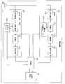
図4は、本実施形態におけるNRの下りリンクサブフレームの一例を示す図である。図4の例では、パラメータセット1、パラメータセット0およびパラメータセット2を用いて生成される信号が、セル(システム帯域幅)において、FDMされる。図4に示される図は、NRの下りリンクリソースグリッドとも呼称される。基地局装置1は、端末装置2への下りリンクサブフレームにおいて、NRの物理下りリンクチャネルおよび/またはNRの物理下りリンク信号を送信できる。端末装置2は、基地局装置1からの下りリンクサブフレームにおいて、NRの物理下りリンクチャネルおよび/またはNRの物理下りリンク信号を受信できる。
FIG. 4 is a diagram showing an example of an NR downlink subframe in this embodiment. In the example of FIG. 4, the signals generated using parameter set 1, parameter set 0 and parameter set 2 are FDMed in the cell (system bandwidth). The diagram shown in FIG. 4 is also called an NR downlink resource grid. The
図5は、本実施形態におけるNRの上りリンクサブフレームの一例を示す図である。図5の例では、パラメータセット1、パラメータセット0およびパラメータセット2を用いて生成される信号が、セル(システム帯域幅)において、FDMされる。図5に示される図は、NRの上りリンクリソースグリッドとも呼称される。基地局装置1は、端末装置2への上りリンクサブフレームにおいて、NRの物理上りリンクチャネルおよび/またはNRの物理上りリンク信号を送信できる。端末装置2は、基地局装置1からの上りリンクサブフレームにおいて、NRの物理上りリンクチャネルおよび/またはNRの物理上りリンク信号を受信できる。
FIG. 5 is a diagram showing an example of an NR uplink subframe in this embodiment. In the example of FIG. 5, signals generated using parameter set 1, parameter set 0 and parameter set 2 are FDMed in the cell (system bandwidth). The diagram shown in FIG. 5 is also called an NR uplink resource grid. The
<本実施形態における基地局装置1の構成例>
図6は、本実施形態の基地局装置1の構成を示す概略ブロック図である。図示するように、基地局装置1は、上位層処理部101、制御部103、受信部105、送信部107、および、送受信アンテナ109、を含んで構成される。また、受信部105は、復号化部1051、復調部1053、多重分離部1055、無線受信部1057、およびチャネル測定部1059を含んで構成される。また、送信部107は、符号化部1071、変調部1073、多重部1075、無線送信部1077、および下りリンク参照信号生成部1079を含んで構成される。<Configuration example of
FIG. 6 is a schematic block diagram showing the configuration of the
既に説明したように、基地局装置1は、1つ以上のRATをサポートできる。図6に示す基地局装置1に含まれる各部の一部または全部は、RATに応じて個別に構成されうる。例えば、受信部105および送信部107は、LTEとNRとで個別に構成される。また、NRセルにおいて、図6に示す基地局装置1に含まれる各部の一部または全部は、送信信号に関するパラメータセットに応じて個別に構成されうる。例えば、あるNRセルにおいて、無線受信部1057および無線送信部1077は、送信信号に関するパラメータセットに応じて個別に構成されうる。
As already explained, the
上位層処理部101は、媒体アクセス制御(MAC: Medium Access Control)層、パケットデータ統合プロトコル(Packet Data Convergence Protocol: PDCP)層、無線リンク制御(Radio Link Control: RLC)層、無線リソース制御(Radio Resource Control: RRC)層の処理を行う。また、上位層処理部101は、受信部105、および送信部107の制御を行うために制御情報を生成し、制御部103に出力する。
The upper
制御部103は、上位層処理部101からの制御情報に基づいて、受信部105および送信部107の制御を行う。制御部103は、上位層処理部101への制御情報を生成し、上位層処理部101に出力する。制御部103は、復号化部1051からの復号化された信号およびチャネル測定部1059からのチャネル推定結果を入力する。制御部103は、符号化する信号を符号化部1071へ出力する。また、制御部103は、基地局装置1の全体または一部を制御するために用いられる。
The
上位層処理部101は、RAT制御、無線リソース制御、サブフレーム設定、スケジューリング制御、および/または、CSI報告制御に関する処理および管理を行う。上位層処理部101における処理および管理は、端末装置毎、または基地局装置に接続している端末装置共通に行われる。上位層処理部101における処理および管理は、上位層処理部101のみで行われてもよいし、上位ノードまたは他の基地局装置から取得してもよい。また、上位層処理部101における処理および管理は、RATに応じて個別に行われてもよい。例えば、上位層処理部101は、LTEにおける処理および管理と、NRにおける処理および管理とを個別に行う。
Higher
上位層処理部101におけるRAT制御では、RATに関する管理が行われる。例えば、RAT制御では、LTEに関する管理および/またはNRに関する管理が行われる。NRに関する管理は、NRセルにおける送信信号に関するパラメータセットの設定および処理を含む。
In the RAT control in the upper
上位層処理部101における無線リソース制御では、下りリンクデータ(トランスポートブロック)、システムインフォメーション、RRCメッセージ(RRCパラメータ)、および/または、MAC制御エレメント(CE:Control Element)の生成および/または管理が行われる。
In the radio resource control in the upper
上位層処理部101におけるサブフレーム設定では、サブフレーム設定、サブフレームパターン設定、上りリンク-下りリンク設定、上りリンク参照UL-DL設定、および/または、下りリンク参照UL-DL設定の管理が行われる。なお、上位層処理部101におけるサブフレーム設定は、基地局サブフレーム設定とも呼称される。また、上位層処理部101におけるサブフレーム設定は、上りリンクのトラフィック量および下りリンクのトラフィック量に基づいて決定できる。また、上位層処理部101におけるサブフレーム設定は、上位層処理部101におけるスケジューリング制御のスケジューリング結果に基づいて決定できる。
In subframe setting in higher
上位層処理部101におけるスケジューリング制御では、受信したチャネル状態情報およびチャネル測定部1059から入力された伝搬路の推定値やチャネルの品質などに基づいて、物理チャネルを割り当てる周波数およびサブフレーム、物理チャネルの符号化率および変調方式および送信電力などが決定される。例えば、制御部103は、上位層処理部101におけるスケジューリング制御のスケジューリング結果に基づいて、制御情報(DCIフォーマット)を生成する。
In the scheduling control in the upper
上位層処理部101におけるCSI報告制御では、端末装置2のCSI報告が制御される。例えば、端末装置2においてCSIを算出するために想定するためのCSI参照リソースに関する設定が制御される。
In the CSI reporting control in the upper
受信部105は、制御部103からの制御に従って、送受信アンテナ109を介して端末装置2から送信された信号を受信し、さらに分離、復調、復号などの受信処理を行い、受信処理された情報を制御部103に出力する。なお、受信部105における受信処理は、あらかじめ規定された設定、または基地局装置1が端末装置2に通知した設定に基づいて行われる。
Receiving
無線受信部1057は、送受信アンテナ109を介して受信された上りリンクの信号に対して、中間周波数への変換(ダウンコンバート)、不要な周波数成分の除去、信号レベルが適切に維持されるように増幅レベルの制御、受信された信号の同相成分および直交成分に基づく直交復調、アナログ信号からディジタル信号への変換、ガードインターバル(Guard Interval: GI)の除去、および/または、高速フーリエ変換(Fast Fourier Transform: FFT)による周波数領域信号の抽出を行う。
The radio receiving unit 1057 converts the uplink signal received via the transmitting/receiving
多重分離部1055は、無線受信部1057から入力された信号から、PUCCHまたはPUSCHなどの上りリンクチャネルおよび/または上りリンク参照信号を分離する。多重分離部1055は、上りリンク参照信号をチャネル測定部1059に出力する。多重分離部1055は、チャネル測定部1059から入力された伝搬路の推定値から、上りリンクチャネルに対する伝搬路の補償を行う。
復調部1053は、上りリンクチャネルの変調シンボルに対して、BPSK(Binary Phase Shift Keying)、QPSK(Quadrature Phase shift Keying)、16QAM(Quadrature Amplitude Modulation)、64QAM、256QAM等の変調方式を用いて受信信号の復調を行う。復調部1053は、MIMO多重された上りリンクチャネルの分離および復調を行う。
復号化部1051は、復調された上りリンクチャネルの符号化ビットに対して、復号処理を行う。復号された上りリンクデータおよび/または上りリンク制御情報は制御部103へ出力される。復号化部1051は、PUSCHに対しては、トランスポートブロック毎に復号処理を行う。
The
チャネル測定部1059は、多重分離部1055から入力された上りリンク参照信号から伝搬路の推定値および/またはチャネルの品質などを測定し、多重分離部1055および/または制御部103に出力する。例えば、UL-DMRSはPUCCHまたはPUSCHに対する伝搬路補償を行うための伝搬路の推定値を測定し、SRSは上りリンクにおけるチャネルの品質を測定する。
送信部107は、制御部103からの制御に従って、上位層処理部101から入力された下りリンク制御情報および下りリンクデータに対して、符号化、変調および多重などの送信処理を行う。例えば、送信部107は、PHICH、PDCCH、EPDCCH、PDSCH、および下りリンク参照信号を生成および多重し、送信信号を生成する。なお、送信部107における送信処理は、あらかじめ規定された設定、基地局装置1が端末装置2に通知した設定、または、同一のサブフレームで送信されるPDCCHまたはEPDCCHを通じて通知される設定に基づいて行われる。
符号化部1071は、制御部103から入力されたHARQインディケータ(HARQ-ACK)、下りリンク制御情報、および下りリンクデータを、ブロック符号化、畳込み符号化、ターボ符号化等の所定の符号化方式を用いて符号化を行う。変調部1073は、符号化部1071から入力された符号化ビットをBPSK、QPSK、16QAM、64QAM、256QAM等の所定の変調方式で変調する。下りリンク参照信号生成部1079は、物理セル識別子(PCI:Physical cell identification)、端末装置2に設定されたRRCパラメータなどに基づいて、下りリンク参照信号を生成する。多重部1075は、各チャネルの変調シンボルと下りリンク参照信号を多重し、所定のリソースエレメントに配置する。
無線送信部1077は、多重部1075からの信号に対して、逆高速フーリエ変換(Inverse Fast Fourier Transform: IFFT)による時間領域の信号への変換、ガードインターバルの付加、ベースバンドのディジタル信号の生成、アナログ信号への変換、直交変調、中間周波数の信号から高周波数の信号への変換(アップコンバート: up convert)、余分な周波数成分の除去、電力の増幅などの処理を行い、送信信号を生成する。無線送信部1077が出力した送信信号は、送受信アンテナ109から送信される。
The
<本実施形態における端末装置2の構成例>
図7は、本実施形態の端末装置2の構成を示す概略ブロック図である。図示するように、端末装置2は、上位層処理部201、制御部203、受信部205、送信部207、および送受信アンテナ209を含んで構成される。また、受信部205は、復号化部2051、復調部2053、多重分離部2055、無線受信部2057、およびチャネル測定部2059を含んで構成される。また、送信部207は、符号化部2071、変調部2073、多重部2075、無線送信部2077、および上りリンク参照信号生成部2079を含んで構成される。<Configuration example of the
FIG. 7 is a schematic block diagram showing the configuration of the
既に説明したように、端末装置2は、1つ以上のRATをサポートできる。図7に示す端末装置2に含まれる各部の一部または全部は、RATに応じて個別に構成されうる。例えば、受信部205および送信部207は、LTEとNRとで個別に構成される。また、NRセルにおいて、図7に示す端末装置2に含まれる各部の一部または全部は、送信信号に関するパラメータセットに応じて個別に構成されうる。例えば、あるNRセルにおいて、無線受信部2057および無線送信部2077は、送信信号に関するパラメータセットに応じて個別に構成されうる。
As already explained, the
上位層処理部201は、上りリンクデータ(トランスポートブロック)を、制御部203に出力する。上位層処理部201は、媒体アクセス制御(MAC: Medium Access Control)層、パケットデータ統合プロトコル(Packet Data Convergence Protocol: PDCP)層、無線リンク制御(Radio Link Control: RLC)層、無線リソース制御(Radio Resource Control: RRC)層の処理を行なう。また、上位層処理部201は、受信部205、および送信部207の制御を行うために制御情報を生成し、制御部203に出力する。
The upper
制御部203は、上位層処理部201からの制御情報に基づいて、受信部205および送信部207の制御を行う。制御部203は、上位層処理部201への制御情報を生成し、上位層処理部201に出力する。制御部203は、復号化部2051からの復号化された信号およびチャネル測定部2059からのチャネル推定結果を入力する。制御部203は、符号化する信号を符号化部2071へ出力する。また、制御部203は、端末装置2の全体または一部を制御するために用いられてもよい。
The
上位層処理部201は、RAT制御、無線リソース制御、サブフレーム設定、スケジューリング制御、および/または、CSI報告制御に関する処理および管理を行う。上位層処理部201における処理および管理は、あらかじめ規定される設定、および/または、基地局装置1から設定または通知される制御情報に基づく設定に基づいて行われる。例えば、基地局装置1からの制御情報は、RRCパラメータ、MAC制御エレメントまたはDCIを含む。また、上位層処理部201における処理および管理は、RATに応じて個別に行われてもよい。例えば、上位層処理部201は、LTEにおける処理および管理と、NRにおける処理および管理とを個別に行う。
Higher
上位層処理部201におけるRAT制御では、RATに関する管理が行われる。例えば、RAT制御では、LTEに関する管理および/またはNRに関する管理が行われる。NRに関する管理は、NRセルにおける送信信号に関するパラメータセットの設定および処理を含む。
In the RAT control in the upper
上位層処理部201における無線リソース制御では、自装置における設定情報の管理が行われる。上位層処理部201における無線リソース制御では、上りリンクデータ(トランスポートブロック)、システムインフォメーション、RRCメッセージ(RRCパラメータ)、および/または、MAC制御エレメント(CE:Control Element)の生成および/または管理が行われる。
In radio resource control in the upper
上位層処理部201におけるサブフレーム設定では、基地局装置1および/または基地局装置1とは異なる基地局装置におけるサブフレーム設定が管理される。サブフレーム設定は、サブフレームに対する上りリンクまたは下りリンクの設定、サブフレームパターン設定、上りリンク-下りリンク設定、上りリンク参照UL-DL設定、および/または、下りリンク参照UL-DL設定を含む。なお、上位層処理部201におけるサブフレーム設定は、端末サブフレーム設定とも呼称される。
Subframe settings in higher
上位層処理部201におけるスケジューリング制御では、基地局装置1からのDCI(スケジューリング情報)に基づいて、受信部205および送信部207に対するスケジューリングに関する制御を行うための制御情報が生成される。
In scheduling control in upper
上位層処理部201におけるCSI報告制御では、基地局装置1に対するCSIの報告に関する制御が行われる。例えば、CSI報告制御では、チャネル測定部2059でCSIを算出するために想定するためのCSI参照リソースに関する設定が制御される。CSI報告制御では、DCIおよび/またはRRCパラメータに基づいて、CSIを報告するために用いられるリソース(タイミング)を制御する。
In CSI reporting control in higher
受信部205は、制御部203からの制御に従って、送受信アンテナ209を介して基地局装置1から送信された信号を受信し、さらに分離、復調、復号などの受信処理を行い、受信処理された情報を制御部203に出力する。なお、受信部205における受信処理は、あらかじめ規定された設定、または基地局装置1からの通知または設定に基づいて行われる。
Receiving
無線受信部2057は、送受信アンテナ209を介して受信された上りリンクの信号に対して、中間周波数への変換(ダウンコンバート)、不要な周波数成分の除去、信号レベルが適切に維持されるように増幅レベルの制御、受信された信号の同相成分および直交成分に基づく直交復調、アナログ信号からディジタル信号への変換、ガードインターバル(Guard Interval: GI)の除去、および/または、高速フーリエ変換(Fast Fourier Transform: FFT)による周波数領域の信号の抽出を行う。
The radio reception unit 2057 converts the uplink signal received via the transmission/
多重分離部2055は、無線受信部2057から入力された信号から、PHICH、PDCCH、EPDCCHまたはPDSCHなどの下りリンクチャネル、下りリンク同期信号および/または下りリンク参照信号を分離する。多重分離部2055は、下りリンク参照信号をチャネル測定部2059に出力する。多重分離部2055は、チャネル測定部2059から入力された伝搬路の推定値から、下りリンクチャネルに対する伝搬路の補償を行う。
復調部2053は、下りリンクチャネルの変調シンボルに対して、BPSK、QPSK、16QAM、64QAM、256QAM等の変調方式を用いて受信信号の復調を行う。復調部2053は、MIMO多重された下りリンクチャネルの分離および復調を行う。
The
復号化部2051は、復調された下りリンクチャネルの符号化ビットに対して、復号処理を行う。復号された下りリンクデータおよび/または下りリンク制御情報は制御部203へ出力される。復号化部2051は、PDSCHに対しては、トランスポートブロック毎に復号処理を行う。
The
チャネル測定部2059は、多重分離部2055から入力された下りリンク参照信号から伝搬路の推定値および/またはチャネルの品質などを測定し、多重分離部2055および/または制御部203に出力する。チャネル測定部2059が測定に用いる下りリンク参照信号は、少なくともRRCパラメータによって設定される送信モードおよび/または他のRRCパラメータに基づいて決定されてもよい。例えば、DL-DMRSはPDSCHまたはEPDCCHに対する伝搬路補償を行うための伝搬路の推定値を測定する。CRSはPDCCHまたはPDSCHに対する伝搬路補償を行うための伝搬路の推定値、および/または、CSIを報告するための下りリンクにおけるチャネルを測定する。CSI-RSは、CSIを報告するための下りリンクにおけるチャネルを測定する。チャネル測定部2059は、CRS、CSI-RSまたは検出信号に基づいて、RSRP(Reference Signal Received Power)および/またはRSRQ(Reference Signal Received Quality)を算出し、上位層処理部201へ出力する。
送信部207は、制御部203からの制御に従って、上位層処理部201から入力された上りリンク制御情報および上りリンクデータに対して、符号化、変調および多重などの送信処理を行う。例えば、送信部207は、PUSCHまたはPUCCHなどの上りリンクチャネルおよび/または上りリンク参照信号を生成および多重し、送信信号を生成する。なお、送信部207における送信処理は、あらかじめ規定された設定、または、基地局装置1から設定または通知に基づいて行われる。
The
符号化部2071は、制御部203から入力されたHARQインディケータ(HARQ-ACK)、上りリンク制御情報、および上りリンクデータを、ブロック符号化、畳込み符号化、ターボ符号化等の所定の符号化方式を用いて符号化を行う。変調部2073は、符号化部2071から入力された符号化ビットをBPSK、QPSK、16QAM、64QAM、256QAM等の所定の変調方式で変調する。上りリンク参照信号生成部2079は、端末装置2に設定されたRRCパラメータなどに基づいて、上りリンク参照信号を生成する。多重部2075は、各チャネルの変調シンボルと上りリンク参照信号を多重し、所定のリソースエレメントに配置する。
無線送信部2077は、多重部2075からの信号に対して、逆高速フーリエ変換(Inverse Fast Fourier Transform: IFFT)による時間領域の信号への変換、ガードインターバルの付加、ベースバンドのディジタル信号の生成、アナログ信号への変換、直交変調、中間周波数の信号から高周波数の信号への変換(アップコンバート: up convert)、余分な周波数成分の除去、電力の増幅などの処理を行い、送信信号を生成する。無線送信部2077が出力した送信信号は、送受信アンテナ209から送信される。
The
<本実施形態における制御情報のシグナリング>
基地局装置1および端末装置2は、それぞれ制御情報のシグナリング(通知、報知、設定)のために、様々な方法を用いることができる。制御情報のシグナリングは、様々な層(レイヤー)で行うことができる。制御情報のシグナリングは、物理層(レイヤー)を通じたシグナリングである物理層シグナリング、RRC層を通じたシグナリングであるRRCシグナリング、および、MAC層を通じたシグナリングであるMACシグナリングなどを含む。RRCシグナリングは、端末装置2に固有の制御情報を通知する専用のRRCシグナリング(Dedicated RRC signaling)、または、基地局装置1に固有の制御情報を通知する共通のRRCシグナリング(Common RRC signaling)である。RRCシグナリングやMACシグナリングなど、物理層から見て上位の層が用いるシグナリングは上位層シグナリングとも呼称される。<Signaling of control information in this embodiment>
The
RRCシグナリングは、RRCパラメータをシグナリングすることにより実現される。MACシグナリングは、MAC制御エレメントをシグナリングすることにより実現される。物理層シグナリングは、下りリンク制御情報(DCI:Downlink Control Information)または上りリンクリンク制御情報(UCI:Uplink Control Information)をシグナリングすることにより実現される。RRCパラメータおよびMAC制御エレメントは、PDSCHまたはPUSCHを用いて送信される。DCIは、PDCCHまたはEPDCCHを用いて送信される。UCIは、PUCCHまたはPUSCHを用いて送信される。RRCシグナリングおよびMACシグナリングは、準静的(semi-static)な制御情報をシグナリングするために用いられ、準静的シグナリングとも呼称される。物理層シグナリングは、動的(dynamic)な制御情報をシグナリングするために用いられ、動的シグナリングとも呼称される。DCIは、PDSCHのスケジューリングまたはPUSCHのスケジューリングなどのために用いられる。UCIは、CSI報告、HARQ-ACK報告、および/またはスケジューリング要求(SR:Scheduling Request)などのために用いられる。 RRC signaling is achieved by signaling RRC parameters. MAC signaling is achieved by signaling MAC control elements. Physical layer signaling is achieved by signaling Downlink Control Information (DCI) or Uplink Control Information (UCI). RRC parameters and MAC control elements are transmitted using PDSCH or PUSCH. DCI is transmitted using PDCCH or EPDCCH. UCI is transmitted using PUCCH or PUSCH. RRC signaling and MAC signaling are used to signal semi-static control information and are also referred to as semi-static signaling. Physical layer signaling is used to signal dynamic control information and is also called dynamic signaling. The DCI is used for PDSCH scheduling, PUSCH scheduling, or the like. UCI is used for CSI reporting, HARQ-ACK reporting, and/or Scheduling Request (SR), and the like.
<本実施形態における下りリンク制御情報の詳細>
DCIはあらかじめ規定されるフィールドを有するDCIフォーマットを用いて通知される。DCIフォーマットに規定されるフィールドは、所定の情報ビットがマッピングされる。DCIは、下りリンクスケジューリング情報、上りリンクスケジューリング情報、サイドリンクスケジューリング情報、非周期的CSI報告の要求、または、上りリンク送信電力コマンドを通知する。<Details of downlink control information in this embodiment>
DCI is signaled using a DCI format with predefined fields. Predetermined information bits are mapped to fields defined in the DCI format. DCI notifies downlink scheduling information, uplink scheduling information, sidelink scheduling information, aperiodic CSI report request, or uplink transmission power command.
端末装置2がモニタするDCIフォーマットは、サービングセル毎に設定された送信モードによって決まる。すなわち、端末装置2がモニタするDCIフォーマットの一部は、送信モードによって異なることができる。例えば、下りリンク送信モード1が設定された端末装置2は、DCIフォーマット1AとDCIフォーマット1をモニタする。例えば、下りリンク送信モード4が設定された端末装置2は、DCIフォーマット1AとDCIフォーマット2をモニタする。例えば、上りリンク送信モード1が設定された端末装置2は、DCIフォーマット0をモニタする。例えば、上りリンク送信モード2が設定された端末装置2は、DCIフォーマット0とDCIフォーマット4をモニタする。
The DCI format monitored by the
端末装置2に対するDCIを通知するPDCCHが配置される制御領域は通知されず、端末装置2は端末装置2に対するDCIをブラインドデコーディング(ブラインド検出)により検出する。具体的には、端末装置2は、サービングセルにおいて、PDCCH候補のセットをモニタする。モニタリングは、そのセットの中のPDCCHのそれぞれに対して、全てのモニタされるDCIフォーマットによって復号を試みることを意味する。例えば、端末装置2は、端末装置2宛に送信される可能性がある全てのアグリゲーションレベル、PDCCH候補、および、DCIフォーマットについてデコードを試みる。端末装置2は、デコード(検出)が成功したDCI(PDCCH)を端末装置2に対するDCI(PDCCH)として認識する。
The control region in which the PDCCH that notifies the DCI for the
DCIに対して、巡回冗長検査(CRC: Cyclic Redundancy Check)が付加される。CRCは、DCIのエラー検出およびDCIのブラインド検出のために用いられる。CRC(CRCパリティビット)は、RNTI(Radio Network Temporary Identifier)によってスクランブルされる。端末装置2は、RNTIに基づいて、端末装置2に対するDCIかどうかを検出する。具体的には、端末装置2は、CRCに対応するビットに対して、所定のRNTIでデスクランブルを行い、CRCを抽出し、対応するDCIが正しいかどうかを検出する。
A cyclic redundancy check (CRC) is added to the DCI. The CRC is used for DCI error detection and DCI blind detection. CRC (CRC parity bits) is scrambled by RNTI (Radio Network Temporary Identifier). The
RNTIは、DCIの目的や用途に応じて規定または設定される。RNTIは、C-RNTI(Cell-RNTI)、SPS C-RNTI(Semi Persistent Scheduling C-RNTI)、SI-RNTI(System Information-RNTI)、P-RNTI(Paging-RNTI)、RA-RNTI(Random Access-RNTI)、TPC-PUCCH-RNTI(Transmit Power Control-PUCCH-RNTI)、TPC-PUSCH-RNTI(Transmit Power Control-PUSCH-RNTI)、一時的C-RNTI、M-RNTI(MBMS (Multimedia Broadcast Muticast Services) -RNTI)、および、eIMTA-RNTIを含む。 RNTI is defined or set according to the purpose and use of DCI. RNTI includes C-RNTI (Cell-RNTI), SPS C-RNTI (Semi Persistent Scheduling C-RNTI), SI-RNTI (System Information-RNTI), P-RNTI (Paging-RNTI), RA-RNTI (Random Access -RNTI), TPC-PUCCH-RNTI (Transmit Power Control-PUCCH-RNTI), TPC-PUSCH-RNTI (Transmit Power Control-PUSCH-RNTI), Temporary C-RNTI, M-RNTI (MBMS (Multimedia Broadcast Muticast Services )-RNTI), and eIMTA-RNTI.
C-RNTIおよびSPS C-RNTIは、基地局装置1(セル)内において端末装置2に固有のRNTIであり、端末装置2を識別するための識別子である。C-RNTIは、あるサブフレームにおけるPDSCHまたはPUSCHをスケジューリングするために用いられる。SPS C-RNTIは、PDSCHまたはPUSCHのためのリソースの周期的なスケジューリングをアクティベーションまたはリリースするために用いられる。SI-RNTIでスクランブルされたCRCを有する制御チャネルは、SIB(System Information Block)をスケジューリングするために用いられる。P-RNTIでスクランブルされたCRCを有する制御チャネルは、ページングを制御するために用いられる。RA-RNTIでスクランブルされたCRCを有する制御チャネルは、RACHに対するレスポンスをスケジューリングするために用いられる。TPC-PUCCH-RNTIでスクランブルされたCRCを有する制御チャネルは、PUCCHの電力制御を行うために用いられる。TPC-PUSCH-RNTIでスクランブルされたCRCを有する制御チャネルは、PUSCHの電力制御を行うために用いられる。Temporary C-RNTIでスクランブルされたCRCを有する制御チャネルは、C-RNTIが設定または認識されていない移動局装置によって用いられる。M-RNTIでスクランブルされたCRCを有する制御チャネルは、MBMSをスケジューリングするために用いられる。eIMTA-RNTIでスクランブルされたCRCを有する制御チャネルは、動的TDD(eIMTA)において、TDDサービングセルのTDD UL/DL設定に関する情報を通知するために用いられる。なお、上記のRNTIに限らず、新たなRNTIによってDCIフォーマットがスクランブルされてもよい。
The C-RNTI and SPS C-RNTI are RNTIs unique to the
スケジューリング情報(下りリンクスケジューリング情報、上りリンクスケジューリング情報、サイドリンクスケジューリング情報)は、周波数領域のスケジューリングとして、リソースブロックまたはリソースブロックグループを単位にスケジューリングを行うための情報を含む。リソースブロックグループは、連続するリソースブロックのセットであり、スケジューリングされる端末装置に対する割り当てられるリソースを示す。リソースブロックグループのサイズは、システム帯域幅に応じて決まる。 Scheduling information (downlink scheduling information, uplink scheduling information, sidelink scheduling information) includes information for performing scheduling in units of resource blocks or resource block groups as scheduling in the frequency domain. A resource block group is a set of contiguous resource blocks and indicates allocated resources for a scheduled terminal device. The size of the resource block group depends on the system bandwidth.
<本実施形態における下りリンク制御チャネルの詳細>
DCIはPDCCHまたはEPDCCHなどの制御チャネルを用いて送信される。端末装置2は、RRCシグナリングによって設定された1つまたは複数のアクティベートされたサービングセルのPDCCH候補のセットおよび/またはEPDCCH候補のセットをモニタする。ここで、モニタリングとは、全てのモニタされるDCIフォーマットに対応するセット内のPDCCHおよび/またはEPDCCHのデコードを試みることである。<Details of downlink control channel in this embodiment>
DCI is transmitted using a control channel such as PDCCH or EPDCCH. The
PDCCH候補のセットまたはEPDCCH候補のセットは、サーチスペースとも呼称される。サーチスペースには、共有サーチスペース(CSS)と端末固有サーチスペース(USS)が定義される。CSSは、PDCCHに関するサーチスペースのみに対して定義されてもよい。 A set of PDCCH candidates or a set of EPDCCH candidates is also referred to as a search space. A shared search space (CSS) and a terminal-specific search space (USS) are defined as search spaces. CSS may be defined only for the search space for PDCCH.
CSS(Common Search Space)は、基地局装置1に固有のパラメータおよび/または予め規定されたパラメータに基づいて設定されるサーチスペースである。例えば、CSSは、複数の端末装置で共通に用いられるサーチスペースである。そのため、基地局装置1が複数の端末装置で共通の制御チャネルをCSSにマッピングすることにより、制御チャネルを送信するためのリソースが低減される。
A CSS (Common Search Space) is a search space that is set based on parameters specific to the
USS(UE-specific Search Space)は、少なくとも端末装置2に固有のパラメータを用いて設定されるサーチスペースである。そのため、USSは、端末装置2に固有のサーチスペースであり、端末装置2に固有の制御チャネルを個別に送信することができる。そのため、基地局装置1は複数の端末装置に固有の制御チャネルを効率的にマッピングできる。
A USS (UE-specific Search Space) is a search space that is set using at least parameters specific to the
USSは、複数の端末装置に共通に用いられるように設定されてもよい。複数の端末装置に対して共通のUSSが設定されるために、端末装置2に固有のパラメータは、複数の端末装置の間で同じ値になるように設定される。例えば、複数の端末装置の間で同じパラメータに設定される単位は、セル、送信点、または所定の端末装置のグループなどである。
A USS may be set to be commonly used by a plurality of terminal devices. Since a common USS is set for a plurality of terminal devices, parameters unique to the
アグリゲーションレベル毎のサーチスペースはPDCCH候補のセットによって定義される。PDCCHのそれぞれは、1つ以上のCCE(Control Channel Element)の集合を用いて送信される。1つのPDCCHに用いられるCCEの数は、アグリゲーションレベルとも呼称される。例えば、1つのPDCCHに用いられるCCEの数は、1、2、4または8である。 The search space for each aggregation level is defined by the set of PDCCH candidates. Each PDCCH is transmitted using a set of one or more CCEs (Control Channel Elements). The number of CCEs used for one PDCCH is also called an aggregation level. For example, the number of CCEs used for one PDCCH is 1, 2, 4 or 8.
アグリゲーションレベル毎のサーチスペースはEPDCCH候補のセットによって定義される。EPDCCHのそれぞれは、1つ以上のECCE(Enhanced Control Channel Element)の集合を用いて送信される。1つのEPDCCHに用いられるECCEの数は、アグリゲーションレベルとも呼称される。例えば、1つのEPDCCHに用いられるECCEの数は、1、2、4、8、16または32である。 A search space for each aggregation level is defined by the set of EPDCCH candidates. Each EPDCCH is transmitted using a set of one or more ECCEs (Enhanced Control Channel Elements). The number of ECCEs used for one EPDCCH is also called an aggregation level. For example, the number of ECCEs used for one EPDCCH is 1, 2, 4, 8, 16 or 32.
PDCCH候補の数またはEPDCCH候補の数は、少なくともサーチスペースおよびアグリゲーションレベルに基づいて決まる。例えば、CSSにおいて、アグリゲーションレベル4および8におけるPDCCH候補の数はそれぞれ4および2である。例えば、USSにおいて、アグリゲーション1、2、4および8におけるPDCCH候補の数はそれぞれ6、6、2および2である。
The number of PDCCH candidates or the number of EPDCCH candidates is determined based on at least the search space and the aggregation level. For example, in CSS, the number of PDCCH candidates at
それぞれのECCEは、複数のEREG(Enhanced resource element group)で構成される。EREGは、EPDCCHのリソースエレメントに対するマッピングを定義するために用いられる。各RBペアにおいて、0から15に番号付けされる、16個のEREGが定義される。すなわち、各RBペアにおいて、EREG0~EREG15が定義される。各RBペアにおいて、EREG0~EREG15は、所定の信号および/またはチャネルがマッピングされるリソースエレメント以外のリソースエレメントに対して、周波数方向を優先して、周期的に定義される。例えば、アンテナポート107~110で送信されるEPDCCHに関連付けられる復調用参照信号がマッピングされるリソースエレメントは、EREGを定義しない。 Each ECCE is composed of a plurality of EREGs (Enhanced resource element groups). The EREG is used to define the mapping to EPDCCH resource elements. Sixteen EREGs, numbered from 0 to 15, are defined in each RB pair. That is, EREG0 to EREG15 are defined for each RB pair. In each RB pair, EREG0 to EREG15 are periodically defined with priority in the frequency direction for resource elements other than resource elements to which predetermined signals and/or channels are mapped. For example, resource elements to which demodulation reference signals associated with EPDCCHs transmitted on antenna ports 107-110 are mapped do not define EREG.
1つのEPDCCHに用いられるECCEの数は、EPDCCHフォーマットに依存し、他のパラメータに基づいて決定される。1つのEPDCCHに用いられるECCEの数は、アグリゲーションレベルとも呼称される。例えば、1つのEPDCCHに用いられるECCEの数は、1つのRBペアにおけるEPDCCH送信に用いることができるリソースエレメントの数、EPDCCHの送信方法などに基づいて、決定される。例えば、1つのEPDCCHに用いられるECCEの数は、1、2、4、8、16または32である。また、1つのECCEに用いられるEREGの数は、サブフレームの種類およびサイクリックプレフィックスの種類に基づいて決定され、4または8である。EPDCCHの送信方法として、分散送信(Distributed transmission)および局所送信(Localized transmission)がサポートされる。 The number of ECCEs used for one EPDCCH depends on the EPDCCH format and is determined based on other parameters. The number of ECCEs used for one EPDCCH is also called an aggregation level. For example, the number of ECCEs used for one EPDCCH is determined based on the number of resource elements that can be used for EPDCCH transmission in one RB pair, the EPDCCH transmission method, and the like. For example, the number of ECCEs used for one EPDCCH is 1, 2, 4, 8, 16 or 32. Also, the number of EREGs used for one ECCE is 4 or 8, which is determined based on the type of subframe and the type of cyclic prefix. Distributed transmission and localized transmission are supported as EPDCCH transmission methods.
EPDCCHは、分散送信または局所送信を用いることができる。分散送信および局所送信は、EREGおよびRBペアに対するECCEのマッピングが異なる。例えば、分散送信において、1つのECCEは、複数のRBペアのEREGを用いて構成される。局所送信において、1つのECCEは、1つのRBペアのEREGを用いて構成される。 EPDCCH can use distributed or localized transmission. Distributed and localized transmission differ in the mapping of ECCE to EREG and RB pairs. For example, in distributed transmission, one ECCE is configured using EREGs of multiple RB pairs. In local transmission, one ECCE is constructed using one RB pair EREG.
基地局装置1は、端末装置2に対して、EPDCCHに関する設定を行う。端末装置2は、基地局装置1からの設定に基づいて、複数のEPDCCHをモニタリングする。端末装置2がEPDCCHをモニタリングするRBペアのセットが、設定されうる。そのRBペアのセットは、EPDCCHセットまたはEPDCCH-PRBセットとも呼称される。1つの端末装置2に対して、1つ以上のEPDCCHセットが設定できる。各EPDCCHセットは、1つ以上のRBペアで構成される。また、EPDCCHに関する設定は、EPDCCHセット毎に個別に行うことができる。
The
基地局装置1は、端末装置2に対して、所定数のEPDCCHセットを設定できる。例えば、2つまでのEPDCCHセットが、EPDCCHセット0および/またはEPDCCHセット1として、設定できる。EPDCCHセットのそれぞれは、所定数のRBペアで構成できる。各EPDCCHセットは、複数のECCEの1つのセットを構成する。1つのEPDCCHセットに構成されるECCEの数は、そのEPDCCHセットとして設定されるRBペアの数、および、1つのECCEに用いられるEREGの数に基づいて、決定される。1つのEPDCCHセットに構成されるECCEの数がNである場合、各EPDCCHセットは、0~N-1で番号付けされたECCEを構成する。例えば、1つのECCEに用いられるEREGの数が4である場合、4つのRBペアで構成されるEPDCCHセットは16個のECCEを構成する。
The
<Non-Orthogonal Multiple Access(NOMA)>
直交多元接続(Orthogonal Multiple Access:OMA)送信においては、例えば直交する周波数軸および時間軸を用いて送受信を行う。この時、サブキャリア間隔によって周波数および時間リソースのフレーム構成が決定され、リソースエレメント数以上のリソースを使用することは困難である。一方、NOMA送信においては、直交する周波数軸および時間軸に加えて、非直交軸を追加してフレーム構成が決定される。なお、非直交軸の一例として、Interleave pattern軸、Spreading Pattern軸、Scrambling Pattern軸、Codebook軸、Power軸などが挙げられる。<Non-Orthogonal Multiple Access (NOMA)>
In orthogonal multiple access (OMA) transmission, for example, transmission and reception are performed using orthogonal frequency and time axes. At this time, the subcarrier spacing determines the frame configuration of frequency and time resources, and it is difficult to use resources that exceed the number of resource elements. On the other hand, in NOMA transmission, the frame configuration is determined by adding a non-orthogonal axis in addition to the orthogonal frequency axis and time axis. Examples of non-orthogonal axes include an interleave pattern axis, a spreading pattern axis, a scrambling pattern axis, a codebook axis, and a power axis.
例えば、図8は、NOMA送信の一例について概要を説明するための説明図であり、送信装置において非直交軸で送信信号を多重し、かつ非直交軸で多重されるリソースが全て同一のパラメータセットの場合を表している。ここで、送信装置は基地局装置1または端末装置2のいずれかを示す。送信装置では、多重をする複数の送信信号セットを用意する。図8では2つの送信信号セットを多重するとする。ここでは2つとしているが3つ以上の送信信号セットでもよい。また、それぞれの送信信号セットは別々の受信装置に対する送信信号でもよいし、同一の受信装置に対する送信信号でもよい。ここで、受信装置は基地局装置1または端末装置2のいずれかを示す。それぞれの送信信号セットは、対応するMultiple Access(MA) signatureが適用される。ここで、MA signatureには、例えば、Interleave pattern、Spreading Pattern、Scrambling Pattern、Codebook、Power Allocation、Repetitionなどが含まれる。また、ここではMA signatureと呼称したが、単にPatternやIndexといった呼称でもよく、例として上記に挙げたようなNOMA送信で使用されるPatternやIndexといった識別子や、Patternそのものを表すものを指す。MA signature適用後の信号は同一の周波数および時間リソース上で多重され、同一のアンテナポートへ送られる。
For example, FIG. 8 is an explanatory diagram for explaining an outline of an example of NOMA transmission. represents the case of Here, the transmitting device indicates either the
また、図8では同一のパラメータセットの送信信号セットを多重したが、図9に示すように、異なるパラメータセットの送信信号セットを多重してもよい。図9は、NOMA送信の他の一例について概要を説明するための説明図であり、異なるパラメータセットの送信信号セットを多重している以外は、図8と同様である。 Also, although transmission signal sets of the same parameter set are multiplexed in FIG. 8, transmission signal sets of different parameter sets may be multiplexed as shown in FIG. FIG. 9 is an explanatory diagram for explaining an outline of another example of NOMA transmission, which is the same as FIG. 8 except that transmission signal sets with different parameter sets are multiplexed.
一方で、図10及び図11に示すように、送信装置で多重せず、MA signatureを適用した信号を送信し、受信装置で非直交多重されるように送信をする方法も考えられる。図10及び図11は、NOMA送信の他の一例について概要を説明するための説明図であり、送信装置による多重が行われない場合の一例を示している。図10及び図11に示す例では、それぞれの送信信号セットは、対応するMA signatureが適用される。ここで、MA signatureには、例えば、Interleave pattern、Spreading Pattern、Scrambling Pattern、Codebook、Power Allocation、Repetitionなどが含まれる。MA signature適用後の信号は同一の周波数および時間リソース上で送信され、伝搬チャネルを通って多重される。この場合、それぞれの送信信号セットは別々の送信装置から送信されてもよい。また、図11に示したように、同一の周波数および時間リソース上で送信される送信信号のパラメータセットは、異なるパラメータセットでもよい。 On the other hand, as shown in FIGS. 10 and 11, a method of transmitting a signal to which the MA signature is applied without multiplexing in the transmitting apparatus and transmitting the signal so as to be non-orthogonal multiplexed in the receiving apparatus is also conceivable. 10 and 11 are explanatory diagrams for explaining the outline of another example of NOMA transmission, and show an example in which multiplexing is not performed by the transmission device. In the examples shown in FIGS. 10 and 11, each transmitted signal set has a corresponding MA signature applied. Here, the MA signature includes, for example, Interleave pattern, Spreading Pattern, Scrambling Pattern, Codebook, Power Allocation, Repetition, and the like. Signals after applying the MA signature are transmitted on the same frequency and time resources and multiplexed through the propagation channel. In this case, each transmit signal set may be transmitted from a separate transmitter. Also, as shown in FIG. 11, the parameter sets of transmission signals transmitted on the same frequency and time resources may be different parameter sets.
図12は、NOMA送信の一例について概要を説明するための説明図であり、受信装置の一例を示している。図12に示すように、受信信号は同一の周波数および時間リソース上で複数の送信信号が多重された状態で受信される。受信装置では多重された送信信号セットを復号するため、送信機で適用されたMA signatureを適用し、チャネル等化および干渉信号キャンセラにより所望の信号が取り出される。この時、同一のMA signatureが用いられて多重された場合には、多重された信号間の干渉の影響が大きくなり、復号をすることが困難となる場合がある。 FIG. 12 is an explanatory diagram for explaining an outline of an example of NOMA transmission, and shows an example of a receiving device. As shown in FIG. 12, received signals are received in a state in which a plurality of transmitted signals are multiplexed on the same frequency and time resources. In order to decode the multiplexed transmission signal set, the receiver applies the MA signature applied by the transmitter, and extracts the desired signal by channel equalization and interference signal canceller. At this time, if the same MA signature is used for multiplexing, the influence of interference between the multiplexed signals increases, and decoding may become difficult.
以上のように、NOMA送信では、送信装置および受信装置で適用されたMA signatureを送信装置および受信装置間で共有し、かつ、MA signatureが重複することなく適用される必要がある。また、以降の議論でリソースと言った場合には、MA signatureもリソースの一つとして含むこととする。ここで、周波数・時間・MA signatureすべてを含むリソースをMultiple Access(MA)リソースと呼ぶ場合もあり、周波数・時間のみのリソースをMultiple Access(MA) Physicalリソースと呼ぶ場合もある。 As described above, in NOMA transmission, it is necessary to share the MA signatures applied by the transmitting device and the receiving device between the transmitting device and the receiving device, and to apply the MA signatures without duplication. In addition, when referring to a resource in the following discussion, the MA signature is also included as one of the resources. Here, a resource including all of frequency, time, and MA signature may be called Multiple Access (MA) resource, and a resource of only frequency and time may be called Multiple Access (MA) Physical resource.
<Grant-free送信>
Grant-free送信とは、端末装置2が基地局装置1からの動的なリソースアロケーション(Grant)を受信することなく、あらかじめ基地局装置1から指示された使用可能な周波数および時間リソースから、端末装置2が適当なリソースを利用して送信をすることを表す。すなわち、Grant-free送信は、Downlink Control Information(DCI)に、Grantを含まずに、データ送信を実施するものを表す。Grant-free送信はData transmission without grantなどとも呼ばれるが、以降の説明では便宜上、Grant-free送信と呼ぶこととする。Grant-free送信においては、基地局装置1は、端末装置2が選択可能な周波数および時間リソースの候補を事前に指定しても良い。<Grant-free transmission>
Grant-free transmission means that the
Grant-free送信を適用する主な目的として、シグナリングオーバーヘッドの削減による、端末装置2の省電力化や低遅延通信がある。従来の方式では、基地局装置1が端末装置2に対して、UplinkやSidelinkで使用するリソースを通知することで、他の端末装置2とのリソース競合が発生せずに通信を行うことが可能となっていた。一方で、従来の方式においては、本通知によるシグナリングのオーバーヘッドが発生する場合がある。
The main purpose of applying grant-free transmission is power saving of the
例えば、図13は、Grant based送信について概要を説明するための説明図である。図13に示すようなGrant based送信の場合には、端末装置2は、データが発生すると(S11)、基地局装置1にリソース割り当て要求を送信する(S12)。基地局装置1は、端末装置2からのリソース割り当て要求を受けて、当該端末装置2に対してリソースを割り当てる(S13)。次いで、端末装置2は、基地局装置1から割り当てられたリソースを用いて、データを送信する(S14)。基地局装置1は、端末装置2から送信されたデータを受信すると、当該端末装置2に対して応答(例えば、ACK/NACK)を送信する(S15)。このような構成のため、Grant based送信においては、端末装置2からのリソースの割り当て要求や、基地局装置1によるリソースの割り当てに伴うシグナリングオーバーヘッドが生じる。
For example, FIG. 13 is an explanatory diagram for explaining an outline of Grant based transmission. In the case of Grant based transmission as shown in FIG. 13, when data is generated (S11), the
これに対して、図14は、Grant-free送信について概要を説明するための説明図である。図14に示すようなGrant-free送信の場合には、基地局装置1から端末装置2に対して使用可能なリソースがあらかじめ割り当てられる(S21)。端末装置2は、データが発生すると(S22)、事前に割り当てられたリソースの中から任意に選択したリソースを使用して当該データを基地局装置1に送信する(S23)。基地局装置1は、端末装置2から送信されたデータを受信すると、当該端末装置2に対して応答(例えば、ACK/NACK)を送信する(S24)。上述の通り、Grant-free送信の場合には、図13に示すGrant based送信における、端末装置2からのリソースの割り当て要求や、基地局装置1によるリソースの割り当てに係る処理が削減される。そのため、次世代の通信で求められる省電力化や低遅延通信において、リソース割り当て通知を行わないGrant-free送信は有力な技術候補として期待されている。なお、Grant-free 送信における送信リソースは、使用可能な全帯域から選択されても良いし、あらかじめ基地局装置1から指定されたリソースの中から選択されても良い。
On the other hand, FIG. 14 is an explanatory diagram for explaining an outline of Grant-free transmission. In the case of grant-free transmission as shown in FIG. 14, usable resources are allocated in advance from the
<Code Block Group(CBG)>
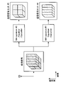
CBGとは、一つまたは複数のCode Block(CB)をいくつかのGroupにまとめたものを指す。例えば、図15のように、一つのTransport Block(TB)に8個のCBが含まれていると仮定する。CBGは、これらのCBを一つまたは複数のGroupに分けたものを指す。図15の例は、CBを2つごとに一つのGroupとし、4つのCBGに分けた例である。図16は、CBを4つごとに一つのGroupとし、2つのCBGに分けた例である。また、CBGは均等に分ける必要はなく、例えば、図17の様にCBG#0とCBG#1は3つのCBを含み、CBG#2は2つのCBを含む例である。また、図18の様に、CBGは全てのCBを含んでもよい。CBGがいくつ存在するか、一つのCBGにいくつのCBが含まれるか、といったような情報は、RRC SignalingやSystem Informationなどで準静的に通知されても良いし、DCIなどで動的に通知されても良い。通知されたCBG数とTB sizeに応じたCB数に応じて、あらかじめ決められたルールに従ってそれぞれのCBがCBGに割り当てられる。<Code Block Group (CBG)>
A CBG is a group of one or more Code Blocks (CBs). For example, as shown in FIG. 15, it is assumed that one Transport Block (TB) contains 8 CBs. CBG refers to those CBs divided into one or more groups. The example of FIG. 15 is an example in which every two CBs are grouped into one group and divided into four CBGs. FIG. 16 shows an example in which four CBs are grouped into one group and divided into two CBGs. Also, the CBGs do not have to be evenly divided. For example, as shown in FIG. 17,
また、CBG送信(CBG-based送信)をするかどうかは、基地局装置1が端末装置2に設定する。この時、ダウンリンクやアップリンクなど、それぞれのリンクで設定が可能である。CBG-based送信が設定されなかった場合は、TBのみの送信(TB-based送信)となる。
Also, whether or not to perform CBG transmission (CBG-based transmission) is set in the
CBG送信の場合、どのCBGを送信しているか、といった情報が必要となる。この情報の通知方法の一つとして、DCIで通知をする方法がある。DCIに含まれるCBGの情報は、CBG transmission information(CBGTI)と呼ばれる場合がある。CBGTIは、あらかじめ設定されたCBG数に応じて、ビット数が変動する場合がある。例えば、CBG数が4と設定されていた場合、CBGTIは4ビットのFieldをDCIに持つことが例として考えられる。 In the case of CBG transmission, information such as which CBG is being transmitted is required. As one of the methods of notifying this information, there is a method of notifying by DCI. CBG information included in DCI is sometimes called CBG transmission information (CBGTI). CBGTI may vary in the number of bits according to the preset number of CBGs. For example, if the number of CBGs is set to 4, CBGTI may have a 4-bit Field in DCI.
さらに、CBGの応用として、再送時にCBGをどのように合成するかを判断するための情報を通知することが考えられる。この情報は、CBG flushing out information(CBGFI)と呼ばれる場合がある。CBGFIはDCIに単一ビットまたは複数ビット存在してもよい。CBGFIが表わす情報をどのように扱うかは実装依存によると考えられるが、一例としては、例えばCBGFIビットが0である場合は、通常の動作と同様に、再送されたCBGを初送のCBGと合成して復号し、一方でCBGFIビットが1である場合は、再送されたCBGを初送のCBGとは合成せず、再送されたCBGのみで復号をする、といったことが考えられる。 Furthermore, as an application of CBG, it is conceivable to notify information for determining how to synthesize CBG at the time of retransmission. This information is sometimes called CBG flushing out information (CBGFI). CBGFI may exist as a single bit or multiple bits in DCI. How the information represented by CBGFI is handled depends on the implementation, but as an example, if the CBGFI bit is 0, the retransmitted CBG is treated as the first CBG, as in normal operation. Combining and decoding, on the other hand, if the CBGFI bit is 1, it is conceivable that the retransmitted CBG is not combined with the originally transmitted CBG and only the retransmitted CBG is decoded.
<NOMA通信かOMA通信かに応じた送信または受信のための設定等の切り替え>
本実施形態に係る基地局装置1または端末装置2は、NOMA通信かOMA通信かに応じた送信または受信のための設定等の切り替えを行うことで、無線通信をより効率的に実施することが可能となる。ここで、NOMA通信かOMA通信かに応じた送信または受信のための設定等の例としては、送信制御または受信制御に用いられるパラメータ、送信方式に関する設定、リソースの設定等が含まれうる。NOMA通信かOMA通信かに応じた送信または受信のための設定等の詳細については後に詳述し、まずは、基本となるシーケンスの例を説明する。<Switching settings, etc. for transmission or reception according to NOMA communication or OMA communication>
The
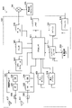
図19Aおよび図19Bは、本実施形態に係る基地局装置1および端末装置2の動作例を示す流れ図である。図19Aおよび図19Bに示したのは、NOMA通信かOMA通信かに応じた送信または受信のための設定等の切り替えを行う、基地局装置1および端末装置2の動作例である。
19A and 19B are flow charts showing operation examples of the
端末装置2は、基地局装置1にNOMA送信または受信をサポートしているかを通知する(ステップS301)。基地局装置1は、端末装置2にNOMA送信またはNOMA受信をする可能性があるか、またはNOMA送信またはNOMA受信を必ずするか、を設定する(ステップS302)。ここで、NOMA送信またはNOMA受信をする可能性がある、と設定した場合、端末装置2は、所定の判断基準に基づいて、NOMA送信またはNOMA受信をするか、またはしないかを決定する。所定の判断基準の例として、例えば基地局装置1から端末装置2に送信されるDCIの情報に基づくものであってもよく、予め決められたルールに従って決定するものであってもよい。
The
その後、例えば、端末装置2にアップリンク送信データが発生したとする(ステップS303)。端末装置2は、必要であればアップリンク用リソースの割り当てを基地局装置1に要求する(ステップS304)。基地局装置1は、必要であれば端末装置2にアップリンク用リソースを割り当てる(ステップS305)。この時、基地局装置1は、必要であれば、NOMA送信をするかどうかも端末装置2へ通知する。端末装置2は、もし判定が必要であれば、NOMA送信をするかどうかを判定する(ステップS306)。ここで、もしNOMA送信をする場合は、端末装置2は、信号の送信に必要な設定等をNOMA送信用に切り替え(ステップS307)、アップリンク送信を実施する(ステップS308)。
After that, for example, uplink transmission data is generated in the terminal device 2 (step S303). The
アップリンク送信信号を受信した基地局装置1は、もし判定が必要であれば、NOMA受信をするかどうかを判定する(ステップS309)。その後、基地局装置1は、NOMA受信かどうかに応じて、信号の受信に必要な設定等を切り替え(ステップS310)、受信処理を実施する(ステップS311)。
The
また、基地局装置1にダウンリンク送信データが発生したとする(ステップS312)もし判定が必要であれば、基地局装置1は、NOMA送信をするかどうかを判定する(ステップS313)。ここで、もしNOMA送信をする場合は、基地局装置1は、信号の送信に必要な設定等をNOMA送信用に切り替え(ステップS314)、端末装置2に信号を送信する(ステップS315)。ダウンリンク送信信号を受信した端末装置2は、もし判定が必要であれば、NOMA受信をするかどうかを判定する(ステップS316)。その後、端末装置2は、NOMA受信かどうかに応じて、信号の受信に必要な設定等を切り替え(ステップS317)、受信処理を実施する(ステップS318)。
Also, if downlink transmission data occurs in the base station apparatus 1 (step S312), if determination is necessary, the
以上、本実施形態に係る基地局装置1または端末装置2の基本的なシーケンスを説明した。続いて、基地局装置1または端末装置2によって、NOMA通信かOMA通信かに応じた送信または受信のために切り替えられる設定等の具体例を説明する。なお、以下において説明する処理は、基地局装置1では制御部103が、端末装置2では制御部203が、それぞれ実行しうる。
The basic sequence of the
(1.DCI Contents)
(1-1.Resource Allocation)
例えば、SpreadingやRepetitionなどのような機能を使ったNOMAの場合、OMAと比較して多くの送信リソースが必要になることが考えられる。そこで、基地局装置1または端末装置2は、NOMAの場合は割り当てリソースの単位をOMAよりも大きくすることで、効率的にリソースを割り当てることが考えられる。リソースの割り当て単位がOMAと比較して大きくなる場合、Resource Allocationで通知をするビット数を減らすことが可能となると考えられる。(1. DCI Contents)
(1-1. Resource Allocation)
For example, NOMA using functions such as Spreading and Repetition may require more transmission resources than OMA. Therefore, in the case of NOMA, the
例えば、基地局装置1または端末装置2は、OMAでは全てのビットを周波数・時間リソース割り当てに使用し、NOMAでは一部のビットを周波数・時間リソース割り当てに、残りのビットをMA signatureの割り当てなどの他の用途に使用してもよい。NOMAの場合、Resource Allocationを通知するフィールドのビット数を削減できる。例えば、OMAでは8ビットを周波数・時間リソース割り当てに使用する場合、NOMAでは4ビットのみを周波数・時間リソース割り当てに使用し、残りの4ビットをMA signatureの割り当てに用いてもよい。
For example, the
(1-2.Modulation and Coding Scheme(MCS))
NOMAでは、非直交軸で複数の異なる信号が多重されて送信される。受信機は、多重された信号から干渉となる信号をキャンセルするなどして、希望信号を復号しなければならない。そこでNOMAでは、Modulation OrderやCode rateを低い値に限定するなどして、より干渉信号に対する耐性を強くすることが考えられる。さらに、値を限定することで、MCSで通知をするビット数を減らすことが可能となると考えられる。例えば、NOMAではQPSK(Quadrature Phase Shift Keying)や16QAM(Quadrature Amplitude Modulation)といった変調方式を用いることができる。(1-2. Modulation and Coding Scheme (MCS))
In NOMA, multiple different signals are multiplexed and transmitted on non-orthogonal axes. The receiver must decode the desired signal by, for example, canceling the interfering signal from the multiplexed signal. Therefore, in NOMA, it is conceivable to limit the Modulation Order and Code rate to low values to make it more resistant to interference signals. Furthermore, by limiting the value, it is considered possible to reduce the number of bits to be notified by MCS. For example, NOMA can use modulation schemes such as QPSK (Quadrature Phase Shift Keying) and 16QAM (Quadrature Amplitude Modulation).
例えば、基地局装置1または端末装置2は、OMAでは全ビットをMCS割り当てに使用し、NOMAでは一部のビットをMCS割り当てに使用し、残りのビットをMA signatureの割り当てなどの他の用途に使用してもよい。NOMAの場合、MCSを通知するフィールドのビット数を削減できる。
For example, the
(1-3.UplinkまたはDownlinkで送信するCBG情報)
UplinkまたはDownlinkで送信するCBG情報は、例えばCBG Transmission information(CBGTI)と呼ばれてもよい。以降では便宜上、CBGTIと呼ぶこととする。NOMAでは、非直交軸で複数の異なる信号が多重されて送信される。受信機は、多重された信号から干渉となる信号をキャンセルするなどして、希望信号を復号しなければならない。そこでNOMAでは、TBサイズをOMAよりも小さくすることで、Code rateを相対的に下げてもよい。NOMAでは、OMAよりもCode rateを相対的に下げることで、より干渉信号に対する耐性を強くすることができる。さらに、NOMAでは、TBサイズをOMAよりも小さくすることで、CBGの数も減少すると考えられるため、CBGTIのビット数を減らすことが可能となる。(1-3. CBG information transmitted by Uplink or Downlink)
CBG information transmitted in Uplink or Downlink may be called CBG Transmission information (CBGTI), for example. For the sake of convenience, it will be referred to as CBGTI hereafter. In NOMA, multiple different signals are multiplexed and transmitted on non-orthogonal axes. The receiver must decode the desired signal by, for example, canceling the interfering signal from the multiplexed signal. Therefore, in NOMA, the code rate may be lowered relatively by making the TB size smaller than that in OMA. In NOMA, resistance to interference signals can be strengthened by lowering the code rate relatively than in OMA. Furthermore, in NOMA, by making the TB size smaller than in OMA, it is thought that the number of CBGs is also reduced, so it is possible to reduce the number of bits of CBGTI.
例えば、基地局装置1または端末装置2は、OMAではCBGTIの通知に使用されているフィールドを、NOMAではMA signatureの割り当てなど他の用途を通知するためのフィールドとして使用してもよい。また基地局装置1または端末装置2は、OMAでは全ビットをCBGTIに使用し、NOMAでは一部ビットをCBGTIに、残りのビットをMA signatureの割り当てなど他の用途に使用してもよい。また基地局装置1または端末装置2は、OMAではCBGTIのフィールドが存在し、NOMAではCBGTIのフィールドが存在しないようにしてもよい。
For example, the
(1-4.送信されたCBGをHARQ合成するかどうかに関する情報)
送信されたCBGをHARQ合成するかどうかは、受信バッファをクリアするかどうか、などと言い換えられる。また、送信されたCBGをHARQ合成するかどうかに関する情報は、CBG flushing out information(CBGFI)と呼ばれてもよい。以降では便宜上、CBGFIと呼ぶこととする。(1-4. Information on whether to HARQ combine the transmitted CBG)
Whether or not to HARQ-synthesize the transmitted CBG can be rephrased as whether or not to clear the reception buffer. Information on whether to HARQ combine the transmitted CBG may also be referred to as CBG flushing out information (CBGFI). For the sake of convenience, it will be called CBGFI hereafter.
NOMAでは、非直交軸で複数の異なる信号を多重して送信をする。NOMAでは、非直交軸で複数の異なる信号が多重されて送信される。受信機は、多重された信号から干渉となる信号をキャンセルするなどして、希望信号を復号しなければならない。そこでNOMAでは、TBサイズをOMAよりも小さくすることで、Code rateを相対的に下げてもよい。NOMAでは、OMAよりもCode rateを相対的に下げることで、より干渉信号に対する耐性を強くすることができる。さらに、TBサイズが小さくなることで、CBG数も減少すると考えられる。これにより、CBGFIビット数を減らす、もしくは常にNOMA送信をするときはTB-basedの送信としてしまうことで、CBGFIのビットを無くすことが可能となると考えられる。 NOMA multiplexes and transmits multiple different signals on non-orthogonal axes. In NOMA, multiple different signals are multiplexed and transmitted on non-orthogonal axes. The receiver must decode the desired signal by, for example, canceling the interfering signal from the multiplexed signal. Therefore, in NOMA, the code rate may be lowered relatively by making the TB size smaller than that in OMA. In NOMA, resistance to interference signals can be strengthened by lowering the code rate relatively than in OMA. Furthermore, it is believed that the number of CBGs will decrease as the TB size decreases. As a result, it is considered possible to eliminate CBGFI bits by reducing the number of CBGFI bits, or by switching to TB-based transmission when NOMA transmission is always used.
例えば、基地局装置1または端末装置2は、OMAではCBGFIの通知に使用されているフィールドを、NOMAではMA signatureの割り当てなど他の用途を通知するためのフィールドとして使用してもよい。また例えば、基地局装置1または端末装置2は、OMAではCBGFIのフィールドが存在し、NOMAではCBGFIのフィールドは存在しないようにしてもよい。
For example, the
(1-5.OMA/NOMA判別用フラグ)
OMAとNOMAを動的に切り替える場合、それぞれの送信で異なるDCIコンテンツとなる可能性がある。その場合、DCIコンテンツの情報サイズを同一になるようにすることで、同一のDCIフォーマットとすることができるため、DCIのブラインドデコーディング数を削減することが可能となる。(1-5. Flag for OMA/NOMA discrimination)
When dynamically switching between OMA and NOMA, each transmission may result in different DCI content. In that case, by making the information size of the DCI content the same, the DCI format can be the same, so it is possible to reduce the number of DCI blind decodings.
DCIコンテンツは異なるが、同一のDCIフォーマットとした場合は、OMAとNOMAのどちらのコンテンツであるかを判別する必要がある。そこで、基地局装置1または端末装置2は、OMAとNOMAを判別するためのフラグをDCIに用意してもよい。図20は、OMAとNOMAを判別するためのフラグの領域の例を示す説明図である。基地局装置1または端末装置2は、NOMAが設定された場合は、OMAとNOMAを判別するためのフラグの領域を設定し、NOMAが設定されなかった場合は、OMAとNOMAを判別するためのフラグの領域を設定しないようにしてもよい。また基地局装置1または端末装置2は、NOMAが設定された場合、新たに判別用のビット(例えば1ビット)の領域を設けても良い。
Although the DCI contents are different, if the DCI format is the same, it is necessary to determine whether the content is OMA or NOMA. Therefore, the
(2.NOMA用TBS Tableまたは数式)
基地局装置1または端末装置2は、TBS IndexとNumber of allocated resource blocksで決定されるTBサイズ(TBS)が、NOMAの場合、OMAと比較して値が小さく(または大きくなる)なるような、異なるTBS Tableまたは数式を設定しても良い。なお、LTEでは、TBS Tableは、TS36.213のTable 7.1.7.2.1-1などに記載されている。表1は、OMA用のTBS Tableの例であり、表2は、NOMA用のTBS Tableの例である。(2. TBS Table or formula for NOMA)
The


また基地局装置1または端末装置2は、OMA用のTableから、NOMA用のTBSを計算する式によってNOMA用のTBSを計算しても良い。例えば基地局装置1または端末装置2は、以下の数式によってNOMA用のTBSを計算しても良い。
(TB size)=(OMA用TBS Tableの値)*(NOMA用変数または定数)Also, the
(TB size) = (value of TBS Table for OMA) * (variable or constant for NOMA)
また基地局装置1または端末装置2は、OMA用のTBSを計算する式に、NOMA用の項やパラメータを追加して、NOMA用のTBSを計算してもよい。NOMA用のパラメータは、例えばSpreading Factorの値などに応じて決まってもよい。例えば基地局装置1または端末装置2は、以下の数式によってNOMA用のTBSを計算しても良い。
(TB size)=(OMA用計算式)*(NOMA用変数または定数)Also, the
(TB size)=(formula for OMA)*(variable or constant for NOMA)
OMA用計算式の例としては、例えばNPRBとITBSで構成される式であってもよい。例えば、Spreading Factor(SF)=2(2倍に拡散するとの意)である場合は、基地局装置1または端末装置2は、TB sizeを、(NOMA用変数)=1/SF=1/2にしてもよい。An example of the OMA calculation formula may be a formula composed of N PRB and ITBS , for example. For example, when Spreading Factor (SF) = 2 (meaning to spread twice), the
(3.NOMA用MCS Tableまたは数式)
基地局装置1または端末装置2は、NOMA通信の際にMCS Indexで決定される変調が、OMAと比較して低次変調もしくは同等になるような、異なるMCS Tableまたは数式を用意しても良い。表3はOMA用のMCS Tableの例である。なおLTEの場合、MCS Tableは、TS36.213のTable 7.1.7.1-1などに記載されている。(3. MCS Table or formula for NOMA)
The

OMA用計算式の例としては、(NOMA用MCS)=(OMA用MCS)*(NOMA用変数または定数)のような数式であっても良い。 An example of the calculation formula for OMA may be a formula such as (MCS for NOMA)=(MCS for OMA)*(variable or constant for NOMA).
(4.NOMA用Codebook Index Tableまたは数式)
基地局装置1または端末装置2は、NOMA通信の際に、Codebook Indexで決定されるPrecoding行列のテーブルを、NOMA用のテーブルに変更してもよい。なおLTEの場合のPrecoding行列は、TS36.211のTable 5.3.3A.2-1などに記載されている。また 基地局装置1または端末装置2は、Codebook Indexで決定されるPrecoding行列を、NOMA用の行列に変更してもよい。また基地局装置1または端末装置2は、NOMA用Precoding行列を数式で求めても良い。数式で求める場合、例えば(NOMA用Precoding行列)=(OMA用Precoding行列)*(NOMA用行列)のような数式であっても良い。(4. Codebook Index Table or formula for NOMA)
During NOMA communication, the
(5.TB-basedまたはCBG-based)
基地局装置1または端末装置2は、準静的にCBG-based送信が設定されない場合は、OMA送信、NOMA送信共に常にTB-based送信をするようにしてもよい。また基地局装置1または端末装置2は、準静的にCBG-based送信が設定された場合、OMA送信ではCBG-based送信、NOMA送信ではTB-based送信をするようにしてもよい。(5. TB-based or CBG-based)
If CBG-based transmission is not set semi-statically, the
(6.Control Resource SetまたはSearch Spaceのリソース)
Control Resource Setは、CORESETやcontrol subband等とも呼ばれうる。以降では便宜上、Control Resource SetをCORESETと呼ぶ。CORESETは、端末装置がブラインドデコードをするSearch Spaceを一つまたは複数含むリソースを表している。図21は、CORESET、Search Space、DCIのリソースの一例を示す説明図である。図21は、一つのCORESET、一つのSearch Space、および一つのDCIを含む例を示す。基地局装置1は端末装置2にCORESETを設定する。端末装置2は、設定されたリソースからSearch Spaceのリソース位置を計算し、Search SpaceをブラインドデコーディングすることでDCIを復号する。(6. Resource of Control Resource Set or Search Space)
Control Resource Set can also be called CORESET, control subband, or the like. For the sake of convenience, the Control Resource Set is hereinafter referred to as CORESET. CORESET represents a resource including one or more Search Spaces for blind decoding by the terminal device. FIG. 21 is an explanatory diagram showing an example of CORESET, Search Space, and DCI resources. FIG. 21 shows an example including one CORESET, one Search Space, and one DCI. The
基地局装置1または端末装置2は、OMA送信用のCORESETとNOMA送信用のCORESETをそれぞれ事前に通知してもよい。図22は、CORESET、Search Space、DCIのリソースの一例を示す説明図である。図22には、OMA送信用のCORESETとNOMA送信用のCORESET、Search Space、DCIのリソースの例が示されている。基地局装置1または端末装置2は、OMA送信なのか、NOMA送信なのかに応じて、CORESETのリソースを切り替えて受信する。また基地局装置1または端末装置2は、受信に成功したCORESETから、OMA送信であるかNOMA送信であるかがわかる。すなわち基地局装置1または端末装置2は、OMA送信用のCORESETの受信に成功すればOMA送信であることがわかり、NOMA送信用のCORESETの受信に成功すればNOMA送信であることがわかる。
The
また基地局装置1または端末装置2は、OMA送信なのか、NOMA送信なのかに応じて、異なるSearch Spaceのリソースをブラインドデコーディングしてもよい。図23は、CORESET、Search Space、DCIのリソースの一例を示す説明図である。図23には、OMA送信用のCORESET、OMA送信用のSearch SpaceとNOMA送信用のSearch Space、DCIのリソースの例が示されている。OMA送信とNOMA送信で同一のCORESETが設定された場合、図23に示したように、CORESETの中でさらにOMA送信用のSearch SpaceとNOMA送信用のSearch Spaceが異なる場合が考えられる。それぞれのSearch Spaceは事前に設定されてもよいし、計算式から認識されてもよい。計算式からNOMA送信用のSearch Spaceを求める場合、例えば、(NOMA用Search Space Resource Index)=(OMA用Search Space Resource Index)*(NOMA用変数または定数)のような数式が用いられても良い。
Also, the
(7.DMRS)
基地局装置1または端末装置2は、OMA送信とNOMA送信とで、DMRSパターンを切り替えてもよい。すなわち、基地局装置1または端末装置2は、OMA送信とNOMA送信とで、直交性を持たせるようにしてもよい。例えば基地局装置1または端末装置2は、OMA送信とNOMA送信とのそれぞれのDMRSに、異なるOrthogonal Cover Code(OCC)を割り当ててもよい。また基地局装置1または端末装置2は、OMA送信とNOMA送信とのそれぞれのDMRSに、異なるCyclic Shiftパターンを割り当ててもよい。(7. DMRS)
The
(8.HARQ Process NumberまたはHARQ Process数)
基地局装置1または端末装置2は、OMA送信とNOMA送信とで、HARQ Process NumberまたはHARQ Process数を切り替えても良い。図24は、OMA送信とNOMA送信とで、HARQ Process Numberを切り替える例を示す説明図である。基地局装置1または端末装置2は、OMA送信とNOMA送信の両方を送信する可能性がある場合、OMA送信のHARQ Process Numberを#0と#1、NOMA送信のHARQ Process Numberを#2、#3に分けても良い。図25は、OMA送信とNOMA送信とで、HARQ Process数を切り替える例を示す説明図である。基地局装置1または端末装置2は、OMA送信とNOMA送信のいずれかを送信する場合、OMA送信のHARQ Process数は4、NOMA送信のHARQ Process数は2などのように分けてもよい。(8. HARQ Process Number or HARQ Process Number)
The
(9.Grant-based送信またはGrant-free送信)
基地局装置1または端末装置2は、OMA送信とNOMA送信とで、Grant-based送信を行うか、またはGrant-free送信を行うかを切り替えても良い。例えば、基地局装置1または端末装置2は、Grant-based送信はOMA送信、Grant-free送信はNOMA送信のように切り替えてもよい。例えば、基地局装置1または端末装置2は、Grant-based送信はOMA送信またはNOMA送信、Grant-free送信は常にNOMA送信のように切り替えてもよい。Grant-based送信をOMA送信またはNOMA送信のどちらで送信するかは、例えばDCIで通知されうる。(9. Grant-based transmission or Grant-free transmission)
The
(10.CSI Feedback)
基地局装置1または端末装置2は、OMA送信とNOMA送信とで、CSI Feedbackを切り替えても良い。CSI Feedbackは、例えば、Channel Quality Indicator(CQI)、Precoding Matrix Indicator(PMI)、Rank Indicator(RI)などが挙げられる。NOMA送信は非直交軸で異なる信号を多重するため、信号間の干渉が発生する。そのため、NOMA送信はOMA送信と比べて、チャネル状態は悪くなることが想定される。そこで基地局装置1または端末装置2は、NOMA送信の場合は、OMA送信と比較して低いCQIをFeedbackしてもよく、低いRankをFeedbackしてもよい。NOMA送信の場合、Precoding MatrixがOMA送信と異なる場合が考えられる。そこで基地局装置1または端末装置2は、NOMA送信の場合は、OMA送信と異なるPMIをFeedbackしてもよい。(10. CSI feedback)
The
(11.Power Control)
基地局装置1または端末装置2は、OMA送信とNOMA送信とで、Power Controlの式を切り替えても良い。また、基地局装置1または端末装置2は、OMA送信とNOMA送信とで、Power Controlの実行の有無を切り替えても良い。NOMA送信の方式によっては、電力差をつけた非直交多重が考えられる。そこで基地局装置1または端末装置2は、NOMA送信の際は、OMA送信とは異なるPower controlの式を用いても良く、OMA送信のPower Controlの式にNOMA送信のパラメータを追加してもよい。また基地局装置1または端末装置2は、Power ControlのON/OFFを切り替えてもよい。これより、端末装置2から基地局装置1に送信をしたときの基地局装置1での受信電力に、端末装置2の間で差をつけることが可能となる。端末装置2は、OMA送信をするかNOMA送信をするかによって、Power controlの方式を切り替えてもよい。(11. Power Control)
The
(12.初送または再送)
基地局装置1または端末装置2は、OMA送信とNOMA送信とで、初送と再送を切り替えても良い。例えば、基地局装置1または端末装置2は、初送をNOMA送信で送信したとする。もし相手が受信に失敗した場合、基地局装置1または端末装置2は、再送はOMA送信に切り替えても良い。再送をOMA送信にして直交リソースを使用することで、再送時の信頼性の向上が期待できる。(12. Initial transmission or retransmission)
The
(13.RNTI)
基地局装置1または端末装置2は、OMA送信とNOMA送信とで、RNTIを切り替えても良い。例えば、OMA送信用のDCIとNOMA送信用のDCIが同じDCI formatであるとする。この場合、OMA送信用のDCIであるか、NOMA送信用のDCIであるかを区別する方法の一つとして、DCIのCRC Scrambleから判定する方法が考えられる。例えば、送信機側では、OMA送信の場合は、DCIのCRCをOMA用のRNTIでスクランブルし、一方でNOMA送信の場合は、DCIのCRCをNOMA用のRNTIでスクランブルする、といったように、RNTIの切り替えを行っても良い。DCIを受信した受信機は、DCIを復号後、CRCをOMA用のRNTIとNOMA用のRNTIの両方でデスクランブルを試みることで、CRCチェックの成否からOMA送信であるかNOMA送信であるかを判定することが可能となる。(13. RNTI)
The
以上の実施例ではOMA送信とNOMA送信の切り替え例を示したが、NOMA送信の種類で切り替えてもよい。例えば、Spreadingの機能を使用するNOMA送信をする場合と、Spreadingの機能を使用しないNOMA送信またはOMA送信をする場合で切り替える、などである。ここで、Spreadingの機能を使用した場合を例に挙げたが、これによらず、InterleaveやRepetitionといった機能でもよい。また、以上ではダウンリンク、アップリンクの場合の実施例を主に示したが、これらに限定されるものではなく、Device to Device(D2D)などのサイドリンク、リレー端末との通信にも適用可能である。また、以上の実施例は、どれか一つのみを適用しても良いし、複数の方法を組み合わせて実施しても良い。また、本技術は上記実施例に限られない。 Although an example of switching between OMA transmission and NOMA transmission has been shown in the above embodiment, switching may be performed depending on the type of NOMA transmission. For example, switching between NOMA transmission that uses the spreading function and NOMA or OMA transmission that does not use the spreading function. Here, the case where the function of Spreading is used is given as an example, but functions such as Interleave and Repetition may be used instead of this. In addition, the above mainly shows examples for downlink and uplink, but it is not limited to these, and can also be applied to sidelinks such as Device to Device (D2D) and communication with relay terminals. is. Moreover, only one of the above embodiments may be applied, or a plurality of methods may be combined and implemented. Moreover, the present technology is not limited to the above embodiments.
<2.応用例>
本開示に係る技術は、様々な製品へ応用可能である。例えば、基地局装置1は、マクロeNB又はスモールeNBなどのいずれかの種類のeNB(evolved Node B)として実現されてもよい。スモールeNBは、ピコeNB、マイクロeNB又はホーム(フェムト)eNBなどの、マクロセルよりも小さいセルをカバーするeNBであってよい。その代わりに、基地局装置1は、NodeB又はBTS(Base Transceiver Station)などの他の種類の基地局として実現されてもよい。基地局装置1は、無線通信を制御する本体(基地局装置ともいう)と、本体とは別の場所に配置される1つ以上のRRH(Remote Radio Head)とを含んでもよい。また、後述する様々な種類の端末が一時的に又は半永続的に基地局機能を実行することにより、基地局装置1として動作してもよい。<2. Application example>
The technology according to the present disclosure can be applied to various products. For example, the
また、例えば、端末装置2は、スマートフォン、タブレットPC(Personal Computer)、ノートPC、携帯型ゲーム端末、携帯型/ドングル型のモバイルルータ若しくはデジタルカメラなどのモバイル端末、又はカーナビゲーション装置などの車載端末として実現されてもよい。また、端末装置2は、M2M(Machine To Machine)通信を行う端末(MTC(Machine Type Communication)端末ともいう)として実現されてもよい。さらに、端末装置2は、これら端末に搭載される無線通信モジュール(例えば、1つのダイで構成される集積回路モジュール)であってもよい。
Further, for example, the
<2.1.基地局装置に関する応用例>
(第1の応用例)
図26は、本開示に係る技術が適用され得るeNBの概略的な構成の第1の例を示すブロック図である。eNB800は、1つ以上のアンテナ810、及び基地局装置820を有する。各アンテナ810及び基地局装置820は、RFケーブルを介して互いに接続され得る。<2.1. Application example related to base station device>
(First application example)
FIG. 26 is a block diagram showing a first example of a schematic configuration of an eNB to which technology according to the present disclosure may be applied. The
アンテナ810の各々は、単一の又は複数のアンテナ素子(例えば、MIMOアンテナを構成する複数のアンテナ素子)を有し、基地局装置820による無線信号の送受信のために使用される。eNB800は、図26に示したように複数のアンテナ810を有し、複数のアンテナ810は、例えばeNB800が使用する複数の周波数帯域にそれぞれ対応してもよい。なお、図26にはeNB800が複数のアンテナ810を有する例を示したが、eNB800は単一のアンテナ810を有してもよい。
Each of
基地局装置820は、コントローラ821、メモリ822、ネットワークインタフェース823及び無線通信インタフェース825を備える。
コントローラ821は、例えばCPU又はDSPであってよく、基地局装置820の上位レイヤの様々な機能を動作させる。例えば、コントローラ821は、無線通信インタフェース825により処理された信号内のデータからデータパケットを生成し、生成したパケットをネットワークインタフェース823を介して転送する。コントローラ821は、複数のベースバンドプロセッサからのデータをバンドリングすることによりバンドルドパケットを生成し、生成したバンドルドパケットを転送してもよい。また、コントローラ821は、無線リソース管理(Radio Resource Control)、無線ベアラ制御(Radio Bearer Control)、移動性管理(Mobility Management)、流入制御(Admission Control)又はスケジューリング(Scheduling)などの制御を実行する論理的な機能を有してもよい。また、当該制御は、周辺のeNB又はコアネットワークノードと連携して実行されてもよい。メモリ822は、RAM及びROMを含み、コントローラ821により実行されるプログラム、及び様々な制御データ(例えば、端末リスト、送信電力データ及びスケジューリングデータなど)を記憶する。
ネットワークインタフェース823は、基地局装置820をコアネットワーク824に接続するための通信インタフェースである。コントローラ821は、ネットワークインタフェース823を介して、コアネットワークノード又は他のeNBと通信してもよい。その場合に、eNB800と、コアネットワークノード又は他のeNBとは、論理的なインタフェース(例えば、S1インタフェース又はX2インタフェース)により互いに接続されてもよい。ネットワークインタフェース823は、有線通信インタフェースであってもよく、又は無線バックホールのための無線通信インタフェースであってもよい。ネットワークインタフェース823が無線通信インタフェースである場合、ネットワークインタフェース823は、無線通信インタフェース825により使用される周波数帯域よりもより高い周波数帯域を無線通信に使用してもよい。
A
無線通信インタフェース825は、LTE(Long Term Evolution)又はLTE-Advancedなどのいずれかのセルラー通信方式をサポートし、アンテナ810を介して、eNB800のセル内に位置する端末に無線接続を提供する。無線通信インタフェース825は、典型的には、ベースバンド(BB)プロセッサ826及びRF回路827などを含み得る。BBプロセッサ826は、例えば、符号化/復号、変調/復調及び多重化/逆多重化などを行なってよく、各レイヤ(例えば、L1、MAC(Medium Access Control)、RLC(Radio Link Control)及びPDCP(Packet Data Convergence Protocol))の様々な信号処理を実行する。BBプロセッサ826は、コントローラ821の代わりに、上述した論理的な機能の一部又は全部を有してもよい。BBプロセッサ826は、通信制御プログラムを記憶するメモリ、当該プログラムを実行するプロセッサ及び関連する回路を含むモジュールであってもよく、BBプロセッサ826の機能は、上記プログラムのアップデートにより変更可能であってもよい。また、上記モジュールは、基地局装置820のスロットに挿入されるカード若しくはブレードであってもよく、又は上記カード若しくは上記ブレードに搭載されるチップであってもよい。一方、RF回路827は、ミキサ、フィルタ及びアンプなどを含んでもよく、アンテナ810を介して無線信号を送受信する。
無線通信インタフェース825は、図26に示したように複数のBBプロセッサ826を含み、複数のBBプロセッサ826は、例えばeNB800が使用する複数の周波数帯域にそれぞれ対応してもよい。また、無線通信インタフェース825は、図26に示したように複数のRF回路827を含み、複数のRF回路827は、例えば複数のアンテナ素子にそれぞれ対応してもよい。なお、図26には無線通信インタフェース825が複数のBBプロセッサ826及び複数のRF回路827を含む例を示したが、無線通信インタフェース825は単一のBBプロセッサ826又は単一のRF回路827を含んでもよい。
The
図26に示したeNB800において、図6を参照して説明した上位層処理部101、制御部103、受信部105及び/又は送信部107は、無線通信インタフェース825(例えば、BBプロセッサ826及び/又はRF回路827)、コントローラ821及び/又はネットワークインタフェース823において実装されてもよい。例えば、無線通信インタフェース825、コントローラ821及び/又はネットワークインタフェース823は、第一の制御情報及び第二の制御情報を送信したり、制御情報要求を受信して対応する第三の制御情報を送信したりする。例えば、無線通信インタフェース825に含まれるプロセッサにおいて、これらの動作を行うための機能が実装されてもよい。このような動作を行う装置として、eNB800、基地局装置820又は上記モジュールが提供されてもよく、プロセッサに上記動作を行わせるためのプログラムが提供されてもよい。また、上記プログラムを記録した読み取り可能な記録媒体が提供されてもよい。また、送受信アンテナ109は、アンテナ810において実装されてもよい。
In the
(第2の応用例)
図27は、本開示に係る技術が適用され得るeNBの概略的な構成の第2の例を示すブロック図である。eNB830は、1つ以上のアンテナ840、基地局装置850、及びRRH860を有する。各アンテナ840及びRRH860は、RFケーブルを介して互いに接続され得る。また、基地局装置850及びRRH860は、光ファイバケーブルなどの高速回線で互いに接続され得る。(Second application example)
FIG. 27 is a block diagram showing a second example of a schematic configuration of an eNB to which technology according to the present disclosure may be applied.
アンテナ840の各々は、単一の又は複数のアンテナ素子(例えば、MIMOアンテナを構成する複数のアンテナ素子)を有し、RRH860による無線信号の送受信のために使用される。eNB830は、図27に示したように複数のアンテナ840を有し、複数のアンテナ840は、例えばeNB830が使用する複数の周波数帯域にそれぞれ対応してもよい。なお、図27はeNB830が複数のアンテナ840を有する例を示したが、eNB830は単一のアンテナ840を有してもよい。
Each of
基地局装置850は、コントローラ851、メモリ852、ネットワークインタフェース853、無線通信インタフェース855及び接続インタフェース857を備える。コントローラ851、メモリ852及びネットワークインタフェース853は、図26を参照して説明したコントローラ821、メモリ822及びネットワークインタフェース823と同様のものである。
The
無線通信インタフェース855は、LTE又はLTE-Advancedなどのいずれかのセルラー通信方式をサポートし、RRH860及びアンテナ840を介して、RRH860に対応するセクタ内に位置する端末に無線接続を提供する。無線通信インタフェース855は、典型的には、BBプロセッサ856などを含み得る。BBプロセッサ856は、接続インタフェース857を介してRRH860のRF回路864と接続されることを除き、図26を参照して説明したBBプロセッサ826と同様のものである。無線通信インタフェース855は、図27に示したように複数のBBプロセッサ856を含み、複数のBBプロセッサ856は、例えばeNB830が使用する複数の周波数帯域にそれぞれ対応してもよい。なお、図27には無線通信インタフェース855が複数のBBプロセッサ856を含む例を示したが、無線通信インタフェース855は単一のBBプロセッサ856を含んでもよい。
接続インタフェース857は、基地局装置850(無線通信インタフェース855)をRRH860と接続するためのインタフェースである。接続インタフェース857は、基地局装置850(無線通信インタフェース855)とRRH860とを接続する上記高速回線での通信のための通信モジュールであってもよい。
A
また、RRH860は、接続インタフェース861及び無線通信インタフェース863を備える。
The
接続インタフェース861は、RRH860(無線通信インタフェース863)を基地局装置850と接続するためのインタフェースである。接続インタフェース861は、上記高速回線での通信のための通信モジュールであってもよい。
The
無線通信インタフェース863は、アンテナ840を介して無線信号を送受信する。無線通信インタフェース863は、典型的には、RF回路864などを含み得る。RF回路864は、ミキサ、フィルタ及びアンプなどを含んでもよく、アンテナ840を介して無線信号を送受信する。無線通信インタフェース863は、図27に示したように複数のRF回路864を含み、複数のRF回路864は、例えば複数のアンテナ素子にそれぞれ対応してもよい。なお、図27には無線通信インタフェース863が複数のRF回路864を含む例を示したが、無線通信インタフェース863は単一のRF回路864を含んでもよい。
図27に示したeNB830において、図6を参照して説明した上位層処理部101、制御部103、受信部105及び/又は送信部107は、無線通信インタフェース855、無線通信インタフェース863(例えば、BBプロセッサ856及び/又はRF回路864)、コントローラ851及び/又はネットワークインタフェース853において実装されてもよい。例えば、無線通信インタフェース855、無線通信インタフェース863、コントローラ851及び/又はネットワークインタフェース853は、第一の制御情報及び第二の制御情報を送信したり、制御情報要求を受信して対応する第三の制御情報を送信したりする。例えば、無線通信インタフェース855及び/又は無線通信インタフェース863に含まれるプロセッサにおいて、これらの動作を行うための機能が実装されてもよい。このような動作を行う装置として、eNB830、基地局装置850又は上記モジュールが提供されてもよく、プロセッサに上記動作を行わせるためのプログラムが提供されてもよい。また、上記プログラムを記録した読み取り可能な記録媒体が提供されてもよい。また、送受信アンテナ109は、アンテナ840において実装されてもよい。
In the
<2.2.端末装置に関する応用例>
(第1の応用例)
図28は、本開示に係る技術が適用され得るスマートフォン900の概略的な構成の一例を示すブロック図である。スマートフォン900は、プロセッサ901、メモリ902、ストレージ903、外部接続インタフェース904、カメラ906、センサ907、マイクロフォン908、入力デバイス909、表示デバイス910、スピーカ911、無線通信インタフェース912、1つ以上のアンテナスイッチ915、1つ以上のアンテナ916、バス917、バッテリー918及び補助コントローラ919を備える。<2.2. Application example related to terminal device>
(First application example)
FIG. 28 is a block diagram showing an example of a schematic configuration of a
プロセッサ901は、例えばCPU又はSoC(System on Chip)であってよく、スマートフォン900のアプリケーションレイヤ及びその他のレイヤの機能を制御する。メモリ902は、RAM及びROMを含み、プロセッサ901により実行されるプログラム及びデータを記憶する。ストレージ903は、半導体メモリ又はハードディスクなどの記憶媒体を含み得る。外部接続インタフェース904は、メモリーカード又はUSB(Universal Serial Bus)デバイスなどの外付けデバイスをスマートフォン900へ接続するためのインタフェースである。
The
カメラ906は、例えば、CCD(Charge Coupled Device)又はCMOS(Complementary Metal Oxide Semiconductor)などの撮像素子を有し、撮像画像を生成する。センサ907は、例えば、測位センサ、ジャイロセンサ、地磁気センサ及び加速度センサなどのセンサ群を含み得る。マイクロフォン908は、スマートフォン900へ入力される音声を音声信号へ変換する。入力デバイス909は、例えば、表示デバイス910の画面上へのタッチを検出するタッチセンサ、キーパッド、キーボード、ボタン又はスイッチなどを含み、ユーザからの操作又は情報入力を受け付ける。表示デバイス910は、液晶ディスプレイ(LCD)又は有機発光ダイオード(OLED)ディスプレイなどの画面を有し、スマートフォン900の出力画像を表示する。スピーカ911は、スマートフォン900から出力される音声信号を音声に変換する。
The
無線通信インタフェース912は、LTE又はLTE-Advancedなどのいずれかのセルラー通信方式をサポートし、無線通信を実行する。無線通信インタフェース912は、典型的には、BBプロセッサ913及びRF回路914などを含み得る。BBプロセッサ913は、例えば、符号化/復号、変調/復調及び多重化/逆多重化などを行なってよく、無線通信のための様々な信号処理を実行する。一方、RF回路914は、ミキサ、フィルタ及びアンプなどを含んでもよく、アンテナ916を介して無線信号を送受信する。無線通信インタフェース912は、BBプロセッサ913及びRF回路914を集積したワンチップのモジュールであってもよい。無線通信インタフェース912は、図28に示したように複数のBBプロセッサ913及び複数のRF回路914を含んでもよい。なお、図28には無線通信インタフェース912が複数のBBプロセッサ913及び複数のRF回路914を含む例を示したが、無線通信インタフェース912は単一のBBプロセッサ913又は単一のRF回路914を含んでもよい。
A
さらに、無線通信インタフェース912は、セルラー通信方式に加えて、近距離無線通信方式、近接無線通信方式又は無線LAN(Local Area Network)方式などの他の種類の無線通信方式をサポートしてもよく、その場合に、無線通信方式ごとのBBプロセッサ913及びRF回路914を含んでもよい。
In addition, the
アンテナスイッチ915の各々は、無線通信インタフェース912に含まれる複数の回路(例えば、異なる無線通信方式のための回路)の間でアンテナ916の接続先を切り替える。
Each of the
アンテナ916の各々は、単一の又は複数のアンテナ素子(例えば、MIMOアンテナを構成する複数のアンテナ素子)を有し、無線通信インタフェース912による無線信号の送受信のために使用される。スマートフォン900は、図28に示したように複数のアンテナ916を有してもよい。なお、図28にはスマートフォン900が複数のアンテナ916を有する例を示したが、スマートフォン900は単一のアンテナ916を有してもよい。
Each of
さらに、スマートフォン900は、無線通信方式ごとにアンテナ916を備えてもよい。その場合に、アンテナスイッチ915は、スマートフォン900の構成から省略されてもよい。
Further,
バス917は、プロセッサ901、メモリ902、ストレージ903、外部接続インタフェース904、カメラ906、センサ907、マイクロフォン908、入力デバイス909、表示デバイス910、スピーカ911、無線通信インタフェース912及び補助コントローラ919を互いに接続する。バッテリー918は、図中に破線で部分的に示した給電ラインを介して、図28に示したスマートフォン900の各ブロックへ電力を供給する。補助コントローラ919は、例えば、スリープモードにおいて、スマートフォン900の必要最低限の機能を動作させる。
A
図28に示したスマートフォン900において、図7を参照して説明した上位層処理部201、制御部203、受信部205及び/又は送信部207は、無線通信インタフェース912(例えば、RF回路914及び/又はBBプロセッサ913)、プロセッサ901、及び/又は補助コントローラ919において実装されてもよい。例えば、無線通信インタフェース912、プロセッサ901、及び/又は補助コントローラ919は、第一の制御情報及び第二の制御情報を受信したり、制御情報要求を送信して対応する第三の制御情報を受信したりする。例えば、無線通信インタフェース912に含まれるプロセッサにおいて、これらの動作を行うための機能が実装されてもよい。このような動作を行う装置として、スマートフォン900又は上記モジュールが提供されてもよく、プロセッサに上記動作を行わせるためのプログラムが提供されてもよい。また、上記プログラムを記録した読み取り可能な記録媒体が提供されてもよい。また、送受信アンテナ209は、アンテナ916において実装されてもよい。
In the
(第2の応用例)
図29は、本開示に係る技術が適用され得るカーナビゲーション装置920の概略的な構成の一例を示すブロック図である。カーナビゲーション装置920は、プロセッサ921、メモリ922、GPS(Global Positioning System)モジュール924、センサ925、データインタフェース926、コンテンツプレーヤ927、記憶媒体インタフェース928、入力デバイス929、表示デバイス930、スピーカ931、無線通信インタフェース933、1つ以上のアンテナスイッチ936、1つ以上のアンテナ937及びバッテリー938を備える。(Second application example)
FIG. 29 is a block diagram showing an example of a schematic configuration of a
プロセッサ921は、例えばCPU又はSoCであってよく、カーナビゲーション装置920のナビゲーション機能及びその他の機能を制御する。メモリ922は、RAM及びROMを含み、プロセッサ921により実行されるプログラム及びデータを記憶する。
The
GPSモジュール924は、GPS衛星から受信されるGPS信号を用いて、カーナビゲーション装置920の位置(例えば、緯度、経度及び高度)を測定する。センサ925は、例えば、ジャイロセンサ、地磁気センサ及び気圧センサなどのセンサ群を含み得る。データインタフェース926は、例えば、図示しない端子を介して車載ネットワーク941に接続され、車速データなどの車両側で生成されるデータを取得する。
コンテンツプレーヤ927は、記憶媒体インタフェース928に挿入される記憶媒体(例えば、CD又はDVD)に記憶されているコンテンツを再生する。入力デバイス929は、例えば、表示デバイス930の画面上へのタッチを検出するタッチセンサ、ボタン又はスイッチなどを含み、ユーザからの操作又は情報入力を受け付ける。表示デバイス930は、LCD又はOLEDディスプレイなどの画面を有し、ナビゲーション機能又は再生されるコンテンツの画像を表示する。スピーカ931は、ナビゲーション機能又は再生されるコンテンツの音声を出力する。
無線通信インタフェース933は、LTE又はLTE-Advancedなどのいずれかのセルラー通信方式をサポートし、無線通信を実行する。無線通信インタフェース933は、典型的には、BBプロセッサ934及びRF回路935などを含み得る。BBプロセッサ934は、例えば、符号化/復号、変調/復調及び多重化/逆多重化などを行なってよく、無線通信のための様々な信号処理を実行する。一方、RF回路935は、ミキサ、フィルタ及びアンプなどを含んでもよく、アンテナ937を介して無線信号を送受信する。無線通信インタフェース933は、BBプロセッサ934及びRF回路935を集積したワンチップのモジュールであってもよい。無線通信インタフェース933は、図29に示したように複数のBBプロセッサ934及び複数のRF回路935を含んでもよい。なお、図29には無線通信インタフェース933が複数のBBプロセッサ934及び複数のRF回路935を含む例を示したが、無線通信インタフェース933は単一のBBプロセッサ934又は単一のRF回路935を含んでもよい。
A
さらに、無線通信インタフェース933は、セルラー通信方式に加えて、近距離無線通信方式、近接無線通信方式又は無線LAN方式などの他の種類の無線通信方式をサポートしてもよく、その場合に、無線通信方式ごとのBBプロセッサ934及びRF回路935を含んでもよい。
Furthermore, the
アンテナスイッチ936の各々は、無線通信インタフェース933に含まれる複数の回路(例えば、異なる無線通信方式のための回路)の間でアンテナ937の接続先を切り替える。
Each
アンテナ937の各々は、単一の又は複数のアンテナ素子(例えば、MIMOアンテナを構成する複数のアンテナ素子)を有し、無線通信インタフェース933による無線信号の送受信のために使用される。カーナビゲーション装置920は、図29に示したように複数のアンテナ937を有してもよい。なお、図29にはカーナビゲーション装置920が複数のアンテナ937を有する例を示したが、カーナビゲーション装置920は単一のアンテナ937を有してもよい。
Each of the
さらに、カーナビゲーション装置920は、無線通信方式ごとにアンテナ937を備えてもよい。その場合に、アンテナスイッチ936は、カーナビゲーション装置920の構成から省略されてもよい。
Furthermore, the
バッテリー938は、図中に破線で部分的に示した給電ラインを介して、図29に示したカーナビゲーション装置920の各ブロックへ電力を供給する。また、バッテリー938は、車両側から給電される電力を蓄積する。
A
図29に示したカーナビゲーション装置920において、図7を参照して説明した上位層処理部201、制御部203、受信部205及び/又は送信部207は、無線通信インタフェース933(例えば、RF回路935及び/又はBBプロセッサ934)及び/又はプロセッサ921において実装されてもよい。例えば、無線通信インタフェース933及び/又はプロセッサ921は、第一の制御情報及び第二の制御情報を受信したり、制御情報要求を送信して対応する第三の制御情報を受信したりする。例えば、無線通信インタフェース933に含まれるプロセッサにおいて、これらの動作を行うための機能が実装されてもよい。このような動作を行う装置として、カーナビゲーション装置920又は上記モジュールが提供されてもよく、プロセッサに上記動作を行わせるためのプログラムが提供されてもよい。また、上記プログラムを記録した読み取り可能な記録媒体が提供されてもよい。また、送受信アンテナ209は、アンテナ937において実装されてもよい。
In the
また、本開示に係る技術は、上述したカーナビゲーション装置920の1つ以上のブロックと、車載ネットワーク941と、車両側モジュール942とを含む車載システム(又は車両)940として実現されてもよい。車両側モジュール942は、車速、エンジン回転数又は故障情報などの車両側データを生成し、生成したデータを車載ネットワーク941へ出力する。
Also, the technology according to the present disclosure may be implemented as an in-vehicle system (or vehicle) 940 including one or more blocks of the
なお、上述の説明でeNBとして示したものは、gNB(gNodeB、next Generation NodeB)であってもよい。 Note that what is indicated as eNB in the above description may be gNB (gNodeB, next Generation NodeB).
<3.まとめ>
以上説明したように本開示の実施の形態によれば、実行するのがNOMA送信かOMA送信かに応じた送信または受信のための設定等の切り替えを行うことで、無線通信をより効率的に実施することが可能基地局装置1及び端末装置2を提供することができる。<3. Summary>
As described above, according to the embodiments of the present disclosure, wireless communication can be performed more efficiently by switching settings for transmission or reception depending on whether NOMA transmission or OMA transmission is to be executed. It is possible to provide the
本明細書の各装置が実行する処理における各ステップは、必ずしもシーケンス図またはフローチャートとして記載された順序に沿って時系列に処理する必要はない。例えば、各装置が実行する処理における各ステップは、フローチャートとして記載した順序と異なる順序で処理されても、並列的に処理されてもよい。 Each step in the processing executed by each device in this specification does not necessarily have to be processed in chronological order according to the order described as a sequence diagram or flowchart. For example, each step in the process executed by each device may be processed in an order different from the order described as the flowchart, or may be processed in parallel.
また、各装置に内蔵されるCPU、ROMおよびRAMなどのハードウェアを、上述した各装置の構成と同等の機能を発揮させるためのコンピュータプログラムも作成可能である。また、該コンピュータプログラムを記憶させた記憶媒体も提供されることが可能である。また、機能ブロック図で示したそれぞれの機能ブロックをハードウェアで構成することで、一連の処理をハードウェアで実現することもできる。 It is also possible to create a computer program for making hardware such as a CPU, ROM, and RAM built into each device exhibit functions equivalent to those of the configuration of each device described above. A storage medium storing the computer program can also be provided. A series of processing can also be realized by hardware by configuring each functional block shown in the functional block diagram by hardware.
以上、添付図面を参照しながら本開示の好適な実施形態について詳細に説明したが、本開示の技術的範囲はかかる例に限定されない。本開示の技術分野における通常の知識を有する者であれば、特許請求の範囲に記載された技術的思想の範疇内において、各種の変更例または修正例に想到し得ることは明らかであり、これらについても、当然に本開示の技術的範囲に属するものと了解される。 Although the preferred embodiments of the present disclosure have been described in detail above with reference to the accompanying drawings, the technical scope of the present disclosure is not limited to such examples. It is obvious that those who have ordinary knowledge in the technical field of the present disclosure can conceive of various modifications or modifications within the scope of the technical idea described in the claims. is naturally within the technical scope of the present disclosure.
また、本明細書に記載された効果は、あくまで説明的または例示的なものであって限定的ではない。つまり、本開示に係る技術は、上記の効果とともに、または上記の効果に代えて、本明細書の記載から当業者には明らかな他の効果を奏しうる。 Also, the effects described herein are merely illustrative or exemplary, and are not limiting. In other words, the technology according to the present disclosure can produce other effects that are obvious to those skilled in the art from the description of this specification, in addition to or instead of the above effects.
なお、以下のような構成も本開示の技術的範囲に属する。
(1)
無線通信を行う通信部と、
前記無線通信が非直交多元接続であるか直交多元接続であるかに応じて前記通信部による送信制御または受信制御に用いられる設定を選択する制御部と、
を備える、無線通信装置。
(2)
前記制御部は、前記設定として前記送信制御または前記受信制御に用いられるパラメータに関する設定を選択する、前記(1)に記載の無線通信装置。
(3)
前記制御部は、前記設定として下りリンク制御情報におけるパラメータに関する設定を選択する、前記(2)に記載の無線通信装置。
(4)
前記制御部は、前記設定として下りリンク制御情報におけるリソースの割り当てに関する設定を選択する、前記(3)に記載の無線通信装置。
(5)
前記制御部は、前記設定として下りリンク制御情報における、前記無線通信が非直交多元接続であるか直交多元接続であるかを判別するフラグに関する設定を選択する、前記(3)に記載の無線通信装置。
(6)
前記制御部は、前記設定としてトランスポートブロックサイズに関する設定を選択する、前記(3)に記載の無線通信装置。
(7)
前記制御部は、前記無線通信が非直交多元接続である場合、直交多元接続の場合の前記トランスポートブロックサイズに関する設定に、非直交多元接続用の設定を追加する、前記(6)に記載の無線通信装置。
(8)
前記制御部は、前記設定として前記無線通信における送信方式に関する設定を選択する、前記(1)に記載の無線通信装置。
(9)
前記制御部は、前記無線通信が非直交多元接続である場合、前記設定として前記無線通信の相手の装置からの事前許可を不要とする送信方式を選択する、前記(8)に記載の無線通信装置。
(10)
前記制御部は、前記設定として前記無線通信における送信単位に関する設定を選択する、前記(8)に記載の無線通信装置。
(11)
前記制御部は、前記無線通信が非直交多元接続である場合、前記無線通信における送信単位がトランスポートブロック単位となる送信方式を選択する、前記(10)に記載の無線通信装置。
(12)
前記制御部は、前記設定として前記送信制御または前記受信制御に用いられるリソースに関する設定を選択する、前記(1)に記載の無線通信装置。
(13)
前記制御部は、前記無線通信が非直交多元接続または直交多元接続で用いられるリソースセットを前記無線通信の相手の装置へ予め通知する、前記(12)に記載の無線通信装置。
(14)
前記制御部は、前記非直交多元接続の実施の有無を判定する、前記(1)~(13)のいずれかに記載の無線通信装置。
(15)
前記制御部は、受信に成功したリソースセットからに前記非直交多元接続の実施の有無を判定する、前記(14)に記載の無線通信装置。
(16)
前記制御部は、サーチスペースに対するブラインドデコーディングの結果に基づいて前記非直交多元接続の実施の有無を判定する、前記(14)に記載の無線通信装置。
(17)
プロセッサが、
無線通信を行うことと、
前記無線通信が非直交多元接続であるか直交多元接続であるかに応じて前記無線通信における送信制御または受信制御に用いられる設定を切り替えることと、
を実行することを含む、無線通信方法。
(18)
コンピュータに、
無線通信を行うことと、
前記無線通信が非直交多元接続であるか直交多元接続であるかに応じて前記無線通信における送信制御または受信制御に用いられる設定を切り替えることと、
を実行させる、コンピュータプログラム。Note that the following configuration also belongs to the technical scope of the present disclosure.
(1)
a communication unit that performs wireless communication;
a control unit that selects settings to be used for transmission control or reception control by the communication unit according to whether the wireless communication is non-orthogonal multiple access or orthogonal multiple access;
A wireless communication device comprising:
(2)
The wireless communication device according to (1), wherein the control unit selects a setting related to a parameter used for the transmission control or the reception control as the setting.
(3)
The wireless communication device according to (2), wherein the control unit selects settings related to parameters in downlink control information as the settings.
(4)
The radio communication apparatus according to (3), wherein the control unit selects a setting related to resource allocation in downlink control information as the setting.
(5)
The wireless communication according to (3), wherein the control unit selects, as the setting, a setting regarding a flag for determining whether the wireless communication is non-orthogonal multiple access or orthogonal multiple access in downlink control information. Device.
(6)
The wireless communication device according to (3), wherein the control unit selects a setting related to a transport block size as the setting.
(7)
The above (6), wherein, when the wireless communication is non-orthogonal multiple access, the control unit adds settings for non-orthogonal multiple access to settings related to the transport block size for orthogonal multiple access. wireless communication device.
(8)
The wireless communication device according to (1), wherein the control unit selects a setting related to a transmission method in the wireless communication as the setting.
(9)
The wireless communication according to (8), wherein, when the wireless communication is non-orthogonal multiple access, the control unit selects, as the setting, a transmission method that does not require prior permission from a device of the wireless communication partner. Device.
(10)
The wireless communication device according to (8), wherein the control unit selects a setting regarding a transmission unit in the wireless communication as the setting.
(11)
The radio communication apparatus according to (10), wherein, when the radio communication is non-orthogonal multiple access, the control unit selects a transmission scheme in which a transmission unit in the radio communication is a transport block unit.
(12)
The radio communication apparatus according to (1), wherein the control unit selects, as the settings, settings related to resources used for the transmission control or the reception control.
(13)
The wireless communication device according to (12), wherein the control unit notifies in advance a resource set used in non-orthogonal multiple access or orthogonal multiple access in the wireless communication to a partner device of the wireless communication.
(14)
The wireless communication device according to any one of (1) to (13), wherein the control unit determines whether or not the non-orthogonal multiple access is implemented.
(15)
The wireless communication device according to (14), wherein the control unit determines whether or not to implement the non-orthogonal multiple access from resource sets that have been successfully received.
(16)
The radio communication apparatus according to (14), wherein the control unit determines whether or not to implement the non-orthogonal multiple access based on blind decoding results for search spaces.
(17)
the processor
communicating wirelessly;
switching settings used for transmission control or reception control in the wireless communication according to whether the wireless communication is non-orthogonal multiple access or orthogonal multiple access;
A wireless communication method comprising performing
(18)
to the computer,
communicating wirelessly;
switching settings used for transmission control or reception control in the wireless communication according to whether the wireless communication is non-orthogonal multiple access or orthogonal multiple access;
computer program that causes the
1 基地局装置
2 端末装置1
Claims (15)
前記無線通信が非直交多元接続であるか直交多元接続であるかに応じて前記通信部による送信制御または受信制御に用いられる設定を選択する制御部と、
を備え、
前記制御部は、前記設定として、少なくとも、前記無線通信における送信方式に関する設定を選択し、
前記制御部は、
前記無線通信における送信単位がコードブロックグループ単位となる送信方式が準静的に設定されない場合は、前記無線通信が非直交多元接続であっても直交多元接続であっても、前記設定として、前記無線通信における送信単位がトランスポートブロック単位となる送信方式を選択し、
前記無線通信における送信単位がコードブロックグループ単位となる送信方式が準静的に設定された場合は、前記無線通信が非直交多元接続である場合、前記設定として、前記無線通信における送信単位がコードブロックグループ単位となる送信方式を選択し、前記無線通信が非直交多元接続である場合、前記設定として、前記無線通信における送信単位がトランスポートブロック単位となる送信方式を選択する、無線通信装置。 a communication unit that performs wireless communication;
a control unit that selects settings to be used for transmission control or reception control by the communication unit according to whether the wireless communication is non-orthogonal multiple access or orthogonal multiple access;
with
The control unit selects at least a setting related to a transmission method in the wireless communication as the setting,
The control unit
When the transmission method in which the transmission unit in the wireless communication is the code block group unit is not set semi-statically, regardless of whether the wireless communication is non-orthogonal multiple access or orthogonal multiple access, as the setting, the Select a transmission method in which the unit of transmission in wireless communication is a transport block unit,
When a transmission scheme in which the transmission unit in the wireless communication is a code block group unit is semi-statically set, and when the wireless communication is non-orthogonal multiple access, the setting may be a code block group unit in the wireless communication. A wireless communication apparatus , which selects a transmission scheme in block group units, and selects, as the setting, a transmission scheme in which transmission units in the wireless communication are transport block units when the wireless communication is non-orthogonal multiple access .
無線通信を行う通信ステップと、
前記無線通信が非直交多元接続であるか直交多元接続であるかに応じて前記無線通信における送信制御または受信制御に用いられる設定を切り替える制御ステップと、
を実行することを含み、
前記制御ステップでは、前記設定として、少なくとも、前記無線通信における送信方式に関する設定を選択し、
前記制御ステップでは、
前記無線通信における送信単位がコードブロックグループ単位となる送信方式が準静的に設定されない場合は、前記無線通信が非直交多元接続であっても直交多元接続であっても、前記設定として、前記無線通信における送信単位がトランスポートブロック単位となる送信方式を選択し、
前記無線通信における送信単位がコードブロックグループ単位となる送信方式が準静的に設定された場合は、前記無線通信が非直交多元接続である場合、前記設定として、前記無線通信における送信単位がコードブロックグループ単位となる送信方式を選択し、前記無線通信が非直交多元接続である場合、前記設定として、前記無線通信における送信単位がトランスポートブロック単位となる送信方式を選択する、無線通信方法。 the processor
a communication step of performing wireless communication;
a control step of switching settings used for transmission control or reception control in the wireless communication depending on whether the wireless communication is non-orthogonal multiple access or orthogonal multiple access;
including performing
In the control step, as the setting, at least a setting related to a transmission method in the wireless communication is selected;
In the control step,
When the transmission method in which the transmission unit in the wireless communication is the code block group unit is not set semi-statically, regardless of whether the wireless communication is non-orthogonal multiple access or orthogonal multiple access, as the setting, the Select a transmission method in which the unit of transmission in wireless communication is a transport block unit,
When a transmission scheme in which the transmission unit in the wireless communication is a code block group unit is semi-statically set, and when the wireless communication is non-orthogonal multiple access, the setting may be a code block group unit in the wireless communication. A wireless communication method according to claim 1, wherein a transmission scheme in units of block groups is selected, and when the wireless communication is non-orthogonal multiple access, the setting selects a transmission scheme in which the units of transmission in the wireless communication are transport block units .
無線通信を行う通信ステップと、
前記無線通信が非直交多元接続であるか直交多元接続であるかに応じて前記無線通信における送信制御または受信制御に用いられる設定を切り替える制御ステップと、
を実行させ、
前記制御ステップでは、前記設定として、少なくとも、前記無線通信における送信方式に関する設定を選択し、
前記制御ステップでは、
前記無線通信における送信単位がコードブロックグループ単位となる送信方式が準静的に設定されない場合は、前記無線通信が非直交多元接続であっても直交多元接続であっても、前記設定として、前記無線通信における送信単位がトランスポートブロック単位となる送信方式を選択し、
前記無線通信における送信単位がコードブロックグループ単位となる送信方式が準静的に設定された場合は、前記無線通信が非直交多元接続である場合、前記設定として、前記無線通信における送信単位がコードブロックグループ単位となる送信方式を選択し、前記無線通信が非直交多元接続である場合、前記設定として、前記無線通信における送信単位がトランスポートブロック単位となる送信方式を選択する、コンピュータプログラム。 to the computer,
a communication step of performing wireless communication;
a control step of switching settings used for transmission control or reception control in the wireless communication depending on whether the wireless communication is non-orthogonal multiple access or orthogonal multiple access;
and
In the control step, as the setting, at least a setting related to a transmission method in the wireless communication is selected;
In the control step,
When the transmission method in which the transmission unit in the wireless communication is the code block group unit is not set semi-statically, regardless of whether the wireless communication is non-orthogonal multiple access or orthogonal multiple access, as the setting, the Select a transmission method in which the unit of transmission in wireless communication is a transport block unit,
When a transmission scheme in which the transmission unit in the wireless communication is a code block group unit is semi-statically set, and when the wireless communication is non-orthogonal multiple access, the setting may be a code block group unit in the wireless communication. A computer program for selecting a transmission scheme in units of block groups, and selecting, as the setting, a transmission scheme in which transmission units in the wireless communication are transport block units when the wireless communication is non-orthogonal multiple access .
Applications Claiming Priority (3)
| Application Number | Priority Date | Filing Date | Title |
|---|---|---|---|
| JP2017189613 | 2017-09-29 | ||
| JP2017189613 | 2017-09-29 | ||
| PCT/JP2018/034184 WO2019065307A1 (en) | 2017-09-29 | 2018-09-14 | Wireless communication device, wireless communication method, and computer program |
Publications (2)
| Publication Number | Publication Date |
|---|---|
| JPWO2019065307A1 JPWO2019065307A1 (en) | 2020-11-05 |
| JP7140129B2 true JP7140129B2 (en) | 2022-09-21 |
Family
ID=65902800
Family Applications (1)
| Application Number | Title | Priority Date | Filing Date |
|---|---|---|---|
| JP2019544589A Active JP7140129B2 (en) | 2017-09-29 | 2018-09-14 | Wireless communication device, wireless communication method and computer program |
Country Status (4)
| Country | Link |
|---|---|
| US (1) | US11516790B2 (en) |
| EP (1) | EP3691378A4 (en) |
| JP (1) | JP7140129B2 (en) |
| WO (1) | WO2019065307A1 (en) |
Families Citing this family (4)
| Publication number | Priority date | Publication date | Assignee | Title |
|---|---|---|---|---|
| CN112534876B (en) * | 2018-08-10 | 2022-06-28 | 中兴通讯股份有限公司 | Multiple access transmission configuration |
| WO2020118520A1 (en) * | 2018-12-11 | 2020-06-18 | Oppo广东移动通信有限公司 | Data transmission method and device |
| US11533097B2 (en) * | 2019-04-26 | 2022-12-20 | Electronics And Telecommunications Research Institute | Method and apparatus for ultra reliable and low latency communication |
| CN116506005B (en) * | 2023-06-29 | 2023-08-25 | 成都本原星通科技有限公司 | Satellite communication data transmission processing method based on non-orthogonal multiple access |
Citations (2)
| Publication number | Priority date | Publication date | Assignee | Title |
|---|---|---|---|---|
| US20150312074A1 (en) | 2014-04-28 | 2015-10-29 | Intel IP Corporation | Non-Orthogonal Multiple Access (NOMA) Wireless Systems and Methods |
| WO2017077971A1 (en) | 2015-11-05 | 2017-05-11 | シャープ株式会社 | Terminal apparatus and base station apparatus |
Family Cites Families (14)
| Publication number | Priority date | Publication date | Assignee | Title |
|---|---|---|---|---|
| CN102055576A (en) * | 2010-12-29 | 2011-05-11 | 大唐移动通信设备有限公司 | Method and device for determining HARQ (Hybrid Automatic Repeat request) mode |
| JP5690201B2 (en) | 2011-04-27 | 2015-03-25 | シャープ株式会社 | COMMUNICATION SYSTEM, MOBILE STATION DEVICE, BASE STATION DEVICE, COMMUNICATION METHOD, AND INTEGRATED CIRCUIT |
| WO2015021239A1 (en) * | 2013-08-07 | 2015-02-12 | Huawei Technologies Co., Ltd. | System and method for scalable digital communications with adaptive system parameters |
| JP2015050575A (en) * | 2013-08-30 | 2015-03-16 | 株式会社Nttドコモ | Radio base station, user terminal, and transmission power control method |
| JP6374166B2 (en) * | 2014-01-17 | 2018-08-15 | 株式会社Nttドコモ | Wireless base station, user terminal, and wireless communication method |
| US9712272B2 (en) * | 2014-06-02 | 2017-07-18 | Intel IP Corporation | User equipment and method for dynamic non-orthogonal multiple access communication |
| US20160073382A1 (en) * | 2014-09-05 | 2016-03-10 | Asustek Computer Inc. | Method and apparatus for improving downlink control information (dci) in a wireless communication system |
| JP2016187118A (en) * | 2015-03-27 | 2016-10-27 | Kddi株式会社 | Base station device, terminal device, communication method, and communication system |
| US20180160372A1 (en) * | 2015-06-12 | 2018-06-07 | Ntt Docomo, Inc. | User terminal, radio base station and radio communication method |
| WO2017154159A1 (en) * | 2016-03-09 | 2017-09-14 | 富士通株式会社 | Base station, mobile station, communication system, and communication method |
| US10932198B2 (en) * | 2016-05-10 | 2021-02-23 | Lg Electronics Inc. | Method for transmitting or receiving signal in wireless communication system and apparatus therefor |
| WO2018188120A1 (en) * | 2017-04-11 | 2018-10-18 | 华为技术有限公司 | Unlicensed uplink transmission method and apparatus |
| JP7043746B2 (en) | 2017-06-15 | 2022-03-30 | ソニーグループ株式会社 | Communication equipment, communication methods and computer programs |
| WO2019193150A1 (en) * | 2018-04-05 | 2019-10-10 | Fraunhofer-Gesellschaft zur Förderung der angewandten Forschung e.V. | Signature-domain multiplexing for non-orthogonal multiple access |
-
2018
- 2018-09-14 US US16/649,273 patent/US11516790B2/en active Active
- 2018-09-14 EP EP18863433.1A patent/EP3691378A4/en not_active Withdrawn
- 2018-09-14 WO PCT/JP2018/034184 patent/WO2019065307A1/en unknown
- 2018-09-14 JP JP2019544589A patent/JP7140129B2/en active Active
Patent Citations (2)
| Publication number | Priority date | Publication date | Assignee | Title |
|---|---|---|---|---|
| US20150312074A1 (en) | 2014-04-28 | 2015-10-29 | Intel IP Corporation | Non-Orthogonal Multiple Access (NOMA) Wireless Systems and Methods |
| WO2017077971A1 (en) | 2015-11-05 | 2017-05-11 | シャープ株式会社 | Terminal apparatus and base station apparatus |
Non-Patent Citations (1)
| Title |
|---|
| Samsung,Discussion on non-orthogonal multiple access[online],3GPP TSG RAN WG1 #88b R1-1706119,Internet<URL:http://www.3gpp.org/ftp/tsg_ran/WG1_R,2017年03月28日,Section 2.1 |
Also Published As
| Publication number | Publication date |
|---|---|
| EP3691378A4 (en) | 2020-11-04 |
| WO2019065307A1 (en) | 2019-04-04 |
| US20200296699A1 (en) | 2020-09-17 |
| US11516790B2 (en) | 2022-11-29 |
| JPWO2019065307A1 (en) | 2020-11-05 |
| EP3691378A1 (en) | 2020-08-05 |
Similar Documents
| Publication | Publication Date | Title |
|---|---|---|
| JP7277140B2 (en) | Terminal device, base station device, communication method | |
| WO2018230205A1 (en) | Communication device, communication method, and program | |
| US11929954B2 (en) | Communication apparatus and communication method | |
| US10880892B2 (en) | Communication device, communication method, and program for selectively switching between a first physical uplink channel and a second physical uplink channel | |
| CN109565814B (en) | Communication device and communication method | |
| US11102705B2 (en) | Communication device, communication method, and program | |
| KR20190101973A (en) | Wireless communication device, wireless communication method and computer program | |
| JP7006586B2 (en) | Base station equipment, terminal equipment, methods and storage media | |
| WO2018173416A1 (en) | Terminal device, base station device, communication method, and storage medium | |
| US11490401B2 (en) | System and method for transmitting control information | |
| JP2017208587A (en) | Terminal device, base station device, and communication method | |
| JP7140129B2 (en) | Wireless communication device, wireless communication method and computer program | |
| CN109565709B (en) | Communication apparatus, communication method, and recording medium | |
| WO2018083929A1 (en) | Terminal device, base station device and method | |
| JP2018074488A (en) | Terminal apparatus, base station apparatus, and communication method | |
| JP2018026661A (en) | Communication device, communication method, and program | |
| US11375496B2 (en) | Wireless communication device and wireless communication method | |
| WO2019026443A1 (en) | Communication device and communication method |
Legal Events
| Date | Code | Title | Description |
|---|---|---|---|
| A621 | Written request for application examination |
Free format text: JAPANESE INTERMEDIATE CODE: A621 Effective date: 20210805 |
|
| A131 | Notification of reasons for refusal |
Free format text: JAPANESE INTERMEDIATE CODE: A131 Effective date: 20220531 |
|
| A521 | Request for written amendment filed |
Free format text: JAPANESE INTERMEDIATE CODE: A523 Effective date: 20220726 |
|
| TRDD | Decision of grant or rejection written | ||
| A01 | Written decision to grant a patent or to grant a registration (utility model) |
Free format text: JAPANESE INTERMEDIATE CODE: A01 Effective date: 20220809 |
|
| A61 | First payment of annual fees (during grant procedure) |
Free format text: JAPANESE INTERMEDIATE CODE: A61 Effective date: 20220822 |
|
| R151 | Written notification of patent or utility model registration |
Ref document number: 7140129 Country of ref document: JP Free format text: JAPANESE INTERMEDIATE CODE: R151 |