JP7129647B2 - Measuring terminal, measuring system, measuring method and program - Google Patents
Measuring terminal, measuring system, measuring method and program Download PDFInfo
- Publication number
- JP7129647B2 JP7129647B2 JP2018121556A JP2018121556A JP7129647B2 JP 7129647 B2 JP7129647 B2 JP 7129647B2 JP 2018121556 A JP2018121556 A JP 2018121556A JP 2018121556 A JP2018121556 A JP 2018121556A JP 7129647 B2 JP7129647 B2 JP 7129647B2
- Authority
- JP
- Japan
- Prior art keywords
- inspection object
- sound data
- abnormality
- inspection
- sound
- Prior art date
- Legal status (The legal status is an assumption and is not a legal conclusion. Google has not performed a legal analysis and makes no representation as to the accuracy of the status listed.)
- Active
Links
Images


Classifications
-
- G—PHYSICS
- G01—MEASURING; TESTING
- G01H—MEASUREMENT OF MECHANICAL VIBRATIONS OR ULTRASONIC, SONIC OR INFRASONIC WAVES
- G01H9/00—Measuring mechanical vibrations or ultrasonic, sonic or infrasonic waves by using radiation-sensitive means, e.g. optical means
- G01H9/002—Measuring mechanical vibrations or ultrasonic, sonic or infrasonic waves by using radiation-sensitive means, e.g. optical means for representing acoustic field distribution
-
- G—PHYSICS
- G01—MEASURING; TESTING
- G01H—MEASUREMENT OF MECHANICAL VIBRATIONS OR ULTRASONIC, SONIC OR INFRASONIC WAVES
- G01H3/00—Measuring characteristics of vibrations by using a detector in a fluid
- G01H3/04—Frequency
-
- G—PHYSICS
- G01—MEASURING; TESTING
- G01H—MEASUREMENT OF MECHANICAL VIBRATIONS OR ULTRASONIC, SONIC OR INFRASONIC WAVES
- G01H11/00—Measuring mechanical vibrations or ultrasonic, sonic or infrasonic waves by detecting changes in electric or magnetic properties
- G01H11/06—Measuring mechanical vibrations or ultrasonic, sonic or infrasonic waves by detecting changes in electric or magnetic properties by electric means
-
- G—PHYSICS
- G01—MEASURING; TESTING
- G01H—MEASUREMENT OF MECHANICAL VIBRATIONS OR ULTRASONIC, SONIC OR INFRASONIC WAVES
- G01H3/00—Measuring characteristics of vibrations by using a detector in a fluid
- G01H3/005—Testing or calibrating of detectors covered by the subgroups of G01H3/00
-
- G—PHYSICS
- G01—MEASURING; TESTING
- G01M—TESTING STATIC OR DYNAMIC BALANCE OF MACHINES OR STRUCTURES; TESTING OF STRUCTURES OR APPARATUS, NOT OTHERWISE PROVIDED FOR
- G01M99/00—Subject matter not provided for in other groups of this subclass
Description
本開示は、検査対象物の音データを取得する測定端末、測定システム、測定方法およびプログラムに関する。 The present disclosure relates to a measurement terminal, a measurement system, a measurement method, and a program for acquiring sound data of an inspection object.
特許文献1には、モータやコンプレッサ等の振動部を有する製品に取り付けられた計測センサ(例えば加速度センサ)により計測された計測データから時間軸波形を求めて時間軸波形を解析する時間軸波形解析と、周波数軸波形を求めて周波数軸波形を解析する周波数軸波形解析とを並列実行する異常判定装置が開示されている。この異常判定装置は、時間軸波形解析および周波数軸波形解析の総合判定結果から製品の異常を判定する。
しかし、特許文献1では、異常判定の度に、振動部を有する製品に取り付けられた計測センサからの計測データが例えば1024点の固定となるデータブロックが用いられる。このため、検査対象物の異常の有無を迅速に判定するために、どの程度の時間分の計測データが必要であるかについては考慮されていない。従って、特許文献1の構成では、検査対象物の異常の有無を迅速かつ効率的に判定することは困難であるという課題があった。
However, in
本開示は、上述した従来の状況に鑑みて案出され、検査対象物の検査および異常のそれぞれの特徴を考慮して、異常の有無を判定するための測定データの適切な測定時間を導出し、異常の有無の迅速かつ効率的な判定を支援する測定端末、測定システム、測定方法およびプログラムを提供することを目的とする。 The present disclosure has been devised in view of the above-described conventional situation, and derives an appropriate measurement time of measurement data for determining the presence or absence of an abnormality in consideration of the respective characteristics of the inspection and abnormality of the inspection object. , to provide a measuring terminal, a measuring system, a measuring method, and a program that support quick and efficient determination of the presence or absence of an abnormality.
本開示は、検査対象物からの音データを取得する取得部と、前記検査対象物の検査および音データの特徴に関するパラメータを含む設定情報を前記検査対象物ごとに保持するメモリと、前記設定情報に基づいて、前記検査対象物の前記検査に要する前記検査対象物の音データの取得時間を導出する導出部と、前記導出された取得時間分の前記検査対象物の音データに基づいて、前記検査対象物の異常の有無を判定する解析部と、を備え、前記設定情報は、前記検査対象物の検査スケジュールと、前記検査対象物の異常の発生パターンと、前記検査対象物の異常の発生に関する重要度とを含む、測定端末を提供する。 The present disclosure includes an acquisition unit that acquires sound data from an inspection object, a memory that holds setting information including parameters related to inspection of the inspection object and characteristics of the sound data for each inspection object, and the setting information. a derivation unit for deriving the acquisition time of the sound data of the inspection object required for the inspection of the inspection object based on the an analysis unit that determines the presence or absence of an abnormality in the inspection object , wherein the setting information includes an inspection schedule of the inspection object, an abnormality occurrence pattern of the inspection object, and an occurrence of an abnormality in the inspection object. to provide a measurement terminal , including the importance of
また、本開示は、検査対象物からの音データを取得する取得部と、取得された前記検査対象物からの音データおよび前記音データの解析指示を送信する第1の通信部と、を備える測定端末と、前記検査対象物からの音データおよび前記解析指示を前記測定端末より受信する第2の通信部を備える解析装置と、により構成される測定システムであって、前記解析装置は、さらに、前記検査対象物の検査および音データの特徴に関するパラメータを含む設定情報を前記検査対象物ごとに保持するメモリと、前記設定情報に基づいて、前記検査対象物の前記検査に要する前記検査対象物の音データの取得時間を導出する導出部と、前記導出された取得時間分の前記検査対象物の音データに基づいて、前記検査対象物の異常の有無を判定する解析部と、を備え、前記設定情報は、前記検査対象物の検査スケジュールと、前記検査対象物の異常の発生パターンと、前記検査対象物の異常の発生に関する重要度とを含む、測定システムを提供する。 Further, the present disclosure includes an acquisition unit that acquires sound data from an inspection object, and a first communication unit that transmits the acquired sound data from the inspection object and an analysis instruction for the sound data. A measurement system comprising a measurement terminal and an analysis device including a second communication unit that receives sound data from the inspection object and the analysis instruction from the measurement terminal, the analysis device further comprising: a memory for holding setting information including parameters relating to inspection of the inspection object and characteristics of sound data for each inspection object; and the inspection object necessary for the inspection of the inspection object based on the setting information A derivation unit for deriving an acquisition time of sound data, and an analysis unit for determining the presence or absence of an abnormality in the inspection object based on the sound data of the inspection object for the derived acquisition time , The setting information provides a measurement system including an inspection schedule of the inspection object, an occurrence pattern of anomalies of the inspection object, and a degree of importance regarding occurrence of anomalies of the inspection object .
また、本開示は、検査対象物からの音データを取得するステップと、前記検査対象物の検査および音データの特徴に関するパラメータを含む設定情報を前記検査対象物ごとにメモリに保持するステップと、前記設定情報に基づいて、前記検査対象物の前記検査に要する前記検査対象物の音データの取得時間を導出するステップと、前記導出された所要時間を記録装置に登録するステップと、前記導出された取得時間分の前記検査対象物の音データに基づいて、前記検査対象物の異常の有無を判定するステップと、を有し、前記設定情報は、前記検査対象物の検査スケジュールと、前記検査対象物の異常の発生パターンと、前記検査対象物の異常の発生に関する重要度とを含む、測定方法を提供する。 Further, the present disclosure includes the steps of acquiring sound data from an inspection object, holding setting information including parameters related to inspection of the inspection object and characteristics of the sound data in a memory for each inspection object, a step of deriving an acquisition time of the sound data of the inspection object required for the inspection of the inspection object based on the setting information; a step of registering the derived required time in a recording device; and determining whether there is an abnormality in the inspection object based on the sound data of the inspection object for the acquired time , wherein the setting information includes an inspection schedule of the inspection object and the inspection A measurement method is provided that includes an occurrence pattern of anomalies in an object and a degree of importance regarding occurrence of anomalies in the inspected object .
また、本開示は、コンピュータである測定端末に、検査対象物からの音データを取得するステップと、前記検査対象物の検査および音データの特徴に関するパラメータを含む設定情報を前記検査対象物ごとにメモリに保持するステップと、前記設定情報に基づいて、前記検査対象物の前記検査に要する前記検査対象物の音データの取得時間を導出するステップと、前記導出された取得時間分の前記検査対象物の音データに基づいて、前記検査対象物の異常の有無を判定するステップと、を実行させ、前記設定情報は、前記検査対象物の検査スケジュールと、前記検査対象物の異常の発生パターンと、前記検査対象物の異常の発生に関する重要度とを含む、プログラムを提供する。 In addition, the present disclosure provides a measurement terminal, which is a computer, with a step of acquiring sound data from an inspection object, and setting information including parameters related to the inspection of the inspection object and characteristics of the sound data for each inspection object. a step of storing in a memory; a step of deriving an acquisition time of the sound data of the inspection object required for the inspection of the inspection object based on the setting information; and a step of determining whether or not there is an abnormality in the inspection object based on the sound data of the object, and the setting information includes an inspection schedule of the inspection object and an occurrence pattern of anomalies in the inspection object. , and a degree of importance regarding the occurrence of an abnormality in the inspected object .
また、本開示は、検査対象物からの音データを取得するとともに、取得された前記検査対象物からの音データおよび前記音データの解析指示を送信する測定端末との間で測定システムを構成する、コンピュータである解析装置に、前記検査対象物からの音データおよび前記音データの解析指示を前記測定端末より受信するステップと、前記検査対象物の検査および音データの特徴に関するパラメータを含む設定情報を前記検査対象物ごとにメモリに保持するステップと、前記設定情報に基づいて、前記検査対象物の前記検査に要する前記検査対象物の音データの取得時間を導出するステップと、前記導出された取得時間分の前記検査対象物の音データに基づいて、前記検査対象物の異常の有無を判定するステップと、を実行させ、前記設定情報は、前記検査対象物の検査スケジュールと、前記検査対象物の異常の発生パターンと、前記検査対象物の異常の発生に関する重要度とを含む、プログラムを提供する。 Further, the present disclosure configures a measurement system with a measurement terminal that acquires sound data from an object to be inspected and transmits the acquired sound data from the object to be inspected and an instruction to analyze the sound data. a step of receiving, from the measuring terminal, sound data from the object to be inspected and an instruction to analyze the sound data in an analysis device, which is a computer; in a memory for each inspection object; deriving an acquisition time of the sound data of the inspection object required for the inspection of the inspection object based on the setting information; determining whether there is an abnormality in the inspection object based on the sound data of the inspection object for the acquisition time; and A program is provided that includes an occurrence pattern of anomalies in an object and a degree of importance regarding the occurrence of anomalies in the object to be inspected .
本開示によれば、検査対象物の検査および異常のそれぞれの特徴を考慮して、異常の有無を判定するための測定データの適切な測定時間を導出でき、異常の有無の迅速かつ効率的な判定を支援できる。 According to the present disclosure, it is possible to derive an appropriate measurement time of measurement data for determining the presence or absence of an abnormality in consideration of the characteristics of each inspection and abnormality of the inspection object, and to quickly and efficiently determine the presence or absence of an abnormality. I can support the judgment.
以下、適宜図面を参照しながら、本開示に係る測定端末、測定方法およびプログラムを具体的に開示した実施の形態を詳細に説明する。但し、必要以上に詳細な説明は省略する場合がある。例えば、既によく知られた事項の詳細説明や実質的に同一の構成に対する重複説明を省略する場合がある。これは、以下の説明が不必要に冗長になるのを避け、当業者の理解を容易にするためである。なお、添付図面及び以下の説明は、当業者が本開示を十分に理解するために提供されるのであって、これらにより特許請求の範囲に記載の主題を限定することは意図されていない。 Hereinafter, embodiments specifically disclosing a measurement terminal, a measurement method, and a program according to the present disclosure will be described in detail with reference to the drawings as appropriate. However, more detailed description than necessary may be omitted. For example, detailed descriptions of well-known matters and redundant descriptions of substantially the same configurations may be omitted. This is to avoid unnecessary verbosity in the following description and to facilitate understanding by those skilled in the art. It should be noted that the accompanying drawings and the following description are provided for a thorough understanding of the present disclosure by those skilled in the art and are not intended to limit the claimed subject matter.
図1は、実施の形態1に係る音検査システム5における点検時の利用状況例を示す図である。音検査システム5の検査の対象となる検査対象物は、例えば振動音を発する製品である。例えば、工場および商業施設等の建物100には、空調ファン102、コンプレッサ101、電気給湯器用のヒートポンプ103等、多くの検査対象物が設置されている。なお、検査対象物となる製品は、これらの機器に限らず、発電機、エレベータ、自動ドア、掃除機、フォークリフト等、振動音を発する種々の物であってよい。
FIG. 1 is a diagram showing an example of a usage situation during inspection in the
検査員hmは、これらの検査対象物を定期的に巡回し、測定端末10を用いて検査対象物が発する振動音を測定する。図1に示す利用状況では、検査員hmは、建物100に隣接する地面に設置されたコンプレッサ101に測定端末10をかざし、コンプレッサ101が発する振動音を測定している。また、検査員hmは、建物100の壁面に取り付けられた空調ファン102、給油タンクに隣接するヒートポンプ103に近づいてそれぞれ測定端末10を向け、空調ファン102、ヒートポンプ103がそれぞれ発する振動音を測定する。
The inspector hm periodically tours these inspection objects and uses the
図2は、実施の形態1に係る音検査システム5のハードウェア構成例を示すブロック図である。音検査システム5は、測定端末10と、クラウドサーバ40と、ストレージ50とを含む構成である。測定端末10と、クラウドサーバ40と、ストレージ50とは、ネットワークNWを介して互いに通信可能に接続される。
FIG. 2 is a block diagram showing a hardware configuration example of the
測定端末10は、プロセッサ11と、メモリ12と、マイク13と、記録装置14と、通信回路15と、ディスプレイ16と、入力デバイス17と、タイマカウンタ18とを含む構成である。
The
プロセッサ11は、メモリ12に記憶された測定時間算出アプリケーションを起動し、検査対象物を点検する際、この測定時間算出アプリケーションの実行中にマイク13が収音するための音の測定時間を算出する。また、プロセッサ11は、メモリ12に記憶された点検アプリケーションを起動し、この点検アプリケーションの実行中に検査対象物の点検動作を行う。プロセッサ11は、例えば、CPU(Central Processing Unit),MPU(Micro Processor Unit),DSP(Digital Signal Processor)あるいはFPGA(Field Programmable Gate Array)等が用いられる。
The
メモリ12は、RAM(Random Access Memory)を有し、マイク13で収音された音の音データを一時記憶する。メモリ12は、ROM(Read Only Memory)を有し、測定時間算出アプリケーション、点検アプリケーションのそれぞれプログラムおよびデータを格納する。
The
マイク13は、検査対象物が発する振動音を収音し、音データを生成してプロセッサ11に出力する。マイク13は、例えば無指向性マイクあるいは指向性マイクでよい。マイク13として、例えばダイナミックマイク(ムービングコイル型、リボン型)、コンデンサマイク(例えばECM(エレクトレックコンデンサマイク))等が用いられる。
The microphone 13 picks up the vibration sound emitted by the inspection object, generates sound data, and outputs the sound data to the
記録装置14(メモリの一例)は、測定された音データと比較される、正常な音データおよび異常な音データをそれぞれ記憶する。記録装置14は、検査対象物ごとに異なるパラメータおよび測定時間がそれぞれ登録されたパラメータテーブル90を記憶する。記録装置14は、例えばSSD(Solid State Drive)、HDD(Hard Disk Drive)、書き換え可能なROM(例えばEEPROM:Electrically Erasable Programmable Read-Only Memory)等で構成される。
A recording device 14 (an example of a memory) stores normal sound data and abnormal sound data, respectively, which are compared with the measured sound data. The
通信回路15は、例えば無線LAN(Local Area Network)、モバイル通信網(例えば4G(第4世代移動通信システム)、5G(第5世代移動通信システム)等のセルラネットワーク網)を介して、ネットワークNWに接続され、クラウドサーバ40あるいはストレージ50との間で通信可能である。
The
ディスプレイ16は、例えば液晶ディスプレイ、有機EL(Electroluminescence)、プラズマディスプレイ等の表示デバイスで構成される。ディスプレイ16は、検査対象物ごとに設定情報を設定するための設定画面を表示する。
The
入力デバイス17は、検査対象物ごとの設定情報を設定する場合等、検査員hmによる操作を受け付ける。入力デバイス17は、例えばマウス、トラックボール、キーボード、タッチパッド等で構成される。ここでは、ディスプレイ16および入力デバイス17は、タッチパネルTPで一体に構成される。
The
タイマカウンタ18は、プロセッサ11によりセットされたプリセット値を時間の経過と共に減算する(カウントダウンを行う)ダウンタイマである。なお、タイマカウンタ18の構成は、プロセッサ11においてソフトウェア的に実現されてもよい。
The
クラウドサーバ40は、ネットワークNWを介して、測定端末10等に通信可能に接続される。クラウドサーバ40は、測定端末10から送信された音データを内部メモリ(図示略)に記憶し、また、内部メモリに記憶された音データやストレージ50に蓄積された音データを使用して音データを解析する処理を行う。クラウドサーバ40は、プロセッサ41と、メモリ42と、記録装置44と、通信回路45とを含む構成である。これらの各部の詳細については、後述する第2変形例において詳述する。
The
ストレージ50は、ネットワークNWを介して、測定端末10やクラウドサーバ40に接続され、測定端末10や他の機器から送信された音データを膨大に蓄積する。
The
ネットワークNWは、インターネットや有線LAN(Local Area Network)等であり、各種の機器を通信可能に接続する。 The network NW is the Internet, a wired LAN (Local Area Network), or the like, and connects various devices in a communicable manner.
次に、実施の形態1に係る音検査システム5の動作を説明する。
Next, the operation of the
音検査システム5は、検査対象物である製品から発せられる振動音を基に、検査対象物の異常の有無を判定する。検査対象物から発せられる振動音には、異常な音である振動音と、正常な音である振動音とがある。
The
図3は、検査対象物から発せられる正常な振動音の時間変化例を示す波形図である。図3の縦軸は音圧レベルを表し、図3の横軸は時間を表す。振動音が正常である場合、例えば検査対象物の製品が起動している区間tpでは、振動音は、閾値th以下でほぼ一様な音圧レベルを示す。 FIG. 3 is a waveform diagram showing an example of time change of normal vibration sound emitted from the inspection object. The vertical axis in FIG. 3 represents the sound pressure level, and the horizontal axis in FIG. 3 represents time. When the vibration sound is normal, for example, in the section tp where the product to be inspected is activated, the vibration sound exhibits a substantially uniform sound pressure level below the threshold th.
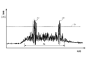
図4は、検査対象物から発せられる異常な振動音の時間変化例を示す波形図である。図4の縦軸は音圧レベルを表し、図4の横軸は時間を表す。振動音が異常である場合、例えば、図4では、図3と同様の区間tpにおいて、音圧レベルが閾値thを超えるような、大きな振動音sdが間欠的(不定期)に発生している。 FIG. 4 is a waveform diagram showing an example of time change of abnormal vibration sound emitted from the inspection object. The vertical axis in FIG. 4 represents the sound pressure level, and the horizontal axis in FIG. 4 represents time. When the vibration sound is abnormal, for example, in FIG. 4, in the same section tp as in FIG. 3, a large vibration sound sd whose sound pressure level exceeds the threshold th is intermittently (irregularly) generated. .
ここでは、異常な振動音として、不定期な異常音、つまり非定常的に起きる異常音を示したが、定常的に大きな音が発生する異常音でも同じである。これらの振動音は、時間軸に対する音圧レベルを表すグラフで表現される。この場合、振動音が閾値を超える大きな音を含むことで、異常音と判定される。また、異常音が特定の周波数成分を含む場合、振動音は、周波数軸に対する音圧レベルを表すグラフで表現される。この場合、音圧が閾値未満であっても、振動音が特定の周波数成分の音を含むことで、異常音と判定される。なお、異常音の判定は、時間軸および周波数軸の一方だけでなく両方に対する音圧レベルを基に、行われてもよい。 Here, as the abnormal vibration sound, an irregular abnormal sound, that is, an abnormal sound that occurs non-stationarily is shown, but the same applies to an abnormal sound that generates a loud steady sound. These vibration sounds are represented by a graph showing the sound pressure level against the time axis. In this case, when the vibration sound includes a loud sound exceeding the threshold, it is determined as an abnormal sound. Moreover, when the abnormal sound includes a specific frequency component, the vibration sound is represented by a graph representing the sound pressure level with respect to the frequency axis. In this case, even if the sound pressure is less than the threshold, the vibrating sound is determined to be an abnormal sound because it includes sound of a specific frequency component. It should be noted that the determination of abnormal sound may be made based on the sound pressure level on not only one of the time axis and the frequency axis, but also on both of them.
(測定時間の算出)
図5は、測定端末10の動作概要例を示す図である。測定端末10のディスプレイ16は、プロセッサ11からの指示に従い、検査対象物ごとの設定情報を設定するための設定画面GM1を表示する。設定画面GM1には、検査スケジュール、異常発生パターン、および異音重要度の3つの選択項目が表示される。検査スケジュールの選択項目では、毎日検査を行うことを表す「毎日」と、所定の日数ごとに検査を行うことを表す「○日に△回」とが選択可能である。「○日に△回」として、例えば「2日に1回」が挙げられる。なお、「3日に1回」、「4日に1回」等が選択可能であってもよい。
(Calculation of measurement time)
FIG. 5 is a diagram showing an example of an outline of the operation of the measuring
異常発生パターンの選択項目では、異音が定常的に発生することを表す「異音が続く」と、異音が非定常的に発生することを表す「異音が不定期に発生」とが選択可能である。 In the selection item of the abnormal occurrence pattern, "abnormal noise continues", which indicates that the abnormal noise occurs constantly, and "abnormal noise occurs irregularly", which indicates that the abnormal noise occurs irregularly. It is selectable.
異音重要度の選択項目では、重要度の高い検査対象物であることを表す「できるだけ早く検査したい」と、重要度の低い検査対象物であることを表す「故障前に検査したい」とが選択可能である。 In the selection items for the degree of importance of abnormal noise, "I want to inspect as soon as possible", which indicates that the inspection object has a high importance, and "I want to inspect it before failure", which indicates that the inspection object has a low importance. It is selectable.
検査員hmは、タッチパネルTPのディスプレイ16に表示された選択項目を指でタッチすることで、上記選択項目を選択可能である。
The inspector hm can select the selection item by touching the selection item displayed on the
プロセッサ11は、タッチパネルTPの入力デバイス17を介して、検査員による設定画面GM1に対する選択操作を受け付けると、検査対象物ごとの設定情報を作成する。プロセッサ11は、メモリ12との協働により実現可能な測定時間算出部11zの機能を有し、作成した設定情報に従い、マイク13で収音し続ける時間である測定時間Tmを算出する。
When the
ディスプレイ16は、プロセッサ11によって点検アプリが起動すると、点検画面GM2を表示する。点検画面GM2には、測定開始ボタンbtが表示される。ディスプレイ16は、プロセッサ11からの指示に従い、測定開始時に収音を促すポップアップ画面pgmを表示する。ポップアップ画面pgmには、例えば「○○秒収音して下さい」のメッセージが表示される。検査員hmは、このメッセージに従い、測定開始ボタンbtを押下すると、マイク13による収音が開始する。
The
図6は、実施の形態1に係る測定端末10の測定時間算出処理の動作手順例を示すフローチャートである。図6の説明の前提として、測定端末10に予めインストールされた測定時間算出アプリケーションは起動済みである。測定時間Tmの算出は、検査対象物ごとに行われる。検査員hmは、測定時間Tmを算出するために、事前に検査対象物となる製品から発せられる振動音をマイク13で収音する。マイク13で振動音が収音されると、プロセッサ11は、振動音の音データをメモリ12に一時記憶する。
FIG. 6 is a flow chart showing an example of the operation procedure of the measurement time calculation process of the measuring
プロセッサ11は、測定時間算出用として、メモリ12に記憶された音データが、定常的に発生している音(つまり、定常音)であるか、それとも、非定常的に発生している音(つまり、不定期音)であるかを判別する(S1)。
The
定常音である場合(S1、定常的)、プロセッサ11は、測定時間Tmを基本時間T0(例えば10秒)に設定する(S2)。基本時間T0は、検査対象物となる製品によらず、固定値であってもよいし、製品ごとに異なる値であってもよい。この後、プロセッサ11は、図6に示す測定時間算出処理を終了する。
If the sound is stationary (S1, steady), the
一方、ステップS1で不定期音である場合(S1、不定期)、プロセッサ11は、測定時間Tmを算出するためのパラメータを算出する。具体的には、プロセッサ11は、検査対象物ごとの設定情報に含まれる検査スケジュールを基に、係数αを算出する(S3)。係数αは、値0~値1の範囲の値であり、一例として、毎日点検を行う場合、値1.0であり、2日に1回点検を行う場合、値0.5である。点検回数が多いほど、係数αは大きな値となる。
On the other hand, if the sound is irregular in step S1 (S1, irregular), the
プロセッサ11は、検査対象物ごとの設定情報に含まれる異常重要度を基に、係数βを算出する(S4)。係数βは、任意な値である。例えば、検査対象物が重要度の高いものであってできるだけ早く検査したい場合、値5が用いられ、検査対象物が重要度のそれほど高いものではなく故障する前に検査できればよいものである場合、値1が用いられる。従って、故障すると悪影響が出るような重要度の高い検査対象物に対しては、速やかにかつ的確に故障箇所の有無を判断して迅速に修理が可能となるように、係数βは、値5と大きな値に設定される。一方、故障してもそれほど悪影響の出ないような重要度の低い検査対象物に対しては、故障前に検査ができればよいので、緊急度が低く、係数βは、値1と小さな値に設定される。
The
プロセッサ11は、係数α,βを用いて、数式(1)に従って測定時間Tmを算出する(S5)。
The
![]()
![]()
数式(1)において、基本時間T0は、ステップS2において定常的な異常音に設定される時間(例えば、10秒)と同じ値に設定される。なお、基本時間T0は、定常的な異常音に設定される時間とは異なる値に設定されてもよい。また、基本時間T0は、固定値(例えば10秒)であったが、検査対象物となる製品ごとに異なる値に設定されてもよい。 In Expression (1), the basic time T0 is set to the same value as the time (for example, 10 seconds) set for the steady abnormal sound in step S2. Note that the basic time T0 may be set to a value different from the time set for the steady abnormal sound. Moreover, although the basic time T0 is a fixed value (for example, 10 seconds), it may be set to a different value for each product to be inspected.
プロセッサ11は、ステップS5において、検査対象物の製品ごとに算出された係数α,βおよび測定時間Tmを、記録装置14に記憶されたパラメータテーブル90に登録する。
The
図7は、パラメータテーブル90の登録内容例を示す表である。パラメータテーブル90は、記録装置14に記憶される。パラメータテーブル90には、検査対象物である製品ごとに、係数α,β、および算出された測定時間Tmが登録される。ここでは、検査対象物である、空調ファン102として、2台の製品AAA,BBCが登録される。コンプレッサ101として、2台の製品KMK,MMMが登録される。ヒートポンプ103として、1台の製品PPPが登録される。例えば、コンプレッサ101の製品AAAの係数α,βおよび測定時間Tmは、それぞれ値1,値5および50秒である。
FIG. 7 is a table showing an example of registered contents of the parameter table 90. As shown in FIG. A parameter table 90 is stored in the
(点検動作)
図8は、実施の形態1に係る測定端末10の点検処理の動作手順例を示すフローチャートである。図8の説明の前提として、測定端末10に予めインストールされた点検アプリケーションは起動済みである。点検を開始する際、検査員hmは、検査対象物に近づき、収音するために測定端末10を検査対象物に向ける。検査員hmが測定端末10のディスプレイ16に表示された測定開始ボタンbtを押下すると、プロセッサ11は、点検動作を開始する。
(Inspection operation)
FIG. 8 is a flow chart showing an example of an operation procedure of inspection processing of the measuring
先ず、プロセッサ11は、マイク13に収音開始を指示し、タイマカウンタ18のカウント動作を開始する。マイク13は、検査対象物から発せられる振動音を含む周囲の音を収音し、音データを生成する(S11)。プロセッサ11は、マイク13から出力される音データをメモリ12に一時記憶する。ここでは、ステップS12で音データを判別するために、測定時間Tmより短い一定時間(例えば10秒)分の音データが記憶される。なお、ステップS19で音データの解析を行うために必要な測定時間Tm分の音データが記憶されてもよい。つまり、プロセッサ11は、解析に必要な時間分の音データを取得した後、ステップS12以降の処理に進むようにしてもよい。
First, the
プロセッサ11は、マイク13で収音された音の音を判別する(S12)。この音の判別では、収音された音が既知の正常音であるか、既知の異常音であるか、未知の音であるかが判別される。この音の判別では、例えば音データのパターンマッチングが行われる。記録装置14には、正常音の音データおよび異常音の音データが登録されている。パターンマッチングの結果、収音された音データと、記録装置14に登録されている音データ(正常音の音データ、異常音の音データを含む)とが一致する場合、既知の音データの音であると判定される。
The
一方、不一致である場合、未知の音データの音であると判定される。未知の音データは、記録装置14に登録されていない音データである。登録されていない音データとして、過去に発生していない異常音、周囲の騒音、風切り音等の音データが挙げられる。なお、この音の判別は、音データが所定時間分(ただし、測定時間Tm未満)蓄積された状態で行われてもよいし、逐次行われてもよい。例えば、音データが特定の周波数成分を含む場合、短時間であっても、既知の音であるか否かを即座に判別可能である。
On the other hand, if they do not match, it is determined to be the sound of unknown sound data. Unknown sound data is sound data that is not registered in the
ステップS12で既知の正常音あるいは既知の異常音であると判別された場合(S12、既知の音)、プロセッサ11は、図6の測定時間算出処理で算出されてパラメータテーブル90に登録された、検査対象物に対応する測定時間Tmを読み出し、タイマカウンタ18にプリセット値としてセットする(S13)。
If it is determined in step S12 that the sound is a known normal sound or a known abnormal sound (S12, known sound), the
一方、ステップS12で未知の音であると判別された場合(S12、未知の音)、プロセッサ11は、プリセット値のカウントを延長済みであるか否かを判別する(S14)。カウント延長済みでない場合(S14、NO)、プロセッサ11は、パラメータテーブル90に登録されている、検査対象物に対応する測定時間Tmを読み出し、この測定時間Tmに延長時間を加えた時間をタイマカウンタ18にプリセット値としてセットする(S15)。一方、カウント延長済みである場合(S14、YES)、プロセッサ11の処理はステップS16に進む。
On the other hand, when it is determined that the sound is unknown in step S12 (S12, unknown sound), the
ステップS13またはステップS15の処理後、プロセッサ11は、タイマカウンタ18のカウントダウンを開始する(S16)。プロセッサ11は、タイマカウンタ18のカウント値が値0に達し、タイマカウンタ18からタイムアップ信号が入力されたか否かを判別する(S17)。カウント値が値0に達していない場合(S17、NO)、つまり測定時間Tmが経過していない場合、プロセッサ11は、ステップS16の処理に戻り、カウント値が値0になるまでマイク13による収音動作を継続する。
After processing in step S13 or step S15, the
一方、ステップS17でカウント値が値0に達した場合(S17、YES)、プロセッサ11は、検査に必要な音データを蓄積できたとして、マイク13による収音動作を終了する(S18)。プロセッサ11は、メモリ12に蓄積された、測定時間Tm分の音データを基に、音データを解析する(S19)。
On the other hand, if the count value reaches 0 in step S17 (S17, YES), the
プロセッサ11は、ステップS18で音データを解析する際、人工知能(AI:Artificial Intelligent)を用いて行う。プロセッサ11は、人工知能を搭載し、予めディープラーニング等の機械学習によって、検査対象物ごとに種々の異常な音データを学習し、学習の結果得られた学習済みモデルを生成しておく。プロセッサ11は、この学習済みモデルに対し、収音された音データを入力し、検査対象物の正常あるいは異常の判定結果を出力させる。異常があった場合、この判定結果は、異常の程度、異常箇所、異常原因等の情報を含んでよい。また、判定結果は、修理の要否、緊急度等の情報を含んでもよい。以上のように、プロセッサ11は、予め機械学習によって生成あるいは更新された学習済みモデルを用いて収音された音データを機械的に解析することにより、測定端末10における検査対象物の異常の有無の判定精度が高まる。なお、学習済みモデルを生成するための機械学習は、1つ以上の統計的分類技術を用いて行っても良い。統計的分類技術としては、例えば、線形分類器(linear classifiers)、サポートベクターマシン(support vector machines)、二次分類器(quadratic classifiers)、カーネル密度推定(kernel estimation)、決定木(decision trees)、人工ニューラルネットワーク(artificial neural networks)、ベイジアン技術および/またはネットワーク(Bayesian techniques and/or networks)、隠れマルコフモデル(hidden Markov models)、バイナリ分類子(binary classifiers)、マルチクラス分類器(multi-class classifiers)クラスタリング(a clustering technique)、ランダムフォレスト(a random forest technique)、ロジスティック回帰(a logistic regression technique)、線形回帰(a linear regression technique)、勾配ブースティング(a gradient boosting technique)等が挙げられる。ただし、使用される統計的分類技術はこれらに限定されない。
The
なお、ステップS19における音データの解析では、人工知能を用いる代わりに、ステップS12と同様、音データのパターンマッチングが行われてもよい。ただし、ステップS12で行われた音データの判別と比べ、ステップS19における音データのパターンマッチングは、より詳細に行われる。例えば、記録装置14には、音データの判別に用いられる正常音および異常音の音データに比べ、より膨大な音データが登録されている。ステップS18における音データのパターンマッチングでは、これらの膨大な音データと収音された音データとが比較される。従って、検査対象物の異常の有無を正確かつ詳細に判定可能である。
In the analysis of sound data in step S19, instead of using artificial intelligence, pattern matching of sound data may be performed as in step S12. However, the pattern matching of the sound data in step S19 is performed in more detail than the sound data discrimination performed in step S12. For example, in the
プロセッサ11は、検査対象物の異常の有無の判定結果をディスプレイ16に表示する(S20)。検査員は、ディスプレイ16に表示された、異常の有無の判定結果を視認する。この後、プロセッサ11は、図8に示す点検処理を終了する。
The
以上により、実施の形態1に係る測定端末10あるいは測定端末10による測定方法によれば、マイク13(取得部の一例)は、検査対象物から発せられる振動音を含む周囲の音を収音し、音データを生成する(つまり、取得する)。メモリ12は、検査対象物の検査スケジュールに基づく係数αおよび異常重度度に基づく係数β(検査および異常の特徴に関するパラメータの一例)を含む設定情報を検査対象物ごとに記憶(つまり、保持)する。プロセッサ11(導出部の一例)は、検査対象物に対応する設定情報に基づいて、検査対象物の異常の有無を判定するために用いる測定時間Tm(検査対象物からの音データを取得するための所要時間の一例)を算出(つまり、導出)する。プロセッサ11(解析部の一例)は、算出された測定時間Tm分の検査対象物からの音データに基づいて、検査対象物の異常の有無を判定する。
As described above, according to the
これにより、実施の形態1に係る測定端末10は、検査対象物ごとの検査および異常のそれぞれのパラメータ等の特徴を考慮して、異常の有無を判定するための測定データの適切な測定時間を導出し、異常の有無の迅速かつ効率的な判定を支援することができる。
As a result, the
また、プロセッサ11(制御部の一例)は、算出された測定時間Tm分(所要時間分の一例)の検査対象物からの音データの取得を促す表示をディスプレイ16に表示する。この音データの取得を促す表示の処理は、例えば、測定端末10において検査対象物の異常の有無が判定されるよりも先立って実行される。これにより、検査員hmは、測定開始のタイミンクを視覚的かつ簡易に把握できる。
In addition, the processor 11 (an example of the control unit) displays on the display 16 a display prompting acquisition of sound data from the inspection target for the calculated measurement time Tm (an example of the required time). This process of display prompting acquisition of sound data is executed, for example, before the
また、設定情報は、検査対象物の検査スケジュールと、検査対象物の異常の発生パターンと、検査対象物の異常の発生に関する重要度とを含む。これにより、測定端末10は、検査対象物の動作状態に合わせて、適切な測定時間を算出できる。
The setting information also includes an inspection schedule of the inspection object, an occurrence pattern of anomalies in the inspection object, and a degree of importance regarding occurrence of anomalies in the inspection object. Thereby, the
また、プロセッサ11は、検査対象物からの音データを逐次入力し、算出された測定時間Tm分の検査対象物からの音データを入力した場合に、測定時間Tm分の音データに基づく異常の有無の判定結果をディスプレイ16に表示する。これにより、検査員hmは、検査対象物の異常の有無を視覚的に把握できる。
Further, the
また、測定端末10は、検査員hm(ユーザ)が携帯可能である。これにより、検査員hmが、建物に設置された、複数の検査対象物(空調ファン、コンプレッサ等)を巡回して検査する際、検査対象物が設置された場所に容易に移動できる。また、検査員hmは、測定端末10を操作し易い。
Also, the measuring
また、記録装置14(メモリの一例)は、算出された検査対象物ごとの測定時間Tmを記憶(つまり、保持)する。このように、一度、測定端末10は、算出した測定時間を検査対象物ごとに記録装置に登録しておくことで、検査対象物を点検する際、登録された測定時間を読み出して使用することができる。従って、測定端末10は、検査対象物を点検する度に、測定時間を算出する手間を省くことができ、検査員の作業効率を改善できる。
In addition, the recording device 14 (an example of a memory) stores (that is, retains) the calculated measurement time Tm for each inspection object. In this way, once the measuring
また、プロセッサ11は、異常無しであると判定された正常音の音データと、異常有りと判定された異常音の音データとを予め記録装置14に登録するとともに、マイク13で逐次入力された(つまり、逐次収音された)音の音データが記録装置14に登録された正常音の音データおよび異常音の音データのいずれとも不一致である場合、マイク13で音が収音される測定時間Tmを延長する。これにより、測定端末10は、検査対象物から測定端末10が登録していない音データ(つまり、未知の音データ)を入力した場合でも、測定時間Tmを延長することで、登録されている正常音の音データおよび異常音の音データのパターンに一致した音データを検知できる可能性が高まり、未知の音データにも効率的に対処できる。
In addition, the
また、プロセッサ11は、マイク13で収音された異常音の出現頻度に応じて、測定時間Tmの長さを伸縮させるように所要時間を導出する。これにより、測定端末10は、検査対象物の異常音の出現頻度が多く、故障に至る可能性が高いと判断される場合、測定時間を延長して振動音の音データを生成できる。また、測定端末10は、収音された振動音の音データを基に、検査対象物の異常の有無を正確に判定できる。一方、検査対象物の異常音の出現頻度が少なく、故障に至る可能性が低いと想定される場合、測定端末10は、測定時間を短縮して検査を効率化できる。
In addition, the
また、プロセッサ11は、予め機械学習(例えば、上述した統計的分類技術を用いた機械学習)によって生成あるいは更新されて測定端末10に保存(保持)された学習済みモデルを用いて、マイク13により収音された音データを機械的に解析することにより、検査対象物の異常の有無を判定する。これにより、測定端末10は、検査対象物の異常の有無の判定精度を高めることができる。
In addition, the
(第1変形例)
第1変形例においても測定端末10の構成は実施の形態1に係る測定端末10と同一であるため、重複する内容の説明は簡略化または省略し、異なる内容について説明する。
(First modification)
In the first modification, the configuration of the measuring
上述した実施の形態1では、基本時間T0に対し、検査スケジュールに基づく係数αと、異常重要度に基づく係数βとを乗算することによって、測定時間Tmが算出された。第1変形例では、不定期に発生する異常音の出現頻度が予め分かっている場合、出現頻度に対応する係数γを設定し、この係数γを加味し、式(2)に従って、測定時間Tmを算出する。
In
![]()
![]()
これにより、測定端末10は、異常音の出現頻度に応じて、測定時間の長短を決定できる。例えば、検査対象物の異常音の出現頻度が多い場合、係数γを大きな値に設定し、一方、検査対象物の異常音の出現頻度が少ない場合、係数γを小さい値に設定してもよい。出現頻度の高い異常音に対しては、故障に至る蓋然性が高いとし、収音時間を長くして正確に音データを解析できるようにする。一方、出現頻度の低い異常音に対しては、すぐに故障する心配は少ないと判断し、測定時間を短くする。
Thereby, the
逆に、検査対象物の異常音の出現頻度が多い場合、係数γを小さい値に設定し、一方、出現頻度が少ない場合、係数γを大きな値に設定してもよい。出現頻度の高い異常音に対しては、収音時間が短くても異常音の音データを収音できる。一方、出現頻度の低い異常音に対しては、異常音の音データを収音できる確率が高くなる。 Conversely, the coefficient γ may be set to a small value when the frequency of appearance of abnormal sounds in the inspection object is high, and the coefficient γ may be set to a large value when the frequency of appearance is low. For an abnormal sound that appears frequently, the sound data of the abnormal sound can be collected even if the sound collection time is short. On the other hand, for an abnormal sound with a low appearance frequency, the probability that the sound data of the abnormal sound can be collected increases.
(第2変形例)
上述した実施の形態1では、測定端末が検査対象物から発せられる音を収音して音データを解析し、音データを基に検査対象物の異常の有無を判定した。第2変形例では、外部装置であるクラウドサーバが測定端末で収音された音の音データを解析し、音データを基に検査対象物の異常の有無を判定する場合を示す。
(Second modification)
In the first embodiment described above, the measurement terminal collects the sound emitted from the inspection object, analyzes the sound data, and determines whether or not there is an abnormality in the inspection object based on the sound data. In the second modification, a cloud server, which is an external device, analyzes sound data of sound collected by the measurement terminal, and determines whether or not there is an abnormality in the inspection object based on the sound data.
第2変形例においても測定端末10の構成は実施の形態1に係る測定端末10と同一であるため、重複する内容の説明は簡略化または省略し、異なる内容について説明する。
In the second modification, the configuration of the measuring
第2変形例において、クラウドサーバ40は、実施の形態1に係る測定端末10のように、測定端末10のマイク13により収音された検査対象物の音データを測定端末10から受信して取得する。クラウドサーバ40は、受信された検査対象物の音データを解析することにより、検査対象物の異常の有無を判定し、判定結果を測定端末10に送信する。
In the second modification, the
クラウドサーバ40は、プロセッサ41と、メモリ42と、記録装置44と、通信回路45とを含む構成である。
The
プロセッサ41は、検査員hmが検査対象物を点検する際、測定端末10における測定時間算出アプリケーションの実行中にマイク13が収音するための音の測定時間を算出する。また、プロセッサ41は、測定端末10が点検アプリケーションを実行中に、測定端末10から送信されてくる検査対象物の音データを用いて、検査対象物の点検動作を行う。プロセッサ41は、例えば、CPU(Central Processing Unit),MPU(Micro Processor Unit),DSP(Digital Signal Processor)あるいはFPGA(Field Programmable Gate Array)等が用いられる。
The
メモリ42は、RAM(Random Access Memory)を有し、通信回路45において受信された検査対象物の音データを一時記憶する。メモリ42は、ROM(Read Only Memory)を有し、プロセッサ41の処理を規定するためのプログラムおよびデータを格納する。
The
記録装置44(メモリの一例)は、測定端末10により収音された音データと比較される、正常な音データおよび異常な音データをそれぞれ記憶する。記録装置44は、検査対象物ごとに異なるパラメータおよび測定時間がそれぞれ登録されたパラメータテーブル90を記憶する。記録装置44は、例えばSSD(Solid State Drive)、HDD(Hard Disk Drive)、書き換え可能なROM(例えばEEPROM:Electrically Erasable Programmable Read-Only Memory)等で構成される。
The recording device 44 (an example of memory) stores normal sound data and abnormal sound data to be compared with the sound data picked up by the measuring
通信回路45は、例えば無線LAN(Local Area Network)、モバイル通信網(例えば4G(第4世代移動通信システム)、5G(第5世代移動通信システム)等のセルラネットワーク網)を介して、ネットワークNWに接続され、測定端末10あるいはストレージ50との間で通信可能である。
The
図9は、変形例2における音検査システム5の動作手順を示すシーケンス図である。図9の説明の前提として、測定端末10に予めインストールされた点検アプリケーションは起動済みである。クラウドサーバ40は、測定端末10から音データを受信するまで待つ、待機状態にある(T1)。点検を開始する際、検査員は、検査対象物に近寄り、測定端末10を検査対象物に向ける。検査員が測定端末10のディスプレイ16に表示された測定開始ボタンbtを押下すると、測定端末10は、検査対象物から発せられる振動音を含む周囲の音をマイク13で収音し、音データを逐次生成する(T2)。
FIG. 9 is a sequence diagram showing the operation procedure of the
測定端末10は、逐次生成した音データを、通信回路15およびネットワークNWを介して、クラウドサーバ40に送信する(T3)。クラウドサーバ40は、測定端末10から送信された音データを受信し、内部メモリ(図示略)に蓄積する(T4)。
The
測定端末10は、タイマカウンタ18が値0になり、測定時間Tmが経過したか否かを判別する(T5)。タイマカウンタ18が値0でない場合、測定端末10は、手順T2に戻り、マイク13による収音動作を継続する。
The measuring
手順T5でタイマカウンタ18が値0になると、測定端末10は、通信回路15およびネットワークNWを介して、クラウドサーバ40に解析指示を送信する(T6)。クラウドサーバ40は、ネットワークNWを介して、測定端末10からの解析指示を受信すると、内部メモリに蓄積した測定時間Tm分の音データを解析する(T7)。この解析は、上記実施形態のステップS19において、測定端末10が行った解析と同じであってもよいし、より詳細な解析であってもよい。例えば、人工知能を用いて解析を行う場合、クラウドサーバ40によって生成された学習済みモデルでは、測定端末10と比べ、ストレージ50に蓄積された音データを用いてもよく、学習量が膨大であると想定されるので、生成される学習済みモデルは処理精度の高いものとなる。従って、測定端末10により収音された音データをクラウドサーバ40で解析することで、クラウドサーバ40における検査対象物の異常の有無の判定精度が高まる。なお、学習済みモデルを生成するための機械学習は、1つ以上の統計的分類技術を用いて行っても良い。統計的分類技術としては、例えば、線形分類器(linear classifiers)、サポートベクターマシン(support vector machines)、二次分類器(quadratic classifiers)、カーネル密度推定(kernel estimation)、決定木(decision trees)、人工ニューラルネットワーク(artificial neural networks)、ベイジアン技術および/またはネットワーク(Bayesian techniques and/or networks)、隠れマルコフモデル(hidden Markov models)、バイナリ分類子(binary classifiers)、マルチクラス分類器(multi-class classifiers)クラスタリング(a clustering technique)、ランダムフォレスト(a random forest technique)、ロジスティック回帰(a logistic regression technique)、線形回帰(a linear regression technique)、勾配ブースティング(a gradient boosting technique)等が挙げられる。ただし、使用される統計的分類技術はこれらに限定されない。
When the
クラウドサーバ40は、ネットワークNWを介して、この解析結果を測定端末10に送信する(T8)。測定端末10は、通信回路15およびネットワークNWを介して、クラウドサーバ40からの解析結果を受信する(T9)。解析結果には、音データに基づく検査対象物の異常の有無の判定結果が含まれる。測定端末10は、ディスプレイ16にこの判定結果を表示する(T10)。検査員は、ディスプレイ16に表示された、検査対象物の異常の有無の判定結果を把握し、次の検査対象物に移動する。
The
以上により、第2変形例に係る音検査システム5(測定システムの一例)では、測定端末10は、検査対象物からの音データを取得するプロセッサ11(取得部の一例)と、取得された検査対象物からの音データおよび音データの解析指示を送信し、検査対象物からの音データに基づく異常の有無の判定結果を受信する通信回路15(第1の通信部の一例)と、を備え、その受信された判定結果をディスプレイ16に表示する。クラウドサーバ40(解析装置の一例)は、検査対象物からの音データおよび解析指示を測定端末10より受信し、判定結果を測定端末10に送信する通信回路45(第2の通信部の一例)を備える。クラウドサーバ40では、メモリ42は、検査対象物の検査および異常の特徴に関するパラメータを含む設定情報を検査対象物ごとに保持する。プロセッサ41(導出部の一例)は、検査対象物に対応する設定情報に基づいて、検査対象物の異常の有無を判定するために用いる検査対象物からの音データを取得するための所要時間を導出する。プロセッサ41(解析部の一例)は、導出された所要時間分の検査対象物からの音データに基づいて、検査対象物の異常の有無を判定する。
As described above, in the sound inspection system 5 (an example of the measurement system) according to the second modification, the
このように、クラウドサーバ40が音データを解析することで、測定端末10が音データの解析を行う場合に比べて、より詳細かつ高精度に行うことが可能である。従って、検査員hmは、検査対象物の異常の有無の判定に対し、精度の高い判定結果を得ることができる。また、測定端末10が解析処理を行わなくて済むので、測定端末10による処理の負担を軽減でき、測定端末10を簡易かつ安価な機器として提供できる。
As described above, the
また、クラウドサーバ40では、プロセッサ41は、予め機械学習(例えば、上述した統計的分類技術を用いた機械学習)によって生成あるいは更新されてクラウドサーバ40に保存(保持)された学習済みモデルを用いて、測定端末10のマイク13により収音された音データを機械的かつ高精度に解析することにより、検査対象物の異常の有無を判定する。これにより、クラウドサーバ40は、検査対象物の異常の有無の判定精度を、測定端末10が検査対象物の異常の有無を判定する場合に比べてより高めることができる。
Further, in the
以上、図面を参照しながら各種の実施の形態について説明したが、本開示はかかる例に限定されないことは言うまでもない。当業者であれば、特許請求の範囲に記載された範疇内において、各種の変更例、修正例、置換例、付加例、削除例、均等例に想到し得ることは明らかであり、それらについても当然に本開示の技術的範囲に属するものと了解される。また、発明の趣旨を逸脱しない範囲において、上述した各種の実施の形態における各構成要素を任意に組み合わせてもよい。 Various embodiments have been described above with reference to the drawings, but it goes without saying that the present disclosure is not limited to such examples. It is obvious that a person skilled in the art can conceive of various modifications, modifications, substitutions, additions, deletions, and equivalents within the scope of the claims. Naturally, it is understood that it belongs to the technical scope of the present disclosure. In addition, the constituent elements of the various embodiments described above may be combined arbitrarily without departing from the gist of the invention.
例えば、測定端末10は、検査員hmが携帯可能なスマートフォン、タブレット端末、ノートPC等の装置であることが望ましいが、台車等に載せられて移動可能な可搬型の装置であってもよい。
For example, the
また、本開示は、上述した実施の形態に係る測定端末10の機能を実現するプログラムを、ネットワークあるいは各種記憶媒体を介してコンピュータである測定端末に供給し、この測定端末のプロセッサが読み出して実行するプログラム、およびこのプログラムが記憶された記録媒体も適用範囲である。また、本開示は、上述した実施の形態に係る音検査システム5のクラウドサーバ40の機能を実現するプログラムを、ネットワークあるいは各種記憶媒体を介してコンピュータであるクラウドサーバ40に供給し、このクラウドサーバ40のプロセッサ41が読み出して実行するプログラム、およびこのプログラムが記憶された記録媒体も適用範囲としてよい。
Further, according to the present disclosure, a program that realizes the functions of the measuring
本開示は、検査対象物の異常の有無を判定するための測定データの適切な測定時間を導出し、異常の有無の迅速かつ効率的な判定を支援することができる測定端末、測定方法およびプログラムとして有用である。 The present disclosure is a measurement terminal, a measurement method, and a program that can derive an appropriate measurement time for measurement data for determining the presence or absence of an abnormality in an inspection object, and support quick and efficient determination of the presence or absence of an abnormality. is useful as
5 音検査システム
10 測定端末
11 プロセッサ
12 メモリ
13 マイク
14 記録装置
15 通信回路
16 ディスプレイ
17 入力デバイス
18 タイマカウンタ
40 クラウドサーバ
50 ストレージ
TP タッチパネル
5
Claims (19)
前記検査対象物の検査および音データの特徴に関するパラメータを含む設定情報を前記検査対象物ごとに保持するメモリと、
前記設定情報に基づいて、前記検査対象物の前記検査に要する前記検査対象物の音データの取得時間を導出する導出部と、
前記導出された取得時間分の前記検査対象物の音データに基づいて、前記検査対象物の異常の有無を判定する解析部と、を備え、
前記設定情報は、前記検査対象物の検査スケジュールと、前記検査対象物の異常の発生パターンと、前記検査対象物の異常の発生に関する重要度とを含む、
測定端末。 an acquisition unit that acquires sound data from an object to be inspected;
a memory for holding, for each inspection object, setting information including parameters relating to inspection of the inspection object and characteristics of sound data;
a derivation unit that derives an acquisition time of the sound data of the inspection object required for the inspection of the inspection object, based on the setting information;
an analysis unit that determines the presence or absence of an abnormality in the inspection object based on the derived sound data of the inspection object for the acquisition time ,
The setting information includes an inspection schedule of the inspection object, an abnormality occurrence pattern of the inspection object, and a degree of importance related to the occurrence of an abnormality of the inspection object .
measuring terminal.
請求項1に記載の測定端末。 The derivation unit determines an occurrence pattern of sound data of the inspection object, and derives the acquisition time by a different method depending on the result of the determination.
The measuring terminal according to claim 1.
請求項1に記載の測定端末。 a control unit that displays on a display an indication prompting acquisition of sound data from the inspection object for the derived acquisition time,
The measuring terminal according to claim 1.
請求項1に記載の測定端末。 The analysis unit sequentially inputs the sound data from the inspection object, and when inputting the sound data from the inspection object for the derived acquisition time, the analysis unit based on the sound data for the acquisition time Display the judgment result of the presence or absence of abnormality on the display,
The measuring terminal according to claim 1 .
請求項1に記載の測定端末。 The analysis unit registers sound data of a normal sound determined as having no abnormality and sound data of an abnormal sound determined as having an abnormality in the memory, and the sound data sequentially input to the acquisition unit. is inconsistent with both the sound data of the normal sound and the sound data of the abnormal sound, extending the derived acquisition time.
The measuring terminal according to claim 1 .
請求項1に記載の測定端末。 The derivation unit derives the acquisition time so that the length of the acquisition time is extended or shortened according to the frequency of appearance of the sound data of the abnormal sound acquired by the acquisition unit.
The measuring terminal according to claim 1 .
請求項1に記載の測定端末。 The analysis unit determines the presence or absence of an abnormality in the inspection object using a learned model generated in advance by machine learning.
The measuring terminal according to claim 1 .
前記検査対象物からの音データおよび前記解析指示を前記測定端末より受信する第2の通信部を備える解析装置と、により構成される測定システムであって、
前記解析装置は、さらに、
前記検査対象物の検査および音データの特徴に関するパラメータを含む設定情報を前記検査対象物ごとに保持するメモリと、
前記設定情報に基づいて、前記検査対象物の前記検査に要する前記検査対象物の音データの取得時間を導出する導出部と、
前記導出された取得時間分の前記検査対象物の音データに基づいて、前記検査対象物の異常の有無を判定する解析部と、を備え、
前記設定情報は、前記検査対象物の検査スケジュールと、前記検査対象物の異常の発生パターンと、前記検査対象物の異常の発生に関する重要度とを含む、
測定システム。 A measurement terminal comprising: an acquisition unit that acquires sound data from an inspection object; and a first communication unit that transmits the acquired sound data from the inspection object and an analysis instruction for the sound data;
an analysis device comprising a second communication unit that receives sound data from the inspection object and the analysis instruction from the measurement terminal,
The analysis device further
a memory for holding, for each inspection object, setting information including parameters relating to inspection of the inspection object and characteristics of sound data;
a derivation unit that derives an acquisition time of the sound data of the inspection object required for the inspection of the inspection object, based on the setting information;
an analysis unit that determines the presence or absence of an abnormality in the inspection object based on the derived sound data of the inspection object for the acquisition time ,
The setting information includes an inspection schedule of the inspection object, an abnormality occurrence pattern of the inspection object, and a degree of importance related to the occurrence of an abnormality of the inspection object .
measurement system.
前記測定端末は、前記解析装置から送信された前記判定結果を前記第1の通信部によって受信し、前記判定結果をディスプレイに表示し、
前記解析部は、予め機械学習によって生成された学習済みモデルを用いて前記検査対象物の異常の有無を判定する、
請求項8に記載の測定システム。 The analysis device further comprises an analysis unit that determines whether or not there is an abnormality in the inspection object based on the derived sound data from the inspection object for the acquisition time. transmitting the determination result of the presence or absence of the abnormality based on the second communication unit to the measurement terminal;
The measurement terminal receives the determination result transmitted from the analysis device by the first communication unit, displays the determination result on a display,
The analysis unit determines the presence or absence of an abnormality in the inspection object using a learned model generated in advance by machine learning.
A measurement system according to claim 8 .
前記検査対象物の検査および音データの特徴に関するパラメータを含む設定情報を前記検査対象物ごとにメモリに保持するステップと、
前記設定情報に基づいて、前記検査対象物の前記検査に要する前記検査対象物の音データの取得時間を導出するステップと、
前記導出された取得時間分の前記検査対象物の音データに基づいて、前記検査対象物の異常の有無を判定するステップと、を有し、
前記設定情報は、前記検査対象物の検査スケジュールと、前記検査対象物の異常の発生パターンと、前記検査対象物の異常の発生に関する重要度とを含む、
測定方法。 obtaining sound data from an object to be inspected;
a step of holding setting information including parameters relating to inspection of the inspection object and features of sound data in a memory for each inspection object;
a step of deriving an acquisition time of the sound data of the inspection object required for the inspection of the inspection object, based on the setting information;
determining whether or not there is an abnormality in the inspection object based on the derived sound data of the inspection object for the acquisition time ;
The setting information includes an inspection schedule of the inspection object, an abnormality occurrence pattern of the inspection object, and a degree of importance related to the occurrence of an abnormality of the inspection object .
Measuring method.
請求項10に記載の測定方法。 further comprising, prior to the step of determining the presence or absence of an abnormality in the inspection object, displaying on a display a display prompting acquisition of sound data from the inspection object for the derived acquisition time;
The measuring method according to claim 10 .
請求項10に記載の測定方法。 The step of determining whether or not there is an abnormality in the inspection object includes sequentially inputting sound data from the inspection object, and when inputting sound data from the inspection object for the derived acquisition time, including the step of displaying on a display the determination result of the presence or absence of the abnormality based on the sound data for the acquisition time;
The measuring method according to claim 10 .
請求項10に記載の測定方法。 In the step of determining whether or not there is an abnormality in the inspection object, sound data of a normal sound determined to be free of abnormality and sound data of an abnormal sound determined to be abnormal are registered in the memory, and sequentially extending the derived acquisition time if input sound data does not match both the normal sound sound data and the abnormal sound sound data.
The measuring method according to claim 10 .
請求項10に記載の測定方法。 The step of deriving the acquisition time derives the acquisition time so that the length of the acquisition time is expanded or contracted according to the frequency of appearance of the sound data of the acquired abnormal sound.
The measuring method according to claim 10 .
請求項10に記載の測定方法。 The step of determining the presence or absence of an abnormality in the inspection object includes determining the presence or absence of an abnormality in the inspection object using a learned model generated in advance by machine learning.
The measuring method according to claim 10 .
検査対象物からの音データを取得するステップと、
前記検査対象物の検査および音データの特徴に関するパラメータを含む設定情報を前記検査対象物ごとにメモリに保持するステップと、
前記設定情報に基づいて、前記検査対象物の前記検査に要する前記検査対象物の音データの取得時間を導出するステップと、
前記導出された取得時間分の前記検査対象物の音データに基づいて、前記検査対象物の異常の有無を判定するステップと、を実行させ、
前記設定情報は、前記検査対象物の検査スケジュールと、前記検査対象物の異常の発生パターンと、前記検査対象物の異常の発生に関する重要度とを含む、
プログラム。 The measurement terminal, which is a computer,
obtaining sound data from an object to be inspected;
a step of holding setting information including parameters relating to inspection of the inspection object and features of sound data in a memory for each inspection object;
a step of deriving an acquisition time of the sound data of the inspection object required for the inspection of the inspection object, based on the setting information;
determining whether or not there is an abnormality in the inspection object based on the derived sound data of the inspection object for the acquisition time ;
The setting information includes an inspection schedule of the inspection object, an abnormality occurrence pattern of the inspection object, and a degree of importance related to the occurrence of an abnormality of the inspection object.
program.
前記検査対象物の異常の有無を判定するステップと、を、前記測定端末に保持される、予め機械学習によって生成された学習済みモデルを用いて実行させる、
請求項16に記載のプログラム。 a step of determining whether or not there is an abnormality in the inspection object based on the derived sound data of the inspection object for the acquisition time in the measurement terminal;
and a step of determining whether or not there is an abnormality in the inspection object using a learned model generated in advance by machine learning and held in the measurement terminal.
17. A program according to claim 16 .
前記検査対象物からの音データおよび前記音データの解析指示を前記測定端末より受信するステップと、
前記検査対象物の検査および音データの特徴に関するパラメータを含む設定情報を前記検査対象物ごとにメモリに保持するステップと、
前記設定情報に基づいて、前記検査対象物の前記検査に要する前記検査対象物の音データの取得時間を導出するステップと、
前記導出された取得時間分の前記検査対象物の音データに基づいて、前記検査対象物の異常の有無を判定するステップと、を実行させ、
前記設定情報は、前記検査対象物の検査スケジュールと、前記検査対象物の異常の発生パターンと、前記検査対象物の異常の発生に関する重要度とを含む、
プログラム。 An analysis device, which is a computer, which constitutes a measurement system together with a measurement terminal which acquires sound data from an object to be inspected and transmits the acquired sound data from the object to be inspected and an instruction to analyze the sound data. to the
a step of receiving sound data from the inspection object and an instruction to analyze the sound data from the measurement terminal;
a step of holding setting information including parameters relating to inspection of the inspection object and features of sound data in a memory for each inspection object;
a step of deriving an acquisition time of the sound data of the inspection object required for the inspection of the inspection object, based on the setting information;
determining whether or not there is an abnormality in the inspection object based on the derived sound data of the inspection object for the acquisition time ;
The setting information includes an inspection schedule of the inspection object, an abnormality occurrence pattern of the inspection object, and a degree of importance related to the occurrence of an abnormality of the inspection object.
program.
前記導出された取得時間分の前記検査対象物からの音データに基づいて、前記検査対象物の異常の有無を判定するステップと、
前記取得時間分の音データに基づく前記異常の有無の判定結果を前記測定端末に送信するステップと、をさらに実行させ、
前記検査対象物の異常の有無を判定するステップを、前記解析装置に保持される、予め機械学習によって生成された学習済みモデルを用いて実行させる、
請求項18に記載のプログラム。 to the analysis device,
a step of determining whether or not there is an abnormality in the inspection object based on the derived sound data from the inspection object for the acquisition time;
further executing a step of transmitting to the measurement terminal a determination result of the presence or absence of the abnormality based on the sound data for the acquisition time;
causing the step of determining the presence or absence of an abnormality in the inspection object to be performed using a learned model generated in advance by machine learning and held in the analysis device;
19. A program according to claim 18 .
Priority Applications (5)
| Application Number | Priority Date | Filing Date | Title |
|---|---|---|---|
| JP2018121556A JP7129647B2 (en) | 2018-06-27 | 2018-06-27 | Measuring terminal, measuring system, measuring method and program |
| CN201980056209.0A CN112639420B (en) | 2018-06-27 | 2019-03-13 | Measurement terminal, measurement system, measurement method, and program |
| PCT/JP2019/010422 WO2020003635A1 (en) | 2018-06-27 | 2019-03-13 | Measurement terminal, measurement system, measurement method, and program |
| US17/255,279 US11629993B2 (en) | 2018-06-27 | 2019-03-13 | Measurement terminal, measurement system, measurement method, and program |
| JP2022127946A JP7442102B2 (en) | 2018-06-27 | 2022-08-10 | Measuring terminal, measuring system, measuring method and program |
Applications Claiming Priority (1)
| Application Number | Priority Date | Filing Date | Title |
|---|---|---|---|
| JP2018121556A JP7129647B2 (en) | 2018-06-27 | 2018-06-27 | Measuring terminal, measuring system, measuring method and program |
Related Child Applications (1)
| Application Number | Title | Priority Date | Filing Date |
|---|---|---|---|
| JP2022127946A Division JP7442102B2 (en) | 2018-06-27 | 2022-08-10 | Measuring terminal, measuring system, measuring method and program |
Publications (3)
| Publication Number | Publication Date |
|---|---|
| JP2020003282A JP2020003282A (en) | 2020-01-09 |
| JP2020003282A5 JP2020003282A5 (en) | 2021-07-26 |
| JP7129647B2 true JP7129647B2 (en) | 2022-09-02 |
Family
ID=68986925
Family Applications (2)
| Application Number | Title | Priority Date | Filing Date |
|---|---|---|---|
| JP2018121556A Active JP7129647B2 (en) | 2018-06-27 | 2018-06-27 | Measuring terminal, measuring system, measuring method and program |
| JP2022127946A Active JP7442102B2 (en) | 2018-06-27 | 2022-08-10 | Measuring terminal, measuring system, measuring method and program |
Family Applications After (1)
| Application Number | Title | Priority Date | Filing Date |
|---|---|---|---|
| JP2022127946A Active JP7442102B2 (en) | 2018-06-27 | 2022-08-10 | Measuring terminal, measuring system, measuring method and program |
Country Status (4)
| Country | Link |
|---|---|
| US (1) | US11629993B2 (en) |
| JP (2) | JP7129647B2 (en) |
| CN (1) | CN112639420B (en) |
| WO (1) | WO2020003635A1 (en) |
Families Citing this family (1)
| Publication number | Priority date | Publication date | Assignee | Title |
|---|---|---|---|---|
| JP7129647B2 (en) * | 2018-06-27 | 2022-09-02 | パナソニックIpマネジメント株式会社 | Measuring terminal, measuring system, measuring method and program |
Citations (4)
| Publication number | Priority date | Publication date | Assignee | Title |
|---|---|---|---|---|
| JP2002181038A (en) | 2000-12-18 | 2002-06-26 | Mitsubishi Heavy Ind Ltd | Abnormality diagnosis device |
| JP2004361286A (en) | 2003-06-05 | 2004-12-24 | Nittetsu Yahata Eng Kk | Method of diagnosing deterioration of rotary machine |
| JP2012078288A (en) | 2010-10-05 | 2012-04-19 | Asahi Kasei Engineering Kk | Method for diagnosing roller bearing |
| JP2015114214A (en) | 2013-12-12 | 2015-06-22 | Ntn株式会社 | Mobile terminal-utilizing checkup system, and checkup method, for rotary machine components |
Family Cites Families (14)
| Publication number | Priority date | Publication date | Assignee | Title |
|---|---|---|---|---|
| JPS5850397B2 (en) * | 1976-04-23 | 1983-11-10 | 三菱電機株式会社 | Signal determination device that determines abnormal signals, etc. |
| JPS58108419A (en) * | 1981-12-23 | 1983-06-28 | Toshiba Corp | Abnormality inspection apparatus |
| JP3075564B2 (en) * | 1990-04-06 | 2000-08-14 | 株式会社日立製作所 | Pipe thinning management evaluation system |
| JP3450061B2 (en) * | 1994-10-25 | 2003-09-22 | 光洋精工株式会社 | Bearing diagnosis system |
| JP3484665B2 (en) | 1997-12-15 | 2004-01-06 | オムロン株式会社 | Abnormality determination method and device |
| JPH11326035A (en) * | 1998-05-19 | 1999-11-26 | Ono Sokki Co Ltd | Vibration comparator |
| JP4078671B2 (en) | 2003-12-17 | 2008-04-23 | 株式会社日立製作所 | Plant maintenance management method |
| JP2008232934A (en) | 2007-03-22 | 2008-10-02 | Jfe Advantech Co Ltd | Facility diagnosis system |
| JP2009180648A (en) | 2008-01-31 | 2009-08-13 | Hitachi-Ge Nuclear Energy Ltd | Sensor node, sensor network system, and oscillation measuring method |
| CN101614583B (en) * | 2009-04-30 | 2011-06-22 | 上海电力学院 | Plugging material detection early warning device and method based on voice recognition |
| JP5460160B2 (en) | 2009-07-22 | 2014-04-02 | Jfeメカニカル株式会社 | Equipment diagnostic equipment |
| CN102243143B (en) * | 2011-04-20 | 2014-04-30 | 上海斐赛轴承科技有限公司 | Bearing abnormal sound detection control method and bearing vibration measuring instrument |
| WO2015087732A1 (en) | 2013-12-12 | 2015-06-18 | Ntn株式会社 | Method and system for inspecting rotary machine component by using portal terminal |
| JP7129647B2 (en) | 2018-06-27 | 2022-09-02 | パナソニックIpマネジメント株式会社 | Measuring terminal, measuring system, measuring method and program |
-
2018
- 2018-06-27 JP JP2018121556A patent/JP7129647B2/en active Active
-
2019
- 2019-03-13 CN CN201980056209.0A patent/CN112639420B/en active Active
- 2019-03-13 WO PCT/JP2019/010422 patent/WO2020003635A1/en active Application Filing
- 2019-03-13 US US17/255,279 patent/US11629993B2/en active Active
-
2022
- 2022-08-10 JP JP2022127946A patent/JP7442102B2/en active Active
Patent Citations (4)
| Publication number | Priority date | Publication date | Assignee | Title |
|---|---|---|---|---|
| JP2002181038A (en) | 2000-12-18 | 2002-06-26 | Mitsubishi Heavy Ind Ltd | Abnormality diagnosis device |
| JP2004361286A (en) | 2003-06-05 | 2004-12-24 | Nittetsu Yahata Eng Kk | Method of diagnosing deterioration of rotary machine |
| JP2012078288A (en) | 2010-10-05 | 2012-04-19 | Asahi Kasei Engineering Kk | Method for diagnosing roller bearing |
| JP2015114214A (en) | 2013-12-12 | 2015-06-22 | Ntn株式会社 | Mobile terminal-utilizing checkup system, and checkup method, for rotary machine components |
Also Published As
| Publication number | Publication date |
|---|---|
| US20210262853A1 (en) | 2021-08-26 |
| JP7442102B2 (en) | 2024-03-04 |
| CN112639420A (en) | 2021-04-09 |
| JP2022160658A (en) | 2022-10-19 |
| CN112639420B (en) | 2023-10-03 |
| WO2020003635A1 (en) | 2020-01-02 |
| JP2020003282A (en) | 2020-01-09 |
| US11629993B2 (en) | 2023-04-18 |
Similar Documents
| Publication | Publication Date | Title |
|---|---|---|
| US20240068864A1 (en) | Systems and methods for monitoring of mechanical and electrical machines | |
| US20200355524A1 (en) | Internet of things based conveyance having predictive maintenance | |
| JP7032408B2 (en) | Site detection | |
| US11215535B2 (en) | Predictive maintenance for robotic arms using vibration measurements | |
| JP6350554B2 (en) | Equipment diagnostic device, equipment diagnostic method and equipment diagnostic program | |
| US9524629B2 (en) | Adaptive and state driven data collection | |
| JP6689995B2 (en) | Computer system monitoring apparatus and method | |
| US11703845B2 (en) | Abnormality predicting system and abnormality predicting method | |
| JP7442102B2 (en) | Measuring terminal, measuring system, measuring method and program | |
| WO2020026643A1 (en) | Information processing device, information processing method and information processing program | |
| US11425197B2 (en) | Condition monitoring device and method | |
| CN115329796A (en) | Abnormality detection device, computer-readable storage medium, and abnormality detection method | |
| US20210224672A1 (en) | Endpoint detection in manufacturing process by near infrared spectroscopy and machine learning techniques | |
| CN113222884B (en) | Method and system for inspecting a sample | |
| WO2020039559A1 (en) | Information processing device, information processing method, and work evaluation system | |
| Ladi et al. | Statistical hypothesis testing for chemical detection in changing environments | |
| CN105388784B (en) | The data collection of adaptability and state-driven | |
| US10072968B2 (en) | Vibration spectrum adjustment for scales | |
| US20240068952A1 (en) | Multi-sensor test device for quality control scanning |
Legal Events
| Date | Code | Title | Description |
|---|---|---|---|
| A521 | Request for written amendment filed |
Free format text: JAPANESE INTERMEDIATE CODE: A523 Effective date: 20210528 |
|
| A621 | Written request for application examination |
Free format text: JAPANESE INTERMEDIATE CODE: A621 Effective date: 20210528 |
|
| A131 | Notification of reasons for refusal |
Free format text: JAPANESE INTERMEDIATE CODE: A131 Effective date: 20220104 |
|
| A521 | Request for written amendment filed |
Free format text: JAPANESE INTERMEDIATE CODE: A523 Effective date: 20220307 |
|
| A131 | Notification of reasons for refusal |
Free format text: JAPANESE INTERMEDIATE CODE: A131 Effective date: 20220419 |
|
| A521 | Request for written amendment filed |
Free format text: JAPANESE INTERMEDIATE CODE: A523 Effective date: 20220620 |
|
| TRDD | Decision of grant or rejection written | ||
| A01 | Written decision to grant a patent or to grant a registration (utility model) |
Free format text: JAPANESE INTERMEDIATE CODE: A01 Effective date: 20220712 |
|
| A61 | First payment of annual fees (during grant procedure) |
Free format text: JAPANESE INTERMEDIATE CODE: A61 Effective date: 20220810 |
|
| R151 | Written notification of patent or utility model registration |
Ref document number: 7129647 Country of ref document: JP Free format text: JAPANESE INTERMEDIATE CODE: R151 |