JP7129189B2 - Biological measuring device and program - Google Patents
Biological measuring device and program Download PDFInfo
- Publication number
- JP7129189B2 JP7129189B2 JP2018060735A JP2018060735A JP7129189B2 JP 7129189 B2 JP7129189 B2 JP 7129189B2 JP 2018060735 A JP2018060735 A JP 2018060735A JP 2018060735 A JP2018060735 A JP 2018060735A JP 7129189 B2 JP7129189 B2 JP 7129189B2
- Authority
- JP
- Japan
- Prior art keywords
- light
- biosignal
- measurement
- measurement condition
- light receiving
- Prior art date
- Legal status (The legal status is an assumption and is not a legal conclusion. Google has not performed a legal analysis and makes no representation as to the accuracy of the status listed.)
- Active
Links
Images


Landscapes
- Measuring Pulse, Heart Rate, Blood Pressure Or Blood Flow (AREA)
- Measurement Of The Respiration, Hearing Ability, Form, And Blood Characteristics Of Living Organisms (AREA)
Description
本発明は、生体の測定装置及びプログラムに関する。 The present invention relates to a biological measuring device and program.
生体の一部に光を照射し、生体からの反射光量又は透過光量を検出して、生体情報を検出する測定装置が知られている。生体情報とは、例えば、脈拍数や血管の硬化度合いといった、生体が発する種々の生理学的・解剖学的情報である。例えば、脈拍数は、血管内の血液移動に伴う反射又は透過光量の変動を示す脈波信号に基づき検出することができる。また、例えば、血管の硬化度合いは、脈波信号を2回微分した加速度脈波信号(以下、単に、加速度信号と呼ぶ。)の特徴点に基づいて検出することができる。 2. Description of the Related Art There is known a measuring device that detects biological information by irradiating a part of a living body with light and detecting the amount of reflected light or transmitted light from the living body. Biological information is various physiological and anatomical information emitted by a living body, such as pulse rate and degree of hardening of blood vessels. For example, the pulse rate can be detected based on a pulse wave signal that indicates variations in the amount of reflected or transmitted light that accompanies movement of blood within blood vessels. Further, for example, the degree of hardening of a blood vessel can be detected based on characteristic points of an acceleration pulse wave signal (hereinafter simply referred to as an acceleration signal) obtained by differentiating the pulse wave signal twice.
特許文献1は、生体情報の測定装置の一例である脈波測定装置を開示している。特許文献1によると、脈波測定装置は、指尖部に対して光束を照射し、その反射光量の時間的な変動から脈波を検出している。特許文献2は、複数の受光素子を有する受光部を用いて複数の生体情報を取得する構成を開示している。また、特許文献3は、受光部が検出した検出信号の特徴点のタイミングに基づいて、受光部の動作モードを切り替えることにより、測定装置の消費電力を削減する構成を開示している。さらに、特許文献4は、カルボキシヘモグロビン濃度を測定する構成を開示している。
複数の生体情報を検出する場合、検出する生体情報に応じて適切な測定条件は異なり得る。なお、測定条件とは、例えば、光源の発光強度や受光センサの受光時間等である。したがって、共通の光源及び受光センサを使用して複数の生体情報を並行して検出する場合、測定条件を測定中に切り替える必要がある。生体情報の検出中に測定条件を切り替えると、受光センサが出力する検出信号が変化し、生体情報の検出に影響する。また、測定条件の切り替えのために測定を中断すると、生体情報の検出時間が長くなる。 When detecting a plurality of pieces of biological information, appropriate measurement conditions may differ depending on the pieces of biological information to be detected. Note that the measurement conditions are, for example, the light emission intensity of the light source, the light receiving time of the light receiving sensor, and the like. Therefore, when detecting a plurality of pieces of biological information in parallel using a common light source and light receiving sensor, it is necessary to switch measurement conditions during measurement. If the measurement conditions are switched during detection of biological information, the detection signal output by the light receiving sensor changes, affecting the detection of biological information. Further, if the measurement is interrupted to switch the measurement conditions, the biometric information detection time becomes longer.
特許文献2は、複数の生体情報を検出する構成を開示しているが、複数の生体情報を検出するために測定条件を切り替えることを開示していない。特許文献3は、消費電力の削減を目的とし、複数の生体情報を検出するために測定条件を切り替えるものではなく、かつ、この切り替えに起因する検出信号の変動の影響を回避する構成を開示してはいない。
本発明は、生体の異なる情報を取得するため、測定中に測定条件を切り替えるための技術を提供するものである。 The present invention provides a technique for switching measurement conditions during measurement in order to acquire different information on a living body.
本発明の一態様によると、測定装置は、測定位置に向けて光を射出する光源と、前記測定位置にある生体からの反射光、又は、前記測定位置にある生体を透過した透過光を波長に応じて分光する分光手段と、複数の画素を有し、前記複数の画素の各画素は、前記分光手段が分光した所定の波長を含む光を受光する受光手段と、を含む分光センサと、前記受光手段の第1画素の受光結果から脈波に関する信号である生体信号を生成する生成手段と、前記生体信号の周期を判定する判定手段と、前記生体信号の各周期において、前記生体信号を微分した値である前記生体信号の特徴量を検出する第1検出手段と、前記受光手段の複数の第2画素の受光結果から酸素飽和度に関する情報、又はカルボキシヘモグロビン濃度に関する情報である生体情報を検出する第2検出手段と、前記生体信号を生成するための第1測定条件と、前記第2検出手段による前記生体情報の検出のための第2測定条件を決定する決定手段と、前記生体信号の各周期において、前記第2検出手段による検出の終了タイミングを判定し、前記第1検出手段が前記特徴量を検出するまでは前記第1測定条件を前記分光センサに設定し、前記第1検出手段が前記特徴量を検出してから前記終了タイミングまでは前記第2測定条件を前記分光センサに設定する設定手段と、を備えていることを特徴とする。
According to one aspect of the present invention, the measurement apparatus includes a light source that emits light toward a measurement position, and a reflected light from the living body at the measurement position, or a transmitted light that has passed through the living body at the measurement position. a light-receiving means having a plurality of pixels, each pixel of the plurality of pixels receiving light having a predetermined wavelength separated by the spectroscopic means; generation means for generating a biomedical signal , which is a signal related to a pulse wave, from the light receiving result of the first pixel of the light receiving means; determination means for determining a period of the biomedical signal; a first detection means for detecting the feature quantity of the biosignal , which is a differentiated value ; a second detection means for detecting; a first measurement condition for generating the biological signal; a determination means for determining a second measurement condition for detection of the biological information by the second detection means; in each cycle, the end timing of the detection by the second detection means is determined, and the first measurement condition is set to the spectroscopic sensor until the first detection means detects the feature quantity, and the first detection is performed and setting means for setting the second measurement condition to the spectroscopic sensor from when the means detects the characteristic quantity until the end timing.
本発明によると、生体の異なる情報を取得するため、測定中に測定条件を切り替えることができる。 According to the present invention, the measurement conditions can be switched during the measurement in order to acquire different information of the living body.
以下、本発明の例示的な実施形態について図面を参照して説明する。なお、以下の実施形態は例示であり、本発明を実施形態の内容に限定するものではない。また、以下の各図においては、実施形態の説明に必要ではない構成要素については図から省略する。 Exemplary embodiments of the invention will now be described with reference to the drawings. In addition, the following embodiments are examples, and the present invention is not limited to the contents of the embodiments. Also, in the following drawings, constituent elements that are not necessary for the description of the embodiments are omitted from the drawings.
<第一実施形態>
図8は、本実施形態による測定装置1の斜視図である。なお、図8(A)は、シャッタ部材102が開口部500を覆った状態を示し、図8(B)は、シャッタ部材102が退避位置に移動されて開口部500が露出した状態を示している。なお、開口部500は、ハウジング110内部への異物の落下を防止する透明カバー400で覆われている。ハウジング110には、図8のX方向に沿った溝状のガイドレール116が設けられている。また、ガイド部材103のガイド部131は、このガイドレール116にはめ込まれている。これにより、ガイド部材103及びシャッタ部材102は、X方向において、ガイドレール116が設けられた範囲内で移動可能な様になっている。なお、ガイド部材103のガイド部131には、ハウジング110内においてバネが取り付けられている。そして、このバネの力により、ガイド部材103に外部から力を加えない状態において、ガイド部材103は、図8(A)の位置で止まる様になっている。ユーザが生体情報を測定する際、ユーザは、指によりガイド部材103の指受け部320をX方向に押し込み、ガイド部材103及びシャッタ部材102をX方向にスライドさせる。ガイド部材103及びシャッタ部材102をガイドレール116で制限される位置まで指で押し込むと、指の先端部分が開口部500を覆う状態となる様に、測定装置1は構成されている。この状態において、ハウジング110の内部から、白色光源21(図2)は、開口部500を介して指に光を照射し、ハウジング110の内部のラインセンサ24(図2)は、その反射光を受光する。
<First embodiment>
FIG. 8 is a perspective view of the
また、ハウジング110には、軸受部119により回転可能に保持される押圧部材105と押圧バネ151が設けられている。押圧バネ151は、押圧部材105に対して、開口部500に向かう力を加える。また、押圧部材105には押圧リブ152が設けられ、シャッタ部材102には被押圧リブ123が設けられる。図8(A)の状態では、押圧リブ152が被押圧リブ123に当接し、これにより、シャッタ部材102はハウジング110の上面に対し付勢される。また、シャッタ部材102の開口部500側の面には、白色基準板が設けられる。この白色基準板は、ハウジング110内部の白色光源21やラインセンサ24等のキャリブレーションに使用される。シャッタ部材102は、キャリブレーション時にハウジング110から開口部500を介して外部に光が漏れることを防止する。また、押圧部材105は、測定時、測定対象の指先を開口部500の位置で安定させる役割も有する。
Further, the
図2は、測定装置1のハウジング110内に配置されるハードウェアの構成図である。CPU50は、測定装置1の全体を制御する制御部である。CPU50は、ROM51に格納されたプログラムに基づいて後述する各種制御を実行する。なお、CPU50は、各種制御を実行する際に使用するデータや、一時的に記憶する必要があるデータをRAM52に記憶する。CPU50は、バス53を介して、ROM51と、RAM52と、I/Oポート54と、AD変換回路55と、外部通信回路56と通信できる。光源駆動回路60は、白色光源21の発光を制御する。また、CPU50は、I/Oポート54を介して、光源駆動回路60を制御することで、白色光源21の発光強度を制御することができる。さらに、CPU50は、I/Oポート54を介して、ラインセンサ24の電荷蓄積時間の設定を行うことができる。ラインセンサ24は、後述する様に、白色光源21が射出した光の反射光を集光レンズ22及び回折格子23を介して受光し、受光量に応じた電圧をAD変換回路55に出力する。CPU50は、AD変換回路55を介して、ラインセンサ24が出力する受光量に応じた電圧を取得する。さらに、CPU50は、外部通信回路56を介して外部機器30と通信可能な様に構成される。なお、集光レンズ22、回折格子23及びラインセンサ24は、分光測色計(分光センサ)を構成している。或いは、白色光源21、集光レンズ22、回折格子23及びラインセンサ24は、分光センサを構成している。
FIG. 2 is a configuration diagram of hardware arranged in the
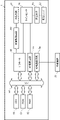
図1は、本実施形態における測定装置1の動作を説明するためのブロック図である。CPU50は、ROM51に格納されたプログラムを実行することで、I/Oポート54、光源駆動回路60、AD変換回路55、外部通信回路56、ROM51及びRAM52と協働して図1の制御部10として機能する。発光制御部11は、CPU50及び光源駆動回路60に対応し、白色光源21の発光強度を調整し、かつ、白色光源21の発光を制御する。白色光源21は、可視光全体にわたる発光波長分布を有する。白色光源21としては、例えば、タングステン光や白色LED、RGB(レッド、グリーン、ブルー)の3色LED等を使用可能である。本実施形態において白色光源21は、タングステン光を用いた白色LEDであるものとする。図3(A)は、本実施形態で用いる白色光源21の波長別の相対強度(輝度)を示している。
FIG. 1 is a block diagram for explaining the operation of the measuring
図1に示す様に、白色光源21が射出する光70は、ハウジング110の開口部500を、その法線方向に対して約45度の角度で通過して測定位置にある測定対象90である指先を照射する。そして、この照射光は、測定対象90の光吸収特性に応じた散乱光71となる。散乱光71の一部は、集光レンズ22により平行光72に変換され、回折格子23に90度の入射角で入射する。回折格子23は、入射光を波長に応じて分光する。分光された分散光73は、ラインセンサ24の各画素に入射する。ラインセンサ24の各画素は、入射した分散光73の受光量に応じた電圧を受光量検出部12に出力する。図3(B)は、ラインセンサ24の模式図である。本実施形態によるラインセンサ24は、波長約400nmから約1000nmの可視光を5nm単位で検出するために必要な120画素を有する。本実施形態では、ラインセンサ24の1番の画素が約400nm、120番の画素が約1000nmの波長を含む光を検出する様に、測定装置1は調整して組み立てられている。受光量検出部12は、CPU50、AD変換回路55及びI/Oポート54に対応する。実際には、AD変換回路55は、ラインセンサ24が出力する各画素の電圧をそれぞれ、例えば、12ビットのデジタル値に変換し、CPU50は、この各画素の受光量を示すデジタル値をAD変換回路55から取得する。本実施形態のラインセンサ24は、電荷蓄積型であり、所定の蓄積時間に入射した分散光の光量に応じて、画素ごとに電圧信号を出力する。ラインセンサ24での蓄積時間は、受光量検出部12、より詳しくは、CPU50がI/Oポート54を介してラインセンサ24に設定する。
As shown in FIG. 1, the light 70 emitted by the
第1生体信号生成部13は、所定画素の受光結果、つまり、受光量を示す値に基づき第1生体信号を生成する。本実施形態では、生体の指先を測定対象90とし、約590nmの波長を検知する38番の画素の受光量に基づき第1生体信号を生成する。この第1生体信号は、指尖容積脈波信号としても参照される。第1生体信号の生成に使用する約590nmの波長は、血液中のヘモグロビンでの吸光量が比較的大きい波長である。
The first
第2生体信号生成部19は、ラインセンサ24の複数の画素のうち、約660nmの波長を検知する52番の画素と、約940nmの波長を検知する108番の画素の受光量それぞれの時間変化を示す第2生体信号を生成して生体情報検知部20に出力する。生体情報検知部20は、第2生体信号に基づき経皮的動脈血酸素飽和度(SpO2)を判定する。SpO2は、動脈血中のヘモグロビンが酸素とどのくらい結合しているかをパーセントで示すものである。SpO2の検出において、生体情報検知部20は、SpO2の値Rを、R=P660/P940として求める。ここで、P660は、52番の画素(約660nm)の受光量であり、P940は108番の画素(約940nm)の受光量である。なお、SpO2は、同じタイミングでの52番の画素の受光量と、108番の画素の受光量により求める。生体情報検知部20は、事前に作成した値RとSpO2との校正曲線に、第2生体信号に基づき求めた値Rを当てはめることによりSpO2を判定する。
The second
外部通信部17は、外部通信回路56に対応し、外部機器30と通信を行う。外部機器30は、測定装置1に測定開始及び測定終了の指示を行う。また、測定装置1は、第1生体信号や、第1生体信号を複数回微分した信号や、第1生体信号の周期Cや、第1生体信号の特徴点や、判定したSpO2等を外部機器30に送信する。なお、外部機器30は、第1生体信号の周期Cから脈拍の値を算出することができる。さらに、外部機器30は、第1生体信号の特徴点及びその値に基づき血管の硬化度合いを判定することができる。外部機器30は、例えば、パーソナルコンピュータやタブレット端末である。なお、外部機器30との通信は、有線であっても無線であっても良い。条件変更部14については後述する。なお、制御部内でSpO2を判定するのではなく、第2生体信号を外部機器30に送信し、外部機器30がSpO2を判定する構成であっても良い。
The
図4は、生体情報の検出処理のフローチャートである。測定装置1は、外部機器30から測定開始指示を受信すると、S100で、測定条件A及びBを決定する。なお、測定条件は、例えば、白色光源21の発光強度や、ラインセンサ24の電荷蓄積時間(受光時間)である。また、測定条件Aは、第1生体信号を生成する際の測定条件であり、測定条件Bは、第2生体信号を生成する際の測定条件である。
FIG. 4 is a flowchart of biometric information detection processing. When the measurement start instruction is received from the
まず、測定条件Aの決定について説明する。例えば、発光制御部11は、白色光源21を所定の発光強度で発光させ、受光量検出部12は、第1生体信号の生成に使用する38番の画素の受光量を所定期間検出する。そして、制御部10は、所定期間で検出した受光量の最大値(ピーク値)がAD変換回路55により検出可能な電圧範囲の最大値付近となる様に、白色光源21の発光強度及び/又はラインセンサ24の電荷蓄積時間を決定し、これを測定条件Aとする。なお所定期間は、生成する第1生体信号である指尖容積脈波信号の1周期以上とし、例えば、2秒とすることができる。なお、S100で測定条件Aを決定するための白色光源21の発光強度については予め決めておく。そして、制御部10は、この発光強度と、38番の画素の受光量の最大値に基づき、測定条件Aを決定する。
First, determination of measurement conditions A will be described. For example, the light
続いて、測定条件Bの決定について説明する。上述した様に第2生体信号は、52番の画素(約660nm)の受光量と、108番の画素(約940nm)の受光量により生成される。したがって、測定条件Aの決定と同様に、発光制御部11は、白色光源21を所定の発光強度で発光させ、受光量検出部12は、52番と108番の画素の受光量を所定期間検出する。そして、制御部10は、所定期間で検出した52番と108番の画素の受光量がAD変換回路55により検出可能な電圧範囲の最大値付近となる様に、白色光源21の発光強度及び/又はラインセンサ24の電荷蓄積時間を決定し、これを測定条件Bとする。なお、測定条件AとBの決定は、並行して行うことも、個別に行うこともできる。なお、白色光源21の発光強度及び/又はラインセンサ24の電荷蓄積時間を所定期間毎に変化させながら、生体信号の生成に使用する画素の受光量の最大値が適切となる様に測定条件を決定する構成であっても良い。
Next, determination of measurement condition B will be described. As described above, the second biological signal is generated from the amount of light received by the 52nd pixel (approximately 660 nm) and the amount of received light by the 108th pixel (approximately 940 nm). Therefore, similarly to the determination of the measurement condition A, the light
制御部10は、決定した測定条件Aを発光制御部11及び受光量検出部12にS101で設定する。これにより、発光制御部11は、測定条件Aに従う発光強度で白色光源21を発光させる。また、受光量検出部12は、測定条件Aに従う電荷蓄積時間をラインセンサ24に設定する。第1生体信号生成部13は、38番の画素の各タイミングの受光量に基づき第1生体信号を生成し、周期算出部15及び特徴算出部16に第1生体信号を出力する。なお、第1生体信号生成部13は、38番の画素の各タイミングの受光量をそのまま時系列で示すことで第1生体信号を生成することができる。また、第1生体信号生成部13は、38番の画素の各タイミングの受光量を所定数毎に区切り、所定数の平均値を求め、この平均値を時系列で示すことで第1生体信号を生成することができる。また、第1生体信号生成部13は、38番の画素の所定数のタイミングの受光量の移動平均により生体信号を生成することができる。また、各タイミングの受光量又はその平均値を時系列で示す信号に対してフィルタ処理を行い、フィルタ処理後の信号を第1生体信号とすることができる。
The
周期算出部15は、S102で、第1生体信号の周期Cを第1生体信号の極値に基づき判定する。周期算出部15は、例えば、第1生体信号の局所的最小値の時間間隔に基づき第1生体信号の周期Cを判定する。図5(A)は、第1生体信号と、第1生体信号の周期C(C1~C4の4回分)の検出例を示している。また、周期算出部15は、第1生体信号を2回微分した加速度信号の局所的最大値の時間間隔に基づき第1生体信号の周期を判定することもできる。図5(B)は、加速度信号と、加速度信号の局所的最大値の時間間隔から判定される第1生体信号の周期C(C'1~C'4の4回分)の検出例を示している。
In S102, the
また、特徴算出部16は、S103で、第1生体信号の特徴点及びその値を算出する。本実施形態においては、第1生体信号の周期Cの開始タイミングを基点として、生体信号を2回微分した加速度信号の局所的最大値及び局所的最小値の最初の5つを特徴点とする。なお、第1生体信号の周期Cの開始タイミングは、第1生体信号の局所的最小値(極値)のタイミングとする。図5(C)は、5つの特徴点a、b、c、d及びeの一例をしている。なお、特徴算出部16は、第1生体信号を4回微分した信号の局所的最大値及び局所的最小値を特徴点とすることもできる。また、特徴点とする数は、4に限定されず、他の数であっても良い。より一般的には、特徴算出部16は、第1生体信号を1回以上微分した微分信号の変化点の情報を特徴量とすることができる。
In addition, the
特徴算出部16は、S103及びS104で、総ての特徴点を算出するまで特徴点の算出を継続する。条件変更部14は、特徴算出部16が総ての特徴点の算出を完了させると、S105で、第2生体信号の検出期間Qを判定する。図6は、検出期間Qの説明図である。図6のタイミングTaは、周期算出部15が、第1生体信号の周期C1の終わり、つまり、局所的最小値を検知したタイミングである。本実施形態において、周期算出部15は、生体信号の振幅が所定時間以上連続して上昇することを検出することにより、第1生体信号の局所的最小値を検出している。つまり、周期算出部15は、第1生体信号の周期C1の終了時間(局所的最小値となった時刻)を事後的に検出する。図6のタイミングTbは、特徴算出部16が総ての特徴点の算出を完了させたタイミングである。また、時刻CXは、現在の周期C2の終了時刻を予測した予測時刻である。条件変更部14は、周期C2の開始タイミングから1つ前の周期C1に対応する期間だけ後の時刻を予測時刻CXとして推定する。なお、1つ前の周期Cではなく、過去複数回の周期Cの平均値を用いて予測時刻CXを算出する構成とすることもできる。なお、第1生体信号の周期は変動するため、条件変更部14は、第1生体信号の変動量である変動マージンZを予測時刻CXの算出に使用することができる。この場合、条件変更部14は、周期C2の開始タイミングから1つ前の周期、或いは、過去複数回の周期の平均値だけ後の時刻より、変動マージンZだけ早い時刻を予測時刻CXとする。なお、変動マージンZの値は、予め、ROM51に格納されている。
In S103 and S104, the
条件変更部14は、予測時刻CXから変更時間Dだけ早いタイミングTcを求め、タイミングTcを検出期間の終了タイミングとする。そして、条件変更部14は、タイミングTbからタイミングTcまでの期間を検出期間Qとする。変更時間Dとは、測定条件Bから測定条件Aに変更してから、第1生体信号が安定し、よって、第1生体信号に基づく測定を行える様になるまでの時間である。例えば、白色光源21の発光強度を変更する場合には、発光強度の安定待ち時間が変更時間Dには含まれる。また、受光量検出部12がローパスフィルタ等のフィルタ回路を有する場合にはフィルタの時定数に基づく時間が変更時間Dに含まれる。さらに、第1生体信号生成部13が、時系列のデジタル値の移動平均処理等により生体信号を生成する場合には、平均処理に要する時間が変更時間Dには含まれる。なお、生体信号の局所的最小値の検出のため、局所的最小値となる前の生体信号の振幅の減少を所定期間だけ検出する必要がある場合、条件変更部14は、この所定期間を検知時間YとしてタイミングTcの算出に使用することができる。この場合、条件変更部14は、予測時刻CXから変更時間D及び検知時間Yの和だけ早いタイミングをタイミングTcとする。
The
図4に戻り、制御部10は、S106で、タイミングTbにおいて、決定した測定条件Bを発光制御部11及び受光量検出部12にS101で設定する。第2生体信号生成部19は、測定条件Bに切り替えた後、測定条件Aから測定条件Bへの変更時間が経過すると、第2生体信号を生成して生体情報検知部20に出力する。これにより、生体情報検知部20は、第2生体信号が示す52番の画素(約660nm)の受光量と、108番の画素(約940nm)の受光量とに基づきSpO2を判定する。なお、ラインセンサ24は、電荷蓄積時間毎に受光量を出力するため、生体情報検知部20は、検出期間Qの間、複数回、SpO2を判定する。また、生体情報検知部20は、検出期間Qが経過すると、当該検出期間の間に求めた複数のSpO2の平均値を求める。
Returning to FIG. 4, in S106, the
制御部10は、S106で、測定条件Bを設定した後、S107で検出期間Qが経過するまで待機する。制御部10は、検出期間Qが経過すると、S108(タイミングTc)において、測定条件Aを発光制御部11及び受光量検出部12に設定する。そして、制御部10は、S109で、外部機器30から測定終了指示を受信しているかを判定し、測定終了指示を受信するまで、S103からの処理を繰り返し行う。なお、外部通信部17は、第1生体信号の1周期が完了するたびに、加速度信号と、生体信号の周期Cと、特徴点及びその値と、SpO2の平均値とを外部機器30に出力する。
After setting the measurement condition B in S106, the
以上、第1生体信号を生成して生体情報を測定する間は、第1生体信号の生成に適した測定条件を設定する。そして、第1生体信号の過去1つ以上の周期に基づき、第1生体信号の現周期が終了すると予測される予測時刻CXを求める。そして、現周期の第1生体信号から特徴点を算出すると、そのタイミングと予測時刻CXとに基づき第2生体信号に基づく生体情報の検知期間Qを判定する。なおこのとき、測定条件の変更に要する時間を考慮する。そして、検知期間Qにおいては、第2生体信号の生成に適した測定条件を設定する。この構成により、第1生体信号からの特徴点の算出を継続しながら、第2生体信号からのSpO2の判定を精度良く行うことができる。つまり、測定を中断することなく、検出対象の複数の生体情報に適した測定条件を使用することができ、各生体情報の検出精度を向上させることができる。なお、本実施形態では、検知期間Qには、測定条件Aから測定条件Bへの切り替えに必要な変更時間が含まれていた。しかしながら、測定条件Aから測定条件Bへの変更時間を検知期間Qから除外する構成とすることもできる。この場合、検知期間Qの開始タイミングは、タイミングTbより、測定条件Aから測定条件Bへの変更時間だけ後のタイミングとなる。 As described above, while the first biological signal is generated and the biological information is measured, measurement conditions suitable for generating the first biological signal are set. Then, based on one or more past cycles of the first biosignal, a predicted time CX at which the current cycle of the first biosignal is expected to end is obtained. Then, when the feature point is calculated from the first biosignal of the current period, the detection period Q of the biometric information based on the second biosignal is determined based on the timing and the predicted time CX. At this time, consider the time required to change the measurement conditions. Then, in the detection period Q, measurement conditions suitable for generating the second biosignal are set. With this configuration, it is possible to accurately determine SpO2 from the second biosignal while continuing to calculate feature points from the first biosignal. That is, it is possible to use measurement conditions suitable for a plurality of pieces of biological information to be detected without interrupting the measurement, and to improve detection accuracy of each piece of biological information. Note that in the present embodiment, the detection period Q includes a change time required for switching from the measurement condition A to the measurement condition B. FIG. However, it is also possible to adopt a configuration in which the change time from the measurement condition A to the measurement condition B is excluded from the detection period Q. FIG. In this case, the start timing of the detection period Q is the timing after the change time from the measurement condition A to the measurement condition B from the timing Tb.
<第二実施形態>
続いて、第二実施形態について、第一実施形態との相違点を中心に説明する。本実施形態において、生体情報検知部20は、SpO2に加えてカルボキシヘモグロビン濃度(SpCO)も判定する。SpCOは、約620nmの波長を検知する44番の画素と、約660nmの波長を検知する52番の画素と、約810nmの波長を検知する82番の画素と、約940nmの波長を検知する108番の画素の受光量に基づき検出することができる。なお、これら4つの波長の受光量に基づきSpCOを判定する方法は、例えば、特許文献4に記載されている。
<Second embodiment>
Next, the second embodiment will be described, focusing on differences from the first embodiment. In the present embodiment, the
図7は、本実施形態による生体情報の検出処理のフローチャートである。なお、図4のフローチャートと同様のステップについては、同じステップ番号を付与してその説明を省略する。測定装置1は、外部機器30から測定開始指示を受信すると、S200で、測定条件A、B及びCを決定する。測定条件A及びBは、第一実施形態と同様である。測定条件Cは、SpCOを測定するための条件であり、SpCOを検出するための4つの波長を受光する画素の受光量の最大値がAD変換回路55により検出可能な電圧範囲の最大値付近とするための条件である。
FIG. 7 is a flowchart of biometric information detection processing according to the present embodiment. Note that steps similar to those in the flow chart of FIG. 4 are assigned the same step numbers, and descriptions thereof are omitted. When the measurement start instruction is received from the
S105で、検出期間Qを判定すると、条件変更部14は、測定回数が奇数回目であるか否かをS201で判定する。測定回数が奇数回目であると、条件変更部14は、測定条件Bを発光制御部11及び受光量検出部12にS106で設定する。また、第2生体信号生成部19は、52番の画素(約660nm)と108番の画素(約940nm)の受光量を示す第2生体信号を生成する。これにより、生体情報検知部20は、検出期間Qの間、SpO2を判定する。一方、測定回数が偶数回目であると、条件変更部14は、測定条件Cを発光制御部11及び受光量検出部12にS202で設定する。また、第2生体信号生成部19は、44番の画素(約620nm)と、53番の画素(約660nm)と、82番の画素(約810nm)と、108番の画素(約940nm)の受光量を示す第2生体信号を生成する。これにより、生体情報検知部20は、検出期間Qの間、SpCOを判定する。なお、本実施形態においては、外部通信部17は、第1生成信号の1周期毎に、SpO2とSpCOを交互に外部機器30に出力する。
After determining the detection period Q in S105, the
以上、本実施形態では、第1生体信号の1周期毎に第2生体信号を生成するための画素を切り替える。この構成により、検出する生体情報の種類を、検出精度を落とすことなく多くすることができる。なお、第2生体信号で検出する生体情報は3以上とすることもできる。この場合も、各生体情報の測定条件を求め、第1生体信号の1周期毎に順次、1つの測定条件を選択して設定する。なお、複数種類の生体情報の測定順序を示す情報は、予めROM51に格納しておく。
As described above, in the present embodiment, the pixels for generating the second biosignal are switched for each cycle of the first biosignal. With this configuration, it is possible to increase the types of biometric information to be detected without lowering the detection accuracy. It should be noted that three or more biometric information can be detected from the second biosignal. Also in this case, the measurement conditions for each biometric information are obtained, and one measurement condition is selected and set sequentially for each cycle of the first biosignal. Information indicating the order of measurement of multiple types of biological information is stored in the
なお、測定条件として、白色光源21の発光強度及びラインセンサ24の電荷蓄積時間を例にして上記実施形態を説明した。なお、測定条件は、これらに限定されず、例えば、ラインセンサ24の受光感度(ゲイン)を測定条件として使用する構成とすることもできる。また、第二実施形態では、1つの検知期間Q内では、SpO2又はSpCOの検知のみを行っていた。しかしながら、検知期間Qの時間に応じて、1つの検知期間Qを前半と後半に分け、前半ではSpO2を検知し、後半ではSpCOを検知する構成とすることもできる。
The above embodiment has been described with the emission intensity of the
なお、上記実施形態において、測定装置1のラインセンサ24は、測定対象90からの反射光を受光するものであったが、透過光を受光する構成とすることもできる。また、本発明の測定装置1の外観や、機械的構造は、図8に示すものに限定されない。
In the above-described embodiment, the
[その他の実施形態]
本発明は、上述の実施形態の1以上の機能を実現するプログラムを、ネットワーク又は記憶媒体を介してシステム又は装置に供給し、そのシステム又は装置のコンピュータにおける1つ以上のプロセッサーがプログラムを読出し実行する処理でも実現可能である。また、1以上の機能を実現する回路(例えば、ASIC)によっても実現可能である。
[Other embodiments]
The present invention supplies a program that implements one or more functions of the above-described embodiments to a system or device via a network or a storage medium, and one or more processors in the computer of the system or device reads and executes the program. It can also be realized by processing to It can also be implemented by a circuit (for example, ASIC) that implements one or more functions.
21:白色光源、23:回折格子、24:ラインセンサ、13:第1生体信号生成部、15:周期判定部、16:特徴量算出部、19:生体情報検知部、14:条件変更部、10:制御部 21: White light source, 23: Diffraction grating, 24: Line sensor, 13: First biological signal generator, 15: Period determination unit, 16: Feature amount calculation unit, 19: Biological information detection unit, 14: Condition change unit, 10: control unit
Claims (15)
前記受光手段の第1画素の受光結果から脈波に関する信号である生体信号を生成する生成手段と、
前記生体信号の周期を判定する判定手段と、
前記生体信号の各周期において、前記生体信号を微分した値である前記生体信号の特徴量を検出する第1検出手段と、
前記受光手段の複数の第2画素の受光結果から酸素飽和度に関する情報、又はカルボキシヘモグロビン濃度に関する情報である生体情報を検出する第2検出手段と、
前記生体信号を生成するための第1測定条件と、前記第2検出手段による前記生体情報の検出のための第2測定条件を決定する決定手段と、
前記生体信号の各周期において、前記第2検出手段による検出の終了タイミングを判定し、前記第1検出手段が前記特徴量を検出するまでは前記第1測定条件を前記分光センサに設定し、前記第1検出手段が前記特徴量を検出してから前記終了タイミングまでは前記第2測定条件を前記分光センサに設定する設定手段と、
を備えていることを特徴とする測定装置。 a light source that emits light toward a measurement position; spectroscopic means that disperses light reflected from the living body at the measurement position or transmitted light that has passed through the living body at the measurement position according to wavelength; and a plurality of pixels. wherein each pixel of the plurality of pixels includes a light receiving means for receiving light containing a predetermined wavelength separated by the spectroscopic means;
generating means for generating a biological signal, which is a pulse wave-related signal, from the light receiving result of the first pixel of the light receiving means;
determination means for determining the cycle of the biosignal;
a first detection means for detecting a feature amount of the biosignal, which is a value obtained by differentiating the biosignal, in each cycle of the biosignal;
a second detection means for detecting biological information, which is information about oxygen saturation or information about carboxyhemoglobin concentration, from the light receiving results of the plurality of second pixels of the light receiving means;
a determination means for determining a first measurement condition for generating the biomedical signal and a second measurement condition for detection of the biometric information by the second detection means;
In each cycle of the biological signal, the end timing of the detection by the second detection means is determined, and the first measurement condition is set to the spectroscopic sensor until the first detection means detects the feature quantity, setting means for setting the second measurement condition to the spectroscopic sensor from when the first detection means detects the characteristic quantity until the end timing;
A measuring device comprising:
前記設定手段は、推定した前記終了時刻より、前記第2測定条件から前記第1測定条件への変更に要する時間と前記判定手段が前記生体信号の極値を検出するために必要な所定の時間との和だけ早いタイミングを前記終了タイミングとすることを特徴とする請求項2又は3に記載の測定装置。 The determination means determines a period of the biosignal based on the extreme value of the biosignal,
Based on the estimated end time, the setting means determines the time required for changing from the second measurement condition to the first measurement condition and the predetermined time required for the determination means to detect the extreme value of the biological signal. 4. The measuring apparatus according to claim 2 or 3, wherein a timing earlier by the sum of and is set as the end timing.
前記第2検出手段は、前記第2測定条件に変更されると、前記第1測定条件から前記第2測定条件への変更に要する時間が経過してから前記終了タイミングまでの間、前記複数の第2画素の受光結果に基づき前記生体情報を検出することを特徴とする請求項1から5のいずれか1項に記載の測定装置。 The setting means changes to the second measurement condition when the first detection means detects the feature quantity,
When the measurement condition is changed to the second measurement condition, the second detection means detects the plurality of 6. The measuring device according to any one of claims 1 to 5, wherein the biometric information is detected based on the light receiving result of the second pixel.
前記決定手段は、複数種類の前記生体情報それぞれの検出のための複数の前記第2測定条件を決定することを特徴とする請求項6に記載の測定装置。 The second detection means detects a plurality of types of the biological information from light reception results of the plurality of second pixels,
7. The measuring apparatus according to claim 6, wherein said determining means determines a plurality of said second measurement conditions for detecting each of said plurality of types of said biological information.
前記設定手段は、前記生体信号の各周期において、複数種類の前記生体情報のうちの1つの前記生体情報を前記測定順序に従い選択し、前記第1検出手段が前記特徴量を検出すると、選択した前記生体情報を検出するための前記第2測定条件に変更することを特徴とする請求項7又は8に記載の測定装置。 further comprising holding means for holding information indicating the order of measurement of the plurality of types of biological information;
The setting means selects one of the plurality of types of the biological information according to the measurement order in each cycle of the biological signal, and when the first detection means detects the feature amount, the selected 9. The measuring device according to claim 7, wherein the measuring condition is changed to the second measuring condition for detecting the biological information.
1つ以上のプロセッサーと、
を有する測定装置の前記1つ以上のプロセッサーで実行されると、
前記測定装置に、
第1測定条件を前記分光センサに設定することと、
前記第1測定条件が設定された状態で、前記受光手段の第1画素の受光結果から脈波に関する信号である生体信号を生成することと、
前記生体信号の周期を判定することと、
前記生体信号の各周期において、前記生体信号を微分した値である前記生体信号の特徴量を検出することと、
前記生体信号の各周期において、酸素飽和度に関する情報、又はカルボキシヘモグロビン濃度に関する情報である生体情報の検出の終了タイミングを判定することと、
前記生体信号の各周期において前記生体信号の特徴量を検出すると、第2測定条件を前記分光センサに設定することと、
前記第2測定条件が前記分光センサに設定されると、前記終了タイミングまで、前記受光手段の複数の第2画素の受光結果から前記生体情報を検出することと、
を実行させることを特徴とするプログラム。 a light source that emits light toward a measurement position; spectroscopic means that disperses light reflected from the living body at the measurement position or transmitted light that has passed through the living body at the measurement position according to wavelength; and a plurality of pixels. wherein each pixel of the plurality of pixels includes a light receiving means for receiving light containing a predetermined wavelength separated by the spectroscopic means;
one or more processors;
when executed on the one or more processors of a measurement device having
to the measuring device,
setting a first measurement condition to the spectroscopic sensor;
Generating a biological signal, which is a pulse wave-related signal, from the light receiving result of the first pixel of the light receiving means in a state where the first measurement condition is set;
determining a period of the biosignal;
detecting a feature amount of the biosignal, which is a value obtained by differentiating the biosignal, in each cycle of the biosignal;
Determining end timing of detection of biometric information, which is information on oxygen saturation or information on carboxyhemoglobin concentration, in each cycle of the biosignal;
setting a second measurement condition to the spectroscopic sensor when detecting a feature amount of the biosignal in each cycle of the biosignal;
When the second measurement condition is set in the spectroscopic sensor, the biometric information is detected from light reception results of the plurality of second pixels of the light receiving means until the end timing;
A program characterized by causing the execution of
Priority Applications (3)
| Application Number | Priority Date | Filing Date | Title |
|---|---|---|---|
| JP2018060735A JP7129189B2 (en) | 2018-03-27 | 2018-03-27 | Biological measuring device and program |
| CN201910231521.0A CN110301888A (en) | 2018-03-27 | 2019-03-26 | Measuring device and computer readable storage medium |
| US16/364,261 US20190298192A1 (en) | 2018-03-27 | 2019-03-26 | Living body measurement apparatus and computer-readable storage medium |
Applications Claiming Priority (1)
| Application Number | Priority Date | Filing Date | Title |
|---|---|---|---|
| JP2018060735A JP7129189B2 (en) | 2018-03-27 | 2018-03-27 | Biological measuring device and program |
Publications (3)
| Publication Number | Publication Date |
|---|---|
| JP2019170542A JP2019170542A (en) | 2019-10-10 |
| JP2019170542A5 JP2019170542A5 (en) | 2021-04-30 |
| JP7129189B2 true JP7129189B2 (en) | 2022-09-01 |
Family
ID=68168400
Family Applications (1)
| Application Number | Title | Priority Date | Filing Date |
|---|---|---|---|
| JP2018060735A Active JP7129189B2 (en) | 2018-03-27 | 2018-03-27 | Biological measuring device and program |
Country Status (1)
| Country | Link |
|---|---|
| JP (1) | JP7129189B2 (en) |
Families Citing this family (2)
| Publication number | Priority date | Publication date | Assignee | Title |
|---|---|---|---|---|
| JP7432454B2 (en) * | 2020-06-30 | 2024-02-16 | 日本特殊陶業株式会社 | Oxygen saturation measuring device |
| JP6989192B1 (en) * | 2020-12-24 | 2022-01-05 | メディカルフォトニクス株式会社 | Arteriosclerosis measuring device, arteriosclerosis measuring program, and how to operate the arteriosclerosis measuring device |
Citations (5)
| Publication number | Priority date | Publication date | Assignee | Title |
|---|---|---|---|---|
| JP2005278758A (en) | 2004-03-29 | 2005-10-13 | Nippon Koden Corp | Concentration measuring instrument of light absorbing substance in blood |
| US20100280342A1 (en) | 2009-04-30 | 2010-11-04 | The General Electric Company | Multiple wavelength physiological measuring apparatus, sensor and interface unit for determination of blood parameters |
| JP2011115459A (en) | 2009-12-04 | 2011-06-16 | Nippon Soken Inc | Device and method for detecting biological information |
| JP2012115640A (en) | 2010-11-09 | 2012-06-21 | Nippon Koden Corp | Biological signal measuring apparatus and biological signal measuring method |
| JP2017055840A (en) | 2015-09-14 | 2017-03-23 | 株式会社島津製作所 | Optical measurement device |
Family Cites Families (1)
| Publication number | Priority date | Publication date | Assignee | Title |
|---|---|---|---|---|
| JP3345481B2 (en) * | 1993-09-22 | 2002-11-18 | 興和株式会社 | Pulse wave spectrometer |
-
2018
- 2018-03-27 JP JP2018060735A patent/JP7129189B2/en active Active
Patent Citations (5)
| Publication number | Priority date | Publication date | Assignee | Title |
|---|---|---|---|---|
| JP2005278758A (en) | 2004-03-29 | 2005-10-13 | Nippon Koden Corp | Concentration measuring instrument of light absorbing substance in blood |
| US20100280342A1 (en) | 2009-04-30 | 2010-11-04 | The General Electric Company | Multiple wavelength physiological measuring apparatus, sensor and interface unit for determination of blood parameters |
| JP2011115459A (en) | 2009-12-04 | 2011-06-16 | Nippon Soken Inc | Device and method for detecting biological information |
| JP2012115640A (en) | 2010-11-09 | 2012-06-21 | Nippon Koden Corp | Biological signal measuring apparatus and biological signal measuring method |
| JP2017055840A (en) | 2015-09-14 | 2017-03-23 | 株式会社島津製作所 | Optical measurement device |
Also Published As
| Publication number | Publication date |
|---|---|
| JP2019170542A (en) | 2019-10-10 |
Similar Documents
| Publication | Publication Date | Title |
|---|---|---|
| US20210113121A1 (en) | Non-invasive medical monitoring device for blood analyte measurements | |
| JP4639321B2 (en) | Biological information measuring device | |
| KR102487058B1 (en) | Apparatus and method for measuring bio-information | |
| US20140081153A1 (en) | Pulse data detecting apparatus, pulse data detecting method, and storage medium having pulse data detection program recorded thereon | |
| KR20190081051A (en) | Apparatus for measuring biological signal and operating method thereof | |
| US20050049469A1 (en) | Pulse oximeter | |
| CN104968259A (en) | System and method for determining vital sign information of a subject | |
| JP7299726B2 (en) | Skin color measuring device and program | |
| US20140350365A1 (en) | Measurement device, measurement method, program and recording medium | |
| JP7129189B2 (en) | Biological measuring device and program | |
| US20180333088A1 (en) | Pulse Oximetry Capturing Technique | |
| JP2018007894A (en) | Measuring device, measuring method, and measuring program | |
| JP4385677B2 (en) | Biological information measuring device | |
| JP2016002167A (en) | Wrist fitting type pulse oximeter | |
| JP4553954B2 (en) | Blood component concentration measuring apparatus and blood component concentration measuring method | |
| JP5407768B2 (en) | Pulse measuring device | |
| JP2019170540A (en) | Biometric measurement device and program | |
| JP6103373B2 (en) | Pulse wave measuring device | |
| US10660552B2 (en) | Detection device and detection method | |
| CN111479498A (en) | Method and system for automatic brightness/gain control in measuring local oral inflammation | |
| JP7090460B2 (en) | Biometric information measuring devices and programs | |
| WO2022050368A1 (en) | Pulse wave signal acquisition device | |
| US20190298192A1 (en) | Living body measurement apparatus and computer-readable storage medium | |
| JP7281930B2 (en) | Biological information measuring device and program | |
| JP6530892B2 (en) | Biological information display device |
Legal Events
| Date | Code | Title | Description |
|---|---|---|---|
| RD01 | Notification of change of attorney |
Free format text: JAPANESE INTERMEDIATE CODE: A7421 Effective date: 20210103 |
|
| A521 | Request for written amendment filed |
Free format text: JAPANESE INTERMEDIATE CODE: A523 Effective date: 20210113 |
|
| A521 | Request for written amendment filed |
Free format text: JAPANESE INTERMEDIATE CODE: A523 Effective date: 20210318 |
|
| A621 | Written request for application examination |
Free format text: JAPANESE INTERMEDIATE CODE: A621 Effective date: 20210318 |
|
| A977 | Report on retrieval |
Free format text: JAPANESE INTERMEDIATE CODE: A971007 Effective date: 20220218 |
|
| A131 | Notification of reasons for refusal |
Free format text: JAPANESE INTERMEDIATE CODE: A131 Effective date: 20220225 |
|
| A521 | Request for written amendment filed |
Free format text: JAPANESE INTERMEDIATE CODE: A523 Effective date: 20220422 |
|
| A131 | Notification of reasons for refusal |
Free format text: JAPANESE INTERMEDIATE CODE: A131 Effective date: 20220520 |
|
| A521 | Request for written amendment filed |
Free format text: JAPANESE INTERMEDIATE CODE: A523 Effective date: 20220713 |
|
| TRDD | Decision of grant or rejection written | ||
| A01 | Written decision to grant a patent or to grant a registration (utility model) |
Free format text: JAPANESE INTERMEDIATE CODE: A01 Effective date: 20220719 |
|
| A61 | First payment of annual fees (during grant procedure) |
Free format text: JAPANESE INTERMEDIATE CODE: A61 Effective date: 20220822 |
|
| R151 | Written notification of patent or utility model registration |
Ref document number: 7129189 Country of ref document: JP Free format text: JAPANESE INTERMEDIATE CODE: R151 |