JP7129175B2 - Upper body disposable swimwear - Google Patents
Upper body disposable swimwear Download PDFInfo
- Publication number
- JP7129175B2 JP7129175B2 JP2018033170A JP2018033170A JP7129175B2 JP 7129175 B2 JP7129175 B2 JP 7129175B2 JP 2018033170 A JP2018033170 A JP 2018033170A JP 2018033170 A JP2018033170 A JP 2018033170A JP 7129175 B2 JP7129175 B2 JP 7129175B2
- Authority
- JP
- Japan
- Prior art keywords
- side seal
- width direction
- upper body
- rear direction
- waist
- Prior art date
- Legal status (The legal status is an assumption and is not a legal conclusion. Google has not performed a legal analysis and makes no representation as to the accuracy of the status listed.)
- Active
Links
Images


Description
本発明は、装着中のずれ上がり防止性に優れる上半身用使い捨て水着に関するものである。 TECHNICAL FIELD The present invention relates to a disposable swimsuit for the upper body that is excellent in preventing slippage during wear.
現在では、乳幼児のプール等での使用を前提とした使い捨て水着(スイミングパンツとも呼ばれている)が市販されている。この使い捨て水着は下半身用のものであり、尿や便等の排泄物が水中に拡散するのを防止するためのものである(例えば特許文献1、2参照)。
Currently, disposable swimsuits (also called swimming pants) intended for use in infant pools and the like are commercially available. This disposable swimsuit is for the lower body and is intended to prevent excreta such as urine and feces from diffusing into the water (see
これに対し、女の子用として、女の子らしさを強調するため胸を隠す上半身用使い捨て水着も提案されている(特許文献3)。 On the other hand, for girls, an upper-body disposable swimsuit that hides the breasts has been proposed to emphasize femininity (Patent Document 3).
しかしながら、従来の上半身用使い捨て水着は、装着中の身体の動き、特に水遊びや遊泳中に多い腕の上げ下げにより、ずれ上がることがあった。 However, conventional upper-body disposable swimsuits tend to slip up due to body movements during wearing, especially when the arms are frequently raised and lowered during water play and swimming.
そこで、本発明の主たる課題は、使用時のずれ上がりを抑制する上半身用使い捨て水着を提供することにある。 SUMMARY OF THE INVENTION Accordingly, it is a primary object of the present invention to provide a disposable swimsuit for the upper body that suppresses slipping up during use.
上記課題を解決した上半身用使い捨て水着は以下のとおりである。 A disposable swimsuit for the upper body that solves the above problems is as follows.
<第1の態様>
上半身前部を覆う前身頃と、上半身後部を覆う後身頃とを備え、
下部に形成された胴開口、上部に形成された首開口、首開口の幅方向両側に位置する一対の肩部、一対の肩部の側方に開口する一対の腕開口、及び腕開口の下端を通る幅方向仮想線と胴開口との間に位置する胴周り部を有し、
胴周り部の両側部に、前身頃の両側部と後身頃の両側部との接合部が配されたサイドシール部を有し、
前身頃及び後身頃の少なくとも一方におけるサイドシール部の幅方向の内側には、幅方向に弾性伸縮する伸縮領域が設けられている、
上半身用使い捨て水着であって、
胴周り部における前後方向の少なくとも一部の範囲は、伸縮領域を有するとともに、左右のサイドシール部の幅方向の間隔が胴開口側に向かうにつれて段階的又は連続的に狭くなった間隔減少部分である、
ことを特徴とする、上半身用使い捨て水着。
<First Aspect>
Equipped with a front body covering the front part of the upper body and a back body covering the rear part of the upper body,
A torso opening formed in the lower part, a neck opening formed in the upper part, a pair of shoulders positioned on both sides in the width direction of the neck opening, a pair of arm openings opening to the sides of the pair of shoulders, and lower ends of the arm openings Having a waist portion located between the width direction imaginary line passing through and the waist opening,
On both sides of the torso part, there are side seal parts where the joints between both sides of the front body and both sides of the back body are arranged,
An elastic region that elastically expands and contracts in the width direction is provided on the inner side of the side seal portion in at least one of the front body and the back body in the width direction.
A disposable swimsuit for the upper body,
At least part of the range in the front-rear direction of the waist portion has an elastic region, and is a space reduction portion in which the width direction space between the left and right side seal portions narrows stepwise or continuously toward the side of the waist opening. be,
A disposable swimsuit for the upper body, characterized by:
(作用効果)
本上半身用使い捨て水着では、胴周り寸法は左右のサイドシール部の幅方向の間隔により決まる。つまり、本上半身用使い捨て水着の間隔減少部分は、伸縮領域を有するとともに、胴周り寸法が胴開口側に向かうにつれて段階的又は連続的にきつくなる部分である。このような間隔減少部分を有していると、本上半身用使い捨て水着を装着中に、本上半身用使い捨て水着がずれ上がるような力が働いたとしても、より強く肌に密着する間隔減少部分が抵抗となり、ずれ上がりが抑制される。
(Effect)
In this upper-body disposable swimsuit, the waist size is determined by the widthwise interval between the left and right side seal portions. In other words, the space reduction portion of the present upper-body disposable swimsuit has an elastic region and a portion where the waist circumference dimension becomes tighter in a stepwise or continuous manner toward the waist opening side. With such a reduced interval portion, even if a force is applied to the disposable upper body disposable swimsuit while wearing it, the reduced interval portion is in tighter contact with the skin. It acts as a resistance, and slippage is suppressed.
<第2の態様>
間隔減少部分よりも上側に、左右のサイドシール部の幅方向の間隔が胴開口側に向かうにつれて広がる間隔増加部分を有している、
第1の態様の上半身用使い捨て水着。
<Second Aspect>
Above the space decreasing portion, there is a space increasing portion where the space between the left and right side seal portions in the width direction widens toward the body opening side.
A disposable swimsuit for upper body according to the first aspect.
(作用効果)
この場合、胴周り部の寸法の前後方向の変化が幼児体形に近いものとなり、ずれ上り抑制効果がさらに向上するため好ましい。
(Effect)
In this case, the change in the size of the waist portion in the front-rear direction is close to that of a child's body, which is preferable because the effect of suppressing slipping up is further improved.
<第3の態様>
間隔減少部分における間隔変化率が8~31%である、
第1又は2の態様の上半身用使い捨て水着。
<Third Aspect>
The interval change rate in the interval decreasing portion is 8 to 31%,
A disposable swimsuit for the upper body according to the first or second aspect.
(作用効果)
間隔減少部分における間隔変化の程度は適宜定めることができるが、通常の場合、本範囲内とすることが好ましい。
なお、間隔変化率とは、幅方向の間隔の最大値をDmax、幅方向の間隔の最小値をDmin、サイドシール部の前後方向の長さをZとしたとき、以下の式(1)により定まるものである。
{(Dmax - Dmin) / Z} × 100 ・・・(1)
(Effect)
Although the extent of the interval change in the interval decreasing portion can be determined as appropriate, it is preferably within this range in normal cases.
Note that the gap change rate is defined by the following formula (1), where Dmax is the maximum value of the gap in the width direction, Dmin is the minimum value of the gap in the width direction, and Z is the length of the side seal portion in the front-rear direction. It is determined.
{(Dmax−Dmin)/Z}×100 (1)
<第4の態様>
左右のサイドシール部は、最も幅方向の外側に位置し、胴周り部の前後方向の全体にわたり設けられた主サイドシール部と、主サイドシール部より幅方向の内側に位置し、間隔減少部分にのみ設けられた補助サイドシール部とを、それぞれ含み、
補助サイドシール部を有する部分における、左右のサイドシール部の幅方向の間隔が、補助サイドシール部を有しない部分における、左右のサイドシール部の幅方向の間隔よりも狭くなっている、
第1~3のいずれか1つの態様の上半身用使い捨て水着。
<Fourth Aspect>
The left and right side seal portions are composed of a main side seal portion positioned on the outermost side in the width direction and extending over the entire length of the waist in the front-rear direction, and a portion positioned on the inner side in the width direction of the main side seal portion to reduce the gap. Auxiliary side seal portions provided only in the
The widthwise interval between the left and right side seal portions in the portion having the auxiliary side seal portion is narrower than the widthwise interval between the left and right side seal portions in the portion not having the auxiliary side seal portion.
A disposable swimsuit for the upper body according to any one of the first to third aspects.
(作用効果)
間隔減少部分を形成するために、一本の連続する接合部又は一列に配列された接合部からなるサイドシール部を斜めに設けることもできる。しかし、その場合、間隔減少部分では、サイドシール部の外側に前身頃及び後身頃の余剰部分が別々に大きく残り、見栄えが悪くなる。この余剰部分は切断することもできるが、廃材が発生してしまう。これに対して、本態様のように、主サイドシール部と補助サイドシール部とを設けると、サイドシール部の外側に前身頃及び後身頃の余剰部分が残るものの、それらは主サイドシール部により接合されているため、非接合の場合と比べれば見栄えは悪化しない。さらに、この余剰部分は、本上半身用使い捨て水着を下に図り下ろす際の摘みとして用いることも可能である(前身頃及び後身頃の余剰部分が別々に残る場合に、いずれか一方だけ引っ張ると、主サイドシール部がはがれるおそれがある)。
(Effect)
Side seals can also be provided obliquely to form the reduced spacing, which can consist of a single continuous joint or a row of joints. In this case, however, large surplus portions of the front body and the back body remain separately outside the side seal portions at the portion where the interval is reduced, resulting in an unattractive appearance. Although this surplus portion can be cut off, waste material is generated. On the other hand, when the main side seal portions and the auxiliary side seal portions are provided as in this aspect, although the surplus portions of the front body and the back body remain outside the side seal portions, they are covered by the main side seal portions. Since it is bonded, the appearance does not deteriorate as compared with the non-bonded case. Furthermore, this surplus part can also be used as a knob when pulling down this upper body disposable swimsuit (if the surplus parts of the front body and the back body are left separately, if only one of them is pulled, (The main side seal may come off.)
<第5の態様>
補助サイドシール部は、一列又は幅方向に間隔を空けて複数列設けられており、
各補助サイドシール部の接合部は剥離可能である、
第4の態様の上半身用使い捨て水着。
<Fifth Aspect>
The auxiliary side seal portions are provided in one row or in multiple rows at intervals in the width direction,
The junction of each auxiliary side seal is detachable,
A disposable swimsuit for the upper body of the fourth aspect.
(作用効果)
このように補助サイドシール部の接合部が剥離可能であると、例えば補助サイドシール部が一列の場合には、使用者が補助サイドシール部を剥離するか又はしないかを選択することにより、ずれ上り抑制機能の有無を選択することができる。また、補助サイドシール部が複数列ある場合には、使用者が装着者の身体のサイズに応じて、一部の補助サイドシール部の列のみを剥離することにより、間隔減少部分における胴周り寸法のきつさを調節することができる。
(Effect)
If the joining portion of the auxiliary side seal portion can be peeled off in this way, for example, when the auxiliary side seal portions are arranged in a row, the user can select whether or not to peel off the auxiliary side seal portion. It is possible to select whether or not there is an uplink suppression function. In addition, when there are multiple rows of auxiliary side seals, the user can peel off only some rows of the auxiliary side seals according to the size of the wearer's body, thereby reducing the waist circumference at the reduced interval. You can adjust the tightness of the
<第6の態様>
肩部に、前後方向に沿うギャザー弾性部材が設けられており、
肩部の少なくとも一部は、ギャザー弾性部材の収縮により前後方向に収縮しているとともに、ギャザー弾性部材とともに前後方向に伸長可能である、
第1~5のいずれか1つの態様の上半身用使い捨て水着。
<Sixth Aspect>
A gathered elastic member is provided on the shoulder portion along the front-rear direction,
At least part of the shoulder shrinks in the front-rear direction due to contraction of the gathers elastic member, and can extend in the front-rear direction together with the gathers elastic member.
A disposable swimsuit for the upper body according to any one of the first to fifth aspects.
(作用効果)
本上半身用使い捨て水着では、肩部の少なくとも一部は、ギャザー弾性部材の収縮により前後方向に収縮しているとともに、ギャザー弾性部材とともに前後方向に伸長可能であるため、非常に簡素な構造でありながら肩部のフィット性が良好となる。
(Effect)
In this upper-body disposable swimsuit, at least a part of the shoulder shrinks in the front-rear direction due to the contraction of the gathering elastic member, and can be stretched in the front-rear direction together with the gathering elastic member, so that the structure is very simple. However, the fit of the shoulder is improved.
本発明によれば、使用時のずれ上がりを抑制できる、等の利点がもたらされる。 ADVANTAGE OF THE INVENTION According to this invention, the advantage of being able to suppress the shifting up at the time of use etc. is brought about.
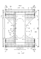
以下、上半身用使い捨て水着について、添付図面を参照しつつ詳説する。図1~図7は、上半身用使い捨て水着を示している。この上半身用使い捨て水着は、上半身前部を覆う前身頃Fと、上半身後部を覆う後身頃Bとを備えるとともに、下部に形成された胴開口WO、上部に形成された首開口NO、首開口の幅方向WD両側に位置する一対の肩部S、及び一対の肩部Sの側方に開口する一対の腕開口AO、及び腕開口AOの下端を通る幅方向WD仮想線と胴開口WOとの間に位置する胴周り部Tを備えたものである。 The upper body disposable swimsuit will be described in detail below with reference to the accompanying drawings. Figures 1-7 show a disposable upper body swimsuit. This upper-body disposable swimsuit includes a front body F covering the front part of the upper body, a back body B covering the rear part of the upper body, and a body opening WO formed in the lower part, a neck opening NO formed in the upper part, and a neck opening. A pair of shoulders S positioned on both sides in the width direction WD, a pair of arm openings AO opening to the sides of the pair of shoulders S, and a virtual line in the width direction WD passing through the lower ends of the arm openings AO and the waist opening WO. It has a torso portion T located therebetween.
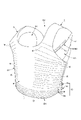
図1のほか、図6及び図7等にも示すように、肩部Sには、前後方向LDに沿うギャザー弾性部材63が設けられているのは、一つの好ましい形態である。そして、肩部Sの少なくとも一部は、ギャザー弾性部材63の収縮により前後方向LDに収縮しているとともに、ギャザー弾性部材63とともに前後方向LDに伸長可能となっている。この結果、本上半身用使い捨て水着では、非常に簡素な構造でありながら肩部Sのフィット性が良好となる。
As shown in FIG. 6 and FIG. 7 in addition to FIG. 1, it is one preferred form that the shoulder portion S is provided with a gathered
各部の構造は特に限定されるものではない。図示例は、パンツタイプ使い捨ておむつの製造技術を利用できる点で好ましいものである。すなわち、図示例の上半身用使い捨て水着は、製品外面(裏面)をなす外装体100と、外装体100に取り付けられた内装体200とを備えている。符号Yは展開状態における製品の全長(前身頃Fの胴開口WOの縁から後身頃Bの胴開口WOの縁までの前後方向長さ)を示しており、符号Xは展開状態における製品の全幅を示している。
The structure of each part is not particularly limited. The illustrated example is preferable in that the technology for manufacturing pants-type disposable diapers can be used. That is, the illustrated upper-body disposable swimsuit includes an
各構成部材は必要に応じて表裏少なくとも一方側に隣接する部材に接合される。この部材間の接合は、いずれか一方又は両方の部材に対して塗布されたホットメルト接着剤により行うことができる。断面図における点模様部分はその表側及び裏側に位置する各構成部材を接合する接合手段としてのホットメルト接着剤を示している。ホットメルト接着剤は、スロット塗布、連続線状又は点線状のビード塗布、スパイラル状、Z状等のスプレー塗布、又はパターンコート(凸版方式でのホットメルト接着剤の転写)等、公知の手法により塗布することができる。これに代えて又はこれとともに、弾性部材の固定部分では、ホットメルト接着剤を弾性部材の外周面に塗布し、弾性部材を隣接部材に固定することができる。ホットメルト接着剤としては、例えばEVA系、粘着ゴム系(エラストマー系)、オレフィン系、ポリエステル・ポリアミド系などの種類のものが存在するが、特に限定無く使用できる。各構成部材を接合する接合手段としてはヒートシールや超音波シール等の素材溶着による手段を用いることもできる。 Each component is joined to an adjacent member on at least one of the front and back sides as required. The joining between the members can be performed by a hot-melt adhesive applied to either one or both members. A dot pattern portion in the cross-sectional view indicates a hot-melt adhesive as a bonding means for bonding each component located on the front side and the back side. The hot melt adhesive is applied by known methods such as slot coating, continuous line or dotted line bead coating, spiral or Z-shaped spray coating, or pattern coating (transfer of hot melt adhesive by letterpress method). can be applied. Alternatively or additionally, at the fixing portion of the elastic member, a hot melt adhesive can be applied to the outer peripheral surface of the elastic member to fix the elastic member to the adjacent member. Hot-melt adhesives include, for example, EVA-based, adhesive rubber-based (elastomer-based), olefin-based, and polyester-polyamide-based adhesives, and can be used without particular limitation. As a joining means for joining each constituent member, a means by material welding such as heat sealing or ultrasonic sealing can be used.
(外装体)
外装体100は、前身頃Fから首開口NOの幅方向WD両側に位置する一対の肩部Sを経て後身頃Bに至るものであり、これら前身頃Fにおける外装体100の両側部と後身頃Bにおける外装体100の両側部とがそれぞれ接合されたサイドシール部13を有している。また、このサイドシール部13の形成により、図6及び図7に示すように、下部には胴開口WOが、上部の幅方向WD中央には首開口NOが形成され、及び一対の肩部Sの側方に開口する一対の腕開口AOが形成される。
(Exterior body)
The
外装体100は、胴開口WOから腕開口AOの下端までの前後方向範囲として定まる胴周り部Tと、腕開口AOを形成する部分の前後方向範囲(前身頃Fのサイドシール部13を有する前後方向領域と後身頃Bのサイドシール部13を有する前後方向領域との間)として定まる中間部Mとを有する。胴周り部Tは、概念的に胴開口の縁部を形成する「胴下端部」Wと、これよりも上側の部分である「胸部」Uとに分けることができる。通常、胴周り部T内に幅方向WDの伸縮応力が変化する境界(例えば弾性部材の太さや伸長率が変化する)を有する場合は、最も胴開口WO側の境界よりも胴開口WO側が胴下端部Wとなり、このような境界が無い場合は内装体200よりも胴開口WO側に延び出た部分が胴下端部Wとなる。これらの前後方向LDの寸法は、製品のサイズによって異なり、適宜定めることができるが、一例を挙げると、胴下端部Wは15~40mm、胸部Uは65~120mmとすることができる。
The
外装体100における中間部Mの両側縁は装着者の腕周りに沿うようにコ字状又は曲線状に括れている。外装体100の括れの程度は適宜定めることができ、すっきりとした外観とするためには、外装体100の幅は最も幅が狭い部分で内装体200の幅より狭くすることが好ましいが、最も幅が狭い部分でも内装体200の幅以上となるようにしてもよい。
Both side edges of the intermediate portion M of the
図示しないが、外装体100を、前身頃F及び後身頃Bに別々に設け、これらを必要に応じて前後方向LDに離間させ、内装体200を介して前側の外装体100及び後側の外装体100を連結することもできる。
Although not shown, the
外装体100は、単層のシート層で形成することもできる。しかし、フィット性を向上させるためには、後述するように外装体100に弾性部材15~19を内蔵させることが好ましい。また、単層では剛性確保が困難であったり、内面の素材と外面の素材を異なるものとしたりすることも考えられる。よって、外装体100は図1~図5に示されるように、外側シート層12S及び内側シート層12Hが貼り合わされた積層構造を有するものが好ましい。外側シート層12S及び内側シート層12Hを形成するシート材は、共通の一枚のシート材とする他、個別のシート材とすることもできる。すなわち、前者の場合、外装体100の一部又は全部において、胴開口WOの縁等で折り返された一枚のシート材の内側の部分及び外側の部分により内側シート層12H及び外側シート層12Sがそれぞれ形成される。なお、前者の形態では、シート材の資材数が少ないという利点があり、後者の形態では内側シート層12H及び外側シート層12Sを貼り合わせる際に位置ずれしにくいという利点がある。図示例は後者に相当するものであり、内側シート層12Hを形成するシート材は胴開口WOの縁までしか延在していないが、外側シート層12Sを形成するシート材は、内側シート層12Hのシート材のウエスト側の縁を回り込んでその内側に折り返されている。また、この折り返し部分は、内装体200の胴開口WO側の端部と重なる位置まで、外装体100の幅方向WD全体にわたり延在するカバーシート層12rとなっている。カバーシート層12rは、外側シート層12Sのシート材を折り返して形成せずに、専用のシート材を、内側シート層12Hの内側に貼り付けてもよい。
The
外側シート層12S及び内側シート層12Hに用いるシート材としては、シート状のものであれば特に限定無く使用できるが、少なくとも一方、好ましくは両方に不織布が使用される。ここで、外側シート層12S及び内側シート層12Hを含め、本上半身用使い捨て水着に用いることが可能な不織布は以下のとおりである。すなわち、不織布の構成繊維としては、例えばポリエチレン、ポリプロピレン又はそのコポリマー(例えばポリエチレンや、エチレンを共重合成分として配合したコポリマー)等のオレフィン系、ポリエステル系、ポリアミド系等の合成繊維(単成分繊維の他、芯鞘等の複合繊維も含む)の他、レーヨンやキュプラ等の再生繊維、綿等の天然繊維等、特に限定なく選択することができ、これらを混合して用いることもできる。不織布の柔軟性を高めるために、構成繊維を捲縮繊維とするのは好ましい。また、不織布の構成繊維は、親水性繊維(親水化剤により親水性となったものを含む)であっても、疎水性繊維若しくは撥水性繊維(撥水剤により撥水性となった撥水性繊維を含む)であってもよい。また、不織布は一般に繊維の長さや、シート形成方法、繊維結合方法、積層構造により、短繊維不織布、長繊維不織布、スパンボンド不織布、メルトブローン不織布、スパンレース不織布、サーマルボンド(エアスルー)不織布、ニードルパンチ不織布、ポイントボンド不織布、積層不織布(スパンボンド層間にメルトブローン層を挟んだSMS不織布、SMMS不織布等)等に分類されるが、これらのどの不織布も用いることができる。
The sheet material used for the
外側シート層12S及び内側シート層12Hに不織布を用いる場合、その構成繊維の繊度、目付け及び厚みは適宜定めることができるが、通常の場合、それぞれ1.8~6.0dtex程度、10~30g/m2程度、0.1~1.3mm程度であると好ましい。
When non-woven fabric is used for the
胴周りに対するフィット性を高めるために、前身頃F及び後身頃Bの少なくとも一方におけるサイドシール部13の幅方向WDの内側には、幅方向WDに弾性伸縮する伸縮領域が設けられる。図示例の外装体100では、両シート層12S,12H間に細長状等の弾性部材15~19が設けられており、この弾性部材15~19を有する部位(図示例では胴周り部T及び中間部Mの一部)が幅方向WDに弾性伸縮する伸縮領域となっている。弾性部材15~19としては、図示例では細長状(糸状、紐状、帯状等)のものを用いているが、網状やシート状のものを用いることもできる。また、弾性部材15~19は合成ゴムを用いても、天然ゴムを用いても良い。外装体100の両シート層12S,12Hの貼り合わせや、その間に挟まれる弾性部材15~19の固定には種々の塗布方法によるホットメルト接着剤を用いることができるほか、素材溶着(ヒートシールや超音波接着)を用いることもできる。
In order to improve the fit around the waist, at least one of the front body F and the back body B is provided with a stretchable region elastically stretchable in the width direction WD inside the
図示例についてより詳細に説明すると、後身頃B及び前身頃Fの胴下端部Wにおける内側シート層12Hの内側面と外側シート層12Sの折り返しにより形成されたカバーシート層12rの外側面との間には、幅方向全体にわたり連続するように、複数の胴下端部弾性部材17が前後方向LDに間隔を空けて、かつ所定の伸長率で幅方向WDに沿って伸長された状態で設けられている。また、胴下端部弾性部材17のうち、胸部Uに隣接する領域に配設される1本または複数本については、内装体200と重なっていてもよいし、内装体200と重なる幅方向中央部を除いてその幅方向両側にそれぞれ設けてもよい。この胴下端部弾性部材17としては、太さ155~1880dtex、特に310~1240dtex程度(合成ゴムの場合。天然ゴムの場合には断面積0.05~1.5mm2、特に0.1~1.0mm2程度)の糸ゴムを、4~12mmの間隔で3~22本程度、それぞれ伸長率150~400%、特に220~320%程度で固定するのが好ましい。また、胴下端部弾性部材17は、そのすべてが同じ太さと伸長率にする必要はなく、例えば胴下端部Wの上部と下部で弾性部材の太さと伸長率が異なるようにしてもよい。
To explain the illustrated example in more detail, between the inner surface of the
また、前身頃F及び後身頃Bの胸部Uにおける内側シート層12Hの外側面と外側シート層12Sの内側面との間には、内装体200と重なる幅方向中央部を除いて、その上側及び幅方向両側の各部位に、幅方向全体にわたり連続するように、胸部弾性部材15,19が複数本、前後方向LDに間隔を空けて、かつ所定の伸長率で幅方向WDに沿って伸長された状態で固定されている。
In addition, except for the central portion in the width direction that overlaps the
胸部弾性部材15,19としては、太さ155~1880dtex、特に310~1240dtex程度(合成ゴムの場合。天然ゴムの場合には断面積0.05~1.5mm2、特に0.1~1.0mm2程度)の糸ゴムを、1~15mm、特に3~8mmの間隔で5~30本程度、それぞれ伸長率200~350%、特に240~300%程度で固定するのが好ましい。
The chest
また、前身頃F及び後身頃Bの中間部Mにおける内側シート層12Hの外側面と外側シート層12Sの内側面との間には、内装体200と重なる幅方向中央部を除いて、その幅方向両側の各部位に、幅方向全体にわたり連続するように、中間部弾性部材16,18が複数本、前後方向LDに間隔を空けて、かつ所定の伸長率で幅方向WDに沿って伸長された状態で固定されている。
In addition, except for the central portion in the width direction overlapping with the
中間部弾性部材16,18としては、太さ155~1880dtex、特に310~1240dtex程度(合成ゴムの場合。天然ゴムの場合には断面積0.05~1.5mm2、特に0.1~1.0mm2程度)の糸ゴムを、5~40mm、特に5~20mmの間隔で2~10本程度、それぞれ伸長率150~300%、特に180~260%で固定するのが好ましい。
The intermediate
なお、図示のように、胸部弾性部材15,19及び中間部弾性部材16,18が、内装体200と幅方向WDに重なる部分の一部又は全部を含む幅方向中間(好ましくは内装体200と外装体100との接合領域の全体を含む)を除いてその幅方向両側にそれぞれ設けられていると、内装体200が幅方向WDに必要以上に収縮することがなく、モコモコと見た目が悪かったりすることがない。この形態には、幅方向両側にのみ弾性部材が存在する形態の他、内装体200を横切ってその幅方向一方側から他方側まで弾性部材が存在しているが、内装体200と重なる幅方向中央部では弾性部材が一か所又は多数個所で細かく切断され、収縮力が作用せず(実質的には、弾性部材を設けないことに等しい)に、その幅方向両側のみが収縮力作用部分として構成されている形態も含まれる。もちろん胸部弾性部材15,19及び中間部弾性部材16,18の配設形態は上記例に限るものではなく、胸部Uの幅方向全体にわたり伸縮力が作用するように、胸部弾性部材15,19及び中間部弾性部材16,18の一部又は全部を、内装体200を横切ってその幅方向一方側から他方側まで設けることもできる。
As shown in the figure, the chest
(サイドシール部)
サイドシール部13は、図9(b)(c)に拡大して示すように、前身頃Fの側部と後身頃Bの側部との接合部14が配された部分である。この接合部14の接合は、ヒートシールや超音波シールのような素材溶着により行うことができるほか、ホットメルト接着剤により行うこともできる。サイドシール部13は、連続する単一の接合部14であってもよいが、接合部14が間隔を空けて多数配列された部分であると好ましい。左右のサイドシール部13における接合部14のパターンは同じであることが一般的であるが、異なっていてもよい。
(Side seal part)
The
多数の接合部14の配列によりサイドシール部13を形成する場合、各接合部14の形状は適宜定めることができ、三角形等の多角形、特に正多角形や、半円形、星形、円形、楕円形等特に限定されない。また、接合部14はすべて同一形状かつ同一寸法であってもよいし、形状及び寸法の少なくとも一方が異なる複数種の接合部14が組み合わされていてもよい。各接合部14の寸法は適宜定めることができる。通常の場合、各接合部14の前後方向寸法14yは0.6~2.5mm程度とすることができる。各接合部14の幅方向寸法14xは0.6~7.0mm程度とすることができる。また、各接合部14の前後方向の間隔14dは0.5~5.0mm程度とすることができる。
When the
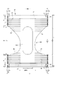
特徴的には、図1、図2、図6~図9に示すように、胴周り部Tにおける前後方向の少なくとも一部の範囲は、伸縮領域を有するとともに、左右のサイドシール部13の幅方向WDの間隔D1,D2が胴開口WO側に向かうにつれて段階的(図示例のように1段階とするほか、複数段階でも、又は連続的でもよい)に狭くなった間隔減少部分101となっている。本上半身用使い捨て水着では、胴周り寸法は左右のサイドシール部13の幅方向WDの間隔D1,D2により決まる。よって、この間隔減少部分101を有していると、図8に概略的に示す装着状態からも分かるように、本上半身用使い捨て水着を装着中に、本上半身用使い捨て水着がずれ上がるような力が働いたとしても、より強く肌に密着する間隔減少部分101が抵抗となり、ずれ上がりが抑制される。なお、図9(a)に図示された間隔D1,D2からも分かるように、左右のサイドシール部13の幅方向WDの間隔は、幅方向WDに複数の接合部14が配列されているときには最も内側(中央側)の接合部14における間隔を意味する。
Characteristically, as shown in FIGS. 1, 2, and 6 to 9, at least a partial range in the front-rear direction of the waist portion T has an elastic region, and the width of the left and right
間隔減少部分101の位置は適宜定めることができる。通常の場合、間隔減少部分101は、胴周り部Tにおける胴開口WO側に位置していることが好ましい。具体例としては、図9(a)に示すように、サイドシール部13と胴開口WOとの交点の位置を0%とし、サイドシール部13と腕開口AOとの交点の位置を100%としたとき、15~40%の位置よりも下側(胴開口WO側)全体が間隔減少部分101となっていることが好ましい。間隔減少部分101よりも上側(腕開口AO側)は、左右のサイドシール部13の幅方向WDの間隔D1が一定の部分とすることができる。
The position of the
また、間隔減少部分101よりも上側(腕開口AO側)の部分102は、左右のサイドシール部13の幅方向WDの間隔D3が、胴開口WO側に向かうにつれて広がる間隔増加部分103を有することもできる。この例は、胴周り部Tの寸法の前後方向の変化が幼児体形に近いものであり、ずれ上り抑制効果をさらに向上させることができる点で好ましいものである。
In addition, a
間隔減少部分101における間隔変化の程度は適宜定めることができるが、通常の場合、以下に定義される間隔変化率αが8~31%であると好ましい。すなわち、ここにいう間隔変化率αとは、幅方向間隔の最大値(図9(a)の例ではD1)をDmax、幅方向WDの間隔の最小値(図9(a)の例ではD2)をDmin、サイドシール部13の前後方向の長さをZとしたとき、以下の式(1)により定まるものである。
α = {(Dmax - Dmin) / Z} × 100 ・・・(1)
Although the extent of the gap change in the
α = {(Dmax−Dmin)/Z}×100 (1)
サイドシール部13は間隔減少部分101を形成しうる限り、特に限定されない。例えば、図8(a)に示すように、サイドシール部13は前後方向LDに沿う直線状の部分が階段状に配置された形状とすることができる。また、図示しないが、サイドシール部13を構成する接合部14が斜め方向に沿って直線状に並ぶ形状としたり、図8(b)に示すようにサイドシール部13を構成する接合部14が身体表面に沿う曲線状に並ぶ形状としたりすることもできる。
The
このように、間隔減少部分101を形成するために、一列に配列された接合部14からなるサイドシール部13を斜めに設けることもできる。しかし、その場合、間隔減少部分101では、サイドシール部13の外側に前身頃F及び後身頃Bの余剰部分が別々に大きく残り、見栄えが悪くなる。この余剰部分は切断することもできるが、廃材が発生してしまう。したがって、図示例のように、左右のサイドシール部13として、最も幅方向WDの外側に位置し、胴周り部Tの前後方向LDの全体にわたり設けられた主サイドシール部13aと、主サイドシール部13aより幅方向WDの内側に位置し、間隔減少部分101にのみ設けられた補助サイドシール部13bとをそれぞれ設けるのは好ましい。この場合、補助サイドシール部13bを有する部分は、左右のサイドシール部13の幅方向WDの間隔が、補助サイドシール部13bを有しない部分よりも狭い間隔減少部分101となる。これにより、サイドシール部13の外側に前身頃F及び後身頃Bの余剰部分105が残るものの、それらは主サイドシール部13aにより接合されているため、非接合の場合と比べれば見栄えは悪化しない。さらに、この余剰部分105は、本上半身用使い捨て水着を下に図り下ろす際の摘みとして用いることも可能である(前身頃F及び後身頃Bの余剰部分が別々に残る場合に、いずれか一方だけ引っ張ると、主サイドシール部13aがはがれるおそれがある)。
In this way, in order to form the
補助サイドシール部13bは、図9(b)等に示すように左右それぞれに一列設けるほか、図9(c)に示すように幅方向WDに間隔を空けて複数列設けることもできる。
The auxiliary
補助サイドシール部13bの接合部14は剥離可能であると好ましい。例えば補助サイドシール部13bが一列の場合には、使用者が補助サイドシール部13bを剥離するか又はしないかを選択することにより、ずれ上り抑制機能の有無を選択することができる。また、図9(c)に示すように補助サイドシール部13bが複数列ある場合には、使用者が装着者の身体のサイズに応じて、一部の補助サイドシール部13bの列(一列又は複数列)のみを剥離することにより、間隔減少部分101における胴周り寸法のきつさを調節することができる。
It is preferable that the
(内装体)
内装体200は肩部Sより前側から肩部Sを経て肩部Sより後側に延びる部分であり、任意の形状を採ることができるが、図示例では長方形の前後方向LDの中間かつ幅方向WDの中間に首開口NOが形成されたものとなっている。内装体200は、単層のシート層で形成することもできる。しかし、単層では剛性確保が困難であり、後述する起き上がりギャザー60の取付けや、外装体100に対する取付けが困難となることが考えられる。よって、内装体200は図3~図5に示されるように、身体側となるトップシート30と、外装体100側となるバックシート11とを含む積層構造を有していることが好ましい。トップシート30及びバックシート11としては各種の不織布を好適に用いることができる。また、図3~図5に示す例のように、トップシート30及びバックシート11の少なくとも一方の両側部を折り返し、側部の剛性を向上させてもよい。さらに、図11及び図12に示す例のように、トップシート30とバックシート11との間に、別の補強シート40を内蔵し、内装体200全体としての剛性を向上させることもできる。この補強シート40は、図示例のように、2つ折りにする等、複数回折り畳んだ状態で内蔵させることができる。この補強シート40としては、例えばJISL1913に規定されるカンチレバー法による剛軟度が0.4~10mN・cmの不織布(例えば繊度1.8~6.0dtex、目付け5~40g/m2程度のエアスルー不織布(サーマルボンド不織布)、スパンボンド不織布、SMMS不織布のようにスパンボンド不織布層間にメルトブローン不織布層を挟んだ積層不織布等)を用いることができる。
(inner body)
The
内装体200の寸法は特に限定されるものではない。通常の場合、内装体200の幅方向寸法200Xは製品全幅Xの30~50%程度とすることができ、内装体200の前後方向寸法200Yは製品全長Yの50~100%程度とすることができる。内装体200の前後方向LDの位置は特に限定されず、製品の前後方向LDの中央に配置するほか、製品の前側又は後側に偏らせて配置してもよい。
The dimensions of the
(起き上がりギャザー)
内装体200の両側部には、図示例のように肌側に起き上がる起き上がりギャザー60を設け、この起き上がりギャザー60にギャザー弾性部材63を設けるのは一つの好ましい形態である。すなわち、この起き上がりギャザー60は、内装体200の前後方向LD長さに等しい長さを有する帯状のギャザーシート62を幅方向WDに折り返して二つに折り重ねるとともに、折り返し部分及びその近傍のシート間に、細長状のギャザー弾性部材63を長手方向に沿って伸長状態で、幅方向WDに間隔をあけて複数本固定してなるものである。起き上がりギャザー60のうち先端部と反対側に位置する基端部(幅方向WDにおいてシート折り返し部分と反対側の端部)は内装体200の側縁部の裏面に固定された付根部分65とされている。付根部分65以外の部分は、付根部分65から内装体200の側方で内装体200の表側に折り返された本体部分66(折り返し部分側の部分)とされている。本体部分66のうち、内装体200の表側に位置する部分は、幅方向中央側に向かう付け根側部分と、この付け根側部分の先端から幅方向外側に折り返された先端側部分とを有している。本体部分66の前側の一部は倒伏状態でトップシート30の側部表面に対してホットメルト接着剤やヒートシールにより固定されて形成された倒伏部分67となり、本体部分66の後側の一部は倒伏状態でトップシート30の側部表面に対してホットメルト接着剤やヒートシールにより固定されて形成された倒伏部分67となっている。そして、本体部分66における前後の倒伏部分67の間に位置する部分は、非固定の起き上がり部分68となっており、この起き上がり部分68の少なくとも先端部には前後方向LDに沿うギャザー弾性部材63が伸長状態で固定されている。
(Getting up gathers)
It is one preferred form to provide rise gathers 60 that rise on the skin side on both sides of the
ギャザー弾性部材63は、このように起き上がりギャザー60とともに設けると、装着者の肩から浮き上がりにくく、特に良好なフィット性を得ることができる。
When the gathering
ギャザー弾性部材63によるギャザー伸縮領域E1の前後方向LDの寸法と位置は適宜定めればよく、例えば図10に示す例のように、上半身用使い捨て水着の前後方向LDの中央よりも前側から後側まで、特に内装体200の前端部から後端部までギャザー弾性部材63によるギャザー伸縮領域E1を有していると、フィット性は良好となる。ただし、この場合、装着時に正面側から見たとき、肩部S部分に収縮皺が見える。また、肌に最も負荷が加わる部分である肩部Sの頂部に収縮皺が形成されるため、肌触りが悪化するおそれがあるとともに、肌に収縮皺の跡がつくおそれもある。よって、図1等に示す例のように、自然長状態で、上半身用使い捨て水着の前後方向LDの中央よりも後側に、ギャザー弾性部材63によるギャザー伸縮領域E1を有するとともに、上半身用使い捨て水着の前後方向LDの中央及びこれよりも前側にはギャザー弾性部材63によるギャザー伸縮領域E1を有しないのも好ましい。このように、ギャザー弾性部材63を後身頃B側に偏らせて配置することにより、装着状態では、後身頃B側のギャザー伸縮領域E1が収縮することにより、前身頃F側のギャザー非伸縮領域E2が肩部Sの頂点に位置することとなる。この結果、装着時に正面側から見たとき、肩部Sに収縮皺が見えないため外観が良好になる。また、肌に最も負荷が加わる部分である肩部Sの頂部に収縮皺が形成されないため、肌触りが良好となるとともに、肌に収縮皺の跡がつきにくくなる。
The size and position in the front-rear direction LD of the gathered stretchable region E1 by the gathered
ギャザー弾性部材63によるギャザー伸縮領域E1は、自然長の状態でギャザー弾性部材63の収縮により前後方向LDに収縮しているとともに、前後方向LDに引張ることによりギャザー弾性部材63とともに前後方向LDに伸長可能な領域である。したがって、ギャザー弾性部材63は有するものの伸縮性が殺されている領域はギャザー伸縮領域E1ではなく、ギャザー非伸縮領域E2となる。ギャザー弾性部材63によるギャザー伸縮領域E1の前端は、自然長状態で、上半身用使い捨て水着の前後方向LDの中央よりも後側に位置している限り、展開状態で、上半身用使い捨て水着の前後方向LDの中央と同じか、又はより前側に位置していてもよい。通常の場合、ギャザー弾性部材63によるギャザー伸縮領域E1の前端は、展開状態で、上半身用使い捨て水着の前後方向LDの中央に位置しているか、又はより後側(例えば全長の10%程度の範囲)に位置させることができる。
The gather stretchable region E1 by the gather
前後の倒伏部分67の前後方向LDの寸法と位置、及び起き上がり部分68の前後方向LDの寸法と位置は適宜定めることができるが、通常の場合と同様に、ギャザー弾性部材63によるギャザー伸縮領域E1は倒伏部分67に設けずに、起き上がり部分68にのみ設けることが望ましい。よって、図1等に示す例のように、自然長の状態で、上半身用使い捨て水着の前後方向LDの中央よりも後側にギャザー伸縮領域E1を有し、上半身用使い捨て水着の前後方向LDの中央及びこれよりも前側はギャザー非伸縮領域E2となっている場合には、ギャザー伸縮領域E1の全体は起き上がり部分68となっており、かつギャザー非伸縮領域E2の前後方向LDのほぼ全体が前側の倒伏部分67となっていることが望ましい。また、後側の倒伏部分67は本体部分66の後端部のみに設けることが望ましい。
The dimensions and positions of the front and rear fallen
ギャザーシート62としてはスパンボンド不織布(SS、SSS等)やSMS不織布(SMS、SSMMS等)、メルトブロー不織布等の柔軟で均一性・隠蔽性に優れた不織布に、必要に応じてシリコーンなどにより撥水処理を施したものを好適に用いることができ、この場合における不織布の目付けは10~30g/m2程度とすることができる。ギャザー弾性部材63としては、太さ470~1240dtex程度、より好ましくは620~940dtex程度の糸ゴム等の細長状の弾性部材を用いることができる。ギャザー弾性部材63の伸長率は、150~350%が好ましく、200~300%がより好ましい。
As the gather
起き上がり部分68に設けられるギャザー弾性部材63の本数は2~6本が好ましく、3~5本がより好ましい。ギャザー弾性部材63の配置間隔60dは3~10mmが適当である。ギャザー弾性部材63は、起き上がり部分68の先端側だけでなく付け根側にも配置することができる。
The number of gathered
起き上がりギャザー60の付根部分65の取り付け対象は、特に限定されず、例えば内装体200におけるトップシート30及びバックシート11の少なくとも一方に対して、ホットメルト接着剤やヒートシールにより取り付けることができる。
The attachment target of the
起き上がりギャザー60の寸法は適宜定めることができる。通常の場合、例えば図3に示すように、起き上がりギャザー60の起立高さ(展開状態における本体部分66の幅方向長さ)W6は15~60mm、特に20~40mmであるのが好ましい。また、起き上がりギャザー60をトップシート30表面と平行になるように、平坦に折り畳んだ状態において最も内側に位置する折り目間の離間距離W3は60~190mm、特に70~140mmであるのが好ましい。
The dimensions of the rising gathers 60 can be determined as appropriate. Normally, as shown in FIG. 3, the standing height (the widthwise length of the
図13及び図14に示す例のように、内装体200におけるシート間に、前後方向LDに沿うギャザー弾性部材63を内蔵させることもできる。この場合、起き上がりギャザー60は省略することができる。また、図示例における内装体200を省略し、外装体100に前後方向LDに沿うギャザー弾性部材63を取り付けるだけとしてもよい。
As in the example shown in FIGS. 13 and 14, a gather
(首開口)
首開口NOは、外装体100に内装体200を取り付けた後に、ホールカッターで打ち抜くことにより形成することができる。また、外装体100及び内装体200に個別に首開口NOを構成する開口を形成し、両者の開口が重なるように外装体100に内装体200を取り付けてもよい。後者の場合、外装体100の開口及び内装体200の開口は寸法、形状が異なるものとすることができ、その場合、両者の開口の重なる部分が上半身用使い捨て水着の首開口NOとなる。
(neck opening)
The neck opening NO can be formed by punching out with a hole cutter after attaching the
首開口NOの形状は特に限定されるものではなく、長辺が前後方向LDに沿う長方形、長辺が前後方向LDに沿う角丸長方形、長軸が前後方向LDに沿う楕円形、対角線の長い方が前後方向LDに沿うひし形等、適宜の形状とすることができる。また、首開口NOの形状は前後対称とするほか、前後非対称とすることもできる。なお、首開口NOの両側縁が、ギャザー弾性部材63によるギャザー伸縮領域E1と前後方向LDにおいて重なる範囲で、伸縮方向(つまり前後方向LD)に沿っていないと、肩部Sがギャザー弾性部材63の収縮に伴いある程度収縮した状態では、肩部Sに形成される収縮皺が不規則になりやすい。そこで、図10(a)に示す例のように、首開口NOの両側縁は、ギャザー弾性部材63によるギャザー伸縮領域E1と前後方向LDにおいて重なる範囲では、前後方向LDに沿う直線状をなしている形態も提案される。これにより、肩部Sに形成される収縮皺がより規則的となり、より好ましい外観となる。この場合、首開口NOの両側縁は、ギャザー弾性部材63によるギャザー伸縮領域E1と前後方向LDにおいて重らない範囲では、前後方向LDに直線状となっていなくてもよい。
The shape of the neck opening NO is not particularly limited. It can have an appropriate shape such as a rhombus along the front-rear direction LD. Further, the shape of the neck opening NO may be symmetrical in the front-rear direction, or may be asymmetrical in the front-rear direction. If both side edges of the neck opening NO overlap with the elastic gather region E1 of the elastic gather
首開口NOと起き上がりギャザー60との位置関係は特に限定されないが、図示例のように、展開状態で、首開口NOの両側縁は、起き上がりギャザー60の先端よりも幅方向WD中央側に位置していると、製造時に首開口NOを切断しやすいため好ましい。 The positional relationship between the neck opening NO and the rising gathers 60 is not particularly limited, but as in the illustrated example, both side edges of the neck opening NO are positioned closer to the center in the width direction WD than the tips of the rising gathers 60 in the unfolded state. This is preferable because the neck opening NO can be easily cut during manufacturing.
さらに、図示例のように、首開口NOの前端は、前側の倒伏部分67の後端と同じかそれよりも前側に位置しており、首開口NOの後端は、後側の倒伏部分67の前端と同じかそれよりも後側に位置していると、肩部S以外の部分(特に、図示例では弾性部材15~19により幅方向に収縮する部分)が前後方向LDに収縮しないため、見栄えが良好となる。しかし、首開口NOの前端が、前側の倒伏部分67の後端より後側に位置していてもよく、首開口NOの後端が後側の倒伏部分67の前端よりも前側に位置していてもよく、あるいはその両方であってもよい。
Furthermore, as in the illustrated example, the front end of the neck opening NO is located at the same position as or forward than the rear end of the front lying
具体的な首開口NOの寸法は適宜定めればよいが。通常の場合、首開口NOの幅方向寸法Xnは製品全幅Xの0~40%程度とすることができ、首開口NOの前後方向寸法Ynは製品全長Yの30~75%程度とすることができる。なお、首開口NOの幅方向寸法Xnが製品全幅Xの0%の場合とは、首開口NOがスリットのように展開状態で幅を有しない場合を意味している。首開口NOの幅方向寸法Xnが製品全幅Xの0%よりも大きければ、首開口NOが展開状態でも幅を有することになるが、予め十分に開いた首開口NOを有する形態とするには、首開口NOの幅方向寸法Xnは製品全幅Xの10%より大きいことが好ましく、20%より大きいとより好ましい。首開口NOの前後方向LDの位置は特に限定されず、製品の前後方向LDの中央に配置するほか、製品の前側又は後側に偏らせて配置してもよい。 The specific dimensions of the neck opening NO may be determined as appropriate. Normally, the width dimension Xn of the neck opening NO can be about 0 to 40% of the total product width X, and the front-rear dimension Yn of the neck opening NO can be about 30 to 75% of the total product length Y. can. The case where the width dimension Xn of the neck opening NO is 0% of the total width X of the product means the case where the neck opening NO has no width in the unfolded state like a slit. If the width dimension Xn of the neck opening NO is larger than 0% of the total width X of the product, the neck opening NO will have a width even in the unfolded state. , the width dimension Xn of the neck opening NO is preferably larger than 10% of the overall product width X, more preferably larger than 20%. The position of the neck opening NO in the front-rear direction LD is not particularly limited, and it may be arranged at the center of the product in the front-rear direction LD, or it may be arranged at the front or rear side of the product.
<明細書中の用語の説明>
明細書中の以下の用語は、明細書中に特に記載が無い限り、以下の意味を有するものである。
<Description of terms in the specification>
The following terms in the specification have the following meanings unless otherwise specified in the specification.
・「前後方向」とは図中に符号LDで示す方向(縦方向)を意味し、「幅方向」とは図中にWDで示す方向(左右方向)を意味し、前後方向と幅方向とは直交するものである。 ・"Front-back direction" means the direction (longitudinal direction) indicated by symbol LD in the figure, and "width direction" means the direction (left-right direction) indicated by WD in the figure. are orthogonal.
・「表側」とは上半身用使い捨て水着を着用した際に着用者の肌に近い方を意味し、「裏側」とは上半身用使い捨て水着を着用した際に着用者の肌から遠い方を意味する。 ・"Front side" means the side closer to the wearer's skin when wearing a disposable upper body swimsuit, and "back side" means the side farther from the wearer's skin when wearing a disposable upper body swimsuit. .
・「表面」とは部材の、上半身用使い捨て水着を着用した際に着用者の肌に近い方の面を意味し、「裏面」とは上半身用使い捨て水着を着用した際に着用者の肌から遠い方の面を意味する。 ・"Front surface" means the side of the member that is closest to the wearer's skin when wearing the upper body disposable swimsuit, and the "back side" means that the upper body disposable swimsuit means the far side.
・「伸長率」は、自然長を100%としたときの値を意味する。例えば、伸長率が200%とは、伸長倍率が2倍であることと同義である。 - "Elongation rate" means a value when the natural length is taken as 100%. For example, an elongation rate of 200% is synonymous with an elongation ratio of 2 times.
・「目付け」は次のようにして測定されるものである。試料又は試験片を予備乾燥した後、標準状態(試験場所は、温度23±1℃、相対湿度50±2%)の試験室又は装置内に放置し、恒量になった状態にする。予備乾燥は、試料又は試験片を温度100℃の環境で恒量にすることをいう。なお、公定水分率が0.0%の繊維については、予備乾燥を行わなくてもよい。恒量になった状態の試験片から、試料採取用の型板(100mm×100mm)を使用し、100mm×100mmの寸法の試料を切り取る。試料の重量を測定し、100倍して1平米あたりの重さを算出し、目付けとする。 - "Matsuke" is measured as follows. After pre-drying the sample or test piece, it is left in a test room or apparatus under standard conditions (test location: temperature 23±1° C., relative humidity 50±2%) to a constant weight. Pre-drying refers to making a sample or test piece constant weight in an environment at a temperature of 100°C. Fibers with an official moisture content of 0.0% do not need to be pre-dried. Using a sampling template (100 mm x 100 mm), a sample with dimensions of 100 mm x 100 mm is cut from the constant weight specimen. The weight of the sample is measured, multiplied by 100 to calculate the weight per square meter, and used as basis weight.
・「厚み」は、自動厚み測定器(KES-G5 ハンディ圧縮計測プログラム)を用い、荷重:0.098N/cm2、及び加圧面積:2cm2の条件下で自動測定する。 - "Thickness" is automatically measured using an automatic thickness gauge (KES-G5 handy compression measurement program) under the conditions of a load of 0.098 N/cm 2 and a pressurized area of 2 cm 2 .
・「展開状態」とは、収縮や弛み無く平坦に展開した状態を意味する。 - "Unfolded state" means a flat unfolded state without contraction or slack.
・各部の寸法は、特に記載が無い限り、自然長状態ではなく展開状態における寸法を意味する。 ・Unless otherwise specified, the dimensions of each part mean the dimensions in the unfolded state, not in the natural length state.
・試験や測定における環境条件についての記載が無い場合、その試験や測定は、標準状態(試験場所は、温度23±1℃、相対湿度50±2%)の試験室又は装置内で行うものとする。 ・If there is no description about environmental conditions for testing and measurement, the test and measurement shall be performed in a laboratory or equipment under standard conditions (test location: temperature 23±1°C, relative humidity 50±2%). do.
本発明は、上半身用使い捨て水着に利用できるものである。 INDUSTRIAL APPLICABILITY The present invention is applicable to upper body disposable swimsuits.
100…外装体、101…間隔減少部分、11…バックシート、12H…内側シート層、12S…外側シート層、12r…折り返し部分、13…サイドシール部、13a…主サイドシール部、13b…補助サイドシール部、14…接合部、200…内装体、30…トップシート、40…補強シート、60…起き上がりギャザー、62…ギャザーシート、63…ギャザー弾性部材、65…付根部分、66…本体部分、67…倒伏部分、68…起き上がり部分、AO…腕開口、B…後身頃、D1,D2…間隔、E1…ギャザー伸縮領域、E2…ギャザー非伸縮領域、F…前身頃、LD…前後方向、M…中間部、NO…首開口、S…肩部、T…胴周り部、U…胸部、W…胴下端部、WD…幅方向、WO…胴開口。
DESCRIPTION OF
Claims (5)
下部に形成された胴開口、上部に形成された首開口、首開口の幅方向両側に位置する一対の肩部、一対の肩部の側方に開口する一対の腕開口、及び腕開口の下端を通る幅方向仮想線と胴開口との間に位置する胴周り部を有し、
胴周り部の両側部に、前身頃の両側部と後身頃の両側部との接合部が配されたサイドシール部を有し、
前身頃及び後身頃の少なくとも一方におけるサイドシール部の幅方向の内側には、幅方向に弾性伸縮する伸縮領域が設けられている、
上半身用使い捨て水着であって、
胴周り部における前後方向の少なくとも一部の範囲は、伸縮領域を有するとともに、左右のサイドシール部の幅方向の間隔が胴開口側に向かうにつれて段階的又は連続的に狭くなった間隔減少部分であり、
左右のサイドシール部は、最も幅方向の外側に位置し、胴周り部の前後方向の全体にわたり設けられた主サイドシール部と、主サイドシール部より幅方向の内側に位置し、間隔減少部分にのみ設けられた補助サイドシール部とを、それぞれ含み、
補助サイドシール部を有する部分における、左右のサイドシール部の幅方向の間隔が、補助サイドシール部を有しない部分における、左右のサイドシール部の幅方向の間隔よりも狭くなっている、
ことを特徴とする、上半身用使い捨て水着。 Equipped with a front body covering the front part of the upper body and a back body covering the rear part of the upper body,
A torso opening formed in the lower part, a neck opening formed in the upper part, a pair of shoulders positioned on both sides in the width direction of the neck opening, a pair of arm openings opening to the sides of the pair of shoulders, and lower ends of the arm openings Having a waist portion located between the width direction imaginary line passing through and the waist opening,
On both sides of the torso part, there are side seal parts where the joints between both sides of the front body and both sides of the back body are arranged,
An elastic region that elastically expands and contracts in the width direction is provided on the inner side of the side seal portion in at least one of the front body and the back body in the width direction.
A disposable swimsuit for the upper body,
At least part of the range in the front-rear direction of the waist portion has an elastic region, and is a space reduction portion in which the width direction space between the left and right side seal portions narrows stepwise or continuously toward the side of the waist opening. Yes,
The left and right side seal portions are composed of a main side seal portion positioned on the outermost side in the width direction and extending over the entire length of the waist in the front-rear direction, and a portion positioned on the inner side in the width direction of the main side seal portion to reduce the gap. Auxiliary side seal portions provided only in the
The widthwise interval between the left and right side seal portions in the portion having the auxiliary side seal portion is narrower than the widthwise interval between the left and right side seal portions in the portion not having the auxiliary side seal portion .
A disposable swimsuit for the upper body, characterized by:
請求項1記載の上半身用使い捨て水着。 Above the space decreasing portion, there is a space increasing portion where the space between the left and right side seal portions in the width direction widens toward the body opening side.
A disposable swimsuit for the upper body according to claim 1.
請求項1又は2記載の上半身用使い捨て水着。 The interval change rate in the interval decreasing portion is 8 to 31%,
A disposable swimsuit for the upper body according to claim 1 or 2.
各補助サイドシール部の接合部は剥離可能である、
請求項1~3のいずれか1項に記載の上半身用使い捨て水着。 The auxiliary side seal portions are provided in one row or in multiple rows at intervals in the width direction,
The junction of each auxiliary side seal is detachable,
A disposable swimsuit for the upper body according to any one of claims 1 to 3 .
肩部の少なくとも一部は、ギャザー弾性部材の収縮により前後方向に収縮しているとともに、ギャザー弾性部材とともに前後方向に伸長可能である、
請求項1~4のいずれか1項に記載の上半身用使い捨て水着。 A gathered elastic member is provided on the shoulder portion along the front-rear direction,
At least part of the shoulder shrinks in the front-rear direction due to contraction of the gathers elastic member, and can extend in the front-rear direction together with the gathers elastic member.
The upper body disposable swimsuit according to any one of claims 1 to 4 .
Priority Applications (1)
| Application Number | Priority Date | Filing Date | Title |
|---|---|---|---|
| JP2018033170A JP7129175B2 (en) | 2018-02-27 | 2018-02-27 | Upper body disposable swimwear |
Applications Claiming Priority (1)
| Application Number | Priority Date | Filing Date | Title |
|---|---|---|---|
| JP2018033170A JP7129175B2 (en) | 2018-02-27 | 2018-02-27 | Upper body disposable swimwear |
Publications (3)
| Publication Number | Publication Date |
|---|---|
| JP2019148027A JP2019148027A (en) | 2019-09-05 |
| JP2019148027A5 JP2019148027A5 (en) | 2021-03-11 |
| JP7129175B2 true JP7129175B2 (en) | 2022-09-01 |
Family
ID=67850212
Family Applications (1)
| Application Number | Title | Priority Date | Filing Date |
|---|---|---|---|
| JP2018033170A Active JP7129175B2 (en) | 2018-02-27 | 2018-02-27 | Upper body disposable swimwear |
Country Status (1)
| Country | Link |
|---|---|
| JP (1) | JP7129175B2 (en) |
Citations (3)
| Publication number | Priority date | Publication date | Assignee | Title |
|---|---|---|---|---|
| JP2001518992A (en) | 1997-04-08 | 2001-10-16 | キンバリー クラーク ワールドワイド インコーポレイテッド | Camisole garment |
| JP2009084735A (en) | 2007-09-28 | 2009-04-23 | Daio Paper Corp | Disposable swimming suit, package body thereof, and method for producing this swimming suit |
| JP2018197402A (en) | 2017-05-23 | 2018-12-13 | ユニ・チャーム株式会社 | Disposable swimming suit for upper half body part for use in infant, set of the same, and manufacturing method of the same |
-
2018
- 2018-02-27 JP JP2018033170A patent/JP7129175B2/en active Active
Patent Citations (3)
| Publication number | Priority date | Publication date | Assignee | Title |
|---|---|---|---|---|
| JP2001518992A (en) | 1997-04-08 | 2001-10-16 | キンバリー クラーク ワールドワイド インコーポレイテッド | Camisole garment |
| JP2009084735A (en) | 2007-09-28 | 2009-04-23 | Daio Paper Corp | Disposable swimming suit, package body thereof, and method for producing this swimming suit |
| JP2018197402A (en) | 2017-05-23 | 2018-12-13 | ユニ・チャーム株式会社 | Disposable swimming suit for upper half body part for use in infant, set of the same, and manufacturing method of the same |
Also Published As
| Publication number | Publication date |
|---|---|
| JP2019148027A (en) | 2019-09-05 |
Similar Documents
| Publication | Publication Date | Title |
|---|---|---|
| JP4727494B2 (en) | Pants-type disposable wearing articles | |
| JP4532940B2 (en) | Disposable wearing articles | |
| JP6364213B2 (en) | Absorbent articles | |
| JP6039956B2 (en) | Pants-type absorbent article | |
| RU2572777C2 (en) | Pull-up absorbent product | |
| JP5291216B1 (en) | Disposable diapers | |
| JP5266408B1 (en) | Disposable diapers | |
| JP6468960B2 (en) | Pants-type disposable diapers | |
| JP3166677U (en) | Absorbent article and absorbent main body holding cover | |
| JP6396193B2 (en) | Disposable diapers | |
| JP6352088B2 (en) | Disposable wear | |
| JP6220661B2 (en) | Pants-type absorbent article | |
| JP2009261981A (en) | Paper diaper | |
| JP6660961B2 (en) | Worn article | |
| JP7195844B2 (en) | Pad type absorbent article | |
| JP2011015821A (en) | Pants type disposable diaper | |
| JP7129175B2 (en) | Upper body disposable swimwear | |
| WO2016021217A1 (en) | Pull-on wearable article | |
| JP7049116B2 (en) | Disposable swimwear for the upper body | |
| JP3217272U (en) | Absorbent articles | |
| JP7050497B2 (en) | Disposable swimwear for the upper body | |
| JP4870825B2 (en) | Disposable diapers | |
| JP7292668B2 (en) | absorbent article | |
| JP4870735B2 (en) | Disposable diapers | |
| JP5192905B2 (en) | Absorbent article and absorbent main body holding cover |
Legal Events
| Date | Code | Title | Description |
|---|---|---|---|
| A521 | Request for written amendment filed |
Free format text: JAPANESE INTERMEDIATE CODE: A523 Effective date: 20210127 |
|
| A621 | Written request for application examination |
Free format text: JAPANESE INTERMEDIATE CODE: A621 Effective date: 20210127 |
|
| A977 | Report on retrieval |
Free format text: JAPANESE INTERMEDIATE CODE: A971007 Effective date: 20220125 |
|
| A131 | Notification of reasons for refusal |
Free format text: JAPANESE INTERMEDIATE CODE: A131 Effective date: 20220204 |
|
| A521 | Request for written amendment filed |
Free format text: JAPANESE INTERMEDIATE CODE: A523 Effective date: 20220330 |
|
| TRDD | Decision of grant or rejection written | ||
| A01 | Written decision to grant a patent or to grant a registration (utility model) |
Free format text: JAPANESE INTERMEDIATE CODE: A01 Effective date: 20220805 |
|
| A61 | First payment of annual fees (during grant procedure) |
Free format text: JAPANESE INTERMEDIATE CODE: A61 Effective date: 20220822 |
|
| R150 | Certificate of patent or registration of utility model |
Ref document number: 7129175 Country of ref document: JP Free format text: JAPANESE INTERMEDIATE CODE: R150 |