JP7128564B2 - Communication node, communication system, communication method, and program - Google Patents
Communication node, communication system, communication method, and program Download PDFInfo
- Publication number
- JP7128564B2 JP7128564B2 JP2022522007A JP2022522007A JP7128564B2 JP 7128564 B2 JP7128564 B2 JP 7128564B2 JP 2022522007 A JP2022522007 A JP 2022522007A JP 2022522007 A JP2022522007 A JP 2022522007A JP 7128564 B2 JP7128564 B2 JP 7128564B2
- Authority
- JP
- Japan
- Prior art keywords
- node
- communication
- child
- stored
- destination
- Prior art date
- Legal status (The legal status is an assumption and is not a legal conclusion. Google has not performed a legal analysis and makes no representation as to the accuracy of the status listed.)
- Active
Links
Images
Classifications
-
- H—ELECTRICITY
- H04—ELECTRIC COMMUNICATION TECHNIQUE
- H04W—WIRELESS COMMUNICATION NETWORKS
- H04W40/00—Communication routing or communication path finding
- H04W40/02—Communication route or path selection, e.g. power-based or shortest path routing
-
- H—ELECTRICITY
- H04—ELECTRIC COMMUNICATION TECHNIQUE
- H04W—WIRELESS COMMUNICATION NETWORKS
- H04W84/00—Network topologies
- H04W84/18—Self-organising networks, e.g. ad-hoc networks or sensor networks
- H04W84/20—Leader-follower arrangements
-
- H—ELECTRICITY
- H04—ELECTRIC COMMUNICATION TECHNIQUE
- H04W—WIRELESS COMMUNICATION NETWORKS
- H04W92/00—Interfaces specially adapted for wireless communication networks
- H04W92/16—Interfaces between hierarchically similar devices
- H04W92/18—Interfaces between hierarchically similar devices between terminal devices
Landscapes
- Engineering & Computer Science (AREA)
- Computer Networks & Wireless Communication (AREA)
- Signal Processing (AREA)
- Data Exchanges In Wide-Area Networks (AREA)
- Mobile Radio Communication Systems (AREA)
- Information Transfer Between Computers (AREA)
Description
本発明は、通信ノード、通信システム、通信方法、及びプログラムに関し、特に、通信経路の形成の高速化を実現可能な通信ノード、通信システム、通信方法、及びプログラムに関する。 The present invention relates to a communication node, a communication system, a communication method, and a program, and more particularly to a communication node, a communication system, a communication method, and a program capable of speeding up the formation of communication paths.
グラフ理論の通信工学への応用例としては、無向グラフによる「クロード・シャノンの誤りなし通信路容量算出問題」やいわゆる「シャノン容量」等が知られており、主に経路やコストの最適化等を目的として移動体通信での基地局の割り当て等に応用される(例えば特許文献1参照)。なお、本明細書中に特許文献1の明細書、特許請求の範囲、図面全体を参考として取り込むものとする。
Examples of applications of graph theory to communication engineering include the Claude-Shannon error-free communication channel capacity calculation problem and the so-called "Shannon capacity" using undirected graphs, mainly for route and cost optimization. It is applied to the allocation of base stations in mobile communications for the purpose of, etc. (see
しかしながら、特許文献1に記載の技術では、通信経路の形成が遅く、通信の開始までに時間がかかってしまうといった課題があった。
However, the technique described in
本発明は、上記の課題を解決するためになされたものであって、通信経路の形成の高速化を実現可能な通信ノード、通信システム、通信方法、及びプログラムを提供することを目的とする。 SUMMARY OF THE INVENTION It is an object of the present invention to provide a communication node, a communication system, a communication method, and a program capable of speeding up the formation of communication paths.
上記の目的を達成するため、本発明の第1の観点に係る通信ノード(2-m)は、ピア・ツウ・ピア方式で通信を行う通信ノード(2-m)であって、子ノードに当たる前記通信ノード(2-m)を記憶する記憶部(22-m)と、データの発信先となる前記通信ノード(2-m)である発信先ノード(2-2、B)との間の通信経路の形成が指示されたことに応答して、該発信先ノード(2-2、B)が、前記記憶部(22-m)に前記子ノードとして記憶されているか否かを判別し、前記発信先ノード(2-2、B)が子ノードとして記憶されていない場合、前記記憶部(22-m)に子ノードとして記憶されている前記通信ノード(2-1、A)に、前記発信先ノード(2-2、B)との間の通信経路の形成をさらに指示し、前記発信先ノード(2-2、B)が子ノードとして記憶されている場合、該発信先ノード(2-2、B)との間の通信経路を形成する制御部(23-m)と、を備える。 In order to achieve the above object, a communication node (2-m) according to the first aspect of the present invention is a communication node (2-m) that performs peer-to-peer communication and corresponds to a child node. Between a storage unit (22-m) that stores the communication node (2-m) and a destination node (2-2, B) that is the communication node (2-m) to which data is to be sent determining whether or not the destination node (2-2, B) is stored as the child node in the storage unit (22-m) in response to an instruction to form a communication path; When the destination node (2-2, B) is not stored as a child node, the communication node (2-1, A) stored as a child node in the storage unit (22-m) stores the If the destination node (2-2, B) is stored as a child node, the destination node (2-2, B) is stored as a child node. -2, B), and a control unit (23-m) that forms a communication path between them.
上記の通信ノード(2-m)において、前記制御部(23-m)は、親ノードに当たる前記通信ノード(2-12、L)から前記通信経路の形成を指示するコマンドを受信した場合において、該通信経路が形成されたときには、該通信経路が形成されたことを示す戻り値を、該親ノードに当たる通信ノード(2-12、L)に送信する、ようにしてもよい。 In the above communication node (2-m), when the control unit (23-m) receives a command instructing formation of the communication path from the communication node (2-12, L) corresponding to the parent node, When the communication path is formed, a return value indicating the formation of the communication path may be sent to the communication node (2-12, L) corresponding to the parent node.
上記の通信ノード(2-m)において、前記制御部(23-m)は、前記発信先ノード(2-2、B)が子ノードとして記憶されていない場合、前記コマンドを、前記記憶部(22-m)に子ノードとして記憶されている前記通信ノード(2-1、A)に送信し、前記子ノードとして記憶されている通信ノード(2-1、A)から前記戻り値を受信したことに応答して、該戻り値を前記親ノードに当たる通信ノード(2-12、L)に送信する、ようにしてもよい。 In the above communication node (2-m), if the destination node (2-2, B) is not stored as a child node, the control unit (23-m) stores the command in the storage unit ( 22-m) to the communication node (2-1, A) stored as a child node, and received the return value from the communication node (2-1, A) stored as the child node In response to this, the return value may be transmitted to the communication node (2-12, L) corresponding to the parent node.
本発明の第2の観点に係る通信システム(1)は、ピア・ツウ・ピア方式で通信を行う通信ノード(2-m)を複数具備する通信システム(1)であって、前記通信ノード(2-m)は、子ノードに当たる前記通信ノード(2-m)を記憶する記憶部(22-m)と、データの発信先となる前記通信ノード(2-m)である発信先ノード(2-2、B)との間の通信経路の形成が指示されたことに応答して、該発信先ノード(2-2、B)が、前記記憶部(22-m)に前記子ノードとして記憶されているか否かを判別し、前記発信先ノード(2-2、B)が子ノードとして記憶されていない場合、前記記憶部(22-m)に子ノードとして記憶されている前記通信ノード(2-1、A)に、前記発信先ノード(2-2、B)との間の通信経路の形成をさらに指示し、前記発信先ノード(2-2、B)が子ノードとして記憶されている場合、該発信先ノード(2-2、B)との間の通信経路を形成する制御部(23-m)と、を備える。 A communication system (1) according to a second aspect of the present invention is a communication system (1) comprising a plurality of communication nodes (2-m) that perform peer-to-peer communication, wherein the communication node ( 2-m) includes a storage unit (22-m) that stores the communication node (2-m) corresponding to a child node, and a destination node (2-m) that is the communication node (2-m) that is a data transmission destination. -2, B), the destination node (2-2, B) is stored as the child node in the storage unit (22-m) If the destination node (2-2, B) is not stored as a child node, the communication node (2-2, B) stored as a child node in the storage unit (22-m) 2-1, A) is further instructed to form a communication path with the destination node (2-2, B), and the destination node (2-2, B) is stored as a child node. a control unit (23-m) for forming a communication path with the destination node (2-2, B), if any.
上記の通信システム(1)において、前記制御部(23-m)は、親ノードに当たる前記通信ノード(2-12、L)から前記通信経路の形成を指示するコマンドを受信した場合において、該通信経路が形成されたときには、該通信経路が形成されたことを示す戻り値を、該親ノードに当たる通信ノード(2-12、L)に送信し、前記親ノードに当たる通信ノード(2-12、L)は、前記データの発信元となる前記通信ノード(2-m)である場合、前記戻り値を受信したことに応答して、前記形成された通信経路を介した前記発信先ノード(2-2、B)との通信を開始する、ようにしてもよい。 In the above communication system (1), when the control unit (23-m) receives a command instructing formation of the communication path from the communication node (2-12, L) corresponding to the parent node, the communication When the route is formed, a return value indicating that the communication route is formed is transmitted to the communication node (2-12, L) corresponding to the parent node, and the communication node (2-12, L) corresponding to the parent node ) is the communication node (2-m) that is the source of the data, the destination node (2-m) through the formed communication path in response to receiving the return value. 2, B) to initiate communication.
本発明の第3の観点に係る通信方法は、ピア・ツウ・ピア方式で通信を行う通信ノード(2-m)であって、子ノードに当たる前記通信ノード(2-m)を記憶する記憶部(22-m)と、制御部(23-m)と、を備える通信ノード(2-m)による通信方法であって、前記制御部(23-m)が、データの発信先となる前記通信ノード(2-m)である発信先ノード(2-2、B)との間の通信経路の形成が指示されたことに応答して、該発信先ノード(2-2、B)が、前記記憶部(22-m)に前記子ノードとして記憶されているか否かを判別し、前記発信先ノード(2-2、B)が子ノードとして記憶されていない場合、前記記憶部(22-m)に子ノードとして記憶されている前記通信ノード(2-1、A)に、前記発信先ノード(2-2、B)との間の通信経路の形成をさらに指示し、前記発信先ノード(2-2、B)が子ノードとして記憶されている場合、該発信先ノード(2-2、B)との間の通信経路を形成する、ことを特徴とする。 A communication method according to a third aspect of the present invention is a communication node (2-m) that performs peer-to-peer communication, and a storage unit that stores the communication node (2-m) corresponding to a child node. (22-m) and a control unit (23-m), wherein the control unit (23-m) serves as a data transmission destination. In response to an instruction to form a communication path with a destination node (2-2, B) which is a node (2-m), the destination node (2-2, B) It is determined whether or not the destination node (2-2, B) is stored as the child node in the storage unit (22-m). ) is further instructed to form a communication path with the destination node (2-2, B) to the communication node (2-1, A) stored as a child node in the destination node ( 2-2, B) is stored as a child node, forming a communication path with the destination node (2-2, B).
本発明の第4の観点に係る通信方法は、ピア・ツウ・ピア方式で通信を行う通信ノード(2-m)であって、子ノードに当たる前記通信ノード(2-m)を記憶する記憶部(22-m)を備える通信ノード(2-m)を複数具備する通信システム(1)による通信方法であって、前記通信ノード(2-m)が、データの発信先となる前記通信ノード(2-m)である発信先ノード(2-2、B)との間の通信経路の形成が指示されたことに応答して、該発信先ノード(2-2、B)が、前記記憶部(22-m)に前記子ノードとして記憶されているか否かを判別し、前記発信先ノード(2-2、B)が子ノードとして記憶されていない場合、前記記憶部(22-m)に子ノードとして記憶されている前記通信ノード(2-1、A)に、前記発信先ノード(2-2、B)との間の通信経路の形成をさらに指示し、前記発信先ノード(2-2、B)が子ノードとして記憶されている場合、該発信先ノード(2-2、B)との間の通信経路を形成する、ことを特徴とする。 A communication method according to a fourth aspect of the present invention is a communication node (2-m) that performs peer-to-peer communication, and a storage unit that stores the communication node (2-m) corresponding to a child node. (22-m) in a communication system (1) comprising a plurality of communication nodes (2-m), wherein the communication node (2-m) is the communication node ( 2-m) in response to the instruction to form a communication path with the destination node (2-2, B), the destination node (2-2, B) (22-m) is stored as the child node, and if the destination node (2-2, B) is not stored as the child node, the storage unit (22-m) stores The communication node (2-1, A) stored as a child node is further instructed to form a communication path with the destination node (2-2, B), and the destination node (2- 2, B) is stored as a child node, forming a communication path with the destination node (2-2, B).
本発明の第5の観点に係るプログラムは、ピア・ツウ・ピア方式で通信を行う通信ノード(2-m)であって、子ノードに当たる前記通信ノード(2-m)を記憶する記憶部(22-m)を備える通信ノード(2-m)のコンピュータに、データの発信先となる前記通信ノード(2-m)である発信先ノード(2-2、B)との間の通信経路の形成が指示されたことに応答して、該発信先ノード(2-2、B)が、前記記憶部(22-m)に前記子ノードとして記憶されているか否かを判別する手順と、前記発信先ノード(2-2、B)が子ノードとして記憶されていない場合、前記記憶部(22-m)に子ノードとして記憶されている前記通信ノード(2-1、A)に、前記発信先ノード(2-2、B)との間の通信経路の形成をさらに指示し、前記発信先ノード(2-2、B)が子ノードとして記憶されている場合、該発信先ノード(2-2、B)との間の通信経路を形成する手順と、を実行させる。 A program according to a fifth aspect of the present invention is a communication node (2-m) that performs peer-to-peer communication, and is a storage unit ( 22-m), a communication path between the communication node (2-m), which is the communication node (2-m) to which data is to be sent, and the destination node (2-2, B). determining whether or not the destination node (2-2, B) is stored as the child node in the storage unit (22-m) in response to the formation instruction; When the destination node (2-2, B) is not stored as a child node, the communication node (2-1, A) stored as a child node in the storage unit (22-m) receives the transmission Further instructing formation of a communication path with the destination node (2-2, B), and when the destination node (2-2, B) is stored as a child node, the destination node (2-2, B) is stored as a child node. 2 and B) are executed.
本発明によれば、通信経路の形成の高速化を実現可能な通信ノード、通信システム、通信方法、及びプログラムを提供することができる。 Advantageous Effects of Invention According to the present invention, it is possible to provide a communication node, a communication system, a communication method, and a program capable of speeding up the formation of communication paths.
以下、本発明を実施するための形態について説明する。 EMBODIMENT OF THE INVENTION Hereinafter, the form for implementing this invention is demonstrated.
まず、本発明の実施形態に係る通信システムの構成について図面を参照しつつ説明する。本実施形態に係る通信システムは、従来と異なり、ノード同士の機能や役割、さらにはノードの主体たる「人間」同士の関係性までをも考慮したルーティングを行うことを目的とし、有向グラフが「関係」のコンテクストを簡潔に記述し得る点に着目している。 First, the configuration of a communication system according to an embodiment of the present invention will be described with reference to the drawings. Unlike the conventional communication system, the communication system according to the present embodiment aims to perform routing in consideration of the functions and roles of nodes, and even the relationships between "humans" who are the subjects of the nodes. The focus is on the point that the context of "" can be described concisely.
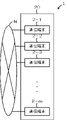
図1は、本実施形態に係る通信システムの構成例を示すブロック図である。 FIG. 1 is a block diagram showing a configuration example of a communication system according to this embodiment.
図1に示すように、通信システム1は、複数の通信端末2-m(mは自然数)を具備する。複数の通信端末2-mは、インターネット等のネットワークNを介して相互に通信可能に接続され、通信ノード、あるいは単にノードと呼ばれる。複数の通信端末(ノード)2-mは、ピア・ツウ・ピア方式で通信を行い、ピア・ツウ・ピア(P2P)型ネットワークを構成する。
As shown in FIG. 1, a
通信端末(ノード)2-mは、例えば汎用のパーソナルコンピュータ、汎用のサーバコンピュータ、若しくはタブレットコンピュータ、スマートフォン、及びデジタル家庭電化製品等のIP(Internet Protocol)通信機能を持つCPU(Central Processing Unit)を備えたスマートデバイス等から構成される。 The communication terminal (node) 2-m is a CPU (Central Processing Unit) having an IP (Internet Protocol) communication function such as a general-purpose personal computer, a general-purpose server computer, a tablet computer, a smartphone, or a digital home appliance. It consists of smart devices, etc. equipped with
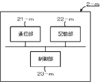
図2は、通信端末の構成例を示すブロック図である。 FIG. 2 is a block diagram showing a configuration example of a communication terminal.
図2に示すように、通信端末(ノード)2-mは、それぞれ、通信部21-mと、記憶部22-mと、制御部23-mと、を備え、これらはバス等を介して接続される。 As shown in FIG. 2, each communication terminal (node) 2-m includes a communication unit 21-m, a storage unit 22-m, and a control unit 23-m. Connected.
通信部21-mは、例えば無線通信装置等から構成される。通信部21-mは、他の通信端末(ノード)2-mとネットワークNを介したデータの送受信を行う。 The communication unit 21-m is composed of, for example, a wireless communication device. The communication unit 21-m performs data transmission/reception via the network N with another communication terminal (node) 2-m.
記憶部22-mは、例えば汎用のフラッシュメモリ等の不揮発性メモリ等から構成される。記憶部22-mは、プロパティを管理するテーブル等を保持(記憶)する。プロパティは、通信端末(ピア)2-mのユーザを特定するためのユーザID(Identification)に対応付けて、ドメイン及びドメインIDに加え、対象ノードとの関係(親ノード又は子ノード)、対象ノードのユーザID及びドメインID、スコープを必須で管理する他、信用定数や、IPアドレスポートなどのアクセスに関するパラメータ(以下、「接続情報」という。)を記憶部22-mに登録する。ここで、ユーザIDは、例えば32バイトのバイナリデータから構成される。「親ノード」とは、自己が所属する接続グループの親(グループオーナ)の通信端末(ノード)2-mをいう。「子ノード」とは、自己が親(グループオーナ)であるグループに所属する通信端末(ノード)2-mをいう。IPアドレス等の接続情報には、自己との接続に必要な接続情報と、親ノードや子ノードとの接続に必要な接続情報と、が含まれる。親ノードや子ノードとの接続に必要な接続情報は、親ノードや子ノードのユーザIDに対応付けてプロパティに登録されている。記憶部22-mには、通信端末2-m間の論理的経路(通信経路)を形成するためのアプリケーションプログラム(以下、「経路形成アプリ」という。)がインストールされている。 The storage unit 22-m is composed of a non-volatile memory such as a general-purpose flash memory. The storage unit 22-m holds (stores) a table or the like for managing properties. The property is associated with the user ID (Identification) for specifying the user of the communication terminal (peer) 2-m, and in addition to the domain and domain ID, the relationship with the target node (parent node or child node), the target node In addition to managing the user ID, domain ID, and scope of each, parameters (hereinafter referred to as "connection information") related to access such as credit constants and IP address ports are registered in the storage unit 22-m. Here, the user ID is composed of, for example, 32-byte binary data. A “parent node” is a communication terminal (node) 2-m that is the parent (group owner) of the connection group to which it belongs. A "child node" is a communication terminal (node) 2-m belonging to a group of which the self is a parent (group owner). The connection information such as the IP address includes connection information necessary for connection with itself and connection information necessary for connection with parent nodes and child nodes. Connection information necessary for connection with parent nodes and child nodes is registered in properties in association with user IDs of parent nodes and child nodes. An application program for forming a logical route (communication route) between the communication terminals 2-m (hereinafter referred to as “route forming application”) is installed in the storage unit 22-m.
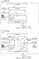
図3Aは、通信端末のOSがLinux(登録商標)の場合の経路形成アプリの構成を示す図であり、図3Bは、通信端末のOSがAndroid(登録商標)の場合の経路形成アプリの構成を示す図である。 FIG. 3A is a diagram showing the configuration of the route forming application when the OS of the communication terminal is Linux (registered trademark), and FIG. 3B is the configuration of the route forming application when the OS of the communication terminal is Android (registered trademark). It is a figure which shows.
図3Bにように、経路形成アプリは、接続グラフ、多重認証グラフ(アプリグラフ)、及びユーザグラフ等を備える。 As shown in FIG. 3B, the path formation application includes a connection graph, a multiple authentication graph (application graph), a user graph, and the like.
接続グラフは、接続ノードのグラフであって、参加者を組織する基礎的なグラフである。ユーザIDを有する通信端末2-mは、100%属している。 A connection graph is a graph of connection nodes, the underlying graph that organizes the participants. A communication terminal 2-m having a user ID belongs to 100%.
アプリグラフは、特定のアプリ利用者が属するグラフである。 An application graph is a graph to which specific application users belong.
ユーザグラフは、経路形成アプリ内でのチャットグループや、フォロー、友達登録などユーザが任意で作成するグラフである。 The user graph is a graph arbitrarily created by the user, such as a chat group within the route formation application, follow-up, and friend registration.
図2に示す制御部23-mは、例えばCPU、ROM(Read Only Memory)、及びRAM(Random Access Memory)等から構成される。CPUは、RAMをワークメモリとして用い、ROM及び記憶部22に記憶されているプログラム等を適宜実行することによって、通信端末(ノード)2-mの各種動作を制御する。
The control unit 23-m shown in FIG. 2 is composed of, for example, a CPU, a ROM (Read Only Memory), a RAM (Random Access Memory), and the like. The CPU uses the RAM as a work memory and appropriately executes programs and the like stored in the ROM and
本実施形態において、制御部23-mは、記憶部22に記憶されている経路形成アプリを実行することにより、グラフを使用して、通信端末2-m間の論理的経路を形成する。ここで、グラフは、通信端末(ノード)2-mの他、以下に定義するノード、エッジ、プロパティ、及びメソッドから構成され、いわゆるプロパティグラフモデルの一種である。
In the present embodiment, the control unit 23-m uses the graph to form a logical route between the communication terminals 2-m by executing a route forming application stored in the
ノードは、点や丸で表現されるエンティティで、「ラベル」を付けて種別を分類する。本実施形態では、「ラベル」を「プロパティ」と呼ぶ。また、ノードは、何らかの形でネットワークNにつながっていて、データがやりとりされる主体の総称をいい、スマートフォンやコンピュータ等の物理的な通信端末の他、ユーザや法人、近隣など抽象概念もノードとして取り扱ってもよい。特に本実施形態に係るルールを解して振舞うノードをピアと呼ぶ。すなわち、ピアは、特定のプロトコル(自然言語を含む)を理解し、特定のコンテキストで閉じた関係のあるノードをいう。ユーザIDを有するピアは、本実施形態に係るプロトコルを話すノードをいう。応用例として、本実施形態に係る英語ピアは、本実施形態に係る通信システム1に参加していて英語を理解するノードをいう。広義には操作している人間を含む。直接関係のあるユーザIDを有するピア同士は必ず親子関係が存在する。ノードは、属性を表す「プロパティ」の他、メソッドと呼ばれる機能を持つ。メソッドは、経路形成アプリに組み込まれた機能で、常駐する通信システム1そのものが関与するものではない。特殊なケースとして認証やルーティングに関する機能(メソッド)は、経路形成アプリに組み込まれた機能と見做す。
A node is an entity represented by a dot or a circle, and is assigned a "label" to classify its type. In this embodiment, "label" is called "property". Also, a node is a general term for entities that are connected to the network N in some way and data is exchanged. In addition to physical communication terminals such as smartphones and computers, abstract concepts such as users, corporations, and neighborhoods can also be considered nodes. may be handled. In particular, a node that behaves according to the rules according to this embodiment is called a peer. That is, a peer refers to a node that understands a particular protocol (including natural language) and has a closed relationship in a particular context. A peer with a user ID refers to a node that speaks the protocol according to this embodiment. As an application example, an English peer according to this embodiment refers to a node that participates in the
エッジは、通信端末(ノード)2-m間の関係性を表すものである。エッジには、親子の一親等の関係として、必ず、方向、属性(ドメイン)、並びに開始ノードとなる子ノード又は終了ノードとなる親ノードがあり、宙ぶらりんの関係はない。エッジは、子ノードとなる通信端末(ノード)2-mが管理するプロパティによって定義され、振舞いが決まる。エッジの方向と属性とは、それぞれノードの構造とメソッドの取扱とを明示する。 An edge represents a relationship between communication terminals (nodes) 2-m. An edge always has a direction, an attribute (domain), and a child node serving as a start node or a parent node serving as an end node as a parent-child first-degree relationship, and there is no dangling relationship. An edge is defined by properties managed by a communication terminal (node) 2-m, which is a child node, and its behavior is determined. Edge directions and attributes specify node structure and method handling, respectively.
プロパティは、通信端末(ノード)2-m及びエッジにおける属性情報であり、通信端末(ノード)2-mが、記憶部22-mに記憶されるテーブルで管理する。また、通信端末(ノード)2-mは、属性情報をkey/value形式のデータに整理し、台帳として共有保持してもよい。 The property is attribute information of the communication terminal (node) 2-m and edge, and managed by the communication terminal (node) 2-m in a table stored in the storage unit 22-m. Also, the communication terminal (node) 2-m may organize the attribute information into key/value format data and share and hold it as a ledger.
メソッドは、他の通信端末(ノード)2-mからの起動要求(例えば通信開始コマンドや経路形成コマンド等)に応じて実行されるものである。通信端末(ノード)2-mは、メソッドを実行に際して、必ず一親等直上の親ノードに戻り値を返して終了する。また、通信端末(ノード)2-mは、直接親子関係のある子ノードに対して、同じメソッドを起動させることができる。 A method is executed in response to an activation request (for example, a communication start command, a path formation command, etc.) from another communication terminal (node) 2-m. When executing the method, the communication terminal (node) 2-m always returns a return value to the immediate parent node of the first degree of kinship and terminates. Also, the communication terminal (node) 2-m can activate the same method for child nodes that have a direct parent-child relationship.
ここで、親子関係を持つ通信端末(ノード)2-m間で親ノードが子ノードに対して発行する起動要求を「コマンド」と呼び、親でない通信端末(ノード)2-mが発行する起動要求を「アテンション(喚起)」と呼んで区別する。コマンド又はアテンション(喚起)が発せされると、必ずそのコマンド又はアテンション(喚起)の戻り値は、当該ドメインの親ノードとなる通信端末(ノード)2-mに返される。コマンド又はアテンション(喚起)は、その戻り値のベクトルがエッジと一致するので、通信端末(ノード)2-mをつないだ構造化に準じる。 Here, an activation request issued by a parent node to a child node between communication terminals (nodes) 2-m having a parent-child relationship is called a "command", and an activation request issued by a non-parent communication terminal (node) 2-m is called a "command". Requests are distinguished by calling them "attentions". When a command or attention (calling) is issued, the return value of the command or attention (calling) is always returned to the communication terminal (node) 2-m which is the parent node of the domain. A command or attention (arousal) conforms to the structuring that connects the communication terminals (nodes) 2-m because the vector of the return value matches the edge.
本実施形態に係る通信システム1は、リレー接続を担う通信端末(ノード)2-mを明示することで論理的に経路を構築している。物理的な経路の制限を受けずに経路を増やすことができ、指定する経路の信頼性や性能の定量的な評価も可能である。この際、ネットワークNの物理的接続と、経路形成アプリが持つ通信端末(ノード)2-m間の関係と、を統合したグラフとして取り扱うと多くのメリットがあることが知られている。しかし、これには、分析にかかる計算量が増大し、グラフデータベースによるルーティングを実現するためには、新たな工夫が必要である。IoT(Internet of Things)のアプリケーションでは、500億ノードといわれる膨大な数のノードのネットワーク上で、非力な演算能力しか持たないものを含めて、パフォーマンスを落とさずに結果を返すことが求められる。したがって、本実施形態に係る通信システム1は、単純なルールをもって、個々の通信端末(ノード)2-mの演算を限定的で小さくまとめ、グラフデータを分散したまま、ネットワークN上の通信端末(ノード)2-mに分散連携してクエリやそのほかの機能を実行する。
The
本実施形態に係るグラフの定義を以下、箇条書きにする。 The definition of the graph according to this embodiment will be itemized below.
定義1.子→親:一親等制限をグラフの単位とする。
グラフにおける子ノードとなる通信端末(ノード)2-mの制御部23-mは、エッジに沿って、親ノードとなる通信端末(ノード)2-mにイベントの報告をする。具体的には、コマンドの戻り値の流れで有向グラフを形成する。
The control unit 23-m of the communication terminal (node) 2-m, which is a child node in the graph, reports an event to the communication terminal (node) 2-m, which is a parent node, along the edge. Specifically, the flow of command return values forms a directed graph.
定義2.通信端末(ノード)2-mには、プロパティが設定される。通信端末(ノード)2-mは、当該通信端末(ノード)2-m直上の親ノードと、当該通信端末(ノード)2-m直下の子ノードと、をプロパティとして管理する。通信端末(ノード)2-mは、ドメイン、ユーザID、及びドメインIDに加え、対象ノードとの関係(親ノード又は子ノード)、対象ノードのユーザID及びドメインID、スコープを必須で管理する他、信用定数やIPアドレスポートなどのアクセスに関するパラメータを記憶部22-mに保持する。
定義3.通信端末(ノード)2-mは、経路形成アプリが予め定義する機能を持ち、これをメソッドと呼ぶ。
定義4.他の通信端末(ノード)2-mからのメソッドの起動要求は、起動要求を発行する他の通信端末(ノード)2-mのプロパティ、起動要求するメソッド、及び起動要求固有のシリアル番号等をもって発行することができる。
定義5.メソッドの起動要求を受けた通信端末(ノード)2-mの制御部23-mは、プロパティが定義するスコープに応じて(起動要求を無視したり、メソッドの起動要求の拒否を含めて)対処する。メソッドの起動要求を受けると、通信端末(ノード)2-mの制御部23-mは、起動要求の持つドメイン直上の親ノードに戻り値を返す。 Definition 5. The control unit 23-m of the communication terminal (node) 2-m that has received the method activation request takes action according to the scope defined by the property (including ignoring the activation request and rejecting the method activation request). do. Upon receiving the method activation request, the control unit 23-m of the communication terminal (node) 2-m returns a return value to the parent node immediately above the domain of the activation request.
本実施形態に係るグラフは、通信端末(ノード)2-m間の関係を記述する。通信端末(ノード)2-mに常駐するグラフマネージャは、他の通信端末(ノード)2-mからメソッドの起動要求を受けて、戻り値を発行する。本実施形態では、この戻り値の流れを矢印で記述する。また、この矢印をもって、通信端末(ノード)2-mの従属関係(親子関係)を整合する。すなわち、「ノード(A)はノード(C)に属する」という関係は、ノード(C)を親ノードとしてノード(A)を従属させる。例えばノード(C)がノード(A)に要求コマンド(例えば経路形成コマンド等)を発すると、ノード(A)は、ノード(C)に戻り値を返す。通信端末(ノード)2-mは、他のノード(パブリック、ドメイン、プライベート)が持つのメソッド(“関数”)に対して、ユニークなコマンドID(自らのユーザID、コマンドシリアルから生成)と起動を継承する深さとを指定してグラフに関するメソッド(処理関数)を起動する。子ノードに対して起動した関数の戻り値をもって終了する。直接の子ノードではない通信端末(ノード)2-mに対してアテンション(喚起)を発呼しても、戻り値は、発呼した通信端末(ノード)2-mには帰らず、メソッドを実行した通信端末(ノード)2-mの直接の親ノードに戻り値が報告されることに注意を要する。コマンド及びアテンション(喚起)には、R.U.P.A.D.という5つの引数があり、関連性(Relation)、緊急性(Urgency)、優先度(Priority)、結合性(Association)、及び委託深度(Depth)をリザーブされたキーを持つ。 The graph according to this embodiment describes the relationship between the communication terminals (nodes) 2-m. A graph manager residing in the communication terminal (node) 2-m receives a method activation request from another communication terminal (node) 2-m and issues a return value. In this embodiment, the flow of this return value is described by arrows. Also, with this arrow, the subordinate relationship (parent-child relationship) of the communication terminal (node) 2-m is matched. That is, the relationship "node (A) belongs to node (C)" subordinates node (A) to node (C) as a parent node. For example, when node (C) issues a request command (such as a route creation command) to node (A), node (A) returns a return value to node (C). A communication terminal (node) 2-m activates a unique command ID (generated from its own user ID and command serial) for methods ("functions") possessed by other nodes (public, domain, private). Invoke the graph-related method (processing function) by specifying the depth and inheritance of the . Terminate with the return value of the function invoked for the child node. Even if an attention is called to the communication terminal (node) 2-m that is not a direct child node, the return value is not returned to the communication terminal (node) 2-m that called, and the method is called. Note that the return value is reported to the immediate parent node of the communication terminal (node) 2-m that executed. For commands and attentions, R.I. U.S.A. P. A. D. with reserved keys Relation, Urgency, Priority, Association, and Depth of Delegation.
以下、定義に従って、実装ルールを説明する。 The implementation rules are explained below according to the definitions.
(実装ルール1)
グラフは、コマンドの戻り値の流れで有向グラフを形成する。 実装ルール1の目的は、コマンドと戻り値との流れを制限することで、親ノードとなる通信端末(ノード)2-mにグラフの管理権限を持たせることにある。(Implementation rule 1)
The graph forms a directed graph with the flow of command return values. The purpose of
グラフは、通信端末(ノード)2-m間の関係を記述する。通信端末(ノード)2-mに常駐するグラフマネージャは、他の通信端末(ノード)2-mからのコマンド(破線→)を受けて、戻り値を発行する。この戻り値の流れを矢印で記述する。 The graph describes the relationships between communication terminals (nodes) 2-m. A graph manager residing in the communication terminal (node) 2-m receives a command (broken line→) from another communication terminal (node) 2-m and issues a return value. The flow of this return value is described with an arrow.
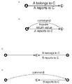
図4は、実装ルール1の説明図である。
FIG. 4 is an explanatory diagram of
図4Aに示すように、「ノード(A)はノード(C)に属する」という関係は、ノート(C)を親ノードとしてノード(A)を従属させる。例えば、図4Bに示すように、ノード(C)がノード(A)にコマンドを発すると、ノード(A)は、ノード(C)に戻り値を返す。この際、ノード(A)は、直上の親ノード(C)限定でコマンドを受付ける。 As shown in FIG. 4A, the relationship "node (A) belongs to node (C)" subordinates node (A) to node (C) as the parent node. For example, as shown in FIG. 4B, when node (C) issues a command to node (A), node (A) returns a return value to node (C). At this time, node (A) accepts commands only for the immediate parent node (C).
この際、ノード(A)は、直上の親ノード(C)限定でコマンドを受付るが、それ以外の通信端末(ノード)2-mからの処理の要求は、アテンション(喚起)として処理する。例えば、図4Cに示すように、上記「ノード(A)はノード(C)に属する」という関係に加えて、ノード(C)を親としてノード(B)を従属させる。ノード(C)がノード(B)にコマンドを発すると、ノード(B)はノード(C)に戻り値を返す。 At this time, the node (A) accepts commands only for the immediate parent node (C), but processes requests for processing from other communication terminals (nodes) 2-m as attentions. For example, as shown in FIG. 4C, in addition to the relationship "node (A) belongs to node (C)", node (C) is the parent and node (B) is subordinated. When node (C) issues a command to node (B), node (B) returns a return value to node (C).
図4Dに示すように、ノード(A)がノード(B)に起動要求を発すると、ノード(B)は、これを「アテンション(喚起)」として扱い、処理を実行してもノード(A)にではなく、ノード(C)に戻り値を返す。 As shown in FIG. 4D, when node (A) issues an activation request to node (B), node (B) treats this as an “attention” and even if node (A) executes the process, Returns a return value to node (C) instead of to .
子ノードは、グラフの文脈やドメイン・スコープが一致しても起動要求の起源が親ノードでない場合、仮に処理を発動しても、親ノードからの起動要求では無い場合、これを受け付けない。発呼された起動要求はあくまでアテンション(喚起)として処理される。 Even if the context and domain scope of the graph match, if the origin of the activation request is not the parent node, even if the child node activates the process, if the activation request is not from the parent node, it will not be accepted. The initiated activation request is treated as an attention (awakening).
(実装ルール2)
通信端末(ノード)2-mの制御部23-mによる検索は、直接探索に限定し、2親等以上の探索は、委託に限定し直接探索は行わない。実装ルール2の目的は、探索計算の負荷を分散させるとともに、委託探索の方法を定義し、ネットワークNが不要な探索でリソースを浪費することを回避するために、既知の通信端末(ノード)2-mからの報告を安全に逆上させる方法を持たせることにある。(Implementation rule 2)
The search by the control unit 23-m of the communication terminal (node) 2-m is limited to direct search, and the search of second degree or higher is limited to entrustment and direct search is not performed. The purpose of
図5は、実装ルール2の説明図である。
FIG. 5 is an explanatory diagram of
図5に示すように、ノード(L)を親としてノード(C)を従属させると、ノード(L)がノード(C)に対して発する起動要求(コマンド)の戻り値は、ノード(L)に帰る。ノード(L)がノード(B)に対して発する起動要求は、アテンション(喚起)として解され、その戻り値は、必ず直上の親ノード(C)に報告される。ノード(C)は、ノード(B)からの戻り値を受けて直上の親ノード(L)に報告される。既知の通信端末(ノード)2-mの系統を見出す時に用いる。 As shown in FIG. 5, when node (L) is the parent and node (C) is subordinated, the return value of the activation request (command) issued by node (L) to node (C) is go back to An activation request issued by node (L) to node (B) is interpreted as an attention (arousal), and its return value is always reported to the immediate parent node (C). Node (C) receives the return value from node (B) and reports it to the immediate parent node (L). It is used when finding the system of a known communication terminal (node) 2-m.
探索の対象が一親等を超える位相に存在する場合、直下のメンバーの通信端末(ノード)2-mに委託して探索する。このルールは、膨大なグラフを探索する際に発生する負荷を軽減させ探索速度を向上させること、セキュリティを担保することといった二つの効果をもたらす。 If the object of search exists in a phase exceeding the first degree of kinship, the search is entrusted to the communication terminal (node) 2-m of the member immediately below. This rule has two effects: reducing the load generated when searching a huge graph, improving search speed, and ensuring security.
(実装ルール3)
本実施形態に係るグラフは、オーバーレイをドメインという概念をプロパティとして構成する。グラフでは、通信端末(ノード)2-mのプロパティとして“ドメイン”をアサインする。ここで、ドメインとしてユーザIDを持つ全ての通信端末(ノード)2-mが参加する接続グラフと、経路形成アプリを含む上位レイヤが定義するオーバーレイグラフと、が存在する。したがって、接続グラフという“オーバーレイグラフ”は、 通信システム1をアプリケーションプログラムと見立ててオーバーレイグラフの一種と見ることで、統一したルールでグラフを扱う。(Implementation rule 3)
The graph according to this embodiment configures the concept of a domain as a property of an overlay. In the graph, "domain" is assigned as a property of the communication terminal (node) 2-m. Here, there is a connection graph in which all communication terminals (nodes) 2-m having user IDs as domains participate, and an overlay graph defined by an upper layer including a route forming application. Therefore, the "overlay graph", which is a connection graph, treats the graph according to a unified rule by regarding the
ここで、ドメインは、単位グラフのオーバーレイの名称である。スコープは、閲覧範囲、コマンド・アテンション(喚起)の受付範囲である。スコアは、子ノードに対する評価パラメータである。 Here, domain is the name of the unit graph overlay. The scope is the reading range and the receiving range of command attention (evoke). A score is an evaluation parameter for a child node.
(実装ルール4)
本実施形態に係るグラフは、離散グラフを持つ。実装ルール4の目的は、ユーザIDを有する通信端末(ノード)2-mが存在しないネットワークや、グローバルなインターネットから隔離されたイントラネットに限定して、本実施形態に係る通信システム1を実装する方法を定義する。(Implementation rule 4)
The graph according to this embodiment has a discrete graph. The purpose of the
図6は、実装ルール4の説明図である。
FIG. 6 is an explanatory diagram of
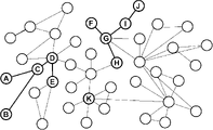
同一ドメインないであっても、エッジを辿って結ばれていない離散ノードが存在する場合がある。図6に示すように、離散ノードは、ノード(K)のように単独で存在する場合もあれば、ノード(A)-ノード(B)-ノード(C)-ノード(D)-ノード(E)、ノード(F)-ノード(G)-ノード(H)-ノード(I)-ノード(J)のように、エッジを辿って結ばれた通信端末(ノード)2-mが複数のコロニーを形成してコロニー間を結ぶエッジが存在しない場合もある。離れ小島になった通信端末(ノード)2-mやコロニーを離散グラフと呼ぶ。離散グラフの処理は、ドメインと目的をベースにして、スコープのキーにアサインされた値で制限をかける。 Even if they are not in the same domain, there may be discrete nodes that are not connected by tracing edges. As shown in FIG. 6, a discrete node may exist alone like node (K), or may be node (A)-node (B)-node (C)-node (D)-node (E ), node (F)-node (G)-node (H)-node (I)-node (J). There may be no edges that form and connect between colonies. A communication terminal (node) 2-m or a colony that has become an isolated small island is called a discrete graph. Discrete graph processing is based on domain and purpose and is constrained by values assigned to scope keys.
通信端末(ノード)2-mを新設した場合、新たな経路形成アプリを設定して、他のコロニーとの通信が確立せず、やむを得ず、孤島のような通信端末(ノード)2-mを加えたときには、通信が確立次第、以下のケースに基づいて処理をする。 When a communication terminal (node) 2-m is newly installed, a new route formation application is set, and communication with other colonies cannot be established. When communication is established, processing is performed based on the following cases.
(実装ルール5)
本実施形態に係るグラフの通信端末(ノード)2-mは、他のユーザIDを有する通信端末(ノード)2-mからの起動要求で起動するメソッドまたは関数(コマンド)を持つ。実装ルール1により、起動要求を発信する通信端末(ノード)2-mが起動要求を受ける通信端末(ノード)2-mの親であり、これが管理するグラフ関係を持つユーザIDを有する通信端末(ノード)2-mであることを必要条件として起動させるメソッドまたは関数は、ドメインが一致していることをパブリックメソッド、またはパブリック関数と呼ぶ。この際、ドメインを指定して制限をかけることもできる。ドメインは、外部が1親等の親ノードであることを必要条件として起動させるメソッドまたは関数をプライベートメソッドまたはプライベート関数と呼ぶ。自らを親ノードとする子ノードに対してユニークな委託IDを振ったメソッドまたは関数機能を委託することができる。メソッドまたは関数機能の戻り値は、親ノードに返す。委託を受けた子ノードは、自らを親ノードとする子ノード、すなわち祖ノードから見ると孫ノードに対して通信端末(ノード)2-m間の関係を記述する。ユーザIDを有する通信端末(ノード)2-mに常駐するグラフマネージャは、他の通信端末(ノード)2-mからのコマンド(破線→)を受けて、戻り値を発行する。この戻り値の流れを矢印で記述する。(Implementation rule 5)
A communication terminal (node) 2-m in the graph according to this embodiment has a method or function (command) that is activated by an activation request from a communication terminal (node) 2-m having another user ID. According to
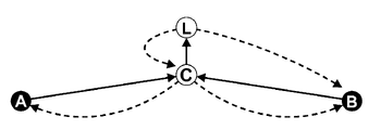
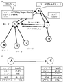
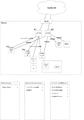
図7は、実装ルール5の説明図である。 FIG. 7 is an explanatory diagram of implementation rule 5. As shown in FIG.
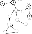
図7に示すように、ノード(L)は、ノード(B)を探索する際、まず、ノード(L)を親ノードとする直下に位置する通信端末(ノード)2-mのリストからノード(B)を探索する。上記の図のような位相になっている場合、当然ノード(L)のリストには、ノード(B)が存在しないので、探索の委託を直下に位置にする通信端末(ノード)2-m群に、この場合はノード(C)に対してノード(B)の探索を委託する。ノード(C)が持つノード(C)を親ノードとするメンバーリストにノード(B)が存在するので、ノード(C)は、ノード(B)に対してコマンドを発する。ノード(B)は、そのコマンドの戻り値をノード(C)に返す。ノード(C)は、ノード(C)に対してコマンドを発したノード(L)に対してノード(B)から受け取った戻り値をノード(C)の戻り値の一部として返す。一見、無駄な作業に見えるが、各通信端末(ノード)2-mが親ノードとして、その直下に10個の通信端末(ノード)2-mを管理していると、あるコマンドに対して非力なマイクロコンピュータでも通信時間を含めて100ミリ秒で処理が終わる。10親等の処理で1010個の通信端末(ノード)2-m、すなわち一秒間で10,000,000,000=100億個の通信端末(ノード)2-mの探索が可能である。これにより、本実施形態に係る通信システム1は、通信経路の形成の高速化を実現することができる。
As shown in FIG. 7, when searching for a node (B), a node (L) first selects a node ( B) is explored. If the phase is as shown in the figure above, the node (B) naturally does not exist in the list of the node (L). In this case, node (C) is commissioned to search for node (B). Since node (B) exists in the member list held by node (C) and having node (C) as a parent node, node (C) issues a command to node (B). Node (B) returns the return value of the command to node (C). The node (C) returns the return value received from the node (B) to the node (L) that issued the command to the node (C) as part of the return value of the node (C). At first glance, this seems like a waste of work, but if each communication terminal (node) 2-m is a parent node and manages 10 communication terminals (nodes) 2-m directly under it, it will be powerless to respond to a certain command. Even a small microcomputer completes processing in 100 milliseconds including communication time. It is possible to search 1010 communication terminals (nodes) 2-m with 10 degree processing, that is, 10,000,000,000 = 10 billion communication terminals (nodes) 2-m per second. As a result, the
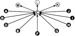
図7に示す例では、ノード(C)を頂点とするグラフをリストしている。ノード(A),(B),(D),(E),(F),(G),(H),(I),及び(J)は、ノード(C)に帰属し、同時にノード(C)は、ノード(K),(L),及び(M)に帰属する。ここでは、一方向の戻り値の矢印を描いているが、それぞれ一方向に上り、下りでループになっている場合も考えられる。 In the example shown in FIG. 7, a graph with node (C) as a vertex is listed. Nodes (A), (B), (D), (E), (F), (G), (H), (I), and (J) belong to node (C), and at the same time node ( C) belongs to nodes (K), (L) and (M). Here, a one-directional return value arrow is drawn, but it is also conceivable that the return value goes up in one direction and loops down.
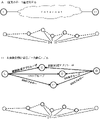
図8は、コマンドのループを例示する説明図である。 FIG. 8 is an explanatory diagram illustrating a command loop.
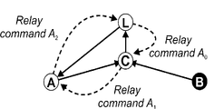
例えば、図8に示すように、ノード(A)がノード(C)を親ノードとするグラフ(コミュニティ)の子ノードであり、ノード(C)がノード(L)を親ノードとするグラフの子ノードで、なおかつノード(L)がノード(A)を親ノードとするグラフの子ノードである場合、ノード(L)がノード(C)に対して起動要求(委託探索(経路形成コマンド))Relay command A0を発令すると、ノード(C)は、ノード(A)に対して起動要求(委託探索)Relay command A1を発令し、ノード(A)がノード(L)に対して起動要求(委託探索)Relay command A2を発令する。起動要求(委託探索)などのリレーされるコマンドは、全体として無限ループを発生するので、同じコマンドを繰り返し重複処理しないように、リレーするコマンドに委託探索のID(例えば、最初にコマンドを発呼したノード(以下、「原始発呼ノード」という。)のユーザID及びコマンドシリアル等)を持たせて、これを根拠にループを切断すればよい。また、コマンドを発呼する際に、委託の深さとドメインとを指定して、探索に制限をかけてもよい。 For example, as shown in FIG. 8, node (A) is a child node of a graph (community) whose parent node is node (C), and node (C) is a child node of a graph whose parent node is node (L). node, and node (L) is a child node of a graph with node (A) as the parent node, node (L) requests node (C) to start (delegated search (route formation command)) Relay When command A0 is issued, node (C) issues an activation request (delegated search) Relay command A1 to node (A), and node (A) issues an activation request (delegated search) to node (L). Issue Relay command A2. Relayed commands such as activation requests (delegated search) generate an infinite loop as a whole. The user ID, command serial number, etc. of the node (hereinafter referred to as the "primitive calling node") is provided, and the loop can be cut based on this. Also, when issuing a command, the depth of entrustment and the domain may be specified to limit the search.
(プロパティの構造と予約キー)
単位グラフは、当該通信端末(ノード)2-mのプロパティとして管理する。以下、ユーザIDを有する通信端末(ノード)2-mの実装例で、当該通信端末(ノード)2-mが管理するプロパティのレコードの内容を箇条書きで掲載する。(property structure and reserved keys)
A unit graph is managed as a property of the communication terminal (node) 2-m. In the following, an implementation example of a communication terminal (node) 2-m having a user ID will be itemized with the contents of property records managed by the communication terminal (node) 2-m.
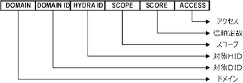
図9は、プロパティの構成例を示す図である。 FIG. 9 is a diagram showing a configuration example of properties.
図9に示すように、プロパティは、ドメイン(Domain)、ドメインID(Domain ID)、ユーザID(HYDRA ID)、スコープ(Scope)、スコア(Score)、及びアクセス(Access)等を含む。なお、プロパティは、リアルノード及びバーチャルノードのいずれかを示すピアタイプを含んでもよい。バーチャルノードは、センサなど、本実施形態に係るプロトコルを話さないが、ユーザIDを有する通信端末(リアルノード)2-mの手足として便宜上ユーザIDを取得している通信端末(リアルノー
)2-mである。As shown in FIG. 9, the properties include Domain, Domain ID, User ID (HYDRA ID), Scope, Score, Access, and the like. Note that the properties may include a peer type indicating either a real node or a virtual node. A virtual node is a communication terminal (real node) 2-m that does not speak the protocol according to the present embodiment, such as a sensor, but acquires a user ID for convenience as a limb of a communication terminal (real node) 2-m that has a user ID. is.
ドメイン(Domain)は、当該単位グラフを規定する経路形成アプリが定義するドメインであって、具体的に、通信端末(ノード)2-mの所属に関する階層的データ(例えば、家庭内ネット、照明機器、及びリモートコントローラ等)である。 A domain is a domain defined by a route forming application that defines the unit graph. , and remote controllers, etc.).
ドメインID(Domain ID)は、当該ドメインにおける管理対象の通信端末(ノード)2-mのドメインIDである。 The domain ID (Domain ID) is the domain ID of the communication terminal (node) 2-m to be managed in the domain.
ユーザID(HYDRA ID)は、管理対象の通信端末(ノード)2-mのユーザIDである。 The user ID (HYDRA ID) is the user ID of the communication terminal (node) 2-m to be managed.
スコープ(Scope)は、誰が何をどこまで見えるかについてのデータであって、閲覧範囲、コマンド・アテンション(喚起)の受付範囲を示し、管理対象の通信端末(ノード)2-mの情報開示範囲を、公開(Public)、非公開(Private)、及びドメイン(Domain)のいずれかに定義するものである。公開(Public)は、誰でも閲覧できることを示し、非公開(Private)は、自分だけで子ノードに継承しないことを示し、ドメイン(Domain)は、誰が子ノードに継承するかを示す。例えば、ドメイン(Domain)は、ドメインが一致すれば、公開し、親ノードは、子ノードに対して、子ノードの子ノード(孫ノード)にメソッド(関数)の委託を継承することができる。 Scope is data about who can see what and to what extent, and indicates the range of viewing, the range of acceptance of command attention (evoke), and the range of information disclosure of the communication terminal (node) 2-m to be managed. , Public, Private, and Domain. "Public" indicates that anyone can view the information, "Private" indicates that the child node does not inherit the information by itself, and "Domain" indicates who inherits the information to the child nodes. For example, a Domain can publish if the domains match, and a parent node can inherit the delegation of methods (functions) to the child node's child nodes (grandchild nodes).
スコア(Score)は、親ノードが子ノードを評価する指標を示し、管理対象ノードの信頼定数を、Parent, Value, RUPAD, 及びNeuralのいずれかに定義するものである。ここで、Parentは、管理対象の通信端末(ノード)2-mが当該ドメインの親ノードである。Valueは、対象の子ノードの信頼定数である。RUPADは、処理を含めた接続強度の配列である。Neuralは、結合処理を含めた接続強度の配列である。 The score (Score) indicates an index by which the parent node evaluates the child node, and defines the trust constant of the managed node as one of Parent, Value, RUPAD, and Neural. Here, Parent indicates that the communication terminal (node) 2-m to be managed is the parent node of the domain. Value is the confidence constant of the child node of interest. RUPAD is an array of connection strengths including treatments. Neural is an array of connection strengths including connection processing.
アクセス(Access)は、管理対象の通信端末(ノード)2-mへの直接接続の方法を定義するものである。アクセス(Access)は、動的に変化するが、IPアドレス+ポートや、TURN(Traversal Using Relay around NAT)等の経由サービスのアクセス情報を記載する。 Access defines a method of direct connection to the managed communication terminal (node) 2-m. Access, which dynamically changes, describes access information for transit services such as IP address + port and TURN (Traversal Using Relay around NAT).
プロパティは、単位グラフを定義し、当該通信端末(ノード)2-mがプロパティとしてローカルに管理する。ユーザIDを有する通信端末(ノード)2-mの実装で、この情報を純粋にローカルにおいてのみ保存しておくより、バックアップとしてネットワーク上に分散管理するメリットが大きい。キーヴァリュー方式による分散ハッシュテーブル(Distributed Hash Table, DHT)による分散管理の例を記載する。 A property defines a unit graph and is locally managed by the communication terminal (node) 2-m as a property. In implementation of a communication terminal (node) 2-m having a user ID, distributed management over a network as a backup is more advantageous than storing this information purely locally. An example of distributed management by a distributed hash table (DHT) based on the key-value method will be described.
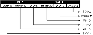
図10は、DHTによる分散管理を例示する説明図である。 FIG. 10 is an explanatory diagram illustrating distributed management by DHT.
KEYとなるデータは、ドメイン、親ノードのユーザID(親HID(HYDRA ID))、及びスコープの組み合わせで、DHTのハッシュインデックスを作成する。 The KEY data is a combination of the domain, parent node user ID (parent HID (HYDRA ID)), and scope to create a DHT hash index.
ドメイン(Domain)は、当該単位グラフを規定する経路形成アプリが定義するドメインである。 A domain (Domain) is a domain defined by a route forming application that defines the unit graph.
親ノードのユーザID(親HID(HYDRA ID))は、当該通信端末(ノード)2-mのユーザIDである。 The user ID of the parent node (parent HID (HYDRA ID)) is the user ID of the communication terminal (node) 2-m.
スコープ(Scope)は、管理対象の通信端末(ノード)2-mの情報開示範囲を、公開(Public)、ドメイン(Domain)、及びキー(Key)のいずれかに定義するものである。ここで、ドメイン(Domain)は、ドメインが一致すれば、公開し、親ノードは、子ノードに対して、子ノードの子ノード(孫ノード)にメソッド(関数)の委託を継承することができる。キー(Key)は、非公開なグラフについて、暗号化するためのキー(鍵)を記載するものである。 Scope defines the information disclosure range of the communication terminal (node) 2-m to be managed as Public, Domain, or Key. Here, the domain (Domain) can be published if the domain matches, and the parent node can inherit the delegation of the method (function) to the child node (grandchild node) of the child node for the child node. . A key describes a key for encrypting a private graph.
VALUEとなるデータは、子ノードのユーザID(子HID(HYDRA ID))、スコア、及びアクセスの組み合わせで、ハッシュインデックスに紐づけて作成する。 Data that becomes VALUE is created by linking a hash index with a combination of a child node's user ID (child HID (HYDRA ID)), score, and access.
子ノードのユーザID(子HID(HYDRA ID))は、管理対象の通信端末(ノード)2-mのユーザIDである。 The child node user ID (child HID (HYDRA ID)) is the user ID of the communication terminal (node) 2-m to be managed.
スコア(Score)は、管理対象ノードの信頼定数を、Parent, Value, 及びRUPADのいずれかに定義するものである。ここで、Valueは、対象の子ノードの信頼定数である。RUPADは、処理を含めた接続強度の配列である。 Score defines the trust constant of a managed node to be one of Parent, Value, and RUPAD. where Value is the confidence constant of the child node of interest. RUPAD is an array of connection strengths including treatments.
アクセス(Access)は、管理対象の通信端末(ノード)2-mへの直接接続の方法を定義するものである。アクセス(Access)は、動的に変化するが、IPアドレス+ポートや、TURN(Traversal Using Relay around NAT)等の経由サービスのアクセス情報を記載する。 Access defines a method of direct connection to the managed communication terminal (node) 2-m. Access, which dynamically changes, describes access information for transit services such as IP address + port and TURN (Traversal Using Relay around NAT).
図11Aは、ノードのプロパティを例示する図であり、図11Bは、グラフとプロパティとを利用したコンテクスト(文脈)の表現を例示する図である。 FIG. 11A is a diagram illustrating node properties, and FIG. 11B is a diagram illustrating context representation using graphs and properties.
図11Bに示すように、グラフとプロパティとを利用することで、単純なデータによって複雑なコンテクスト(文脈)を表現できる。 As shown in FIG. 11B, graphs and properties can be used to express complex contexts with simple data.
図12Aは、従来のデータ通信モデルを例示する図であり、図12Bは、本実施形態に係るデータ通信モデルを例示する図である。 FIG. 12A is a diagram illustrating a conventional data communication model, and FIG. 12B is a diagram illustrating a data communication model according to this embodiment.
図12Aに示す従来のデータ通信モデルにおいて、インターネットは、始点となるノード(A)及び終点となるノード(B)だけ指定すれば間は抽象化されていて、途中経路を指定することはできない。実際に働いている誰とも知れないルータ24-mたちのことは意識しなくていい。 In the conventional data communication model shown in FIG. 12A, the Internet is abstracted if only the starting node (A) and the ending node (B) are specified, and intermediate routes cannot be specified. You don't have to be conscious of unknown routers 24-m who are actually working.
図12Bに示す本実施形態に係るデータ通信モデルにおいては、始点となるノード(A)と終点となるノード(B)以外にも接続グラフで組織されたノードが抽象化されているので、各ノードを経路として指定することで、論理的経路の多重化を実現できる。実際に働いている誰とも知れないルータ24-mたちのことはやはり意識しなくていい。論理的経路の多重化については、国際出出願PCT/JP2021/ 25226にその詳細が記載されている。なお、本明細書中にPCT/JP2021/ 25226の明細書、特許請求の範囲、図面全体を参考として取り込むものとする。 In the data communication model according to this embodiment shown in FIG. 12B, nodes organized by a connection graph are abstracted in addition to the node (A) that is the start point and the node (B) that is the end point. is specified as a route, multiplexing of logical routes can be realized. You don't have to be conscious of the unknown routers 24-m who are actually working. The multiplexing of logical paths is described in detail in International Application PCT/JP2021/25226. The entire specification, claims, and drawings of PCT/JP2021/25226 are incorporated into this specification as a reference.
次に、上記構成を備える通信システム1が実行する各種処理について図面を参照して説明する。
Next, various processes executed by the
通信端末(ノード)2-mのうちの通信端末2-12(ノード(L))において、ユーザが、データの発信先となる通信端末2-2(発信先ノード、本実施形態では「ノード(B)」)とのデータ通信を指示したことに応答して、通信システム1は、データ通信開始処理を実行する。
In the communication terminal 2-12 (node (L)) among the communication terminals (nodes) 2-m, the user selects the communication terminal 2-2 (destination node) to which data is to be sent. B)”), the
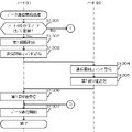
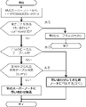
図13~図15は、データ通信開始処理の詳細を示すフローチャートである。 13 to 15 are flowcharts showing the details of data communication start processing.
図13~図15に示すデータ通信開始処理において、まず、通信端末2-12(ノード(L))の制御部23-12は、ノード(B)が、記憶部22-12に記憶されているプロパティに、ノード(L)の子ノードとして登録されているか否かを判別する(図13に示すステップS1301)。 In the data communication start processing shown in FIGS. 13 to 15, first, the control unit 23-12 of the communication terminal 2-12 (node (L)) determines that the node (B) is stored in the storage unit 22-12. It is determined whether or not the property is registered as a child node of the node (L) (step S1301 shown in FIG. 13).
ノード(B)がノード(L)の子ノードとして登録されている場合(ステップS1301;Yes)、制御部23-12は、プロパティに登録されているノード(B)の接続情報を用いて、ノード(L)とノード(B)とを直接接続する第1通信経路を形成する(ステップS1302)。 If the node (B) is registered as a child node of the node (L) (step S1301; Yes), the control unit 23-12 uses the connection information of the node (B) registered in the property to A first communication path that directly connects node (L) and node (B) is formed (step S1302).
そして、制御部23-12は、ノード(B)とのデータ通信の開始を指示する通信開始コマンドを通信部21-12から第1通信経路を介してノード(B)に送信する(ステップS1303)。 Then, the control unit 23-12 transmits a communication start command instructing the start of data communication with the node (B) from the communication unit 21-12 to the node (B) via the first communication path (step S1303). .
通信端末2-2(ノード(B))の制御部23-2は、ノード(L)から第1通信経路を介して送信される通信開始コマンドを通信部21-2で受信したことに応答して(ステップS1304)、第1戻り値を通信部21-2から第1通信経路を介して、親ノードであるノード(L)に送信する(ステップS1305)。 The control unit 23-2 of the communication terminal 2-2 (node (B)) responds to the communication start command transmitted from the node (L) through the first communication path by the communication unit 21-2. (step S1304), the first return value is transmitted from the communication unit 21-2 to the node (L), which is the parent node, via the first communication path (step S1305).
通信端末2-12(ノード(L))の制御部23-12は、ノード(B)から第1通信経路を介して送信される第1戻り値を通信部21-12で受信したことに応答して(ステップS1306)、ノード(B)とのデータ通信を開始してから(ステップS1307)、データ通信開始処理を終了する。 The control unit 23-12 of the communication terminal 2-12 (node (L)) responds to the communication unit 21-12 receiving the first return value transmitted from the node (B) via the first communication path. Then (step S1306), data communication with the node (B) is started (step S1307), and the data communication start processing is terminated.
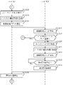
これに対して、ノード(B)がノード(L)の子ノードとして登録されていない場合(ステップS1301;No)、制御部23-12は、プロパティから、ノード(L)の子ノードとして登録(記憶部22-12に記憶)されている通信端末2-3(ノード(C))を検出する(図14に示すステップS1308)。 On the other hand, if the node (B) is not registered as a child node of the node (L) (step S1301; No), the control unit 23-12 registers it as a child node of the node (L) from the property ( The communication terminal 2-3 (node (C)) stored in the storage unit 22-12 is detected (step S1308 shown in FIG. 14).
続いて、制御部23-12は、ステップS1308で検出したノード(C)の接続情報を用いて、ノード(L)とノード(C)とを通信可能に接続する(ステップS1309)。 Subsequently, the control unit 23-12 uses the connection information of the node (C) detected in step S1308 to communicably connect the node (L) and the node (C) (step S1309).
そして、制御部23-12は、間の通信経路の形成を指示する経路形成コマンドを通信部21-12からネットワークNを介してノード(C)に送信する(ステップS1310)。経路形成コマンドには、ノード(B)のユーザID等が含まれる。 Then, the control unit 23-12 transmits a route formation command instructing formation of a communication route between them from the communication unit 21-12 to the node (C) via the network N (step S1310). The route creation command includes the user ID of node (B) and the like.
通信端末2-3(ノード(C))の制御部23-3は、ノード(L)からネットワークNを介して送信される経路形成コマンドを通信部21-3で受信したことに応答して(ステップS1311)、経路形成コマンドに含まれるユーザIDから特定されるノード(B)が、記憶部22-3に記憶されているプロパティに、ノード(C)の子ノードとして登録(記憶部22-3に記憶)されているか否かを判別する(ステップS1312)。 The control unit 23-3 of the communication terminal 2-3 (node (C)) responds to the communication unit 21-3 receiving the route formation command transmitted from the node (L) via the network N ( Step S1311), the node (B) specified by the user ID included in the path formation command is registered in the property stored in the storage unit 22-3 as a child node of the node (C) (storage unit 22-3 stored) is determined (step S1312).
ノード(B)がノード(C)の子ノードとして登録されている場合(ステップS1312;Yes)、制御部23-3は、プロパティに登録されているノード(B)の接続情報を用いて、ノード(C)とノード(B)とを通信可能に接続することにより、ノード(C)を介してノード(L)とノード(B)とを接続する第2通信経路を形成する(図15に示すステップS1313)。 If the node (B) is registered as a child node of the node (C) (step S1312; Yes), the control unit 23-3 uses the connection information of the node (B) registered in the property to By communicably connecting (C) and node (B), a second communication path connecting node (L) and node (B) via node (C) is formed (see FIG. 15). step S1313).
そして、制御部23-3は、経路形成コマンドを通信部21-3から第2通信経路を介してノード(B)に送信する(ステップS1314)。 Then, the control unit 23-3 transmits the path formation command from the communication unit 21-3 to the node (B) via the second communication path (step S1314).
通信端末2-2(ノード(B))の制御部23-2は、ノード(C)から第2通信経路を介して送信される経路形成コマンドを通信部21-2で受信したことに応答して(ステップS1315)、第2通信経路が形成されたことを示す第2戻り値を通信部21-2から第2通信経路を介して、親ノードであるノード(C)に送信する(ステップS1316)。 The control unit 23-2 of the communication terminal 2-2 (node (B)) responds to the communication unit 21-2 receiving the route formation command transmitted from the node (C) via the second communication route. (step S1315), a second return value indicating that the second communication path has been formed is transmitted from the communication unit 21-2 to the node (C), which is the parent node, via the second communication path (step S1316 ).
通信端末2-3(ノード(C))の制御部23-3は、ノード(B)から第2通信経路を介して送信される第2戻り値を通信部21-12で受信したことに応答して(ステップS1317)、第2戻り値を含み、第2通信経路が形成されたことを示す第3戻り値を通信部21-3から第2通信経路を介して、親ノードであるノード(L)に送信する(ステップS1318)。 The control unit 23-3 of the communication terminal 2-3 (node (C)) responds to the communication unit 21-12 receiving the second return value transmitted from the node (B) via the second communication path. Then (step S1317), a third return value, which includes the second return value and indicates that the second communication path has been formed, is sent from the communication unit 21-3 via the second communication path to the parent node ( L) (step S1318).
通信端末2-12(ノード(L))の制御部23-12は、ノード(C)から第2通信経路を介して送信される第3戻り値を通信部21-12で受信したことに応答して(ステップS1319)、ノード(B)とのデータ通信を開始してから(図13に示すステップS1307)、データ通信開始処理を終了する。 The control unit 23-12 of the communication terminal 2-12 (node (L)) responds to the communication unit 21-12 receiving the third return value transmitted from the node (C) via the second communication path. Then (step S1319), data communication with the node (B) is started (step S1307 shown in FIG. 13), and the data communication start processing is terminated.
これに対して、ノード(B)がノード(C)の子ノードとして登録されていない場合(ステップS1312;No)、制御部23-3は、プロパティから、ノード(L)の子ノードとして登録されている通信端末2-1(ノード(A))を検出する(図14に示すステップS1320)。 On the other hand, if the node (B) is not registered as a child node of the node (C) (step S1312; No), the control unit 23-3 is registered as a child node of the node (L) from the property. communication terminal 2-1 (node (A)) is detected (step S1320 shown in FIG. 14).
続いて、制御部23-3は、ステップS1320で検出したノード(A)の接続情報を用いて、ノード(L)とノード(A)とを通信可能に接続する(ステップS1321)。 Subsequently, the control unit 23-3 uses the connection information of the node (A) detected in step S1320 to connect the node (L) and the node (A) so that they can communicate with each other (step S1321).
そして、制御部23-3は、ノード(B)との通信経路の形成を依頼する経路形成コマンドを、通信部21-3からネットワークNを介してノード(A)に送信する(ステップS1322)。 Then, the control unit 23-3 transmits a route formation command requesting formation of a communication route with the node (B) from the communication unit 21-3 to the node (A) via the network N (step S1322).
その後、制御部23-3は、複数の通信端末(ノード)2-mを介してノード(L)とノード(B)とを接続する第3通信経路が形成されたときに、ノード(A)から第3通信経路を介して送信される、第3通信経路が形成されたことを示す第4戻り値を通信部21-3で受信したか否かを判別し(ステップS1323)、受信するまで(ステップS1323;No)、ループして待つ。 After that, when a third communication path connecting the node (L) and the node (B) is formed via a plurality of communication terminals (nodes) 2-m, the control unit 23-3 controls the node (A) It is determined whether or not the communication unit 21-3 has received a fourth return value indicating that the third communication path has been formed, which is transmitted from through the third communication path (step S1323). (Step S1323; No), loops and waits.
そして、第4戻り値を受信すると(ステップS1323;Yes)、制御部23-3は、第4戻り値を含み、第3通信経路が形成されたことを示す第5戻り値を通信部21-3から第3通信経路を介して、親ノードであるノード(L)に送信する(ステップS1324)。 Then, when the fourth return value is received (step S1323; Yes), the control unit 23-3 transmits a fifth return value including the fourth return value and indicating that the third communication path has been formed. 3 to the node (L), which is the parent node, via the third communication path (step S1324).
通信端末2-12(ノード(L))の制御部23-12は、ノード(C)から第3通信経路を介して送信される第5戻り値を通信部21-12で受信したことに応答して(ステップS1325)、ノード(B)とのデータ通信を開始してから(ステップS1307)、データ通信開始処理を終了する。 The control unit 23-12 of the communication terminal 2-12 (node (L)) responds to the communication unit 21-12 receiving the fifth return value transmitted from the node (C) via the third communication path. Then (step S1325), data communication with the node (B) is started (step S1307), and then the data communication start processing is terminated.
以上説明したように、本実施形態に係る通信システム1は、ピア・ツウ・ピア方式で通信を行う通信端末(通信ノード)2-mを複数具備する。通信端末2-mは、子ノードに当たる通信ノード2-mをプロパティに記憶(登録)する記憶部22-mと、制御部23-mと、を備える。
As described above, the
通信端末2-3(ノード(C))の制御部23-3は、データの発信元であり、且つノード(C)の親ノードでもある通信端末2-12(ノード(L))から送信される経路形成コマンドを受信して、データの発信先となる通信端末(発信先ノード)2-2であるノード(B)との間の通信経路の形成が指示されたことに応答して、ノード(B)が、記憶部22-3にノード(C)の子ノードとして記憶(登録)されているか否かを判別する。 The control unit 23-3 of the communication terminal 2-3 (node (C)) receives data transmitted from the communication terminal 2-12 (node (L)), which is the source of the data and is also the parent node of the node (C). node (B), which is the communication terminal (destination node) 2-2 to which the data is to be sent. (B) is stored (registered) as a child node of node (C) in the storage unit 22-3.
制御部23-3は、ノード(B)がノード(C)の子ノードとして記憶されていない場合、記憶部22-mに子ノードとして記憶(登録)されている通信端末2-1(ノード(A))に経路形成コマンドを送信して、ノード(B)との接続経路の形成をさらに指示する。その後、第3通信経路が形成されたときに、制御部23-mは、子ノードに当たるノード(A)から第3通信経路が形成されたことを示す第4戻り値を受信したことに応答して、第4戻り値を含み、第3通信経路が形成されたことを示す第5戻り値を、親ノードに当たるノード(L)に送信する。 If the node (B) is not stored as a child node of the node (C), the control unit 23-3 controls the communication terminal 2-1 (node ( A)) sends a route formation command to further instruct formation of a connection route with node (B). After that, when the third communication path is formed, the control unit 23-m responds to receiving a fourth return value indicating that the third communication path has been formed from the child node (A). Then, a fifth return value, which includes the fourth return value and indicates that the third communication path has been formed, is sent to the node (L) corresponding to the parent node.
これに対して、制御部23-3は、ノード(B)がノード(C)の子ノードとして記憶されている場合、ノード(B)との間の第2通信経路を形成する。このように、第2通信経路が形成されたときに、制御部23-3は、第2通信経路が形成されたことを示す第3戻り値を、親ノードに当たるノード(L)に送信する。 On the other hand, if node (B) is stored as a child node of node (C), control unit 23-3 forms a second communication path with node (B). Thus, when the second communication path is formed, the control unit 23-3 transmits a third return value indicating that the second communication path has been formed to the node (L) corresponding to the parent node.
そして、ノード(L)の制御部23-12は、第3又は第5戻り値を受信したことに応答して、形成された第2又は第3通信経路を介したノード(B)との通信を開始する。 Then, the control unit 23-12 of the node (L) communicates with the node (B) through the formed second or third communication path in response to receiving the third or fifth return value. to start.
このように、ノード(L)は、ノード(B)を探索する際、まず、ノード(L)を親ノードとする直下に位置する通信端末(ノード)2-mのリストからノード(B)を探索する。上記の図のような位相になっている場合、当然ノード(L)のリストには、ノード(B)が存在しないので、探索の委託を直下に位置にする通信端末(ノード)2-m群に、この場合はノード(C)に対してノード(B)の探索を委託する。ノード(C)が持つノード(C)を親ノードとするメンバーリストにノード(B)が存在するので、ノード(C)は、ノード(B)に対して経路形成コマンドを発する。ノード(B)は、その経路形成コマンドの戻り値をノード(C)に返す。ノード(C)は、ノード(C)に対して経路形成コマンドを発したノード(L)に対してノード(B)から受け取った戻り値をノード(C)の戻り値の一部として返す。一見、無駄な作業に見えるが、各通信端末(ノード)2-mが親ノードとして、その直下に10個の通信端末(ノード)2-mを管理していると、あるコマンドに対して非力なマイクロコンピュータでも通信時間を含めて100ミリ秒で処理が終わる。10親等の処理で1010個の通信端末(ノード)2-m、すなわち一秒間で10,000,000,000=100億個の通信端末(ノード)2-mの探索が可能である。
これにより、本実施形態に係る通信システム1は、通信経路の形成の高速化を実現することができる。In this way, when searching for node (B), node (L) first selects node (B) from the list of communication terminals (nodes) 2-m located immediately below node (L) as a parent node. Explore. If the phase is as shown in the figure above, the node (B) naturally does not exist in the list of the node (L). In this case, node (C) is commissioned to search for node (B). Since node (B) exists in the member list held by node (C) and having node (C) as a parent node, node (C) issues a path formation command to node (B). Node (B) returns the return value of the path creation command to node (C). Node (C) returns the return value received from node (B) to node (L), which has issued the path formation command to node (C), as part of the return value of node (C). At first glance, this seems like a waste of work, but if each communication terminal (node) 2-m is a parent node and manages 10 communication terminals (nodes) 2-m directly under it, it will be powerless to respond to a certain command. Even a small microcomputer completes processing in 100 milliseconds including communication time. It is possible to search 1010 communication terminals (nodes) 2-m with 10 degree processing, that is, 10,000,000,000 = 10 billion communication terminals (nodes) 2-m per second.
As a result, the
また、本実施形態に係る通信システム1によれば、ピア・ツウ・ピア(P2P)方式で論理層でのルーティングを行うネットワーク上で、任意のノードを頂点(親ノード)として一親等の子ノードを単位グラフとして親ノードが管理することができる。
Further, according to the
さらに、本実施形態に係る通信システム1によれば、有向グラフのプロパティにデータを付加することでID(Identification)や関係性等のコンテクスト(文脈)を簡潔に記述したグラフデータを利用して、条件に合致するノードを探索することができる。
Furthermore, according to the
また、本実施形態に係る通信システム1によれば、探索においては、各ノードが1親等のみの探索をリレーする方法により高速化を実現することができる。
Further, according to the
さらに、本実施形態に係る通信システム1によれば、有向グラフのプロパティにデータを付加することでID(Identification)や関係性等のコンテクスト(文脈)を簡潔に記述したグラフデータを利用して、ネットワークの構成を柔軟に変更することができる。
Furthermore, according to the
そして、本実施形態に係る通信システム1によれば、有向グラフのエッジのプロパティを頂点がそれに従属するノードが管理することができる。
Further, according to the
以下、本発明の実施例1について図面を参照しつつ説明する。
[実施例1-1]
[Example 1-1]
実施例1-1は、実施例1におけるグラフを利用した経路形成を例示するものである。 Example 1-1 illustrates path formation using graphs in Example 1. FIG.
本実施例に係る通信システム1は、経路選択において、送信者である通信端末(ノード)2-mとの「関係性」、「信頼度」を考慮して、セキュリティ向上しつつ、論理的経路の多重化を行う。関係性を記述する手段は、グラフデータである。グラフ検索高速化の手段は、1親等コマンドリレー、例えば探索のリレーである。上述したように、単純なデータ(プロパティ・スコープ・ラベル等)で複雑なコンテクスト(文脈)を表現できるため、(トークンを通じて)ビッグデータとして利用可能である。
In the route selection, the
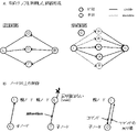
図16Aは、有向グラフを利用した経路形成を例示する図であり、図16Bは、ノード同士の関係を例示する図である。 FIG. 16A is a diagram illustrating path formation using a directed graph, and FIG. 16B is a diagram illustrating relationships between nodes.
図16Aに示すように、重要なデータは、直接知っていて信用できるノード(D)及び(E)経由で送信するようなことが可能となる。 As shown in FIG. 16A, important data can be sent via nodes (D) and (E) that are directly known and trusted.
図16Bに示すように、親ノードであるノード(L)は、委託探索を受けても探索する義務はないので、子ノードであるノード(C)は、しばらく待って何もなければ通信部21-1からネットワークNを介して委託探索を別の親ノードに送信すればよい。この場合、最低限待ち時間などのガイドラインが必要となる。
[実施例1-2]As shown in FIG. 16B, the parent node (L) is not obliged to search even if it receives the entrusted search. -1 can send a delegated search over network N to another parent node. In this case, guidelines such as minimum waiting time are required.
[Example 1-2]
実施例1-2は、実施例1でのグラフ生成と利用とを例示するものである。 Example 1-2 illustrates graph generation and use in Example 1.
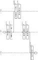
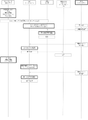
図17は、グラフ生成及び利用を例示するシーケンス図である。 FIG. 17 is a sequence diagram illustrating graph generation and utilization.
図17に示すように、ノード(A)は、ユーザIDの取得時に接続グラフに組み込まれる。ノード(A)は、通常グラフを徐々増やしていく。そして、ノード(A)は、いざ認証接続というときにグラフを利用する。
[実施例1-3]As shown in FIG. 17, node (A) is incorporated into the connection graph when the user ID is obtained. Node (A) gradually increases the normal graph. Then, node (A) uses the graph when it comes to authentication connection.
[Example 1-3]
実施例1-3は、実施例1における1親等探索リレーを例示するものである。 Example 1-3 exemplifies the first degree search relay in Example 1. FIG.
通信端末(ノード)2-mがぞれぞれの立ち位置で所定の行動をとることで全体として巨大なグラフデータベース検索が可能となる。 A huge graph database can be retrieved as a whole by the communication terminal (node) 2-m taking a predetermined action at each standing position.
図18は、1親等探索リレーを例示する図である。 FIG. 18 is a diagram exemplifying a first-degree kinship search relay.
図18に示すように、スーパーノード(S)は、特殊な通信端末(ノード)2-mであり、全員が全員に対して親子関係があるため、双方向でコマンドと戻り値とが発生する。
親ノードから子ノードに問い合わせのコマンドを送り、どこかで目的のユーザIDが見つかると、その戻り値が届いた経路を辿って最初に問い合わせたスーパーノード(S)まで戻る。
ループが発生したらその探索経路は切れる。As shown in FIG. 18, the supernode (S) is a special communication terminal (node) 2-m, and since all members have a parent-child relationship to all members, bidirectional commands and return values are generated. .
An inquiry command is sent from the parent node to the child node, and when the target user ID is found somewhere, the return value is traced back to the supernode (S) that first inquired.
If a loop occurs, the search path is broken.
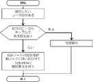
図19は、接続元ノードの行動を例示するフローチャートである。 FIG. 19 is a flowchart illustrating behavior of a connection source node.
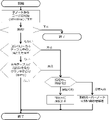
図20は、問い合わせを受けた接続親ノード(スーパーノード)の行動を示すフローチャートである。
図20に示すように、共有テーブルに当該ユーザIDを含むグラフを問合せ(query)において「はい(あり)」と判別された場合には、そもそも存在しないユーザIDの可能性もあるから実装上はここで切っている。FIG. 20 is a flow chart showing the behavior of a connected parent node (supernode) that receives an inquiry.
As shown in FIG. 20, if the graph containing the user ID in the shared table is determined to be "Yes" in the query, there is a possibility that the user ID does not exist in the first place. cutting here.
図21は、接続親ノードから問い合わせを受けたスーパーノードの行動を例示するフローチャートである。 FIG. 21 is a flow chart illustrating the behavior of a supernode queried by a connected parent node.
以上説明したように、実施例1によれば、ピア・ツウ・ピア(P2P)ネットワーク上で特定のユーザIDや属性を持つノードを、例えば、探索したいときにリクエストにグラフを含め、1親等探索をリレーすることで、高速かつ柔軟に探索することができる。 As described above, according to the first embodiment, when searching for a node having a specific user ID or attribute on a peer-to-peer (P2P) network, for example, a graph is included in a request, and a first degree search is performed. By relaying , it is possible to search quickly and flexibly.
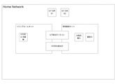
図22Aは、家庭内ネットワークの構成例を示す図であり、図22Bは、各機器のドメインを例示する図である。 FIG. 22A is a diagram showing a configuration example of a home network, and FIG. 22B is a diagram exemplifying the domain of each device.
図22Aに示す家庭内ネットワークにおいて、IоT GW、HYDRA蛍光灯、及び冷蔵庫は、ユーザIDを有するノード(リアルノード)であり、TVリモコン及びIоT蛍光灯リモコンは、バーチャルノードである。図22Bに示すように、各機器は、ドメインを持つ。 In the home network shown in FIG. 22A, the IoT GW, HYDRA fluorescent lamp, and refrigerator are nodes having user IDs (real nodes), and the TV remote controller and the IoT fluorescent lamp remote controller are virtual nodes. As shown in FIG. 22B, each device has a domain.
図23は、家庭内ネットワークの構成変更を説明するための図である。 FIG. 23 is a diagram for explaining configuration change of a home network.
図23に示すように、通常ネットワークの構成変更はハードウェア機器の組み換えを伴う工事が必要となるが、本実施例に係る家庭内ネットワークでは、各機器が論理的に抽象化されているため、ドメインネームを指定してネットワーク構成を柔軟に変更できる。 As shown in FIG. 23, changing the configuration of a network usually requires work that accompanies the modification of hardware devices. You can flexibly change the network configuration by specifying the domain name.
図24は、家庭内ネットワークの構成変更フローを例示するシーケンス図である。 FIG. 24 is a sequence diagram illustrating the configuration change flow of the home network.
図24に示す家庭内ネットワークの構成変更フローのシナリオは、家庭内ネットワークのうち玄関の鍵と寝室の照明について本日限りで、妹のスマホに入っているIoTアプリに操作権限を付与するというものである。 The scenario of the configuration change flow of the home network shown in FIG. 24 is to give the operation authority to the IoT application installed in the smartphone of the younger sister for the key of the entrance and the lighting of the bedroom in the home network only for today. be.
以上説明したように、実施例2によれば、家庭内などのIоT(Internet of Things)において、多数のデバイスをネットワーク上で管理する際に、ハードウェアによらずソフトウェアにより簡単かつ柔軟に管理することが可能となる。 As described above, according to the second embodiment, when managing a large number of devices on a network in the Internet of Things (IoT) such as at home, software can be used to easily and flexibly manage them without relying on hardware. becomes possible.
なお、本発明は、上記の実施形態に限定されず、種々の変形、応用が可能である。以下、本発明に適用可能な上記の実施形態の変形態様について、説明する。 The present invention is not limited to the above embodiments, and various modifications and applications are possible. Modifications of the above embodiments applicable to the present invention will be described below.
上記の実施形態において、制御部23-mのCPUが実行するプログラムは、予めROM等に記憶されていた。しかしながら、本発明は、これに限定されず、上述の処理を実行させるためのプログラムを、既存の汎用コンピュータに適用することで、上記の実施形態に係る通信端末(ノード)2-mとして機能させてもよい。 In the above embodiment, the program executed by the CPU of the control unit 23-m is stored in the ROM or the like in advance. However, the present invention is not limited to this, and by applying the program for executing the above-described processing to an existing general-purpose computer, the communication terminal (node) 2-m according to the above-described embodiment can be made to function. may
このようなプログラムの提供方法は任意であり、例えばコンピュータが読取可能な記録媒体(フレキシブルディスク、CD(Compact Disc)-ROM、DVD(Digital Versatile Disc)-ROM等)に格納して配布してもよいし、インターネット等のネットワーク上のストレージにプログラムを格納しておき、これをダウンロードさせることにより提供してもよい。 The method of providing such a program is arbitrary, and for example, it may be stored in a computer-readable recording medium (flexible disk, CD (Compact Disc)-ROM, DVD (Digital Versatile Disc)-ROM, etc.) and distributed. Alternatively, the program may be stored in storage on a network such as the Internet and provided by downloading it.
また、上記の処理をOSとアプリケーションプログラムとの分担、又はOSとアプリケーションプログラムとの協働によって実行する場合には、アプリケーションプログラムのみを記録媒体やストレージに格納してもよい。また、搬送波にプログラムを重畳し、ネットワークを介して配信することも可能である。例えば、ネットワーク上の掲示板(BBS:Bulletin Board System)に上記プログラムを掲示し、ネットワークを介してプログラムを配信してもよい。そして、このプログラムを起動し、OSの制御下で、他のアプリケーションプログラムと同様に実行することにより、上記の処理を実行できるように構成してもよい。 Further, when the above processing is performed by sharing the work between the OS and the application program, or by cooperation between the OS and the application program, only the application program may be stored in the recording medium or storage. It is also possible to superimpose a program on a carrier wave and distribute it via a network. For example, the program may be posted on a bulletin board (BBS: Bulletin Board System) on the network and distributed via the network. Then, the above processing may be performed by starting this program and executing it in the same manner as other application programs under the control of the OS.
なお、本発明は、本発明の広義の精神と範囲を逸脱することなく、様々な実施の形態及び変形が可能とされるものである。また、上述した実施の形態は、本発明の一実施例を説明するためのものであり、本発明の範囲を限定するものではない。 It should be noted that the present invention is capable of various embodiments and modifications without departing from the broader spirit and scope of the present invention. Moreover, the embodiment described above is for describing one example of the present invention, and does not limit the scope of the present invention.
本出願は、2020年8月21日に出願された日本国特許出願2020-140500に基づく。本明細書中に日本国特許出願2020-140500の明細書、特許請求の範囲、図面全体を参照として取り込むものとする。 This application is based on Japanese Patent Application No. 2020-140500 filed on August 21, 2020. The entire specification, claims, and drawings of Japanese Patent Application No. 2020-140500 are incorporated herein by reference.
1 通信システム
2-m 通信端末(通信ノード)
21-m 通信部
22-m 記憶部
23-m 制御部
24-m ルータ1 communication system 2-m communication terminal (communication node)
21-m Communication unit 22-m Storage unit 23-m Control unit 24-m Router
Claims (8)
子ノードに当たる前記通信ノード(2-m)を記憶する記憶部(22-m)と、
データの発信先となる前記通信ノード(2-m)である発信先ノード(2-2、B)との間の通信経路の形成が指示されたことに応答して、該発信先ノード(2-2、B)が、前記記憶部(22-m)に前記子ノードとして記憶されているか否かを判別し、前記発信先ノード(2-2、B)が子ノードとして記憶されていない場合、前記記憶部(22-m)に子ノードとして記憶されている前記通信ノード(2-1、A)に、前記発信先ノード(2-2、B)との間の通信経路の形成をさらに指示し、前記発信先ノード(2-2、B)が子ノードとして記憶されている場合、該発信先ノード(2-2、B)との間の通信経路を形成する制御部(23-m)と、
を備える通信ノード(2-m)。A communication node (2-m) that performs peer-to-peer communication,
a storage unit (22-m) for storing the communication node (2-m) corresponding to a child node;
In response to an instruction to form a communication path with a destination node (2-2, B), which is the communication node (2-m) to which data is to be sent, the destination node (2-m) -2, B) is stored as the child node in the storage unit (22-m), and if the destination node (2-2, B) is not stored as the child node , forming a communication path between the communication node (2-1, A) stored as a child node in the storage unit (22-m) and the destination node (2-2, B). If the destination node (2-2, B) is stored as a child node, a control unit (23-m )When,
A communication node (2-m) comprising:
ことを特徴とする請求項1に記載の通信ノード(2-m)。When the control unit (23-m) receives a command instructing formation of the communication path from the communication node (2-12, L) corresponding to the parent node, when the communication path is formed, the communication Sending a return value indicating that a route has been formed to the communication node (2-12, L) corresponding to the parent node;
A communication node (2-m) according to claim 1, characterized in that:
前記子ノードとして記憶されている通信ノード(2-1、A)から前記戻り値を受信したことに応答して、該戻り値を前記親ノードに当たる通信ノード(2-12、L)に送信する、
ことを特徴とする請求項2に記載の通信ノード(2-m)。When the destination node (2-2, B) is not stored as a child node, the control unit (23-m) stores the command in the storage unit (22-m) as a child node. to the communication node (2-1, A) where
In response to receiving the return value from the communication node (2-1, A) stored as the child node, the return value is transmitted to the communication node (2-12, L) corresponding to the parent node. ,
A communication node (2-m) according to claim 2, characterized in that:
前記通信ノード(2-m)は、
子ノードに当たる前記通信ノード(2-m)を記憶する記憶部(22-m)と、
データの発信先となる前記通信ノード(2-m)である発信先ノード(2-2、B)との間の通信経路の形成が指示されたことに応答して、該発信先ノード(2-2、B)が、前記記憶部(22-m)に前記子ノードとして記憶されているか否かを判別し、前記発信先ノード(2-2、B)が子ノードとして記憶されていない場合、前記記憶部(22-m)に子ノードとして記憶されている前記通信ノード(2-1、A)に、前記発信先ノード(2-2、B)との間の通信経路の形成をさらに指示し、前記発信先ノード(2-2、B)が子ノードとして記憶されている場合、該発信先ノード(2-2、B)との間の通信経路を形成する制御部(23-m)と、
を備える通信システム(1)。A communication system (1) comprising a plurality of communication nodes (2-m) that communicate in a peer-to-peer manner,
The communication node (2-m)
a storage unit (22-m) for storing the communication node (2-m) corresponding to a child node;
In response to an instruction to form a communication path with a destination node (2-2, B), which is the communication node (2-m) to which data is to be sent, the destination node (2-m) -2, B) is stored as the child node in the storage unit (22-m), and if the destination node (2-2, B) is not stored as the child node , forming a communication path between the communication node (2-1, A) stored as a child node in the storage unit (22-m) and the destination node (2-2, B); If the destination node (2-2, B) is stored as a child node, a control unit (23-m )When,
A communication system (1) comprising:
前記親ノードに当たる通信ノード(2-12、L)は、前記データの発信元となる前記通信ノード(2-m)である場合、前記戻り値を受信したことに応答して、前記形成された通信経路を介した前記発信先ノード(2-2、B)との通信を開始する、
ことを特徴とする請求項4に記載の通信システム(1)。When the control unit (23-m) receives a command instructing formation of the communication path from the communication node (2-12, L) corresponding to the parent node, when the communication path is formed, the communication sending a return value indicating that a route has been formed to the communication node (2-12, L) corresponding to the parent node;
When the communication node (2-12, L) corresponding to the parent node is the communication node (2-m) serving as the source of the data, in response to receiving the return value, the formed initiate communication with the destination node (2-2, B) via a communication path;
Communication system (1) according to claim 4, characterized in that:
前記制御部(23-m)が、データの発信先となる前記通信ノード(2-m)である発信先ノード(2-2、B)との間の通信経路の形成が指示されたことに応答して、該発信先ノード(2-2、B)が、前記記憶部(22-m)に前記子ノードとして記憶されているか否かを判別し、
前記発信先ノード(2-2、B)が子ノードとして記憶されていない場合、前記記憶部(22-m)に子ノードとして記憶されている前記通信ノード(2-1、A)に、前記発信先ノード(2-2、B)との間の通信経路の形成をさらに指示し、前記発信先ノード(2-2、B)が子ノードとして記憶されている場合、該発信先ノード(2-2、B)との間の通信経路を形成する、
ことを特徴とする通信方法。A storage unit (22-m) for storing the communication node (2-m), which is a communication node (2-m) that communicates by a peer-to-peer method and is a child node; ) and a communication method by a communication node (2-m) comprising:
that the control unit (23-m) is instructed to form a communication path with the destination node (2-2, B), which is the communication node (2-m) to which data is to be transmitted; In response, determining whether or not the destination node (2-2, B) is stored as the child node in the storage unit (22-m),
When the destination node (2-2, B) is not stored as a child node, the communication node (2-1, A) stored as a child node in the storage unit (22-m) stores the If the destination node (2-2, B) is stored as a child node, the destination node (2-2, B) is stored as a child node. -2, B) forming a communication path between
A communication method characterized by:
前記通信ノード(2-m)が、データの発信先となる前記通信ノード(2-m)である発信先ノード(2-2、B)との間の通信経路の形成が指示されたことに応答して、該発信先ノード(2-2、B)が、前記記憶部(22-m)に前記子ノードとして記憶されているか否かを判別し、
前記発信先ノード(2-2、B)が子ノードとして記憶されていない場合、前記記憶部(22-m)に子ノードとして記憶されている前記通信ノード(2-1、A)に、前記発信先ノード(2-2、B)との間の通信経路の形成をさらに指示し、前記発信先ノード(2-2、B)が子ノードとして記憶されている場合、該発信先ノード(2-2、B)との間の通信経路を形成する、
ことを特徴とする通信方法。A communication node (2-m) that performs peer-to-peer communication and has a storage unit (22-m) that stores the communication node (2-m) corresponding to a child node (2-m ) is a communication method by a communication system (1) comprising a plurality of
Formation of a communication path between the communication node (2-m) and a destination node (2-2, B), which is the communication node (2-m) to which data is to be sent, is instructed. In response, determining whether or not the destination node (2-2, B) is stored as the child node in the storage unit (22-m),
When the destination node (2-2, B) is not stored as a child node, the communication node (2-1, A) stored as a child node in the storage unit (22-m) stores the If the destination node (2-2, B) is stored as a child node, the destination node (2-2, B) is stored as a child node. -2, B) forming a communication path between
A communication method characterized by:
データの発信先となる前記通信ノード(2-m)である発信先ノード(2-2、B)との間の通信経路の形成が指示されたことに応答して、該発信先ノード(2-2、B)が、前記記憶部(22-m)に前記子ノードとして記憶されているか否かを判別する手順と、
前記発信先ノード(2-2、B)が子ノードとして記憶されていない場合、前記記憶部(22-m)に子ノードとして記憶されている前記通信ノード(2-1、A)に、前記発信先ノード(2-2、B)との間の通信経路の形成をさらに指示し、前記発信先ノード(2-2、B)が子ノードとして記憶されている場合、該発信先ノード(2-2、B)との間の通信経路を形成する手順と、
を実行させるためのプログラム。A communication node (2-m) that performs peer-to-peer communication and has a storage unit (22-m) that stores the communication node (2-m) corresponding to a child node (2-m ) computer,
In response to an instruction to form a communication path with a destination node (2-2, B), which is the communication node (2-m) to which data is to be sent, the destination node (2-m) -2, B) is stored as the child node in the storage unit (22-m);
When the destination node (2-2, B) is not stored as a child node, the communication node (2-1, A) stored as a child node in the storage unit (22-m) stores the If the destination node (2-2, B) is stored as a child node, the destination node (2-2, B) is stored as a child node. -2, B) a procedure for forming a communication path between
program to run the
Applications Claiming Priority (3)
| Application Number | Priority Date | Filing Date | Title |
|---|---|---|---|
| JP2020140500 | 2020-08-21 | ||
| JP2020140500 | 2020-08-21 | ||
| PCT/JP2021/030696 WO2022039278A1 (en) | 2020-08-21 | 2021-08-21 | Communication node, communication system, communication method, and program |
Publications (2)
| Publication Number | Publication Date |
|---|---|
| JPWO2022039278A1 JPWO2022039278A1 (en) | 2022-02-24 |
| JP7128564B2 true JP7128564B2 (en) | 2022-08-31 |
Family
ID=80323032
Family Applications (1)
| Application Number | Title | Priority Date | Filing Date |
|---|---|---|---|
| JP2022522007A Active JP7128564B2 (en) | 2020-08-21 | 2021-08-21 | Communication node, communication system, communication method, and program |
Country Status (2)
| Country | Link |
|---|---|
| JP (1) | JP7128564B2 (en) |
| WO (1) | WO2022039278A1 (en) |
Citations (1)
| Publication number | Priority date | Publication date | Assignee | Title |
|---|---|---|---|---|
| JP2012217164A (en) | 2011-03-31 | 2012-11-08 | Mitsubishi Electric Research Laboratories Inc | Method for discovering multiple routes in multi-hop networks, and nodes for searching for multiple routes |
Family Cites Families (1)
| Publication number | Priority date | Publication date | Assignee | Title |
|---|---|---|---|---|
| US20050036486A1 (en) * | 2003-08-12 | 2005-02-17 | Zafer Sahinoglu | Route discovery in ad-hoc networks with data packets |
-
2021
- 2021-08-21 JP JP2022522007A patent/JP7128564B2/en active Active
- 2021-08-21 WO PCT/JP2021/030696 patent/WO2022039278A1/en not_active Ceased
Patent Citations (1)
| Publication number | Priority date | Publication date | Assignee | Title |
|---|---|---|---|---|
| JP2012217164A (en) | 2011-03-31 | 2012-11-08 | Mitsubishi Electric Research Laboratories Inc | Method for discovering multiple routes in multi-hop networks, and nodes for searching for multiple routes |
Also Published As
| Publication number | Publication date |
|---|---|
| WO2022039278A1 (en) | 2022-02-24 |
| JPWO2022039278A1 (en) | 2022-02-24 |
Similar Documents
| Publication | Publication Date | Title |
|---|---|---|
| CN110326255B (en) | Managing messaging protocol communications | |
| TWI221979B (en) | Secured and access controlled peer-to-peer resource sharing method and apparatus | |
| Korzun et al. | Deployment of Smart Spaces in Internet of Things: Overview of the design challenges | |
| Gong | Project JXTA: A technology overview | |
| CN106209741B (en) | Virtual host, isolation method, resource access request processing method and device | |
| EP2774077B1 (en) | Method and apparatus for providing identity based encryption in distributed computations | |
| WO2013098472A1 (en) | Method and apparatus for providing social network services based on connectivity information | |
| US20220277107A1 (en) | Confidential computing workflows | |
| Al-Bahri et al. | Integrating internet of things with the digital object architecture | |
| Buthpitiya et al. | Hermes--A context-aware application development framework and toolkit for the mobile environment | |
| WO2016141783A1 (en) | Method for access control, policy acquisition, attribute acquisition and related apparatus | |
| CN117176415A (en) | Cluster access method and device, electronic equipment and storage medium | |
| CN106155566A (en) | For storing method, the Apparatus and system of data | |
| JP7128564B2 (en) | Communication node, communication system, communication method, and program | |
| CN121333777A (en) | Multi-protocol integration methods, apparatuses, devices, storage media, and software products | |
| CN113259464B (en) | Method and blockchain system for forming a blockchain subnet | |
| Mosch et al. | User-controlled resource management in federated clouds | |
| WO2018214792A1 (en) | Method and device for traffic control of user equipment | |
| CN107111635B (en) | Content delivery method | |
| Ali et al. | The quest for fully smart autonomous business networks in IoT platforms | |
| de Almeida Amazonas | Opportunities, challenges for internet of things technologies | |
| Hilia et al. | Semantic based authorization framework for multi-domain collaborative cloud environments | |
| Pandey et al. | Aglets (A java based Mobile agent) and its security issue | |
| CN111404936B (en) | File forwarding system and method | |
| Sawant et al. | Securing IoT Using MultiChain |
Legal Events
| Date | Code | Title | Description |
|---|---|---|---|
| A621 | Written request for application examination |
Free format text: JAPANESE INTERMEDIATE CODE: A621 Effective date: 20220411 |
|
| A871 | Explanation of circumstances concerning accelerated examination |
Free format text: JAPANESE INTERMEDIATE CODE: A871 Effective date: 20220411 |
|
| A521 | Request for written amendment filed |
Free format text: JAPANESE INTERMEDIATE CODE: A523 Effective date: 20220524 |
|
| TRDD | Decision of grant or rejection written | ||
| A01 | Written decision to grant a patent or to grant a registration (utility model) |
Free format text: JAPANESE INTERMEDIATE CODE: A01 Effective date: 20220809 |
|
| A61 | First payment of annual fees (during grant procedure) |
Free format text: JAPANESE INTERMEDIATE CODE: A61 Effective date: 20220812 |
|
| R150 | Certificate of patent or registration of utility model |
Ref document number: 7128564 Country of ref document: JP Free format text: JAPANESE INTERMEDIATE CODE: R150 |
|
| S111 | Request for change of ownership or part of ownership |
Free format text: JAPANESE INTERMEDIATE CODE: R313113 |
|
| R350 | Written notification of registration of transfer |
Free format text: JAPANESE INTERMEDIATE CODE: R350 |
|
| R250 | Receipt of annual fees |
Free format text: JAPANESE INTERMEDIATE CODE: R250 |