JP7128313B2 - Method and apparatus for measuring tear film thickness using optical interference - Google Patents
Method and apparatus for measuring tear film thickness using optical interference Download PDFInfo
- Publication number
- JP7128313B2 JP7128313B2 JP2021049396A JP2021049396A JP7128313B2 JP 7128313 B2 JP7128313 B2 JP 7128313B2 JP 2021049396 A JP2021049396 A JP 2021049396A JP 2021049396 A JP2021049396 A JP 2021049396A JP 7128313 B2 JP7128313 B2 JP 7128313B2
- Authority
- JP
- Japan
- Prior art keywords
- depth
- interference signal
- signal
- layer
- thickness
- Prior art date
- Legal status (The legal status is an assumption and is not a legal conclusion. Google has not performed a legal analysis and makes no representation as to the accuracy of the status listed.)
- Active
Links
Images




Classifications
-
- G—PHYSICS
- G01—MEASURING; TESTING
- G01B—MEASURING LENGTH, THICKNESS OR SIMILAR LINEAR DIMENSIONS; MEASURING ANGLES; MEASURING AREAS; MEASURING IRREGULARITIES OF SURFACES OR CONTOURS
- G01B11/00—Measuring arrangements characterised by the use of optical techniques
- G01B11/02—Measuring arrangements characterised by the use of optical techniques for measuring length, width or thickness
- G01B11/06—Measuring arrangements characterised by the use of optical techniques for measuring length, width or thickness for measuring thickness ; e.g. of sheet material
- G01B11/0616—Measuring arrangements characterised by the use of optical techniques for measuring length, width or thickness for measuring thickness ; e.g. of sheet material of coating
- G01B11/0675—Measuring arrangements characterised by the use of optical techniques for measuring length, width or thickness for measuring thickness ; e.g. of sheet material of coating using interferometry
-
- A—HUMAN NECESSITIES
- A61—MEDICAL OR VETERINARY SCIENCE; HYGIENE
- A61B—DIAGNOSIS; SURGERY; IDENTIFICATION
- A61B3/00—Apparatus for testing the eyes; Instruments for examining the eyes
- A61B3/10—Objective types, i.e. instruments for examining the eyes independent of the patients' perceptions or reactions
- A61B3/1005—Objective types, i.e. instruments for examining the eyes independent of the patients' perceptions or reactions for measuring distances inside the eye, e.g. thickness of the cornea
-
- A—HUMAN NECESSITIES
- A61—MEDICAL OR VETERINARY SCIENCE; HYGIENE
- A61B—DIAGNOSIS; SURGERY; IDENTIFICATION
- A61B3/00—Apparatus for testing the eyes; Instruments for examining the eyes
- A61B3/10—Objective types, i.e. instruments for examining the eyes independent of the patients' perceptions or reactions
- A61B3/101—Objective types, i.e. instruments for examining the eyes independent of the patients' perceptions or reactions for examining the tear film
-
- A—HUMAN NECESSITIES
- A61—MEDICAL OR VETERINARY SCIENCE; HYGIENE
- A61B—DIAGNOSIS; SURGERY; IDENTIFICATION
- A61B3/00—Apparatus for testing the eyes; Instruments for examining the eyes
- A61B3/10—Objective types, i.e. instruments for examining the eyes independent of the patients' perceptions or reactions
- A61B3/113—Objective types, i.e. instruments for examining the eyes independent of the patients' perceptions or reactions for determining or recording eye movement
-
- A—HUMAN NECESSITIES
- A61—MEDICAL OR VETERINARY SCIENCE; HYGIENE
- A61B—DIAGNOSIS; SURGERY; IDENTIFICATION
- A61B3/00—Apparatus for testing the eyes; Instruments for examining the eyes
- A61B3/10—Objective types, i.e. instruments for examining the eyes independent of the patients' perceptions or reactions
- A61B3/14—Arrangements specially adapted for eye photography
Landscapes
- Life Sciences & Earth Sciences (AREA)
- Health & Medical Sciences (AREA)
- Engineering & Computer Science (AREA)
- Physics & Mathematics (AREA)
- Molecular Biology (AREA)
- Surgery (AREA)
- Ophthalmology & Optometry (AREA)
- Biomedical Technology (AREA)
- Heart & Thoracic Surgery (AREA)
- Medical Informatics (AREA)
- Veterinary Medicine (AREA)
- Biophysics (AREA)
- Animal Behavior & Ethology (AREA)
- General Health & Medical Sciences (AREA)
- Public Health (AREA)
- Human Computer Interaction (AREA)
- General Physics & Mathematics (AREA)
- Eye Examination Apparatus (AREA)
- Length Measuring Devices By Optical Means (AREA)
- Investigating Or Analysing Materials By Optical Means (AREA)
Description
(関連出願の相互参照)
この出願は、2019年3月29日に出願された「METHOD AND APPARATUS FOR MEASURING TEAR FILM THICKNESS USING OPTICAL INTERFERENCE」と題する米国仮特許出願第62/826,495号に基づく優先権を主張するものであり、その全体を参照により本明細書に援用する。
(Cross reference to related applications)
This application claims priority to U.S. Provisional Patent Application No. 62/826,495, entitled "METHOD AND APPARATUS FOR MEASURING TEAR FILM THICKNESS USING OPTICAL INTERFERENCE," filed March 29, 2019. , which is incorporated herein by reference in its entirety.
ドライアイは、眼科医の診察における最も一般的な原因の1つになっている。ドライアイは、涙液層に関連する眼表面の多因子性疾患であり、その眼は、眼を潤滑化し栄養を与えるための十分な涙液を有しない。ドライアイを診断する1つの方法は、涙液層の厚さを測定して涙液の量を評価することである。図1に示されるように、涙液層100は、外側の油層102と、中間の水層104と、内側のムチン(粘液)層106とを含む。油層102の厚さは約50nmであり、水層104の厚さは約950nmであり、ムチン層106の厚さは約500nmである。角膜は、ムチン層の内側にて涙液層に隣接している。
Dry eye has become one of the most common causes in ophthalmologist visits. Dry eye is a multifactorial ocular surface disease associated with the tear film in which the eye does not have enough tears to lubricate and nourish the eye. One method of diagnosing dry eye is to measure tear film thickness to assess tear volume. As shown in FIG. 1 , the
現在、ドライアイの診断及び涙液層に関する他の状態の診断を客観的に支援するために涙液の層を画像化及び解析する(例えば、涙液層自体の厚さを決定する、及びその中の層の厚さを決定する)技術はほとんど存在しない。干渉技術を利用する場合、涙液の複数の層からの反射光の間の干渉は、反射率スペクトル(干渉信号)に振動の形として現れることがある。干渉信号から深さプロファイルを復元するには、干渉信号にフーリエ変換が適用される。しかしながら、油層は薄すぎるため、干渉信号から深さプロファイルを再構成するために使用されるフーリエ変換では分解できない場合がある。これは、検出された干渉信号の長さ(又は測定期間)が干渉期間に比べて比較的短い場合には、周波数領域における油層の干渉信号がDC項(直流項)に近くなりすぎてDC項やノイズと区別できないためである。このことは、インターフェログラム信号の深さプロファイルの例を表す図2に示されている。油層と水層とを合わせた厚さに対応する信号の部分は、おおよそ1μmにおけるピークとして明確に識別することができる。ただし、油層に対応する信号の部分は、深さプロファイルでは識別できない。すなわち、約50nmの油層の深さにおいて別個のピークは現れない。これにより、フーリエ変換などの解析手法を直接に使用して、結果として得た深さプロファイルから油層の厚さを決定することが困難になる。 Currently, the tear film is imaged and analyzed to objectively assist in diagnosing dry eye and other conditions related to the tear film (e.g., determining the thickness of the tear film itself and its There are few techniques for determining the thickness of inner layers. When using interference techniques, the interference between reflected light from multiple layers of tear fluid can appear in the form of oscillations in the reflectance spectrum (interference signal). A Fourier transform is applied to the interference signal to recover the depth profile from the interference signal. However, the oil layer may be too thin to be resolved by the Fourier transform used to reconstruct the depth profile from the interfering signal. This is because when the length (or measurement period) of the detected interference signal is relatively short compared to the interference period, the oil reservoir interference signal in the frequency domain becomes too close to the DC term (DC term). This is because it cannot be distinguished from noise. This is illustrated in FIG. 2, which represents an example depth profile of an interferogram signal. The portion of the signal corresponding to the combined thickness of the oil and water layers can be clearly identified as a peak at approximately 1 μm. However, the portion of the signal corresponding to the reservoir cannot be identified in the depth profile. That is, no distinct peak appears at an oil layer depth of about 50 nm. This makes it difficult to directly use analytical techniques such as the Fourier transform to determine reservoir thickness from the resulting depth profile.
したがって、油層の厚さを推定するために、様々なシミュレーション及び較正(キャリブレーション)で決定された事前計算されたテーブルとの比較やカーブフィッティングなどの技術を用いることが試みられてきた。しかし、これらの既存の方法(カーブフィッティング、事前計算されたテーブルなど)は、正確な油層の厚さを一貫して提供するために、或る制限を受ける場合がある。例えば、カーブフィッティング法は、解に収束しない場合がある(厚さ測定)。また、事前計算されたテーブルは、予め決定された測定分解能の影響を受ける場合がある。 Therefore, attempts have been made to use techniques such as curve fitting and comparison with pre-calculated tables determined by various simulations and calibrations to estimate reservoir thickness. However, these existing methods (curve fitting, pre-calculated tables, etc.) may suffer from certain limitations in order to consistently provide accurate reservoir thicknesses. For example, curve fitting methods may not converge to a solution (thickness measurements). Also, pre-computed tables may be subject to a pre-determined measurement resolution.
第1の例によれば、干渉計測法は、第1の層及び第2の層を有する対象から干渉信号を取得し、前記干渉信号は干渉撮像システムにより生成され、前記干渉信号を取得した後、前記第1の層の深さに対応する前記干渉信号の第1の干渉信号成分を求め、前記第2の層の深さに対応する前記干渉信号の第2の干渉信号成分を求め、前記第1の干渉信号成分を求めた後、前記第1の干渉信号成分に基づいて前記第1の層の厚さを求め、前記第1の層の前記厚さと前記第2の干渉信号成分とに基づいて前記第2の層の厚さを求める。 According to a first example, an interferometry method acquires an interference signal from an object having a first layer and a second layer, said interference signal is generated by an interferometric imaging system, after acquiring said interference signal , determining a first interference signal component of the interference signal corresponding to the depth of the first layer; determining a second interference signal component of the interference signal corresponding to the depth of the second layer; After determining a first interference signal component, determining a thickness of the first layer based on the first interference signal component, and combining the thickness of the first layer and the second interference signal component. Based on this, the thickness of the second layer is obtained.
上記の例の様々な実施形態は以下のいずれかの構成を有する。前記対象は第3の層を更に有し、前記第2の層は前記第1の層と前記第3の層との間に存在し、更に、前記干渉信号を取得した後、前記第3の層の深さに対応する前記干渉信号の第3の干渉信号成分を求め、前記第1、第2、及び第3の干渉信号成分を求めた後、前記第2の干渉信号成分と前記第3の干渉信号成分とに基づいて前記第3の層の厚さを求める。前記第1の干渉信号成分を求めるステップは、前記干渉信号の包絡線を計算し、前記包絡線に対してハーモニック周波数変調を所定の回数繰り返し適用することにより時間領域変調信号を生成し、前記時間領域変調信号のフーリエ変換を実行することにより周波数領域変調信号を生成し、最大強度を有する前記周波数領域変調信号の周波数を特定し、更に、前記特定された周波数を深さに変換し、前記深さは前記第1の層の前記深さに対応する、又は、前記周波数領域変調信号を深さプロファイルに変換し、更に、最大強度を有する前記深さプロファイルの深さを特定し、前記最大強度を有する前記深さは前記第1の層の前記深さに対応する。この方法は、更に、前記ハーモニック周波数変調による前記時間領域変調信号の減衰を補償する。前記第1の層の前記厚さは、前記第1の層の前記深さに等しい。この方法は、更に、前記時間領域変調信号及び/又は前記周波数領域変調信号に基づいて、前記対象の光学特性及び/又は流体特性を解析又は推定する。前記第2の干渉信号成分を求めるステップは、前記干渉信号のフーリエ変換を実行することにより周波数領域干渉信号を生成し、最大強度を有する前記周波数領域干渉信号の周波数を特定し、更に、前記特定された周波数を深さに変換し、前記深さは前記第2の層の前記深さに対応する、又は、前記周波数領域干渉信号を深さプロファイルに変換し、更に、最大強度を有する前記深さプロファイルの深さを特定し、前記最大強度を有する前記深さは前記第2の層の前記深さに対応する。前記第2の層の前記厚さは、前記第1の層の前記深さと前記第2の層の前記深さとの差に等しい。この方法は、更に、前記第1及び第2の干渉信号成分を求める前に前記干渉信号の前処理を実行する。前記前処理は、前記干渉信号のDC項の抑制を含む。前記対象は、眼の涙液層である。前記第1の層は油層であり、前記第2の層は水層又はムチン層である。前記第1の層は、前記干渉信号のフーリエ変換又はDC項が抑制された前記干渉信号のフーリエ変換により分解されないほどに薄い。 Various embodiments of the above examples have any of the following configurations. The object further comprises a third layer, the second layer being between the first layer and the third layer; After determining a third interference signal component of the interference signal corresponding to the layer depth and determining the first, second, and third interference signal components, the second interference signal component and the third interference signal component are determined. and the interference signal component of the third layer. Determining the first interference signal component includes: calculating an envelope of the interference signal; applying harmonic frequency modulation to the envelope repeatedly a predetermined number of times to generate a time domain modulated signal; generating a frequency domain modulated signal by performing a Fourier transform of a domain modulated signal; identifying a frequency of the frequency domain modulated signal having maximum intensity; transforming the identified frequency to a depth; depth corresponds to the depth of the first layer; or transforming the frequency domain modulated signal into a depth profile, further identifying a depth of the depth profile having maximum intensity, and corresponds to the depth of the first layer. The method also compensates for attenuation of the time domain modulated signal due to the harmonic frequency modulation. The thickness of the first layer is equal to the depth of the first layer. The method further analyzes or estimates optical properties and/or fluid properties of the object based on the time-domain modulated signal and/or the frequency-domain modulated signal. Determining the second interference signal component includes generating a frequency-domain interference signal by performing a Fourier transform of the interference signal, identifying a frequency of the frequency-domain interference signal having the greatest strength, converting the obtained frequencies into a depth, the depth corresponding to the depth of the second layer; A depth of the height profile is specified, said depth having said maximum intensity corresponding to said depth of said second layer. The thickness of the second layer is equal to the difference between the depth of the first layer and the depth of the second layer. The method further performs preprocessing of the interfering signal prior to determining the first and second interfering signal components. The preprocessing includes suppression of the DC term of the interfering signal. The object is the tear film of the eye. The first layer is an oil layer and the second layer is a water layer or a mucin layer. The first layer is so thin that it is not resolved by the Fourier transform of the interfering signal or the Fourier transform of the interfering signal with the DC term suppressed.
第2の例によれば、対象の厚さを求める方法は、前記対象から干渉信号を取得し、前記干渉信号の包絡線を計算し、前記包絡線に対してハーモニック周波数変調を所定の回数繰り返し適用することにより時間領域変調信号を生成し、前記変調信号のフーリエ変換を実行することにより周波数領域変調信号を生成し、最大強度を有する前記周波数領域変調信号の周波数を特定し、更に、前記特定された周波数を深さに変換し、前記深さは前記対象の前記厚さに対応する、又は、前記周波数領域変調信号を深さプロファイルに変換し、更に、最大強度を有する前記深さプロファイルの深さを特定し、前記最大強度を有する前記深さは前記対象の前記厚さに対応する。 According to a second example, a method for determining the thickness of an object comprises: obtaining an interference signal from said object; calculating an envelope of said interference signal; repeating harmonic frequency modulation on said envelope a predetermined number of times; generating a time domain modulated signal by applying; generating a frequency domain modulated signal by performing a Fourier transform of said modulated signal; identifying a frequency of said frequency domain modulated signal having maximum intensity; converting the modulated frequency to a depth, the depth corresponding to the thickness of the object; or converting the frequency domain modulated signal to a depth profile, further converting the depth profile having the maximum intensity. A depth is specified, the depth having the maximum intensity corresponding to the thickness of the object.
上記の第2の例の様々な例は以下のいずれかの構成を有する。この方法は、更に、前記ハーモニック周波数変調による前記時間領域変調信号の減衰を補償する。この方法は、更に、前記干渉信号の前記包絡線を計算する前に前記干渉信号の前処理を実行する。前記前処理は、前記干渉信号のDC項の抑制を含む。前記対象は眼の涙液層であり、前記厚さは前記涙液層の油層の厚さである。前記第1の層は、前記干渉信号のフーリエ変換又はDC項が抑制された前記干渉信号のフーリエ変換により分解されないほどに薄い。この方法は、更に、前記時間領域変調信号及び/又は前記周波数領域変調信号に基づいて、前記対象の光学特性及び/又は流体特性を解析又は推定する。 Various examples of the second example above have any of the following configurations. The method also compensates for attenuation of the time domain modulated signal due to the harmonic frequency modulation. The method further performs preprocessing of the interfering signal prior to computing the envelope of the interfering signal. The preprocessing includes suppression of the DC term of the interfering signal. The object is the tear film of the eye and the thickness is the lipid layer thickness of the tear film. The first layer is so thin that it is not resolved by the Fourier transform of the interfering signal or the Fourier transform of the interfering signal with the DC term suppressed. The method further analyzes or estimates optical properties and/or fluid properties of the object based on the time-domain modulated signal and/or the frequency-domain modulated signal.
上記を考慮し、本開示は、前述した制約を克服する涙液層厚決定に関連する。干渉計測技術を用いて(例えば、低コヒーレンストモグラフィ又は光コヒーレンストモグラフィシステムを用いて)厚さ測定を行う場合、複数の干渉信号は、測定される涙液層の各位置から検出された入射光の異なる複数の波長に対応する。これらの干渉信号は、以下に示す油層厚成分(L)、水層厚成分(A)、及びムチン層厚成分(M)に関連して定義される。






双方の厚さL+A及びL+A+Mは、OpticalInterference#3とOpticalInterference#2とのフーリエ変換を行うことによって分解及び計算することが可能である。これは、水層及びムチン層の双方の厚さが、干渉信号のそのような解析によって理解されるのに相対的に十分な厚さであることによる。しかしながら、前述したように、油層の厚さは薄すぎるため、このように分解されない。また、OpticalInterference#2は油層厚成分を含んでいるため、水層の実際の厚さを十分に決定することはできない。OpticalInterference#3も油層厚成分を含んでおり、上に示したように、OpticalInterference#3からL+A(これはOpticalInterference#2から既知である)を減算して油層厚を得ることなくムチン層厚を求めることはできない。
Both thicknesses L+A and L+A+M can be resolved and calculated by taking the Fourier transform of
本開示の方法は、油層、水層、及びムチン層のそれぞれの厚さを求めることが可能である。この方法の1つの例が図3~図5のフローチャートに示されている。簡単に言うと、OpticalInterference#2に対応する深さ及びOpticalInterference#3に対応する深さがフーリエ変換により分解され、更に並行して、ハーモニック周波数変調法により油層厚(OpticalInterference#1)が求められる。最後に、この決定された油層厚から水層厚及びムチン層厚が算出される。
The method of the present disclosure is capable of determining the thickness of each of the oil, water, and mucin layers. One example of this method is shown in the flowcharts of FIGS. 3-5. Briefly, the depth corresponding to
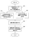
より詳細には、図3に示すように、この方法は、まず、干渉信号をロードし前処理を実行する(300)(ここで、「干渉信号」は、前処理が施された干渉信号及び前処理が施されていない干渉信号の双方を示すものとして用いられる)。図6は、例示的な干渉信号600を示している。干渉信号を取得しロードした後、干渉信号の前処理が行われる。例えば、前処理は、干渉信号のDC項を抑制するものである。干渉信号のDC項は、DCオフセットレベル(周波数ゼロ)に近い低周波信号を表す。したがって、DC項の抑制は、フィルタ(例えば、アナログ及び/又はデジタルローパスフィルタ、メディアンフィルタ、平均値フィルタ、バンドパスフィルタ、移動平均フィルタ、又は他の同様のフィルタ)を適用することによってなされる。他の実施形態において、検出された干渉信号の1次微分を取ることによってDC項を抑制することができる。もちろん、他の類似の信号処理手法を用いて、対応する周波数の除去、DCレベルの減算(サブトラクション)、又は他の同様の処理を行うことができ、また、他のノイズを除去及び/又は抑制することができる。例えば、波数の関数としての背景ノイズ、システムの較正(キャリブレーション)手順から測定される背景ノイズ、又は他の類似の背景ノイズを、ロードされた又はさもなければ取得された干渉信号600から単純に差し引くことにより、背景ノイズを除去することができる。更に言うと、背景ノイズ抑制手順の前、後、又は最中に、他の種類のノイズを抑制することができる。各タイプのノイズ抑制は、平均値フィルタ、ローパスフィルタ、バンドパスフィルタ、メディアンフィルタなどの様々なタイプのアナログ及び/又はデジタルフィルタにより実現することができ、及び/又は、ソフトウェア処理を用いて実現することができる。
More specifically, as shown in FIG. 3, the method first loads the interference signal and performs preprocessing (300) (where "interference signal" is the preprocessed interference signal and (used as an indication of both the unpreprocessed interfering signals). FIG. 6 shows an
前処理(300)に続いて、(上記したような)OpticalInterference#1に対応する深さ測定(302)と、(同じく上記したような)OpticalInterference#2及びOpticalInterference#3の深さ測定(304)とが、並行して行われる。
Following pre-processing (300), a depth measurement (302) corresponding to OpticalInterference#1 (as described above) and depth measurements (304) for
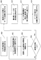
OpticalInterference#1を測定する方法の例を図4に示す。本例では、まず、干渉信号(例えば、抑制されたDC項を持つ干渉信号)の包絡線が求められる(400)。それにより得られた包絡線信号の例602を図6に示す(図6の干渉信号600の包絡線を表している)。幾つかの実施形態において、検出された干渉信号600に多項式曲線をフィッティングして干渉信号の部分OpticalInterference#1を取得することができる。その結果得られた包絡線信号を任意の信号(例えば、正弦関数又は余弦関数)としてモデル化することができる。
An example of a method for measuring
次いで、ハーモニック周波数によって包絡線信号を変調し(以下においてより詳細に説明されるハーモニック周波数変調)(402)、その結果得られた信号に変調402によって生じた減衰を補償する(404)。この変調及び補償は、反復処理として(N回)繰り返される。変調の回数(N)は、望ましい結果にしたがって予め決定されてよい。この望ましい結果は、例えば、少なくとも変調信号からDC項が識別可能となるまでであり、又は、信号対雑音比が望ましいレベル若しくは最大レベルに到達するまでである。上記の望ましい結果又は変調の具体的な回数は、ユーザによって選択されてもよいし、自動化されてもよい。幾つかの実施形態において、3回の反復が好ましい可能性がある。このハーモニック変調402、404により、後段のフーリエ変換408によって油層を分解することが可能となる。なお、幾つかの実施形態において、N回の変調が適用された後に減衰補償404を実行してもよい。
The envelope signal is then modulated by a harmonic frequency (harmonic frequency modulation, described in more detail below) (402), and the resulting signal is compensated for the attenuation caused by the modulation 402 (404). This modulation and compensation is repeated (N times) as an iterative process. The number of modulations (N) may be predetermined according to the desired result. This desired result is, for example, at least until the DC term is discernible from the modulated signal, or until the signal-to-noise ratio reaches a desired or maximum level. The specific number of desired results or modulations described above may be selected by the user or may be automated. In some embodiments, 3 iterations may be preferred. These
ハーモニック周波数変調は、リング変調の信号処理関数の特別な場合であり、一般的には音楽合成及び音響効果のために用いられる。リング変調は、2つの信号を乗算することによって実行される。ここで、2つの信号の一方は、通常は正弦波又は他の簡単な波形であり(変調信号(modulating signal))であり、他方は、変調を受ける信号(包絡線信号)である。ハーモニック周波数変調を用いることで、乗算される2つの信号は、好ましくは同じ周波数を有するが、異なる位相及び/又は異なる振幅を有していてよい(例えば、これらの信号の位相は90度ずれていてよい)。このようなハーモニック周波数変調の概念は、以下に示す例示的な等式に説明されており、これらの信号は左辺において乗算され、その結果得られる変調信号(変調された信号)が右辺に示されている。



特に、上記の例示的な等式から分かるように、変調を反復する度に、ハーモニック周波数が変調された信号の振幅が、入力された元の包絡線信号から半分に減衰される。よって、変調ごとの信号減衰の割合が大きい場合には、変調された信号に定数値を乗算することによって、変調ごとの減衰量を補償することができる。或いは、例えば、包絡線信号の2倍の振幅(又は、同様のファクタ)を有する信号を用いて変調を行うことにより、変調と同時に減衰補償を行うことが可能である。しかしながら、幾つかの実施形態においては、入力された包絡線信号の振幅が比較的大きい場合、信号の減衰量は、補償を正当化できるほど大きくなくてもよい。前述したように変調信号(modulated signal)の周波数及び振幅を制御する変調用の信号(modulating signal)に加え、変調用の信号の位相を包絡線信号に対して変化させることより変調信号の位相を制御してもよい。 In particular, as can be seen from the exemplary equations above, each iteration of modulation attenuates the amplitude of the harmonic frequency modulated signal by half from the original input envelope signal. Therefore, if the rate of signal attenuation per modulation is large, the amount of attenuation per modulation can be compensated for by multiplying the modulated signal by a constant value. Alternatively, attenuation compensation can be performed simultaneously with modulation, for example by modulating with a signal having twice the amplitude of the envelope signal (or a similar factor). However, in some embodiments, if the amplitude of the input envelope signal is relatively large, the attenuation of the signal may not be so great as to justify compensation. As described above, in addition to the modulating signal for controlling the frequency and amplitude of the modulated signal, the phase of the modulated signal is changed by changing the phase of the modulating signal with respect to the envelope signal. may be controlled.
前述したように、正弦関数や余弦関数として包絡線信号をモデル化することが可能である。包絡線信号に乗算されるハーモニック変調用信号(harmonic modulating signal)を任意の方法で形成することができる。例えば、包絡線信号と周波数が同じであるが位相が例えば90度異なるハーモニック変調用信号を生成するためにヒルベルト変換又は1次微分法を用いることができる。ハーモニック変調用信号に包絡線信号を乗算した結果が、ハーモニック周波数変調包絡線信号(harmonic frequency modulated envelope signal)である。同じく前述したように、他のハーモニック変調用信号の乗算によって、このハーモニック周波数変調包絡線信号の振幅を再び補償及び/又は変調してもよい。この補償は、結果として得られたハーモニック周波数変調包絡線信号に、ユーザにより決定されたスケール因子(scaling factor)又は所定の最適値に基づき決定されたスケール因子を乗算することによって適用されてよい。スケール因子は、例えば、望ましい信号対雑音比を維持するように選択されてよい。 As previously mentioned, it is possible to model the envelope signal as a sine or cosine function. The harmonic modulating signal that is multiplied with the envelope signal can be formed in any manner. For example, the Hilbert transform or the first derivative method can be used to generate a harmonic modulating signal that is the same in frequency as the envelope signal but out of phase, say 90 degrees. The result of multiplying the harmonic modulating signal by the envelope signal is the harmonic frequency modulated envelope signal. Again, the amplitude of this harmonic frequency modulation envelope signal may be compensated and/or modulated by multiplication with other harmonic modulating signals, also as previously described. This compensation may be applied by multiplying the resulting harmonic frequency modulated envelope signal by a scaling factor determined by the user or determined based on a predetermined optimum value. A scale factor may be selected, for example, to maintain a desired signal-to-noise ratio.
図4の参照に戻る。包絡線信号が変調され、変調に起因する減衰が補償された後、時間領域においてハーモニック周波数変調包絡線信号にフーリエ変換が実行される(408)。このフーリエ変換は、周波数領域(又は、光コヒーレンストモグラフィでは空間領域)における変調包絡線信号のパワースペクトルを生成する。次に、(例えばピーク検出法を用いて)最も高いピーク(この変調信号における最大の周波数成分)が特定され(410)、これに対応する周波数が深さに変換される(412)。この変換は、干渉信号を取得した撮像システムの初期較正に基づくものであってよい。例えば、涙液層と同等の厚さ(複数の厚さ)及び屈折率を有する涙液層を模した較正用試料を用いたシステム較正により、この較正用試料の厚さと対応する周波数とを関連付けることができる。特定された深さは、OpticalInterference#1に相当し、油層厚(L)に等しい。周波数領域における変調包絡線信号の深さプロファイル606(全ての周波数が深さに変換されている)が図6に示されている。図6の例において、入力された干渉信号は、3回変調され、更に、元の信号対雑音比を保つために各回の変調の後に一定のスケール因子により増幅された。図6から分かるように、油層深さプロファイル606において特定された最大ピークに対応する深さは、48.525nmである。或いは、周波数領域の変調信号は、まず深さプロファイル606に変換されてよく、更に、この周波数領域の変調信号ではなく深さプロファイルから最大ピークを特定してもよい。そして、特定された深さを、後の解析のために保存することができる(414)。
Returning to the reference to FIG. After the envelope signal is modulated and the attenuation due to the modulation is compensated, a Fourier transform is performed on the harmonic frequency modulated envelope signal in the time domain (408). This Fourier transform produces the power spectrum of the modulated envelope signal in the frequency domain (or spatial domain for optical coherence tomography). The highest peak (the highest frequency component in the modulated signal) is then identified (410) (eg, using a peak detection method) and its corresponding frequency is converted to depth (412). This transformation may be based on an initial calibration of the imaging system that acquired the interference signal. For example, by calibrating the system using a calibration sample that mimics the tear film with a thickness (thicknesses) and refractive index comparable to the tear film, the thickness of this calibration sample is related to the corresponding frequency. be able to. The specified depth corresponds to
図3の参照に戻る。OpticalInterference#1及び油層厚と並行して、OpticalInterference#2(L+A)に対応する深さ及びOpticalInterference#3(L+A+M)に対応する深さが特定される(304)。OpticalInterference#2及びOpticalInterference#3を求める処理は、ハーモニック周波数変調を除いて、前述したOpticalInterference#1を求める処理と同様である。そのような処理の例を図5に示す。同処理において、(例えば、抑制されたDC項を有する)干渉信号に対してフーリエ変換が直接に実行される(500)。更に、(例えば、ピーク検出法によって)2つの最大ピークを有する周波数(干渉信号における最大周波数成分)が特定され(502)、これらの周波数が(例えば、前述した初期較正又は同様の手法に基づいて)深さに変換される(504)。上記と同様に、他の実施形態は、最大ピークを特定する前に、信号全体を深さに変換してもよい。最も大きい成分の周波数での深さは、OpticalInterference#2の深さ(油層と水層とを合わせた深さ、水層とムチン層との境界の深さ)に相当し、2番目に大きい成分の周波数での深さは、OpticalInterference#3の深さ(油層と水層とムチン層とを合わせた深さ)に相当する。なお、幾つかの例において、一般に、光反射の低さのために、ムチン層からの第2番目のピークが見つからないことがある。前述したハーモニック周波数変調により測定された深さプロファイル604が図6に示されており、OpticalInterference#2に対応する最大ピークは990.2nmに位置している。しかしながら、ムチン層の深さについては、前述した(そして以下においても説明するように)深さと干渉信号との関係を考慮することにより水層の深さと油層の深さとに基づいて求めてもよい。そして、これらの深さは、後の解析のために保存される(506)。
Returning to reference to FIG. In parallel with
図3の参照に戻る。(例えば、図4及び図5の方法にて保存されたように)全てが既知のOpticalInterference#1に対応する深さ、OpticalInterference#2に対応する深さ、及びOpticalInterference#3に対応する深さを用いて、各層の個々の深さを求めることができる。各光干渉についての上記等式に基づくと次のようになる。
油層厚(L)=OpticalInterference#1(図4の処理にて保存されたもの)
水層厚(A)=OpticalInterference#2(図4の処理にて保存されたもの)-OpticalInterference#1(図4の処理にて保存されたもの)
ムチン層厚(M)=OpticalInterference#3(図5の処理にて保存されたもの)-OpticalInterference#2(図4の処理にて保存されたもの)
Returning to reference to FIG. The depth corresponding to
Oil layer thickness (L) = OpticalInterference#1 (those saved by processing in Figure 4)
Aqueous layer thickness (A) = OpticalInterference#2 (stored in the process of Figure 4) - OpticalInterference#1 (stored in the process of Figure 4)
Mucin layer thickness (M) = OpticalInterference#3 (preserved in the process of Figure 5) - OpticalInterference#2 (preserved in the process of Figure 4)
換言すると、OpticalInterference#2及びOpticalInterference#3から求められた油層+水層+ムチン層の厚さ及び/又は油層+水層の厚さから油層厚を減算することによって、水層厚とムチン層厚とを算出することができる。図6の例を用いると、油層厚(L)(OpticalInterference#1)は48.525nmであり、油層の深さプロファイル606における最大ピークの深さである。よって、水層厚(A)は、水層+油層の厚さ(OpticalInterference#2)に対応する深さと、OpticalInterference#1との差分である。すなわち、水層厚は、990.2nm-48.525nm=941.675nmに等しい。本例では、入力された干渉信号は、3回変調され、更に、元の信号対雑音比を保つために各回の変調の後に一定のスケール因子により増幅された。
In other words, by subtracting the oil layer thickness from the thickness of the oil layer + water layer + mucin layer and/or the thickness of the oil layer + water layer obtained from
図4に対応する上記の処理と図5に対応する上記の処理とは並行して行われるように説明したが、これらを同時に実行する必要はない。むしろ、OpticalInterference#1(油層厚)の決定は、簡便に、OpticalInterference#2及びOpticalInterference#3(油層と水層とを合わせた厚さ、及び、油層と水層とムチン層とを合わせた厚さ)とは別に行われる。これにより、図5の処理の前又は後に図4の処理を行うことができるが、干渉信号のロード/取得及び処理の後に双方の処理が完了され、また、従来技術が最終的に水層厚とムチン層厚とを求める。
Although the above processing corresponding to FIG. 4 and the above processing corresponding to FIG. 5 have been described as being performed in parallel, they need not be performed at the same time. Rather, the determination of OpticalInterference#1 (oil layer thickness) is conveniently based on
最後に、各層厚が算出された後、後の使用のために最終結果を表示及び/又は保存することができ、また、干渉信号から得た付加的情報を解析、保存、表示、又は同様のために抽出することができる(308)。そのような付加的情報は、光干渉信号の光学位相を含んでいてよく、又は、粘度、流速、並びに/又は媒質の変形、振動及び/若しくは変化などの流体特性を含んでいてもよい。 Finally, after each layer thickness is calculated, the final results can be displayed and/or stored for later use, and additional information obtained from the interference signal can be analyzed, stored, displayed, or otherwise processed. can be extracted (308) for Such additional information may include the optical phase of the optical interference signal, or may include fluid properties such as viscosity, flow velocity, and/or deformation, vibration and/or change of the medium.
より具体的には、ハーモニック変調信号(例えば、油層厚を求める場合には図4の方法にしたがい導かれたようなもの)は、元の干渉信号の光学位相(θ)の情報をまだ持っていてよい。この位相情報は、涙液層の光学特性及び流体特性(例えば、粘度、粒子の動き、温度、屈折率、及び同様の特性)を推定及び解析するために有用である。変調された干渉信号のフーリエ変換を行うことによって光学位相情報を抽出することが可能である。一般に、光学位相の知識(情報)。 More specifically, the harmonically modulated signal (such as that derived according to the method of FIG. 4 when determining oil layer thickness) still has information of the optical phase (θ) of the original interference signal. you can This phase information is useful for estimating and analyzing tear film optical and fluid properties (eg, viscosity, particle motion, temperature, refractive index, and similar properties). Optical phase information can be extracted by taking a Fourier transform of the modulated interference signal. In general, the knowledge (information) of the optical phase.
一般に、光干渉信号I(x、ν、t)は次式のように表される。


しかしながら、連続する2つのBスキャンの間の時間間隔Δtの間における瞬間的な距離Δd(x、z)の散乱の移動(translation)により、Φ(x、z、t)=4πnΔd(x、z、t)/λ0で与えられる反射光の光学位相の測定値の局所的変化が引き起こされる。ここで、λ0は光源の中心波長であり、nはサンプルの屈折率である。測定されるΦ(x、z、t)は、(-π、π)ラジアンの範囲にラップ(wrap)される。よって、位相アンラッピング法(phase-unwrapping)法を用いて実際の光学位相の変化を求めることができ、また、光線方向における局所化された涙液層速度を
ν(x、z、t)=ΔΦ(x、z、t)λ0(4πnΔt)-1から導くことができる。そして、深さ分解された瞬間的な変位及び速度を用いて、ひずみ速度や粘度といったサンプルの特性を算出することができる。
However, due to the scatter translation of the instantaneous distance Δd(x,z) during the time interval Δt between two consecutive B-scans, Φ(x,z,t)=4πnΔd(x,z , t)/λ 0 causes a local change in the measured optical phase of the reflected light. where λ 0 is the center wavelength of the light source and n is the refractive index of the sample. The measured Φ(x,z,t) is wrapped to a range of (−π,π) radians. Thus, a phase-unwrapping method can be used to determine the actual optical phase change, and the localized tear film velocity in the ray direction can be defined as ν(x, z, t)= It can be derived from ΔΦ(x, z, t)λ 0 (4πnΔt) −1 . The instantaneous depth-resolved displacements and velocities can then be used to calculate sample properties such as strain rate and viscosity.
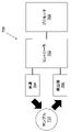
更に、図7に示すハーモニック周波数変調システム(HFMS)700などのシステムにおいて上記の方法を実行してもよい。本例において、コントローラ702は、光源704及び検出器706を含む近くのデバイスを制御するように構成されている。加えて、コントローラ702はプロセッサ708と通信を行う。プロセッサ708は、ハーモニック周波数変調法を用いて求められたような、涙液層厚測定などで求められた特性の表示を制御することによって、及び、適当な信号処理、演算などを実行することによって、前述した方法を実行する。コントローラ702及びプロセッサ708はともに、コンピュータ(例えば、メモリ、記憶装置(例えば、フラッシュ記憶装置、ハードディスクドライブ)、入力/出力ヒューマンインターフェイス装置(例えば、キーボード、マウス、タッチスクリーン、ディスプレイ)、などを更に含む)を構成する。
Additionally, the above method may be implemented in a system such as the harmonic frequency modulation system (HFMS) 700 shown in FIG. In this example,
例えば、光源704及び検出器706を用いた低コヒーレンス干渉法(LCI)、光コヒーレンストモグラフィ(OCT)、又は同様の手法など、サンプル710(例えば、被検眼)の干渉計測イメージング技術/システムを用いて、本明細書で説明した干渉信号を取得してもよい。幾つかの実施形態において、検出器706は、分光器、ハイパースペクトル検出器/撮像装置、又は同様のデバイスであってよい。涙液層厚測定の場合、例えば、眼科スクリーニングにおいて被検眼にLCI又はOCTスキャンを行うことによって干渉信号を取得することができる。 Using an interferometric imaging technique/system of the sample 710 (e.g., subject eye), such as, for example, low coherence interferometry (LCI) using light source 704 and detector 706, optical coherence tomography (OCT), or similar techniques. to obtain the interfering signals described herein. In some embodiments, detector 706 may be a spectrometer, hyperspectral detector/imager, or similar device. In the case of tear film thickness measurements, for example, the interferometric signal can be obtained by performing an LCI or OCT scan on the subject eye during ophthalmic screening.
プロセッサ708及びコントローラ702は、LCIシステム又はOCTシステムと統合されていてもよいし(例えば、共通のコンピュータ及び周辺機器を共有している)、或いは、別々であってもよい(例えば、互いに離れて配置されている)。このような統合にかかわらず、説明された方法は、干渉計測イメージングスキャンの実行の直後に(又は、これに次いで)実行されてもよく、或いは、実質的に後の時間に実行されてもよい。また、説明された方法は、臨床医の診療室にて行われてもよいし(例えば、臨床医がOCTスキャンを行う)、又は、集中化された場所にて行われてもよい。
Processor 708 and
また、様々な信号処理は、ハードウェア(例えば、ディスクリート回路)として実装されてもよいし、又は、プロセッサ又はコントローラにプログラムされたソフトウェアとして実装されてもよい。例えば、時計回り又は反時計回りに向き付けられた複数のダイオードを有するブリッジ整流器としてハーモニック変調回路を具現化してもよい。 Also, various signal processing may be implemented as hardware (eg, discrete circuits) or as software programmed into a processor or controller. For example, the harmonic modulation circuit may be embodied as a bridge rectifier with multiple diodes oriented clockwise or counterclockwise.
以上を考慮すると、本明細書で説明された方法及びシステムは、現在の涙液層イメージング技術及び涙液層解析技術を、少なくとも以下の点において向上させる;1)各涙液層についての厚さ測定を提供できること;2)非常に薄い層を測定できること(光源の中心波長よりずっと薄い層でもよい);3)実施や実装が容易であること;4)層厚の測定だけでなく、光干渉信号の光学位相も測定できること;5)粘度、流速、媒質の変形/振動/変化といった流体特性及び光学特性を評価できること。 In view of the above, the methods and systems described herein improve current tear film imaging and analysis techniques in at least the following ways: 1) thickness for each tear film; 2) the ability to measure very thin layers (even layers much thinner than the center wavelength of the light source); 3) the ease of implementation and implementation; 4) the optical interference as well as the measurement of layer thickness. It should also be able to measure the optical phase of the signal; 5) it should be able to evaluate fluid and optical properties such as viscosity, flow velocity, deformation/vibration/change of medium.
上記の説明は涙液層厚測定に関するものであるが、本開示は任意の層厚の測定に関連するものであり、特に、正確且つ高い信頼性で分解するには薄すぎる厚さの層を含む多層構造を対象とする。また、そのような多層構造は、3層に限定されず、2層だけでもよいし、他の実施形態では3層を超えてもよい。 Although the above description relates to tear film thickness measurement, the present disclosure relates to measurement of any layer thickness, and in particular to measuring a layer that is too thin to be resolved accurately and reliably. It is intended for multi-layer structures including Also, such multi-layer structures are not limited to three layers, but may have only two layers, or more than three layers in other embodiments.
Claims (15)
前記対象から干渉信号を取得し、
前記干渉信号の包絡線を計算し、
前記包絡線に対してハーモニック周波数変調を所定の回数繰り返し適用することにより時間領域変調信号を生成し、
前記変調信号のフーリエ変換を実行することにより周波数領域変調信号を生成し、
最大強度を有する前記周波数領域変調信号の周波数を特定し、
前記特定された周波数を深さに変換し、
前記深さは前記対象の前記厚さに対応する、
装置。 An apparatus for determining the thickness of an object, comprising:
obtaining an interfering signal from the target;
calculating an envelope of the interfering signal;
generating a time domain modulated signal by repeatedly applying harmonic frequency modulation to the envelope a predetermined number of times;
generating a frequency domain modulated signal by performing a Fourier transform of the modulated signal;
identifying the frequency of the frequency domain modulated signal having the maximum intensity;
converting the identified frequency to depth;
said depth corresponds to said thickness of said object;
Device.
前記対象から干渉信号を取得し、
前記干渉信号の包絡線を計算し、
前記包絡線に対してハーモニック周波数変調を所定の回数繰り返し適用することにより時間領域変調信号を生成し、
前記変調信号のフーリエ変換を実行することにより周波数領域変調信号を生成し、
前記周波数領域変調信号を深さプロファイルに変換し、
最大強度を有する前記深さプロファイルの深さを特定し、
前記最大強度を有する前記深さは前記対象の前記厚さに対応する、
装置。 An apparatus for determining the thickness of an object, comprising:
obtaining an interfering signal from the target;
calculating an envelope of the interfering signal;
generating a time domain modulated signal by repeatedly applying harmonic frequency modulation to the envelope a predetermined number of times;
generating a frequency domain modulated signal by performing a Fourier transform of the modulated signal;
converting the frequency domain modulated signal into a depth profile;
identifying the depth of the depth profile having maximum intensity;
said depth having said maximum intensity corresponds to said thickness of said object;
Device.
更に、
前記多層構造から干渉信号を取得し、前記対象の前記干渉信号は第1の干渉信号成分に対応し、前記第1の干渉信号成分は前記第1の層の深さに対応し、
前記多層構造からの前記干渉信号の第2の干渉信号成分を求め、前記第2の干渉信号成分は第2の層の深さに対応し、
前記第2の干渉信号成分と前記対象の前記特定された厚さとに基づいて前記第2の層の厚さを求める、
請求項1又は2の装置。 said target is a first layer of a multi-layer structure;
Furthermore,
obtaining an interference signal from the multilayer structure, the interference signal of the object corresponding to a first interference signal component, the first interference signal component corresponding to a depth of the first layer;
determining a second interference signal component of the interference signal from the multilayer structure, the second interference signal component corresponding to a depth of a second layer;
determining a thickness of the second layer based on the second interference signal component and the determined thickness of the target;
3. Apparatus according to claim 1 or 2.
更に、
前記多層構造からの前記干渉信号の第3の干渉信号成分を求め、前記第3の干渉信号成分は第3の層の深さに対応し、
前記第2の干渉信号成分と前記第3の干渉信号成分とに基づいて前記第3の層の厚さを求める、
請求項3の装置。 said multilayer structure further comprising a third layer, said second layer being between said first layer and said third layer;
Furthermore,
determining a third interference signal component of the interference signal from the multilayer structure, the third interference signal component corresponding to a third layer depth;
determining a thickness of the third layer based on the second interference signal component and the third interference signal component;
4. The apparatus of claim 3.
前記多層構造からの前記干渉信号のフーリエ変換を実行することにより周波数領域干渉信号を生成し、
最大強度を有する前記周波数領域干渉信号の周波数を特定し、
前記特定された周波数を深さに変換し、
前記変換により取得された前記深さは前記第2の層の前記深さに対応する、
請求項3又は4の装置。 Determining the second interference signal component comprises:
generating a frequency domain interference signal by performing a Fourier transform of the interference signal from the multilayer structure;
identifying the frequency of the frequency-domain interference signal that has the greatest intensity;
converting the identified frequency to depth;
the depth obtained by the transformation corresponds to the depth of the second layer;
5. Apparatus according to claim 3 or 4.
前記多層構造からの前記干渉信号のフーリエ変換を実行することにより周波数領域干渉信号を生成し、
前記周波数領域干渉信号を深さプロファイルに変換し、
最大強度を有する前記深さプロファイルの深さを特定し、
前記最大強度を有する前記深さは前記第2の層の前記深さに対応する、
請求項3又は4の装置。 Determining the second interference signal component comprises:
generating a frequency domain interference signal by performing a Fourier transform of the interference signal from the multilayer structure;
transforming the frequency domain interference signal into a depth profile;
identifying the depth of the depth profile having maximum intensity;
said depth having said maximum intensity corresponds to said depth of said second layer;
5. Apparatus according to claim 3 or 4.
請求項3~6のいずれかの装置。 wherein said multilayered structure is the tear film of the eye;
Apparatus according to any of claims 3-6.
請求項1~7のいずれかの装置。 wherein the target is the lipid layer of the tear film of the eye;
Apparatus according to any of claims 1-7.
請求項1~8のいずれかの装置。 further performing preprocessing of the interfering signal from the target prior to calculating the envelope of the interfering signal;
Apparatus according to any of claims 1-8.
請求項3~7のいずれかの装置。 further performing preprocessing of the interference signal from the multilayer structure prior to calculating the envelope of the interference signal;
Apparatus according to any of claims 3-7.
請求項9又は10の装置。 wherein the preprocessing includes suppression of the interfering signal;
11. Apparatus according to claim 9 or 10.
請求項1~11のいずれかの装置。 the object is so thin that it cannot be resolved by a Fourier transform of the interfering signal or a Fourier transform of the interfering signal with the DC term suppressed;
Apparatus according to any of claims 1-11.
請求項1~12のいずれかの装置。 further analyzing or estimating optical properties and/or fluid properties of the object based on the time-domain modulated signal and/or the frequency-domain modulated signal;
Apparatus according to any of claims 1-12.
請求項1~13のいずれかの装置。 the interference signal from the object is obtained by a spectroscope;
Apparatus according to any of claims 1-13.
請求項3~7、及び10のいずれかの装置。 the interference signal from the multilayer structure is obtained by a spectroscope;
Apparatus according to any of claims 3-7 and 10.
Priority Applications (1)
| Application Number | Priority Date | Filing Date | Title |
|---|---|---|---|
| JP2022066659A JP7309007B2 (en) | 2019-03-29 | 2022-04-14 | Method and apparatus for measuring tear film thickness using optical interference |
Applications Claiming Priority (5)
| Application Number | Priority Date | Filing Date | Title |
|---|---|---|---|
| US201962826495P | 2019-03-29 | 2019-03-29 | |
| US62/826,495 | 2019-03-29 | ||
| US16/829,673 US11614321B2 (en) | 2019-03-29 | 2020-03-25 | Method and apparatus for measuring tear film thickness using optical interference |
| US16/829,673 | 2020-03-25 | ||
| JP2020058105A JP6860723B2 (en) | 2019-03-29 | 2020-03-27 | Methods and devices for measuring tear film thickness using light interference |
Related Parent Applications (1)
| Application Number | Title | Priority Date | Filing Date |
|---|---|---|---|
| JP2020058105A Division JP6860723B2 (en) | 2019-03-29 | 2020-03-27 | Methods and devices for measuring tear film thickness using light interference |
Related Child Applications (1)
| Application Number | Title | Priority Date | Filing Date |
|---|---|---|---|
| JP2022066659A Division JP7309007B2 (en) | 2019-03-29 | 2022-04-14 | Method and apparatus for measuring tear film thickness using optical interference |
Publications (2)
| Publication Number | Publication Date |
|---|---|
| JP2021094432A JP2021094432A (en) | 2021-06-24 |
| JP7128313B2 true JP7128313B2 (en) | 2022-08-30 |
Family
ID=70058174
Family Applications (5)
| Application Number | Title | Priority Date | Filing Date |
|---|---|---|---|
| JP2020058105A Active JP6860723B2 (en) | 2019-03-29 | 2020-03-27 | Methods and devices for measuring tear film thickness using light interference |
| JP2021049397A Active JP7043653B2 (en) | 2019-03-29 | 2021-03-24 | Methods and devices for measuring tear film thickness using light interference |
| JP2021049396A Active JP7128313B2 (en) | 2019-03-29 | 2021-03-24 | Method and apparatus for measuring tear film thickness using optical interference |
| JP2021049398A Active JP7043654B2 (en) | 2019-03-29 | 2021-03-24 | Methods and devices for measuring tear film thickness using light interference |
| JP2022066659A Active JP7309007B2 (en) | 2019-03-29 | 2022-04-14 | Method and apparatus for measuring tear film thickness using optical interference |
Family Applications Before (2)
| Application Number | Title | Priority Date | Filing Date |
|---|---|---|---|
| JP2020058105A Active JP6860723B2 (en) | 2019-03-29 | 2020-03-27 | Methods and devices for measuring tear film thickness using light interference |
| JP2021049397A Active JP7043653B2 (en) | 2019-03-29 | 2021-03-24 | Methods and devices for measuring tear film thickness using light interference |
Family Applications After (2)
| Application Number | Title | Priority Date | Filing Date |
|---|---|---|---|
| JP2021049398A Active JP7043654B2 (en) | 2019-03-29 | 2021-03-24 | Methods and devices for measuring tear film thickness using light interference |
| JP2022066659A Active JP7309007B2 (en) | 2019-03-29 | 2022-04-14 | Method and apparatus for measuring tear film thickness using optical interference |
Country Status (4)
| Country | Link |
|---|---|
| US (1) | US11614321B2 (en) |
| EP (1) | EP3714769B1 (en) |
| JP (5) | JP6860723B2 (en) |
| DE (1) | DE20166633T1 (en) |
Families Citing this family (4)
| Publication number | Priority date | Publication date | Assignee | Title |
|---|---|---|---|---|
| US11614321B2 (en) * | 2019-03-29 | 2023-03-28 | Topcon Corporation | Method and apparatus for measuring tear film thickness using optical interference |
| JP2024032466A (en) * | 2022-08-29 | 2024-03-12 | 株式会社Soken | oil thickness measuring device |
| CN119665837B (en) * | 2024-12-16 | 2026-01-02 | 江苏大学 | A method for detecting thin film thickness using terahertz technology |
| CN120113994B (en) * | 2025-04-11 | 2025-12-12 | 安徽大学 | Multi-parameter eye axis measurement and data processing system based on self-mixing vernier effect |
Citations (5)
| Publication number | Priority date | Publication date | Assignee | Title |
|---|---|---|---|---|
| JP2008545957A (en) | 2005-05-19 | 2008-12-18 | ザイゴ コーポレーション | Method and system for analyzing low coherence interferometer signals for information about thin film structures |
| US20160338585A1 (en) | 2014-03-06 | 2016-11-24 | ADOM, Advanced Optical Technologies Ltd | System and Method for Performing Tear Film Structure Measurement and Evaporation Rate Measurements |
| JP2018047084A (en) | 2016-09-23 | 2018-03-29 | 株式会社トプコン | Ophthalmologic examination apparatus |
| JP2018084434A (en) | 2016-11-21 | 2018-05-31 | 株式会社東京精密 | Measuring apparatus and measuring method |
| JP2019191087A (en) | 2018-04-27 | 2019-10-31 | 株式会社日立ハイテクサイエンス | Interference signal phase correction method |
Family Cites Families (17)
| Publication number | Priority date | Publication date | Assignee | Title |
|---|---|---|---|---|
| DE50015215D1 (en) * | 1999-09-10 | 2008-07-31 | Haag Ag Streit | DEVICE FOR PHOTOABLATION OF THE CORNEA WITH A LASER BEAM |
| WO2001038820A1 (en) * | 1999-11-24 | 2001-05-31 | Haag-Streit Ag | Method and device for measuring the optical properties of at least two regions located at a distance from one another in a transparent and/or diffuse object |
| JP4846938B2 (en) * | 2001-08-14 | 2011-12-28 | 株式会社トプコン | Eye characteristics measuring device |
| US20070213792A1 (en) * | 2002-10-07 | 2007-09-13 | Palomar Medical Technologies, Inc. | Treatment Of Tissue Volume With Radiant Energy |
| US7324214B2 (en) | 2003-03-06 | 2008-01-29 | Zygo Corporation | Interferometer and method for measuring characteristics of optically unresolved surface features |
| JP2006250826A (en) * | 2005-03-11 | 2006-09-21 | Yamagata Prefecture | Measuring element, processing apparatus and measuring method, refractive index measuring element |
| DE102006016131A1 (en) * | 2005-09-22 | 2007-03-29 | Robert Bosch Gmbh | Interferometric measuring device |
| WO2008137863A2 (en) * | 2007-05-04 | 2008-11-13 | Advanced Medical Optics, Inc. | Methods and devices for measuring tear film and diagnosing tear disorders |
| JP5938926B2 (en) * | 2012-01-31 | 2016-06-22 | 株式会社ニデック | Optical tomography apparatus and noise removal method |
| US9795290B2 (en) | 2013-11-15 | 2017-10-24 | Tearscience, Inc. | Ocular tear film peak detection and stabilization detection systems and methods for determining tear film layer characteristics |
| US9615735B2 (en) | 2014-01-31 | 2017-04-11 | University Of Rochester | Measurement of the lipid and aqueous layers of a tear film |
| US10054419B2 (en) | 2014-05-01 | 2018-08-21 | Adom, Advanced Optical Technologies Ltd. | Method for analyzing an object using a combination of long and short coherence interferometry |
| ES2767054T3 (en) * | 2015-04-15 | 2020-06-16 | Alcon Inc | An apparatus for modeling eye structures |
| JP7068869B2 (en) * | 2017-03-14 | 2022-05-17 | 株式会社トプコン | Tear layer thickness measuring device and method |
| JP2019055106A (en) * | 2017-09-22 | 2019-04-11 | 株式会社トプコン | Ophthalmologic examination apparatus |
| JP2019154764A (en) * | 2018-03-13 | 2019-09-19 | 株式会社トプコン | Tear film thickness measurement apparatus and method |
| US11614321B2 (en) * | 2019-03-29 | 2023-03-28 | Topcon Corporation | Method and apparatus for measuring tear film thickness using optical interference |
-
2020
- 2020-03-25 US US16/829,673 patent/US11614321B2/en active Active
- 2020-03-27 JP JP2020058105A patent/JP6860723B2/en active Active
- 2020-03-30 EP EP20166633.6A patent/EP3714769B1/en active Active
- 2020-03-30 DE DE20166633.6T patent/DE20166633T1/en active Pending
-
2021
- 2021-03-24 JP JP2021049397A patent/JP7043653B2/en active Active
- 2021-03-24 JP JP2021049396A patent/JP7128313B2/en active Active
- 2021-03-24 JP JP2021049398A patent/JP7043654B2/en active Active
-
2022
- 2022-04-14 JP JP2022066659A patent/JP7309007B2/en active Active
Patent Citations (5)
| Publication number | Priority date | Publication date | Assignee | Title |
|---|---|---|---|---|
| JP2008545957A (en) | 2005-05-19 | 2008-12-18 | ザイゴ コーポレーション | Method and system for analyzing low coherence interferometer signals for information about thin film structures |
| US20160338585A1 (en) | 2014-03-06 | 2016-11-24 | ADOM, Advanced Optical Technologies Ltd | System and Method for Performing Tear Film Structure Measurement and Evaporation Rate Measurements |
| JP2018047084A (en) | 2016-09-23 | 2018-03-29 | 株式会社トプコン | Ophthalmologic examination apparatus |
| JP2018084434A (en) | 2016-11-21 | 2018-05-31 | 株式会社東京精密 | Measuring apparatus and measuring method |
| JP2019191087A (en) | 2018-04-27 | 2019-10-31 | 株式会社日立ハイテクサイエンス | Interference signal phase correction method |
Also Published As
| Publication number | Publication date |
|---|---|
| JP2021094433A (en) | 2021-06-24 |
| EP3714769A1 (en) | 2020-09-30 |
| JP2022097518A (en) | 2022-06-30 |
| JP6860723B2 (en) | 2021-04-21 |
| JP7309007B2 (en) | 2023-07-14 |
| US11614321B2 (en) | 2023-03-28 |
| JP7043653B2 (en) | 2022-03-29 |
| JP2021094432A (en) | 2021-06-24 |
| JP2020163147A (en) | 2020-10-08 |
| EP3714769B1 (en) | 2023-09-20 |
| JP2021094434A (en) | 2021-06-24 |
| US20200309510A1 (en) | 2020-10-01 |
| JP7043654B2 (en) | 2022-03-29 |
| DE20166633T1 (en) | 2020-12-31 |
Similar Documents
| Publication | Publication Date | Title |
|---|---|---|
| JP7309007B2 (en) | Method and apparatus for measuring tear film thickness using optical interference | |
| KR102225808B1 (en) | Skin diagnosis device, skin condition output method, program, and recording medium | |
| Zvietcovich et al. | Comparative study of shear wave-based elastography techniques in optical coherence tomography | |
| EP1869398B1 (en) | Apparatus and method for frequency-domain optical coherence tomography | |
| US20200265580A1 (en) | Systems and methods for reducing artifacts in oct angiography images | |
| Horstmann et al. | Full-field speckle interferometry for non-contact photoacoustic tomography | |
| EP2784438B1 (en) | Method for generating two-dimensional images from three-dimensional optical coherence tomography interferogram data | |
| US10203195B2 (en) | Noise reduction techniques, fractional bi-spectrum and fractional cross-correlation, and applications | |
| Buj et al. | Noncontact holographic detection for photoacoustic tomography | |
| Ksenofontov et al. | Numerical method for axial motion artifact correction in retinal spectral-domain optical coherence tomography | |
| JP7318046B2 (en) | 2D multilayer thickness measurement | |
| Matkivsky et al. | Medium chromatic dispersion calculation and correction in spectral-domain optical coherence tomography | |
| JP6242644B2 (en) | Image measuring method and image measuring apparatus | |
| JP2018115939A (en) | Apparatus and method for visualizing fault content | |
| Uchida et al. | Non-uniform non-harmonic analysis method development and verification of applicability to swept source optical coherence tomography | |
| Chan et al. | Maximum likelihood Doppler frequency estimation under decorrelation noise for quantifying flow in optical coherence tomography | |
| Kumar et al. | Enhanced A-scan spatial resolution in spectral domain OCT exploiting the Wigner-Ville technique | |
| Gelikonov et al. | Numerical method for axial motion correction in optical coherence tomography | |
| Choma et al. | Wavelet and model-based spectral analysis of color doppler optical coherence tomography | |
| Song et al. | Shear Wave Elastography Based on Optical Coherence Tomography | |
| Li | Development of a simple full field optical coherence tomography system and its applications | |
| Rosa | Numerical study on spectral domain optical coherence tomography spectral calibration and re-sampling importance | |
| Malektaji | Monte Carlo simulation of optical coherence tomography of media with arbitrary spatial distributions | |
| Grimwood | Imaging elastographic contrast in optical coherence tomography for applications in dermatology and oncology | |
| Donges et al. | Optical Coherence Tomography: OCT |
Legal Events
| Date | Code | Title | Description |
|---|---|---|---|
| A621 | Written request for application examination |
Free format text: JAPANESE INTERMEDIATE CODE: A621 Effective date: 20210401 |
|
| A977 | Report on retrieval |
Free format text: JAPANESE INTERMEDIATE CODE: A971007 Effective date: 20220125 |
|
| A131 | Notification of reasons for refusal |
Free format text: JAPANESE INTERMEDIATE CODE: A131 Effective date: 20220215 |
|
| A521 | Request for written amendment filed |
Free format text: JAPANESE INTERMEDIATE CODE: A523 Effective date: 20220310 |
|
| TRDD | Decision of grant or rejection written | ||
| A01 | Written decision to grant a patent or to grant a registration (utility model) |
Free format text: JAPANESE INTERMEDIATE CODE: A01 Effective date: 20220719 |
|
| A61 | First payment of annual fees (during grant procedure) |
Free format text: JAPANESE INTERMEDIATE CODE: A61 Effective date: 20220818 |
|
| R150 | Certificate of patent or registration of utility model |
Ref document number: 7128313 Country of ref document: JP Free format text: JAPANESE INTERMEDIATE CODE: R150 |
|
| R250 | Receipt of annual fees |
Free format text: JAPANESE INTERMEDIATE CODE: R250 |