JP7128105B2 - rotary tool - Google Patents

rotary tool Download PDF

Info

Publication number
JP7128105B2
JP7128105B2 JP2018238794A JP2018238794A JP7128105B2 JP 7128105 B2 JP7128105 B2 JP 7128105B2 JP 2018238794 A JP2018238794 A JP 2018238794A JP 2018238794 A JP2018238794 A JP 2018238794A JP 7128105 B2 JP7128105 B2 JP 7128105B2
Authority
JP
Japan
Prior art keywords
tool
motor
tool body
cpu
rotary tool
Prior art date
Legal status (The legal status is an assumption and is not a legal conclusion. Google has not performed a legal analysis and makes no representation as to the accuracy of the status listed.)
Active
Application number
JP2018238794A
Other languages
Japanese (ja)
Other versions
JP2020099959A (en
Inventor
光 砂辺
晃浩 伊藤
Current Assignee (The listed assignees may be inaccurate. Google has not performed a legal analysis and makes no representation or warranty as to the accuracy of the list.)
Makita Corp
Original Assignee
Makita Corp
Priority date (The priority date is an assumption and is not a legal conclusion. Google has not performed a legal analysis and makes no representation as to the accuracy of the date listed.)
Filing date
Publication date
Application filed by Makita Corp filed Critical Makita Corp
Priority to JP2018238794A priority Critical patent/JP7128105B2/en
Priority to CN201980084441.5A priority patent/CN113195169B/en
Priority to PCT/JP2019/049017 priority patent/WO2020129860A1/en
Priority to DE112019005777.4T priority patent/DE112019005777T5/en
Priority to US17/298,093 priority patent/US11878403B2/en
Publication of JP2020099959A publication Critical patent/JP2020099959A/en
Application granted granted Critical
Publication of JP7128105B2 publication Critical patent/JP7128105B2/en
Active legal-status Critical Current
Anticipated expiration legal-status Critical

Links

Images

Classifications

    • BPERFORMING OPERATIONS; TRANSPORTING
    • B25HAND TOOLS; PORTABLE POWER-DRIVEN TOOLS; MANIPULATORS
    • B25FCOMBINATION OR MULTI-PURPOSE TOOLS NOT OTHERWISE PROVIDED FOR; DETAILS OR COMPONENTS OF PORTABLE POWER-DRIVEN TOOLS NOT PARTICULARLY RELATED TO THE OPERATIONS PERFORMED AND NOT OTHERWISE PROVIDED FOR
    • B25F5/00Details or components of portable power-driven tools not particularly related to the operations performed and not otherwise provided for
    • B25F5/02Construction of casings, bodies or handles
    • BPERFORMING OPERATIONS; TRANSPORTING
    • B25HAND TOOLS; PORTABLE POWER-DRIVEN TOOLS; MANIPULATORS
    • B25FCOMBINATION OR MULTI-PURPOSE TOOLS NOT OTHERWISE PROVIDED FOR; DETAILS OR COMPONENTS OF PORTABLE POWER-DRIVEN TOOLS NOT PARTICULARLY RELATED TO THE OPERATIONS PERFORMED AND NOT OTHERWISE PROVIDED FOR
    • B25F5/00Details or components of portable power-driven tools not particularly related to the operations performed and not otherwise provided for
    • B25F5/001Gearings, speed selectors, clutches or the like specially adapted for rotary tools

Description

本発明は、先端工具を回転駆動する回転工具に関し、より詳細には、先端工具のロックに起因する工具本体の過度な回転を検知可能な回転工具に関する。 BACKGROUND OF THE INVENTION 1. Field of the Invention The present invention relates to a rotary tool that drives a tip tool to rotate, and more particularly to a rotary tool that can detect excessive rotation of a tool body caused by locking of the tip tool.

先端工具を回転駆動することで、穿孔作業、切断作業等を遂行する回転工具が知られている。このような回転工具では、先端工具の回転駆動中に、先端工具がロックされることで工具本体に過大な反動トルクが作用し、工具本体が駆動軸周りに過度に回転してしまう現象(キックバック、振り回され状態ともいう)が発生する場合がある。そこで、工具本体の過度な回転を検知した場合、先端工具の回転駆動を停止するように構成された回転工具が知られている。例えば、特許文献1には、先端工具のトルク状態を検出する第1センサおよび工具本体の運動状態を検出する第2センサの検出結果に基づいて、工具本体の過度な回転が生じていると判断した場合、先端工具へのトルク伝達を遮断するように構成されたハンマドリルが開示されている。 2. Description of the Related Art Rotary tools are known that perform drilling work, cutting work, and the like by rotating a tip tool. With such rotary tools, when the tip tool is driven to rotate, excessive reaction torque acts on the tool body due to locking of the tip tool, causing the tool body to rotate excessively around the drive shaft (kick torque). (also called back and being swung around) may occur. Therefore, there is known a rotating tool configured to stop rotational driving of the tip tool when excessive rotation of the tool body is detected. For example, in Patent Document 1, based on the detection results of a first sensor that detects the torque state of the tip tool and a second sensor that detects the motion state of the tool body, it is determined that excessive rotation of the tool body has occurred. A hammer drill is disclosed that is configured to interrupt transmission of torque to the bit when the bit is pulled.

特開2011―93073号公報JP 2011-93073 A

特許文献1のハンマドリルは、第1センサおよび第2センサが、夫々に予め設定された閾値を検出した場合、工具本体の過度な回転が生じるものとして、トルク伝達を遮断する。しかしながら、工具本体に対する反動トルクへの耐力は、使用者や作業環境によって変化するものである。よって、先端工具のロックに起因する工具本体の過度な回転に関しては、より柔軟な判断が望まれる。 In the hammer drill of Patent Literature 1, when the first sensor and the second sensor detect threshold values set in advance respectively, excessive rotation of the tool body occurs, and torque transmission is interrupted. However, the resistance to reaction torque of the tool body varies depending on the user and working environment. Therefore, it is desired to make a more flexible judgment regarding excessive rotation of the tool body due to the locking of the tip tool.

本発明は、かかる状況に鑑み、先端工具のロックに起因して生じる工具本体の過度な回転の可能性をより柔軟に判断することが可能な回転工具を提供することを課題とする。 In view of such circumstances, it is an object of the present invention to provide a rotary tool capable of more flexibly determining the possibility of excessive rotation of the tool body caused by locking of the tip tool.

本発明の一態様によれば、先端工具を駆動軸周りに回転駆動するように構成された回転工具が提供される。この回転工具は、工具本体と、モータと、判断部と、監視部と、基準変更部とを備えている。 SUMMARY OF THE INVENTION According to one aspect of the present invention, a rotary tool configured to rotationally drive a tip tool about a drive shaft is provided. This rotary tool includes a tool body, a motor, a determination section, a monitoring section, and a reference changing section.

モータは、工具本体に収容され、先端工具を駆動するように構成されている。判断部は、特定の判断基準に従って、先端工具のロックに起因する工具本体の駆動軸周りの過度な回転が生じるか否かを判断するように構成されている。監視部は、回転工具の使用状態に関する情報を監視するように構成されている。基準変更部は、回転工具の使用状態に応じて、判断基準を変更するように構成されている。 The motor is housed in the tool body and configured to drive the tip tool. The determination unit is configured to determine, according to specific criteria, whether excessive rotation of the tool body about the drive shaft due to locking of the tool bit occurs. The monitoring unit is configured to monitor information regarding the usage state of the rotary tool. The criterion changing unit is configured to change the judgment criterion according to the usage state of the rotary tool.

本態様の回転工具は、特定の判断基準に従って、先端工具のロックに起因する工具本体の過度な回転が生じるか否かを判断する一方、回転工具の使用状態に関する情報を監視するように構成されている。先端工具がロックされると、工具本体に反動トルクが作用するが、この反動トルクへの耐力は、回転工具の使用状態(例えば、使用者の力、使用環境等)によって変化しうるものである。本態様の回転工具では、回転工具の使用状態が監視されており、使用状態に応じて判断基準が変更される。これにより、過度な回転の可能性に関し、使用状態の変化に応じた柔軟な判断が可能となる。なお、本態様における過度な回転の判断方法は、特に限定されるものではなく、任意の公知の方法が採用されうる。典型的には、先端工具のロックに起因する工具本体の過度な回転状態に対応する何らかの指標値と、基準値との比較結果に基づいて判断が行われる。また、本態様でいう判断基準の変更とは、典型的には、判断基準を高くする(つまり、過度な回転が生じると判断されにくくする)、または低くする(つまり、過度な回転が生じると判断されやすくする)ことをいう。判断基準の変更は、例えば、上述の指標値と比較される基準値の変更を通じて、あるいは、指標値の算出に用いられる係数の変更を通じて実現されうる。 The rotary tool of this aspect is configured to determine whether or not excessive rotation of the tool body due to locking of the tip tool occurs according to a specific criterion, and to monitor information regarding the usage state of the rotary tool. ing. When the tip tool is locked, a reaction torque acts on the tool body, but the resistance to this reaction torque can change depending on the usage conditions of the rotary tool (e.g., user's force, usage environment, etc.). . In the rotary tool of this aspect, the use condition of the rotary tool is monitored, and the judgment criteria are changed according to the use condition. As a result, the possibility of excessive rotation can be determined flexibly according to changes in usage conditions. Note that the method for determining excessive rotation in this aspect is not particularly limited, and any known method can be adopted. Typically, the determination is made based on a comparison result between some index value corresponding to excessive rotation of the tool body due to locking of the tip tool and a reference value. In addition, the change of the criterion referred to in this aspect typically means increasing the criterion (that is, making it difficult to judge that excessive rotation occurs) or lowering it (that is, if excessive rotation occurs to make it easier to judge). Changing the criteria can be achieved, for example, by changing the reference value that is compared with the index value described above, or by changing the coefficient used to calculate the index value.

本態様に係る「回転工具」として、例えば、最終出力シャフトに取り付けられた先端工具を回転駆動することで、被加工物に対する穿孔作業を遂行可能な穿孔工具、切断作業を遂行可能な切断工具、または研削作業を遂行可能な研削工具が挙げられる。このような回転工具として、例えば、ドライバドリル、震動ドリル、ハンマドリル、丸鋸、グラインダ等が挙げられる。 Examples of the "rotary tool" according to this aspect include, for example, a drilling tool capable of performing a drilling operation on a workpiece by rotationally driving a tip tool attached to a final output shaft, a cutting tool capable of performing a cutting operation, Or a grinding tool capable of performing a grinding operation. Examples of such rotary tools include driver drills, vibration drills, hammer drills, circular saws, and grinders.

本発明の一態様において、監視部は、使用状態に関する情報として、使用者による工具本体の保持力に対応する情報を監視するように構成されていてもよい。そして、基準変更部は、保持力に応じて、判断基準を変更するように構成されていてもよい。 In one aspect of the present invention, the monitoring unit may be configured to monitor information corresponding to the holding force of the tool body by the user as the information on the usage state. Further, the reference changing section may be configured to change the judgment reference according to the holding force.

使用者による工具本体の保持力は、反動トルクへの耐力として作用するが、この保持力は、使用者によって異なるものである。また、同じ使用者であっても、保持力は、作業時間や作業環境に応じて変化しやすい。本態様によれば、使用者による工具本体の保持力に関する情報が監視されており、保持力に応じて判断基準が変更されるため、保持力が変化した場合でも、過度な回転に関する柔軟な判断が可能となる。なお、保持力の低下は、先端工具がロックされた場合に工具本体の過度な回転につながりやすい。よって、基準変更部は、保持力が低くなるほど判断基準を低くする(保持力が高くなるほど判断基準を高くする)ことが好ましい。 The holding force of the tool body by the user acts as a resistance to the reaction torque, but this holding force differs depending on the user. Moreover, even for the same user, the holding force tends to change according to working time and working environment. According to this aspect, the information about the holding force of the tool body by the user is monitored, and the criterion is changed according to the holding force. becomes possible. A decrease in the holding force tends to lead to excessive rotation of the tool body when the tip tool is locked. Therefore, it is preferable that the reference changing unit lowers the judgment criterion as the holding force becomes lower (and raises the judgment criterion as the holding force becomes higher).

本発明の一態様において、監視部は、使用状態に関する情報として、モータの運転時間に関する情報を監視するように構成されていてもよい。そして、基準変更部は、運転時間に応じて、判断基準を変更するように構成されていてもよい。 In one aspect of the present invention, the monitoring unit may be configured to monitor information regarding the operating time of the motor as the information regarding the state of use. The criterion changing unit may be configured to change the judgment criterion according to the driving time.

使用者による工具本体の保持力は、常に一定ではなく、時間とともに変化しうる。本態様によれば、モータの運転時間、つまり、回転工具による作業時間に関する情報が監視されており、運転時間に応じて判断基準が変更される。よって、運転時間の変化に応じて、過度な回転に関する柔軟な判断が可能となる。なお、モータの運転時間は、例えば、モータの連続運転時間であってもよいし、単位時間当たりのモータの運転時間であってもよい。また、一般的には、作業時間が長くなるにつれて、保持力は低下しやすい。よって、基準変更部は、モータの運転時間が長くなるほど判断基準を低くすることが好ましい。 The holding force of the tool body by the user is not always constant and can change over time. According to this aspect, information about the operation time of the motor, that is, the working time of the rotary tool is monitored, and the criterion is changed according to the operation time. Therefore, it is possible to flexibly determine excessive rotation according to changes in operating time. The operating time of the motor may be, for example, the continuous operating time of the motor or the operating time of the motor per unit time. Also, generally, the holding force tends to decrease as the working time increases. Therefore, it is preferable that the criteria changer lowers the determination criteria as the operating time of the motor increases.

本発明の一態様において、監視部は、使用状態に関する情報として、工具本体の姿勢に関する情報を監視するように構成されていてもよい。そして、基準変更部は、工具本体の姿勢に応じて、判断基準を変更するように構成されていてもよい。 In one aspect of the present invention, the monitoring section may be configured to monitor information regarding the attitude of the tool body as the information regarding the state of use. Further, the reference changing section may be configured to change the judgment reference according to the posture of the tool body.

使用者による工具本体の保持力は、常に一定ではなく、作業中の使用者の姿勢に応じて変化しうる。本態様によれば、使用者の作業姿勢に対応する工具本体の姿勢に関する情報が監視されており、姿勢に応じて判断基準が変更される。よって、使用者の作業姿勢に応じて、過度な回転に関する柔軟な判断が可能となる。なお、工具本体の姿勢は、例えば、重力方向を基準とした工具本体(より詳細には、例えば、駆動軸または重力方向を検出する検出器の検出軸)の傾斜角度によって表すことができる。また、一般的には、使用者が工具本体を上に向けて保持するほど、保持力は低下しやすい。よって、基準変更部は、工具本体の姿勢が上向きに近づくほど判断基準を低くすることが好ましい。 The holding force of the tool body by the user is not always constant, and may change according to the user's posture during work. According to this aspect, information about the posture of the tool body corresponding to the working posture of the user is monitored, and the determination criterion is changed according to the posture. Therefore, it is possible to flexibly determine excessive rotation according to the working posture of the user. The posture of the tool body can be expressed, for example, by the inclination angle of the tool body (more specifically, for example, the drive axis or the detection axis of a detector that detects the direction of gravity) with respect to the direction of gravity. In general, the holding force tends to decrease as the user holds the tool body facing upward. Therefore, it is preferable that the reference changing unit lowers the reference as the posture of the tool body approaches upward.

本発明の一態様において、回転工具は、使用状態に関する情報を記憶装置に記憶させるように構成された記憶制御部を更に備えていてもよい。本態様によれば、記憶装置に記憶された使用状態に関する情報を活用することが可能となる。なお、記憶装置は、回転工具に内蔵されていてもよいし、回転工具に有線または無線により接続可能な外部記憶装置であってもよい。 In one aspect of the present invention, the rotary tool may further include a storage controller configured to store information on the usage state in a storage device. According to this aspect, it is possible to utilize the information about the usage state stored in the storage device. The storage device may be built in the rotary tool, or may be an external storage device connectable to the rotary tool by wire or wirelessly.

本発明の一態様において、基準変更部は、記憶装置に記憶された使用状態に関する情報の履歴に基づいて、判断基準を変更するように構成されていてもよい。本態様によれば、使用状態に関する情報の履歴に基づいて、判断基準を最適化することが可能となる。つまり、回転工具が学習機能を発揮することが可能となる。 In one aspect of the present invention, the criterion changing unit may be configured to change the judgment criterion based on the history of the usage state information stored in the storage device. According to this aspect, it is possible to optimize the judgment criteria based on the history of the information on the usage state. That is, it becomes possible for the rotary tool to exhibit a learning function.

本発明の一態様において、回転工具は、記憶装置に記憶された使用状態に関する情報を消去するように構成された履歴消去部を更に備えていてもよい。本態様によれば、情報消去後に、新たに使用状態に関する情報を記憶装置に記憶させ、活用することが可能となる。なお、履歴消去部が情報を消去するタイミングは適宜設定されうる。例えば、履歴消去部は、履歴を消去する指示が入力された場合に情報を消去してもよいし、電源が投入または切断される度に情報を消去してもよい。 In one aspect of the present invention, the rotary tool may further include a history erasing section configured to erase information about the state of use stored in the storage device. According to this aspect, after erasing the information, it is possible to newly store the information about the usage state in the storage device and utilize it. Note that the timing at which the history erasing unit erases information can be set as appropriate. For example, the history erasing unit may erase information when an instruction to erase history is input, or may erase information each time power is turned on or off.

ドライバドリルの断面図である。It is a sectional view of a driver drill. ドライバドリルの電気的構成を示すブロック図である。It is a block diagram showing an electrical configuration of a driver drill. 第1実施形態のモータの駆動制御処理のフローチャートである。4 is a flowchart of motor drive control processing according to the first embodiment; モータの駆動制御処理中に実行される通電角設定処理のフローチャートである。FIG. 4 is a flowchart of conduction angle setting processing that is executed during motor drive control processing; FIG. モータの駆動制御処理中に実行される回転状態推定処理のフローチャートである。4 is a flowchart of a rotational state estimation process that is executed during a motor drive control process; 第2実施形態のモータの駆動制御処理のフローチャートである。9 is a flowchart of motor drive control processing according to the second embodiment. 第3実施形態のモータの駆動制御処理のフローチャートである。10 is a flowchart of motor drive control processing according to the third embodiment. 第4実施形態のモータの駆動制御処理のフローチャートである。10 is a flowchart of motor drive control processing according to the fourth embodiment. 第5実施形態のモータの駆動制御処理のフローチャートである。14 is a flowchart of motor drive control processing according to the fifth embodiment. 平均保持トルクと閾値の対応関係情報の一例の説明図である。FIG. 5 is an explanatory diagram of an example of correspondence information between average holding torque and threshold; 平均保持トルクと閾値の対応関係情報の一例の説明図である。FIG. 5 is an explanatory diagram of an example of correspondence information between average holding torque and threshold; 平均保持トルクと閾値の対応関係情報の一例の説明図である。FIG. 5 is an explanatory diagram of an example of correspondence information between average holding torque and threshold; 第6実施形態のモータの駆動制御処理のフローチャートである。FIG. 12 is a flowchart of motor drive control processing according to the sixth embodiment; FIG. 連続運転時間と閾値の対応関係情報の一例の説明図である。It is explanatory drawing of an example of the correspondence information of continuous operation time and a threshold value. 連続運転時間と閾値の対応関係情報の一例の説明図である。It is explanatory drawing of an example of the correspondence information of continuous operation time and a threshold value. 連続運転時間と閾値の対応関係情報の一例の説明図である。It is explanatory drawing of an example of the correspondence information of continuous operation time and a threshold value. 第7実施形態のモータの駆動制御処理のフローチャートである。FIG. 12 is a flowchart of motor drive control processing according to the seventh embodiment; FIG. 工具本体角度と閾値の対応関係情報の一例の説明図である。FIG. 5 is an explanatory diagram of an example of correspondence information between a tool body angle and a threshold; 変形例に係るドライバドリルの電気的構成を示すブロック図である。It is a block diagram showing an electrical configuration of a driver drill according to a modification.

[第1実施形態]
以下、図1~図4を参照して、第1実施形態に係るドライバドリル1について説明する。なお、本実施形態では、取り外し可能に装着された先端工具(図示略)を回転駆動する回転工具、より詳細には、先端工具によって穿孔作業を遂行可能な穿孔工具として、電動式のドライバドリル1を例示する。
[First embodiment]
A driver drill 1 according to a first embodiment will be described below with reference to FIGS. 1 to 4. FIG. In the present embodiment, an electric driver drill 1 is used as a rotary tool that rotates a detachably attached tip tool (not shown), more specifically, as a drilling tool that can perform drilling work with the tip tool. is exemplified.

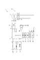
まず、ドライバドリル1の概略構成について説明する。図1に示すように、ドライバドリル1の外郭は、工具本体10によって形成されている。工具本体10は、本体ハウジング11と、ハンドル15とを含む。本体ハウジング11は、所定の駆動軸A1に沿って延在し、モータ2および駆動機構3を収容している。駆動軸A1の延在方向における本体ハウジング11の一端部からは、先端工具(図示略)を着脱可能なチャック37が駆動軸A1に沿って突出している。ハンドル15は、使用者による把持が可能に構成されており、本体ハウジング11から駆動軸A1に交差する方向(概ね直交する方向)に突出している。ハンドル15の基端部(本体ハウジング11に接続する端部)には、使用者による押圧操作(引き操作)が可能なトリガ153が設けられている。また、ハンドル15の突出側の端部(先端部)には、バッテリ装着部157を介して、充電式のバッテリ9が取り外し可能に装着されている。 First, a schematic configuration of the driver drill 1 will be described. As shown in FIG. 1, the outer shell of the driver drill 1 is formed by a tool body 10. As shown in FIG. Tool body 10 includes a body housing 11 and a handle 15 . The body housing 11 extends along a predetermined drive axis A1 and accommodates the motor 2 and the drive mechanism 3 . A chuck 37 to which a tip tool (not shown) can be attached and detached protrudes along the drive shaft A1 from one end of the main body housing 11 in the direction in which the drive shaft A1 extends. The handle 15 is configured to be grippable by the user, and protrudes from the body housing 11 in a direction intersecting (substantially perpendicular to) the drive shaft A1. A trigger 153 that can be pushed (pulled) by the user is provided at the base end of the handle 15 (the end connected to the main body housing 11). A rechargeable battery 9 is detachably attached to the protruding end (tip) of the handle 15 via a battery attachment portion 157 .

なお、以下では、説明の便宜上、駆動軸A1の延在方向をドライバドリル1の前後方向と規定し、チャック37が配置されている側を前側、反対側を後側と規定する。また、駆動軸A1に直交し、ハンドル15の延在方向に対応する方向を上下方向と規定し、本体ハウジング11側を上側、突出端側(バッテリ9が着脱される側)を下側と規定する。また、前後方向および上下方向に直交する方向を左右方向と規定する。 In the following, for convenience of explanation, the direction in which the drive shaft A1 extends is defined as the front-rear direction of the driver drill 1, the side on which the chuck 37 is arranged is defined as the front side, and the opposite side is defined as the rear side. Further, the direction perpendicular to the drive shaft A1 and corresponding to the extending direction of the handle 15 is defined as the vertical direction, the body housing 11 side is defined as the upper side, and the projecting end side (the side where the battery 9 is attached and detached) is defined as the lower side. do. Further, a direction orthogonal to the front-rear direction and the up-down direction is defined as the left-right direction.

以下、ドライバドリル1の物理的構成の詳細について説明する。 Details of the physical configuration of the driver drill 1 will be described below.

ドライバドリル1は、ドリルモードおよびドライバモードという2つの動作モードを有する。ドリルモードは、先端工具の一例であるドリルビットを回転駆動することで、被加工物への穿孔作業を行う動作モードである。ドライバモードは、先端工具の別の一例であるドライバビットを回転駆動することでネジの締結作業を行う動作モードである。図1に示すように、本体ハウジング11の前端部には、駆動軸A1周りに回転可能なモード切替リング117が設けられている。使用者は、モード切替リング117の回転操作により、ドライバドリル1の動作モードを切り替えることができる。 The driver drill 1 has two modes of operation: drill mode and driver mode. The drill mode is an operation mode in which a drill bit, which is an example of a tip tool, is rotationally driven to drill holes in a workpiece. The driver mode is an operation mode in which a screw fastening operation is performed by rotationally driving a driver bit, which is another example of a tip tool. As shown in FIG. 1, the front end portion of the body housing 11 is provided with a mode switching ring 117 rotatable around the drive shaft A1. The user can switch the operation mode of the driver drill 1 by rotating the mode switching ring 117 .

本体ハウジング11の内部構造について説明する。図1に示すように、本体ハウジング11には、駆動源としてのモータ2と、モータ2の動力によって先端工具を駆動するように構成された駆動機構3とが収容されている。 The internal structure of the body housing 11 will be described. As shown in FIG. 1, the body housing 11 accommodates a motor 2 as a drive source and a drive mechanism 3 configured to drive the tip tool by the power of the motor 2 .

本実施形態では、モータ2として、三相ブラシレス直流(DC)モータが採用されている。モータ2は、三相コイルを有するステータ21と、永久磁石を有するロータ23と、ロータ23から延設され、ロータ23と一体的に回転するモータシャフト25とを備えている。モータ2は、本体ハウジング11の後端部内に配置されており、モータシャフト25の回転軸は、駆動軸A1上を延在する。 In this embodiment, a three-phase brushless direct current (DC) motor is used as the motor 2 . The motor 2 includes a stator 21 having three-phase coils, a rotor 23 having permanent magnets, and a motor shaft 25 extending from the rotor 23 and rotating integrally with the rotor 23 . The motor 2 is arranged in the rear end of the body housing 11, and the rotation axis of the motor shaft 25 extends on the drive axis A1.

本実施形態の駆動機構3は、遊星減速機31と、クラッチ機構33と、スピンドル35と、チャック37とを含む。駆動機構3の構成自体は周知であるため、簡単に説明する。 The drive mechanism 3 of this embodiment includes a planetary reduction gear 31 , a clutch mechanism 33 , a spindle 35 and a chuck 37 . Since the configuration of the drive mechanism 3 itself is well known, it will be described briefly.

遊星減速機31は、3段の遊星ギア機構を含む減速機構として構成され、モータ2の前側に配置されている。遊星減速機31は、モータシャフト25から入力されたトルクを増大させ、スピンドル35に出力する。これにより、スピンドル35は、駆動軸A1周りに回転駆動される。チャック37は、スピンドル35と一体的に回転するように、スピンドル35に同軸状に連結されている。なお、本体ハウジング11の上面には、変速レバー311が設けられている。変速レバー311は、前後方向に移動可能に配置されており、遊星減速機31の切替機構(図示略)に連結されている。変速レバー311の位置が切り替えられると、切替機構を介して遊星減速機31の減速比(つまり、スピンドル35の回転数)が切り替えられる。クラッチ機構33は、遊星減速機31の前側に配置されている。クラッチ機構33は、動作モードとしてドライバモードが選択されている場合、遊星減速機31から出力されるトルクが設定された閾値に達すると、スピンドル35へのトルク伝達を遮断するように構成されている。トルクの閾値は、本体ハウジング11の前端部に設けられたトルク調整リング115の回転操作により設定される。 The planetary reduction gear 31 is configured as a reduction mechanism including a three-stage planetary gear mechanism, and is arranged on the front side of the motor 2 . The planetary speed reducer 31 increases the torque input from the motor shaft 25 and outputs it to the spindle 35 . Thereby, the spindle 35 is rotationally driven around the drive axis A1. The chuck 37 is coaxially connected to the spindle 35 so as to rotate together with the spindle 35 . A shift lever 311 is provided on the upper surface of the body housing 11 . The shift lever 311 is arranged so as to be movable in the front-rear direction, and is connected to a switching mechanism (not shown) of the planetary reduction gear 31 . When the position of the shift lever 311 is switched, the speed reduction ratio of the planetary speed reducer 31 (that is, the rotation speed of the spindle 35) is switched via the switching mechanism. The clutch mechanism 33 is arranged on the front side of the planetary reduction gear 31 . The clutch mechanism 33 is configured to cut off torque transmission to the spindle 35 when the torque output from the planetary reduction gear 31 reaches a set threshold when the driver mode is selected as the operation mode. . The torque threshold is set by rotating a torque adjusting ring 115 provided at the front end of the body housing 11 .

ハンドル15およびその内部構造について説明する。図1に示すように、ハンドル15は、概ね上下方向に延在する筒状の把持部151と、把持部151の下端部に接続し、ハンドル15の下端部を構成する矩形箱状のコントローラ収容部155とを含む。 The handle 15 and its internal structure will be described. As shown in FIG. 1, the handle 15 includes a cylindrical grip portion 151 extending generally in the vertical direction, and a rectangular box-shaped controller housing that is connected to the lower end of the grip portion 151 and constitutes the lower end of the handle 15 . section 155;

トリガ153は、把持部151の上端部の前側に設けられている。把持部151内には、トリガスイッチ154が収容されている。トリガスイッチ154は、常時にはオフ状態で維持され、トリガ153の押圧操作に応じてオン状態とされる。トリガスイッチ154は、オン状態とされた場合、図示しない配線を介して、トリガ153の操作量に応じた信号をコントローラ5に出力するように構成されている。 The trigger 153 is provided on the front side of the upper end portion of the grip portion 151 . A trigger switch 154 is accommodated in the grip portion 151 . The trigger switch 154 is normally kept off, and is turned on when the trigger 153 is pressed. The trigger switch 154 is configured to output a signal corresponding to the amount of operation of the trigger 153 to the controller 5 via wiring (not shown) when turned on.

コントローラ収容部155内には、モータ2の駆動制御等、ドライバドリル1の各種動作を制御するように構成されたコントローラ5が収容されている。なお、コントローラ5は、ケース50内に配置されたメイン基板に搭載されている。なお、本実施形態では、コントローラ5は、CPU501、ROM502、RAM503、タイマ504、メモリ(詳細には、不揮発性メモリ)505を含むマイクロコンピュータとして構成されている(図2参照)。また、本実施形態では、メイン基板には、加速度センサ71も搭載されている。加速度センサ71は、工具本体10と一体的に動くコントローラ5の加速度を検出し、図示しない配線を介して、加速度の検出値を示す信号をコントローラ5に出力するように構成されている。 A controller 5 configured to control various operations of the driver drill 1 such as driving control of the motor 2 is accommodated in the controller accommodating portion 155 . Note that the controller 5 is mounted on a main board arranged within the case 50 . In this embodiment, the controller 5 is configured as a microcomputer including a CPU 501, a ROM 502, a RAM 503, a timer 504, and a memory (specifically, a non-volatile memory) 505 (see FIG. 2). Further, in this embodiment, an acceleration sensor 71 is also mounted on the main board. The acceleration sensor 71 is configured to detect the acceleration of the controller 5 that moves integrally with the tool body 10 and output a signal indicating the detected value of the acceleration to the controller 5 via wiring (not shown).

更に、コントローラ収容部155の上部には、使用者による外部操作が可能な操作部73が設けられている。詳細な図示は省略するが、操作部73は、各種情報の入力を受け付ける押しボタンを有する。なお、操作部73は、押しボタンに代えて、使用者の外部操作が可能なスライドレバー、タッチパッド等を備えていてもよい。操作部73は、図示しない配線を介してコントローラ5に接続されており、入力された情報を示す信号をコントローラ5に出力するように構成されている。コントローラ収容部155の下端部には、バッテリ装着部157が設けられている。バッテリ装着部157の構成自体は周知であるため、ここでの説明は省略する。 Furthermore, an operation unit 73 that can be externally operated by the user is provided on the upper portion of the controller housing unit 155 . Although detailed illustration is omitted, the operation unit 73 has push buttons for receiving input of various kinds of information. Note that the operation unit 73 may include a slide lever, a touch pad, or the like that can be externally operated by the user, instead of the push button. The operation unit 73 is connected to the controller 5 via wiring (not shown), and is configured to output a signal indicating input information to the controller 5 . A battery mounting portion 157 is provided at the lower end portion of the controller housing portion 155 . Since the configuration itself of the battery mounting portion 157 is well known, the description thereof is omitted here.

ドライバドリル1の電気的構成について説明する。 An electrical configuration of the driver drill 1 will be described.

図2に示すように、コントローラ5には、三相インバータ51、ホールセンサ53、電流検出アンプ55、トリガスイッチ154、加速度センサ71、および操作部73が電気的に接続されている。 As shown in FIG. 2, the controller 5 is electrically connected to a three-phase inverter 51, a hall sensor 53, a current detection amplifier 55, a trigger switch 154, an acceleration sensor 71, and an operation section 73.

三相インバータ51は、6つの半導体スイッチング素子を用いた三相ブリッジ回路を備えている。ホールセンサ53は、モータ2の各相に対応して配置される3つのホール素子を備えており、ロータ23の回転位置を示す信号を、コントローラ5に出力するように構成されている。コントローラ5は、ホールセンサ53から入力された信号(ロータ23の回転位置)に応じて、三相インバータ51を介してモータ2への通電を制御する。本実施形態では、コントローラ5は、三相インバータ51を介してモータ2を波駆動するように構成されており、各相端子の印加電圧はロータ23の回転位置に応じて変化する。また、本実施形態では、コントローラ5は、トリガスイッチ154からの信号(トリガ153の操作量)に応じてPMW(パルス幅変調)信号を生成し、三相インバータ51に出力することで、スイッチング素子をPMW制御する。その結果、トリガ153の操作量に応じて、モータ2へ印加される実質的な電圧、つまりモータ2の回転数が調整される。電流検出アンプ55は、モータ2に流れる電流をシャント抵抗によって電圧に変換し、更にアンプによって増幅した信号をコントローラ5に出力する。 The three-phase inverter 51 has a three-phase bridge circuit using six semiconductor switching elements. The Hall sensor 53 has three Hall elements arranged corresponding to each phase of the motor 2 and is configured to output a signal indicating the rotational position of the rotor 23 to the controller 5 . The controller 5 controls energization to the motor 2 via the three-phase inverter 51 according to a signal (rotational position of the rotor 23) input from the hall sensor 53. FIG. In this embodiment, the controller 5 is configured to wave-drive the motor 2 via the three-phase inverter 51 , and the voltage applied to each phase terminal changes according to the rotational position of the rotor 23 . Further, in the present embodiment, the controller 5 generates a PMW (pulse width modulation) signal according to the signal from the trigger switch 154 (the operation amount of the trigger 153), and outputs it to the three-phase inverter 51, so that the switching element is PWM controlled. As a result, the substantial voltage applied to the motor 2, that is, the rotation speed of the motor 2 is adjusted according to the amount of operation of the trigger 153. FIG. A current detection amplifier 55 converts the current flowing through the motor 2 into a voltage using a shunt resistor, and outputs a signal amplified by an amplifier to the controller 5 .

以下、コントローラ5によるドライバドリル1の動作制御の概要について説明する。 An outline of operation control of the driver drill 1 by the controller 5 will be described below.

本実施形態では、コントローラ5(詳細には、CPU501)は、先端工具に加えられる負荷(モータ2に加えられる負荷ともいえる)に対応する情報(指標値、物理量)(以下、単に負荷情報という)を監視し、負荷情報に応じて、モータ2への通電角を制御するように構成されている。これは、モータ2の動作特性を、通電角に応じて変化させるためである。具体的には、通電角を小さくすると、モータ2の出力トルクが上昇する一方で、モータ2の回転数は低下する。反対に、通電角を大きくすると、モータ2の出力トルクが低下する一方で、モータ2の回転数は上昇する。そこで、本実施形態では、コントローラ5は、通電角を120度または150度に設定可能とされており、先端工具に加えられる負荷が比較的大きい場合には、モータ2の出力トルクを優先して、通電角を、より小さい120度に設定する。反対に、先端工具に加えられる負荷が比較的小さい場合には、コントローラ5は、モータ2の回転数(先端工具の高速駆動)を優先して、通電角を、より大きい150度に設定する。 In this embodiment, the controller 5 (specifically, the CPU 501) provides information (index value, physical quantity) (hereinafter simply referred to as load information) corresponding to the load applied to the tip tool (which can also be said to be the load applied to the motor 2). is monitored, and the energization angle to the motor 2 is controlled according to the load information. This is for changing the operating characteristics of the motor 2 according to the conduction angle. Specifically, when the energization angle is decreased, the output torque of the motor 2 increases, while the rotational speed of the motor 2 decreases. Conversely, when the conduction angle is increased, the output torque of the motor 2 decreases, while the rotational speed of the motor 2 increases. Therefore, in the present embodiment, the controller 5 can set the conduction angle to 120 degrees or 150 degrees, and when the load applied to the tip tool is relatively large, priority is given to the output torque of the motor 2. , the conduction angle is set to a smaller 120 degrees. Conversely, when the load applied to the tip tool is relatively small, the controller 5 gives priority to the rotational speed of the motor 2 (high-speed drive of the tip tool) and sets the conduction angle to a larger 150 degrees.

以下の説明では、120度の通電角で駆動すること、および150度の通電角で駆動することを、夫々、高トルクモード駆動および低トルクモード駆動とも称する。なお、上述のように、本実施形態では、トリガ153の操作量に応じて回転数が制御されるが、トリガ153の操作量が同じ場合には、高トルクモード駆動時の方が、低トルクモード駆動時よりも出力トルクが高く、モータ2の回転数が低いことになる。 In the following description, driving at a conduction angle of 120 degrees and driving at a conduction angle of 150 degrees are also referred to as high torque mode driving and low torque mode driving, respectively. As described above, in the present embodiment, the number of rotations is controlled according to the amount of operation of the trigger 153, but when the amount of operation of the trigger 153 is the same, the torque is lower in the high-torque mode driving. The output torque is higher and the rotation speed of the motor 2 is lower than in mode driving.

なお、三相ブラシレスモータでは、モータ2に加えられる負荷が大きくなるほど、モータ2の電流が増大するとともに、モータ2の回転数が低下することは周知である。また、このとき、モータ2の電流の増大に応じてバッテリ9の電流も増大するとともに、バッテリ9の電圧が低下することも周知である。よって、コントローラ5が監視する負荷情報としては、例えば、モータ2の電流値、モータ2の回転数、バッテリ9の電流値、バッテリ9の電圧値を好適に採用することができる。詳細は後述するが、本実施形態では、負荷情報として、電流検出アンプ55によって検出されるモータ2の電流値が採用されている。コントローラ5は、モータ2の駆動中、電流検出アンプ55によって検出されるモータ2の電流値を監視し、電流値が所定の閾値を超えるか否かに応じて、通電角を120度と150度の間で変更する。なお、このようなモータ2の通電角の設定方法は、例えば、国際公開WO2012/108415に開示されている。 It is well known that in a three-phase brushless motor, as the load applied to the motor 2 increases, the current of the motor 2 increases and the rotation speed of the motor 2 decreases. It is also well known that at this time, as the current of the motor 2 increases, the current of the battery 9 also increases and the voltage of the battery 9 decreases. Therefore, as the load information monitored by the controller 5, for example, the current value of the motor 2, the rotation speed of the motor 2, the current value of the battery 9, and the voltage value of the battery 9 can be preferably used. Although the details will be described later, in this embodiment, the current value of the motor 2 detected by the current detection amplifier 55 is used as the load information. The controller 5 monitors the current value of the motor 2 detected by the current detection amplifier 55 while the motor 2 is being driven, and adjusts the conduction angle to 120 degrees or 150 degrees depending on whether the current value exceeds a predetermined threshold value. change between A method for setting the conduction angle of the motor 2 is disclosed, for example, in International Publication WO2012/108415.

また、本実施形態では、コントローラ5(詳細には、CPU501)は、負荷情報と、工具本体10の駆動軸A1周りの回転状態に対応する情報(指標、物理量)(以下、単に回転状態情報という)を監視し、これらの情報に基づいて、先端工具のロックに起因して工具本体10に過度な回転が生じるか否か(キックバック発生の可能性)を判断するように構成されている。そして、過度な回転が生じる(キックバック発生の可能性が比較的高い)と判断すると、モータ2の駆動を停止することで、先端工具の回転駆動を停止させるように構成されている。 In the present embodiment, the controller 5 (specifically, the CPU 501) provides load information and information (index, physical quantity) corresponding to the rotational state of the tool body 10 around the drive axis A1 (hereinafter simply referred to as rotational state information). ), and based on this information, it is determined whether excessive rotation occurs in the tool body 10 due to locking of the tip tool (possibility of occurrence of kickback). When it is determined that excessive rotation will occur (the possibility of kickback occurring is relatively high), the drive of the motor 2 is stopped, thereby stopping the rotating drive of the tip tool.

本実施形態では、上述のように、電流検出アンプ55によって検出されるモータ2の電流値が、負荷情報として用いられる。また、回転状態情報としては、例えば、速度、加速度、角速度、角加速度を好適に採用することができる。本実施形態では、加速度センサ71によって検出される加速度が、回転状態情報として用いられる。詳細は後述するが、コントローラ5は、これらの情報に基づいて、先端工具のロックに起因する過度な回転が生じるか否かを判断する。なお、このような過度な回転の判断方法は、例えば、特開2011―93073号公報、特開2013―244581号公報に開示されている。 In this embodiment, as described above, the current value of the motor 2 detected by the current detection amplifier 55 is used as load information. Also, speed, acceleration, angular velocity, and angular acceleration, for example, can be preferably used as the rotation state information. In this embodiment, the acceleration detected by the acceleration sensor 71 is used as rotation state information. Although the details will be described later, the controller 5 determines whether excessive rotation due to locking of the tool bit occurs based on these pieces of information. Note that methods for determining such excessive rotation are disclosed in, for example, Japanese Patent Application Laid-Open No. 2011-93073 and Japanese Patent Application Laid-Open No. 2013-244581.

以下、図3~図5を参照して、コントローラ5(詳細には、CPU501)によって実行されるモータ2の駆動制御処理の詳細と、処理中のドライバドリル1の具体的な動作について説明する。なお、モータ2の駆動制御処理は、トリガ153が引き操作され、トリガスイッチ154がオン状態とされると開始され、モータ2の駆動が停止されると終了される。なお、以下の説明および図では、処理中の各「ステップ」を「S」と簡略表記する。 The details of the drive control process for the motor 2 executed by the controller 5 (specifically, the CPU 501) and the specific operation of the driver drill 1 during the process will be described below with reference to FIGS. 3 to 5. FIG. The drive control process for the motor 2 is started when the trigger 153 is pulled and the trigger switch 154 is turned on, and ends when the drive of the motor 2 is stopped. In the following description and drawings, each "step" during processing is abbreviated as "S".

図3に示すように、処理が開始されると、CPU501は、三相インバータ51を介してモータ2に通電し、トリガ153の操作量に応じた回転数でモータ2の駆動を開始する(S100)。なお、本実施形態では、通電角の初期値は150度に設定されており、モータ2は、低トルクモードで駆動される。CPU501は、電流検出アンプ55から出力される信号に基づいて、モータ2の電流値を特定し(S200)、更に、加速度センサ71から出力される信号に基づいて、加速度の検出値を特定する(S300)。 As shown in FIG. 3, when the process is started, the CPU 501 energizes the motor 2 via the three-phase inverter 51, and starts driving the motor 2 at the rotation speed corresponding to the operation amount of the trigger 153 (S100). ). In this embodiment, the initial value of the conduction angle is set to 150 degrees, and the motor 2 is driven in the low torque mode. The CPU 501 identifies the current value of the motor 2 based on the signal output from the current detection amplifier 55 (S200), and further identifies the detected acceleration value based on the signal output from the acceleration sensor 71 (S200). S300).

CPU501は、S200で特定されたモータ2の電流値に基づいて、モータ2への通電角を設定する通電角設定処理を行う(S400)。図4に示すように、通電角設定処理では、CPU501は、電流値が閾値よりも大きいか否かを判断する(S401)。そして、電流値が閾値よりも大きい場合(S401:YES)、つまり、先端工具およびモータ2に加えられる負荷が比較的大きい場合には、通電角を120度に設定する(S402)。一方、電流値が閾値以下の場合(S401:NO)、つまり、先端工具およびモータ2に加えられる負荷が比較的小さい場合には、通電角を150度に設定する(S403)。以降、CPU501は、設定した通電角でモータ2を駆動する。なお、S401で電流値と比較される閾値は、予め定められ、例えば、ROM502またはメモリ505に記憶されていればよい。なお、S402またはS403において、通電角がその時点で設定されている角度から変更される場合には、進角もあわせて変更されることが好ましい。具体的な進角の値は、ドライバドリル1の構造、機能、要求特性に応じて予め設定され、通電角に対応付けて、例えば、ROM502またはメモリ505に記憶されていればよい。 The CPU 501 performs conduction angle setting processing for setting the conduction angle to the motor 2 based on the current value of the motor 2 specified in S200 (S400). As shown in FIG. 4, in the conduction angle setting process, the CPU 501 determines whether or not the current value is greater than a threshold (S401). Then, if the current value is greater than the threshold (S401: YES), that is, if the load applied to the tip tool and the motor 2 is relatively large, the energization angle is set to 120 degrees (S402). On the other hand, if the current value is equal to or less than the threshold value (S401: NO), that is, if the load applied to the tip tool and the motor 2 is relatively small, the conduction angle is set to 150 degrees (S403). Thereafter, the CPU 501 drives the motor 2 at the set conduction angle. Note that the threshold value to be compared with the current value in S401 is determined in advance and may be stored in the ROM 502 or the memory 505, for example. In addition, in S402 or S403, when the conduction angle is changed from the angle set at that time, it is preferable that the advance angle is also changed. A specific advance angle value may be set in advance according to the structure, function, and required characteristics of the driver drill 1, and stored in the ROM 502 or the memory 505, for example, in association with the conduction angle.

図3に示すように、CPU501は、通電角設定処理に続き、S200で特定されたモータ2の電流値と、S300で特定された加速度に基づいて、工具本体10の回転状態を推定する回転状態推定処理を行う(S500)。なお、本実施形態では、工具本体10の回転の開始から加速度の検出を経て、工具本体10が停止するまでに回転すると予想される角度(以下、予想回転角度という)が、工具本体10の過度な回転状態、言い換えると過度な回転の度合いを示す指標値の一例として算出される。なお、この予想回転角度の算出方法は、特開2013―244581号公報に開示されている方法と基本的に同じである。 As shown in FIG. 3, following the energization angle setting process, the CPU 501 performs a rotational state estimation for estimating the rotational state of the tool body 10 based on the current value of the motor 2 identified in S200 and the acceleration identified in S300. An estimation process is performed (S500). In the present embodiment, the angle at which the tool body 10 is expected to rotate from the start of rotation of the tool body 10 through acceleration detection until the tool body 10 stops (hereinafter referred to as the expected rotation angle) It is calculated as an example of an index value indicating an excessive rotation state, in other words, the degree of excessive rotation. Note that the method for calculating this expected rotation angle is basically the same as the method disclosed in Japanese Patent Application Laid-Open No. 2013-244581.

図5に示すように、回転状態推定処理では、CPU501はまず、使用者が工具本体10を保持する力に対応する情報の一例としての保持トルクを推定する(S501)。なお、保持トルクとは、工具本体10を保持する使用者によって、工具本体10に加えられるトルク(抵抗トルク)であって、工具本体10に加えられる外力(外部からの抵抗力)ともいえる。CPU501は、モータ2の既知の特性に基づき、モータ2の電流値から、モータトルクを得ることができる。また、加速度センサ71から出力された単位時間ごとの加速度を演算処理することで、角加速度を得ることができる。CPU501は、慣性モーメント、角加速度、モータトルク、および保持トルクの間の所定の関係から、保持トルクを推定することができる。なお、使用者の保持トルクは、工具本体10と使用者との位置関係等に応じて短い時間で大きく変化しうるため、ここでは、短い積分時間を用いて保持トルクの積分値を推定する。 As shown in FIG. 5, in the rotational state estimation process, the CPU 501 first estimates a holding torque as an example of information corresponding to the force with which the user holds the tool body 10 (S501). The holding torque is the torque (resistance torque) applied to the tool body 10 by the user holding the tool body 10, and can also be said to be an external force (resistance force from the outside) applied to the tool body 10. The CPU 501 can obtain the motor torque from the current value of the motor 2 based on the known characteristics of the motor 2 . Further, the angular acceleration can be obtained by arithmetically processing the acceleration output from the acceleration sensor 71 for each unit time. The CPU 501 can estimate the holding torque from a predetermined relationship between moment of inertia, angular acceleration, motor torque, and holding torque. Since the user's holding torque can change greatly in a short time depending on the positional relationship between the tool body 10 and the user, the integral value of the holding torque is estimated using a short integration time.

更に、CPU501は、予想回転角度を推定する(S502)。予想回転速度は、すでに回転している角度、モータ2への通電を停止するまでに回転する角度、モータ2への通電停止後に回転する角度の合算値である。なお、すでに回転している角度は、角加速度を適宜演算処理することで得られる。また、モータ2への通電を停止するまでに回転する角度は、工具本体10が、角加速度の積分値として得られる角速度で等速運動するとして、停止までに要する時間から推定することができる。モータ2への通電停止後に回転する角度は、角速度で運動中の工具本体10が、S501で得られた使用者の保持トルクによって停止するとして、慣性モーメント、角速度、および保持トルクの間の所定の関係から推定することができる。 Furthermore, the CPU 501 estimates the expected rotation angle (S502). The expected rotation speed is the sum of the angle at which the motor 2 is already rotating, the angle at which the motor 2 will rotate until the power supply to the motor 2 is stopped, and the angle at which the motor 2 will rotate after the power supply to the motor 2 is stopped. The already rotated angle can be obtained by appropriately processing the angular acceleration. Further, the angle of rotation until the motor 2 is stopped can be estimated from the time required until the tool body 10 stops, assuming that the tool body 10 is in uniform motion at an angular velocity obtained as an integral value of the angular acceleration. Assuming that the tool body 10 moving at the angular velocity is stopped by the user's holding torque obtained in S501, the angle of rotation after the power supply to the motor 2 is stopped is a predetermined value between the moment of inertia, the angular velocity, and the holding torque. can be inferred from the relationship.

図3に示すように、CPU501は、回転状態推定処理(S500)の後、予想回転速度に基づいて、先端工具のロックに起因する工具本体10の過度な回転が生じるか否かを判断する(S600)。より詳細には、CPU501は、予想回転速度が閾値よりも大きい場合には、過度な回転が生じると判断し(S600:YES)、トリガスイッチ154の状態にかかわらず、強制的にモータ2の駆動を停止する(S800)。なお、このとき、CPU501は、モータ2への通電を停止するのみならず、モータ2を電気的に制動することが好ましい。なお、S600で予想回転角度と比較される過度な回転に関する判断用の閾値は、予め定められ、例えば、ROM502またはメモリ505に記憶されていればよい。 As shown in FIG. 3, after the rotation state estimation process (S500), the CPU 501 determines whether excessive rotation of the tool body 10 due to locking of the tip tool occurs based on the expected rotation speed ( S600). More specifically, when the predicted rotational speed is greater than the threshold, the CPU 501 determines that excessive rotation will occur (S600: YES), and forcibly drives the motor 2 regardless of the state of the trigger switch 154. is stopped (S800). At this time, it is preferable that the CPU 501 not only stop energizing the motor 2 but also electrically brake the motor 2 . It should be noted that the threshold value for judging excessive rotation that is compared with the predicted rotation angle in S600 may be determined in advance and stored in the ROM 502 or the memory 505, for example.

一方、CPU501は、予想回転速度が閾値以下の場合には、過度な回転が生じていないと判断し(S600:NO)、トリガスイッチ154がオフ状態か否かを判断する(S700)。トリガスイッチ154がオン状態の場合(S700:NO)、CPU501は、S200の処理に戻る。トリガスイッチ154がオン状態の間、CPU501は、モータ2の電流値と加速度を監視し、過度な回転が生じなければ、先端工具への負荷に応じて高トルクモードと低トルクモードとを適宜切り替えながら、モータ2の駆動を継続する。この間、先端工具が回転駆動される。トリガスイッチ154がオフ状態とされると(S700:YES)、CPU501は、モータ2の駆動を停止する(S800)。 On the other hand, when the predicted rotational speed is equal to or less than the threshold, the CPU 501 determines that excessive rotation has not occurred (S600: NO), and determines whether the trigger switch 154 is off (S700). If the trigger switch 154 is on (S700: NO), the CPU 501 returns to the process of S200. While the trigger switch 154 is in the ON state, the CPU 501 monitors the current value and acceleration of the motor 2, and switches appropriately between the high torque mode and the low torque mode according to the load on the tip tool if excessive rotation does not occur. while continuing to drive the motor 2 . During this time, the tip tool is rotationally driven. When the trigger switch 154 is turned off (S700: YES), the CPU 501 stops driving the motor 2 (S800).

以上に説明したように、本実施形態のドライバドリル1は、工具本体10と、ブラシレスモータであるモータ2と、先端工具に加えられる負荷に対応するモータ電流値を検出する電流検出アンプ55と、工具本体10の駆動軸A1周りの回転状態に対応する加速度を検出する加速度センサ71と、ドライバドリル1の動作を制御するコントローラ5(CPU501)とを備えている。CPU501は、モータ電流値に応じてモータ2への通電角を設定することで、モータ2の出力トルクおよび回転数を制御する。また、電流検出アンプ55によって検出されたモータ電流値は、加速度センサ71によって検出された加速度と共に、先端工具のロックに起因する工具本体10の過度な回転が生じるか否かの判断にも利用される。CPU501は、モータ電流値と加速度に基づいて、工具本体10の過度な回転の可能性の適切な判断を行うことができる。このように、本実施形態のドライバドリル1では、2つの検出器(電流検出アンプ55と加速度センサ71)を用いて、工具本体10の過度な回転の可能性の適切な判断のみならず、先端工具に加えられる負荷に応じたモータ2の出力トルクおよび回転数の制御が可能な合理的な構成が実現されている。 As described above, the driver drill 1 of this embodiment includes the tool body 10, the motor 2 which is a brushless motor, the current detection amplifier 55 for detecting the motor current value corresponding to the load applied to the tip tool, An acceleration sensor 71 for detecting acceleration corresponding to the rotational state of the tool body 10 around the drive axis A1, and a controller 5 (CPU 501) for controlling the operation of the driver drill 1 are provided. The CPU 501 controls the output torque and rotation speed of the motor 2 by setting the energization angle to the motor 2 according to the motor current value. In addition, the motor current value detected by the current detection amplifier 55 is used together with the acceleration detected by the acceleration sensor 71 to determine whether excessive rotation of the tool body 10 due to locking of the tip tool occurs. be. The CPU 501 can appropriately determine the possibility of excessive rotation of the tool body 10 based on the motor current value and acceleration. Thus, in the driver drill 1 of the present embodiment, two detectors (the current detection amplifier 55 and the acceleration sensor 71) are used to appropriately determine the possibility of excessive rotation of the tool body 10 and also A rational configuration is realized that allows control of the output torque and rotation speed of the motor 2 according to the load applied to the tool.

[第2実施形態]
以下、図6を参照して、第2実施形態に係るドライバドリルについて説明する。本実施形態のドライバドリルの物理的構成および電気的構成は、第1実施形態のドライバドリル1(図1および図2参照)と実質的に同一であるが、コントローラ5(CPU501)によって行われるモータ2の駆動制御処理の内容の一部が、第1実施形態とは異なっている。よって、以下では、第1実施形態と同一の構成および処理の内容については、同じ符号およびステップ番号を付して、適宜、説明および図示を省略または簡略化し、主に、処理の内容において異なる点について説明する。この点については、これ以降の実施形態でも同様である。
[Second embodiment]
A driver drill according to a second embodiment will be described below with reference to FIG. The physical and electrical configuration of the driver drill of this embodiment is substantially the same as the driver drill 1 of the first embodiment (see FIGS. 1 and 2), but the motor control performed by the controller 5 (CPU 501) 2 is different from the first embodiment. Therefore, in the following description, the same reference numerals and step numbers are assigned to the same configuration and processing content as in the first embodiment, and the description and illustrations are omitted or simplified as appropriate, and the main differences are in the processing content. will be explained. This point also applies to the subsequent embodiments.

まず、本実施形態におけるモータ2の駆動制御の概要について説明する。本実施形態でも、第1実施形態と同様、CPU501は、モータ2の電流値に基づいて通電角を設定し、モータ2を駆動するとともに、電流値および加速度に基づいて、過度な回転が生じるか否かを判断するように構成されている。更に、本実施形態では、CPU501は、モータ2の駆動中に、通電角の設定履歴に基づいて、過度な回転が生じるか否かの判断に用いられる閾値を変更するように構成されている。このため、CPU501は、通電角設定処理を行う度に、通電角の設定結果を記憶するように構成されている。 First, an outline of drive control of the motor 2 in this embodiment will be described. In this embodiment, as in the first embodiment, the CPU 501 sets the conduction angle based on the current value of the motor 2, drives the motor 2, and determines whether excessive rotation occurs based on the current value and acceleration. It is configured to determine whether or not Furthermore, in this embodiment, the CPU 501 is configured to change the threshold value used to determine whether or not excessive rotation will occur while the motor 2 is being driven, based on the setting history of the conduction angle. Therefore, the CPU 501 is configured to store the setting result of the conduction angle each time the conduction angle setting process is performed.

以下、本実施形態におけるモータ2の駆動制御処理の詳細について説明する。図6に示すように、トリガスイッチ154がオン状態とされて処理が開始されると、CPU501は、低トルクモードでモータ2の駆動を開始する(S100)。そして、モータ2の電流値および加速度を特定し、更に、電流値に基づいて通電角を設定する(S200、S300、S400)。本実施形態では、RAM503には、通電角の設定履歴として、通電角設定処理の実行回数と、通電角が120度に設定された回数が記憶される記憶エリアが設けられている。なお、本実施形態では、処理の開始時にRAM503は初期化され、いずれの回数も初期値のゼロとされる。CPU501は、通電角設定処理の後、RAM503に記憶された、通電角設定処理の実行回数および120度に設定された回数を更新することで、設定履歴を更新する(S411)。 Details of the drive control process for the motor 2 in this embodiment will be described below. As shown in FIG. 6, when the trigger switch 154 is turned on and processing is started, the CPU 501 starts driving the motor 2 in the low torque mode (S100). Then, the current value and acceleration of the motor 2 are specified, and the conduction angle is set based on the current value (S200, S300, S400). In this embodiment, the RAM 503 is provided with a storage area for storing the number of times the conduction angle setting process is executed and the number of times the conduction angle is set to 120 degrees as the conduction angle setting history. Note that in this embodiment, the RAM 503 is initialized at the start of processing, and the number of times is set to an initial value of zero. After the conduction angle setting process, the CPU 501 updates the setting history by updating the number of executions of the conduction angle setting process and the number of times set to 120 degrees stored in the RAM 503 (S411).

更に、CPU501は、通電角設定処理の実行回数に対し、通電角が120度に設定された回数の割合、つまり、通電角が120度に設定された頻度(以下、高トルクモード頻度という)を算出し(S412)、高トルクモード頻度を閾値と比較する(S413)。なお、S413で用いられる閾値は、予め定められ、例えば、ROM502またはメモリ505に記憶されていればよい。高トルクモード頻度が閾値以下の場合(S413:NO)、CPU501は、S600で予想回転角度と比較される閾値(過度な回転の判断用の閾値)を、第1閾値に設定する(S414)。高トルクモード頻度が閾値よりも高い場合(S413:YES)、CPU501は、過度な回転の判断用の閾値を、第2閾値に設定する(S415)。なお、S414またはS415で設定された過度な回転の判断用の閾値は、RAM503の所定の記憶エリアに記憶される。 Further, the CPU 501 determines the ratio of the number of times the conduction angle is set to 120 degrees to the number of times the conduction angle setting process is executed, that is, the frequency at which the conduction angle is set to 120 degrees (hereinafter referred to as high torque mode frequency). (S412), and compares the high torque mode frequency with a threshold value (S413). Note that the threshold used in S413 may be determined in advance and stored in the ROM 502 or the memory 505, for example. If the high torque mode frequency is equal to or less than the threshold (S413: NO), the CPU 501 sets the threshold (threshold for judging excessive rotation) to be compared with the predicted rotation angle in S600 to the first threshold (S414). If the high torque mode frequency is higher than the threshold (S413: YES), the CPU 501 sets the threshold for judging excessive rotation to the second threshold (S415). Note that the threshold for judging excessive rotation set in S414 or S415 is stored in a predetermined storage area of the RAM 503 .

なお、過度な回転の判断用の第2閾値は、第1閾値よりも大きい値である。第1閾値は、比較的力が弱い使用者(つまり、比較的小さい保持トルクしか発揮できない使用者)を考慮して設定された初期値である。よって、第1閾値に基づく過度な回転の判断基準は、比較的低い。これに対し、第2閾値は、比較的力が強い使用者(つまり、比較的大きい保持トルクを定常的に発揮できる使用者)を考慮して設定されているため、第2閾値に基づく過度な回転の判断基準は、比較的高い。つまり、第2閾値に基づく判断では、第1閾値に基づく判断に比べると、過度な回転が生じると判断されにくくなる。 Note that the second threshold for judging excessive rotation is a value larger than the first threshold. The first threshold is an initial value that is set in consideration of a user with relatively weak force (that is, a user who can exert only a relatively small holding torque). Therefore, the criterion for excessive rotation based on the first threshold is relatively low. On the other hand, the second threshold is set in consideration of a relatively strong user (that is, a user who can steadily exert a relatively large holding torque). The criterion for rotation is relatively high. In other words, in the determination based on the second threshold, it is less likely that excessive rotation will occur compared to the determination based on the first threshold.

CPU501は、その後、回転状態推定処理において予想回転角度を推定し(S500)、S414またはS415で設定された閾値(第1閾値または第2閾値)との比較結果に応じて、過度な回転が生じるか否かを判断する(S600)。そして、過度な回転は生じていないと判断し(S600:NO)、トリガスイッチ154がオフ状態でなければ(S700:NO)、S200の処理に戻る。過度な回転が生じると判断した場合には(S600:YES)モータ2の駆動を停止する(S800)。また、過度な回転は生じていないがトリガスイッチ154がオフ状態とされた場合も(S700:YES)、モータ2の駆動を停止する(S800)。 The CPU 501 then estimates the expected rotation angle in the rotation state estimation process (S500), and depending on the result of comparison with the threshold value (first threshold value or second threshold value) set in S414 or S415, excessive rotation occurs. (S600). Then, it is determined that excessive rotation has not occurred (S600: NO), and if the trigger switch 154 is not in the OFF state (S700: NO), the process returns to S200. If it is determined that excessive rotation will occur (S600: YES), the drive of the motor 2 is stopped (S800). Also, when the trigger switch 154 is turned off (S700: YES), the driving of the motor 2 is stopped (S800).

以上に説明したように、本実施形態では、CPU501は、モータ2への通電角を、120度または150度に設定可能である。また、CPU501は、モータ電流値および加速度に基づいて、工具本体10の回転度合いを示す指標値としての予想回転角度を算出し、予想回転角度が閾値を超える場合に、先端工具のロックに起因する工具本体10の過度な回転が生じると判断する。更に、CPU501は、ドライバドリル1の使用状態に関する情報として、先端工具およびモータ2への負荷に応じて設定される通電角(詳細には、通電角が120度に設定された頻度である高トルクモード頻度)を監視しており、高トルクモード頻度に基づいて、過度な回転が生じるか否かの判断基準(具体的には、過度な回転の判断用の閾値)を変更する。 As described above, in this embodiment, the CPU 501 can set the energization angle to the motor 2 to 120 degrees or 150 degrees. Further, the CPU 501 calculates an expected rotation angle as an index value indicating the degree of rotation of the tool body 10 based on the motor current value and the acceleration. It is determined that excessive rotation of the tool body 10 occurs. Further, the CPU 501 stores the information about the usage state of the driver drill 1 as the conduction angle set according to the load on the tip tool and the motor 2 (specifically, the high torque angle at which the conduction angle is set to 120 degrees). mode frequency), and based on the high torque mode frequency, the criterion for determining whether excessive rotation occurs (specifically, the threshold value for determining excessive rotation) is changed.

通電角が120度に設定される場合、先端工具には、150度に設定される場合よりも大きい負荷が加えられている状態である。つまり、高トルクモード頻度は、実際に作業が遂行される時間に対し、先端工具に加えられる負荷が比較的大きい時間の割合に概ね対応するといえる。よって、本実施形態の処理によれば、先端工具に加えられる負荷の状況に応じて、過度な回転が生じる可能性の判断基準を柔軟に変更することができる。特に、本実施形態では、CPU501は、高トルクモード頻度が閾値を超える場合、予想回転角度用の閾値を、初期値である第1閾値よりも大きい第2閾値に変更する。高トルクモード頻度が高くなるほど、先端工具に加えられる負荷が比較的大きい時間の割合が大きくなるといえる。このような場合、使用者が、先端工具に高負荷がかかる作業に耐えうるだけの保持力を、ある程度定常的に発揮できると推定できる。このため、本実施形態では、このような場合に、予想回転角度用の閾値を、初期値である第1閾値よりも大きい第2閾値とすることで、過度な回転が生じる可能性の判断基準を高くし、作業性を高めることができる。 When the energization angle is set to 120 degrees, a larger load is applied to the tool bit than when the energization angle is set to 150 degrees. In other words, it can be said that the high torque mode frequency roughly corresponds to the ratio of the time when the load applied to the bit end tool is relatively large to the time during which the work is actually performed. Therefore, according to the processing of this embodiment, it is possible to flexibly change the criteria for determining the possibility of excessive rotation according to the load applied to the tip tool. In particular, in this embodiment, when the high torque mode frequency exceeds the threshold, the CPU 501 changes the threshold for the predicted rotation angle to a second threshold that is larger than the first threshold, which is the initial value. It can be said that the higher the frequency of the high torque mode, the greater the proportion of the time when the load applied to the tip tool is relatively large. In such a case, it can be estimated that the user can consistently exert a holding force that can withstand the work in which the tip tool is subjected to a high load. For this reason, in this embodiment, in such a case, the threshold value for the predicted rotation angle is set to a second threshold value that is larger than the first threshold value, which is the initial value. can be increased and workability can be improved.

なお、通電角設定処理の実行回数が少ない場合には、高トルクモード頻度は、使用者が定常的な高負荷作業に耐えうる力を有するか否かを正確に反映できない可能性がある。よって、通電角設定処理の実行回数が所定の閾値以下の場合には、CPU501は、予想回転角度用の閾値を、一律に第1閾値(初期値)に設定してもよい。そして、通電角設定処理の実行回数が所定の閾値を超えたら、上述のように、S413~S415の処理で高トルクモード頻度に応じて過度な回転の判断用の閾値を設定してもよい。 Note that if the number of times the conduction angle setting process is executed is small, the high torque mode frequency may not accurately reflect whether or not the user has the strength to withstand steady high-load work. Therefore, when the number of executions of the conduction angle setting process is equal to or less than a predetermined threshold, the CPU 501 may uniformly set the threshold for the predicted rotation angle to the first threshold (initial value). Then, when the number of executions of the conduction angle setting process exceeds a predetermined threshold, the threshold for judging excessive rotation may be set according to the high torque mode frequency in the processes of S413 to S415 as described above.

また、本実施形態では、通電角の設定履歴は、一度のモータ2の駆動制御処理の間だけRAM503に記憶されている。つまり、高トルクモード頻度は、一回の作業中の通電角の設定履歴に基づいて算出されている。しかしながら、通電角の設定履歴は、ドライバドリル1に電源が投入されている間(つまり、バッテリ9が装着されている間)、RAM503に記憶されてもよい。この場合、CPU501は、過去の複数回の作業に亘る設定履歴に基づいて、閾値を適宜変更することができる。また、CPU501は、S411において、通電角の設定履歴を、RAM503ではなく、メモリ505に記憶させてもよい。この場合、一旦電源が落とされても、メモリ505には、それよりも前の通電角の設定履歴が残されることになる。この場合、CPU501は、操作部73が外部操作され、操作部73から出力された履歴消去の指示を示す信号を認識した場合、設定履歴を消去すればよい。 Further, in this embodiment, the setting history of the conduction angle is stored in the RAM 503 only during one drive control process of the motor 2 . That is, the high torque mode frequency is calculated based on the setting history of the conduction angle during one operation. However, the setting history of the conduction angle may be stored in the RAM 503 while the driver drill 1 is powered on (that is, while the battery 9 is attached). In this case, the CPU 501 can appropriately change the threshold value based on the setting history over a plurality of past operations. Further, the CPU 501 may store the setting history of the conduction angle in the memory 505 instead of the RAM 503 in S411. In this case, even if the power is once turned off, the setting history of the conduction angle before that is left in the memory 505 . In this case, when the operation unit 73 is externally operated and the CPU 501 recognizes a signal indicating an instruction to erase the history output from the operation unit 73, the CPU 501 may erase the setting history.

[第3実施形態]
以下、図7を参照して、第3実施形態に係るモータ2の駆動制御処理について説明する。
[Third Embodiment]
Hereinafter, drive control processing of the motor 2 according to the third embodiment will be described with reference to FIG.

まず、本実施形態におけるモータ2の駆動制御の概要について説明する。本実施形態でも、第1実施形態と同様、CPU501は、モータ2の電流値に基づいて通電角を設定し、モータ2を駆動するとともに、電流値および加速度に基づいて、過度な回転が生じるか否かを判断するように構成されている。更に、本実施形態では、CPU501は、過度な回転に関する判断履歴に基づいて、高トルクモード駆動時(通電角が120度の時)のモータ2の出力を変更するように構成されている。このため、CPU501は、過度な回転が生じるか否かの判断を行う度に、その判断結果を記憶するように構成されている。 First, an outline of drive control of the motor 2 in this embodiment will be described. In this embodiment, as in the first embodiment, the CPU 501 sets the conduction angle based on the current value of the motor 2, drives the motor 2, and determines whether excessive rotation occurs based on the current value and acceleration. It is configured to determine whether or not Furthermore, in this embodiment, the CPU 501 is configured to change the output of the motor 2 during high-torque mode driving (when the conduction angle is 120 degrees) based on the judgment history regarding excessive rotation. For this reason, the CPU 501 is configured to store the determination result each time it determines whether excessive rotation will occur.

以下、本実施形態におけるモータ2の駆動制御処理の詳細について説明する。図7に示すように、トリガスイッチ154がオン状態とされて処理が開始されると、CPU501は、低トルクモードでモータ2の駆動を開始する(S100)。 Details of the drive control process for the motor 2 in this embodiment will be described below. As shown in FIG. 7, when the trigger switch 154 is turned on and processing is started, the CPU 501 starts driving the motor 2 in the low torque mode (S100).

CPU501は、過去に過度な回転と判断された頻度(以下、単に過度な回転頻度という)を算出する(S101)。本実施形態では、メモリ505には、過度な回転に関する判断履歴として、判断処理(S600)の実行回数と、過度な回転と判断された回数が記憶される記憶エリアが設けられている。CPU501は、記憶エリアを参照し、判断処理の実行回数に対し、過度な回転と判断された回数の割合を、過度な回転頻度として算出する。そして、過度な回転頻度を閾値と比較する(S102)。なお、S102で用いられる閾値は、予め定められ、例えば、ROM502またはメモリ505に記憶されていればよい。過度な回転頻度が閾値よりも高い場合(S102:YES)、CPU501は、高トルクモード駆動時の出力を、規定出力よりも低い出力に設定する(S103)。ここでは、例えば、規定出力に対して予め定められた比率だけ低い出力が設定されればよい。一方、過度な回転頻度が閾値以下の場合には(S102:NO)、CPU501は、高トルクモード駆動時の出力を規定出力に設定する(S104)。なお、S102~S104の処理は、過度な回転に関する判断処理の実行回数が所定の閾値を超えた場合にのみ行われてもよい。 The CPU 501 calculates the frequency of past determinations of excessive rotation (hereinafter simply referred to as excessive rotation frequency) (S101). In this embodiment, the memory 505 is provided with a storage area for storing the number of executions of the determination process (S600) and the number of times the excessive rotation is determined as the determination history regarding excessive rotation. The CPU 501 refers to the storage area and calculates, as the frequency of excessive rotation, the ratio of the number of times excessive rotation is determined to the number of executions of the determination process. Then, the excessive rotation frequency is compared with a threshold value (S102). Note that the threshold used in S102 may be determined in advance and stored in the ROM 502 or the memory 505, for example. If the excessive rotation frequency is higher than the threshold (S102: YES), the CPU 501 sets the output during high torque mode driving to an output lower than the specified output (S103). Here, for example, an output that is lower than the specified output by a predetermined ratio may be set. On the other hand, if the excessive rotation frequency is equal to or less than the threshold (S102: NO), the CPU 501 sets the output during high torque mode driving to the specified output (S104). Note that the processes of S102 to S104 may be performed only when the number of executions of the determination process regarding excessive rotation exceeds a predetermined threshold.

CPU501は、S103またはS104の処理の後、モータ2の電流値、加速度を特定し(S200、S300)、通電角設定処理(S400)、回転情報推定処理(S500)を行う。CPU501は、回転情報推定処理で推定された予想回転角度に基づき、過度な回転が生じると判断した場合(S600:YES)、メモリ505に記憶された、判断処理の実行回数および過度な回転と判断された回数を更新することで、判断履歴を更新する(S601)。そして、モータ2の駆動を停止する(S800)。一方、過度な回転が生じていないと判断した場合(S600:NO)、CPU501は、メモリ505に記憶された、判断処理の実行回数のみを更新することで、判断履歴を更新する(S602)。そして、トリガスイッチ154がオフ状態でなければ(S700:NO)、S200の処理に戻る。トリガスイッチ154がオフ状態とされると(S700:NO)、CPU501は、モータ2の駆動を停止する(S800). After the processing of S103 or S104, the CPU 501 identifies the current value and acceleration of the motor 2 (S200, S300), performs conduction angle setting processing (S400), and rotation information estimation processing (S500). When the CPU 501 determines that excessive rotation will occur based on the estimated rotation angle estimated in the rotation information estimation process (S600: YES), the CPU 501 determines the number of executions of the determination process and the excessive rotation stored in the memory 505. The determination history is updated by updating the number of times of determination (S601). Then, the driving of the motor 2 is stopped (S800). On the other hand, if it is determined that excessive rotation has not occurred (S600: NO), the CPU 501 updates the determination history by updating only the number of executions of determination processing stored in the memory 505 (S602). If the trigger switch 154 is not off (S700: NO), the process returns to S200. When the trigger switch 154 is turned off (S700: NO), the CPU 501 stops driving the motor 2 (S800).

このようにして、過度な回転の判断処理が行われる度に、S601またはS602で、判断履歴がメモリ505に記憶される。なお、本実施形態では、操作部73に対する外部操作に応じて、操作部73から履歴消去の指示を示す信号が出力され、CPU501がその信号を認識した場合、CPU501はメモリ505に記憶された判断履歴を消去する。よって、判断履歴が消去されない限り、CPU501は、過去の判断履歴に基づいて算出される過度な回転頻度に応じて、適宜、高トルクモード駆動時の出力を変更する。 In this way, each time the excessive rotation determination process is performed, the determination history is stored in the memory 505 in S601 or S602. In the present embodiment, when a signal indicating an instruction to erase history is output from the operation unit 73 in response to an external operation on the operation unit 73, and the CPU 501 recognizes the signal, the CPU 501 outputs the judgment stored in the memory 505. Clear history. Therefore, as long as the judgment history is not erased, the CPU 501 appropriately changes the output during high torque mode driving according to the excessive rotation frequency calculated based on the past judgment history.

以上に説明したように、本実施形態では、CPU501は、通電角を120度または150度に設定可能であって、過度な回転に関する判断履歴、より詳細には、過去に過度な回転と判断された頻度(過度な回転頻度)に基づいて、通電角が120度に設定されている時(高トルクモード駆動時)のモータ2の出力を変更する。過度な回転に関する判断履歴は、使用者が有する本質的な力の強さをある程度反映すると考えられる。よって、本実施形態の処理によれば、通電角が120度に設定されている場合、つまり、先端工具に加えられる負荷が比較的大きい場合の出力を、使用者の力に応じて、柔軟に変更することができる。 As described above, in the present embodiment, the CPU 501 can set the energization angle to 120 degrees or 150 degrees, and the determination history regarding excessive rotation. Based on the frequency (excessive rotation frequency), the output of the motor 2 when the conduction angle is set to 120 degrees (during high torque mode driving) is changed. It is considered that the judgment history regarding excessive rotation reflects, to some extent, the strength of the user's essential force. Therefore, according to the processing of the present embodiment, when the conduction angle is set to 120 degrees, that is, when the load applied to the tip tool is relatively large, the output can be flexibly changed according to the force of the user. can be changed.

特に、本実施形態では、CPU501は、過度な回転頻度が閾値を超える場合、通電角が120度に設定されている時(高トルクモード駆動時)のモータ2の出力を、初期値としての規定出力よりも小さくする。過度な回転と判断された頻度が高くなるほど、使用者の本質的な力が比較的小さいと推定することができる。本実施形態の処理によれば、使用者の力がある程度小さいと推定される場合には、先端工具に加えられる負荷が比較的大きいときの出力を小さくすることで、安全性を高めることができる。 In particular, in this embodiment, when the excessive rotation frequency exceeds the threshold, the CPU 501 defines the output of the motor 2 when the conduction angle is set to 120 degrees (during high torque mode driving) as the initial value. Make it smaller than the output. It can be inferred that the higher the frequency of judged excessive rotation, the smaller the intrinsic force of the user. According to the process of the present embodiment, when the user's force is estimated to be relatively small, safety can be improved by reducing the output when the load applied to the tip tool is relatively large. .

また、本実施形態では、使用者は、操作部73に履歴消去の指示を入力することで、CPU501に、メモリ505に記憶された過度な回転に関する判断履歴を消去させることができる。例えば、ドライバドリル1が複数の使用者によって共用される場合、使用者が使用開始時に判断履歴を消去すれば、その使用者の使用時の判断履歴のみに基づいて判断基準の変更が行われる。つまり、使用者毎の判断基準のカスタマイズも可能となる。 Further, in the present embodiment, the user can cause the CPU 501 to erase the judgment history regarding excessive rotation stored in the memory 505 by inputting a history erasure instruction to the operation unit 73 . For example, when the driver drill 1 is shared by a plurality of users, if the user erases the judgment history at the start of use, the judgment criteria are changed based only on the judgment history of the user during use. In other words, it becomes possible to customize the judgment criteria for each user.

[第4実施形態]
以下、図8を参照して、第4実施形態に係るモータ2の駆動制御処理について説明する。
[Fourth Embodiment]
Hereinafter, drive control processing of the motor 2 according to the fourth embodiment will be described with reference to FIG.

まず、本実施形態におけるモータ2の駆動制御の概要について説明する。本実施形態でも、第1実施形態と同様、CPU501は、モータ2の電流値に基づいて通電角を設定し、モータ2を駆動するとともに、電流値および加速度に基づいて、過度な回転が生じるか否かを判断するように構成されている。但し、本実施形態では、CPU501は、通電角が120度に設定された高トルクモード駆動時にのみ、過度な回転の判断処理を行う。 First, an outline of drive control of the motor 2 in this embodiment will be described. In this embodiment, as in the first embodiment, the CPU 501 sets the conduction angle based on the current value of the motor 2, drives the motor 2, and determines whether excessive rotation occurs based on the current value and acceleration. It is configured to determine whether or not However, in this embodiment, the CPU 501 performs excessive rotation determination processing only during high torque mode driving in which the conduction angle is set to 120 degrees.

以下、本実施形態におけるモータ2の駆動制御処理の詳細について説明する。図8に示すように、トリガスイッチ154がオン状態とされて処理が開始されると、CPU501は、低トルクモードでモータ2の駆動を開始する(S100)。そして、モータ2の電流値および加速度を特定し、更に、電流値に基づいて通電角を設定する(S200、S300、S400)。 Details of the drive control process for the motor 2 in this embodiment will be described below. As shown in FIG. 8, when the trigger switch 154 is turned on and processing is started, the CPU 501 starts driving the motor 2 in the low torque mode (S100). Then, the current value and acceleration of the motor 2 are specified, and the conduction angle is set based on the current value (S200, S300, S400).

CPU501は、通電角設定処理で設定された通電角が120度であるか否かを判断する(S421)。通電角が120度の場合(S421:YES)、つまり、モータ2が高トルクモードで駆動されている場合には、CPU501は、回転状態推定処理を行い(S500)、得られた予想回転速度に基づいて、過度な回転が生じるか否かを判断する(S600)。そして、過度な回転が生じると判断した場合(S600:YES)、モータ2の駆動を停止する(S800)。過度な回転が生じていないと判断した場合(S600:NO)、トリガスイッチ154の状態に応じて(S700)、S200の処理に戻る、あるいはモータ2の駆動を停止する(S800)。一方、通電角設定処理で設定された通電角が150度である場合(S421:NO)、CPU501は、回転状態推定処理(S500)を行わず、トリガスイッチ154がオフ状態であるか否かの判断処理に移行する(S700)。そして、トリガスイッチ154がオン状態であれば(S700:NO)、S200の処理に戻る。 The CPU 501 determines whether or not the conduction angle set in the conduction angle setting process is 120 degrees (S421). When the conduction angle is 120 degrees (S421: YES), that is, when the motor 2 is driven in the high torque mode, the CPU 501 performs a rotation state estimation process (S500), and Based on this, it is determined whether excessive rotation occurs (S600). When it is determined that excessive rotation will occur (S600: YES), the motor 2 is stopped (S800). If it is determined that excessive rotation has not occurred (S600: NO), depending on the state of the trigger switch 154 (S700), the process returns to S200 or stops driving the motor 2 (S800). On the other hand, if the conduction angle set in the conduction angle setting process is 150 degrees (S421: NO), the CPU 501 does not perform the rotation state estimation process (S500), and determines whether the trigger switch 154 is in the OFF state. It shifts to judgment processing (S700). If the trigger switch 154 is on (S700: NO), the process returns to S200.

以上に説明したように、本実施形態では、CPU501は、通電角を120度または150度に設定可能であって、通電角が120度に設定されている場合にのみ、工具本体10の過度な回転が生じるか否かを判断する。通電角が150度に設定される場合には、120度に設定される場合に比べて、先端工具に加えられる負荷は小さいため、先端工具のロックは発生しにくい。よって、通電角が150度に設定されている場合には、過度な回転に関する判断を省略することで、CPU501の処理効率を高めることができる。 As described above, in the present embodiment, the CPU 501 can set the energization angle to 120 degrees or 150 degrees, and only when the energization angle is set to 120 degrees, the tool main body 10 is subjected to excessive excessive force. Determine if rotation occurs. When the energization angle is set to 150 degrees, the load applied to the tool bit is smaller than when it is set to 120 degrees, so locking of the tool bit is less likely to occur. Therefore, when the conduction angle is set to 150 degrees, the processing efficiency of the CPU 501 can be improved by omitting the judgment regarding excessive rotation.

[第5実施形態]
以下、図9~図12を参照して、第5実施形態に係るモータ2の駆動制御処理について説明する。
[Fifth embodiment]
Hereinafter, drive control processing of the motor 2 according to the fifth embodiment will be described with reference to FIGS. 9 to 12. FIG.

まず、本実施形態におけるモータ2の駆動制御の概要について説明する。本実施形態では、CPU501は、モータ2の電流値に基づいて通電角を設定し、モータ2を駆動するとともに、電流値および加速度に基づいて、過度な回転が生じるか否かを判断するように構成されている。但し、本実施形態では、過度な回転に関する判断は、予想回転角度を用いない方法で行われる。具体的には、CPU501は、先端工具のロックに起因する過度な回転状態に対応する指標値としての電流値および加速度が、夫々に対して定められた閾値を超えた場合、先端工具のロックに起因する過度な回転が生じると判断するように構成されている。なお、この判断方法は、特開2011―93073号公報に開示されている方法と基本的に同じである。本実施形態では、この判断における判断基準が、ドライバドリル1の使用状態に関する情報としての保持トルクの履歴に基づいて適宜変更される。このため、CPU501は、保持トルクを推定する度に、保持トルクを記憶するように構成されている。 First, an outline of drive control of the motor 2 in this embodiment will be described. In this embodiment, the CPU 501 sets the conduction angle based on the current value of the motor 2, drives the motor 2, and determines whether or not excessive rotation occurs based on the current value and acceleration. It is configured. However, in this embodiment, the determination of excessive rotation is made in a manner that does not use the expected rotation angle. Specifically, when the current value and the acceleration, which are index values corresponding to the excessive rotation state caused by the locking of the tip tool, exceed thresholds set for each, the CPU 501 prevents the locking of the tip tool. It is configured to determine that excessive rotation due to This determination method is basically the same as the method disclosed in JP-A-2011-93073. In the present embodiment, the criterion for this determination is appropriately changed based on the history of the holding torque as information regarding the usage condition of the driver drill 1 . Therefore, the CPU 501 is configured to store the holding torque each time it is estimated.

以下、本実施形態におけるモータ2の駆動制御処理の詳細について説明する。図9に示すように、トリガスイッチ154がオン状態とされて処理が開始されると、CPU501は、低トルクモードでモータ2の駆動を開始する(S100)。そして、モータ2の電流値および加速度を特定し、更に、電流値に基づいて、通電角を設定する(S200、S300、S400)。 Details of the drive control process for the motor 2 in this embodiment will be described below. As shown in FIG. 9, when the trigger switch 154 is turned on and processing is started, the CPU 501 starts driving the motor 2 in the low torque mode (S100). Then, the current value and acceleration of the motor 2 are specified, and the conduction angle is set based on the current value (S200, S300, S400).

CPU501は、電流値および加速度に基づいて、保持トルクを推定する(S501)。本実施形態では、メモリ505には、保持トルクの履歴として、保持トルクの推定値が累積的に記憶される記憶エリアが設けられている。CPU501は、得られた保持トルクの推定値を記憶エリアに記憶させることで、保持トルクの履歴を更新する(S511)。更に、CPU501は、記憶されている保持トルクの推定値の平均値(以下、平均保持トルクという)を算出する(S512)。 The CPU 501 estimates the holding torque based on the current value and acceleration (S501). In this embodiment, the memory 505 is provided with a storage area for cumulatively storing the estimated value of the holding torque as the history of the holding torque. The CPU 501 updates the history of the holding torque by storing the obtained estimated value of the holding torque in the storage area (S511). Further, the CPU 501 calculates an average value of the stored estimated values of holding torque (hereinafter referred to as average holding torque) (S512).

CPU501は、算出された平均保持トルクに応じて、過度な回転が生じるか否かの判断に用いられる判断基準を設定する(S513)。平均保持トルクが小さいほど、使用者の本質的な力は弱く、平均保持トルクが大きくなるほど、使用者の力は強いと考えられる。そこで、本実施形態では、CPU501は、平均保持トルクが大きくなるほど、過度な回転の判断基準を高く設定する。つまり、平均保持トルクが大きくなるほど、過度な回転が生じると判断されにくくする。 The CPU 501 sets a determination criterion used to determine whether or not excessive rotation will occur according to the calculated average holding torque (S513). It is believed that the lower the average holding torque, the lower the intrinsic user force, and the higher the average holding torque, the higher the user force. Therefore, in the present embodiment, the CPU 501 sets a higher determination criterion for excessive rotation as the average holding torque increases. That is, the greater the average holding torque, the less likely it is that excessive rotation will occur.

具体的には、CPU501は、予めROM502またはメモリ505に記憶された対応関係情報を参照して、判断用の閾値を設定する。ここでいう対応関係情報とは、平均保持トルクと閾値との対応関係を規定する情報である。図10~図12は、本実施形態で採用可能な対応関係情報を模式的に例示するものである。図10は、平均保持トルクが大きくなるにつれて、閾値が、最小値から最大値まで比例的(線形)に大きくなる例である。図11は、平均保持トルクが大きくなるにつれて、閾値が、最小値から最大値まで二次関数的(非線形)に大きくなる例である。図12は、平均保持トルクが大きくなるにつれて、閾値が、最小値から最大値まで段階的に大きくなる例である。なお、S513では、電流値および加速度の夫々の閾値のうち、少なくとも一方が設定されればよい。つまり、電流値および加速度のうち一方の閾値は固定値として変更されなくてもよい。 Specifically, the CPU 501 refers to correspondence information stored in advance in the ROM 502 or the memory 505 to set a threshold for determination. The correspondence information here is information that defines the correspondence between the average holding torque and the threshold value. 10 to 12 schematically illustrate correspondence information that can be used in this embodiment. FIG. 10 shows an example in which the threshold increases proportionally (linearly) from the minimum value to the maximum value as the average holding torque increases. FIG. 11 shows an example in which the threshold increases quadratically (nonlinearly) from the minimum value to the maximum value as the average holding torque increases. FIG. 12 shows an example in which the threshold increases stepwise from the minimum value to the maximum value as the average holding torque increases. At S513, at least one of the threshold values of the current value and the acceleration may be set. In other words, the threshold value for one of the current value and the acceleration does not have to be changed as a fixed value.

CPU501は、S200、S300で特定された電流値および加速度を夫々の閾値と比較して、過度な回転が生じるか否かを判断する(S610)。電流値および加速度がいずれも閾値以下の場合、CPU501は、過度な回転は生じていないと判断し(S610:NO)、トリガスイッチ154がオフ状態でなければ(S700:NO)、S200の処理に戻る。電流値および加速度がいずれも閾値よりも大きい場合には、CPU501は、過度な回転が生じると判断し(S610:YES)、モータ2の駆動を停止する(S800)。トリガスイッチ154がオフ状態とされた場合も(S700:YES)、CPU501は、モータ2の駆動を停止する(S800)。 The CPU 501 compares the current values and acceleration specified in S200 and S300 with respective threshold values to determine whether excessive rotation occurs (S610). If both the current value and the acceleration are equal to or less than the threshold, the CPU 501 determines that excessive rotation has not occurred (S610: NO), and if the trigger switch 154 is not in the OFF state (S700: NO), the process of S200 is performed. return. If both the current value and the acceleration are greater than the threshold, the CPU 501 determines that excessive rotation will occur (S610: YES), and stops driving the motor 2 (S800). Also when the trigger switch 154 is turned off (S700: YES), the CPU 501 stops driving the motor 2 (S800).

なお、本実施形態では、CPU501は、操作部73から出力された履歴消去の指示を示す信号を認識した場合、メモリ505に記憶された保持トルクの履歴を消去するように構成されている。よって、保持トルクの履歴が消去されない限り、CPU501は、保持トルクの履歴に基づいて算出される平均保持トルクに応じて、適宜、過度な回転に関する判断用の閾値を変更することになる。 In this embodiment, the CPU 501 is configured to erase the holding torque history stored in the memory 505 when recognizing a signal indicating an instruction to erase the history output from the operation unit 73 . Therefore, as long as the holding torque history is not deleted, the CPU 501 appropriately changes the threshold value for determining excessive rotation according to the average holding torque calculated based on the holding torque history.

以上に説明したように、本実施形態では、CPU501は、電流検出アンプ55によって検出されたモータ2の電流値および加速度センサ71によって検出された加速度が、夫々の閾値を超えた場合、先端工具のロックに起因する工具本体10の過度な回転が生じると判断する。よって、本実施形態における工具本体10の過度な回転に関する判断基準(判断方法)は第1実施形態と異なるが、本実施形態でも、2つの検出器(電流検出アンプ55と加速度センサ71)を用いて、工具本体10の過度な回転の可能性の適切な判断のみならず、先端工具に加えられる負荷に応じたモータ2の出力トルクおよび回転数の制御が可能な合理的な構成が実現されている。 As described above, in this embodiment, when the current value of the motor 2 detected by the current detection amplifier 55 and the acceleration detected by the acceleration sensor 71 exceed the respective threshold values, the CPU 501 It is determined that excessive rotation of the tool body 10 due to locking occurs. Therefore, although the criterion (method of judgment) for excessive rotation of the tool body 10 in this embodiment is different from that in the first embodiment, this embodiment also uses two detectors (current detection amplifier 55 and acceleration sensor 71). As a result, a rational configuration is realized in which it is possible not only to appropriately determine the possibility of excessive rotation of the tool body 10, but also to control the output torque and rotation speed of the motor 2 according to the load applied to the tip tool. there is

また、本実施形態では、CPU501は、ドライバドリル1の使用状態に関する情報として、使用者による工具本体の保持力に対応する情報である保持トルクを監視するとともに、保持トルクの履歴をメモリ505に記憶させる。そして、保持トルクの履歴に基づいて算出される平均保持トルクに基づいて、過度な回転に関する判断基準(具体的には、モータ2の電流値および加速度の夫々の閾値のうち少なくとも一方)を変更する。先端工具がロックされると、工具本体10に反動トルクが作用するが、この反動トルクへの耐力は、使用者の保持力と対応する。本実施形態の処理によれば、平均保持トルクに応じて判断基準が変更されるため、使用者の保持力に応じて、過度な回転に関する柔軟な判断が可能となる。特に、本実施形態では、CPU501は、平均保持トルクが低くなるほど判断基準(閾値)を低くし、平均保持トルクが高くなるほど判断基準(閾値)を高くする。これにより、使用者の保持力が弱くなるほど安全性を高め、保持力が強くなるほど作業性を高めることができる。 In addition, in this embodiment, the CPU 501 monitors the holding torque, which is information corresponding to the holding force of the tool body by the user, and stores the history of the holding torque in the memory 505 as the information on the usage state of the driver drill 1 . Let Then, based on the average holding torque calculated based on the holding torque history, the criterion for excessive rotation (specifically, at least one of the threshold values of the current value and acceleration of the motor 2) is changed. . When the tip tool is locked, reaction torque acts on the tool body 10, and the resistance to this reaction torque corresponds to the user's holding force. According to the processing of the present embodiment, since the determination criterion is changed according to the average holding torque, it is possible to flexibly determine excessive rotation according to the user's holding force. In particular, in this embodiment, the CPU 501 lowers the determination criterion (threshold value) as the average holding torque decreases, and increases the determination criterion (threshold value) as the average holding torque increases. As a result, the weaker the user's holding force, the higher the safety, and the stronger the holding force, the higher the workability.

特に、本実施形態では、CPU501は、保持トルクの履歴に基づいて算出される平均保持トルクに基づいて判断基準を変更する。これにより、一時的な工具本体10の保持力よりも使用者が本質的に有する力を重視した判断基準の最適化を図ることが可能となる。また、保持トルクの履歴はメモリ505に記憶されるため、操作部73から履歴消去の指示に応じて消去される。よって、第3実施形態と同様、複数の使用者によって共用される場合、使用者が使用開始時に判断履歴を消去すれば、その使用者の使用時の判断履歴のみに基づいて判断基準の変更が行われることになる。 In particular, in this embodiment, the CPU 501 changes the determination criteria based on the average holding torque calculated based on the holding torque history. As a result, it is possible to optimize the judgment criteria that emphasize the force inherent in the user rather than the temporary holding force of the tool body 10 . Further, since the history of the holding torque is stored in the memory 505, it is erased in response to an instruction to erase the history from the operation unit 73. FIG. Therefore, as in the third embodiment, when a plurality of users share the device, if the user erases the judgment history at the start of use, the judgment criteria can be changed based only on the judgment history at the time of use by the user. will be done.

なお、本実施形態では、平均保持トルクに基づいて判断基準が変更されているが、平均保持トルクに代えて、S501で算出された保持トルク自体に応じて判断基準が変更されてもよい。この場合、使用者の保持力の変化に応じて、過度な回転に関する柔軟な判断を実現することができる。具体的には、図9に示すモータ2の駆動制御処理において、保持トルクの履歴更新(S511)および平均保持トルクの算出(S512)は省略されればよい。そして、S513では、CPU501は、S501で算出された保持トルクの推定値に応じて判断基準を変更すればよい。この場合も、CPU501は、図10~図12に示す例と同様、保持トルクの推定値が低くなるほど閾値が低くなるように規定された対応関係情報を参照して、電流値および加速度の夫々の閾値のうち、少なくとも一方を設定すればよい。 In this embodiment, the determination criterion is changed based on the average holding torque, but instead of the average holding torque, the determination criterion may be changed according to the holding torque itself calculated in S501. In this case, it is possible to realize a flexible determination regarding excessive rotation according to changes in the user's holding force. Specifically, in the drive control process of the motor 2 shown in FIG. 9, the updating of the holding torque history (S511) and the calculation of the average holding torque (S512) may be omitted. Then, in S513, the CPU 501 may change the determination criterion according to the estimated value of the holding torque calculated in S501. 10 to 12, the CPU 501 refers to correspondence information defined such that the lower the estimated value of the holding torque, the lower the threshold. At least one of the thresholds may be set.

[第6実施形態]
以下、図13~図16を参照して、第6実施形態に係るモータ2の駆動制御処理について説明する。
[Sixth Embodiment]
Hereinafter, drive control processing of the motor 2 according to the sixth embodiment will be described with reference to FIGS. 13 to 16. FIG.

まず、本実施形態におけるモータ2の駆動制御の概要について説明する。本実施形態では、CPU501は、モータ2の電流値に基づいて通電角を設定し、モータ2を駆動するとともに、電流値および加速度に基づいて、過度な回転が生じるか否かを判断するように構成されている。なお、本実施形態における判断方法は、第5実施形態と同じである。一方、第5実施形態とは異なり、本実施形態では、この判断における判断基準(閾値)が、モータ2の連続運転時間に基づいて適宜変更される。 First, an outline of drive control of the motor 2 in this embodiment will be described. In this embodiment, the CPU 501 sets the conduction angle based on the current value of the motor 2, drives the motor 2, and determines whether or not excessive rotation occurs based on the current value and acceleration. It is configured. Note that the determination method in this embodiment is the same as in the fifth embodiment. On the other hand, unlike the fifth embodiment, in this embodiment, the criterion (threshold value) for this determination is appropriately changed based on the continuous operation time of the motor 2 .

以下、本実施形態におけるモータ2の駆動制御処理の詳細について説明する。図13に示すように、トリガスイッチ154がオン状態とされて処理が開始されると、CPU501は、低トルクモードでモータ2の駆動を開始する(S100)。CPU501は、モータ2の連続運転時間を計測するため、タイマ504をリセットし、計時を開始する(S111)。CPU501は、モータ2の電流値および加速度を特定し、更に、電流値に基づいて、通電角を設定する(S200、S300、S400)。 Details of the drive control process for the motor 2 in this embodiment will be described below. As shown in FIG. 13, when the trigger switch 154 is turned on and processing is started, the CPU 501 starts driving the motor 2 in the low torque mode (S100). In order to measure the continuous operation time of the motor 2, the CPU 501 resets the timer 504 and starts clocking (S111). The CPU 501 specifies the current value and acceleration of the motor 2, and further sets the conduction angle based on the current value (S200, S300, S400).

CPU501は、タイマ504によって計測されたモータ2の連続運転時間(駆動開始からの経過時間)に応じて、過度な回転が生じるか否かの判断に用いられる判断基準を設定する(S521)。モータ2の運転時間は、使用者がドライバドリル1を保持してトリガ153を引き操作し続けている作業時間に対応する。よって、一般的には、運転時間が長くなるほど、使用者の疲労が増加し、工具本体10の保持力は低下する傾向にあると考えられる。そこで、本実施形態では、CPU501は、連続運転時間が長くなるほど、過度な回転の判断基準を低く設定する。つまり、連続運転時間が長くなるほど、過度な回転が生じると判断されやすくする。 The CPU 501 sets a determination criterion used to determine whether or not excessive rotation occurs according to the continuous operation time (elapsed time from the start of driving) of the motor 2 measured by the timer 504 (S521). The operating time of the motor 2 corresponds to the working time during which the user continues to hold the driver drill 1 and pull the trigger 153 . Therefore, it is generally considered that the longer the operation time is, the more the user's fatigue increases and the holding force of the tool body 10 tends to decrease. Therefore, in this embodiment, the longer the continuous operation time is, the lower the CPU 501 sets the criterion for excessive rotation. That is, the longer the continuous operation time is, the more likely it is to be determined that excessive rotation occurs.

具体的には、CPU501は、予めROM502またはメモリ505に記憶された対応関係情報を参照して、判断用の閾値を設定する。ここでいう対応関係情報とは、連続運転時間と閾値との対応関係を規定する情報である。図14~図16は、本実施形態において採用可能な対応関係情報を模式的に例示するものである。図14は、連続運転時間が長くなるにつれて、閾値が、最大値から最小値まで比例的(線形)に小さくなる例である。図15は、連続運転時間が長くなるにつれて、閾値が、最大値から最小値まで非線形に小さくなる例である。図16は、連続運転時間が長くなるにつれて、閾値が、最大値から最小値まで段階的に小さくなる例である。なお、第5実施形態と同様、S521では、電流値および加速度のうち、少なくとも一方の閾値が設定されればよい。 Specifically, the CPU 501 refers to correspondence information stored in advance in the ROM 502 or the memory 505 to set a threshold for determination. The correspondence information here is information that defines the correspondence between the continuous operation time and the threshold value. 14 to 16 schematically illustrate correspondence information that can be used in this embodiment. FIG. 14 shows an example in which the threshold decreases proportionally (linearly) from the maximum value to the minimum value as the continuous operation time increases. FIG. 15 shows an example in which the threshold decreases non-linearly from the maximum value to the minimum value as the continuous operation time increases. FIG. 16 shows an example in which the threshold decreases stepwise from the maximum value to the minimum value as the continuous operation time increases. As in the fifth embodiment, in S521, at least one threshold value of the current value and the acceleration may be set.

CPU501は、S200、S300で特定された電流値および加速度を夫々の閾値と比較して、過度な回転が生じるか否かを判断する(S610)。電流値および加速度がいずれも閾値以下の場合、CPU501は、過度な回転は生じていないと判断し(S610:NO)、トリガスイッチ154がオフ状態でなければ(S700:NO)、S200の処理に戻る。電流値および加速度がいずれも閾値よりも大きい場合には、CPU501は、過度な回転が生じると判断し(S610:YES)、モータ2の駆動を停止する(S800)。トリガスイッチ154がオフ状態とされた場合も(S700:YES)、CPU501は、モータ2の駆動を停止する(S800)。 The CPU 501 compares the current values and acceleration specified in S200 and S300 with respective threshold values to determine whether excessive rotation occurs (S610). If both the current value and the acceleration are equal to or less than the threshold, the CPU 501 determines that excessive rotation has not occurred (S610: NO), and if the trigger switch 154 is not in the OFF state (S700: NO), the process of S200 is performed. return. If both the current value and the acceleration are greater than the threshold, the CPU 501 determines that excessive rotation will occur (S610: YES), and stops driving the motor 2 (S800). Also when the trigger switch 154 is turned off (S700: YES), the CPU 501 stops driving the motor 2 (S800).

以上に説明したように、本実施形態では、CPU501は、ドライバドリル1の使用状態に関する情報として、モータ2の運転時間に関する情報である連続運転時間を監視する。そして、連続運転時間に応じて、判断基準を変更する。使用者による工具本体10の保持力は、常に一定ではなく、時間とともに変化しうるものである。本実施形態の処理によれば、モータ2の連続運転時間、つまり、ドライバドリル1による連続作業時間に応じて判断基準が変更されるため、連続運転時間の変化に応じて、過度な回転に関する柔軟な判断が可能となる。特に、本実施形態では、CPU501は、連続運転時間が長くなるほど判断基準(閾値)を低くすることで、安全性を高めることができる。 As described above, in this embodiment, the CPU 501 monitors the continuous operation time, which is information about the operation time of the motor 2, as information about the usage state of the driver drill 1. FIG. Then, the judgment criteria are changed according to the continuous operation time. The holding force of the tool body 10 by the user is not always constant and can change over time. According to the processing of the present embodiment, since the criteria for determination are changed according to the continuous operating time of the motor 2, that is, the continuous working time of the driver drill 1, the flexibility regarding excessive rotation can be adjusted according to changes in the continuous operating time. judgment becomes possible. In particular, in this embodiment, the CPU 501 lowers the criterion (threshold value) as the continuous operation time increases, thereby enhancing safety.

なお、本実施形態では、連続運転時間に応じて判断基準が変更されているが、連続運転時間に代えて、運転頻度(単位時間当たりの運転時間)に応じて判断基準が変更されてもよい。この場合も、CPU501は、図14~図16に示す例と同様、運転頻度が高くなるほど閾値が低くなるように規定された対応関係情報を参照して、電流値および加速度の夫々の閾値のうち、少なくとも一方を設定すればよい。 In the present embodiment, the criterion is changed according to the continuous operation time, but instead of the continuous operation time, the criterion may be changed according to the operation frequency (operating time per unit time). . 14 to 16, the CPU 501 refers to correspondence information defined such that the higher the driving frequency is, the lower the threshold value is. , at least one of them should be set.

[第7実施形態]
以下、図17および図18を参照して、第7実施形態に係るモータ2の駆動制御処理について説明する。
[Seventh Embodiment]
Hereinafter, drive control processing of the motor 2 according to the seventh embodiment will be described with reference to FIGS. 17 and 18. FIG.

まず、本実施形態におけるモータ2の駆動制御の概要について説明する。本実施形態では、CPU501は、モータ2の電流値に基づいて通電角を設定し、モータ2を駆動するとともに、電流値および加速度に基づいて、過度な回転が生じるか否かを判断するように構成されている。なお、本実施形態における判断方法は、第5実施形態と同じである。一方、第5実施形態とは異なり、本実施形態では、この判断における判断基準(閾値)が、ドライバドリル1(工具本体10)の姿勢に基づいて適宜変更される。 First, an outline of drive control of the motor 2 in this embodiment will be described. In this embodiment, the CPU 501 sets the conduction angle based on the current value of the motor 2, drives the motor 2, and determines whether or not excessive rotation occurs based on the current value and acceleration. It is configured. Note that the determination method in this embodiment is the same as in the fifth embodiment. On the other hand, unlike the fifth embodiment, in the present embodiment, the criterion (threshold value) in this determination is appropriately changed based on the posture of the driver drill 1 (tool main body 10).

以下、本実施形態におけるモータ2の駆動制御処理の詳細について説明する。図17に示すように、トリガスイッチ154がオン状態とされて処理が開始されると、CPU501は、低トルクモードでモータ2の駆動を開始する(S100)。CPU501は、モータ2の電流値および加速度を特定し、更に、電流値に基づいて、通電角を設定する(S200、S300、S400)。 Details of the drive control process for the motor 2 in this embodiment will be described below. As shown in FIG. 17, when the trigger switch 154 is turned on and processing is started, the CPU 501 starts driving the motor 2 in the low torque mode (S100). The CPU 501 specifies the current value and acceleration of the motor 2, and further sets the conduction angle based on the current value (S200, S300, S400).

CPU501は、加速度に基づいて、工具本体10の姿勢を推定する(S531)。加速度センサ71は重力加速度も検出している。よって、CPU501は、加速度の検出値に基づいて、例えば、重力方向に対する加速度センサ71の検出軸の傾斜角度、ひいては重力方向に対する駆動軸A1の傾斜角度(以下、工具本体角度という)を、重力方向を基準とした工具本体10の姿勢として推定することができる。 The CPU 501 estimates the orientation of the tool body 10 based on the acceleration (S531). The acceleration sensor 71 also detects gravitational acceleration. Therefore, based on the detected acceleration value, the CPU 501 determines, for example, the inclination angle of the detection axis of the acceleration sensor 71 with respect to the direction of gravity, and the inclination angle of the drive axis A1 with respect to the direction of gravity (hereinafter referred to as the tool body angle). can be estimated as the orientation of the tool body 10 with reference to.

CPU501は、工具本体角度に応じて、過度な回転が生じるか否かの判断に用いられる基準を設定する(S532)。工具本体10が、前端側(チャック37側)が上を向く姿勢とされた場合、横向きや下向きの場合に比べ、使用者は疲労しやすく、工具本体10の保持力は低下する傾向にあると考えられる。そこで、本実施形態では、CPU501は、工具本体10の姿勢が上向きに近づくほど、過度な回転の判断基準を低く設定する。つまり、工具本体10の姿勢が上向きに近づくほど、過度な回転が生じると判断されやすくする。 The CPU 501 sets a criterion used for determining whether or not excessive rotation occurs according to the tool body angle (S532). When the tool body 10 is oriented so that the front end side (chuck 37 side) faces upward, the user is more likely to get tired and the holding force of the tool body 10 tends to decrease, compared to when the tool body 10 is oriented sideways or downward. Conceivable. Therefore, in the present embodiment, the CPU 501 sets the excessive rotation criterion to be lower as the attitude of the tool body 10 approaches upward. In other words, as the posture of the tool body 10 approaches upward, it is more likely to be determined that excessive rotation occurs.

具体的には、CPU501は、予めROM502またはメモリ505に記憶された対応関係情報を参照して、判断用の閾値を設定する。ここでいう対応関係情報とは、工具本体角度と閾値との対応関係を規定する情報である。図18は、本実施形態において採用可能な対応関係情報の一例を模式的に示している。この対応関係情報では、駆動軸A1が水平方向に延在するときの傾斜角度が0度、駆動軸A1が鉛直方向(重力方向)に延在するときの傾斜角度が90度と定義されている。そして、工具本体角度が、0度から鉛直方向下向きに90度までの範囲に対応する閾値は、一律で所定値Lと規定されている。鉛直方向上向きに90度に対応する閾値は、所定値Lの二分の一の値(0.5L)と規定されている。0度から鉛直方向上向きに90度までの間の範囲に対応する閾値は、所定値Lと所定値Lの二分の一の値の間で変化する。なお、第5実施形態と同様、S532では、電流値および加速度のうち、少なくとも一方の閾値が設定されればよい。 Specifically, the CPU 501 refers to correspondence information stored in advance in the ROM 502 or the memory 505 to set a threshold for determination. The correspondence information here is information that defines the correspondence between the tool body angle and the threshold value. FIG. 18 schematically shows an example of correspondence information that can be used in this embodiment. In this correspondence information, the tilt angle when the drive shaft A1 extends in the horizontal direction is defined as 0 degree, and the tilt angle when the drive shaft A1 extends in the vertical direction (the direction of gravity) is defined as 90 degrees. . The threshold corresponding to the range of the tool body angle from 0 degrees to 90 degrees downward in the vertical direction is uniformly defined as a predetermined value L. The threshold corresponding to 90 degrees upward in the vertical direction is defined as half the predetermined value L (0.5L). The threshold corresponding to the range between 0 degrees and 90 degrees vertically upward varies between the predetermined value L and half the predetermined value L. FIG. As in the fifth embodiment, in S532, at least one of the current value and the acceleration should be set.

CPU501は、S200、S300で特定された電流値および加速度を夫々の閾値と比較して、過度な回転が生じるか否かを判断する(S610)。電流値および加速度がいずれも閾値以下の場合、CPU501は、過度な回転は生じていないと判断し(S610:NO)、トリガスイッチ154がオフ状態でなければ(S700:NO)、S200の処理に戻る。電流値および加速度がいずれも閾値よりも大きい場合には、CPU501は、過度な回転が生じると判断し(S610:YES)、モータ2の駆動を停止する(S800)。トリガスイッチ154がオフ状態とされた場合も(S700:YES)、CPU501は、モータ2の駆動を停止する(S800)。 The CPU 501 compares the current values and acceleration specified in S200 and S300 with respective threshold values to determine whether excessive rotation occurs (S610). If both the current value and the acceleration are equal to or less than the threshold, the CPU 501 determines that excessive rotation has not occurred (S610: NO), and if the trigger switch 154 is not in the OFF state (S700: NO), the process of S200 is performed. return. If both the current value and the acceleration are greater than the threshold, the CPU 501 determines that excessive rotation will occur (S610: YES), and stops driving the motor 2 (S800). Also when the trigger switch 154 is turned off (S700: YES), the CPU 501 stops driving the motor 2 (S800).

以上に説明したように、本実施形態では、CPU501は、ドライバドリル1の使用状態に関する情報として、工具本体10の姿勢に関する情報である工具本体角度を監視する。そして、工具本体角度に応じて、判断基準を変更する。使用者による工具本体10の保持力は、常に一定ではなく、作業中の使用者の姿勢に応じて変化しうるものである。本実施形態の処理によれば、使用者の作業姿勢に対応する工具本体10の姿勢に応じて判断基準が変更されるため、使用者の作業姿勢に応じて、過度な回転に関する柔軟な判断が可能となる。特に、本実施形態では、CPU501は、工具本体の姿勢が上向きに近づくほど判断基準を低くすることで、安全性を高めることができる。 As described above, in the present embodiment, the CPU 501 monitors the tool body angle, which is information regarding the orientation of the tool body 10, as information regarding the usage state of the driver drill 1. FIG. Then, the judgment criteria are changed according to the tool body angle. The holding force of the tool body 10 by the user is not always constant, and can change according to the posture of the user during work. According to the processing of this embodiment, since the determination criteria are changed according to the posture of the tool body 10 corresponding to the working posture of the user, flexible determination regarding excessive rotation can be made according to the working posture of the user. It becomes possible. In particular, in this embodiment, the CPU 501 lowers the criterion for determination as the orientation of the tool body approaches upward, thereby enhancing safety.

上記実施形態の各構成要素と本発明の各構成要素の対応関係を以下に示す。ドライバドリル1は、「回転工具」の一例である。工具本体10は、「工具本体」の一例である。モータ2は、「モータ」の一例である。コントローラ5(詳細には、CPU501)は、「判断部」、「監視部」、「基準変更部」、「記憶制御部」、「履歴消去部」の夫々に対応する一例である。RAM503およびメモリ505は、夫々、「記憶装置」の一例である。 Correspondence between each component of the above embodiment and each component of the present invention is shown below. The driver drill 1 is an example of a "rotary tool." The tool body 10 is an example of a "tool body." The motor 2 is an example of a "motor." The controller 5 (specifically, the CPU 501) is an example corresponding to each of the "judging section", the "monitoring section", the "reference changing section", the "storage control section", and the "history erasing section". The RAM 503 and memory 505 are each examples of a "storage device."

なお、上記実施形態は単なる例示であり、本発明に係る穿孔工具は、例示されたドライバドリル1に限定されるものではない。例えば、下記に例示される変更を加えることができる。なお、これらの変更は、これらのうちいずれか1つのみ、あるいは複数が、実施形態に示すドライバドリル1、あるいは各請求項に記載された発明と組み合わされて採用されうる。 In addition, the above embodiment is merely an example, and the drilling tool according to the present invention is not limited to the illustrated driver drill 1 . For example, the modifications exemplified below can be made. It should be noted that any one of these modifications, or a plurality thereof, may be employed in combination with the driver drill 1 shown in the embodiment or the inventions described in each claim.

例えば、上記実施形態では、回転工具の一例として、ドライバドリル1が挙げられているが、本発明は、先端工具を回転駆動するように構成された他の電動工具に適用されてもよい。具体的には、穿孔作業を遂行可能な穿孔工具(例えば、震動ドリル、ハンマドリル)、切断作業を遂行可能な切断工具(例えば、丸鋸)、または研削作業を遂行可能な研削工具(例えば、グラインダ)が挙げられる。 For example, in the above-described embodiment, the driver drill 1 is given as an example of a rotary tool, but the present invention may be applied to other power tools configured to rotate a tip tool. Specifically, a drilling tool capable of performing a drilling operation (e.g., a percussion drill, a hammer drill), a cutting tool capable of performing a cutting operation (e.g., a circular saw), or a grinding tool capable of performing a grinding operation (e.g., a grinder). ).

先端工具のロックに起因する工具本体10の過度な回転が生じるか否かの判断方法は、上記実施形態で例示した方法に限られない。例えば、回転状態情報のみに基づく判断方法が採用されてもよい。例えば、ドライバドリル1は、駆動軸A1から互いに異なる距離に配置された2つの加速度センサを備えていてもよい。この場合、CPU501は、2つの加速度センサによって夫々に検出された加速度に基づいて、過度な回転の可能性を判断することができる。このような判断方法は、例えば、特開2017-001115号公報に開示されている。 The method of determining whether excessive rotation of the tool body 10 due to locking of the tip tool occurs is not limited to the method exemplified in the above embodiment. For example, a determination method based only on rotation state information may be employed. For example, the driver drill 1 may have two acceleration sensors arranged at different distances from the drive axis A1. In this case, the CPU 501 can determine the possibility of excessive rotation based on the accelerations detected by the two acceleration sensors. Such a determination method is disclosed, for example, in Japanese Unexamined Patent Application Publication No. 2017-001115.

また、負荷情報および回転状態情報に基づく判断方法が採用される場合、負荷情報および回転状態情報として、モータ2の電流値および加速度以外の情報が用いられてもよい。モータ2の電流値に代えて、例えば、モータ2の回転数、バッテリ9の電流値、またはバッテリ9の電圧値が採用されてもよい。モータ2の回転数は、ホールセンサ53によって検出することができる。また、バッテリ9の電流値、またはバッテリ9の電圧値が採用される場合には、適宜、コントローラ5に検出値を示す信号を出力するように構成された検出回路が設けられればよい。加速度に代えて、例えば、工具本体10の速度、角速度、または角加速度が採用されてもよい。加速度センサ71に代えて、速度センサ、角速度センサ、または角加速度センサが設けられてもよい。 Further, when a determination method based on load information and rotation state information is employed, information other than the current value and acceleration of the motor 2 may be used as the load information and rotation state information. Instead of the current value of the motor 2, for example, the rotation speed of the motor 2, the current value of the battery 9, or the voltage value of the battery 9 may be used. The number of revolutions of the motor 2 can be detected by the hall sensor 53 . Further, when the current value of the battery 9 or the voltage value of the battery 9 is employed, a detection circuit configured to output a signal indicating the detected value to the controller 5 may be appropriately provided. For example, the velocity, angular velocity, or angular acceleration of the tool body 10 may be employed instead of acceleration. A speed sensor, an angular velocity sensor, or an angular acceleration sensor may be provided instead of the acceleration sensor 71 .

負荷情報と回転状態情報に基づいて、工具本体10の過度な回転の可能性を判断する方法は、第1~第4実施形態で例示した方法や、第5~第7実施形態で例示した方法に限られない。例えば、負荷情報と回転状態情報に基づいて、予想回転角度とは別の、先端工具のロックに起因する過度な回転状態に対応する指標値が算出されてもよい。また、例えば、保持トルクの履歴、モータ2の連続運転時間、および工具本体角度のうち少なくとも1つが、予想回転角度の推定に加味されてもよい。具体的には、例えば、予想回転角度の算出に、保持トルク(または平均保持トルク)や連続運転時間に対応する重み付け係数が導入されてもよい。そして、この係数が、保持トルク(平均保持トルク)が小さくなるほど(連続運転時間が長くなるほど)大きい予想回転角度が算出されるように変更されることで、判断基準が変更されてもよい。この場合、予想回転角度と比較される閾値は変更されないが、保持トルク(平均保持トルク)が小さくなるほど(連続運転時間が長くなるほど)、判断基準が低くなる。 The method of determining the possibility of excessive rotation of the tool body 10 based on the load information and the rotation state information is the method exemplified in the first to fourth embodiments and the method exemplified in the fifth to seventh embodiments. is not limited to For example, based on the load information and the rotation state information, an index value corresponding to the excessive rotation state caused by locking of the tool bit may be calculated, in addition to the expected rotation angle. Further, for example, at least one of the holding torque history, the continuous operation time of the motor 2, and the tool body angle may be taken into account in estimating the expected rotation angle. Specifically, for example, weighting coefficients corresponding to holding torque (or average holding torque) and continuous operation time may be introduced to calculate the expected rotation angle. Then, the criterion may be changed by changing this coefficient so that the smaller the holding torque (average holding torque) (the longer the continuous operation time), the larger the predicted rotation angle calculated. In this case, the threshold value to be compared with the expected rotation angle is not changed, but the smaller the holding torque (average holding torque) (the longer the continuous operation time), the lower the judgment criteria.

第1~第7実施形態では、先端工具に加えられる負荷に対応する負荷情報(具体的には、電流検出アンプ55によって検出されたモータ2の電流値)に基づいて、ブラシレスDCモータであるモータ2の通電角が設定される。そして、この負荷情報は、先端工具のロックに起因する過度な回転が生じるか否かの判断や、ドライバドリル1の使用状態に関する情報として、過度な回転に関する判断基準の変更にも活用されている。しかしながら、負荷情報に基づく通電角の設定処理(図3のS400)は、省略されてもよい。また、モータ2は、直流電源ではなく、交流電源を電源入力とするブラシレスモータであってもよい。また、モータ2はブラシを有するモータであってもよい。 In the first to seventh embodiments, based on load information (specifically, the current value of the motor 2 detected by the current detection amplifier 55) corresponding to the load applied to the tip tool, the motor is a brushless DC motor. 2 conduction angles are set. This load information is also used to determine whether or not excessive rotation will occur due to locking of the tip tool, and to change the criteria for determining excessive rotation as information regarding the usage state of the driver drill 1. . However, the conduction angle setting process (S400 in FIG. 3) based on the load information may be omitted. Also, the motor 2 may be a brushless motor that receives an AC power source instead of a DC power source. Alternatively, the motor 2 may be a motor having brushes.

第1実施形態~第7実施形態で例示されたモータ2の駆動制御処理は、それらの一部が互いに入れ替えられてもよいし、互いに組み合わせられてもよい。また、上記実施形態の閾値や指標値、対応関係情報は、あくまでも例示であり、例えば、処理の一部の入れ替えや組み合わせに応じて適宜変更されうるものである。また、RAM503やメモリ505に履歴として記憶される情報も、適宜変更されうる。 Some of the drive control processes for the motor 2 exemplified in the first to seventh embodiments may be interchanged or combined with each other. Further, the thresholds, index values, and correspondence information in the above embodiments are merely examples, and may be changed as appropriate according to, for example, replacement or combination of a part of the processing. Information stored as history in the RAM 503 and the memory 505 can also be changed as appropriate.

上記実施形態では、モータ2の駆動制御処理がCPU501によって実行される例が挙げられているが、CPU501に代えて、他の種類の制御回路、例えば、ASIC(Application Specific Integrated Circuits)、FPGA(Field Programmable Gate Array)などのプログラマブル・ロジック・デバイスが採用されてもよい。また、モータ2の駆動制御処理は、複数の制御回路で分散処理されてもよい。 In the above-described embodiment, an example in which the CPU 501 executes the drive control process for the motor 2 is given. A programmable logic device such as a Programmable Gate Array may be employed. Further, the drive control process of the motor 2 may be distributed to a plurality of control circuits.

上記実施形態の駆動制御処理は、典型的には、CPU501が、ROM502またはメモリ505に記憶されたプログラムを実行することにより実現される。図19のドライバドリル100のように、外部記憶装置79に有線または無線を介して接続可能なコネクタ75を備える場合には、プログラムは、外部記憶装置(例えば、メモリカード、USBメモリ、その他のコンピュータ読み取り可能な記憶媒体)79に記憶されていてもよい。また、通電角の設定履歴、保持トルクの履歴、過度な回転に関する判断履歴、運転時間の履歴等が、外部記憶装置79に記憶されてもよい。バッテリ9が、バッテリ装着部157を介してコントローラ5に接続可能なメモリを有する場合、これらの履歴は、バッテリ9のメモリに記憶されてもよい。この場合、外部記憶装置79またはバッテリ9がドライバドリル100から取り外されて、別のドライバドリル100に接続されることで、外部記憶装置79またはバッテリ9のメモリに記憶された履歴を、別のドライバドリル100で利用することが可能となる。これにより、例えば、使用者がドライバドリル100を買い替えた場合でも、新しいドライバドリル100において、過去の使用履歴に基づく最適な判断基準が設定可能となる。 The drive control processing of the above embodiment is typically implemented by the CPU 501 executing a program stored in the ROM 502 or memory 505 . If the driver drill 100 in FIG. 19 is provided with a connector 75 that can be connected to an external storage device 79 via a wire or wireless connection, the program can readable storage medium) 79. In addition, the setting history of the conduction angle, the history of the holding torque, the history of judgment regarding excessive rotation, the history of the operation time, etc. may be stored in the external storage device 79 . If the battery 9 has a memory connectable to the controller 5 via the battery mounting portion 157 , these histories may be stored in the memory of the battery 9 . In this case, by removing the external storage device 79 or the battery 9 from the driver drill 100 and connecting it to another driver drill 100, the history stored in the memory of the external storage device 79 or the battery 9 can be transferred to another driver. It can be used with the drill 100. As a result, for example, even when the user replaces the driver drill 100, it is possible to set the optimum criteria for the new driver drill 100 based on the past usage history.

更に、本発明および上記実施形態の趣旨に鑑み、以下の態様が構築される。以下の態様は、これらのうちいずれか1つのみ、あるいは複数が、実施形態および上述の変形例に示すドライバドリル1、100、または各請求項に記載された発明と組み合わされて採用されうる。
[態様1]
前記モータの駆動を制御するモータ制御部を更に備え、
前記モータ制御部は、前記判断部によって前記過度な回転が生じると判断した場合、前記モータによる前記先端工具の駆動を停止するように構成されている。
コントローラ5(CPU501)は、本態様における「モータ制御部」の一例である。
[態様2]
前記工具本体の前記駆動軸周りの回転状態に対応する回転状態情報を検出するように構成された検出器を更に備え、
前記判断部は、少なくとも前記回転状態情報に基づいて、前記過度な回転に対応する指標値を算出し、前記指標値と基準値との比較結果に基づいて前記過度な回転が生じるか否かを判断するように構成されており、
前記基準変更部は、前記基準値、または、前記指標値の算出に用いられる係数を変更することで前記判断基準を変更するように構成されている。
加速度センサ71は、本態様の「検出器」の一例である。
[態様3]
前記使用状態に関する情報と、前記基準値または前記係数との対応関係を規定する対応関係情報を記憶する記憶装置を更に備え、
前記基準変更部は、前記対応関係情報を参照して、前記基準値または前記係数を変更するように構成されている。
ROM502またはメモリ505は、本態様の「記憶装置」の一例である。
[態様4]
前記先端工具に加えられる負荷に対応する第1情報を検出するように構成された第1検出器と、
前記駆動軸周りの前記工具本体の回転状態に対応する第2情報を検出するように構成された第2検出器とを更に備え、
前記判断部は、前記第1情報および前記第2情報に基づいて、前記先端工具のロックに起因する前記工具本体の過度な回転が生じるか否かを判断するように構成されている。
[態様5]
前記監視部は、前記第1情報および前記第2情報に基づいて、前記保持力を推定するように構成されている。
[態様6]
前記基準変更部は、前記保持力が低くなるほど、前記判断基準を低くするように構成されている。
[態様7]
前記基準変更部は、前記運転時間が長くなるほど、前記判断基準を低くするように構成されている。
[態様8]
前記第2検出器は、前記第2情報として、加速度を検出するように構成され、
前記監視部は、前記加速度に基づいて、前記工具本体の姿勢として、重力方向を基準とした前記工具本体の傾斜角度を算出するように構成されている。
[態様9]
前記基準変更部は、前記工具本体の前記姿勢が上向きに近づくほど、前記判断基準を低くするように構成されている。
[態様10]
使用者による外部操作が可能に構成され、前記履歴を消去する指示の入力を受け付ける操作部を更に備え、
前記履歴消去部は、前記指示の入力に応じて、前記履歴を消去するように構成されている。
[態様11]
前記モータの駆動を制御するモータ制御部を更に備え、
前記モータは、ブラシレスDCモータであって、
前記モータ制御部は、前記第1情報に基づいて、前記モータへの通電角を設定するように構成されている。
Furthermore, in view of the gist of the present invention and the above-described embodiments, the following aspects are constructed. Any one or more of the following aspects can be employed in combination with the driver drills 1 and 100 shown in the embodiments and above modifications, or the inventions described in the claims.
[Aspect 1]
further comprising a motor control unit that controls driving of the motor,
The motor control section is configured to stop driving of the tip tool by the motor when the determination section determines that the excessive rotation occurs.
The controller 5 (CPU 501) is an example of the "motor control section" in this aspect.
[Aspect 2]
further comprising a detector configured to detect rotational state information corresponding to the rotational state of the tool body about the drive shaft;
The determination unit calculates an index value corresponding to the excessive rotation based on at least the rotation state information, and determines whether the excessive rotation occurs based on a comparison result between the index value and a reference value. configured to determine
The reference changing unit is configured to change the criterion by changing the coefficient used to calculate the reference value or the index value.
The acceleration sensor 71 is an example of the "detector" of this aspect.
[Aspect 3]
further comprising a storage device that stores correspondence relationship information that defines a correspondence relationship between the information on the state of use and the reference value or the coefficient;
The reference changing unit is configured to refer to the correspondence information and change the reference value or the coefficient.
The ROM 502 or memory 505 is an example of the "storage device" of this aspect.
[Aspect 4]
a first detector configured to detect first information corresponding to a load applied to the tip tool;
a second detector configured to detect second information corresponding to a rotational state of the tool body about the drive shaft;
The determination unit is configured to determine whether excessive rotation of the tool body due to locking of the tip tool occurs based on the first information and the second information.
[Aspect 5]
The monitoring unit is configured to estimate the holding force based on the first information and the second information.
[Aspect 6]
The reference changing unit is configured to lower the judgment reference as the holding force becomes lower.
[Aspect 7]
The criterion changing unit is configured to lower the judgment criterion as the operating time becomes longer.
[Aspect 8]
The second detector is configured to detect acceleration as the second information,
The monitoring unit is configured to calculate an inclination angle of the tool body with respect to the direction of gravity as the posture of the tool body based on the acceleration.
[Aspect 9]
The reference changer is configured to lower the judgment reference as the attitude of the tool body approaches upward.
[Aspect 10]
Further comprising an operation unit configured to be externally operable by the user and receiving input of an instruction to erase the history,
The history erasing section is configured to erase the history in response to the input of the instruction.
[Aspect 11]
further comprising a motor control unit that controls driving of the motor,
The motor is a brushless DC motor,
The motor control section is configured to set an energization angle to the motor based on the first information.

1、100:ドライバドリル、10:工具本体、11:本体ハウジング、115:トルク調整リング、117:モード切替リング、15:ハンドル、151:把持部、153:トリガ、154:トリガスイッチ、155:コントローラ収容部、157:バッテリ装着部、2:モータ、21:ステータ、23:ロータ、25:モータシャフト、3:駆動機構、31:遊星減速機、311:変速レバー、33:クラッチ機構、35:スピンドル、37:チャック、5:コントローラ、50:ケース、501:CPU、502:ROM、503:RAM、504:タイマ、505:メモリ、51:三相インバータ、53:ホールセンサ、55:電流検出アンプ、71:加速度センサ、73:操作部、75:コネクタ、79:外部記憶装置、9:バッテリ、A1:駆動軸 Reference Signs List 1, 100: driver drill, 10: tool body, 11: body housing, 115: torque adjustment ring, 117: mode switching ring, 15: handle, 151: grip portion, 153: trigger, 154: trigger switch, 155: controller Housing portion 157: Battery mounting portion 2: Motor 21: Stator 23: Rotor 25: Motor shaft 3: Drive mechanism 31: Planetary reduction gear 311: Shift lever 33: Clutch mechanism 35: Spindle , 37: Chuck, 5: Controller, 50: Case, 501: CPU, 502: ROM, 503: RAM, 504: Timer, 505: Memory, 51: Three-phase inverter, 53: Hall sensor, 55: Current detection amplifier, 71: acceleration sensor, 73: operation unit, 75: connector, 79: external storage device, 9: battery, A1: drive shaft

Claims (11)

先端工具を駆動軸周りに回転駆動するように構成された回転工具であって、 A rotary tool configured to rotate a tip tool around a drive shaft,
工具本体と、 a tool body;
前記工具本体に収容され、前記先端工具を駆動するように構成されたモータと、 a motor housed in the tool body and configured to drive the tip tool;
特定の判断基準に従って、前記先端工具のロックに起因する前記工具本体の前記駆動軸周りの過度な回転が生じるか否かを判断するように構成された判断部と、 a determination unit configured to determine, according to specific criteria, whether excessive rotation of the tool body about the drive shaft due to locking of the tip tool occurs;
前記回転工具の使用状態に関する情報として、前記モータの運転時間に関する情報を監視するように構成された監視部と、 a monitoring unit configured to monitor information regarding the operation time of the motor as information regarding the usage state of the rotary tool;
前記運転時間に応じて、前記判断基準を変更するように構成された基準変更部とを備えたことを特徴とする回転工具。 and a reference changing unit configured to change the criterion according to the operating time.
先端工具を駆動軸周りに回転駆動するように構成された回転工具であって、 A rotary tool configured to rotate a tip tool around a drive shaft,
工具本体と、 a tool body;
前記工具本体に収容され、前記先端工具を駆動するように構成されたモータと、 a motor housed in the tool body and configured to drive the tip tool;
特定の判断基準に従って、前記先端工具のロックに起因する前記工具本体の前記駆動軸周りの過度な回転が生じるか否かを判断するように構成された判断部と、 a determination unit configured to determine, according to specific criteria, whether excessive rotation of the tool body about the drive shaft due to locking of the tip tool occurs;
前記回転工具の使用状態に関する情報として、前記工具本体の姿勢に関する情報を監視するように構成された監視部と、 a monitoring unit configured to monitor information about the attitude of the tool body as information about the usage state of the rotary tool;
前記工具本体の前記姿勢に応じて、前記判断基準を変更するように構成された基準変更部とを備えたことを特徴とする回転工具。 and a reference changing unit configured to change the judgment reference according to the posture of the tool body.
先端工具を駆動軸周りに回転駆動するように構成された回転工具であって、 A rotary tool configured to rotate a tip tool around a drive shaft,
工具本体と、 a tool body;
前記工具本体に収容され、前記先端工具を駆動するように構成されたモータと、 a motor housed in the tool body and configured to drive the tip tool;
特定の判断基準に従って、前記先端工具のロックに起因する前記工具本体の前記駆動軸周りの過度な回転が生じるか否かを判断するように構成された判断部と、 a determination unit configured to determine, according to specific criteria, whether excessive rotation of the tool body about the drive shaft due to locking of the tip tool occurs;
前記回転工具の使用状態に関する情報を監視するように構成された監視部と、 a monitoring unit configured to monitor information about the usage status of the rotary tool;
前記使用状態に応じて、前記判断基準を変更するように構成された基準変更部と、 a reference changing unit configured to change the criterion according to the usage state;
前記使用状態に関する情報を記憶装置に記憶させるように構成された記憶制御部とを備え、 a storage control unit configured to store information about the usage state in a storage device;
前記基準変更部は、前記記憶装置に記憶された前記使用状態に関する情報の履歴に基づいて、前記判断基準を変更するように構成されていることを特徴とする回転工具。 The rotary tool, wherein the reference change unit is configured to change the judgment reference based on a history of information about the usage state stored in the storage device.
先端工具を駆動軸周りに回転駆動するように構成された回転工具であって、
工具本体と、
前記工具本体に収容され、前記先端工具を駆動するように構成されたモータと、
特定の判断基準に従って、前記先端工具のロックに起因する前記工具本体の前記駆動軸周りの過度な回転が生じるか否かを判断するように構成された判断部と、
前記回転工具の使用状態に関する情報を監視するように構成された監視部と、
前記使用状態に応じて、前記判断基準を変更するように構成された基準変更部とを備えたことを特徴とする回転工具。
A rotary tool configured to rotate a tip tool around a drive shaft,
a tool body;
a motor housed in the tool body and configured to drive the tip tool;
a determination unit configured to determine, according to specific criteria, whether excessive rotation of the tool body about the drive shaft due to locking of the tip tool occurs;
a monitoring unit configured to monitor information about the usage status of the rotary tool;
A rotary tool, comprising: a reference changing unit configured to change the criterion according to the state of use.
請求項に記載の回転工具であって、
前記監視部は、前記使用状態に関する情報として、使用者による前記工具本体の保持力に対応する情報を監視するように構成されており、
前記基準変更部は、前記保持力に応じて、前記判断基準を変更するように構成されていることを特徴とする回転工具。
A rotary tool according to claim 4 ,
The monitoring unit is configured to monitor information corresponding to a holding force of the tool body by a user as the information on the usage state,
The rotary tool, wherein the reference changing unit is configured to change the judgment reference according to the holding force.
請求項に記載の回転工具であって、
前記監視部は、前記使用状態に関する情報として、前記モータの運転時間に関する情報を監視するように構成されており、
前記基準変更部は、前記運転時間に応じて、前記判断基準を変更するように構成されていることを特徴とする回転工具。
A rotary tool according to claim 5 ,
The monitoring unit is configured to monitor information regarding an operating time of the motor as the information regarding the usage state,
The rotary tool, wherein the reference changing unit is configured to change the judgment reference according to the operating time.
請求項5または6に記載の回転工具であって、
前記監視部は、前記使用状態に関する情報として、前記工具本体の姿勢に関する情報を監視するように構成されており、
前記基準変更部は、前記工具本体の前記姿勢に応じて、前記判断基準を変更するように構成されていることを特徴とする回転工具。
A rotary tool according to claim 5 or 6 ,
The monitoring unit is configured to monitor information regarding the attitude of the tool body as the information regarding the state of use,
The rotary tool, wherein the reference changing unit is configured to change the judgment reference according to the posture of the tool body.
請求項1、2、4~7の何れか1つに記載の回転工具であって、
前記使用状態に関する情報を記憶装置に記憶させるように構成された記憶制御部を更に備えたことを特徴とする回転工具。
A rotary tool according to any one of claims 1, 2, and 4 to 7 ,
A rotary tool, further comprising a storage control unit configured to store information about the usage state in a storage device.
請求項に記載の回転工具であって、
前記基準変更部は、前記記憶装置に記憶された前記使用状態に関する情報の履歴に基づいて、前記判断基準を変更するように構成されていることを特徴とする回転工具。
A rotary tool according to claim 8 ,
The rotary tool, wherein the reference change unit is configured to change the judgment reference based on a history of information about the usage state stored in the storage device.
請求項3、8または9に記載の回転工具であって、
前記記憶装置に記憶された前記使用状態に関する情報を消去するように構成された履歴消去部を更に備えたことを特徴とする回転工具。
A rotary tool according to claim 3, 8 or 9 ,
A rotary tool, further comprising a history erasing section configured to erase the information about the usage state stored in the storage device.
請求項1~10の何れか1つに記載の回転工具であって、 A rotary tool according to any one of claims 1 to 10,
前記基準変更部は、前記モータの駆動中に、前記判断基準を変更することを特徴とする回転工具。 The rotary tool, wherein the reference changing unit changes the judgment reference while the motor is being driven.
JP2018238794A 2018-12-20 2018-12-20 rotary tool Active JP7128105B2 (en)

Priority Applications (5)

Application Number Priority Date Filing Date Title
JP2018238794A JP7128105B2 (en) 2018-12-20 2018-12-20 rotary tool
CN201980084441.5A CN113195169B (en) 2018-12-20 2019-12-13 Rotary tool
PCT/JP2019/049017 WO2020129860A1 (en) 2018-12-20 2019-12-13 Rotary tool
DE112019005777.4T DE112019005777T5 (en) 2018-12-20 2019-12-13 Turning tool
US17/298,093 US11878403B2 (en) 2018-12-20 2019-12-13 Rotary tool

Applications Claiming Priority (1)

Application Number Priority Date Filing Date Title
JP2018238794A JP7128105B2 (en) 2018-12-20 2018-12-20 rotary tool

Publications (2)

Publication Number Publication Date
JP2020099959A JP2020099959A (en) 2020-07-02
JP7128105B2 true JP7128105B2 (en) 2022-08-30

Family

ID=71101308

Family Applications (1)

Application Number Title Priority Date Filing Date
JP2018238794A Active JP7128105B2 (en) 2018-12-20 2018-12-20 rotary tool

Country Status (5)

Country Link
US (1) US11878403B2 (en)
JP (1) JP7128105B2 (en)
CN (1) CN113195169B (en)
DE (1) DE112019005777T5 (en)
WO (1) WO2020129860A1 (en)

Families Citing this family (2)

* Cited by examiner, † Cited by third party
Publication number Priority date Publication date Assignee Title
WO2022231973A1 (en) * 2021-04-26 2022-11-03 Milwaukee Electric Tool Corporation Power tool including conduction angle control
CN114012672B (en) * 2021-11-09 2023-03-14 正阳科技股份有限公司 Hand-held electric tool

Citations (2)

* Cited by examiner, † Cited by third party
Publication number Priority date Publication date Assignee Title
JP2011093073A (en) 2009-11-02 2011-05-12 Makita Corp Power tool
JP2013244581A (en) 2012-05-29 2013-12-09 Makita Corp Power tool

Family Cites Families (16)

* Cited by examiner, † Cited by third party
Publication number Priority date Publication date Assignee Title
JP4337531B2 (en) * 2003-12-09 2009-09-30 パナソニック電工株式会社 Electric tool
JP4940012B2 (en) * 2007-04-27 2012-05-30 株式会社マキタ Impact tool
JP5537055B2 (en) 2009-03-24 2014-07-02 株式会社マキタ Electric tool
US9722334B2 (en) 2010-04-07 2017-08-01 Black & Decker Inc. Power tool with light unit
WO2012108415A1 (en) 2011-02-10 2012-08-16 株式会社マキタ Electric tool
JP5942500B2 (en) * 2012-03-14 2016-06-29 日立工機株式会社 Electric tool
JP2015024486A (en) 2013-07-29 2015-02-05 日立工機株式会社 Electric tool
DE202014102422U1 (en) 2013-05-31 2014-08-08 Hitachi Koki Co., Ltd. Electric power tools
CN106061685A (en) 2014-02-28 2016-10-26 日立工机株式会社 Work tool
JP2017001115A (en) 2015-06-05 2017-01-05 株式会社マキタ Working tool
JP6523101B2 (en) 2015-08-24 2019-05-29 株式会社マキタ Rotary impact tool
CN106487286A (en) 2015-09-02 2017-03-08 苏州宝时得电动工具有限公司 A kind of control method of electric tool, device and electric tool
WO2017036401A1 (en) 2015-09-02 2017-03-09 苏州宝时得电动工具有限公司 Electric tool controlling method and apparatus, and electric tool
JP6709129B2 (en) 2016-08-05 2020-06-10 株式会社マキタ Electric tool
JP6383066B2 (en) * 2017-08-10 2018-08-29 株式会社マキタ Electric machinery / equipment
WO2019084280A1 (en) * 2017-10-26 2019-05-02 Milwaukee Electric Tool Corporation Kickback control methods for power tools

Patent Citations (2)

* Cited by examiner, † Cited by third party
Publication number Priority date Publication date Assignee Title
JP2011093073A (en) 2009-11-02 2011-05-12 Makita Corp Power tool
JP2013244581A (en) 2012-05-29 2013-12-09 Makita Corp Power tool

Also Published As

Publication number Publication date
US20220024019A1 (en) 2022-01-27
CN113195169B (en) 2023-11-10
JP2020099959A (en) 2020-07-02
CN113195169A (en) 2021-07-30
US11878403B2 (en) 2024-01-23
DE112019005777T5 (en) 2021-08-05
WO2020129860A1 (en) 2020-06-25

Similar Documents

Publication Publication Date Title
JP7075334B2 (en) Drilling tool
US11192232B2 (en) Power tool with anti-kickback control system
US11701759B2 (en) Electric power tool
JP6814032B2 (en) Electric work machine
JP7128105B2 (en) rotary tool
US11213933B2 (en) Electric working machine
JP7139128B2 (en) Work tools
JP2008516789A (en) Power tool kickback prevention system with rotational speed sensor
CN108453675B (en) Electric tool and electric tool control method
JP2012076160A (en) Power tool
JP6849087B2 (en) Electric tool
JP5618257B2 (en) Electric tool
JP7282608B2 (en) impact tool
CN220373192U (en) Electric tool
JP2009297807A (en) Power tool
US20170348844A1 (en) Control method for a hand-held power tool
JP2019150897A (en) Electric tool
JP7359609B2 (en) electric work equipment
JP2019042850A (en) adapter
KR20180010401A (en) Electronic Tool having Hitting Function and Hitting Method of the Same
JP7180746B2 (en) electric work machine
US11794324B2 (en) Dust collecting system
JP2019081221A (en) Electric work machine
CN111745595A (en) Dust collecting system
WO2024024249A1 (en) Work machine

Legal Events

Date Code Title Description
A621 Written request for application examination

Free format text: JAPANESE INTERMEDIATE CODE: A621

Effective date: 20210909

A131 Notification of reasons for refusal

Free format text: JAPANESE INTERMEDIATE CODE: A131

Effective date: 20220208

A521 Request for written amendment filed

Free format text: JAPANESE INTERMEDIATE CODE: A523

Effective date: 20220330

RD02 Notification of acceptance of power of attorney

Free format text: JAPANESE INTERMEDIATE CODE: A7422

Effective date: 20220330

TRDD Decision of grant or rejection written
A01 Written decision to grant a patent or to grant a registration (utility model)

Free format text: JAPANESE INTERMEDIATE CODE: A01

Effective date: 20220816

A61 First payment of annual fees (during grant procedure)

Free format text: JAPANESE INTERMEDIATE CODE: A61

Effective date: 20220818

R150 Certificate of patent or registration of utility model

Ref document number: 7128105

Country of ref document: JP

Free format text: JAPANESE INTERMEDIATE CODE: R150