JP7127079B2 - Ducts and ventilators - Google Patents
Ducts and ventilators Download PDFInfo
- Publication number
- JP7127079B2 JP7127079B2 JP2020044412A JP2020044412A JP7127079B2 JP 7127079 B2 JP7127079 B2 JP 7127079B2 JP 2020044412 A JP2020044412 A JP 2020044412A JP 2020044412 A JP2020044412 A JP 2020044412A JP 7127079 B2 JP7127079 B2 JP 7127079B2
- Authority
- JP
- Japan
- Prior art keywords
- downstream
- upstream
- wall
- blade
- duct
- Prior art date
- Legal status (The legal status is an assumption and is not a legal conclusion. Google has not performed a legal analysis and makes no representation as to the accuracy of the status listed.)
- Active
Links
Images

Landscapes
- Ventilation (AREA)
- Duct Arrangements (AREA)
- Air-Flow Control Members (AREA)
Description
本発明は、換気装置のウェザーカバー等として使用されるダクト、及び、当該ダクトを備える換気装置に関する。
BACKGROUND OF THE
特許文献1には、曲がり流路を構成する断面四角で両端開口のダクト本体と、ダクト本体の内部に設けられた複数のブレードと、を備えるダクトが開示されている。このダクトは、前記の複数のブレードにより、霧状等の雨粒をダクト本体の曲がり流路を構成する外側壁の内面に当てて水滴として凝集させ、水滴をその自重によって、当該ダクトの外に排出することができる。これにより、雨粒がダクト本体の下流側開口を通過して屋内等に浸入することを抑制できる。
上記特許文献1のダクトでも、雨粒が下流側開口を通過して屋内等に浸入することがあり、当該ダクトについても改良の余地がある。
Even in the duct of
本発明は、雨粒が下流側開口を通過し難いダクト及び換気装置を提供することを目的とする。 SUMMARY OF THE INVENTION An object of the present invention is to provide a duct and a ventilator that make it difficult for raindrops to pass through a downstream opening.
本発明に係るダクトは、曲がり流路を構成する断面四角で両端開口のダクト本体であり、一端の開口が吸気装置により吸気される下流側開口となり、他端の開口が上流側開口となるダクト本体と、前記ダクト本体の内部の前記上流側開口の近傍に設けられた複数の上流側ブレードと、前記ダクト本体の内部の前記複数の上流側ブレードの下流側に設けられた下流側ブレードと、を備え、前記ダクト本体は、前記曲がり流路を構成する、内側壁と、当該内側壁に対向する外側壁と、互いに対向し前記内側壁と前記外側壁とに繋がった一対の側壁と、を備え、前記複数の上流側ブレードそれぞれは、前記一対の側壁の一方から他方まで延び、かつ、下流端が上流端よりも前記外側壁の側に位置する向きに傾いており、前記複数の上流側ブレードは、前記内側壁から前記外側壁に向かう方向に並んで配置されており、前記下流側ブレードは、前記内側壁と前記外側壁と離れた位置かつ前記曲がり流路の流れ方向の中央部に配置され、前記一対の側壁の一方から他方まで延び、かつ、前記上流側ブレードと反対方向に傾いている。 The duct according to the present invention is a duct body having a rectangular cross-section and opening at both ends, which constitutes a curved flow path. a main body, a plurality of upstream blades provided near the upstream opening inside the duct body, and a downstream blade provided downstream of the plurality of upstream blades inside the duct body; The duct body includes an inner wall, an outer wall facing the inner wall, and a pair of side walls facing each other and connected to the inner wall and the outer wall, which constitute the curved flow path. each of the plurality of upstream blades extends from one of the pair of side walls to the other, and is inclined such that a downstream end thereof is closer to the outer wall than an upstream end thereof; The blades are arranged side by side in a direction from the inner wall toward the outer wall, and the downstream blade is positioned apart from the inner wall and the outer wall and in the center of the curved flow path in the flow direction. disposed, extending from one of the pair of sidewalls to the other and slanted in the opposite direction to the upstream blade.
前記上流側ブレードは板状で、前記下流側ブレードは、上流端が、複数の前記上流側ブレードそれぞれの下流側の端部の表面を下流側に延長した仮想面よりも下流側に位置するように配置されている、ようにしてもよい。 The upstream blade is plate-shaped, and the upstream end of the downstream blade is positioned downstream of an imaginary plane obtained by extending the surface of the downstream end of each of the plurality of upstream blades to the downstream side. may be placed in
前記上流側ブレードと前記下流側ブレードとは板状で、当該下流側ブレードの表面を上流側に延長した仮想面が、上流側ブレードの下流側の端部の表面を下流側に延長した仮想面と略直交する向きで配置されている、ようにしてもよい。 The upstream blade and the downstream blade are plate-shaped, and a virtual surface obtained by extending the surface of the downstream blade to the upstream side is a virtual surface obtained by extending the surface of the downstream end of the upstream blade to the downstream side. may be arranged in a direction substantially perpendicular to the .
前記下流側ブレードの上流端に、前記下流側ブレードに付着した水を受ける樋が設けられている、ようにしてもよい。 An upstream end of the downstream blade may be provided with a gutter for receiving water adhering to the downstream blade.
本発明に係る換気装置は、上記ダクトからなるウェザーカバーと、換気扇と、前記ウェザーカバー及び前記換気扇が取り付けられる取付枠と、を備える。 A ventilation device according to the present invention includes a weather cover comprising the duct, a ventilation fan, and a mounting frame to which the weather cover and the ventilation fan are attached.
本発明に係るダクト及び換気装置によれば、複数の上流側ブレードと、各上流側ブレードとは反対方向に傾いた下流側ブレードと、により、雨粒を空気の流れから分離して外側壁に当てやすくすることができ、雨粒が下流側開口を通過し難くなる。 According to the duct and ventilation device according to the present invention, the plurality of upstream blades and the downstream blades inclined in the direction opposite to the upstream blades separate raindrops from the air flow and hit the outer wall. This makes it difficult for raindrops to pass through the downstream opening.
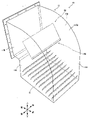
以下、実施の形態に係るダクト及び換気装置について図面を参照して説明する。本実施の形態に係るダクトは、図1に示す換気装置1のウェザーカバー10として構成されている。換気装置1は、外壁90に取付けられている。以下の説明では、外壁90が延びる天地方向を上下方向とする。また、外壁90の屋外側を前方、外壁90の屋内側を後方とする。さらに、外壁90の幅方向を左右方向とする。なお、図1、図3等では、各部材の厚みが誇張して描かれている。
A duct and a ventilation device according to embodiments will be described below with reference to the drawings. The duct according to this embodiment is configured as a
(換気装置1の構成)
図1に示すように、換気装置1は、ウェザーカバー10と、換気扇20と、ウェザーカバー10及び換気扇20が取り付けられた筒状の取付枠30と、を備える。換気装置1は、外壁90に取り付けられている。
(Configuration of ventilation device 1)
As shown in FIG. 1, the
換気扇20は、屋内に配置され、屋外の空気を吸気して屋内に引き込む。ウェザーカバー10は、屋外に配置され、雨水が取付枠30及び換気扇20を介して屋内に浸入することを防止する。取付枠30は、外壁90の開口91を通った状態で、不図示のL字鋼等の取付部材により、外壁90に取り付けられている。
The
ウェザーカバー10及び取付枠30は、換気扇20が吸気する屋外の空気である外気の流路を構成している。このため、ウェザーカバー10は、前記空気の流路の上流側に配置され、換気扇20は、前記空気の流路の下流側に配置されている。
The weather cover 10 and the
(ウェザーカバー10の構成)
図1及び図2に示すように、ウェザーカバー10は、換気扇20が吸気する屋外の空気の流路である曲がり流路Sを構成する両端開口の筒体であるカバー本体11と、カバー本体11の内部に配置された複数の上流側ブレード13及び下流側ブレード15と、を備える。曲がり流路Sは、その流れ方向SSの上流側に、上下方向に延びた直線状の上流部S1を備え、下流側に、前後方向に延びた直線状の下流部S2を備える。曲がり流路Sは、その流れ方向SSの中央部として、上流部S1と下流部S2との間に配置された、円弧状に90度曲がった中央部S3も有する。流れ方向SSは、曲がり流路Sの中心軸に沿った方向である。
(Configuration of weather cover 10)
As shown in FIGS. 1 and 2, the
カバー本体11は、断面四角で両端開口の筒体であり、その内部が曲がり流路Sとなるように、中央部が曲がっている。カバー本体11の一端の開口は、下方を向いており、屋外の空気が流入する上流側開口11Aとなっている。カバー本体11の他端の開口は、後方を向いており、換気扇20により吸気される下流側開口11Bとなっている。換気装置1の動作時、屋外の空気は、下方から上流側開口11Aを介して曲がり流路Sの上流部S1に流入し、中央部S3及び下流部S2を通り、下流側開口11Bから取付枠30に流出する。
The cover
カバー本体11は、曲がり流路Sを構成する4つの壁を含む。この4つの壁は、内側壁11Eと、外側壁11Fと、左側壁11Gと、右側壁11Hと、からなる。内側壁11Eは、曲がり流路Sの内側に配置されている。外側壁11Fは、曲がり流路Sの外側に配置され、内側壁11Eに対向している。外側壁11Fは、曲がり流路Sの中央部S3の外側縁を画定する中央壁11FAを備える。中央壁11FAは、円筒を周方向に4分の1にした形状であり、中心角が90度の円弧の断面を有する。左側壁11Gと右側壁11Hとは、左右方向に互いに対向している一対の側壁である。左側壁11Gは、曲がり流路Sの左側に配置され、内側壁11Eの左辺及び外側壁11Fの左辺に接続されている。右側壁11Hは、曲がり流路Sの右側に配置され、内側壁11Eの右辺及び外側壁11Fの右辺に接続されている。
The
複数の上流側ブレード13は、板状であり、上流側開口11Aの近傍に配置されている。より具体的に、複数の上流側ブレード13は、曲がり流路Sの上流部S1に配置されている。複数の上流側ブレード13は、内側壁11Eから外側壁11Fに向かう方向、より詳細には、前方に向かって下る斜め方向に並んで配置されている。上流側ブレード13の左端、右端は、溶接等により左側壁11G、右側壁11Hにそれぞれ固定されている。従って、上流側ブレード13は、一対の側壁11G及び11Hのうちの一方から他方まで延びている。上流側ブレード13は、左側壁11Gと右側壁11Hとの対向方向である左右方向に沿って延びている。
The plurality of
上流側ブレード13は、上下方向に対して傾いており、下流端の方が上流端よりも外側壁11F側つまり曲がり流路Sの外側に位置している。上流側ブレード13は、下流側の板状の第1部分13Aが上流側の板状の第2部分13Bよりも上下方向に対して大きな角度で傾くように折れ曲がっている。なお、複数の上流側ブレード13それぞれは、同形状であり、同じ角度で傾いている。
The
下流側ブレード15は、複数の上流側ブレード13よりも下流側に設けられている。下流側ブレード15は、内側壁11E及び外側壁11Fと離れた位置かつ曲がり流路Sの中央部S3に配置されている。下流側ブレード15の左端、右端は、溶接等により左側壁11G、右側壁11Hにそれぞれ固定されている。従って、下流側ブレード15は、一対の側壁11G及び11Hのうちの一方から他方まで延びている。下流側ブレード15は、左側壁11Gと右側壁11Hとの対向方向である左右方向に沿って延びている。
The
下流側ブレード15は、板状であり、上流側ブレード13と反対方向に傾いている。具体的に下流側ブレード15は、曲がり流路Sの中央部S3の湾曲した流れ方向の接線方向に沿うように、換言すると、下流側ブレード15の上端が下端よりも下流側開口11B側に位置するように上下方向に対して傾いている。また、下流側ブレード15は、下流側ブレード15の表面を上流側に延長した仮想面(図1の点線直線Z1参照)が、上流側ブレード13の下流側の第1部分13Aの表面(上流側を向いた表面)を下流側に延長した仮想面(図1の点線直線Z2参照)と略直交する向きで配置されている。さらに、下流側ブレード15は、その上流端が、複数の上流側ブレード13それぞれの下流側の第1部分13Aの表面(上流側を向いた表面)を下流側に延長した仮想面(図1の点線直線Z2参照)よりも下流側に位置するように配置されている。つまり、前記の仮想面は、下流側ブレード15の上流端の下流側を通っている。さらに、下流側ブレード15は、曲がり流路Sの中央部S3を区画している外側壁11Fの中央壁11FAと内側壁11Eの中央壁11EAとの間のほぼ中央に配置されている。
The
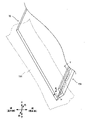
下流側ブレード15は、その上流端が略U字状に折り曲げられている。これにより、下流側ブレード15の上流端には、左右方向に沿って延び、曲がり流路Sの外側に突出した樋15Aが形成されている。図3に示すように、樋15Aは、左右方向の一端が、左側壁11Gと隙間Dを開けて設けられている。同様に、樋15Aの他端も、右側壁11Hと隙間を開けて設けられている。
The
(換気装置1の動作)
図1に戻り、換気扇20により、屋外の空気は、ウェザーカバー10の上流側開口11Aから吸い込まれる。これにより、ウェザーカバー10内に空気が流入する。ウェザーカバー10内に流入した空気は、下流側開口11Bから流出し、取付枠30を介して換気扇20に吸い込まれ、屋内に供給される。
(Operation of ventilator 1)
Returning to FIG. 1 , outdoor air is sucked from the
(換気装置1の動作時のウェザーカバー10内の空気及び雨粒の流れ)
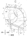
雨天時に換気扇20が動作して屋外の空気が屋内に引き込まれるときのウェザーカバー10内の様子について、図4を参照して説明する。なお、雨天時には、ウェザーカバー10に、空気とともに雨粒も浸入する。図4において、一点鎖線矢印は、空気の移動経路を示し、点線矢印は、雨粒U1及びU2の移動経路を示している。なお、以下での説明における外側は、曲がり流路Sにおける外側つまり外側壁11F側をいい、内側は、曲がり流路Sにおける内側つまり内側壁11E側をいう。
(Flow of air and raindrops in
The state inside the
換気扇20が動作すると、ウェザーカバー10内は下流側開口11Bを介して屋内側に吸気され、図4の矢印N1~N4に示すように、上流側開口11Aに、下方から空気が流入するとともに、当該空気に乗って雨粒U1及びU2も浸入する。
When the ventilating
上流側開口11Aにおける外側の領域からカバー本体11内に入り込んだ空気及び雨粒U1は、矢印N5及びN6に示すように、上下方向に対して傾いた上流側ブレード13の間を通り、上流側ブレード13により外側に案内され、外側壁11Fに当たる。外側壁11Fに当たった空気は、その後、外側壁11Fに沿ってウェザーカバー10内を移動して、取付枠30に流入する。他方、外側壁11Fに当たった雨粒U1は、外側壁11Fに付着し、外側壁11Fを伝って下方に移動し、最終的に、ウェザーカバー10の下方つまり外部に排出される。なお、雨粒U1の大きさによっては、複数の雨粒U1が集まって水滴に成長したあと、外側壁11Fを伝って下方に移動することもある。
Air and raindrops U1 that have entered the
上流側開口11Aにおける内側の領域からカバー本体11内に入り込んだ空気は、矢印N7に示すように、上流側ブレード13により案内され、外側に向かって移動する。ここで、下流側ブレード15の上流端は、上流側ブレード13の下流側の第1部分13Aの表面を下流側に延長した仮想面(図1の点線直線Z2参照)よりも下流側に位置するので、上流側ブレード13を通って外側に向かう空気は、下流側ブレード15の上流端の上流側を通って当該上流端の外側に流れる。この外側に向かう空気は、外側壁11Fには到達せずに、矢印N8に示すように、下流側ブレード15よりも外側の領域に移動して、下流側ブレード15と外側壁11Fの中央壁11FAとの間を通る。なお、上流側ブレード13を通った空気は、下流側ブレード15よりも内側かつ下流側の領域G1に発生する後述の渦により、この領域G1の方には向かわない。下流側ブレード15と外側壁11Fの中央壁11FAとの間を通る空気は、下流側ブレード15の外側に向く表面の近傍領域G2で生じる境界層剥離により、下流側ブレード15には沿わずに、矢印N9に示すように、下流側ブレード15の外側を大回りし、下流側開口11Bに向かう。
The air entering the
ここで、複数の上流側ブレード13により案内された空気は、領域G1の方に案内されないので、当該領域G1は、周囲の領域よりも低気圧となっている。このため、下流側ブレード15の外側を大回りして、下流側開口11B方向に移動する空気は、その大半が矢印N10のように、下流側開口11Bに流れるが、一部が、矢印N11のように、領域G1に流れ込み、領域G1に空気の渦が発生する。この渦は、図4の紙面に向かって反時計回りに回るので、上流側ブレード13に案内された空気が領域G1に向かうことを阻害する。このため、ウェザーカバー10では、上流側開口11Aに流入する空気のほとんどが、下流側ブレード15と外側壁11Fの中央壁11FAとの間を通って、下流側開口11Bに向かう。
Here, since the air guided by the plurality of
他方、上流側開口11Aにおける内側の領域からカバー本体11内に入り込んだ雨粒U2は、矢印N12に示すように、矢印N7で示す空気とともに、上流側ブレード13により案内され、外側に向かって移動する。複数の上流側ブレード13により案内された雨粒U2は、矢印N13に示すように、途中までは前記空気に乗って移動する。その後、雨粒U2は、当該空気が下流側ブレード15の外側を大回りするときに、当該雨粒U2に働く遠心力により、矢印N14に示すように、空気よりも外側にふられて、外側壁11Fの中央壁11FAに移動して付着する。中央壁11FAに付着した雨粒U2は、外側壁11Fを伝って下方に移動し、最終的に、ウェザーカバー10の外部に排出される。なお、雨粒U2の大きさによっては、複数の雨粒U2が集まって水滴に成長したあと、外側壁11Fを伝って下方に移動することもある。
On the other hand, the raindrops U2 that have entered the
さらに、この実施の形態では、下流側ブレード15の外側の面に雨粒が付着することがあるが、下流側ブレード15の上流端に樋15Aを設けたので、図3に示すように、下流側ブレード15に付着して下流側ブレード15を伝って落下する雨粒Y又は雨粒Yが集まった水滴は、樋15Aが受ける。さらに、樋15Aの一端と左側壁11Gとの間に隙間Dを設け、樋15Aの他端と右側壁11Hとの間にも隙間を設けたので、樋15Aに貯まった水は、当該隙間D等から左側壁11G又は右側壁11Hを伝って落ち、ウェザーカバー10の外部に排出される。
Furthermore, in this embodiment, although raindrops may adhere to the outer surface of the
(効果等)
本実施の形態のウェザーカバー10によれば、互いに反対方向に傾く、複数の上流側ブレード13及び下流側ブレード15を設けたので、下流側ブレード15の近傍において上記境界層剥離を生じさせることができ、ウェザーカバー10内に流入した空気を、下流側ブレード15と外側壁11Fとの間で大回りさせて、当該空気とともに浸入してきた雨粒を、空気の流れから分離し、外側壁11Fに当てることができる。従って、当該ウェザーカバー10によれば、雨粒が下流側開口11Bを通過して屋内に浸入し難くできる。特に、ウェザーカバー10では、領域G1の渦により、上流側開口11Aに流入する空気のほとんどを、下流側ブレード15と外側壁11Fの中央壁11FAとの間を通すので、ウェザーカバー10に流入する雨粒も領域G1を通らず、これにより、多くの雨粒を外側壁11Fに当てることができる。
(effects, etc.)
According to the
複数の上流側ブレード13を有するが下流側ブレード15を有さない比較例のウェザーカバーでも、0.7mm以上の径の大きい雨粒については、ある程度、外側壁11Fに当てることができるが、0.7mm未満の径の小さい雨粒は、そのほとんどが空気に乗って、下流側開口11Bを通過してしまう。この実施の形態のように下流側ブレード15を設けたウェザーカバー10では、前記の大回りにより、径の小さい雨粒をより多く外側壁11Fに当てることができ、雨粒がより下流側開口11Bを通過し難くなっている。さらに、当該ウェザーカバー10では、径の大きな雨粒もより多く、外側壁11Fに当てることができる。
Even in the weather cover of the comparative example that has a plurality of
さらに、下流側ブレード15は、その上流端が、複数の上流側ブレード13それぞれの下流側の第1部分13A(下流側の端部であればよい)の表面を下流側に延長した仮想面(図1の点線直線Z2参照)よりも下流側に位置するように配置されている。これにより、複数の上流側ブレード13により案内された空気を効果的に、上流側ブレード13と外側壁11Fとの間に誘導できる。さらに、下流側ブレード15は、下流側ブレード15の表面を上流側に延長した仮想面(図1の点線直線Z1参照)が、上流側ブレード13の下流側の第1部分13A(特に下流側の端部)の表面を下流側に延長した仮想面(図1の点線直線Z2参照)と略直交する向きで配置されている。なお、略直交としては、80度から100度が好ましい。これにより、上流側ブレード13により案内された空気が、下流側ブレード15の表面の垂線方向に近い角度で下流側ブレード15の下端近傍を通過するので、上記の境界層剥離の領域を大きくして、上記空気をより大回りにすることができ、雨粒の分離が生じやすくなる。さらに、これにより、複数の上流側ブレード13により案内された空気を効果的に、上流側ブレード13と外側壁11Fとの間に誘導できる。さらに、下流側ブレード15は、曲がり流路Sの中央部S3を区画している外側壁11Fの中央壁11FAと内側壁11Eの中央壁11EAとの間のほぼ中央に配置されている。これにより、ウェザーカバー10内の空気の流れのスムーズさもある程度確保できる。
Furthermore, the upstream end of the
さらに、この実施の形態では、樋15Aを設けたので、下流側ブレード15から雨粒等が直接下方に落下することを防止できる。下流側ブレード15から雨粒が直接落下すると、当該雨粒が、ウェザーカバー10に流入した空気にあおられてしまうことがあるが、樋15Aにより、これを防止できる。さらに、樋15Aの左右両端部と左側壁11G及び右側壁11Hとの間の隙間により、樋15Aに貯まった水を左側壁11G又は右側壁11Hを伝った状態で落とすことができ、これにより、前記水が空気によりあおられ難くすることができる。
Furthermore, in this embodiment, since the
(変形例)
上記実施の形態の構造は、ウェザーカバー10以外の、長い空気通路のうち曲がり流路を構成する部材としてのダクトに適用してもよい。この場合、上記カバー本体は、ダクト本体となる。換気扇は、他の吸気装置であってもよい。吸気装置としては、換気扇の他、シロッコファン、ポンプ等があげられる。上流側ブレード13及び下流側ブレード15は、平板状ではなく、湾曲していてもよい。ウェザーカバー10及び換気扇20は、取付枠30に他の部材を介して取付けられてもよい。
(Modification)
The structure of the above embodiment may be applied to a duct as a member forming a curved flow path in a long air passage other than the
1 換気装置、10 ウェザーカバー、11 カバー本体、11A 上流側開口、11B 下流側開口、11E 内側壁、11F 外側壁、11EA,11FA 中央壁、11G 左側壁、11H 右側壁、13 上流側ブレード、13A 下流側の第1部分、13B 上流側の第2部分、15 下流側ブレード、15A 樋、20 換気扇、30 取付枠、D 隙間、G1 領域、G2 近傍領域、S 曲がり流路、S1 上流部、S2 中央部、S3 下流部、SS 流れ方向、U1,U2,Y 雨粒。
1 ventilator, 10 weather cover, 11 cover body, 11A upstream opening, 11B downstream opening, 11E inner wall, 11F outer wall, 11EA, 11FA central wall, 11G left wall, 11H right wall, 13 upstream blade, 13A Downstream
Claims (5)
前記ダクト本体の内部の前記上流側開口の近傍に設けられた複数の上流側ブレードと、
前記ダクト本体の内部の前記複数の上流側ブレードの下流側に設けられた下流側ブレードと、を備え、
前記ダクト本体は、前記曲がり流路を構成する、内側壁と、当該内側壁に対向する外側壁と、互いに対向し前記内側壁と前記外側壁とに繋がった一対の側壁と、を備え、
前記複数の上流側ブレードそれぞれは、前記一対の側壁の一方から他方まで延び、かつ、下流端が上流端よりも前記外側壁の側に位置する向きに傾いており、
前記複数の上流側ブレードは、前記内側壁から前記外側壁に向かう方向に並んで配置されており、
前記下流側ブレードは、前記内側壁と前記外側壁と離れた位置かつ前記曲がり流路の流れ方向の中央部に配置され、前記一対の側壁の一方から他方まで延び、かつ、前記上流側ブレードと反対方向に傾いている、
ダクト。 a duct body having a rectangular cross-section and opening at both ends forming a curved flow path, wherein one end opening serves as a downstream opening through which air is sucked by an air intake device, and the other end opening serves as an upstream opening;
a plurality of upstream blades provided near the upstream opening inside the duct body;
a downstream blade provided downstream of the plurality of upstream blades inside the duct body;
The duct body includes an inner wall, an outer wall facing the inner wall, and a pair of side walls facing each other and connected to the inner wall and the outer wall, which constitute the curved flow path,
each of the plurality of upstream blades extends from one of the pair of side walls to the other, and is inclined such that the downstream end is located closer to the outer wall than the upstream end;
The plurality of upstream blades are arranged side by side in a direction from the inner wall toward the outer wall,
The downstream blade is disposed at a position apart from the inner wall and the outer wall and at a central portion in the flow direction of the curved flow path, extends from one side of the pair of side walls to the other, and is arranged with the upstream side blade. leaning in opposite directions,
duct.
前記上流側ブレードは板状で、
前記下流側ブレードは、上流端が、複数の前記上流側ブレードそれぞれの下流側の端部の表面を下流側に延長した仮想面よりも下流側に位置するように配置されている、
ダクト。 A duct according to claim 1,
The upstream blade is plate-shaped,
The downstream blade is arranged so that the upstream end is located downstream of a virtual plane extending downstream from the surface of the downstream end of each of the plurality of upstream blades.
duct.
前記上流側ブレードと前記下流側ブレードとは板状で、
当該下流側ブレードの表面を上流側に延長した仮想面が、前記上流側ブレードの下流側の端部の表面を下流側に延長した仮想面と略直交する向きで配置されている、
ダクト。 A duct according to claim 1 or 2,
The upstream blade and the downstream blade are plate-shaped,
A virtual plane obtained by extending the surface of the downstream blade to the upstream side is arranged in a direction substantially orthogonal to a virtual plane obtained by extending the surface of the downstream end of the upstream blade to the downstream side.
duct.
前記下流側ブレードの上流端に、前記下流側ブレードに付着した水を受ける樋が設けられている、
ダクト。 The duct according to any one of claims 1 to 3,
An upstream end of the downstream blade is provided with a gutter for receiving water adhering to the downstream blade.
duct.
換気扇と、
前記ウェザーカバー及び前記換気扇が取り付けられる取付枠と、
を備える換気装置。
a weather cover comprising the duct according to any one of claims 1 to 4;
ventilation fan and
a mounting frame to which the weather cover and the ventilation fan are mounted;
ventilation system.
Priority Applications (1)
| Application Number | Priority Date | Filing Date | Title |
|---|---|---|---|
| JP2020044412A JP7127079B2 (en) | 2020-03-13 | 2020-03-13 | Ducts and ventilators |
Applications Claiming Priority (1)
| Application Number | Priority Date | Filing Date | Title |
|---|---|---|---|
| JP2020044412A JP7127079B2 (en) | 2020-03-13 | 2020-03-13 | Ducts and ventilators |
Publications (2)
| Publication Number | Publication Date |
|---|---|
| JP2021143811A JP2021143811A (en) | 2021-09-24 |
| JP7127079B2 true JP7127079B2 (en) | 2022-08-29 |
Family
ID=77766346
Family Applications (1)
| Application Number | Title | Priority Date | Filing Date |
|---|---|---|---|
| JP2020044412A Active JP7127079B2 (en) | 2020-03-13 | 2020-03-13 | Ducts and ventilators |
Country Status (1)
| Country | Link |
|---|---|
| JP (1) | JP7127079B2 (en) |
Citations (3)
| Publication number | Priority date | Publication date | Assignee | Title |
|---|---|---|---|---|
| DE102008053510A1 (en) | 2008-10-28 | 2010-04-29 | Pötter Klima GmbH | Guide surface ventilator for use at e.g. flat roof for ventilation of interior of building, has side walls, guide plates, guide surfaces or regulating flaps possessing wing-like curved contour |
| JP2012112650A (en) | 2012-03-23 | 2012-06-14 | Mitsubishi Electric System & Service Co Ltd | Ventilating port member |
| JP2016156553A (en) | 2015-02-24 | 2016-09-01 | パナソニックIpマネジメント株式会社 | Ventilation device |
Family Cites Families (8)
| Publication number | Priority date | Publication date | Assignee | Title |
|---|---|---|---|---|
| JPS48107240U (en) * | 1972-03-14 | 1973-12-12 | ||
| JPH033645U (en) * | 1989-05-31 | 1991-01-16 | ||
| JP2872046B2 (en) * | 1994-07-18 | 1999-03-17 | 三菱電機株式会社 | Food equipment |
| JPH0933084A (en) * | 1995-07-17 | 1997-02-07 | Hazama Gumi Ltd | Air supply / exhaust duct opening structure |
| JP2930233B2 (en) * | 1996-05-31 | 1999-08-03 | 一男 林田 | Bend cap structure |
| JP2000193300A (en) * | 1998-12-24 | 2000-07-14 | Hayakawa Kogyo Kk | Ventilating opening frame for building |
| JP6332877B2 (en) * | 2016-05-19 | 2018-05-30 | 消音技研株式会社 | louver |
| JP2019158223A (en) * | 2018-03-13 | 2019-09-19 | パナソニックIpマネジメント株式会社 | Vent member |
-
2020
- 2020-03-13 JP JP2020044412A patent/JP7127079B2/en active Active
Patent Citations (3)
| Publication number | Priority date | Publication date | Assignee | Title |
|---|---|---|---|---|
| DE102008053510A1 (en) | 2008-10-28 | 2010-04-29 | Pötter Klima GmbH | Guide surface ventilator for use at e.g. flat roof for ventilation of interior of building, has side walls, guide plates, guide surfaces or regulating flaps possessing wing-like curved contour |
| JP2012112650A (en) | 2012-03-23 | 2012-06-14 | Mitsubishi Electric System & Service Co Ltd | Ventilating port member |
| JP2016156553A (en) | 2015-02-24 | 2016-09-01 | パナソニックIpマネジメント株式会社 | Ventilation device |
Also Published As
| Publication number | Publication date |
|---|---|
| JP2021143811A (en) | 2021-09-24 |
Similar Documents
| Publication | Publication Date | Title |
|---|---|---|
| US20150328979A1 (en) | Vehicle cooling structure | |
| JP5334928B2 (en) | Air conditioner indoor unit and air conditioner | |
| EP0763698B1 (en) | Cross flow blower | |
| KR101543603B1 (en) | waterproof ventilating opening cap | |
| JP2014118103A (en) | Cooling fan device | |
| JP3624808B2 (en) | Air conditioner decorative panel, air outlet unit, and air conditioner | |
| JP4976828B2 (en) | Air conditioner with air purification function | |
| JP3116874B2 (en) | Air outlet structure of air conditioner | |
| JP7127079B2 (en) | Ducts and ventilators | |
| EP3715730A1 (en) | Ceiling embedded air conditioner | |
| JPH10197045A (en) | Ventilation guide blade structure of air conditioner | |
| KR101233538B1 (en) | Cross-flow fan and air conditioner equipped with same | |
| JP4352982B2 (en) | Air conditioner outdoor unit | |
| JP3438323B2 (en) | Ceiling embedded air conditioner and horizontal blade structure of the device | |
| KR101440156B1 (en) | The outdoor unit of the air conditioner and its grill | |
| JP5591336B2 (en) | Air conditioner indoor unit and air conditioner | |
| JP4868014B2 (en) | Air conditioner outdoor unit | |
| JP3984598B2 (en) | Fan device | |
| CN109070945B (en) | Water separation in wheel covers | |
| JP2003185170A (en) | Air conditioner indoor unit | |
| JP2001301473A (en) | Engine room air vent structure | |
| WO2019180818A1 (en) | Indoor unit for air conditioner | |
| JPH10252689A (en) | Cross flow fan and air conditioner with cross flow fan | |
| KR101465513B1 (en) | Blower in vehicle for air circulating | |
| CN117677800A (en) | Air conditioning unit exhaust vent |
Legal Events
| Date | Code | Title | Description |
|---|---|---|---|
| A621 | Written request for application examination |
Free format text: JAPANESE INTERMEDIATE CODE: A621 Effective date: 20201118 |
|
| A131 | Notification of reasons for refusal |
Free format text: JAPANESE INTERMEDIATE CODE: A131 Effective date: 20220125 |
|
| TRDD | Decision of grant or rejection written | ||
| A01 | Written decision to grant a patent or to grant a registration (utility model) |
Free format text: JAPANESE INTERMEDIATE CODE: A01 Effective date: 20220726 |
|
| A61 | First payment of annual fees (during grant procedure) |
Free format text: JAPANESE INTERMEDIATE CODE: A61 Effective date: 20220817 |
|
| R150 | Certificate of patent or registration of utility model |
Ref document number: 7127079 Country of ref document: JP Free format text: JAPANESE INTERMEDIATE CODE: R150 |
|
| R250 | Receipt of annual fees |
Free format text: JAPANESE INTERMEDIATE CODE: R250 |