JP7127052B2 - Systems and methods for monitoring atmospheric particulate matter - Google Patents
Systems and methods for monitoring atmospheric particulate matter Download PDFInfo
- Publication number
- JP7127052B2 JP7127052B2 JP2019554492A JP2019554492A JP7127052B2 JP 7127052 B2 JP7127052 B2 JP 7127052B2 JP 2019554492 A JP2019554492 A JP 2019554492A JP 2019554492 A JP2019554492 A JP 2019554492A JP 7127052 B2 JP7127052 B2 JP 7127052B2
- Authority
- JP
- Japan
- Prior art keywords
- particles
- substrate
- trapped
- sensor
- air
- Prior art date
- Legal status (The legal status is an assumption and is not a legal conclusion. Google has not performed a legal analysis and makes no representation as to the accuracy of the status listed.)
- Active
Links
Images


Classifications
-
- G—PHYSICS
- G01—MEASURING; TESTING
- G01N—INVESTIGATING OR ANALYSING MATERIALS BY DETERMINING THEIR CHEMICAL OR PHYSICAL PROPERTIES
- G01N15/00—Investigating characteristics of particles; Investigating permeability, pore-volume or surface-area of porous materials
- G01N15/02—Investigating particle size or size distribution
- G01N15/0205—Investigating particle size or size distribution by optical means
- G01N15/0227—Investigating particle size or size distribution by optical means using imaging; using holography
-
- G—PHYSICS
- G01—MEASURING; TESTING
- G01N—INVESTIGATING OR ANALYSING MATERIALS BY DETERMINING THEIR CHEMICAL OR PHYSICAL PROPERTIES
- G01N1/00—Sampling; Preparing specimens for investigation
- G01N1/02—Devices for withdrawing samples
- G01N1/22—Devices for withdrawing samples in the gaseous state
- G01N1/2202—Devices for withdrawing samples in the gaseous state involving separation of sample components during sampling
- G01N1/2205—Devices for withdrawing samples in the gaseous state involving separation of sample components during sampling with filters
-
- G—PHYSICS
- G01—MEASURING; TESTING
- G01N—INVESTIGATING OR ANALYSING MATERIALS BY DETERMINING THEIR CHEMICAL OR PHYSICAL PROPERTIES
- G01N1/00—Sampling; Preparing specimens for investigation
- G01N1/02—Devices for withdrawing samples
- G01N1/22—Devices for withdrawing samples in the gaseous state
- G01N1/2273—Atmospheric sampling
-
- G—PHYSICS
- G01—MEASURING; TESTING
- G01N—INVESTIGATING OR ANALYSING MATERIALS BY DETERMINING THEIR CHEMICAL OR PHYSICAL PROPERTIES
- G01N1/00—Sampling; Preparing specimens for investigation
- G01N1/28—Preparing specimens for investigation including physical details of (bio-)chemical methods covered elsewhere, e.g. G01N33/50, C12Q
- G01N1/2813—Producing thin layers of samples on a substrate, e.g. smearing, spinning-on
-
- G—PHYSICS
- G01—MEASURING; TESTING
- G01N—INVESTIGATING OR ANALYSING MATERIALS BY DETERMINING THEIR CHEMICAL OR PHYSICAL PROPERTIES
- G01N15/00—Investigating characteristics of particles; Investigating permeability, pore-volume or surface-area of porous materials
- G01N15/02—Investigating particle size or size distribution
- G01N15/0205—Investigating particle size or size distribution by optical means
- G01N15/0211—Investigating a scatter or diffraction pattern
-
- G—PHYSICS
- G01—MEASURING; TESTING
- G01N—INVESTIGATING OR ANALYSING MATERIALS BY DETERMINING THEIR CHEMICAL OR PHYSICAL PROPERTIES
- G01N15/00—Investigating characteristics of particles; Investigating permeability, pore-volume or surface-area of porous materials
- G01N15/06—Investigating concentration of particle suspensions
- G01N15/0606—Investigating concentration of particle suspensions by collecting particles on a support
- G01N15/0618—Investigating concentration of particle suspensions by collecting particles on a support of the filter type
- G01N15/0625—Optical scan of the deposits
-
- G—PHYSICS
- G01—MEASURING; TESTING
- G01N—INVESTIGATING OR ANALYSING MATERIALS BY DETERMINING THEIR CHEMICAL OR PHYSICAL PROPERTIES
- G01N15/00—Investigating characteristics of particles; Investigating permeability, pore-volume or surface-area of porous materials
- G01N15/06—Investigating concentration of particle suspensions
- G01N15/0606—Investigating concentration of particle suspensions by collecting particles on a support
- G01N15/0637—Moving support
-
- G—PHYSICS
- G01—MEASURING; TESTING
- G01N—INVESTIGATING OR ANALYSING MATERIALS BY DETERMINING THEIR CHEMICAL OR PHYSICAL PROPERTIES
- G01N15/00—Investigating characteristics of particles; Investigating permeability, pore-volume or surface-area of porous materials
- G01N15/06—Investigating concentration of particle suspensions
- G01N15/0656—Investigating concentration of particle suspensions using electric, e.g. electrostatic methods or magnetic methods
-
- G—PHYSICS
- G01—MEASURING; TESTING
- G01N—INVESTIGATING OR ANALYSING MATERIALS BY DETERMINING THEIR CHEMICAL OR PHYSICAL PROPERTIES
- G01N15/00—Investigating characteristics of particles; Investigating permeability, pore-volume or surface-area of porous materials
- G01N15/10—Investigating individual particles
- G01N15/14—Optical investigation techniques, e.g. flow cytometry
- G01N15/1429—Signal processing
- G01N15/1433—Signal processing using image recognition
-
- G—PHYSICS
- G01—MEASURING; TESTING
- G01N—INVESTIGATING OR ANALYSING MATERIALS BY DETERMINING THEIR CHEMICAL OR PHYSICAL PROPERTIES
- G01N21/00—Investigating or analysing materials by the use of optical means, i.e. using sub-millimetre waves, infrared, visible or ultraviolet light
- G01N21/84—Systems specially adapted for particular applications
- G01N21/88—Investigating the presence of flaws or contamination
- G01N21/94—Investigating contamination, e.g. dust
-
- G—PHYSICS
- G01—MEASURING; TESTING
- G01N—INVESTIGATING OR ANALYSING MATERIALS BY DETERMINING THEIR CHEMICAL OR PHYSICAL PROPERTIES
- G01N1/00—Sampling; Preparing specimens for investigation
- G01N1/28—Preparing specimens for investigation including physical details of (bio-)chemical methods covered elsewhere, e.g. G01N33/50, C12Q
- G01N1/2813—Producing thin layers of samples on a substrate, e.g. smearing, spinning-on
- G01N2001/2833—Collecting samples on a sticky, tacky, adhesive surface
-
- G—PHYSICS
- G01—MEASURING; TESTING
- G01N—INVESTIGATING OR ANALYSING MATERIALS BY DETERMINING THEIR CHEMICAL OR PHYSICAL PROPERTIES
- G01N15/00—Investigating characteristics of particles; Investigating permeability, pore-volume or surface-area of porous materials
- G01N2015/0042—Investigating dispersion of solids
- G01N2015/0046—Investigating dispersion of solids in gas, e.g. smoke
-
- G—PHYSICS
- G01—MEASURING; TESTING
- G01N—INVESTIGATING OR ANALYSING MATERIALS BY DETERMINING THEIR CHEMICAL OR PHYSICAL PROPERTIES
- G01N15/00—Investigating characteristics of particles; Investigating permeability, pore-volume or surface-area of porous materials
- G01N15/02—Investigating particle size or size distribution
- G01N2015/0294—Particle shape
-
- G—PHYSICS
- G01—MEASURING; TESTING
- G01N—INVESTIGATING OR ANALYSING MATERIALS BY DETERMINING THEIR CHEMICAL OR PHYSICAL PROPERTIES
- G01N15/00—Investigating characteristics of particles; Investigating permeability, pore-volume or surface-area of porous materials
- G01N2015/03—Electro-optical investigation of a plurality of particles, the analyser being characterised by the optical arrangement
-
- G—PHYSICS
- G01—MEASURING; TESTING
- G01N—INVESTIGATING OR ANALYSING MATERIALS BY DETERMINING THEIR CHEMICAL OR PHYSICAL PROPERTIES
- G01N15/00—Investigating characteristics of particles; Investigating permeability, pore-volume or surface-area of porous materials
- G01N15/10—Investigating individual particles
- G01N2015/1029—Particle size
-
- G—PHYSICS
- G01—MEASURING; TESTING
- G01N—INVESTIGATING OR ANALYSING MATERIALS BY DETERMINING THEIR CHEMICAL OR PHYSICAL PROPERTIES
- G01N15/00—Investigating characteristics of particles; Investigating permeability, pore-volume or surface-area of porous materials
- G01N15/10—Investigating individual particles
- G01N2015/103—Particle shape
-
- G—PHYSICS
- G01—MEASURING; TESTING
- G01N—INVESTIGATING OR ANALYSING MATERIALS BY DETERMINING THEIR CHEMICAL OR PHYSICAL PROPERTIES
- G01N15/00—Investigating characteristics of particles; Investigating permeability, pore-volume or surface-area of porous materials
- G01N15/10—Investigating individual particles
- G01N15/14—Optical investigation techniques, e.g. flow cytometry
- G01N2015/1493—Particle size
-
- G—PHYSICS
- G01—MEASURING; TESTING
- G01N—INVESTIGATING OR ANALYSING MATERIALS BY DETERMINING THEIR CHEMICAL OR PHYSICAL PROPERTIES
- G01N15/00—Investigating characteristics of particles; Investigating permeability, pore-volume or surface-area of porous materials
- G01N15/10—Investigating individual particles
- G01N15/14—Optical investigation techniques, e.g. flow cytometry
- G01N2015/1497—Particle shape
-
- G—PHYSICS
- G01—MEASURING; TESTING
- G01N—INVESTIGATING OR ANALYSING MATERIALS BY DETERMINING THEIR CHEMICAL OR PHYSICAL PROPERTIES
- G01N21/00—Investigating or analysing materials by the use of optical means, i.e. using sub-millimetre waves, infrared, visible or ultraviolet light
- G01N21/84—Systems specially adapted for particular applications
- G01N21/85—Investigating moving fluids or granular solids
- G01N2021/8578—Gaseous flow
- G01N2021/8585—Gaseous flow using porous sheets, e.g. for separating aerosols
Landscapes
- Chemical & Material Sciences (AREA)
- Health & Medical Sciences (AREA)
- Life Sciences & Earth Sciences (AREA)
- Biochemistry (AREA)
- General Physics & Mathematics (AREA)
- Pathology (AREA)
- Immunology (AREA)
- Analytical Chemistry (AREA)
- Physics & Mathematics (AREA)
- General Health & Medical Sciences (AREA)
- Dispersion Chemistry (AREA)
- Engineering & Computer Science (AREA)
- Biomedical Technology (AREA)
- Molecular Biology (AREA)
- Signal Processing (AREA)
- Investigating Or Analysing Materials By Optical Means (AREA)
- Sampling And Sample Adjustment (AREA)
- Computer Vision & Pattern Recognition (AREA)
Description
〔関連出願の相互参照〕
本出願は、「Low-Cost Air Particulate Monitor Based On Particle Capture And Imaging」のタイトルで、2016年12月19日に出願された米国仮特許出願第62/436,030号の優先権および利益を主張し、この内容は、参照により全体として本明細書に組み込まれる。
[Cross reference to related applications]
This application claims priority to and benefit from U.S. Provisional Patent Application No. 62/436,030, entitled "Low-Cost Air Particulate Monitor Based On Particle Capture And Imaging," filed December 19, 2016 , the contents of which are incorporated herein by reference in their entirety.
〔分野〕
本出願は、大気粒子状物質を監視するための、さらに具体的には、粒子を捕捉し、捕捉された粒子を読み取り(reading)、捕捉された粒子から収集した情報に基づいて解析を実行するための、システムおよび方法に関する。
[field]
The present application is directed to monitoring atmospheric particulate matter, and more specifically trapping particles, reading the trapped particles, and performing analysis based on information gleaned from the trapped particles. for systems and methods.
〔背景〕
環境衛生は、ますます重要になっている世界的問題のままである。例えば、大気汚染は、例えば、地球の放射収支、雲の形成、地球温暖化および視程に影響を及ぼす環境効果を有することが知られている。大気汚染のこれらの環境影響は、特に目、鼻、のど、肺、心臓、および妊娠結果に関する、人間の健康にも影響を及ぼす。大気汚染の悪影響を緩和するため、多くの国が、汚染物質を規制するために法律を制定している。その結果、さまざまな存在が、大気汚染を監視し、必要に応じて措置を講じることを義務付けられるか、またはそのように動機付けされてきた。この目的で、例えば、製造業者、建設業者、および都市などの存在が、より清潔で地球にやさしい環境を達成することを目的として、より環境にやさしい機械類、車、飛行機、建物、工場、インフラストラクチャーなどをますます開発または利用してきた。
〔background〕
Environmental health remains an increasingly important global issue. For example, air pollution is known to have environmental effects affecting, for example, the Earth's radiation budget, cloud formation, global warming and visibility. These environmental effects of air pollution also affect human health, especially with respect to eyes, nose, throat, lungs, heart, and pregnancy outcomes. In order to mitigate the adverse effects of air pollution, many countries have enacted legislation to regulate pollutants. As a result, various entities have been mandated or motivated to monitor air pollution and take action when necessary. To this end, entities such as manufacturers, builders, and cities, for example, are developing greener machinery, cars, planes, buildings, factories, and infrastructure, with the aim of achieving a cleaner, greener environment. Structures and the like have been increasingly developed or utilized.
これらの汚染制御規制および環境にやさしい構想の恩恵は、大気汚染を監視し、その影響を緩和するため、必要に応じて予防的または救済的措置を取ることを必要とする。実際、これらの規制および構想の恩恵は、大気汚染監視の頻度、広さ、および質と直接関連する。言い換えれば、より多い頻度でより多くのモニターを配備することにより、より強力で、より正確な汚染知識および情報がもたらされ、これらは、予防的および救済的なツールおよび技術を強化することができる。 The benefits of these pollution control regulations and environmentally friendly initiatives require the monitoring of air pollution and taking preventive or remedial action as necessary to mitigate its effects. In fact, the benefits of these regulations and initiatives are directly related to the frequency, extent, and quality of air pollution monitoring. In other words, deploying more monitors with greater frequency will result in stronger and more accurate contamination knowledge and information, which can enhance preventive and remedial tools and techniques. can.
現在、フィルターを使用して粒子を収集し、それらの質量を測定することができる、微粒子監視テクノロジーが存在する。他の微粒子監視テクノロジーは、迅速に通過する空気中の粒子にレーザー光を向ける。したがって、これらの既存のテクノロジーは、例えば、テクノロジーの感知限界、または粒子が分析され得る時間の短さにより、粒子について得ることができる情報の量が限られている。さらに、従来の微粒子監視システムは、大きく、高価であり、機能するために著しい量の電力を必要とし、例えばスマートシティで、大量に配備するには非実用的となる。 Currently, particle monitoring technology exists that uses filters to collect particles and measure their mass. Other particle surveillance technologies aim laser light at rapidly passing airborne particles. These existing technologies are therefore limited in the amount of information that can be obtained about the particles, for example due to the technology's sensing limits or the short time in which the particles can be analyzed. Additionally, conventional particle monitoring systems are large, expensive, and require significant amounts of electrical power to function, making them impractical for mass deployment, eg, in smart cities.
したがって、粒子を空気から捕捉し、捕捉されている間に粒子の分析を可能にすることができる、大気粒子状物質監視を提供するシステムおよび方法が必要とされている。捕捉された粒子が、光学センサまたは画像センサなどのセンサによって読み取られることができる必要もある。さらに、よりきれいであるかまたは粒子を含まない基板が粒子の捕捉のために提供され得るように、粒子が捕捉される基板を補充する必要がある。さらに、リアルタイムデータを考慮に入れ、感知性能を最適化するために、監視が動的に調節可能である必要がある。さらになお、粒子状物質監視を、広く、安く、かつ非侵入的に利用可能にする必要がある。 Accordingly, there is a need for systems and methods that provide atmospheric particulate matter monitoring that can capture particles from the air and enable analysis of the particles while they are captured. There is also a need for trapped particles to be able to be read by a sensor, such as an optical sensor or an image sensor. Further, there is a need to replenish the substrate on which particles are captured so that cleaner or particle-free substrates can be provided for particle capture. Furthermore, monitoring needs to be dynamically adjustable to take into account real-time data and optimize sensing performance. Furthermore, there is a need to make particulate matter monitoring widely, cheaply, and non-intrusively available.
〔概要〕
例えば空気中の、粒子状物質(PM)を監視するためのシステムおよび方法が、本明細書に記載される。より具体的には、空気から粒子を捕捉し、捕捉されている間に、粒子に対して感知動作を実行する、PM監視システムおよび方法が本明細書に記載される。粒子は、電気集塵および機械的捕獲器(mechanical captors)、ツールおよび/または技術のうちの1つ、またはその組み合わせを用いて、捕捉され得る。本明細書に記載するように、電気集塵は、(1)導電性基板を1つの電荷で帯電させること、および(2)基板の電荷と反対の別の電荷で、収集された空気中の粒子を帯電させること、によって達成され得る。粒子は、電極によって帯電されて電荷担体を生成し、粒子を帯電させて逆荷電基板の方向にそらすことができ、粒子は分析のために付着したままとすることができる。機械的ツールおよび技術が、同様に、またはさらに使用されて、粒子を捕捉することができる。例えば、基板として機能するフィルターまたは繊維群で構成される、ろ過システム。フィルターおよび/または繊維は、空気がその中を流れるときに粒子を横取りするように構成される。空気の流れおよび粒子が収集される空気の体積は、空気ポンプまたは同様のシステムを用いて、制御され得る。
〔Overview〕
Systems and methods for monitoring particulate matter (PM), such as in air, are described herein. More specifically, PM monitoring systems and methods are described herein that capture particles from the air and perform sensing operations on the particles while they are captured. Particles can be captured using one or a combination of electrostatic precipitators and mechanical captors, tools and/or techniques. As described herein, electrostatic precipitation involves (1) charging a conductive substrate with one charge and (2) collecting charging the particles. The particles are charged by the electrodes to generate charge carriers, which can be charged and deflected towards the oppositely charged substrate, where they can remain attached for analysis. Mechanical tools and techniques can also or additionally be used to trap particles. For example, a filtration system consisting of a filter or group of fibers acting as a substrate. The filters and/or fibers are configured to intercept particles as air flows through them. The flow of air and the volume of air from which particles are collected can be controlled using an air pump or similar system.
基板上に収集された粒子は、次に、1つ以上のセンサによって、撮像されるか、または別様に感知され得る。光学センサおよび画像センサ、例えばカメラを含む、さまざまなセンサを使用することができる。センサによる撮像は、光を基板に向け、これにより、基板上に捕捉された粒子が光を散乱させることによって実行され得る。散乱光は、センサによって検出され、情報を入手し、かつ/または捕捉された粒子を撮像するのに使用され得る。入射または反射光が散乱光に干渉するのを避けるため、照明光源によって基板に向けられた光は、視射角で提供され得る。照明光源を視射角で位置づけることに加えて、またはその代わりに、基板は、導波管として機能するように構成され得る。粒子の撮像または他の感知は、さらなる分析を実行するのに使用され得る。例えば、粒子に関する特徴またはデータ、例えばそれらのサイズ、位置、形状、および分布が、検出または算出され、次に、他の情報、例えば粒子または汚染物質のタイプまたは供給源を導き出すのに使用され得る。 Particles collected on the substrate may then be imaged or otherwise sensed by one or more sensors. A variety of sensors can be used, including optical sensors and image sensors such as cameras. Imaging by the sensor may be performed by directing light onto the substrate such that particles trapped on the substrate scatter the light. The scattered light can be detected by a sensor and used to obtain information and/or image the trapped particles. Light directed at the substrate by the illumination source may be provided at a glancing angle to avoid incident or reflected light from interfering with the scattered light. Additionally or alternatively to positioning the illumination source at a glancing angle, the substrate may be configured to act as a waveguide. Imaging or other sensing of particles can be used to perform further analysis. For example, features or data about the particles, such as their size, position, shape, and distribution, can be detected or calculated and then used to derive other information, such as the type or source of the particles or contaminants. .
粒子が捕捉される基板は、基板またはその表面をクリーニングするかまたは交換することによって、補充され得る。基板またはその表面を補充することは、例えば新しい粒子を捕捉し分析し得る、きれいなまたはよりきれいな表面を提供するために、実行され得る。表面の補充は、静電および/または機械的クリーナー、ツール、および技術を用いて実行され得る。例えば、静電補充は、基板上に捕捉された荷電粒子に逆の電荷を印加し、それらを、基板から切り離すか、または分離させることによって、達成される。械的ツールおよび技術は、粒子を基板もしくはその表面からからバラバラにするかまたは分離させる、ブラシ、加熱、および振動のうちの1つ以上の使用を含み得る。場合によっては、テープが、粒子を捕捉する基板または基板の表面として分配され使用され得る。よって、基板またはその表面を補充するため、テープのロールが、粒子を捕捉し得るテープの新しいきれいなセクションを提供するため、前進させられ得る。 The substrate on which the particles are trapped can be replenished by cleaning or replacing the substrate or its surface. Replenishment of the substrate or its surface can be performed, for example, to provide a cleaner or cleaner surface on which new particles can be captured and analyzed. Surface replenishment can be performed using electrostatic and/or mechanical cleaners, tools, and techniques. For example, electrostatic replenishment is accomplished by applying an opposite charge to charged particles trapped on the substrate, causing them to detach or separate from the substrate. Mechanical tools and techniques may include the use of one or more of brushes, heat, and vibration to break up or separate particles from the substrate or its surface. In some cases, a tape can be dispensed and used as a substrate or surface of a substrate to trap particles. Thus, to replenish the substrate or its surface, the roll of tape can be advanced to provide a new clean section of tape that can trap particles.
本明細書に記載するPM監視の態様および特徴は、リアルタイムで動的に調節され得る。動的調節は、監視プロセスが、意図する目的およびゴールに従って最適に実行されることを確実にする。この目的で、実行時間中に収集される情報は、粒子が捕捉される空気の、収集されている体積;撮像仕様(例えば、頻度、波長、ダイナミックレンジ);構成要素(例えば、照明光源、基板、センサ)の位置づけ;基板を補充するタイプおよび時間;ならびに、本明細書に記載され、当業者に既知である他のものなどの態様および特徴を調節する必要性または要望を判断するために分析され使用され得る。 Aspects and features of PM monitoring described herein can be dynamically adjusted in real time. Dynamic adjustment ensures that the monitoring process is performing optimally according to intended objectives and goals. To this end, the information collected during runtime includes the volume of air in which the particles are trapped; imaging specifications (e.g., frequency, wavelength, dynamic range); components (e.g., illumination source, substrate); type and time to replenish the substrate; and other aspects and features described herein and known to those of skill in the art. can be used.
粒子状物質を監視するための例示的な一方法では、粒子は1つ以上の基板上で空気から捕捉される。捕捉は、静電および機械的捕獲器、ツール、および/または技術のうちの1つ以上を用いて実行される。1つ以上の感知動作が、捕捉された粒子に対して実行される。捕捉された粒子は、1つ以上の感知動作の結果に基づいて分析され得る。粒子が基板上に捕捉されると、粒子は、1つ以上の感知動作を粒子に対して実行するのに十分長い期間にわたって維持され得る基板に対する制御位置にくる。 In one exemplary method for monitoring particulate matter, particles are captured from the air on one or more substrates. Capturing is performed using one or more of electrostatic and mechanical traps, tools, and/or techniques. One or more sensing operations are performed on the trapped particles. Trapped particles may be analyzed based on the results of one or more sensing operations. Once a particle is trapped on the substrate, the particle is in a controlled position relative to the substrate that can be maintained for a period of time long enough to perform one or more sensing operations on the particle.
いくつかの実施形態では、1つ以上の基板は導電性である。粒子を1つ以上の基板上に捕捉するために、1つ以上の基板のうちの少なくとも1つは、第1の電荷で帯電され、粒子は、第2の電荷で帯電される。第2の電荷は、第1の電荷の反対である。粒子を第2の電荷で帯電させることにより、粒子は、1つ以上の基板に向かって、またその上へとそれる。 In some embodiments, one or more substrates are electrically conductive. At least one of the one or more substrates is charged with a first charge and the particles are charged with a second charge to trap the particles on the one or more substrates. The second charge is the opposite of the first charge. Charging the particles with a second charge causes the particles to deflect toward and onto one or more substrates.
いくつかの実施形態では、1つ以上の基板は、フィルターを含む。粒子を1つ以上の基板上に捕捉するために、空気は、1つ以上の基板のフィルターを通って、またはこの上を流れることができ、それによって、空気中の粒子を、フィルターのうちの1つ以上によって捕捉させる。 In some embodiments, one or more substrates include filters. Air can flow through or over the filters of one or more substrates to trap the particles on one or more substrates, thereby removing particles in the air from Get caught by one or more.
いくつかの実施形態では、1つ以上の基板は、可動のテープの1つ以上の部分によって形成される。可動のテープは、1つ以上の基板上での粒子の捕捉と同時に粒子が捕捉されない、他の部分を含む。 In some embodiments, the one or more substrates are formed by one or more pieces of movable tape. The moveable tape includes other portions where particles are not captured simultaneously with particle capture on one or more substrates.
いくつかの実施形態では、粒子を1つ以上の基板上に捕捉することは、空気ポンプを用いて1つ以上の基板に向かう空気の流れを促進することを含む。 In some embodiments, trapping particles on one or more substrates includes promoting air flow toward one or more substrates with an air pump.
いくつかの実施形態では、1つ以上の基板は、基板の本体から離れた方を向く、改質表面を含む。粒子は、1つ以上の基板の改質表面に付着することによって1つ以上の基板上に捕捉される。 In some embodiments, one or more substrates include a modified surface facing away from the body of the substrate. Particles are trapped on one or more substrates by adhering to the modified surface of one or more substrates.
いくつかの実施形態では、粒子が捕捉される1つ以上の基板の少なくとも一部は、粒子の捕捉が可動のテープの別の部分で実行されるように可動のテープを前進させることによって補充される。 In some embodiments, at least a portion of the one or more substrates on which particles are captured is replenished by advancing the moveable tape such that particle capture is performed on another portion of the moveable tape. be.
いくつかの実施形態では、粒子が捕捉される1つ以上の基板の少なくとも1つの表面がクリーニングされる。 In some embodiments, at least one surface of one or more substrates on which particles are trapped is cleaned.
いくつかの実施形態では、少なくとも1つの表面のクリーニングは、機械的クリーナーおよび静電クリーナーのうちの1つ以上を用いて実行される。 In some embodiments, cleaning the at least one surface is performed using one or more of a mechanical cleaner and an electrostatic cleaner.
いくつかの実施形態では、少なくとも1つの表面を、静電クリーナーを用いてクリーニングするため、捕捉された粒子は、第1の電荷に等しい第3の電荷で帯電される。捕捉された粒子を第3の電荷で帯電させることにより、粒子は、1つ以上の基板から離れて分離する。 In some embodiments, at least one surface is cleaned with an electrostatic cleaner so that the trapped particles are charged with a third charge equal to the first charge. Charging the trapped particles with a third charge separates the particles away from the one or more substrates.
いくつかの実施形態では、1つ以上の感知動作は、光学感知、音響感知、電磁感知、および誘電感知のうちの1つ以上を実行するように構成された1つ以上のセンサによって実行される。 In some embodiments, the one or more sensing operations are performed by one or more sensors configured to perform one or more of optical sensing, acoustic sensing, electromagnetic sensing, and dielectric sensing. .
いくつかの実施形態では、1つ以上のセンサは、最適な感知を実行するように構成され、1つ以上のセンサはカメラを含む。 In some embodiments, the one or more sensors are configured to perform optimal sensing, and the one or more sensors include cameras.
いくつかの実施形態では、1つ以上の感知動作は光学感知を含む。1つ以上の感知動作のうちの光学感知を実行するため、1つ以上の基板は照らされ、1つ以上の基板上に捕捉された粒子によって散乱する散乱光が検出される。 In some embodiments, the one or more sensing operations include optical sensing. To perform optical sensing of the one or more sensing operations, one or more substrates are illuminated and scattered light scattered by particles trapped on the one or more substrates is detected.
いくつかの実施形態では、照らすことは、視射角で1つ以上の基板に向けられた光を用いて実行される。 In some embodiments, illuminating is performed with light directed at one or more substrates at a glancing angle.
いくつかの実施形態では、1つ以上の基板上に捕捉された粒子を撮像することは、捕捉された粒子によって散乱する散乱光に少なくとも部分的に基づく。 In some embodiments, imaging particles trapped on one or more substrates is based at least in part on scattered light scattered by the trapped particles.
いくつかの実施形態では、1つ以上の感知動作の結果は、1つ以上の基板上に捕捉された粒子の1つ以上の画像を含む。捕捉された粒子を分析することは、捕捉された粒子の画像から粒子に対応する粒子データを識別することを含む。 In some embodiments, results of one or more sensing operations include one or more images of particles captured on one or more substrates. Analyzing the captured particles includes identifying particle data corresponding to the particles from the images of the captured particles.
いくつかの実施形態では、捕捉された粒子を分析することは、汚染または粒子状物質情報を、粒子データに基づいて計算することを含む。 In some embodiments, analyzing the trapped particles includes calculating contamination or particulate matter information based on the particle data.
いくつかの実施形態では、動的調節は、粒子を捕捉するステップ、1つ以上の感知動作を実行するステップ、および捕捉された粒子を分析するステップのうちの1つ以上の態様に対する調節を含む。 In some embodiments, dynamic adjustment includes adjustment to aspects of one or more of capturing particles, performing one or more sensing operations, and analyzing captured particles. .
いくつかの実施形態では、動的調節は、(1)粒子が捕捉される空気の体積を調節することと、(2)粒子の捕捉、1つ以上の感知動作の実行、または捕捉された粒子の分析を実行するタイミングを調節することと、3)1つ以上の基板またはその表面を補充またはクリーニングすることと、のうちの少なくとも1つを含む。 In some embodiments, dynamic adjustment includes (1) adjusting the volume of air in which particles are trapped; and (2) trapping particles, performing one or more sensing operations, or and/or 3) replenishing or cleaning the one or more substrates or surfaces thereof.
粒子状物質を監視するためのシステムの例示的な一実施形態では、基板が、電気集塵およびろ過ベースの捕捉のうちの1つ以上を用いて基板上で空気からの粒子を捕捉する。センサが、捕捉された粒子に対して1つ以上の感知動作を実行する。少なくとも1つのプロセッサが、センサに、捕捉された粒子に対して1つ以上の感知動作を実行させる。基板、センサ、および少なくとも1つのプロセッサは、通信可能に連結される。粒子が基板上に捕捉されると、粒子は、1つ以上の感知動作を粒子に対して実行するのに十分長い期間にわたって維持され得る基板に対する制御位置にくる。 In one exemplary embodiment of a system for monitoring particulate matter, a substrate traps particles from the air on the substrate using one or more of electrostatic precipitator and filtration-based trapping. A sensor performs one or more sensing operations on the trapped particles. At least one processor causes the sensor to perform one or more sensing operations on the trapped particles. The substrate, sensor, and at least one processor are communicatively coupled. Once a particle is trapped on the substrate, the particle is in a controlled position relative to the substrate that can be maintained for a period of time long enough to perform one or more sensing operations on the particle.
いくつかの実施形態では、基板は導電性材料を含む。粒子を基板上に捕捉するために、基板は、第1の電荷で帯電され、粒子は、空気中で、第2の電荷で帯電され、第2の電荷は第1の電荷の反対である。粒子を第2の電荷で帯電させることにより、粒子が、基板に向かって、またこの上へとそれる。 In some embodiments, the substrate comprises a conductive material. To trap the particles on the substrate, the substrate is charged with a first charge and the particles in air are charged with a second charge, the second charge being opposite to the first charge. Charging the particles with a second charge causes the particles to deflect toward and over the substrate.
いくつかの実施形態では、基板はフィルターを含む。粒子を基板上に捕捉するために、空気は、基板のフィルターを通って、またはこの上を流れることができ、それによって、空気中の粒子を、フィルターのうちの1つ以上によって捕捉させる。 In some embodiments, the substrate includes filters. To trap particles on the substrate, air can flow through or over the filters of the substrate, thereby causing particles in the air to be trapped by one or more of the filters.
いくつかの実施形態では、基板は、可動のテープの1つ以上の部分によって形成され、可動のテープは、1つ以上の基板上での粒子の捕捉と同時に粒子が捕捉されない、他の部分を含む。 In some embodiments, the substrate is formed by one or more portions of moveable tape, and the moveable tape includes other portions where particles are not captured simultaneously with particle capture on one or more substrates. include.
いくつかの実施形態では、空気ポンプが、空気の流れを増減させるように動作可能である。粒子を基板上に捕捉するために、空気ポンプは、基板に向かう、粒子を含有する空気の流れを増減させる。 In some embodiments, an air pump is operable to increase or decrease the flow of air. To trap the particles on the substrate, the air pump increases or decreases the flow of particle-laden air toward the substrate.
いくつかの実施形態では、基板は、基板の本体から離れた方を向く、改質表面を含む。粒子は、基板の改質表面に付着することによって基板上に捕捉される。 In some embodiments, the substrate includes a modified surface facing away from the body of the substrate. Particles are trapped on the substrate by adhering to the modified surface of the substrate.
いくつかの実施形態では、粒子が捕捉されるテープの少なくとも一部は、粒子の捕捉が可動のテープの別の部分で実行されるように可動のテープを前進させることによって補充される。 In some embodiments, at least a portion of the tape on which particles are captured is replenished by advancing the moveable tape such that particle capture is performed on another portion of the moveable tape.
いくつかの実施形態では、粒子が捕捉される基板の少なくとも1つの表面は、クリーニングされる。 In some embodiments, at least one surface of the substrate on which particles are trapped is cleaned.
いくつかの実施形態では、基板の少なくとも1つの表面のクリーニングは、機械的クリーナーおよび静電クリーナーのうちの1つ以上を用いて実行される。 In some embodiments, cleaning at least one surface of the substrate is performed using one or more of a mechanical cleaner and an electrostatic cleaner.
いくつかの実施形態では、基板の少なくとも1つの表面を、静電クリーナーを用いてクリーニングするため、捕捉された粒子は、第1の電荷に等しい第3の電荷で帯電される。捕捉された粒子を第3の電荷で帯電させることにより、粒子は、基板から離れて分離する。 In some embodiments, at least one surface of the substrate is cleaned with an electrostatic cleaner so that the trapped particles are charged with a third charge equal to the first charge. Charging the trapped particles with a third charge separates the particles away from the substrate.
いくつかの実施形態では、センサは、光学感知、音響感知、電磁感知、および誘電感知のうちの1つ以上を実行する。 In some embodiments, the sensor performs one or more of optical sensing, acoustic sensing, electromagnetic sensing, and dielectric sensing.
いくつかの実施形態では、カメラを含むセンサは、最適な感知をを用いて1つ以上の感知動作を実行するように構成される。 In some embodiments, sensors, including cameras, are configured to perform one or more sensing operations with optimal sensing.
いくつかの実施形態では、1つ以上の感知動作のうちの最適な感知を実行することは、照明光源に基板を照らさせることと、基板上に捕捉された粒子によって散乱する散乱光を、センサによって検出することと、を含む。 In some embodiments, performing optimal sensing of the one or more sensing operations includes having an illumination source illuminate the substrate and scattering light scattered by particles trapped on the substrate to the sensor. and detecting by.
いくつかの実施形態では、基板を照らすために、照明光源は、視射角で基板に光を向ける。 In some embodiments, to illuminate the substrate, the illumination source directs light onto the substrate at a glancing angle.
いくつかの実施形態では、センサは、捕捉された粒子によって散乱する散乱光に少なくとも部分的に基づいて、捕捉された粒子を撮像する。 In some embodiments, the sensor images the trapped particles based at least in part on scattered light scattered by the trapped particles.
いくつかの実施形態では、捕捉された粒子は、1つ以上の感知動作の結果に基づいて分析される。 In some embodiments, trapped particles are analyzed based on results of one or more sensing operations.
いくつかの実施形態では、1つ以上の感知動作の結果は、基板上に捕捉される粒子の1つ以上の画像を含む。捕捉された粒子を分析するために、粒子に対応する粒子データが、捕捉された粒子の画像から識別される。 In some embodiments, results of one or more sensing operations include one or more images of particles captured on the substrate. To analyze the trapped particles, particle data corresponding to the particles are identified from the images of the trapped particles.
いくつかの実施形態では、捕捉された粒子を分析することは、汚染または粒子状物質情報を、粒子データに基づいて計算することを含む。 In some embodiments, analyzing the trapped particles includes calculating contamination or particulate matter information based on the particle data.
いくつかの実施形態では、システムまたはその動作の態様が、動的に調節される。 In some embodiments, aspects of the system or its operation are dynamically adjusted.
いくつかの実施形態では、動的調節は、(1)粒子が捕捉される空気の体積を調節することと、(2)空気からの粒子の捕捉、または1つ以上の感知動作のタイミングを調節することと、3)基板またはその表面を補充またはクリーニングすることと、のうちの少なくとも1つを含む。 In some embodiments, the dynamic adjustment consists of (1) adjusting the volume of air in which particles are trapped and (2) adjusting the timing of the trapping of particles from the air or one or more sensing operations. and 3) replenishing or cleaning the substrate or its surface.
いくつかの実施形態では、センサは撮像デバイスである。 In some embodiments the sensor is an imaging device.
いくつかの実施形態では、撮像デバイスは、相補型金属酸化膜半導体(CMOS)ベースの画像センサまたは電荷結合素子(CCD)ベースの画像センサのうちの1つである。 In some embodiments, the imaging device is one of a complementary metal-oxide-semiconductor (CMOS)-based image sensor or a charge-coupled device (CCD)-based image sensor.
いくつかの実施形態では、基板は、光を透過させるように動作可能な、パターン化された導電性層またはパターン化された導電性フィルムを含む。 In some embodiments, the substrate comprises a patterned conductive layer or patterned conductive film operable to transmit light.
いくつかの実施形態では、パターン化された導電性フィルムは、酸化インジウムスズ(ITO)である。 In some embodiments, the patterned conductive film is indium tin oxide (ITO).
いくつかの実施形態では、基板は、照明光の導波管を形成する。 In some embodiments, the substrate forms a waveguide for illumination light.
いくつかの実施形態では、導波管は、二酸化ケイ素を含む機械要素を含む。 In some embodiments, the waveguide includes mechanical elements that include silicon dioxide.
いくつかの実施形態では、散乱光は、複数の波長の光で散乱する。 In some embodiments, the scattered light scatters at multiple wavelengths of light.
いくつかの実施形態では、照明光源は、近紫外線(UV)または可視光である。 In some embodiments, the illumination source is near ultraviolet (UV) or visible light.
いくつかの実施形態では、基板および/またはセンサは、互いに対して移動する。 In some embodiments, the substrate and/or sensor move relative to each other.
いくつかの実施形態では、基板は可撓性である。 In some embodiments, the substrate is flexible.
粒子状物質を監視するためのシステムの例示的な一実施形態では、粒子捕捉サブシステムが、基板を含む。粒子捕捉サブシステムは、基板上に空気から粒子を捕捉するように動作可能である。感知サブシステムが、基板上に捕捉された粒子に対して感知動作を実行するための1つ以上のセンサを含む。補充サブシステムが、基板または基板の表面を、その上に捕捉された粒子のすべてまたは一部を除去することによって、補充する。解析サブシステムが、粒子に対して実行された感知動作の結果に基づいて分析動作を実行する。 In one exemplary embodiment of the system for monitoring particulate matter, the particle capture subsystem includes a substrate. The particle trapping subsystem is operable to trap particles from the air onto the substrate. A sensing subsystem includes one or more sensors for performing sensing operations on particles trapped on the substrate. A replenishment subsystem replenishes the substrate or surface of the substrate by removing all or some of the particles trapped thereon. An analysis subsystem performs analysis operations based on the results of the sensing operations performed on the particles.
本出願は、添付図面と共に理解される、以下の詳細な説明から、さらに十分に理解されるであろう。 The present application will be more fully understood from the following detailed description taken in conjunction with the accompanying drawings.
〔詳細な説明〕
特定の例示的な実施形態を説明して、本明細書に開示するシステムおよび方法の構造、機能、製造、および使用の原理の全体的な理解を提供する。これらの実施形態の1つ以上の実施例が、添付図面に示されている。当業者は、本明細書に具体的に記載し、添付図面に例示するシステムおよび方法が、非限定的な例示的な実施形態であること、また、本開示の範囲が、特許請求の範囲によってのみ定められることを、理解するであろう。例示的な一実施形態に関連して例示または記載される特徴は、他の実施形態の特徴と組み合わせることができる。このような改変および変形は、本開示の範囲内に含まれることが意図されている。本開示では、さまざまな実施形態の同様の符号の構成要素は一般的に、それらの構成要素が同様の性質のものであり、かつ/または同様の目的に役立つ場合、同様の特徴を有する。当業者は、本開示を考慮すれば、さまざまな図面にわたる同様の符号の構成要素が類似しているさまざまな場合を理解するであろう。さらに、いくつかの場合、当業者に理解されるか、別様に既知であり、かつ/または本開示で提供される、さまざまな用語は、互換的に使用されている。非限定的な実施例として、捕捉するおよび収集する、デバイスおよびシステム、光および照明などの用語は、本明細書では互換的に使用され得る。
[Detailed description]
Certain exemplary embodiments are described to provide a general understanding of the principles of construction, function, manufacture, and use of the systems and methods disclosed herein. One or more examples of these embodiments are illustrated in the accompanying drawings. Those skilled in the art will appreciate that the systems and methods specifically described herein and illustrated in the accompanying drawings are non-limiting exemplary embodiments and that the scope of the present disclosure is defined by the claims. You will understand that only Features illustrated or described in connection with one exemplary embodiment may be combined with features of other embodiments. Such modifications and variations are intended to be included within the scope of this disclosure. In this disclosure, like-numbered components of various embodiments generally have similar features if those components are of a similar nature and/or serve a similar purpose. Those skilled in the art will appreciate the various instances in which like-numbered components across the various drawings are similar, given this disclosure. Moreover, in some cases various terms understood or otherwise known to those of ordinary skill in the art and/or provided in this disclosure are used interchangeably. As non-limiting examples, terms such as capturing and collecting, devices and systems, light and illumination may be used interchangeably herein.
本明細書で提供されるシステムおよび方法は、基板上で粒子を捕捉し、粒子が捕捉されている間に感知動作を実行することによって、大気粒子状物質(PM)を監視するためのものである。記載されるシステムおよび方法は、本明細書に記載され、当業者に既知であるさまざまな感知動作を実行し得るが、1つの感知動作は、カメラなどの画像センサを用いた、捕捉された粒子の撮像である。さらに、記載されるシステムおよび方法は、大気粒子状物質の監視で使用されるように本明細書に記載されているが、これらは、水を含む他の流体環境を監視するように容易に適応され得る。この目的で、PMセンサまたはシステムは、捕捉されている間に撮像するために空気から粒子を捕捉する。粒子は、粒子を基板に向かって駆動するか、または引き寄せるために、静電および/または機械的ツールおよび技術(互換的に「捕獲器」と呼ばれる)、例えば高性能微粒子捕集効率(HEPA)フィルターで使用される電気集塵またはろ過機構を用いて、捕捉され得る。本明細書に記載するように、さまざまなツールおよび技術が使用され得、PMシステムの目的(例えば、粒子が空気から捕捉されているか、または流体から捕捉されているか)に基づき得る。小さい粒子は、表面改質がなくても大部分の表面にくっつく傾向があるが、基板表面は、いくつかの実施形態では、付着を高めるか、または制御するために、改質され得ることを理解されたい。例えば、本明細書に記載するように、接着層(例えば、接着グルーの層)、または分子層が、提供され得る。さらに、いくつかの実施形態では、ガラス基板が、シランの化学的性質(chemistry)を用いて、改質されて、基板の表面を、親水性、疎水性、親油性、疎油性などにすることができる。他の基板は、マイクロスケールまたはナノスケールでテクスチャを付けられて、クリーニングを容易にするか、または別様にデバイスの機能を高めることができる。 The systems and methods provided herein are for monitoring atmospheric particulate matter (PM) by trapping particles on a substrate and performing sensing operations while the particles are trapped. be. Although the systems and methods described can perform a variety of sensing operations described herein and known to those skilled in the art, one sensing operation is to detect captured particles using an image sensor such as a camera. This is an image of Furthermore, although the systems and methods described are described herein for use in monitoring atmospheric particulate matter, they are readily adaptable to monitor other fluid environments, including water. can be To this end, PM sensors or systems capture particles from the air for imaging while they are being captured. Particles are collected using electrostatic and/or mechanical tools and techniques (interchangeably referred to as "trappers"), such as High Efficiency Particulate Efficiency (HEPA), to drive or attract the particles toward the substrate. It can be captured using electrostatic precipitators or filtration mechanisms used in filters. Various tools and techniques may be used, as described herein, and may be based on the objectives of the PM system (eg, whether particles are being captured from the air or from the fluid). Small particles tend to stick to most surfaces without surface modification, but substrate surfaces can be modified to enhance or control adhesion in some embodiments. be understood. For example, an adhesive layer (eg, a layer of adhesive glue), or molecular layer can be provided as described herein. Further, in some embodiments, the glass substrate is modified using silane chemistry to make the surface of the substrate hydrophilic, hydrophobic, oleophilic, oleophobic, etc. can be done. Other substrates can be textured at the microscale or nanoscale to facilitate cleaning or otherwise enhance device functionality.
いくつかの実施形態では、静電粒子捕捉ツールおよび技術は、電気集塵および/または電気集塵器の使用を含み得、これにより、空気からの粒子は、粒子および基板をそれぞれ反対の電荷で帯電させることによって導電性基板に向かって、また導電性基板へとそれる。すなわち、それぞれ反対の電荷により、粒子は基板まで駆動され、そこで捕捉される。機械的粒子捕捉ツールおよび技術は、ろ過システムの使用を含み得る。ろ過システムは、基板として機能するフィルターおよび/または繊維のマットで構成され得る。フィルターおよび/または繊維は、空気がその中を通って流れると、空気から粒子を横取りするように構成される。粒子が捕捉される空気の流れまたは空気の体積は、空気ポンプ、空気注入もしくは排気システム、または当業者に既知である空気を動かす任意の他の方法によって、制御され得る。いくつかの実施形態では、例えば風による、空気の自然な動きは、空気を受動的にサンプリングするのに使用され得る。PMシステムは、通過する空気の量を測定するためにエアフローセンサを含むか、またはこれに通信可能に連結され得る。 In some embodiments, electrostatic particle capture tools and techniques may include the use of electrostatic precipitators and/or electrostatic precipitators, whereby particles from the air trap particles and substrates with opposite charges, respectively. It deflects toward and away from the conductive substrate by charging. That is, the opposite charges drive the particles to the substrate and trap them there. Mechanical particle capture tools and techniques can include the use of filtration systems. The filtration system may consist of a filter and/or a fiber mat that acts as a substrate. The filters and/or fibers are configured to intercept particles from the air as it flows therethrough. The flow or volume of air in which particles are trapped can be controlled by an air pump, an air injection or exhaust system, or any other method of moving air known to those skilled in the art. In some embodiments, the natural movement of air, eg, due to wind, can be used to passively sample the air. The PM system may include or be communicatively coupled to an airflow sensor to measure the amount of air passing therethrough.
さらに本明細書に記載するPMセンサに関連して、捕捉された粒子は、画像センサなどのセンサを使用して感知されるか、または読み取られ得る。当然、他のタイプの感知が、センサによって提供され得、これには、それぞれ設定されたセンサを用いた、光学感知、音響感知、電磁感知、誘電感知、および当業者に既知の他のものが含まれる。画像センサは、カメラ、および粒子が捕捉される基板に光を向ける照明光源を含み得る。光は、紫外線(UV)(例えば、近紫外線)光、または発光ダイオード(LED)からの光であってよい。照明光源は、光を基板に向け、基板上で捕捉された粒子が光を散乱させるように、位置づけられ得る。いくつかの実施形態では、(例えば、反射によって生じる)画像センサの直接照明を避けるため、光は、視射角で向けられ得、かつ/または、基板は、導波管として構成され得る。次に、散乱光は、カメラによって検出され、これに基づいて、粒子の画像を得ることができる。デジタル画像または感知結果は、センサによって、または、クラウドコンピューティングシステムもしくは管理システムなどの、関連デバイスもしくは通信可能に連結されたデバイスによって、記憶され得る。 Further in connection with the PM sensors described herein, trapped particles can be sensed or read using a sensor such as an image sensor. Of course, other types of sensing may be provided by the sensors, including optical sensing, acoustic sensing, electromagnetic sensing, dielectric sensing, and others known to those skilled in the art, using respective configured sensors. included. The image sensor may include a camera and an illumination source that directs light onto the substrate where the particles are captured. The light may be ultraviolet (UV) (eg, near-UV) light, or light from a light emitting diode (LED). The illumination source may be positioned such that it directs light onto the substrate and particles trapped on the substrate scatter the light. In some embodiments, light may be directed at a glancing angle and/or the substrate may be configured as a waveguide to avoid direct illumination of the image sensor (eg, caused by reflection). The scattered light is then detected by a camera and based on this an image of the particle can be obtained. Digital images or sensing results may be stored by the sensor or by an associated or communicatively linked device, such as a cloud computing system or management system.
センサによって得られた画像または他の感知もしくは読取結果は、大気汚染分析など、それに関する分析を実行するために使用され得る。このような分析は、粒子情報(例えば、サイズ、位置、分布)を検出もしくは算出すること、または、それから他のデータ(例えば、タイプ、供給源)を導き出すこと、を含み得る。算出された情報または導き出されたデータのタイプは、いくつかあるものの中で特に、PMセンサの目的またはターゲットに応じて、大きく変化し得る。例えば、屋内に(例えば、建物内に)配されたPMセンサは、屋外に(例えば、交通信号上に)位置づけられたPMとは異なるタイプの粒子データ(例えば、汚染物質のタイプ、供給源など)を検出するように、プログラムされ得る。感知された粒子の分析は、PMセンサによって、および/またはPMセンサの解析システムによって、ローカルに実行され得ることを、理解されたい。分析は、データ(例えば、粒子感知結果、履歴データ、閾値、モデル、ルール)を記憶し、かつ/または例えば、サービスおよびアプリケーションへのアクセスを提供することができる、関連するか、または通信可能に連結されたシステム、例えばクラウドコンピューティングシステムもしくは管理システムによって、またはこれと共に、実行され得る。分析の結果は、さらなるアクション、例えば準備、治療、または抑制イベントを判断および/またはトリガーするように記憶されるか、またはさらに処理され得る。空気の監視、またはその一部は、PMセンサの目的およびその特徴に基づいて最適または好適とみなされる場合、連続して、または断続的に、実行され得る。例えば、粒子収集は、連続して実行され得、撮像ならびに他の検知および分析は、間隔を置いて(例えば毎時)実行される。 Images or other sensing or readings obtained by the sensor may be used to perform analysis thereon, such as air pollution analysis. Such analysis may include detecting or calculating particle information (eg, size, location, distribution) or deriving other data therefrom (eg, type, source). The type of calculated information or derived data can vary greatly depending on, among other things, the purpose or target of the PM sensor. For example, a PM sensor placed indoors (e.g., in a building) may have a different type of particle data (e.g., pollutant type, source, etc.) than a PM placed outdoors (e.g., on a traffic light). ) can be programmed to detect It should be appreciated that the analysis of sensed particles may be performed locally by the PM sensor and/or by the PM sensor's analysis system. Analytics may store data (e.g., particle sensing results, historical data, thresholds, models, rules) and/or provide access to services and applications, for example, associated or communicable It can be performed by or in conjunction with a linked system, such as a cloud computing system or management system. The results of the analysis may be stored or further processed to determine and/or trigger further actions, such as preparatory, therapeutic, or inhibitory events. Air monitoring, or portions thereof, may be performed continuously or intermittently, as deemed optimal or suitable based on the PM sensor's purpose and its characteristics. For example, particle collection can be performed continuously, with imaging and other detection and analysis performed at intervals (eg, hourly).
粒子が収集される基板は、補充されて、例えば、基板上での粒子の継続した蓄積が、PMセンサを無用にしないことを確実にすることができる。この目的で、基板は、粒子が捕捉される基板の表面をクリーニングすることによって、および/または粒子が捕捉される表面の一部を交換することによって、補充され得る。基板または基板表面のクリーニングは、静電および/または機械的ツールおよび技術の使用を含み得る。静電クリーニングは、逆の電荷(reverse charge)(例えば、基板の電荷に等しい電荷)を捕捉された粒子に印加し、これらを基板から切り離すか、または係合解除させることを含む。機械的クリーニングアプローチは、粒子を基板から切り離すか、または係合解除させるために、ブラシの使用、振動、加熱などを含む。 The substrate from which particles are collected can be replenished, for example, to ensure that continued accumulation of particles on the substrate does not render the PM sensor useless. For this purpose, the substrate can be replenished by cleaning the surface of the substrate on which the particles are trapped and/or by replacing a portion of the surface on which the particles are trapped. Cleaning a substrate or substrate surface can involve the use of electrostatic and/or mechanical tools and techniques. Electrostatic cleaning involves applying a reverse charge (eg, a charge equal to that of the substrate) to the trapped particles to break or disengage them from the substrate. Mechanical cleaning approaches include the use of brushes, vibration, heating, etc. to detach or disengage the particles from the substrate.
クリーニングに加え、またはその代わりに、基板または基板の表面は、交換されて、それによって、分析のために粒子が捕捉され得る、粒子を含まないエリアを提供することができる。この目的で、PMセンサは、テープのロールを含むテープケースを含み得る。テープのロールにおけるテープは、基板自体として機能でき、または、基板の上に配され得る。テープのあるセクションは、露出され、粒子が蓄積し得るエリアとして使用される。所望の時間に、例えば多数の粒子がテープのそのセクション上に収集されたときに、テープケースは、テープを前進させて、テープの新しい(例えば、粒子を含まない)セクションを、粒子が蓄積されるエリアとして、露出させ得る。粒子が蓄積しているテープのセクションは、次の試験または分析のため、後で物理的に保管され得る。基板または基板表面の補充は、光学的(optical)または好適とみなされる任意の時間に実行され得、これには、スケジュールに対応する時間または動的に決定された時間が含まれる。 In addition to or in lieu of cleaning, the substrate or surface of the substrate can be exchanged thereby providing a particle-free area in which particles can be captured for analysis. To this end, the PM sensor may include a tape case containing rolls of tape. The tape in the roll of tape can serve as the substrate itself or can be placed on top of the substrate. Certain sections of the tape are exposed and used as areas where particles can accumulate. At a desired time, e.g., when a large number of particles have been collected on that section of the tape, the tape case advances the tape to remove a new (e.g., particle-free) section of tape from which particles have accumulated. can be exposed as an area Sections of the tape with accumulated particles can be physically stored later for subsequent testing or analysis. Replenishment of the substrate or substrate surface can be performed optically or at any time deemed suitable, including times corresponding to a schedule or dynamically determined times.
本明細書に記載されるPMセンサは、大気粒子状物質の動的な監視に備える。この目的で、監視プロセス全体にわたり、PMセンサは、動的調節が、識別された要件またはオプションによってトリガーされているかどうかを、リアルタイムで識別し得る。動的調節(および他のトリガーされたアクションまたはプロセス)が、識別された要件(例えば、ハードルール、閾値)によって、または、識別されたオプション(例えば、ソフトルール、ユーザの希望の手動入力)によって、トリガーされ得ることを、理解されたい。動的調節の例としては、粒子を捕捉するために収集された空気の体積、構成要素(例えば、センサ、照明光源)の位置づけ、撮像仕様(例えば、波長)、補充、ダイナミックレンジ、および本明細書に記載され当業者に既知である他のものに関するものが含まれる。このように、PM監視システムは、最適な粒子感知および分析を提供し、その機能性を最適化することができる。 The PM sensors described herein provide for dynamic monitoring of atmospheric particulate matter. To this end, throughout the monitoring process, PM sensors may identify in real-time whether dynamic adjustments are being triggered by identified requirements or options. Dynamic adjustments (and other triggered actions or processes) are by identified requirements (e.g., hard rules, thresholds) or by identified options (e.g., soft rules, user desired manual input) , can be triggered. Examples of dynamic adjustments include the volume of air collected to trap particles, positioning of components (eg, sensors, illumination sources), imaging specifications (eg, wavelength), replenishment, dynamic range, and the and others known to those of ordinary skill in the art. In this way, the PM monitoring system can provide optimal particle sensing and analysis and optimize its functionality.
大気粒子状物質監視エコシステム
図1は、例えば本明細書に記載するような粒子状物質(PM)センサを用いて、大気粒子状物質を監視するためのエコシステム100の例示的な実施形態を示す。エコシステム100は、さまざまなシステム、センサ、物体、ネットワーク、インフラストラクチャーなどを含み、これらは、いくつかの実施形態では、大気粒子状物質データを収集および監視し、監視に基づいてアクション、イベント、機能などをトリガーするのに使用され得る。大気粒子状物質監視エコシステム100は、任意の数およびタイプの相互接続されたシステム、センサ、物体、ネットワーク、インフラストラクチャーなどを含み得、そのうち、図1に示すものは、例示的な実施例として役立つことを、理解されたい。例えば、エコシステム100は、モノのインターネット(IoT)、公共もしくは私的ネットワーク、または相互接続されたデバイスの任意の同様のセットを指すことができる。示された例示的な粒子状物質監視エコシステム100では、データが、本明細書に記載するものおよび当業者に既知の他のものなどの基準またはプロトコルを用いて、有線または無線通信を介して、伝送され得ることも、理解されたい。
Air Particulate Matter Monitoring Ecosystem FIG. 1 illustrates an exemplary embodiment of an
図1に示すように、エコシステム100は、スマート環境101を含み、これは、ネットワーク103を介して、クラウドコンピューティングシステム105および管理システム107に接続されている。スマート環境101は、データを収集および/もしくは通信し得るハードウェア(例えばセンサ)もしくは機能性を備えているか、またはこれを有する、任意の物体、構造体、またはエリアであってよい。例えば、スマート環境101は、車および飛行機などの物体、建物もしくは住宅などの構造体、または街路、近所、もしくは都市などのエリアであってよいか、またはこれらを含み得る。いくつかの実施形態では、スマート環境101は、大気粒子状物質の監視が望まれるか、好ましいか、または必要とされる、物体、構造体、および/またはエリアである。大気粒子状物質の監視が実行される場合の非限定的な例としては、とりわけ、環境インパクトテスト、会計検査、およびコンプライアンス管理、ならびに緊急応答補助のためのものが含まれる。
As shown in FIG. 1,
前述したとおり、スマート環境101は、さまざまなデバイスのうちの1つ以上を含んでよく、これは、電子機器、ソフトウェア、センサ、アクチュエータ、および/またはそれらがデータを収集しかつ/または互いと通信する(例えばデータの送信および/もしくは受信)のを可能にする接続性が埋め込まれているか、またはこれらを含む。デバイスという用語は、システム、サブシステム、および当業者に既知の他の電子機器もしくはコンピューティングコンポーネントを指すのに使用され、それらはすべて、本明細書で互換的に使用され得ることを、理解されたい。さらに、当業者に既知のとおり、スマート環境101のデバイスは、伝統的にはデータの収集も通信もできないが、それを行うための機能性(例えば、センサ、接続性)を備えているか、またはそれと共に構成されている、物体、アイテム、または物であってよいか、またはそれらを指し得ることを、理解されたい。
As previously mentioned,
図1に示すように、スマート環境101は、デバイス101d-1、101d-2、・・・、および101d-n(集合的に本明細書では「101d」または「デバイス101d」と呼ぶ)を含み得る。スマート環境101がスマートシティである例示的な一実施形態では、デバイス101dは、例えば、センサ、都市のライト、建物、交通信号、カメラ、アラームなどの固定された物体、または電車、自動車、モバイルデバイス、コンピュータなどの受動物体であってよいか、またはこれらを含み得る。デバイス101dはそれぞれ、一群の構成要素(例えば、さまざまなセンサを有する建物)を指すことができ、または、一群の構成要素のうちの特定の1つ(例えば、建物内の単一のセンサ)を指すことができると、理解されたい。
As shown in FIG. 1,
スマート環境101における一種のデバイスはPMセンサであり、以下、PMセンサ101d-1と呼ばれるが、スマート環境101は、任意の数のPMセンサを有し得る。PMセンサ101d-1は、例えばその意図する目的および/またはスマート環境のタイプに応じて、さまざまな方法で装備または配備され得る。例えば、PMセンサ101d-1は、建物内部の空気の質を監視するためにスマートビルディング内の屋内で、または、都市の屋外の空気の質を監視するためにスマートシティで、使用され得る。いくつかの実施形態では、PMセンサ101d-1は、汚染物質について測定されている空気または空気流への十分なおよび/または最適な曝露を有し得るように、位置づけられる。PMセンサ101d-1およびその機能性は、以下でさらに詳細に説明する。
One type of device in
前述したとおり、スマート環境101は、ネットワーク103を介してクラウドコンピューティングシステム105および管理システム107に接続されて、例えば集中型の監視および機能性(例えば、サービス、ストレージ)を提供する。単一のクラウドコンピューティングシステム105および単一の管理システム107が図1に示されているが、エコシステム100は、任意の数のクラウドコンピューティングシステム105および/または管理システム107を含み得ることを、理解されたい。クラウドコンピューティングシステム105は、パブリッククラウドもしくはプライベートクラウドであってよいか、またはそれらを含み得る。
As previously mentioned,
ネットワーク103は、1つ以上のネットワークを含み得ることを、理解されたい。ネットワーク103の非限定的な例は、インターネット、プライベートエリアネットワーク(PAN)、ローカルエリアネットワーク(LAN)、広域ネットワーク(WAN)、メトロポリタン・エリア・ネットワーク(MAN)、企業のプライベートネットワーク(EPN)、仮想プライベートネットワーク(VPN)などを含む。ネットワーク103を介した通信、および/またはエコシステム100のシステム間(例えば、デバイスとデバイス、デバイスとクラウド)の本明細書に記載する他の通信は、}Wi-Fi、ブルートゥース、ブルートゥース・ロー・エナジー(BLE)、およびセルラー(例えば、3G、4G、LTE)もしくは衛星通信サービスを含む、当業者に既知のさまざまな有線および無線技術、基準、およびプロトコルを用いて実行され得ることを理解されたい。
It should be appreciated that
クラウドコンピューティングシステム(本明細書では「クラウド」とも呼ばれる)105は、共有のコンピューティングデバイスと、スマート環境101および/または管理システム107のものなどのシステムおよびデバイスにアクセス可能なデータとから構成された、インフラストラクチャーを指す。共有のコンピューティング資源は、ネットワーク、サーバー、ストレージ、アプリケーション、およびサービスを含み得る。当業者は、任意のタイプのデータおよびデバイスをクラウド105に含め得ることを理解するであろう。クラウド105内のコンテンツの非限定的な一例は、例えばPMセンサ101d-1から収集された、大気粒子状物質データを含む。クラウド105内のアプリケーションおよびサービスは、PM監視アプリケーションなどを含み得、これは、本明細書に記載し、当業者に既知であるような、大気粒子状物質データの監視、解析および/または他の処理を提供するのに使用され得る。スマート環境101がスマートシティである例示的なシナリオでは、PMセンサから収集された大気粒子状物質データは、例えば、クラウド105内に保管され得、そこから、例えば汚染の潜在的毒性レベルまたは汚染増加の予期せぬパターンを導き出すか、または識別するために、(例えば、PM監視アプリケーションによって)使用され得る。大気粒子状物質データを監視し、分析し、かつ/または処理するために単独で、または組み合わせて使用され得る、サービスおよびアプリケーション(例えばPM監視アプリケーション)は、クラウド105、管理システム107、および/または、本明細書には記載しない他のシステムおよび/もしくは存在(例えば、研究機関のシステム)に、記憶され、かつ/またはそれらによって提供され得ることを、理解されたい。いくつかの実施形態では、クラウド105は、データを分析し、フィードバック、指示などを出力するためにPM監視アプリケーションによって使用され得る、モデルおよびルールを記憶することができる。さらに、いくつかの実施形態では、クラウド105は、当業者には既知であるように、大気粒子状物質データの分析中に人工知能ツールおよび技術を含むか、または利用することができる。
A cloud computing system (also referred to herein as a “cloud”) 105 consists of shared computing devices and data accessible to systems and devices such as those of
管理システム107は、PMセンサ101d-1から収集された大気粒子状物質データを監視および/もしくは管理するのに使用されるか、または使用され得る1つ以上のシステムまたはデバイスを指す。例えば、PMセンサ101d-1がスマートシティタイプのスマート環境101の一部である、例としてのシナリオでは、管理システム107は、公共サービスシステム(例えば、公共施設)、公共安全システム(例えば、消防士、警察官)、および健康システム(例えば、病院)など、スマートシティ101によって管理されるか、またはこれに対応するいくつかのシステム(例えば、コンピューティングデバイス)から構成され得る。管理システム107は、さらに、または代わりに、スマートフォンなどの単一のデバイスであってもよい。例えば、PMセンサ101d-1がスマートホーム型のスマート環境101の一部である、例としてのシナリオでは、管理システム107は、住宅所有者によって、その家の汚染を監視および/または管理するのに使用される1つ以上のスマートフォンのように単純であってよい。スマート環境101とは別個に例示されているが、いくつかの実施形態では、管理システム107は、スマート環境101の一部であってよい。例えば、PMセンサ101d-1を備えたスマートホームのコンピューティングシステムは、環境101の接続されたデバイス101dのうちの1つとして(例えば、音響データなどのデータを収集するセンサとして)、また(例えば、大気粒子状物質データを管理/監視する)管理システム107として、役立ち得る。いくつかの実施形態では、管理システム107およびスマート環境101(またはそのデバイス101d)は、例えばブルートゥース、近距離無線通信、BLE、または当業者に既知の他のプロトコルおよび基準を用いて、ネットワーク103を介するのではなく、直接通信し得ることを理解されたい。
前述したクラウド105のストレージおよびサービス(例えばPM監視アプリケーション)は、例えば、ネットワーク103を介して、管理システム107によってアクセスされ得ることを、理解されたい。いくつかの実施形態では、管理システム107は、クラウドベースのサービスおよび/またはクラウド105からの大気粒子状物質データにアクセスして、PM監視、管理または他の解析処理を提供することができる。いくつかの実施形態では、管理システム107は、代わりに、PM監視、管理、および解析のために、これらのストレージおよびサービスの一部またはすべてを提供し得る。例えば、管理システム107として設定されたスマートフォンは、収集された粒子から得られたデータをPMセンサ101d-1から受信し、その大気粒子状物質データを記憶し、かつ/またはローカルもしくはリモートアプリケーション(例えばPM監視アプリケーション)を、監視、管理、およびデータのもしくはデータでの他の解析の提供のために展開することができる。
It should be appreciated that the
大気粒子状物質データを監視し、管理し、かつ/または別様に分析することは、以下でさらに詳細に説明する。にもかかわらず、収集されるか、計算されるか、または別様に処理されたデータは、(例えば、将来の調査、履歴の記録などのため)単に記憶され得、または1つ以上のアクションもしくはイベントをトリガーするのに使用され得ることを、理解されたい。例えば、感知された大気粒子状物質データの分析に基づいて、PM監視アプリケーションは、アラームをトリガーさせ、通知を送達させ、システムをオンにさせ(例えば、通気)、また、とりわけ、他の予備的もしくは救済的アクションを開始させ得る。感知された大気粒子状物質データを用いて実行され得る多くの処理および解析ステップ、ならびにそれによってトリガーされ得る、さまざまなその後のアクションを、当業者は理解するであろう。 Monitoring, managing and/or otherwise analyzing air particulate matter data is described in greater detail below. Nonetheless, data collected, calculated or otherwise processed may simply be stored (e.g., for future research, historical recording, etc.) or may be used to perform one or more actions. Or it can be used to trigger an event. For example, based on analysis of sensed air particulate matter data, PM monitoring applications may trigger alarms, deliver notifications, turn on systems (e.g., venting), and other preliminary or may initiate remedial action. Those skilled in the art will appreciate the many processing and analysis steps that may be performed using the sensed atmospheric particulate matter data, and the various subsequent actions that may be triggered thereby.
大気粒子状物質(PM)センサ
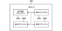
前述したとおり、大気粒子状物質(PM)センサ(「PMセンサ」とも呼ぶ)、例えばPMセンサ101d-1は、とりわけ、粒子を捕捉し、捕捉された粒子を識別し、捕捉された粒子から収集した情報に基づいて解析を実行することによって、大気PM物質を監視するために環境に配備され得る。図2は、図2では素子「202」と標識され、以下では互換的に「202」または「PMセンサ202」と呼ぶ、図1のPMセンサ101d-1のシステム構造図を示す。図2に示すように、いくつかの実施形態では、PMセンサ202は、粒子を基板上に捕捉するための粒子捕捉サブシステム202aと、捕捉された粒子に対して感知動作を実行するための感知サブシステム202bと、粒子が捕捉された基板をクリーニングまたは補充するための補充サブシステム202cと、捕捉された粒子の感知に基づいて解析動作を実行するための解析サブシステム202dと、を含み得る。これらのサブシステムの機能性の概要は、例示的な実施形態によるPMセンサ202の動作原理を示す、少なくとも図3に関連してこれから説明する。
Atmospheric Particulate Matter (PM) Sensor As previously mentioned, an atmospheric particulate matter (PM) sensor (also referred to as a “PM sensor”), such as
一般的に、粒子捕捉サブシステム202aは、図3に示すように、空気中の粒子P1、P2、P3、P4、P5、P6など(集合的に「P」または「粒子P」)を基板202a-1に向けて、かつその上へと駆動するのに使用され得る。粒子Pは、例えばポンプおよび/または電気集塵器(ESP)(図2には示していない)を用いて、基板202a-1に向けて駆動され得る。捕捉された粒子P4、P5、およびP6(集合的に「CP」または「捕捉された粒子CP」)は、基板202a-1上に収集される。次に、感知サブシステム202bは、収集された粒子CPに関する情報を検出または測定するのに使用される。以下でさらに詳細に説明するように、感知サブシステム101は、光学感知、音響感知、電磁感知、誘電感知、および当業者に既知の他のものを提供するように構成された、1つ以上のセンサ(および相補的な構成要素)を含み得る。例えば、図3に示すように、感知サブシステム202bは、光学センサ202b-1、例えば感知素子(例えばピクセル)のアレイを含む電荷結合素子(CCD)または相補型金属酸化膜半導体(CMOS)チップであるか、またはこれらを含み得る。基板は、図3に示すように、粒子から散乱した光が1つ以上のピクセルによって受け取られるように、センサに近接していてよい。いくつかの実施形態では、感知サブシステム202b-1は、捕捉された粒子とチップまたは光学センサ202b-1との間に配された介在レンズまたはレンズシステムを含み得る。レンズまたはレンズシステムは、さまざまな倍率のカメラまたは顕微鏡に似た、光学センサ上の粒子から散乱した光の画像を作り出すのに使用され得る。図3に示すように、感知サブシステム202b-1は、捕捉された粒子を照らす、照明光源(例えば光源)を含み得、粒子に光を散乱させ、センサ202b-1は、とりわけ、照明光源によって向けられた光の散乱に基づいて、情報を検出し得る。補充システム202cは、粒子CPが収集された基板または基板の表面をクリーニングおよび/または補充するのに使用され得る。感知サブシステム202bによって検出される、収集された粒子CPのデータ(例えば画像)は、解析サブシステム202dに送信されるか、または解析サブシステム202dが利用できるようにされ、解析サブシステムは、次に、データを分析して、とりわけ、PMセンサ202の目的または設定にしたがって、収集された粒子CPおよび/または粒子が収集される環境(例えばスマート環境101)に関する情報を導き出すか、または計算することができる。以下でさらに詳細に説明するように、解析サブシステム202dの機能性のすべてまたは一部は、PMセンサ202において、もしくはPMセンサ202によって、および/または1つ以上の接続されたデバイス(例えば、クラウドコンピューティングシステム105、管理システム107)によって、提供され得る。
In general, the
図4は、PMセンサ302の例示的な一実施形態の外側の斜視図を示す。図示のとおり、PMセンサ302は、空気の取り込みを駆動するかまたは促進するポンプ302a-1と、粒子が捕捉される基板の一部として機能するか、もしくはそのような基板の一部であってよいテープケース302a-2と、少なくともテープケース302-a-2を駆動するように構成されたモータ302a-3と、を含む。ポンプ302a-1、テープケース302a-2、およびモータ302a-3は、PMセンサ302の捕捉サブシステム302aの一部を形成するか、またはそのような一部であってよい。図3には示されていないが、本明細書に記載するように、捕捉サブシステム302aは、基板、集塵器、ろ過システム、および当業者に既知の他のものなど、粒子を捕捉するための他の特徴部および/または構成要素を含み得ることを理解されたい。依然として図4を参照すると、PMセンサ302は、照明光源302b-1およびセンサ302b-2を含み、これらは一緒に感知サブシステム302bの一部を形成するか、またはそのような一部である。いくつかの実施形態では、テープケース302a-2(および/またはその中のテープ)ならびにモータ302a-3は、さらに、または代わりに、補充サブシステム302cの一部を形成し得る。すなわち、モータ302a-3は、テープケース302a-2内に配されたローラーを起動させるのに使用され得、これによって、次に、粒子が収集されたテープは、テープのロールまたはストリップからのテープの新しくきれいなまたは粒子を含まないセクションと交換され得る。図4には示していないが、PMセンサ302は、得られた粒子データを処理するために解析サブシステムを含み得ることを、理解されたい。解析サブシステムは、PMセンサ302に埋め込まれるか、またはこれに通信可能に連結され得る。
FIG. 4 illustrates an exterior perspective view of an exemplary embodiment of
PMセンサ202およびそのサブシステムは、少なくとも図5のアクティビティ図に関連してさらに詳細に説明する。
大気PM監視およびPMセンササブシステム
図5は、大気粒子状物質(PM)を監視するための例示的な1つのプロセス400を示すアクティビティ図である。プロセス400では、大気粒子状物質の監視は、図2のPMセンサ202などのPMセンサ、およびそのサブシステムを用いて実行され得る。PMセンサのサブシステムは、図5の監視プロセスに関連して以下で説明する。
Atmospheric PM Monitoring and PM Sensor Subsystem FIG. 5 is an activity diagram illustrating one
粒子捕捉サブシステム
図5に示すように、監視プロセスは、ステップ450で始めることができ、ステップ450では、空気が環境から収集され、空気からの粒子は、PMセンサ202の粒子捕捉サブシステム202aによって捕捉される。さまざまな技術を使用して、空気をPMセンサ202内へ、および/または基板に向かって駆動し、収集された空気から粒子を捕捉することができる。このような技術は、機械的圧縮、吸引もしくは放散ベースの捕捉、静電捕捉、音響および/もしくは誘電泳動力(dieletrophoretic forces)を用いた捕捉、空気を含む流体中で粒子を操作する手段、および当業者に既知の他のもののうちの1つ、または組み合わせを含み得る。いくつかの実施形態では、粒子の捕捉は、空気からの粒子を基板に向かって、また基盤へとそらすことを含む。いくつかの実施形態では、粒子の捕捉は、捕捉された粒子が基板と接触しているか、または基板と接触している別の粒子もしくは物体と接触していることを含む。いくつかの実施形態では、粒子の捕捉は、粒子が基板と接触しているか、または実質的に近接している間に、粒子の位置を制御することを含む。粒子の捕捉は、いくつかの実施形態では、所望の感知動作を粒子に対して実行するのに十分長い時間にわたって行われる。いくつかの実施形態では、粒子は、十分な付着または捕捉力で、基板と接触しているか、または実質的に近接している場合に、捕捉されたとみなされ、粒子は、一定の空気もしくは空気流条件下では、または逆もしくは切り離しアクションもしくは力が加えられなければ、基板から分離せず、また、捕捉されなくはならない。
Particle Capture Subsystem As shown in FIG. 5, the monitoring process may begin at step 450 where air is collected from the environment and particles from the air are captured by the
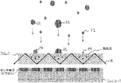
いくつかの実施形態では、捕捉サブシステム202aは、収集された空気から粒子を捕捉するために電気集塵を実行するように構成され得る。当業者には既知であるように、電気集塵は、電位または電荷が生成され、収集された空気に印加される技術である。電荷は、空気の流れを妨げずに空気から粒子を分離するように構成される。図6は、例示的な実施形態に従って、電気集塵を用いて空気から粒子を捕捉するための一連のステップ500を示す。図6に示すように、ステップ550では、粒子捕捉サブシステム202aは、基板202a-1および電極202a-2を含む。図6は、サブシステム202a内部で、粒子P1、P2、およびP3などを囲む無色のエリアで示されている、空気中に含まれる例示的な粒子P1、P2、およびP3も示す。
In some embodiments, the
次に、ステップ552では、電荷Eが電極202a-2に印加され、電荷担体C1、C2、C3など(集合的に「C」もしくは電荷担体C」)が、生成され、収集された空気中に分散する。電極202a-2に印加された電荷Eは、基板202a-1の電荷とは反対であることを、理解されたい。ステップ554では、電荷Eを電極202a-2に印加することによって放出された電荷担体Cは、次に、粒子Pによって拾われて、荷電粒子Pを、逆荷電基板202a-1に向かってそらすか、またはこれに引き寄せる。電荷を電極202a-2に印加し続け、よって、電荷担体Cを粒子Pに印加し続けることにより、粒子Pが、図6のステップ556に示すように、基板202a-1において捕捉または堆積される。いくつかの実施形態では、電気集塵は、基板202a-1から粒子を除去するのに使用され得る。ステップ558で示すように、ステップ552で印加された電荷とは逆の電荷Eが、電極220a-2に印加され、それによって、粒子は、同荷電基板220a-1から分離される。いくつかの実施形態では、ステップ558の電気集塵を用いた粒子の除去が、以下でさらに詳細に説明するように、補充プロセスに関連して実行され得ることを、理解されたい。
Next, in
図7は、電気集塵を実行するための電荷生成および分布の例としての一実施形態を示す図である。より具体的には、図7は、粒子捕捉サブシステム202aの例示的な構成要素を示す。図示のとおり、粒子捕捉サブシステム202aは、DC電源202a-3と、イオン発生器202a-4と、電極202a-2を構成するイオン放出ブラシと、複数の基板202a-1(その上で粒子を捕捉するそれらの構成を考慮し、互換的に「捕捉基板」と呼ばれる)と、を含み得る。いくつかの実施形態では、イオン発生器202a-4は、~3000Vの電圧と、1cc当たり19億個のイオンと、を生じ得る。捕捉基板202a-1は、非限定的な例示的な一実施例では、銅を含み得るか、もしくは銅で作られてよく、かつ/または金属研磨剤およびアルミナ懸濁液で研磨され得る。捕捉基板202a-1の非限定的な例示的な一実施例は、約99%の銅で形成され、約0.2mmの厚さを有し得る。いくつかの実施形態では、捕捉基板は、約1cm2ある。
FIG. 7 is a diagram illustrating one example embodiment of charge generation and distribution for performing electrostatic precipitation. More specifically, FIG. 7 shows exemplary components of
依然として図7を参照すると、図から分かるように、DC電源202a-3は、正電荷および負電荷を発生し得る。正電荷および負電荷は、イオン発生器202a-4に伝達され得る。したがって、イオン発生器は、正電荷を電極202a-2に、負電荷を捕捉基板202a-1に伝達し得る。その結果、汚染された空気が捕捉基板202a-1間を流れるように駆動されるか、または許容されると、正電荷担体は、電極202a-2によって、収集された空気上へと放出される。捕捉基板202a-1の負電荷は、逆荷電粒子を基板202a-1に向かってそらす。粒子が除去された空気は、PMセンサ202から流出することができる。
Still referring to FIG. 7, as can be seen, the
いくつかの実施形態では、前述した電気集塵機能性に加えて、またはその代わりに、粒子捕捉サブシステム202aは、図5のステップ450で空気を収集し粒子を捕捉するためのろ過システムを含み得る。機械的ろ過システムは、例えば、いくつかの実施形態では、粒子捕捉サブシステム202aにおいて、空気取り込みシステム、空気注入システム、空気ポンプ、真空ポンプ、および/または空気を動かし、かつ/もしくは粒子もしくは粒子状物質が捕捉される空気の流れを駆動するように構成された、任意のタイプのシステムもしくは方法を提供することによって、補助または促進され得る。いくつかの実施形態では、風などによる空気の自然な動きは、空気を受動的に動かすために使用または依存され得る。PMセンサは、PMセンサを通過する空気の量を測定するように構成されたエアフローセンサを含むか、またはこれに通信可能に連結され得る。いくつの実施形態では、PMセンサの容積(例えば、数ミリリットル)は、サンプリングされる空気の体積(例えば、数ミリリットルから1リットル超)と比べて小さい。例えば、PMセンサの基板面積は、いくつかの例示的な実施例では、約0.1mm×0.1mm未満から約1cm×1cm、また、およそ数平方センチメートル以上までの範囲であってよい。空気の流量は、いくつかの例示的な実施例では、毎分約1立方センチメートル(sccm)未満から、約10、100、1000、10,000、100,000sccmまたはそれ以上までの範囲であってよい。いくつかの実施形態では、PMセンサは、より小さい流速で粒子状物質をより効率的に捕捉できるように、空気を圧縮するよう構成され得る。
In some embodiments, in addition to or instead of the electrostatic precipitator functionality described above, the
図8は、例示的な実施形態によるろ過システム202a-5を示す。ろ過システム202a-5は、繊維(互換的に「ろ過膜」および「繊維膜」とも呼ばれる)で形成され、空気が中を通って流れるときに空気から粒子を捕捉するか、またはとらえるように構成された、フィルターなどであってよい。いくつかの実施形態では、フィルターおよび/またはその繊維は、粒子が捕捉される基板であると考えられ得ることを、理解されたい。例えばフィルターは、高性能微粒子捕集効率(HEPA)フィルターなどであってよい。いくつかの実施形態では、ろ過システム202a-5は、ランダムに配列され得る、繊維で形成され得る。当業者に既知であるように、繊維の特徴は、PMセンサ202の意図する目的に基づいて変化し得る。例示的な一実施例では、フィルター202a-5の繊維は、ガラス繊維で構成され、約0.5~約20μmの直径を有し、かつ/または約0.3μm超であるエアスペースを互いの間に有し得る。
FIG. 8 shows a
ろ過システム202a-5は、空気ポンプもしくは取り込みシステムと組み合わせるなどして機械的ろ過に使用されるか、または、本明細書に記載される電気集塵構成要素と組み合わせるなどして電気ろ過に使用され得る。図9A、図9B、および図9Cは、粒子がろ過システム202a-5によって、すなわち横取り、衝撃、および放散それぞれによって、とらえられるか、もしくは捕捉されるか、または、それが可能となる、さまざまな方法を示している。横取りは、粒子とフィルターとの間で静電またはファンデルワールス力などの引力を使用し、それによって、粒子をフィルターの表面に引き付けることを指す。衝突に基づく捕捉は、フィルター表面への粒子の衝突(例えば、直接衝突)を指す。放散に基づく捕捉は、粒子のランダム運動を指し、これは、空気流と組み合わせて、フィルター表面での粒子の捕捉を生じる。機械的ろ過では、粒子は、横取り、衝撃、および放散のうちの1つ以上を通じてとらえられ得る。フィルター(例えば基板)の繊維によって捕捉された粒子は、次に、粒子に関する情報を入手するためにさらに測定または分析され得る。いくつかの実施形態では、ろ過システムは、電気集塵と共に使用されて、例えば、粒子の捕捉を高めることができる。例えば、前述したとおり、空気中の粒子は、フィルターおよび/もしくは繊維であるかまたはそれらを含み得る基板の電荷とは逆の電荷で帯電されてよい。
いくつかの実施形態では、テープまたは類似の物体が、粒子が捕捉される粒子捕捉サブシステムの基板202a-1として使用され得る。テープは、ロールまたはストリップで提供され得、ローラーによって動作され得る。したがって、テープは、粒子が捕捉され得るテープのロールまたはストリップから、きれいでありかつ/または粒子を含まない、テープの別のセクションを露出するために、所望の期間において機械的に前進され得る。いくつかの実施形態では、テープは、導電性材料で形成され得、電荷は、テープに伝達されて、図6および図7に関連して前述したように電気集塵をもたらし、それによって、逆荷電粒子を引き付けることができる。いくつかの実施形態では、テープは、ろ過システムに似ているか、またはそれに似るように構成された、繊維で作られ得、図8、および図9A~図9Cに関連して前述したろ過システムと同じように、粒子は、感知のために横取りされるか、または捕捉され得る。いくつかの実施形態では、非導電性テープが、基板の表面として、または基板の表面上に設けられ得る。補充能力を提供する手段としてテープを使用することは、補充サブシステム202cに関連して以下でさらに詳細に説明する。
In some embodiments, a tape or similar object may be used as the
いくつかの実施形態では、粒子が捕捉される基板は、基板上での粒子の付着または捕捉を高めるために改質または変化され得る。例えば、基板は、接着層(例えば、接着グルーの層)または分子層を含み得る。いくつかの実施形態では、ガラス基板は、シランの化学的性質を用いて、改質されて、基板の表面を、親水性、疎水性、親油性、疎油性などにすることができる。他の基板は、マイクロスケールまたはナノスケールでテクスチャを付けられて、クリーニングを容易にするか、または別様にデバイスの機能を高めることができる。 In some embodiments, the substrate on which the particles are trapped can be modified or altered to enhance adhesion or trapping of the particles on the substrate. For example, the substrate can include an adhesive layer (eg, a layer of adhesive glue) or a molecular layer. In some embodiments, the glass substrate can be modified using silane chemistry to render the surface of the substrate hydrophilic, hydrophobic, oleophilic, oleophobic, and the like. Other substrates can be textured at the microscale or nanoscale to facilitate cleaning or otherwise enhance device functionality.
依然として図5の監視プロセスを参照すると、いくつかの実施形態では、PMセンサ202は、動的監視および調節をもたらすために、(例えば、その中に埋め込まれるか、または1つ以上の通信可能に連結されたシステムもしくはデバイスによって提供される)ハードウェアおよび/またはソフトウェアを含み得る。すなわち、いくつかの実施形態では、このような動的監視および調節が、(1)PMセンサ202、(2)センサ202のサブシステム、および(3)クラウド105および/または管理システム107など、PMセンサ202と通信しているシステムおよびデバイスの、埋め込まれるか、もしくは通信可能に連結されたハードウェアおよび/またはソフトウェアのうちの1つまたは組み合わせによって、識別され、トリガーされ、かつ/または実行され得る。例えば、図5では、ステップ450で、いったん空気が収集され、粒子が捕捉されたら、ステップ452において、要求または要望によって動的調節がトリガーされるかどうか、またはトリガーされているかどうかについて、判断することができる。このような判断は、PMセンサ202、そのサブシステム、ならびに/またはこれらに通信可能に連結されたデバイスおよび/もしくはシステムのうちの1つ以上によって実行され得ることを、理解されたい。ステップ452の動的監視および判断(および、ステップ454の対応する調節の起こり得る実行)は、ステップ450の粒子捕捉に続くものとして例示されているが、動的監視に関するこのような判断および実行ステップは、特定のPMセンサ202について最適もしくは適切とみなされる場合、図5に示すアクティビティ中にわたるさまざまな時点で、および/または他のプロセスと同時に、実行され得ることを、理解されたい。すなわち、このような動的処理は、例えば、空気を収集することおよび/もしくは粒子を捕捉すること(ステップ450)、動的調節が要求または要望によりトリガーされるかどうか、またはトリガーされているかどうかを判断すること(ステップ452)、ならびに、必要な調節(ステップ454)を反復して、調節がその反復に関連してこれ以上トリガーされないかもしくはトリガーされていないとステップ452で判断されるまで、実行すること、のフィードバックループを用いて、実行され得る。
Still referring to the monitoring process of FIG. 5, in some embodiments,
図5に示すように、いくつかの実施形態では、ステップ452で、PMセンサ202は、動的調節がトリガーされているかどうか(例えば、必要とされるか、または要望されているかどうか)を判断することができる。このような動的調節は、PMセンサ202、そのサブシステム、および/またはその/それらの機能性の任意の態様に関連し得る。判断は、例えば、(1)事前に記憶されるか、もしくは事前に決定され、かつ/または(2)リアルタイムで、自動的に、かつ/もしくはユーザ入力データと共に、識別され得る、モデル、ルールおよび/または閾値に基づいて、行われ得る。ステップ452の動的判断に関連して実行される動的チェックの非限定的で例示的な一実施例は、捕捉サブシステム202aによって収集または駆動されている空気の流れ(例えば、空気の体積)が調節する必要があるかどうか、または調節されるべきかどうかである。これは、例えば、ステップ450で収集されている空気の量または体積が、小さすぎるか、または大きすぎて所望の量の粒子状物質を分析のために捕捉できないか、またはとらえることができないと判断された場合に、当てはまり得る。さらに、いくつかの実施形態では、サンプリングされる空気の体積のこのような調節または調整は、低レベルの汚染から高レベルの汚染にPMセンサ202の感度および/またはセンサダイナミックレンジを合わせるために実行され得る。収集されている空気の量または体積を調節しなければならない、さまざまな理由が存在し得ることを、理解されたい。このような判断は、所与の量の空気が収集され、かつ/もしくは所与の収集時間が発生した後で行われ得、かつ/または、空気収集および粒子捕捉ステップ中にリアルタイムで行われ得る。
As shown in FIG. 5, in some embodiments, at
依然として図5のステップ452を参照すると、収集された空気の体積が測定され、その値は、例えば空気が収集されているときの、閾値の値または範囲と比較され得る。対応するルールが、その比較に基づいて適用され、空気流の増減が必要とされるか、もしくは要望されるかどうか(ステップ452からの「はい」の分岐)、またはそのような空気流が、いかなる空気流の調節も必要とされず要望されないように許容可能な閾値以内であるかどうか(ステップ452からの「いいえ」の分岐)を判断することができる。空気流の変化などの動的調節が、ステップ452において、必要とされるか、または要望されるとみなされた場合、そのような調節(または複数の調節)がステップ454で実行され得る。調節の種類は、閾値、ルールおよび/またはモデルに基づいていてよい。調節は、一連のサブステップまたはサブ調節を用いて実行され得、所望もしくは目標の閾値またはルールが達成されるまで漸進的な調節が行われることを、理解されたい。例えば、空気流を増やさなければならないと判断されたら、捕捉サブシステム202aは、所望のとおりまたは最適とみなされる場合に(例えば、一回もしくは漸進的に)調節されて、空気の体積の欠如を補う。空気流を増やす観点から、例えば、ポンプの動力または設定は、より多くの空気をPMセンサ202に注入するために増やすことができる。電気集塵が捕捉サブシステム202aによって使用される、いくつかの実施形態では、電極に対する、よって粒子に伝達される、電荷の量は、増やされ得る。本明細書に記載され、当業者に既知である、これらおよび他の種類の動的調節は、ステップ452および454それぞれにおいて、ならびにPM監視プロセス全体にわたって、トリガーされ(例えば、必要とされ、要望され)かつ実行されるよう判断され得ることを、理解されたい。さらに、このような判断および調節は、当業者に既知のさまざまな方法で実行され得る。
Still referring to step 452 of FIG. 5, the volume of collected air may be measured and compared to a threshold value or range, for example, when air is being collected. A corresponding rule is applied based on the comparison to determine whether an increase or decrease in airflow is required or desired (the "yes" branch from step 452), or whether such airflow It may be determined whether it is within an acceptable threshold (the "no" branch from step 452) so that no airflow adjustments are needed or desired. If dynamic adjustments, such as changes in airflow, are deemed necessary or desired at
次に、図5に示すように、フォークノードN1において、PMセンサ202は、空気収集または粒子捕捉閾値が満たされているかどうかについて、ステップ456で判断を行い(フォークノードN1からのエッジE1)、かつ/またはステップ450で新たなもしくは継続した空気収集および粒子捕捉を実行する(フォークノードN1からのエッジE2)ことができる。すなわち、ステップ456で、PMセンサ202および/または粒子捕捉サブシステム202aは、例えば、閾値または所与の量もしくは体積の空気が収集されて粒子がそこから除去されているかどうか、空気を収集し粒子を捕捉する閾値時間に到達しているかどうか、および/または、閾値もしくは所与の量の粒子が捕捉されたかどうか、を判断することができる。例えば、PMセンサ202および/または捕捉サブシステム202aは、感知が、例えば、約5分ごとに、または約1時間粒子を捕捉した後で、実行されるようにプログラムされ得る。すなわち、PMセンサ202および/または捕捉サブシステム202aは、粒子が、表面上で、先に収集された粒子より上に蓄積し続ける、連続または不連続のサンプリング累積モードで動作され得るが、それにもかかわらず、大気汚染または粒子状物質レベルに関する情報を提供することができる。任意のこのようなルールおよび閾値、例えば空気収集、粒子捕捉、および粒子感知のためのスケジュールに関するものは、当業者に既知であるように、感知を開始するために適用または使用され得ることを、理解されたい。
Next, as shown in FIG. 5, at fork node N1,
いくつかの実施形態では、関連する閾値、例えば空気収集または粒子捕捉閾値が満たされたと、ステップ456で判断された場合、PMセンサ202は、ステップ458で感知プロセスを実行する(ステップ456からの「はい」の分岐)。別の状況では、閾値が満たされていないとステップ456で判断された場合、PMセンサ202は、ステップ450で、空気の収集と粒子の捕捉を続ける(ステップ456の「いいえ」の分岐およびE2エッジ)。このような反復は、例えば、捕捉された粒子に対して感知動作が実行されるのをトリガーする閾値が満たされる(例えば、約1時間の粒子捕捉時間が発生している)まで、実行され続け得る。本明細書に記載するように、ステップ458で実行される、捕捉された粒子の感知は、PMセンサ202の感知サブシステム202bによって行われ得、これについてさらに詳細に説明する。
In some embodiments, if it is determined at
感知サブシステム
前述したとおり、感知サブシステム202bは、ステップ450で捕捉された粒子に関する情報を測定および/または検出するように構成された、1つ以上のハードウェアおよび/またはソフトウェア構成要素で構成される。例えば、感知サブシステムは、センサ、または同じかもしくは異なる感知能力を有するセンサもしくはセンサ素子のアレイを含み得る。感知サブシステム202bのセンサ、またはセンサのアレイによって提供され得る感知の種類の非限定的で例示的な例は、光学感知、音響感知、電磁感知、誘電感知、および当業者に既知の他の感知を含み得る。感知サブシステム202bに含まれるか、またはこれを形成するセンサおよび他の構成要素の数および種類は、PMセンサ202の種類および目的によって取得しようとする粒子に関する情報の種類に左右され得る。感知サブシステム202bのセンサの非限定的な例は、容量センサ、磁気センサ、超伝導量子干渉素子(SQUID)センサ、圧電センサなどを含み得る。いくつかの実施形態では、複数の感知方式が、捕捉された粒子に関する追加情報を得るために感知サブシステム202bによって使用され得る。さらに、センサは、感知素子のアレイを含み得、捕捉された粒子は、1つ以上の感知素子によって感知され得る。感知素子は、基板上で捕捉された種々の粒子に対して別様に機能し得る。よって、カメラによる撮像では、種々の粒子により散乱した光は、カメラの種々の群の感知素子(例えばピクセル)に衝突し得る。
Sensing Subsystem As previously mentioned, the
本明細書に記載するように、撮像のための感知サブシステム202bは、当業者に既知であるように、さまざまな種類の検出器(例えば、相補型金属酸化膜半導体(CMOS)、電荷結合素子(CCD)、容量センサ、および本明細書に記載され当業者に既知である他のもの)、さまざまな種類の照明光源(例えば、発光ダイオード(LED)、斜めの照明(glancing illumination)、基板を通した導波性)、および/またはさまざまな種類の介在光学システム(例えば、直接検出、レンズの使用)を含み得る。
As described herein, the
いくつかの実施形態では、PMセンサ202は、感知サブシステム202bがカメラを含む、撮像ベースのシステムとして設計され得る。感知システム202bは、照明光源も含み得、これは、捕捉された粒子を照らすか、またはこれに光を向けるのに使用され得る。粒子を照らすことにより、光は粒子によって散乱され、次に、サブシステム202bのセンサによって検出される。いくつかの実施形態では、散乱光の検出は、散乱光が、他の検出された光(例えば、基板により反射された光)と比べて、最も高い電位を有することにより、画像センサによって達成され得る。当業者に既知であるように、種々の粒子が、種々のおよび/または独自の方法で、光を散乱させ得る。その結果、散乱光の特徴(例えば、パターン、強度)は、粒子の検出および/または撮像に寄与する。いくつかの実施形態では、サブシステム202bのセンサは、散乱光により検出された最も小さい粒子が、数十ナノメートルの範囲内にあり得るように構成され得るが、当然、センサは、PMセンサの目的に最適とみなされるような範囲のサイズの粒子を捕捉するよう構成され得る。このような粒子のサイズは、例えば、またとりわけ、散乱光の強度によって推測され得る。よって、このような場合、数百ナノメートルを超える粒子は、分解され(resolved)得る。感知される最も大きい粒子は、いくつかの例示的な実施例では、数百マイクロメートル以上の範囲であってよい。いくつかの実施形態では、粒子の総数は、適切な較正手順によって得ることができることを、理解されたい。
In some embodiments,
図10Aは、電気集塵タイプの捕捉サブシステムと共に使用され得る、PMセンサ202の態様の例示的な構成を示す。図10では、感知サブシステム202bは、捕捉された粒子の光学感知のためにセンサ202b-1および照明光源202b-2(互換的に「光源」とも呼ばれる)を含む。センサ202b-1は、捕捉された粒子を撮像するように構成された、当業者に既知であるような、カメラなどであってよい。いくつかの実施形態では、カメラは、相補型金属酸化膜半導体(CMOS)カメラモジュールの一部であってよい。さらに、照明光源202b-2は、当業者に既知であるような、紫外線(UV)(例えば近紫外線)光源、または発光ダイオード(LED)の光(例えば、可視光LED)などであってよい。以下でさらに詳細に説明するように、照明光源202b-2およびカメラ202b-1は、とりわけ基板の光透過特徴に基づいて、互いに対して、および/または基板および捕捉された粒子に対して位置づけられ得、粒子の最適な撮像が達成され得る。
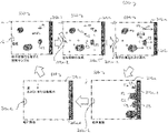
FIG. 10A shows an exemplary configuration of aspects of
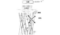
依然として図5のステップ458を参照すると、捕捉された粒子の撮像の感知動作は、図10Aに示すように実行され得る。すなわち、図10Aに示すように、粒子P1、P2、およびP3は、例えば、図5のステップ450に従って、基板202a-1上で捕捉される。ステップ458の感知プロセスをトリガーすると、感知サブシステム202bの照明光源202b-2が、光を捕捉された粒子および基板202a-1に向ける。図10Aのサブシステム202bの照明光源202b-2は、センサ202b-1が散乱光を検出し、それによって粒子を撮像することができるように、捕捉された粒子が照明光源202b-2の入射光を散乱させるよう位置づけられるか、または構成されることを理解されたい。いくつかの実施形態では、この照明は、基板202a-1および/または捕捉された粒子に対して(例えば視射角での)斜めの光を生じる照明光源202b-2によって、または、照明光源202b-2からの光が捕捉された粒子および/または基板202a-1に鋭角で当たるように、達成され得る。粒子および/または基板に対するこのような照明光源の位置づけは、光が基板によって反射されるのを防ぐか、または低減させることができ、これにより、捕捉された粒子によって散乱した光の感度を上げることができる。
Still referring to step 458 of FIG. 5, the sensing operation of imaging the trapped particles may be performed as shown in FIG. 10A. That is, as shown in FIG. 10A, particles P1, P2, and P3 are captured on
本明細書に記載するように、感知サブシステムは、捕捉された粒子とサブシステムのチップまたはセンサとの間に配された介在レンズ202b-3を含み得る。図10Bは、図10Aに示すものと実質的に同様であるが、センサ202b-1と捕捉された粒子との間に位置づけられたレンズを含む、PMセンサ202の態様の例示的な構成を示す。レンズまたはレンズシステムは、種々の倍率を有する従来のカメラまたは顕微鏡の動作と同じように、捕捉された粒子から、またはこれによって散乱した光に基づいて画像を生成するのに使用され得る。
As described herein, the sensing subsystem may include an intervening
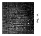
図11Aおよび図11Bは、粒子の撮像に対する照明角度の効果を示す。すなわち、図11Aは、銅基板上で捕捉された粒子の、カメラセンサによって撮られた画像であり、照明光源は、約45°の角度で基板を照らしている。図11Bは、銅基板上で収集された図11Aの粒子の、カメラセンサによって撮られた、しかし約2°の角度で照らされている、画像である。図で分かるように、図11Aの照明角度では、銅基板からの光が、カメラセンサへと反射されるが、図11Bの照明角度では、捕捉された粒子が、カメラセンサによって検出可能となるように光を散乱させる。図11C、図11D、および図11Eは、本明細書に記載される感知ツールおよび技術に従って撮像された、種々の例示的な粒子の画像である。図11Cは、アメリカヤマナラシ(ポプラ)からの木/低木の花粉の画像であり、図11Dは、ニワトコ(Iva xantifolia (giant poverty))からの雑草の花粉の画像であり、図11Eは、シリカ、酸化アルミニウム、酸化カルシウム、酸化カリウム、酸化ナトリウム、酸化鉄、酸化マグネシウム、および酸化チタンでできたアリゾナ試験粉末である。これらの画像の分析は、解析サブシステムに関連して以下でさらに詳細に説明する。 11A and 11B show the effect of illumination angle on particle imaging. 11A is an image taken by a camera sensor of a particle trapped on a copper substrate, with an illumination source illuminating the substrate at an angle of about 45°. FIG. 11B is an image of the particles of FIG. 11A collected on a copper substrate, taken by the camera sensor but illuminated at an angle of about 2°. As can be seen, at the illumination angle of FIG. 11A, light from the copper substrate is reflected to the camera sensor, whereas at the illumination angle of FIG. scatters light into 11C, 11D, and 11E are images of various exemplary particles captured according to the sensing tools and techniques described herein. FIG. 11C is an image of tree/shrub pollen from Aspen aspen (poplar), FIG. 11D is an image of weed pollen from elder (Iva xantifolia (giant poverty)), FIG. Arizona test powder made of aluminum oxide, calcium oxide, potassium oxide, sodium oxide, iron oxide, magnesium oxide, and titanium oxide. Analysis of these images is described in further detail below in connection with the analysis subsystem.
図12Aおよび図12Bは、ろ過ベースの粒子捕捉サブシステムでの撮像に使用され得る、PMセンサ202の態様の例示的な構成を示す。特に、図12Aでは、ろ過ベースの粒子捕捉サブシステムの単繊維が示され、図12Bでは、ろ過ベースの粒子捕捉サブシステムのフィルターの1組の繊維が示されている。より具体的には、図12Aは、感知サブシステムのセンサ202b-1’および照明光源202b-2’を示す。ろ過ベースの捕捉サブシステムのフィルターの繊維、例えば図12Aに示す単繊維は、照らされる光の導波管として機能し得る。したがって、繊維は、入射光を、その繊維を通して、図12Aに示すようなジグザグパターンなどのパターンで導いて、捕捉された粒子によって散乱される光に干渉することができる反射光の量を減らすことができる。図12Aに示すように、繊維は、空気がセンサ202b-1’を通って流れるエリアおよび/またはセンサ202b-1’に近接したエリア間に位置づけられ得、繊維は、捕捉された粒子P1がセンサ202b-1’の方向に光を散乱させる方向に、またはそのような位置もしくは角度から、入射光を導き得る。よって、捕捉された粒子によるこのような散乱は、センサ202b-1’によって検出され得る。すなわち、図12Aに示すように、光が(1)基板を照らし、導波管として機能する繊維(もしくは複数の繊維)によって、および/またはこれを通じて、センサから離れる方向、および/または捕捉された粒子によって散乱された光への干渉を最小限に抑える方向に、導かれ、かつ(2)繊維に付着するか、または繊維によって捕捉された粒子P1などの粒子を照らすにつれて、光は、図10Aに関連して前述した検出または撮像と同じように、捕捉された粒子の検出または撮像を可能にする様式で、またはそのような方向に、センサ202b-1’に向かって散乱する。
12A and 12B show exemplary configurations of aspects of
図12Bでは、ろ過ベースの粒子捕捉サブシステムの複数の繊維が示され、複数の粒子がその上またはその間に捕捉されている。照明光源202b-2’’が、図12Aに示すのと実質的に同じように、ろ過ベースのシステムの複数の繊維の方に光を向けるように構成されている。よって、基板に到達する照明光源からの光は、繊維自体を通って導かれるが、捕捉された粒子に到達する光は、図12Bに示すように、センサの方向に散乱する。対応するセンサ(図12Bは示されていない)は、散乱光を検出し、それによって、とりわけ、光を散乱させた1つまたは複数の粒子の画像を生成することができる。図5のステップ458で実行される撮像または他の感知のタイプまたは量は変化し得ることを、理解されたい。例えば、さまざまな種類および量の撮像または他の感知が、ステップ458で実行され得る。
In FIG. 12B, multiple fibers of a filtration-based particle trapping subsystem are shown with multiple particles trapped thereon or between them. An
当業者に既知であるように、いくつかの実施形態では、2つの期間の間の粒子の変化を検出するために、1つの期間にサンプリングされるデータが、別の期間にサンプリングされるデータから減算され得る。よって、例えば、粒子捕捉が連続的に実行され、撮像(および/または他の感知)がおよそ1時間に一度実行され、捕捉基板の補充(例えば、クリーニング、交換)がおよそ5時間ごとに実行される、スケジュールでは、およそ時間2で撮られた画像を、およそ時間1で撮られた画像と比較して、時間1と時間2との間に捕捉された粒子のみを検出または単離することが可能である。
As known to those of skill in the art, in some embodiments, data sampled in one period is modified from data sampled in another period to detect changes in particles between the two periods. can be subtracted. Thus, for example, particle capture is performed continuously, imaging (and/or other sensing) is performed approximately once an hour, and capture substrate replenishment (e.g., cleaning, replacement) is performed approximately every 5 hours. The schedule may compare an image taken at about
図10A、図10B、図12A、および図12Bに関連して前述した感知システムの配列は非限定的な例であることを、理解されたい。当業者は、センサ、照明光源、粒子捕捉基板、および他の構成要素が、捕捉された粒子の最適な撮像または他の感知を得るよう構成され得る、多くの方法を理解するであろう。このような構成は、例えば、センサ、照明光源、粒子捕捉基板、および他の構成要素の特徴(例えば、種類、材料、光透過率など)、ならびにPMセンサ202の意図する目的または用途に基づき得る。いくつかの実施形態では、照明光源および画像センサは、これは、捕捉された粒子の撮像の品質に影響を及ぼし得る、基板から(または捕捉された粒子から以外の)画像センサへの光の直接反射を避けるように位置づけられ得る。いくつかの実施形態では、光は、基板の、画像センサが位置づけられる側とは反対側から、画像センサの方向に向けられ得る。このような実施形態では、基板は、透明であってよく、かつ/または、光を通過させ得る光透過特性を有する。このように、透明基板の結果として、オプションとして非透明粒子によって生じる陰になるかまたはあまり照らされないエリアと組み合わせて、通過する光は、粒子を撮像するか、またはそれに関する他の情報を得るのに使用され得る。
It should be appreciated that the sensing system arrangements described above in connection with FIGS. 10A, 10B, 12A, and 12B are non-limiting examples. Those skilled in the art will appreciate the many ways sensors, illumination sources, particle trapping substrates, and other components can be configured to obtain optimal imaging or other sensing of trapped particles. Such configurations may be based, for example, on the characteristics of the sensor, illumination source, particle trapping substrate, and other components (eg, type, material, light transmittance, etc.), as well as the intended purpose or application of
感知サブシステム202bの照明光源からの光の波長は、粒子の感知のさまざまな態様に影響を及ぼす。例えば、光の波長は、非粒子物体(例えば基板)からの反射光の量、および/または粒子により散乱される光の量もしくは強度に影響を与え得る。よって、照明光源からの光の波長は、特に他の光に対する、粒子またはそれらの散乱光の最適な感度を達成するために設定または調節され得る。いくつかの実施形態では、異なる波長(例えば、可視、UV、赤外線)、または分光学的方法(例えば、赤外線、ラマン分光法)による照明が、捕捉された粒子に関する追加情報、例えば表面の粗さ、サイズ、または組成を推測するのに使用され得る。
The wavelength of light from the illumination source of
再び図5の監視プロセスを参照すると、いったん感知がステップ458で、前述したとおり実行されると、PMセンサ202は、(1)動的調節がトリガーされるかどうか、もしくはトリガーされているかどうかを判断し(フォークノードN2からのエッジE3);(2)基板もしくは基板表面の補充がトリガーされているかどうかを判断し(フォークノードN2からのエッジE4);かつ/または(3)さまざまな他のプロセスを実行することができる、フォークノードN3に進み(フォークノードN2からのエッジE5)得る。前述したとおり、3つのアクティビティエッジE3~E5、およびそれらの下流のプロセスは、連続してまたは同時に(例えば完全にもしくは部分的に)実行され得る。このような連続したまたは同時の処理は、本明細書に記載されるその他のプロセスにも同様に適用される。例えば、ステップ460の動的調節判断は、ステップ450で空気が収集され、粒子がそこから捕捉されるのと同時に実行され得る。
Referring again to the monitoring process of FIG. 5, once sensing is performed at
図5のステップ460では、PMセンサ202は、動的調節が必要とされる(または要望される)かどうかを判断することができる。ステップ452に関連して前述したように、動的監視(例えば、ステップ460の判断、ステップ462の実行)は、PMセンサ202、そのサブシステム、またはこれに通信可能に連結されたデバイスおよびシステムによって、実行され得る。ステップ460の判断は、PMセンサ202、そのサブシステム、および/またはその/それらの機能性の任意の態様に関連し得る。やはり前述したように、動的調節監視は、(1)事前に記憶されるか、もしくは事前に決定されるか、または(2)リアルタイムで、自動的に、および/もしくはユーザ入力データと共に、識別され得る、モデル、ルールおよび/または閾値に基づいていてよい。
At
いくつかの実施形態では、判断ステップ460に関連して実行される動的なチェックは、粒子感知ステップ458に関する特徴に関連し得る。前述したように、任意のタイプの調節を、(例えばステップ452および454に関連して前述したものを含め)ステップ458で監視することができるが、粒子感知に関する調節は、ステップ458の感知より前に、それと同時に、またはその後で、実行され得る。いくつかの実施形態では、これらのタイプの感知関連判断は、ステップ458の感知プロセスの近くで実行され、その感知から導き出された情報は、ステップ460の判断のために使用され得る。
In some embodiments, the dynamic checks performed in connection with
ステップ460で行われる調節に関する判断の非限定的な例は、ステップ458の撮像(もしくは他の感知)プロセスのタイミング;撮像のダイナミックレンジ;照明光源からの光の波長;基板、センサ、および/もしくは照明光源などの構成要素の位置;ならびに/または基板もしくは基板表面の補充(これは、さらに、もしくは代わりに、以下でさらに詳細に説明する、ステップ464および466に関連して実行され得る)に対する必要性もしくは要望、の適切性(例えば、閾値もしくは標準に対する)をチェックすることを含む。例えば、PMセンサ202は、ステップ460で、照明光源からの光の波長を、(1)ステップ458で実行された粒子の画像と、(2)最適または好適な粒子撮像特徴(例えば強度)を示す閾値、ルールおよび/またはモデルとの比較に基づいて、変更すべきかどうかを、判断し得る。当然、これらの例示的な判断、および本明細書に記載され、当業者に既知である他の判断のいずれかが、同時に(例えばステップ460で)実行され得ることを、理解されたい。
Non-limiting examples of decisions regarding adjustments made in
したがって、動的調節が実際に必要とされるか、好ましいか、または別様に所望されることをPMセンサ202がステップ460で判断したら(ステップ460からの「はい」の分岐)、PMセンサは、ステップ462において必要な調節を実行するか、またはその実行を引き起こす。一方、動的調節が必要とされず、好ましくなく、または別様に所望されないことをPMセンサがステップ460で判断したら(ステップ460からの「いいえ」の分岐)、PMセンサは、図5に示すように、フォークノードN3に進む。ステップ462で行われる調節の種類は、ステップ460で行われる判断に基づいていてよい。いくつかの実施形態では、ステップ460の判断は、特定のアクションまたは調節がステップ462で実行されるのをトリガーし得る、ルールの使用を伴い得る。
Therefore, once the
ステップ462で行われる動的調節の非限定的な例は以下を含む:粒子が撮像されるか、もしくは別様に感知される頻度を(例えば、1時間当たりおよそ1回から、1時間当たり4回に)変更すること;センサ、光源、基板、および他の構成要素の、互いに対する位置づけ(例えば、角度、距離)を変更すること;光源の波長を調節すること、ならびに必要に応じた、または所望されるような、当業者に既知である他の調節。 Non-limiting examples of dynamic adjustments made at step 462 include: changing the frequency at which particles are imaged or otherwise sensed (e.g., from approximately once per hour to four per hour). changing the orientation (e.g., angle, distance) of the sensor, light source, substrate, and other components relative to each other; adjusting the wavelength of the light source, and as needed or Other adjustments known to those skilled in the art as desired.
依然として図5を参照すると、ステップ464で、PMセンサ202は、基板および/または基板の表面の補充が必要性によって、もしくは要望によってトリガーされるかどうか、またはトリガーされているかどうかを、判断し得る。いくつかの実施形態では、ステップ464の判断は、PMセンサ202および/または、さらに詳細に説明される、その補充サブシステム202cによって、実行され得る。
Still referring to FIG. 5, at
補充サブシステム
補充の判断および実行は、ステップ464および466で、補充サブシステム202cによって実行され得る。本明細書で使用される用語「補充」は、基板もしくは基板表面をクリーニングすること、または基板を取り換えるか、もしくは交換することを含む。前述したとおり、いくつかの実施形態では、基板は、導電性表面、例えば、銅プレート、フィルター、または導電性もしくは非導電性テープであってよい。いくつかの実施形態では、基板表面は、粒子が捕捉される基板の表面を指すことができる。補充は、基板もしくは基板表面の有用性の期間を延ばすこと、または捕捉され、したがって撮像され得る粒子を変更もしくはリセットすること、を含む、さまざまな理由で、実行され得る。よって、ステップ464では、例えばPM監視プロセスのデータを、予め判断されるか、もしくは動的に計算された閾値と比較することによって、補充が必要とされるか、もしくは所望されるかどうかに関して、判断を行い得る。例えば、ステップ464は、最後の補充以来、所与の粒子捕捉時間に到達したかどうか、または、最後の補充以来、所与の量の粒子状物質が基板もしくは表面上に捕捉されているかどうか、を判断することを含み得る。これらの補充に関連する判断は、図5に示されるプロセス400の任意のステップ中に、また当業者に既知のさまざまなデータのうちのいずれかに基づいて、動的に実行され得る。例えば、閾値が、捕捉された粒子状物質のタイミングもしくは量などの要因に基づいて、必要とされるか、または要望されると判断された場合であっても、補充サブシステムは、PMセンサ202のバッテリが低く、したがって、補充プロセスを延期またはキャンセルしてその有用性の期間を伸ばすことを判断し得る。
Replenishment Subsystem Replenishment determination and execution may be performed by the
よって、補充が必要であるか、または要望されるとステップ464で判断されると(ステップ464からの「はい」の分岐)、補充サブシステム202cは、ステップ466で表面または基板を補充する。一方、補充が必要でないかまたは要望されないとステップ464で判断されると(ステップ464からの「いいえ」の分岐)、PMセンサ202はフォークノードN3に進むことができる。
Thus, if it is determined at
ステップ466で、補充は、補充サブシステム202cによって実行される。ステップ466で実行される補充の種類または他の特徴は、例えば、捕捉される粒子状物質の量、バッテリの残り寿命、および/またはPMセンサ202のスケジュールされた処理に基づいて、予め決定されるか、またはリアルタイムで動的に決定され得る。基板または基板表面を補充するためのウェットおよびドライ技術の非限定的な例は、機械的クリーナー、静電クリーナー、加熱もしくは熱的手段、ならびに導電性および非導電性テープのうちの1つ以上を使用することを含む。PMセンサ202によって使用される補充技術は、基板のクリーニングと比較して交換可能なテープの使用によって影響を受け得る、目標コスト、および/または目標もしくは所望の粒子除去割合(例えば、約90%超の粒子除去、約95%超、99%超などの粒子除去)などの要因に基づいていてよいことを、理解されたい。
At step 466, replenishment is performed by
基板または基板表面をクリーニングする機械的技術は、機械的に動作されるブラシを、基板または基板表面上で、所与の回数、また動的に決定されるか、または予め決定され得る、所与のパターンで(例えば円形、線形)動かすことを含み得る。ブラッシングは、所望の量の粒子状物質が除去されるまで実行され得る。ブラシの特徴は、さまざまであり、基板または基板表面の種類に左右され得ることを、理解されたい。1つの非限定的な例は、ナイロン繊維ブラシである。いくつかの実施形態では、液体または粒子が、基板または基板表面上に分散されて、その機械的クリーニング(例えばブラッシング)を改善することができる。他の種類の機械的技術は、粒子と基板または基板表面との間の取り付け、引き付け、または接触を断つのに十分強くなるように、空気流を制御するのに使用され得る、空気ポンプ、ファン、空気注入および排出システムなどの使用を含み得る。いくつかの実施形態では、接着性裏打ち材料(例えば、ステッカー、接着性ストリップ、接着テープ)の粘着性がある側が、基板の表面と接触させられて、粒子をそこから除去することにより基板をクリーニングすることができる。このような接着性材料のロールが、必要な場合または要望される場合に前進され得るローラーなどの上に設けられ得、先に使用された接着性材料が粒子でいっぱいになり、もはやクリーニングするのに適切に使用することができない場合に、基板のクリーニングを実行するために、新しい接着性材料表面が、基板と接触させられるのに利用可能となる。さらに、いくつかの実施形態では、機械的技術は、捕捉された粒子を除去するか、またはその除去を支援するために振動を使用することを含み得る。例えば、基板は、その上に捕捉された粒子を基板またはその表面からバラバラにするかまたは分離させる十分な力で、振動するか、または振動させられる。熱的方法、例えば基板の加熱は、粒子を除去するのに使用され得る。このような方法は、例えば、蒸発または燃焼によってエーロゾル微粒子を除去するのに使用され得る。熱的方法は、基板の位相を変化させるため、例えば、基板を溶融および凝固させ、それによってその表面を補充するために、使用され得る。粒子は、明細書に記載され、当業者に既知である他の技術を利用して、除去され得る。 The mechanical technique for cleaning the substrate or substrate surface is a given number of times that a mechanically operated brush is moved over the substrate or substrate surface for a given number of times and can be dynamically determined or predetermined. (eg, circular, linear) in a pattern of . Brushing can be performed until the desired amount of particulate matter is removed. It should be appreciated that the characteristics of the brush can vary and depend on the type of substrate or substrate surface. One non-limiting example is a nylon fiber brush. In some embodiments, liquids or particles can be dispersed on the substrate or substrate surface to improve its mechanical cleaning (eg, brushing). Other types of mechanical techniques can be used to control the airflow so that it is strong enough to break the attachment, attraction, or contact between the particles and the substrate or substrate surface, air pumps, fans, etc. , air injection and evacuation systems, and the like. In some embodiments, the sticky side of an adhesive backing material (e.g., sticker, adhesive strip, adhesive tape) is brought into contact with the surface of the substrate to clean the substrate by removing particles therefrom. can do. Such rolls of adhesive material can be provided on rollers or the like which can be advanced as needed or desired until the previously used adhesive material becomes full of particles and is no longer cleanable. A new adhesive material surface is available to be brought into contact with the substrate to perform cleaning of the substrate if it cannot be properly used for cleaning. Additionally, in some embodiments, mechanical techniques may include using vibration to dislodge or assist in the removal of trapped particles. For example, the substrate is vibrated or caused to vibrate with sufficient force to break up or separate particles trapped thereon from the substrate or its surface. Thermal methods, such as heating the substrate, can be used to remove the particles. Such methods can be used, for example, to remove aerosol particulates by evaporation or combustion. Thermal methods can be used to change the phase of the substrate, eg, to melt and solidify the substrate, thereby replenishing its surface. Particles can be removed using other techniques described herein and known to those skilled in the art.
依然として図5に示す監視のステップ466を参照すると、基板または基板表面をクリーニングするための静電技術および/またはクリーナーは、図6のステップ556および558に関連してさらに詳細に前述されたように、粒子を捕捉するのに使用される電荷とは反対の電荷を粒子に印加することを含む。すなわち、正電荷粒子が負荷電基板上で捕捉された場合、基板のクリーニングは、負電荷を生成し粒子に印加することによって実行され得、これによって、粒子は、空気を流すことおよび/または空気ポンプにより、基板から分離し、除去される。いくつかの実施形態では、空気流は、動的に決定されるか、または予め決定されたルールに基づいて、(例えば、ポンプを用いて)制御されて、所望のパーセンテージの粒子を、基板または表面から分離または除去させることができる最適な量を達成することができる。さらに、いくつかの実施形態では、前述したような振動技術は、さらに、または代わりに、静電除去技術と共に使用され得る。いくつかの実施形態では、動的に決定されるか、または予め決定された量の振動が、基板またはPMセンサに印加されるか、またはこれらに対してトリガーされ得、これにより、逆電荷粒子の除去が促進され得る。
Still referring to monitoring step 466 shown in FIG. 5, electrostatic techniques and/or cleaners for cleaning the substrate or substrate surface may be performed as described in greater detail above with respect to
いくつかの実施形態では、テープが、ステップ466で使用されて、基板または基板の表面を補充することができる。本明細書に記載するように、導電性テープは、帯電粒子が付着し得る導電性表面として機能するよう設けられ得る。図13A、図13B、および図13Cに示すように、またそれらの図面に関連して述べるように、例示的なPMセンサ302は、テープケース302c-1を含む補充サブシステム302cを含み得る。より具体的には、図13Aは、テープケース302c-1を有する、組み立てられたPMセンサ302の斜視図であり;図13Bは、テープケース302c-1が、部分的に挿入されるか、または取り外されているかのそれぞれである、部分的に組み立てられるか、または部分的に分解されたPMセンサ302の斜視図であり;図13Cは、PMセンサ302の残部から分離したテープケースc-1の斜視図である。テープケース302c-1は、PMセンサ302から分離されて、例えばテープを追加、交換、もしくは除去するか、または、その中における任意の他の問題(例えば、テープの絡まり)に取り組むことができる。
In some embodiments, tape can be used in step 466 to replenish the substrate or surface of the substrate. As described herein, a conductive tape may be provided to serve as a conductive surface to which charged particles may adhere. As shown in FIGS. 13A, 13B, and 13C and as described in connection with those figures, the
図13Aおよび図13Bに示すように、補充サブシステム302cは、モータも含み得、これは、テープケース302c-1の構成要素、例えば、図13Cに示す、そのローラー302c-1aおよび302c-1bを起動させるのに使用され得る。テープ(図13A、図13Bおよび図13Cには示されていない)がテープケース302c-1に挿入されると、ローラー302c-1aおよび302c-1bは、開口部302c-3において露出されているテープの部分またはセグメントが交換され得るように、回転させられる。このように、粒子が収集されている、テープのセグメントは、粒子を含まない、テープのセグメントに交換され得る。いくつかの実施形態では、捕捉された粒子を備える、テープの物理的セグメントは、さらなるテストまたは他のテスト(例えば、分光分析)、記録などのために保持され得る。
As shown in FIGS. 13A and 13B,
テープまたはテープセグメントの交換は、ステップ466の他の補充プロセスと同じように、タイミング(例えば、スケジュールされたもの、間隔)、収集される粒子状物質の量、プロセスの実行に利用可能なバッテリの量などといった要因に基づいて、実行され得ることを、理解されたい。これらの要因は、予め決定されたルールもしくは閾値に基づいて、またはリアルタイムデータに基づいて動的に、検討され得る。 Replacing a tape or tape segment, like any other replenishment process in step 466, depends on the timing (e.g., scheduled, interval), the amount of particulate matter collected, the amount of battery available to run the process. It should be understood that this may be done based on factors such as quantity. These factors can be considered based on predetermined rules or thresholds, or dynamically based on real-time data.
図5に示された監視プロセスに戻って、補充の判断および/または実行が行われた後、PMセンサ202は、(1)ステップ450に進み、新しい、または引き続きの空気収集および粒子捕捉プロセスを実行し(フォークノードN3からのエッジE6);(2)フォークノードN2(フォークノードN3からのエッジE7)に進み;または、(3)ステップ468において、捕捉され感知された粒子の粒子分析が必要とされるか、または要望されるかに関する判断を行う(フォークノードN3からのエッジE8)ことができる。 Returning to the monitoring process illustrated in FIG. 5, after a replenishment determination and/or execution has been made, the PM sensor 202 (1) proceeds to step 450 to initiate a new or continued air collection and particle capture process. (edge E6 from fork node N3); (2) proceed to fork node N2 (edge E7 from fork node N3); A decision can be made (edge E8 from fork node N3) as to whether it is assumed or desired.
いくつかの実施形態では、PMセンサ202は、フォークノードN3からのエッジE6に沿って進み、収集された空気から粒子を捕捉し続けるか、または、新しい粒子捕捉プロセスを開始することができる。これは、他のプロセスと同時に実行され得るが、いくつかの実施形態では、エッジE6に沿って継続することは、例えば捕捉されたもの(captured)の撮像が、その時点で撮像された粒子の分析を行う必要なしに実行されている場合に、判断ステップ468の代わりに実行され得る。粒子の画像およびこれに関するデータは、将来分析するために記憶され得る。さらに、いくつかの実施形態では、PMセンサ202は、エッジE7に沿って進んで、ステップ460または464の判断を、例えばそれらが実行されず、かつ/またはそうする必要性または要望が後で生じる場合に、実行することができる。
In some embodiments,
PMセンサ202は、エッジE8に沿って進んで、ステップ468の判断を実行することができる。いくつかの実施形態では、ステップ468で、粒子の分析が必要とされるか、または要望されているかどうかについて、判断を行うことができ、必要とされるか、または要望されている場合、そのような分析が、ステップ470および472で処理され得る。ステップ468の判断ならびに/またはステップ470および472の分析処理は、とりわけ、PMセンサ202の解析サブシステム202dを用いて実行され得、これについては、これからさらに詳細に説明する。
解析サブシステム
前述したとおり、解析サブシステム202dは、PMセンサ202に埋め込まれ、かつ/または1つ以上の通信可能に連結されたシステム、例えばクラウド105および管理システム107に設けられた、ハードウェアおよびソフトウェアで構成され得る。例えば、ハードウェアは、1つ以上のメモリに記憶され得る、ソフトウェア、ロジック、アルゴリズム、指示などを実行するように構成またはプログラムされた、1つ以上のプロセッサを含み得る。いくつかの実施形態では、ハードウェアおよびソフトウェアは、ソフトウェアを実行するプロセッサが、PMセンサ202(および/もしくは解析サブシステム202d)上に、またはこれによって、設けられ、ソフトウェアが遠隔に(例えば、クラウド105に)記憶され、PMセンサにアクセス可能とされるように、分布され得る。いくつかの実施形態では、PMセンサ202は、解析サブシステム202dとして機能するモバイルデバイスなどのデバイスに有線接続されるか、または無線で連結され得る。解析サブシステム202dのモバイルデバイスまたは他の構成は、捕捉され感知された(例えば撮像された)粒子の解析を管理するのに使用され得る。当業者に既知であるように、解析の管理は、入力出力(inputs outputs)を介して実行され得、これは、例えば、ある解析プロセスが実行されること、および/または、ある解析データが出力されることを指示するのに使用され得る。
Analysis Subsystem As previously mentioned, the
図5に示す監視プロセスに戻ると、ステップ468で、解析が必要とされているか、または要望されているかどうかの判断は、予め決定されたルールもしくは閾値、動的監視、および/または指示に基づいていてよい。指示は、自動的にトリガーされ得るか、またはユーザ入力によってトリガーされ得る。例えば、解析の判断は、解析がおよそ24時間ごとに処理されることを示すルールまたはスケジュールに基づいていてよい。この判断は、例えば、粒子の緊急分析を必要とし得る、危険な種類の汚染物質が検出された場合に、リアルタイムで、動的に行われ得る。
Returning to the monitoring process illustrated in FIG. 5, at
粒子分析が必要とされるか、または要望されているとステップ468で判断されたら(ステップ468からの「はい」の分岐)、分析プロセスがステップ470で実行される。一方、粒子分析が必要でなく要望されていないと、ステップ468で判断されたら(ステップ468からの「いいえ」の分岐)、プロセスは、ステップ474に進み、空気の監視を続けるべきかどうかについて判断を行う。
If it is determined at
ステップ470で、ステップ458の感知中に得られた画像または他のデータの分析が、実行される。いくつかの実施形態では、ステップ470で実行される分析の種類は、少なくとも部分的には、ステップ468の判断に基づいて、決定され得る。例えば、潜在的に危険な汚染が識別されていることにより粒子分析が必要であると判断された場合、画像の分析は、それに応じてカスタマイズされるか、または調整されて、例えば、潜在的に危険な汚染物質を識別するか、含むか、または別様に取り扱うのに必要なデータを入手することができる。それにもかかわらず、任意の種類および数の分析プロセスがステップ470で連続してまたは同時に実行され得ることを、理解されたい。実行される分析の種類は、自動的に(例えば動的に)決定されるか、または入力された指示に基づいていてよい。例えば、解析サブシステム202dは、捕捉された粒子の量が、1種類の分析プロセスが最適となるようなものであると判断し得るか、または、最後の分析が実行されてからの時間が、1群の分析プロセスの実行を必要としていることを判断し得る。いくつかの実施形態では、空気監視管理者またはユーザが、手動で指示を解析サブシステム202dに入力し、実行されるべき所望の解析を示すことができる。
At
当業者に既知であるように、解析は、ステップ458で撮像された粒子に関するか、またはこれに基づく種々のデータの数を識別または計算するのに使用され得る。ステップ470の粒子分析で測定または計算され得る粒子データの非限定的な例は、当業者に既知であるような、粒子のサイズ、体積、形状、数、分布(例えば、体積、サイズ、形状)、重量、表面積、表面粗さ、構造、組成などを含む。さらに、いくつかの実施形態では、ステップ470で、粒子データは、他の粒子情報、例えば粒子の種類または供給源(例えば、エーロゾル、塵、花粉)、および他の特徴づけ(例えば、曝露危険など)を導き出すか、または識別するのに使用され得る。例えば、図11C、図11D、および図11Eに示すように、粒子の供給源は、撮像された粒子のサイズおよび/または形状に関する情報から導き出すことができる。例えば、木/低木花粉の粒子は、帽子のような構造の画像を生成し(図11C);雑草花粉の粒子は、表面が粗い、丸いボールを生成し(図11D);試験粉末の粒子は、連続したエッジを生成する(図11E)。いくつかの実施形態では、このような分析は、物理的モデル(例えば、粒子のサイズ、誘電特性、および波長の、光の散乱への依存)に基づくか、既知のサイズもしくは組成の粒子でのセンサの較正に基づくか、種々の既知の条件下でセンサが集めたデータを用いる機械学習の使用によるか、またはこれらの方法の組み合わせに基づいている。較正は、温度または湿度などの環境データを含むか、または検討することができる。この目的で、PMセンサは、温度もしくは湿度センサを含むか、またはこれに通信可能に連結され得る。
As known to those skilled in the art, analysis can be used to identify or calculate various data numbers relating to or based on the particles imaged in
いくつかの実施形態では、先に記録されたデータは、汚染の変化を推測するために使用され得る。例えば、先の時間に入手した画像を、後の時間に入手した画像から減じることによって、捕捉された粒子のうちのいくつかからの光が、先に捕捉された粒子と共局在化されても、2つの時間の間に捕捉された粒子に関する情報を計算することができる。さらに、異なる種類の粒子での較正、または機械学習を含む分析方法が、センサから集められたデータを処理するのに使用され得る。 In some embodiments, previously recorded data may be used to infer changes in contamination. For example, by subtracting an image obtained at an earlier time from an image obtained at a later time, light from some of the captured particles is co-localized with the earlier captured particles. can also compute information about particles trapped between two times. Additionally, analytical methods including calibration with different types of particles or machine learning can be used to process the data collected from the sensors.
いくつかの実施形態では、粒子の撮像および分析は、先に捕捉された粒子を有する捕捉基板を回収または入手することによって、後で実行され得る。次に、電子顕微鏡法、ラマン分光法、質量分析法、原子間力顕微鏡法、またはPMセンサの機能性に組み込まれるのに適していない場合がある他の材料分析技術などの方法が、回収された捕捉基板上で適用されて、捕捉された粒子を分析することができる。このような場合、粒子捕捉の状況に関する情報(例えば、時間、場所)が、維持されて、例えば、空気中の粒子状物質の記録を作り出すことができる。テープに基づく捕捉の場合、テープロールに対するテープの、ある場所またはセクションは、対応する捕捉時間を示すことができ、それによって、特定の時間に空気中に存在した粒子状物質の分析を可能にする。いくつかの実施形態では、この情報は、環境に存在する粒子状物質の性質を、所与の時点での他のイベント、例えば有害な健康イベント(例えば、アレルギー反応)と相関させるのに使用され得る。 In some embodiments, particle imaging and analysis can be performed later by retrieving or obtaining a capture substrate with previously captured particles. Methods such as electron microscopy, Raman spectroscopy, mass spectroscopy, atomic force microscopy, or other material analysis techniques that may not be suitable for incorporation into PM sensor functionality are then recovered. can be applied on the capture substrate to analyze the captured particles. In such cases, information regarding the state of particle capture (eg, time, location) can be maintained to produce, for example, a record of particulate matter in the air. In the case of tape-based capture, a location or section of tape relative to the tape roll can exhibit a corresponding capture time, thereby allowing analysis of particulate matter present in the air at a particular time. . In some embodiments, this information is used to correlate the nature of particulate matter present in the environment with other events at a given time, such as adverse health events (eg, allergic reactions). obtain.
次に、ステップ470の分析の結果が、ステップ472で処理される。結果の処理は、例えば、結果を記憶すること、または次のアクションをトリガーすることを含み得る。結果は、記録またはその後の処理のために、例えばローカルもしくは遠隔に(例えばクラウド105に)記憶され得る。これに加えて、または代わりに、ステップ470の分析の結果は、例えば、他の存在もしくはシステム(例えば、政府機関、規定者、建物の管理人、公共安全など)へのその伝達;さらなる粒子捕捉、読取、および分析処置の実行;ならびに/または最適とみなされる他の防止、制御、もしくは対抗手段を含む、次のアクションをトリガーし得る。
The results of the analysis of
次に、ステップ474で、PMセンサ202は、さらなる空気の監視を行うべきかどうかを判断し得る。さらなる空気の監視が必要とされず要望されていないと判断された場合(ステップ474からの「いいえ」の分岐)、監視プロセスは、ステップ476で終了する。一方、さらなる空気の監視が実行されるべきとステップ474で判断された場合(ステップ474からの「はい」の分岐)、本明細書に記載されたものと同種の動的調節判断がステップ478で実行される。例えば、動的な判断は、より正確な解析および結果を得るために、ステップ470の分析に少なくとも部分的に基づいて、ステップ458で得られた画像が変更される基準画像かどうか、であってよい。調節がトリガーされていると判断された場合(ステップ478からの「はい」の分岐)、適切な調節が、ステップ480で識別され、行われ、次に、プロセスは、ステップ450に戻り、本明細書に記載するように、空気が収集され、粒子が捕捉される。調節を行う必要がないか、または要望されていないと判断された場合、調節処理は、ステップ480で実行されず、プロセスは、ステップ450に進み、空気が収集され、粒子が捕捉される。
Next, at step 474,
例示的なPMセンサ
いくつかの実施形態では、PMセンサまたはシステムは、粒子捕捉サブシステム、感知サブシステム、および補充システムを含む。粒子捕捉サブシステムは、粒子を空気から基板上に捕捉するように構成される。粒子捕捉サブシステムは、電気集塵(ESP)ベースおよび/またはろ過ベースであってよく、これは、電気集塵および/またはろ過システムがそれぞれ、空気から粒子を捕捉するのに使用されることを意味する。いくつかの実施形態では、PMセンサは、およそPM10およびPM2.5の粒子状物質の数を、約200nmまでの粒子サイズの感度および約1~500ug/m3のダイナミックレンジで、測定するように構成される。すなわち、PMセンサは、約2.5μm~25μmの粒子を感知するように構成され得る。いくつかの実施形態では、PMセンサは、小型であってよく、例えば、約2cm×2cm未満である。いくつかの実施形態では、PMセンサは、1日当たり約24回の読取を行うために、約1000mAh未満のバッテリを消費するように構成される。一方、需要が高い場合には、1000mAhのバッテリで、PMセンサは、1日当たり約300回の読取を、約6か月間実行することができる。
Exemplary PM Sensors In some embodiments, a PM sensor or system includes a particle trapping subsystem, a sensing subsystem, and a replenishment system. The particle trapping subsystem is configured to trap particles from the air onto the substrate. The particle capture subsystem may be electrostatic precipitator (ESP)-based and/or filtration-based, meaning that an electrostatic precipitator and/or filtration system, respectively, is used to capture particles from the air. means. In some embodiments, the PM sensor is to measure particulate counts of approximately PM10 and PM2.5 with a particle size sensitivity of up to about 200 nm and a dynamic range of about 1-500 ug/m3. Configured. That is, the PM sensor can be configured to sense particles between about 2.5 μm and 25 μm. In some embodiments, the PM sensor can be small, eg, less than about 2 cm by 2 cm. In some embodiments, the PM sensor is configured to consume less than about 1000 mAh battery to take about 24 readings per day. On the other hand, for high demand, with a 1000mAh battery, the PM sensor can perform about 300 readings per day for about 6 months.
PMセンサの電気集塵ベースの粒子捕捉サブシステムは、電荷を、例えば基板(もしくは捕捉基板)および/またはイオン放出ブラシなどの電極に伝達するように構成された、イオン発生器を含み得る。非限定的な一例では、イオン発生器は、約3000Vの電圧を生成することができ、1cc当たり約19億個のイオンを生成することができる。いくつかの実施形態では、基板は、銅、またはパターン化された導電性層、またはパターン化された導電性フィルム、例えば酸化インジウムスズ(ITO)を含み得る。例えば、いくつかの実施形態では、基板は、約99%の銅を含み得、かつ/または、厚さが約0.2mmであってよい。いくつかの実施形態では、基板は、金属研磨剤およびアルミナ懸濁液で(例えば約0.05μm)、または、光の散乱を最小限に抑える、滑らかな表面を得る他の方法で、研磨され得る。基板は、いくつかの実施形態では、約1cm2×1cm2であってよい。いくつかの実施形態では、基板は、導波管であるか、またはこれを形成し得る。導波管は、ケイ素または二酸化ケイ素を含む機械要素を含み得る。さらに、いくつかの実施形態では、基板は、可撓性であってよく、また、PMセンサまたはシステムの他の構成要素に対して移動され得る。 An electrostatic precipitator-based particle trapping subsystem of a PM sensor may include an ion generator configured to transfer charge to electrodes, such as, for example, a substrate (or trapping substrate) and/or an ion emitting brush. In one non-limiting example, an ion generator can generate a voltage of about 3000V and can generate about 1.9 billion ions per cc. In some embodiments, the substrate may comprise copper, or patterned conductive layers or patterned conductive films, such as indium tin oxide (ITO). For example, in some embodiments, the substrate may comprise approximately 99% copper and/or may be approximately 0.2 mm thick. In some embodiments, the substrate is polished with a metal abrasive and alumina suspension (eg, about 0.05 μm) or other method to obtain a smooth surface that minimizes light scattering. obtain. The substrate may be approximately 1 cm 2 x 1 cm 2 in some embodiments. In some embodiments, the substrate may be or form a waveguide. Waveguides may include mechanical elements comprising silicon or silicon dioxide. Additionally, in some embodiments, the substrate may be flexible and may be moved relative to the PM sensor or other components of the system.
イオン放出ブラシを介して電荷を伝達することにより、空気中の粒子は、帯電され、逆荷電基板の方向にそれることができ、ここで、粒子が捕捉され得る。いくつかの実施形態では、粒子が捕捉される基板の表面の単位面積当たりの捕捉された粒子の数は、粒子が流出する空気の環境のほぼ現実の粒子濃度まで、比例して増える。 By transferring charge through the ion emitting brush, particles in the air can be charged and diverted toward the oppositely charged substrate, where they can be trapped. In some embodiments, the number of trapped particles per unit area of the surface of the substrate on which the particles are trapped increases proportionally to approximately the actual particle concentration of the air environment from which the particles flow.
いくつかの実施形態では、捕捉サブシステムは、HEPAフィルターなどを含み得る、ろ過ベースのシステムである。捕捉サブシステムは、いくつかの実施形態では、約1Lの空気をサンプリングするように構成され得る。いくつかの実施形態では、ろ過ベースのシステムは、メッシュまたは多孔性シートを含み得る。いくつかの実施形態では、フィルターは、ガラス繊維または当業者に既知である他の材料で構成され得る、1つ以上のランダムに配列された繊維(例えば光ファイバー)を含み得る。他の実施形態では、繊維の断面は、非円形(例えばリボン状)であってよい。繊維は、粒子が捕捉される基板であるか、またはこれを形成し得る。いくつかの実施形態では、フィルターの繊維は、約0.5~25μmの直径を有し得る。いくつかの実施形態では、繊維は、これらの間に少なくとも約0.3μmのエアスペースを有するように隔離され得る。捕捉サブシステムは、少なくとも約99.9%(または、少なくとも約99%、98%、95%など)の捕捉効率を有するように構成され得る。当業者に既知であるように、繊維は、導波管として機能するか、またはこれを形成し得る。例示的な一実施例では、フィルターまたはろ過部材は、約24μmの直径の繊維(例えば、NYcon-PVA RMS702)で構成され得る。 In some embodiments, the capture subsystem is a filtration-based system, which can include HEPA filters and the like. The capture subsystem may be configured to sample approximately 1 L of air in some embodiments. In some embodiments, filtration-based systems may include meshes or porous sheets. In some embodiments, a filter can include one or more randomly arranged fibers (eg, optical fibers) that can be composed of glass fibers or other materials known to those skilled in the art. In other embodiments, the cross-section of the fibers may be non-circular (eg, ribbon-like). Fibers can be or form a substrate on which particles are entrapped. In some embodiments, the fibers of the filter can have a diameter of about 0.5-25 μm. In some embodiments, the fibers may be segregated with an air space of at least about 0.3 μm between them. The trapping subsystem can be configured to have a trapping efficiency of at least about 99.9% (or at least about 99%, 98%, 95%, etc.). As known to those skilled in the art, fibers can act as or form waveguides. In one illustrative example, the filter or filtration member may be constructed of approximately 24 μm diameter fibers (eg, NYcon-PVA RMS702).
捕捉された粒子は、その後、感知サブシステムによって読み取られるか、または感知され得る。本明細書に記載するように、PMセンサは、複数のおよび/または種々の捕捉もしくは感知システムを含み得ることを、理解されたい。いくつかの実施形態では、感知サブシステムは、CMOSカメラモジュールまたはCCDベースの画像センサなどのカメラを含む撮像ベースのシステムである。カメラモジュールは、照明光源、アダプタボード、現像ボード(development board)、および/またはホウケイ酸ボール(borosilicate ball)も含み得る。照明光源は、可視LED光(例えば、白く、明るく透明)または近紫外線光であってよい。照明光源は、基板に向かって視射角(例えば約2°)で光を向けるのに使用される。光は次に、粒子によって散乱し、散乱光は次に、カメラ(例えばCMOSチップ)および/または他のセンサによって捕捉または検出される。いくつかの実施形態では、入射または散乱光は、種々のまたは複数の波長で生成され得る。当業者に既知であるように、カメラは、約2.5μmのピクセル解像度を有し得、したがって、約2.5μmより大きい粒子を検出し得る。このような場合、カメラまたは他のセンサが検出できない、より小さい粒子は、当業者に既知である、詳細な散乱技術を用いて、さらに分析され得る。検出された散乱光を用いて得られた粒子の画像は、PMセンサによって使用されて、粒子に関する情報を入手し、かつ/または計算することができる。例えば、粒子情報に基づいて、PMセンサは、粒子(例えば、花粉、すすなど)の種類または供給源を識別し得る。当業者に既知であるように、多くの他の種類の粒子関連情報が、これから入手されるか、または導き出され得る。 The trapped particles can then be read or sensed by a sensing subsystem. It should be appreciated that PM sensors, as described herein, may include multiple and/or different capture or sensing systems. In some embodiments, the sensing subsystem is an imaging-based system including a camera such as a CMOS camera module or CCD-based image sensor. A camera module may also include an illumination source, an adapter board, a development board, and/or a borosilicate ball. The illumination source may be visible LED light (eg, white, bright and transparent) or near UV light. An illumination source is used to direct light toward the substrate at a glancing angle (eg, about 2°). The light is then scattered by the particles and the scattered light is then captured or detected by a camera (eg CMOS chip) and/or other sensors. In some embodiments, incident or scattered light may be produced at different or multiple wavelengths. As known to those skilled in the art, the camera may have a pixel resolution of approximately 2.5 μm and thus detect particles larger than approximately 2.5 μm. In such cases, smaller particles that cannot be detected by cameras or other sensors can be further analyzed using detailed scattering techniques known to those skilled in the art. An image of the particle obtained using the detected scattered light can be used by the PM sensor to obtain and/or calculate information about the particle. For example, based on particle information, PM sensors may identify the type or source of particles (eg, pollen, soot, etc.). Many other types of particle-related information can be obtained or derived from this, as known to those skilled in the art.
基板は、その上で捕捉された粒子のすべてまたは一部を除去するために、補充され得る。補充は、補充サブシステムを用いて実行され得る。基板の補充は、基板および/もしくはその表面をクリーニングすること、または、基板のすべてもしくは一部(例えば表面)を交換すること、を含み得ることを、理解されたい。補充サブシステムは、静電力技術(例えば、逆に印加された電荷または場)および/または機械力技術(例えば、ブラシクリーニング、振動、加熱)を含む、本明細書に記載されるさまざまな技術を適用することができる。いくつかの実施形態では、ブラシまたはスポンジに染み込んだ液体、ゲル、および他の柔軟な材料を含む液体は、基板の表面をクリーニングするのに使用され得る。 The substrate can be replenished to remove all or some of the particles trapped thereon. Replenishment may be performed using a replenishment subsystem. It should be appreciated that replenishing the substrate may include cleaning the substrate and/or its surface, or replacing all or a portion (eg, surface) of the substrate. The replenishment subsystem employs a variety of techniques described herein, including electrostatic force techniques (e.g., reversely applied charges or fields) and/or mechanical force techniques (e.g., brush cleaning, vibration, heating). can be applied. In some embodiments, liquids including liquids, gels, and other pliable materials impregnated with brushes or sponges can be used to clean the surface of the substrate.
基板を分離するかまたは取り外すために加えられる静電または機械力の量は、捕捉されたセルの抵抗率に左右され得ることを、理解されたい。いくつかの実施形態では、ブラシ、例えばナイロン繊維ブラシが、基板の表面をクリーニングするのに使用され得る。いくつかの実施形態では、ブラシは、1ラウンドのクリーニングで約98%の粒子を基板の表面から除去し得る。さらに、または代わりに、いくつかの実施形態では、空気が、捕捉された粒子を基板から除去するのに使用され得る。 It should be appreciated that the amount of electrostatic or mechanical force applied to separate or detach the substrates can depend on the resistivity of the trapped cells. In some embodiments, a brush, such as a nylon fiber brush, can be used to clean the surface of the substrate. In some embodiments, the brush can remove about 98% of the particles from the surface of the substrate in one round of cleaning. Additionally or alternatively, in some embodiments, air may be used to dislodge trapped particles from the substrate.
いくつかの実施形態では、補充システムはテープケースを含む。テープケースは、交換可能なテープまたはテープのロールを収容し得る。いくつかの実施形態では、テープのあるセクションの一部が、基板として機能し得る。次に、テープローラーは、モータによって作動され得、基板として機能するテープのセクションを、テープの新しいセクションと交換させる。例示的な一実施形態では、テープケースは、約25×10×10mm3であり、約80cmの長さのテープを収容し得る。テープ厚さは、約100μmであってよく、テープの読取または感知セクションは、約0.2cmであってよく、また、約10回の読取のために機能するように構成され得る。いくつかの実施形態では、例示的な監視動作は、約10秒の捕捉プロセス、約5秒の撮像プロセス、および約5秒のクリーニングプロセスで、約12VDCを用いて構成され得る。いくつかの実施形態では、テープケースは、約5200回の読取の寿命を有するように構成され得る。 In some embodiments, the refill system includes a tape case. A tape case may house a replaceable tape or roll of tape. In some embodiments, a portion of a section of tape can serve as a substrate. A tape roller can then be actuated by a motor to cause the section of tape serving as the substrate to be replaced with a new section of tape. In one exemplary embodiment, the tape case is approximately 25×10×10 mm 3 and can accommodate a tape length of approximately 80 cm. The tape thickness may be about 100 μm, the reading or sensing section of the tape may be about 0.2 cm, and may be configured to serve for about 10 readings. In some embodiments, an exemplary monitoring operation may consist of an acquisition process of approximately 10 seconds, an imaging process of approximately 5 seconds, and a cleaning process of approximately 5 seconds using approximately 12 VDC. In some embodiments, the tape case can be configured to have a life of approximately 5200 reads.
コンピュータによる実現
図14は、PMセンサ(例えば202)を含み、かつ/または本明細書に記載されるPM監視プロセス(例えば図5)を実行し得る、コントローラ、またはコンピュータ800の例示的な実施形態の物理的構成要素のブロック図を示す。例示的なコンピュータ800が本明細書に描かれ説明されているが、これは、普遍性および便宜のためであることが、認識されるであろう。他の実施形態では、コンピュータ800は、構造および動作が、本明細書に図示され説明されたものとは異なっていてよい。コンピュータ800は、タブレット型コンピュータ、モバイルデバイス、スマートデバイス、ウェアラブルデバイス、スマートフォン、ラップトップコンピュータ、デスクトップコンピュータ、クラウドベースのコンピュータ、サーバーコンピュータ、複数の前述したものなどであってよい。
Computer Implementation FIG. 14 illustrates an exemplary embodiment of a controller, or
例示されたコンピュータ800は、例えば、埋め込まれたソフトウェア、オペレーティングシステム、デバイスドライバ、アプリケーションプログラムなどを実行することによって、コンピュータの動作を制御する、プロセッサ822を含み得る。プロセッサ822は、任意のタイプのマイクロプロセッサまたは中央処理装置(CPU)を含み得、これには、プログラム可能な汎用または特殊用途プロセッサおよび/または、さまざまな専売もしくは市販のシングルもしくはマルチプロセッサシステムのいずれかが含まれる。本明細書で使用されるプロセッサという用語は、プログラム指示を内部または外部メモリまたはレジスターなどから読み取り、解釈する、マイクロプロセッサ、マイクロコントローラ、ASIC、FPGA、PIC、プロセッサを指すことができる。コンピュータ800は、メモリ824を含み得、これは、プロセッサ822によって実行されるコード、またはプロセッサによって処理されるデータのために、一時的または永続的記憶を提供し得る。メモリ824は、読み取り専用メモリ(ROM)、フラッシュメモリ、1つ以上の種類のランダムアクセスメモリ(RAM)、および/またはメモリテクノロジーの組み合わせを含み得る。コンピュータ800のさまざまな構成要素は、任意の1つ以上の別個のトレース、物理的バス、通信回線などを介して、相互接続され得る。
The illustrated
コンピュータ800は、インターフェース826、例えば通信インターフェースまたはI/Oインターフェースを含み得る。通信インターフェースは、コンピュータ800がリモートデバイス(例えば、他のコントローラまたはコンピュータシステム)と、ネットワークまたは通信バス(例えば、ユニバーサルシリアルバス)を介して通信することを可能にし得る。I/Oインターフェースは、1つ以上の入力デバイス、1つ以上の出力デバイス、およびコンピュータ800のさまざまな他の構成要素間の通信を容易にし得る。例えば、インターフェース826は、第2のコンピュータのコンピュータ構成要素(例えば、第2のコンピュータの統合されたラジオ)と通信し得る。例示的な入力デバイスは、タッチスクリーン、機械的ボタン、キーボード、およびポインティングデバイスを含む。追加の例示的な出力デバイスは、プロジェクタ、電子表示スクリーン、およびスピーカを含む。コンピュータ800は、ストレージデバイス828を含み得、これは、データを非揮発的および/または非一時的に記憶するための任意の従来の媒体を含み得る。よって、ストレージデバイス828は、データおよび/または指示を、持続性状態で保持し得る(すなわち、値が、コンピュータ800への電力の中断にもかかわらず維持される)。ストレージデバイス828は、1つ以上のハードディスクドライブ、フラッシュドライブ、USBドライブ、光学ドライブ、さまざまなメディアディスクもしくはカード、および/またはそれらの任意の組み合わせを含み得、コンピュータ800のその他の構成要素に直接接続されるか、または通信インターフェースを通じるなどして、それらに遠隔的に接続され得る。コンピュータ800は、ディスプレイ830を含み得、そこに表示される画像を生成し得る。いくつかの実施形態では、ディスプレイ830は、真空蛍光ディスプレイ(VFD)、有機発光ダイオード(OLED)ディスプレイ、または液晶ディスプレイ(LCD)であってよい。コンピュータ800は、電源832と、適切な調整および調節回路(regulating and conditioning circuitry)と、を含み得る。例示的な電源は、バッテリ、例えばポリマーリチウムイオンバッテリ、またはコンピュータ800をDCもしくはAC電源に連結するためのアダプタ(例えば、USBアダプタもしくは電源アダプタ)を含む。
当業者は、前述した実施形態に基づいて本開示のさらなる特徴および利点を認識するであろう。したがって、本開示は、特許請求の範囲によって示すものを除き、特に図示され説明されたものによって制限されるものではない。本明細書で引用したすべての刊行物および参考文献は、参照により全体として本明細書に明白に組み込まれる。 Those skilled in the art will recognize further features and advantages of the present disclosure based on the above-described embodiments. Accordingly, the present disclosure is not to be limited by what has been particularly shown and described, except as indicated by the claims. All publications and references cited herein are expressly incorporated herein by reference in their entirety.
〔実施の態様〕
(1) 粒子状物質を監視する方法において、
1つ以上の基板上で流れる空気から粒子を捕捉することであって、前記捕捉することは、静電および機械的捕獲器のうちの1つ以上を用いて実行される、ことと、
捕捉された前記粒子に対して、1つ以上の感知動作を実行することと、
前記1つ以上の感知動作の結果に基づいて、前記捕捉された粒子を分析することと、
を含み、
前記粒子が前記基板上で捕捉されると、前記粒子は、前記1つ以上の感知動作を前記粒子に対して実行するのに十分長い期間にわたって維持され得る前記基板に対する制御位置にくる、方法。
(2) 実施態様1に記載の方法において、
前記1つ以上の基板は導電性であり、
前記粒子を前記1つ以上の基板上に捕捉するために、前記方法は、
前記1つ以上の基板のうちの少なくとも1つを第1の電荷で帯電させることと、
前記粒子を、前記第1の電荷の反対である第2の電荷で帯電させることと、をさらに含み、
前記粒子を前記第2の電荷で帯電させることにより、前記粒子が、前記1つ以上の基板に向かって、またその上へとそれる、方法。
(3) 実施態様1に記載の方法において、
前記1つ以上の基板は、フィルターを含み、
前記粒子を前記1つ以上の基板上に捕捉するために、前記方法は、
前記空気が、前記1つ以上の基板の前記フィルターを通って、またはこの上を流れることを可能にし、それによって、前記空気中の前記粒子を、前記フィルターのうちの1つ以上によって捕捉させることをさらに含む、方法。
(4) 実施態様1、2、または3に記載の方法において、
前記1つ以上の基板は、可動のテープの1つ以上の部分によって形成され、前記可動のテープは、前記1つ以上の基板上での前記粒子の捕捉と同時に粒子が捕捉されていない、他の部分を含む、方法。
(5) 実施態様2または3に記載の方法において、
前記粒子を前記1つ以上の基板上に捕捉するために、前記方法は、空気ポンプを用いて前記1つ以上の基板に向かう前記空気の流れを促進することをさらに含む、方法。
[Mode of implementation]
(1) In a method of monitoring particulate matter,
catching particles from air flowing over one or more substrates, said catching being performed with one or more of electrostatic and mechanical traps;
performing one or more sensing operations on the trapped particles;
analyzing the trapped particles based on results of the one or more sensing operations;
including
The method, wherein once the particle is trapped on the substrate, the particle is in a controlled position relative to the substrate that can be maintained for a period of time long enough to perform the one or more sensing operations on the particle.
(2) In the method of
the one or more substrates are electrically conductive;
To trap the particles on the one or more substrates, the method comprises:
charging at least one of the one or more substrates with a first charge;
charging the particles with a second charge that is opposite to the first charge;
charging the particles with the second charge causes the particles to deflect toward and onto the one or more substrates.
(3) In the method of
the one or more substrates comprising a filter;
To trap the particles on the one or more substrates, the method comprises:
allowing the air to flow through or over the filters of the one or more substrates, thereby causing the particles in the air to be captured by one or more of the filters. The method further comprising:
(4) The method of
said one or more substrates are formed by one or more portions of a movable tape, said movable tape being devoid of particle capture simultaneously with said particle capture on said one or more substrates; A method, including part of
(5) In the method of
In order to trap the particles on the one or more substrates, the method further comprises using an air pump to facilitate the flow of the air toward the one or more substrates.
(6) 実施態様2または3に記載の方法において、
前記1つ以上の基板は、前記基板の本体から離れた方を向く、改質表面を含み、
前記粒子は、前記1つ以上の基板の前記改質表面に付着することによって前記1つ以上の基板上に捕捉される、方法。
(7) 実施態様4に記載の方法において、
前記粒子の捕捉が前記可動のテープの別の部分で実行されるように前記可動のテープを前進させることによって、前記粒子が捕捉される前記1つ以上の基板の少なくとも一部を補充することをさらに含む、方法。
(8) 実施態様2、3、または7に記載の方法において、
前記粒子が捕捉される前記1つ以上の基板の少なくとも1つの表面をクリーニングすることをさらに含む、方法。
(9) 実施態様8に記載の方法において、
前記少なくとも1つの表面のクリーニングは、機械的手段および静電手段のうちの1つ以上を用いて実行される、方法。
(10) 実施態様9に記載の方法において、
前記少なくとも1つの表面を、静電手段を用いてクリーニングするため、前記方法は、
前記捕捉された粒子を、前記第1の電荷に等しい第3の電荷で帯電させるようにさらに機能し、
前記捕捉された粒子を、前記第3の電荷で帯電させることにより、前記粒子は、前記1つ以上の基板から離れて分離する、方法。
(6) In the method of
said one or more substrates comprising a modified surface facing away from the body of said substrate;
The method, wherein the particles are captured on the one or more substrates by adhering to the modified surface of the one or more substrates.
(7) In the method of
Replenishing at least a portion of the one or more substrates on which the particles are captured by advancing the moveable tape such that capture of the particles is performed on another portion of the moveable tape. Further comprising a method.
(8) The method of
The method further comprising cleaning at least one surface of the one or more substrates on which the particles are trapped.
(9) In the method of embodiment 8,
The method of
(10) The method of embodiment 9,
For cleaning the at least one surface using electrostatic means, the method comprises:
further functioning to charge the trapped particles with a third charge equal to the first charge;
The method of
(11) 実施態様1に記載の方法において、
前記1つ以上の感知動作は、光学感知、音響感知、電磁感知、および誘電感知のうちの1つ以上を実行するように構成された1つ以上のセンサによって実行される、方法。
(12) 実施態様11に記載の方法において、
前記1つ以上のセンサは、最適な感知を実行するように構成され、
前記1つ以上のセンサは、カメラを含む、方法。
(13) 実施態様12に記載の方法において、
前記1つ以上の感知動作は光学感知を含み、
前記1つ以上の感知動作の前記光学感知を行うため、前記方法は、
前記1つ以上の基板を照らすことと、
前記1つ以上の基板上に捕捉された前記粒子によって散乱する散乱光を検出することと、
をさらに含む、方法。
(14) 実施態様13に記載の方法において、
前記照らすことは、視射角で前記1つ以上の基板に向けられた光を用いて実行される、方法。
(15) 実施態様14に記載の方法において、
前記捕捉された粒子によって散乱する前記散乱光に少なくとも部分的に基づいて、前記1つ以上の基板上に捕捉される前記粒子を撮像することをさらに含む、方法。
(11) In the method of
The method, wherein the one or more sensing operations are performed by one or more sensors configured to perform one or more of optical sensing, acoustic sensing, electromagnetic sensing, and dielectric sensing.
(12) The method of embodiment 11, wherein
the one or more sensors configured to perform optimal sensing;
The method, wherein the one or more sensors include a camera.
(13) In the method of embodiment 12,
the one or more sensing operations includes optical sensing;
To perform the optical sensing of the one or more sensing operations, the method comprises:
illuminating the one or more substrates;
detecting scattered light scattered by the particles captured on the one or more substrates;
The method further comprising:
(14) The method of embodiment 13, wherein
The method, wherein said illuminating is performed with light directed at said one or more substrates at a glancing angle.
(15) The method of embodiment 14,
The method further comprising imaging the particles captured on the one or more substrates based at least in part on the scattered light scattered by the captured particles.
(16) 実施態様1に記載の方法において、
前記1つ以上の感知動作の結果は、前記1つ以上の基板上に捕捉された前記粒子の1つ以上の画像を含み、
前記捕捉された粒子を分析することは、
前記捕捉された粒子の前記画像から前記粒子に対応する粒子データを識別することを含む、方法。
(17) 実施態様16に記載の方法において、
前記捕捉された粒子を分析することは、
汚染または粒子状物質情報を、前記粒子データに基づいて計算することをさらに含む、方法。
(18) 実施態様1に記載の方法において、
前記粒子を捕捉するステップ、前記1つ以上の感知動作を行うステップ、および前記捕捉された粒子を分析するステップのうちの1つ以上の態様を動的に調節することをさらに含む、方法。
(19) 実施態様1に記載の方法において、
前記動的に調節することは、
(1)前記粒子が捕捉される前記空気の体積を調節することと、
(2)前記粒子の捕捉、前記1つ以上の感知動作の実行、または前記捕捉された粒子の分析を実行するタイミングを調節することと、
(3)前記1つ以上の基板またはその表面を補充またはクリーニングすることと、
のうちの少なくとも1つを含む、方法。
(20) 粒子状物質を監視するためのシステムにおいて、
静電および機械的捕獲器のうちの1つ以上を用いて流れる空気から粒子を捕捉するように動作可能な基板と、
捕捉された前記粒子に対して1つ以上の感知動作を実行するように動作可能なセンサと、
前記センサに、前記捕捉された粒子に対して前記1つ以上の感知動作を実行させるように動作可能な少なくとも1つのプロセッサと、
を含み、
前記基板、前記センサ、および前記少なくとも1つのプロセッサは、通信可能に連結され、
前記粒子が前記基板上に捕捉されると、前記粒子は、前記1つ以上の感知動作を前記粒子に対して実行するのに十分長い期間にわたって維持され得る前記基板に対する制御位置にくる、システム。
(16) In the method of
results of the one or more sensing operations include one or more images of the particles captured on the one or more substrates;
analyzing the captured particles,
A method comprising identifying particle data corresponding to said particles from said images of said captured particles.
(17) The method of
analyzing the captured particles,
The method further comprising calculating contamination or particulate matter information based on said particle data.
(18) In the method of
The method further comprising dynamically adjusting aspects of one or more of capturing the particles, performing the one or more sensing operations, and analyzing the captured particles.
(19) In the method of
The dynamically adjusting includes:
(1) adjusting the volume of the air in which the particles are trapped;
(2) adjusting the timing of capturing the particles, performing the one or more sensing operations, or performing analysis of the captured particles;
(3) replenishing or cleaning the one or more substrates or surfaces thereof;
A method comprising at least one of
(20) In a system for monitoring particulate matter,
a substrate operable to capture particles from flowing air using one or more of electrostatic and mechanical traps;
a sensor operable to perform one or more sensing operations on the trapped particles;
at least one processor operable to cause the sensor to perform the one or more sensing operations on the trapped particles;
including
the substrate, the sensor, and the at least one processor are communicatively coupled;
The system, wherein once the particle is trapped on the substrate, the particle is in a controlled position relative to the substrate that can be maintained for a period of time long enough to perform the one or more sensing operations on the particle.
(21) 実施態様20に記載のシステムにおいて、
前記基板は、導電性材料を含み、
前記粒子を前記基板上に捕捉するために、前記少なくとも1つのプロセッサは、
前記基板を第1の電荷で帯電させ、
前記空気中の前記粒子を、前記第1の電荷の反対である第2の電荷で帯電させる、
ように動作可能であり、
前記粒子を前記第2の電荷で帯電させることにより、前記粒子が、前記基板に向かって、またその上へとそれる、システム。
(22) 実施態様20に記載のシステムにおいて、
前記基板は、フィルターを含み、
前記粒子を前記基板上に捕捉するために、前記少なくとも1つのプロセッサは、
前記空気が、前記基板の前記フィルターを通って、またはこの上を流れることを可能にし、それによって、前記空気中の前記粒子を、前記フィルターのうちの1つ以上によって捕捉させるように動作可能である、システム。
(23) 実施態様20、21、または22に記載のシステムにおいて、
前記基板は、可動のテープの1つ以上の部分によって形成され、前記可動のテープは、前記1つ以上の基板上での前記粒子の捕捉と同時に粒子が捕捉されていない、他の部分を含む、システム。
(24) 実施態様21または22に記載のシステムにおいて、
空気の流れを増減させるように動作可能な空気ポンプをさらに含み、
前記粒子を前記基板上に捕捉するために、前記1つ以上のプロセッサは、
前記空気ポンプに、前記基板に向かう、前記粒子を含有する空気の流れを増減させるように動作可能である、システム。
(25) 実施態様21または22に記載のシステムにおいて、
前記基板は、前記基板の本体から離れた方を向く、改質表面を含み、
前記粒子は、前記基板の前記改質表面に付着することによって前記基板上に捕捉される、システム。
(21) In the system of embodiment 20,
the substrate comprises a conductive material;
to trap the particles on the substrate, the at least one processor comprising:
charging the substrate with a first charge;
charging the particles in the air with a second charge that is opposite to the first charge;
and can operate as
A system, wherein charging the particles with the second charge causes the particles to deflect toward and onto the substrate.
(22) In the system according to embodiment 20,
the substrate includes a filter;
to trap the particles on the substrate, the at least one processor comprising:
operable to allow the air to flow through or over the filters of the substrate, thereby causing the particles in the air to be captured by one or more of the filters. there is a system.
(23) In the system of any of embodiments 20, 21, or 22,
The substrate is formed by one or more portions of movable tape, the movable tape including other portions in which particles are not captured simultaneously with the capture of the particles on the one or more substrates. ,system.
(24) In the system according to embodiment 21 or 22,
further comprising an air pump operable to increase or decrease the flow of air;
to trap the particles on the substrate, the one or more processors comprising:
A system operable to cause the air pump to increase or decrease the flow of the particle-laden air toward the substrate.
(25) In the system according to embodiment 21 or 22,
the substrate includes a modified surface facing away from the body of the substrate;
The system, wherein the particles are trapped on the substrate by adhering to the modified surface of the substrate.
(26) 実施態様23に記載のシステムにおいて、
前記少なくとも1つのプロセッサは、
前記粒子の捕捉が前記可動のテープの別の部分で実行されるように、前記可動のテープを前進させることによって、前記粒子が捕捉される前記テープの少なくとも一部を補充させるように、さらに動作可能である、システム。
(27) 実施態様21、22、または26に記載のシステムにおいて、
前記少なくとも1つのプロセッサは、
前記粒子が捕捉される前記基板の少なくとも1つの表面をクリーニングさせるように、さらに動作可能である、システム。
(28) 実施態様27に記載のシステムにおいて、
前記基板の前記少なくとも1つの表面のクリーニングは、機械的手段および静電手段のうちの1つ以上を用いて実行される、システム。
(29) 実施態様28に記載のシステムにおいて、
前記基板の前記少なくとも1つの表面を、静電手段を用いてクリーニングするため、前記少なくとも1つのプロセッサは、
前記捕捉された粒子を、前記第1の電荷に等しい第3の電荷で帯電させるようにさらに動作可能であり、
前記捕捉された粒子を、前記第3の電荷で帯電させることにより、前記粒子は、前記基板から離れて分離する、システム。
(30) 実施態様29に記載のシステムにおいて、
前記センサは、光学感知、音響感知、電磁感知、および誘電感知のうちの1つ以上を実行するように動作可能である、システム。
(26) In the system of embodiment 23,
The at least one processor
further operable to cause at least a portion of the tape on which the particles are captured to be replenished by advancing the moveable tape such that capture of the particles is performed on another portion of the moveable tape; possible, system.
(27) In the system of any of embodiments 21, 22, or 26,
The at least one processor
The system is further operable to cause cleaning of at least one surface of the substrate on which the particles are trapped.
(28) In the system of embodiment 27,
The system, wherein cleaning of said at least one surface of said substrate is performed using one or more of mechanical means and electrostatic means.
(29) In the system of embodiment 28,
To clean the at least one surface of the substrate using electrostatic means, the at least one processor comprises:
further operable to charge the trapped particles with a third charge equal to the first charge;
The system, wherein charging the trapped particles with the third charge causes the particles to separate away from the substrate.
(30) In the system of embodiment 29,
The system, wherein the sensor is operable to perform one or more of optical sensing, acoustic sensing, electromagnetic sensing, and dielectric sensing.
(31) 実施態様30に記載のシステムにおいて、
前記センサは、最適な感知をを用いて、前記1つ以上の感知動作を実行するように構成され、
前記センサは、カメラを含む、システム。
(32) 実施態様31に記載のシステムにおいて、
照明光源をさらに含み、
前記1つ以上の感知動作のうちの前記最適な感知を実行するために、
(1)前記少なくとも1つのプロセッサは、前記照明光源に前記基板を照らさせるように動作可能であり、
(2)前記センサは、前記基板上に捕捉された前記粒子によって散乱する散乱光を検出する、システム。
(33) 実施態様32に記載のシステムにおいて、
前記基板を照らすために、前記照明光源は、視射角で前記基板に光を向ける、システム。
(34) 実施態様33に記載のシステムにおいて、
前記センサは、前記捕捉された粒子によって散乱する前記散乱光に少なくとも部分的に基づいて、前記捕捉された粒子を撮像するようにさらに動作可能である、システム。
(35) 実施態様29に記載のシステムにおいて、
前記1つ以上のプロセッサは、前記1つ以上の感知動作の結果に基づいて、前記捕捉された粒子を分析するようにさらに動作可能である、システム。
(31) In the system of embodiment 30,
the sensor is configured to perform the one or more sensing operations with optimal sensing;
The system, wherein the sensor includes a camera.
(32) In the system of embodiment 31,
further comprising an illumination source;
to perform the optimal sensing of the one or more sensing operations;
(1) the at least one processor is operable to cause the illumination source to illuminate the substrate;
(2) The system, wherein the sensor detects scattered light scattered by the particles captured on the substrate.
(33) In the system of embodiment 32,
The system of
(34) In the system of embodiment 33,
The system, wherein the sensor is further operable to image the trapped particles based at least in part on the scattered light scattered by the trapped particles.
(35) In the system of embodiment 29,
The system, wherein the one or more processors are further operable to analyze the trapped particles based on results of the one or more sensing operations.
(36) 実施態様35に記載のシステムにおいて、
前記1つ以上の感知動作の結果は、前記基板上に捕捉された前記粒子の1つ以上の画像を含み、
前記捕捉された粒子を分析するために、前記1つ以上のプロセッサは、前記捕捉された粒子の前記画像から前記粒子に対応する粒子データを識別するように動作可能である、システム。
(37) 実施態様36に記載のシステムにおいて、
前記捕捉された粒子を分析することは、汚染または粒子状物質情報を、前記粒子データに基づいて計算することを含む、システム。
(38) 実施態様37に記載のシステムにおいて、
前記1つ以上のプロセッサは、前記システムまたはその動作の態様を動的に調節するように動作可能である、システム。
(39) 実施態様38に記載のシステムにおいて、
前記動的調節は、
(1)前記粒子が捕捉される前記空気の体積を調節することと、
(2)前記空気からの前記粒子の捕捉、または前記1つ以上の感知動作のタイミングを調節することと、
(3)前記基板またはその表面を補充またはクリーニングすることと、
のうちの少なくとも1つを含む、システム。
(40) 実施態様20に記載のシステムにおいて、
前記センサは、撮像デバイスである、システム。
(36) In the system of embodiment 35,
results of the one or more sensing operations include one or more images of the particles captured on the substrate;
The system, wherein the one or more processors are operable to identify particle data corresponding to the particles from the images of the captured particles to analyze the captured particles.
(37) In the system of embodiment 36,
The system, wherein analyzing the captured particles includes calculating pollution or particulate matter information based on the particle data.
(38) In the system of embodiment 37,
A system, wherein said one or more processors are operable to dynamically adjust aspects of said system or its operation.
(39) In the system of embodiment 38,
The dynamic adjustment is
(1) adjusting the volume of the air in which the particles are trapped;
(2) adjusting the capture of the particles from the air or the timing of the one or more sensing operations;
(3) replenishing or cleaning the substrate or its surface;
A system comprising at least one of
(40) In the system of embodiment 20,
The system, wherein the sensor is an imaging device.
(41) 実施態様40に記載のシステムにおいて、
前記撮像デバイスは、相補型金属酸化膜半導体(CMOS)ベースの画像センサまたは電荷結合素子(CCD)ベースの画像センサのうちの1つである、システム。
(42) 実施態様20に記載のシステムにおいて、
前記基板は、光を透過させるように動作可能な、パターン化された導電性層またはパターン化された導電性フィルムを含む、システム。
(43) 実施態様42に記載のシステムにおいて、
前記パターン化された導電性フィルムは、酸化インジウムスズ(ITO)である、システム。
(44) 実施態様21に記載のシステムにおいて、
前記基板は、照明光の導波管を形成する、システム。
(45) 実施態様44に記載のシステムにおいて、
前記導波管は、二酸化ケイ素を含む機械要素を含む、システム。
(41) In the system of embodiment 40,
The system, wherein the imaging device is one of a complementary metal-oxide-semiconductor (CMOS)-based image sensor or a charge-coupled device (CCD)-based image sensor.
(42) In the system of embodiment 20,
The system, wherein the substrate comprises a patterned conductive layer or patterned conductive film operable to transmit light.
(43) In the system of embodiment 42,
The system, wherein the patterned conductive film is indium tin oxide (ITO).
(44) In the system of embodiment 21,
The system, wherein the substrate forms a waveguide for illumination light.
(45) In the system of
The system, wherein the waveguide includes a mechanical element comprising silicon dioxide.
(46) 実施態様34に記載のシステムにおいて、
前記散乱光は、複数の波長の光で散乱する、システム。
(47) 実施態様32に記載のシステムにおいて、
前記照明光源は、近紫外線(UV)または可視光である、システム。
(48) 実施態様20に記載のシステムにおいて、
前記少なくとも1つのプロセッサは、前記基板および/またはセンサを互いに対して移動させるようにさらに動作可能である、システム。
(49) 実施態様20に記載のシステムにおいて、
前記基板は、可撓性である、システム。
(50) 粒子状物質を監視するシステムにおいて、
基板を含み、前記基板上に空気から粒子を捕捉するように動作可能である、粒子捕捉サブシステムと、
前記基板上に捕捉された前記粒子に対して感知動作を実行するように動作可能である1つ以上のセンサを含む感知サブシステムと、
前記基板または前記基板の表面を、その上に捕捉された前記粒子のすべてまたは一部を除去することによって補充するように動作可能である補充サブシステムと、
前記粒子に対して実行された前記感知動作の結果に基づいて分析動作を実行するように動作可能である解析サブシステムと、
を含む、システム。
(46) In the system of embodiment 34,
The system, wherein the scattered light is scattered at multiple wavelengths of light.
(47) In the system of embodiment 32,
The system of
(48) In the system of embodiment 20,
The system, wherein the at least one processor is further operable to move the substrate and/or sensors relative to each other.
(49) In the system of embodiment 20,
The system, wherein the substrate is flexible.
(50) In a system for monitoring particulate matter,
a particle capture subsystem including a substrate and operable to capture particles from the air on the substrate;
a sensing subsystem including one or more sensors operable to perform sensing operations on the particles captured on the substrate;
a replenishment subsystem operable to replenish the substrate or surface of the substrate by removing all or some of the particles trapped thereon;
an analysis subsystem operable to perform analysis operations based on results of the sensing operations performed on the particles;
system, including
Claims (20)
1つ以上の基板上で流れる空気から粒子を捕捉することであって、前記捕捉することは、静電および機械的捕獲器のうちの1つ以上を用いて実行され、前記1つ以上の基板は、粒子を捕捉するように構成された第1の部分と、粒子を捕捉するように構成され、第1の部分上の粒子の捕捉と同時に粒子が捕捉されない第2の部分とを含む可動テープとして形成され、そして、導波管として機能するように構成される、ことと、
導波管として前記1つ以上の基板を通って向けられた光を用いることによって、前記1つ以上の基板を照らすことと、
捕捉された前記粒子に対して、1つ以上の感知動作を実行することと、
前記1つ以上の感知動作の結果に基づいて、前記捕捉された粒子を分析することと、
を含み、
前記粒子が前記基板上で捕捉されると、前記粒子は、前記1つ以上の感知動作を前記粒子に対して実行するのに十分長い期間にわたって維持され得る前記基板に対する制御位置にくることになり、
前記可動テープが、前記可動テープの異なる部分を露出させるために機械的に前進させられるように構成されている、方法。 In a method of monitoring particulate matter,
trapping particles from air flowing over one or more substrates, said trapping being performed using one or more of electrostatic and mechanical traps , said one or more substrates is a movable tape comprising a first portion configured to trap particles and a second portion configured to trap particles such that no particles are trapped simultaneously with the trapping of particles on the first portion and configured to function as a waveguide;
illuminating the one or more substrates by using light directed through the one or more substrates as a waveguide;
performing one or more sensing operations on the trapped particles;
analyzing the trapped particles based on results of the one or more sensing operations;
including
Once the particle is trapped on the substrate, the particle will be in a controlled position relative to the substrate that can be maintained for a period of time long enough to perform the one or more sensing operations on the particle. ,
A method, wherein the moveable tape is configured to be mechanically advanced to expose different portions of the moveable tape .
前記1つ以上の基板は導電性であり、
前記粒子を前記1つ以上の基板上に捕捉するために、前記方法は、
前記1つ以上の基板のうちの少なくとも1つを第1の電荷で帯電させることと、
前記粒子を、前記第1の電荷の反対である第2の電荷で帯電させることと、をさらに含み、
前記粒子を前記第2の電荷で帯電させることにより、前記粒子が、前記1つ以上の基板に向かって、またその上へとそれる、方法。 The method of claim 1, wherein
the one or more substrates are electrically conductive;
To trap the particles on the one or more substrates, the method comprises:
charging at least one of the one or more substrates with a first charge;
charging the particles with a second charge that is opposite to the first charge;
charging the particles with the second charge causes the particles to deflect toward and onto the one or more substrates.
前記1つ以上の基板は、フィルターを含み、
前記粒子を前記1つ以上の基板上に捕捉するために、前記方法は、
前記空気が、前記1つ以上の基板の前記フィルターを通って、またはこの上を流れることを可能にし、それによって、前記空気中の前記粒子を、前記フィルターのうちの1つ以上によって捕捉させることをさらに含む、方法。 The method of claim 1, wherein
the one or more substrates comprising a filter;
To trap the particles on the one or more substrates, the method comprises:
allowing the air to flow through or over the filters of the one or more substrates, thereby causing the particles in the air to be captured by one or more of the filters. The method further comprising:
前記1つ以上の基板は、前記粒子の付着を高めるかまたは制御するように構成されている改質表面を含み、
前記粒子は、前記1つ以上の基板の前記改質表面に付着することによって前記1つ以上の基板上に捕捉される、方法。 4. The method of claim 2 or 3,
said one or more substrates comprising a modified surface configured to enhance or control adhesion of said particles ;
The method, wherein the particles are captured on the one or more substrates by adhering to the modified surface of the one or more substrates.
前記粒子の捕捉が前記可動のテープの別の部分で実行されるように前記可動のテープを機械的に前進させることによって、前記粒子が捕捉される前記1つ以上の基板の少なくとも一部を補充することをさらに含む、方法。 The method of claim 1 , wherein
Replenishing at least a portion of the one or more substrates on which the particles are captured by mechanically advancing the moveable tape such that particle capture is performed on another portion of the moveable tape. The method further comprising:
前記粒子が捕捉される前記1つ以上の基板の少なくとも1つの表面を、機械的手段および静電手段のうちの1つ以上を用いてクリーニングすることをさらに含み、
前記少なくとも1つの表面を、静電手段を用いてクリーニングするため、前記方法は、
前記捕捉された粒子を、前記第1の電荷に等しい第3の電荷で帯電させるようにさらに機能し、
前記捕捉された粒子を、前記第3の電荷で帯電させることにより、前記粒子は、前記1つ以上の基板から離れて分離する、方法。 3. The method of claim 2 , wherein
cleaning at least one surface of the one or more substrates on which the particles are trapped using one or more of mechanical and electrostatic means;
For cleaning the at least one surface using electrostatic means, the method comprises:
further functioning to charge the trapped particles with a third charge equal to the first charge;
The method of claim 1, wherein charging the trapped particles with the third charge causes the particles to separate away from the one or more substrates.
前記1つ以上の感知動作は、音響感知、電磁感知、および誘電感知のうちの1つ以上と、光学感知とを実行するように構成された1つ以上のセンサによって実行される、方法。 The method of claim 1, wherein
The method, wherein the one or more sensing operations are performed by one or more sensors configured to perform one or more of acoustic sensing, electromagnetic sensing, dielectric sensing, and optical sensing .
前記1つ以上の感知動作の結果は、前記1つ以上の基板上に捕捉された前記粒子の1つ以上の画像を含み、
前記捕捉された粒子を分析することは、
前記捕捉された粒子の前記画像から前記粒子に対応する粒子データを識別することを含む、方法。 The method of claim 1, wherein
results of the one or more sensing operations include one or more images of the particles captured on the one or more substrates;
analyzing the captured particles,
A method comprising identifying particle data corresponding to said particles from said images of said captured particles.
前記捕捉された粒子を分析することは、
汚染または粒子状物質情報を、前記粒子データに基づいて計算することをさらに含む、方法。 9. The method of claim 8 , wherein
analyzing the captured particles,
The method further comprising calculating contamination or particulate matter information based on said particle data.
前記粒子を捕捉するステップ、前記1つ以上の感知動作を行うステップ、および前記捕捉された粒子を分析するステップのうちの1つ以上の態様を動的に調節することをさらに含む、方法。 The method of claim 1, wherein
The method further comprising dynamically adjusting aspects of one or more of capturing the particles, performing the one or more sensing operations, and analyzing the captured particles.
前記動的に調節することは、
(1)前記1つ以上の感知動作の結果または前記捕捉された粒子の分析の結果の少なくとも1つ以上に基づいて、前記粒子が捕捉される前記空気の体積または前記空気の体積流量を調節することと、
(2)前記1つ以上の感知動作の結果または前記捕捉された粒子の分析の結果の少なくとも1つ以上に基づいて、前記粒子の捕捉、前記1つ以上の感知動作の実行、または前記捕捉された粒子の分析を実行するタイミングを調節することと、
(3)前記1つ以上の感知動作の結果または前記捕捉された粒子の分析の結果の少なくとも1つ以上に基づいて、前記可動テープを機械的に前進させることによって、前記1つ以上の基板またはその表面を補充することと、
を含む、方法。 11. The method of claim 10, wherein
The dynamically adjusting includes:
(1) adjusting the volume of the air in which the particles are trapped or the volumetric flow rate of the air based on at least one or more of the results of the one or more sensing operations or the results of the analysis of the trapped particles; and
(2) capturing the particle, performing the one or more sensing operations, or capturing the captured particle based on at least one or more of results of the one or more sensing operations or results of analysis of the captured particle; adjusting the timing of performing the analysis of the particles;
(3) mechanically advancing the moveable tape based on at least one or more of the results of the one or more sensing operations or the results of the analysis of the trapped particles; replenishing its surface;
A method, including
静電および機械的捕獲器のうちの1つ以上を用いて流れる空気から粒子を捕捉するように動作可能な基板であって、前記基板は、粒子を捕捉するように構成された第1の部分と、粒子を捕捉するように構成され、第1の部分上の粒子の捕捉と同時に粒子が捕捉されない第2の部分とを含む可動テープとして形成され、そして、導波管として機能するように構成される、基板と、
捕捉された前記粒子に対して1つ以上の感知動作を実行するように動作可能なセンサと、
前記センサに、前記捕捉された粒子に対して前記1つ以上の感知動作を実行させるように動作可能な少なくとも1つのプロセッサと、
照明光源と、
を含み、
前記センサは、カメラを含み、前記センサは、最適な感知を実行するように構成され、
前記最適な感知を実行するために、
(1)前記少なくとも1つのプロセッサは、導波管として前記基板を用いることで前記基板を通して光を向けることによって、前記照明光源に前記基板を照らさせるように動作可能であり、
(2)前記センサは、前記基板上に捕捉された前記粒子によって散乱する散乱光を検出するものであり、
前記基板、前記センサ、および前記少なくとも1つのプロセッサは、通信可能に連結され、
前記粒子が前記基板上に捕捉されると、前記粒子は、前記1つ以上の感知動作を前記粒子に対して実行するのに十分長い期間にわたって維持され得る前記基板に対する制御位置にくることになり、
前記可動テープが、前記可動テープの異なる部分を露出させるために機械的に前進させられるように構成されている、システム。 In a system for monitoring particulate matter,
A substrate operable to capture particles from flowing air using one or more of electrostatic and mechanical traps , said substrate having a first portion configured to capture particles and a second portion configured to trap particles such that no particles are trapped simultaneously with the trapping of particles on the first portion, and configured to function as a waveguide. a substrate , and
a sensor operable to perform one or more sensing operations on the trapped particles;
at least one processor operable to cause the sensor to perform the one or more sensing operations on the trapped particles;
an illumination source;
including
the sensor comprises a camera, the sensor configured to perform optimal sensing;
To perform said optimal sensing,
(1) the at least one processor is operable to cause the illumination source to illuminate the substrate by directing light through the substrate using the substrate as a waveguide;
(2) the sensor detects scattered light scattered by the particles captured on the substrate;
the substrate, the sensor, and the at least one processor are communicatively coupled;
Once the particle is trapped on the substrate, the particle will be in a controlled position relative to the substrate that can be maintained for a period of time long enough to perform the one or more sensing operations on the particle. ,
A system , wherein the moveable tape is configured to be mechanically advanced to expose different portions of the moveable tape .
前記基板は、導電性材料を含み、
前記粒子を前記基板上に捕捉するために、前記少なくとも1つのプロセッサは、
前記基板を第1の電荷で帯電させ、
前記空気中の前記粒子を、前記第1の電荷の反対である第2の電荷で帯電させる、
ように動作可能であり、
前記粒子を前記第2の電荷で帯電させることにより、前記粒子が、前記基板に向かって、またその上へとそれる、システム。 The system of claim 12 , wherein
the substrate comprises a conductive material;
to trap the particles on the substrate, the at least one processor comprising:
charging the substrate with a first charge;
charging the particles in the air with a second charge that is opposite to the first charge;
and can operate as
A system, wherein charging the particles with the second charge causes the particles to deflect toward and onto the substrate.
空気の流れを増減させるように動作可能な空気ポンプをさらに含み、
前記基板は、フィルターを含み、
前記粒子を前記基板上に捕捉するために、前記少なくとも1つのプロセッサは、
前記空気ポンプに、前記基板の前記フィルターを通るか、またはこの上での、前記粒子を含有する前記空気の流れを増減させ、それによって、前記空気中の前記粒子を、前記フィルターのうちの1つ以上によって捕捉させるように動作可能である、システム。 A system according to claim 1-2 or 1-3 , wherein
further comprising an air pump operable to increase or decrease the flow of air;
the substrate includes a filter;
to trap the particles on the substrate, the at least one processor comprising:
The air pump increases or decreases the flow of the air containing the particles through or over the filters of the substrate, thereby removing the particles in the air from one of the filters. A system operable to be captured by more than one.
前記基板は、前記粒子の付着を高めるかまたは制御するように構成されている改質表面を含み、
前記粒子は、前記基板の前記改質表面に付着することによって前記基板上に捕捉される、システム。 A system according to claim 1-3 or 1-4 , wherein
said substrate comprising a modified surface configured to enhance or control adhesion of said particles ;
The system, wherein the particles are trapped on the substrate by adhering to the modified surface of the substrate.
前記少なくとも1つのプロセッサは、機械的手段および静電手段のうちの1つ以上を用いて、前記粒子が捕捉される前記基板の少なくとも1つの表面をクリーニングさせるように、さらに動作可能であり、
前記基板の前記少なくとも1つの表面を、静電手段を用いてクリーニングするため、前記少なくとも1つのプロセッサは、
前記捕捉された粒子を、前記第1の電荷に等しい第3の電荷で帯電させるようにさらに動作可能であり、
前記捕捉された粒子を、前記第3の電荷で帯電させることにより、前記粒子は、前記基板から離れて分離する、システム。 The system of claims 1-3 , wherein
said at least one processor is further operable to cause cleaning of at least one surface of said substrate on which said particles are trapped using one or more of mechanical means and electrostatic means;
To clean the at least one surface of the substrate using electrostatic means, the at least one processor comprises:
further operable to charge the trapped particles with a third charge equal to the first charge;
The system, wherein charging the trapped particles with the third charge causes the particles to separate away from the substrate.
前記センサは、前記捕捉された粒子によって散乱する前記散乱光に少なくとも部分的に基づいて、前記捕捉された粒子を撮像するようにさらに動作可能である、システム。 13. The system of claim 12 , wherein
The system, wherein the sensor is further operable to image the trapped particles based at least in part on the scattered light scattered by the trapped particles.
前記散乱光は、複数の波長の光で散乱する、システム。 18. The system of claim 17 , wherein
The system, wherein the scattered light is scattered at multiple wavelengths of light.
前記可動のテープは、フィルターを含む、方法。 The method of claim 1 , wherein
The method, wherein the movable tape includes a filter.
前記1つ以上の基板上に捕捉された前記粒子の前記1つ以上の画像は、複数の波長の光で前記捕捉された粒子によって散乱する散乱光に少なくとも部分的に基づく、方法。 10. The method of claim 8 or 9 ,
The method, wherein the one or more images of the particles captured on the one or more substrates are based, at least in part, on scattered light scattered by the captured particles at multiple wavelengths of light.
Applications Claiming Priority (3)
| Application Number | Priority Date | Filing Date | Title |
|---|---|---|---|
| US201662436030P | 2016-12-19 | 2016-12-19 | |
| US62/436,030 | 2016-12-19 | ||
| PCT/US2017/067336 WO2018118934A1 (en) | 2016-12-19 | 2017-12-19 | Systems and methods for monitoring air particulate matter |
Publications (3)
| Publication Number | Publication Date |
|---|---|
| JP2020514769A JP2020514769A (en) | 2020-05-21 |
| JP2020514769A5 JP2020514769A5 (en) | 2021-01-14 |
| JP7127052B2 true JP7127052B2 (en) | 2022-08-29 |
Family
ID=62627412
Family Applications (1)
| Application Number | Title | Priority Date | Filing Date |
|---|---|---|---|
| JP2019554492A Active JP7127052B2 (en) | 2016-12-19 | 2017-12-19 | Systems and methods for monitoring atmospheric particulate matter |
Country Status (6)
| Country | Link |
|---|---|
| US (1) | US11428618B2 (en) |
| EP (1) | EP3555599B1 (en) |
| JP (1) | JP7127052B2 (en) |
| KR (1) | KR102478618B1 (en) |
| CN (1) | CN110325844A (en) |
| WO (1) | WO2018118934A1 (en) |
Families Citing this family (34)
| Publication number | Priority date | Publication date | Assignee | Title |
|---|---|---|---|---|
| CA3050769C (en) * | 2017-01-18 | 2020-08-11 | Vladislav I. LAVROVSKY | Duct mounted air quality monitoring system, method and device |
| US11380438B2 (en) | 2017-09-27 | 2022-07-05 | Honeywell International Inc. | Respiration-vocalization data collection system for air quality determination |
| CZ2018381A3 (en) * | 2018-07-30 | 2019-06-26 | Ústav experimentání medicíny AV ČR, v.v.i. | A method and device for detecting the concentration of particles, particularly nanoparticles |
| DE102018216527B4 (en) * | 2018-09-27 | 2024-11-07 | Robert Bosch Gmbh | Method, device and computer program for operating a particle counter of a mobile terminal |
| US11349946B2 (en) * | 2018-11-16 | 2022-05-31 | Sap Se | Dynamic streaming analytics |
| US11879840B2 (en) * | 2018-12-11 | 2024-01-23 | Carrier Corporation | Calibration of an optical detector using a micro-flow chamber |
| US11662302B2 (en) | 2018-12-11 | 2023-05-30 | Carrier Corporation | Calibration of optical detector |
| WO2020123155A1 (en) | 2018-12-11 | 2020-06-18 | Carrier Corporation | Calibration of an optical detector |
| AU2020245545A1 (en) | 2019-03-25 | 2021-11-18 | Wlab Ltd | System and method for tracking airborne particles |
| US10876949B2 (en) | 2019-04-26 | 2020-12-29 | Honeywell International Inc. | Flow device and associated method and system |
| JP7288345B2 (en) * | 2019-05-23 | 2023-06-07 | 株式会社堀場製作所 | Particle size distribution measuring device, particle size distribution measuring method, and particle size distribution measuring device program |
| US10794810B1 (en) | 2019-08-02 | 2020-10-06 | Honeywell International Inc. | Fluid composition sensor device and method of using the same |
| KR102739071B1 (en) * | 2019-08-05 | 2024-12-06 | 삼성전자주식회사 | Particulate matter measurement apparatus and method |
| EP3839478B1 (en) | 2019-12-20 | 2024-03-20 | Imec Vzw | A device for detecting particles in air |
| EP3839474B1 (en) * | 2019-12-20 | 2024-11-06 | Imec VZW | A collector for collecting particles in air and a device for detecting particles in air |
| US11221288B2 (en) | 2020-01-21 | 2022-01-11 | Honeywell International Inc. | Fluid composition sensor device and method of using the same |
| FI129009B (en) * | 2020-02-05 | 2021-05-14 | Dekati Oy | Method and apparatus for monitoring number density of aerosol particles |
| US11391613B2 (en) | 2020-02-14 | 2022-07-19 | Honeywell International Inc. | Fluid composition sensor device and method of using the same |
| US11181456B2 (en) | 2020-02-14 | 2021-11-23 | Honeywell International Inc. | Fluid composition sensor device and method of using the same |
| US11333593B2 (en) | 2020-02-14 | 2022-05-17 | Honeywell International Inc. | Fluid composition sensor device and method of using the same |
| CN111389589B (en) * | 2020-02-28 | 2025-07-29 | 悠飞(广东顺德)环境科技有限公司 | Capturing, killing and desensitizing module for fine particulate pollution sources |
| CN111380788A (en) * | 2020-04-30 | 2020-07-07 | 辽宁工程技术大学 | A dust monitoring system in the air |
| US12111257B2 (en) | 2020-08-26 | 2024-10-08 | Honeywell International Inc. | Fluid composition sensor device and method of using the same |
| CN112186709B (en) * | 2020-08-26 | 2023-03-31 | 南京龙渊众创信息科技股份有限公司 | Anti-static protection system and protection method for communication of Internet of things |
| CN112284445B (en) * | 2020-09-15 | 2022-06-21 | 湖北威尔达服饰有限公司 | Monitoring devices of clothing quality production usefulness |
| DE102020127714A1 (en) * | 2020-10-21 | 2022-04-21 | Ebm-Papst Mulfingen Gmbh & Co. Kg | Alarm to warn of excessive air pollution of the air with particles and in particular viruses of a certain size |
| US11835432B2 (en) | 2020-10-26 | 2023-12-05 | Honeywell International Inc. | Fluid composition sensor device and method of using the same |
| JP7485202B2 (en) * | 2021-03-26 | 2024-05-16 | 株式会社島津製作所 | Optical inspection device and optical inspection method |
| US12281976B2 (en) * | 2021-05-13 | 2025-04-22 | Honeywell International Inc. | In situ fluid sampling device and method of using the same |
| US12200332B1 (en) * | 2021-09-24 | 2025-01-14 | Apple Inc. | Camera module particle capture by sticky dust trap epoxy |
| CN115436243A (en) * | 2022-08-13 | 2022-12-06 | 天津智易时代科技发展有限公司 | A paper-feeding method, device, equipment and medium for monitoring atmospheric particulate matter |
| IL324990A (en) * | 2023-05-31 | 2026-01-01 | Bionav Llc | Technologies for identifying debris on filters |
| CN119738324B (en) * | 2024-11-01 | 2025-11-14 | 湖南科技大学 | Image processing-based dust detection methods, devices, and related equipment |
| CN121113807A (en) * | 2025-07-31 | 2025-12-12 | 中国科学院大气物理研究所 | A Real-Time Holographic Particulate Matter Measurement System Based on Media Cycling |
Citations (4)
| Publication number | Priority date | Publication date | Assignee | Title |
|---|---|---|---|---|
| JP2004301768A (en) | 2003-03-31 | 2004-10-28 | Kitakyushu Foundation For The Advancement Of Industry Science & Technology | Method for analyzing suspended particles and apparatus for collecting suspended particles used therein |
| US20040227938A1 (en) | 2003-05-14 | 2004-11-18 | Lockheed Martin Corporation | System and method of aerosolized agent capture and detection |
| WO2011045961A1 (en) | 2009-10-16 | 2011-04-21 | 国立大学法人群馬大学 | Particle size measuring device and particle size measuring method |
| US20160290912A1 (en) | 2015-03-06 | 2016-10-06 | Scanit Technologies, Inc. | Personal airborne particle monitor with quantum dots |
Family Cites Families (20)
| Publication number | Priority date | Publication date | Assignee | Title |
|---|---|---|---|---|
| GB9523812D0 (en) * | 1995-11-21 | 1996-01-24 | Sun Electric Uk Ltd | Method and apparatus for analysis of particulate content of gases |
| US6055052A (en) | 1998-01-26 | 2000-04-25 | Mie Corporation | System for, and method of, monitoring airborne particulate, including particulate of the PM2.5 class |
| US7578973B2 (en) * | 1998-11-13 | 2009-08-25 | Mesosystems Technology, Inc. | Devices for continuous sampling of airborne particles using a regenerative surface |
| US7338168B2 (en) * | 2001-07-06 | 2008-03-04 | Palantyr Research, Llc | Particle analyzing system and methodology |
| US7248716B2 (en) | 2001-07-06 | 2007-07-24 | Palantyr Research, Llc | Imaging system, methodology, and applications employing reciprocal space optical design |
| ATE491149T1 (en) * | 2002-10-07 | 2010-12-15 | Secr Defence | WAVEGUIDE STRUCTURE |
| US7168292B2 (en) | 2003-05-15 | 2007-01-30 | The Regents Of The University Of California | Apparatus for particulate matter analysis |
| US7006923B1 (en) * | 2004-05-19 | 2006-02-28 | The United States Of America As Represented By The Secretary Of The Navy | Distributed biohazard surveillance system and apparatus for adaptive collection and particulate sampling |
| KR100697559B1 (en) * | 2004-08-31 | 2007-03-21 | 주식회사 에이디피엔지니어링 | PCB inspection device |
| GB0424658D0 (en) * | 2004-11-05 | 2005-06-01 | Bae Systems Plc | Particle sampling device |
| US7233711B1 (en) | 2005-05-11 | 2007-06-19 | Hewlett Packard Development Company, L.P. | Autonomous evanescent optical nanosensor |
| TWI583937B (en) | 2007-11-15 | 2017-05-21 | 愛克斯崔里斯科技有限公司 | Technique for measuring beam alignment in an active video smoke detection (AVSD) system |
| US9464790B2 (en) | 2012-05-08 | 2016-10-11 | Cooper Technologies Company | Systems, methods, and devices for providing rotatable light modules and hinged mount in a luminaire |
| US8879797B2 (en) | 2012-05-25 | 2014-11-04 | Fluid Imaging Technologies, Inc. | System and method for total internal reflection enhanced imaging flow cytometry |
| JP2014048100A (en) | 2012-08-30 | 2014-03-17 | Sharp Corp | Particle detector |
| HK1213630A1 (en) * | 2012-10-16 | 2016-07-08 | 爱克斯崔里斯科技有限公司 | Addressability in particle detection |
| US9772281B2 (en) | 2014-10-25 | 2017-09-26 | Isle Management Co. | Air quality analyzing apparatus |
| US10724935B2 (en) | 2014-11-07 | 2020-07-28 | Pollen Sense LLC | Automated airborne particulate matter collection, imaging, identification, and analysis |
| US10908062B2 (en) * | 2015-03-06 | 2021-02-02 | Scanit Technologies, Inc. | Airborne particle monitor |
| TW201728933A (en) * | 2015-10-12 | 2017-08-16 | 3M新設資產公司 | Optical assembly with cable retainer |
-
2017
- 2017-12-19 EP EP17884881.8A patent/EP3555599B1/en active Active
- 2017-12-19 CN CN201780086791.6A patent/CN110325844A/en active Pending
- 2017-12-19 US US16/466,786 patent/US11428618B2/en active Active
- 2017-12-19 KR KR1020197020493A patent/KR102478618B1/en active Active
- 2017-12-19 JP JP2019554492A patent/JP7127052B2/en active Active
- 2017-12-19 WO PCT/US2017/067336 patent/WO2018118934A1/en not_active Ceased
Patent Citations (4)
| Publication number | Priority date | Publication date | Assignee | Title |
|---|---|---|---|---|
| JP2004301768A (en) | 2003-03-31 | 2004-10-28 | Kitakyushu Foundation For The Advancement Of Industry Science & Technology | Method for analyzing suspended particles and apparatus for collecting suspended particles used therein |
| US20040227938A1 (en) | 2003-05-14 | 2004-11-18 | Lockheed Martin Corporation | System and method of aerosolized agent capture and detection |
| WO2011045961A1 (en) | 2009-10-16 | 2011-04-21 | 国立大学法人群馬大学 | Particle size measuring device and particle size measuring method |
| US20160290912A1 (en) | 2015-03-06 | 2016-10-06 | Scanit Technologies, Inc. | Personal airborne particle monitor with quantum dots |
Also Published As
| Publication number | Publication date |
|---|---|
| EP3555599B1 (en) | 2024-07-31 |
| EP3555599A1 (en) | 2019-10-23 |
| EP3555599A4 (en) | 2020-08-12 |
| CN110325844A (en) | 2019-10-11 |
| US11428618B2 (en) | 2022-08-30 |
| WO2018118934A1 (en) | 2018-06-28 |
| KR102478618B1 (en) | 2022-12-16 |
| JP2020514769A (en) | 2020-05-21 |
| US20190346356A1 (en) | 2019-11-14 |
| KR20190100248A (en) | 2019-08-28 |
Similar Documents
| Publication | Publication Date | Title |
|---|---|---|
| JP7127052B2 (en) | Systems and methods for monitoring atmospheric particulate matter | |
| CN112304820B (en) | Fluid composition sensor apparatus and methods of use thereof | |
| US11275011B2 (en) | Automated airborne particulate matter collection, imaging, identification, and analysis | |
| JP2020514769A5 (en) | ||
| CN113218823B (en) | Fluid composition sensor device and method of using the same | |
| US8891895B2 (en) | Systems and methods for imaging of falling objects | |
| Figgis et al. | Outdoor soiling microscope for measuring particle deposition and resuspension | |
| CN104186449B (en) | A kind of worm monitoring system and monitoring method of automatic replacing insect-sticking plate | |
| RU2645448C2 (en) | Camera system and method of cleaning camera lens | |
| US11619574B2 (en) | Device for detecting particles in air | |
| US20210405007A1 (en) | Low-flow size-selective inlet for air quality sensors and air quality sensor | |
| EP3988918B1 (en) | Fluid composition sensor device and method of using the same | |
| CN108106974A (en) | The real-time accumulated measure and image analysis apparatus of surface deposited particles | |
| US20260086013A1 (en) | Virtual impactor-based label-free particulate matter detection using holography and deep learning | |
| CN118587813A (en) | A vending machine management system | |
| SI26418A (en) | Optical micro particle detector | |
| CN121680387A (en) | Automatic control methods and related equipment for unmanned sanitation vehicle cleaning operations | |
| EP4107505A1 (en) | Device for collecting by impaction particles contained in ambient air on a transparent adhesive strip, and associated method | |
| Garrett et al. | Systems and Methods for Imaging of Falling Objects | |
| FR3035216A1 (en) | DEVICE FOR COUNTING FINE PARTICLES IN AMBIENT AIR USING A PORTABLE TELEPHONE |
Legal Events
| Date | Code | Title | Description |
|---|---|---|---|
| A521 | Request for written amendment filed |
Free format text: JAPANESE INTERMEDIATE CODE: A523 Effective date: 20191218 |
|
| A521 | Request for written amendment filed |
Free format text: JAPANESE INTERMEDIATE CODE: A523 Effective date: 20201120 |
|
| A621 | Written request for application examination |
Free format text: JAPANESE INTERMEDIATE CODE: A621 Effective date: 20201120 |
|
| A977 | Report on retrieval |
Free format text: JAPANESE INTERMEDIATE CODE: A971007 Effective date: 20211015 |
|
| A131 | Notification of reasons for refusal |
Free format text: JAPANESE INTERMEDIATE CODE: A131 Effective date: 20211026 |
|
| A601 | Written request for extension of time |
Free format text: JAPANESE INTERMEDIATE CODE: A601 Effective date: 20220126 |
|
| A521 | Request for written amendment filed |
Free format text: JAPANESE INTERMEDIATE CODE: A523 Effective date: 20220325 |
|
| TRDD | Decision of grant or rejection written | ||
| A01 | Written decision to grant a patent or to grant a registration (utility model) |
Free format text: JAPANESE INTERMEDIATE CODE: A01 Effective date: 20220719 |
|
| A61 | First payment of annual fees (during grant procedure) |
Free format text: JAPANESE INTERMEDIATE CODE: A61 Effective date: 20220817 |
|
| R150 | Certificate of patent or registration of utility model |
Ref document number: 7127052 Country of ref document: JP Free format text: JAPANESE INTERMEDIATE CODE: R150 |
|
| R250 | Receipt of annual fees |
Free format text: JAPANESE INTERMEDIATE CODE: R250 |