JP7127024B2 - Automobile equipped with a compressor device - Google Patents
Automobile equipped with a compressor device Download PDFInfo
- Publication number
- JP7127024B2 JP7127024B2 JP2019527844A JP2019527844A JP7127024B2 JP 7127024 B2 JP7127024 B2 JP 7127024B2 JP 2019527844 A JP2019527844 A JP 2019527844A JP 2019527844 A JP2019527844 A JP 2019527844A JP 7127024 B2 JP7127024 B2 JP 7127024B2
- Authority
- JP
- Japan
- Prior art keywords
- motor vehicle
- tire
- wheel
- connection
- pressure medium
- Prior art date
- Legal status (The legal status is an assumption and is not a legal conclusion. Google has not performed a legal analysis and makes no representation as to the accuracy of the status listed.)
- Active
Links
Images








Classifications
-
- B—PERFORMING OPERATIONS; TRANSPORTING
- B29—WORKING OF PLASTICS; WORKING OF SUBSTANCES IN A PLASTIC STATE IN GENERAL
- B29D—PRODUCING PARTICULAR ARTICLES FROM PLASTICS OR FROM SUBSTANCES IN A PLASTIC STATE
- B29D30/00—Producing pneumatic or solid tyres or parts thereof
- B29D30/06—Pneumatic tyres or parts thereof (e.g. produced by casting, moulding, compression moulding, injection moulding, centrifugal casting)
- B29D30/0681—Parts of pneumatic tyres; accessories, auxiliary operations
- B29D30/0685—Incorporating auto-repairing or self-sealing arrangements or agents on or into tyres
-
- B—PERFORMING OPERATIONS; TRANSPORTING
- B29—WORKING OF PLASTICS; WORKING OF SUBSTANCES IN A PLASTIC STATE IN GENERAL
- B29C—SHAPING OR JOINING OF PLASTICS; SHAPING OF MATERIAL IN A PLASTIC STATE, NOT OTHERWISE PROVIDED FOR; AFTER-TREATMENT OF THE SHAPED PRODUCTS, e.g. REPAIRING
- B29C73/00—Repairing of articles made from plastics or substances in a plastic state, e.g. of articles shaped or produced by using techniques covered by this subclass or subclass B29D
- B29C73/16—Auto-repairing or self-sealing arrangements or agents
- B29C73/166—Devices or methods for introducing sealing compositions into articles
-
- B—PERFORMING OPERATIONS; TRANSPORTING
- B60—VEHICLES IN GENERAL
- B60C—VEHICLE TYRES; TYRE INFLATION; TYRE CHANGING; CONNECTING VALVES TO INFLATABLE ELASTIC BODIES IN GENERAL; DEVICES OR ARRANGEMENTS RELATED TO TYRES
- B60C23/00—Devices for measuring, signalling, controlling, or distributing tyre pressure or temperature, specially adapted for mounting on vehicles; Arrangement of tyre inflating devices on vehicles, e.g. of pumps or of tanks; Tyre cooling arrangements
- B60C23/001—Devices for manually or automatically controlling or distributing tyre pressure whilst the vehicle is moving
- B60C23/003—Devices for manually or automatically controlling or distributing tyre pressure whilst the vehicle is moving comprising rotational joints between vehicle-mounted pressure sources and the tyres
- B60C23/00309—Devices for manually or automatically controlling or distributing tyre pressure whilst the vehicle is moving comprising rotational joints between vehicle-mounted pressure sources and the tyres characterised by the location of the components, e.g. valves, sealings, conduits or sensors
- B60C23/00318—Devices for manually or automatically controlling or distributing tyre pressure whilst the vehicle is moving comprising rotational joints between vehicle-mounted pressure sources and the tyres characterised by the location of the components, e.g. valves, sealings, conduits or sensors on the wheels or the hubs
-
- B—PERFORMING OPERATIONS; TRANSPORTING
- B60—VEHICLES IN GENERAL
- B60C—VEHICLE TYRES; TYRE INFLATION; TYRE CHANGING; CONNECTING VALVES TO INFLATABLE ELASTIC BODIES IN GENERAL; DEVICES OR ARRANGEMENTS RELATED TO TYRES
- B60C23/00—Devices for measuring, signalling, controlling, or distributing tyre pressure or temperature, specially adapted for mounting on vehicles; Arrangement of tyre inflating devices on vehicles, e.g. of pumps or of tanks; Tyre cooling arrangements
- B60C23/001—Devices for manually or automatically controlling or distributing tyre pressure whilst the vehicle is moving
- B60C23/003—Devices for manually or automatically controlling or distributing tyre pressure whilst the vehicle is moving comprising rotational joints between vehicle-mounted pressure sources and the tyres
- B60C23/00363—Details of sealings
-
- B—PERFORMING OPERATIONS; TRANSPORTING
- B60—VEHICLES IN GENERAL
- B60C—VEHICLE TYRES; TYRE INFLATION; TYRE CHANGING; CONNECTING VALVES TO INFLATABLE ELASTIC BODIES IN GENERAL; DEVICES OR ARRANGEMENTS RELATED TO TYRES
- B60C23/00—Devices for measuring, signalling, controlling, or distributing tyre pressure or temperature, specially adapted for mounting on vehicles; Arrangement of tyre inflating devices on vehicles, e.g. of pumps or of tanks; Tyre cooling arrangements
- B60C23/001—Devices for manually or automatically controlling or distributing tyre pressure whilst the vehicle is moving
- B60C23/003—Devices for manually or automatically controlling or distributing tyre pressure whilst the vehicle is moving comprising rotational joints between vehicle-mounted pressure sources and the tyres
- B60C23/00372—Devices for manually or automatically controlling or distributing tyre pressure whilst the vehicle is moving comprising rotational joints between vehicle-mounted pressure sources and the tyres characterised by fluid diagrams
-
- B—PERFORMING OPERATIONS; TRANSPORTING
- B60—VEHICLES IN GENERAL
- B60C—VEHICLE TYRES; TYRE INFLATION; TYRE CHANGING; CONNECTING VALVES TO INFLATABLE ELASTIC BODIES IN GENERAL; DEVICES OR ARRANGEMENTS RELATED TO TYRES
- B60C23/00—Devices for measuring, signalling, controlling, or distributing tyre pressure or temperature, specially adapted for mounting on vehicles; Arrangement of tyre inflating devices on vehicles, e.g. of pumps or of tanks; Tyre cooling arrangements
- B60C23/10—Arrangement of tyre-inflating pumps mounted on vehicles
-
- B—PERFORMING OPERATIONS; TRANSPORTING
- B60—VEHICLES IN GENERAL
- B60C—VEHICLE TYRES; TYRE INFLATION; TYRE CHANGING; CONNECTING VALVES TO INFLATABLE ELASTIC BODIES IN GENERAL; DEVICES OR ARRANGEMENTS RELATED TO TYRES
- B60C23/00—Devices for measuring, signalling, controlling, or distributing tyre pressure or temperature, specially adapted for mounting on vehicles; Arrangement of tyre inflating devices on vehicles, e.g. of pumps or of tanks; Tyre cooling arrangements
- B60C23/10—Arrangement of tyre-inflating pumps mounted on vehicles
- B60C23/12—Arrangement of tyre-inflating pumps mounted on vehicles operated by a running wheel
- B60C23/137—Arrangement of tyre-inflating pumps mounted on vehicles operated by a running wheel comprising cam driven pistons
-
- B—PERFORMING OPERATIONS; TRANSPORTING
- B29—WORKING OF PLASTICS; WORKING OF SUBSTANCES IN A PLASTIC STATE IN GENERAL
- B29D—PRODUCING PARTICULAR ARTICLES FROM PLASTICS OR FROM SUBSTANCES IN A PLASTIC STATE
- B29D30/00—Producing pneumatic or solid tyres or parts thereof
- B29D30/06—Pneumatic tyres or parts thereof (e.g. produced by casting, moulding, compression moulding, injection moulding, centrifugal casting)
- B29D30/0681—Parts of pneumatic tyres; accessories, auxiliary operations
- B29D30/0685—Incorporating auto-repairing or self-sealing arrangements or agents on or into tyres
- B29D2030/0686—Incorporating sealants on or into tyres not otherwise provided for; auxiliary operations therefore, e.g. preparation of the tyre
- B29D2030/0697—Incorporating sealants on or into tyres not otherwise provided for; auxiliary operations therefore, e.g. preparation of the tyre the sealant being in liquid form, e.g. applied by spraying
-
- B—PERFORMING OPERATIONS; TRANSPORTING
- B29—WORKING OF PLASTICS; WORKING OF SUBSTANCES IN A PLASTIC STATE IN GENERAL
- B29D—PRODUCING PARTICULAR ARTICLES FROM PLASTICS OR FROM SUBSTANCES IN A PLASTIC STATE
- B29D30/00—Producing pneumatic or solid tyres or parts thereof
- B29D30/06—Pneumatic tyres or parts thereof (e.g. produced by casting, moulding, compression moulding, injection moulding, centrifugal casting)
- B29D30/0681—Parts of pneumatic tyres; accessories, auxiliary operations
- B29D30/0685—Incorporating auto-repairing or self-sealing arrangements or agents on or into tyres
- B29D2030/0686—Incorporating sealants on or into tyres not otherwise provided for; auxiliary operations therefore, e.g. preparation of the tyre
- B29D2030/0698—Incorporating sealants on or into tyres not otherwise provided for; auxiliary operations therefore, e.g. preparation of the tyre the sealant being applied by injection, e.g. introducing the sealant through a hole
-
- B—PERFORMING OPERATIONS; TRANSPORTING
- B29—WORKING OF PLASTICS; WORKING OF SUBSTANCES IN A PLASTIC STATE IN GENERAL
- B29L—INDEXING SCHEME ASSOCIATED WITH SUBCLASS B29C, RELATING TO PARTICULAR ARTICLES
- B29L2030/00—Pneumatic or solid tyres or parts thereof
Landscapes
- Engineering & Computer Science (AREA)
- Mechanical Engineering (AREA)
- Compressors, Vaccum Pumps And Other Relevant Systems (AREA)
Description
本発明は、自動車用ホイールのタイヤのタイヤ内腔に圧力媒体を供給するコンプレッサー装置を備える自動車に関する。 The present invention relates to a motor vehicle equipped with a compressor device for supplying a pressure medium to the tire bore of a tire of a motor vehicle wheel.
コンプレッサー装置を備える自動車は、従来技術から既知である。そのようなコンプレッサー装置は、実質的に、タイヤ内圧が低すぎる場合にタイヤの漏れ箇所を補修するため、タイヤに圧縮空気の他にシール剤も圧送するように設けられた、自動車内に別個に搭載されたコンプレッサーである。 Motor vehicles with compressor devices are known from the prior art. Such a compressor device is essentially separate in a motor vehicle, arranged to pump compressed air, as well as sealant, to the tire in order to repair leak points in the tire if the internal tire pressure is too low. A built-in compressor.
しかしながら、そのようなコンプレッサー装置は、損傷したタイヤに接続され、タイヤが作業者の判断に応じて十分に膨らむまでエネルギーを供給して作動しなければならないため、構築、取扱いにコストがかかる。場合によっては、タイヤが十分に膨らまないか、或いは、シール剤によって漏れ箇所が少しずつしかシールされず、タイヤからなおも空気が抜け出ることができるようになっていることで、自動車を幾度も停止しなければならない。その上、コンプレッサーへのエネルギーの供給が必須である。 However, such compressor devices are costly to construct and operate as they must be connected to the damaged tire and energized to operate until the tire is fully inflated according to the operator's judgment. In some cases, the vehicle is stopped multiple times because the tire is not inflated enough or the sealant is only slowly sealing the leak, allowing air to still escape from the tire. Must. Moreover, the supply of energy to the compressor is essential.
本発明は、エネルギー的に好都合な方法で自動車の動作信頼性を高めるとともに、タイヤのパンク時の取扱いを容易にするという課題に基づく。 The invention is based on the task of increasing the operational reliability of a motor vehicle in an energetically favorable manner and of facilitating handling in the event of a tire puncture.
本発明は、請求項1に記載の自動車によって上記課題を解決する。請求項1によれば、この自動車は、コンプレッサー装置が、自動車用ホイールに対して回転しないように設けられた圧縮室を備え、圧縮室およびタイヤ内腔は、圧力媒体を圧縮室からタイヤ内腔に送達するための連通部を介して接続され、自動車には、シール剤を有するシール剤リザーバーを備えるタイヤシール装置が割り当てられ、シール剤リザーバーは、第1の接続部および第2の接続部を有し、第1の接続部は、自動車の修理されるタイヤのタイヤ内腔に接続可能であるように形成され、第2の接続部は、自動車に固定された圧力媒体源に接続可能であるように構成され、シール剤リザーバーは、第1の接続部が修理されるタイヤのタイヤ内腔に連通し、第2の接続部が圧力媒体源に連通する場合、圧力媒体源からの圧力媒体によって、修理されるタイヤのタイヤ内腔にシール剤を送達するように構成されることを特徴とする。 The present invention solves the above problem by means of a motor vehicle according to claim 1. According to claim 1, the motor vehicle comprises a compression chamber in which the compressor device is arranged so as not to rotate with respect to the motor vehicle wheel, the compression chamber and the tire bore for transferring the pressure medium from the compression chamber to the tire bore. The vehicle is assigned a tire sealing device comprising a sealant reservoir having a sealant, the sealant reservoir connecting a first connection and a second connection to the a first connection configured to be connectable to a tire bore of a tire to be repaired of a motor vehicle and a second connection connectable to a pressure medium source fixed to the motor vehicle. so that the sealant reservoir is powered by pressure medium from the pressure medium source when the first connection communicates with the tire lumen of the tire to be repaired and the second connection communicates with the pressure medium source. , configured to deliver a sealant to a tire lumen of a tire to be repaired.
これにより、タイヤのパンク時の取扱いは、タイヤシール装置により自動車のランフラット性能が保証されるため、非常に簡単になる。このために、修理されるタイヤのタイヤ内腔にシール剤を供給し、このタイヤにおける漏れ箇所を閉鎖する。完全な走行可能状態は、タイヤシール装置によってシール剤リザーバーからシール剤が導入される、修理されるタイヤのタイヤ内腔に圧力媒体を充填するコンプレッサー装置によって確立される。これは、コンプレッサー装置によって、自動車の走行動作時に行うことができる。これにより、タイヤのパンク後の停止地における滞在時間が減少し、停止地での事故の危険性が低くなる。それにより、タイヤのパンクの結果生じる渋滞を大幅に短縮することもできる。 This greatly simplifies the handling of punctured tires, since the tire sealing device ensures the run-flat performance of the vehicle. For this purpose, the tire bore of the tire to be repaired is supplied with a sealant to close the leak in this tire. A fully drivable condition is established by means of a compressor device which fills the tire bore of the tire to be repaired with pressure medium into which sealing agent is introduced from a sealing agent reservoir by the tire sealing device. This can be done during driving operation of the motor vehicle by means of a compressor system. This reduces the time spent at the stop after a tire puncture and reduces the risk of an accident at the stop. Thereby, the congestion resulting from a punctured tire can also be significantly reduced.
「タイヤ内腔」とは、タイヤの外側面に面しないタイヤ内面と、自動車用ホイール、特にタイヤ受け部領域のリムに面するリムウェル部の内面との間の中空空間として理解される。 By "tire bore" is understood the hollow space between the inner surface of the tire, which does not face the outer surface of the tire, and the inner surface of the rim well, which faces the rim of a motor vehicle wheel, in particular in the region of the tire receiving area.
圧力媒体は、ガス状流体、例えば圧縮空気または加圧されたガスのことであり得る。 A pressure medium may refer to a gaseous fluid, such as compressed air or a gas under pressure.
圧縮室は、自動車用ホイールにおいて若しくは自動車用ホイール内に、或いは、自動車用ホイールに関して回転しないように連結された部品において、例えばホイールハブ、ブレーキディスク、ブレーキディスク受け部等において若しくはそれらの中に形成することができる。 The compression chamber is formed at or in the motor vehicle wheel or in a component connected so as not to rotate with respect to the motor vehicle wheel, such as at or in the wheel hub, brake disc, brake disc receiver, etc. can do.
好ましい一形態の範囲では、第1の接続部は、可撓性導管部を有することができ、この導管部を介して、第1の接続部を修理されるタイヤのタイヤ内腔に接続可能である。代替的または補足的に、第2の接続部が可撓性導管部を有することができ、この導管部を介して、第2の接続部が圧力媒体源に接続可能である。これにより、簡単かつ柔軟な方法で、部品間の連通部を形成することができる。ここでは、圧力媒体を導く導管部が形成される(圧力媒体導管)。 Within a preferred embodiment, the first connection may comprise a flexible conduit via which the first connection can be connected to the tire lumen of the tire to be repaired. be. Alternatively or additionally, the second connection can have a flexible conduit section via which the second connection can be connected to the pressure medium source. This allows the communication between the parts to be formed in a simple and flexible manner. Here, a conduit section for conducting the pressure medium is formed (pressure medium conduit).
有利には、少なくとも1つのバルブを設けることができ、このバルブによって、第1の接続部を修理されるタイヤのタイヤ内腔から流体的に分離可能であるか、或いは、第2の接続部を圧力媒体源から流体的に分離可能である。このようにして、特に部品の接続状態において、部品間の連通部の遮断を行うことができる。したがって、例えば、使用者の作動ステップに関して、修理されるタイヤのタイヤ内腔にシール剤を目標どおりに提供することができる。具体的には、バルブは、シール剤リザーバーの第1の接続部またはシール剤リザーバーの第2の接続部に配置することができる。同様に、バルブは、ホイール側接続部において、或いは、ホイール側接続部内に配置されることも考えられる。バルブは、自己遮断バルブ、例えばチェックバルブとして、或いは、作業者によって遮断可能なバルブとして形成することができる。 Advantageously, at least one valve can be provided by means of which the first connection can be fluidly separated from the tire lumen of the tire to be repaired or the second connection can be It is fluidly separable from the pressure medium source. In this way, it is possible to cut off the communication between the parts, especially when the parts are connected. Thus, for example, sealant can be provided in a targeted manner to the tire lumen of the tire to be repaired with respect to a user actuation step. In particular, the valve can be arranged at the first connection of the sealant reservoir or at the second connection of the sealant reservoir. It is likewise conceivable that the valve is arranged at or in the wheel-side connection. The valve can be formed as a self-shutting valve, eg a check valve, or as a valve that can be shut off by an operator.
好適には、修理されるタイヤのタイヤ内腔は、自動車用ホイールのホイール側接続部を介してシール剤リザーバーの第1の接続部に連通することができ、ホイール側接続部とタイヤ内腔との間の接続部は、少なくとも部分的に連通部と共通して、圧縮室からタイヤ内腔に延在することができる。これにより、連通部を少なくとも部分的に共通して利用することによって、タイヤ内腔への連通部のみが必要であることから、構造的に簡単な実施が可能である。例えば、これにより、連通部を形成するチャネルを、例えば車両用ホイールのリムに形成すればよい。 Preferably, the tire lumen of the tire to be repaired can communicate with the first connection of the sealant reservoir via the wheel-side connection of the automotive wheel, and the wheel-side connection and the tire lumen are connected. The connection between may extend from the compression chamber to the tire lumen at least partially in common with the communication. This allows for a structurally simple implementation, since only a connection to the tire bore is required, due to the at least partially common use of the connections. For example, this may form a channel forming a communication, for example in the rim of a vehicle wheel.
上記の代わりに、修理されるタイヤのタイヤ内腔を、自動車用ホイールにおけるホイール側接続部を介して、シール剤リザーバーの第1の接続部に連通可能である。ホイール側接続部とタイヤ内腔との間の接続部は、(第1の)連通部とは別個の更なる連通部を介して、圧縮室からタイヤ内腔に流れる。これに関して、(第1の)連通部がタイヤシール装置によって影響されない、動作信頼性の高い実施形態が得られる。またこの場合、例えば、タイヤシール装置がタイヤシール剤をタイヤ内腔にもたらした後、圧縮室からタイヤ内腔への連通部の制限されない機能が保証される。好適には、修理されるタイヤは、ホイールハブ受け部を有するリム上に配置することができ、ホイール側接続部は、ホイールハブ受け部の領域内またはホイールハブ受け部に配置することができる。これに関して、ホイールバルブの通常の配置とは異なるホイール側接続部の代替的な配置がもたらされる。 Alternatively, the tire bore of the tire to be repaired can be communicated with the first connection of the sealant reservoir via a wheel-side connection on the vehicle wheel. The connection between the wheel-side connection and the tire lumen flows from the compression chamber to the tire lumen via a further communication separate from the (first) communication. In this regard, an embodiment with high operational reliability is obtained in which the (first) connection is not affected by the tire sealing device. Also in this case, an unrestricted functioning of the connection from the compression chamber to the tire lumen is ensured, for example after the tire sealing device has brought the tire sealant into the tire lumen. Advantageously, the tire to be repaired can be arranged on a rim with a wheel hub receptacle and the wheel-side connection can be arranged in the area of or on the wheel hub receptacle. In this regard, an alternative arrangement of the wheel-side connections is provided which differs from the usual arrangement of the wheel valves.
有利には、リムは、ホイールハブ受け部に対するカバー(「ホイールハブキャップ」)を有することができ、ホイール側接続点は、リムにおけるカバーの取付け状態では隠れるように配置される。これにより、ホイール側接続点は、周囲環境による影響および不正操作から保護される。さらに、リムを外観上魅力的な形態にするのに役立つ。 Advantageously, the rim can have a cover for the wheel hub receptacle (“wheel hub cap”), the wheel-side connection point being arranged hidden in the mounted state of the cover on the rim. This protects the wheel-side connection point from environmental influences and manipulation. Furthermore, it helps to give the rim an aesthetically appealing shape.
好ましい一形態の範囲では、ホイール側接続部は、少なくとも部分的に、好ましくは専ら、交換可能な、好ましくは可撓性導管部を介してタイヤ内腔に連通可能である。これにより、簡単な構造の手段を用いて導管部を交換することが可能であり、ホイール側接続部を介してタイヤ内腔にシール剤をもたらした後、連通部の元の状態を復元することができる。交換可能な導管部を抜き取ることにより、残されたシール剤が自動車用ホイールまたはリムから除去される。交換可能な導管部は、可撓性のプラスチック管として形成することができる。ここでは、交換可能な導管部は、圧縮室とタイヤ内腔との間またはホイール側接続点とタイヤ内腔との間の(第1の)連通部の少なくとも一部を形成することができる。 Within a preferred embodiment, the wheel-side connection is at least partially, preferably exclusively, communicateable with the tire lumen via an exchangeable, preferably flexible conduit. This makes it possible to replace the conduit using means of a simple construction, and to restore the original state of the communication after bringing the sealing agent into the tire bore through the wheel-side connection. can be done. Withdrawing the replaceable conduit section removes any remaining sealant from the vehicle wheel or rim. The replaceable conduit section can be formed as a flexible plastic tube. Here, the replaceable conduit section can form at least part of the (first) communication between the compression chamber and the tire bore or between the wheel-side connection point and the tire bore.
好適には、交換可能な導管部は、リムに形成されたチャネルに少なくとも部分的に配置することができる。これにより、交換可能な導管部は、周囲環境による影響および不正操作から保護され、安全な配置が達成される。さらに、車両のリムの見た目も損なわれない。 Suitably, the replaceable conduit portion can be at least partially arranged in a channel formed in the rim. This protects the replaceable conduit section from environmental influences and tampering and achieves a safe placement. Furthermore, the appearance of the vehicle rim is not compromised.
有利には、圧力媒体源は、圧力媒体貯蔵部として形成することができる。このようにして、圧力媒体は単に貯蔵されるだけで、生成する必要がないため、構造上簡単な圧力媒体源が得られる。したがって、圧力媒体貯蔵部の使用には、外部からエネルギーを供給する必要がない。圧力媒体が充填された自動車の更なるタイヤのタイヤ内腔が、圧力媒体貯蔵部として機能することができることが好ましい。これにより、圧力媒体貯蔵部の機能は、自動車にいずれにせよ存在する更なる自動車用ホイール(取り付けられた自動車用ホイールまたは搭載されたスペアホイール)のタイヤのタイヤ内腔における圧力媒体によって果たされるため、構造、重量およびコストに関して有利な形態が得られる。別個のアキュムレーターまたはコンプレッサーは、必要とされない。ここでは、修理されるタイヤのタイヤ内腔へのシール剤の導入は、更なる車両用ホイールのタイヤのタイヤ内腔と修理されるタイヤとの圧力平衡に起因して行われる。可撓性のカップリングには、圧力媒体導管の長さ寸法が十分である、例えば、2メートル~5メートルの長さである必要がある。 Advantageously, the pressure medium source can be formed as a pressure medium reservoir. In this way, a structurally simple source of pressure medium is obtained, since the pressure medium is only stored and does not have to be generated. The use of the pressure medium store therefore does not require an external supply of energy. Preferably, the tire bore of a further tire of the motor vehicle filled with pressure medium can function as a pressure medium reservoir. The function of the pressure medium reservoir is thereby fulfilled by the pressure medium in the tire bore of the tire of a further motor vehicle wheel (mounted motor vehicle wheel or mounted spare wheel) which is anyway present in the motor vehicle. , an advantageous configuration is obtained with respect to construction, weight and cost. A separate accumulator or compressor is not required. Here, the introduction of the sealant into the tire lumen of the tire to be repaired is effected due to the pressure equilibrium between the tire lumen of the tire of the further vehicle wheel and the tire to be repaired. For flexible couplings, the length dimension of the pressure medium conduit should be sufficient, for example between 2 and 5 meters long.
具体的には、コンプレッサー装置は、自動車用ホイールと、自動車用ホイールが回転可能に支持されたホイールキャリアとの間の相対運動によって、機械的に駆動可能とするか或いは駆動することができる。これにより、自動車用ホイールおよび/またはホイールハブの回転運動を利用した、構造上簡単であり、技術的に信頼性のあるコンプレッサー装置の機械的な形態が得られる。 In particular, the compressor device can be or can be driven mechanically by relative movement between the vehicle wheel and a wheel carrier on which the vehicle wheel is rotatably supported. This provides a structurally simple and technically reliable mechanical form of the compressor device using the rotational movement of the vehicle wheel and/or wheel hub.
上記の代わりに、コンプレッサー装置は、電気的に駆動することができる。これには、コンプレッサー装置が自動車の静止状態でも機能し、圧力媒体をタイヤ内腔に導入することができるという利点がある。 Alternatively, the compressor device can be driven electrically. This has the advantage that the compressor device can also function when the vehicle is stationary and can introduce pressure medium into the tire bore.
好適には、コンプレッサー装置は、自動車側電源に接続することができる。これにより、コンプレッサー装置の信頼性のあるエネルギー供給が保証される。 Advantageously, the compressor device can be connected to the vehicle-side power supply. This ensures a reliable energy supply of the compressor system.
有利には、自動車用ホイールと、自動車用ホイールが特にホイールハブによって回転可能に支持されたホイールキャリアとの間の相対運動によって、電流が発生するように、電源を構成することができる。このようにして、電流が、必要とされる場所に間接的に発生する。車両側電源のためにホイールキャリアと自動車の車体との間でエネルギー供給を行う配線は、省くことができる。 Advantageously, the power supply can be configured such that a relative movement between the motor vehicle wheel and a wheel carrier on which the motor vehicle wheel is rotatably supported, in particular by a wheel hub, generates an electric current. In this way, current is indirectly generated where it is needed. The wiring for the energy supply between the wheel carrier and the body of the motor vehicle for the vehicle-side power supply can be dispensed with.
好適には、自動車に存在する更なる、好ましくは全ての自動車用ホイールは、修理されるタイヤを備える記載した自動車用ホイールと同一の形態を有することができる。 Advantageously, further, preferably all motor vehicle wheels present in the motor vehicle can have the same configuration as the described motor vehicle wheel with the tire to be repaired.
有利な一実施形態において、コンプレッサー装置の動作のための電気エネルギーは、車両の主バッテリーから摺動接触部を介して、ホイールキャリア側からハブ側に伝達される。 In an advantageous embodiment, the electrical energy for the operation of the compressor device is transmitted from the main battery of the vehicle via sliding contacts from the wheel carrier side to the hub side.
有利な一実施形態において、コンプレッサー装置の動作のための電気エネルギーは、好ましくは少なくとも部分的にハブ側に配置されたエネルギー発生機を介して、ハブ側に直接提供される。エネルギー発生機は、発電機であることが好ましい。エネルギー発生機は、電流を発生させるために、ホイールキャリア側とハブ側との間の回転相対運動を利用する。 In an advantageous embodiment, electrical energy for operation of the compressor device is provided directly to the hub side via an energy generator, preferably at least partially arranged on the hub side. Preferably, the energy generator is a generator. The energy generator utilizes the rotational relative motion between the wheel carrier side and the hub side to generate electric current.
有利な一実施形態において、コンプレッサー装置の動作のための電気エネルギーは、車両の主バッテリーから、非接触の、好ましくは誘導式の伝達装置を介して、ホイールキャリア側からハブ側に伝達される。 In an advantageous embodiment, the electrical energy for the operation of the compressor device is transmitted from the main battery of the vehicle via a non-contact, preferably inductive transmission from the wheel carrier side to the hub side.
有利な一実施形態において、コンプレッサー装置の動作のための電気エネルギーは、好ましくはアキュムレーターとして構成されたエネルギー貯蔵部を介して、ハブ側に直接提供される。さらに、エネルギー貯蔵部とエネルギー発生機との組合せが好ましい。エネルギー発生機は、発電機であることが好ましい。エネルギー発生機は、電流を発生させるために、ホイールキャリア側とハブ側との間の回転相対運動を利用する。 In an advantageous embodiment, the electrical energy for the operation of the compressor device is provided directly to the hub side via an energy store preferably configured as an accumulator. Furthermore, a combination of an energy store and an energy generator is preferred. Preferably, the energy generator is a generator. The energy generator utilizes the rotational relative motion between the wheel carrier side and the hub side to generate electric current.
コンプレッサー装置は、タイヤ圧力閾値を下回ると、自律的に動作を開始することが好ましい。 Preferably, the compressor device begins to operate autonomously once the tire pressure threshold is undershot.
コンプレッサー装置は、特に専ら径方向における振動並進運動を行うコンプレッサー部材を備えることが好ましい。 Preferably, the compressor device comprises a compressor member which in particular exclusively performs an oscillating translational movement in the radial direction.
コンプレッサー装置は、特に専ら軸方向における振動並進運動を行うコンプレッサー部材を備えることが好ましい。 Preferably, the compressor device comprises a compressor member which performs an oscillating translational movement, in particular exclusively in the axial direction.
以下、本発明を、図面に基づいてより詳細に説明する。図面において、同一の或いは機能的に同じ構成要素は、同一の参照符号で示されるが、場合によっては一度しか参照符号が付されない。 The invention is explained in more detail below on the basis of the drawings. In the drawings, identical or functionally identical components are designated with the same reference numerals, although in some cases they are referenced only once.
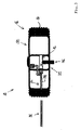
図1は、全体として参照符号10が付された自動車を示している。軸方向1は、自動車用ホイール18の回転軸3上にある。径方向2は、回転軸3に対して直交方向に延在する。自動車は、自動車用ホイール18のタイヤ16のタイヤ内腔14に圧力媒体を供給するコンプレッサー装置12を備える。
FIG. 1 shows a motor vehicle generally designated 10 . The axial direction 1 lies on the axis of rotation 3 of the
コンプレッサー装置12は、自動車用ホイール18に対して回転しないように設けられた圧縮室(図示せず)を有する。圧縮室およびタイヤ内腔14は、圧縮室からタイヤ内腔14に圧力媒体、例えば圧縮空気を送達するために、連通部22を介して接続される。
The
自動車10には、シール剤28を有するシール剤リザーバー26(図2を参照)を備えるタイヤシール装置24が割り当てられる。シール剤リザーバー26は、第1の接続部30および第2の接続部32を有する。第1の接続部30は、自動車10の修理されるタイヤ16のタイヤ内腔14に接続可能であるように構成される。第2の接続部32は、自動車に固定された圧力媒体源34に接続可能であるように構成される。
シール剤リザーバー26は、第1の接続部30が修理されるタイヤ16のタイヤ内腔14に連通するとともに、第2の接続部32が圧力媒体源34に連通すれる場合、圧力媒体によって、圧力媒体源34から修理されるタイヤ16のタイヤ内腔14にシール剤28が送達されるように構成される。
The
第1の接続部30は、修理されるタイヤ16のタイヤ内腔14との接続を可能にする可撓性導管部36を含む。第2の接続部32は、圧力媒体源34との接続を可能にする可撓性導管部38を含む。
The
少なくとも1つのバルブ40、42、44が設けられ、このバルブ40、42、44によって、第1の接続部30を修理されるタイヤ16のタイヤ内腔14から流体的に分離可能であるか、或いは、第2の接続部32を圧力媒体源34から流体的に分離可能である。この実施例では、シール剤リザーバーは、第1の接続部30においてバルブ40を備え、第2の接続部32においてバルブ42を備える。
At least one
バルブ40およびバルブ42は、それぞれチェックバルブとして形成される。さらに、第2の接続部32は、作業者によって制御可能なバルブ44(制御バルブ)を備えることができる。
修理されるタイヤ16のタイヤ内腔14は、自動車用ホイール18におけるホイール側接続部46を介して、シール剤リザーバー26の第1の接続部30に連通することができる。ホイール側接続部46とタイヤ内腔14との間の接続部は、少なくとも部分的に連通部22と共通して、圧縮室からタイヤ内腔14に流れることができる(図3を参照)。
The
修理されるタイヤ16のタイヤ内腔14は、上記の代わりに、自動車用ホイール18におけるホイール側接続部46を介して、シール剤リザーバー26の第1の接続部30に連通することができる。ホイール側接続部46とタイヤ内腔14との間の接続部は、(第1の)連通部22とは別個の更なる連通部48を介して、圧縮室からタイヤ内腔14に流れる(図1を参照)。
The
修理されるタイヤ16は、ホイールハブ受け部52を有するリム50上に配置され、ホイール側接続部46は、ホイールハブ受け部52の領域内またはホイールハブ受け部52に配置することができる。リム50は、ホイールハブ受け部52に対するカバー54を有し、ホイール側接続部46は、リム50におけるカバー54の取付け状態では隠れるように配置される。
The
ホイール側接続部46は、少なくとも部分的に、好ましくは専ら、交換可能な導管部56(図面では明確にするために別個に示されている)を介してタイヤ内腔14に連通する。交換可能な導管部56は、(取付け状態において)リム50に形成されたチャネル58内に少なくとも部分的に配置される。
The wheel-
圧力媒体源34は、圧力媒体貯蔵部として形成される。ここでは、圧力媒体が充填された自動車10の更なるタイヤ16’のタイヤ内腔14が、圧力媒体貯蔵部として機能する。
The pressure
この実施例では、コンプレッサー装置12は、自動車用ホイール18と、自動車用ホイール18が回転可能に支持されたホイールキャリア60との間の相対運動によって機械的に駆動可能である。コンプレッサー装置12を制御するために、電磁バルブ62および制御ユニット64が設けられる。
In this embodiment, the
示されていない実施形態において、コンプレッサー装置12は、電気的に駆動することができる。コンプレッサー装置12は、自動車側電源に接続することができる(図示せず)。電源は、自動車用ホイール18と、発電機18に回転可能に支持されたホイールキャリア60との間の相対運動によって、電流を発生させるように構成することができる。
In an embodiment not shown, the
図4は、コンプレッサー装置12の第1の実施形態を、側面図において詳細に示している。コンプレッサー装置12は、電気的に駆動され、ホイールハブ受け部52内に配置される。コンプレッサー装置12は、互いに対して回転しないように接続された第1のハブ側ハウジング部分130および第2のハブ側ハウジング部分132を備える。
FIG. 4 shows a first embodiment of the
図5において、図3のコンプレッサー装置が、線V-Vに沿って対応する矢印の方向に切断されて示されている。 In FIG. 5, the compressor arrangement of FIG. 3 is shown cut along line VV in the direction of the corresponding arrows.
ハブ側トランスミッション部分には参照符号134が付されている。図5では、コンプレッサー装置12は、複数のハブ側トランスミッション部分134を備えることが見て取れる。ハブ側トランスミッション部分134には、コンプレッサー部材138をなす環状ピストン136が接続される。
The hub side transmission portion is labeled 134 . In FIG. 5 it can be seen that the
環状ピストン136は、ダブルピストンとして構成され、第1の圧縮室140および第2の圧縮室142を画定する。第1の圧縮室140および第2の圧縮室142は、それぞれ環状空間として構成される。
ハブ側トランスミッション部材134は、駆動部側トランスミッション部分144と相互作用することができるように、駆動部側トランスミッション部分144に係合する。ハブ側トランスミッション部材134は、駆動部側トランスミッション部分144とともに、カムトランスミッションをなすトランスミッション装置145を形成する。ハブ側トランスミッション部分134は、第2のハブ側ハウジング部分132においてスロット形状の凹部146内に支持される。スロット形状の凹部146内に支持することにより、ハブ側トランスミッション部分134は、専ら回転軸3の方向に沿って第2のハブ側ハウジング部分132に対して並進運動することができる一方で、第2のハブ側ハウジング部分132およびコンプレッサー部材138に対する回転は阻止される。
Hub-
ハブ側トランスミッション部分134は、既に記載したように、駆動部側トランスミッション部分144に係合する。ここでは、それぞれのハブ側トランスミッション部分134の係合部148は、駆動部側トランスミッション部分144にあるカムトラック150内に係合する。カムトラック150は、円筒カム152の一実施形態である。
The hub
ハブ側ハウジング部分130、132の内部には、電気式駆動部154が配置される。電気式駆動部154は、第1の部分155が、ピン156によって、第1のハブ側ハウジング部分130に関して回転しないようになっており、第1のハブ側ハウジング部分130を介して第2のハブ側ハウジング部分132に間接的に接続される。電気式駆動部154の第2の部分158は、第1の部分155に対して回転可能かつ駆動部側トランスミッション部分144に関して回転しないように接続される。
An
図6において、図4、5のコンプレッサー装置12が、斜視断面図で示されている。図7において、コンプレッサー装置12は、図6と同様の斜視図で示され、ここでは、ハブ側トランスミッション部分134のうちの1つのみが示されている。環状ピストン136、第2のハブ側トランスミッション部分134および第1のハブ側ハウジング部分130は、それぞれ図示されていない。したがって、図7では、カムトラック150の経路が特に明確に見て取れる。
In FIG. 6 the
コンプレッサー装置12の動作時、電気式駆動部154の第2の部分158が第1の部分155に対して回転する。これにより、駆動部側トランスミッション部分144は、ハブ側ハウジング部分130、132に対して、またハブ側トランスミッション部分134に対して、図5の矢印160によって示されている回転において変位する。
During operation of
ハブ側トランスミッション部分134は、駆動部側トランスミッション部分144と相互作用することができるように、駆動部側トランスミッション部分144に係合する。この相互作用により、先程記載した回転相対運動160が、ハブ側トランスミッション部分134、ひいてはコンプレッサー部材138、すなわち環状ピストン136の振動並進運動162に変換される。振動並進運動により、第1の圧縮室140および第2の圧縮室142の容積が交互に減少、増大し、これにより、ここでは空気である圧縮室140、142内の圧力媒体が圧縮され、したがって、圧力下に置かれて送達される。空気、すなわち圧力媒体は、環状ピストン136の各送出工程において、タイヤ内腔14に開口するチェックバルブ166を介して、タイヤ内腔14に向かって圧力媒体導管を介して送出される。環状ピストン136の各吸引工程において、それぞれの圧縮室140、142に開口するチェックバルブ168が開き、空気が圧縮室140、142に流入することができる。
Hub
図9~図17は、コンプレッサー装置12の更なる一実施形態を詳細に示している。コンプレッサー装置12は、ホイールキャリア側とハブ側との間の回転相対運動によって機械的に駆動されるとともに、ホイールベアリングの領域に配置される。コンプレッサー装置12は、コンプレッサー部材218の径方向の動きを含む。
9-17 show a further embodiment of the
図9において、本発明に係るコンプレッサー装置12の第1の実施形態が詳細に示されている。コンプレッサー装置12は、第1のハウジング部分212および第2のハウジング部分214を備える。
In FIG. 9 a first embodiment of the
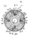
図10において、図2のコンプレッサー装置12の、線X-Xに沿った断面が示されている。コンプレッサー装置12は、ここでは全部で4つのハブ側圧縮室216を備えるが、参照符号はそのうちの2つにのみ付されている。
In FIG. 10 there is shown a cross-section along the line XX of the
圧縮室216のそれぞれは、ハブ側コンプレッサー部材218に割り当てられる。ハブ側コンプレッサー部材218も同様に、参照符号は2つのみ付されている。コンプレッサー装置12は、複数のトランスミッション220を備え、圧縮室216のそれぞれに、トランスミッション220が割り当てられている。トランスミッション220は、ここではそれぞれカムトランスミッション222として構成される。
Each of the
トランスミッション220は、それぞれハブ側トランスミッション部分224を備える。ハブ側トランスミッション部分224は、それぞれプランジャー出力部225によって形成される。コンプレッサー部材218は、プランジャー出力部225またはハブ側トランスミッション部分224と一体的に形成される。トランスミッション220のハブ側トランスミッション部分224は、コンプレッサー装置212のホイールキャリア側トランスミッション部分226とそれぞれ相互作用することができる。
図10から見て取れるように、コンプレッサー装置12は、ハブ側トランスミッション部分224のそれぞれと相互作用することができる1つのみのホイールキャリア側トランスミッション部分226を備える。ホイールキャリア側トランスミッション部分226は、外側カム輪郭230を有するディスクカム228として形成される。
As can be seen from FIG. 10, the
図10において、コンプレッサー装置212は、解放動作位置FLにおいて示されている。解放動作位置FLでは、ハブ側トランスミッション部分224は、ホイールキャリア側トランスミッション部分226と相互作用しない。
In FIG. 10 the
ハブ側トランスミッション部分224は、解放動作位置FLでは、図10に示されているように、ホイールキャリア側トランスミッション部分26の向きに関わらず、ホイールキャリア側トランスミッション部分26に接触することができない位置にあることが有利である。これは、ハブ側トランスミッション部分224のそれぞれに割り当てられた連結機構236によって達成される。連結機構236は、連結部材238をそれぞれ備える。図9に示されている解放動作位置において、連結部材238は、それぞれ係止位置240にある。連結部材238のこの係止位置240において、ハブ側トランスミッション部分224は、それぞれ、ホイールキャリア側トランスミッション部分226との相互作用、および、ここではまた接触が阻止される。
In the release operation position FL, the hub-
係止位置240において、それぞれの連結部材238の係止部242が、それぞれのハブ側トランスミッション部分224の停止部244に接する。また、停止部244は、ここでは、ハブ側トランスミッション部分224と一体的に形成されたコンプレッサー部材218に形成される。
In the locked
連結部材238は、ここでは鉛筆形に形成され、係止部242だけでなく、それぞれ解放部246および移行部248も備える。
The connecting
また、係止部242は、第1の直径を有する円筒形に形成され、解放部246は、第2の直径を有する円筒形に形成される。係止部242から解放部246への移行部248は、円錐台形状を有する。
Also, the locking
解放部246は、係止部242に対して径方向34の方向にオフセットされて配置されている。連結部材238が解放位置から係止位置240に動く場合、連結部材238に割り当てられたハブ側トランスミッション部分224は、ホイールキャリア側トランスミッション部分226と接触することができない位置に押される。
The
連結部材238は、ばね249を介して、それぞれ係止位置に付勢されている。連結部材238は、それぞれ、圧力媒体チャネル256を介して圧力媒体を作用させることによって、解放位置に移行可能である。
The connecting
圧力媒体チャネル256を介して圧力媒体を作用させることが中止されるとすぐに、連結部材238は、ばね付勢されているため、係止位置へと戻る。
As soon as the application of pressure medium via the
ここでは、ハブ側トランスミッション部分224またはコンプレッサー部材218は、径方向外方に、したがって、径方向内方にあるホイールキャリア側トランスミッション部分226から上昇した位置に押される。ここで、コンプレッサー装置212は、解放位置FLにある。円錐状に延在する移行部248によって、ハブ側トランスミッション部分224をこうして径方向外方に押すことが可能になり、解放位置から係止位置への移行が滑らかに徐々に行われる。
Here, the hub-
ハブ側トランスミッション部分224は、ここでは同様にばねを介して付勢されているため、連結部材38を付勢するばね249は、ハブ側トランスミッション部分を付勢するばねよりも高い強度で構成しなければならない。円筒状の移行部248と相互作用するこの付勢により、ハブ側トランスミッション部分224を上昇した位置に押すことが可能である。
Since the hub-
図12において、連結部材238の係止位置は、連結部材238のうちの1つにおいて特に良好に見て取れるように示されている。
In FIG. 12 the locking position of the connecting
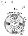
図14~図17は、様々な視点および断面において、作用動作位置ABにある図9~図13のコンプレッサー装置12を示している。
Figures 14-17 show the
図14において、ハブ側トランスミッション部材224が作用動作位置ABにおいてホイールキャリア側トランスミッション部材226に接触することが見て取れる。ハブ側トランスミッション部分224とホイールキャリア側トランスミッション部材226とのそれぞれの接触点には、参照符号250が付されている。
In FIG. 14 it can be seen that the hub
図14に見て取れるように、ハブ側トランスミッション部分224は、コンプレッサー部材218の並進運動を可能にするように、リニアガイド252においてそれぞれ支持されている。
As can be seen in FIG. 14, the hub-
図9~図17に示されている実施形態において、接触点250は、それぞれ径方向234に見てリニアガイド252と回転軸232との間にある。
In the embodiment shown in FIGS. 9-17, the
それぞれプランジャー出力部225をなすハブ側トランスミッション部分224は、カムディスク228またはホイールキャリア側トランスミッション部分226の外側輪郭230によって駆動可能である。
The hub-
図14~図17において作用動作位置ABで示されているようなコンプレッサー装置12の動作時、ハブ側部品は、ホイールキャリア側部品に対して回転運動する。ホイールキャリア側部品は車両に対して固定され、一方、ハブ側部品は車両に対して回転する。
During operation of the
図14の図は、ホイールキャリア側トランスミッション部分226の固定配置に対応し、一方、ハウジング部分212、214は、ハブ側トランスミッション部分224とともに回転軸232の周りに回転する。
The view of FIG. 14 corresponds to a fixed arrangement of the wheel carrier
また、ハブ側トランスミッション部分224の接触点250は、ディスクカム228の外側輪郭230に沿って摺動する。ディスクカム228の外側輪郭230が、回転軸232の周りに同心に延在する円形軌道の経路とは異なる回転軸232周りの経路を有することから、先程記載した回転運動は、ハブ側トランスミッション部分224、および、ひいてはハブ側トランスミッション部分224と一体的に形成されたコンプレッサー部材218の線形運動に変換される。
Also, the
したがって、コンプレッサー部材218は、径方向234の振動並進運動を行う。
Accordingly, the
この場合、圧縮室216の容積はそれぞれ減少、増大する。コンプレッサー装置212の圧縮室216には、圧縮室216の容積が低減したときに応じてタイヤ内腔27に送達される圧力媒体、ここでは空気が存在する。
In this case, the volume of
圧縮室216の容積が増大する場合、チェックバルブが閉じ、タイヤ内腔と圧縮室216との間の接続が中止される。反対に、チェックバルブが開くと、周囲空気を圧力媒体として圧縮室216に吸引することが可能である。
If the volume of
図12、16を比較すると、連結機構240の機能モードが特に良好に見て取れる。
A comparison of FIGS. 12 and 16 shows the functional mode of the
図16において、図示の連結部材238は、解放位置にある。コンプレッサー部材218は、径方向に自由に動くことができる。
In FIG. 16, the illustrated connecting
10 自動車
12 コンプレッサー装置
14 タイヤ内腔
16 タイヤ
18 自動車用ホイール
22 第1の連通部
24 タイヤシール装置
26 シール剤リザーバー
27 タイヤ内腔
28 シール剤
30 第1の接続部
32 第2の接続部
34 圧力媒体源
36 可撓性導管部
38 連結部材
40 バルブ
42 バルブ
44 バルブ
46 ホイール側接続部
48 連通部
50 リム
52 ホイールハブ受け部
54 カバー
56 導管部
58 チャネル
60 ホイールキャリア
62 電磁バルブ
64 制御ユニット
130 第1のハブ側ハウジング部分
132 第2のハブ側ハウジング部分
134 第2のハブ側トランスミッション部分
136 環状ピストン
138 コンプレッサー部材
140 第1の圧縮室
142 第2の圧縮室
144 駆動部側トランスミッション部分
145 トランスミッション装置
146 凹部
148 係合部
150 カムトラック
152 円筒カム
154 電気式駆動部
155 第1の部分
156 ピン
158 第2の部分
160 回転相対運動
162 振動並進運動
166 チェックバルブ
168 チェックバルブ
212 第1のハウジング部分
214 第2のハウジング部分
216 圧縮室
218 コンプレッサー部材
220 トランスミッション
222 カムトランスミッション
224 ハブ側トランスミッション部分
225 プランジャー出力部
226 ホイールキャリア側トランスミッション部分
228 ディスクカム
230 外側輪郭
232 回転軸
234 径方向
236 連結機構
238 連結部材
240 係止位置
242 係止部
244 停止部
246 解放部
248 移行部
250 接触点
252 リニアガイド
256 圧力媒体チャネル
10
Claims (14)
前記修理されるタイヤ(16)の前記タイヤ内腔(14)は、前記自動車用ホイール(18)におけるホイール側接続部(46)を介して、前記シール剤リザーバー(26)の前記第1の接続部(30)に連通し、ホイール側接続部(46)とタイヤ内腔(14)との間の接続部は、少なくとも部分的に前記連通部(22)と共通して、前記圧縮室から前記タイヤ内腔(14)に流れ、
前記修理されるタイヤ(16)は、ホイールハブ受け部(52)を有するリム(50)上に配置され、前記ホイール側接続部(46)は、前記ホイールハブ受け部(52)の領域内または前記ホイールハブ受け部(52)に配置される、
自動車。 A motor vehicle (10) comprising a compressor device (12) supplying pressure medium to a tire bore (14) of a tire (16) of a motor vehicle wheel (18), said compressor device (12) comprising a motor vehicle wheel. (18), said compression chamber and said tire lumen (14) being connected via communication (22) to said compression chamber for delivering pressure medium. A tire sealing device (24) is assigned to the vehicle (10), connected from a chamber to said tire lumen (14) and comprising a sealant reservoir (26) having a sealant (28), said sealant reservoir (26) has a first connection (30) and a second connection (32), said first connection (30) connecting to a tire to be repaired (16) of said motor vehicle (10). said second connection (32) is adapted to be connectable to a pressure medium source (34) fixed to the motor vehicle, said The sealant reservoir (26) communicates the first connection (30) with the tire lumen (14) of the tire to be repaired (16) and the second connection (32) communicates with the pressure. When in communication with a media source (34), pressure media from the pressure media source (34) delivers the sealant (28) to the tire lumen (14) of the tire to be repaired (16). configured to
The tire bore (14) of the tire to be repaired (16) is connected to the first connection of the sealant reservoir (26) via a wheel-side connection (46) in the motor vehicle wheel (18). The connection between the wheel-side connection (46) and the tire bore (14) communicates with the portion (30) and is at least partially in common with the communication portion (22) from the compression chamber to the flowing into the tire lumen (14);
Said tire (16) to be repaired is placed on a rim (50) having a wheel hub receptacle (52), said wheel side connection (46) being in the area of said wheel hub receptacle (52) or disposed in the wheel hub receiving portion (52);
Automobile.
Applications Claiming Priority (3)
| Application Number | Priority Date | Filing Date | Title |
|---|---|---|---|
| DE102016122735.8A DE102016122735A1 (en) | 2016-11-24 | 2016-11-24 | Motor vehicle with a compressor arrangement |
| DE102016122735.8 | 2016-11-24 | ||
| PCT/EP2017/080384 WO2018096108A1 (en) | 2016-11-24 | 2017-11-24 | Motor vehicle comprising a compressor assembly |
Publications (2)
| Publication Number | Publication Date |
|---|---|
| JP2019535585A JP2019535585A (en) | 2019-12-12 |
| JP7127024B2 true JP7127024B2 (en) | 2022-08-29 |
Family
ID=60997416
Family Applications (1)
| Application Number | Title | Priority Date | Filing Date |
|---|---|---|---|
| JP2019527844A Active JP7127024B2 (en) | 2016-11-24 | 2017-11-24 | Automobile equipped with a compressor device |
Country Status (8)
| Country | Link |
|---|---|
| US (1) | US11370189B2 (en) |
| EP (1) | EP3544830B1 (en) |
| JP (1) | JP7127024B2 (en) |
| KR (1) | KR102516999B1 (en) |
| CN (1) | CN110691704B (en) |
| BR (1) | BR112019010516B1 (en) |
| DE (1) | DE102016122735A1 (en) |
| WO (1) | WO2018096108A1 (en) |
Families Citing this family (19)
| Publication number | Priority date | Publication date | Assignee | Title |
|---|---|---|---|---|
| US11453258B2 (en) | 2013-03-12 | 2022-09-27 | Aperia Technologies, Inc. | System for tire inflation |
| DE102016122738A1 (en) | 2016-11-24 | 2018-05-24 | Kt Projektentwicklungs-Gmbh | Compressor arrangement with radial piston |
| DE102016122735A1 (en) | 2016-11-24 | 2018-05-24 | Kt Projektentwicklungs-Gmbh | Motor vehicle with a compressor arrangement |
| DE102016122736A1 (en) * | 2016-11-24 | 2018-05-24 | Kt Projektentwicklungs-Gmbh | Vehicle with compressor arrangement |
| DE102016122739A1 (en) | 2016-11-24 | 2018-05-24 | Kt Projektentwicklungs-Gmbh | Compressor arrangement with bead cylinder curve |
| DE102016122737A1 (en) | 2016-11-24 | 2018-05-24 | Kt Projektentwicklungs-Gmbh | compressor assembly |
| DE102017106805A1 (en) | 2017-03-03 | 2018-09-06 | Kt Projektentwicklungs-Gmbh | Compressor arrangement with magnetic coupling |
| US12059930B1 (en) | 2017-07-31 | 2024-08-13 | Aperia Technologies, Inc. | System and method for automatic pressure management |
| US10406869B2 (en) | 2017-11-10 | 2019-09-10 | Aperia Technologies, Inc. | Inflation system |
| US12145332B2 (en) | 2018-06-21 | 2024-11-19 | Illinois Tool Works Inc. | Vehicle tire inflation compressor for powered data ports |
| US10933844B2 (en) * | 2018-06-21 | 2021-03-02 | Illinois Tool Works Inc. | Vehicle tire inflation compressor for powered data ports |
| WO2020112686A1 (en) | 2018-11-27 | 2020-06-04 | Aperia Technologies, Inc. | Hub-integrated inflation system |
| US12344047B2 (en) * | 2020-10-29 | 2025-07-01 | William Pamphile | Automatic air tire technology system |
| DE102021101463A1 (en) * | 2021-01-25 | 2022-07-28 | Illinois Tool Works Inc. | TIRE REPAIR KIT AND METHOD FOR INFLating AND/OR SEALING A TIRE |
| IT202100007853A1 (en) * | 2021-03-30 | 2022-09-30 | Francesco Iadecola | SYSTEM FOR THE AUTOMATIC REPAIR OF PUNCTURED TIRES, RELATIVE KIT AND REPAIR METHOD |
| DE102021121488A1 (en) * | 2021-08-19 | 2023-02-23 | Aircom Automotive Sp. z o.o. Sp. k. | Compressed air supply system, in particular for supplying air for tires of a motor vehicle |
| KR102743339B1 (en) | 2022-12-08 | 2024-12-17 | 케이티 프로젝텐트윅렁스-게엠베하 | Tire repair device for attachment to a vehicle wheel |
| DE102023210052A1 (en) * | 2023-10-13 | 2025-04-17 | Contitech Deutschland Gmbh | Small vehicle, preferably cargo bike, with pneumatic tires |
| CN119795800A (en) * | 2025-02-21 | 2025-04-11 | 浙江吉利控股集团有限公司 | Intelligent tire inflation system based on EMB and control method, device and vehicle thereof |
Citations (3)
| Publication number | Priority date | Publication date | Assignee | Title |
|---|---|---|---|---|
| JP2007039013A (en) | 2005-06-27 | 2007-02-15 | Toyota Motor Corp | Pressure generator |
| WO2015075655A1 (en) | 2013-11-22 | 2015-05-28 | NDLOVU, Raymond | Device for controlling the pressure in a vehicle tyre |
| WO2015136006A2 (en) | 2014-03-11 | 2015-09-17 | TSIBERIDOU, Julia | Pressurized-medium supply device, wheel unit having a pressurized-medium supply device, and distributed system for supplying pressurized medium |
Family Cites Families (70)
| Publication number | Priority date | Publication date | Assignee | Title |
|---|---|---|---|---|
| US655797A (en) | 1899-09-28 | 1900-08-14 | Walter M Reason | Bicycle-pump. |
| US652997A (en) | 1899-11-27 | 1900-07-03 | Albert L Crandall | Bicycle-pump. |
| US648408A (en) | 1900-03-14 | 1900-05-01 | William Hayes | Self-pumping pneumatic vehicle-wheel. |
| US797447A (en) | 1904-09-17 | 1905-08-15 | Bradford Merry | Bicycle-pump. |
| US1713899A (en) * | 1926-10-07 | 1929-05-21 | Raymond A Gray | Tire inflater |
| US2317636A (en) * | 1941-02-24 | 1943-04-27 | Clark W Parker | Dual tire inflater |
| US2506677A (en) | 1944-09-28 | 1950-05-09 | Mckenna Denis | Vehicle wheel |
| FR1324352A (en) | 1962-03-06 | 1963-04-19 | Kleber Colombes | Device for ballasting tires with water |
| CN1003383B (en) | 1985-06-29 | 1989-02-22 | 徐龙生 | Automatic aerator |
| CN86105562A (en) | 1986-07-12 | 1988-02-03 | 丁定藩 | Automatic tire inflation device |
| FR2618102B1 (en) | 1987-07-15 | 1990-02-16 | Michelin & Cie | INFLATION OF A ROTATING TIRE |
| DE4133039A1 (en) | 1991-10-06 | 1993-04-08 | Helmut Piller | ROLLING ROTATION POWERED VEHICLE TIRE FUEL AND PRESSURE CONTROL SYSTEM |
| US5325902A (en) | 1992-06-19 | 1994-07-05 | Loewe Richard T | Automatic tire pressure monitor and inflation system |
| CN2188661Y (en) | 1993-12-30 | 1995-02-01 | 冻慧安 | Automatic micro-pressure-regulating pump |
| US5505080A (en) | 1994-05-12 | 1996-04-09 | Tellair Corporation | Tire pressure management system |
| CN2202665Y (en) | 1994-09-29 | 1995-07-05 | 麦永光 | Automatic pressure-adjustable miniature inflator for bicycle |
| WO1997002961A1 (en) | 1995-07-10 | 1997-01-30 | Cycloid Company | Tire pressurizing and regulating apparatus |
| CN2252128Y (en) | 1996-01-23 | 1997-04-16 | 张方 | Damper with floating pump supply air |
| JPH11139118A (en) | 1997-11-07 | 1999-05-25 | Sumitomo Electric Ind Ltd | Tire pressure adjusting device |
| WO2001028787A1 (en) * | 1999-10-21 | 2001-04-26 | Czarno Yanush | Wheel system including automatic tire repair |
| CZ20022938A3 (en) | 2001-02-16 | 2003-02-12 | Continental Ag | Method of filling an object and apparatus for making the same |
| US6345650B1 (en) * | 2001-05-22 | 2002-02-12 | Robert W. Paasch | Tire repair device and method |
| WO2004087442A1 (en) | 2003-03-28 | 2004-10-14 | Takaji Nakano | Automatic air-feeding mechanism for pneumatic tire |
| US6994136B2 (en) | 2003-05-02 | 2006-02-07 | Arvinmeritor Technology, Llc | Wheel end tire air pump |
| DE102004042911A1 (en) | 2004-09-02 | 2006-03-09 | Michael Stehle | Device for dispensing air and / or tire sealant |
| JP4563767B2 (en) | 2004-10-12 | 2010-10-13 | 株式会社ブリヂストン | Puncture first aid device and air circuit for puncture first aid |
| US7784513B2 (en) | 2004-11-12 | 2010-08-31 | Richard Thomas Loewe | Tire pressure maintenance device |
| EP1817180B1 (en) * | 2004-11-12 | 2011-08-17 | Richard Loewe | Tire pressure maintenance device |
| JP4626363B2 (en) | 2005-03-31 | 2011-02-09 | トヨタ自動車株式会社 | Motion conversion mechanism |
| DE102005019766B4 (en) * | 2005-04-28 | 2019-07-11 | Continental Reifen Deutschland Gmbh | Device for sealing and inflating inflatable objects |
| JP4673134B2 (en) | 2005-06-02 | 2011-04-20 | 株式会社ブリヂストン | Sealant storage and injection container |
| DE202005017071U1 (en) | 2005-10-28 | 2007-03-15 | Stehle, Michael | Filling system for sealing and inflating tires |
| CN101313162A (en) | 2005-12-15 | 2008-11-26 | 伊利诺斯工具制品有限公司 | Air damper |
| JP4529899B2 (en) | 2005-12-28 | 2010-08-25 | トヨタ自動車株式会社 | Air supply device |
| JP4407672B2 (en) * | 2006-06-30 | 2010-02-03 | トヨタ自動車株式会社 | Tire pressure control device |
| EP1878594B1 (en) | 2006-07-11 | 2009-03-04 | Aktiebolaget SKF | A hub-bearing assembly allowing pressurized air to be supplied to the tyre of a vehicle wheel |
| FR2904048B1 (en) | 2006-07-19 | 2012-12-14 | Snecma | COMBUSTION CHAMBER WALL VENTILATION SYSTEM IN TURBOMACHINE |
| CN201061989Y (en) | 2007-03-21 | 2008-05-21 | 陈旭颖 | Air pump equipped on running wheel and capable of realizing auto-inflation for inner tube |
| CN201082666Y (en) | 2007-09-12 | 2008-07-09 | 陈贺章 | Tyre explosion-proof device |
| US8020588B2 (en) | 2008-09-11 | 2011-09-20 | Min-Hsieng Wang | Tire repair solution can |
| GB0910491D0 (en) * | 2009-06-17 | 2009-07-29 | Sealy Mark | Tyre inflation device |
| US8794355B2 (en) | 2009-10-07 | 2014-08-05 | Longyear Tm, Inc. | Driven latch mechanism |
| CN101696681A (en) | 2009-10-21 | 2010-04-21 | 浙江鸿友压缩机制造有限公司 | Cam-restricting reciprocating piston type compressor |
| DE102009060272B4 (en) | 2009-12-23 | 2022-11-10 | Sumitomo Rubber Industries Ltd. | Device for introducing air and/or sealant into a tire |
| DE102010010361B4 (en) | 2010-03-05 | 2020-12-10 | Sumitomo Rubber Industries, Ltd. | Device for introducing air and / or sealing agent into a tire |
| BR112013012298B1 (en) | 2010-11-19 | 2020-04-28 | Equalaire Systems Inc | tire management system and method for managing tire pressure |
| WO2012137292A1 (en) | 2011-04-04 | 2012-10-11 | トヨタ自動車株式会社 | Vehicle oil pump |
| US9457772B2 (en) * | 2011-08-18 | 2016-10-04 | Paasch Products, Inc. | Inflation apparatus and methods |
| CN202439521U (en) | 2012-02-26 | 2012-09-19 | 张卫 | Automatic inflator pump |
| BR112014022974B1 (en) | 2012-03-20 | 2021-08-17 | Aperia Technologies | TIRE INFLATION SYSTEM |
| US9046176B2 (en) | 2012-04-16 | 2015-06-02 | Ntn Corporation | Hydraulic auto-tensioner |
| WO2014009822A1 (en) | 2012-07-13 | 2014-01-16 | Bacon, Brian | Device for controlling the pressure in a vehicle tyre |
| US20140096881A1 (en) | 2012-10-08 | 2014-04-10 | Richard Loewe | Tire pressure maintenance device |
| CN103465736A (en) | 2013-07-09 | 2013-12-25 | 天津富士达集团有限公司 | Bicycle automatic pressure regulating micro inflator pump |
| GB201313622D0 (en) | 2013-07-30 | 2013-09-11 | Jaguar Land Rover Ltd | Vehicle wheel assembly |
| US9428016B2 (en) | 2013-10-11 | 2016-08-30 | Arvinmeritor Technology, Llc | Tire inflation system with axle driven pump |
| WO2015063679A1 (en) | 2013-10-28 | 2015-05-07 | NDLOVU, Raymond | Device for controlling the pressure in a vehicle tyre |
| JP2017500238A (en) | 2013-11-22 | 2017-01-05 | プレッシャーライト(ピーティーワイ)エルティーディー | Device for controlling vehicle tire pressure |
| DE202014010520U1 (en) | 2014-03-27 | 2015-11-13 | Walter Wagatha | Wheel with a fluid-filled tire and a device for adjusting the tire pressure and equipped with such wheels bike, motor vehicle or aircraft |
| DE102015203972A1 (en) | 2015-03-05 | 2016-09-08 | Continental Reifen Deutschland Gmbh | Portable repair kit |
| CN205044451U (en) | 2015-04-29 | 2016-02-24 | 西南科技大学 | Automatic inflate proper motion wheel with pressurize |
| CN107530991A (en) * | 2015-05-05 | 2018-01-02 | 乔纳森·史密斯 | Wheel accessories and assembly method thereof |
| US11225111B2 (en) | 2015-09-16 | 2022-01-18 | Illinois Tool Works Inc. | Tire pressure control system and components |
| DE102015115642A1 (en) * | 2015-09-16 | 2017-03-16 | Illinois Tool Works Inc. | Distributed system for pressure medium supply, pressure medium supply device and vehicle wheel |
| US20170113500A1 (en) | 2015-10-27 | 2017-04-27 | The Goodyear Tire & Rubber Company | On-wheel air maintenance system |
| DE102016122739A1 (en) | 2016-11-24 | 2018-05-24 | Kt Projektentwicklungs-Gmbh | Compressor arrangement with bead cylinder curve |
| DE102016122735A1 (en) | 2016-11-24 | 2018-05-24 | Kt Projektentwicklungs-Gmbh | Motor vehicle with a compressor arrangement |
| DE102016122737A1 (en) | 2016-11-24 | 2018-05-24 | Kt Projektentwicklungs-Gmbh | compressor assembly |
| DE102016122736A1 (en) | 2016-11-24 | 2018-05-24 | Kt Projektentwicklungs-Gmbh | Vehicle with compressor arrangement |
| DE102016122738A1 (en) | 2016-11-24 | 2018-05-24 | Kt Projektentwicklungs-Gmbh | Compressor arrangement with radial piston |
-
2016
- 2016-11-24 DE DE102016122735.8A patent/DE102016122735A1/en not_active Withdrawn
-
2017
- 2017-11-24 BR BR112019010516-6A patent/BR112019010516B1/en active IP Right Grant
- 2017-11-24 EP EP17829927.7A patent/EP3544830B1/en active Active
- 2017-11-24 KR KR1020197017538A patent/KR102516999B1/en active Active
- 2017-11-24 JP JP2019527844A patent/JP7127024B2/en active Active
- 2017-11-24 WO PCT/EP2017/080384 patent/WO2018096108A1/en not_active Ceased
- 2017-11-24 US US16/463,188 patent/US11370189B2/en active Active
- 2017-11-24 CN CN201780083843.4A patent/CN110691704B/en active Active
Patent Citations (3)
| Publication number | Priority date | Publication date | Assignee | Title |
|---|---|---|---|---|
| JP2007039013A (en) | 2005-06-27 | 2007-02-15 | Toyota Motor Corp | Pressure generator |
| WO2015075655A1 (en) | 2013-11-22 | 2015-05-28 | NDLOVU, Raymond | Device for controlling the pressure in a vehicle tyre |
| WO2015136006A2 (en) | 2014-03-11 | 2015-09-17 | TSIBERIDOU, Julia | Pressurized-medium supply device, wheel unit having a pressurized-medium supply device, and distributed system for supplying pressurized medium |
Also Published As
| Publication number | Publication date |
|---|---|
| EP3544830B1 (en) | 2021-07-28 |
| WO2018096108A1 (en) | 2018-05-31 |
| CN110691704B (en) | 2022-04-15 |
| JP2019535585A (en) | 2019-12-12 |
| DE102016122735A1 (en) | 2018-05-24 |
| EP3544830A1 (en) | 2019-10-02 |
| CN110691704A (en) | 2020-01-14 |
| KR20190126762A (en) | 2019-11-12 |
| US11370189B2 (en) | 2022-06-28 |
| US20200070450A1 (en) | 2020-03-05 |
| KR102516999B1 (en) | 2023-03-31 |
| BR112019010516A2 (en) | 2019-10-01 |
| BR112019010516B1 (en) | 2022-07-12 |
Similar Documents
| Publication | Publication Date | Title |
|---|---|---|
| KR102516999B1 (en) | Vehicles Including the Compressor Assembly | |
| CN108496002B (en) | Tire Pressure Control Systems and Components | |
| US6994136B2 (en) | Wheel end tire air pump | |
| EP2468540B1 (en) | Pump and actuator assembly for a self-inflating tire | |
| KR102469928B1 (en) | Vehicles with Compressor Assembly | |
| CN105705348B (en) | Automatic truck component tire inflation system with dual pumps | |
| JP7114587B2 (en) | Compressor device with raised cylindrical cam | |
| JP7084922B2 (en) | Compressor device with radial piston | |
| JP7145153B2 (en) | Compressor device | |
| JP2015113001A (en) | Valve control device | |
| JP2002103935A (en) | Air filling or air releasing device for tire |
Legal Events
| Date | Code | Title | Description |
|---|---|---|---|
| A621 | Written request for application examination |
Free format text: JAPANESE INTERMEDIATE CODE: A621 Effective date: 20201106 |
|
| A977 | Report on retrieval |
Free format text: JAPANESE INTERMEDIATE CODE: A971007 Effective date: 20211116 |
|
| A131 | Notification of reasons for refusal |
Free format text: JAPANESE INTERMEDIATE CODE: A131 Effective date: 20220104 |
|
| A521 | Request for written amendment filed |
Free format text: JAPANESE INTERMEDIATE CODE: A523 Effective date: 20220311 |
|
| TRDD | Decision of grant or rejection written | ||
| A01 | Written decision to grant a patent or to grant a registration (utility model) |
Free format text: JAPANESE INTERMEDIATE CODE: A01 Effective date: 20220802 |
|
| A61 | First payment of annual fees (during grant procedure) |
Free format text: JAPANESE INTERMEDIATE CODE: A61 Effective date: 20220817 |
|
| R150 | Certificate of patent or registration of utility model |
Ref document number: 7127024 Country of ref document: JP Free format text: JAPANESE INTERMEDIATE CODE: R150 |
|
| R250 | Receipt of annual fees |
Free format text: JAPANESE INTERMEDIATE CODE: R250 |