JP7125014B2 - Keyboard instrument and manufacturing method thereof - Google Patents

Keyboard instrument and manufacturing method thereof Download PDF

Info

Publication number
JP7125014B2
JP7125014B2 JP2019132033A JP2019132033A JP7125014B2 JP 7125014 B2 JP7125014 B2 JP 7125014B2 JP 2019132033 A JP2019132033 A JP 2019132033A JP 2019132033 A JP2019132033 A JP 2019132033A JP 7125014 B2 JP7125014 B2 JP 7125014B2
Authority
JP
Japan
Prior art keywords
key
connecting portion
pair
case
white
Prior art date
Legal status (The legal status is an assumption and is not a legal conclusion. Google has not performed a legal analysis and makes no representation as to the accuracy of the status listed.)
Active
Application number
JP2019132033A
Other languages
Japanese (ja)
Other versions
JP2021018266A5 (en
JP2021018266A (en
Inventor
弘和 谷口
淳 大城
大輔 能登
Current Assignee (The listed assignees may be inaccurate. Google has not performed a legal analysis and makes no representation or warranty as to the accuracy of the list.)
Casio Computer Co Ltd
Original Assignee
Casio Computer Co Ltd
Priority date (The priority date is an assumption and is not a legal conclusion. Google has not performed a legal analysis and makes no representation as to the accuracy of the date listed.)
Filing date
Publication date
Application filed by Casio Computer Co Ltd filed Critical Casio Computer Co Ltd
Priority to JP2019132033A priority Critical patent/JP7125014B2/en
Priority to CN202010685012.8A priority patent/CN112242130A/en
Priority to US16/931,270 priority patent/US11335308B2/en
Publication of JP2021018266A publication Critical patent/JP2021018266A/en
Publication of JP2021018266A5 publication Critical patent/JP2021018266A5/ja
Priority to JP2022126902A priority patent/JP7400897B2/en
Application granted granted Critical
Publication of JP7125014B2 publication Critical patent/JP7125014B2/en
Active legal-status Critical Current
Anticipated expiration legal-status Critical

Links

Images

Classifications

    • GPHYSICS
    • G10MUSICAL INSTRUMENTS; ACOUSTICS
    • G10HELECTROPHONIC MUSICAL INSTRUMENTS; INSTRUMENTS IN WHICH THE TONES ARE GENERATED BY ELECTROMECHANICAL MEANS OR ELECTRONIC GENERATORS, OR IN WHICH THE TONES ARE SYNTHESISED FROM A DATA STORE
    • G10H1/00Details of electrophonic musical instruments
    • G10H1/32Constructional details
    • G10H1/34Switch arrangements, e.g. keyboards or mechanical switches specially adapted for electrophonic musical instruments
    • G10H1/344Structural association with individual keys

Description

この発明は、鍵盤楽器およびその製造方法に関する。 The present invention relates to a keyboard instrument and a manufacturing method thereof.

例えば、鍵盤楽器においては、特許文献1に記載れているように、複数の鍵が連結された鍵連結部を有する鍵ユニットを下ケースと上ケースとの間に取り付ける際に、鍵連結部を下ケースの台座部と上ケースのボスとの間に挟み付けた状態で、台座部とボスとをねじによって締結する構造のものが知られている。 For example, in a keyboard instrument, as described in Patent Document 1, when attaching a key unit having a key connecting portion in which a plurality of keys are connected between a lower case and an upper case, the key connecting portion is attached. A structure is known in which the pedestal of the lower case and the boss of the upper case are fastened together with screws while being sandwiched between the pedestal of the lower case and the boss of the upper case.

特開2011-17942号公報JP 2011-17942 A

このような鍵盤楽器では、鍵ユニットの鍵連結部を下ケースの台座部と上ケースのボスとの間に挟み付けて、台座部とボスとをねじによって締結する構造であるから、鍵ユニットにおけるねじによって締結された部分と、その部分から離れた部分と、では高さ方向の位置ずれが生じ易く、良好に押鍵できるように鍵ユニットを固定することが難しいという問題がある。 In such a keyboard instrument, the key connecting portion of the key unit is sandwiched between the pedestal portion of the lower case and the boss of the upper case, and the pedestal portion and the boss are fastened with screws. There is a problem that it is difficult to fix the key unit so that the portion fastened by the screw and the portion separated from the screw are likely to be misaligned in the height direction, so that the keys can be depressed well.

この発明が解決しようとする課題は、鍵ユニットを良好に固定することができる鍵盤楽器およびその製造方法を提供することである。 SUMMARY OF THE INVENTION An object of the present invention is to provide a keyboard instrument in which a key unit can be satisfactorily fixed, and a manufacturing method thereof.

この発明の一態様は、複数の鍵が連結されている鍵連結部を有する鍵ユニットと、台座部と、前記台座部の上側に前記台座部から突出して配置された一対のリブである保持部と、を有する下ケースと、を備え、前記鍵連結部には嵌合突起が設けられており、当該嵌合突起が前記一対のリブの間に嵌合されている、鍵盤楽器である。 According to one aspect of the present invention, a key unit having a key connecting portion to which a plurality of keys are connected, a pedestal , and a holding portion that is a pair of ribs arranged on the upper side of the pedestal so as to protrude from the pedestal. and a lower case having and, wherein the key connecting portion is provided with a fitting projection, and the fitting projection is fitted between the pair of ribs .

また、この発明の他の一態様は、鍵ユニットにおける複数の鍵が連結されている鍵連結部を下ケースの台座部上に配置された保持部に載置させて、前記鍵連結部の嵌合凸部を前記保持部の嵌合凹部に嵌合させる第1の工程と、前記鍵連結部に設けられた挿入孔を通して締結部材を前記保持部の取付部に締結させる第2の工程と、を備えている鍵盤楽器の製造方法である。 According to another aspect of the present invention, a key connecting portion to which a plurality of keys are connected in a key unit is placed on a holding portion arranged on a pedestal portion of a lower case, and the key connecting portion is fitted. a first step of fitting a mating projection into a fitting recess of the holding portion; a second step of fastening a fastening member to the mounting portion of the holding portion through an insertion hole provided in the key connecting portion; A method for manufacturing a keyboard instrument comprising

この発明によれば、鍵ユニットを良好に固定することができる。 According to this invention, the key unit can be satisfactorily fixed.

この発明を適用した鍵盤楽器の一実施形態を示した斜視図である。1 is a perspective view showing an embodiment of a keyboard instrument to which the invention is applied; FIG. 図1に示された鍵盤楽器のA-A矢視における拡大断面図である。FIG. 2 is an enlarged cross-sectional view of the keyboard instrument shown in FIG. 1 taken along line AA. 図1に示された鍵盤楽器の鍵ユニットの要部を分解して示した拡大斜視図である。FIG. 2 is an enlarged perspective view showing an exploded main part of the key unit of the keyboard instrument shown in FIG. 1; 図3に示された鍵ユニットを裏面側から見た拡大斜視図である。FIG. 4 is an enlarged perspective view of the key unit shown in FIG. 3 as seen from the back side; 図1に示された鍵盤楽器において、下ケースと鍵ユニットとの要部を分解して示した拡大斜視図である。2 is an enlarged perspective view showing an exploded main part of a lower case and a key unit in the keyboard instrument shown in FIG. 1; FIG. 図5に示された鍵盤楽器のB-B矢視において、鍵ユニットを下ケースに取り付けた状態を示した拡大断面図である。FIG. 6 is an enlarged cross-sectional view of the keyboard instrument shown in FIG. 5 taken along line BB, showing a state in which the key unit is attached to the lower case; 図6に示された鍵盤楽器において、下ケースに鍵ユニットを取り付ける状態を分解して示した拡大断面図である。FIG. 7 is an enlarged cross-sectional view showing an exploded state in which the key unit is attached to the lower case in the keyboard instrument shown in FIG. 6; 図6に示された鍵盤楽器の要部を示した拡大断面図である。7 is an enlarged cross-sectional view showing a main part of the keyboard instrument shown in FIG. 6; FIG. 図5に示された鍵盤楽器のC-C矢視において、下ケースに鍵ユニットを取り付けた状態を示した拡大断面図である。6 is an enlarged cross-sectional view of the keyboard instrument shown in FIG. 5 taken along line CC, showing a state in which the key unit is attached to the lower case; FIG. 図1に示された鍵盤楽器のD-D矢視における拡大断面図である。FIG. 2 is an enlarged cross-sectional view of the keyboard instrument shown in FIG. 1 taken along line DD. 図10に示された鍵盤楽器の要部を示した拡大断面図である。11 is an enlarged cross-sectional view showing a main part of the keyboard instrument shown in FIG. 10; FIG. 図10に示された鍵盤楽器において、下ケースに上ケースを取り付ける状態を分解して示した拡大断面図である。FIG. 11 is an enlarged cross-sectional view showing an exploded state in which the upper case is attached to the lower case in the keyboard instrument shown in FIG. 10;

以下、図1~図12を参照して、この発明を適用した鍵盤楽器の一実施形態について説明する。
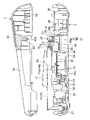
この鍵盤楽器は、図1および図2に示すように、楽器ケース1を備えている。この楽器ケース1は、下ケース2と上ケース3とを備えている。下ケース2は、上側が開放された横方向に長いほぼ箱状に形成されている。上ケース3は、下側が開放され、且つ両側部を除いて前側に開放された開口部3aが設けられ、下ケース2上に重なって配置されるようになっている。この上ケース3の上面には、操作パネル3bが設けられている。
An embodiment of a keyboard instrument to which the present invention is applied will be described below with reference to FIGS. 1 to 12. FIG.
This keyboard instrument includes a musical instrument case 1, as shown in FIGS. This musical instrument case 1 comprises a lower case 2 and an upper case 3. The lower case 2 is formed in a substantially box-like shape with an open upper side and a laterally elongated shape. The upper case 3 is open at the bottom and provided with an opening 3a that is open to the front except for both sides, and is arranged to overlap the lower case 2. As shown in FIG. An operation panel 3b is provided on the upper surface of the upper case 3. As shown in FIG.

この楽器ケース1には、図1および図2に示すように、鍵ユニット4、表示部5、複数のスイッチ6、および複数のスピーカ部7が設けられている。表示部5は、上ケース3の操作パネル3bに設けられた平面型の表示パネルであり、演奏に必要な情報を表示するようになっている。複数のスイッチ6は、上ケース3の操作パネル3bに設けられて、音量や音色などの楽音を調整するためのものである。複数のスピーカ部7は、上ケース3内における後部両側に設けられ、鍵ユニット4の押鍵操作に応じて楽音を発生するものである。 The musical instrument case 1 is provided with a key unit 4, a display section 5, a plurality of switches 6, and a plurality of speaker sections 7, as shown in FIGS. The display unit 5 is a flat display panel provided on the operation panel 3b of the upper case 3, and displays information necessary for performance. A plurality of switches 6 are provided on the operation panel 3b of the upper case 3 and are used to adjust musical tones such as volume and timbre. A plurality of speaker sections 7 are provided on both sides of the rear portion of the upper case 3, and generate musical sounds in response to key depression operations of the key unit 4. As shown in FIG.

鍵ユニット4は、図1~図4に示すように、第1の白鍵ユニット8、第2の白鍵ユニット9、および黒鍵ユニット10を備え、上ケース3の開口部3aから上方に露出した状態で、楽器ケース1内に配置されている。第1の白鍵ユニット8は、所定の間隔で配列された複数の第1白鍵11がそれぞれ第1屈曲部12によって第1鍵連結部13に押鍵操作可能に連結されたものであり、これらが合成樹脂によって一体に形成されている。 1 to 4, the key unit 4 includes a first white key unit 8, a second white key unit 9, and a black key unit 10, and is exposed upward through the opening 3a of the upper case 3. It is arranged in the musical instrument case 1 in a state where it is closed. The first white key unit 8 includes a plurality of first white keys 11 arranged at predetermined intervals, each of which is connected to a first key connecting portion 13 by a first bent portion 12 so as to be depressible. These are integrally formed of synthetic resin.

この場合、第1鍵連結部13は、図3および図4に示すように、複数の第1白鍵11の配列方向に沿って長い帯板状をなしている。複数の第1屈曲部12は、各一端部が複数の第1白鍵11の各後端部における上部に連結され、各他端部が第1鍵連結部13に連結され、これらの各他端部を支点として上下方向に撓み変形することにより、複数の第1白鍵11を上下方向に揺動させるようになっている。 In this case, as shown in FIGS. 3 and 4, the first key connecting portion 13 has a long strip shape along the direction in which the plurality of first white keys 11 are arranged. Each of the plurality of first bent portions 12 has one end connected to the upper portion of each rear end of each of the plurality of first white keys 11, and the other end connected to the first key connecting portion 13. The plurality of first white keys 11 are oscillated vertically by bending and deforming in the vertical direction with the end portion as a fulcrum.

第2の白鍵ユニット9は、図3および図4に示すように、所定の間隔で配列された第1の白鍵ユニット8における複数の第1白鍵11間にそれぞれ配置される複数の第2白鍵14を備えている。この第2の白鍵ユニット9は、第1の白鍵ユニット8と同様、複数の第2白鍵14がそれぞれ第2屈曲部15によって第2鍵連結部16に押鍵操作可能に連結されたものであり、これらが合成樹脂によって一体に形成されている。 As shown in FIGS. 3 and 4, the second white key unit 9 includes a plurality of first white keys 11 arranged between the first white keys 11 of the first white key unit 8 arranged at predetermined intervals. 2 white keys 14 are provided. As in the first white key unit 8, the second white key unit 9 has a plurality of second white keys 14 each connected to a second key connecting portion 16 by a second bending portion 15 so as to be capable of being pressed. , which are integrally formed of synthetic resin.

この場合にも、第2鍵連結部16は、図3および図4に示すように、第1鍵連結部13と同様、複数の第2白鍵14の配列方向に沿って長い帯板状をなしている。複数の第2屈曲部15は、各一端部が複数の第2白鍵14の各後端部における下部に連結され、各他端部が第2鍵連結部16に連結され、これらの各他端部を支点として上下方向に撓み変形することにより、複数の第2白鍵14を上下方向に揺動させるようになっている。 In this case also, as shown in FIGS. 3 and 4, the second key connecting portion 16 has a long strip shape along the arrangement direction of the plurality of second white keys 14, like the first key connecting portion 13. None. Each of the plurality of second bent portions 15 has one end connected to the lower portion of each rear end of each of the plurality of second white keys 14, and the other end connected to the second key connecting portion 16. The plural second white keys 14 are oscillated vertically by bending and deforming in the vertical direction with the end portion as a fulcrum.

黒鍵ユニット10は、図3および図4に示すように、第1の白鍵ユニット9における複数の第1白鍵11と第2の白鍵ユニット9における複数の第2白鍵14との間にそれぞれ配置される複数の黒鍵17を備えている。この黒鍵ユニット10は、第1、第2の白鍵ユニット8、9と同様、複数の黒鍵17がそれぞれ第3屈曲部18によって第3鍵連結部19に押鍵操作可能に連結されたものであり、これらが合成樹脂によって一体に形成されている。 3 and 4, the black key unit 10 is arranged between a plurality of first white keys 11 in the first white key unit 9 and a plurality of second white keys 14 in the second white key unit 9. , a plurality of black keys 17 arranged respectively. In this black key unit 10, as in the first and second white key units 8 and 9, a plurality of black keys 17 are connected to a third key connecting portion 19 by a third bending portion 18 so as to be capable of being pressed. , which are integrally formed of synthetic resin.

この場合にも、第3鍵連結部19は、図3および図4に示すように、第1鍵連結部13および第2鍵連結部16と同様、複数の黒鍵17の配列方向に沿って長い帯板状をなしている。複数の第3屈曲部18は、各一端部が複数の黒鍵17の各後端部の下側に突出した部分に連結され、各他端部が第3鍵連結部19に連結され、これらの各他端部を支点として上下方向に撓み変形することにより、複数の黒鍵17を上下方向に揺動させるようになっている。 In this case also, as shown in FIGS. 3 and 4, the third key linking portion 19 is arranged along the arrangement direction of the plurality of black keys 17, similarly to the first key linking portion 13 and the second key linking portion 16. It is shaped like a long strip. Each of the plurality of third bent portions 18 has one end connected to a portion protruding downward from each rear end of each of the plurality of black keys 17, and each other end connected to a third key connecting portion 19. The plurality of black keys 17 are vertically oscillated by bending and deforming in the vertical direction with the other ends of the black keys 17 as fulcrums.

これにより、鍵ユニット4は、図5および図6に示すように、第1の白鍵ユニット8における複数の第1白鍵11が第2の白鍵ユニット9における複数の第2白鍵14間に上方から配置されて、第1の白鍵ユニット8の第1鍵連結部13が第2の白鍵ユニット9の第2鍵連結部16上に重なり合って配置されている。この場合、複数の第1屈曲部12と複数の第2屈曲部15とは、それぞれ上下方向に所定の間隔をもって鍵配列方に交互にずれて互いに接触しないように配置されている。 5 and 6, the key unit 4 is configured such that the plurality of first white keys 11 in the first white key unit 8 are arranged between the plurality of second white keys 14 in the second white key unit 9. , and the first key connecting portion 13 of the first white key unit 8 is arranged so as to overlap the second key connecting portion 16 of the second white key unit 9 . In this case, the plurality of first bent portions 12 and the plurality of second bent portions 15 are alternately shifted in the key arrangement direction at predetermined intervals in the vertical direction so as not to come into contact with each other.

この場合、第1の白鍵ユニット8の第1鍵連結部13の下面における前後方向の両側には、図5~図8に示すように、一対の第1下突起13aが第1白鍵11の配列方向に沿って設けられている。第2の白鍵ユニット9の第2鍵連結部16の上面には、第1鍵連結部13の一対の第1下突起13a間に嵌合する一対の第2上突起16aが第2白鍵14の配列方向に沿って設けられている。 In this case, as shown in FIGS. 5 to 8, a pair of first lower projections 13a are provided on the lower surface of the first key connecting portion 13 of the first white key unit 8 on both sides in the front-rear direction. are provided along the arrangement direction of the A pair of second upper projections 16a that fit between the pair of first lower projections 13a of the first key connecting portion 13 are provided on the upper surface of the second key connecting portion 16 of the second white key unit 9 to form the second white key. It is provided along 14 arrangement directions.

また、この鍵ユニット4は、図5~図8に示すように、第1の白鍵ユニット8における複数の第1白鍵11と第2の白鍵ユニット9における複数の第2白鍵14とが黒鍵ユニット10における複数の黒鍵17の間に上側から配置されて、第2の白鍵ユニット9の第2鍵連結部16が黒鍵ユニット10の第3鍵連結部19上に重なり合って配置されている。この場合、複数の第2屈曲部15と複数の第3屈曲部18とは、それぞれ上下方向に所定の間隔もって鍵配列方に交互にずれて互いに接触しないように配置されている。なお、黒鍵の第3屈曲部18における鍵の左右方向の幅は、白鍵の第1屈曲部12及び第2屈曲部5における鍵の左右方向の幅よりも狭い。 5 to 8, the key unit 4 includes a plurality of first white keys 11 in the first white key unit 8 and a plurality of second white keys 14 in the second white key unit 9. is arranged from above between the plurality of black keys 17 in the black key unit 10, and the second key linking portion 16 of the second white key unit 9 overlaps on the third key linking portion 19 of the black key unit 10. are placed. In this case, the plurality of second bent portions 15 and the plurality of third bent portions 18 are alternately shifted in the key arrangement direction at predetermined intervals in the vertical direction so as not to come into contact with each other. The width of the key in the horizontal direction at the third curved portion 18 of the black key is narrower than the width of the key in the horizontal direction at the first curved portion 12 and the second curved portion 5 of the white key.

この場合、第2の白鍵ユニット9の第2鍵連結部16の下面における前後方向の両側には、図5~図8に示すように、第1鍵連結部13の一対の第1下突起13aに対応する一対の第2下突起16bが、第2白鍵14の配列方向に沿って設けられている。黒鍵ユニット10の第3鍵連結部19の上面には、第2鍵連結部16の一対の第2下突起16b間に嵌合する一対の第3上突起19aが黒鍵17の配列方向に沿って設けられている。 In this case, as shown in FIGS. 5 to 8, a pair of first lower projections of the first key connecting portion 13 are provided on both sides of the lower surface of the second key connecting portion 16 of the second white key unit 9 in the front-rear direction. A pair of second lower projections 16b corresponding to 13a are provided along the direction in which the second white keys 14 are arranged. A pair of third upper projections 19a that fit between the pair of second lower projections 16b of the second key connecting portion 16 are arranged on the upper surface of the third key connecting portion 19 of the black key unit 10 in the direction in which the black keys 17 are arranged. are set along.

また、この黒鍵ユニット10の第3鍵連結部19の下面には、図4、図6~図8に示すように、嵌合突起である一対の第3下突起19bが黒鍵17の配列方向に沿って所定の複数箇所に設けられている。これら一対の第3下突起19bは、第1鍵連結部13の一対の第1下突起13aと第2鍵連結部16の一対の第2上突起16aとの間隔よりも少し狭い間隔で設けられている。 As shown in FIGS. 4 and 6 to 8, a pair of third lower projections 19b serving as fitting projections are arranged on the lower surface of the third key connecting portion 19 of the black key unit 10. It is provided at a plurality of predetermined locations along the direction. The pair of third lower projections 19b are provided at an interval slightly narrower than the interval between the pair of first lower projections 13a of the first key connecting portion 13 and the pair of second upper projections 16a of the second key connecting portion 16. ing.

この場合、黒鍵ユニット10の第3鍵連結部19における所定の複数箇所には、図4に示すように、ほぼ矩形状の複数の補助係止孔19cが上下に貫通して設けられている。これら複数の補助係止孔19cは、第2の白鍵ユニット9の第2鍵連結部16の下面における所定の複数箇所に設けられた複数の補助フック16cをそれぞれ係止するためのものである。 In this case, as shown in FIG. 4, a plurality of substantially rectangular auxiliary locking holes 19c are provided through the black key unit 10 at a plurality of predetermined locations in the third key connecting portion 19. . These plurality of auxiliary locking holes 19c are for respectively locking a plurality of auxiliary hooks 16c provided at a plurality of predetermined locations on the lower surface of the second key connecting portion 16 of the second white key unit 9. .

これにより、第2の白鍵ユニット9の第2鍵連結部16は、図4および図5に示すように、黒鍵ユニット10の第3鍵連結部19上に重なり合って、第2鍵連結部16の一対の第2下突起16b間に一対の第3上突起19aが嵌合した際に、複数の補助フック16cが補助係止孔19cにそれぞれ係止されることにより、黒鍵ユニット10の第3鍵連結部19上に仮固定されるようになっている。 As a result, the second key connecting portion 16 of the second white key unit 9 overlaps the third key connecting portion 19 of the black key unit 10 as shown in FIGS. When the pair of third upper projections 19a are fitted between the pair of second lower projections 16b of the black key unit 16, the plurality of auxiliary hooks 16c are respectively locked in the auxiliary locking holes 19c. It is temporarily fixed on the third key connecting portion 19 .

この鍵ユニット4は、図1および図2に示すように、複数の第1白鍵11、複数の第2白鍵14、および複数の黒鍵17が上ケース3の開口部3aから上方に露出した状態で、下ケース2内に組み付けられている。この場合、下ケース2内の底部には、図2、図5および図9に示すように、鍵取付部20、鍵ガイド部21、基板支持部22、およびストッパ取付部23が設けられている。 1 and 2, the key unit 4 has a plurality of first white keys 11, a plurality of second white keys 14, and a plurality of black keys 17 exposed upward from an opening 3a of the upper case 3. It is assembled in the lower case 2 in a state in which it is closed. In this case, a key mounting portion 20, a key guide portion 21, a board support portion 22, and a stopper mounting portion 23 are provided at the bottom portion of the lower case 2, as shown in FIGS. .

鍵取付部20は、図2、図5および図9に示すように、鍵ユニット4の第1~第3鍵連結部13、16、19が複数の第1ビス24によって取り付けられて、複数の第1、第2白鍵11、14および複数の黒鍵17を支持するためのものであり、下ケース2内の底部の前後方向におけるほぼ中間部の後部側に設けられている。 As shown in FIGS. 2, 5 and 9, the key attaching portion 20 is formed by attaching the first to third key connecting portions 13, 16, 19 of the key unit 4 with a plurality of first screws 24, and connecting a plurality of keys. It is for supporting the first and second white keys 11 and 14 and a plurality of black keys 17, and is provided on the rear side of the middle part of the bottom in the front-rear direction of the lower case 2. As shown in FIG.

本願発明によれば、鍵ユニット4と下ケース2とが、複数の第1ビス24によって、下ケース2の内部で、上ケース1と下ケース2と互いに固定するよりも軽い力で、良好に固定される。これにより、ユーザによる良好な押鍵操作を可能にするとともに、楽器ケース1の底面から目視可能な締結部材の数を減らすことができるというデザイン上の利点を有する。 According to the invention of the present application, the key unit 4 and the lower case 2 can be satisfactorily fixed inside the lower case 2 by a plurality of first screws 24 with less force than fixing the upper case 1 and the lower case 2 to each other. Fixed. As a result, there is an advantage in terms of design that the number of fastening members that are visible from the bottom surface of the musical instrument case 1 can be reduced while allowing the user to perform a good key depression operation.

この鍵取付部20は、図2、図5および図9に示すように、下ケース2内の底部に設けられた台座部25と、この台座部25上に設けられて第3鍵連結部19を保持する保持部である一対の保持リブ26と、これら一対の保持リブ26間に設けられた取付部である複数の取付ボス27と、一対の保持リブ26を補強する補強リブ28と、第1、第2白鍵11、14、および黒鍵17の各後端部を受け止めるための受止リブ29と、を備えている。 As shown in FIGS. 2, 5 and 9, the key attaching portion 20 includes a pedestal portion 25 provided at the bottom of the lower case 2 and a third key connecting portion 19 provided on the pedestal portion 25. a pair of holding ribs 26 which are holding portions for holding a pair of holding ribs 26; a plurality of mounting bosses 27 which are mounting portions provided between the pair of holding ribs 26; a reinforcing rib 28 for reinforcing the pair of holding ribs 26; 1, second white keys 11 and 14, and black key 17.

台座部25は、図2、図5および図9に示すように、下ケース2の強度を確保するための補強台であり、下ケース2の下側に開放された横長の箱状をなしている。すなわち、この台座部25は、前後方向の長さが鍵ユニット4の複数の黒鍵17の各後端部から第3鍵連結部19の後端部までの長さとほぼ同じ長さで、上下方向の高さが下ケース2の高さよりも少し低い高さになっている。 As shown in FIGS. 2, 5 and 9, the pedestal 25 is a reinforcing base for securing the strength of the lower case 2, and is shaped like a horizontally long box that is open to the lower side of the lower case 2. there is That is, the pedestal portion 25 has a length in the front-rear direction that is substantially the same as the length from the rear end portions of the plurality of black keys 17 of the key unit 4 to the rear end portion of the third key connecting portion 19. The height of the direction is slightly lower than the height of the lower case 2. - 特許庁

保持部である一対の保持リブ26は、図2、図5~図9に示すように、その各内面に第3鍵連結部19における嵌合突起である一対の第3下突起19の各外面が押し当てられた状態で、第3鍵連結部19における一対の第3下突起19が嵌合して配置されるものであり、台座部25上における後部に起立して設けられている。すなわち、これら一対の保持リブ26は、その高さが下ケース2の外周部の上端よりも少し高くなっている。 As shown in FIGS. 2 and 5 to 9, the pair of holding ribs 26, which are holding portions, have their inner surfaces on which the outer surfaces of the pair of third lower projections 19, which are fitting projections of the third key connecting portion 19, are fitted. are pressed against each other, the pair of third lower protrusions 19 of the third key connecting portion 19 are engaged with each other, and are provided upright at the rear portion of the base portion 25 . That is, the pair of holding ribs 26 are slightly higher than the upper end of the outer peripheral portion of the lower case 2 .

この場合、一対の保持リブ26は、図2、図5~図9に示すように、台座部25上に設けられていることにより、下ケース2の底部に直接起立して設けられている場合に比べて、台座部25の高さだけ上下方向の長さが短くなり、成形用金型内から抜き出す際の型抜きが容易になるようになっている。 In this case, as shown in FIGS. 2 and 5 to 9, the pair of holding ribs 26 are provided on the pedestal 25 so that they stand directly on the bottom of the lower case 2. Compared to , the length in the vertical direction is shorter by the height of the pedestal portion 25, so that it is easier to remove from the molding die.

これにより、一対の保持リブ26は、図2、図5~図9に示すように、その上端部に第1~第3鍵連結部13、16、19が重なり合った状態のうちの第3鍵連結部19が配置されて、第3鍵連結部19における一対の第3下突起19が一対の保持リブ26間に嵌め込まれた際に、複数の第1、第2白鍵11、14および複数の黒鍵17を下ケース2の前側の上端部よりも上方に位置させた状態でほぼ水平に保持するようになっている。 As a result, as shown in FIGS. 2 and 5 to 9, the pair of holding ribs 26 are arranged so that the first to third key connecting portions 13, 16, 19 are superimposed on the upper end portions of the third key connecting portions 13, 16, 19. When the connecting portion 19 is arranged and the pair of third lower projections 19 of the third key connecting portion 19 are fitted between the pair of holding ribs 26, the plurality of first and second white keys 11, 14 and the plurality of The black key 17 is positioned above the front upper end of the lower case 2 and held substantially horizontally.

この場合、一対の保持リブ26のうちの後部側(図6では左側)の保持リブ26には、図2、図5~図9に示すように、複数の係止孔26aが鍵配列方向における所定の複数箇所に設けられている。これら複数の係止孔26aは、黒鍵ユニットの第3鍵連結部19の下面に設けられた複数のフック部30をそれぞれ係止するためのものである。複数のフック部30は、保持リブ26に設けられた複数の係止孔26aに対応して第3鍵連結部19の下面にそれぞれ設けられている。なお、別の実施例としては、フック部30は下ケース2側に設けられ、下ケース2側に設けられるフック部30が係止する係止孔26aは、鍵ユニット4側に設けられてもよい。 In this case, as shown in FIGS. 2 and 5 to 9, the holding rib 26 on the rear side (left side in FIG. 6) of the pair of holding ribs 26 has a plurality of locking holes 26a in the key arrangement direction. It is provided at a plurality of predetermined locations. These plurality of locking holes 26a are for respectively locking a plurality of hook portions 30 provided on the lower surface of the third key connecting portion 19 of the black key unit. A plurality of hook portions 30 are provided on the lower surface of the third key connecting portion 19 corresponding to a plurality of locking holes 26a provided in the holding rib 26, respectively. As another embodiment, the hook portion 30 may be provided on the lower case 2 side, and the locking hole 26a for locking the hook portion 30 provided on the lower case 2 side may be provided on the key unit 4 side. good.

これにより、鍵ユニット4は、図5~図8に示すように、第3鍵連結部19における一対の第3下突起19が一対の保持リブ26間に嵌め込まれた際に、第3鍵連結部19の複数のフック部30が保持リブ26の複数の係止孔26aに挿入されて係止されるようになっている。このため、鍵ユニット4は、第3鍵連結部19が一対の保持リブ26に位置規制されて仮固定され、この状態で第1~第3鍵連結部13、16、19が一対の保持リブ26に取り付けられるようになっている。 5 to 8, the key unit 4 is configured such that when the pair of third lower projections 19 of the third key coupling portion 19 are fitted between the pair of holding ribs 26, the third key coupling is A plurality of hook portions 30 of the portion 19 are inserted into a plurality of locking holes 26a of the holding rib 26 and locked. Therefore, in the key unit 4, the position of the third key connecting portion 19 is restrained by the pair of holding ribs 26 and is temporarily fixed. 26.

取付部である複数の取付ボス27は、図2、図5および図9に示すように、鍵ユニット4の第1~第3鍵連結部13、16、19が締結部材である複数の第1ビス24によって取り付けられるものである。これら複数の取付ボス27は、一対の保持リブ26間において鍵配列方向に沿って所定の間隔をもって台座部25上に設けられている。 As shown in FIGS. 2, 5 and 9, the plurality of mounting bosses 27, which are mounting portions, connect the first to third key connecting portions 13, 16, 19 of the key unit 4 to the plurality of first key connecting portions 13, 16, 19, which are fastening members. It is attached by screws 24 . The plurality of mounting bosses 27 are provided on the pedestal portion 25 at predetermined intervals along the key arrangement direction between the pair of holding ribs 26 .

このため、これら複数の取付ボス27は、図2、図5および図9に示すように、一対の保持リブ26と同様、台座部25上に設けられていることにより、下ケース2の底部に直接起立して設けられている場合に比べて、台座部25の高さだけ上下方向の長さが短くなり、成形用金型内から抜き出す際の型抜きが容易になるようになっている。 Therefore, as shown in FIGS. 2, 5 and 9, the plurality of mounting bosses 27 are provided on the pedestal portion 25 in the same manner as the pair of holding ribs 26, so that they are attached to the bottom portion of the lower case 2. The length in the vertical direction is shortened by the height of the pedestal portion 25 compared to the case where it is directly erected, so that it can be easily removed from the molding die.

これら複数の取付ボス27それぞれは、図2、図5および図9に示すように、ほぼ円柱状をなし、その上端面の中心部に第1ビス24が螺合する締結穴である第1ねじ穴27aが設けられている。この場合、鍵ユニット4の第1~第3鍵連結部13、16、19それぞれには、複数の第1ビス24がそれぞれ挿入する複数の第1ビス挿入孔31が複数の取付ボス27の各第1ねじ穴27aにそれぞれ対応して設けられている。 As shown in FIGS. 2, 5 and 9, each of the plurality of mounting bosses 27 has a substantially cylindrical shape, and a first screw 24 is a fastening hole into which a first screw 24 is screwed into the center of the upper end face. A hole 27a is provided. In this case, in each of the first to third key coupling portions 13, 16, 19 of the key unit 4, a plurality of first screw insertion holes 31 into which a plurality of first screws 24 are respectively inserted are formed in the plurality of mounting bosses 27, respectively. They are provided corresponding to the first screw holes 27a, respectively.

これにより、鍵ユニット4は、図2、図5~図9に示すように、第3鍵連結部19における一対の第3下突起19が一対の保持リブ26間に嵌め込まれて、複数のフック部30が保持リブ26の複数の係止孔26aに係止されて仮固定された状態で、第3鍵連結部19の下面が複数の取付ボス27上に配置されて、第1~第3鍵連結部13、16、19に設けられた複数の第1ビス挿入孔31が複数の取付ボス27の各第1ねじ穴27aに対応するようになっている。 As a result, as shown in FIGS. 2 and 5 to 9, the key unit 4 is configured such that the pair of third lower protrusions 19 of the third key connecting portion 19 are fitted between the pair of holding ribs 26 to form a plurality of hooks. The lower surface of the third key connecting portion 19 is placed on the plurality of mounting bosses 27 in a state where the portion 30 is locked and temporarily fixed to the plurality of locking holes 26a of the holding ribs 26, and the first to third key connecting portions 19 are placed on the mounting bosses 27. A plurality of first screw insertion holes 31 provided in the key connecting portions 13 , 16 , 19 correspond to the respective first screw holes 27 a of the plurality of mounting bosses 27 .

このため、この鍵ユニット4は、図2、図5~図9に示すように、複数の第1ビス24が第1~第3鍵連結部13、16、19の複数の第1ビス挿入孔31にそれぞれ挿入されて、複数の取付ボス27の各第1ねじ穴27aにそれぞれ螺合して締め付けられることにより、第1~第3鍵連結部13、16、19が台座部25上の一対の保持リブ26および複数の取付ボス27に取り付けられている。 Therefore, in this key unit 4, as shown in FIGS. 31, and are screwed into the respective first screw holes 27a of the plurality of mounting bosses 27 and tightened so that the first to third key connecting portions 13, 16, 19 are connected to the base portion 25 as a pair. retaining ribs 26 and a plurality of mounting bosses 27.

補強リブ28は、図2、図5~図7に示すように、一対の保持リブ26の強度を補強するためのものであり、一対の保持リブ26の前側(図5では左側)に位置する台座部25上において鍵配列方向における所定の複数箇所に設けられている。すなわち、この補強リブ28は、一対の保持リブ26のうちの前側(図6では左側)の保持リブ26から前側に延びて、前側の保持リブ26を補強するようになっている。 As shown in FIGS. 2 and 5 to 7, the reinforcing rib 28 is for reinforcing the strength of the pair of holding ribs 26, and is positioned on the front side (left side in FIG. 5) of the pair of holding ribs 26. They are provided at a plurality of predetermined locations on the pedestal 25 in the key arrangement direction. That is, the reinforcing rib 28 extends forward from the front (left side in FIG. 6) holding rib 26 of the pair of holding ribs 26 to reinforce the front holding rib 26 .

受止リブ29は、図2、図5~図7に示すように、第1、第2白鍵11、14、および黒鍵17の各後端部が上方から不用意に強く押された際に、第1、第2白鍵11、14、および黒鍵17の各後端下部が上方から当接して受け止めることにより、鍵ユニット4の第1~第3屈曲部12、15、18の破損を防ぐようになっている。この受止リブ29は、複数の補強リブ28の各面端部に連結された状態で、台座部25の前端部上に位置して鍵配列方向に沿って設けられている。 As shown in FIGS. 2 and 5 to 7, the receiving ribs 29 are provided when the rear ends of the first and second white keys 11, 14, and the black key 17 are inadvertently pushed strongly from above. In addition, the lower rear ends of the first and second white keys 11 and 14 and the black key 17 come into contact with each other from above, and the first to third bent portions 12, 15 and 18 of the key unit 4 are damaged. is designed to prevent The receiving ribs 29 are provided along the key array direction on the front end of the base portion 25 in a state where they are connected to the face ends of the plurality of reinforcing ribs 28 .

一方、鍵ガイド部21は、図2、図6、図7および図9に示すように、下ケース2内の底部における前部に起立して設けられ、鍵ユニット4の第1、第2白鍵11、14内にそれぞれ挿入して第1、第2白鍵11、14をそれぞれ上下方向にガイドすることにより、第1、第2白鍵11、14の横振れを防いでいる。この場合、複数の黒鍵17は、図示しない鍵ガイド部によって第1、第2白鍵11、14と同様にガイドされている。 On the other hand, as shown in FIGS. 2, 6, 7, and 9, the key guide portion 21 is provided upright at the front portion of the bottom portion inside the lower case 2, and is positioned at the first and second white portions of the key unit 4. By inserting them into the keys 11 and 14 respectively and guiding the first and second white keys 11 and 14 in the vertical direction, the first and second white keys 11 and 14 are prevented from swaying laterally. In this case, the plurality of black keys 17 are guided by a key guide portion (not shown) in the same manner as the first and second white keys 11 and 14 .

基板支持部22は、図2、図6~図9に示すように、スイッチ基板32を支持する複数の支持リブであり、台座部25の前側(図6では左側)、つまり鍵ユニット4の第1、第2白鍵11、14の前後方向におけるほぼ中間部に対応する下ケース2の底部上に起立して設けられている。この場合、スイッチ基板32は、鍵配列方向に沿って長い帯板状をなし、基板支持部22上に取り付けられている。 2 and 6 to 9, the substrate support portion 22 is a plurality of support ribs that support the switch substrate 32, and is located on the front side (left side in FIG. 1 and the second white keys 11 and 14 are erected on the bottom portion of the lower case 2 corresponding to approximately the middle portion in the front-rear direction. In this case, the switch board 32 has a long strip shape along the key arrangement direction and is mounted on the board support portion 22 .

このスイッチ基板32の上面には、図2、図6~図9に示すように、複数のスイッチ部33が鍵ユニット4の第1、第2白鍵11、14および黒鍵17に設けられたスイッチ押圧部11a、14a、17aにそれぞれ対応して設けられている。これら複数のスイッチ部33は、鍵ユニット4の第1、第2白鍵11、14および黒鍵17が押鍵操作された際に、第1、第2白鍵11、14および黒鍵17の各スイッチ押圧部11a、14a、17aによって押されてそれぞれスイッチ動作するようになっている。 On the upper surface of the switch board 32, as shown in FIGS. 2 and 6 to 9, a plurality of switch portions 33 are provided for the first and second white keys 11 and 14 and the black key 17 of the key unit 4. They are provided corresponding to the switch pressing portions 11a, 14a, and 17a, respectively. These plurality of switch portions 33 switch the first and second white keys 11 and 14 and the black key 17 when the first and second white keys 11 and 14 and the black key 17 of the key unit 4 are pressed. They are pressed by the respective switch pressing portions 11a, 14a, and 17a to switch.

ストッパ取付部23は、図2、図6~図9に示すように、鍵ユニット4の第1、第2白鍵11、14および黒鍵17の各上限位置を規制するフェルトなどの上限ストッパ34が取り付けられるものである。このストッパ取付部23は、基板支持部22の前側(図6では左側)に位置する下ケース2の底部上に設けられた複数の支持リブ23aに支持されている。このストッパ取付部23の前端下部には、上限ストッパ34が取り付けられている。 As shown in FIGS. 2 and 6 to 9, the stopper mounting portion 23 includes upper limit stoppers 34 such as felt for regulating the upper limit positions of the first and second white keys 11 and 14 and the black key 17 of the key unit 4. is attached. The stopper attachment portion 23 is supported by a plurality of support ribs 23a provided on the bottom portion of the lower case 2 located on the front side (left side in FIG. 6) of the board support portion 22. As shown in FIG. An upper limit stopper 34 is attached to the lower front end of the stopper attachment portion 23 .

この場合、上限ストッパ34は、図2、図6~図9に示すように、鍵配列方向に沿って設けられ、第1、第2白鍵11、14および黒鍵17にそれぞれ設けられた各ストッパ部35が下側から当接することにより、第1、第2白鍵11、14および黒鍵17の各上限位置を規制するようになっている。 In this case, as shown in FIGS. 2 and 6 to 9, the upper limit stoppers 34 are provided along the key arrangement direction, and are provided on the first and second white keys 11 and 14 and the black keys 17, respectively. The upper limit positions of the first and second white keys 11 and 14 and the black key 17 are restricted by the stopper portion 35 abutting from below.

この場合、下ケース2の底部上には、図2、図6~図9に示すように、フェルトなどの下限ストッパ36が鍵配列方向に沿って設けられている。この下限ストッパ36は、第1、第2白鍵11、14および黒鍵17が押鍵操作された際に、第1、第2白鍵11、14および黒鍵17にそれぞれ設けられた各ストッパ部35が上方から当接することにより、第1、第2白鍵11、14および黒鍵17の各下限位置を規制するようになっている。 In this case, as shown in FIGS. 2 and 6 to 9, a lower limit stopper 36 such as felt is provided on the bottom of the lower case 2 along the key arrangement direction. The lower limit stoppers 36 are the respective stoppers provided for the first and second white keys 11 and 14 and the black key 17 when the first and second white keys 11 and 14 and the black key 17 are pressed. The lowermost positions of the first and second white keys 11 and 14 and the black key 17 are restricted by the portion 35 abutting from above.

一方、上ケース3は、図5、図10~図12に示すように、複数の第2ビス37によって下ケース2上に取り付けられている。この場合、下ケース2内には、下側取付部である複数の下側ボス38が設けられている。これら複数の下側ボス38は、下ケース2の鍵取付部20の台座部25上に位置する複数箇所と、下ケース2の両側部に隣接する下ケース2の底部の複数箇所と、下ケース2の後部に位置する下ケース2の底部の複数箇所と、にそれぞれ設けられている。 On the other hand, the upper case 3 is mounted on the lower case 2 with a plurality of second screws 37 as shown in FIGS. 5 and 10-12. In this case, the lower case 2 is provided with a plurality of lower bosses 38 as lower mounting portions. These plurality of lower bosses 38 are located at a plurality of locations on the pedestal portion 25 of the key mounting portion 20 of the lower case 2, at a plurality of locations at the bottom of the lower case 2 adjacent to both sides of the lower case 2, and at a plurality of locations on the bottom of the lower case 2 adjacent to both sides of the lower case 2. are provided at a plurality of locations on the bottom portion of the lower case 2 positioned at the rear portion of the lower case 2 .

この場合、複数の下側ボス38のうち、台座部25上に位置する複数の下側ボス38は、図5、図10~図12に示すように、台座部25上に鍵配列方向に沿って設けられた保持部である一対の保持リブ26が連続しない不連続の箇所、つまり一対の保持リブ26が切り離された複数箇所に、一対の保持リブ26とほぼ同じ高さで設けられている。 In this case, among the plurality of lower bosses 38, the plurality of lower bosses 38 located on the pedestal portion 25 are arranged on the pedestal portion 25 along the key arrangement direction, as shown in FIGS. The pair of holding ribs 26, which are the holding portions provided on each side, are provided at substantially the same height as the pair of holding ribs 26 at discontinuous places where the pair of holding ribs 26 are not continuous, that is, at a plurality of places where the pair of holding ribs 26 are separated. .

これら複数の下側ボス38それぞれは、図5、図10~図12に示すように、円筒状をなしている。これら複数の下側ボス38の各上端面には、締結部材である第2ビス37が挿入する第2ビス挿入孔38aが設けられており、この第2ビス挿入孔38aの外周部には、環状突起38bが設けられている。この環状突起38bの内周縁には、後述する上側取付部である上側ボス40の下部を挿入し易くするための面取り部38cが施されている。 Each of the plurality of lower bosses 38 has a cylindrical shape, as shown in FIGS. 5 and 10-12. A second screw insertion hole 38a into which a second screw 37, which is a fastening member, is inserted is provided in each upper end surface of the plurality of lower bosses 38. An annular projection 38b is provided. A chamfered portion 38c is formed on the inner peripheral edge of the annular protrusion 38b to facilitate insertion of the lower portion of an upper boss 40, which is an upper mounting portion, which will be described later.

また、複数の下側ボス38のうち、図5、図10~図12に示すように、下ケース2の両側部に隣接する複数箇所と下ケース2の後部に位置する複数箇所とに設けられた複数の下側ボス38は、下ケース2の底部上に起立して設けられ、その高さが台座部25上に位置する複数の下側ボス38の高さとほぼ同じ高さに形成されている。 Among the plurality of lower bosses 38, as shown in FIGS. 5 and 10 to 12, a plurality of locations adjacent to both sides of the lower case 2 and a plurality of locations located in the rear portion of the lower case 2 are provided. The plurality of lower bosses 38 are erected on the bottom portion of the lower case 2 and are formed to have substantially the same height as the height of the plurality of lower bosses 38 positioned on the pedestal portion 25 . there is

また、上ケース3内には、図10~図12に示すように、下ケース2に設けられた複数の下側ボス38に対応する上側取付部である複数の上側ボス40が設けられている。すなわち、これら複数の上側ボス40それぞれは、円筒状をなし、台座部25上に位置する複数の下側ボス38と、下ケース2の両側部に隣接する複数の下側ボス38と、下ケース2の後部に位置する複数の下側ボス38と、にそれぞれ対応して、上ケース3の上面側の内面にそれぞれ設けられている。 Further, as shown in FIGS. 10 to 12, the upper case 3 is provided with a plurality of upper bosses 40 which are upper mounting portions corresponding to the plurality of lower bosses 38 provided in the lower case 2. As shown in FIGS. . That is, each of the plurality of upper bosses 40 has a cylindrical shape, and includes a plurality of lower bosses 38 positioned on the pedestal portion 25, a plurality of lower bosses 38 adjacent to both sides of the lower case 2, and a plurality of lower bosses 38 adjacent to both sides of the lower case 2. 2 are provided on the inner surface of the upper surface side of the upper case 3 in correspondence with the plurality of lower bosses 38 positioned at the rear portion of the upper case 3 .

これら複数の上側ボス40それぞれは、図10~図12に示すように、円柱状に形成されており、これら複数の上側ボス40の各下端面における中心部には、第2ビス37が螺合する締結穴である第2ねじ穴40aがそれぞれ設けられている。この場合、複数の上側ボス40は、各下端部の外径が複数の下側ボス38の各環状突起38bの内径と同じ大きさに形成されている。これにより、複数の上側ボス40は、その各下端部が複数の下側ボス38の上端部の環状突起38bに面取り部38cによってガイドされて嵌合するようになっている。 As shown in FIGS. 10 to 12, each of the plurality of upper bosses 40 is formed in a cylindrical shape, and a second screw 37 is screwed into the central portion of each lower end surface of each of the plurality of upper bosses 40. 2nd screw hole 40a which is a fastening hole which connects is provided, respectively. In this case, the plurality of upper bosses 40 are formed so that the outer diameter of each lower end portion is the same as the inner diameter of each annular projection 38 b of the plurality of lower bosses 38 . As a result, the lower ends of the plurality of upper bosses 40 are fitted to the annular projections 38b of the upper ends of the plurality of lower bosses 38 while being guided by the chamfered portions 38c.

この場合、鍵ユニット4の第1~第3鍵連結部13、16、19には、図5、図10~図12に示すように、複数の上側ボス40が接触または非接触状態で挿入する複数のボス挿入孔41が鍵配列方向の複数箇所に設けられている。これら複数のボス挿入孔41は、第1、第2鍵連結部13、16における所定の複数箇所に設けられて複数の上側ボス40がそれぞれ挿入するU字形状の複数の切欠き部41aと、第3鍵連結部19における所定の複数箇所に設けられて複数の上側ボス40がそれぞれ挿入する複数の円形孔41bと、を備えている。 In this case, as shown in FIGS. 5 and 10 to 12, a plurality of upper bosses 40 are inserted into the first to third key coupling portions 13, 16, 19 of the key unit 4 in a contact or non-contact state. A plurality of boss insertion holes 41 are provided at a plurality of locations in the key arrangement direction. The plurality of boss insertion holes 41 are provided at a plurality of predetermined locations in the first and second key connecting portions 13 and 16, and include a plurality of U-shaped cutouts 41a into which the plurality of upper bosses 40 are inserted respectively. A plurality of circular holes 41 b are provided at a plurality of predetermined locations in the third key connecting portion 19 and into which the plurality of upper bosses 40 are respectively inserted.

これにより、上ケース3は、図10~図12に示すように、下ケース2に取り付けられる際に、下ケース2上に重ね合わされると、上ケース3に設けられた複数の上側ボス40が、第1~第3鍵連結部13、16、19に設けられた複数のボス挿入孔41を通して、下ケース2に設けられた複数の下側ボス38にそれぞれ対応するようになっている。 Accordingly, as shown in FIGS. 10 to 12, when the upper case 3 is superimposed on the lower case 2 when attached to the lower case 2, the plurality of upper bosses 40 provided on the upper case 3 are aligned. , and correspond to a plurality of lower bosses 38 provided on the lower case 2 through a plurality of boss insertion holes 41 provided in the first to third key connecting portions 13, 16, and 19, respectively.

すなわち、この上ケース3は、図10~図12に示すように、複数の上側ボス40のうち、下ケース2の台座部25に対応する複数の上側ボス40が、鍵ユニット4の第1、第2鍵連結部13、16に設けられた複数の切欠き部41aおよび第3鍵連結部19に設けられた複数の円形孔41bを通して台座部25上に設けられた複数の下側ボス38にそれぞれ対応すると共に、他の複数の上側ボス40が下ケース2の両側部および後部側に設けられた複数の下側ボス38にそれぞれ対応するようになっている。 That is, as shown in FIGS. 10 to 12, the upper case 3 has a plurality of upper bosses 40 corresponding to the base portion 25 of the lower case 2. A plurality of notches 41 a provided in the second key connecting portions 13 and 16 and a plurality of circular holes 41 b provided in the third key connecting portion 19 pass through the plurality of lower bosses 38 provided on the base portion 25 . A plurality of other upper bosses 40 correspond to the plurality of lower bosses 38 provided on both sides and the rear side of the lower case 2, respectively.

また、この上ケース3は、図10~図12に示すように、複数の上側ボス40が下ケース2の複数の下側ボス38にそれぞれ対応した状態で、複数の上側ボス40が複数の下側ボス38に押し付けられると、複数の上側ボス40の各下端部が、複数の下側ボス38の各上端部にそれぞれ設けられた各環状突起38bに嵌め込まれることにより、上ケース3が下ケース2に位置決めされるようになっている。 10 to 12, the upper case 3 has a plurality of upper bosses 40 corresponding to a plurality of lower bosses 38 of the lower case 2, respectively, and a plurality of lower bosses 40. When pressed against the side bosses 38, the lower ends of the plurality of upper bosses 40 are fitted into the respective annular projections 38b provided on the upper ends of the plurality of lower bosses 38, respectively, whereby the upper case 3 is moved to the lower case. 2.

また、この上ケース3は、図10~図12に示すように、複数の上側ボス40の各下端部が複数の下側ボス38の各環状突起38bにそれぞれ嵌め込まれた際に、複数の上側ボス40の各第2ねじ穴40aが複数の下側ボス38の各第2ビス挿入孔38aにそれぞれ対応し、この状態で複数の第2ビス37が下ケース2の下側から複数の下側ボス38の各第2ビス挿入孔38aを通して複数の上側ボス40の各第2ねじ穴40aにそれぞれ螺合して締め付けられることにより、上ケース3が下ケース2に取り付けられるようになっている。 10 to 12, when the lower ends of the upper bosses 40 are respectively fitted into the annular protrusions 38b of the lower bosses 38, the upper case 3 is formed into a plurality of upper upper bosses 38b. Each of the second screw holes 40a of the boss 40 corresponds to each of the second screw insertion holes 38a of the plurality of lower bosses 38. In this state, the plurality of second screws 37 are inserted from the lower side of the lower case 2 to the lower side of the lower case 2. The upper case 3 is attached to the lower case 2 by threading the second screw holes 38a of the bosses 38 into the second screw holes 40a of the plurality of upper bosses 40 and tightening them.

次に、このような鍵盤楽器の作用について説明する。
この鍵盤楽器を組み立てる場合には、まず、鍵ユニット4の黒鍵ユニット10を下ケース2に組み付ける。このときには、黒鍵ユニット10の複数の黒鍵17内に下ケース2の複数の鍵ガイド部(図示せず)をそれぞれ挿入させ、複数の黒鍵17における各ストッパ部35をそれぞれ下ケース2に設けられた上限ストッパ34と下限ストッパ36との間に配置させる。
Next, the operation of such a keyboard instrument will be described.
When assembling this keyboard instrument, first, the black key unit 10 of the key unit 4 is assembled to the lower case 2 . At this time, the plurality of key guide portions (not shown) of the lower case 2 are inserted into the plurality of black keys 17 of the black key unit 10, and the respective stopper portions 35 of the plurality of black keys 17 are inserted into the lower case 2. It is arranged between the provided upper limit stopper 34 and lower limit stopper 36 .

そして、複数の黒鍵17の各スイッチ押圧部17aを下ケース2の基板支持部22に設けられたスイッチ基板32上の複数のスイッチ部33にそれぞれ対応させて、黒鍵ユニット10の第3鍵連結部19を下ケース2の台座部25上に設けられた一対の保持リブ26に取り付ける。このときには、黒鍵ユニット10の第3鍵連結部19を台座部25上に設けられた一対の保持リブ26に対応させて、第3鍵連結部19の下面に設けられた嵌合突起である一対の第3下突起19aを保持部である一対の保持リブ26間に嵌め込む。 The switch pressing portions 17a of the plurality of black keys 17 are associated with the plurality of switch portions 33 on the switch substrate 32 provided on the substrate support portion 22 of the lower case 2, respectively, so that the third key of the black key unit 10 is provided. The connecting portion 19 is attached to a pair of holding ribs 26 provided on the pedestal portion 25 of the lower case 2 . At this time, the third key connecting portion 19 of the black key unit 10 corresponds to the pair of holding ribs 26 provided on the pedestal portion 25, and the fitting projections are provided on the lower surface of the third key connecting portion 19. A pair of third lower projections 19a are fitted between a pair of holding ribs 26, which are holding portions.

すると、第3鍵連結部19の下面に設けられた複数のフック部30が一対の保持リブ26のうちの後部側に位置する保持リブ26に設けられた複数の係止孔26aにそれぞれ係止されて、第3鍵連結部19が一対の保持リブ26に正確に位置決めされた状態で仮固定される。このときには、第3鍵連結部19に設けられた複数の第1ビス挿入孔31が一対の保持リブ26間に設けられた取付部である複数の取付ボス27の各第1ねじ穴27aにそれぞれ対応する。 Then, the plurality of hook portions 30 provided on the lower surface of the third key connecting portion 19 are respectively engaged with the plurality of engagement holes 26a provided in the holding rib 26 located on the rear side of the pair of holding ribs 26. As a result, the third key connecting portion 19 is temporarily fixed in a state of being accurately positioned on the pair of holding ribs 26 . At this time, the plurality of first screw insertion holes 31 provided in the third key connecting portion 19 are inserted into the respective first screw holes 27a of the plurality of mounting bosses 27 which are the mounting portions provided between the pair of holding ribs 26. handle.

また、このときには、第3鍵連結部19に設けられた複数のボス挿入孔41の各円形孔41bが、一対の保持リブ26の不連続な箇所である切り離された箇所の台座部25上に設けられた複数の下側ボス38にそれぞれ対応した状態で、複数の円形孔41bの各縁部が、複数の下側ボス38の上端部にそれぞれ設けられ各環状突起38b上に配置される。 Also, at this time, each of the circular holes 41b of the plurality of boss insertion holes 41 provided in the third key connecting portion 19 is placed on the pedestal portion 25 at the discontinuous portion of the pair of holding ribs 26. Each edge of the plurality of circular holes 41b is provided on the upper end of each of the plurality of lower bosses 38 and disposed on each annular protrusion 38b in a state corresponding to each of the plurality of lower bosses 38 provided.

この状態で、鍵ユニット4の第1、第2の白鍵ユニット8、9を下ケース2に組み付ける。この場合には、予め、第1の白鍵ユニット8と第2の白鍵ユニットとを組み合わせる。すなわち、第1の白鍵ユニット8における複数の第1白鍵11を、第2の白鍵ユニット9における複数の第2白鍵14間に上方から配置させて、第1の白鍵ユニット8の第1鍵連結部13を第2の白鍵ユニット9の第2鍵連結部16上に重ね合わせる。 In this state, the first and second white key units 8 and 9 of the key unit 4 are assembled to the lower case 2. As shown in FIG. In this case, the first white key unit 8 and the second white key unit are combined in advance. That is, the plurality of first white keys 11 in the first white key unit 8 are arranged from above between the plurality of second white keys 14 in the second white key unit 9, and the first white key unit 8 is arranged. The first key connecting portion 13 is overlaid on the second key connecting portion 16 of the second white key unit 9 .

このときには、第1の白鍵ユニット8の第1鍵連結部13の下面に設けられた一対の第1下突起13a間に第2の白鍵ユニット9の第2鍵連結部16の上面に設けられた一対の第2上突起16aを嵌め込む。これにより、第1の白鍵ユニット8の第1鍵連結部13が第2の白鍵ユニット9の第2鍵連結部16上に重なり合って取り付けられる。 At this time, the upper surface of the second key connecting portion 16 of the second white key unit 9 is provided between the pair of first lower projections 13a provided on the lower surface of the first key connecting portion 13 of the first white key unit 8. The pair of second upper protrusions 16a thus formed are fitted. As a result, the first key connecting portion 13 of the first white key unit 8 is attached to overlap the second key connecting portion 16 of the second white key unit 9 .

この状態では、第1鍵連結部13に設けられた複数の第1ビス挿入孔31と第2鍵連結部16に設けられた複数の第1ビス挿入孔31とがそれぞれ対応する。また、このときには、第1鍵連結部13に設けられた複数のボス挿入孔41の各切欠き部41aと第2鍵連結部16に設けられた複数のボス挿入孔41の各切欠き部41aとがそれぞれ対応する。 In this state, the plurality of first screw insertion holes 31 provided in the first key connecting portion 13 correspond to the plurality of first screw insertion holes 31 provided in the second key connecting portion 16 respectively. Also, at this time, the notches 41a of the plurality of boss insertion holes 41 provided in the first key connecting portion 13 and the notches 41a of the plurality of boss insertion holes 41 provided in the second key connecting portion 16 and correspond respectively.

そして、第2の白鍵ユニット9の第2鍵連結部16を黒鍵ユニット10の第3鍵連結部19に重ね合わせて、第1の白鍵ユニット8と第2の白鍵ユニット9とを下ケース2に組み付ける。このときには、まず、第1の白鍵ユニット8おける複数の第1白鍵11と第2の白鍵ユニット9における複数の第2白鍵14とを黒鍵ユニット10の複数の黒鍵17間に上方から配置させる。 Then, the second key connecting portion 16 of the second white key unit 9 is superimposed on the third key connecting portion 19 of the black key unit 10 to connect the first white key unit 8 and the second white key unit 9 together. Assemble to lower case 2. At this time, first, the plurality of first white keys 11 in the first white key unit 8 and the plurality of second white keys 14 in the second white key unit 9 are placed between the plurality of black keys 17 of the black key unit 10. Place from above.

この状態で、第1、第2の白鍵ユニット8、9の複数の第1、第2白鍵11、14内に下ケース2の複数の鍵ガイド部21をそれぞれ挿入させ、複数の第1、第2白鍵11、14における各ストッパ部35をそれぞれ下ケース2に設けられた上限ストッパ34と下限ストッパ36との間に配置させる。 In this state, the plurality of key guide portions 21 of the lower case 2 are inserted into the plurality of first and second white keys 11 and 14 of the first and second white key units 8 and 9, respectively, and the plurality of first and second white key units 8 and 9 are inserted. , the stopper portions 35 of the second white keys 11 and 14 are arranged between the upper limit stopper 34 and the lower limit stopper 36 provided on the lower case 2, respectively.

そして、複数の第1、第2白鍵11、14の各スイッチ押圧部11a、14aを下ケース2の基板支持部22に設けられたスイッチ基板32上の複数のスイッチ部33にそれぞれ対応させて、第2の白鍵ユニット9の第2鍵連結部16を黒鍵ユニット10の第3鍵連結部19に対応させる。 The switch pressing portions 11a and 14a of the plurality of first and second white keys 11 and 14 are made to correspond to the plurality of switch portions 33 on the switch substrate 32 provided on the substrate support portion 22 of the lower case 2, respectively. , the second key linking portion 16 of the second white key unit 9 corresponds to the third key linking portion 19 of the black key unit 10 .

この状態で、第2の白鍵ユニット9における第2鍵連結部16の下面に設けられた一対の第2下突起16bの間に、黒鍵ユニット10の第3鍵連結部19の上面に設けられた一対の第3上突起19aを嵌め込む。すると、第2鍵連結部16の下面に設けられた複数の補助フック16cが第3鍵連結部19に設けられた複数の補助係止孔19cにそれぞれ係止されて、第2鍵連結部16が第1鍵連結部13と共に第3鍵連結部19に正確に位置決めされた状態で仮固定される。 In this state, between the pair of second lower projections 16b provided on the lower surface of the second key connecting portion 16 of the second white key unit 9, the upper surface of the third key connecting portion 19 of the black key unit 10 is positioned between the pair of second lower projections 16b. Then, the pair of third upper projections 19a are fitted. Then, the plurality of auxiliary hooks 16c provided on the lower surface of the second key connecting portion 16 are engaged with the plurality of auxiliary locking holes 19c provided in the third key connecting portion 19, respectively, and the second key connecting portion 16 is locked. is temporarily fixed in a state of being accurately positioned to the third key connecting portion 19 together with the first key connecting portion 13 .

この状態では、第1、第2の白鍵ユニット8、9の第1、第2鍵連結部13、16に設けられた複数の第1ビス挿入孔31が、黒鍵ユニット10の第3鍵連結部19に設けられた第1ビス挿入孔31にそれぞれ対応して、下ケース2の一対の保持リブ26間に設けられた複数の取付ボス27の各第1ねじ穴27aにそれぞれ対応する。 In this state, the plurality of first screw insertion holes 31 provided in the first and second key connecting portions 13 and 16 of the first and second white key units 8 and 9 are inserted into the third key of the black key unit 10. Corresponding to the first screw insertion holes 31 provided in the connecting portion 19, they correspond to the first screw holes 27a of the plurality of mounting bosses 27 provided between the pair of holding ribs 26 of the lower case 2, respectively.

また、この状態では、第1、第2の白鍵ユニット8、9の第1、第2鍵連結部13、16に設けられた複数のボス挿入孔41の各切欠き部41aが黒鍵ユニット10の第3鍵連結部19に設けられた複数のボス挿入孔41の各円形孔41bにそれぞれ対応して、下ケース2の一対の保持リブ26の不連続な箇所である切り離された箇所の台座部25上に設けられた複数の下側ボス38にそれぞれ対応する。 Also, in this state, each notch portion 41a of a plurality of boss insertion holes 41 provided in the first and second key connecting portions 13 and 16 of the first and second white key units 8 and 9 is connected to the black key unit. 10, corresponding to each of the circular holes 41b of the plurality of boss insertion holes 41 provided in the third key connecting portion 19 of the lower case 2. They correspond to a plurality of lower bosses 38 provided on the base portion 25, respectively.

そして、鍵ユニット4の第1~第3鍵連結部13、16、19を複数の第1ビス24によって下ケース2の一対の保持リブ26に取り付ける。このときには、第1~第3鍵連結部13、16、19に設けられた複数の第1ビス挿入孔31に複数の第1ビス24をそれぞれ上方から挿入させ、これら挿入された複数の第1ビス24を下ケース2の台座部25に設けられた複数の取付ボス27の各第1ねじ穴27aに螺合させて締め付ける。 Then, the first to third key connecting portions 13, 16, 19 of the key unit 4 are attached to the pair of holding ribs 26 of the lower case 2 with a plurality of first screws 24. As shown in FIG. At this time, the plurality of first screws 24 are inserted from above into the plurality of first screw insertion holes 31 provided in the first to third key coupling portions 13, 16, and 19, respectively, and the inserted plurality of first screws 24 are The screws 24 are screwed into the respective first screw holes 27a of the plurality of mounting bosses 27 provided on the base portion 25 of the lower case 2 and tightened.

これにより、鍵ユニット4の第1~第3鍵連結部13、16、19が複数の第1ビス24によって下ケース2の一対の保持リブ26に正確に且つ良好に取り付けられる。すなわち、第1の白鍵ユニット8の第1鍵連結部13と第2の白鍵ユニット9の第2鍵連結部16とは、第1鍵連結部13の一対の第1下突起13a間に第2鍵連結部16の一対の第2上突起16aが嵌め込まれている。 As a result, the first to third key coupling portions 13, 16, 19 of the key unit 4 are attached to the pair of holding ribs 26 of the lower case 2 accurately and satisfactorily with the plurality of first screws 24. As shown in FIG. That is, the first key connecting portion 13 of the first white key unit 8 and the second key connecting portion 16 of the second white key unit 9 are positioned between the pair of first lower protrusions 13a of the first key connecting portion 13. A pair of second upper projections 16a of the second key connecting portion 16 are fitted.

また、第2の白鍵ユニット9の第2鍵連結部16と黒鍵ユニット10の第3鍵連結部19とは、第2鍵連結部16の一対の第2下突起16b間に第3鍵連結部19の一対の第3上突起19aが嵌め込まれている。このときには、第2鍵連結部16の下面に設けられた複数の補助フック16cが第3鍵連結部19に設けられた複数の補助係止孔19cにそれぞれ係止されて、第2鍵連結部16が第1鍵連結部13と共に第3鍵連結部19に仮固定される。 In addition, the second key connecting portion 16 of the second white key unit 9 and the third key connecting portion 19 of the black key unit 10 are located between the pair of second lower projections 16b of the second key connecting portion 16 and the third key connecting portion 16b. A pair of third upper projections 19a of the connecting portion 19 are fitted. At this time, the plurality of auxiliary hooks 16c provided on the lower surface of the second key connecting portion 16 are engaged with the plurality of auxiliary locking holes 19c provided in the third key connecting portion 19, respectively, and the second key connecting portion is locked. 16 is temporarily fixed to the third key connecting portion 19 together with the first key connecting portion 13 .

さらに、黒鍵ユニット10の第3鍵連結部19と下ケース2の一対の保持リブ26とは、一対の保持リブ26間に第3鍵連結部19の嵌合突起である一対の第3下突起19bが嵌め込まれている。このときには、第3鍵連結部19の下面に設けられた複数のフック部30が一対の保持リブ26の一方に設けられた複数の係止孔26aにそれぞれ係止されて、第3鍵連結部19が一対の保持リブ26に仮固定される。 Further, the third key connecting portion 19 of the black key unit 10 and the pair of holding ribs 26 of the lower case 2 are provided with a pair of third lower projections, which are fitting projections of the third key connecting portion 19 between the pair of holding ribs 26 . The projection 19b is fitted. At this time, a plurality of hook portions 30 provided on the lower surface of the third key connecting portion 19 are engaged with a plurality of engaging holes 26a provided on one of the pair of holding ribs 26, respectively, and the third key connecting portion is engaged. 19 are temporarily fixed to the pair of holding ribs 26 .

このため、複数の第1ビス24を第1~第3鍵連結部13、16、19に設けられた複数の第1ビス挿入孔31を通して下ケース2の台座部25に設けられた複数の取付ボス27の各第1ねじ穴27aに螺合させて締め付ける際には、第1~第3鍵連結部13、16、19が一対の保持リブ26に正確に位置決めされていることにより、鍵ユニット4が位置ずれすることなく、第1~第3鍵連結部13、16、19が一対の保持リブ26に確実に取り付けられる。 For this reason, the plurality of first screws 24 are passed through the plurality of first screw insertion holes 31 provided in the first to third key connecting portions 13, 16, and 19, and the plurality of mounting screws provided in the pedestal portion 25 of the lower case 2 are inserted. When screwed into the respective first screw holes 27a of the boss 27 and tightened, the first to third key connecting portions 13, 16, 19 are accurately positioned on the pair of holding ribs 26, so that the key unit can be secured. The first to third key connecting portions 13, 16, 19 are securely attached to the pair of holding ribs 26 without any displacement of the key 4.

すなわち、このときには、第1~第3鍵連結部13、16、19が重なり合った状態で、前後左右および上下に変位することなく、台座部25上の一対の保持リブ26に固定される。これにより、鍵ユニット4の複数の第1、第2白鍵11、14および複数の黒鍵17が鍵配列方向に不揃いにならずに良好に配列された状態で、鍵ユニット4が下ケース2に取り付けられる。 That is, at this time, the first to third key connecting portions 13, 16, 19 are fixed to the pair of holding ribs 26 on the pedestal portion 25 in an overlapping state without being displaced in the front, rear, left, right, and up and down directions. As a result, the key unit 4 can be moved into the lower case 2 in a state in which the plurality of first and second white keys 11, 14 and the plurality of black keys 17 of the key unit 4 are well arranged in the key arrangement direction without being uneven. can be attached to

本実施例では、黒鍵ユニット10を下ケース2側に取り付けた後に、第1、第2の白鍵ユニット8、9を下ケース2側に取り付ける例を説明した。別の実施例では、黒鍵ユニット10と、第1、第2の白鍵ユニット8、9を互いに連結させることにより、鍵ユニット4として組み立てた後に、鍵ユニット4を下ケース2側に取り付けてもよい。 In this embodiment, the black key unit 10 is attached to the lower case 2 side, and then the first and second white key units 8 and 9 are attached to the lower case 2 side. In another embodiment, the black key unit 10 and the first and second white key units 8 and 9 are connected to each other to assemble the key unit 4, and then the key unit 4 is attached to the lower case 2 side. good too.

そして、下ケース2上に上ケース3を取り付ける。このときには、予め、上ケース3の上面に表示部5および複数のスイッチ6を取り付け、上ケース3内にスピーカ部7のスピーカ(図示せず)を取り付ける。この状態で、上ケース3を下ケース2上に重ね合わせる。このときには、上ケース3に設けられた複数の上側ボス40を下ケース2に設けられた複数の下側ボス38にそれぞれ対応させる。 Then, the upper case 3 is attached on the lower case 2. - 特許庁At this time, the display unit 5 and the plurality of switches 6 are attached to the upper surface of the upper case 3 in advance, and the speaker (not shown) of the speaker unit 7 is attached inside the upper case 3 . In this state, the upper case 3 is superimposed on the lower case 2.例文帳に追加At this time, the plurality of upper bosses 40 provided on the upper case 3 correspond to the plurality of lower bosses 38 provided on the lower case 2, respectively.

すなわち、下ケース2の台座部25上に位置する複数の下側ボス38に上ケース3の複数の上側ボス40を対応させて配置させる際には、鍵ユニット4の第1~第3鍵連結部13、16,19に設けられた複数のボス挿入孔41に上ケース3の複数の上側ボス40を非接触状態で挿入させて、複数の上側ボス40の各下端部を複数の下側ボス38の各環状突起38b内にそれぞれ嵌め込む。 That is, when arranging the plurality of upper bosses 40 of the upper case 3 so as to correspond to the plurality of lower bosses 38 positioned on the pedestal portion 25 of the lower case 2, the first to third key couplings of the key unit 4 are required. The plurality of upper bosses 40 of the upper case 3 are inserted into the plurality of boss insertion holes 41 provided in the portions 13, 16, and 19 in a non-contact state, and the lower ends of the plurality of upper bosses 40 are inserted into the plurality of lower bosses. 38 are fitted into respective annular projections 38b.

これにより、上側ボス40が下側ボス38に対して正確に位置決めされるので、上側ボス40の第2ねじ穴40aを下側ボス38の第2ビス挿入孔38aに正確に対応させることができる。このため、上側ボス40が下側ボス38に正確に取り付けられるので、上ケース3が下ケース2に正確に且つ確実に固定される。 As a result, the upper boss 40 is accurately positioned with respect to the lower boss 38, so that the second screw hole 40a of the upper boss 40 can accurately correspond to the second screw insertion hole 38a of the lower boss 38. . Therefore, the upper boss 40 is accurately attached to the lower boss 38, so that the upper case 3 is fixed to the lower case 2 accurately and reliably.

このときには、環状突起38bの内周部に設けられた面取り部38cによって上側ボス40の下端部がガイドされるので、上側ボス40の下端部が環状突起38b内に確実に且つ良好に嵌め込まれる。これにより、複数の上側ボス40にそれぞれ設けられた複数の第2ねじ穴40aが、台座部25上に位置する複数の下側ボス38にそれぞれ設けられた複数の第2ビス挿入孔38aにそれぞれ対応する。 At this time, the lower end of the upper boss 40 is guided by the chamfered portion 38c provided on the inner circumference of the annular projection 38b, so that the lower end of the upper boss 40 is securely and well fitted into the annular projection 38b. As a result, the plurality of second screw holes 40a provided in the plurality of upper bosses 40 are inserted into the plurality of second screw insertion holes 38a provided in the plurality of lower bosses 38 positioned on the base portion 25, respectively. handle.

また、このときには、上ケース3の複数の上側ボス40のうち、台座部25上に設けられた複数の下側ボス38に対応する複数の上側ボス40の除く他の複数の上側ボス40が、下ケース2の両側部に隣接する複数の下側ボス38と、下ケース2の後部に位置する複数の下側ボス38とにそれぞれ対応して、複数の上側ボス40の下端部が複数の下側ボス38の環状突起38b内にそれぞれ嵌め込まれる。 At this time, among the plurality of upper bosses 40 of the upper case 3, the plurality of upper bosses 40 other than the plurality of upper bosses 40 corresponding to the plurality of lower bosses 38 provided on the base portion 25 are Lower ends of the plurality of upper bosses 40 correspond to the plurality of lower bosses 38 adjacent to both sides of the lower case 2 and the plurality of lower bosses 38 positioned at the rear portion of the lower case 2, respectively. They are fitted into the annular protrusions 38b of the side bosses 38, respectively.

この場合にも、環状突起38bの内周部に設けられた面取り部38cによって上側ボス40の下端部がガイドされて、上側ボス40の下端部が環状突起38b内に確実に且つ良好に嵌め込まれる。これにより、複数の上側ボス40の各第2ねじ穴40aが、下ケース2の底部に設けられた複数の下側ボス38の各第2ビス挿入孔38aにそれぞれ対応する。 In this case also, the lower end of the upper boss 40 is guided by the chamfered portion 38c provided on the inner circumference of the annular projection 38b, and the lower end of the upper boss 40 is securely and well fitted into the annular projection 38b. . Thus, the second screw holes 40a of the plurality of upper bosses 40 correspond to the second screw insertion holes 38a of the plurality of lower bosses 38 provided on the bottom of the lower case 2, respectively.

この状態で、複数の下側ボス38に複数の上側ボス40を複数の第2ビス37によってそれぞれ取り付ける。このときには、下ケース2の下側から複数の第2ビス37を複数の下側ボス38内に挿入させて、複数の下側ボス38の各第2ビス挿入孔38aに挿入させる。この挿入された複数の第2ビス37を上ケース3の複数の上側ボス40の各第2ねじ穴40aに螺合させて締め付ける。これにより、複数の下側ボス38に複数の上側ボス40が固定され、下ケース2に上ケース3が確実に取り付けられる。 In this state, the plurality of upper bosses 40 are attached to the plurality of lower bosses 38 with the plurality of second screws 37, respectively. At this time, the plurality of second screws 37 are inserted into the plurality of lower bosses 38 from the lower side of the lower case 2 and inserted into the respective second screw insertion holes 38a of the plurality of lower bosses 38 . The plurality of inserted second screws 37 are screwed into the respective second screw holes 40a of the plurality of upper bosses 40 of the upper case 3 and tightened. As a result, the plurality of upper bosses 40 are fixed to the plurality of lower bosses 38 , and the upper case 3 is securely attached to the lower case 2 .

この場合、台座部25上に設けられた複数の下側ボス38に対応する複数の上側ボス40が、第1~第3鍵連結部13、16、19に設けられた複数のボス挿入孔41を通して台座部25上に設けられた複数の下側ボス38に固定されている。このため、上ケース3に設けられたスイッチ6を操作したり、上ケース3が叩かれたりして、上ケース3が振動しても、その振動が鍵ユニット4に伝わらないため、上ケース3の振動による第1、第2白鍵11、14および黒鍵17の振動が防げる。 In this case, a plurality of upper bosses 40 corresponding to a plurality of lower bosses 38 provided on the base portion 25 are inserted into a plurality of boss insertion holes 41 provided in the first to third key connecting portions 13, 16, 19. It is fixed to a plurality of lower bosses 38 provided on the pedestal portion 25 through. Therefore, even if the switch 6 provided on the upper case 3 is operated or the upper case 3 is hit and the upper case 3 vibrates, the vibration is not transmitted to the key unit 4. Vibration of the first and second white keys 11 and 14 and the black key 17 due to the vibration of .

また、複数の下側ボス38のうち、下ケース2の台座部25上に位置する複数の下側ボス38が鍵ユニット4の第1~第3鍵連結部13、16、19に対応して設けられており、上ケース3の複数の上側ボス40が第1~第3鍵連結部13、16、19に設けられた複数のボス挿入孔41に挿入されて複数の下側ボス38に固定されている。このため、鍵ユニット4の後方に位置する楽器ケース1内の実装スペースが広くなると共に、楽器ケース1の前後方向の長さが短くなり、楽器ケース1のコンパクト化が図れる。 Among the plurality of lower bosses 38, the plurality of lower bosses 38 located on the base portion 25 of the lower case 2 correspond to the first to third key connecting portions 13, 16, 19 of the key unit 4. A plurality of upper bosses 40 of the upper case 3 are inserted into a plurality of boss insertion holes 41 provided in the first to third key connecting portions 13, 16, 19 and fixed to the plurality of lower bosses 38. It is Therefore, the mounting space in the musical instrument case 1 positioned behind the key unit 4 is widened, and the length of the musical instrument case 1 in the front-rear direction is shortened, so that the musical instrument case 1 can be made compact.

次に、このような鍵盤楽器で演奏する場合について説明する。
この場合には、まず、複数のスイッチ6を操作して音量や音色を選択する。この状態で、鍵ユニット4の第1、第2白鍵11、14および黒鍵17を押鍵操作すると、押鍵操作された第1、第2白鍵11、14の第1、第2屈曲部12、15および黒鍵17の第3屈曲部18が撓み変形する。これにより、押鍵操作された第1、第2白鍵11、14および黒鍵17が第1~第3屈曲部12、15、18を中心に下側に向けて揺動する。
Next, the case of playing with such a keyboard instrument will be described.
In this case, first, a plurality of switches 6 are operated to select volume and timbre. In this state, when the first and second white keys 11 and 14 and the black key 17 of the key unit 4 are pressed, the pressed first and second white keys 11 and 14 are first and second bent. The portions 12 and 15 and the third bent portion 18 of the black key 17 are flexurally deformed. As a result, the depressed first and second white keys 11 and 14 and the black key 17 swing downward around the first to third bent portions 12, 15 and 18, respectively.

このときには、第1、第2白鍵11、14および黒鍵17の各スイッチ押圧部11a、14a、17aがスイッチ基板32上の各スイッチ部33を押圧してスイッチ動作させる。これにより、押鍵操作に応じた楽音がスピーカ部7から発音される。この後、押鍵操作された第1、第2白鍵11、14および黒鍵17の各ストッパ35が下限ストッパ36に当接して、押鍵操作された第1、第2白鍵11、14および黒鍵17の下限位置が規制される。 At this time, the switch pressing portions 11a, 14a and 17a of the first and second white keys 11 and 14 and the black key 17 press the respective switch portions 33 on the switch board 32 to switch. As a result, musical tones are generated from the speaker unit 7 in accordance with the key depression operation. After that, the stoppers 35 of the depressed first and second white keys 11 and 14 and the black key 17 come into contact with the lower limit stopper 36, and the depressed first and second white keys 11 and 14 are pressed. and the lower limit position of the black key 17 is regulated.

また、押鍵操作された第1、第2白鍵11、14および黒鍵17が初期位置に戻る際には、押圧されたスイッチ基板32上の各スイッチ部33の弾性復帰力および第1~第3屈曲部12、15、18の弾性復帰力によって、押鍵操作された第1、第2白鍵11、14および黒鍵17が第1~第3屈曲部12、15、18を中心に上方に向けて揺動する。そして、押鍵操作された第1、第2白鍵11、14および黒鍵17の各ストッパ35が上限ストッパ34に当接して上限位置が規制される。これにより、押鍵操作された第1、第2白鍵11、14および黒鍵17が初期位置に戻る。 Further, when the pressed first and second white keys 11 and 14 and black key 17 return to their initial positions, the elastic restoring force of each switch portion 33 on the pressed switch board 32 and the first to Due to the elastic restoring force of the third bent portions 12, 15, 18, the depressed first and second white keys 11, 14 and the black key 17 move around the first to third bent portions 12, 15, 18. Swing upwards. Then, the respective stoppers 35 of the depressed first and second white keys 11 and 14 and the black key 17 come into contact with the upper limit stopper 34, thereby restricting the upper limit position. As a result, the depressed first and second white keys 11 and 14 and black key 17 return to their initial positions.

ところで、鍵ユニット4の第1、第2白鍵11、14および黒鍵17が通常の演奏で押鍵操作された際には、第1~第3屈曲部12、15、18が撓み変形しても、第1、第2白鍵11、14および黒鍵17の各後端部が受止リブ29に当接することがなく、第1、第2白鍵11、14および黒鍵17が第1~第3屈曲部12、15、18を中心に揺動する。 By the way, when the first and second white keys 11, 14 and the black keys 17 of the key unit 4 are depressed during normal performance, the first to third bent portions 12, 15, 18 are flexibly deformed. However, the rear ends of the first and second white keys 11 and 14 and the black key 17 do not come into contact with the receiving rib 29, and the first and second white keys 11 and 14 and the black key 17 do not come into contact with each other. It swings around the first to third bent portions 12, 15, and 18.

この場合、第1、第2白鍵11、14および黒鍵17の各後端部が上方から強く押された際には、第1~第3屈曲部12、15、18の撓み変形に伴って、第1、第2白鍵11、14および黒鍵17の各後端部が受止リブ29に当接する。このため、受止リブ29は、第1~第3屈曲部12、15、18を必要以上に撓み変形させることがないので、第1~第3屈曲部12、15、18の破損を防ぐことができる。 In this case, when the rear ends of the first and second white keys 11 and 14 and the black key 17 are strongly pushed from above, the bending deformation of the first to third bent portions 12, 15 and 18 causes bending deformation. Then, the rear ends of the first and second white keys 11 and 14 and the black key 17 come into contact with the receiving ribs 29 . Therefore, the receiving ribs 29 do not flex and deform the first to third bent portions 12, 15, 18 more than necessary, thereby preventing damage to the first to third bent portions 12, 15, 18. can be done.

このように、この鍵盤楽器によれば、複数の鍵である第1、第2白鍵11、14および黒鍵17がそれぞれ連結されている鍵連結部である第1~第3鍵連結部13、16、19を有する鍵ユニット4と、第1~第3鍵連結部13、16、19が載置されている保持部である一対の保持リブ26が上側に突出して配置されている台座部25を有する下ケース2と、を備えていることにより、鍵ユニットを正確に且つ良好に固定することができる。 Thus, according to this keyboard instrument, the first to third key connecting portions 13 are key connecting portions to which the first and second white keys 11 and 14 and the black keys 17, which are a plurality of keys, are connected, respectively. , 16, 19, and a pedestal portion on which a pair of holding ribs 26, which are holding portions on which the first to third key connecting portions 13, 16, 19 are placed, are arranged so as to protrude upward. 25, the key unit can be fixed accurately and well.

すなわち、この鍵盤楽器では、台座部25の上側に突出して配置されている一対の保持リブ26に鍵ユニット4の第1~第3鍵連結部13、16、19が載置されているので、第1~第3鍵連結部13、16、19を一対の保持リブ26に正確に且つ確実に固定させることができ、これにより鍵ユニット4を正確に且つ良好に固定することができる。 That is, in this keyboard instrument, the first to third key connecting portions 13, 16, 19 of the key unit 4 are mounted on a pair of holding ribs 26 projecting upward from the pedestal portion 25. The first to third key connecting portions 13, 16, 19 can be fixed accurately and reliably to the pair of holding ribs 26, and thus the key unit 4 can be fixed accurately and satisfactorily.

この場合、この鍵盤楽器では、一対の保持リブ26が下ケース2の台座部25上に設けられていることにより、下ケース2の底部に一対の保持リブ26を直接設けた場合に比べて、台座部25の高さだけ一対の保持リブ26の上下方向の長さを短くすることができるので、成形用金型内から抜き出す際の型抜きを容易にすることができ、これにより良好に製作することができ、生産性の向上を図ることができる。 In this case, in this keyboard instrument, since the pair of holding ribs 26 are provided on the pedestal portion 25 of the lower case 2, compared to the case where the pair of holding ribs 26 are directly provided on the bottom of the lower case 2, Since the vertical length of the pair of holding ribs 26 can be shortened by the height of the pedestal portion 25, it is possible to facilitate the removal of the mold from the molding die. It is possible to improve productivity.

また、この鍵盤楽器では、鍵連結部である第1~第3鍵連結部13、16、19のうち、保持部である一対の保持リブ26に載置される第3鍵連結部19に、一対の保持リブ26間に嵌合する嵌合突起である第3下突起19bが設けられていることにより、一対の保持リブ26に第3鍵連結部19を載置させる際に、第3鍵連結部19の第3下突起19bを一対の保持リブ26間に嵌め込むことができる。これにより、第3鍵連結部19を一対の保持リブ26に正確に位置決めして仮固定させることができるので、組立作業を向上させることができる。 In this keyboard instrument, among the first to third key connecting portions 13, 16 and 19, which are key connecting portions, the third key connecting portion 19 mounted on a pair of holding ribs 26 which are holding portions is provided with: Since the third lower projection 19b, which is a fitting projection that fits between the pair of holding ribs 26, is provided, when the third key connecting portion 19 is placed on the pair of holding ribs 26, the third key can be The third lower projection 19b of the connecting portion 19 can be fitted between the pair of holding ribs 26. As shown in FIG. As a result, the third key connecting portion 19 can be accurately positioned and temporarily fixed to the pair of holding ribs 26, so that the assembly work can be improved.

また、この鍵盤楽器では、鍵連結部である第1~第3鍵連結部13、16、19に締結部材である第1ビス24が挿入する挿入孔である第1ビス挿入孔31が設けられており、一対の保持リブ26間に第1ビス24が螺合する締結穴である第1ねじ穴27aを有する取付部である取付ボス27が設けられていることにより、第1~第3鍵連結部13、16、19を第1ビス24によって取付ボス27に確実に且つ強固に固定させることができる。 In this keyboard instrument, first to third key connecting portions 13, 16 and 19, which are key connecting portions, are provided with first screw insertion holes 31, which are insertion holes into which first screws 24, which are fastening members, are inserted. A mounting boss 27, which is a mounting portion having a first screw hole 27a, which is a fastening hole into which a first screw 24 is screwed, is provided between a pair of holding ribs 26. The connecting portions 13 , 16 , 19 can be securely and firmly fixed to the mounting boss 27 by the first screws 24 .

すなわち、この鍵盤楽器では、第1~第3鍵連結部13、16、19に設けられた第1ビス挿入孔31に第1ビス24を上方から挿入させ、この挿入された第1ビス24を一対の保持リブ26間に設けられた取付ボス27の第1ねじ穴27aに螺合させて締め付けることにより、第1~第3鍵連結部13、16、19を一対の保持リブ26に確実に且つ強固に取り付けることができる。 That is, in this keyboard instrument, the first screw 24 is inserted from above into the first screw insertion hole 31 provided in the first to third key connecting portions 13, 16, 19, and the inserted first screw 24 is The first to third key connecting portions 13, 16, 19 are securely attached to the pair of holding ribs 26 by screwing them into the first screw holes 27a of the mounting bosses 27 provided between the pair of holding ribs 26 and tightening them. and can be attached firmly.

また、この鍵盤楽器では、鍵連結部であるの第1~第3鍵連結部13、16、19のうち、第3鍵連結部19にフック部30が設けられており、一対の保持リブ26のうち、一方の保持リブ26に第3鍵連結部19のフック部30を係止する係止孔26aが設けられていることにより、一対の保持リブ26に第3鍵連結部19を載置させて、第3鍵連結部19の第3下突起19bを一対の保持リブ26間に嵌め込む際に、第3鍵連結部19のフック部30を保持リブ26の係止孔26aに係止させることができる。 In this keyboard instrument, among the first to third key connecting portions 13, 16 and 19, which are key connecting portions, the third key connecting portion 19 is provided with a hook portion 30 and a pair of holding ribs 26. One of the holding ribs 26 is provided with a locking hole 26 a for locking the hook portion 30 of the third key connecting portion 19 . When the third lower projection 19b of the third key connecting portion 19 is fitted between the pair of holding ribs 26, the hook portion 30 of the third key connecting portion 19 is locked to the locking hole 26a of the holding rib 26. can be made

このため、この鍵盤楽器では、一対の保持リブ26に第3鍵連結部19を取り付ける際に、第3鍵連結部19の第3下突起19bが一対の保持リブ26間に嵌め込まれると共に、第3鍵連結部19のフック部30が保持リブ26の係止孔26aに係止されるので、第3鍵連結部19を一対の保持リブ26に確実に仮固定させることができ、これにより組立作業を、より一層、向上させることができる。 Therefore, in this keyboard instrument, when the third key connecting portion 19 is attached to the pair of holding ribs 26, the third lower projection 19b of the third key connecting portion 19 is fitted between the pair of holding ribs 26, Since the hook portion 30 of the 3-key connecting portion 19 is engaged with the engaging hole 26a of the holding rib 26, the 3-key connecting portion 19 can be reliably temporarily fixed to the pair of holding ribs 26, thereby completing the assembly. You can improve your work even more.

この場合、この鍵盤楽器では、鍵ユニット4が第1、第2白鍵ユニット8、9と黒鍵ユニット10とを有し、黒鍵ユニット10の第3鍵連結部19上に第2白鍵ユニット9の第2鍵連結部16が配置される際に、第2鍵連結部16に設けられた補助フック16cが第3鍵連結部19に設けられた補助係止孔19cに係止されることにより、第2鍵連結部16を第3鍵連結部19に載置させる際に、第2鍵連結部16の補助フック16cを第3鍵連結部19の補助係止孔19cに係止させることができる。 In this case, in this keyboard instrument, the key unit 4 has the first and second white key units 8 and 9 and the black key unit 10, and the third key connecting portion 19 of the black key unit 10 has the second white key. When the second key connecting portion 16 of the unit 9 is arranged, the auxiliary hook 16c provided on the second key connecting portion 16 is engaged with the auxiliary locking hole 19c provided on the third key connecting portion 19. Thus, when the second key connecting portion 16 is placed on the third key connecting portion 19, the auxiliary hook 16c of the second key connecting portion 16 is engaged with the auxiliary locking hole 19c of the third key connecting portion 19. be able to.

このため、この鍵盤楽器では、第2鍵連結部16を第3鍵連結部19に取り付ける際に、第2鍵連結部16の補助フック16cが第3鍵連結部19の補助係止孔19cに係止されるので、第2鍵連結部16を第1鍵連結部13と共に第3鍵連結部19に確実に仮固定させることができ、これによっても組立作業を、より一層、向上させることができる。 Therefore, in this keyboard instrument, when the second key connecting portion 16 is attached to the third key connecting portion 19, the auxiliary hook 16c of the second key connecting portion 16 engages the auxiliary locking hole 19c of the third key connecting portion 19. Since it is locked, the second key connecting portion 16 can be reliably temporarily fixed to the third key connecting portion 19 together with the first key connecting portion 13. This also further improves the assembly work. can.

また、この鍵盤楽器では、台座部25上に一対の保持リブ26を補強する補強リブ28が設けられていることにより、一対の保持リブ26に鍵ユニット4の第1~第3鍵連結部13、16、19を取り付けても、一対の保持リブ26が変形しないように一対の保持リブ26を補強リブ28によって補強することができ、これによっても一対の保持リブ26に鍵ユニット4の第1~第3鍵連結部13、16、19を確実に且つ良好に固定させることができる。 Further, in this keyboard instrument, the reinforcing ribs 28 for reinforcing the pair of holding ribs 26 are provided on the pedestal portion 25, so that the pair of holding ribs 26 are attached to the first to third key connecting portions 13 of the key unit 4. , 16 and 19, the pair of holding ribs 26 can be reinforced by the reinforcing ribs 28 so that the pair of holding ribs 26 are not deformed. - The third key connecting portions 13, 16, and 19 can be reliably and satisfactorily fixed.

さらに、この鍵盤楽器では、台座部25上に第1、第2白鍵11、14および黒鍵17の後部が上方から押された際に第1、第2白鍵11、14および黒鍵17の後部が当接する受止リブ29が設けられていることにより、第1~第3屈曲部12、15、18の破損を防ぐことができる。 Furthermore, in this keyboard instrument, when the rear portions of the first and second white keys 11 and 14 and the black keys 17 are pushed onto the pedestal portion 25 from above, the first and second white keys 11 and 14 and the black keys 17 are pressed. By providing the receiving rib 29 with which the rear portion of the first to third bent portions 12, 15 and 18 abut, damage to the first to third bent portions 12, 15 and 18 can be prevented.

すなわち、この鍵盤楽器では、第1、第2白鍵11、14および黒鍵17の各後端部が上方から強く押された際に、第1~第3屈曲部12、15、18の撓み変形に伴って第1、第2白鍵11、14および黒鍵17の各後端部を受止リブ29に当接させることができる。このため、受止リブ29は、第1~第3屈曲部12、15、18を必要以上に撓み変形させることがないので、第1~第3屈曲部12、15、18の破損を防ぐことができる。 That is, in this keyboard instrument, when the rear ends of the first and second white keys 11 and 14 and the black keys 17 are strongly pushed from above, the first to third bent portions 12, 15 and 18 flex. The rear end portions of the first and second white keys 11 and 14 and the black key 17 can be brought into contact with the receiving ribs 29 as they are deformed. Therefore, the receiving ribs 29 do not flex and deform the first to third bent portions 12, 15, 18 more than necessary, thereby preventing damage to the first to third bent portions 12, 15, 18. can be done.

また、この鍵盤楽器の製造方法では、鍵ユニット4における第1、第2白鍵11、14および黒鍵17が連結されている第1~第3鍵連結部13、16、19を下ケース2の台座部25上に配置された保持部である一対の保持リブ26に載置させて、第3鍵連結部19の嵌合凸部である一対の第3下突起19bを保持部の嵌合凹部であり一対の保持リブ26間に嵌合させる第1の工程と、第1~第3鍵連結部13、16、19に設けられた第1ビス挿入孔31を通して締結部材である第1ビス24が保持部の取付部である取付ボス27に締結される第2の工程と、を備えていることにより、組立作業性が良く、且つ鍵ユニット4を下ケース2に正確に且つ良好に固定することができる。 Further, in this keyboard instrument manufacturing method, the first to third key connecting portions 13, 16 and 19 to which the first and second white keys 11 and 14 and the black keys 17 of the key unit 4 are connected are attached to the lower case 2. The pair of third lower protrusions 19b, which are the fitting convex portions of the third key connecting portion 19, are placed on the pair of holding ribs 26 which are the holding portions arranged on the pedestal portion 25 of the holding portion. A first step of fitting between a pair of holding ribs 26 which are concave portions, and a first screw as a fastening member through a first screw insertion hole 31 provided in the first to third key connecting portions 13, 16 and 19. 24 is fastened to the mounting boss 27, which is the mounting portion of the holding portion. can do.

なお、上述した実施形態では、第1~第3鍵連結部13、16、19に設けられて上ケース3の上側ボス40が挿入するボス挿入孔41が、第1、第2鍵連結部13、16に設けられたU字形状の切欠き部41aと、第3鍵連結部19に設けられ円形孔41bと、を備えている場合について述べたが、この発明はこれに限らず、第1~第3鍵連結部13、16、19にU字形状の切欠き部のみを設けただけでも良く、また第1~第3鍵連結部13、16、19に円形孔のみを設けただけでも良い。 In the above-described embodiment, the boss insertion holes 41 provided in the first to third key connecting portions 13, 16, 19 and into which the upper bosses 40 of the upper case 3 are inserted are the same as those of the first and second key connecting portions 13. , 16 and the circular hole 41b provided in the third key connecting portion 19, the present invention is not limited to this. Only a U-shaped cutout portion may be provided in the ~third key connecting portions 13, 16, 19, or only a circular hole may be provided in the first to third key connecting portions 13, 16, 19. good.

また、上述した実施形態では、第1~第3鍵連結部13、16、19に設けられたボス挿入孔41に上ケース3の上側ボス40が挿入する場合について述べた、この発明はこれに限らず、例えば下ケース2の下側ボス38が第1~第3鍵連結部13、16、19のボス挿入孔41に挿入するようにしても良く、また上側ボス40と下側ボス38との両方が挿入するようにしても良い。 Further, in the above-described embodiment, the case where the upper boss 40 of the upper case 3 is inserted into the boss insertion hole 41 provided in the first to third key connecting portions 13, 16, 19 has been described. However, for example, the lower boss 38 of the lower case 2 may be inserted into the boss insertion holes 41 of the first to third key connecting portions 13, 16, 19. and both may be inserted.

また、上述した実施形態では、台座部25上の保持部が一対の保持リブ26である場合について述べたが、この発明は必ずしも一対の保持リブ26である必要はなく、黒鍵ユニット10の第3鍵連結部19の下面に設けられた嵌合突起である一対の第3下突起19bが嵌合する溝状の嵌合凹部が設けられたレール状の保持部であっても良い。 Further, in the above-described embodiment, the holding portion on the pedestal portion 25 is a pair of holding ribs 26, but the present invention does not necessarily have to be a pair of holding ribs 26. A rail-shaped holding portion provided with groove-shaped fitting recesses into which the pair of third lower projections 19b, which are fitting projections provided on the lower surface of the three-key connecting portion 19, are fitted may be used.

また、上述した実施形態では、黒鍵ユニット10の第3鍵連結部19の下面に設けられた嵌合突起である一対の第3下突起19bが台座部25上の保持部である一対の保持リブ26間に嵌合する場合について述べたが、この発明は必ずしも一対の第3下突起19bである必要はなく、例えば板状または柱状の嵌合突起であっても良い。 Further, in the above-described embodiment, the pair of third lower projections 19b, which are the fitting projections provided on the lower surface of the third key connecting portion 19 of the black key unit 10, are the pair of holding portions which are the holding portions on the pedestal portion 25. Although the case of fitting between the ribs 26 has been described, the present invention does not necessarily have to be a pair of third lower projections 19b. For example, plate-like or column-like fitting projections may be used.

また、上述した実施形態では、一対の保持リブ26の一方に係止孔26aを設け、この係止孔26aに第3鍵連結部19のフック部30を係止させるようにした場合について述べたが、この発明はこれに限らず、例えば一対の保持リブ26の一方に係止凸部を設け、この係止凸部に第3鍵連結部19のフック部30を係止させるようにしても良い。 Further, in the above-described embodiment, the case where the locking hole 26a is provided in one of the pair of holding ribs 26 and the hook portion 30 of the third key connecting portion 19 is locked in this locking hole 26a has been described. However, the present invention is not limited to this. For example, one of the pair of holding ribs 26 may be provided with an engaging projection and the hook portion 30 of the third key connecting portion 19 may be engaged with this engaging projection. good.

また、上述した実施形態では、環状突起38bが円形状に形成されている場合について述べたが、この発明は必ずしも環状突起が円形状である必要はなく、例えば四角形、五角形、六角形などの多角形や楕円などの形状であっても良い。 Further, in the above-described embodiment, the case where the annular projection 38b is formed in a circular shape has been described, but in the present invention, the annular projection does not necessarily have to be circular. A shape such as a square or an ellipse may be used.

さらに、上述した実施形態では、鍵ユニット4の第1~第3鍵連結部13、16、19が上から順に第1鍵連結部13、第2鍵連結部16、第3鍵連結部19を重ね合わせた場合について述べたが、この発明はこれに限らず、上から順に第3鍵連結部19、第2鍵連結部16、第1鍵連結部13を重ね合わせても良い。 Furthermore, in the above-described embodiment, the first to third key linking sections 13, 16, and 19 of the key unit 4 are arranged in order from the top to the first key linking section 13, the second key linking section 16, and the third key linking section 19. Although the case where they are overlapped has been described, the present invention is not limited to this, and the third key connecting portion 19, the second key connecting portion 16, and the first key connecting portion 13 may be overlapped in order from the top.

以上、この発明の一実施形態について説明したが、この発明は、これに限られるものではなく、特許請求の範囲に記載された発明とその均等の範囲を含むものである。
以下に、本願の特許請求の範囲に記載された発明を付記する。
Although one embodiment of the present invention has been described above, the present invention is not limited to this, and includes the invention described in the claims and the scope of equivalents thereof.
The invention described in the claims of the present application will be additionally described below.

(付記)
請求項1に記載の発明は、複数の鍵が連結されている鍵連結部を有する鍵ユニットと、前記鍵連結部が載置されている保持部が上側に突出して配置されている台座部を有する下ケースと、を備える鍵盤楽器である。
(Appendix)
The invention according to claim 1 comprises: a key unit having a key linking part to which a plurality of keys are linked; and a lower case.

請求項2に記載の発明は、請求項1に記載の鍵盤楽器において、前記保持部は、一対のリブであり、前記鍵連結部には、前記一対のリブ間に嵌合する嵌合突起が設けられている鍵盤楽器である。 According to a second aspect of the invention, there is provided the keyboard instrument according to the first aspect, wherein the holding portion is a pair of ribs, and the key connecting portion has a fitting projection that fits between the pair of ribs. It is a keyboard instrument provided.

請求項3に記載の発明は、請求項2に記載の鍵盤楽器において、前記一対のリブ間には、前記鍵連結部に設けられた挿入孔を通して締結部材が締結される締結穴を有する取付部が起立して設けられている鍵盤楽器である。 The invention according to claim 3 is the keyboard instrument according to claim 2, wherein between the pair of ribs is a mounting portion having a fastening hole through which a fastening member is fastened through an insertion hole provided in the key coupling portion. is a keyboard instrument that stands upright.

請求項4に記載の発明は、請求項2または請求項3に記載の鍵盤楽器において、前記鍵連結部にはフックが設けられており、前記一対のリブのうち、一方のリブには前記鍵連結部の前記フックを係止する係止部が設けられている鍵盤楽器である。 The invention according to claim 4 is the keyboard instrument according to claim 2 or 3, wherein the key connecting portion is provided with a hook, and one of the pair of ribs is connected to the key. The keyboard instrument is provided with a locking portion that locks the hook of the connecting portion.

請求項5に記載の発明は、請求項1~請求項4のいずれかに記載の鍵盤楽器において、前記鍵ユニットは、白鍵ユニットと黒鍵ユニットとを有し、前記白鍵ユニットの白鍵連結部に設けられた補助フックが前記黒鍵ユニットの黒鍵連結部に設けられた補助係止部に係止される鍵盤楽器である。 The invention according to claim 5 is the keyboard instrument according to any one of claims 1 to 4, wherein the key unit has a white key unit and a black key unit, and the white key unit of the white key unit has a white key unit. In the keyboard instrument, an auxiliary hook provided on the connecting portion is engaged with an auxiliary engaging portion provided on the black key connecting portion of the black key unit.

請求項6に記載の発明は、請求項1~請求項5のいずれかに記載の鍵盤楽器において、前記台座部上には、前記一対のリブを補強する補強リブが設けられている鍵盤楽器である。 The invention according to claim 6 is the keyboard instrument according to any one of claims 1 to 5, wherein a reinforcing rib for reinforcing the pair of ribs is provided on the pedestal. be.

請求項7に記載の発明は、請求項1~請求項6のいずれかに記載の鍵盤楽器において、前記台座部上には、前記鍵の後部が上方から押された際に、前記鍵が当接する受止リブが設けられている鍵盤楽器である。 The invention according to claim 7 is the keyboard instrument according to any one of claims 1 to 6, wherein the key is placed on the base part when the rear part of the key is pressed from above. It is a keyboard instrument provided with contact receiving ribs.

請求項8に記載の発明は、鍵ユニットにおける複数の鍵が連結されている鍵連結部を下ケースの台座部上に配置された保持部に載置させて、前記鍵連結部の嵌合凸部を前記保持部の嵌合凹部に嵌合させる第1の工程と、前記鍵連結部に設けられた挿入孔を通して締結部材を前記保持部の取付部に締結させる第2の工程と、を備えている鍵盤楽器の製造方法である。 According to the eighth aspect of the invention, the key connecting portion to which a plurality of keys are connected in the key unit is placed on the holding portion arranged on the pedestal portion of the lower case, and the fitting projection of the key connecting portion is mounted. a first step of fitting a portion into a fitting recess of the holding portion; and a second step of fastening a fastening member to the mounting portion of the holding portion through an insertion hole provided in the key coupling portion. It is a method of manufacturing a keyboard instrument with a

1 楽器ケース
2 下ケース
3 上ケース
4 鍵ユニット
8 第1白鍵ユニット
9 第2白鍵ユニット
10 黒鍵ユニット
11 第1白鍵
12 第1屈曲部
13 第1鍵連結部
13a 第1下突起
14 第2白鍵
15 第2屈曲部
16 第2鍵連結部
16a 第2上突起
16b 第2下突起
16c 補助フック
17 黒鍵
18 第3屈曲部
19 第3鍵連結部
19a 第3上突起
19b 第3下突起(嵌合突起)
19c 補助係止孔
20 鍵取付部
24 第1ビス
25 台座部
26 保持リブ
26a 係止孔
27 取付ボス
27a 第1ねじ穴
28 補強リブ
29 受止リブ
30 フック部
31 第1ビス挿入孔
37 第2ビス
38 下側ボス
38a 第2ビス挿入孔
38b 環状突起
38c 面取り部
40 上側ボス
40a 第2ねじ穴
41 ボス挿入孔
41a 切欠き部
41b 円形孔
1 musical instrument case 2 lower case 3 upper case 4 key unit 8 first white key unit 9 second white key unit 10 black key unit 11 first white key 12 first bent portion 13 first key connecting portion 13a first lower projection 14 2nd white key 15 2nd bent portion 16 2nd key connecting portion 16a 2nd upper projection 16b 2nd lower projection 16c auxiliary hook 17 black key 18 3rd bending portion 19 3rd key connecting portion 19a 3rd upper projection 19b 3rd Lower projection (Mating projection)
19c auxiliary locking hole 20 key mounting portion 24 first screw 25 pedestal portion 26 holding rib 26a locking hole 27 mounting boss 27a first screw hole 28 reinforcing rib 29 receiving rib 30 hook portion 31 first screw insertion hole 37 second screw 38 lower boss 38a second screw insertion hole 38b annular protrusion 38c chamfered portion 40 upper boss 40a second screw hole 41 boss insertion hole 41a notch 41b circular hole

Claims (9)

複数の鍵が連結されている鍵連結部を有する鍵ユニットと、
台座部と、前記台座部の上側に前記台座部から突出して配置された一対のリブである保持部と、を有する下ケースと、
を備え、
前記鍵連結部には嵌合突起が設けられており、当該嵌合突起が前記一対のリブの間に嵌合されている、鍵盤楽器。
a key unit having a key linking part in which a plurality of keys are linked;
a lower case having a pedestal and a holding portion that is a pair of ribs arranged above the pedestal so as to protrude from the pedestal;
with
A keyboard instrument , wherein the key connecting portion is provided with a fitting protrusion, and the fitting protrusion is fitted between the pair of ribs .
前記台座部における前記鍵の前後方向の長さは、第1長であり、
前記保持部における前記鍵の前後方向の長さは、前記第1長より短い第2長である、請求項1に記載の鍵盤楽器。
the length of the key in the front-rear direction on the base portion is a first length;
2. The keyboard instrument according to claim 1, wherein the length of the key in the holding portion in the front-rear direction is a second length shorter than the first length.
前記鍵連結部における前記鍵の前後方向の長さは、前記第2長より長くかつ前記第1長より短い第3長である、請求項2に記載の鍵盤楽器。 3. The keyboard instrument according to claim 2, wherein the length of the key in the key coupling portion in the longitudinal direction is a third length longer than the second length and shorter than the first length. 前記一対のリブ間には、前記鍵連結部に設けられた挿入孔を通して締結部材が締結される締結穴を有する取付部が起立して設けられている、請求項1~請求項3のいずれか一項に記載の鍵盤楽器。 Between the pair of ribs, a mounting portion having a fastening hole into which a fastening member is fastened through an insertion hole provided in the key connecting portion is provided upright . The keyboard instrument according to item 1 . 前記鍵連結部にはフックが設けられており、前記一対のリブのうち、一方のリブには前記鍵連結部の前記フックを係止する係止部が設けられている、請求項1~請求項4のいずれか一項に記載の鍵盤楽器。 The key connecting portion is provided with a hook, and one rib of the pair of ribs is provided with a locking portion for locking the hook of the key connecting portion. 5. The keyboard instrument according to any one of items 4 . 前記鍵ユニットは、白鍵ユニットと黒鍵ユニットとを有し、前記白鍵ユニットの白鍵連結部に設けられた補助フックが前記黒鍵ユニットの黒鍵連結部に設けられた補助係止部に係止される、請求項1~請求項のいずれか一項に記載の鍵盤楽器。 The key unit has a white key unit and a black key unit, and an auxiliary hook provided at the white key connecting portion of the white key unit is provided at the black key connecting portion of the black key unit. 6. A keyboard instrument according to any one of claims 1 to 5 , which is locked to the . 前記台座部上には、前記一対のリブを補強する補強リブが設けられている、請求項~請求項のいずれか一項に記載の鍵盤楽器。 The keyboard instrument according to any one of claims 1 to 6 , wherein a reinforcing rib is provided on the pedestal to reinforce the pair of ribs. 前記台座部上には、前記鍵の後部が上方から押された際に、前記鍵が当接する受止リブが設けられている、請求項1~請求項のいずれか一項に記載の鍵盤楽器。 The keyboard according to any one of claims 1 to 7 , wherein the pedestal portion is provided with a receiving rib against which the key abuts when the rear portion of the key is pressed from above. instrument. 鍵ユニットにおける複数の鍵が連結されている鍵連結部を下ケースの台座部上に配置された保持部に載置させて、前記鍵連結部の嵌合凸部を前記保持部の嵌合凹部に嵌合させる第1の工程と、
前記鍵連結部に設けられた挿入孔を通して締結部材を前記保持部の取付部に締結させる第2の工程と、
を備えている鍵盤楽器の製造方法。
The key connecting portion to which a plurality of keys are connected in the key unit is placed on the holding portion arranged on the pedestal portion of the lower case, and the fitting convex portion of the key connecting portion is fitted into the fitting concave portion of the holding portion. a first step of fitting into
a second step of fastening a fastening member to the attachment portion of the holding portion through an insertion hole provided in the key coupling portion;
A method of manufacturing a keyboard instrument comprising
JP2019132033A 2019-07-17 2019-07-17 Keyboard instrument and manufacturing method thereof Active JP7125014B2 (en)

Priority Applications (4)

Application Number Priority Date Filing Date Title
JP2019132033A JP7125014B2 (en) 2019-07-17 2019-07-17 Keyboard instrument and manufacturing method thereof
CN202010685012.8A CN112242130A (en) 2019-07-17 2020-07-16 Keyboard musical instrument and method of manufacturing the same
US16/931,270 US11335308B2 (en) 2019-07-17 2020-07-16 Keyboard instrument and manufacturing method therefor
JP2022126902A JP7400897B2 (en) 2019-07-17 2022-08-09 keyboard instrument

Applications Claiming Priority (1)

Application Number Priority Date Filing Date Title
JP2019132033A JP7125014B2 (en) 2019-07-17 2019-07-17 Keyboard instrument and manufacturing method thereof

Related Child Applications (1)

Application Number Title Priority Date Filing Date
JP2022126902A Division JP7400897B2 (en) 2019-07-17 2022-08-09 keyboard instrument

Publications (3)

Publication Number Publication Date
JP2021018266A JP2021018266A (en) 2021-02-15
JP2021018266A5 JP2021018266A5 (en) 2021-03-25
JP7125014B2 true JP7125014B2 (en) 2022-08-24

Family

ID=74170842

Family Applications (2)

Application Number Title Priority Date Filing Date
JP2019132033A Active JP7125014B2 (en) 2019-07-17 2019-07-17 Keyboard instrument and manufacturing method thereof
JP2022126902A Active JP7400897B2 (en) 2019-07-17 2022-08-09 keyboard instrument

Family Applications After (1)

Application Number Title Priority Date Filing Date
JP2022126902A Active JP7400897B2 (en) 2019-07-17 2022-08-09 keyboard instrument

Country Status (3)

Country Link
US (1) US11335308B2 (en)
JP (2) JP7125014B2 (en)
CN (1) CN112242130A (en)

Families Citing this family (2)

* Cited by examiner, † Cited by third party
Publication number Priority date Publication date Assignee Title
JP7125014B2 (en) * 2019-07-17 2022-08-24 カシオ計算機株式会社 Keyboard instrument and manufacturing method thereof
JP7137763B2 (en) * 2019-07-17 2022-09-15 カシオ計算機株式会社 keyboard instrument

Citations (8)

* Cited by examiner, † Cited by third party
Publication number Priority date Publication date Assignee Title
JP2000250551A (en) 1999-03-02 2000-09-14 Yamaha Corp Keyboard device
JP2003066964A (en) 2001-08-30 2003-03-05 Yamaha Corp Keyboard device
JP2006178354A (en) 2004-12-24 2006-07-06 Yamaha Corp Exterior structure of keyboard instrument
JP2008170476A (en) 2007-01-05 2008-07-24 Yamaha Corp Outer case structure of electronic keyboard musical instrument
JP2013015627A (en) 2011-07-01 2013-01-24 Casio Comput Co Ltd Keyboard device
JP2016080720A (en) 2014-10-09 2016-05-16 ヤマハ株式会社 Keyboard device
JP2016095483A (en) 2014-11-10 2016-05-26 ヤマハ株式会社 Keyboard device
JP2019061097A (en) 2017-09-27 2019-04-18 カシオ計算機株式会社 Key unit and keyboard instrument

Family Cites Families (23)

* Cited by examiner, † Cited by third party
Publication number Priority date Publication date Assignee Title
KR930007786B1 (en) 1989-12-27 1993-08-19 가시오게이상기 가부시끼가이샤 Keyboard apparatus for musical instrument
US6002078A (en) * 1992-08-10 1999-12-14 Yamaha Corporation Keyboard assembly for electronic musical instrument
KR970006172B1 (en) 1992-08-10 1997-04-24 야마하 가부시키가이샤 Keyboard assembly for electronic musical instrument
US5433131A (en) 1992-10-27 1995-07-18 Kabushiki Kaisha Kawai Gakki Seisakusho Keyboard cover apparatus for electronic keyboard instrument
JP2636678B2 (en) * 1993-06-05 1997-07-30 ヤマハ株式会社 Electronic musical instrument keyboard device
JPH10171442A (en) 1996-12-16 1998-06-26 Yamaha Corp Keyboard instrument
JP4333509B2 (en) * 2003-09-12 2009-09-16 ヤマハ株式会社 Key structure
US7425672B2 (en) * 2004-12-24 2008-09-16 Yamaha Corporation Exterior structure for keyboard instrument
US7420115B2 (en) 2004-12-28 2008-09-02 Yamaha Corporation Memory access controller for musical sound generating system
JP4534889B2 (en) * 2005-07-20 2010-09-01 ヤマハ株式会社 Keyboard device
EP1746572B1 (en) * 2005-07-21 2018-09-05 Yamaha Corporation Keyboard apparatus
JP5487767B2 (en) 2009-07-09 2014-05-07 ヤマハ株式会社 Keyboard support structure for keyboard instruments
JP2011043595A (en) * 2009-08-20 2011-03-03 Casio Computer Co Ltd Electronic keyboard instrument
JP5445106B2 (en) * 2009-12-21 2014-03-19 カシオ計算機株式会社 Keyboard instrument
JP5590502B2 (en) 2010-04-12 2014-09-17 カシオ計算機株式会社 Keyboard device
JP5083381B2 (en) * 2010-06-30 2012-11-28 カシオ計算機株式会社 Keyboard device
JP6040590B2 (en) * 2012-06-27 2016-12-07 カシオ計算機株式会社 Keyboard circuit and method for detecting keyboard circuit
JP2014026807A (en) * 2012-07-26 2014-02-06 Alps Electric Co Ltd Key input device
CN105589568B (en) * 2014-11-10 2019-01-22 雅马哈株式会社 Key board unit and key unit
JP6323574B2 (en) 2017-01-16 2018-05-16 ヤマハ株式会社 Keyboard device
JP6311905B1 (en) * 2017-06-01 2018-04-18 カシオ計算機株式会社 Keyboard instrument
JP7125014B2 (en) * 2019-07-17 2022-08-24 カシオ計算機株式会社 Keyboard instrument and manufacturing method thereof
JP7137763B2 (en) * 2019-07-17 2022-09-15 カシオ計算機株式会社 keyboard instrument

Patent Citations (8)

* Cited by examiner, † Cited by third party
Publication number Priority date Publication date Assignee Title
JP2000250551A (en) 1999-03-02 2000-09-14 Yamaha Corp Keyboard device
JP2003066964A (en) 2001-08-30 2003-03-05 Yamaha Corp Keyboard device
JP2006178354A (en) 2004-12-24 2006-07-06 Yamaha Corp Exterior structure of keyboard instrument
JP2008170476A (en) 2007-01-05 2008-07-24 Yamaha Corp Outer case structure of electronic keyboard musical instrument
JP2013015627A (en) 2011-07-01 2013-01-24 Casio Comput Co Ltd Keyboard device
JP2016080720A (en) 2014-10-09 2016-05-16 ヤマハ株式会社 Keyboard device
JP2016095483A (en) 2014-11-10 2016-05-26 ヤマハ株式会社 Keyboard device
JP2019061097A (en) 2017-09-27 2019-04-18 カシオ計算機株式会社 Key unit and keyboard instrument

Also Published As

Publication number Publication date
JP2021018266A (en) 2021-02-15
US20210020151A1 (en) 2021-01-21
JP7400897B2 (en) 2023-12-19
US11335308B2 (en) 2022-05-17
JP2022160628A (en) 2022-10-19
CN112242130A (en) 2021-01-19

Similar Documents

Publication Publication Date Title
JP2022160628A (en) Keyboard instrument and manufacturing method thereof
EP1865492B1 (en) Keyboard apparatus
JP7137763B2 (en) keyboard instrument
JP5861862B2 (en) Key structure and keyboard device
JP5228743B2 (en) Keyboard device
US8080721B2 (en) Hammer for electronic keyboard instrument
KR102458792B1 (en) Apparatus for fastening of vehicle license plate
US20180277081A1 (en) Hammer unit and keyboard device
US6087575A (en) Keyboard device for keyboard-based musical instrument
JP2636678B2 (en) Electronic musical instrument keyboard device
JP7472942B2 (en) Method for manufacturing a keyboard instrument and keyboard instrument
JP5532670B2 (en) Electronic keyboard instrument
JP5487767B2 (en) Keyboard support structure for keyboard instruments
JP6123827B2 (en) Keyboard device
JP2016061960A (en) Keyboard device
JP7416189B2 (en) keyboard instrument
JP5489071B2 (en) Keyboard device
JP2023050820A (en) Keyboard device for keyboard musical instrument
JP6718597B2 (en) Keyboard and electronic instruments
US11486426B2 (en) Snap-fit
JP5829874B2 (en) Electronic keyboard instrument control panel support structure
JP2002116760A (en) Keyboard device of electronic keyboard instrument
JP2022113247A (en) Electronic device housing
JPH11327540A (en) Keyboard device for keyboard musical instrument
JP2780709B2 (en) Keyboard device

Legal Events

Date Code Title Description
A521 Request for written amendment filed

Free format text: JAPANESE INTERMEDIATE CODE: A523

Effective date: 20210128

A621 Written request for application examination

Free format text: JAPANESE INTERMEDIATE CODE: A621

Effective date: 20210128

A977 Report on retrieval

Free format text: JAPANESE INTERMEDIATE CODE: A971007

Effective date: 20211224

A131 Notification of reasons for refusal

Free format text: JAPANESE INTERMEDIATE CODE: A131

Effective date: 20220125

A521 Request for written amendment filed

Free format text: JAPANESE INTERMEDIATE CODE: A523

Effective date: 20220316

TRDD Decision of grant or rejection written
A01 Written decision to grant a patent or to grant a registration (utility model)

Free format text: JAPANESE INTERMEDIATE CODE: A01

Effective date: 20220713

A61 First payment of annual fees (during grant procedure)

Free format text: JAPANESE INTERMEDIATE CODE: A61

Effective date: 20220726

R150 Certificate of patent or registration of utility model

Ref document number: 7125014

Country of ref document: JP

Free format text: JAPANESE INTERMEDIATE CODE: R150