JP7124821B2 - Electronic device and wireless communication method - Google Patents
Electronic device and wireless communication method Download PDFInfo
- Publication number
- JP7124821B2 JP7124821B2 JP2019517057A JP2019517057A JP7124821B2 JP 7124821 B2 JP7124821 B2 JP 7124821B2 JP 2019517057 A JP2019517057 A JP 2019517057A JP 2019517057 A JP2019517057 A JP 2019517057A JP 7124821 B2 JP7124821 B2 JP 7124821B2
- Authority
- JP
- Japan
- Prior art keywords
- information
- sps
- remote device
- activation
- remote
- Prior art date
- Legal status (The legal status is an assumption and is not a legal conclusion. Google has not performed a legal analysis and makes no representation as to the accuracy of the status listed.)
- Active
Links
Images


Classifications
-
- H—ELECTRICITY
- H04—ELECTRIC COMMUNICATION TECHNIQUE
- H04W—WIRELESS COMMUNICATION NETWORKS
- H04W72/00—Local resource management
- H04W72/20—Control channels or signalling for resource management
- H04W72/23—Control channels or signalling for resource management in the downlink direction of a wireless link, i.e. towards a terminal
-
- H—ELECTRICITY
- H04—ELECTRIC COMMUNICATION TECHNIQUE
- H04W—WIRELESS COMMUNICATION NETWORKS
- H04W72/00—Local resource management
- H04W72/20—Control channels or signalling for resource management
-
- H—ELECTRICITY
- H04—ELECTRIC COMMUNICATION TECHNIQUE
- H04W—WIRELESS COMMUNICATION NETWORKS
- H04W72/00—Local resource management
- H04W72/04—Wireless resource allocation
- H04W72/044—Wireless resource allocation based on the type of the allocated resource
- H04W72/0453—Resources in frequency domain, e.g. a carrier in FDMA
-
- H—ELECTRICITY
- H04—ELECTRIC COMMUNICATION TECHNIQUE
- H04W—WIRELESS COMMUNICATION NETWORKS
- H04W92/00—Interfaces specially adapted for wireless communication networks
- H04W92/04—Interfaces between hierarchically different network devices
- H04W92/10—Interfaces between hierarchically different network devices between terminal device and access point, i.e. wireless air interface
-
- H—ELECTRICITY
- H04—ELECTRIC COMMUNICATION TECHNIQUE
- H04W—WIRELESS COMMUNICATION NETWORKS
- H04W92/00—Interfaces specially adapted for wireless communication networks
- H04W92/16—Interfaces between hierarchically similar devices
- H04W92/18—Interfaces between hierarchically similar devices between terminal devices
-
- H—ELECTRICITY
- H04—ELECTRIC COMMUNICATION TECHNIQUE
- H04W—WIRELESS COMMUNICATION NETWORKS
- H04W88/00—Devices specially adapted for wireless communication networks, e.g. terminals, base stations or access point devices
- H04W88/02—Terminal devices
- H04W88/04—Terminal devices adapted for relaying to or from another terminal or user
Landscapes
- Engineering & Computer Science (AREA)
- Computer Networks & Wireless Communication (AREA)
- Signal Processing (AREA)
- Mobile Radio Communication Systems (AREA)
Description
本願は、2017年3月24日に中国専利局に提出した、出願番号が201710184563.4であって、発明の名称が「電子機器及び無線通信方法」である中国特許出願の優先権を主張し、本願で、その全ての内容を援用するものとする。本開示の実施例は、全体無線通信分野に関し、具体的に、電子機器及び無線通信方法に関する。より具体的に、本開示は、ネットワーク側デバイスである電子機器、中継デバイスである電子機器、リモートデバイスである電子機器、ネットワーク側デバイスにより実行される無線通信方法、中継デバイスにより実行される無線通信方法及びリモートデバイスにより実行される無線通信方法に関する。 This application claims the priority of the Chinese patent application with application number 201710184563.4 and titled "Electronic Equipment and Wireless Communication Method" filed with the Chinese Patent Office on March 24, 2017. , which is hereby incorporated by reference in its entirety. TECHNICAL FIELD Embodiments of the present disclosure relate generally to the field of wireless communication, and specifically to electronic devices and wireless communication methods. More specifically, the present disclosure includes an electronic device that is a network-side device, an electronic device that is a relay device, an electronic device that is a remote device, a wireless communication method performed by the network-side device, and a wireless communication performed by the relay device. A wireless communication method performed by a method and a remote device.
FeD2D(Further enhanced Device to Device)通信システムにおいて、リモートユーザー(remote UE)は、中継ユーザー(relay UE)を介してネットワーク側デバイス(例えば、基地局、eNB(Evolved Node B)を含むが、これらに限定されない)と通信してもよい。具体的に、リモートユーザーと中継ユーザーは、サイドリンク(sidelink)、又は、Bluetooth、Wifi(Wireless Fidelity)などの非3GPP(3rd Generation Partnership Project)リンクを介して通信して、中継ユーザーとネットワーク側デバイスは、従来のセルラーリンクを介して通信する。 In a FeD2D (Further enhanced Device to Device) communication system, a remote user (remote UE) includes a network side device (e.g., base station, eNB (Evolved Node B)) via a relay user (relay UE). without limitation). Specifically, the remote user and the relay user communicate via a sidelink or a non-3GPP (3rd Generation Partnership Project) link such as Bluetooth, WiFi (Wireless Fidelity), etc., and the relay user and the network side device communicate over conventional cellular links.
上記ネットワークアーキテクチャでは、リモートユーザーが、例えば、VoIP(Voice over Internet Protocol)、ストリーミングサービス(Streaming Services)などのサービスを実行する必要がある場合、リモートユーザーは、各サービスの前にネットワーク側デバイスに時間 - 周波数リソースを要求する必要があるので、大きな遅延と低い信頼性を引き起こす。 In the above network architecture, when a remote user needs to perform services such as VoIP (Voice over Internet Protocol), streaming services, etc., the remote user must wait for the network side device to wait for each service before each service. - Causes high delay and low reliability because it needs to request frequency resources.
上記技術問題は、同様に、D2D(Device to Device)通信システム、V2X(vehicle to X)通信システムのような機器間の通信を含む他の通信システム、及び中継を含む通信システムなどに存在する。 The above technical problems also exist in other communication systems including device-to-device communication such as D2D (Device to Device) communication systems, V2X (Vehicle to X) communication systems, and communication systems including relays.
これにより、機器間の通信の信頼性が向上し、遅延が減少することで、異なるビジネス及び流量タイプのQoS(Quality of Service)要求を満たすように、技術案を提出する必要がある。 Therefore, it is necessary to submit a technical proposal to improve the reliability of communication between devices and reduce the delay to meet the QoS (Quality of Service) requirements of different business and flow types.
この部分には、本開示の一般的な概要を提供するが、その全ての範囲又はその全ての特徴が全て開示されていない。 This section provides a general overview of the disclosure, but does not fully disclose its full scope or all of its features.
本開示の目的は、機器間の通信の信頼性が向上し、遅延が減少することで、異なるビジネス及び流量タイプのQoS要求を満たすように、電子機器及び無線通信方法を提供することである。 It is an object of the present disclosure to provide an electronic device and wireless communication method such that communication between devices is more reliable and latency is reduced to meet the QoS requirements of different business and flow types.
本開示の一局面によれば、電子機器を提供し、前記電子機器のサービス範囲内の中継デバイスを介して前記電子機器と通信するリモートデバイスに対して、半静的スケジューリングSPS(Semi-persistent Scheduling)配置を実行するように配置されている処理回路と、前記中継デバイスヘ前記リモートデバイスのSPS配置情報を送信するように配置されている送受信回路と、を含む。 According to one aspect of the present disclosure, an electronic device is provided and a semi-persistent scheduling SPS (Semi-persistent Scheduling) is applied to a remote device communicating with the electronic device via a relay device within the service area of the electronic device. ) processing circuitry arranged to perform configuration; and transceiver circuitry configured to transmit SPS configuration information of said remote device to said relay device.
本開示の他の一局面によれば、電子機器を提供し、前記電子機器にサービスを提供するネットワーク側デバイスから、前記電子機器を介して前記ネットワーク側デバイスと通信するリモートデバイスの半静的スケジューリングSPS配置情報を受信するように配置されている送受信回路と、前記SPS配置情報を保存することと、前記リモートデバイスヘ前記SPS配置情報を送信するように前記送受信回路を制御することとのうち少なくとも一つを実行するように配置されている処理回路と、を含む。 According to another aspect of the present disclosure, from a network-side device providing electronic equipment and providing services to said electronic equipment, semi-static scheduling of a remote device communicating with said network-side device via said electronic equipment. at least one of: transmitting and receiving circuitry configured to receive SPS configuration information; storing the SPS configuration information; and controlling the transmitting and receiving circuitry to transmit the SPS configuration information to the remote device. and processing circuitry arranged to perform one.
本開示の他の一局面によれば、電子機器を提供し、中継デバイスから、前記中継デバイスを介して前記中継デバイスにサービスを提供するネットワーク側デバイスと通信する前記電子機器の半静的スケジューリングSPS配置情報を受信するように配置されている送受信回路と、前記SPS配置情報を保存するように配置されている処理回路と、を含む。 According to another aspect of the present disclosure, a semi-static scheduling SPS of an electronic device is provided for communicating from a relay device to a network-side device serving the relay device through the relay device. A transceiver circuit arranged to receive configuration information, and a processing circuit arranged to store said SPS configuration information.
本開示の他の一局面によれば、ネットワーク側デバイスにより実行される無線通信方法を提供し、前記ネットワーク側デバイスのサービス範囲内の中継デバイスを介して前記ネットワーク側デバイスと通信するリモートデバイスに対して半静的スケジューリングSPS配置を実行することと、前記中継デバイスヘ前記リモートデバイスのSPS配置情報を送信することと、を含む。 According to another aspect of the present disclosure, there is provided a wireless communication method performed by a network-side device, for a remote device communicating with said network-side device via a relay device within service range of said network-side device. performing semi-static scheduling SPS placement on the relay device; and transmitting SPS placement information of the remote device to the relay device.
本開示の他の一局面によれば、中継デバイスにより実行される無線通信方法を提供し、前記中継デバイスにサービスを提供するネットワーク側デバイスから、前記中継デバイスを介して前記ネットワーク側デバイスと通信するリモートデバイスの半静的スケジューリングSPS配置情報を受信することと、前記SPS配置情報を保存することと、前記リモートデバイスヘ前記SPS配置情報を送信することとのうち少なくとも一つを実行することと、を含む。 According to another aspect of the present disclosure, a wireless communication method performed by a relay device is provided for communicating with the network-side device via the relay device from a network-side device serving the relay device. performing at least one of receiving semi-static scheduling SPS configuration information of a remote device, storing the SPS configuration information, and transmitting the SPS configuration information to the remote device; including.
本開示の他の一局面によれば、リモートデバイスにより実行される無線通信方法を提供し、中継デバイスから、前記中継デバイスを介して前記中継デバイスにサービスを提供するネットワーク側デバイスと通信する前記リモートデバイスの半静的スケジューリングSPS配置情報を受信することと、前記SPS配置情報を保存することと、を含む。 According to another aspect of the present disclosure, there is provided a wireless communication method performed by a remote device, wherein the remote device communicates from a relay device with a network side device serving the relay device through the relay device. Receiving semi-static scheduling SPS placement information of a device; and storing the SPS placement information.
本開示に係る電子機器及び無線通信方法を使用して、ネットワーク側デバイスが、リモートデバイスに対してSPS配置を実行し、中継デバイスへリモートデバイスのSPS配置を送信することができる。このようにすると、リモートデバイスには、中継デバイスとの間の通信に用いられるSPS配置情報を有することで、固定の周波数リソースを定期的にリモートデバイスに割り当ててもよい。よって、本開示に係る電子機器及び無線通信方法を使用して、機器間の通信の信頼性が向上し、遅延が減少することで、異なるビジネス及び流量タイプのQoS要求を満たすことができる。 Using the electronic equipment and wireless communication method according to the present disclosure, the network-side device can perform SPS placement for the remote device and send the SPS placement of the remote device to the relay device. In this way, the remote device may have SPS location information to be used for communication with the relay device, thereby periodically assigning fixed frequency resources to the remote device. Thus, using electronic devices and wireless communication methods according to the present disclosure, communication between devices is more reliable and delays are reduced to meet the QoS requirements of different business and flow types.
これからの説明では、さらなる適用領域が明らかになる。この概要における説明及び特定の例は、例示的な目的のみために、本開示の範囲を限定するものではない。 Further areas of application will become apparent in the following description. The descriptions and specific examples in this summary are for illustrative purposes only and do not limit the scope of the disclosure.
ここで記述する図面は、好適な実施例を例示する目的のみためのものであり、全ての可能な実施ではなく、本開示の範囲を限定することを意図するものではない。図面において、
本開示は、様々な修正及び代替されてもよいが、その特定の実施例が例として図面に示され、ここで詳細に説明されている。但し、理解すべきことは、ここで特定の実施例に対する記述は、本開示を開示された特定の形態に限定することを意図するものではないが、逆に、本開示の目的は、本開示の精神及び範囲内に入る全ての修正、均等及び代替を含むことが意図される。なお、いくつかの図面にわたって、対応する符号は対応する部分を示す。 While the disclosure is susceptible to various modifications and substitutions, specific embodiments thereof have been shown by way of example in the drawings and will herein be described in detail. It should be understood, however, that the description herein of particular embodiments is not intended to limit the present disclosure to the particular forms disclosed, but rather the purpose of the present disclosure is to It is intended to include all modifications, equivalents and alternatives falling within the spirit and scope of Corresponding reference numerals indicate corresponding parts throughout the several drawings.
以下、添付の図面を参照して、本開示の例をより完全に記述する。以下の記述は、本質的に単に例示的なものであり、本開示、応用又は用途を限定することを意図するものではない。 Examples of the disclosure will now be described more fully hereinafter with reference to the accompanying drawings. The following description is merely exemplary in nature and is not intended to limit the disclosure, application or uses.
本開示は明らかになって、その範囲を当業者に十分に提供するように、示例的実施例を提供する。特定の部件、装置及び方法の例のような多くの特定の詳細を記述して、本開示の実施例を詳細に理解するようになる。当業者にとって、特定の詳細を使用しなくて、示した実施例は多くの異なる方式で実施されるが、それらは本開示の範囲を制限しないと解釈されるべきである。ある示例的実施例では、周知の過程、周知の構成及び周知の技術について、詳細に記述しない。 Exemplary embodiments are provided so that this disclosure will be clear and fully provide those skilled in the art with its scope. Numerous specific details, such as examples of specific components, devices, and methods are set forth to provide a detailed understanding of the embodiments of the present disclosure. For those skilled in the art, without using the specific details, the illustrated examples can be implemented in many different ways, which should not be construed as limiting the scope of the disclosure. In certain example embodiments, well-known processes, well-known configurations, and well-known techniques are not described in detail.
以下の順番で説明する。
1.適用シナリオ
2.第1実施例
3.第2実施例
4.第3実施例
5.第4実施例
6.第5実施例
7.第6実施例
8.応用例。
They are explained in the following order.
1. Application scenario 2 . First embodiment 3. 2nd embodiment;4. Third embodiment5. Fourth embodiment6. Fifth embodiment7. Sixth embodiment8. Application example.
<1.適用シナリオ> <1. Application Scenario>
図1(a)は、本開示の適用シナリオの模式図を示す。図1(a)に示すように、基地局に含まれる範囲内に、中継デバイス及びリモートデバイスが存在し、リモートデバイスは中継デバイスを介して中継デバイスにサービスを提供する基地局と通信する。具体的に、リモートデバイスと中継デバイスとの間、サイドリンク(sidelink)を介して通信し、中継デバイスと基地局との間、セルラーリンクを介して通信する。 FIG. 1(a) shows a schematic diagram of an application scenario of the present disclosure. As shown in FIG. 1(a), within range covered by a base station, there are a relay device and a remote device, and the remote device communicates with the base station serving the relay device via the relay device. Specifically, the remote device communicates with the relay device via a sidelink, and the relay device communicates with the base station via a cellular link.
図1(b)は、本開示の他の適用シナリオの模式図を示す。図1(b)に示すように、基地局に含まれる範囲内に中継デバイスが存在するが、リモートデバイスが基地局に含まれる範囲の以外に位置する。リモートデバイスは、中継デバイスを介して、中継デバイスにサービスに提供する基地局と通信する。具体的に、リモートデバイスと中継デバイスとの間、サイドリンク(sidelink)を介して通信し、中継デバイスと基地局との間、セルラーリンクを介して通信する。図1(a)及び図1(b)において、リモートデバイスは、非3GPPリンクを介して中継デバイスと通信してもよい。なお、図1(a)及び図1(b)には、基地局のサービス範囲内の一つの中継デバイスのみを示しているが、基地局のサービス範囲内に複数の中継デバイスが存在する可能性がある。なお、図1(a)及び図1(b)には、中継デバイスと一つのリモートデバイスが接続されている場合のみを示しているが、中継デバイスは、複数のリモートデバイスに接続されている可能性がある。当該複数のリモートデバイスは、いずれもその中継デバイスを介して、基地局と通信する。 FIG. 1(b) shows a schematic diagram of another application scenario of the present disclosure. As shown in FIG. 1(b), there is a relay device within the range covered by the base station, but the remote device is located outside the range covered by the base station. The remote device communicates through the relay device with a base station that serves the relay device. Specifically, the remote device communicates with the relay device via a sidelink, and the relay device communicates with the base station via a cellular link. In FIGS. 1(a) and 1(b), a remote device may communicate with a relay device via a non-3GPP link. Although FIGS. 1(a) and 1(b) show only one relay device within the service range of the base station, there may be multiple relay devices within the service range of the base station. There is Although FIGS. 1(a) and 1(b) show only the case where the relay device and one remote device are connected, the relay device may be connected to a plurality of remote devices. have a nature. The plurality of remote devices all communicate with the base station via the relay device.
図1(a)及び図1(b)には、本開示の2つの示例的シナリオを示しているが、本開示の適用シナリオが、これに限定されない。本開示の技術案は、D2D通信システム、V2X通信システムのような全ての機器間の通信を含む通信システム、及び中継を含む通信システムなどに適用する。 Although FIG. 1(a) and FIG. 1(b) show two exemplary scenarios of the present disclosure, the application scenario of the present disclosure is not limited thereto. The technical solutions of the present disclosure are applied to communication systems including communication between all devices such as D2D communication systems and V2X communication systems, and communication systems including relays.
<2.第1実施例> <2. First embodiment>
この実施例において、本開示の実施例に係るネットワーク側デバイスについて詳細に説明する。図2は、本開示の実施例に係る電子機器200の配置の例のブロック図である。ここの電子機器200は、例えば、図1(a)及び図1(b)に示された基地局のような無線通信ネットワークにおけるネットワーク側デバイスであってもよく、eNB及びgNB(5GにおけるノードB)等を含むが、これらに限定されない。 In this embodiment, a network-side device according to embodiments of the present disclosure will be described in detail. FIG. 2 is a block diagram of an example arrangement of an electronic device 200 according to an embodiment of the disclosure. The electronic device 200 here may be a network-side device in a wireless communication network, such as the base station shown in FIGS. ), etc., but not limited to these.
図2に示すように、電子機器200は、処理回路210と送受信回路220を含んでもよい。なお、電子機器200は、一つの処理回路210を含んでもよく、複数の処理回路210を含んでもよい。
As shown in FIG. 2, electronic device 200 may include processing circuitry 210 and
さらに、処理回路210は、様々な異なる機能及び/又は操作を実行するように、様々な別個の機能ユニットを含んでもよい。なお、これらの機能ユニットは、物理的エンティティ又は論理的エンティティであってもよく、異なる名称のユニットは同一物理的エンティティによって実現されてもよい。 Further, processing circuitry 210 may include various separate functional units to perform various different functions and/or operations. Note that these functional units may be physical entities or logical entities, and differently named units may be realized by the same physical entity.
本開示の実施例によれば、処理回路210は、配置ユニット211を含んでもよい。
According to embodiments of the present disclosure, processing circuitry 210 may include
本開示の実施例によれば、配置ユニット211は、リモートデバイスに対してSPS配置を実行してもよい。ここのリモートデバイスは、電子機器200のサービス範囲内の中継デバイスを介して、電子機器200と通信する。例えば、図1(a)及び図1(b)における基地局は、リモートデバイスにSPS配置を実行してもよい。つまり、配置ユニット211は、リモートデバイスのSPSリソースを配置してもよい。ここのSPSリソースは、リモートデバイスと中継デバイス間の通信に使用されるので、サイドリンクSPSとも呼ばれる。
According to embodiments of the present disclosure,
本開示の実施例によれば、送受信回路220は、中継デバイスヘリモートデバイスのSPS配置情報を送信してもよい。ただし、SPS配置情報に、SPSインデックス及びSPS周期などの情報を含むリモートデバイスのSPS配置を含む。
According to embodiments of the present disclosure, transmit/receive
以上のように、本開示の実施例に係る、ネットワーク側デバイスである電子機器200は、そのサービス範囲内にある中継デバイスに接続されているリモートデバイスに対してSPS配置を実行し、中継デバイスヘリモートデバイスのSPS配置情報を送信してもよい。このようにすると、リモートデバイスは、中継デバイスとの間の通信に用いられるSPS配置情報を有することで、固定の周波数リソースをリモートデバイスに定期的に分配してもよい。つまり、本開示の実施例によれば、SPS技術を端末装置間の通信に適用することにより、機器間の通信の信頼性が向上し、遅延が減少することで、異なるビジネス及び流量タイプのQoS要求を満たすことができる。 As described above, according to the embodiment of the present disclosure, the electronic device 200, which is a network-side device, performs SPS placement for remote devices connected to relay devices within its service range, and The remote device's SPS location information may be transmitted. In this way, remote devices may periodically allocate fixed frequency resources to remote devices by having SPS location information used for communication with relay devices. In other words, according to the embodiments of the present disclosure, by applying the SPS technology to the communication between terminal devices, the reliability of the communication between devices is improved and the delay is reduced, so that QoS for different business and flow types can be achieved. can meet your demands.
本開示の実施例によれば、送受信回路220は、上位レイヤシグナリングによって、中継デバイスヘリモートデバイスのSPS配置情報を送信してもよい。
According to embodiments of the present disclosure, the
本開示の実施例によれば、上位レイヤシグナリングは、RRC(Radio Resource Control)シグナリングを含んでもよい。具体的に、送受信回路220は、RadioResourceConfigDedicatedメッセージにおけるSPS-Configセルを利用して、リモートデバイスのSPS配置情報を保持してもよい。
According to embodiments of the present disclosure, higher layer signaling may include RRC (Radio Resource Control) signaling. Specifically, the
本開示の実施例によれば、処理回路210(例えば、識別情報生成ユニット、図示せず)は、さらに、SPS配置情報に対応するリモートデバイスの識別情報を生成し、リモートデバイスの識別情報をリモートデバイスのSPS配置情報に含めるように配置されていてもよい。つまり、SPS配置情報に追加している識別情報は、当該SPS配置情報に含まれるSPS配置が識別情報に対応するリモートデバイスに対するSPS配置であり、識別情報に対応するリモートデバイスと中継デバイスとの間の通信に用いられるSPS配置である、ように指示してもよい。処理回路210は、SPS配置情報に対応するリモートデバイスの識別情報を生成した後、この識別情報をSPS配置情報に含めて、ともに送受信回路220を介して中継デバイスに送信してもよい。つまり、SPS配置情報には、SPSインデックス及びSPS周期などの情報を含むSPS配置と、当該SPS配置情報に対応するリモートデバイスの識別情報とのような、少なくとも二つの部分の情報を含む。
According to embodiments of the present disclosure, processing circuitry 210 (e.g., an identification generation unit, not shown) further generates a remote device identification corresponding to the SPS location information and transmits the remote device identification to a remote device. It may be configured for inclusion in the device's SPS configuration information. That is, the identification information added to the SPS arrangement information is the SPS arrangement for the remote device corresponding to the identification information, and the SPS arrangement included in the SPS arrangement information is the SPS arrangement for the remote device corresponding to the identification information. may be indicated as being the SPS arrangement used for communication of After processing circuitry 210 generates the identification information of the remote device corresponding to the SPS configuration information, the identification information may be included in the SPS configuration information and transmitted together to the relay device via transmission/
本開示の実施例によれば、リモートデバイスの識別情報には、当該リモートデバイスのRNTI(Radio Network Tempory Identity)を含んでもよい。もちろん、本開示は、識別情報について限定していなく、他の識別情報を含んでもよい。ここで、リモートデバイスの識別情報は、電子機器200からリモートデバイスに分配した識別情報であってもよい。 According to embodiments of the present disclosure, identification information of a remote device may include a Radio Network Temporary Identity (RNTI) of the remote device. Of course, this disclosure is not limited to identifying information and may include other identifying information. Here, the identification information of the remote device may be identification information distributed from the electronic device 200 to the remote device.
本開示に係る一つの非限定的な例では、「sl-R-SPS-RNTI」でリモートデバイスのRNTIを示し、上位レイヤシグナリングに1つの「sl-R-SPS-RNTI」に関するシグナリングに追加してもよい。ただし、「sl」はサイドリンク(sidelink)を示し、「R」はリモートデバイスを示し、「sl-R-SPS-RNTI」は、電子機器200からリモートデバイスに分配した、サイドリンクに用いられるSPSのRNTIを示す。もちろん、上記の例は限定的な例ではないので、他のパラメータでリモートデバイスのRNTIを示してもよい。 In one non-limiting example according to the present disclosure, "sl-R-SPS-RNTI" indicates the remote device's RNTI and adds signaling for one "sl-R-SPS-RNTI" to higher layer signaling. may However, "sl" indicates a sidelink, "R" indicates a remote device, and "sl-R-SPS-RNTI" is an SPS used for the sidelink distributed from the electronic device 200 to the remote device. RNTI of . Of course, other parameters may indicate the RNTI of the remote device, as the above example is not a limiting example.
本開示の実施例によれば、電子機器200はリモートデバイスにSPS配置を配置し、対応するSPS配置情報を生成した後、電子機器200は、中継デバイスにこのようなSPS配置情報を送信してもよい。本開示の実施例によれば、電子機器200は中継デバイスにリモートデバイスのSPS配置情報を送信する時に、次のような2つの方式が有してもよい。 According to embodiments of the present disclosure, after the electronic device 200 has placed the SPS placement in the remote device and generated the corresponding SPS placement information, the electronic device 200 may send such SPS placement information to the relay device. good too. According to embodiments of the present disclosure, the electronic device 200 may have the following two methods when transmitting the SPS configuration information of the remote device to the relay device.
第1の配置方式 First placement method
第1のSPS配置情報を送信する方式では、処理回路210(例えば、指示情報生成ユニット)は、リモートデバイスのSPS配置情報の宛先端末が中継デバイスであるかどうかを指示するための指示情報を生成するように配置されてもよく、送受信回路220は、さらに、中継デバイスへ指示情報を送信するように配置されてもよい。
In the scheme of transmitting the first SPS configuration information, processing circuitry 210 (eg, an indication information generation unit) generates indication information for indicating whether the destination terminal of the SPS configuration information of the remote device is a relay device. and the transmit/receive
本開示において、リモートデバイスのSPS配置は、リモートデバイスが中継デバイスとの間の通信を実行するためのSPS配置であるが、中継デバイスにも、識別情報を抽出するように、リモートデバイスのSPS配置を保存する必要がある。前記中継デバイスは、前記リモートデバイスのSPS配置をその上位レイヤに保存してもよい。これにより、ネットワーク側デバイスから送信するリモートデバイスのSPS配置情報の宛先端末は、中継デバイスであっても、リモートデバイスであってもよい。 In the present disclosure, the SPS arrangement of the remote device is the SPS arrangement for the remote device to perform communication with the relay device, but the SPS arrangement of the remote device is also used to extract the identification information to the relay device. must be saved. The relay device may store the remote device's SPS configuration in its upper layer. As a result, the destination terminal of the SPS arrangement information of the remote device transmitted from the network side device may be either the relay device or the remote device.
本開示の実施例によれば、処理回路210は、リモートデバイスのSPS配置情報の宛先端末を指示するための指示情報を生成するように配置されてもよい。例えば、処理回路210は、アプリケーションレイヤ(Adaptation Layer)にこのような指示情報を含んでもよい。具体的に、処理回路210は、さらに、1ビットの情報でこのような指示情報を示すように配置されてもよい。例えば、指示情報が「0」である場合、リモートデバイスのSPS配置情報の宛先端末が中継デバイスではなくリモートデバイスであることを示し、指示情報が「1」である場合、リモートデバイスのSPS配置情報の宛先端末は中継デバイスであることを示す。 According to embodiments of the present disclosure, the processing circuitry 210 may be arranged to generate indication information for indicating the destination terminal of the SPS configuration information of the remote device. For example, processing circuitry 210 may include such instructional information in an application layer (Adaptation Layer). Specifically, the processing circuitry 210 may be further arranged to indicate such indication information in one bit of information. For example, if the indication information is "0", it indicates that the destination terminal of the SPS arrangement information of the remote device is not the relay device but the remote device, and if the indication information is "1", the SPS arrangement information of the remote device indicates that the destination terminal of is a relay device.
本開示の実施例によれば、リモートデバイスのSPS配置情報の宛先端末がリモートデバイスである場合、中継デバイスは、リモートデバイスに当該リモートデバイスのSPS配置情報を直接に転送する。つまり、中継デバイスに当該リモートデバイスのSPS配置情報を保存しなく、当該リモートデバイスのSPS配置情報をアンパック(例えば、上位レイヤアンパック)しなく、直接に転送する。このような場合において、中継デバイスは、リモートデバイスのSPS配置情報を取得できない。これにより、本開示の実施例によれば、電子機器200は、中継デバイスに、SPS配置情報の宛先端末が中継デバイスではないリモートデバイスのSPS配置情報と、SPS配置情報の宛先端末が中継デバイスであるリモートデバイスのSPS配置情報のような、同じな内容を含むリモートデバイスのSPS配置情報を2回に送信してもよい。本開示の実施例によれば、同じな内容を含むSPS配置情報とは、SPS配置情報に含まれる、SPSインデックス及びSPS周期などの情報であるSPS配置が完全に同じであって、SPS配置情報に含まれるリモートデバイスの識別情報も完全に同じであることを指す。リモートデバイスのSPS配置情報の宛先端末が中継デバイスである場合、中継デバイスは、リモートデバイスに当該リモートデバイスのSPS配置情報を転送しなく、当該リモートデバイスのSPS配置情報を保存する。ここで、リモートデバイスのSPS配置情報を保存することは、中継デバイスにより当該リモートデバイスのSPS配置情報をアンパック(例えば、上位レイヤアンパック)し、SPS配置情報に含まれるリモートデバイスの識別情報を抽出することを含んでもよい。本開示に記載の実施例によれば、中継デバイスはそれと接続しているリモートデバイスをよく区別してもよい。つまり、複数のリモートデバイスがともに同一の中継デバイスを介してネットワーク側デバイスと通信する場合、複数のリモートデバイスを区別するように、当該中継デバイスはそれぞれ複数のリモートデバイスのSPS配置情報を保存して、それぞれ複数のリモートデバイスの識別情報を抽出してもよい。本開示の実施例によれば、中継デバイスが一つのリモートデバイスのみに接続されている場合、電子機器200は、中継デバイスにリモートデバイスのSPS配置情報を一回に送信して、中継デバイスは当該リモートデバイスのSPS配置情報をそれに接続しているリモートデバイスに転送すればよい。 According to an embodiment of the present disclosure, if the destination terminal of the SPS configuration information of the remote device is the remote device, the relay device directly forwards the SPS configuration information of the remote device to the remote device. That is, the SPS configuration information of the remote device is not stored in the relay device, and the SPS configuration information of the remote device is directly transferred without unpacking (eg, higher layer unpacking). In such cases, the relay device cannot obtain the SPS location information of the remote device. Thus, according to the embodiment of the present disclosure, the electronic device 200 provides the relay device with the SPS arrangement information of the remote device whose destination terminal in the SPS arrangement information is not the relay device, and the SPS arrangement information of the remote device whose destination terminal in the SPS arrangement information is the relay device. A remote device's SPS configuration information containing the same content, such as a certain remote device's SPS configuration information, may be sent twice. According to an embodiment of the present disclosure, the SPS allocation information including the same content means that the SPS allocation, which is information such as the SPS index and the SPS period, included in the SPS allocation information is completely the same, and the SPS allocation information This means that the identification information of the remote device contained in the remote device is also completely the same. If the destination terminal of the SPS configuration information of the remote device is a relay device, the relay device does not transfer the SPS configuration information of the remote device to the remote device, and stores the SPS configuration information of the remote device. Here, storing the SPS configuration information of the remote device involves unpacking (e.g., upper layer unpacking) the SPS configuration information of the remote device by the relay device and extracting the identification information of the remote device contained in the SPS configuration information. may include According to embodiments described in the present disclosure, a relay device may well discriminate between remote devices with which it is connected. In other words, when a plurality of remote devices communicate with a network-side device via the same relay device, each relay device stores the SPS arrangement information of the plurality of remote devices so as to distinguish between the plurality of remote devices. , may each extract the identification information of a plurality of remote devices. According to an embodiment of the present disclosure, when the relay device is connected to only one remote device, the electronic device 200 sends the SPS configuration information of the remote device to the relay device at one time, and the relay device The remote device's SPS location information may be transferred to remote devices connected to it.
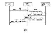
図3は、本開示の実施例に係る、リモートデバイスにSPS配置を実行するシグナリングフローチャートである。図3に示したネットワーク側デバイスは、本開示に係る電子機器200を採用してもよい。図3に示すように、ステップS301において、リモートデバイスは、望ましい構築するSPS配置の周期及び数などを指示するためのUEAssistanceInformationメッセージを中継デバイスに送信する。次に、ステップS302において、中継デバイスは、当該UEAssistanceInformationメッセージをネットワーク側デバイスに転送する。次に、ステップS303において、ネットワーク側デバイスは、中継デバイスにリモートデバイスのSPS配置情報を送信する。このステップにおいて、ネットワーク側デバイスは、リモートデバイスのSPS配置情報の宛先端末が中継デバイスであるように指示するための指示情報を生成してもよい。次に、ステップS304において、中継デバイスは、当該リモートデバイスのSPS配置情報を保存する。次に、ステップS305において、ネットワーク側デバイスは、再び、中継デバイスにリモートデバイスのSPS配置情報を送信する。このようなステップにおいて、送信のSPS配置情報の内容は、ステップS303において送信されたSPS配置情報の内容と同じであってもよい。なお、ステップS305において、ネットワーク側デバイスは、リモートデバイスのSPS配置情報の宛先端末が中継デバイスではなくリモートデバイスであるように指示するための指示情報を生成してもよい。次に、ステップS306において、中継デバイスは、リモートデバイスに当該リモートデバイスのSPS配置情報を直接に転送する。 FIG. 3 is a signaling flowchart for performing SPS placement on a remote device, according to an embodiment of the present disclosure. The network-side device shown in FIG. 3 may employ the electronic device 200 according to the present disclosure. As shown in FIG. 3, in step S301, the remote device sends a UEAAssistanceInformation message to the relay device to indicate the desired period and number of SPS arrangements to be constructed. Then, in step S302, the relay device forwards the UEAAssistanceInformation message to the network side device. Next, in step S303, the network side device transmits the SPS arrangement information of the remote device to the relay device. In this step, the network-side device may generate indication information for indicating that the destination terminal of the SPS configuration information of the remote device is the relay device. Next, in step S304, the relay device saves the SPS arrangement information of the remote device. Next, in step S305, the network side device again sends the SPS location information of the remote device to the relay device. In such a step, the content of the SPS location information sent may be the same as the content of the SPS location information sent in step S303. In step S305, the network-side device may generate instruction information for instructing that the destination terminal of the SPS arrangement information of the remote device is not the relay device but the remote device. Then, in step S306, the relay device directly forwards the SPS configuration information of the remote device to the remote device.
上記したように、本開示は、本質的には、ネットワーク側デバイスから中継デバイスに送信するメッセージの宛先を指示する方法を提供する。つまり、上記の指示情報は、SPS配置情報の宛先端末を示すことだけではなく、通常のメッセージの宛先端末を示してもよい。例えば、電子機器200の処理回路210は、電子機器200から中継デバイスに送信するメッセージの宛先端末が中継デバイスであるかどうかを指示するための指示情報を生成するように配置されてもよい。送受信回路220は、中継デバイスに当該指示情報を送信するように配置されてもよい。ここで、電子機器200から中継デバイスに送信するメッセージが、上位レイヤシグナリング、例えば、RRCシグナリングによって送信される。なお、電子機器200は、1ビットの情報で、この指示情報を示してもよい。例えば、指示情報が「0」である場合、メッセージの宛先端末が中継デバイスではなく、リモートデバイスであることを示す。指示情報が「1」である場合、メッセージの宛先端末が中継デバイスであることを示す。より具体的な実現方式はSPS配置の指示情報に類似するので、ここでは重複して説明しない。
As noted above, the present disclosure essentially provides a method of indicating the destination of a message sent from a network-side device to a relay device. In other words, the above instruction information may indicate not only the destination terminal of the SPS allocation information but also the destination terminal of a normal message. For example, processing circuitry 210 of electronic device 200 may be arranged to generate indication information for indicating whether the destination terminal of a message sent from electronic device 200 to a relay device is a relay device.
上記したように、本開示に係る第1のSPS配置情報を送信する方式によれば、電子機器200は、リモートデバイスのSPS配置情報の宛先端末が中継デバイスであるかどうかを指示するための指示情報を生成してもよい。このような指示情報は、1ビットの情報を含んでもよい。ネットワーク側デバイスは、中継デバイスに、中継デバイスが当該リモートデバイスのSPS配置情報を保存するためのリモートデバイスのSPS配置情報と、リモートデバイスが当該リモートデバイスのSPS配置情報を保存するためのリモートデバイスのSPS配置情報とを送信することによって、リモートデバイスへのSPSリソースの配置情報を実現する。 As described above, according to the method of transmitting the first SPS arrangement information according to the present disclosure, electronic device 200 sends an instruction for instructing whether the destination terminal of the SPS arrangement information of the remote device is a relay device. information may be generated. Such indication information may include one bit of information. The network-side device provides the relay device with SPS allocation information of the remote device for the relay device to store the SPS allocation information of the remote device, and the remote device's SPS allocation information for the remote device to store the SPS allocation information of the remote device. The SPS resource allocation information to the remote device is realized by transmitting the SPS allocation information.
第2の配置方式 Second placement method
第2のSPS配置情報を送信する方式では、処理回路210は、中継デバイスにリモートデバイスのSPS配置情報を転送して保存するように指示するための指示情報を生成するように配置されてもよく、送受信回路220は、さらに、中継デバイスへ指示情報を送信するように配置されてもよい。
In the scheme of transmitting the second SPS configuration information, the processing circuitry 210 may be arranged to generate instruction information for instructing the relay device to transfer and store the SPS configuration information of the remote device. , the transmit/receive
同様に、処理回路210は、アプリケーションレイヤ(Adaptation Layer)にこのような指示情報を含んでもよい。具体的に、処理回路210は、さらに、2ビットの情報でこのような指示情報を示すように配置されてもよい。例えば、指示情報が「10」である場合、中継デバイスがリモートデバイスのSPS配置情報を転送して保存することを示す。 Similarly, processing circuitry 210 may include such instructional information in an application layer (Adaptation Layer). Specifically, processing circuitry 210 may be further arranged to indicate such indication information in two bits of information. For example, if the indication information is '10', it indicates that the relay device transfers and stores the SPS configuration information of the remote device.
本開示の実施例によれば、中継デバイスはこのような指示情報を受信した場合、中継デバイスは、当該リモートデバイスのSPS配置情報を保存し、当該リモートデバイスのSPS配置をアンパック(例えば、上位レイヤアンパック)し、リモートデバイスの識別情報を抽出する。それとともに、中継デバイスは、当該リモートデバイスのSPS配置情報をリモートデバイスに直接に転送してもよい。ここの保存過程及び転送過程は、第1の方式に類似する。 According to an embodiment of the present disclosure, when a relay device receives such indication information, the relay device stores the SPS configuration information of the remote device and unpacks the SPS configuration of the remote device (e.g., higher layer unpack) and extract the identity of the remote device. At the same time, the relay device may directly forward the SPS configuration information of the remote device to the remote device. The storage and transfer processes here are similar to the first scheme.
本開示の実施例によれば、処理回路210は、上記2ビットの指示情報で、中継デバイスのリモートデバイスのSPS配置情報以外の他のメッセージに対する処理方式を指示してもよい。例えば、指示情報が「00」である場合、中継デバイスは、メッセージ(例えば、ネットワーク側デバイスからリモートデバイスに送信したメッセージ。当該メッセージにおける具体的な内容が中継デバイスにより取得される必要がない)をリモートデバイスに直接に転送する、即ち、メッセージを保存しなくて、メッセージをアンパック(例えば、上位レイヤアンパック)しないように指示する。指示情報が「01」である場合、中継デバイスはメッセージ(例えば、ネットワーク側デバイスから中継デバイスに送信したメッセージ)をローカルに保存する、即ち、メッセージをアンパック(例えば、上位レイヤアンパック)し、当該メッセージを転送しないように指示する。指示情報が「10」である場合、中継デバイスはメッセージ(例えば、上記のリモートデバイスのSPS配置情報)をローカルに保存し、メッセージをリモートデバイスに転送するように指示する。指示情報が「11」である場合、予約するように指示する。 According to an embodiment of the present disclosure, the processing circuit 210 may use the 2-bit indication information to indicate a processing scheme for messages other than the SPS configuration information of the remote device of the relay device. For example, if the indication information is "00", the relay device sends a message (for example, a message sent from the network-side device to the remote device. Specific content in the message does not need to be acquired by the relay device). Directly forward to the remote device, ie, do not store the message and tell it not to unpack (eg, higher layer unpack) the message. If the indication information is '01', the relay device locally stores the message (e.g., the message sent from the network-side device to the relay device), i.e. unpacks the message (e.g., unpacks the upper layer), and returns the message instruct not to forward If the indication information is "10", the relay device instructs to locally store the message (eg, the above SPS location information of the remote device) and forward the message to the remote device. If the instruction information is "11", it instructs to make a reservation.
上記したように、第2の方式において、本開示は、本質的に、中継デバイスがネットワーク側からのメッセージに対する処理方式を指示するための方法を提供する。つまり、処理回路210は、中継デバイスが電子機器200からのメッセージに対する処理方式を指示するための指示情報を生成するように配置されてもよく、送受信回路220は、このような指示情報を中継デバイスに送信してもよい。さらに、中継デバイスは、このような指示情報に従って、電子機器200からのメッセージに対して処理を実行してもよい。この処理は、当該メッセージをリモートデバイスに転送することと、当該メッセージを保存することとのうち、少なくともの1つを含む。本開示の実施例によれば、電子機器200からのメッセージは、上位レイヤシグナリング、例えば、RRCシグナリングによって送信されるメッセージであってもよい。
As noted above, in the second scheme, the present disclosure essentially provides a method for a relay device to indicate a processing scheme for messages from the network side. That is, the processing circuit 210 may be arranged to generate instruction information for instructing the relay device how to process the message from the electronic device 200, and the transmission/
図4は、本開示の他の実施例に係る、リモートデバイスにSPS配置を実行するシグナリングフローチャートである。図4に示されたネットワーク側デバイスは、本開示に係る電子機器200を採用してもよい。図4に示すように、ステップS401において、リモートデバイスは、望ましい構築するSPS配置の周期及び数などを指示するためのUEAssistanceInformationメッセージを中継デバイスに送信する。次に、ステップS402において、中継デバイスは、当該UEAssistanceInformationメッセージをネットワーク側デバイスに転送する。次に、ステップS403において、ネットワーク側デバイスは、中継デバイスにリモートデバイスのSPS配置情報を送信する。このステップにおいて、ネットワーク側デバイスは、中継デバイスにリモートデバイスのSPS配置情報を保存して転送するように指示するための指示情報を生成してもよい。次に、ステップS404において、中継デバイスは、当該リモートデバイスのSPS配置情報を保存して、即ち、当該SPS配置情報をアンパック(例えば、上位レイヤアンパック)する。次に、ステップS405において、中継デバイスは、リモートデバイスに当該SPS配置情報を転送してもよい。 FIG. 4 is a signaling flowchart for performing SPS placement on a remote device, according to another embodiment of the present disclosure. The network-side device shown in FIG. 4 may employ the electronic device 200 according to the present disclosure. As shown in FIG. 4, in step S401, the remote device sends a UEAAssistanceInformation message to the relay device to indicate the desired period and number of SPS arrangements to be constructed. Then, in step S402, the relay device forwards the UEAAssistanceInformation message to the network side device. Next, in step S403, the network side device transmits the SPS arrangement information of the remote device to the relay device. In this step, the network-side device may generate instruction information for instructing the relay device to store and forward the SPS configuration information of the remote device. Then, in step S404, the relay device stores the SPS configuration information of the remote device, ie unpacks (eg, higher layer unpacks) the SPS configuration information. Then, in step S405, the relay device may forward the SPS placement information to the remote device.
上記したように、本開示に係る第2のSPS配置情報を送信する方式によれば、電子機器200は、中継デバイスにリモートデバイスのSPS配置を転送して保存するように指示するための指示情報を生成してもよい。このような指示情報は、2ビットの情報を含んでもよい。ネットワーク側デバイスは、中継デバイスにリモートデバイスのSPS配置情報を一回だけで送信することによって、リモートデバイスへのSPSリソースの配置を実現する。 As described above, according to the method of transmitting the second SPS arrangement information according to the present disclosure, the electronic device 200 transmits the instruction information for instructing the relay device to transfer and save the SPS arrangement of the remote device. may be generated. Such indication information may include two bits of information. The network-side device realizes the allocation of SPS resources to the remote device by sending the SPS allocation information of the remote device to the relay device only once.
以上、リモートデバイスに対してSPS配置を実行する実施例を詳細に記述した。リモートデバイスは、SPS配置情報を受信した後、一般的にすぐにこのようなSPS配置を使用しないが、当該SPS配置をアクティブ化するためのアクティブ化情報を受信した後SPS配置を使用する。 Exemplary embodiments for performing SPS placement for remote devices are described above in detail. Remote devices generally do not use such SPS placements immediately after receiving SPS placement information, but use SPS placements after receiving activation information to activate the SPS placement.
本開示の実施例によれば、処理回路210(例えば、アクティブ化情報生成ユニット,図示せず)は、さらに、リモートデバイスのSPS配置をアクティブ化するためのアクティブ化情報を生成するように配置されてもよく、送受信回路220は、さらに、中継デバイスヘアクティブ化情報を送信するように配置されてもよい。
According to embodiments of the present disclosure, the processing circuitry 210 (eg, an activation information generating unit, not shown) is further arranged to generate activation information for activating the SPS arrangement of the remote device. and the transmit/receive
本開示の実施例によれば、送受信回路220は、さらに、下位レイヤシグナリングによって中継デバイスヘアクティブ化情報を送信するように配置されてもよい。例えば、送受信回路220は、PDCCH(Physical Downlink Control Channel)で、中継デバイスヘアクティブ化情報を送信してもよい。更具体的に、送受信回路220は、DCI(Downlink Control Information)を利用して中継デバイスヘアクティブ化情報を送信してもよい。
According to embodiments of the present disclosure, the transmit/receive
本開示の実施例によれば、処理回路210は、さらに、リモートデバイスの識別情報を利用して、DCIをスクランブルして、アクティブ化情報を生成するように配置されてもよい。具体的に、DCIは、フォーマット5A(format 5A)を採用されてもよい。ここで、DCIフォーマット5Aがスクランブルされた後、各ドメインの機能も従来のDCIフォーマット5Aと同じである。 According to embodiments of the present disclosure, processing circuitry 210 may be further arranged to utilize the identification information of the remote device to scramble the DCI to generate activation information. Specifically, the DCI may adopt format 5A. Here, after the DCI format 5A is scrambled, the function of each domain is also the same as the conventional DCI format 5A.
本開示の実施例によれば、アクティブ化情報には、SPS配置に対するリソース指示情報と、当該SPS配置をアクティブ化するアクティブ化指示情報を含んでもよい。 According to embodiments of the present disclosure, activation information may include resource indication information for an SPS deployment and activation indication information for activating the SPS deployment.
本開示の実施例によれば、電子機器200は、中継デバイスにSPS配置を解放するための解放情報を送信してもよい。解放情報の送信方式について、アクティブ化指示情報の送信方式と同じであってもよい。よって、本開示に記載のアクティブ化指示情報に関する全ての実施例は、いずれも解放情報に適用される。つまり、アクティブ化指示情報を送信する方式に類似して、電子機器200は、下位レイヤシグナリングによって中継デバイスにリモートデバイスのSPS配置に対する解放情報を送信してもよい。なお、電子機器200は、例えば、RRCシグナリングの上位レイヤシグナリングによって中継デバイスにリモートデバイスのSPS配置に対する解放情報を送信してもよい。 According to embodiments of the present disclosure, electronic device 200 may transmit release information to release the SPS placement to the relay device. The transmission method of the release information may be the same as the transmission method of the activation instruction information. Thus, all examples of activation indication information described in this disclosure apply to release information. That is, similar to the method of transmitting the activation indication information, the electronic device 200 may transmit the release information for the SPS configuration of the remote device to the relay device through lower layer signaling. Note that the electronic device 200 may transmit the release information for the SPS arrangement of the remote device to the relay device by, for example, higher layer signaling of RRC signaling.
本開示に係る一つの非限定的な実施例では、「sl SPS configuration index」でSPSに配置するリソース指示情報を示してもよく、「Activation/release indication」で当該SPS配置をアクティブ化/解放するアクティブ化/解放指示情報を示してもよい。なお、本開示に係る非限定的な実施例では、上位レイヤシグナリングに、「DCI format 5Aがsl-R-SPS-RNTIによってスクランブルされた場合、sl SPS configuration index- 3 bits,Activation/release indication-1 bitという域が存在する」というシグナリングを追加してもよい。もちろん、上記の例は限定的なものではなく、他のパラメータでSPSに配置するリソース指示情報及び当該SPS配置をアクティブ化するアクティブ化指示情報を示してもよく、他のシグナリングで上記情報を示してもよい。 In one non-limiting embodiment according to the present disclosure, 'sl SPS configuration index' may indicate resource indication information to be configured in the SPS, and 'Activation/release indication' activates/releases the SPS configuration. Activation/release indication information may be indicated. In a non-limiting embodiment according to the present disclosure, the higher layer signaling includes "When DCI format 5A is scrambled by sl-R-SPS-RNTI, sl SPS configuration index- 3 bits, Activation/release indication- A 1-bit area exists" may be added. Of course, the above examples are not limiting, other parameters may indicate the resource indication information to be allocated to the SPS and the activation indication information to activate the SPS allocation, and other signaling may be used to indicate the above information. may
本開示の実施例によれば、中継デバイスは、アクティブ化情報を受信した後、リモートデバイスに当該アクティブ化情報を転送してもよい。この部分について、次に詳細に説明する。 According to embodiments of the present disclosure, after receiving the activation information, the relay device may forward the activation information to the remote device. This part will now be described in detail.
本開示の実施例によれば、処理回路210は、さらに、アクティブ化情報の宛先リモートデバイスを確認するための確認情報を生成するように配置されてもよく、送受信回路220は、さらに、中継デバイスへ確認情報を送信するように配置されてもよい。ここで、電子機器200は、中継デバイスからリモートデバイスへ当該確認情報を転送するように、中継デバイスへ確認情報を送信してもよい。本開示の実施例によれば、確認情報には、リモートデバイスのSPS配置をアクティブ化するアクティブ化指示情報を含む。つまり、リモートデバイスは電子機器200からの確認情報を受信した後、そのSPS配置をアクティブ化して、即ち、SPS配置におけるリソースを使用して始める。
According to embodiments of the present disclosure, the processing circuitry 210 may be further arranged to generate confirmation information for confirming the destination remote device of the activation information, and the
本開示の実施例によれば、処理回路210は、MAC(Media Access Control) CE (Control Element)を利用して確認情報を生成してもよい。さらに、処理回路210は、MAC PDU(Protocol Data Unit)サブヘッダのLCID(logical channel identify)における予約ビット(予約ビット「10111」を含むが、これらに限定されない)を利用して確認情報を生成してもよい。 According to embodiments of the present disclosure, processing circuitry 210 may utilize a Media Access Control (MAC) Control Element (CE) to generate confirmation information. Furthermore, the processing circuit 210 generates confirmation information using reserved bits (including, but not limited to, reserved bits “10111”) in the LCID (logical channel identify) of the MAC PDU (Protocol Data Unit) subheader. good too.
上記したように、電子機器200は、リモートデバイスのSPS配置をアクティブ化するように、中継デバイスを介してリモートデバイスにSPS配置をアクティブ化するためのアクティブ化情報を送信してもよく、中継デバイスを介してリモートデバイスへ確認情報を送信してもよい。これにより、SPS技術端末装置間の通信に適用することにより、機器間の通信の信頼性が向上し、遅延が減少し、異なるビジネス及び流量タイプのQoS要求を満たすことができる。 As described above, the electronic device 200 may transmit activation information for activating the SPS placement to the remote device via the relay device to activate the SPS placement of the remote device, and the relay device may activate the SPS placement. The confirmation information may be sent to the remote device via the . Therefore, by applying it to communication between SPS technology terminal devices, the reliability of communication between devices can be improved, the delay can be reduced, and the QoS requirements of different business and flow types can be met.
<3.第2実施例> <3. Second embodiment>
この実施例において、本開示の実施例に係る電子機器500について詳細に説明する。ここの電子機器500は、無線通信システムにおける中継デバイス、例えば、図1(a)と図1(b)に示された中継デバイスであってもよい。図5は、本開示の実施例に係る電子機器500の配置の例のブロック図である。 In this example, the electronic device 500 according to the example of the present disclosure will be described in detail. The electronic device 500 here may be a relay device in a wireless communication system, such as the relay device shown in FIGS. 1(a) and 1(b). FIG. 5 is a block diagram of an example arrangement of an electronic device 500 according to an embodiment of the disclosure.
図5に示すように、電子機器500は、処理回路510と送受信回路520を含んでもよい。なお、電子機器500は、一つの処理回路510を含んでもよく、複数の処理回路510を含んでもよい。
As shown in FIG. 5, electronic device 500 may include processing circuitry 510 and
さらに、処理回路510は、様々な異なる機能及び/又は操作を実行するように、様々な別個の機能ユニットを含んでもよい。なお、これらの機能ユニットは、物理的エンティティ又は論理的エンティティであってもよく、そして異なる名称のユニットは同一物理的エンティティによって実現されてもよい。 Further, processing circuitry 510 may include various separate functional units to perform various different functions and/or operations. Note that these functional units may be physical entities or logical entities, and differently named units may be realized by the same physical entity.
本開示の実施例によれば、処理回路510は、処理ユニット511を含んでもよい。
According to embodiments of the present disclosure, processing circuitry 510 may include a
本開示の実施例によれば、送受信回路520は、電子機器500にサービスを提供するネットワーク側デバイスから、電子機器500を介してネットワーク側デバイスと通信するリモートデバイスのSPS配置情報を受信してもよい。ここで、ネットワーク側デバイスは、例えば、第1実施例に記載の電子機器200であってもよい。
According to embodiments of the present disclosure, the
本開示の実施例によれば、処理回路510における処理ユニット511は、SPS配置情報を保存することと、送受信回路520を制御してリモートデバイスヘSPS配置情報を送信することとのうち少なくとも一つを実行してもよい。
According to embodiments of the present disclosure, the
上記したように、本開示の実施例に係る電子機器500は、ネットワーク側デバイスから、リモートデバイスのSPS配置情報を受信してもよく、当該SPS配置を保存する又はリモートデバイスに当該SPS配置情報を転送してもよい。これにより、異なるビジネス及び流量タイプのQoS要求を満たすことができる。 As described above, the electronic device 500 according to the embodiments of the present disclosure may receive the SPS placement information of the remote device from the network side device, and store the SPS placement information or send the SPS placement information to the remote device. may be transferred. This allows meeting the QoS requirements of different business and flow types.
本開示の実施例によれば、送受信回路520は、上位レイヤシグナリングによってリモートデバイスのSPS配置情報、例えば、以上に説明したRRCシグナリングを受信するように配置されてもよい。
According to embodiments of the present disclosure, the
本開示の実施例によれば、SPS配置情報は、SPS配置情報に対応するリモートデバイスの識別情報、例えば、以上に説明したRNTIを含んでもよい。 According to embodiments of the present disclosure, the SPS location information may include identification information of the remote device corresponding to the SPS location information, eg, the RNTI described above.
以上では説明したように、第1のSPS配置を送信する方式では、本開示の実施例によれば、送受信回路520は、ネットワーク側デバイスから、SPS配置情報の宛先端末が電子機器500であるかどうかを指示するための指示情報を受信してもよい。さらに、処理回路520では、指示情報はSPS配置情報の宛先端末が電子機器500である場合、SPS配置情報を保存し、指示情報はSPS配置情報の宛先端末が電子機器500ではない場合、送受信回路520を制御してリモートデバイスヘSPS配置情報を送信してもよい。
As described above, in the method of transmitting the first SPS arrangement, according to the embodiment of the present disclosure, the transmission/
本開示の実施例によれば、電子機器500は、アプリケーションレイヤにおけるローカルアイデンティティ(local ID)によって、SPS配置情報の宛先がどのリモートデバイスであるかを識別することで、SPS配置情報を対応するリモートデバイスを転送してもよい。 According to an embodiment of the present disclosure, the electronic device 500 identifies which remote device is the destination of the SPS location information by a local ID in the application layer, and sends the SPS location information to the corresponding remote device. You can transfer your device.
以上では説明したように、第2のSPS配置情報を送信する方式では、送受信回路520は、ネットワーク側デバイスから、電子機器500にリモートデバイスのSPS配置情報を保存して転送するように指示するための指示情報を受信してもよい。このような指示情報を受信する場合、処理回路510は、SPS配置情報を保存し、送受信回路520を制御してリモートデバイスヘSPS配置情報を送信してもよい。
As described above, in the method of transmitting the second SPS arrangement information, the transmission/
本開示の実施例によれば、処理回路510は、SPS配置情報を保存する場合、当該SPS配置情報を(例えば、上位レイヤアンパック)アンパックすることで、リモートデバイスの識別情報を抽出してもよい。 According to embodiments of the present disclosure, if processing circuitry 510 stores SPS configuration information, processing circuitry 510 may unpack (e.g., higher layer unpack) the SPS configuration information to extract the identity of the remote device. .
本開示の実施例に係る、二つのSPS配置情報を送信する方式は第1実施例の説明で詳細に説明したので、ここでは重複して説明しない。次に、本開示の実施例に係る、いくつのSPS配置をアクティブ化する方式について詳細に説明する。 Since the method of transmitting two pieces of SPS configuration information according to the embodiment of the present disclosure has been described in detail in the description of the first embodiment, it will not be described again here. A scheme for activating how many SPS constellations according to embodiments of the present disclosure will now be described in detail.
本開示の実施例によれば、送受信回路520は、ネットワーク側デバイスから、リモートデバイスのSPS配置をアクティブ化するための第1アクティブ化情報を受信するように配置されていてもよい。以上では説明したように、送受信回路520は、さらに、下位レイヤシグナリングによってネットワーク側デバイスから、第1アクティブ化情報を受信するように配置されていてもよい。例えば、送受信回路520は、PDCCH(Physical Downlink Control Channel)で、ネットワーク側デバイスから第1アクティブ化情報を受信してもよい。更具体的に、送受信回路520は、DCI(Downlink Control Information)で、ネットワーク側デバイスから第1アクティブ化情報を受信してもよい。
According to embodiments of the present disclosure, the
本開示の実施例によれば、第1アクティブ化情報は、SPS配置に対するリソース指示情報及び当該SPS配置をアクティブ化するアクティブ化指示情報を含んでもよい。なお、第1アクティブ化情報は、ネットワーク側デバイスリモートデバイスの識別情報を利用してDCIをスクランブルすることによって、生成される。 According to embodiments of the present disclosure, the first activation information may include resource indication information for an SPS deployment and activation indication information for activating the SPS deployment. It should be noted that the first activation information is generated by scrambling the DCI using the identification information of the network side device remote device.
本開示の実施例によれば、処理回路510は、リモートデバイスの識別情報を利用して、第1アクティブ化情報をデスクランブルしてもよい。以上のように、電子機器500は、それと接続関係があるリモートデバイスのSPS配置を保存することで、リモートデバイスの識別情報を取得してもよい。電子機器500が複数のリモートデバイスに接続されている場合、電子機器500は、複数のリモートデバイスの識別情報を取得できる。なお、電子機器500は、電子機器500の自身の識別情報を取得してもよい。つまり、電子機器500は、ネットワーク側デバイスから、電子機器500とリモートデバイスとの間の通信に用いられるSPS配置情報、及び、電子機器500とネットワーク側デバイスとの間の通信に用いられるSPS配置情報を受信してもよい。この2つのSPS配置情報は、それぞれ、電子機器500の第1識別情報(リモートデバイスとの間の通信に対するSPS配置情報)と第2識別情報(ネットワーク側デバイスとの間の通信に対する)を含んでもよい。電子機器500は、第1アクティブ化情報を受信した後、全てのリモートデバイスの識別情報及び電子機器500の自身の識別情報を利用して、当該第1アクティブ化情報をデスクランブルしようとすることで、第1アクティブ化情報を正しくデスクランブルできる識別情報を見つける。このようにすると、電子機器500は、第1アクティブ化情報がどのリモートデバイスに対応するかを示すアクティブ化情報を識別することができる。 According to embodiments of the present disclosure, processing circuitry 510 may utilize the identification information of the remote device to descramble the first activation information. As described above, the electronic device 500 may acquire the identification information of the remote device by storing the SPS arrangement of the remote device connected thereto. When the electronic device 500 is connected to multiple remote devices, the electronic device 500 can acquire identification information of the multiple remote devices. Electronic device 500 may acquire its own identification information. That is, the electronic device 500 receives SPS arrangement information used for communication between the electronic device 500 and the remote device and SPS arrangement information used for communication between the electronic device 500 and the network side device from the network side device. may be received. The two pieces of SPS arrangement information may include first identification information (SPS arrangement information for communication with remote devices) and second identification information (for communication with network-side devices) of electronic device 500, respectively. good. After receiving the first activation information, the electronic device 500 attempts to descramble the first activation information using the identification information of all remote devices and the identification information of the electronic device 500 itself. , find identification information that can correctly descramble the first activation information. In this manner, electronic device 500 can identify activation information indicating which remote device the first activation information corresponds to.
本開示の実施例によれば、処理回路510は、リモートデバイスのSPS配置をアクティブ化するための第2アクティブ化情報を生成してもよく、送受信回路520は、リモートデバイスに第2アクティブ化情報を送信してもよい。
According to embodiments of the present disclosure, processing circuitry 510 may generate second activation information for activating the SPS arrangement of the remote device, and
ここで、送受信回路520は、上位レイヤシグナリングによってリモートデバイスに第2アクティブ化情報を送信してもよい。例えば、送受信回路520は、RRCシグナリングによって、リモートデバイスに第2アクティブ化情報を送信してもよい。具体的に、電子機器500は第1アクティブ化情報がどのリモートデバイスに対応するかを識別した後、RRCシグナリングを利用して、リモートデバイスに第2アクティブ化情報を直接に送信することとしてもよい。ここの第2アクティブ化情報は、リモートデバイスのSPS配置に対するリソース指示情報、及び、当該SPS配置をアクティブ化するアクティブ化指示情報を含んでもよい。なお、送受信回路520は、下位レイヤシグナリングによって、リモートデバイスに第2アクティブ化情報を送信してもよい。本開示の実施例によれば、送受信回路520は、PSCCH(Physical Sidelink Control Channel)によって、リモートデバイスに第2アクティブ化情報を送信してもよい。以下の三つのアクティブ化方式は、いずれも下位レイヤシグナリングで第2アクティブ化情報を送信する。
Here, the
第1のアクティブ化方式 First activation method
第1のアクティブ化方式では、送受信回路520は、下位レイヤシグナリング、例えば、PSCCHによって、リモートデバイスに第2アクティブ化情報を送信してもよい。
In a first activation scheme, the transmit/receive
なお、処理回路520は、リモートデバイスの識別情報を利用して、SCI(Sidelink Control Information)をスクランブルして、第2アクティブ化情報を生成してもよい。具体的に、SCIフォーマット2(format 2)を採用してもよい。ここで、SCIフォーマット2とは、本開示において、電子機器500はリモートデバイスに送信するアクティブ化情報を生成するための、新しく定義されるSCIフォーマットである。本開示の実施例によれば、SCIフォーマット2の各ドメインの機能は、従来のDCIフォーマット5Aが電子機器500の第1識別情報によってスクランブルされたものと同じである。この方式では、リモートデバイスは第2アクティブ化情報を受信した時、自身の識別情報で第2アクティブ化情報を正しくデスクランブルすれば、SPS配置をアクティブ化してもよい。
Note that the
図6は、本開示に係る第1のアクティブ化方式のシグナリングフローチャートである。図6に示される中継デバイスは、本開示の実施例に係る電子機器500であってもよく、ネットワーク側デバイスは本開示の実施例に係る電子機器200であってもよい。 FIG. 6 is a signaling flowchart of a first activation scheme according to the present disclosure. The relay device shown in FIG. 6 may be the electronic device 500 according to the embodiment of the present disclosure, and the network side device may be the electronic device 200 according to the embodiment of the present disclosure.
図6に示すように、ステップS601において、ネットワーク側デバイスは、中継デバイスへ第1アクティブ化情報を送信する。ここの第1アクティブ化情報は、リモートデバイスの識別情報によってスクランブルされたものであってもよい。次に、ステップS602において、中継デバイスは、取得した全てのリモートデバイスの識別情報及び中継デバイスの識別情報を利用して、第1アクティブ化情報をデスクランブルすることで、第1アクティブ化情報に対応するリモートデバイスを確定する。次に、ステップS603において、中継デバイスリモートデバイスの識別情報を利用して、SCIフォーマット2をスクランブルして第2アクティブ化情報を生成する。次に、ステップS604において、中継デバイスは、リモートデバイスに第2アクティブ化情報を送信する。 As shown in FIG. 6, in step S601, the network-side device sends first activation information to the relay device. The first activation information here may be scrambled with the identification information of the remote device. Next, in step S602, the relay device uses the obtained identification information of all the remote devices and the identification information of the relay device to descramble the first activation information to correspond to the first activation information. Confirm the remote device to be used. Next, in step S603, the identification information of the relay device-remote device is used to scramble the SCI format 2 to generate the second activation information. Then, in step S604, the relay device sends the second activation information to the remote device.
上記したように、在第1のアクティブ化方式では、中継デバイスは、リモートデバイスにスクランブルされたアクティブ化情報を送信してもよい。この実施例において、第2アクティブ化情報は、リモートデバイスのSPS配置に対するリソース指示情報、及び、当該SPS配置をアクティブ化するアクティブ化指示情報を含んでもよい。リモートデバイスは、自身の識別情報で第2アクティブ化情報を正しくデスクランブルする場合、リソース指示情報に指示しているSPS配置をアクティブ化してもよい。 As noted above, in the first activation scheme, the relay device may send scrambled activation information to the remote device. In this embodiment, the second activation information may include resource indication information for the SPS arrangement of the remote device and activation indication information for activating the SPS arrangement. If the remote device correctly descrambles the second activation information with its own identification information, it may activate the SPS placement indicated in the resource indication information.
本開示に係る一つの非限定的な実施例において、「sl SPS configuration index」でSPSに配置するリソース指示情報を示してもよく、「Activation/release indication」で当該SPS配置をアクティブ化/解放するアクティブ化/解放指示情報を示してもよい。なお、本開示に係る非限定的な実施例において、上位レイヤシグナリングに「SCI format 2がsl-R-SPS-RNTIスクランブルされた場合、sl SPS configuration index- 3 bits,Activation/release indication-1 bitというドメインが存在する」というシグナリングを追加してもよい。もちろん、上記の例は、限定的なものではなく、他のパラメータでSPSに配置するリソース指示情報及び当該SPS配置をアクティブ化するアクティブ化指示情報を示してもよく、他のシグナリングで上記情報を示してもよい。 In one non-limiting embodiment according to the present disclosure, 'sl SPS configuration index' may indicate resource indication information to be configured in the SPS, and 'Activation/release indication' activates/releases the SPS configuration. Activation/release indication information may be indicated. In a non-limiting embodiment according to the present disclosure, in the higher layer signaling, "If SCI format 2 is sl-R-SPS-RNTI scrambled, sl SPS configuration index-3 bits, Activation/release indication-1 bit A domain called "exists" may be added. Of course, the above example is non-limiting, and other parameters may indicate the resource indication information to be placed in the SPS and the activation indication information to activate the SPS placement, and other signaling may be used to convey the above information. can be shown.
第2のアクティブ化方式 Second activation method
在第2のアクティブ化方式では、送受信回路520は、下位レイヤシグナリング、例えば、PSCCHによって、リモートデバイスに第2アクティブ化情報を送信してもよい。
In a second activation scheme, the transmit/receive
ここで、電子機器500は、第2アクティブ化情報をスクランブルしなくて、リモートデバイスへスクランブルされない第2アクティブ化情報を直接に送信する。この実施例において、第2アクティブ化情報は、リモートデバイスのSPS配置に対するリソース指示情報を含むが、リモートデバイスのSPS配置をアクティブ化するアクティブ化指示情報を含まない。第2アクティブ化情報はスクランブルされないので、リモートデバイスは、第2アクティブ化情報が自身に対応するアクティブ化情報であるかどうかを知ることができない。これにより、この実施例において、リモートデバイスは、第2アクティブ化情報の宛先リモートデバイスを確認するための確認情報を受信する必要がある。 Here, the electronic device 500 does not scramble the second activation information and directly transmits the unscrambled second activation information to the remote device. In this embodiment, the second activation information includes resource indication information for the SPS placement of the remote device, but does not include activation indication information for activating the SPS placement of the remote device. Since the secondary activation information is not scrambled, the remote device cannot know whether the secondary activation information is its corresponding activation information. Thus, in this embodiment, the remote device needs to receive confirmation information to confirm the destination remote device of the second activation information.
本開示の実施例によれば、送受信回路520は、ネットワーク側デバイスから、第2アクティブ化情報の宛先リモートデバイスを確認するための確認情報を受信してもよい。ここの確認情報は、リモートデバイスのSPS配置をアクティブ化するアクティブ化指示情報を含む。さらに、送受信回路520は、リモートデバイスへ当該確認情報を転送してもよい。このようにすると、リモートデバイスは、宛先が自身である確認情報を受信しただけで、第2アクティブ化情報に指示しているSPS配置をアクティブ化する。
According to embodiments of the present disclosure, the
図7は、本開示に係る第2のアクティブ化方式のシグナリングフローチャートである。図7に示される中継デバイスは、本開示の実施例に係る電子機器500であってもよく、ネットワーク側デバイスは、本開示の実施例に係る電子機器200であってもよい。 FIG. 7 is a signaling flowchart of a second activation scheme according to the present disclosure; The relay device shown in FIG. 7 may be the electronic device 500 according to the embodiment of the present disclosure, and the network-side device may be the electronic device 200 according to the embodiment of the present disclosure.
図7に示すように、ステップS701において、ネットワーク側デバイスは、中継デバイスへ第1アクティブ化情報を送信する。ここの第1アクティブ化情報は、リモートデバイスの識別情報によってスクランブルされたものであってもよい。次に、ステップS702において、中継デバイスは、取得した全てのリモートデバイスの識別情報を利用して、第1アクティブ化情報をデスクランブルして、第1アクティブ化情報に対応するリモートデバイスを確定する。次に、ステップS703において、中継デバイスは、リモートデバイスへスクランブルされない第2アクティブ化情報を送信する。次に、ステップS704において、ネットワーク側デバイスは、中継デバイスへ確認情報を送信する。次に、ステップS705において、中継デバイスは、リモートデバイスに確認情報を転送する。 As shown in FIG. 7, in step S701, the network side device sends first activation information to the relay device. The first activation information here may be scrambled with the identification information of the remote device. Next, in step S702, the relay device descrambles the first activation information using the obtained identification information of all remote devices to determine the remote device corresponding to the first activation information. Then, in step S703, the relay device sends unscrambled second activation information to the remote device. Next, in step S704, the network side device sends confirmation information to the relay device. Next, in step S705, the relay device forwards the confirmation information to the remote device.
第3のアクティブ化方式 Third activation method
第3のアクティブ化方式では、送受信回路520は、下位レイヤシグナリング、例えば、PSCCHによって、リモートデバイスに第2アクティブ化情報を送信してもよい。
In a third activation scheme, the transmit/receive
なお、電子機器500は、第2アクティブ化情報をスクランブルしなくて、リモートデバイスへスクランブルされない第2アクティブ化情報を直接に送信する。同様に、第2アクティブ化情報は、リモートデバイスのSPS配置に対するリソース指示情報を含んでもよい。本開示の実施例によれば、処理回路510(例えば、確認情報生成ユニット、図示せず)は、第2アクティブ化情報の宛先リモートデバイスを確認するための確認情報を生成してもよく、送受信回路520は、リモートデバイスへ確認情報を送信してもよい。このようにすると、リモートデバイスは、宛先が自身である確認情報を受信しただけで、第2アクティブ化情報に指示しているSPS配置をアクティブ化する。
Note that the electronic device 500 does not scramble the second activation information and directly transmits the unscrambled second activation information to the remote device. Similarly, the second activation information may include resource indication information for SPS placement of the remote device. According to embodiments of the present disclosure, processing circuitry 510 (e.g., a verification information generation unit, not shown) may generate verification information for verifying the destination remote device of the second activation information, and may transmit and receive
つまり、第3のアクティブ化方式と第2のアクティブ化方式との違いところは、ネットワーク側デバイスではなく、中継デバイスが確認情報を生成することにある。本開示の実施例によれば、処理回路510は、MAC CEを利用して確認情報を生成してもよい。さらに、処理回路510は、MAC PDUのサブヘッダのLCIDにおける予約ビットを利用して確認情報を生成してもよい。 That is, the difference between the third activation method and the second activation method is that the relay device generates the confirmation information instead of the network side device. According to embodiments of the present disclosure, processing circuitry 510 may utilize MAC CE to generate confirmation information. Additionally, processing circuitry 510 may utilize reserved bits in the LCID of the subheader of the MAC PDU to generate confirmation information.
図8は、本開示に係る第3のアクティブ化方式のシグナリングフローチャートである。図8に示される中継デバイスは、本開示の実施例に係る電子機器500であってもよく、ネットワーク側デバイスは、本開示の実施例に係る電子機器200であってもよい。 FIG. 8 is a signaling flowchart of a third activation scheme according to the present disclosure. The relay device shown in FIG. 8 may be the electronic device 500 according to the embodiment of the present disclosure, and the network-side device may be the electronic device 200 according to the embodiment of the present disclosure.
図8に示すように、ステップS801において、ネットワーク側デバイスは、中継デバイスへ第1アクティブ化情報を送信する。ここの第1アクティブ化情報は、リモートデバイスの識別情報によってスクランブルされたものであってもよい。次に、ステップS802において、中継デバイスは、取得した全てのリモートデバイスの識別情報を利用して、第1アクティブ化情報をデスクランブルして、第1アクティブ化情報に対応するリモートデバイスを確定する。次に、ステップS803において、中継デバイスは、リモートデバイスへスクランブルされない第2アクティブ化情報を送信する。次に、ステップS804において、中継デバイスは、確認メッセージを生成しリモートデバイスへ確認情報を送信する。 As shown in FIG. 8, in step S801, the network side device sends first activation information to the relay device. The first activation information here may be scrambled with the identification information of the remote device. Next, in step S802, the relay device descrambles the first activation information using the obtained identification information of all remote devices to determine the remote device corresponding to the first activation information. Then, in step S803, the relay device sends unscrambled second activation information to the remote device. Next, in step S804, the relay device generates a confirmation message and sends the confirmation information to the remote device.
上記したように、第2及び第3のアクティブ化方式では、中継デバイスは、リモートデバイスへスクランブルされない第2アクティブ化情報を送信してもよい。第2アクティブ化情報は、リモートデバイスのSPS配置に対するリソース指示情報を含んでもよい。なお、ネットワーク側デバイス又は中継デバイスは、第2アクティブ化情報の宛先リモートデバイスを確認する確認メッセージを生成してもよい。確認メッセージは、リモートデバイスのSPS配置をアクティブ化するアクティブ化指示情報を含んでもよい。つまり、リモートデバイスは、宛先が自身である確認メッセージを受信しただけで、第2アクティブ化メッセージに指示しているSPS配置をアクティブ化する。 As noted above, in the second and third activation schemes, the relay device may send unscrambled second activation information to the remote device. The second activation information may include resource indication information for SPS placement of the remote device. In addition, the network-side device or the relay device may generate a confirmation message for confirming the destination remote device of the second activation information. The confirmation message may include activation indication information to activate the SPS placement of the remote device. That is, the remote device activates the SPS arrangement indicated in the second activation message only upon receiving a confirmation message addressed to itself.
第2及び第3のアクティブ化方式では、第2アクティブ化情報にはリモートデバイスのSPS配置に対するリソース指示情報のみを含むので、本開示に係る一つの非限定的な実施例において、追加されたシグナリングには、「sl SPS configuration index- 3 bits」のみ含み、「Activation/release indication-1 bit」を含まない。もちろん、上記の例は、限定的なものではなく、他のシグナリングで上記情報を示してもよい。 In the second and third activation schemes, the second activation information only includes resource indication information for the SPS placement of the remote device, so in one non-limiting embodiment according to the present disclosure, additional signaling contains only "sl SPS configuration index-3 bits" and does not contain "Activation/release indication-1 bit". Of course, the above example is not limiting and other signaling may indicate the above information.
上記したように、本開示の実施例に係る電子機器500は、リモートデバイスへSPS配置情報及びSPSアクティブ化情報を転送して、SPS技術を端末装置間の通信に適用してもよい。これにより、機器間の通信の信頼性が向上し、遅延が減少し、異なるビジネス及び流量タイプのQoS要求を満たすことができる。 As described above, the electronic device 500 according to embodiments of the present disclosure may transfer SPS placement information and SPS activation information to remote devices to apply SPS techniques to communications between end devices. This improves the reliability of communication between devices, reduces delays, and can meet the QoS requirements of different business and flow types.
本開示の実施例によれば、電子機器500は、ネットワーク側デバイスである電子機器200のサービス範囲内に位置してもよい。これにより、第1実施例における電子機器200に関する全ての実施方式は、これに適用可能である。 According to embodiments of the present disclosure, the electronic device 500 may be located within the service range of the network-side device, the electronic device 200 . Accordingly, all implementation methods regarding the electronic device 200 in the first embodiment are applicable to this.
<4.第3実施例> <4. Third embodiment>
この実施例において、本開示の実施例に係る電子機器900について詳細に説明する。ここの電子機器900は、無線通信システムにおけるリモートデバイスであってもよく、例えば、図1(a)及び図1(b)に示すようなリモートデバイスである。図9は、本開示の実施例に係る電子機器900の配置の例のブロック図である。 In this example, the electronic device 900 according to the example of the present disclosure will be described in detail. The electronic device 900 here may be a remote device in a wireless communication system, for example a remote device as shown in FIGS. 1(a) and 1(b). FIG. 9 is a block diagram of an example arrangement of an electronic device 900 according to an embodiment of the disclosure.
図9に示すように、電子機器900は、処理回路910と送受信回路920を含んでもよい。なお、電子機器900は、一つの処理回路910を含んでもよく、複数の処理回路910を含んでもよい。
As shown in FIG. 9, electronic device 900 may include processing circuitry 910 and transmit/receive
さらに、処理回路910は、様々な異なる機能及び/又は操作を実行するように、様々な別個の機能ユニットを含んでもよい。なお、これらの機能ユニットは、物理的エンティティ又は論理的エンティティであってもよく、そして異なる名称のユニットは同一物理的エンティティによって実現されてもよい。 Further, processing circuitry 910 may include various separate functional units to perform various different functions and/or operations. Note that these functional units may be physical entities or logical entities, and differently named units may be realized by the same physical entity.
本開示の実施例によれば、処理回路910は、処理ユニット911を含んでもよい。
According to embodiments of the present disclosure, processing circuitry 910 may include a
本開示の実施例によれば、送受信回路920は、中継デバイスから、継装置を介して中継デバイスにサービスを提供するネットワーク側デバイスと通信する電子機器900のSPS配置情報を受信してもよい。ここで、中継デバイスは、例えば、第2実施例における電子機器500であってもよく、ネットワーク側デバイスは、例えば、第1実施例における電子機器200であってもよい。
According to embodiments of the present disclosure, the
本開示の実施例によれば、処理回路920における処理ユニット911は、SPS配置情報を保存してもよい。
According to embodiments of the present disclosure, processing
本開示の実施例によれば、送受信回路920は、上位レイヤシグナリングによってSPS配置情報を受信してもよい。上位レイヤシグナリングは、RRCシグナリングを含んでもよい。
According to embodiments of the present disclosure,
本開示の実施例によれば、SPS配置情報は、電子機器900の識別情報、例えば、RNTIを含んでもよい。ここで、処理ユニット911がSPS配置情報を保存することは、SPS配置情報における識別情報を抽出することを含んでもよい。
According to embodiments of the present disclosure, the SPS location information may include identification information of electronic device 900, eg, RNTI. Here, storing the SPS configuration information by the
本開示の実施例によれば、送受信回路920は、中継デバイスから、電子機器900のSPS配置をアクティブ化するためのアクティブ化情報を受信してもよい。
According to embodiments of the present disclosure,
本開示の実施例によれば、送受信回路920は、上位レイヤシグナリングによって、例えば、RRCシグナリング中継デバイスから、電子機器900のSPS配置をアクティブ化するためのアクティブ化情報を受信してもよい。ここで、処理回路910(例えば、アクティブ化ユニット、図示せず)は、中継デバイスからの上位レイヤシグナリングによって送信されたアクティブ化情報を受信した後、SPS配置をアクティブ化することしてもよい。
According to embodiments of the present disclosure,
なお、送受信回路920は、下位レイヤシグナリングによって、例えば、PSCCHで中継デバイスから、電子機器900のSPS配置をアクティブ化するためのアクティブ化情報を受信してもよい。
Note that the transmit/receive
上記した第1のアクティブ化方式では、中継デバイスからのアクティブ化情報は、スクランブルされたアクティブ化情報である。よって、本開示の実施例によれば、処理回路910(例えば、アクティブ化ユニット、図示せず)は、電子機器900の識別情報を利用して、アクティブ化情報を正しくデスクランブルする場合、SPS配置をアクティブ化することしてもよい。 In the first activation scheme described above, the activation information from the relay device is scrambled activation information. Thus, according to embodiments of the present disclosure, processing circuitry 910 (e.g., an activation unit, not shown) utilizes the identification information of electronic device 900 to properly descramble the activation information if SPS constellation may be activated.
上記した第2及び第3のアクティブ化方式では、中継デバイスからのアクティブ化情報は、スクランブルされない。よって、本開示の実施例によれば、送受信回路920は、中継デバイス又はネットワーク側デバイスからの確認情報を受信することしてもよく、処理回路910(例えば、アクティブ化ユニット、図示せず)は、確認情報はアクティブ化情報の宛先デバイスが電子機器900であるように示す場合、SPS配置をアクティブ化してもよい。
In the second and third activation schemes above, the activation information from the relay device is not scrambled. Thus, according to embodiments of the present disclosure, the
本開示の実施例によれば、中継デバイスは、一つ又は複数のリモートデバイスサービスであってもよい。つまり、一つ又は複数のリモートデバイスは同一中継デバイスを介してネットワーク側デバイスと通信してもよい。以上の説明では、いずれも一つのリモートデバイスを例として、本開示に係る実施例を説明した。しかしながら、複数のリモートデバイスが存在する場合、以上の説明も適用できる。 According to embodiments of the present disclosure, a relay device may be one or more remote device services. That is, one or more remote devices may communicate with the network side device via the same relay device. In the above description, the embodiments according to the present disclosure have been described using one remote device as an example. However, if there are multiple remote devices, the above description is also applicable.
図10は、本開示の実施例に係る、一つのリモートデバイスに対してSPS配置を実行し、当該SPS配置をアクティブ化するシグナリングフローチャートである。以上では説明したように、2つの方法でSPS配置情報を送信してもよく、3つの方式でSPS配置をアクティブ化してもよい。図10において、破線の枠で2つの配置方式及び3つのアクティブ化方式をそれぞれに示す。よって、実際の応用では、二つの配置方式から一つの方式を選択してSPS配置を実行してもよく、3つのアクティブ化方式から一つの方式を選択してSPS配置をアクティブ化してもよい。図10に示された詳細は先に説明されており、ここでは重複して説明しない。 FIG. 10 is a signaling flowchart for performing SPS deployment for one remote device and activating the SPS deployment, according to an embodiment of the present disclosure. As described above, SPS placement information may be transmitted in two ways, and SPS placement may be activated in three ways. In FIG. 10, the two placement schemes and the three activation schemes are respectively indicated by dashed boxes. Therefore, in practical application, one of the two deployment schemes may be selected to perform SPS deployment, and one of the three activation schemes may be selected to activate SPS deployment. The details shown in FIG. 10 have been previously described and will not be repeated here.
図11は、本開示の実施例に係る、複数のリモートデバイスに対してSPS配置を実行して、当該SPS配置をアクティブ化するシグナリングフローチャートである。図11において、図10に示された第1の配置方式及び第1のアクティブ化方式を選択して例として、複数のリモートデバイスの場合を説明する。特に、複数のリモートデバイスが存在する場合、同様に、第2の配置方式及び第2と第3のアクティブ化方式を選択してもよい。図11に示すように、リモートデバイス1及びリモートデバイス2は、それぞれ中継デバイスを介してネットワーク側デバイスにUEAssistanceInformation情報を送信する。ここで区別するために、リモートデバイス1からの情報UEAssistanceInformationをUEAssistanceInformation1として表記し、リモートデバイス2からの情報UEAssistanceInformationをUEAssistanceInformation2として表記する。次に、ネットワーク側デバイスは、それぞれ中継デバイスを介して、リモートデバイス1及びリモートデバイス2にSPS配置情報を送信する。そして、ネットワーク側デバイスは、それぞれ中継デバイスを介して、リモートデバイス1及びリモートデバイス2にSPS配置のアクティブ化情報をする。なお、本開示の実施例によれば、一つの中継デバイスが3つ以上のリモートデバイスにサービスを提供する場合、図11に類似する方式で処理を実行してもよい。
FIG. 11 is a signaling flowchart for performing SPS deployment for multiple remote devices and activating the SPS deployment, according to an embodiment of the present disclosure. In FIG. 11, the first deployment scheme and the first activation scheme shown in FIG. 10 are selected to illustrate the case of multiple remote devices as an example. Especially when there are multiple remote devices, the second deployment scheme and the second and third activation schemes may be selected as well. As shown in FIG. 11, the
上記したように、本開示の実施例に係る電子機器900は、ネットワーク側デバイスからのSPS配置情報を受信してもよく、ネットワーク側デバイス又は中継デバイスからのSPS配置をアクティブ化するためのアクティブ化情報及び確認情報を受信してもよい。従って、SPS配置がアクティブ化され、SPS技術を端末機器間の通信に適用することにより、機器間の通信の信頼性が向上し、遅延が減少し、異なるビジネス及び流量タイプのQoS要求を満たすことができる。 As described above, the electronic device 900 according to embodiments of the present disclosure may receive SPS placement information from a network-side device and may receive activation information for activating SPS placement from a network-side device or a relay device. Information and confirmation information may be received. Therefore, the SPS deployment is activated and the SPS technology is applied to the communication between the terminal devices to improve the reliability of the communication between the devices, reduce the delay, and meet the QoS requirements of different business and flow types. can be done.
本開示の実施例によれば、電子機器900は、中継デバイスである電子機器500を介してネットワーク側デバイスである電子機器200と通信してもよい。これにより、第1実施例における電子機器200に関する、第2実施例における電子機器500に関する全ての実施方式は、これに適用可能である。 According to embodiments of the present disclosure, the electronic device 900 may communicate with the network side device 200 via the relay device 500 . Accordingly, all the methods of implementing the electronic device 200 in the first embodiment and the electronic device 500 in the second embodiment are applicable to this.
<5.第4実施例> <5. Fourth embodiment>
次に、本開示に係るネットワーク側デバイスにより実行される無線通信方法について詳細に説明する。ここのネットワーク側デバイスは第1実施例における電子機器200であってもよいので、第1実施例における電子機器200の全ての実施方式は、これに適用可能である。 Next, the wireless communication method performed by the network-side device according to the present disclosure will be described in detail. The network-side device here may be the electronic device 200 in the first embodiment, so all implementation schemes of the electronic device 200 in the first embodiment are applicable to this.
図12は、本開示の実施例に係るネットワーク側デバイスにより実行される無線通信方法を示すフローチャートである。 FIG. 12 is a flowchart illustrating a wireless communication method performed by a network-side device according to an embodiment of the present disclosure;
図12に示すように、ステップS1210において、ネットワーク側デバイスのサービス範囲内の中継デバイスを介してネットワーク側デバイスと通信するリモートデバイスに対してSPS配置を実行する。 As shown in FIG. 12, in step S1210, SPS deployment is performed for remote devices that communicate with the network-side device through relay devices within service range of the network-side device.
次に、ステップS1220において、中継デバイスヘリモートデバイスのSPS配置情報を送信する。 Next, in step S1220, the SPS arrangement information of the remote device is transmitted to the relay device.
好ましくは、上位レイヤシグナリングによって中継デバイスヘリモートデバイスのSPS配置情報を送信する。 Preferably, the SPS location information of the remote device is transmitted to the relay device by higher layer signaling.
好ましくは、方法は、さらに、SPS配置情報に対応するリモートデバイスの識別情報を生成し、リモートデバイスの識別情報をリモートデバイスのSPS配置情報に含めることを含む。 Preferably, the method further includes generating identification information of the remote device corresponding to the SPS configuration information, and including the identification information of the remote device in the SPS configuration information of the remote device.
好ましくは、方法は、さらに、リモートデバイスのSPS配置情報の宛先端末が中継デバイスであるかどうかを指示するための指示情報を生成し、中継デバイスへ指示情報を送信することを含む。 Preferably, the method further includes generating indication information for indicating whether the destination terminal of the SPS configuration information of the remote device is the relay device, and transmitting the indication information to the relay device.
好ましくは、方法は、さらに、中継デバイスにリモートデバイスのSPS配置情報を転送して保存するように指示するための指示情報を生成することを含む。 Preferably, the method further includes generating instruction information for instructing the relay device to transfer and store the SPS configuration information of the remote device.
好ましくは、方法は、さらに、リモートデバイスのSPS配置をアクティブ化するためのアクティブ化情報を生成し、中継デバイスヘアクティブ化情報を送信することを含む。 Preferably, the method further includes generating activation information for activating the SPS arrangement of the remote device and transmitting the activation information to the relay device.
好ましくは、下位レイヤシグナリングによって中継デバイスヘアクティブ化情報を送信する。 Preferably, the activation information is sent to the relay device by lower layer signaling.
好ましくは、リモートデバイスの識別情報を利用して、アクティブ化情報を生成するように、下り制御情報DCIをスクランブルする。 Preferably, the identification information of the remote device is used to scramble the downlink control information DCI so as to generate the activation information.
好ましくは、方法は、さらに、アクティブ化情報の宛先リモートデバイスを確認するための確認情報を生成し、中継デバイスへ確認情報を送信することを含む。 Preferably, the method further comprises generating confirmation information for confirming the destination remote device of the activation information and transmitting the confirmation information to the relay device.
本開示の実施例に係るネットワーク側デバイスにより実行される無線通信方法は、第1実施例の説明で詳細に説明したので、ここで重複して説明しない。 Since the wireless communication method performed by the network-side device according to the embodiment of the present disclosure has been described in detail in the description of the first embodiment, it will not be described again here.
<6.第5実施例> <6. Fifth embodiment>
次に、本開示に係る中継デバイスにより実行される無線通信方法について詳細に説明する。ここの中継デバイスは第2実施例における電子機器500であってもよいので、第2実施例における電子機器500の全ての実施方式は、これに適用可能である。 Next, the wireless communication method performed by the relay device according to the present disclosure will be described in detail. Since the relay device here may be the electronic equipment 500 in the second embodiment, all implementation methods of the electronic equipment 500 in the second embodiment are applicable to this.
図13は、本開示の実施例に係る中継デバイスにより実行される無線通信方法を示すフローチャートである。 FIG. 13 is a flowchart illustrating a wireless communication method performed by a relay device according to an embodiment of the present disclosure;
図13に示すように、ステップS1310において、中継デバイスにサービスを提供するネットワーク側デバイスから、中継デバイスを介してネットワーク側デバイスと通信するリモートデバイスのSPS配置情報を受信する。 As shown in FIG. 13, in step S1310, SPS location information of remote devices communicating with the network-side device through the relay device is received from the network-side device that provides service to the relay device.
次に、ステップS1320において、SPS配置情報を保存することと、リモートデバイスヘSPS配置情報を送信することとのうち少なくとも一つを実行する。 Next, in step S1320, at least one of storing the SPS placement information and transmitting the SPS placement information to the remote device is performed.
好ましくは、上位レイヤシグナリングによってリモートデバイスのSPS配置情報を受信する。 Preferably, the remote device's SPS location information is received via higher layer signaling.
好ましくは、SPS配置情報は、SPS配置情報に対応するリモートデバイスの識別情報を含む。 Preferably, the SPS location information includes identification information of the remote device corresponding to the SPS location information.
好ましくは、方法は、さらに、ネットワーク側デバイスから、SPS配置情報の宛先端末が中継デバイスであるかどうかを指示するための指示情報を受信することを含む。 Preferably, the method further includes receiving, from the network-side device, indication information for indicating whether the destination terminal of the SPS location information is a relay device.
好ましくは、方法は、さらに、指示情報はSPS配置情報の宛先端末が中継デバイスであるように指示する場合、SPS配置情報を保存することを含む。 Preferably, the method further includes storing the SPS configuration information if the indication information indicates that the destination terminal of the SPS configuration information is a relay device.
好ましくは、方法は、さらに、指示情報はSPS配置情報の宛先端末が中継デバイスではないように指示する場合、リモートデバイスヘSPS配置情報を送信することとを含む。 Preferably, the method further includes transmitting the SPS configuration information to the remote device if the indication information indicates that the destination terminal of the SPS configuration information is not a relay device.
好ましくは、方法は、さらに、ネットワーク側デバイスから、中継デバイスにリモートデバイスのSPS配置情報を保存して転送するように指示するための指示情報を受信することを含む。 Preferably, the method further includes receiving instruction information from the network-side device for instructing the relay device to store and forward the SPS configuration information of the remote device.
好ましくは、方法は、さらに、SPS配置情報を保存し、リモートデバイスヘSPS配置情報を送信することとを含む。 Preferably, the method further includes storing the SPS placement information and transmitting the SPS placement information to the remote device.
好ましくは、方法は、さらに、ネットワーク側デバイスから、リモートデバイスのSPS配置をアクティブ化するための第1アクティブ化情報を受信することを含む。 Preferably, the method further includes receiving, from the network-side device, first activation information for activating the SPS deployment of the remote device.
好ましくは、下位レイヤシグナリングによって第1アクティブ化情報を受信する。 Preferably, the first activation information is received via lower layer signaling.
好ましくは、リモートデバイスの識別情報を利用して、第1アクティブ化情報をデスクランブルする。 Preferably, the identification information of the remote device is used to descramble the first activation information.
好ましくは、方法は、さらに、リモートデバイスのSPS配置をアクティブ化するための第2アクティブ化情報を生成することと、リモートデバイスに第2アクティブ化情報を送信することとを含む。 Preferably, the method further includes generating second activation information for activating the SPS arrangement of the remote device and transmitting the second activation information to the remote device.
好ましくは、下位レイヤシグナリングによってリモートデバイスに第2アクティブ化情報を送信する。 Preferably, the second activation information is sent to the remote device by lower layer signaling.
好ましくは、方法は、さらに、リモートデバイスの識別情報を利用して、第2アクティブ化情報を生成するように、サイドリンク制御情報SCIをスクランブルすることを含む。 Preferably, the method further comprises scrambling the sidelink control information SCI to generate the second activation information using the identification information of the remote device.
好ましくは、方法は、さらに、第2アクティブ化情報の宛先リモートデバイスを確認するための確認情報を生成することと、リモートデバイスへ確認情報を送信することとを含む。 Preferably, the method further includes generating confirmation information for confirming the destination remote device of the second activation information, and transmitting the confirmation information to the remote device.
本開示の実施例に係る中継デバイスにより実行される無線通信方法は、第2実施例の説明で詳細に説明したので、ここで重複して説明しない。 The wireless communication method performed by the relay device according to the embodiment of the present disclosure has been described in detail in the description of the second embodiment, so it will not be described again here.
<7.第6実施例> <7. Sixth embodiment>
次に、本開示に係るリモートデバイスにより実行される無線通信方法について詳細に説明する。ここのリモートデバイスは第3実施例における電子機器900であってもよいので、第3実施例における電子機器900の全ての実施方式は、これに適用可能である。 A wireless communication method performed by a remote device according to the present disclosure will now be described in detail. Since the remote device here may be the electronic device 900 in the third embodiment, all implementations of the electronic device 900 in the third embodiment are applicable to this.
図14は、本開示の実施例に係るリモートデバイスにより実行される方法を示すフローチャートである。 FIG. 14 is a flowchart illustrating a method performed by a remote device according to an embodiment of the disclosure.
図14に示すように、ステップS1410において、中継デバイスから、中継デバイスを介して中継デバイスにサービスを提供するネットワーク側デバイスと通信するリモートデバイスのSPS配置情報を受信する。 As shown in FIG. 14, in step S1410, SPS location information of remote devices communicating with network-side devices serving the relay device via the relay device is received from the relay device in step S1410.
次に、ステップS1420において、SPS配置情報を保存する。 Next, in step S1420, the SPS arrangement information is saved.
好ましくは、上位レイヤシグナリングによってSPS配置情報を受信する。 Preferably, the SPS location information is received via higher layer signaling.
好ましくは、SPS配置情報は、リモートデバイスの識別情報を含む。 Preferably, the SPS location information includes identification information of the remote device.
好ましくは、方法は、さらに、中継デバイスから、リモートサブデバイスのSPS配置をアクティブ化するためのアクティブ化情報を受信することを含む。 Preferably, the method further includes receiving activation information for activating the SPS arrangement of the remote sub-device from the relay device.
好ましくは、方法は、さらに、リモートデバイスの識別情報を利用して、アクティブ化情報を正しくデスクランブルする場合、SPS配置をアクティブ化することを含む。 Preferably, the method further comprises activating the SPS constellation if the remote device's identification information is utilized to correctly descramble the activation information.
好ましくは、方法は、さらに、中継デバイス又はネットワーク側デバイスからの確認情報を受信することと、及び確認情報はアクティブ化情報の宛先デバイスがリモートデバイスである場合、SPS配置をアクティブ化することを含む。 Preferably, the method further includes receiving confirmation information from the relay device or the network-side device, and the confirmation information activates the SPS deployment if the destination device of the activation information is the remote device. .
本開示の実施例に係るリモートデバイスにより実行される無線通信方法について、第3実施例の説明で詳細に説明したので、ここで重複して説明しない。 Since the wireless communication method performed by the remote device according to the embodiment of the present disclosure has been described in detail in the description of the third embodiment, it will not be described again here.
<8.応用例> <8. Application example>
本開示内容の技術は各種の製品に応用できる。例えば、ネットワーク側デバイスは、基地局として実現されてもよい。基地局は、任意のタイプのeNB、例えばマクロeNBとスモールeNBとして実現されてもよい。基地局は、さらに、任意のタイプのgNBとして実現されてもよい。なお、スモールeNBはマクロセルよりも小さいセルをカバーするeNB、例えばピコeNB、マイクロeNB、ホーム(フェムト)eNBであってもよい。代わりに、基地局は、任意の他のタイプの基地局、例えばNodeBとベーストランシーバ基地局(BTS)として実現されることが可能である。基地局は、無線通信を制御するように配置される本体(基地局デバイスとも称する)と、本体と異なる箇所に設置された一つ又は複数のリモート無線ヘッド(RRH)とを含んでもよい。また、以下記述する各種のタイプの端末は、基地局機能を一時又は半恒久的に実行することにより基地局として作動する。 The technology of the content of the present disclosure can be applied to various products. For example, the network-side device may be implemented as a base station. A base station may be implemented as any type of eNB, eg, macro eNBs and small eNBs. A base station may also be implemented as any type of gNB. Note that a small eNB may be an eNB that covers a cell smaller than a macro cell, such as a pico eNB, a micro eNB, a home (femto) eNB. Alternatively, the base stations can be implemented as any other type of base station, such as NodeBs and Base Transceiver Stations (BTS). A base station may include a body (also referred to as a base station device) arranged to control radio communications, and one or more remote radio heads (RRHs) located at different locations from the body. Also, various types of terminals described below operate as base stations by temporarily or semi-permanently performing base station functions.
中継デバイス及びリモートデバイスである端末機器は、移動端末(例えばスマートフォン、タブレットパーソナルコンピュータ(PC)、ノートPC、携帯型ゲーム端末、携帯型/ウオッチドッグ型移動ルータとデジタル撮像装置)又は車載端末(例えばカーナビゲーション装置)として実現されてもよい。特に、リモートデバイスである端末機器は、ウェアラブル装置として実現されてもよい。中継デバイスである端末機器は、ウェアラブル装置に近い移動端末として実現されてもよい。端末機器は、マシンツーマシン(M2M)通信を実行する端末(マシン型通信(MTC)端末とも称する)として実現されてもよい。また、端末機器は、上記端末における端末ごとに取り付けられた無線通信モジュール(例えば一つのチップを含む集積回路モジュール)であってもよい Terminal devices that are relay devices and remote devices can be mobile terminals (e.g. smart phones, tablet personal computers (PCs), notebook PCs, portable game terminals, portable/watchdog mobile routers and digital imaging devices) or in-vehicle terminals (e.g. car navigation device). In particular, terminal equipment that is a remote device may be implemented as a wearable device. A terminal device that is a relay device may be realized as a mobile terminal that is close to a wearable device. A terminal device may be implemented as a terminal performing machine-to-machine (M2M) communication (also referred to as a machine-based communication (MTC) terminal). Also, the terminal equipment may be a wireless communication module (for example, an integrated circuit module containing one chip) attached to each terminal in the terminal.
[8-1.基地局についての応用例] [8-1. Application example for base station]
(第1応用例) (First application example)
図15は、本開示内容の技術を応用できるeNBの例示的配置の第一例を示すブロック図である。eNB1500は、一つ又は複数のアンテナ1510及び基地局デバイス1520を含む。基地局デバイス1520と各アンテナ1510は、RFケーブルを介して互いに接続されてもよい。
FIG. 15 is a block diagram illustrating a first example deployment of an eNB to which the techniques of this disclosure can be applied.
アンテナ1510の各々は、単一の又は複数のアンテナ素子(例えば、多入力多出力(MIMO)アンテナに含まれる複数のアンテナ素子)を含み、基地局デバイス1520による無線信号の送受信のために用いられる。eNB1500は、図15に示したように、複数のアンテナ1510を含んでもよい。複数のアンテナ1510は、例えばeNB1500の使用する複数の周波数帯域と共用してもよい。なお、図15にはeNB1500が複数のアンテナ1510を含む例を示したが、eNB1500は単一のアンテナ1510を含んでもよい。
Each of
基地局デバイス1520は、コントローラ1521、メモリ1522、ネットワークインタフェース1523、及び無線通信インタフェース1525を含む。
コントローラ1521は、例えばCPU又はDSPであってよく、基地局デバイス1520の上位レイヤの様々な機能を操作する。例えば、コントローラ1521は、無線通信インタフェース1525により処理された信号内のデータからデータパケットを生成し、生成したパケットをネットワークインタフェース1523を介して転送する。コントローラ1521は、複数のベースバンドプロセッサからのデータをバンドリングすることによりバンドルドパケットを生成し、生成したバンドルドパケットを転送してもよい。また、コントローラ1521は、無線リソース制御、無線ベアラ制御、移動性管理、流入制御、及びスケジューリングのような制御を実行する論理的な機能を有してもよい。当該制御は、周辺のeNB又はコアネットワークノードと連携して実行されてもよい。メモリ1522は、RAM及びROMを含み、コントローラ1521により実行されるプログラム、及び様々な制御データ(例えば、端末リスト、伝送パワーデータ及びスケジューリングデータなど)を記憶する。
ネットワークインタフェース1523は、基地局デバイス1520をコアネットワーク1524に接続するための通信インタフェースである。コントローラ1521はネットワークインタフェース1523を介してコアネットワークノード又は他のeNBと通信してもよい。この場合、eNB1500とコアネットワークノード又は他のeNBとはロジックインタフェース(例えばS1インタフェースとX2インタフェース)により互いに接続される。ネットワークインタフェース1523は、有線通信インタフェース、又は無線バックホールのための無線通信インタフェースであってもよい。ネットワークインタフェース1523が無線通信インタフェースであると、ネットワークインタフェース1523は無線通信インタフェース1525により使用される周波数帯域よりも高い周波数帯域を無線通信に使用してもよい。
無線通信インタフェース1525は、任意のセルラー通信方式(例えば、LTE(Long Term Evolution)、LTE-Advanced)をサポートし、アンテナ1510を介して、eNB1500のセル内に位置する端末までの無線接続を提供する。無線通信インタフェース1525は、一般的に、ベースバンド(BB)プロセッサ1526及びRF回路1527を含んでもよい。BBプロセッサ1526は、例えば、符号化/復号化、変調/復調及び多重化/逆多重化を実行してもよく、そしてレイヤ(例えばL1、媒体アクセス制御(MAC)、無線リンク制御(RLC)、パケットデータ収束プロトコル(PDCP))のさまざまな信号処理を実行する。コントローラ1521の代わりに、BBプロセッサ1526は、上記ロジック機能の一部又は全部を有してもよい。BBプロセッサ1526は、通信制御プログラムを記憶するメモリであってもよく、又はプログラムを実行するように配置されるプロセッサ及び関連する回路を含むモジュールであってもよい。BBプロセッサ1526の機能はプログラムの更新により変更可能であってもよい。当該モジュールは基地局デバイス1520のスロットに挿入されるカード若しくはブレードであってもよい。代わりに、当該モジュールはカード若しくはブレードに搭載されるチップであってもよい。一方、RF回路1527は例えばミキサ、フィルタ及びアンプを含んでもよく、アンテナ1510を介して無線信号を送受信する。
The
図15に示すように、無線通信インタフェース1525は、複数のBBプロセッサ1526を含んでもよい。例えば、複数のBBプロセッサ1526はeNB 1500が使用する複数の周波数帯域と共用されてもよい。図15に示すように、無線通信インタフェース1525は複数のRF回路1527を含んでもよい。例えば、複数のRF回路1527は複数のアンテナ素子と共用されてもよい。図15は、無線通信インタフェース1525が複数のBBプロセッサ1526と複数のRF回路1527とを含む例を示したが、無線通信インタフェース1525は単一のBBプロセッサ1526又は単一のRF回路1527を含んでもよい。
As shown in FIG. 15,
(第2応用例) (Second application example)
図16は、本開示内容の技術を応用できるeNBの概略的配置の第二例を示すブロック図である。eNB1630は一つ又複数のアンテナ1640と、基地局デバイス1650と、RRH1660とを含む。RRH1660は各アンテナ1640とRFケーブルケーブルを介して互いに接続されてもよい。基地局デバイス1650とRRH1660は例えば光ファイバケーブルの高速回線で互いに接続されてもよい。
FIG. 16 is a block diagram illustrating a second example schematic layout of an eNB to which the techniques of this disclosure may be applied.
アンテナ1640の各々は、単一の又は複数のアンテナ素子(例えば、MIMOアンテナに含まれる複数のアンテナ素子)を含み、RRH1660による無線信号の送受信のために用いられる。図16に示すように、eNB1630は複数のアンテナ1640を含んでもよい。例えば、複数のアンテナ1640は、eNB 1630が使用する複数の周波数帯域と共用されてもよい。図16は、eNB1630が複数のアンテナ1640を含む例を示したが、eNB1630は単一のアンテナ1640を含んでもよい。
Each of
基地局デバイス1650は、コントローラ1651、メモリ1652、ネットワークインタフェース1653、無線通信インタフェース1655、及び接続インタフェース1657を含む。コントローラ1651、メモリ1652、及びネットワークインタフェース1653は図15を参考して記述されたコントローラ1521、メモリ1522、及びネットワークインタフェース1523と同じである。
無線通信インタフェース1655は、任意のセルラー通信方式(例えばLTE、LTE-Advanced)をサポートし、RRH1660とアンテナ1640とを介してRRH1660に対応するセクタ内に位置する端末までの無線接続を提供する。無線通信インタフェース1655は、一般的に、例えばBBプロセッサ1656を含んでもよい。BBプロセッサ1656が接続インタフェース1657を介してRRH1660のRF回路1664と接続される構成を除き、BBプロセッサ1656は図15を参考して記述されたBBプロセッサ1526と同じである。図16に示すように、無線通信インタフェース1655は複数のBBプロセッサ1656を含んでもよい。例えば、複数のBBプロセッサ1656はeNB1630が使用する複数の周波数帯域と共用されてもよい。図16は無線通信インタフェース1655が複数のBBプロセッサ1656を含む例を示したが、無線通信インタフェース1655は単一のBBプロセッサ1656を含んでもよい。
接続インタフェース1657は、基地局デバイス1650(無線通信インタフェース1655)をRRH1660に接続するためのインタフェースである。接続インタフェース1657は基地局デバイス1650(無線通信インタフェース1655)をRRH1660に接続する上記高速回線での通信のための通信モジュールであってもよい。
A
RRH1660は、接続インタフェース1661と無線通信インタフェース1663とを含む。
接続インタフェース1661は、RRH1660(無線通信インタフェース1663)を基地局デバイス1650に接続するためのインタフェースである。接続インタフェース1661は、上記高速回線での通信のための通信モジュールであってもよい。
A
無線通信インタフェース1663は、アンテナ1640を介して無線信号を送受信する。無線通信インタフェース1663は、一般的に、例えばRF回路1664を含んでもよい。RF回路1664は、例えばミキサ、フィルタ及びアンプなどを含んでもよく、アンテナ1640を介して無線信号を送受信する。図16に示すように、無線通信インタフェース1663は複数のRF回路1664を含んでもよい。例えば、複数のRF回路1664は複数のアンテナ素子をサポートし得る。図16は、無線通信インタフェース1663が複数のRF回路1664を含む例を示したが、無線通信インタフェース1663は単一のRF回路1664を含んでもよい。
図15と図16に示すeNB 1500とeNB 1630において、図2を使用して記述した処理回路210は、コントローラ1521及び/又はコントローラ1651により実現されてもよい。機能の少なくともの一部は、コントローラ1521及びコントローラ1651により実現されてもよい。例えば、コントローラ1521及び/又はコントローラ1651は、対応するメモリに記憶している指令を実行することによって、SPS配置を実行する機能を実行してもよい。
In
[8-2. 端末機器についての応用例] [8-2. Application example for terminal equipment]
(第1応用例) (First application example)
図17は、本開示内容の技術を応用できるスマートフォン1700の概略的配置の例を示すブロック図である。スマートフォン1700は、プロセッサ1701、メモリ1702、記憶装置1703、外部接続インタフェース1704、撮像装置1706、センサ1707、マイクロフォン1708、入力装置1709、表示装置1710、スピーカ1711、無線通信インタフェース1712、一つ又は複数のアンテナスイッチ1715、一つ又は複数のアンテナ1716、バス1717、バッテリー1718、及び補助コントローラ1719を含む。
FIG. 17 is a block diagram illustrating an example schematic layout of a
プロセッサ1701は、例えばCPU又はSoCであってもよく、スマートフォン1700のアプリケーションレイヤ及びその他のレイヤの機能を制御する。メモリ1702はRAMとROMを含み、データと、プロセッサ1701により実行されるプログラムを記憶する。記憶装置1703は、記憶媒体、例えば半導体メモリ又はハードディスクを含んでもよい。外部接続インタフェース1704は、外部装置(例えば、メモリーカード又はUSBデバイス)をスマートフォン1700に接続するためのインタフェースである。
撮像装置1706は、画像センサ(例えばCCD(ChargeCoupledDevice)、CMOS(Complementary MetalOxideSemiconductor))を含み、キャプチャ画像を生成する。センサ1707は例えば、測定センサ、ジャイロセンサ、地磁気センサ及び加速度センサなどのセンサ群を含んでもよい。マイクロフォン1708は、スマートフォン1700に入力される音声を音声信号に変換する。入力装置1709は、例えば表示装置1710のスクリーン上のタッチを検出するように配置されるタッチセンサ、キーパッド、キーボード、ボタン又はスイッチを含み、ユーザーから入力される操作又は情報を受信する。表示装置1710は、スクリーン(例えば液晶ディスプレイ(LCD)、有機発光ダイオード(OLED)ディスプレイ)を含み、スマートフォン1700の出力画像を表示する。スピーカ1711は、スマートフォン1700から出力される音声信号を音声に変換する。
The
無線通信インタフェース1712は、任意のセルラー通信方式(例えばLTE、LTE-Advanced)をサポートし、無線通信を実行する。無線通信インタフェース1712は、一般的に、例えばBBプロセッサ1713とRF回路1714とを含んでもよい。BBプロセッサ1713は、例えば符号化/復号化、変調/復調及び多重化/逆多重化を実行してもよく、無線通信のための様々な信号処理を実行する。一方、RF回路1714は例えばミキサ、フィルタ及びアンプを含んでもよく、アンテナ1716を介して無線信号を送受信する。無線通信インタフェース1712は、BBプロセッサ1713とRF回路1714を集積したワンチップのモジュールであってもよい。図17に示すように、無線通信インタフェース1712は、複数のBBプロセッサ1713と複数のRF回路1714を含んでもよい。図17は、無線通信インタフェース1712が複数のBBプロセッサ1713と複数のRF回路1714を含む例を示したが、無線通信インタフェース1712は単一のBBプロセッサ1713又は単一のRF回路1714を含んでもよい。
A
また、セルラー通信方式を除き、無線通信インタフェース1712は他の種類の無線通信方式、例えば近距離無線通信方式、近接無線通信方式又は無線LAN(LocalAreaNetwork)方案をサポートしてもよい。この場合、無線通信インタフェース1712は無線通信方式ごとのBBプロセッサ1713とRF回路1714を含んでもよい。
In addition to the cellular communication scheme, the
アンテナスイッチ1715の各々は、無線通信インタフェース1712に含まれる複数の回路(例えば、異なる無線通信方式のための回路)の間でアンテナ1716の接続先を切り替える。
Each
アンテナ1716の各々は、単一の又は複数のアンテナ素子(例えば、MIMOアンテナに含まれる複数のアンテナ素子)を含み、無線通信インタフェース1712による無線信号の送受信のために用いられる。図17に示すように、スマートフォン1700は複数のアンテナ1716を含んでもよい。図17は、スマートフォン1700が複数のアンテナ1716を含む例を示したが、スマートフォン1700は単一のアンテナ1716を含んでもよい。
Each of
また、スマートフォン1700は、無線通信方式ごとにアンテナ1716を含んでもよい。この場合、アンテナスイッチ1715は、スマートフォン1700の構成から省略されてもよい。
The
バス1717は、プロセッサ1701、メモリ1702、記憶装置1703、外部接続インタフェース1704、撮像装置1706、センサ1707、マイクロフォン1708、入力装置1709、表示装置1710、スピーカ1711、無線通信インタフェース1712及び補助コントローラ1719を互いに接続する。バッテリー1718は、図中に破線で部分的に示したフィーダーを介して図17に示すスマートフォン1700の各ブロックに電力を供給する。補助コントローラ1719は例えば、スリープモードにおいて、スマートフォン1700の必要最低限の機能を動作させる。
A
図17に示すスマートフォン1700において、図5を使用して記述した処理回路510及び図9を使用して記述した処理回路910は、プロセッサ1701又は補助コントローラ1719により実現されてもよい。機能の少なくとも一部は、プロセッサ1701又は補助コントローラ1719により実現されてもよい。例えば、プロセッサ1701又は補助コントローラ1719は、メモリ1702又は記憶装置1703に記憶している指令を実行することによって、SPS配置を保存する機能を実行してもよい。
In
(第2応用例) (Second application example)
図18は、本開示内容の技術を応用できるカーナビゲーションデバイス1820の概略的な構成の一例を示すブロック図である。カーナビゲーションデバイス1820は、プロセッサ1821、メモリ1822、GPSモジュール1824、センサ1825、データインタフェース1826、コンテンツプレーヤ1827、記憶媒体インタフェース1828、入力装置1829、表示装置1830、スピーカ1831、無線通信インタフェース1833、一つ又は複数のアンテナスイッチ1836、一つ又は複数のアンテナ1837及びバッテリー1838を含む。
FIG. 18 is a block diagram showing an example of a schematic configuration of a
プロセッサ1821は、例えばCPU又はSoCであってもよく、カーナビゲーションデバイス1820のナビゲーション機能及びその他の機能を制御する。メモリ1822はRAMとROMを含み、データと、プロセッサ1821により実行されるプログラムを記憶する。
GPSモジュール1824は、GPS衛星から受信されるGPS信号を用いて、カーナビゲーション装置1820の位置(例えば、緯度、経度及び高度)を測定する。センサ1825は、例えば、ジャイロセンサ、地磁気センサ及び気圧センサのセンサ群を含んでもよい。データインタフェース1826は、図示しない端末を介して例えば、車載ネットワーク1841に接続され、車両で生成されるデータ(例えば車速データ)を取得する。
コンテンツプレーヤ1827は、記憶媒体インタフェース1828に挿入される記憶媒体(例えば、CD及びDVD)に記憶されているコンテンツを再生する。入力装置1829は例えば表示装置1830のスクリーン上のタッチを検出するように配置されるタッチセンサ、ボタン又はスイッチを含み、ユーザから入力される操作又は情報を受信する。表示装置1830は例えばLCD又はOLEDディスプレイのスクリーンを含み、ナビゲーション機能の画像又は再生されるコンテンツを表示する。スピーカ1831は、ナビゲーション機能の音声又は再生されるコンテンツを出力する。
無線通信インタフェース1833は、任意のセルラー通信方式(例えばLTE、LTE-Advanced)をサポートし、無線通信を実行する。無線通信インタフェース1833は、一般的に、例えばBBプロセッサ1834とRF回路1835とを含んでもよい。BBプロセッサ1834は、例えば符号化/復号化、変調/復調及び多重化/逆多重化を実行してもよく、無線通信のための様々なタイプの信号処理を実行する。一方、RF回路1835は例えばミキサ、フィルタ及びアンプを含んでもよく、アンテナ1837を介して無線信号を送受信する。無線通信インタフェース1833はBBプロセッサ1834とRF回路1835を集積したワンチップのモジュールであってもよい。図18に示すように、無線通信インタフェース1833は複数のBBプロセッサ1834と複数のRF回路1835を含んでもよい。図18は、無線通信インタフェース1833が複数のBBプロセッサ1834と複数のRF回路1835を含む例を示したが、無線通信インタフェース1833は一つのBBプロセッサ1834又は一つのRF回路1835を含んでもよい。
A
また、セルラー通信方式を除き、無線通信インタフェース1833は他の種類の無線通信方式、例えば、近距離無線通信方式、近接無線通信方式又は無線LAN方式をサポートしてもよい。この場合、無線通信方式ごとに、無線通信インタフェース1833はBBプロセッサ1834とRF回路1835を含んでもよい。
Also, except for cellular communication systems, the
アンテナスイッチ1836の各々は、無線通信インタフェース1833に含まれる複数の回路(例えば、異なる無線通信方式のための回路)の間でアンテナ1837の接続先を切り替える。
Each
アンテナ1837中の各々は、一つの又は複数のアンテナ素子(例えば、MIMOアンテナに含まれる複数のアンテナ素子)を含み、無線通信インタフェース1833による無線信号の送受信のために用いられる。図18に示すように、カーナビゲーションデバイス1820は、複数のアンテナ1837を含んでもよい。図18は、カーナビゲーションデバイス1820が複数のアンテナ1837を含む例を示したが、カーナビゲーションデバイス1820は一つのアンテナ1837を含んでもよい。
Each of
また、カーナビゲーション装置1820は、無線通信方式ごとにアンテナ1837を含んでもよい。この場合、アンテナスイッチ1836はカーナビゲーションデバイス1820の構成から省略されてもよい。
バッテリー1838は、図において破線で部分的に示したフィーダーを介して、図18に示したカーナビゲーション装置1820の各ブロックに電力を供給する。また、バッテリー1838は、車両側から給電される電力を蓄積する。
A
図18に示すカーナビゲーション装置1820において、図5を使用して記述した処理回路510及び図9を使用して記述した処理回路910は、プロセッサ1821により実現されてもよい。機能の少なくとも一部はプロセッサ1821により実現されてもよい。例えば、プロセッサ1821は、メモリ1822に記憶している指令を実行することによって、SPS配置を保存する機能を実行してもよい。
In the
本開示内容の技術は、カーナビゲーション装置1820と、車載ネットワーク1841と、車両モジュール1842との一つ又は複数のブロックを含む車載システム(又は車両)1840として実現されてもよい。車両モジュール1842は車両データ(例えば車速、エンジン回転数、故障情報)を生成し、生成したデータを車載ネットワーク1841に出力する。
The technology of the present disclosure may be implemented as an in-vehicle system (or vehicle) 1840 including one or more blocks of a
本開示のシステム及び方法において、各部品又は各ステップは、分解及び/又は再結合させることができる。これらの分解及び/又は再結合が本開示の均等物とみなされるべきである。そして、上記の系列処理を実行するステップは、自然に記述された順序で時系列に従って実行してもよい。しかし、必ずしも時系列に従って実行する必要がない。あるステップは、並行又は互いに独立に実行されてもよい。 In the systems and methods of the present disclosure, each component or each step can be disassembled and/or reassembled. These decompositions and/or recombination should be considered equivalents of the present disclosure. Then, the step of performing the sequential processing described above may be performed chronologically in a naturally described order. However, it does not necessarily have to be executed in chronological order. Certain steps may be performed in parallel or independently of each other.
以上で図面と合わせて本発明の実施例を詳細に記述したが、以上で記述された実施形態は、本発明を説明するためのものであり、本発明を制限しないと理解される。当業者にとって、上記実施形態について、本発明の本質と範囲から逸脱せず、各種の補正、変更を行い得る。従って、本発明の範囲は特許請求の範囲及び均等意味のみに限定される。
While embodiments of the present invention have been described in detail above in conjunction with the drawings, it is to be understood that the embodiments described above are for the purpose of illustrating the invention and are not intended to limit the invention. For those skilled in the art, various modifications and alterations may be made to the above embodiments without departing from the spirit and scope of the invention. Accordingly, the scope of the invention is limited only by the claims and their equivalents.
Claims (10)
前記電子機器のサービス範囲内の中継デバイスを介して前記電子機器と通信するリモートデバイスに対して、半静的スケジューリングSPS配置を実行するように配置されている処理回路と、
前記中継デバイスヘ前記リモートデバイスのSPS配置情報を送信するように配置されている送受信回路と、を含み、
前記処理回路は、さらに、前記SPS配置情報に対応するリモートデバイスの識別情報を生成し、前記リモートデバイスの識別情報を前記リモートデバイスのSPS配置情報に含め、さらに、前記リモートデバイスのSPS配置をアクティブ化するためのアクティブ化情報を生成するように配置されていて、前記送受信回路は、さらに、下位レイヤシグナリングによって前記中継デバイスヘ前記アクティブ化情報を送信し、
前記処理回路は、前記リモートデバイスの識別情報を利用して、前記アクティブ化情報を生成するように、下り制御情報DCIをスクランブルし、さらに、前記アクティブ化情報の宛先リモートデバイスを確認するための確認情報を生成するように配置されていて、前記送受信回路は、さらに、前記中継デバイスヘ前記確認情報を送信するように配置されている電子機器。 an electronic device,
processing circuitry arranged to perform semi-static scheduling SPS placement for remote devices communicating with the electronic equipment via relay devices within service range of the electronic equipment;
a transceiver circuit arranged to transmit SPS configuration information of the remote device to the relay device ;
The processing circuitry further generates identification information of a remote device corresponding to the SPS configuration information, includes the identification information of the remote device in the SPS configuration information of the remote device, and activates the SPS configuration of the remote device. the transmitting/receiving circuit is further arranged to generate activation information for activation, the transmitting/receiving circuit further transmitting the activation information to the relay device by means of lower layer signaling;
The processing circuitry utilizes the identification information of the remote device to scramble downlink control information DCI to generate the activation information, and a confirmation to confirm the destination remote device of the activation information. An electronic device arranged to generate information, wherein said transmitting/receiving circuitry is further arranged to transmit said confirmation information to said relay device.
前記電子機器にサービスを提供するネットワーク側デバイスから、前記電子機器を介して前記ネットワーク側デバイスと通信するリモートデバイスの半静的スケジューリングSPS配置情報を受信するように配置されている送受信回路と、
前記SPS配置情報を保存することと、前記リモートデバイスヘ前記SPS配置情報を送信するように前記送受信回路を制御することとのうち少なくとも一つを実行するように配置されている処理回路と、を含み、
前記送受信回路は、上位レイヤシグナリングによって前記リモートデバイスのSPS配置情報を受信するように配置されており、
前記SPS配置情報は、前記SPS配置情報に対応するリモートデバイスの識別情報を含み、
前記送受信回路は、さらに、前記ネットワーク側デバイスから、前記リモートデバイスのSPS配置をアクティブ化するための第1アクティブ化情報を受信するように配置されており、下位レイヤシグナリングによって前記第1アクティブ化情報を受信し、
前記処理回路は、さらに、前記リモートデバイスの識別情報を利用して、前記第1アクティブ化情報をデスクランブルするように配置されており、さらに、前記リモートデバイスのSPS配置をアクティブ化するための第2アクティブ化情報を生成するように配置されていて、前記送受信回路は、さらに、前記リモートデバイスヘ前記第2アクティブ化情報を送信し、
前記送受信回路は、下位レイヤシグナリングによって前記リモートデバイスヘ前記第2アクティブ化情報を送信するように配置されており、
前記処理回路は、前記リモートデバイスの識別情報を利用して、前記第2アクティブ化情報を生成するように、サイドリンク制御情報SCIをスクランブルせず、さらに、前記第2アクティブ化情報の宛先リモートデバイスを確認するための確認情報を生成するように配置されていて、前記送受信回路は、さらに、前記リモートデバイスヘ前記確認情報を送信するように配置されている電子機器。 an electronic device,
a transceiver circuit arranged to receive, from a network-side device serving said electronic equipment, semi-static scheduling SPS configuration information of a remote device communicating with said network-side device via said electronic equipment;
processing circuitry arranged to perform at least one of storing the SPS configuration information; and controlling the transceiver circuitry to transmit the SPS configuration information to the remote device. including
the transceiver circuitry is arranged to receive SPS configuration information of the remote device via higher layer signaling;
the SPS configuration information includes identification information of a remote device corresponding to the SPS configuration information;
The transmitting/receiving circuitry is further arranged to receive, from the network-side device, first activation information for activating the SPS configuration of the remote device, wherein the first activation information is activated by lower layer signaling. receive the
The processing circuitry is further arranged to descramble the first activation information using the identification information of the remote device, and further to activate the SPS arrangement of the remote device. 2 activation information, the transceiver circuit further transmitting the second activation information to the remote device;
the transmitting/receiving circuitry is arranged to transmit the second activation information to the remote device via lower layer signaling;
The processing circuit utilizes the identification information of the remote device to unscramble the sidelink control information SCI to generate the second activation information, and further to a destination remote device of the second activation information. and wherein the transceiver circuit is further arranged to transmit the confirmation information to the remote device .
前記処理回路は、さらに、前記指示情報は前記SPS配置情報の宛先端末が前記電子機器であるように指示する場合に、前記SPS配置情報を保存するように配置されており、
前記処理回路は、さらに、前記指示情報は前記SPS配置情報の宛先端末が前記電子機器ではないように指示する場合に、前記リモートデバイスヘ前記SPS配置情報を送信するように前記送受信回路を制御するように配置されている請求項5に記載の電子機器。 The transmitting/receiving circuit is further arranged to receive instruction information for indicating whether the destination terminal of the SPS arrangement information is the electronic device from the network-side device,
The processing circuitry is further arranged to store the SPS configuration information when the indication information indicates that the destination terminal of the SPS configuration information is the electronic device;
The processing circuit further controls the transmitting/receiving circuit to transmit the SPS configuration information to the remote device when the instruction information indicates that the destination terminal of the SPS configuration information is not the electronic device. 6. The electronic device according to claim 5 , wherein the electronic device is arranged to:
前記処理回路は、さらに、前記SPS配置情報を保存し、前記リモートデバイスヘ前記SPS配置情報を送信するように前記送受信回路を制御するように配置されている請求項5に記載の電子機器。 The transmitting/receiving circuit is further arranged to receive instruction information from the network-side device for instructing the electronic device to store and transfer the SPS arrangement information of the remote device,
6. The electronic device of claim 5 , wherein the processing circuitry is further arranged to store the SPS configuration information and control the transceiver circuitry to transmit the SPS configuration information to the remote device.
中継デバイスから、前記中継デバイスを介して前記中継デバイスにサービスを提供するネットワーク側デバイスと通信する前記電子機器の半静的スケジューリングSPS配置情報を受信するように配置されている送受信回路と、
前記SPS配置情報を保存するように配置されている処理回路と、を含み、
前記送受信回路は、上位レイヤシグナリングによって前記SPS配置情報を受信するように配置されており、
前記SPS配置情報は、前記電子機器の識別情報を含み、
前記送受信回路は、さらに、前記中継デバイスから、前記電子機器のSPS配置をアクティブ化するためのアクティブ化情報を受信するように配置されており、
前記処理回路は、さらに、前記電子機器の識別情報を利用して前記アクティブ化情報を正しくデスクランブルする場合に、前記SPS配置をアクティブ化するように配置されており、
前記送受信回路は、さらに、前記中継デバイス又は前記ネットワーク側デバイスからの確認情報を受信するように配置されていて、前記処理回路は、さらに、前記確認情報は前記アクティブ化情報の宛先デバイスが前記電子機器であることを示す場合に、前記SPS配置をアクティブ化するように配置されている電子機器。 an electronic device,
a transmitting/receiving circuit arranged to receive from a relay device semi-static scheduling SPS configuration information for said electronic equipment communicating with a network-side device serving said relay device through said relay device;
a processing circuit arranged to store the SPS placement information ;
the transceiver circuit is arranged to receive the SPS configuration information via higher layer signaling;
The SPS arrangement information includes identification information of the electronic device,
the transceiver circuit is further arranged to receive activation information from the relay device for activating the SPS arrangement of the electronic device;
the processing circuit is further arranged to activate the SPS arrangement if the identification information of the electronic device is used to correctly descramble the activation information;
The transmitting/receiving circuit is further arranged to receive confirmation information from the relay device or the network-side device, and the processing circuit is further adapted to receive confirmation information from the destination device of the activation information. An electronic device arranged to activate said SPS arrangement when indicating that it is a device.
前記中継デバイスにサービスを提供するネットワーク側デバイスから、前記中継デバイスを介して前記ネットワーク側デバイスと通信するリモートデバイスの半静的スケジューリングSPS配置情報を受信することと、
前記SPS配置情報を保存することと、前記リモートデバイスヘ前記SPS配置情報を送信することとのうち少なくとも一つを実行することと、を含み、
上位レイヤシグナリングによって前記リモートデバイスのSPS配置情報を受信し、
前記SPS配置情報は、前記SPS配置情報に対応するリモートデバイスの識別情報を含み、
さらに、前記ネットワーク側デバイスから、前記リモートデバイスのSPS配置をアクティブ化するための第1アクティブ化情報を受信し、下位レイヤシグナリングによって前記第1アクティブ化情報を受信し、
さらに、前記リモートデバイスの識別情報を利用して、前記第1アクティブ化情報をデスクランブルし、さらに、前記リモートデバイスのSPS配置をアクティブ化するための第2アクティブ化情報を生成し、さらに、前記リモートデバイスヘ前記第2アクティブ化情報を送信し、
下位レイヤシグナリングによって前記リモートデバイスヘ前記第2アクティブ化情報を送信し、
前記リモートデバイスの識別情報を利用して、前記第2アクティブ化情報を生成するように、サイドリンク制御情報SCIをスクランブルせず、さらに、前記第2アクティブ化情報の宛先リモートデバイスを確認するための確認情報を生成し、さらに、前記リモートデバイスヘ前記確認情報を送信する方法。 A wireless communication method performed by a relay device, comprising:
receiving, from a network-side device serving the relay device, semi-static scheduling SPS configuration information of a remote device communicating with the network-side device via the relay device;
performing at least one of storing the SPS placement information; and transmitting the SPS placement information to the remote device ;
receiving SPS configuration information of the remote device via higher layer signaling;
the SPS configuration information includes identification information of a remote device corresponding to the SPS configuration information;
further receiving, from the network-side device, first activation information for activating the SPS arrangement of the remote device, receiving the first activation information via lower layer signaling;
further utilizing the identification information of the remote device to descramble the first activation information and further generating second activation information for activating the SPS constellation of the remote device; sending said second activation information to a remote device;
sending the second activation information to the remote device via lower layer signaling;
using the identification information of the remote device to unscramble the sidelink control information SCI so as to generate the second activation information, and further to confirm the destination remote device of the second activation information; A method of generating confirmation information and transmitting said confirmation information to said remote device .
中継デバイスから、前記中継デバイスを介して前記中継デバイスにサービスを提供するネットワーク側デバイスと通信する前記リモートデバイスの半静的スケジューリングSPS配置情報を受信することと、
前記SPS配置情報を保存することと、を含み、
上位レイヤシグナリングによって前記SPS配置情報を受信し、
前記SPS配置情報は、前記リモートデバイスの識別情報を含み、
さらに、前記中継デバイスから、前記リモートデバイスのSPS配置をアクティブ化するためのアクティブ化情報を受信し、
さらに、前記リモートデバイスの識別情報を利用して前記アクティブ化情報を正しくデスクランブルする場合に、前記SPS配置をアクティブ化し、
さらに、前記中継デバイス又は前記ネットワーク側デバイスからの確認情報を受信し、さらに、前記確認情報は前記アクティブ化情報の宛先デバイスが前記リモートデバイスであることを示す場合に、前記SPS配置をアクティブ化する方法。 A wireless communication method performed by a remote device, comprising:
receiving, from a relay device, semi-static scheduling SPS configuration information for said remote device communicating with a network-side device serving said relay device through said relay device;
storing the SPS placement information ;
receiving the SPS placement information via higher layer signaling;
the SPS configuration information includes identification information of the remote device;
Further, receiving activation information from the relay device for activating the SPS placement of the remote device;
further activating the SPS arrangement if the remote device identification information is used to correctly descramble the activation information;
Further, receiving confirmation information from the relay device or the network-side device, and activating the SPS arrangement when the confirmation information indicates that the destination device of the activation information is the remote device. Method.
Applications Claiming Priority (3)
| Application Number | Priority Date | Filing Date | Title |
|---|---|---|---|
| CN201710184563.4 | 2017-03-24 | ||
| CN201710184563.4A CN108633040A (en) | 2017-03-24 | 2017-03-24 | Electronic equipment and wireless communications method |
| PCT/CN2018/072800 WO2018171313A1 (en) | 2017-03-24 | 2018-01-16 | Electronic device and radio communication method |
Publications (3)
| Publication Number | Publication Date |
|---|---|
| JP2020515086A JP2020515086A (en) | 2020-05-21 |
| JP2020515086A5 JP2020515086A5 (en) | 2020-09-24 |
| JP7124821B2 true JP7124821B2 (en) | 2022-08-24 |
Family
ID=63586298
Family Applications (1)
| Application Number | Title | Priority Date | Filing Date |
|---|---|---|---|
| JP2019517057A Active JP7124821B2 (en) | 2017-03-24 | 2018-01-16 | Electronic device and wireless communication method |
Country Status (6)
| Country | Link |
|---|---|
| US (1) | US11057918B2 (en) |
| EP (1) | EP3606221B1 (en) |
| JP (1) | JP7124821B2 (en) |
| KR (1) | KR102480438B1 (en) |
| CN (2) | CN108633040A (en) |
| WO (1) | WO2018171313A1 (en) |
Families Citing this family (8)
| Publication number | Priority date | Publication date | Assignee | Title |
|---|---|---|---|---|
| CN108811071B (en) * | 2017-05-04 | 2023-09-22 | 华为技术有限公司 | Method and device for transmitting signals |
| EP3611994A4 (en) * | 2017-05-05 | 2020-04-01 | Huawei Technologies Co., Ltd. | Semi-persistent scheduling method, user equipment and network device |
| CN108207036B (en) * | 2017-09-30 | 2022-07-12 | 中兴通讯股份有限公司 | Semi-persistent scheduling method and device |
| CN111903146B (en) * | 2018-03-30 | 2022-04-05 | 华为技术有限公司 | Communication method and terminal equipment |
| US11297641B2 (en) * | 2018-12-13 | 2022-04-05 | Qualcomm Incorporated | Scheduling of periodic traffic due to a missed transmission opportunity in unlicensed spectrum |
| JPWO2020202799A1 (en) * | 2019-03-29 | 2020-10-08 | ||
| US20220086869A1 (en) * | 2020-09-16 | 2022-03-17 | Qualcomm Incorporated | Semi-persistent scheduling of sidelink communications |
| US11582590B2 (en) * | 2020-12-15 | 2023-02-14 | Qualcomm Incorporated | Vehicle communications system with vehicle controller and set of wireless relay devices |
Citations (2)
| Publication number | Priority date | Publication date | Assignee | Title |
|---|---|---|---|---|
| WO2015152581A1 (en) | 2014-03-30 | 2015-10-08 | 엘지전자(주) | Method for transmitting/receiving downlink control information in wireless communication system supporting device-to-device communication and apparatus therefor |
| WO2017022164A1 (en) | 2015-07-31 | 2017-02-09 | Panasonic Intellectual Property Corporation Of America | Improved scheduling mechanism for prose relays serving remote ues |
Family Cites Families (13)
| Publication number | Priority date | Publication date | Assignee | Title |
|---|---|---|---|---|
| KR20120074254A (en) * | 2010-12-27 | 2012-07-05 | 한국전자통신연구원 | Method for connection configuration and scheduling of device to device link in direct communication between user equipments and relaying by user equipment |
| US9609680B2 (en) * | 2014-03-18 | 2017-03-28 | Qualcomm Incorporated | Signaling flows and buffer status report for a group in device-to-device broadcast communication |
| US9883513B2 (en) * | 2014-03-19 | 2018-01-30 | Qualcomm Incorporated | Scheduling of device-to-device scheduling assignment for mode1 |
| EP3122126A4 (en) * | 2014-03-20 | 2017-11-15 | LG Electronics Inc. | Method for transmitting and receiving signal in wireless communication system and device therefor |
| CN104703224B (en) | 2015-04-09 | 2018-05-15 | 宇龙计算机通信科技(深圳)有限公司 | Resource allocation method, device and terminal for D2D communications |
| CN106211332B (en) | 2015-05-05 | 2021-08-17 | 中兴通讯股份有限公司 | Resource allocation method and device |
| US9942917B2 (en) | 2015-05-14 | 2018-04-10 | Blackberry Limited | Allocating resources for a device-to-device transmission |
| US10477527B2 (en) * | 2015-07-14 | 2019-11-12 | Qualcomm Incorporated | Semi-persistent scheduling mechanisms for vehicle-to-vehicle communication |
| US10506402B2 (en) * | 2016-03-31 | 2019-12-10 | Samsung Electronics Co., Ltd. | Method and apparatus for transmission of control and data in vehicle to vehicle communication |
| KR102003509B1 (en) * | 2016-04-01 | 2019-07-24 | 엘지전자 주식회사 | A method for transmitting downlink control information for side link scheduling in a wireless communication system, |
| CN106060947B (en) * | 2016-07-12 | 2019-09-24 | 惠州Tcl移动通信有限公司 | Resource allocation methods and system in a kind of wireless mobile communications |
| EP3282794A1 (en) * | 2016-08-11 | 2018-02-14 | ASUSTek Computer Inc. | Method and apparatus for requesting and modifying resource configuration in a wireless communication system |
| CN107071916A (en) * | 2017-05-05 | 2017-08-18 | 宇龙计算机通信科技(深圳)有限公司 | A kind of resource regulating method and relevant device |
-
2017
- 2017-03-24 CN CN201710184563.4A patent/CN108633040A/en active Pending
-
2018
- 2018-01-16 JP JP2019517057A patent/JP7124821B2/en active Active
- 2018-01-16 KR KR1020197010420A patent/KR102480438B1/en active IP Right Grant
- 2018-01-16 CN CN201880002096.1A patent/CN109247079B/en active Active
- 2018-01-16 EP EP18771279.9A patent/EP3606221B1/en active Active
- 2018-01-16 US US16/321,037 patent/US11057918B2/en active Active
- 2018-01-16 WO PCT/CN2018/072800 patent/WO2018171313A1/en active Application Filing
Patent Citations (2)
| Publication number | Priority date | Publication date | Assignee | Title |
|---|---|---|---|---|
| WO2015152581A1 (en) | 2014-03-30 | 2015-10-08 | 엘지전자(주) | Method for transmitting/receiving downlink control information in wireless communication system supporting device-to-device communication and apparatus therefor |
| WO2017022164A1 (en) | 2015-07-31 | 2017-02-09 | Panasonic Intellectual Property Corporation Of America | Improved scheduling mechanism for prose relays serving remote ues |
Also Published As
| Publication number | Publication date |
|---|---|
| EP3606221A4 (en) | 2020-03-25 |
| KR102480438B1 (en) | 2022-12-23 |
| JP2020515086A (en) | 2020-05-21 |
| EP3606221B1 (en) | 2022-03-02 |
| WO2018171313A1 (en) | 2018-09-27 |
| US20190166613A1 (en) | 2019-05-30 |
| US11057918B2 (en) | 2021-07-06 |
| CN108633040A (en) | 2018-10-09 |
| CN109247079B (en) | 2022-03-11 |
| EP3606221A1 (en) | 2020-02-05 |
| KR20190131473A (en) | 2019-11-26 |
| CN109247079A (en) | 2019-01-18 |
Similar Documents
| Publication | Publication Date | Title |
|---|---|---|
| JP7124821B2 (en) | Electronic device and wireless communication method | |
| US11924878B2 (en) | User equipment, network side device, wireless communication method and storage medium for channel occupancy time sharing | |
| CN110419255B (en) | Communication device and terminal device | |
| JP7147790B2 (en) | ELECTRONIC DEVICE, WIRELESS COMMUNICATION DEVICE, AND WIRELESS COMMUNICATION METHOD | |
| EP3826404A1 (en) | Electronic device and communication method | |
| WO2016163206A1 (en) | Terminal device, wireless communication device, wireless communication method, and computer program | |
| JPWO2015098228A1 (en) | Wireless communication apparatus, communication control apparatus, wireless communication method, and communication control method | |
| CN110546989B (en) | Electronic device in wireless communication system and wireless communication method | |
| US11690093B2 (en) | Electronic device and method for wireless communication, and computer readable storage medium | |
| JP2022543908A (en) | ELECTRONIC DEVICE, WIRELESS COMMUNICATION METHOD, AND COMPUTER-READABLE STORAGE MEDIUM | |
| US11038663B2 (en) | Apparatus for communicating using a frequency band with priority | |
| EP4175343A1 (en) | Electronic device, wireless communication method and non-transitory computer-readable storage medium | |
| EP4192168A1 (en) | Electronic device, wireless communication method and computer-readable storage medium | |
| WO2022028299A1 (en) | Electronic device, wireless communication method, and computer readable storage medium | |
| WO2019214493A1 (en) | User equipment, electronic device, wireless communication method, and storage medium | |
| CN117378166A (en) | Electronic device, wireless communication method, and computer-readable storage medium | |
| CN115136705A (en) | Electronic device, wireless communication method, and computer-readable storage medium | |
| JP2016066966A (en) | User equipment |
Legal Events
| Date | Code | Title | Description |
|---|---|---|---|
| RD02 | Notification of acceptance of power of attorney |
Free format text: JAPANESE INTERMEDIATE CODE: A7422 Effective date: 20190425 |
|
| RD04 | Notification of resignation of power of attorney |
Free format text: JAPANESE INTERMEDIATE CODE: A7424 Effective date: 20190426 |
|
| A521 | Request for written amendment filed |
Free format text: JAPANESE INTERMEDIATE CODE: A523 Effective date: 20200312 |
|
| A521 | Request for written amendment filed |
Free format text: JAPANESE INTERMEDIATE CODE: A523 Effective date: 20200811 |
|
| A621 | Written request for application examination |
Free format text: JAPANESE INTERMEDIATE CODE: A621 Effective date: 20210112 |
|
| A977 | Report on retrieval |
Free format text: JAPANESE INTERMEDIATE CODE: A971007 Effective date: 20211208 |
|
| A131 | Notification of reasons for refusal |
Free format text: JAPANESE INTERMEDIATE CODE: A131 Effective date: 20211214 |
|
| A521 | Request for written amendment filed |
Free format text: JAPANESE INTERMEDIATE CODE: A523 Effective date: 20220214 |
|
| TRDD | Decision of grant or rejection written | ||
| A01 | Written decision to grant a patent or to grant a registration (utility model) |
Free format text: JAPANESE INTERMEDIATE CODE: A01 Effective date: 20220712 |
|
| A61 | First payment of annual fees (during grant procedure) |
Free format text: JAPANESE INTERMEDIATE CODE: A61 Effective date: 20220725 |
|
| R151 | Written notification of patent or utility model registration |
Ref document number: 7124821 Country of ref document: JP Free format text: JAPANESE INTERMEDIATE CODE: R151 |