JP7124360B2 - Device, control method and program by device - Google Patents
Device, control method and program by device Download PDFInfo
- Publication number
- JP7124360B2 JP7124360B2 JP2018046922A JP2018046922A JP7124360B2 JP 7124360 B2 JP7124360 B2 JP 7124360B2 JP 2018046922 A JP2018046922 A JP 2018046922A JP 2018046922 A JP2018046922 A JP 2018046922A JP 7124360 B2 JP7124360 B2 JP 7124360B2
- Authority
- JP
- Japan
- Prior art keywords
- signal
- phase
- terminal
- amplitude
- adjusting
- Prior art date
- Legal status (The legal status is an assumption and is not a legal conclusion. Google has not performed a legal analysis and makes no representation as to the accuracy of the status listed.)
- Active
Links
Images


Classifications
-
- H—ELECTRICITY
- H04—ELECTRIC COMMUNICATION TECHNIQUE
- H04B—TRANSMISSION
- H04B7/00—Radio transmission systems, i.e. using radiation field
- H04B7/02—Diversity systems; Multi-antenna system, i.e. transmission or reception using multiple antennas
- H04B7/04—Diversity systems; Multi-antenna system, i.e. transmission or reception using multiple antennas using two or more spaced independent antennas
- H04B7/08—Diversity systems; Multi-antenna system, i.e. transmission or reception using multiple antennas using two or more spaced independent antennas at the receiving station
- H04B7/0837—Diversity systems; Multi-antenna system, i.e. transmission or reception using multiple antennas using two or more spaced independent antennas at the receiving station using pre-detection combining
- H04B7/0842—Weighted combining
- H04B7/0848—Joint weighting
-
- H—ELECTRICITY
- H04—ELECTRIC COMMUNICATION TECHNIQUE
- H04B—TRANSMISSION
- H04B1/00—Details of transmission systems, not covered by a single one of groups H04B3/00 - H04B13/00; Details of transmission systems not characterised by the medium used for transmission
- H04B1/06—Receivers
- H04B1/10—Means associated with receiver for limiting or suppressing noise or interference
- H04B1/12—Neutralising, balancing, or compensation arrangements
-
- H—ELECTRICITY
- H04—ELECTRIC COMMUNICATION TECHNIQUE
- H04B—TRANSMISSION
- H04B1/00—Details of transmission systems, not covered by a single one of groups H04B3/00 - H04B13/00; Details of transmission systems not characterised by the medium used for transmission
- H04B1/06—Receivers
- H04B1/10—Means associated with receiver for limiting or suppressing noise or interference
- H04B1/1027—Means associated with receiver for limiting or suppressing noise or interference assessing signal quality or detecting noise/interference for the received signal
-
- H—ELECTRICITY
- H04—ELECTRIC COMMUNICATION TECHNIQUE
- H04B—TRANSMISSION
- H04B7/00—Radio transmission systems, i.e. using radiation field
- H04B7/02—Diversity systems; Multi-antenna system, i.e. transmission or reception using multiple antennas
- H04B7/04—Diversity systems; Multi-antenna system, i.e. transmission or reception using multiple antennas using two or more spaced independent antennas
- H04B7/06—Diversity systems; Multi-antenna system, i.e. transmission or reception using multiple antennas using two or more spaced independent antennas at the transmitting station
- H04B7/0613—Diversity systems; Multi-antenna system, i.e. transmission or reception using multiple antennas using two or more spaced independent antennas at the transmitting station using simultaneous transmission
- H04B7/0615—Diversity systems; Multi-antenna system, i.e. transmission or reception using multiple antennas using two or more spaced independent antennas at the transmitting station using simultaneous transmission of weighted versions of same signal
- H04B7/0617—Diversity systems; Multi-antenna system, i.e. transmission or reception using multiple antennas using two or more spaced independent antennas at the transmitting station using simultaneous transmission of weighted versions of same signal for beam forming
-
- H—ELECTRICITY
- H04—ELECTRIC COMMUNICATION TECHNIQUE
- H04B—TRANSMISSION
- H04B7/00—Radio transmission systems, i.e. using radiation field
- H04B7/02—Diversity systems; Multi-antenna system, i.e. transmission or reception using multiple antennas
- H04B7/04—Diversity systems; Multi-antenna system, i.e. transmission or reception using multiple antennas using two or more spaced independent antennas
- H04B7/08—Diversity systems; Multi-antenna system, i.e. transmission or reception using multiple antennas using two or more spaced independent antennas at the receiving station
- H04B7/0837—Diversity systems; Multi-antenna system, i.e. transmission or reception using multiple antennas using two or more spaced independent antennas at the receiving station using pre-detection combining
- H04B7/0842—Weighted combining
- H04B7/086—Weighted combining using weights depending on external parameters, e.g. direction of arrival [DOA], predetermined weights or beamforming
-
- H—ELECTRICITY
- H04—ELECTRIC COMMUNICATION TECHNIQUE
- H04B—TRANSMISSION
- H04B7/00—Radio transmission systems, i.e. using radiation field
- H04B7/02—Diversity systems; Multi-antenna system, i.e. transmission or reception using multiple antennas
- H04B7/04—Diversity systems; Multi-antenna system, i.e. transmission or reception using multiple antennas using two or more spaced independent antennas
- H04B7/08—Diversity systems; Multi-antenna system, i.e. transmission or reception using multiple antennas using two or more spaced independent antennas at the receiving station
- H04B7/0882—Diversity systems; Multi-antenna system, i.e. transmission or reception using multiple antennas using two or more spaced independent antennas at the receiving station using post-detection diversity
- H04B7/0888—Diversity systems; Multi-antenna system, i.e. transmission or reception using multiple antennas using two or more spaced independent antennas at the receiving station using post-detection diversity with selection
Description
本発明は装置、装置による制御方法及びプログラムに関する。 The present invention relates to an apparatus, a control method by the apparatus, and a program.
無線通信の急速な普及に伴い、無線通信に使用される周波数帯の不足が問題となっている。周波数帯を有効に利用する技術の1つとして、ビームフォーミングが挙げられる。ビームフォーミングは、指向性を有する電波を放射することで、所定の通信対象の無線通信を可能にする技術であり、信号の品質を保ちつつ、他の無線システムなどへの干渉を抑えることのできる技術である。
ビームフォーミングを実現する代表的な手法として、フェーズドアレイが挙げられる。フェーズドアレイは、送信機において複数のアンテナ素子に給電される無線信号の位相を調整し、各アンテナ素子から放射される電波を空間において合成することによって、所望の方向の信号を強める技術である。送信機において複数のアンテナ素子に給電される無線信号の位相を調整するためには、基板配線等に起因する位相のバラつきを校正する必要があり、送信機内で生じる位相変化や振幅変化を正確にモニタする必要がある。
特許文献1、2には、関連する技術として、フェーズドアレイに関する技術が開示されている。
With the rapid spread of wireless communication, the shortage of frequency bands used for wireless communication has become a problem. One technique for effectively using frequency bands is beamforming. Beamforming is a technology that enables wireless communication with a predetermined communication target by emitting radio waves with directivity, and can suppress interference with other wireless systems while maintaining signal quality. Technology.
A phased array is a representative technique for achieving beamforming. A phased array is a technology that strengthens a signal in a desired direction by adjusting the phase of radio signals fed to multiple antenna elements in a transmitter and combining the radio waves emitted from each antenna element in space. In order to adjust the phase of the radio signal fed to multiple antenna elements in the transmitter, it is necessary to calibrate the phase variation caused by the substrate wiring, etc. Need to monitor.
ところで、フェーズドアレイの技術を用いる送受信機の送信機で生じる位相変化や振幅変化をモニタする1つの手段として、ループバックを用いる技術が挙げられる。ループバックを用いる技術とは、送信機の出力信号の一部を、受信機に入力することによって位相変化や振幅変化をモニタする技術である。ループバックの技術を用いる送受信機の送信機で生じる位相変化や振幅変化を正確にモニタするためには、ループバックの技術を用いる送受信機の受信機において、アンテナ素子間の位相差や振幅差を正確に校正する必要がある。
そこで、ループバックの技術を用いる送受信機の受信機において、アンテナ素子間の位相差及び振幅差を正確に校正することのできる技術が求められている。
By the way, one means of monitoring phase changes and amplitude changes occurring in a transmitter of a transceiver using phased array technology is a technique using loopback. The technique using loopback is a technique of monitoring phase change and amplitude change by inputting a part of the output signal of the transmitter to the receiver. In order to accurately monitor the phase and amplitude changes occurring at the transmitter of a transceiver using loopback technology, the receiver of the transceiver using loopback technology must measure the phase and amplitude differences between the antenna elements. Must be calibrated accurately.
Therefore, there is a demand for a technique capable of accurately calibrating the phase difference and amplitude difference between antenna elements in a receiver of a transceiver using loopback technique.
本発明の各態様は、上記の課題を解決することのできる装置による制御方法及びプログラムを提供することを目的としている。 An object of each aspect of the present invention is to provide a control method and a program for an apparatus that can solve the above problems.
上記目的を達成するために、本発明の一態様によれば、装置は、第1の受信部、第2の受信部、信号生成部、制御部を備える装置であって、前記第1の受信部は、受けた信号の位相及び振幅を調整し第1の信号を生成する第1の調整手段、を備え、前記第2の受信部は、受けた信号の位相及び振幅を調整し第2の信号を生成する第2の調整手段、を備え、前記信号生成部は、前記第1の信号と前記第2の信号とに基づいて第3の信号を生成し、前記制御部は、前記第3の信号に基づいて、前記第1の調整手段を制御する。 To achieve the above object, according to one aspect of the present invention, an apparatus includes a first receiver, a second receiver, a signal generator, and a controller, wherein the first receiver a first adjusting means for adjusting the phase and amplitude of the received signal to generate a first signal; and the second receiving section for adjusting the phase and amplitude of the received signal to generate a second a second adjusting means for generating a signal, wherein the signal generating section generates a third signal based on the first signal and the second signal; and the control section controls the third to control the first adjustment means based on the signal of
本発明の別の態様によれば、装置による制御方法は、第1の受信部、第2の受信部、信号生成部、制御部を備える装置による制御方法であって、前記第1の受信部が受けた信号の位相及び振幅を調整し第1の信号を生成し、前記第2の受信部が受けた信号の位相及び振幅を調整し第2の信号を生成し、前記第1の信号と前記第2の信号とに基づいて第3の信号を生成し、前記第3の信号に基づいて、前記第1の受信部が受けた信号の位相及び振幅の調整を制御する。 According to another aspect of the present invention, a control method by a device is a control method by a device comprising a first receiver, a second receiver, a signal generator, and a controller, wherein the first receiver adjusts the phase and amplitude of the signal received by to generate a first signal; adjusts the phase and amplitude of the signal received by the second receiving unit to generate a second signal; A third signal is generated based on the second signal, and adjustment of the phase and amplitude of the signal received by the first receiver is controlled based on the third signal.
本発明の別の態様によれば、プログラムは、第1の受信部、第2の受信部、信号生成部、制御部を備える装置のコンピュータに、前記第1の受信部が受けた信号の位相及び振幅を調整し第1の信号を生成し、前記第2の受信部が受けた信号の位相及び振幅を調整し第2の信号を生成し、前記第1の信号と前記第2の信号とに基づいて第3の信号を生成し、前記第3の信号に基づいて、前記第1の受信部が受けた信号の位相及び振幅の調整を制御すること、を実行させる。 According to another aspect of the present invention, a program instructs a computer of an apparatus comprising a first receiving section, a second receiving section, a signal generating section, and a controlling section to calculate the phase of a signal received by the first receiving section. and amplitude are adjusted to generate a first signal, the phase and amplitude of the signal received by the second receiving unit are adjusted to generate a second signal, the first signal and the second signal and controlling phase and amplitude adjustments of the signal received by the first receiver based on the third signal.
本発明の各態様によれば、ループバックの技術を用いる送受信機において、アンテナ素子間の位相差及び振幅差を正確に校正することができる。 According to aspects of the present invention, it is possible to accurately calibrate phase and amplitude differences between antenna elements in a transceiver using loopback techniques.
<実施形態>
以下、図面を参照しながら実施形態について詳しく説明する。
本発明の一実施形態による送受信機1(装置の一例)は、ループバックの技術を用いる送受信機であり、送信機の出力信号の一部を、受信機(装置の一例)に入力することによって位相変化や振幅変化をモニタする送受信機である。本発明の一実施形態による送受信機1は、受信機におけるアンテナ素子間の位相差や振幅差を正確に校正する機能を備える。
送受信機1は、図1に示すように、送受信部10a1、10a2、・・・、10an、位相・振幅比較器20a1、20a2、・・・、20a(n-1)(信号生成部の一例)、制御部30、合成器40、信号処理部50、分配器60、スイッチ(図1では「SW」と記載)70a1、・・・、70a(n-1)、80a1、・・・、80a(n-1)を備える。なお、nは2以上の整数である。
<Embodiment>
Hereinafter, embodiments will be described in detail with reference to the drawings.
A transceiver 1 (an example of a device) according to an embodiment of the present invention is a transceiver that uses loopback technology, and by inputting a part of the output signal of the transmitter to the receiver (an example of the device) This is a transmitter/receiver that monitors phase and amplitude changes. A
, 10an, phase/amplitude comparators 20a1, 20a2, . ,
送受信部10a1、10a2、・・・、10anを総称して、送受信部10aと呼ぶ。位相・振幅比較器20a1、20a2、・・・、20a(n-1)を総称して、位相・振幅比較器20aと呼ぶ。スイッチ70a1、・・・、70a(n-1)を総称して、スイッチ70aと呼ぶ。スイッチ80a1、・・・、80a(n-1)を総称して、スイッチ80aと呼ぶ。
The transmitting/receiving units 10a1, 10a2, . . . , 10an are collectively referred to as the transmitting/receiving
送受信部10a1は、アンテナ101a1、移相器102a1、105a1、可変利得増幅器103a1、104a1、スイッチ106a1、単極双投スイッチ(Single-Pole Double-Throw switch)(以下、「SPDT」と記載)107a1を備える。送受信部10a1は、送受信部10a1が備えるアンテナ101a1を介して信号を送受信する。なお、移相器102a1と可変利得増幅器103a1は、移相・増幅器(第1の調整手段の一例、第2の調整手段の一例)を構成する。 The transmitting/receiving unit 10a1 includes an antenna 101a1, phase shifters 102a1 and 105a1, variable gain amplifiers 103a1 and 104a1, a switch 106a1, and a single-pole double-throw switch (hereinafter referred to as "SPDT") 107a1. Prepare. The transmitting/receiving unit 10a1 transmits and receives signals via an antenna 101a1 included in the transmitting/receiving unit 10a1. Phase shifter 102a1 and variable gain amplifier 103a1 constitute a phase shifter/amplifier (an example of first adjustment means, an example of second adjustment means).
アンテナ101a1は、第1端子を備える。移相器102a1、105a1のそれぞれは、第1端子、第2端子、第3端子を備える。可変利得増幅器103a1、104a1のそれぞれは、第1端子、第2端子、第3端子を備える。スイッチ106a1は、第1端子、第2端子、第3端子を備える。SPDT107a1は、第1端子、第2端子、第3端子、第4端子を備える。
アンテナ101a1の第1端子は、SPDT107a1の第1端子に接続される。移相器102a1の第1端子は、スイッチ106a1の第1端子、SPDT107a1の第2端子、スイッチ80a1のそれぞれに接続される。移相器102a1の第2端子は、可変利得増幅器103a1の第1端子に接続される。移相器102a1の第3端子は、制御部30に接続される。可変利得増幅器103a1の第2端子は、位相・振幅比較器20a1、合成器40のそれぞれに接続される。可変利得増幅器103a1の第3端子は、制御部30に接続される。可変利得増幅器104a1の第1端子は、分配器60に接続される。可変利得増幅器104a1の第2端子は、移相器105a1の第1端子に接続される。可変利得増幅器104a1の第3端子は、制御部30に接続される。移相器105a1の第2端子は、スイッチ106a1の第2端子、SPDT107a1の第3端子のそれぞれに接続される。移相器105a1の第3端子は、制御部30に接続される。スイッチ106a1の第3端子、制御部30に接続される。SPDT107a1の第4端子は、制御部30に接続される。
The antenna 101a1 has a first terminal. Each of the phase shifters 102a1 and 105a1 has a first terminal, a second terminal and a third terminal. Each of the variable gain amplifiers 103a1 and 104a1 has a first terminal, a second terminal and a third terminal. The switch 106a1 has a first terminal, a second terminal, and a third terminal. The SPDT 107a1 has a first terminal, a second terminal, a third terminal, and a fourth terminal.
A first terminal of the antenna 101a1 is connected to a first terminal of the SPDT 107a1. The first terminal of phase shifter 102a1 is connected to the first terminal of switch 106a1, the second terminal of SPDT 107a1, and switch 80a1. A second terminal of phase shifter 102a1 is connected to a first terminal of variable gain amplifier 103a1. A third terminal of phase shifter 102 a 1 is connected to
アンテナ101a1は、電波を受信する。アンテナ101a1が受信した電波は、SPDT107aを介して、信号として移相器102a1に入力される。
移相器102a1は、制御部30から受ける制御信号に基づいて、アンテナ101a1が受信した信号の位相を調整する。移相器102a1は、位相調整後の信号を可変利得増幅器103a1に出力する。
可変利得増幅器103a1は、制御部30から受ける制御信号に基づいて、移相器102a1から受けた信号を増幅する。
The antenna 101a1 receives radio waves. A radio wave received by antenna 101a1 is input as a signal to phase shifter 102a1 via SPDT 107a.
Phase shifter 102
Based on the control signal received from
送受信部10a2は、アンテナ101a2、移相器102a2、可変利得増幅器103a2、可変利得増幅器104a2、移相器105a2、スイッチ106a2、SPDT107a2を備える。送受信部10a2は、送受信部10a2が備えるアンテナ101a2を介して信号を送受信する。なお、移相器102a2と可変利得増幅器103a2は、移相・増幅器を構成する。
アンテナ101a2は、第1端子を備える。移相器102a2、105a2のそれぞれは、第1端子、第2端子、第3端子を備える。可変利得増幅器103a2、104a2のそれぞれは、第1端子、第2端子、第3端子を備える。スイッチ106a2は、第1端子、第2端子、第3端子を備える。SPDT107a2は、第1端子、第2端子、第3端子、第4端子を備える。
Transmitting/receiving section 10a2 includes antenna 101a2, phase shifter 102a2, variable gain amplifier 103a2, variable gain amplifier 104a2, phase shifter 105a2, switch 106a2, and SPDT 107a2. The transmitting/receiving section 10a2 transmits and receives signals via an antenna 101a2 included in the transmitting/receiving section 10a2. Phase shifter 102a2 and variable gain amplifier 103a2 constitute a phase shifter/amplifier.
The antenna 101a2 has a first terminal. Each of the phase shifters 102a2 and 105a2 has a first terminal, a second terminal and a third terminal. Each of the variable gain amplifiers 103a2 and 104a2 has a first terminal, a second terminal and a third terminal. The switch 106a2 has a first terminal, a second terminal, and a third terminal. The SPDT 107a2 has a first terminal, a second terminal, a third terminal, and a fourth terminal.
同様に、送受信部10anは、アンテナ101an、移相器102an、可変利得増幅器103an、可変利得増幅器104an、移相器105an、スイッチ106an、SPDT107anを備える。送受信部10anは、送受信部10anが備えるアンテナ101anを介して信号を送受信する。なお、移相器102anと可変利得増幅器103anは、移相・増幅器を構成する。
アンテナ101anは、第1端子を備える。移相器102an、105anそれぞれは、第1端子、第2端子、第3端子を備える。可変利得増幅器103an、104anそれぞれは、第1端子、第2端子、第3端子を備える。スイッチ106anは、第1端子、第2端子、第3端子を備える。SPDT107anは、第1端子、第2端子、第3端子、第4端子を備える。
Similarly, the transmitting/receiving section 10an includes an antenna 101an, a phase shifter 102an, a variable gain amplifier 103an, a variable gain amplifier 104an, a phase shifter 105an, a switch 106an, and an SPDT 107an. The transmitter/receiver 10an transmits and receives signals via an antenna 101an included in the transmitter/receiver 10an. The phase shifter 102an and the variable gain amplifier 103an constitute a phase shifter/amplifier.
The antenna 101an has a first terminal. Each of the phase shifters 102an and 105an has a first terminal, a second terminal and a third terminal. Variable gain amplifiers 103an and 104an each have a first terminal, a second terminal, and a third terminal. The switch 106an has a first terminal, a second terminal, and a third terminal. The SPDT 107an has a first terminal, a second terminal, a third terminal, and a fourth terminal.
アンテナ101a1、101a2、・・・、101anを総称して、アンテナ101aと呼ぶ。移相器102a1、102a2、・・・、102anを総称して、移相器102aと呼ぶ。可変利得増幅器103a1、103a2、・・・、103anを総称して、可変利得増幅器103aと呼ぶ。可変利得増幅器104a1、104a2、・・・、104anを総称して、可変利得増幅器104aと呼ぶ。移相器105a1、105a2、・・・、105anを総称して、移相器105aと呼ぶ。スイッチ106a1、106a2、・・・、106anを総称して、スイッチ106aと呼ぶ。SPDT107a1、107a2、・・・、107anを総称して、SPDT107aと呼ぶ。
送受信部10aそれぞれにおける、アンテナ101a、移相器102a、可変利得増幅器103a、可変利得増幅器104a、移相器105a、スイッチ106a、SPDT107aの接続は、上記の送受信部10a1における、アンテナ101a1、移相器102a1、105a1、可変利得増幅器103a1、104a1、スイッチ106a1、SPDT107a1の接続と同様である。ただし、送受信部10anにおける移相器102anは、スイッチ80aには接続されない。また、移相器105a2~105anは、それぞれスイッチ80a1~80a(n-1)に接続される。
The antennas 101a1, 101a2, . . . , 101an are collectively referred to as the antenna 101a. Phase shifters 102a1, 102a2, . . . , 102an are collectively referred to as phase shifters 102a. Variable gain amplifiers 103a1, 103a2, . . . , 103an are collectively referred to as variable gain amplifier 103a. Variable gain amplifiers 104a1, 104a2, . . . , 104an are collectively referred to as variable gain amplifier 104a. The phase shifters 105a1, 105a2, . . . , 105an are collectively referred to as phase shifters 105a. The switches 106a1, 106a2, . . . , 106an are collectively referred to as the switch 106a. SPDTs 107a1, 107a2, . . . , 107an are collectively referred to as SPDTs 107a.
The connection of antenna 101a, phase shifter 102a, variable gain amplifier 103a, variable gain amplifier 104a, phase shifter 105a, switch 106a, and SPDT 107a in each of transmission/
なお、受信信号処理部90aのそれぞれが備えるアンテナ、移相器、可変利得増幅器もアンテナ101a1、移相器102a1、可変利得増幅器103a1と同様の処理を行う。そして、アンテナ101a1、101a2、・・・、101anは、全体としてアレイアンテナを構成しており、制御部30による制御に基づいて、指向性を有する信号を送受信する。 The antenna, phase shifter, and variable gain amplifier provided in each of received signal processing section 90a perform the same processing as antenna 101a1, phase shifter 102a1, and variable gain amplifier 103a1. The antennas 101a1, 101a2, .
位相・振幅比較器20aのそれぞれは、第1端子、第2端子、第3端子を備える。
位相・振幅比較器20a1の第1端子は、可変利得増幅器103a1の第2端子に接続される。位相・振幅比較器20a1の第2端子は、可変利得増幅器103a2の第2端子に接続される。位相・振幅比較器20a1の第3端子は、制御部30に接続される。
位相・振幅比較器20a2の第1端子は、可変利得増幅器103a2の第2端子に接続される。位相・振幅比較器20a2の第2端子は、可変利得増幅器103a3の第2端子に接続される。位相・振幅比較器20a2の第3端子は、制御部30に接続される。
位相・振幅比較器20a(n-1)の第1端子は、可変利得増幅器103a(n-1)の第2端子に接続される。位相・振幅比較器20a(n-1)の第2端子は、可変利得増幅器103anの第2端子に接続される。位相・振幅比較器20a(n-1)の第3端子は、制御部30に接続される。
Each of the phase/
A first terminal of the phase/amplitude comparator 20a1 is connected to a second terminal of the variable gain amplifier 103a1. A second terminal of the phase/amplitude comparator 20a1 is connected to a second terminal of the variable gain amplifier 103a2. A third terminal of the phase/
A first terminal of the phase/amplitude comparator 20a2 is connected to a second terminal of the variable gain amplifier 103a2. A second terminal of the phase/amplitude comparator 20a2 is connected to a second terminal of the variable gain amplifier 103a3. A third terminal of the phase/
A first terminal of the phase/
制御部30は、第1~第n端子を備える。制御部30の第1端子は、位相・振幅比較器20a1の第3端子に接続される。制御部30の第2端子は、位相・振幅比較器20a2の第3端子に接続される。制御部30の第(n-1)端子は、位相・振幅比較器20a(n-1)の第3端子に接続される。制御部30の第n端子は、移相器102aそれぞれの第3端子、可変利得増幅器103aそれぞれの第3端子、可変利得増幅器104aそれぞれの第3端子、移相器105aそれぞれの第3端子、スイッチ106aそれぞれの第3端子、SPDT107aそれぞれの第4端子、スイッチ70a1~70a(n-1)、スイッチ80a1~80a(n-1)に接続される。
制御部30は、第n端子から、移相器102a、可変利得増幅器103a、可変利得増幅器104a、移相器105a、スイッチ106a、SPDT107aそれぞれに制御信号を出力する。
The
合成器40は、第1端子、第2端子、・・・、第n端子、第(n+1)端子を備える。合成器40の第1端子は、可変利得増幅器103a1の第2端子に接続される。合成器40の第2端子は、可変利得増幅器103a2の第2端子に接続される。合成器40の第n端子は、可変利得増幅器103anの第2端子に接続される。合成器40の第(n+1)端子は、信号処理部50に接続される。
合成部40は、送受信機1が信号を受信する場合には、送受信部10aのそれぞれが受信した受信信号を合成する。合成部40は、合成後の信号を信号処理部50に出力する。
The
When the transmitter/
信号処理部50は、第1端子、第2端子を備える。信号処理部50の第1端子は、合成器40の第(n+1)端子に接続される。信号処理部50の第2端子は、分配器60に接続される。
信号処理部50は、信号処理を行う。信号処理部50は、例えば、ダウンコンバータ、ナイキストフィルタ、アナログ-デジタル(Analog-to-Digital:A/D)変換器、アップコンバータ、デジタル-アナログ(Digital-to-Analog:D/A)変換器等を備える。信号処理部50は、送受信機1が信号を受信する場合には、例えば、合成部40による合成後の信号をダウンコンバートし、フィルタリングして、デジタル信号に変換するなど、信号を復調する信号処理を行う。また、信号処理部50は、送受信機1が信号を送信する場合には、例えば、送信内容を示すデジタル信号をアナログ信号に変換し、フィルタリングして、アップコンバートするなど、信号を変調する信号処理を行う。
The
The
分配器60は、第1端子、第2端子、・・・、第n端子、第(n+1)端子を備える。分配器60の第1端子は、可変利得増幅器104a1の第1端子に接続される。分配器60の第2端子は、可変利得増幅器104a2の第1端子に接続される。分配器60の第n端子は、可変利得増幅器104anの第1端子に接続される。分配器60の第(n+1)端子は、信号処理部50の第2端子に接続される。分配器60は、信号処理部50において変調の信号処理が行われた信号をそれぞれの送受信部10aに出力する。
The
スイッチ70a1は、第1端子、第2端子、第3端子を備える。スイッチ70a1の第1端子は、移相器105a1の第2端子、スイッチ106a1の第2端子、SPDT107a1の第3端子に接続される。スイッチ70a1の第2端子は、移相器102a2の第1端子、スイッチ106a2の第1端子、SPDT107a2の第2端子、スイッチ80a2に接続される。スイッチ70a1の第3端子は、制御部30の第n端子に接続される。
スイッチ70a(n-1)は、第1端子、第2端子、第3端子を備える。スイッチ70a(n-1)の第1端子は、移相器105a(n-1)の第2端子、スイッチ106a(n-1)の第2端子、SPDT107a(n-1)の第3端子に接続される。スイッチ70a(n-1)の第2端子は、移相器102anの第1端子、スイッチ106anの第1端子、SPDT107anの第2端子、スイッチ80anに接続される。スイッチ70a(n-1)の第3端子は、制御部30の第n端子に接続される。スイッチ70aは、制御部30による制御に基づいて、オン状態(閉状態)またはオフ状態(開状態)となる。
The switch 70a1 has a first terminal, a second terminal, and a third terminal. The first terminal of switch 70a1 is connected to the second terminal of phase shifter 105a1, the second terminal of switch 106a1, and the third terminal of SPDT 107a1. The second terminal of switch 70a1 is connected to the first terminal of phase shifter 102a2, the first terminal of switch 106a2, the second terminal of SPDT 107a2, and switch 80a2. A third terminal of the
The
スイッチ80a1は、第1端子、第2端子、第3端子を備える。スイッチ80a1の第1端子は、移相器102a1の第1端子、スイッチ106a1の第1端子、SPDT107a1の第2端子に接続される。スイッチ80a1の第2端子は、移相器105a2の第2端子、スイッチ106a2の第2端子、SPDT107a2の第3端子、スイッチ70a2の第2端子に接続される。
スイッチ80a2は、第1端子、第2端子、第3端子を備える。スイッチ80a2の第1端子は、移相器102a2の第1端子、スイッチ106a2の第1端子、SPDT107a2の第2端子、スイッチ70a1の第2端子に接続される。スイッチ80a1の第2端子は、移相器105a2の第2端子、スイッチ106a2の第2端子、SPDT107a2の第3端子、スイッチ70a2接続される。
スイッチ80a(n-1)は、第1端子、第2端子、第3端子を備える。スイッチ80a(n-1)の第1端子は、移相器102a(n-1)の第1端子、スイッチ106a(n-1)の第1端子、SPDT107a(n-1)の第2端子、スイッチ70a(n-2)の第2端子に接続される。スイッチ80a(n-1)の第2端子は、移相器105anの第2端子、スイッチ106anの第2端子、SPDT107anの第3端子に接続される。スイッチ80aは、制御部30による制御に基づいて、オン状態(閉状態)またはオフ状態(開状態)となる。
The switch 80a1 has a first terminal, a second terminal, and a third terminal. The first terminal of switch 80a1 is connected to the first terminal of phase shifter 102a1, the first terminal of switch 106a1, and the second terminal of SPDT 107a1. The second terminal of switch 80a1 is connected to the second terminal of phase shifter 105a2, the second terminal of switch 106a2, the third terminal of SPDT 107a2, and the second terminal of switch 70a2.
The switch 80a2 has a first terminal, a second terminal, and a third terminal. The first terminal of switch 80a2 is connected to the first terminal of phase shifter 102a2, the first terminal of switch 106a2, the second terminal of SPDT 107a2, and the second terminal of switch 70a1. The second terminal of switch 80a1 is connected to the second terminal of phase shifter 105a2, the second terminal of switch 106a2, the third terminal of SPDT 107a2, and switch 70a2.
The
送受信部10a1において、SPDT107a1は、送受信の切り替えを行う。また、スイッチ106a1は、オン状態の場合に、移相器105a1の出力信号の一部を移相器102a1へ出力する。これらSPDT107a1及びスイッチ106a1の動作は、制御部30によって制御される。また、スイッチ70a1は、移相器105a1の出力信号の一部を移相器102a2へ出力する。これにより、アンテナアレイ装置1は、隣接する送受信部間(送受信部10a1と送受信部10a2の間、送受信部10a2と送受信部10a3の間、・・・、送受信部10a(n-1)と送受信部10anの間)における位相の校正、振幅の校正を可能にする。ただし、アンテナ101a1が受信した信号が、スイッチ80a1及び106a2を介して、移相器102a2へ出力されないように、スイッチ80a1は、オフ状態でなければならない。
制御部30は、移相器105a1からスイッチ106a1、移相器102a1、可変利得増幅器103a1を介して位相・振幅比較器20a1に信号を伝播させる場合、スイッチ106a1と106a2をオン状態に制御し、スイッチ70a1と80a1をオフ状態に制御する。また、制御部30は、移相器105a1からスイッチ70a1、移相器102a2、可変利得増幅器103a2を介して位相・振幅比較器20a1に信号を伝播させる場合、スイッチ106a1と106a2をオフ状態に制御し、スイッチ70a1と80a1をオン状態に制御する。
In the transmitting/receiving section 10a1, the SPDT 107a1 switches between transmission and reception. Switch 106a1 outputs part of the output signal of phase shifter 105a1 to phase shifter 102a1 when it is on. The operation of the SPDT 107a1 and the switch 106a1 is controlled by the
When a signal is propagated from phase shifter 105a1 to phase/amplitude comparator 20a1 via switch 106a1, phase shifter 102a1, and variable gain amplifier 103a1,
ここで、送受信機1における位相及び振幅の校正について説明する。図1において、送受信部10a1における送信経路の移相・振幅誤差をΔTX1、受信経路の移相・振幅誤差をΔRX1とする。送受信部10a2における送信経路の移相・振幅誤差をΔTX2、受信経路における移相・振幅誤差をΔRX2とする。同様に、送受信部10anにおける送信経路の移相・振幅誤差をΔTXn、受信経路の移相・振幅誤差をΔRXnとする。移相・振幅誤差を検出するための移相器102a、移相器105a、可変利得増幅器103a1、可変利得増幅器104a1は、それぞれ同一の設定がされているものとする。
Here, calibration of phase and amplitude in the
ここで、制御部30による制御によって、スイッチ106a1と106a2がオン状態になり、スイッチ70a1と80a1がオフ状態になると、移相器105a1からスイッチ106a1、移相器102a1、可変利得増幅器103a1を介して位相・振幅比較器20a1に信号が伝播する。また、移相器105a2からスイッチ106a2、移相器102a2、可変利得増幅器103a2を介して位相・振幅比較器20a1に信号が伝播する。そして、移相器105a1からスイッチ106a1、移相器102a1、可変利得増幅器103a1を介して位相・振幅比較器20a1に伝播する信号に含まれる誤差Err1、移相器105a2からスイッチ106a2、移相器102a2、可変利得増幅器103a2を介して位相・振幅比較器20a1に伝播する信号に含まれる誤差Err2のそれぞれは、次の式(1)、(2)のようになる。
Here, when the switches 106a1 and 106a2 are turned on and the switches 70a1 and 80a1 are turned off under the control of the
Err1=ΔTX1+ΔRX1・・・(1) Err1=ΔTX1+ΔRX1 (1)
Err2=ΔTX2+ΔRX2・・・(2) Err2=ΔTX2+ΔRX2 (2)
同様に、制御部30による制御によって、スイッチ106a1と106a2がオフ状態になり、スイッチ70a1と80a1がオン状態になると、移相器105a1からスイッチ70a1、移相器102a2、可変利得増幅器103a2を介して位相・振幅比較器20a1に信号が伝播する。また、移相器105a2からスイッチ80a1、移相器102a1、可変利得増幅器103a1を介して位相・振幅比較器20a1に信号が伝播する。そして、移相器105a1からスイッチ70a1、移相器102a2、可変利得増幅器103a2を介して位相・振幅比較器20a1に伝播する信号に含まれる誤差Err3、移相器105a2からスイッチ80a1、移相器102a1、可変利得増幅器103a1を介して位相・振幅比較器20a1に伝播する信号に含まれる誤差Err4のそれぞれは、次の式(3)、(4)のようになる。
Similarly, when the switches 106a1 and 106a2 are turned off and the switches 70a1 and 80a1 are turned on by the control of the
Err3=ΔTX1+ΔRX2・・・(3) Err3=ΔTX1+ΔRX2 (3)
Err4=ΔTX2+ΔRX1・・・(4) Err4=ΔTX2+ΔRX1 (4)
ここで、各ΔTX、ΔRXは、制御部30が移相器の位相量と可変利得増幅器の利得を変えることで調整できる。
例えば式(1)と(2)とが等しくなるように、すなわち、位相・振幅比較器20a1から出力される位相差・振幅差が0になるようにΔTX2の値を調整すると、次の式(5)のようになる。
Here, each of ΔTX and ΔRX can be adjusted by the
For example, if the value of ΔTX2 is adjusted so that the equations (1) and (2) are equal, that is, the phase/amplitude difference output from the phase/amplitude comparator 20a1 becomes 0, the following equation ( 5).
ΔTX1+ΔRX1=ΔTX2+ΔRX2・・・(5) ΔTX1+ΔRX1=ΔTX2+ΔRX2 (5)
また、同様に、式(3)と(4)とが等しくなるように、すなわち、位相・振幅比較器20a1から出力される位相差・振幅差が0になるようにΔRX2の値を調整すると、次の式(6)のようになる。 Similarly, if the value of ΔRX2 is adjusted so that equations (3) and (4) are equal, that is, so that the phase/amplitude difference output from the phase/amplitude comparator 20a1 becomes 0, It becomes like the following formula (6).
ΔTX1+ΔRX2=ΔTX2+ΔRX1・・・(6) ΔTX1+ΔRX2=ΔTX2+ΔRX1 (6)
式(5)と(6)を連立方程式として解くと次の式(7)、(8)となる。 Solving the equations (5) and (6) as simultaneous equations yields the following equations (7) and (8).
ΔTX1=ΔTX2・・・(7) ΔTX1=ΔTX2 (7)
ΔRX1=ΔRX2・・・(8) ΔRX1=ΔRX2 (8)
このように、送受信機1における位相及び振幅の誤差を校正することができる。
なお、本発明の一実施形態による送受信機1において、各送受信部10aは、SPDT107aを備え、1つのアンテナ101aを送信経路と受信経路とで共有するものとした。しかしながら、本発明の別の実施形態による送受信部10aは、送信経路と受信経路のそれぞれにアンテナ101aが設けられるものであってもよい。
また、送受信部10aが3つ以上存在する場合には、1つの移相器に接続されるスイッチの数が送受信部10aによって異なり、各送受信部10aの間でインピーダンスのミスマッチが生じる場合がある。そのような場合には、インピーダンスのミスマッチを解消するために、ダミーとなるスイッチを追加してもよい。
Thus, phase and amplitude errors in the
In the transmitter/
Also, when there are three or more transmission/
次に、ループバックの技術を用いる送受信機1の受信機におけるアンテナ素子間の位相差及び振幅差の校正を説明するために、図1における送受信機1のうち受信機2のみの構成を示す図2のフェーズドアレイ受信機について説明する。
フェーズドアレイ受信機2は、図2に示すように、第1受信信号処理部90a1、第2受信信号処理部90a2、第3受信信号処理部90a3、・・・、第n受信信号処理部90an、位相・振幅比較器20a1、位相・振幅比較器20a2、・・・、位相・振幅比較器20a(n-1)、制御部30、合成器40、信号処理部50を備える。第1受信信号処理部90a1、第2受信信号処理部90a2、第3受信信号処理部90a3、・・・、第n受信信号処理部90anを総称して、受信信号処理部90aと呼ぶ。なお、nは2以上の整数である。
Next, in order to explain the calibration of the phase difference and the amplitude difference between the antenna elements in the receiver of the transmitter/
As shown in FIG. 2, the phased array receiver 2 includes a first received signal processing section 90a1, a second received signal processing section 90a2, a third received signal processing section 90a3, . Phase/amplitude comparator 20a1, phase/amplitude comparator 20a2, . The first received signal processing section 90a1, the second received signal processing section 90a2, the third received signal processing section 90a3, . Note that n is an integer of 2 or more.
第1受信信号処理部90a1の出力端子は、位相・振幅比較器20a1の第1入力端子、合成器40の入力端子それぞれに接続される。第2受信信号処理部90a2の出力端子は、位相・振幅比較器20a1の第2入力端子、位相・振幅比較器20a2の第1入力端子、合成器40の入力端子それぞれに接続される。第3受信信号処理部90a3の出力端子は、位相・振幅比較器20a2の第2入力端子、位相・振幅比較器20a3(図示せず)の第1入力端子、合成器40の入力端子それぞれに接続される。第n受信信号処理部90anの出力端子は、位相・振幅比較器20a(n-1)の第2入力端子、合成器40の入力端子それぞれに接続される。位相・振幅比較器20a1の出力端子は、制御部30の第1入力端子に接続される。位相・振幅比較器20a2の出力端子は、制御部30の第2入力端子に接続される。位相・振幅比較器20a(n-1)の出力端子は、制御部30の第(n-1)入力端子に接続される。制御部30の出力端子は、受信信号処理部90aのそれぞれの入力端子に接続される。合成器40の出力端子は、信号処理部50の入力端子に接続される。
The output terminal of the first received signal processing section 90a1 is connected to the first input terminal of the phase/amplitude comparator 20a1 and the input terminal of the
受信信号処理部90aのそれぞれは、受信した信号の位相を変更し、信号レベル(すなわち、振幅)を調整する処理部である。受信信号処理部90aのそれぞれは、第1受信信号処理部90a1と同様に、アンテナ、移相器、可変利得増幅器を備える。
具体的には、図2に示すように、第1受信信号処理部90a1は、アンテナ101a1、移相器102a1、可変利得増幅器103a1を備える。また、第2受信信号処理部90a2は、アンテナ101a2、移相器102a2、可変利得増幅器103a2を備える。第3受信信号処理部90a3は、アンテナ101a3、移相器102a3、可変利得増幅器103a3を備える。第n受信信号処理部90anは、アンテナ101an、移相器102an、可変利得増幅器103anを備える。
Each of the received signal processing units 90a is a processing unit that changes the phase of the received signal and adjusts the signal level (that is, amplitude). Each received signal processing unit 90a includes an antenna, a phase shifter, and a variable gain amplifier, like the first received signal processing unit 90a1.
Specifically, as shown in FIG. 2, first received signal processing section 90a1 includes antenna 101a1, phase shifter 102a1, and variable gain amplifier 103a1. Second received signal processing section 90a2 includes antenna 101a2, phase shifter 102a2, and variable gain amplifier 103a2. The third received signal processing section 90a3 includes an antenna 101a3, a phase shifter 102a3, and a variable gain amplifier 103a3. The n-th received signal processing section 90an includes an antenna 101an, a phase shifter 102an, and a variable gain amplifier 103an.
位相・振幅比較器20aのそれぞれは、2つの信号を受け、受けた2つの信号どうしを比較して、2つの信号の間の位相差及び振幅差を特定する。位相・振幅比較器20aのそれぞれは、特定した位相差及び振幅差を制御部30に出力する。
具体的には、位相・振幅比較器20a1は、第1受信信号処理部90a1が出力する信号と、第2受信信号処理部90a2が出力する信号とを受ける。位相・振幅比較器20a1は、受けた2つの信号どうしを比較し、2つの信号の間の位相差及び振幅差を特定する。また、位相・振幅比較器20a2は、第2受信信号処理部90aが出力する信号と、第3受信信号処理部90a3が出力する信号とを受け、位相・振幅比較器20a1と同様に、2つの信号の間の位相差及び振幅差を特定する。また、位相・振幅比較器20a(n-1)は、第(n-1)受信信号処理部90a(図示せず)が出力する信号と、第n受信信号処理部90anが出力する信号とを受け、位相・振幅比較器20a1と同様に、2つの信号の間の位相差及び振幅差を特定する。そして、位相・振幅比較器20aのそれぞれは、特定した位相差及び振幅差を制御部30に出力する。
Each of the phase and
Specifically, phase/amplitude comparator 20a1 receives a signal output from first received signal processing section 90a1 and a signal output from second received signal processing section 90a2. The phase/amplitude comparator 20a1 compares the two received signals and identifies the phase and amplitude differences between the two signals. Further, the phase/amplitude comparator 20a2 receives the signal output by the second received signal processing section 90a and the signal output by the third received signal processing section 90a3, and similarly to the phase/amplitude comparator 20a1, outputs two Identify the phase and amplitude differences between the signals. Also, the phase/
制御部30は、位相・振幅比較器20aのそれぞれから、位相差及び振幅差の情報を受ける。制御部30は、合成器40において所望の指向性の信号が生成されるように、情報が示す位相差に基づいて、移相器102aそれぞれにおける位相の調整量(すなわち、位相についての重み付け)を特定する。制御部30は、特定した位相の調整量を示す制御信号を生成し、移相器102aそれぞれに出力する。また、制御部30は、合成器40において所望の振幅の信号が生成されるように、情報が示す振幅差に基づいて、可変利得増幅器103aそれぞれにおける振幅の調整量(すなわち、振幅についての重み付け)を特定する。制御部30は、特定した振幅の調整量を示す制御信号を生成し、可変利得増幅器103aそれぞれに出力する。
具体的には、例えば、予め定めた初期値の重み付けが設定された後、位相・振幅比較器20aのそれぞれは、入力される2つの信号を比較する。位相・振幅比較器20aのそれぞれは、比較結果を制御部30へ送る。制御部30は、移相器102aと可変利得増幅器103aの位相及び利得量を制御しており、位相・振幅比較器20aの比較結果から所望の指向性を得るための重み付けの値が算出される。受信信号処理部90a間のバラつきが全くない場合、アンテナ101aどうしの間隔と無線信号周波数からアレイファクタが計算でき、適切な重み付けの値を計算することができる。アレイファクタとは、アンテナの配置によって決まる指向性のことである。なお、理想的な等長配線などによりアレイ間にバラつきが無い場合、重み付けの初期値は、0(利得0dB、位相0度)になる。
The
Specifically, for example, each of the phase/
合成器40は、移相器102aと可変利得増幅器103aとで重み付けされた信号を合成する。合成器40が合成した信号は、重み付けに応じた指向性を有する。合成器40は、合成後の信号を信号処理部50に出力する。
信号処理部50は、ダウンコンバータ、ナイキストフィルタ、アナログ-デジタル(Analog to Digital)変換器などを備え、復調などの信号処理を行う。
The
なお、受信信号処理部90aどうしの位相・振幅誤差を検出するには、各位相・振幅比較器20aで受信信号処理部90aどうしの信号を比較しなければならない。その際、各受信信号処理部90aが受信する信号が既知である必要がある。よって、位相・振幅誤差を校正する際には、受信信号処理部90aに外部から既知の信号を受信させる。なお、既知の信号は、各受信信号処理部90aに対して同位相で受信させることが望ましい。移相器102a、105aの各移相量と、可変利得増幅器103a、104aの各振幅量の制御値がそれぞれ等しい場合、位相・振幅比較器20aの出力信号はそれぞれ隣接する受信信号処理部90aの間のばらつきに相当する。移相器102a、105aと可変利得増幅器103a、104aのすべての制御値に対するばらつきを取得することで、受信信号処理部90aの間の位相・振幅誤差を校正することができる。
In order to detect the phase/amplitude error between the received signal processors 90a, each phase/
上記のように送受信機1は、複数の受信部と制御部とを有しループバックの技術を用いる送受信機である。複数の受信部のそれぞれは、直列に接続された、受信信号の位相を調整する受信用移相器102aと受信信号を増幅する受信用増幅器103aと、複数の受信部のうち隣接する2つの受信部における受信用増幅器103aのそれぞれの出力信号を受け、受けた出力信号の位相どうし及び受けた出力信号の振幅どうしを比較する複数の位相・振幅比較器20aと、を備える。制御部30は、複数の位相・振幅比較器20aの比較結果に基づいて、受信用移相器102aによる位相調整及び受信用増幅器103aによる増幅を制御する。
このように送受信機1を構成することで、制御部30による制御の下、複数の受信部における信号の位相及び振幅を調整することができる。その結果、送受信機1において、アンテナ素子間の位相差及び振幅差を正確に校正することができる。
As described above, the transmitter/
By configuring the transmitter/
(変形例)
図3は、図1で示した送受信機1の変形例である。図3において示される移相器は、RF(Radio Frequency)周波数帯で位相を回転させるRF移相器と呼ばれるものである。フェーズドアレイアンテナ101aを備える送受信機1においては、IF(Intermediate Frequency)移相器やLO(Local Oscillator)移相器と呼ばれる移相器が存在し得る。図3に示す送受信機1は、LO移相器を備える送受信機の構成の一例である。図3に示す送受信機1は、ミキサ108a1、108a2、・・・、108an、109a1、109a2、・・・、109anを備える。なお、ミキサ108a1、108a2、・・・、108anを総称して、ミキサ108aと呼ぶ。また、ミキサ109a1、109a2、・・・、109anを総称して、ミキサ109aと呼ぶ。送受信機1は、さらには分配器100を備える。分配器100は、図示しないLO信号源(局部発振器とも称す)から受けるLO信号を移相器102a、105aのそれぞれに分配する。送受信経路間の位相・振幅誤差の校正については上述と同様に移相器の位相量と可変利得増幅器の利得を変えることで調整できる。ただし、ミキサ108aは、ダウンコンバータとして使用される。また、ミキサ109aは、アップコンバータとして使用される。そのため、調整される位相回転の向きが逆になる。つまり、移相器102aと105aが同じ位相量ΔΦの回転をすると仮定すると、ミキサ108aの出力信号は-ΔΦ、ミキサ109aの出力信号は+ΔΦだけ位相が回転する。なお、振幅調整を行う可変利得増幅器103a、104aは、RF信号を増幅する箇所に設けられている。可変利得増幅器103a、104aは、IF信号を増幅するものであってもよい。また、可変利得増幅器103a、104aは、ミキサ108a、109aによりLO信号と混合された後の信号を増幅する箇所に設けられてもよい。また、変形例では、ミキサ108aの出力信号およびミキサ109aの入力信号をIF信号としているが、例えばダイレクトコンバージョン方式によるベースバンド信号とする変形例であってもよい。
(Modification)
FIG. 3 is a modification of the
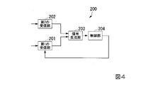
図4は、本発明の実施形態による受信機の最小構成を示す図である。
装置200は、第1の受信部201、第2の受信部202、信号生成部203、制御部204を備える。
第1の受信部201は、受けた信号の位相及び振幅を調整し第1の信号を生成する第1の調整手段を備える。第2の受信部202は、受けた信号の位相及び振幅を調整し第2の信号を生成する第2の調整手段を備える。信号生成部203は、第1の信号と第2の信号とに基づいて第3の信号を生成する。制御部204は、第3の信号に基づいて、第1の調整手段を制御する。
FIG. 4 is a diagram showing the minimum configuration of a receiver according to an embodiment of the invention.
The
The
なお、本発明の実施形態における処理は、適切な処理が行われる範囲において、処理の順番が入れ替わってもよい。
具体的には、例えば、図1に示した送受信機1において、移相器102aと可変利得増幅器103aとによって構成される移相・増幅器は、移相した後に増幅するものとして説明した。また、図1に示した送受信機1において、移相器105aと可変利得増幅器104aとによって構成される移相・増幅器は、増幅した後に移相するものとして説明した。しかしながら、本発明の別の実施形態では、移相・増幅器における移相と増幅の処理の順番は、移相した後に増幅してもよいし、増幅した後に移相してもよい。
It should be noted that the order of the processes in the embodiment of the present invention may be changed as long as appropriate processes are performed.
Specifically, for example, in the transmitter/
本発明の実施形態における記憶部、その他の記憶装置のそれぞれは、適切な情報の送受信が行われる範囲においてどこに備えられていてもよい。また、記憶部、その他の記憶装置のそれぞれは、適切な情報の送受信が行われる範囲において複数存在しデータを分散して記憶していてもよい。 Each of the storage unit and other storage devices in the embodiments of the present invention may be provided anywhere as long as appropriate information transmission/reception is performed. Further, each of the storage unit and other storage devices may exist in a plurality and store data in a distributed manner within a range where appropriate information transmission/reception is performed.
本発明の実施形態について説明したが、上述の信号処理部50、その他の制御装置は内部に、コンピュータシステムを有していてもよい。そして、上述した処理の過程は、プログラムの形式でコンピュータ読み取り可能な記録媒体に記憶されており、このプログラムをコンピュータが読み出して実行することによって、上記処理が行われる。コンピュータの具体例を以下に示す。
図5は、少なくとも1つの実施形態に係るコンピュータの構成を示す概略ブロック図である。
コンピュータ5は、図5に示すように、CPU6、メインメモリ7、ストレージ8、インターフェース9を備える。
例えば、上述の信号処理部50、その他の制御装置のそれぞれは、コンピュータ5に実装される。そして、上述した各処理部の動作は、プログラムの形式でストレージ8に記憶されている。CPU6は、プログラムをストレージ8から読み出してメインメモリ7に展開し、当該プログラムに従って上記処理を実行する。また、CPU6は、プログラムに従って、上述した各記憶部に対応する記憶領域をメインメモリ7に確保する。
Although the embodiments of the present invention have been described, the
FIG. 5 is a schematic block diagram showing the configuration of a computer according to at least one embodiment.
The
For example, the
ストレージ8の例としては、HDD(Hard Disk Drive)、SSD(Solid State Drive)、磁気ディスク、光磁気ディスク、CD-ROM(Compact Disc Read Only Memory)、DVD-ROM(Digital Versatile Disc Read Only Memory)、半導体メモリ等が挙げられる。ストレージ8は、コンピュータ5のバスに直接接続された内部メディアであってもよいし、インターフェース9または通信回線を介してコンピュータ5に接続される外部メディアであってもよい。また、このプログラムが通信回線によってコンピュータ5に配信される場合、配信を受けたコンピュータ5が当該プログラムをメインメモリ7に展開し、上記処理を実行してもよい。少なくとも1つの実施形態において、ストレージ8は、一時的でない有形の記憶媒体である。
Examples of the
また、上記プログラムは、前述した機能の一部を実現してもよい。さらに、上記プログラムは、前述した機能をコンピュータシステムにすでに記録されているプログラムとの組み合わせで実現できるファイル、いわゆる差分ファイル(差分プログラム)であってもよい。 Further, the program may implement part of the functions described above. Furthermore, the program may be a file capable of realizing the above functions in combination with a program already recorded in the computer system, that is, a so-called difference file (difference program).
本発明のいくつかの実施形態を説明したが、これらの実施形態は、例であり、発明の範囲を限定しない。これらの実施形態は、発明の要旨を逸脱しない範囲で、種々の追加、省略、置き換え、変更を行ってよい。 While several embodiments of the invention have been described, these embodiments are examples and do not limit the scope of the invention. Various additions, omissions, replacements, and modifications may be made to these embodiments without departing from the scope of the invention.
1・・・送受信機
5・・・コンピュータ
6・・・CPU
7・・・メインメモリ
8・・・ストレージ
9・・・インターフェース
10a・・・送受信部
20a・・・位相・振幅比較器
30・・・制御部
40・・・合成器
50・・・信号処理部
60、100・・・分配器
70a、80a、106a・・・スイッチ
101a・・・アンテナ
102a、105a・・・移相器
103a、104a・・・増幅器
107a・・・単極双投スイッチ
108a、109a・・・ミキサ
1 transmitter/
7
Claims (3)
受けた信号の位相及び振幅を調整し調整後の信号を出力する第1の調整手段を含む第1の受信部と、
受けた信号の位相及び振幅を調整し調整後の信号を出力する第2の調整手段を含む第2の受信部と、
受けた信号の位相及び振幅を調整し調整後の信号を出力する第3の調整手段を含む第1の送信部と、
受けた信号の位相及び振幅を調整し調整後の信号を出力する第4の調整手段を含む第2の送信部と、
前記比較結果に基づいて、前記第1の調整手段、前記第2の調整手段、前記第3の調整手段、及び前記第4の調整手段を調整する制御部と、
第1のタイミングにおいて前記第3の調整手段と前記第1の調整手段とを接続して第1の装置内経路を形成すると共に前記第4の調整手段と前記第2の調整手段とを接続して第2の装置内経路を形成することによって前記第1の装置内経路を通過した校正信号を前記第1の入力信号とし前記第2の装置内経路を通過した校正信号を前記第2の入力信号とする一方、第2のタイミングにおいて前記第3の調整手段と前記第2の調整手段とを接続して第3の装置内経路を形成すると共に前記第4の調整手段と前記第1の調整手段とを接続して第4の装置内経路を形成することによって前記第3の装置内経路を通過した校正信号を前記第1の入力信号とし前記第4の装置内経路を通過した校正信号を前記第2の入力信号とするスイッチ手段と、
を具備する装置。 comparison means for comparing the first input signal and the second input signal and outputting a comparison result;
a first receiver including a first adjusting means for adjusting the phase and amplitude of the received signal and outputting the adjusted signal ;
a second receiver including a second adjusting means for adjusting the phase and amplitude of the received signal and outputting the adjusted signal ;
a first transmitter including a third adjusting means for adjusting the phase and amplitude of the received signal and outputting the adjusted signal;
a second transmitter including fourth adjusting means for adjusting the phase and amplitude of the received signal and outputting the adjusted signal;
a control unit that adjusts the first adjustment means, the second adjustment means, the third adjustment means, and the fourth adjustment means based on the comparison result;
At a first timing, the third adjusting means and the first adjusting means are connected to form a first intra-apparatus path, and the fourth adjusting means and the second adjusting means are connected. forming a second intra-apparatus path by using the calibration signal that has passed through the first intra-apparatus path as the first input signal and the calibration signal that has passed through the second intra-apparatus path as the second input signal signal, at the second timing, the third adjusting means and the second adjusting means are connected to form a third intra-apparatus path, and the fourth adjusting means and the first adjusting means are connected at the second timing. forming a fourth intra-apparatus path by connecting means to form a calibration signal passing through the third intra-apparatus path as the first input signal and a calibration signal passing through the fourth intra-apparatus path as the first input signal; switch means for the second input signal;
A device comprising
第1のタイミングにおいて前記第3の調整手段と前記第1の調整手段とを接続して第1の装置内経路を形成すると共に前記第4の調整手段と前記第2の調整手段とを接続して第2の装置内経路を形成することによって前記第1の装置内経路を通過した校正信号を前記第1の入力信号とし前記第2の装置内経路を通過した校正信号を前記第2の入力信号とし、
第2のタイミングにおいて前記第3の調整手段と前記第2の調整手段とを接続して第3の装置内経路を形成すると共に前記第4の調整手段と前記第1の調整手段とを接続して第4の装置内経路を形成することによって前記第3の装置内経路を通過した校正信号を前記第1の入力信号とし前記第4の装置内経路を通過した校正信号を前記第2の入力信号とする、
装置による制御方法。 a comparison means for comparing a first input signal and a second input signal and outputting the comparison result; and a first adjustment means for adjusting the phase and amplitude of the received signal and outputting the adjusted signal. 1 receiving unit, a second receiving unit including second adjusting means for adjusting the phase and amplitude of the received signal and outputting the adjusted signal, and adjusting the phase and amplitude of the received signal and adjusting the adjusted signal a first transmission section including third adjustment means for outputting a signal; a second transmission section including fourth adjustment means for adjusting the phase and amplitude of the received signal and outputting the adjusted signal; a control unit that adjusts the first adjustment means, the second adjustment means, the third adjustment means, and the fourth adjustment means based on the comparison result; A control method by a device comprising
At a first timing, the third adjusting means and the first adjusting means are connected to form a first intra-apparatus path, and the fourth adjusting means and the second adjusting means are connected. forming a second intra-apparatus path by using the calibration signal that has passed through the first intra-apparatus path as the first input signal and the calibration signal that has passed through the second intra-apparatus path as the second input signal signal and
At a second timing, the third adjusting means and the second adjusting means are connected to form a third intra-apparatus path, and the fourth adjusting means and the first adjusting means are connected. forming a fourth intra-apparatus path by using the calibration signal that has passed through the third intra-apparatus path as the first input signal and the calibration signal that has passed through the fourth intra-apparatus path as the second input signal signal,
Control method by device.
第1のタイミングにおいて前記第3の調整手段と前記第1の調整手段とを接続して第1の装置内経路を形成すると共に前記第4の調整手段と前記第2の調整手段とを接続して第2の装置内経路を形成することによって前記第1の装置内経路を通過した校正信号を前記第1の入力信号とし前記第2の装置内経路を通過した校正信号を前記第2の入力信号とし、
第2のタイミングにおいて前記第3の調整手段と前記第2の調整手段とを接続して第3の装置内経路を形成すると共に前記第4の調整手段と前記第1の調整手段とを接続して第4の装置内経路を形成することによって前記第3の装置内経路を通過した校正信号を前記第1の入力信号とし前記第4の装置内経路を通過した校正信号を前記第2の入力信号とすること、
を実行させるプログラム。 a comparison means for comparing a first input signal and a second input signal and outputting the comparison result; and a first adjustment means for adjusting the phase and amplitude of the received signal and outputting the adjusted signal. 1 receiving unit, a second receiving unit including second adjusting means for adjusting the phase and amplitude of the received signal and outputting the adjusted signal, and adjusting the phase and amplitude of the received signal and adjusting the adjusted signal a first transmission section including third adjustment means for outputting a signal; a second transmission section including fourth adjustment means for adjusting the phase and amplitude of the received signal and outputting the adjusted signal; a control unit that adjusts the first adjusting means, the second adjusting means, the third adjusting means, and the fourth adjusting means based on the result; to the computer of the device comprising
At a first timing, the third adjusting means and the first adjusting means are connected to form a first intra-apparatus path, and the fourth adjusting means and the second adjusting means are connected. forming a second intra-apparatus path by using the calibration signal that has passed through the first intra-apparatus path as the first input signal and the calibration signal that has passed through the second intra-apparatus path as the second input signal signal and
At a second timing, the third adjusting means and the second adjusting means are connected to form a third intra-apparatus path, and the fourth adjusting means and the first adjusting means are connected. forming a fourth intra-apparatus path by using the calibration signal that has passed through the third intra-apparatus path as the first input signal and the calibration signal that has passed through the fourth intra-apparatus path as the second input signal signalthing,
program to run.
Priority Applications (2)
| Application Number | Priority Date | Filing Date | Title |
|---|---|---|---|
| JP2018046922A JP7124360B2 (en) | 2018-03-14 | 2018-03-14 | Device, control method and program by device |
| US16/394,588 US10637522B2 (en) | 2018-03-14 | 2019-04-25 | Apparatus, control method, and non-transitory computer readable medium storing program |
Applications Claiming Priority (1)
| Application Number | Priority Date | Filing Date | Title |
|---|---|---|---|
| JP2018046922A JP7124360B2 (en) | 2018-03-14 | 2018-03-14 | Device, control method and program by device |
Publications (2)
| Publication Number | Publication Date |
|---|---|
| JP2019161489A JP2019161489A (en) | 2019-09-19 |
| JP7124360B2 true JP7124360B2 (en) | 2022-08-24 |
Family
ID=67992772
Family Applications (1)
| Application Number | Title | Priority Date | Filing Date |
|---|---|---|---|
| JP2018046922A Active JP7124360B2 (en) | 2018-03-14 | 2018-03-14 | Device, control method and program by device |
Country Status (2)
| Country | Link |
|---|---|
| US (1) | US10637522B2 (en) |
| JP (1) | JP7124360B2 (en) |
Families Citing this family (3)
| Publication number | Priority date | Publication date | Assignee | Title |
|---|---|---|---|---|
| US10756798B2 (en) * | 2016-08-04 | 2020-08-25 | Telefonaktiebolaget Lm Ericsson (Publ) | Method and transmitter for transmit beamforming in a wireless communication system |
| EP3557786A1 (en) * | 2018-04-16 | 2019-10-23 | Samsung Electronics Co., Ltd. | Method of testing rf integrated circuit |
| JP7146150B2 (en) * | 2020-09-10 | 2022-10-03 | 三菱電機株式会社 | OUTPUT SIGNAL GENERATOR, CONTROL CIRCUIT, STORAGE MEDIUM AND PHASE CORRECTION METHOD |
Citations (1)
| Publication number | Priority date | Publication date | Assignee | Title |
|---|---|---|---|---|
| WO2017146020A1 (en) | 2016-02-23 | 2017-08-31 | 三菱電機株式会社 | Array antenna device and calibration method therefor |
Family Cites Families (8)
| Publication number | Priority date | Publication date | Assignee | Title |
|---|---|---|---|---|
| JPS59230334A (en) * | 1983-06-13 | 1984-12-24 | Fujitsu Ltd | Space diversity reception system |
| US6346910B1 (en) * | 1999-04-07 | 2002-02-12 | Tei Ito | Automatic array calibration scheme for wireless point-to-multipoint communication networks |
| JP3374834B2 (en) | 2000-05-23 | 2003-02-10 | 日本電気株式会社 | Phased array radar monitoring system |
| US8254306B2 (en) * | 2004-10-06 | 2012-08-28 | Broadcom Corporation | Method and system for implementing a single weight spatial multiplexing (SM) MIMO system |
| US8155610B2 (en) * | 2008-05-30 | 2012-04-10 | Silicon Laboratories Inc. | Combining multiple frequency modulation (FM) signals in a receiver |
| CN106063135B (en) * | 2014-03-07 | 2019-04-23 | 华为技术有限公司 | For interfering the device and method eliminated |
| EP3285402B1 (en) | 2015-04-13 | 2021-12-01 | Mitsubishi Electric Corporation | Phased array antenna device |
| WO2017150047A1 (en) * | 2016-03-04 | 2017-09-08 | 株式会社日立国際電気 | Reception device, and transmission/reception device |
-
2018
- 2018-03-14 JP JP2018046922A patent/JP7124360B2/en active Active
-
2019
- 2019-04-25 US US16/394,588 patent/US10637522B2/en active Active
Patent Citations (1)
| Publication number | Priority date | Publication date | Assignee | Title |
|---|---|---|---|---|
| WO2017146020A1 (en) | 2016-02-23 | 2017-08-31 | 三菱電機株式会社 | Array antenna device and calibration method therefor |
Non-Patent Citations (1)
| Title |
|---|
| 望月 拓志,第5世代移動通信システム用低SHF帯超多素子アクティブアンテナの開発,電子情報通信学会2016年通信ソサイエティ大会講演論文集1,2016年09月06日 |
Also Published As
| Publication number | Publication date |
|---|---|
| JP2019161489A (en) | 2019-09-19 |
| US20190363744A1 (en) | 2019-11-28 |
| US10637522B2 (en) | 2020-04-28 |
Similar Documents
| Publication | Publication Date | Title |
|---|---|---|
| US11411311B2 (en) | System and method for measuring a plurality of RF signal paths | |
| CN112385086B (en) | Method and apparatus for calibrating phased array antenna | |
| KR101240438B1 (en) | Calibrating radiofrequency paths of a phased-array antenna | |
| US9948407B2 (en) | Method and apparatus for beamforming calibration in point to multipoint communication systems | |
| US11522501B2 (en) | Phased array amplifier linearization | |
| JP7124360B2 (en) | Device, control method and program by device | |
| JP5815448B2 (en) | Phased array transmitter | |
| WO2013018365A1 (en) | Phased array transmission device | |
| US9287960B2 (en) | Radio communication apparatus, transmitter, and radio communication method | |
| US11349208B2 (en) | Antenna apparatus with switches for antenna array calibration | |
| US9899736B2 (en) | Low cost active antenna system | |
| Shimura et al. | Millimeter-wave TX phased array with phase adjusting function between transmitters for hybrid beamforming with interleaved subarrays | |
| CN112368957B (en) | Phase calibration method, related device and equipment | |
| JP6532017B2 (en) | Phased array transmitter | |
| JP4025236B2 (en) | Array antenna communication device | |
| KR20200080592A (en) | Multiple antenna system for calibration of signal amplitude and phase with high-resolution in the RF millimeter-wave | |
| US11367953B2 (en) | Antenna device and calibration method | |
| US11973473B2 (en) | Phased array amplifier linearization | |
| US10284271B1 (en) | Method, system and device for providing phase shifted signals to an array of antennas for beam steering | |
| JP2024057410A (en) | Array Antenna Device | |
| KR20160080031A (en) | Apparatus and method for transmitting path calibration | |
| JP2006319511A (en) | Transmission system and its receiver | |
| JP2005150958A (en) | Array antenna |
Legal Events
| Date | Code | Title | Description |
|---|---|---|---|
| RD01 | Notification of change of attorney |
Free format text: JAPANESE INTERMEDIATE CODE: A7421 Effective date: 20190610 |
|
| A521 | Request for written amendment filed |
Free format text: JAPANESE INTERMEDIATE CODE: A821 Effective date: 20190610 |
|
| A621 | Written request for application examination |
Free format text: JAPANESE INTERMEDIATE CODE: A621 Effective date: 20210204 |
|
| A131 | Notification of reasons for refusal |
Free format text: JAPANESE INTERMEDIATE CODE: A131 Effective date: 20211221 |
|
| A977 | Report on retrieval |
Free format text: JAPANESE INTERMEDIATE CODE: A971007 Effective date: 20211222 |
|
| A521 | Request for written amendment filed |
Free format text: JAPANESE INTERMEDIATE CODE: A523 Effective date: 20220221 |
|
| TRDD | Decision of grant or rejection written | ||
| A01 | Written decision to grant a patent or to grant a registration (utility model) |
Free format text: JAPANESE INTERMEDIATE CODE: A01 Effective date: 20220712 |
|
| A61 | First payment of annual fees (during grant procedure) |
Free format text: JAPANESE INTERMEDIATE CODE: A61 Effective date: 20220725 |
|
| R151 | Written notification of patent or utility model registration |
Ref document number: 7124360 Country of ref document: JP Free format text: JAPANESE INTERMEDIATE CODE: R151 |