JP7121908B2 - power system - Google Patents
power system Download PDFInfo
- Publication number
- JP7121908B2 JP7121908B2 JP2018222765A JP2018222765A JP7121908B2 JP 7121908 B2 JP7121908 B2 JP 7121908B2 JP 2018222765 A JP2018222765 A JP 2018222765A JP 2018222765 A JP2018222765 A JP 2018222765A JP 7121908 B2 JP7121908 B2 JP 7121908B2
- Authority
- JP
- Japan
- Prior art keywords
- sweep
- module
- battery module
- battery
- string
- Prior art date
- Legal status (The legal status is an assumption and is not a legal conclusion. Google has not performed a legal analysis and makes no representation as to the accuracy of the status listed.)
- Active
Links
Images


Classifications
-
- H—ELECTRICITY
- H02—GENERATION; CONVERSION OR DISTRIBUTION OF ELECTRIC POWER
- H02M—APPARATUS FOR CONVERSION BETWEEN AC AND AC, BETWEEN AC AND DC, OR BETWEEN DC AND DC, AND FOR USE WITH MAINS OR SIMILAR POWER SUPPLY SYSTEMS; CONVERSION OF DC OR AC INPUT POWER INTO SURGE OUTPUT POWER; CONTROL OR REGULATION THEREOF
- H02M3/00—Conversion of DC power input into DC power output
- H02M3/02—Conversion of DC power input into DC power output without intermediate conversion into AC
- H02M3/04—Conversion of DC power input into DC power output without intermediate conversion into AC by static converters
- H02M3/10—Conversion of DC power input into DC power output without intermediate conversion into AC by static converters using discharge tubes with control electrode or semiconductor devices with control electrode
- H02M3/145—Conversion of DC power input into DC power output without intermediate conversion into AC by static converters using discharge tubes with control electrode or semiconductor devices with control electrode using devices of a triode or transistor type requiring continuous application of a control signal
- H02M3/155—Conversion of DC power input into DC power output without intermediate conversion into AC by static converters using discharge tubes with control electrode or semiconductor devices with control electrode using devices of a triode or transistor type requiring continuous application of a control signal using semiconductor devices only
- H02M3/156—Conversion of DC power input into DC power output without intermediate conversion into AC by static converters using discharge tubes with control electrode or semiconductor devices with control electrode using devices of a triode or transistor type requiring continuous application of a control signal using semiconductor devices only with automatic control of output voltage or current, e.g. switching regulators
- H02M3/158—Conversion of DC power input into DC power output without intermediate conversion into AC by static converters using discharge tubes with control electrode or semiconductor devices with control electrode using devices of a triode or transistor type requiring continuous application of a control signal using semiconductor devices only with automatic control of output voltage or current, e.g. switching regulators including plural semiconductor devices as final control devices for a single load
- H02M3/1584—Conversion of DC power input into DC power output without intermediate conversion into AC by static converters using discharge tubes with control electrode or semiconductor devices with control electrode using devices of a triode or transistor type requiring continuous application of a control signal using semiconductor devices only with automatic control of output voltage or current, e.g. switching regulators including plural semiconductor devices as final control devices for a single load with a plurality of power processing stages connected in parallel
-
- H—ELECTRICITY
- H02—GENERATION; CONVERSION OR DISTRIBUTION OF ELECTRIC POWER
- H02J—ELECTRIC POWER NETWORKS; CIRCUIT ARRANGEMENTS OR SYSTEMS FOR SUPPLYING OR DISTRIBUTING ELECTRIC POWER; SYSTEMS FOR STORING ELECTRIC ENERGY
- H02J1/00—Circuit arrangements for DC mains or DC distribution networks
- H02J1/10—Parallel operation of DC sources
- H02J1/102—Parallel operation of DC sources being switching converters
-
- H—ELECTRICITY
- H02—GENERATION; CONVERSION OR DISTRIBUTION OF ELECTRIC POWER
- H02J—ELECTRIC POWER NETWORKS; CIRCUIT ARRANGEMENTS OR SYSTEMS FOR SUPPLYING OR DISTRIBUTING ELECTRIC POWER; SYSTEMS FOR STORING ELECTRIC ENERGY
- H02J7/00—Circuit arrangements for charging or discharging batteries or for supplying loads from batteries
- H02J7/02—Circuit arrangements for charging or discharging batteries or for supplying loads from batteries for charging batteries from AC mains by converters
- H02J7/04—Regulation of charging current or voltage
- H02J7/06—Regulation of charging current or voltage using discharge tubes or semiconductor devices
-
- H—ELECTRICITY
- H02—GENERATION; CONVERSION OR DISTRIBUTION OF ELECTRIC POWER
- H02J—ELECTRIC POWER NETWORKS; CIRCUIT ARRANGEMENTS OR SYSTEMS FOR SUPPLYING OR DISTRIBUTING ELECTRIC POWER; SYSTEMS FOR STORING ELECTRIC ENERGY
- H02J7/00—Circuit arrangements for charging or discharging batteries or for supplying loads from batteries
- H02J7/50—Circuit arrangements for charging or discharging batteries or for supplying loads from batteries acting upon multiple batteries simultaneously or sequentially
- H02J7/52—Circuit arrangements for charging or discharging batteries or for supplying loads from batteries acting upon multiple batteries simultaneously or sequentially for charge balancing, e.g. equalisation of charge between batteries
- H02J7/56—Active balancing, e.g. using capacitor-based, inductor-based or DC-DC converters
-
- H—ELECTRICITY
- H02—GENERATION; CONVERSION OR DISTRIBUTION OF ELECTRIC POWER
- H02M—APPARATUS FOR CONVERSION BETWEEN AC AND AC, BETWEEN AC AND DC, OR BETWEEN DC AND DC, AND FOR USE WITH MAINS OR SIMILAR POWER SUPPLY SYSTEMS; CONVERSION OF DC OR AC INPUT POWER INTO SURGE OUTPUT POWER; CONTROL OR REGULATION THEREOF
- H02M3/00—Conversion of DC power input into DC power output
- H02M3/02—Conversion of DC power input into DC power output without intermediate conversion into AC
- H02M3/04—Conversion of DC power input into DC power output without intermediate conversion into AC by static converters
- H02M3/10—Conversion of DC power input into DC power output without intermediate conversion into AC by static converters using discharge tubes with control electrode or semiconductor devices with control electrode
- H02M3/145—Conversion of DC power input into DC power output without intermediate conversion into AC by static converters using discharge tubes with control electrode or semiconductor devices with control electrode using devices of a triode or transistor type requiring continuous application of a control signal
- H02M3/155—Conversion of DC power input into DC power output without intermediate conversion into AC by static converters using discharge tubes with control electrode or semiconductor devices with control electrode using devices of a triode or transistor type requiring continuous application of a control signal using semiconductor devices only
- H02M3/156—Conversion of DC power input into DC power output without intermediate conversion into AC by static converters using discharge tubes with control electrode or semiconductor devices with control electrode using devices of a triode or transistor type requiring continuous application of a control signal using semiconductor devices only with automatic control of output voltage or current, e.g. switching regulators
- H02M3/158—Conversion of DC power input into DC power output without intermediate conversion into AC by static converters using discharge tubes with control electrode or semiconductor devices with control electrode using devices of a triode or transistor type requiring continuous application of a control signal using semiconductor devices only with automatic control of output voltage or current, e.g. switching regulators including plural semiconductor devices as final control devices for a single load
-
- H—ELECTRICITY
- H02—GENERATION; CONVERSION OR DISTRIBUTION OF ELECTRIC POWER
- H02M—APPARATUS FOR CONVERSION BETWEEN AC AND AC, BETWEEN AC AND DC, OR BETWEEN DC AND DC, AND FOR USE WITH MAINS OR SIMILAR POWER SUPPLY SYSTEMS; CONVERSION OF DC OR AC INPUT POWER INTO SURGE OUTPUT POWER; CONTROL OR REGULATION THEREOF
- H02M1/00—Details of apparatus for conversion
- H02M1/0067—Converter structures employing plural converter units, other than for parallel operation of the units on a single load
- H02M1/0077—Plural converter units whose outputs are connected in series
-
- H—ELECTRICITY
- H02—GENERATION; CONVERSION OR DISTRIBUTION OF ELECTRIC POWER
- H02M—APPARATUS FOR CONVERSION BETWEEN AC AND AC, BETWEEN AC AND DC, OR BETWEEN DC AND DC, AND FOR USE WITH MAINS OR SIMILAR POWER SUPPLY SYSTEMS; CONVERSION OF DC OR AC INPUT POWER INTO SURGE OUTPUT POWER; CONTROL OR REGULATION THEREOF
- H02M3/00—Conversion of DC power input into DC power output
- H02M3/02—Conversion of DC power input into DC power output without intermediate conversion into AC
- H02M3/04—Conversion of DC power input into DC power output without intermediate conversion into AC by static converters
- H02M3/10—Conversion of DC power input into DC power output without intermediate conversion into AC by static converters using discharge tubes with control electrode or semiconductor devices with control electrode
- H02M3/145—Conversion of DC power input into DC power output without intermediate conversion into AC by static converters using discharge tubes with control electrode or semiconductor devices with control electrode using devices of a triode or transistor type requiring continuous application of a control signal
- H02M3/155—Conversion of DC power input into DC power output without intermediate conversion into AC by static converters using discharge tubes with control electrode or semiconductor devices with control electrode using devices of a triode or transistor type requiring continuous application of a control signal using semiconductor devices only
- H02M3/156—Conversion of DC power input into DC power output without intermediate conversion into AC by static converters using discharge tubes with control electrode or semiconductor devices with control electrode using devices of a triode or transistor type requiring continuous application of a control signal using semiconductor devices only with automatic control of output voltage or current, e.g. switching regulators
- H02M3/158—Conversion of DC power input into DC power output without intermediate conversion into AC by static converters using discharge tubes with control electrode or semiconductor devices with control electrode using devices of a triode or transistor type requiring continuous application of a control signal using semiconductor devices only with automatic control of output voltage or current, e.g. switching regulators including plural semiconductor devices as final control devices for a single load
- H02M3/1584—Conversion of DC power input into DC power output without intermediate conversion into AC by static converters using discharge tubes with control electrode or semiconductor devices with control electrode using devices of a triode or transistor type requiring continuous application of a control signal using semiconductor devices only with automatic control of output voltage or current, e.g. switching regulators including plural semiconductor devices as final control devices for a single load with a plurality of power processing stages connected in parallel
- H02M3/1586—Conversion of DC power input into DC power output without intermediate conversion into AC by static converters using discharge tubes with control electrode or semiconductor devices with control electrode using devices of a triode or transistor type requiring continuous application of a control signal using semiconductor devices only with automatic control of output voltage or current, e.g. switching regulators including plural semiconductor devices as final control devices for a single load with a plurality of power processing stages connected in parallel switched with a phase shift, i.e. interleaved
-
- Y—GENERAL TAGGING OF NEW TECHNOLOGICAL DEVELOPMENTS; GENERAL TAGGING OF CROSS-SECTIONAL TECHNOLOGIES SPANNING OVER SEVERAL SECTIONS OF THE IPC; TECHNICAL SUBJECTS COVERED BY FORMER USPC CROSS-REFERENCE ART COLLECTIONS [XRACs] AND DIGESTS
- Y02—TECHNOLOGIES OR APPLICATIONS FOR MITIGATION OR ADAPTATION AGAINST CLIMATE CHANGE
- Y02T—CLIMATE CHANGE MITIGATION TECHNOLOGIES RELATED TO TRANSPORTATION
- Y02T10/00—Road transport of goods or passengers
- Y02T10/60—Other road transportation technologies with climate change mitigation effect
- Y02T10/70—Energy storage systems for electromobility, e.g. batteries
Landscapes
- Engineering & Computer Science (AREA)
- Power Engineering (AREA)
- Charge And Discharge Circuits For Batteries Or The Like (AREA)
- Secondary Cells (AREA)
Description
本発明は、電池と回路を含むモジュールを複数備えた電源システムに関する。 The present invention relates to a power supply system having a plurality of modules containing batteries and circuits.
電池と回路を含むモジュールを複数備え、複数のモジュールの各々を制御することで、外部への電力の出力、および、外部から入力される電力の蓄電の少なくともいずれかを行う電源装置が知られている。例えば、特許文献1に記載されている電源装置は、電池、第1のスイッチング素子、および第2のスイッチング素子を含む電池回路モジュールを複数備える。複数の電池回路モジュールは、各々の出力端子を介して直列に接続されている。電源装置の制御回路は、第1のスイッチング素子および第2のスイッチング素子をオンオフ駆動するゲート信号を、各々の電池回路モジュールに対して一定時間毎にそれぞれ出力する。これにより、複数の電池回路モジュールから目標とする電力を出力する。
A power supply device is known that includes a plurality of modules each including a battery and a circuit, and controls each of the plurality of modules to output power to the outside and/or store power input from the outside. there is For example, the power supply device described in
各々の電池回路モジュールにおけるスイッチング素子が、微小時間毎に切り替えられていくと、各々の電池回路モジュールでリンギングが発生し、電池回路モジュールにおける電流値が高周波で振動する場合がある。この場合、電池回路モジュールが備える電池の発熱量が増加する可能性、および、電池電圧の検出精度が低下する可能性が高くなる。従って、電池および回路を備えた各々のモジュールで発生し得るリンギングの影響を抑制できることが望ましい。 When the switching elements in each battery circuit module are switched every minute time, ringing occurs in each battery circuit module, and the current value in the battery circuit module may oscillate at a high frequency. In this case, there is a high possibility that the amount of heat generated by the battery included in the battery circuit module will increase, and that the detection accuracy of the battery voltage will decrease. Therefore, it is desirable to be able to suppress the effects of ringing that can occur in each module that includes a battery and circuitry.
本発明の典型的な目的は、電池および回路を備えた各々のモジュールで発生し得るリンギングの影響を適切に抑制することが可能な電源システムを提供することである。 A typical object of the present invention is to provide a power supply system capable of appropriately suppressing the effects of ringing that may occur in each module including batteries and circuits.
かかる目的を実現するべく、ここに開示される一態様の電源システムは、メインラインと、該メインラインに接続された複数のスイープモジュールと、を有し、上記スイープモジュールは、少なくとも1つの電池を含む電池モジュールと、該電池モジュールを上記メインラインに接続するように構成された入出力回路と、当該入出力回路に配置され、上記電池モジュールと上記メインラインとの接続および切断を切り替える、少なくとも1つのスイッチング素子と、上記入出力回路に、上記電池モジュールと並列に取り付けられたコンデンサと、上記入出力回路と上記電池モジュールを接続する配線と、を有し、上記複数のスイープモジュールは、上記スイッチング素子のオンとオフの交互駆動を制御するゲート信号を、定められた遅延時間毎に順に各々の前記電力回路モジュールに出力することで、上記メインラインに接続する上記電池モジュールを順次切り替えるスイープ制御を実行するように構成されており、上記配線は、ループが形成された状態で維持されたことを特徴とする。 In order to achieve such an object, one aspect of the power supply system disclosed herein has a main line and a plurality of sweep modules connected to the main line, wherein the sweep module includes at least one battery. an input/output circuit configured to connect the battery module to the main line; and an input/output circuit arranged in the input/output circuit for switching connection and disconnection between the battery module and the main line. a capacitor mounted in parallel with the battery module in the input/output circuit; and wiring connecting the input/output circuit and the battery module, and the plurality of sweep modules each include the switching element. Sweep control for sequentially switching the battery modules connected to the main line is performed by sequentially outputting a gate signal for controlling the alternate driving of elements on and off to each of the power circuit modules at predetermined delay times. and wherein the wiring is maintained in a looped state.
上記構成の電源システムは、メインラインに接続させるスイープモジュールを順次切り替えるスイープ制御を実行する。スイープ制御が実行されると、各々の電池モジュールでリンギングが発生し、電池モジュールにおける電流値が高周波で振動する場合がある。しかし、上記構成の電力回路モジュールでは、コンデンサと、配線に形成されたループ(以下、「ループ部」という)によって共振回路が形成される。スイープ制御におけるゲート信号の周波数(つまり、複数のスイープモジュールをスイッチングする際の周波数)と、共振回路のLC共振周波数とを、各電池モジュールのインピーダンス特性に応じて適合させることで、電池モジュールにおける電流が直流に近くなり、リンギングの影響が抑制される。また、共振回路を形成するインダクタとして、入出力回路と電池モジュールを接続する配線をループ状に形成したループ部が用いられる。従って、共振回路を形成するために各種素子または機器(例えばリアクトル等)が用いられる場合に比べて、電源システムの構成が簡素化される。よって、各々のスイープモジュールで発生し得るリンギングの影響が、適切に抑制される。 The power supply system configured as described above executes sweep control for sequentially switching the sweep modules to be connected to the main line. When sweep control is executed, ringing occurs in each battery module, and the current value in the battery module may oscillate at high frequencies. However, in the power circuit module configured as described above, a resonance circuit is formed by the capacitor and the loop formed in the wiring (hereinafter referred to as "loop portion"). By matching the frequency of the gate signal in the sweep control (that is, the frequency when switching a plurality of sweep modules) and the LC resonance frequency of the resonance circuit according to the impedance characteristics of each battery module, the current in the battery module becomes close to direct current, and the effect of ringing is suppressed. Also, as an inductor that forms a resonance circuit, a loop portion is used in which wiring that connects an input/output circuit and a battery module is formed in a loop shape. Therefore, the configuration of the power supply system is simplified compared to the case where various elements or devices (for example, reactors, etc.) are used to form the resonance circuit. Therefore, the influence of ringing that may occur in each sweep module is appropriately suppressed.
ここに開示される電源システムの好適な一態様では、入出力回路は、配線を繋ぐ第1端子を備える。配線は、第1端子に着脱可能に装着される第1配線端子を備える。この場合、作業者は、入出力回路の第1端子と配線の第1配線端子の着脱を行うことで、電池回路モジュールの入出力回路に装着する電池モジュールを適切に交換することができる。 In a preferred aspect of the power supply system disclosed herein, the input/output circuit includes a first terminal for connecting wiring. The wiring includes a first wiring terminal detachably attached to the first terminal. In this case, the operator can appropriately replace the battery module attached to the input/output circuit of the battery circuit module by attaching/detaching the first terminal of the input/output circuit and the first wiring terminal of the wiring.
ここに開示される電源システムの好適な一態様では、電池モジュールは、配線を繋ぐ第2端子を備える。配線は、第2端子に着脱可能に装着される第2配線端子を備える。この場合、作業者は、電池モジュールの第2端子と配線の第2配線端子の着脱を行うことで、電池回路モジュールの入出力回路に装着する電池モジュールを適切に交換することができる。 In a preferred aspect of the power supply system disclosed herein, the battery module includes a second terminal for connecting wiring. The wiring includes a second wiring terminal detachably attached to the second terminal. In this case, the operator can appropriately replace the battery module attached to the input/output circuit of the battery circuit module by attaching and detaching the second terminal of the battery module and the second wiring terminal of the wiring.
以下、本開示における典型的な実施形態の1つについて、図面を参照しつつ詳細に説明する。本明細書において特に言及している事項以外の事柄であって実施に必要な事柄は、当該分野における従来技術に基づく当業者の設計事項として把握され得る。本発明は、本明細書に開示されている内容と当該分野における技術常識とに基づいて実施することができる。なお、以下の図面においては、同じ作用を奏する部材・部位には同じ符号を付して説明している。また、各図における寸法関係は実際の寸法関係を反映するものではない。 One typical embodiment of the present disclosure will be described in detail below with reference to the drawings. Matters other than those specifically referred to in this specification that are necessary for implementation can be grasped as design matters for those skilled in the art based on the prior art in the relevant field. The present invention can be implemented based on the contents disclosed in this specification and common general technical knowledge in the field. In the drawings below, members and portions having the same function are denoted by the same reference numerals. Also, the dimensional relationships in each drawing do not reflect the actual dimensional relationships.
<全体の概略構成>
図1を参照して、本実施形態における電源システム1の全体構成について概略的に説明する。電源システム1は、上位の電力系統8に接続された配電装置5に対する電力の出力、および、配電装置5から入力される電力の蓄電の少なくともいずれか(以下、単に「電力の入出力」という場合もある)を行う。一例として、本実施形態では、配電装置5としてPCS(Power Conditioning Subsystem)が用いられている。PCSは、電力系統8から電源システム1等へ入力される電力および電源システム1等から電力系統8へ出力される電力を、電源システム1等と電力系統8との間で相互に変換する機能を有する。
<General configuration>
An overall configuration of a
電力系統8で電力が余った場合に、配電装置5は余剰の電力を電源システム1に出力する。この場合、電源システム1は、配電装置5から入力された電力を蓄電する。また、電源システム1は、上位の電力系統8を制御する上位システム6からの指示に応じて、電源システム1に蓄電されている電力を配電装置5に出力する。図1では、上位システム6は、電力系統8および配電装置5を制御するシステムとして、電力系統8および配電装置5とは別で設けられているように図示されている。しかし、上位システム6は、電力系統8または配電装置5に組み込まれていてもよい。
When the
電源システム1は、少なくとも1つのストリング10を備えている。本実施形態の電源システム1は、複数(N個:N≧2)のストリング10(10A,10B,・・・,10N)を備えている。図1では、便宜上、N個のストリング10のうち、2つのストリング10A,10Bのみを図示している。ストリング10は、配電装置5との間の電力の入出力の単位となる。複数のストリング10は、配電装置5に対して並列に接続されている。配電装置5と各々のストリング10の間の電力の入出力(通電)は、メインライン7を通じて行われる。
The
ストリング10は、SCU(String Control Unit)11、および、複数(M個:M≧2)のスイープモジュール20(20A,20B,・・・,20M)を備える。各々のスイープモジュール20は、電池および制御回路を備える。SCU11は、ストリング10毎に設けられている。SCU11は、1つのストリング10に含まれる複数のスイープモジュール20を統合制御するコントローラである。各々のSCU11は、電力制御装置としてのGCU(Group control Unit)2との間で通信を行う。GCU2は、複数のストリング10を含むグループ全体を統合制御するコントローラである。GCU2は、上位システム6および各々のSCU11との間で通信を行う。上位システム6、GCU2、およびSCU11の間の通信の方法には、種々の方法(例えば、有線通信、無線通信、ネットワークを介した通信等の少なくともいずれか)を採用できる。
The
なお、ストリング10およびスイープモジュール20等を制御するコントローラの構成を変更することも可能である。例えば、GCU2とSCU11が別々に設けられていなくてもよい。つまり、1つのコントローラが、少なくとも1つのストリング10を含むグループ全体と、ストリング10に含まれる複数のスイープモジュール20を共に制御してもよい。
It is also possible to change the configuration of the controller that controls the
<スイープモジュール>
図2を参照して、スイープモジュール20について詳細に説明する。スイープモジュール20は、電池モジュール30、電力回路モジュール40、およびスイープユニット(SU(Sweep Unit))50を備える。
<Sweep module>
The
電池モジュール30は、少なくとも1つの電池31を備えている。本実施形態の電池モジュール30には、複数の電池31が設けられている。複数の電池31は直列に接続されている。本実施形態では、電池31として二次電池が使用されている。電池31には、種々の二次電池(例えば、ニッケル水素電池、リチウムイオン電池、ニッケルカドミウム電池等)の少なくともいずれかを使用できる。なお、電源システム1において、複数種類の電池31を混在させることも可能である。もちろん、全ての電池モジュール30内の電池31の種類が全て同じであってもよい。
電池モジュール30には、電圧検出部35および温度検出部36が装着されている。電圧検出部35は、電池モジュール30が備える電池31(本実施形態では、直列に接続された複数の電池31)の電圧を検出する。温度検出部36は、電池モジュール30が備える電池31の温度、または、電池31の近傍の温度を検出する。温度検出部36には、温度を検出する各種素子(例えばサーミスタ等)を使用できる。
A
電池モジュール30は、電力回路モジュール40に対して着脱可能に設けられている。詳細には、本実施形態では、複数の電池31を備えた電池モジュール30が1つの単位となって、電力回路モジュール40からの取り外し、および、電力回路モジュール40への装着が行われる。従って、電池モジュール30に含まれる電池31が1つずつ交換される場合に比べて、作業者が電池31を交換する際の作業工数が減少する。なお、本実施形態では、電圧検出部35および温度検出部36は、電池モジュール30とは別で交換される。しかし、電圧検出部35および温度検出部36の少なくとも一方が、電池モジュール30と共に交換されてもよい。
The
電力回路モジュール40は、電池モジュール30における電力の入出力を適切に実現させるための回路を形成する。本実施形態では、電力回路モジュール40は、電池モジュール30とメインライン7の間の接続および切り離しを切り替える少なくとも1つのスイッチング素子を備えている。本実施形態では、電力回路モジュール40は、電池モジュール30をメインライン7に接続するための入出力回路43と、入出力回路43に配置された第1スイッチング素子41および第2スイッチング素子42を備える。第1スイッチング素子41および第2スイッチング素子42は、スイープユニット50から入力される信号(例えばゲート信号等)に応じてスイッチング動作を行う。
The
本実施形態では、図2に示されているように、第1スイッチング素子41は、入出力回路43において、メインライン7に対して直列に、かつ、電池モジュール30に対して並列に取り付けられている。第2スイッチング素子42は、入出力回路43において、メインライン7に電池モジュール30を直列に接続する部分に取り付けられている。第1スイッチング素子41は、メインライン7に放電電流が流れる方向に沿って順方向となるように、ソースとドレインが配置される。第2スイッチング素子42は、メインライン7に電池モジュール30を直列に取り付ける入出力回路43において、電池モジュール30に充電電流が流れる方向に沿って順方向となるように、ソースとドレインが配置される。本実施形態では、第1スイッチング素子41と第2スイッチング素子42は、それぞれMOSFET(例えば、Si-MOSFET)であり、順方向に向いたボディダイオード41a,42aをそれぞれ備えている。ここで、第1スイッチング素子41のボディダイオード41aは、第1ボディダイオードと適宜に称されうる。第2スイッチング素子42のボディダイオード42aは、第2ボディダイオードと適宜に称される。
In this embodiment, as shown in FIG. 2, the
なお、第1スイッチング素子41と第2スイッチング素子42は、図2の例に限定されない。第1スイッチング素子41および第2スイッチング素子42には、導通と非導通を切り替えることが可能な種々の素子を使用することが可能である。本実施形態では、第1スイッチング素子41および第2スイッチング素子42の両方に、MOSFET(詳細にはSi-MOSFET)が使用されている。しかし、MOSFET以外の素子(例えば、トランジスタ等)が採用されてもよい。
Note that the
また、電力回路モジュール40は、インダクタ46およびコンデンサ47を備える。インダクタ46は、電池モジュール30と第2スイッチング素子42の間に設けられている。コンデンサ47は、電池モジュール30と並列に接続されている。本実施形態では、電池モジュール30の電池31に二次電池が使用されているので、内部抵抗損失の増加による電池31の劣化を抑制する必要がある。従って、電池モジュール30、インダクタ46、およびコンデンサ47によってRLCフィルタを形成することで、電流の平準化が図られている。
The
また、電力回路モジュール40には温度検出部48が設けられている。温度検出部48は、第1スイッチング素子41および第2スイッチング素子42の少なくとも一方の発熱を検出するために設けられている。本実施形態では、第1スイッチング素子41、第2スイッチング素子42、および温度検出部48は、1つの基盤に組み込まれている。従って、第1スイッチング素子41および第2スイッチング素子42の一方の故障が発見された時点で、基盤ごと交換される。よって、本実施形態では、1つの温度検出部48が第1スイッチング素子41および第2スイッチング素子42の近傍に設けられることで、部品点数が削減されている。ただし、第1スイッチング素子41の温度を検出する温度検出部と、第2スイッチング素子42の温度を検出する温度検出部が別々に設けられていてもよい。温度検出部48には、温度を検出する各種素子(例えばサーミスタ等)を使用できる。
Further, the
図1および図2に示すように、ストリング10内の複数の電池モジュール30は、それぞれ電力回路モジュール40を介在させてメインライン7に対して直列に接続されている。そして、電力回路モジュール40の第1スイッチング素子41と第2スイッチング素子42が適宜に制御されることによって、電池モジュール30はメインライン7に接続されたり、切り離されたりする。図2に示された電力回路モジュール40の構成例では、第1スイッチング素子41がオフとされ、且つ第2スイッチング素子42がオンとされると、電池モジュール30はメインライン7に接続される。第1スイッチング素子41がオンとされ、且つ第2スイッチング素子42がオフとされると、電池モジュール30はメインライン7から切り離される。
As shown in FIGS. 1 and 2, the plurality of
スイープユニット(SU(Sweep Unit))50は、スイープモジュール20に関する各種制御を行うようにスイープモジュール20に組み込まれた制御ユニットであり、スイープ制御ユニットとも称される。詳細には、スイープユニット50は、電力回路モジュール40における第1スイッチング素子41および第2スイッチング素子42を駆動させる信号を出力する。また、スイープユニット50は、スイープモジュール20の状態(例えば、電池モジュール30の電圧、電池31の温度、および、スイッチング素子41,42の温度等)を、上位のコントローラ(本実施形態では、図1に示すSCU11)に通知する。スイープユニット50は、ストリング10の複数のスイープモジュール20にそれぞれ組み込まれている。ストリング10の複数のスイープモジュール20に組み込まれたスイープユニット50は、順に繋がっており、SCU11から出力されたゲート信号GSを順に伝搬するように構成されている。図2に示されているように、本実施形態では、スイープユニット50は、SU処理部51、遅延/選択回路52、およびゲートドライバ53を備えている。
A sweep unit (SU (Sweep Unit)) 50 is a control unit incorporated in the
SU処理部51は、スイープユニット50における各種処理を司るコントローラである。SU処理部51には、例えばマイコン等を使用できる。SU処理部51には、電圧検出部35、温度検出部36、および温度検出部48からの検出信号が入力される。また、SU処理部51は、上位のコントローラ(本実施形態ではストリング10のSCU11)との間で各種信号の入出力を行う。
The SU processing unit 51 is a controller that controls various processes in the
SCU11からSU処理部51に入力される信号には、強制スルー信号CSS、および強制接続信号CCSが含まれる。強制スルー信号CSSは、配電装置5からストリング10に延びるメインライン7(図1参照)から、電池モジュール30を切り離すことを指示する信号である。つまり、強制スルー信号CSSが入力されたスイープモジュール20は、配電装置5との間で電力を入出力するための動作をスルーする。強制接続信号CCSは、メインライン7に対する電池モジュール30の接続の維持を指示する信号である。
Signals input from the
遅延/選択回路52にはゲート信号GSが入力される。ゲート信号(本実施形態ではPWM信号)GSは、第1スイッチング素子41および第2スイッチング素子42のオン状態とオフ状態の交互の繰り返しスイッチング動作を制御する信号である。ゲート信号GSは、オンとオフが交互に繰り返されるパルス状の信号である。ゲート信号GSは、まず、SCU11(図1参照)から、1つのスイープモジュール20内の遅延/選択回路52に入力される。次いで、ゲート信号GSは、1つのスイープモジュール20の遅延/選択回路52から、他のスイープモジュール20の遅延/選択回路52に順に伝播されていく。
A gate signal GS is input to the delay/
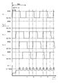
ストリング10では、図3および図4に例示するスイープ制御が実行される。ここで、図3は、スイープ動作におけるタイミングチャートの一例である。具体的には、図3には、全てのスイープモジュール20にスイープ動作を実行させた場合の、各スイープモジュール20の接続状態と、配電装置5に出力される電圧との関係が一例として示されている。図4は、強制スルー動作におけるタイミングチャートの一例である。具体的には、図4には、一部のスイープモジュール20に強制スルー動作を実行させた場合の、各スイープモジュール20の接続状態と、配電装置5に出力される電圧との関係が一例として示されている。
In
ストリング10において実行されるスイープ制御では、ストリング10に組み込まれた複数のスイープモジュール20(例えば、M個)のうち、同じタイミングでONになるスイープモジュール20の数mが定められる。スイープ制御でのゲート信号GSは、例えば、パルス波形で構成されている。ゲート信号GSは、例えば、メインライン7に電池モジュール30を接続するための信号波形と、電池モジュール30をメインライン7から切り離すための信号波形とを順に並べられているとよい。ゲート信号GSにおいて、メインライン7に電池モジュール30を接続するための信号波形は、ストリング10をスイープする予め定められた周期Tにおいて、メインライン7に接続する電池モジュール30の数が組み込まれているとよい。また、電池モジュール30をメインライン7から切り離すための信号波形は、ストリング10に組み込まれた電池モジュール30のうち、電池モジュール30をメインライン7から切り離すことが必要な所要数が組み込まれている。電池モジュール30をメインライン7から切り離すための信号波形や、電池モジュール30をメインライン7から切り離すための信号波形は、適宜に波長などが調整される。
In the sweep control executed in the
本実施形態のストリング10では、M個のスイープモジュール20が、配電装置5側からスイープモジュール20A,20B,・・・,20Mの順に直列に接続されている。以下では、配電装置5に近い側を上流側、配電装置5から遠い側を下流側とする。まず、ゲート信号GSは、SCU11から、最も上流側のスイープモジュール20A内のスイープユニット50の遅延/選択回路52に入力される。次いで、ゲート信号GSは、スイープモジュール20Aの遅延/選択回路52から、下流側に隣接するスイープモジュール20Bの遅延/選択回路52に伝播される。下流側に隣接するスイープモジュール20へのゲート信号の伝播が、最も下流側のスイープモジュール20Mまで順に繰り返される。
In the
ここで、遅延/選択回路52は、SCU11または上流側のスイープモジュール20から入力したパルス状のゲート信号GSを、定められた遅延時間だけ遅延させて、下流側のスイープモジュール20に伝播させることができる。この場合、遅延時間を示す信号が、SCU11からスイープユニット50(例えば、本実施形態ではスイープユニット50内のSU処理部51)に入力される。遅延/選択回路52は、信号によって示された遅延時間に基づいて、ゲート信号GSを遅延させる。また、遅延/選択回路52は、入力したゲート信号GSを遅延させずに、そのまま下流側のスイープモジュール20に伝播させることもできる。
Here, the delay/
また、ゲートドライバ53は、第1スイッチング素子41および第2スイッチング素子42のスイッチング動作を駆動する。遅延/選択回路52は、ゲートドライバ53の駆動を制御する信号を、ゲートドライバ53に対して出力する。ゲートドライバ53は、第1スイッチング素子41と第2スイッチング素子42とにそれぞれ制御信号を出力する。電池モジュール30をメインライン7に接続する場合、ゲートドライバ53は、第1スイッチング素子41をオフとし、且つ第2スイッチング素子42をオンとするための制御信号を出力する。電池モジュール30をメインライン7から切り離す場合、ゲートドライバ53は、第1スイッチング素子41をオンとし、且つ第2スイッチング素子42をオフとするための制御信号を出力する。
Also, the
本実施形態の遅延/選択回路52は、SCU11などの制御装置によって制御され、スイープ動作、強制スルー動作、および強制接続動作を選択的に実行する。
The delay/
例えば、スイープ動作では、ゲート信号GSによって第1スイッチング素子41と第2スイッチング素子42が操作される。ストリング10に含まれた複数の電池モジュール30は、メインライン7に所定の順番で接続され、かつ、所定の順番で切り離される。その結果、ストリング10は、メインライン7に接続される電池モジュール30を短い制御周期で順次入れ替えながら、予め定められた数の電池モジュール30がメインライン7に常時接続されたような状態で駆動する。かかるスイープ動作によって、ストリング10は、メインライン7に接続される電池モジュール30を短い制御周期で順次入れ替えつつも、予め定められた数の電池モジュール30が直列に接続された1つの組電池のように機能する。かかるスイープ動作が実現するように、ストリング10の各スイープモジュール20がSCU11によって制御される。かかる制御において、SCU11は、ストリング10に対してゲート信号GSを出力するとともに、各スイープモジュール20に組み込まれたSU処理部51に制御信号を出力する。スイープ動作の一例の詳細な説明は、図3および図4に例示して後述する。
For example, in sweep operation, the
スイープ動作中には、遅延/選択回路52は、入力されたゲート信号GSをゲートドライバ53にそのまま出力すると共に、ゲート信号GSを遅延時間だけ遅延させて、下流側のスイープモジュール20に伝播させる。その結果、スイープ動作中のスイープモジュール20の電池モジュール30は、ストリング10内でタイミングがずらされつつ、メインライン7に順次接続され、かつ、メインライン7から順次切り離される。
During the sweep operation, the delay/
強制スルー動作中には、遅延/選択回路52は、入力されたゲート信号GSに関わらず、第1スイッチング素子41をオンで維持させ、且つ第2スイッチング素子42をオフで維持させる信号を、ゲートドライバ53に出力する。その結果、強制スルー動作中のスイープモジュール20の電池モジュール30は、メインライン7から切り離される。また、強制スルー動作中のスイープモジュール20の遅延/選択回路52は、ゲート信号GSを遅延させずに、そのまま下流側のスイープモジュール20に伝播させる。
During the forced through operation, the delay/
強制接続動作中には、遅延/選択回路52は、入力されたゲート信号GSに関わらず、第1スイッチング素子41をオフで維持させ、且つ第2スイッチング素子42をオンで維持させる信号を、ゲートドライバ53に出力する。その結果、強制接続動作中のスイープモジュール20の電池モジュール30は、メインライン7に常時接続される。また、強制接続動作中のスイープモジュール20の遅延/選択回路52は、ゲート信号GSを遅延させずに、そのまま下流側のスイープモジュール20に伝播させる。
During the forced connection operation, the delay/
遅延/選択回路52は、上述のような所要の機能を奏する1つの集積回路として構成されていてもよい。また、遅延/選択回路52は、ゲート信号GSを遅延させる回路と、ゲートドライバ53に選択的にゲート信号GSを送る回路と組み合わせてもよい。以下に本実施形態における遅延/選択回路52の構成例を説明する。
Delay/
本実施形態では、図2に示されているように、遅延/選択回路52は、遅延回路52aと、選択回路52bとを備えている。遅延/選択回路52に入力されたゲート信号GSは、遅延回路52aに入力される。遅延回路52aは、ゲート信号GSを所定の遅延時間だけ遅延させて選択回路52bに出力する。また、遅延/選択回路52に入力されたゲート信号GSは、遅延回路52aを通らない別のルートでそのまま選択回路52bに出力される。選択回路52bは、SU処理部51から指示信号を受けて、指示信号に応じて出力する。
In this embodiment, as shown in FIG. 2, the delay/
SU処理部51からの指示信号が、スイープ動作の実施を指示する場合には、選択回路52bは、入力されたゲート信号GSをそのまま当該スイープモジュール20のゲートドライバ53に出力する。ゲートドライバ53は、電力回路モジュール40に制御信号を出力し、第1スイッチング素子41をオフとし、且つ第2スイッチング素子42をオンとし、電池モジュール30をメインライン7に接続する。他方で選択回路52bは、1つ下流のスイープモジュール20の遅延/選択回路52に、遅延されたゲート信号GSを出力する。つまり、電池モジュール30がスイープ動作においてメインライン7に接続された場合には、1つ下流のスイープモジュール20に所定の遅延時間だけ遅延したゲート信号GSが送られる。
When the instruction signal from the SU processing unit 51 instructs execution of the sweep operation, the
SU処理部51からの指示信号が強制スルー信号CSSである場合には、選択回路52bは、電池モジュール30をスルーするための信号をゲートドライバ53に出力する。強制スルー信号CSSが継続されることによって、強制スルー信号CSSを受けたスイープモジュール20の電池モジュール30は、メインライン7から切り離された状態で維持される。この場合、選択回路52bによって、遅延回路52aを通らない別のルートで選択回路52bに入力されたゲート信号GSが、1つ下流のスイープモジュール20に出力される。
When the instruction signal from the SU processing unit 51 is the forced through signal CSS, the
SU処理部51からの指示信号が強制接続信号CCSである場合には、選択回路52bは、電池モジュール30をメインライン7に接続するための信号をゲートドライバ53に出力する。つまり、ゲートドライバ53は、第1スイッチング素子41をオフとし、且つ第2スイッチング素子42をオンとし、電池モジュール30をメインライン7に接続する。強制接続信号CCSが継続されることによって、電池モジュール30は、メインライン7に接続された状態が維持される。この場合、選択回路52bによって、遅延回路52aを通らない別のルートで選択回路52bに入力されたゲート信号GSが、1つ下流のスイープモジュール20に出力される。
When the instruction signal from the SU processing unit 51 is the forced connection signal CCS, the
図1および図2に示されているように、本実施形態では、1つのストリング10に含まれる複数のスイープユニット50(詳細には、複数の遅延/選択回路52)が、デイジーチェーン方式で順に接続されている。その結果、SCU11から1つのスイープユニット50に入力されるゲート信号GSが、複数のスイープユニット50の間で順に伝播される。従って、SCU11における処理が簡素化され易く、信号性が増加することも容易に抑制される。しかし、SCU11は、複数のスイープユニット50の各々に対して個別にゲート信号GSを出力することも可能である。
As shown in FIGS. 1 and 2, in this embodiment, multiple sweep units 50 (more specifically, multiple delay/select circuits 52) included in one
スイープユニット50は、インジケータ57を備えている。インジケータ57は、例えば、電池モジュール30や電力回路モジュール40などを含むスイープモジュール20の状態を作業者に通知する。インジケータ57は、例えば、スイープモジュール20内の電池モジュール30に不具合(例えば、故障および電池31の劣化等)が検出されたこと(つまり、電池モジュール30が交換すべき状態であること)を、作業者に通知することができる。
The
一例として、本実施形態のインジケータ57には、発光素子の一種であるLEDが用いられている。しかし、LED以外のデバイス(例えばディスプレイ等)がインジケータ57として使用されてもよい。また、音声を出力するデバイス(例えばスピーカー等)がインジケータ57として使用されてもよい。また、インジケータ57は、アクチュエータ(例えば、モータまたはソレノイド等)によって部材を駆動させることで、スイープモジュール20の状態を作業者に通知してもよい。また、インジケータ57は、スイープモジュール20の状態に応じて、異なる方法で状態が示されるように構成されているとよい。
As an example, the
本実施形態では、インジケータ57の動作は、スイープユニット50内のSU処理部51によって制御される。しかし、SU処理部51以外のコントローラ(例えばSCU11等)が、インジケータ57の動作を制御してもよい。
In this embodiment, the operation of the
本実施形態では、スイープユニット50毎にインジケータ57が設けられている。従って、作業者は、並べて配置された複数のスイープモジュール20の中から、インジケータ57によって状態が通知されているスイープモジュール20を容易に識別することができる。しかし、インジケータ57の構成を変更することも可能である。例えば、スイープユニット50毎に設けられたインジケータ57とは別に、またはインジケータ57と共に、複数のスイープモジュール20の状態を纏めて通知する状態通知部が設けられていてもよい。この場合、状態通知部は、例えば、1つのモニタに複数のスイープモジュール20の状態(例えば、不具合が生じているか否か等)を纏めて表示させてもよい。
In this embodiment, an
<スイープ制御>
ストリング10において実行されるスイープ制御について説明する。ここで、スイープ制御は、ストリング10の各電池モジュール30にスイープ動作をさせるための制御である。ストリング10において実行されるスイープ制御では、SCU11は、パルス状のゲート信号GSを出力する。また、ストリング10の複数のスイープモジュール20におけるスイッチング素子41,42は、適宜にオンとオフが切り替えられて駆動する。その結果、電池モジュール30のメインライン7に対する接続と、メインライン7からの切り離しが、スイープモジュール20毎に高速で切り替えられる。さらに、ストリング10は、上流側からX番目のスイープモジュール20に入力するゲート信号GSを、(X-1)番目のスイープモジュール20に入力するゲート信号GSに対して遅延させることができる。その結果、ストリング10に含まれるM個のスイープモジュール20のうち、メインライン7に接続されるm個(m<M)のスイープモジュール20が、順次切り替えられる。これにより、ストリング10に含まれた複数の電池モジュール30が、メインライン7に所定の順番で接続され、かつ、所定の順番で切り離される。そして、予め定められた数の電池モジュール30がメインライン7に常時接続されたような状態になる。かかるスイープ動作によって、ストリング10は、予め定められた数の電池モジュール30が直列に接続された1つの組電池として機能する。
<Sweep control>
The sweep control performed in
図3は、ストリング10に含まれる全てのスイープモジュール20にスイープ動作を実行させた場合の、各スイープモジュール20の接続状態と、配電装置5に出力される電圧の関係の一例を示すタイミングチャートである。1つのストリング10に含まれるスイープモジュール20の数Mは、適宜変更できる。図3に示す例では、1つのストリング10に5個のスイープモジュール20が含まれており、5個のスイープモジュール20の全てにスイープ動作を実行させている。
FIG. 3 is a timing chart showing an example of the relationship between the connection state of each
また、図3に示す例では、ストリング10のSCU11に対し、配電装置5へ出力する電圧VH[V]を100VとするVH指令信号が入力されている。各々のスイープモジュール20における電池モジュール30の電圧Vmod[V]は、43.2Vである。また、ゲート信号GSを遅延させる遅延時間DL[μsec]は、電源システム1に求められる仕様に応じて適宜設定される。ゲート信号GSの周期T(つまり、スイープモジュール20の接続と切り離しの周期)は、スイープ動作を実行させるスイープモジュール20の数P(≦M)に、遅延時間DLを掛けた値となる。従って、遅延時間DLを長く設定すると、ゲート信号GSの周波数は低周波となる。逆に、遅延時間DLを短く設定すると、ゲート信号GSの周波数は高周波となる。図3に示す例では、遅延時間DLは2.4μsecに設定されている。従って、ゲート信号GSの周期Tは、「2.4μsec×5=12μsec」となる。
Further, in the example shown in FIG. 3, a VH command signal is input to the
本実施形態では、第1スイッチング素子41がオフとされ、且つ第2スイッチング素子42がオンとされたスイープモジュール20の電池モジュール30が、メインライン7に接続される。つまり、第1スイッチング素子41がオフとされ、且つ第2スイッチング素子42がオンとされると、電池モジュール30に対して並列になるように設けられたコンデンサ47が入出力回路43に接続されて、電力が入出力される。スイープモジュール20のスイープユニット50は、ゲート信号GSがオンとなっている間に、電池モジュール30をメインライン7に接続する。一方で、第1スイッチング素子41がオフとされ、且つ第2スイッチング素子42がオンとされたスイープモジュール20の電池モジュール30は、メインライン7から切り離される。スイープユニット50は、ゲート信号GSがオフとなっている間は、電池モジュール30をメインライン7から切り離す。
In this embodiment, the
なお、第1スイッチング素子41と第2スイッチング素子42が同時にオン状態となると、短絡が発生してしまう。従って、スイープユニット50は、第1スイッチング素子41と第2スイッチング素子42を切り替える場合、一方の素子をオンからオフに切り替えた後、僅かな待機時間が経過した後に、他方の素子をオフからオンに切り替える。その結果、短絡の発生が防止される。
If the
VH指令信号によって指令されたVH指令値をVH_com、各電池モジュール30の電圧をVmod、スイープ動作を実行させるスイープモジュール20の数(つまり、スイープ制御においてメインライン7への接続対象とするスイープモジュール20の数)をPとする。この場合、ゲート信号GSにおいて、周期Tに対してオンの期間が占めるデューティー比は、「VH_com/(Vmod×P)」で求められる。図3に示す例では、ゲート信号GSのデューティー比は、約0.46となる。なお、厳密には、短絡の発生を防止するための待機時間の影響で、デューティー比がずれる。従って、スイープユニット50は、フィードバック処理またはフィードフォワード処理を用いて、デューティー比の補正を行ってもよい。
VH_com is the VH command value commanded by the VH command signal, Vmod is the voltage of each
図3に示すように、スイープ制御が開始されると、まず、P個のスイープモジュール20のうちの1つ(図3に示す例では、最も上流側のNo.1のスイープモジュール20)が接続状態となる。その後、遅延時間DLが経過すると、次のスイープモジュール20(図3に示す例では、上流側から2番目のNo.2のスイープモジュール20)も接続状態となる。この状態では、配電装置5へ出力される電圧VHは、2つのスイープモジュール20の電圧の合算値となり、VH指令値に達していない。さらに遅延時間DLが経過すると、No.3のスイープモジュール20が接続状態となる。この状態では、メインライン7に接続されるスイープモジュール20の数は、No.1~No.3の3個となる。従って、配電装置5へ出力される電圧VHは、3つのスイープモジュール20の電圧の合算値となり、VH指令値よりも大きくなる。その後、No.1のスイープモジュール20がメインライン7から切り離されると、電圧VHは2つのスイープモジュール20の電圧の合算値へ戻る。No.3の接続が開始されてから遅延時間DLが経過すると、No.4のスイープモジュール20が接続状態となる。その結果、メインライン7に接続されるスイープモジュール20の数は、No.2~No.4の3つとなる。以上のように、スイープ制御によると、M個(図3では5個)のスイープモジュール20のうち、メインライン7に接続されるm個(図3では3個)のスイープモジュール20が、順次切り替えられる。
As shown in FIG. 3, when the sweep control is started, first, one of the P sweep modules 20 (in the example shown in FIG. 3, the No. 1
図3に示すように、VH指令値が、各電池モジュール30の電圧Vmodで割り切れない場合もある。この場合、配電装置5へ出力される電圧VHは変動する。しかし、電圧VHは、RLCフィルタによって平準化されて、配電装置5へ出力される。なお、配電装置5から入力される電力を、各スイープモジュール20の電池モジュール30に蓄電する場合も、図3に例示したタイミングチャートと同様に、各スイープモジュール20の接続状態が制御される。
As shown in FIG. 3 , the VH command value may not be divisible by the voltage Vmod of each
<強制スルー動作>
図4を参照して、一部のスイープモジュール20に強制スルー動作を実行させ、他のスイープモジュール20にスイープ動作を実行させる場合の制御について説明する。前述したように、強制スルー動作の実行を指示されたスイープモジュール20は、電池モジュール30をメインライン7から切断した状態を維持する。図4に示す例では、No.2のスイープモジュール20に強制スルー動作を実行させる点が、図3に示す例とは異なる。つまり、図4に示す例では、1つのストリング10に含まれる5個のスイープモジュール20のうち、スイープ動作を実行させるスイープモジュール20の数(つまり、メインライン7への接続対象とするスイープモジュール20の数)Pが4個となっている。VH指令値、各々の電池モジュール30の電圧Vmod、および遅延時間DLは、図3に示す例と同じである。図4に示す例では、ゲート信号GSの周期Tは、「2.4μsec×4=9.6μsec」となる。ゲート信号GSのデューティー比は、約0.58となる。
<Forced through operation>
Referring to FIG. 4, the control when some
図4に示すように、一部のスイープモジュール20(図4ではNo.2のスイープモジュール20)に強制スルー動作を実行させる場合には、図3に例示した場合に比べて、スイープ動作を実行させるスイープモジュール20の数Pが減少する。しかし、ストリング10は、スイープ動作を実行させるスイープモジュール20の数Pの減少に応じて、ゲート信号GSの周期Tと、ゲート信号GSのデューティー比を調整する。その結果、配電装置5に出力される電圧VHの波形は、図3に例示した電圧VHの波形と同じになる。従って、ストリング10は、スイープ動作を実行させるスイープモジュール20の数Pを増減させる場合でも、指令された電圧VHを適切に配電装置5に出力することができる。
As shown in FIG. 4, when some of the sweep modules 20 (the No. 2
ストリング10は、例えば、いずれかのスイープモジュール20内の電池31に不具合(例えば、劣化または故障等)が発生した場合には、不具合が発生した電池31を含むスイープモジュール20に強制スルー動作を実行させることができる。従って、ストリング10は、不具合が発生していないスイープモジュール20を用いて、指令された電圧VHを適切に配電装置5に出力することができる。また、作業者は、ストリング10を正常に作動させたまま、不具合が発生した電池31を含む電池モジュール30(つまり、強制スルー動作を行っているスイープモジュール20の電池モジュール30)を交換することができる。換言すると、本実施形態の電源システム1では、電池モジュール30を交換する際に、ストリング10全体の動作を停止させる必要が無い。
For example, when a problem (e.g., deterioration or failure) occurs in a
なお、一部のスイープモジュール20に強制接続動作を実行させる場合には、強制接続動作を実行させるスイープモジュール20の接続状態が、常時接続となる。例えば、図4に示すNo.2のスイープモジュール20に対し、強制スルー動作でなく強制接続動作を実行させる場合には、No.2の接続状態は、「切断」でなく「接続」で維持される。
Note that when some of the
電源システム1が複数のストリング10を備える場合、上記で説明したスイープ制御は、複数のストリング10の各々において実行される。電源システム1の全体を統合制御するコントローラ(本実施形態ではGCU2)は、上位システム6からの指令を満たすように、複数のストリング10の動作を制御する。例えば、1つのストリング10のみでは、上位システム6から要求されたVH指令値を満たせない場合には、GCU2は、複数のストリング10に電力を出力させることで、VH指令値を満たすことも可能である。
When the
<ストリング>
図1を参照して、ストリング10および電源システム1の全体構成について詳細に説明する。前述したように、ストリング10は、SCU11と、メインライン7に電力回路モジュール40を介して直列に接続された複数のスイープモジュール20を備えている。さらに、ストリング10のメインライン7は、配電装置5から延びるバスライン9に接続されている。ストリング10は、メインライン7における配電装置5側(上流側)から順に、バスライン電圧検出部21、システム遮断器(システム遮断器は、適宜に、「SMR(System Main Relay)」と称される。)22、ストリングコンデンサ23、ストリング電流検出部24、ストリングリアクトル25、およびストリング電圧検出部26を備える。なお、一部の部材の配置を変更することも可能である。例えば、システム遮断器22は、ストリングコンデンサ23よりも下流側に設けられていてもよい。
<String>
The entire configuration of the
バスライン電圧検出部21は、配電装置5からストリング10へ延びるバスライン9における電圧を検出する。システム遮断器22は、ストリング10と配電装置5の間の接続および遮断を切り替える。本実施形態では、システム遮断器22は、SCU11から入力される信号に従って駆動される。ストリングコンデンサ23およびストリングリアクトル25は、RLCフィルタを形成することで、電流の平準化を図る。ストリング電流検出部24は、ストリング10と配電装置5の間に流れる電流を検出する。ストリング電圧検出部26は、ストリング10においてメインライン7に直列に接続された複数のスイープモジュール20の電圧を足し合せた電圧、つまり、ストリング10のストリング電圧を検出する。
The bus
図1に示された形態では、システム遮断器22は、スイッチ22aとヒューズ22bとを備えている。スイッチ22aは、ストリング10を、配電装置5から接続したり、遮断したりするための装置である。スイッチ22aは、適宜に、ストリングスイッチと称されうる。このスイッチ22aをオンにすることにより、ストリング10のメインライン7と、配電装置5のバスライン9とが接続される。このスイッチ22aをオフにすることにより、ストリング10が配電装置5から切り離される。スイッチ22aは、ストリング10を制御するSCU11によって制御される。スイッチ22aが操作されることによって、ストリング10は、配電装置5から適宜に遮断されたり、接続されたりする。ヒューズ22bは、ストリング10のメインライン7に、ストリング10の設計上、予定されていない大電流が流れた場合にこれを停止するための装置である。ヒューズ22bは、適宜にストリングヒューズと称される。
In the form shown in FIG. 1, the
ここで、1つの電池モジュール30に組み込まれる電池が同じ規格の電池であれば、組み込まれた電池の数が多ければ多いほど、1つの電池モジュール30の電圧は高くなる。他方で、電池モジュール30の電圧が高いと、作業者が扱う上で危険であり、かつ、重たくなる。かかる観点で、1つの電池モジュール30には、満充電の状態で作業人が触れても、重大な事故にならない程度の電圧(例えば、60V未満、好ましくは、例えば、42V未満)で、かつ、一人の作業者で交換容易な程度の重量になる範囲内で、多くの電池が組み込まれているとよい。そして、ストリング10に組み込まれる電池モジュール30は、全て同じ電池で構成されている必要はなく、電池モジュール30に組み込まれる電池の種類や規格などに応じて、1つの電池モジュール30に組み込まれる電池の数が定められるとよい。ストリング10では、かかる電池モジュール30が組み込まれたスイープモジュール20が、直列に組み合わされることで、所要の電圧が出力可能なように構成されている。さらに、この電源システム1は、複数のストリング10が組み合わされることによって、電力系統8に接続されるための所要の電力を出力可能なように構成されている。
Here, if the batteries incorporated in one
本実施形態では、電源システム1の複数のストリング10が接続される配電装置5は、ストリング10A,10B毎に接続されるサブ配電装置5A,5Bを備えている。サブ配電装置5A,5Bを通じて、サブ配電装置5A,5Bに接続された各ストリング10A,10Bは、並列に接続される。配電装置5は、各ストリング10に接続されたサブ配電装置5A,5Bを通じて、電力系統8から各ストリング10A,10Bに入力される電力の分配や、各ストリング10A,10Bから電力系統8に出力される電力の統合などを制御する。配電装置5およびサブ配電装置5A,5Bは、上位システム6に接続されたGCU2と、各ストリング10を制御するSCU11との協働によって、複数のストリング10が組み込まれた電源システム1が全体として1つの電源装置として機能するように制御される。
In this embodiment, the
例えば、本実施形態では、配電装置5の下流側、つまり、各ストリング10A,10B側は、直流電流で制御されている。配電装置5の上流側、つまり、電力系統8は、交流で制御されている。各ストリング10A,10Bの電圧は、配電装置5を通じて、電力系統8の電圧に対して概ね均衡するように制御されている。電力系統8よりも各ストリング10A,10Bの電圧が低くなるように制御されると、電力系統8から各ストリング10A,10Bに電流が流れる。このとき、各ストリング10A,10Bにおいてスイープ制御が行われると、適宜、電池モジュール30が充電される。電力系統8よりも各ストリング10A,10Bの電圧が高くなるように制御されると、各ストリング10A,10Bから電力系統8へ電流が流れる。このとき、各ストリング10A,10Bにおいてスイープ制御が行われると、適宜、電池モジュール30から放電される。配電装置5は、各ストリング10A,10Bの電圧を、電力系統8の電圧に対して均等に保ち、各ストリング10A,10Bに電流がほとんど流れないように制御することもできる。本実施形態では、このような制御は、ストリング10A,10Bが接続されたサブ配電装置5A,5B毎に制御されうる。例えば、ストリング10A,10B毎に電圧が調整されることによって、配電装置5に繋がれた複数のストリング10A,10Bのうち一部のストリング10には、ほとんど電流が流れないように制御することもできる。
For example, in the present embodiment, the downstream side of the
この電源システム1では、配電装置5に並列に接続されたストリング10の数を増やすことにより、電源システム1全体としての容量を大きくできる。例えば、この電源システム1によれば、電力系統8の急な需要増を吸収しうるような出力を出したり、電力系統8の急な電力不足を補ったりするような大型のシステムを組むことができる。例えば、電源システム1の容量を大きくすることによって、電力系統8の大きな余剰電力を適宜に電源システム1の充電に廻すことができる。例えば、深夜の電力需要が低い時間帯で発電所の出力が余る場合や、大型の太陽光発電システムで発電量が急増するような場合には、電源システム1は、配電装置5を通じて余剰電力を吸収しうる。反対に、電力系統8に電力需要が急増するような場合でも、上位システム6からの指令に従い、配電装置5を通じて電源システム1から電力系統8に適宜に所要の電力を出力することができる。これによって、電源システム1によって、電力系統8の電力不足が適宜に補われる。
In this
この電源システム1では、ストリング10に組み込まれた複数の電池モジュール30のうち、全ての電池モジュール30を常時接続する必要はない。上述のように電池モジュール30毎に強制スルー動作を実行することができるので、電池モジュール30に異常が生じた場合には、異常が生じた電池モジュール30をストリング10のスイープ制御から切り離すことができる。従って、この電源システム1では、電池モジュール30に用いられる電池は、必ずしも未使用の新しい電池である必要はない。
In this
例えば、ハイブリッド車や電気自動車などの電動車両の駆動用電源として用いられた二次電池が適宜に再利用されうる。かかる駆動電源として用いられた二次電池は、例えば、10年程度使用されても、二次電池としての機能を十分に奏する。この電源システム1では、異常が生じた電池モジュール30を直ぐに切り離すことができるので、例えば、必要な所要の性能を奏することを確認して、電池モジュール30に組み込むとよい。電動車両の駆動用電源として用いられた二次電池は、順次回収される時期に来ている。電源システム1は、例えば、電動車両で1万台分の二次電池を組み込むようなこともでき、回収された二次電池を相当量吸収することができると考えられる。なお、電動車両の駆動用電源として用いられた二次電池の性能は、いつ劣化するか分からない。このような二次電池が電源システム1の電池モジュール30に再利用されるような場合には、電池モジュール30に不具合がいつ生じるか予測できない。
For example, secondary batteries that have been used as power sources for driving electric vehicles such as hybrid vehicles and electric vehicles can be reused as appropriate. A secondary battery used as such a drive power supply can sufficiently function as a secondary battery even after being used for about ten years, for example. In this
ここで提案される電源システム1によれば、スイープモジュール20を通じて電池モジュール30を適宜に切り離すことができる。このため、突発的に電池モジュール30や電池モジュール30に組み込まれた二次電池に不具合が生じても電源システム1全体は止める必要がない。
According to the
<電池モジュールにおけるリンギング>
図5を参照して、各々の電池モジュール30で発生するリンギングについて説明する。
図5は、スイープ制御を実行した場合の、ストリング10の電圧、ストリング10の電流、および、ストリング10に含まれる1つの電池モジュール30の電流の時間変化の一例を示すグラフである。図3および図4で例示したスイープ制御では、メインライン4に接続されるスイープモジュール20が順次切り替えられる。従って、ストリング10全体の電流および電圧は振動するが、上位システムから指令された値に近い値が維持される。
<Ringing in battery module>
The ringing that occurs in each
FIG. 5 is a graph showing an example of temporal changes in the voltage of the
1つの電池モジュール30の電流値に着目する。電池モジュール30における電流は、第1スイッチング素子41と第2スイッチング素子42の交互駆動によって増減を繰り返す間に、細かく振動している。つまり、電池モジュール30における電流は、ゲート信号GSにおける周波数よりも高い周波数で振動しつつ、ゲート信号GSにおける周波数で増減する。電池モジュール30における電流の高周波での振動は、第1スイッチング素子41と第2スイッチング素子42が微小時間毎に切り替えられていくことで発生するリンギングに起因する。電池モジュール30における電流の振動量(振幅)が大きくなる程、電池31の発熱量が増加する可能性、および、電池31(本実施形態では電池モジュール30)の電圧の検出精度が低下する可能性が高くなる。
Focus on the current value of one
そこで、本実施形態の電源システム1は、インダクタ46(本実施形態では、後述するループ部60)およびコンデンサ47(図2参照)によって形成される共振回路によって、電池モジュール30における電流を直流に近づける(つまり、振動の振幅を小さくする)ことで、リンギングの影響を抑制する。詳細には、スイープ制御におけるゲート信号GSの周波数と、共振回路におけるLC共振周波数とを、各電池モジュール30のインピーダンス特性に応じて適合させることで、電流が直流に近づき、リンギングの影響が適切に抑制される。
Therefore, in the
<ループ部>
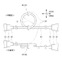
図6を参照して、本実施形態のインダクタ46(図2参照)として用いられるループ部60について説明する。本実施形態では、共振回路を形成するインダクタ46としてループ部60が用いられる。ループ部60は、電池回路モジュール40(図2参照)の入出力回路43と、電池モジュール30とを接続する配線61を、ループ状に形成した部位である。従って、共振回路を形成するために各種素子または機器(例えばリアクトル等)が用いられる場合に比べて、電源システム1の構成が簡素化される。ループ部60の形状を維持するために、ループ部60の少なくとも1つの箇所(本実施形態では2か所)には、配線を結束する結束バンド62が装着されている。なお、ループ部60のループの直径(本実施形態では内径)をDとする。
<Loop part>
A
電池モジュール30における電流を直流に近づけるために、共振回路におけるL×Cの値を大きくする際には、インダクタ46(ループ部60)のL値を厳密に設定する必要は無い。従って、簡易な構成のループ部60を採用しても、リンギングの影響は適切に抑制される。
When increasing the value of L×C in the resonance circuit in order to bring the current in the
入出力回路43には、配線61を繋ぐ第1端子45が設けられている。また、配線61には、第1端子45に着脱可能に装着される第1配線端子64が設けられている。従って、作業者は、入出力回路43の第1端子45と配線61の第1配線端子64の着脱を行うことで、入出力回路43に装着する電池モジュール30を適切に交換することができる。
The input/
電池モジュール30には、配線61を繋ぐ第2端子33が設けられている。また、配線61には、第2端子33に着脱可能に装着される第2配線端子65が設けられている。従って、作業者は、電池モジュール30の第2端子33と配線61の第2配線端子65の着脱を行うことで、入出力回路43に装着する電池モジュール30を適切に交換することができる。
The
なお、本実施形態の配線61には、第1配線端子64と第2配線端子65が共に設けられている。従って、作業者は、電池モジュール30を配線61と共に交換することも可能であり、配線61を入出力端子43に接続したまま電池モジュール30のみを交換することも可能である。従って、電池モジュール30を交換する際の自由度が高い。また、配線61を交換する必要がある場合(例えば、配線61が故障した場合、または、ループ部60の形状等が異なる配線61に交換する場合等)には、作業者は、配線61のみを交換することも容易である。ただし、配線61には、第1配線端子64と第2配線端子65の一方のみが設けられていてもよい。つまり、配線61の両端の一方が、入出力端子43または電池モジュール30に固定されていてもよい。
The
図7を参照して、ループ部60の有無、ループ部60の寸法、および形状と、L値の関係を確認するための評価試験の結果について説明する。本評価試験では、ループ部60の有無、寸法、および形状の少なくともいずれかが互いに異なる6つの評価対象(1)~(6)についてL値を取得した。(1)~(6)の配線は、いずれも同一の配線61によって形成されている。(1)の評価対象は、ループ部60が形成されていない配線61そのものである。(2)の評価対象は、直径Dが60mmである略真円状のループ部60を有する。(3)の評価対象のループ部60は、(2)のループ部60をA方向(図6参照)に10mm潰して略楕円形としたものである。(4)の評価対象のループ部60は、(2)のループ部60をB方向(図6参照)に10mm潰して略楕円形としたものである。(5)の評価対象は、直径Dが70mmである略真円状のループ部60を有する。(6)の評価対象は、直径Dが50mmである略真円状のループ部60を有する。なお、(2)~(5)のループ部60は、いずれも配線61を2回ループさせることで形成されている。
The results of an evaluation test for confirming the relationship between the presence or absence of the
図7に示すように、ループ部60を備える(2)~(6)の評価対象のL値は、ループ部60を有さない(1)の評価対象のL値に比べて大きい値となった。これより、ループ部60を形成することで大きなL値を確保できることが分かる。また、(2)~(4)を比較すると、ループ部60の円の形状(真円または楕円)、および楕円の方向がL値に与える影響が小さいことが分かる。従って、ループ部60の形状を厳密に規定しなくても、ループ部60を用いることでリンギングの影響が適切に抑えられると言える。また、(2)、(5)、および(6)を比較すると、ループ部60の直径Dを大きくする程、L値が大きくなることが分かる。従って、ループ部60の直径Dを調整することで、電流を直流に近づけるために必要なL値を確保してもよい。
As shown in FIG. 7, the L values of the evaluation objects (2) to (6) with the
以上、具体的な実施形態を挙げて本発明を詳細に説明したが、これらは例示にすぎず、請求の範囲を限定するものではない。請求の範囲に記載の技術には、以上に記載した実施形態を様々に変形、変更したものが含まれる。 Although the present invention has been described in detail with reference to specific embodiments, these are merely examples and do not limit the scope of the claims. The technology described in the claims includes various modifications and changes of the embodiments described above.
1 電源システム
7 メインライン
10 ストリング
20 スイープモジュール
30 電池モジュール
31 電池
33 第2端子
40 電力回路モジュール
41 第1スイッチング素子
42 第2スイッチング素子
43 入出力回路
45 第1端子
46 インダクタ
47 コンデンサ
60 ループ部
61 配線
64 第1配線端子
65 第2配線端子
1
Claims (1)
前記メインラインに接続された複数のスイープモジュールと、
を有し、
前記スイープモジュールは、
少なくとも1つの電池を含む電池モジュールと、
前記電池モジュールを前記メインラインに接続するように構成された入出力回路と、
当該入出力回路に配置され、前記電池モジュールと前記メインラインとの接続および切断を切り替える、少なくとも1つのスイッチング素子と、
前記入出力回路に、前記電池モジュールと並列に取り付けられたコンデンサと、
前記入出力回路と前記電池モジュールを接続する配線と、
を有し、
前記複数のスイープモジュールは、前記スイッチング素子のオンとオフの交互駆動を制御するゲート信号を、定められた遅延時間毎に順に各々の前記入出力回路に出力することで、前記メインラインに接続する前記電池モジュールを順次切り替えるスイープ制御を実行するように構成されており、
前記配線は、ループが形成された状態で維持されており、
前記入出力回路は、前記配線を繋ぐ第1端子を有し、且つ、前記電池モジュールは、前記配線を繋ぐ第2端子を有しており、
前記配線は、前記第1端子に着脱可能に装着される第1配線端子、および、前記第2端子に着脱可能に装着される第2配線端子を有しており、
前記第1端子と前記第1配線端子の着脱を行うことによって前記入出力回路に接続する前記電池モジュールを前記ループが形成された配線と共に交換可能となり、且つ、前記第2端子と前記第2配線端子の着脱を行うことによって前記入出力回路に接続する前記電池モジュールを前記ループが形成された配線から離して交換可能となるように構成されている、
電源システム。 main line and
a plurality of sweep modules connected to the mainline;
has
The sweep module is
a battery module including at least one battery;
an input/output circuit configured to connect the battery module to the main line;
at least one switching element arranged in the input/output circuit for switching connection and disconnection between the battery module and the main line;
a capacitor attached to the input/output circuit in parallel with the battery module;
wiring that connects the input/output circuit and the battery module;
has
The plurality of sweep modules are connected to the main line by sequentially outputting gate signals for controlling alternate driving of the switching elements between on and off to each of the input/output circuits at predetermined delay times. configured to execute sweep control for sequentially switching the battery modules,
The wiring is maintained in a looped state,
The input/output circuit has a first terminal that connects the wiring, and the battery module has a second terminal that connects the wiring,
The wiring has a first wiring terminal detachably attached to the first terminal and a second wiring terminal detachably attached to the second terminal,
By attaching and detaching the first terminal and the first wiring terminal, the battery module connected to the input/output circuit can be replaced together with the wiring in which the loop is formed, and the second terminal and the second wiring can be replaced. The battery module connected to the input/output circuit can be separated from the looped wiring and replaced by attaching and detaching the terminal.
power system.
Priority Applications (3)
| Application Number | Priority Date | Filing Date | Title |
|---|---|---|---|
| JP2018222765A JP7121908B2 (en) | 2018-11-28 | 2018-11-28 | power system |
| US16/680,870 US11196252B2 (en) | 2018-11-28 | 2019-11-12 | Power supply system |
| CN201911099158.8A CN111245037B (en) | 2018-11-28 | 2019-11-12 | Power Systems |
Applications Claiming Priority (1)
| Application Number | Priority Date | Filing Date | Title |
|---|---|---|---|
| JP2018222765A JP7121908B2 (en) | 2018-11-28 | 2018-11-28 | power system |
Publications (2)
| Publication Number | Publication Date |
|---|---|
| JP2020089140A JP2020089140A (en) | 2020-06-04 |
| JP7121908B2 true JP7121908B2 (en) | 2022-08-19 |
Family
ID=70770470
Family Applications (1)
| Application Number | Title | Priority Date | Filing Date |
|---|---|---|---|
| JP2018222765A Active JP7121908B2 (en) | 2018-11-28 | 2018-11-28 | power system |
Country Status (3)
| Country | Link |
|---|---|
| US (1) | US11196252B2 (en) |
| JP (1) | JP7121908B2 (en) |
| CN (1) | CN111245037B (en) |
Families Citing this family (5)
| Publication number | Priority date | Publication date | Assignee | Title |
|---|---|---|---|---|
| JP6960897B2 (en) | 2018-10-31 | 2021-11-05 | 株式会社豊田中央研究所 | Power supply |
| JP6898904B2 (en) | 2018-10-31 | 2021-07-07 | 株式会社豊田中央研究所 | Power supply |
| JP6960898B2 (en) * | 2018-10-31 | 2021-11-05 | 株式会社豊田中央研究所 | Power supply |
| JP7089673B2 (en) * | 2018-11-29 | 2022-06-23 | トヨタ自動車株式会社 | Power system |
| US11837905B2 (en) * | 2021-05-25 | 2023-12-05 | Cyberswitchingpatents, Llc | Battery charger system |
Citations (1)
| Publication number | Priority date | Publication date | Assignee | Title |
|---|---|---|---|---|
| JP2018182782A (en) | 2017-04-03 | 2018-11-15 | 株式会社豊田中央研究所 | Power supply device |
Family Cites Families (17)
| Publication number | Priority date | Publication date | Assignee | Title |
|---|---|---|---|---|
| JP4605952B2 (en) * | 2001-08-29 | 2011-01-05 | 株式会社日立製作所 | Power storage device and control method thereof |
| JP2004336836A (en) * | 2003-04-30 | 2004-11-25 | Honda Motor Co Ltd | Motor drive |
| US7446433B2 (en) * | 2004-01-23 | 2008-11-04 | American Power Conversion Corporation | Methods and apparatus for providing uninterruptible power |
| JP4101205B2 (en) * | 2004-05-11 | 2008-06-18 | 松下電器産業株式会社 | Battery pack and power supply |
| JP5486780B2 (en) * | 2008-07-01 | 2014-05-07 | 株式会社日立製作所 | Battery system |
| JP5417898B2 (en) * | 2009-02-27 | 2014-02-19 | Tdk株式会社 | Switching power supply |
| DE102010027864A1 (en) * | 2010-04-16 | 2011-12-15 | Sb Limotive Company Ltd. | Battery with variable output voltage |
| JP2012209902A (en) * | 2011-03-30 | 2012-10-25 | Semiconductor Components Industries Llc | Input and output circuit |
| KR101383167B1 (en) * | 2011-10-20 | 2014-04-10 | 주식회사 엘지화학 | Battery Pack of Improved Safety |
| US9496749B2 (en) * | 2012-03-23 | 2016-11-15 | Hitachi Automotive Systems, Ltd. | Storage battery control device and electrical storage device |
| JP5982632B2 (en) * | 2012-03-30 | 2016-08-31 | パナソニックIpマネジメント株式会社 | In-vehicle power supply circuit and in-vehicle power supply unit using the same |
| JPWO2014132321A1 (en) * | 2013-02-26 | 2017-02-02 | 株式会社日立製作所 | Power supply |
| WO2016081473A1 (en) * | 2014-11-17 | 2016-05-26 | Shibashis Bhowmik | Converter with phase-offset switching |
| JP6531745B2 (en) | 2016-10-27 | 2019-06-19 | 株式会社豊田中央研究所 | POWER SUPPLY DEVICE AND CONTROL METHOD OF POWER SUPPLY DEVICE |
| US9784244B1 (en) * | 2017-03-29 | 2017-10-10 | Tarek O. Souryal | Energy collection pod |
| JP6805933B2 (en) * | 2017-03-31 | 2020-12-23 | 株式会社豊田中央研究所 | Power supply |
| JP7100804B2 (en) * | 2018-11-28 | 2022-07-14 | トヨタ自動車株式会社 | Power system |
-
2018
- 2018-11-28 JP JP2018222765A patent/JP7121908B2/en active Active
-
2019
- 2019-11-12 CN CN201911099158.8A patent/CN111245037B/en active Active
- 2019-11-12 US US16/680,870 patent/US11196252B2/en active Active
Patent Citations (1)
| Publication number | Priority date | Publication date | Assignee | Title |
|---|---|---|---|---|
| JP2018182782A (en) | 2017-04-03 | 2018-11-15 | 株式会社豊田中央研究所 | Power supply device |
Also Published As
| Publication number | Publication date |
|---|---|
| US11196252B2 (en) | 2021-12-07 |
| CN111245037B (en) | 2023-08-08 |
| US20200169081A1 (en) | 2020-05-28 |
| CN111245037A (en) | 2020-06-05 |
| JP2020089140A (en) | 2020-06-04 |
Similar Documents
| Publication | Publication Date | Title |
|---|---|---|
| JP7121908B2 (en) | power system | |
| JP7129008B2 (en) | power system | |
| JP7100804B2 (en) | Power system | |
| JP7145391B2 (en) | power system | |
| JP7025716B2 (en) | Power system | |
| EP3661005B1 (en) | Power supply system | |
| JP7216889B2 (en) | power system | |
| JP7089673B2 (en) | Power system | |
| JP7145392B2 (en) | power system | |
| JP7054453B2 (en) | Power system | |
| JP2021168556A (en) | Power system | |
| JP2021151056A (en) | Power supply system |
Legal Events
| Date | Code | Title | Description |
|---|---|---|---|
| A621 | Written request for application examination |
Free format text: JAPANESE INTERMEDIATE CODE: A621 Effective date: 20210325 |
|
| A131 | Notification of reasons for refusal |
Free format text: JAPANESE INTERMEDIATE CODE: A131 Effective date: 20220106 |
|
| A521 | Request for written amendment filed |
Free format text: JAPANESE INTERMEDIATE CODE: A523 Effective date: 20220307 |
|
| TRDD | Decision of grant or rejection written | ||
| A01 | Written decision to grant a patent or to grant a registration (utility model) |
Free format text: JAPANESE INTERMEDIATE CODE: A01 Effective date: 20220707 |
|
| A61 | First payment of annual fees (during grant procedure) |
Free format text: JAPANESE INTERMEDIATE CODE: A61 Effective date: 20220720 |
|
| R151 | Written notification of patent or utility model registration |
Ref document number: 7121908 Country of ref document: JP Free format text: JAPANESE INTERMEDIATE CODE: R151 |