JP7115398B2 - Respiratory support device for mobile - Google Patents

Respiratory support device for mobile Download PDF

Info

Publication number
JP7115398B2
JP7115398B2 JP2019073594A JP2019073594A JP7115398B2 JP 7115398 B2 JP7115398 B2 JP 7115398B2 JP 2019073594 A JP2019073594 A JP 2019073594A JP 2019073594 A JP2019073594 A JP 2019073594A JP 7115398 B2 JP7115398 B2 JP 7115398B2
Authority
JP
Japan
Prior art keywords
compression
backrest
unit
bag
driver
Prior art date
Legal status (The legal status is an assumption and is not a legal conclusion. Google has not performed a legal analysis and makes no representation as to the accuracy of the status listed.)
Active
Application number
JP2019073594A
Other languages
Japanese (ja)
Other versions
JP2020172127A5 (en
JP2020172127A (en
Inventor
拓也 武田
貴博 内藤
Current Assignee (The listed assignees may be inaccurate. Google has not performed a legal analysis and makes no representation or warranty as to the accuracy of the list.)
Denso Corp
Original Assignee
Denso Corp
Priority date (The priority date is an assumption and is not a legal conclusion. Google has not performed a legal analysis and makes no representation as to the accuracy of the date listed.)
Filing date
Publication date
Application filed by Denso Corp filed Critical Denso Corp
Priority to JP2019073594A priority Critical patent/JP7115398B2/en
Publication of JP2020172127A publication Critical patent/JP2020172127A/en
Publication of JP2020172127A5 publication Critical patent/JP2020172127A5/ja
Application granted granted Critical
Publication of JP7115398B2 publication Critical patent/JP7115398B2/en
Active legal-status Critical Current
Anticipated expiration legal-status Critical

Links

Images

Landscapes

  • Seats For Vehicles (AREA)

Description

本開示は、移動体用呼吸支援装置に関するものである。 The present disclosure relates to a respiratory support device for a mobile body.

特許文献1には、車両のシートの背もたれ部の傾斜角度と、背もたれ部のうちのユーザの胸椎と腰椎との境界部近傍に対応する部分のユーザ方向への突出量とを変化させることで、ユーザが呼吸を行い易い姿勢に変化させる技術が開示されている。 In Patent Document 1, by changing the inclination angle of the backrest portion of the vehicle seat and the amount of protrusion in the user direction of the portion of the backrest portion corresponding to the vicinity of the boundary between the user's thoracic vertebrae and the lumbar vertebrae, Techniques have been disclosed for changing the posture to a posture that allows the user to breathe easily.

特開2015-97611号公報JP 2015-97611 A

しかしながら、特許文献1に開示の技術では、シートの背もたれ部の傾斜角度を変化させる等、ユーザの姿勢を前後に傾けさせるため、運転姿勢から逸脱した姿勢となり易い。よって、ユーザの視線が大きく変動しやすく、ユーザがドライバの場合には車両の走行中に実施することが困難である。 However, in the technique disclosed in Patent Document 1, the user's posture is tilted back and forth by, for example, changing the tilt angle of the backrest portion of the seat. Therefore, the user's line of sight tends to fluctuate greatly, and if the user is a driver, it is difficult to perform this while the vehicle is running.

この開示のひとつの目的は、移動体の移動中に移動体の操作者の呼吸を支援する場合であっても、この操作者による移動体の移動操作を妨げにくくすることを可能にする移動体用呼吸支援装置を提供することにある。 One object of the present disclosure is to provide a mobile body that makes it difficult for the operator to move the mobile body even when the breathing of the operator of the mobile body is supported during movement of the mobile body. To provide a respiratory support device for

上記目的は独立請求項に記載の特徴の組み合わせにより達成され、また、下位請求項は、開示の更なる有利な具体例を規定する。特許請求の範囲に記載した括弧内の符号は、ひとつの態様として後述する実施形態に記載の具体的手段との対応関係を示すものであって、本開示の技術的範囲を限定するものではない。 The above objects are achieved by the combination of features stated in the independent claims, and the subclaims define further advantageous embodiments of the disclosure. The symbols in parentheses described in the claims indicate the corresponding relationship with specific means described in the embodiments described later as one aspect, and do not limit the technical scope of the present disclosure. .

上記目的を達成するために、本開示の移動体用呼吸支援装置は、移動体で用いられ、移動体の乗員が着座するシート(Se)の背もたれ部(SB)の両側に設けられて背もたれ部よりも前方に突出した突出部であるサイドサポート(SSR,SSL)にそれぞれ設けられて、背もたれ部の幅方向の内側に向けて圧迫可能な圧迫部(24,24a)と、圧迫部の動作を制御する圧迫制御部(217,217a)とを備え、圧迫制御部での制御によって圧迫部で背もたれ部の幅方向の内側に向けて圧迫を行わせることで、シートに着座する乗員の胸郭を背もたれ部の幅方向の内側に向けて圧迫する一方、圧迫制御部での制御によって圧迫部での圧迫を終了させることで、シートに着座する乗員の胸郭を圧迫から開放する。 In order to achieve the above object, the breathing support device for a mobile body of the present disclosure is used in a mobile body, and is provided on both sides of a backrest part (SB) of a seat (Se) on which an occupant of the mobile body sits. Compressing parts (24, 24a) provided on the side supports (SSR, SSL), which are protruding parts that protrude forward from the backrest, that can compress inward in the width direction of the backrest, and control the operation of the compressing parts and a compression control unit (217, 217a) for pressing the thorax of the occupant seated on the seat toward the inside of the backrest portion in the width direction under the control of the compression control unit. The chest of the occupant seated on the seat is released from the compression by terminating the compression in the compression section under the control of the compression control section.

これによれば、圧迫部は、移動体の乗員が着座するシートの背もたれ部の両側に設けられて背もたれ部よりも前方に突出した突出部であるサイドサポートにそれぞれ設けられて、背もたれ部の幅方向の内側に向けて圧迫可能である。よって、圧迫部で圧迫を行うと、シートに着座する乗員を背もたれ部の幅方向の内側に向けて圧迫することになる。この場合、乗員の胸郭を側方から圧迫することになる。乗員の胸郭を側方から圧迫すると、胸郭の幅方向の縮小運動を促すことで、呼気運動を支援することができる。圧迫制御部では、圧迫部での圧迫と圧迫の終了とを制御するので、呼気運動を支援する期間を調整することで、乗員の呼気期間を調整するといった呼吸の支援が可能になる。また、乗員の胸郭を側方から圧迫して胸郭の幅方向の縮小運動を促したとしても、乗員の姿勢は前後に傾きにくい。よって、乗員が移動体の操作者であった場合でも、圧迫部での圧迫によってこの操作者が移動体の移動操作を行う姿勢から逸脱した姿勢となりにくい。その結果、移動体の移動操作中に移動体の操作者の呼吸を支援する場合であっても、この操作者による移動操作を妨げにくくすることが可能になる。 According to this, the compression portions are provided on both sides of the backrest portion of the seat on which the occupant of the moving body sits, and are provided on the side supports, which are projecting portions that project forward from the backrest portion. can be compressed toward the inside of the Therefore, when the pressure is applied by the pressure portion, the occupant seated on the seat is pressed inward in the width direction of the backrest portion. In this case, the chest of the occupant is pressed from the side. When the occupant's ribcage is compressed from the side, it is possible to assist the expiratory movement by promoting contraction of the ribcage in the width direction. Since the compression control section controls the compression and the end of compression in the compression section, it is possible to support breathing such as adjusting the expiration period of the occupant by adjusting the period during which the expiratory movement is supported. In addition, even if the chest of the occupant is pressed from the side to encourage contraction of the thorax in the width direction, the occupant's posture is unlikely to tilt forward or backward. Therefore, even if the occupant is the operator of the moving body, the operator is unlikely to deviate from the posture of performing the moving operation of the moving body due to the compression by the pressing section. As a result, even when the breathing of the operator of the mobile object is assisted during the operation of moving the mobile object, it is possible to make it difficult for the operator to interfere with the operation of moving the mobile object.

支援システム1の概略的な構成の一例を示す図である。1 is a diagram showing an example of a schematic configuration of a support system 1; FIG. シートSeにおける圧迫装置24の内蔵位置の一例について説明を行うための斜視図である。FIG. 3 is a perspective view for explaining an example of a built-in position of a compression device 24 in a seat Se; 実施形態1におけるシートSeの前方から見た圧迫装置24の配置の一例について説明を行うための図である。4 is a diagram for explaining an example of the arrangement of the compression device 24 viewed from the front of the seat Se in the first embodiment; FIG. 実施形態1におけるシートSeの右側方から見た圧迫装置24の配置の一例について説明を行うための図である。4 is a diagram for explaining an example of the arrangement of the compression device 24 viewed from the right side of the seat Se in Embodiment 1. FIG. HCU21の概略的な構成の一例を示す図である。It is a figure which shows an example of a schematic structure of HCU21. 実施形態1における圧迫装置24の各袋体区画の膨張の態様について説明するための図である。FIG. 4 is a diagram for explaining how each bag compartment of the compression device 24 in Embodiment 1 is inflated. HCU21での呼吸支援関連処理の流れの一例を示すフローチャートである。It is a flow chart which shows an example of a flow of respiratory support related processing in HCU21. 実施形態2におけるシートSeの前方から見た圧迫装置24の配置の一例について説明を行うための図である。FIG. 11 is a diagram for explaining an example of the arrangement of the compression device 24 viewed from the front of the seat Se in Embodiment 2; 実施形態2における圧迫装置24の各袋体区画の膨張の態様について説明するための図である。FIG. 11 is a diagram for explaining the mode of inflation of each bag section of the compression device 24 in Embodiment 2; 支援システム1aの概略的な構成の一例を示す図である。It is a figure which shows an example of a schematic structure of the support system 1a. 実施形態5におけるシートSeの前方から見た圧迫装置24aの配置の一例について説明を行うための図である。FIG. 21 is a diagram for explaining an example of the arrangement of the compression device 24a viewed from the front of the seat Se in Embodiment 5; 実施形態5におけるシートSeの上方から見た圧迫装置24aの形状の一例について説明を行うための図である。FIG. 14 is a diagram for explaining an example of the shape of the compression device 24a viewed from above the seat Se in Embodiment 5; HCU21aの概略的な構成の一例を示す図である。It is a figure which shows an example of a schematic structure of HCU21a. 実施形態5における圧迫装置24aでの圧迫の態様について説明するための図である。FIG. 11 is a diagram for explaining a mode of compression by a compression device 24a according to Embodiment 5; 実施形態6における圧迫装置24aでの圧迫の態様について説明するための図である。FIG. 14 is a diagram for explaining the mode of compression by the compression device 24a in Embodiment 6; 実施形態6におけるシートSeの上方から見た圧迫装置24aの形状の一例について説明を行うための図である。FIG. 21 is a diagram for explaining an example of the shape of the compression device 24a viewed from above the seat Se in Embodiment 6; 実施形態7におけるシートSeの右側方から見た圧迫装置24aの配置の一例について説明を行うための図である。FIG. 21 is a diagram for explaining an example of the arrangement of the compression device 24a viewed from the right side of the seat Se in Embodiment 7;

図面を参照しながら、開示のための複数の実施形態を説明する。なお、説明の便宜上、複数の実施形態の間において、それまでの説明に用いた図に示した部分と同一の機能を有する部分については、同一の符号を付し、その説明を省略する場合がある。同一の符号を付した部分については、他の実施形態における説明を参照することができる。 A number of embodiments for the disclosure are described with reference to the drawings. For convenience of explanation, in some embodiments, parts having the same functions as the parts shown in the drawings used in the explanation so far are denoted by the same reference numerals, and the explanation thereof may be omitted. be. The descriptions in the other embodiments can be referred to for the parts with the same reference numerals.

(実施形態1)
<支援システム1の概略構成>
以下、実施形態1について図面を用いて説明する。図1に示す支援システム1は、自動車(以下、単に車両)で用いられるものであり、HMI(Human Machine Interface)システム2、ロケータ3、ナビゲーション装置4、周辺監視センサ5、運転支援ECU6、及び車両状態センサ7を含んでいる。HMIシステム2、ロケータ3、ナビゲーション装置4、運転支援ECU6、及び車両状態センサ7は、例えば車内LANに接続されているものとする。支援システム1を搭載している車両を以降では自車と呼ぶ。
(Embodiment 1)
<Schematic configuration of support system 1>
Embodiment 1 will be described below with reference to the drawings. The assistance system 1 shown in FIG. 1 is used in an automobile (hereinafter simply referred to as a vehicle), and includes an HMI (Human Machine Interface) system 2, a locator 3, a navigation device 4, a peripheral monitoring sensor 5, a driving assistance ECU 6, and the vehicle. A state sensor 7 is included. The HMI system 2, the locator 3, the navigation device 4, the driving support ECU 6, and the vehicle state sensor 7 are assumed to be connected to, for example, an in-vehicle LAN. A vehicle equipped with the support system 1 is hereinafter referred to as the own vehicle.

ロケータ3は、GNSS(Global Navigation Satellite System)受信機及び慣性センサを備えている。GNSS受信機は、複数の人工衛星からの測位信号を受信する。慣性センサは、例えばジャイロセンサ及び加速度センサを備える。ロケータ3は、GNSS受信機で受信する測位信号と、慣性センサの計測結果とを組み合わせることにより、自車の車両位置を逐次測位する。なお、車両位置の測位には、自車に搭載された車速センサから逐次出力される信号から求めた走行距離を用いる構成としてもよい。 The locator 3 has a GNSS (Global Navigation Satellite System) receiver and an inertial sensor. A GNSS receiver receives positioning signals from multiple satellites. Inertial sensors include, for example, gyro sensors and acceleration sensors. The locator 3 sequentially locates the vehicle position of the own vehicle by combining the positioning signals received by the GNSS receiver and the measurement results of the inertial sensor. It should be noted that the positioning of the vehicle position may be performed using the travel distance obtained from the signals sequentially output from the vehicle speed sensor mounted on the own vehicle.

ナビゲーション装置4は、地図データを格納した地図データベース(以下、地図DB)41を備え、設定される目的地までの時間優先,距離優先等の条件を満たす経路を探索し、その探索した経路に従った経路案内を行う。地図DB41は、例えば不揮発性メモリであって、リンクデータ,ノードデータ,道路属性等の地図データを格納している。 The navigation device 4 includes a map database (hereinafter referred to as a map DB) 41 storing map data, searches for a route to a set destination that satisfies conditions such as time priority and distance priority, and follows the searched route. route guidance. The map DB 41 is, for example, a non-volatile memory, and stores map data such as link data, node data, and road attributes.

リンクデータは、リンクを特定する固有番号、リンクの長さを示すリンク長、リンク方向、リンクの形状情報、リンクの始端と終端とのノード座標、及び道路属性の各データから構成される。道路属性としては、道路名称、道路種別、道路幅員、車線数、及び速度規制値等がある。一方、ノードデータは、地図上のノード毎に固有の番号を付したノードID、ノード座標、ノード名称、ノード種別、ノードに接続するリンクのリンクIDが記述される接続リンクID、交差点種別等の各データから構成される。なお、地図データは、通信モジュールを用いて自車の外部から取得する構成としてもよい。また、地図DB41は、自車の走行履歴データも格納する構成とすればよい。例えば、リンク別に、自車の走行回数を走行履歴データとして格納する構成とすればよい。また、自車を利用するユーザが複数存在する場合には、ユーザごとの電子キーの識別情報を、電子キーを用いた車両の認証時に取得することで、ユーザ別に走行履歴データを格納することが好ましい。 The link data consists of a unique number specifying a link, a link length indicating the length of the link, a link direction, link shape information, node coordinates of the start and end of the link, and road attribute data. Road attributes include road name, road type, road width, number of lanes, and speed limit value. On the other hand, the node data includes a node ID with a unique number assigned to each node on the map, node coordinates, node name, node type, connection link ID describing the link ID of the link connecting to the node, intersection type, and the like. It consists of each data. Note that the map data may be acquired from outside the own vehicle using a communication module. Further, the map DB 41 may be configured to store travel history data of the own vehicle. For example, the number of times the host vehicle has traveled may be stored as travel history data for each link. In addition, when there are multiple users who use the vehicle, it is possible to store driving history data for each user by acquiring the identification information of the electronic key for each user when authenticating the vehicle using the electronic key. preferable.

周辺監視センサ5は、歩行者,他車等の移動物体、及び路上の落下物等の静止物体といった自車周辺の障害物を検出する。他にも、自車周辺の走行区画線等の路面標示等を検出する。周辺監視センサ5は、例えば、自車周囲の所定範囲を撮像する周辺監視カメラ、自車周囲の所定範囲に探査波を送信するミリ波レーダ、ソナー、LIDAR(Light Detection and Ranging/Laser Imaging Detection and Ranging)等のセンサである。周辺監視カメラは、逐次撮像する撮像画像をセンシング情報として運転支援ECU6へ逐次出力する。ソナー、ミリ波レーダ、LIDAR等の探査波を送信するセンサは、障害物によって反射された反射波を受信した場合に得られる受信信号に基づく走査結果をセンシング情報として運転支援ECU6へ逐次出力する。 The surroundings monitoring sensor 5 detects obstacles around the vehicle, such as moving objects such as pedestrians and other vehicles, and stationary objects such as falling objects on the road. In addition, road markings such as lane markings around the vehicle are detected. The surroundings monitoring sensor 5 includes, for example, a surroundings monitoring camera that images a predetermined range around the vehicle, a millimeter wave radar that transmits search waves to a predetermined range around the vehicle, a sonar, a LIDAR (Light Detection and Ranging/Laser Imaging Detection and Ranging) and other sensors. The periphery monitoring camera sequentially outputs captured images to the driving support ECU 6 as sensing information. Sensors that transmit search waves such as sonar, millimeter wave radar, and LIDAR sequentially output scanning results based on received signals obtained when reflected waves reflected by obstacles are received to the driving support ECU 6 as sensing information.

運転支援ECU6は、自車の運転支援を行う電子制御装置である。運転支援ECU6は、ロケータ3から取得した自車の車両位置,地図DB41から取得した地図データ,周辺監視センサ5から取得したセンシング情報等から、自車の周辺環境を認識する。一例として、周辺監視センサ5から取得したセンシング情報から、自車の周囲の物体の形状及び移動状態を認識し、自車の車両位置及び地図データと組み合わせることで、実際の走行環境を三次元で再現した仮想空間を生成すればよい。また、運転支援ECU6は、認識した周辺環境をもとに、車両を制御する電子制御装置との連携によって自車の加減速制御及び/又は操舵制御を行うことにより、自車の運転支援を行ってもよい。運転支援の一例としては、障害物回避のために自動減速する支援等がある。 The driving support ECU 6 is an electronic control unit that supports driving of the own vehicle. The driving support ECU 6 recognizes the surrounding environment of the own vehicle from the vehicle position of the own vehicle obtained from the locator 3, the map data obtained from the map DB 41, the sensing information obtained from the surrounding monitoring sensor 5, and the like. As an example, by recognizing the shape and movement state of objects around the vehicle from the sensing information acquired from the surroundings monitoring sensor 5, and combining it with the vehicle position and map data, the actual driving environment can be visualized in three dimensions. It is sufficient to generate a reproduced virtual space. In addition, the driving support ECU 6 performs acceleration/deceleration control and/or steering control of the own vehicle in cooperation with an electronic control device that controls the vehicle based on the recognized surrounding environment, thereby supporting the driving of the own vehicle. may An example of driving assistance is automatic deceleration assistance for avoiding obstacles.

車両状態センサ7は、自車の走行状態,操作状態等の自車の状態を検出するためのセンサ群である。車両状態センサ7としては、自車の車速を検出する車速センサ,自車のステアリングの操舵角を検出する舵角センサ,自車の加減速度を検出する加速度センサ,シフトポジションを検出するシフトポジションセンサ,自車でのブレーキ操作を検出するブレーキスイッチ等がある。車両状態センサ7は、検出結果を車内LANへ出力する。なお、車両状態センサ7での検出結果は、自車に搭載されるECUを介して車内LANへ出力される構成であってもよい。 The vehicle state sensor 7 is a group of sensors for detecting the state of the own vehicle such as the running state of the own vehicle and the operation state of the own vehicle. The vehicle state sensors 7 include a vehicle speed sensor for detecting the vehicle speed of the vehicle, a steering angle sensor for detecting the steering angle of the steering of the vehicle, an acceleration sensor for detecting the acceleration and deceleration of the vehicle, and a shift position sensor for detecting the shift position. , and a brake switch for detecting the braking operation of the own vehicle. The vehicle state sensor 7 outputs the detection result to the in-vehicle LAN. The detection result of the vehicle state sensor 7 may be output to the in-vehicle LAN via an ECU mounted on the own vehicle.

HMIシステム2は、HCU(Human Machine Interface Control Unit)21、生体センサ22、操作デバイス23、圧迫装置24、供給装置25、及び圧力センサ26を含んでいる。HMIシステム2は、自車のドライバからの入力操作を受け付けたり、ドライバの状態を監視したり、ドライバの呼吸運動を支援したりする。HCU21、圧迫装置24、供給装置25、及び圧力センサ26を含む構成が、呼吸支援装置20にあたる。呼吸支援装置20は、ドライバの呼吸運動を支援する。この呼吸支援装置20が移動体用呼吸支援装置に相当する。 The HMI system 2 includes an HCU (Human Machine Interface Control Unit) 21 , a biosensor 22 , an operation device 23 , a compression device 24 , a supply device 25 and a pressure sensor 26 . The HMI system 2 receives input operations from the driver of the vehicle, monitors the driver's condition, and assists the driver's breathing exercise. A configuration including the HCU 21 , the compression device 24 , the supply device 25 and the pressure sensor 26 corresponds to the respiratory support device 20 . The respiratory assistance device 20 assists the driver's breathing exercise. This respiratory support device 20 corresponds to a mobile respiratory support device.

生体センサ22は、自車のドライバの生体情報を計測し、計測した生体情報をHCU21へ逐次出力する。生体センサ22は、ステアリングホイール,運転席シート等に設けるといったように自車に設ける構成としてもよいし、ドライバが装着するウェアラブルデバイスに設けられる構成としてもよい。ドライバが装着するウェアラブルデバイスに生体センサ22が設けられている場合には、例えば近距離無線通信を介して、生体センサ22での計測結果をHCU21が取得する構成とすればよい。生体センサ22で計測する生体情報の一例としては、呼吸,脈拍,心拍等が挙げられる。 The biosensor 22 measures the biometric information of the driver of the vehicle, and sequentially outputs the measured biometric information to the HCU 21 . The biosensor 22 may be provided in the vehicle such as in the steering wheel, the driver's seat, etc., or may be provided in a wearable device worn by the driver. If the wearable device worn by the driver is provided with the biosensor 22, the HCU 21 may acquire the measurement result of the biosensor 22 via short-range wireless communication, for example. Examples of biological information measured by the biological sensor 22 include respiration, pulse, and heartbeat.

生体センサ22としては、測定で得られる脈波の波形から心拍数又は脈拍数を計測する光電式脈波センサ,インピーダンス式脈波センサ等の脈波センサが挙げられる。他にも、GHz帯のマイクロ波を用いたドップラーセンサによって非接触に呼吸の動きを検知する呼吸センサが挙げられる。呼吸センサとしては、シートベルト,シートバックに設けられる圧力センサを用いる構成としてもよい。これらの圧力センサを呼吸センサとして用いる場合には、圧力が上昇するタイミングを吸気のタイミングと検出する一方、圧力が下降するタイミングを呼気のタイミングと検出すればよい。また、呼吸センサとしては、ドライバの顔を撮像するカメラを用いる構成としてもよい。カメラを呼吸センサとして用いる場合には、上体の呼吸に伴う体動(肩,胸等)から呼吸の動きを検知する等すればよい。さらには、脈波から呼吸を推定する場合は、脈波センサを呼吸センサとして用いてもよい。 Examples of the biosensor 22 include a pulse wave sensor such as a photoelectric pulse wave sensor and an impedance pulse wave sensor that measure the heart rate or pulse rate from the pulse wave waveform obtained by measurement. Another example is a respiration sensor that detects respiration movement in a non-contact manner using a Doppler sensor that uses GHz-band microwaves. As the breathing sensor, a configuration using a seat belt or a pressure sensor provided on the seat back may be used. When these pressure sensors are used as respiration sensors, the timing at which the pressure rises is detected as the timing of inspiration, and the timing at which the pressure drops is detected as the timing of expiration. Moreover, as a respiration sensor, it is good also as a structure using the camera which images a driver's face. When a camera is used as a respiration sensor, respiration movement may be detected from body movements (shoulders, chest, etc.) associated with respiration of the upper body. Furthermore, when estimating respiration from a pulse wave, a pulse wave sensor may be used as a respiration sensor.

なお、生体センサ22は、ここに挙げたものに限らず、他のものを用いる構成としてもよい。また、生体センサ22として、呼吸,脈拍,心拍以外の生体情報を計測するものを用いる構成としてもよい。例えば、脳波,心拍ゆらぎ,発汗,体温,血圧,皮膚コンダクタンスを計測するものが挙げられる。 In addition, the biosensor 22 is not limited to those listed here, and may be configured to use other sensors. Also, the biosensor 22 may be configured to measure biometric information other than respiration, pulse, and heartbeat. For example, those that measure electroencephalograms, heartbeat fluctuations, perspiration, body temperature, blood pressure, and skin conductance can be mentioned.

操作デバイス23は、運転手が操作するスイッチ群である。例えば、操作デバイス23としては、自車のステアリングのスポーク部に設けられたステアリングスイッチ,ディスプレイを有する表示装置と一体となったタッチスイッチ等がある。 The operating device 23 is a group of switches operated by the driver. For example, the operation device 23 includes a steering switch provided on the spoke portion of the steering wheel of the vehicle, a touch switch integrated with a display device having a display, and the like.

圧迫装置24は、自車のシートSeに設けられる。圧迫装置24は、自車のシートSeに着座する乗員の胸郭を側方から圧迫する。圧迫装置24は、乗員の胸郭を側方から圧迫することで、乗員の呼吸運動を支援するための装置である。この圧迫装置24が圧迫部に相当する。本実施形態では、圧迫装置24は、ドライバが着座する運転席シートに設けられるものとして、以降の説明を行う。 The compression device 24 is provided on the seat Se of the vehicle. The compressing device 24 compresses the chest of the occupant seated on the seat Se of the vehicle from the side. The compression device 24 is a device for supporting the occupant's breathing exercise by compressing the occupant's chest from the side. This compression device 24 corresponds to the compression section. In the present embodiment, the compression device 24 is assumed to be provided in the driver's seat on which the driver sits.

圧迫装置24は、袋体である。袋体としての圧迫装置24は、供給装置25からの気体の注入によって膨張する。圧迫装置24は、この膨張によって、シートSeに着座するドライバの胸郭を側方から圧迫する。気体としては、例えば空気を用いる構成とすればよい。以下では、気体として空気を用いる場合を例に挙げて説明を行う。圧迫装置24は、注入された圧縮空気を、排気弁等によって排気することで収縮する構成とすればよい。以下では、排気に排気弁を用いる場合を例に挙げて説明を行う。また、圧迫装置24は、袋体がシートSeの背もたれ部の上下方向に複数の区画(以下、袋体区画)に分かれているものとする。なお、圧迫装置24の設け方の詳細については後述する。 The compression device 24 is a bag. The compression device 24 as a bag is inflated by injection of gas from the supply device 25 . Due to this expansion, the compression device 24 laterally compresses the chest of the driver seated on the seat Se. As the gas, for example, air may be used. Below, the case where air is used as gas is mentioned as an example, and it demonstrates. The compression device 24 may be configured to contract by exhausting the injected compressed air with an exhaust valve or the like. Below, the case where an exhaust valve is used for exhaust will be described as an example. In the compression device 24, the bag body is divided into a plurality of sections (hereinafter referred to as bag section) in the vertical direction of the backrest portion of the seat Se. The details of how to provide the compression device 24 will be described later.

供給装置25は、HCU21の指示に従って、圧迫装置24に空気を注入する。また、供給装置25は、HCU21の指示に従って、圧迫装置24への空気の注入を終了する。供給装置25としては、コンプレッサ等を用いる構成とすればよい。圧力センサ26は、圧迫装置24の乗員を圧迫する側の面に設けられて、その面にかかる圧力を検出する。 The supply device 25 injects air into the compression device 24 as instructed by the HCU 21 . Also, the supply device 25 ends the injection of air into the compression device 24 according to the instruction from the HCU 21 . A compressor or the like may be used as the supply device 25 . The pressure sensor 26 is provided on the side of the compression device 24 that presses the occupant, and detects the pressure applied to that side.

HCU21は、プロセッサ、メモリ、I/O、これらを接続するバスを備える。HCU21は、メモリに記憶された制御プログラムを実行することで各種の処理を実行する。プロセッサがこの制御プログラムを実行することは、制御プログラムに対応する方法が実行されることに相当する。例えば、HCU21は、ドライバの心身状態を特定する処理,ドライバの身体的な緊張を特定する処理,運転負荷を特定する処理,ドライバの呼吸運動の支援に関連する処理(以下、呼吸支援関連処理)等を実行する。ここで言うところのメモリは、コンピュータによって読み取り可能なプログラム及びデータを非一時的に格納する非遷移的実体的記憶媒体(non-transitory tangible storage medium)である。また、非遷移的実体的記憶媒体は、半導体メモリ又は磁気ディスクなどによって実現される。なお、HCU10の詳細については以下で述べる。 The HCU 21 includes a processor, memory, I/O, and a bus connecting them. The HCU 21 executes various processes by executing control programs stored in the memory. Execution of the control program by the processor corresponds to execution of the method corresponding to the control program. For example, the HCU 21 performs a process of identifying the physical and mental condition of the driver, a process of identifying the physical tension of the driver, a process of identifying the driving load, and a process related to supporting the driver's breathing exercise (hereinafter referred to as breathing support related process). etc. Memory, as used herein, is a non-transitory tangible storage medium for non-transitory storage of computer-readable programs and data. A non-transitional physical storage medium is implemented by a semiconductor memory, a magnetic disk, or the like. Details of the HCU 10 will be described below.

<圧迫装置24の設け方の例>
ここで、図2~図4を用いて、実施形態1におけるシートSeへの圧迫装置24の設け方の一例について説明を行う。図2は、シートSeにおける圧迫装置24の内蔵位置の一例について説明を行うための斜視図である。図3は、実施形態1におけるシートの前方から見た圧迫装置24の配置の一例について説明を行うための図である。図4は、実施形態1におけるシートSeの右側方から見た圧迫装置24の配置の一例について説明を行うための図である。
<Example of how to provide the compression device 24>
Here, an example of how to provide the compression device 24 to the seat Se in the first embodiment will be described with reference to FIGS. 2 to 4. FIG. FIG. 2 is a perspective view for explaining an example of a built-in position of the compression device 24 in the seat Se. FIG. 3 is a diagram for explaining an example of the arrangement of the compression device 24 viewed from the front of the seat according to the first embodiment. FIG. 4 is a diagram for explaining an example of the arrangement of the compression device 24 viewed from the right side of the seat Se according to the first embodiment.

図2のSeがシートを示している。図2のSBがシートの背もたれ部(つまり、シートバック)を示している。図2のSSR,SSLがシートSeのサイドサポートを示している。SSRがシートSeから見て右側のサイドサポート(以下、右サイドサポート),SSLがシートSeから見て左側のサイドサポート(以下、左サイドサポート)を示している。サイドサポートとは、シートバックSBの両側に設けられてシートバックSBよりも前方に突出した突出部である。サイドサポートとは、シートSeに着座する乗員の、シートSeの左右方向への体の揺れを抑えるものである。図2において、シートSeに着座した乗員から見て左方をL,右方をR,前方をFr,後方をRe,上方をUp,下方をDoで示す。以降の図でも同様である。 Se in FIG. 2 indicates a seat. SB in FIG. 2 indicates the backrest portion of the seat (that is, the seat back). SSR and SSL in FIG. 2 indicate side supports for the seat Se. SSR indicates a right side support (hereinafter referred to as a right side support) viewed from the seat Se, and SSL indicates a left side support (hereinafter referred to as a left side support) viewed from the seat Se. The side supports are projecting portions that are provided on both sides of the seat back SB and project forward from the seat back SB. The side support suppresses the swaying of the body of the passenger seated on the seat Se in the lateral direction of the seat Se. In FIG. 2, L is the left side, R is the right side, Fr is the front side, Re is the rear side, Up is the upper side, and Do is the lower side, as viewed from the passenger seated on the seat Se. The same applies to subsequent figures.

図2に示すように、圧迫装置24は、右サイドサポートSSRと左サイドサポートSSLのそれぞれに内蔵される。右サイドサポートSSRに内蔵される圧迫装置24を圧迫装置24Rとする。左サイドサポートSSLに内蔵される圧迫装置24を圧迫装置24Lとする。圧迫装置24は、膨張時に右サイドサポートSSR及び左サイドサポートSSLの表皮材をシートバックSBの幅方向の内側に向けて突出させる。図2の例では、圧迫装置24Rの膨張によって右サイドサポートSSRを左方Lに向けて突出させ、圧迫装置24Lの膨張によって左サイドサポートSSLを右方Rに向けて突出させる。ここで言うところの膨張時とは、例えば圧迫装置24に空気が大半まで注入された状況を指している。 As shown in FIG. 2, the compression device 24 is built into each of the right side support SSR and the left side support SSL. The compression device 24 incorporated in the right side support SSR is called a compression device 24R. The compressing device 24 built into the left side support SSL is referred to as a compressing device 24L. The compression device 24 causes the skin materials of the right side support SSR and the left side support SSL to protrude inward in the width direction of the seatback SB when inflated. In the example of FIG. 2, inflation of the compression device 24R causes the right side support SSR to protrude leftward L, and inflation of the compression device 24L causes the left side support SSL to protrude rightward R. The term "inflated" as used herein refers to, for example, a situation in which the compression device 24 is mostly filled with air.

続いて、シートバックSBの上下方向に複数の袋体区画に分かれている圧迫装置24の各袋体区画の配置について、図3及び図4を用いて説明を行う。図3及び図4では、シートSeに着座したドライバの胸郭に対する位置関係を模式的に示している。図3及び図4では、圧迫装置24の全袋体区画が膨張している状態を例に挙げている。圧迫装置24Rの各袋体区画は、上から順に袋体区画241R,袋体区画242R,袋体区画243R,袋体区画244Rとする。圧迫装置24Lの各袋体区画は、上から順に袋体区画241L,袋体区画242L,袋体区画243L,袋体区画244Lとする。本実施形態では、圧迫装置24がシートバックSBの上下方向に4つの袋体区画に分かれている構成を例に挙げて説明を行うが、必ずしもこれに限らない。4つ以外の複数の袋体区画に分かれている構成であってもよい。 Next, the arrangement of each bag section of the compression device 24, which is divided into a plurality of bag sections in the vertical direction of the seat back SB, will be described with reference to FIGS. 3 and 4. FIG. 3 and 4 schematically show the positional relationship with respect to the ribcage of the driver seated on the seat Se. FIGS. 3 and 4 illustrate an example in which all bladder compartments of compression device 24 are inflated. The bag sections of the compressing device 24R are, in order from the top, a bag section 241R, a bag section 242R, a bag section 243R, and a bag section 244R. The bag compartments of the compressing device 24L are, in order from the top, a bag compartment 241L, a bag compartment 242L, a bag compartment 243L, and a bag compartment 244L. In the present embodiment, a configuration in which the compression device 24 is divided into four bag body sections in the vertical direction of the seat back SB will be described as an example, but this is not necessarily the case. It may be configured to be divided into a plurality of bag compartments other than four.

図3,図4に示すように、最上部の袋体区画である袋体区画241R,241Lは、シートSeに着座したドライバの中位胸郭にあたる高さから設けることが好ましい。これは、中位胸郭を側方から圧迫して呼吸における中位胸郭の側方の動きを支援することで、呼吸運動をより支援しやすくするためである。呼吸における中位胸郭の側方の動きは、バケツハンドルモーションとも呼ばれる。中位胸郭とは、Th7~Th10の胸椎の位置に相当する。ここで言うところのドライバの中位胸郭にあたる高さとは、ドライバの中位胸郭にあたると推定される高さとすればよい。一例としては、平均的なドライバの身長等から予め設定される値を用いればよい。 As shown in FIGS. 3 and 4, the uppermost bag sections 241R and 241L are preferably provided at a height corresponding to the mid-thorax of the driver seated on the seat Se. This is because the lateral compression of the middle thorax supports the lateral movement of the middle thorax during respiration, thereby making it easier to support the respiratory movement. Lateral movement of the mid-thorax in respiration is also called bucket handle motion. The middle thorax corresponds to the position of the thoracic vertebrae from Th7 to Th10. The height corresponding to the middle ribcage of the driver referred to here may be the height estimated to correspond to the middle ribcage of the driver. As an example, a value that is preset based on the height of an average driver or the like may be used.

図3,図4に示すように、最下部の袋体区画である袋体区画244R,244Lを、シートSeに着座したドライバの下位胸郭にあたる高さにまで設ける構成が好ましい。これによれば、呼吸における下位胸郭の側方への動きまで支援することで呼吸運動をさらに支援しやすくすることが可能になる。 As shown in FIGS. 3 and 4, it is preferable that the bag sections 244R and 244L, which are the lowermost bag sections, are provided up to a height corresponding to the lower ribcage of the driver seated on the seat Se. According to this, it becomes possible to further facilitate respiratory exercise by supporting lateral movement of the lower ribcage during respiration.

図3に示すように、圧迫装置24R,24Lの各袋体区画は、膨張時のシートバックSBの幅方向の内側に向けた突出量が、シートバックSBの下方向ほど大きくなるように設けることが好ましい。これは、人の胸郭の幅方向の運動範囲は下方に向かうほど大きいためである。これにより、ドライバの胸郭の下方まで十分に圧迫することが可能になり、呼吸運動がさらに支援しやすくなる。この場合、サイドサポートSSR,SSLの、シートSeに着座する乗員側の面が、シートバックSBの幅方向の内側下方に向けて傾いている構成としてもよい。 As shown in FIG. 3, each of the bag sections of the compression devices 24R and 24L should be provided so that the amount of protrusion toward the inside in the width direction of the seat back SB when inflated increases toward the bottom of the seat back SB. is preferred. This is because the motion range of the human ribcage in the width direction increases downward. This allows sufficient compression to be provided below the driver's ribcage, further assisting respiratory movements. In this case, the surfaces of the side supports SSR and SSL on the side of the passenger sitting on the seat Se may be inclined downward and inward in the width direction of the seat back SB.

圧迫装置24R,24Lの各袋体区画は、空気が排気された非膨張時のシートバックSBの幅方向の内側に向けた突出量も、シートバックSBの下方向ほど大きくなるように設けられていてもよい。言い換えると、圧迫装置24R,24Lの各袋体区画を、シートバックSBの幅方向の内側下方に向けて傾けて配列してもよい。このような構成は、圧迫装置24R,24Lの各袋体区画の空気を注入する容量を略均等とすることで実現すればよい。 Each bag section of the compression devices 24R, 24L is provided so that the amount of protrusion toward the inside in the width direction of the seat back SB when the air is exhausted and not inflated also increases toward the bottom of the seat back SB. may In other words, the bag compartments of the compression devices 24R and 24L may be slanted downward and inward in the width direction of the seat back SB. Such a configuration may be realized by making the air injecting capacity of each of the bag compartments of the compression devices 24R and 24L substantially equal.

圧力センサ26は、圧迫装置24R,24Lの各袋体区画の、乗員を圧迫する側の面にそれぞれ設けられる構成とすればよい。圧迫装置24R,24Lは膨張時に少なくとも、シートSeに着座したドライバの胸郭を圧迫できるように予め設計して設けられるものとする。 The pressure sensor 26 may be configured to be provided on the side of each of the bag compartments of the compression devices 24R, 24L that compresses the occupant. The compression devices 24R and 24L are designed and provided in advance so that they can compress at least the chest of the driver seated on the seat Se when inflated.

図4に示すように、圧迫装置24R,24Lの各袋体区画は、シートSeに着座した乗員から見た前後方向の厚みが、シートSeに着座したドライバの胸郭のこの前後方向の厚みの半分以上を覆うと推定される厚みであることが好ましい。これは、胸郭を側方から圧迫しやすくなるとともに、ドライバを圧迫する際の接触面をより広くすることでドライバの不快感を低減するためである。 As shown in FIG. 4, each of the bag sections of the compression devices 24R and 24L has a thickness in the longitudinal direction as seen from the passenger seated on the seat Se, which is half the thickness in the longitudinal direction of the ribcage of the driver seated on the seat Se. It is preferable that the thickness is estimated to cover the above. This is because it becomes easier to press the chest from the side and widens the contact surface when pressing the driver, thereby reducing the discomfort of the driver.

<HCU21の概略構成>
続いて、図5を用いて、HCU21の概略構成について説明を行う。HCU21は、図5に示すように、心身状態特定部211、身体的緊張特定部212、負荷状況特定部213、トリガ検出部214、圧力取得部215、呼気タイミング特定部216、及び圧迫制御部217を機能ブロックとして備える。なお、HCU21が実行する機能の一部又は全部を、一つ或いは複数のIC等によりハードウェア的に構成してもよい。また、HCU21が備える機能ブロックの一部又は全部は、プロセッサによるソフトウェアの実行とハードウェア部材の組み合わせによって実現されてもよい。
<Schematic configuration of HCU 21>
Next, a schematic configuration of the HCU 21 will be described with reference to FIG. The HCU 21 includes, as shown in FIG. is provided as a function block. A part or all of the functions executed by the HCU 21 may be configured as hardware using one or a plurality of ICs or the like. Also, some or all of the functional blocks provided by the HCU 21 may be implemented by a combination of software executed by a processor and hardware members.

心身状態特定部211は、生体センサ22での計測結果から、ドライバの身体的な緊張を除く心理状態,身体状態といった心身状態を特定する。一例として、心身状態特定部211は、「怒り状態」,「精神的な緊張状態」,「リラックス状態」,「漫然(飽き)状態」,「集中状態」等の心理状態を特定する。なお、ここでは、「怒り状態」,「心理的な緊張状態」,「集中状態」は、いずれも活性不活性のうちの活性の傾向が強い状態であるものの、「怒り状態」,「心理的な緊張状態」は快不快のうちの不快の傾向が強く、「集中状態」は不快の傾向が弱い状態を示す。また、「リラックス状態」,「漫然状態」は、いずれも活性不活性のうちの不活性の傾向が強い状態であるものの、「リラックス状態」は快不快のうちの快の傾向が強く、「漫然状態」は不快の傾向が強い状態を示す。心理状態は、例えばラッセルの円環モデルを参考とすればよい。また、心身状態特定部211は、「眠気状態」,「覚醒状態」等の身体状態も特定する。 The psychosomatic state identification unit 211 identifies the psychosomatic state such as the driver's mental state and physical state, excluding the physical tension of the driver, from the measurement results of the biosensor 22 . As an example, the psychosomatic state identification unit 211 identifies psychological states such as "angry state", "mental tension state", "relaxed state", "idle (tired) state", and "concentration state". Here, ``angry state'', ``psychological tension'', and ``concentration'' are all active-inactive states with a strong tendency to be active. The state of tension indicates a strong tendency toward displeasure, while the ``concentration state'' indicates a weak tendency toward displeasure. In addition, although both the "relaxed state" and the "idle-minded state" show a strong tendency toward inactivity among active and inactive states, the "relaxed state" has a strong tendency toward pleasure among pleasure-unpleasant state” indicates a state in which there is a strong tendency to be uncomfortable. For the psychological state, for example, Russell's cyclic model can be used as a reference. The psychosomatic state identifying unit 211 also identifies physical states such as “drowsy state” and “wakeful state”.

心身状態特定部211は、心身状態別の生体情報の特徴量をもとに、生体センサ22での計測結果からドライバの心身状態を特定すればよい。心身状態別の生体情報の特徴量は、予め実験等で求めてHCU21の不揮発性メモリに格納しておく構成としてもよいし、機械学習して求める構成としてもよい。なお、心身状態特定部211での心身状態の特定に用いる生体情報は、ドライバの顔を撮像した画像(以下、顔画像)としてもよい。この場合、生体センサ22はカメラとなる。 The psychosomatic state identifying unit 211 may identify the psychosomatic state of the driver from the measurement results of the biosensor 22 based on the feature amount of the biometric information for each psychosomatic state. The feature amount of biometric information for each psychosomatic condition may be obtained in advance by experiments or the like and stored in the non-volatile memory of the HCU 21, or may be obtained by machine learning. The biometric information used for specifying the psychosomatic condition in the psychosomatic condition specifying unit 211 may be an image of the driver's face (hereinafter referred to as a face image). In this case, the biosensor 22 becomes a camera.

身体的緊張特定部212は、生体センサ22での計測結果から、ドライバの身体的な緊張を特定する。身体的な緊張とは、筋肉の硬直等が見られる身体状態を指す。身体的緊張特定部212は、心身状態特定部211と同様にして、身体的な緊張時の生体情報の特徴量をもとに、生体センサ22での計測結果からドライバの身体的な緊張を特定すればよい。この身体的緊張特定部212が緊張特定部に相当する。 The physical tension identifying unit 212 identifies the physical tension of the driver from the measurement result of the biosensor 22 . Physical tension refers to a physical state in which muscle stiffness or the like is observed. The physical tension identification unit 212 identifies the physical tension of the driver from the measurement results of the biosensor 22 based on the feature amount of the biological information when the physical tension occurs, in the same manner as the mental and physical condition identification unit 211. do it. This physical tension identifying section 212 corresponds to the tension identifying section.

負荷状況特定部213は、移動体の移動操作にとって負荷の高い状況を特定する。本実施形態では、ドライバの運転操作にとって負荷の高い状況(以下、運転負荷の高い状況)を特定する。運転負荷の高い環境状態としては、自車の車速が渋滞時等の低速走行以上,周辺車両の台数が一定以上,日射が逆光,天候が雨,天候が雪,路面の凍結が推定される温度及び湿度,市街地の走行,高速道路の進入時等が挙げられる。他にも、操舵角の変化量が多い場合,ブレーキ操作の頻度が高い場合等が挙げられる。運転負荷が高い状況であることについては、ロケータ3で測位する自車の車両位置,ナビゲーション装置4の地図DB41に格納される地図データ,運転支援ECU6で認識した周辺環境,車両状態センサ7で検出する自車の状態等から特定すればよい。 The load status identification unit 213 identifies a high load situation for the movement operation of the moving body. In the present embodiment, a situation in which the load on the driver's driving operation is high (hereinafter referred to as a situation with a high driving load) is specified. Environmental conditions with a high driving load include when the vehicle speed is above a low speed in a traffic jam, when the number of surrounding vehicles is above a certain level, when the sunlight is backlit, when the weather is raining, when the weather is snowing, and when the road surface is assumed to be frozen. and humidity, driving in urban areas, and entering highways. Other examples include cases where the amount of change in the steering angle is large, and cases where the frequency of brake operation is high. A high driving load is detected by the vehicle position of the vehicle determined by the locator 3, the map data stored in the map DB 41 of the navigation device 4, the surrounding environment recognized by the driving support ECU 6, and the vehicle state sensor 7. It is possible to identify the vehicle based on the state of the own vehicle.

トリガ検出部214は、呼吸運動の支援を実施するためのトリガを検出する。トリガ検出部214は、心身状態特定部211で「怒り状態」、「眠気状態」、及び「漫然状態」のいずれかの心身状態を特定したことをトリガとして検出すればよい。これによれば、ドライバが「怒り状態」,「眠気状態」,「漫然状態」といった心身状態である場合に、呼吸運動を支援してリラックスさせたりリフレッシュさせたりすることが可能になる。なお、呼吸運動を支援してリラックスさせたりリフレッシュさせたりすることが必要な心身状態であれば、「精神的な緊張状態」等の他の心身状態を特定したことをトリガとする構成としてもよい。 The trigger detection unit 214 detects a trigger for performing respiratory exercise support. The trigger detection unit 214 may detect, as a trigger, that the psychosomatic state identifying unit 211 has identified one of the “angry state”, “drowsiness state”, and “drowsiness state”. According to this, when the driver is in a psychosomatic state such as "angry state", "drowsiness state", or "idle-minded state", it becomes possible to relax or refresh the driver by assisting the breathing exercise. In addition, if it is a mental and physical condition that needs to be relaxed or refreshed by supporting breathing exercise, it may be configured to be triggered by specifying another mental and physical condition such as "mental tension". .

他にも、トリガ検出部214は、自車の走行時間が長時間にあたる任意の規定時間以上に達したことをトリガとして検出してもよい。自車の走行時間は、例えば自車の内燃機関又はモータジェネレータを始動させるためのスイッチ(以下、パワースイッチ)がオンになって走行を開始してからの経過時間とすればよい。走行時間は、パワースイッチがオフになったときにカウントをリセットする構成とすればよい。これによれば、長時間の運転操作によってドライバが「眠気状態」,「漫然状態」といった心身状態となっている可能性がある場合に、呼吸運動を支援してリフレッシュさせることが可能になる。 Alternatively, the trigger detection unit 214 may detect, as a trigger, that the running time of the own vehicle has reached an arbitrary predetermined time or longer, which is a long time. The running time of the own vehicle may be the elapsed time from when a switch for starting the internal combustion engine or motor generator of the own vehicle (hereinafter referred to as a power switch) is turned on and the vehicle starts running. The running time may be configured to reset the count when the power switch is turned off. According to this, when there is a possibility that the driver is in a psychosomatic state such as "drowsy state" or "idle-minded state" due to a long driving operation, it is possible to refresh the driver by assisting breathing exercise.

圧力取得部215は、圧力センサ26で検出する圧力を取得する。呼気タイミング特定部216は、ドライバの呼気のタイミングを特定する。呼気タイミング特定部216は、圧力取得部215で逐次取得する圧力から、呼吸に伴う胸郭の拡大縮小を推定することで、ドライバの呼気のタイミングを特定すればよい。一例として、呼気タイミング特定部216は、圧力取得部215で逐次取得する圧力が増加から減少に切り替わるタイミングを呼気のタイミングと特定すればよい。この構成を採用する場合、圧迫装置24R,24Lは、非膨張時にもシートSeに着座したドライバの脇腹に接触できるように予め設計して設けられることが好ましい。また、呼気タイミング特定部216は、生体センサ22での計測結果から、ドライバの呼気のタイミングを特定してもよい。 The pressure acquisition unit 215 acquires pressure detected by the pressure sensor 26 . The exhalation timing specifying unit 216 specifies the exhalation timing of the driver. The exhalation timing specifying unit 216 may specify the exhalation timing of the driver by estimating the expansion and contraction of the ribcage accompanying respiration from the pressures sequentially acquired by the pressure acquiring unit 215 . As an example, the expiration timing identification unit 216 may identify the timing at which the pressure sequentially acquired by the pressure acquisition unit 215 switches from increasing to decreasing as the timing of expiration. When adopting this configuration, the compression devices 24R and 24L are preferably designed and provided in advance so that they can come into contact with the flanks of the driver seated on the seat Se even when they are not inflated. Further, the exhalation timing identification unit 216 may identify the exhalation timing of the driver from the measurement result of the biosensor 22 .

圧迫制御部217は、圧迫装置24の動作を制御する。圧迫制御部217は、供給装置25から圧迫装置24へ空気を注入させることによって圧迫装置24を膨張させる。圧迫装置24を膨張させると、圧迫装置24がシートバックSBの幅方向の内側に向けて突出する。これにより、膨張した圧迫装置24によって、乗員の胸郭が側方から圧迫される。一方、圧迫制御部217は、圧迫装置24の排気弁を開かせることによって圧迫装置24から膨張空気を排気させる。圧迫装置24から膨張空気が排気されると、袋体である圧迫装置24が収縮するので圧迫装置24での圧迫は終了する。これにより、乗員の胸郭が圧迫から開放される。 The compression controller 217 controls the operation of the compression device 24 . The compression controller 217 inflates the compression device 24 by injecting air from the supply device 25 into the compression device 24 . When the compression device 24 is inflated, the compression device 24 protrudes inward in the width direction of the seatback SB. As a result, the inflated compression device 24 compresses the occupant's chest from the sides. On the other hand, the compression controller 217 causes the compression device 24 to exhaust the expanded air by opening the exhaust valve of the compression device 24 . When the expanded air is exhausted from the compression device 24, the compression device 24, which is a bag body, is contracted, so that the compression by the compression device 24 is terminated. This releases the occupant's chest from compression.

圧迫制御部217は、トリガ検出部214でトリガを検出することをもとに、圧迫装置24での圧迫を実施させる。圧迫制御部217は、トリガ検出部214でトリガを検出した場合であっても、身体的緊張特定部212でドライバの身体的な緊張を特定している場合には、圧迫装置24での圧迫を実施させない。これによれば、ドライバが身体的に緊張した状態で筋肉が硬直しており、胸郭の圧迫による呼吸運動の支援に適さない状態の場合に、無駄な圧迫を行わせずに済む。 The compression control unit 217 causes the compression device 24 to perform compression based on the detection of the trigger by the trigger detection unit 214 . Even when the trigger detection unit 214 detects a trigger, the compression control unit 217 causes the compression device 24 to perform compression when the physical tension identification unit 212 identifies the physical tension of the driver. do not implement. According to this, when the driver is physically tense and has stiff muscles, and is in a state unsuitable for supporting breathing exercise by compressing the chest, useless compression can be avoided.

また、圧迫制御部217は、トリガ検出部214でトリガを検出した場合であっても、負荷状況特定部213で運転負荷の高い状況を特定している場合には、圧迫装置24での圧迫を実施させない。これによれば、ドライバが特に運転操作に集中しなければならない運転負荷の高い状況では圧迫を行わせないことで、この運転操作を妨げずに済む。 Further, even when the trigger detection unit 214 detects a trigger, the compression control unit 217 causes the compression device 24 to perform compression when the load condition identification unit 213 identifies a high driving load condition. do not implement. According to this, in a situation where the driver has to concentrate on the driving operation and the driving load is high, the driving operation is not hindered by not performing the compression.

このように、圧迫制御部217は、トリガ検出部214でトリガを検出した場合であって、且つ、身体的緊張特定部212でドライバの身体的な緊張を特定している場合及び負荷状況特定部213で運転負荷の高い状況を特定している場合のいずれでもない場合に、圧迫装置24での圧迫を実施させる。 In this way, the compression control unit 217 detects the trigger in the trigger detection unit 214 and the physical tension identification unit 212 identifies the physical tension of the driver, and the load condition identification unit In none of the cases at 213 identifying a high workload situation, the compression device 24 is caused to perform compressions.

圧迫制御部217は、圧迫装置24での圧迫を実施させる場合、呼気タイミング特定部216で特定する呼気のタイミングを起点として、圧迫装置24での圧迫を開始させる。例えば、呼気タイミング特定部216で呼気のタイミングを特定したタイミングで、圧迫装置24での圧迫を開始させればよい。これにより、呼気のタイミングが規則的でない場合であっても、実際の呼気のタイミングにより合致したタイミングで、ドライバの呼気の運動を支援することができる。 When performing compression with the compression device 24 , the compression control unit 217 causes the compression device 24 to start compression with the timing of expiration specified by the expiration timing specification unit 216 as a starting point. For example, the compression by the compression device 24 may be started at the timing specified by the expiration timing specifying unit 216 . As a result, even if the timing of exhalation is not regular, it is possible to assist the driver's exhalation exercise at timing that more closely matches the actual timing of exhalation.

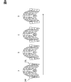
圧迫制御部217は、圧迫装置24での圧迫を行わせる場合に、より上方の袋体区画から順に空気を注入することで、図6のAからDに順に示すように、より上方の袋体区画から順に膨張させる。一例として、供給装置25と各袋体区画との間の管路に設けた電磁弁を開くタイミングをずらして、供給装置25から各袋体区画に空気を注入するタイミングをずらすことで実現すればよい。詳しくは、袋体区画241R,241Lに同時に空気を注入し始めた後、遅れて袋体区画242R,242Lに同時に空気を注入する。その後、遅れて袋体区画243R,243Lに同時に空気を注入し、最後に袋体区画244R,244Lに同時に空気を注入する。これによれば、呼気時に人体の上方から下方へ向けて幅が順番に絞られる胸郭の生理的な動きに合わせてドライバの胸郭を側方から圧迫することが可能になる。従って、ドライバの呼気をより深く長く行わせることが容易になる。 When the compression device 24 performs compression, the compression control unit 217 sequentially injects air from the upper bag section, so that the upper bag body as shown in order from A to D in FIG. Inflate the compartments one by one. As an example, by shifting the timing of opening the electromagnetic valve provided in the pipeline between the supply device 25 and each bag compartment, and shifting the timing of injecting air from the supply device 25 into each bag compartment, good. Specifically, air is simultaneously injected into the bag sections 241R and 241L, and then air is simultaneously injected into the bag sections 242R and 242L with a delay. After that, the bag sections 243R and 243L are simultaneously infused with air, and finally the bag sections 244R and 244L are simultaneously infused with air. According to this, it becomes possible to press the driver's ribcage from the side in accordance with the physiological movement of the ribcage, which narrows in order from the top to the bottom of the human body during exhalation. Therefore, it becomes easier to cause the driver to exhale deeper and longer.

圧迫制御部217は、圧迫装置24での圧迫を開始させた後、圧迫を開始させてからの経過時間が設定時間に達する場合に、圧迫装置24での圧迫を終了させる。圧迫を開始させてからの経過時間とは、供給装置25からの空気の注入を開始してからの時間とすればよい。経過時間は、タイマ回路でカウントすればよい。圧迫制御部217は、圧迫装置24での圧迫を終了させる場合には、排気弁を開くことで、圧迫装置24の全袋体区画からの膨張空気の排気を同時に開始させればよい。 After the compression by the compression device 24 is started, the compression control unit 217 ends the compression by the compression device 24 when the elapsed time from the start of compression reaches the set time. The elapsed time from the start of compression may be the time from the start of injection of air from the supply device 25 . The elapsed time can be counted by a timer circuit. When the compression by the compression device 24 is to be terminated, the compression control section 217 may simultaneously start exhausting the expanded air from all the bag compartments of the compression device 24 by opening the exhaust valves.

圧迫制御部217は、圧迫装置24での圧迫を開始させて圧迫を終了させるサイクルを繰り返すごとに、設定時間を予め定まった目標値に向けて段階的に長くしていくことが好ましい。ここで言うところの目標値は、リフレッシュ効果及び/又はリラックス効果が期待される呼気の長さに相当する値とすればよい。設定時間を目標値に向けて段階的に長くする構成を採用する場合には、各設定時間は、初期の設定時間と目標値との差分を段階数で除算した値を、段階数分だけ初期の設定時間に加算することで設定すればよい。初期の設定時間は、目標値よりも短い時間であればよい。初期の設定時間は、例えば平均的な人の呼気の長さとする等、任意に設定可能である。 It is preferable that the compression control unit 217 gradually lengthens the set time toward a predetermined target value each time the cycle of starting and ending compression by the compression device 24 is repeated. The target value referred to here may be a value corresponding to the length of exhalation for which a refreshing effect and/or a relaxing effect is expected. When adopting a configuration in which the set time is lengthened step by step toward the target value, each set time is obtained by dividing the difference between the initial set time and the target value by the number of steps. can be set by adding to the set time of . The initial set time may be any time shorter than the target value. The initial set time can be arbitrarily set, for example, the length of expiration of an average person.

なお、設定時間を目標値に向けて段階的に長くせずに、設定時間を目標値に固定する構成としてもよい。しかしながら、実際のドライバの呼気の長さと目標値との乖離が大きい場合、急激にこの目標値にドライバの呼気の長さを合わせることが難しい。よって、設定時間を目標値に向けて段階的に長くすることで、目標値にドライバの呼気の長さを合わせやすくことが好ましい。 It should be noted that the set time may be fixed at the target value instead of gradually lengthening the set time toward the target value. However, if there is a large divergence between the actual length of the driver's expiration and the target value, it is difficult to abruptly match the length of the driver's expiration to the target value. Therefore, it is preferable that the length of the driver's exhalation be easily adjusted to the target value by lengthening the set time step by step toward the target value.

圧迫制御部217は、圧迫装置24での圧迫を開始させた後、圧力取得部215で取得する圧力が閾値以上となる場合に、圧迫装置24での圧迫を終了させるとともに、設定時間が目標値に達していない場合であっても、設定時間を段階的に長くするのを中止することが好ましい。この場合、設定時間は、前回の設定時間に戻して固定すればよい。ここで言うところの閾値とは、圧迫装置24での圧迫中にドライバの吸気が開始されたことか否かを区別する閾値であって、任意に設定可能な値である。 After the compression by the compression device 24 is started, the compression control unit 217 terminates the compression by the compression device 24 when the pressure acquired by the pressure acquisition unit 215 is equal to or higher than the threshold value, and the set time reaches the target value. It is preferable to stop increasing the set time step by step even if the set time is not reached. In this case, the set time may be returned to the previous set time and fixed. The threshold referred to here is a threshold for distinguishing whether or not the driver has started to inhale during compression by the compression device 24, and is a value that can be set arbitrarily.

また、圧迫制御部217は、圧迫装置24での圧迫を開始させた後、圧力取得部215で取得する圧力の単位時間あたりの上昇率が閾値以上となる場合に、圧迫装置24での圧迫を終了させるとともに、設定時間が目標値に達していない場合であっても、設定時間を段階的に長くするのを中止する構成としてもよい。この場合も、設定時間は、前回の設定時間に戻して固定すればよい。ここで言うところの閾値とは、圧迫装置24での圧迫中にドライバの吸気が開始されたことか否かを区別する閾値であって、任意に設定可能な値である。 Further, after starting compression with the compression device 24, the compression control unit 217 starts compression with the compression device 24 when the increase rate per unit time of the pressure acquired by the pressure acquisition unit 215 is equal to or greater than the threshold. Even if the set time has not reached the target value, the stepwise lengthening of the set time may be stopped. Also in this case, the set time may be returned to the previous set time and fixed. The threshold referred to here is a threshold for distinguishing whether or not the driver has started to inhale during compression by the compression device 24, and is a value that can be set arbitrarily.

ドライバの吸気を開始する場合、胸郭は体の幅方向に広がる。よって、圧迫装置24での圧迫中にドライバが呼気の限界に達して吸気を開始する場合、圧力取得部215で取得する圧力は上昇する。従って、以上の構成によれば、圧迫装置24での圧迫による呼気の長さの延長がドライバにとって限界に達する場合に、圧迫を終了させるとともに圧迫による呼気の長さの延長も中止することが可能になる。従って、ドライバにとっての息苦しさを抑えつつ、ドライバの呼気をより深く長く行わせることが可能になる。なお、閾値との比較に圧力取得部215で取得する圧力の単位時間あたりの上昇率を用いると、ドライバの体格による圧力の差にかかわらず、より精度良くドライバが吸気を開始する場合に、圧迫を終了させるとともに圧迫による呼気の長さの延長も中止することが可能になる。 When the driver begins to inhale, the ribcage expands across the width of the body. Therefore, when the driver reaches the limit of exhalation during compression by the compression device 24 and begins to inhale, the pressure acquired by the pressure acquisition unit 215 increases. Therefore, according to the above configuration, when the extension of the expiration length due to compression by the compression device 24 reaches the limit for the driver, it is possible to end the compression and stop the extension of the expiration length due to compression. become. Therefore, it is possible to allow the driver to exhale deeper and longer while suppressing the suffocation of the driver. Note that if the rate of increase per unit time of the pressure acquired by the pressure acquisition unit 215 is used for comparison with the threshold value, regardless of the pressure difference due to the physique of the driver, when the driver starts to inhale more accurately, the compression It is possible to terminate the extension of the expiratory length by compression as well as to stop the extension of the expiratory length by compression.

なお、ここでの閾値との比較に用いる圧力は、各袋体区画に設けた圧力センサ26のうちの、最下部の袋体区画である袋体区画244R及び/又は袋体区画244Lに設けた圧力センサ26で検出した圧力とすればよい。これは、吸気時には下方から胸郭の幅が広がり始めるためである。 The pressure used for comparison with the threshold here is provided in the bag section 244R and/or the bag section 244L, which is the lowest bag section among the pressure sensors 26 provided in each bag section. The pressure detected by the pressure sensor 26 may be used. This is because the ribcage begins to widen from below during inspiration.

<HCU21での呼吸支援関連処理>
続いて、図7のフローチャートを用いて、HCU21での呼吸支援関連処理の流れの一例について説明を行う。図7のフローチャートは、例えば、自車の内燃機関又はモータジェネレータを始動させるためのスイッチ(以下、パワースイッチ)がオンになった場合にHCU21の電源もオンになり開始する構成とすればよい。他にも、操作デバイス23を介して呼吸支援関連処理を実行する機能のオンオフの設定を切り替えることができる構成の場合には、呼吸支援関連処理を実行する機能がオンとなっていることも条件に加える構成とすればよい。また、図7では、例えば心身状態特定部211でのドライバの心身状態の特定,負荷状況特定部213での運転負荷の高い状況の特定,身体的緊張特定部212での身体的な緊張の特定は、逐次行っているものとすればよい。
<Respiratory support related processing in HCU 21>
Next, an example of the flow of respiratory support-related processing in the HCU 21 will be described using the flowchart of FIG. 7 . The flowchart of FIG. 7 may be configured such that, for example, when a switch (hereinafter referred to as a power switch) for starting the internal combustion engine or motor generator of the vehicle is turned on, the HCU 21 is also turned on and started. In addition, in the case of a configuration in which the on/off setting of the function for executing respiratory support-related processing can be switched via the operation device 23, the function for executing respiratory support-related processing must also be turned on. It may be configured to be added to. Further, in FIG. 7, for example, the mental and physical condition of the driver is specified by the mental and physical condition specifying unit 211, the driving load is specified by the load condition specifying unit 213, and the physical tension is specified by the physical tension specifying unit 212. should be performed sequentially.

まず、ステップS1では、トリガ検出部214でトリガを検出した場合(S1でYES)には、ステップS2に移る。一方、トリガ検出部214でトリガを検出していない場合(S1でNO)には、ステップS4に移る。 First, in step S1, when the trigger detection unit 214 detects a trigger (YES in S1), the process proceeds to step S2. On the other hand, if the trigger detection unit 214 has not detected a trigger (NO in S1), the process proceeds to step S4.

ステップS2では、負荷状況特定部213が運転負荷の高い状況を特定した場合(S2でYES)には、ステップS4に移る。一方、負荷状況特定部213が運転負荷の高い状況を特定していない場合(S2でNO)には、ステップS3に移る。 In step S2, when the load condition identification unit 213 identifies a high operating load condition (YES in S2), the process proceeds to step S4. On the other hand, if the load condition identifying unit 213 has not identified a high operating load condition (NO in S2), the process proceeds to step S3.

ステップS3では、身体的緊張特定部212が身体的な緊張を特定した場合(S3でYES)には、ステップS4に移る。一方、身体的緊張特定部212が身体的な緊張を特定していない場合(S3でNO)には、ステップS5に移る。なお、S2とS3との処理は順番が入れ替わった構成としてもよい。 In step S3, when the physical tension identifying unit 212 identifies physical tension (YES in S3), the process proceeds to step S4. On the other hand, if the physical tension identifying unit 212 has not identified physical tension (NO in S3), the process proceeds to step S5. Note that the order of the processes of S2 and S3 may be reversed.

ステップS4では、呼吸支援関連処理の終了タイミングであった場合(S4でYES)には、呼吸支援関連処理を終了する。一方、呼吸支援関連処理の終了タイミングでなかった場合(S4でNO)には、S1に戻って処理を繰り返す。ここでの呼吸支援関連処理の終了タイミングの一例としては、自車のパワースイッチがオフになったこと,呼吸支援関連処理を実行する機能がオフの設定に切り替わったこと等がある。 In step S4, if it is time to end the respiratory support related process (YES in S4), the respiratory support related process is terminated. On the other hand, if it is not the end timing of the respiratory support related process (NO in S4), the process returns to S1 and repeats the process. An example of the end timing of the respiratory support related processing here is that the power switch of the own vehicle is turned off, or that the function for executing the respiratory support related processing is switched off.

ステップS5では、圧迫制御部217が初期の設定時間を設定する。ステップS6では、圧迫制御部217が、呼気タイミング特定部216で特定する呼気のタイミングを起点として、圧迫装置24での圧迫を開始させる。 In step S5, the compression control section 217 sets an initial set time. In step S<b>6 , the compression control section 217 causes the compression device 24 to start compressing with the expiration timing specified by the expiration timing specifying section 216 as a starting point.

ステップS7では、圧迫制御部217が、圧力取得部215で取得する圧力と、この圧力についての閾値とを比較する。そして、この圧力がこの閾値以上となる場合(S7でYES)には、ステップS13に移る。一方、この圧力がこの閾値未満の場合(S7でNO)には、ステップS8に移る。 In step S7, the compression control unit 217 compares the pressure acquired by the pressure acquisition unit 215 with a threshold for this pressure. If this pressure is greater than or equal to this threshold value (YES in S7), the process proceeds to step S13. On the other hand, if this pressure is less than this threshold value (NO in S7), the process proceeds to step S8.

ステップS8では、圧迫制御部217が、S6で圧迫装置24での圧迫を開始してからの経過時間と設定時間とを比較する。そして、この経過時間がこの設定時間に到達した場合(S8でYES)には、ステップS9に移る。一方、この経過時間がこの設定時間に到達していない場合(S8でNO)には、S7に戻って処理を繰り返す。 In step S8, the compression control unit 217 compares the elapsed time from the start of compression by the compression device 24 in S6 with the set time. When the elapsed time reaches the set time (YES in S8), the process proceeds to step S9. On the other hand, if the elapsed time has not reached the set time (NO in S8), the process returns to S7 to repeat the process.

ステップS9では、圧迫制御部217が、圧迫装置24での圧迫を終了させる。ステップS10では、圧迫制御部217が、現在設定している設定時間と目標値とを比較する。そして、この設定時間が目標値に到達した場合(S10でYES)には、ステップS11に移る。一方、この設定時間が目標値に到達していない場合(S10でNO)には、ステップS12に移る。 In step S<b>9 , the compression control section 217 terminates the compression by the compression device 24 . In step S10, the compression control unit 217 compares the set time currently set with the target value. When the set time reaches the target value (YES in S10), the process proceeds to step S11. On the other hand, if the set time has not reached the target value (NO in S10), the process proceeds to step S12.

ステップS11では、圧迫制御部217が、現在設定している設定時間に設定時間を固定する。つまり、設定時間を目標値に固定する。そして、ステップS15に移る。ステップS12では、圧迫制御部217が、現在設定している設定時間を長く変更する。一例として、S5で設定した初期の設定時間と目標値との差分を所定の数で除算した値だけ長く変更する。そして、ステップS15に移る。ここで言うところの所定の数とは、2以上の正の整数であればよく、任意に設定可能であるものとする。 In step S11, the compression control unit 217 fixes the set time to the currently set set time. That is, the set time is fixed at the target value. Then, the process moves to step S15. In step S12, the compression control unit 217 increases the currently set time. As an example, the difference between the initial set time set in S5 and the target value is lengthened by a value obtained by dividing the difference by a predetermined number. Then, the process moves to step S15. The predetermined number referred to here may be any positive integer of 2 or more and can be set arbitrarily.

S7で圧力が閾値以上であった場合に行われる処理であるステップS13では、圧迫制御部217が、圧迫装置24での圧迫を終了させる。つまり、S6で圧迫装置24での圧迫を開始してからの経過時間が設定時間に到達していなくても、圧力取得部215で取得する圧力が閾値以上の場合に、圧迫装置24での圧迫を終了させる。 In step S13, which is the process performed when the pressure is equal to or greater than the threshold value in S7, the compression control unit 217 terminates the compression by the compression device 24. FIG. That is, even if the elapsed time from the start of compression by the compression device 24 in S6 has not reached the set time, if the pressure acquired by the pressure acquisition unit 215 is equal to or greater than the threshold, the compression by the compression device 24 terminate.

ステップS14では、圧迫制御部217が、現在設定している設定時間が初期の設定時間でない場合には、前回設定した設定時間に戻して設定時間を固定する。圧迫制御部217は、現在設定している設定時間が初期の設定時間である場合には、初期の設定時間に設定時間を固定すればよい。 In step S14, if the currently set time is not the initial set time, the compression control unit 217 restores the previously set time and fixes the set time. If the currently set time is the initial set time, the compression control unit 217 may fix the set time to the initial set time.

ステップS15では、呼吸支援関連処理の終了タイミングであった場合(S15でYES)には、呼吸支援関連処理を終了する。一方、呼吸支援関連処理の終了タイミングでなかった場合(S15でNO)には、S6に戻って処理を繰り返す。ここでの呼吸支援関連処理の終了タイミングの一例としては、自車のパワースイッチがオフになったこと,呼吸支援関連処理を実行する機能がオフの設定に切り替わったこと等がある。また、呼吸運動を支援してリラックスさせたりリフレッシュさせたりすることが必要な心身状態を心身状態特定部211で特定したことをトリガとした場合には、この心身状態が改善したことを終了タイミングとしてもよい。さらに、S6~S15のサイクルが一定回数以上繰り返されたこと,最初にS6で圧迫が開始されてからの経過時間が一定時間に到達したこと等を終了タイミングとしてもよい。 In step S15, if it is time to end the respiratory support related process (YES in S15), the respiratory support related process ends. On the other hand, if it is not the end timing of the respiratory support related process (NO in S15), the process returns to S6 and repeats the process. An example of the end timing of the respiratory support related processing here is that the power switch of the own vehicle is turned off, or that the function for executing the respiratory support related processing is switched off. If the psychosomatic condition specifying unit 211 identifies a psychosomatic condition that requires relaxation or refreshment by assisting breathing exercise as a trigger, the improvement of the psychosomatic condition is set as the end timing. good too. Furthermore, the end timing may be that the cycle of S6 to S15 has been repeated a certain number of times or more, or that the elapsed time from the start of compression in S6 has reached a certain period of time, or the like.

<実施形態1のまとめ>
実施形態1の構成によれば、圧迫装置24は、ドライバが着座するシートSeのシートバックSBの両側に設けられるサイドサポートSSR,SSLにそれぞれ設けられて、シートバックSBの幅方向の内側に向けて圧迫を行う。よって、圧迫装置24で圧迫を行うと、シートSeに着座するドライバをシートバックSBの幅方向の内側に向けて圧迫することになる。この場合、ドライバの胸郭を側方から圧迫することになる。ドライバの胸郭を側方から圧迫すると、胸郭の幅方向の縮小運動を促すことで、呼気運動を支援することができる。
<Summary of Embodiment 1>
According to the configuration of the first embodiment, the compression devices 24 are provided on the side supports SSR and SSL provided on both sides of the seat back SB of the seat Se on which the driver sits, and extend inward in the width direction of the seat back SB. apply pressure. Therefore, when the compression device 24 performs compression, the driver seated on the seat Se is pressed inward in the width direction of the seat back SB. In this case, the chest of the driver is pressed from the side. When the driver's ribcage is compressed from the side, it is possible to assist the expiratory movement by promoting contraction of the ribcage in the width direction.

圧迫制御部217では、圧迫装置24での圧迫の期間を目標値に向けて延長していくので、ドライバの呼気がより深く長くように呼吸運動を支援することができる。ドライバの呼気がより深く長くなると、交感神経よりも副交感神経が優位となり、リラックス効果が得られる。さらに、ドライバの呼気がより深く長くなると、吸気時に肺に取り込む酸素量が増すため、リフレッシュ効果も得られる。 Since the compression control unit 217 extends the period of compression by the compression device 24 toward the target value, it is possible to assist the driver's breathing exercise so that the exhalation becomes deeper and longer. As the driver's exhalation becomes deeper and longer, the parasympathetic nerves become dominant over the sympathetic nerves, resulting in a relaxing effect. In addition, the deeper and longer the driver's exhalation is, the more oxygen is taken into the lungs during inspiration, resulting in a refreshing effect.

また、ドライバの胸郭を側方から圧迫して胸郭の幅方向の縮小運動を促したとしても、ドライバの姿勢は前後に傾きにくい。よって、圧迫装置24での圧迫によってドライバが運転姿勢から逸脱した姿勢となりにくい。その結果、運転操作中にドライバの呼吸を支援する場合であっても、このドライバによる運転操作を妨げにくくすることが可能になる。 In addition, even if the driver's ribcage is compressed from the side to encourage contraction of the ribcage in the width direction, the driver's posture is unlikely to tilt forward or backward. Therefore, it is difficult for the driver to deviate from the driving posture due to the compression by the compression device 24 . As a result, even when the breathing of the driver is assisted during the driving operation, it is possible to make it difficult for the driver to interfere with the driving operation.

(実施形態2)
実施形態1では、圧迫装置24での圧迫を行わせる場合に、より上方の袋体区画から順に空気を注入することで、より上方の袋体区画から順に膨張させる構成を示したが、必ずしもこれに限らない。例えば、下方の袋体区画ほど空気が注入される容量が大きく設けられていることで、より上方の袋体区画から順に膨張させる構成(以下、実施形態2)としてもよい。以下、実施形態2の構成について説明する。実施形態2の支援システム1は、圧迫装置24の構成が一部異なる点を除けば、実施形態1の支援システム1と同様である。
(Embodiment 2)
In the first embodiment, when the compressing device 24 performs compression, air is injected in order from the higher bag section, thereby inflating the bag section in order from the upper side, but this is not necessarily the case. is not limited to For example, a configuration in which air is injected into a lower bag section having a larger capacity is provided so that the bag section is inflated in order from the upper one (hereinafter referred to as Embodiment 2). The configuration of the second embodiment will be described below. The support system 1 of Embodiment 2 is the same as the support system 1 of Embodiment 1 except that the configuration of the compression device 24 is partially different.

ここで、図8を用いて、実施形態2における圧迫装置24の各袋体区画の配置の一例について説明を行う。図8は、実施形態2におけるシートSeの前方から見た圧迫装置24の配置の一例について説明を行うための図である。図8では、圧迫装置24の全袋体区画が膨張している状態を例に挙げている。なお、実施形態2におけるシートSeの側方から見た圧迫装置24の配置については、図4で示すような実施形態1と同様の配置であるものとする。 Here, an example of the arrangement of the bag sections of the compression device 24 according to the second embodiment will be described with reference to FIG. 8 . FIG. 8 is a diagram for explaining an example of the arrangement of the compression device 24 viewed from the front of the seat Se according to the second embodiment. FIG. 8 illustrates an example in which all bladder compartments of compression device 24 are inflated. The arrangement of the compression device 24 viewed from the side of the seat Se in the second embodiment is the same as that of the first embodiment as shown in FIG.

図8に示すように、各袋体区画のシートバックSBの上下方向の配置については、実施形態1と同様である。図8に示すように、圧迫装置24R,24Lの各袋体区画は、膨張時のシートバックSBの幅方向の内側に向けた突出量が、シートバックSBの下方向ほど大きくなるように設けられる。また、図8に示すように、圧迫装置24R,24Lの各袋体区画は、下方の袋体区画ほど空気が注入される容量が大きく設けられている。 As shown in FIG. 8, the vertical arrangement of the seat back SB in each bag section is the same as in the first embodiment. As shown in FIG. 8, each of the bag sections of the compression devices 24R and 24L is provided so that the amount of protrusion toward the inside in the width direction of the seat back SB when inflated increases toward the bottom of the seat back SB. . Further, as shown in FIG. 8, each of the bag sections of the compression devices 24R and 24L is provided with a larger capacity for injecting air toward the lower bag sections.

実施形態2における圧迫装置24R,24Lの各袋体区画は、空気が排気された非膨張時のシートバックSBの幅方向の内側に向けた突出量が各袋体区画で均等となるように設けられている構成とすればよい。 Each bag section of the compression devices 24R and 24L in the second embodiment is provided so that the amount of protrusion toward the inside in the width direction of the seat back SB when the air is exhausted and not inflated is uniform in each bag section. It should be the configuration that is specified.

実施形態2の圧迫制御部217は、圧迫装置24での圧迫を行わせる場合に、全袋体区画に空気を同時に注入することで、図9のEからHに順に示すように、より上方の袋体区画から順に膨張させる。これは、下方の袋体区画ほど容量が大きいため、全袋体区画に同時に空気が注入されると、下方の袋体区画ほど膨張に時間を要するためである。なお、実施形態2では、供給装置25と各袋体区画との間の管路に電磁弁を設けない構成としてもよい。 The compression control unit 217 of the second embodiment simultaneously injects air into all the bag compartments when the compression device 24 is caused to compress, thereby increasing the upper air volume as shown in order from E to H in FIG. 9 . The bag section is inflated in order. This is because lower bag compartments have larger capacities, and therefore take longer to inflate when air is injected into all of the bag compartments at the same time. In addition, in Embodiment 2, a configuration may be adopted in which no electromagnetic valve is provided in the pipeline between the supply device 25 and each bag section.

実施形態2の構成であっても、呼気時に人体の上方から下方へ向けて幅が順番に絞られる胸郭の生理的な動きに合わせてドライバの胸郭を側方から圧迫することが可能になる。従って、ドライバの呼気をより深く長く行わせることが容易になる。 Even with the configuration of the second embodiment, it is possible to press the chest of the driver from the side according to the physiological movement of the chest, which is gradually narrowed from the top to the bottom of the human body during exhalation. Therefore, it becomes easier to cause the driver to exhale deeper and longer.

(実施形態3)
実施形態1,2では、圧迫装置24での圧迫を行わせる場合に、より上方の袋体区画から順に膨張させる構成を示したが、実施形態1,2で説明した以外の態様で、より上方の袋体区画から順に膨張させる構成としてもよい。また、より上方の袋体区画から順に膨張させる構成に必ずしもこれに限らない。例えば、各袋体区画のシートバックSBの幅方向の内側に向けた突出量が略均等となるように各袋体区画を同時に膨張させる構成としてもよい。
(Embodiment 3)
In Embodiments 1 and 2, when compression is performed by the compression device 24, the structure is shown in which the upper bag section is inflated in order. It is good also as a structure which inflates in order from the bag body division of. In addition, the structure is not necessarily limited to the configuration in which the bag body sections are inflated in order from the higher one. For example, each bag section may be inflated at the same time so that the inward protrusion amount of the seat back SB in the width direction of each bag section is substantially uniform.

(実施形態4)
実施形態1~3では、袋体である圧迫装置24が複数の袋体区画に分かれている構成を示したが、必ずしもこれに限らない。例えば、袋体である圧迫装置24が複数の袋体区画に分かれていない構成(以下、実施形態4)としてもよい。実施形態4では、圧迫装置24R,24Lがそれぞれ一つの袋体である構成とすればよい。また、実施形態4では、圧迫装置24R,24Lの各袋体は、膨張時のシートバックSBの幅方向の内側に向けた突出量が、シートバックSBの下方向ほど大きくなるように設けられることが好ましい。これは、ドライバの胸郭の下方まで十分に圧迫することを可能にし、呼吸運動をさらに支援しやすくするためである。
(Embodiment 4)
In Embodiments 1 to 3, the configuration in which the compression device 24, which is a bag body, is divided into a plurality of bag body compartments is shown, but this is not necessarily the case. For example, a configuration in which the compression device 24, which is a bag body, is not divided into a plurality of bag body compartments (hereinafter referred to as Embodiment 4) may be adopted. In Embodiment 4, each of the compression devices 24R and 24L may be configured as one bag body. In the fourth embodiment, each of the bags of the compression devices 24R and 24L is provided so that the amount of protrusion toward the inside in the width direction of the seat back SB when inflated increases toward the bottom of the seat back SB. is preferred. This is to enable sufficient compression to the lower part of the driver's ribcage, making it easier to further support respiratory movements.

(実施形態5)
実施形態1~4では、袋体を用いて圧迫を行う構成を示したが、必ずしもこれに限らない。例えば、板状部材を用いて圧迫を行う構成(以下、実施形態5)としてもよい。以下、実施形態5の構成について説明する。
(Embodiment 5)
In Embodiments 1 to 4, the configuration for applying pressure using the bag has been described, but the configuration is not necessarily limited to this. For example, a configuration in which compression is performed using a plate member (hereinafter, Embodiment 5) may be employed. The configuration of the fifth embodiment will be described below.

<支援システム1aの概略構成>
以下、実施形態5について図面を用いて説明する。図10に示す支援システム1aは、HMIシステム2a、ロケータ3、ナビゲーション装置4、周辺監視センサ5、運転支援ECU6、及び車両状態センサ7を含んでいる。支援システム1aは、HMIシステム2の代わりにHMIシステム2aを含む点を除けば、実施形態1の支援システム1と同様である。
<Schematic configuration of support system 1a>
The fifth embodiment will be described below with reference to the drawings. The support system 1a shown in FIG. 10 includes an HMI system 2a, a locator 3, a navigation device 4, a surrounding monitoring sensor 5, a driving support ECU 6, and a vehicle state sensor 7. The support system 1a is the same as the support system 1 of the first embodiment except that the HMI system 2 is replaced with the HMI system 2a.

図10に示すように、HMIシステム2aは、HCU21a、生体センサ22、操作デバイス23、圧迫装置24a、及び圧力センサ26を含んでいる。HMIシステム2aは、HCU21及び圧迫装置24の代わりにHCU21a及び圧迫装置24aを含む点と、供給装置25を含まない点とを除けば、実施形態1のHMIシステム2と同様である。HCU21a、圧迫装置24a、及び圧力センサ26を含む構成が、呼吸支援装置20aにあたる。呼吸支援装置20aは、ドライバの呼吸運動を支援する。この呼吸支援装置20aが移動体用呼吸支援装置に相当する。 As shown in FIG. 10, the HMI system 2a includes an HCU 21a, a biosensor 22, an operating device 23, a compression device 24a, and a pressure sensor . The HMI system 2a is the same as the HMI system 2 of Embodiment 1, except that it includes an HCU 21a and a compression device 24a instead of the HCU 21 and compression device 24, and that it does not include a supply device 25. A configuration including the HCU 21a, the compression device 24a, and the pressure sensor 26 corresponds to the respiratory support device 20a. The respiratory support device 20a assists the driver's breathing exercise. This breathing support device 20a corresponds to a breathing support device for a moving body.

圧迫装置24aは、板状部材である。圧迫装置24aも、図2で示す圧迫装置24と同様に、右サイドサポートSSRと左サイドサポートSSLのそれぞれに内蔵される。以下では、右サイドサポートSSRに内蔵される圧迫装置24aを圧迫装置24aRとする。また、左サイドサポートSSLに内蔵される圧迫装置24aを圧迫装置24aLとする。 The compression device 24a is a plate-like member. Similar to the compression device 24 shown in FIG. 2, the compression device 24a is also incorporated in each of the right side support SSR and the left side support SSL. Hereinafter, the compression device 24a built into the right side support SSR is referred to as a compression device 24aR. Also, the compression device 24a incorporated in the left side support SSL is referred to as a compression device 24aL.

板状部材としての圧迫装置24aは、回転軸を中心に回動する。この回動は、モータ等のアクチュエータがHCU21aからの指示に従って駆動されることで行われる構成とすればよい。圧迫装置24aは、この回動によって、シートSeに着座するドライバの胸郭を側方から圧迫する。 The compression device 24a, which is a plate-like member, rotates about a rotation axis. This rotation may be performed by driving an actuator such as a motor in accordance with an instruction from the HCU 21a. By this rotation, the compression device 24a compresses the chest of the driver seated on the seat Se from the sides.

詳しくは、圧迫装置24aの回転軸は、シートバックSBの前後方向に沿った回転軸である。これにより、回転軸を中心にした圧迫装置24aの回動によって、シートバックSBの幅方向の内側に向けて、シートSeに着座するドライバの胸郭を圧迫することが可能になる。また、この回転軸は、右サイドサポートSSR及び左サイドサポートSSLの上方側と下方側とのうちの上方側に位置することが好ましい。これによれば、シートSeに着座するドライバの胸郭の下方ほど、シートバックSBの幅方向の内側に深く圧迫することが可能になる。従って、下方に向かうほど大きい胸郭の幅方向の運動範囲に合わせて、ドライバの胸郭の下方まで十分に圧迫することが可能になる。圧迫装置24aの設け方の詳細については、以下で説明を行う。 Specifically, the rotation axis of the compression device 24a is the rotation axis along the front-rear direction of the seat back SB. As a result, the rotation of the compression device 24a about the rotation axis allows the chest of the driver seated on the seat Se to be compressed inward in the width direction of the seat back SB. In addition, it is preferable that the rotation axis is positioned on the upper side between the upper side and the lower side of the right side support SSR and the left side support SSL. According to this, it is possible to press deeply inward in the width direction of the seatback SB toward the lower part of the ribcage of the driver seated on the seat Se. Therefore, it is possible to sufficiently press the lower part of the driver's ribcage in accordance with the movement range of the ribcage in the width direction, which increases downward. Details of how the compression device 24a is provided are described below.

<圧迫装置24aの設け方の例>
ここで、図11を用いて、実施形態5におけるシートSeへの圧迫装置24aの設け方の一例について説明を行う。図11は、実施形態5におけるシートSeの前方から見た圧迫装置24aの配置の一例について説明を行うための図である。図11では、シートSeに着座したドライバの胸郭に対する圧迫装置24aR,24aLの位置関係を模式的に示している。図11のAxが圧迫装置24aR,24aLの回転軸を示している。
<Example of how to provide the compression device 24a>
Here, an example of how to provide the compression device 24a to the seat Se in Embodiment 5 will be described with reference to FIG. FIG. 11 is a diagram for explaining an example of the arrangement of the compression device 24a viewed from the front of the seat Se according to the fifth embodiment. FIG. 11 schematically shows the positional relationship of the compression devices 24aR and 24aL with respect to the chest of the driver seated on the seat Se. Ax in FIG. 11 indicates the rotation axis of the compression devices 24aR and 24aL.

図11に示すように、圧迫装置24aR,24aLの上端は、シートSeに着座したドライバの中位胸郭にあたる高さに位置するように設けることが好ましい。つまり、圧迫装置24aR,24aLは、回転軸Axが、シートSeに着座したドライバの中位胸郭にあたる高さに位置するように設けることが好ましい。これは、中位胸郭を側方から圧迫して呼吸における中位胸郭の側方への動きを支援することで、呼吸運動をより支援しやすくするためである。一例として、ドライバの中位胸郭にあたる高さは、平均的なドライバの身長等から予め設定される値を用いればよい。 As shown in FIG. 11, the upper ends of the compression devices 24aR and 24aL are preferably provided at a height corresponding to the mid-thorax of the driver seated on the seat Se. That is, the compression devices 24aR and 24aL are preferably provided so that the rotation axis Ax is positioned at a height corresponding to the mid-thorax of the driver seated on the seat Se. This is because the lateral compression of the middle thorax supports the lateral movement of the middle thorax during respiration, thereby making it easier to support the respiratory movement. As an example, the height corresponding to the middle thorax of the driver may be a value preset based on the average height of the driver.

図11に示すように、圧迫装置24aR,24aLの下端も、シートSeに着座したドライバの中位胸郭にあたる高さに設けることが好ましい。これは、圧迫によって中位胸郭の側方への動きを支援しやすいためである。なお、圧迫装置24aR,24aLの下端を、シートSeに着座したドライバの下位胸郭にあたる高さにまで伸ばして設ける構成としてもよい。これによれば、呼吸における下位胸郭の側方への動きまで支援することで呼吸運動をさらに支援しやすくすることが可能になる。 As shown in FIG. 11, the lower ends of the compression devices 24aR and 24aL are also preferably provided at a height corresponding to the mid-thorax of the driver seated on the seat Se. This is because compression tends to support lateral movement of the mid-thorax. Note that the lower ends of the compression devices 24aR and 24aL may be extended to a height corresponding to the lower thorax of the driver seated on the seat Se. According to this, it becomes possible to further facilitate respiratory exercise by supporting lateral movement of the lower ribcage during respiration.

圧迫装置24aR,24aLは、圧迫のための回動を開始する前のデフォルトの状態でも、シートSeに着座したドライバの脇腹に接触できるように予め設計して設けられることが好ましい。これによれば、回転軸Axを中心にした圧迫装置24aR,24aLの回動によって、シートSeに着座したドライバの胸郭を上方から下方に順番に圧迫することが可能になる。この場合、呼気時に人体の上方から下方へ向けて幅が順番に絞られる胸郭の生理的な動きに合わせてドライバの胸郭を側方から圧迫することが可能になる。従って、ドライバの呼気をより深く長く行わせることが容易になる。 The compression devices 24aR and 24aL are preferably designed and provided in advance so that they can contact the flanks of the driver seated on the seat Se even in the default state before the rotation for compression is started. According to this, it is possible to sequentially compress the chest of the driver seated on the seat Se from above to below by rotating the compression devices 24aR and 24aL about the rotation axis Ax. In this case, it is possible to press the driver's ribcage from the side according to the physiological movement of the ribcage, which is gradually narrowed from the top to the bottom of the human body during exhalation. Therefore, it becomes easier to cause the driver to exhale deeper and longer.

実施形態5における圧力センサ26も、圧迫装置24aR,24aLの乗員を圧迫する側の面にそれぞれ設けられる構成とすればよい。一例として、圧力センサ26は、ドライバの吸気時に生じる圧力を迅速に検出可能とするため、少なくとも圧迫装置24aR,24aLの下方側に設けられることが好ましい。 The pressure sensors 26 in the fifth embodiment may also be configured to be provided on the surfaces of the compressing devices 24aR and 24aL on the side that compresses the occupant. As an example, the pressure sensor 26 is preferably provided at least below the compression devices 24aR and 24aL in order to be able to quickly detect the pressure generated when the driver inhales.

また、板状部材である圧迫装置24aR,24aLは、図12に示すように、乗員を圧迫する側の面が、ドライバの仮想的な胸郭の形状に沿って弓状に凹んだ形状となっていることが好ましい。図12は、実施形態5におけるシートSeの上方から見た圧迫装置24aの形状の一例について説明を行うための図である。これによれば、圧迫装置24aR,24aLでのドライバの圧迫時にドライバに接触する面を広くして不快感を抑えることが可能になる。 In addition, as shown in FIG. 12, the compression devices 24aR and 24aL, which are plate-like members, have surfaces on the side that compresses the occupant, which are recessed in an arcuate shape along the shape of the virtual chest of the driver. preferably. FIG. 12 is a diagram for explaining an example of the shape of the compression device 24a viewed from above the seat Se in the fifth embodiment. According to this, it is possible to widen the surface contacting the driver when the compression devices 24aR and 24aL press the driver, thereby suppressing discomfort.

<HCU21aの概略構成>
続いて、図13を用いて、HCU21aの概略構成について説明を行う。HCU21aは、図13に示すように、心身状態特定部211、身体的緊張特定部212、負荷状況特定部213、トリガ検出部214、圧力取得部215、呼気タイミング特定部216、及び圧迫制御部217aを機能ブロックとして備える。HCU21aは、圧迫制御部217の代わりに圧迫制御部217aを備える点を除けば、実施形態1のHCU21と同様である。
<Schematic configuration of HCU 21a>
Next, a schematic configuration of the HCU 21a will be described with reference to FIG. As shown in FIG. 13, the HCU 21a includes a mental and physical condition identification unit 211, a physical tension identification unit 212, a load condition identification unit 213, a trigger detection unit 214, a pressure acquisition unit 215, an expiration timing identification unit 216, and a compression control unit 217a. is provided as a function block. The HCU 21a is the same as the HCU 21 of the first embodiment, except that the compression control section 217 is replaced by a compression control section 217a.

圧迫制御部217aは、圧迫を行わせるのが圧迫装置24の代わりに圧迫装置24aになる点と、この違いによる処理の違いとを除けば、実施形態1の圧迫制御部217と同様である。以下では、実施形態1の圧迫制御部217と異なる点について説明を行う。 The compression control unit 217a is the same as the compression control unit 217 of the first embodiment, except that the compression device 24a performs compression instead of the compression device 24, and the processing is different due to this difference. Differences from the compression control unit 217 of the first embodiment will be described below.

圧迫制御部217aは、圧迫装置24aの動作を制御する。圧迫制御部217aは、アクチュエータを駆動させることによって圧迫装置24aを、回転軸Axを中心に回動させる。圧迫制御部217aは、図14に示すように、シートSeの前方から見て、圧迫装置24aRを反時計回り,圧迫装置24aLを時計回りに回動させることで、シートSeに着座するドライバの胸郭を側方から圧迫させる。図14は、実施形態5における圧迫装置24aでの圧迫の態様について説明するための図である。 The compression controller 217a controls the operation of the compression device 24a. The compression control unit 217a rotates the compression device 24a around the rotation axis Ax by driving the actuator. As shown in FIG. 14, the compression control unit 217a rotates the compression device 24aR counterclockwise and the compression device 24aL clockwise when viewed from the front of the seat Se, thereby adjusting the thorax of the driver seated on the seat Se. side pressure. FIG. 14 is a diagram for explaining the mode of compression by the compression device 24a according to the fifth embodiment.

一方、圧迫制御部217aは、シートSeの前方から見て、圧迫装置24aRを時計回り,圧迫装置24aLを反時計回りに回動させることで、シートSeに着座するドライバの胸郭の圧迫を終了させる。 On the other hand, the compression control unit 217a rotates the compression device 24aR clockwise and the compression device 24aL counterclockwise when viewed from the front of the seat Se, thereby completing compression of the chest of the driver seated on the seat Se. .

実施形態5の構成は、圧迫を袋体で行わせる代わりに板状部材で行わせる点を除けば、実施形態1と同様であるので、実施形態1と同様に、運転操作中にドライバの呼吸を支援する場合であっても、このドライバによる運転操作を妨げにくくすることが可能になる。 The configuration of Embodiment 5 is the same as Embodiment 1, except that compression is performed by a plate-like member instead of by a bag. Even in the case of assisting the driver, it is possible to make the driving operation by the driver less likely to be hindered.

(実施形態6)
実施形態5では、シートバックSBの前後方向に沿った回転軸Axを中心にした、板状部材としての圧迫装置24aの回動によってドライバの胸郭を圧迫する構成を示したが、必ずしもこれに限らない。例えば、シートバックSBの上下方向に沿った回転軸Axを中心にした、板状部材としての圧迫装置24aの回動によってドライバの胸郭を圧迫する構成(以下、実施形態6)としてもよい。以下、実施形態6の構成について説明する。実施形態6の支援システム1aは、圧迫装置24aの回転軸が異なる点を除けば、実施形態5の支援システム1aと同様である。
(Embodiment 6)
In the fifth embodiment, the configuration is shown in which the compression device 24a, which is a plate-like member, rotates about the rotation axis Ax along the longitudinal direction of the seat back SB to compress the driver's chest. do not have. For example, a configuration may be adopted in which the chest of the driver is compressed by rotating the compression device 24a as a plate member about the rotation axis Ax along the vertical direction of the seatback SB (hereinafter, Embodiment 6). The configuration of the sixth embodiment will be described below. The support system 1a of Embodiment 6 is similar to the support system 1a of Embodiment 5, except that the rotation axis of the compression device 24a is different.

ここで、図15を用いて、実施形態6におけるシートSeへの圧迫装置24aの設け方の一例について説明を行う。図15は、実施形態6におけるシートSeの上方から見た圧迫装置24aの配置の一例について説明を行うための図である。図15では、シートSeに着座したドライバの胸郭に対する圧迫装置24aR,24aLの位置関係を模式的に示している。図15のAxが実施形態6における圧迫装置24aR,24aLの回転軸を示している。 Here, an example of how to provide the compression device 24a to the seat Se in Embodiment 6 will be described with reference to FIG. FIG. 15 is a diagram for explaining an example of the arrangement of the compression device 24a viewed from above the seat Se according to the sixth embodiment. FIG. 15 schematically shows the positional relationship of the compression devices 24aR and 24aL with respect to the chest of the driver seated on the seat Se. Ax in FIG. 15 indicates the rotation axis of the compression devices 24aR and 24aL in the sixth embodiment.

実施形態6における圧迫装置24aの回転軸Axは、シートバックSBの上下方向に沿った回転軸である。これにより、回転軸Axを中心にした圧迫装置24aの回動によって、シートバックSBの幅方向の内側に向けて、シートSeに着座するドライバの胸郭を圧迫することが可能になる。また、この回転軸Axは、右サイドサポートSSR及び左サイドサポートSSLのシートバックSBよりも前方に突出した突端側とシートバックSB側とのうちのシートバックSB側に位置することが好ましい。これによれば、シートSeにドライバをホールドしつつ、ドライバの胸郭を側方から圧迫することが可能になる。 The rotation axis Ax of the compression device 24a in the sixth embodiment is the rotation axis along the vertical direction of the seat back SB. As a result, the rotation of the compression device 24a about the rotation axis Ax makes it possible to compress the chest of the driver seated on the seat Se inward in the width direction of the seat back SB. Further, it is preferable that the rotation axis Ax be positioned on the seat back SB side between the tip end side projecting forward from the seat back SB of the right side support SSR and the left side support SSL and the seat back SB side. According to this, it is possible to press the driver's chest from the side while holding the driver on the seat Se.

なお、実施形態6における圧迫装置24aR,24aLの上端と下端との位置は、実施形態5と同様とすればよい。実施形態6における圧力センサ26も、圧迫装置24aR,24aLの乗員を圧迫する側の面にそれぞれ設けられる構成とすればよい。一例として、圧力センサ26は、ドライバの吸気時に生じる圧力を迅速に検出可能とするため、少なくとも圧迫装置24aR,24aLの下方側に設けられることが好ましい。また、板状部材である圧迫装置24aR,24aLは、実施形態5で説明したのと同様に、乗員を圧迫する側の面が、ドライバの仮想的な胸郭の形状に沿って弓状に凹んだ形状となっていることが好ましい。 The positions of the upper ends and lower ends of the compression devices 24aR and 24aL in the sixth embodiment may be the same as in the fifth embodiment. The pressure sensors 26 in Embodiment 6 may also be configured to be provided on the surfaces of the compressing devices 24aR and 24aL on the side that compresses the occupant. As an example, the pressure sensor 26 is preferably provided at least below the compression devices 24aR and 24aL in order to be able to quickly detect the pressure generated when the driver inhales. In addition, the pressing devices 24aR and 24aL, which are plate-like members, have surfaces that press the occupant in an arcuate shape along the shape of the virtual chest of the driver, as described in the fifth embodiment. It is preferably shaped.

実施形態6における圧迫制御部217aも、アクチュエータを駆動させることによって圧迫装置24aを、回転軸Axを中心に回動させる。実施形態6における圧迫制御部217aは、図16に示すように、シートSeの上方から見て、圧迫装置24aRを反時計回り,圧迫装置24aLを時計回りに回動させることで、シートSeに着座するドライバの胸郭を側方から圧迫させる。図16は、実施形態6における圧迫装置24aでの圧迫の態様について説明するための図である。 The compression control unit 217a in the sixth embodiment also rotates the compression device 24a about the rotation axis Ax by driving the actuator. As shown in FIG. 16, the compression control unit 217a according to the sixth embodiment rotates the compression device 24aR counterclockwise and the compression device 24aL clockwise when viewed from above the seat Se, thereby allowing the user to sit on the seat Se. laterally compress the driver's chest. FIG. 16 is a diagram for explaining the mode of compression by the compression device 24a according to the sixth embodiment.

一方、実施形態6における圧迫制御部217aは、シートSeの上方から見て、圧迫装置24aRを時計回り,圧迫装置24aLを反時計回りに回動させることで、シートSeに着座するドライバの胸郭の圧迫を終了させる。 On the other hand, the compression control unit 217a in the sixth embodiment rotates the compression device 24aR clockwise and the compression device 24aL counterclockwise when viewed from above the seat Se, thereby adjusting the chest of the driver seated on the seat Se. Terminate compression.

実施形態6の構成は、回転軸Axの方向が異なるものの、シートSeに着座するドライバの胸郭を側方から圧迫できることは実施形態5と同様である。よって、実施形態5と同様に、運転操作中にドライバの呼吸を支援する場合であっても、このドライバによる運転操作を妨げにくくすることが可能になる。 Although the configuration of the sixth embodiment differs in the direction of the rotation axis Ax, it is the same as that of the fifth embodiment in that the chest of the driver seated on the seat Se can be laterally compressed. Therefore, as in the fifth embodiment, even when the breathing of the driver is assisted during the driving operation, it is possible to make it difficult for the driver to interfere with the driving operation.

(実施形態7)
実施形態6では、シートバックSBの上下方向に沿った回転軸Axを中心にした、板状部材としての圧迫装置24aの回動によってドライバの胸郭を圧迫する構成を示したが、必ずしもこれに限らない。例えば、シートバックSBの上下方向に沿った軸を前傾させた回転軸Axを中心にした、板状部材としての圧迫装置24aの回動によってドライバの胸郭を圧迫する構成(以下、実施形態7)としてもよい。以下、実施形態7の構成について説明する。実施形態7の支援システム1aは、圧迫装置24aの回転軸が異なる点を除けば、実施形態6の支援システム1aと同様である。
(Embodiment 7)
In the sixth embodiment, the configuration is shown in which the compression device 24a, which is a plate-shaped member, rotates around the rotation axis Ax along the vertical direction of the seat back SB to compress the driver's chest, but this is not necessarily the case. do not have. For example, a configuration for compressing the driver's chest by rotating the compressing device 24a as a plate-like member around the rotation axis Ax, which is the vertical axis of the seatback SB that is tilted forward (hereinafter referred to as Embodiment 7). ). The configuration of the seventh embodiment will be described below. The support system 1a of Embodiment 7 is similar to the support system 1a of Embodiment 6, except that the rotation axis of the compression device 24a is different.

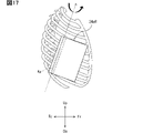
ここで、図17を用いて、実施形態7におけるシートSeへの圧迫装置24aの設け方の一例について説明を行う。図17は、実施形態6におけるシートSeの右側方から見た圧迫装置24aの配置の一例について説明を行うための図である。図17では、シートSeに着座したドライバの胸郭に対する圧迫装置24aRの位置関係を模式的に示している。図17のAxが実施形態7における圧迫装置24aRの回転軸を示している。 Here, an example of how to provide the compression device 24a to the sheet Se in Embodiment 7 will be described with reference to FIG. FIG. 17 is a diagram for explaining an example of the arrangement of the compression device 24a viewed from the right side of the seat Se according to the sixth embodiment. FIG. 17 schematically shows the positional relationship of the compression device 24aR with respect to the chest of the driver seated on the seat Se. Ax in FIG. 17 indicates the rotation axis of the compression device 24aR in the seventh embodiment.

実施形態7における圧迫装置24aの回転軸Axは、シートバックSBの上下方向に沿った軸を、シートバックSBよりも前方に傾けた回転軸である。回転軸をシートバックSBよりも前方に傾ける度合いについては任意の値とすればよい。これにより、回転軸Axを中心にした圧迫装置24aの回動によって、シートバックSBの幅方向の内側に向けて、シートSeに着座するドライバの胸郭を圧迫するとともに、シートバックSBの前後方向の後方に向けて、シートSeに着座するドライバの胸郭を圧迫することも可能になる。 The rotation axis Ax of the compression device 24a in the seventh embodiment is a rotation axis that extends along the vertical direction of the seat back SB and is tilted forward from the seat back SB. An arbitrary value may be set for the degree to which the rotation axis is inclined forward from the seat back SB. As a result, the compression device 24a rotates about the rotation axis Ax to compress the thorax of the driver seated on the seat Se inward in the width direction of the seat back SB, and to move the seat back SB forward and backward. It is also possible to press the chest of the driver seated on the seat Se toward the rear.

なお、実施形態7における圧迫装置24aR,24aLの上端と下端との位置は、実施形態5と同様とすればよい。実施形態7における圧力センサ26も、圧迫装置24aR,24aLの乗員を圧迫する側の面にそれぞれ設けられる構成とすればよい。一例として、圧力センサ26は、ドライバの吸気時に生じる圧力を迅速に検出可能とするため、少なくとも圧迫装置24aR,24aLの下方側に設けられることが好ましい。また、板状部材である圧迫装置24aR,24aLは、実施形態5で説明したのと同様に、乗員を圧迫する側の面が、ドライバの仮想的な胸郭の形状に沿って弓状に凹んだ形状となっていることが好ましい。 The positions of the upper ends and the lower ends of the compression devices 24aR and 24aL in the seventh embodiment may be the same as in the fifth embodiment. The pressure sensors 26 in Embodiment 7 may also be configured to be provided on the surfaces of the compressing devices 24aR and 24aL on the side that compresses the occupant. As an example, the pressure sensor 26 is preferably provided at least below the compression devices 24aR and 24aL in order to be able to quickly detect the pressure generated when the driver inhales. In addition, the pressing devices 24aR and 24aL, which are plate-like members, have surfaces that press the occupant in an arcuate shape along the shape of the virtual chest of the driver, as described in the fifth embodiment. It is preferably shaped.

実施形態7における圧迫制御部217aも、アクチュエータを駆動させることによって圧迫装置24aを、回転軸Axを中心に回動させる。実施形態7における圧迫制御部217aは、シートSeの上方から見て、圧迫装置24aRを反時計回り,圧迫装置24aLを時計回りに回動させることで、シートSeに着座するドライバの胸郭を側方及び前方から圧迫させる。一方、実施形態7における圧迫制御部217aは、シートSeの上方から見て、圧迫装置24aRを時計回り,圧迫装置24aLを反時計回りに回動させることで、シートSeに着座するドライバの胸郭の圧迫を終了させる。 The compression controller 217a in Embodiment 7 also rotates the compression device 24a about the rotation axis Ax by driving the actuator. The compression control unit 217a in Embodiment 7 rotates the compression device 24aR counterclockwise and the compression device 24aL clockwise when viewed from above the seat Se, thereby laterally moving the chest of the driver seated on the seat Se. and apply pressure from the front. On the other hand, the compression control unit 217a in the seventh embodiment rotates the compression device 24aR clockwise and the compression device 24aL counterclockwise when viewed from above the seat Se, thereby adjusting the chest of the driver seated on the seat Se. Terminate compression.

実施形態7の構成は、回転軸Axの方向が異なるものの、シートSeに着座するドライバの胸郭を側方から圧迫できることは実施形態7と同様である。よって、実施形態7と同様に、運転操作中にドライバの呼吸を支援する場合であっても、このドライバによる運転操作を妨げにくくすることが可能になる。また、実施形態7の構成によれば、シートバックSBの前後方向の後方に向けても、シートSeに着座するドライバの胸郭を圧迫しやすくなる。よって、胸郭の厚さ方向の縮小運動も促すことで、呼気運動をさらに支援することができる。 Although the configuration of the seventh embodiment differs in the direction of the rotation axis Ax, it is the same as that of the seventh embodiment in that it can laterally press the chest of the driver seated on the seat Se. Therefore, as in the seventh embodiment, even when the driver's breathing is assisted during the driving operation, it is possible to make it difficult for the driver to interfere with the driving operation. Further, according to the configuration of the seventh embodiment, even when the seat back SB is directed rearward in the front-rear direction, it is easy to press the chest of the driver seated on the seat Se. Therefore, expiratory movement can be further assisted by promoting contraction movement of the ribcage in the thickness direction.

(実施形態8)
前述の実施形態では、袋体の膨張,板状部材の回動によってドライバの胸郭を圧迫する構成を示したが、必ずしもこれに限らない。シートSeに着座するドライバの胸郭を側方から圧迫することと、この圧迫から開放することとが可能な構成であれば、他の構成を採用してもよい。
(Embodiment 8)
In the above-described embodiment, the expansion of the bag body and the rotation of the plate-shaped member have shown a configuration in which the chest of the driver is compressed, but this is not necessarily the case. Any other configuration may be employed as long as it is a configuration capable of laterally compressing the chest of the driver seated on the seat Se and releasing the compression.

(実施形態9)
前述の実施形態では、圧迫制御部217,217aが、圧迫を開始させてからの経過時間が設定時間に達する場合に、圧迫装置24,24aでの圧迫を終了させる構成を示したが、必ずしもこれに限らない。例えば、圧迫を開始させてからの経過時間が設定時間に達することを、圧迫を終了させる条件として用いない構成としてもよい。
(Embodiment 9)
In the above-described embodiments, the compression controllers 217 and 217a terminate the compression with the compression devices 24 and 24a when the elapsed time from the start of compression reaches the set time, but this is not necessarily the case. is not limited to For example, a configuration may be adopted in which the fact that the elapsed time from the start of compression reaches a set time is not used as a condition for ending compression.

この場合、圧迫制御部217,217aが、圧迫を開始させた後、圧力取得部215で取得する圧力が閾値以上となる場合に、圧迫装置24,24aでの圧迫を終了させる構成とすればよい。ここで言うところの閾値とは、圧迫装置24,24aでの圧迫中にドライバの吸気が開始されたことか否かを区別する閾値であって、任意に設定可能な値である。 In this case, after the compression control units 217 and 217a start compression, if the pressure acquired by the pressure acquisition unit 215 is equal to or greater than the threshold, the compression by the compression devices 24 and 24a may be terminated. . The threshold referred to here is a threshold for distinguishing whether or not the driver has started to inhale during compression by the compression devices 24 and 24a, and is a value that can be set arbitrarily.

このような構成を採用した場合であっても、圧迫装置24,24aでの圧迫によってドライバの呼気運動を支援することで、ドライバの呼気をより深く長くすることが可能になる。よって、運転操作中にドライバの呼吸を支援する場合であっても、このドライバによる運転操作を妨げにくくすることが可能になる。 Even when such a configuration is adopted, the driver's exhalation can be made deeper and longer by assisting the driver's exhalation by pressing with the compression devices 24 and 24a. Therefore, even when the breathing of the driver is assisted during the driving operation, it is possible to make it difficult for the driver to interfere with the driving operation.

(実施形態10)
前述の実施形態では、呼気タイミング特定部216で呼気のタイミングを特定したタイミングで、圧迫装置24,24aでの圧迫を開始させる構成を示したが、必ずしもこれに限らない。例えば、呼気タイミング特定部216で逐次特定する呼気のタイミングから呼気の周期を学習し、学習した呼気のタイミングで、圧迫装置24,24aでの圧迫を開始させる構成としてもよい。
(Embodiment 10)
In the above-described embodiment, the configuration is shown in which the compression by the compression devices 24 and 24a is started at the timing specified by the expiration timing specifying unit 216, but this is not necessarily the case. For example, the expiration period may be learned from the expiration timings sequentially specified by the expiration timing specifying unit 216, and the compression devices 24 and 24a may start compression at the learned expiration timings.

(実施形態11)
前述の実施形態では、圧迫装置24での圧迫を実施させない条件として、身体的緊張特定部212でドライバの身体的な緊張を特定している場合及び負荷状況特定部213で運転負荷の高い状況を特定している場合を示したが、必ずしもこれに限らない。例えば、これらのうちのいずれかのみを圧迫装置24での圧迫を実施させない条件とする構成としてもよい。また、これらの条件以外の、胸郭の圧迫による呼吸運動の支援に適さない状態を、圧迫装置24での圧迫を実施させない条件としてもよい。
(Embodiment 11)
In the above-described embodiment, the conditions for preventing the compression device 24 from performing compression include the case where the physical tension identification unit 212 identifies the physical tension of the driver and the load condition identification unit 213 indicates a high driving load. Although a specific case is shown, it is not necessarily limited to this. For example, only one of these conditions may be set as a condition that the compression device 24 is not allowed to perform compression. In addition to these conditions, a condition that is not suitable for supporting respiratory exercise by compressing the chest may be set as a condition for not performing compression by the compression device 24 .

(実施形態12)
前述の実施形態では、圧迫装置24,24aで圧迫を行う対象をドライバとする場合の例を示したが、必ずしもこれに限らない。例えば、ドライバ以外の乗員も対象とする構成としてもよい。ドライバ以外の乗員を対象とする場合には、圧迫装置24での圧迫を実施させない条件として、負荷状況特定部213で運転負荷の高い状況を特定している場合を除外すればよい。
(Embodiment 12)
In the above-described embodiment, an example was shown in which the target to be compressed by the compression devices 24, 24a was the driver, but this is not necessarily the case. For example, it may be configured to target passengers other than the driver. In the case of occupants other than the driver, as a condition for not performing compression by the compression device 24, the case where the load condition identification unit 213 identifies a high driving load condition may be excluded.

(実施形態13)
前述の実施形態では、支援システム1,1aを自動車で用いる場合の例を示したが、必ずしもこれに限らない。例えば、サイドサポートを有するシートが搭載される車両であれば、自動車以外の車両で用いる構成としてもよい。例えば、鉄道車両等で用いる構成としてもよい。また、サイドサポートを有するシートが搭載される移動体であれば、車両以外の移動体で用いる構成としてもよい。例えば、航空機,船舶等で用いる構成としてもよい。
(Embodiment 13)
In the above-described embodiment, an example in which the support systems 1 and 1a are used in an automobile was shown, but the present invention is not necessarily limited to this. For example, as long as the vehicle is equipped with a seat having side supports, it may be configured to be used in a vehicle other than an automobile. For example, it may be configured to be used in a railroad vehicle or the like. Moreover, as long as it is a mobile body on which a seat having side supports is mounted, it may be configured to be used in a mobile body other than a vehicle. For example, it may be configured to be used in an aircraft, ship, or the like.

(実施形態14)
前述の実施形態では、呼吸支援関連処理をHCU21,21aで実行する構成を示したが、必ずしもこれに限らない。呼吸支援関連処理をHCU21,21a以外の電子制御装置で実行する構成としてもよい。
(Embodiment 14)
In the above-described embodiment, the HCU 21, 21a performs the respiratory support related processing, but the configuration is not necessarily limited to this. A configuration may be adopted in which the respiratory support-related processing is executed by an electronic control device other than the HCUs 21 and 21a.

なお、本開示は、上述した実施形態に限定されるものではなく、請求項に示した範囲で種々の変更が可能であり、異なる実施形態にそれぞれ開示された技術的手段を適宜組み合わせて得られる実施形態についても本開示の技術的範囲に含まれる。また、本開示に記載の制御部及びその手法は、コンピュータプログラムにより具体化された一つ乃至は複数の機能を実行するようにプログラムされたプロセッサを構成する専用コンピュータにより、実現されてもよい。あるいは、本開示に記載の装置及びその手法は、専用ハードウェア論理回路により、実現されてもよい。もしくは、本開示に記載の装置及びその手法は、コンピュータプログラムを実行するプロセッサと一つ以上のハードウェア論理回路との組み合わせにより構成された一つ以上の専用コンピュータにより、実現されてもよい。また、コンピュータプログラムは、コンピュータにより実行されるインストラクションとして、コンピュータ読み取り可能な非遷移有形記録媒体に記憶されていてもよい。 It should be noted that the present disclosure is not limited to the above-described embodiments, and can be modified in various ways within the scope of the claims, and can be obtained by appropriately combining technical means disclosed in different embodiments. Embodiments are also included in the technical scope of the present disclosure. The controller and techniques described in this disclosure may also be implemented by a special purpose computer comprising a processor programmed to perform one or more functions embodied by a computer program. Alternatively, the apparatus and techniques described in this disclosure may be implemented by dedicated hardware logic circuitry. Alternatively, the apparatus and techniques described in this disclosure may be implemented by one or more special purpose computers configured in combination with a processor executing a computer program and one or more hardware logic circuits. The computer program may also be stored as computer-executable instructions on a computer-readable non-transitional tangible recording medium.

1,1a 支援システム、2,2a HMIシステム、20,20a 呼吸支援装置(移動体用呼吸支援装置)、21,21a HCU、22 生体センサ、24,24a,24L,24R,24aR,24aL 圧迫装置(圧迫部)、25 供給装置、26 圧力センサ、211 心身状態特定部、212 身体的緊張特定部(緊張特定部)、213 負荷状況特定部、214 トリガ検出部、215 圧力取得部、216 呼気タイミング特定部、217,217a 圧迫制御部、241R,242R,243R,244R,241L,242L,243L,244L 袋体区画、Se シート、SB シートバック、SSR,SSL サイドサポート 1, 1a support system, 2, 2a HMI system, 20, 20a respiratory support device (moving body respiratory support device), 21, 21a HCU, 22 biosensor, 24, 24a, 24L, 24R, 24aR, 24aL compression device ( compression unit), 25 supply device, 26 pressure sensor, 211 psychosomatic condition identification unit, 212 physical tension identification unit (tension identification unit), 213 load condition identification unit, 214 trigger detection unit, 215 pressure acquisition unit, 216 expiration timing identification Part 217, 217a Compression control part 241R, 242R, 243R, 244R, 241L, 242L, 243L, 244L Bag body section Se Seat SB Seat back SSR, SSL Side support

Claims (19)

移動体で用いられ、
前記移動体の乗員が着座するシート(Se)の背もたれ部(SB)の両側に設けられて前記背もたれ部よりも前方に突出した突出部であるサイドサポート(SSR,SSL)にそれぞれ設けられて、前記背もたれ部の幅方向の内側に向けて圧迫可能な圧迫部(24,24a)と、
前記圧迫部の動作を制御する圧迫制御部(217,217a)とを備え、
前記圧迫制御部での制御によって前記圧迫部で前記背もたれ部の幅方向の内側に向けて圧迫を行わせることで、前記シートに着座する前記乗員の胸郭を前記背もたれ部の幅方向の内側に向けて圧迫する一方、前記圧迫制御部での制御によって前記圧迫部での前記圧迫を終了させることで、前記シートに着座する前記乗員の胸郭を前記圧迫から開放する移動体用呼吸支援装置。
used in mobiles,
The side supports (SSR, SSL), which are protruding portions that are provided on both sides of the backrest portion (SB) of the seat (Se) on which the occupant of the moving body sits and protrude forward from the backrest portion, are provided with the compression parts (24, 24a) that can be compressed toward the inside in the width direction of the backrest;
A compression control unit (217, 217a) that controls the operation of the compression unit,
The thorax of the occupant seated on the seat is directed inward in the width direction of the backrest by causing the compression portion to apply pressure inward in the width direction of the backrest portion under the control of the compression control portion. a respiratory support device for a mobile body, which releases the chest of the occupant seated on the seat from the compression by terminating the compression by the compression section under the control of the compression control section.
前記圧迫部(24)は、袋体であって、
前記圧迫制御部(217)は、前記袋体に気体を注入させて前記袋体を膨張させることで前記圧迫を行わせる一方、前記袋体から前記気体を排気させて前記袋体を収縮させることで前記圧迫を終了させる請求項1に記載の移動体用呼吸支援装置。
The compression part (24) is a bag body,
The compression control unit (217) performs the compression by inflating the bag body by inflating the bag body with gas, and deflates the bag body by discharging the gas from the bag body. 2. The respiratory support device for a mobile body according to claim 1, wherein the compression is terminated at .
前記袋体は、前記背もたれ部の上下方向に複数の区画に分かれている請求項2に記載の移動体用呼吸支援装置。 3. The respiratory support device for a moving body according to claim 2, wherein the bag body is divided into a plurality of sections in the vertical direction of the backrest portion. 前記背もたれ部の上下方向に複数の区画に分かれている前記袋体の個々の区画である袋体区画(241R,242R,243R,244R,241L,242L,243L,244L)は、膨張時の前記背もたれ部の幅方向の内側に向けた突出量が、前記背もたれ部の下方向ほど大きくなるように設けられており、
前記圧迫制御部(217)は、前記圧迫を行わせる場合に、より上方の前記袋体区画から順に膨張させる請求項3に記載の移動体用呼吸支援装置。
The bag body sections (241R, 242R, 243R, 244R, 241L, 242L, 243L, 244L), which are individual sections of the bag body divided into a plurality of sections in the up-down direction of the backrest portion, correspond to the backrest when inflated. The amount of protrusion toward the inside in the width direction of the portion is provided so that the downward direction of the backrest portion increases,
4. The respiratory support device for a moving body according to claim 3, wherein the compression control section (217) inflates the bag sections in order from the higher one when performing the compression.
前記袋体区画は、非膨張時において前記背もたれ部の上下方向の下方ほど前記背もたれ部の幅方向の内側に突出するように前記背もたれ部の上下方向に配置されており、
前記圧迫制御部は、前記圧迫を行わせる場合に、より上方の前記袋体区画から順に前記気体を注入することで、より上方の前記袋体区画から順に膨張させる請求項4に記載の移動体用呼吸支援装置。
The bag section is arranged in the vertical direction of the backrest portion so as to protrude inward in the width direction of the backrest portion toward the lower side in the vertical direction of the backrest portion when not inflated,
5. The moving body according to claim 4, wherein when performing the compression, the compression control unit inflates the bag sections in order from the upper one by injecting the gas in order from the bag section in the higher position. respiratory support device.
前記袋体区画は、非膨張時において前記背もたれ部の幅方向の内側に向けた突出量が各袋体区画で均等となるように前記背もたれ部の上下方向に配置されているとともに、前記背もたれ部の上下方向の下方ほど前記気体が注入される容量が大きく設けられており、
前記圧迫制御部は、前記圧迫を行わせる場合に、全ての前記袋体区画に前記気体を同時に注入することで、より上方の前記袋体区画から順に膨張させる請求項4に記載の移動体用呼吸支援装置。
The bag sections are arranged in the vertical direction of the backrest section so that each bag section has an equal amount of protrusion toward the inside in the width direction of the backrest section when not inflated. The capacity for injecting the gas is provided to be larger toward the lower side in the vertical direction of the
5. The mobile object according to claim 4, wherein the compression control unit simultaneously injects the gas into all of the bag sections when performing the compression, thereby sequentially inflating the bag sections from the higher one. Respiratory support device.
前記圧迫部(24a)は、所定の回転軸を中心にした回動によって、前記背もたれ部の幅方向の内側に向けて圧迫可能な板状部材であって、
前記圧迫制御部(217a)は、前記板状部材を前記背もたれ部の幅方向の内側に向けて回動させることで前記圧迫を行わせる一方、前記板状部材を前記背もたれ部の幅方向の外側に向けて回動させることで前記圧迫を終了させる請求項1に記載の移動体用呼吸支援装置。
The pressing portion (24a) is a plate-like member capable of pressing inward in the width direction of the backrest portion by rotating about a predetermined rotation axis,
The compression control section (217a) performs the compression by rotating the plate-like member toward the inside in the width direction of the backrest, while rotating the plate-like member to the outside in the width direction of the backrest. 2. The breathing support device for a moving body according to claim 1, wherein the compression is terminated by turning toward.
前記板状部材は、前記サイドサポートの前記背もたれ部よりも前方に突出した突端側と前記背もたれ部側とのうちの前記背もたれ部側に位置する、前記背もたれ部の上下方向に沿った前記回転軸を中心にした回動によって、前記背もたれ部の幅方向の内側に向けて圧迫可能な請求項7に記載の移動体用呼吸支援装置。 The plate-shaped member rotates the rotating shaft along the up-down direction of the backrest portion, which is positioned on the backrest portion side of the side support protruding forward from the backrest portion and the backrest portion side. 8. The breathing support device for a moving body according to claim 7, wherein the backrest can be pressed inward in the width direction by turning about the center. 前記板状部材は、前記サイドサポートの上方側と下方側とのうちの前記上方側に位置する、前記背もたれ部の前後方向に沿った前記回転軸を中心にした回動によって、前記背もたれ部の幅方向の内側に向けて圧迫可能な請求項7に記載の移動体用呼吸支援装置。 The plate-shaped member is positioned on the upper side of the upper side and the lower side of the side support, and rotates about the rotation axis along the front-rear direction of the backrest section to move the width of the backrest section. 8. The breathing support device for a mobile body according to claim 7, wherein the breathing support device can be compressed toward the inside of the direction. 前記板状部材は、前記サイドサポートの前記背もたれ部よりも前方に突出した突端側と前記背もたれ部側とのうちの前記背もたれ部側に位置する、前記背もたれ部の上下方向に沿った軸を、前記背もたれ部よりも前方に傾けた前記回転軸を中心にした回動によって、前記背もたれ部の幅方向の内側に向けて圧迫可能な請求項7に記載の移動体用呼吸支援装置。 The plate-shaped member is positioned on the backrest side of the side support protruding forward from the backrest portion and the backrest portion side, and is positioned on the backrest portion side. 8. The breathing support device for a moving body according to claim 7, wherein the backrest can be pressed inward in the width direction by turning about the rotation axis that is tilted forward with respect to the backrest. 前記板状部材は、前記乗員を圧迫する側の面が、前記乗員の仮想的な胸郭の形状に沿って弓状に凹んだ形状となっている請求項7~10のいずれか1項に記載の移動体用呼吸支援装置。 The plate member according to any one of claims 7 to 10, wherein the surface of the plate-like member that presses the occupant has a concave arcuate shape along the shape of the virtual thorax of the occupant. mobile respiratory support device. 所定のトリガを検出するトリガ検出部(214)を備え、
前記圧迫制御部は、前記トリガ検出部で前記トリガを検出することをもとに、前記圧迫部での前記圧迫を実施させる請求項1~11のいずれか1項に記載の移動体用呼吸支援装置。
A trigger detection unit (214) that detects a predetermined trigger,
The respiratory support for a moving body according to any one of claims 1 to 11, wherein the compression control section causes the compression section to perform the compression based on detection of the trigger by the trigger detection section. Device.
前記乗員の呼気のタイミングを特定する呼気タイミング特定部(216)を備え、
前記圧迫制御部は、前記圧迫部での前記圧迫を実施させる場合に、前記呼気タイミング特定部で特定する前記乗員の呼気のタイミングを起点として、前記圧迫部での前記圧迫を開始させる請求項12に記載の移動体用呼吸支援装置。
An exhalation timing identification unit (216) that identifies the exhalation timing of the occupant,
2. When causing the compression by the compression unit, the compression control unit causes the compression by the compression unit to start from the exhalation timing of the occupant identified by the exhalation timing identification unit as a starting point. 2. The respiratory support device for a moving body according to 2.
前記圧迫部の前記乗員を圧迫する側の面に設けられて前記面にかかる圧力を検出する圧力センサ(26)と、
前記圧力センサで検出する圧力を取得する圧力取得部(215)とを備え、
前記圧迫制御部は、前記圧迫部での前記圧迫を開始させた後、前記圧力取得部で取得する前記圧力又は前記圧力の単位時間あたりの上昇率が閾値以上となる場合に、前記圧迫部での前記圧迫を終了させる請求項13に記載の移動体用呼吸支援装置。
a pressure sensor (26) that is provided on a surface of the compression portion that presses the occupant and detects pressure applied to the surface;
A pressure acquisition unit (215) that acquires the pressure detected by the pressure sensor,
After starting the compression by the compression unit, the compression control unit controls the pressure acquired by the pressure acquisition unit when the pressure or the increase rate of the pressure per unit time is equal to or greater than a threshold value. 14. The respiratory support device for a mobile body according to claim 13, wherein the compression of the is terminated.
前記圧迫制御部は、前記圧迫部での前記圧迫を開始させた後、前記圧迫を開始させてからの経過時間が設定時間に達する場合に、前記圧迫部での前記圧迫を終了させるものであって、前記圧迫部での前記圧迫を開始させて前記圧迫を終了させるサイクルを繰り返すごとに、前記設定時間を予め定まった目標値に向けて段階的に長くしていく請求項13に記載の移動体用呼吸支援装置。 After starting the compression by the compression unit, the compression control unit terminates the compression by the compression unit when the elapsed time from the start of the compression reaches a set time. 14. The movement according to claim 13, wherein the set time is gradually lengthened toward a predetermined target value each time the cycle of starting and ending the compression by the compression unit is repeated. Body respiratory support device. 前記圧迫部の前記乗員を圧迫する側の面に設けられる圧力センサ(26)と、
前記圧力センサで検出する圧力を取得する圧力取得部(215)とを備え、
前記圧迫制御部は、前記圧迫部での前記圧迫を開始させた後、前記圧力取得部で取得する前記圧力又は前記圧力の単位時間あたりの上昇率が閾値以上となる場合に、前記圧迫部での前記圧迫を終了させるとともに、前記設定時間が前記目標値に達していない場合であっても、前記設定時間を段階的に長くするのを中止する請求項15に記載の移動体用呼吸支援装置。
a pressure sensor (26) provided on a surface of the pressing portion that presses the occupant;
A pressure acquisition unit (215) that acquires the pressure detected by the pressure sensor,
After starting the compression by the compression unit, the compression control unit controls the pressure acquired by the pressure acquisition unit when the pressure or the increase rate of the pressure per unit time is equal to or greater than a threshold value. 16. The breathing support apparatus for a moving body according to claim 15, wherein the compression of the air is terminated, and even when the set time has not reached the target value, the stepwise lengthening of the set time is stopped. .
前記乗員の怒り状態、眠気状態、及び漫然状態のいずれかの心身状態を特定する心身状態特定部(211)を備え、
前記トリガ検出部は、前記心身状態特定部で前記心身状態を特定したことを前記トリガとして検出する請求項12~16のいずれか1項に記載の移動体用呼吸支援装置。
A psychosomatic state identification unit (211) that identifies the psychosomatic state of the occupant, which is one of the anger state, drowsiness state, and absentminded state,
17. The respiratory support apparatus for a moving body according to claim 12, wherein the trigger detection unit detects that the psychosomatic state is identified by the psychosomatic state identification unit as the trigger.
前記シートは、前記移動体の乗員のうちの前記移動体の操作者が着座するシートであって、
前記移動体の移動操作にとって負荷の高い状況を特定する負荷状況特定部(213)を備え、
前記圧迫制御部は、前記トリガ検出部で前記トリガを検出する場合であっても、前記負荷状況特定部で前記移動体の移動操作にとって負荷の高い状況と特定している場合には、前記圧迫部での前記圧迫の実施を禁止する請求項12~17のいずれか1項に記載の移動体用呼吸支援装置。
The seat is a seat on which an operator of the mobile body among the occupants of the mobile body sits,
A load situation identification unit (213) that identifies a situation in which a load is high for the movement operation of the mobile body,
Even when the trigger detection unit detects the trigger, the compression control unit detects the compression when the load condition identification unit identifies a situation in which a load is high for the moving operation of the moving object. 18. The respiratory support device for a moving body according to any one of claims 12 to 17, wherein the execution of said compression on the body is prohibited.
前記乗員の身体的な緊張状態を特定する緊張特定部(212)を備え、
前記圧迫制御部は、前記トリガ検出部で前記トリガを検出する場合であっても、前記緊張特定部で前記乗員の身体的な緊張状態を特定している場合には、前記圧迫部での前記圧迫を実施するタイミングであっても前記圧迫の実施を禁止する請求項12~18のいずれか1項に記載の移動体用呼吸支援装置。
A tension identification unit (212) that identifies the physical tension of the occupant,
Even when the trigger detection unit detects the trigger, the compression control unit detects the physical tension of the occupant by the tension identification unit, and the 19. The breathing support device for a moving body according to any one of claims 12 to 18, wherein the execution of said compression is prohibited even at the timing of execution of compression.
JP2019073594A 2019-04-08 2019-04-08 Respiratory support device for mobile Active JP7115398B2 (en)

Priority Applications (1)

Application Number Priority Date Filing Date Title
JP2019073594A JP7115398B2 (en) 2019-04-08 2019-04-08 Respiratory support device for mobile

Applications Claiming Priority (1)

Application Number Priority Date Filing Date Title
JP2019073594A JP7115398B2 (en) 2019-04-08 2019-04-08 Respiratory support device for mobile

Publications (3)

Publication Number Publication Date
JP2020172127A JP2020172127A (en) 2020-10-22
JP2020172127A5 JP2020172127A5 (en) 2021-09-16
JP7115398B2 true JP7115398B2 (en) 2022-08-09

Family

ID=72830599

Family Applications (1)

Application Number Title Priority Date Filing Date
JP2019073594A Active JP7115398B2 (en) 2019-04-08 2019-04-08 Respiratory support device for mobile

Country Status (1)

Country Link
JP (1) JP7115398B2 (en)

Families Citing this family (1)

* Cited by examiner, † Cited by third party
Publication number Priority date Publication date Assignee Title
WO2022153818A1 (en) * 2021-01-18 2022-07-21 ソニーグループ株式会社 Information processing device, information processing method, and program

Citations (5)

* Cited by examiner, † Cited by third party
Publication number Priority date Publication date Assignee Title
JP2012065729A (en) 2010-09-21 2012-04-05 Panasonic Corp Relaxation device and vehicle
JP2015098244A (en) 2013-11-19 2015-05-28 日産自動車株式会社 Respiration support device and respiration support method
JP2018095015A (en) 2016-12-09 2018-06-21 トヨタ自動車株式会社 Vehicle seat
US20180345823A1 (en) 2017-06-01 2018-12-06 Lear Corporation Seat assembly adjustment patterns
JP2020114706A (en) 2019-01-17 2020-07-30 トヨタ自動車株式会社 Seat device

Patent Citations (5)

* Cited by examiner, † Cited by third party
Publication number Priority date Publication date Assignee Title
JP2012065729A (en) 2010-09-21 2012-04-05 Panasonic Corp Relaxation device and vehicle
JP2015098244A (en) 2013-11-19 2015-05-28 日産自動車株式会社 Respiration support device and respiration support method
JP2018095015A (en) 2016-12-09 2018-06-21 トヨタ自動車株式会社 Vehicle seat
US20180345823A1 (en) 2017-06-01 2018-12-06 Lear Corporation Seat assembly adjustment patterns
JP2020114706A (en) 2019-01-17 2020-07-30 トヨタ自動車株式会社 Seat device

Also Published As

Publication number Publication date
JP2020172127A (en) 2020-10-22

Similar Documents

Publication Publication Date Title
CN108394414B (en) Wakefulness determination system and wakefulness determination method
JP6920603B2 (en) Vehicle seat
JP4924489B2 (en) State estimation device
CN111068158B (en) Psychological and physical state inducing apparatus, psychological and physical state inducing method, and storage medium storing control program
US10845802B2 (en) Method for operating a motor vehicle
CN105774703A (en) Comfort level adjusting method and system
JP7035810B2 (en) Awakening maintenance device
JP7115398B2 (en) Respiratory support device for mobile
JP2015098244A (en) Respiration support device and respiration support method
JP7191583B2 (en) Occupant posture control device and occupant posture control method
EP3907115A1 (en) Arithmetic operation system for vehicle
CN113771702A (en) Seat adjustment system and passenger sensing system
JP2020164108A (en) Travel control system for automobile
JP2022123925A (en) Driving posture determination device
JP7087286B2 (en) Awakening maintenance device
CN113597389A (en) Vehicle travel control device
JP7161127B2 (en) vehicle seat
JP7434715B2 (en) Vehicle computing system
JP2006131184A (en) Driving posture maintaining device
US11535137B2 (en) Vehicle seat, vehicle seat control device, and vehicle seat control method
CN116872960A (en) Control method and control device for driving seat and electronic equipment
JP2020164045A (en) Vehicle travel control device
JP6565602B2 (en) Vehicle seat
JP7038330B2 (en) Vehicle seats, vehicle seat control devices, and vehicle seat control methods
JP2014168496A (en) Car exercise support device and car exercise support method

Legal Events

Date Code Title Description
A521 Request for written amendment filed

Free format text: JAPANESE INTERMEDIATE CODE: A523

Effective date: 20210805

A621 Written request for application examination

Free format text: JAPANESE INTERMEDIATE CODE: A621

Effective date: 20211007

A977 Report on retrieval

Free format text: JAPANESE INTERMEDIATE CODE: A971007

Effective date: 20220617

TRDD Decision of grant or rejection written
A01 Written decision to grant a patent or to grant a registration (utility model)

Free format text: JAPANESE INTERMEDIATE CODE: A01

Effective date: 20220628

A61 First payment of annual fees (during grant procedure)

Free format text: JAPANESE INTERMEDIATE CODE: A61

Effective date: 20220711

R151 Written notification of patent or utility model registration

Ref document number: 7115398

Country of ref document: JP

Free format text: JAPANESE INTERMEDIATE CODE: R151