JP7112242B2 - Impermeability and Permeability Restoration Method in the Ground - Google Patents
Impermeability and Permeability Restoration Method in the Ground Download PDFInfo
- Publication number
- JP7112242B2 JP7112242B2 JP2018088703A JP2018088703A JP7112242B2 JP 7112242 B2 JP7112242 B2 JP 7112242B2 JP 2018088703 A JP2018088703 A JP 2018088703A JP 2018088703 A JP2018088703 A JP 2018088703A JP 7112242 B2 JP7112242 B2 JP 7112242B2
- Authority
- JP
- Japan
- Prior art keywords
- superabsorbent polymer
- ground
- water
- polymer particles
- permeability
- Prior art date
- Legal status (The legal status is an assumption and is not a legal conclusion. Google has not performed a legal analysis and makes no representation as to the accuracy of the status listed.)
- Active
Links
Images


Description
特許法第30条第2項適用 (1)第14回地盤工学会関東支部発表会 GeoKanto2017 プログラム及び要旨集(第371-374頁、公益社団法人地盤工学会関東支部、頒布日:平成29年11月17日)で発表 (2)第14回地盤工学会関東支部発表会 GeoKanto2017(栃木県総合文化センター)において平成29年11月17日に発表Application of
本発明は、地中に構造物を構築するための地盤改良法の一つであって、地盤中での遮水および透水回復工法に関するものである。 TECHNICAL FIELD The present invention is one of ground improvement methods for constructing a structure in the ground, and relates to a method for imperviousness and restoration of water permeability in the ground.
地中に構造物を構築する際には、地盤の遮水性を高めて地下水の上下流の流動を阻害する必要がある。従来より、地盤の遮水性を高める方法としては、1)水ガラス系薬液や微粒子セメントなどを地盤中に注入する遮水工法、2)柱列式、等厚式ソイルセメント地中連続壁などの構造物を地盤中に構築する山留工法、3)液状の固化材料などを地盤中に高圧で噴射し、地盤中の土壌と混合攪拌して固結体を造成するジェットグラウト工法、4)対象地盤を掘削して設けた掘削孔に凍結管を配管し、この凍結管内に送液した冷却液を循環させて凍土を造成する地盤凍結工法などの各種工法が採用されている。 When constructing a structure in the ground, it is necessary to improve the water impermeability of the ground to inhibit the upstream and downstream flow of groundwater. Conventionally, there are several methods to improve the water impermeability of the ground: 1) water impermeability method by injecting water glass chemical solution or fine cement into the ground; 3) Jet grouting method, in which a liquid solidified material is sprayed into the ground at high pressure and mixed with the soil in the ground to create a solidified body; 4) Target Various construction methods such as a ground freezing method are employed, in which a frozen pipe is piped into a drilled hole drilled in the ground, and a cooling liquid sent through the frozen pipe is circulated to create frozen soil.
しかしながら、上記1)から4)の各工法には、それぞれ以下のような問題があった。例えば、1)から3)の各工法では、固化工法によって遮水性を確保しているため、施工後に、固化材を混合あるいは注入した地盤を原地盤相当に透水性を回復させることが困難であった。そのため、固化材を混合あるいは注入した地盤の上流側においては地下水位が上昇し、地中構造物に浮力が作用して浮き上がりなどが起こるおそれがあり、遮水壁等の構造物の下流側においては地下水位が低下し、地盤沈下などが起こるおそれがあり、地下水流動阻害の問題が発生することが懸念される。特に、2)のソイルセメント地中連続壁のような仮設遮水工法を大規模な工事に適用した場合には、広範囲の遮水を行うため、地下水流動阻害の問題が顕著であった。一方、4)の地盤凍結工法では、施工後に原地盤相当に透水性を回復させることが可能であるものの、施工期間中は電力を消費して凍土の凍結状態を維持する必要があり、ランニングコストが高いという問題があった。また、施工しようとする地盤に地下水流動があり、しかも地下水の流速が大きい場合には、地盤を凍結することが難しく、薬液注入工法などの補助工法を併用する必要があり、この場合、施工終了後に地盤を元の状態に戻すことができないという問題があった。 However, each of the methods 1) to 4) has the following problems. For example, in each of the construction methods 1) to 3), since the impermeability is secured by the solidification method, it is difficult to restore the permeability of the ground mixed or injected with the solidification material to the same level as the original ground after construction. rice field. Therefore, on the upstream side of the ground mixed or injected with solidifying material, the groundwater level may rise, and buoyancy may act on underground structures, causing them to float up. There is a risk that the groundwater level will drop and ground subsidence will occur, and there is concern that the problem of groundwater flow inhibition will occur. In particular, when the temporary seepage control method such as the soil cement diaphragm wall in 2) is applied to a large-scale construction work, the problem of groundwater flow inhibition is conspicuous due to the wide range of water interception. On the other hand, in the ground freezing method of 4), although it is possible to restore the permeability to that of the original ground after construction, it is necessary to maintain the frozen state of the frozen soil by consuming electricity during the construction period, resulting in running costs. There was a problem of high In addition, if there is groundwater flow in the ground to be constructed and the groundwater flow velocity is high, it is difficult to freeze the ground, and it is necessary to use auxiliary construction methods such as chemical injection method. There was a problem that the ground could not be restored to its original state later.
そこで、これまでに、地下水流動保全対策として、様々な方法が検討されている。例えば、施工箇所より深い地中に、地下水流の上流側から下流側へと流通可能な通水管を設置する工法や、施工箇所の上下流側に揚水井戸を設置して上流側から地下水を汲み上げ、下流側に放流する方法等が提案されている。 Therefore, until now, various methods have been examined as countermeasures for preserving groundwater flow. For example, a construction method that installs a water pipe that can flow from the upstream side of the groundwater flow to the downstream side in the ground deeper than the construction site, and a pumping well that is installed upstream and downstream of the construction site to pump up groundwater from the upstream side. , a method of discharging downstream, and the like have been proposed.
しかしながら、通水管を設置する方法では、通水管のメンテナンスに膨大な費用と手間がかかるため、普及していないのが現状である。また、揚水井戸を設置する方法では、施工期間中、ポンプ等を用いて、揚水井戸から常時地下水を汲み上げ続ける必要があった。そのため、施工が長期間に及ぶ場合には、ポンプ稼働用の電気代等のランニングコストが高くなるという問題があった。 However, the method of installing a water pipe is not widely used because maintenance of the water pipe requires a huge amount of cost and effort. In addition, in the method of installing a pumping well, it was necessary to constantly pump up groundwater from the pumping well using a pump or the like during the construction period. Therefore, there is a problem that running costs, such as electricity costs for operating the pump, increase when the construction takes a long period of time.
このような問題点を踏まえ、本発明者らは、これまでに、施工後に山留壁の透水性を早急に回復させることができる山留壁構築工法を提案している(特許文献1)。 In view of such problems, the present inventors have so far proposed an earth retaining wall construction method capable of quickly restoring the water permeability of the earth retaining wall after construction (Patent Document 1).
特許文献1の提案では、高吸水性ポリマー粒子含有液を添加しつつ掘削、混合を行い、または、高吸水性ポリマー粒子含有液を添加せずに掘削を行った後、高吸水性ポリマー粒子含有液を添加しつつ混合し、掘削土と高吸水性ポリマー粒子含有液の混合土からなる山留壁を地下に構築することを特徴としている。また、前記山留壁を地下に構築した後、その上部にソイルセメントによる止水性を有する山留壁を地下に構築することを特徴している。このような提案によれば、地下水の止水に伴い、施工後に透水性を回復する必要が生じた時点で、山留壁の一部の透水性を回復することにより、地下水の下流側の水位の低下に起因する地盤沈下、構築物の沈下、井戸水の枯渇などによる社会的な影響や植生等の自然環境に加わる悪影響を低減させることができることを示している。
In the proposal of
しかしながら、その後の検討により、本発明者らは土壌の物性に着目した結果、特許文献1の山留壁構築工法においては、高吸水性ポリマー粒子含有液を添加し、地盤中の土壌と混合攪拌する工程を必須としており、原地盤の骨格が維持されないため、原地盤と比較して混合攪拌後には若干地盤が緩む可能性があり、さらなる改良の余地が残されていることを見出した。 However, as a result of subsequent studies, the present inventors focused on the physical properties of the soil. Since the skeleton of the original ground is not maintained, the ground may loosen slightly after mixing and stirring compared to the original ground, and there is still room for further improvement.
本発明は、以上のとおりの事情に鑑みてなされたものであり、原地盤の骨格・強度を維持したまま、施工中においては十分な止水性を保持し、施工後は容易に透水性の回復を可能とする環境修復性に優れた工法を提供することを課題とする。 The present invention has been made in view of the above circumstances, and maintains sufficient water stoppage during construction while maintaining the skeleton and strength of the original ground, and easily restores water permeability after construction. It is an object to provide a construction method excellent in environmental remediation that enables
本発明の地盤中での遮水および透水回復工法は、上記のとおりの課題を解決するために、以下のことを特徴としている。 In order to solve the above-described problems, the method for impermeability and restoration of permeability in ground according to the present invention has the following features.
第1に、本発明の地盤中での遮水および透水回復工法は、少なくとも以下の工程<1><2>を含むことを特徴としている。 First, the method for impermeability and restoration of permeability in the ground of the present invention is characterized by including at least the following steps <1> and <2>.
<1>地盤の掘削孔において、高吸水性ポリマー粒子含有液を前記掘削孔に挿入した注入管から周囲の地盤中に注入し、高吸水性ポリマー注入層を造成して遮水する工程;
<2>前記高吸水性ポリマー注入層中に分離剤を注入し、前記高吸水性ポリマー粒子が取り込んでいる水分を放出させ透水回復する工程。
<1> A step of injecting a superabsorbent polymer particle-containing liquid into the surrounding ground through an injection pipe inserted into the excavated hole in the ground to form a superabsorbent polymer injection layer to impermeable water;
<2> A step of injecting a separating agent into the superabsorbent polymer-injected layer to release the moisture taken in by the superabsorbent polymer particles to restore water permeability.
第2に、上記第1の地盤中での遮水および透水回復工法において、前記<1>の工程の前または後に、前記高吸水性ポリマー注入層の上部、下部または中間部に山留壁を造成する工程を含むことが好ましく考慮される。 Second, in the first method for impermeability and water permeability restoration in the ground, before or after the step <1>, an earth retaining wall is installed at the upper, lower or intermediate part of the superabsorbent polymer injection layer. It is preferably considered to include the step of creating.
第3に上記第1または第2の地盤中での遮水および透水回復工法において、前記地盤が、砂礫地盤であることが好ましく考慮される。 Thirdly, in the method for impermeability and permeability recovery in the first or second ground, it is preferably considered that the ground is gravel ground.
第4に、上記第1から第3の地盤中での遮水および透水回復工法において、前記高吸水性ポリマー粒子がデンプン系、セルロース系および合成ポリマー系からなる群より選択される少なくとも1種であることが好ましく考慮される。 Fourth, in the first to third ground impermeable and permeable restoration methods, the superabsorbent polymer particles are at least one selected from the group consisting of starch-based, cellulose-based and synthetic polymer-based particles. One is preferably considered.
第5に、上記第1から第4の地盤中での遮水および透水回復工法において、前記高吸水性ポリマー粒子含有液が、膨潤度調整剤を含有していることが好ましく考慮される。 Fifth, in the first to fourth ground impermeable and permeable restoration methods, it is preferable that the superabsorbent polymer particle-containing liquid contains a swelling degree adjusting agent.
第6に、上記第5の地盤中での遮水および透水回復工法において、前記膨潤度調整剤が第一の電解質を含有することが好ましく考慮される。 Sixthly, in the fifth method for impermeability and restoration of water permeability in ground, it is preferably considered that the swelling degree adjusting agent contains a first electrolyte.
第7に、上記第6の地盤中での遮水および透水回復工法において、前記第一の電解質が一価の金属塩であることが好ましく考慮される。 Seventhly, in the sixth method for impermeability and restoration of permeability in ground, it is preferably considered that the first electrolyte is a monovalent metal salt.
第8に、上記第1から第7の地盤中での遮水および透水回復工法において、前記分離剤が第二の電解質を含有することが好ましく考慮される。 Eighth, in the first to seventh ground impermeable and permeable restoration methods, it is preferably considered that the separating agent contains a second electrolyte.
第9に、上記第8の地盤中での遮水および透水回復工法において、前記第二の電解質が二価以上の多価金属塩であることが好ましく考慮される。 Ninthly, in the eighth method for impermeability and restoration of permeability in ground, it is preferably considered that the second electrolyte is a polyvalent metal salt having a valence of two or more.
本発明によれば、原地盤の骨格・強度を維持したまま、施工中においては十分な止水性を保持し、施工後は容易に透水性の回復を可能とする環境修復性に優れた工法が実現される。 According to the present invention, there is a construction method excellent in environmental remediation that maintains sufficient water stoppage during construction while maintaining the skeleton and strength of the original ground, and enables easy recovery of water permeability after construction. Realized.
以下に、本発明の地盤中での遮水および透水回復工法について詳細に説明する。 The method for impermeability and restoration of water permeability in the ground according to the present invention will be described below in detail.
なお、本明細書中において「ポリマー粒子注入」の用語は、原地盤の土壌を混合、攪拌することなく、その土壌骨格における間隙に膨潤状態のポリマー粒子を含有する液体を注入することを意味している。 In this specification, the term "injection of polymer particles" means to inject a liquid containing swollen polymer particles into the gaps in the soil skeleton without mixing or stirring the original soil. ing.
また、本明細書中において、「高吸水性ポリマー粒子」の用語は、吸水し、膨潤した後であっても、個々の粒子が粒状の形態を保っていることを意味する。そのため、高吸水性ポリマー粒子の用語には、複数の吸水性ポリマー分子が独立した粒子形態を維持することができず、糊状の高分子を形成するものは包含されず、除外される。 The term "superabsorbent polymer particles" as used herein means that individual particles retain their granular form even after they absorb water and swell. Therefore, the term superabsorbent polymer particles does not include and excludes particles in which a plurality of water-absorbent polymer molecules cannot maintain independent particle morphology and form a pasty polymer.
本発明の地盤中での遮水および透水回復工法は、少なくとも以下の工程<1><2>を含んでいる。 The ground impermeability and permeability restoration method of the present invention includes at least the following steps <1> and <2>.
すなわち、<1>地盤の掘削孔において、高吸水性ポリマー粒子含有液を掘削孔に挿入した注入管から周囲の地盤中に注入し、高吸水性ポリマー注入層を造成して遮水する工程;<2>高吸水性ポリマー注入層中に分離剤を注入し、高吸水性ポリマー粒子が取り込んでいる水分を放出させ透水回復する工程を含んでいる。 That is, <1> a step of injecting a superabsorbent polymer particle-containing liquid into the surrounding ground through an injection pipe inserted into the excavated hole in the ground to form a superabsorbent polymer injection layer to block water; <2> Including a step of injecting a separating agent into the superabsorbent polymer injection layer to release the moisture taken in by the superabsorbent polymer particles to recover the water permeability.
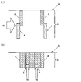
図1(a)は、本発明の地盤中での遮水および透水回復工法における工程<1>を模式的に示した概略図である。上部に示した概略工程断面図のa-a断面を下部に示している。(b)は、工程<2>を模式的に示した概略図である。上部に示した概略工程断面図のb-b断面を下部に示している。 FIG. 1(a) is a schematic diagram schematically showing step <1> in the method for impermeability and restoration of permeability in ground according to the present invention. The lower part shows the aa section of the schematic process cross-sectional view shown in the upper part. (b) is a schematic diagram schematically showing step <2>. The bb cross section of the schematic process cross-sectional view shown in the upper part is shown in the lower part.
図1(a)に示したように、地盤中での遮水および透水回復工法の工程<1>では、施工対象地盤となる地盤Gに遮水処理するにあたり、地盤Gの掘削孔1において、高吸水性ポリマー粒子含有液3を掘削孔1に挿入した注入管2から周囲の地盤中に注入する。これにより、高吸水性ポリマー注入層4を造成することができる。
As shown in FIG. 1(a), in step <1> of the method for impermeability and water permeability restoration in the ground, in order to impermeable the ground G, which is the ground to be constructed, in the
本発明の地盤中での遮水および透水回復工法を適用可能な地盤Gとしては、特に制限されることはなく、例えば、砂質地盤(砂層)、砂礫地盤(砂礫層)などが例示され、特に、地盤Gが砂礫地盤であることが好ましく考慮される。 The ground G to which the ground impermeability and permeability recovery method of the present invention can be applied is not particularly limited. In particular, it is considered preferable that the ground G is gravel ground.
掘削孔1の孔径としては、例えば、φ100mm~φ600mm程度が例示されるが、掘削に用いるシャフトの直径や注入管2の直径に応じて適宜変更することが可能である。また、掘削に用いるシャフト(掘削シャフト)の材質については、例えば、耐食性を備えるステンレス鋼管等が例示される。
The hole diameter of the
注入管2はその側壁面に貫通孔21を複数有しており、注入管2内に送液された高吸水性ポリマー粒子含有液3を、貫通孔21を通じて掘削孔1の孔壁を構成する地盤の土壌骨格における間隙に注入可能とされている。注入管2の貫通孔21は、常時開放状態であってもよいし、開閉自在な蓋によって覆われている態様や、二重構造の筒体を回転させることにより、貫通孔21の開放状態および閉鎖状態とに相互に切り替え可能な態様であってもよい。また、注入管2と掘削孔1との隙間が栓止されていることも考慮される。注入管2と掘削孔1との隙間が栓止されていることにより、掘削孔1内部において高吸水性ポリマー粒子含有液3が逆流することを未然に防止することができる。
The
注入管2の管径としては、例えば、φ100mm程度であることが例示されるが、掘削シャフトの直径などに応じて適宜変更することが可能である。また、注入管2の材質としては、特段限定されることはないが、例えば、耐食性を備えるステンレス鋼管やプラスチック樹脂製の管等を適宜用いることが可能である。
The diameter of the
注入管2は、前記のとおりの掘削シャフトと別体の管であってもよいし、公知のジェットグラウト工法で用いられる注入管のように、掘削シャフトと注入管とが同一の管であってもよい。さらに、注入管2の構造は、公知の薬液注入工法で用いられる、掘削シャフトの内部空間に注入管が配置された二重管構造であってもよい。
The
本発明の地盤中での遮水および透水回復工法では、工程<1>において、高吸水性ポリマー注入層4の形成時に地盤Gの土壌粒子と、高吸水性ポリマー粒子含有液3とを混合、攪拌することはなく、掘削孔1の孔壁を構成する地盤の土壌骨格における間隙に高吸水性ポリマー粒子含有液3を注入し、高吸水性ポリマー注入層4を造成することを特徴としている。
In the method for imperviousness and water permeability restoration in the ground of the present invention, in step <1>, soil particles in the ground G and a liquid 3 containing superabsorbent polymer particles are mixed at the time of forming the superabsorbent
高吸水性ポリマー粒子含有液3は、少なくとも、水と、吸水して膨潤した高吸水性ポリマー粒子とを含有するものである。本発明者らは、これまでに、地盤掘削用高吸水性ポリマー粒子含有液を含む安定組成物及びこれを用いた施工法を提案しており、この提案で使用している高吸水性ポリマー粒子を応用することができる(例えば、特開2013-57061号公報参照)。
The superabsorbent polymer particle-containing
具体的には、前記高吸水性ポリマー粒子は、架橋構造をもつ親水性のポリマーであって、自重の10倍~500倍程度の吸水性を有し、圧力をかけても水分を放出しにくいという特徴を備える。このようなポリマーの吸水作用は、ポリマー内外のイオン濃度差によって生じる浸透圧によって発揮される。そのため、ポリマーと混合攪拌させる溶媒の電気伝導率を、例えば、塩化ナトリウム等の電解質を添加することによって調整可能であり、ポリマーの質量に対する吸水した水の質量比(以下、吸水倍率)を変化させることができる。なお、溶媒としては、例えば、水、特に施工現場においては水道水を好適に用いることができる。 Specifically, the superabsorbent polymer particles are hydrophilic polymers having a crosslinked structure, have a water absorbency of about 10 to 500 times their own weight, and are less likely to release water even when pressure is applied. It has the characteristics of The water absorbing action of such a polymer is exhibited by the osmotic pressure caused by the ion concentration difference between the inside and outside of the polymer. Therefore, the electrical conductivity of the solvent to be mixed and stirred with the polymer can be adjusted, for example, by adding an electrolyte such as sodium chloride, and the mass ratio of absorbed water to the mass of the polymer (hereinafter referred to as water absorption ratio) is changed. be able to. As the solvent, for example, water, especially tap water can be suitably used at construction sites.
吸水後の高吸水性ポリマー粒子の粒径は、吸水前のポリマー粒子の粒径と吸水倍率によって決まり、吸水後の吸水性ポリマー粒子を真球形で水と密度が等しいと近似すると、次式で求められる。 The particle size of superabsorbent polymer particles after water absorption is determined by the particle size and water absorption ratio of the polymer particles before water absorption. Desired.
Da=(Q+1)1/3・Db (1)
(式中、Q:吸水倍率、Da:吸水後のポリマー粒径、Db:吸水前のポリマー粒径、を表している)
ポリマー粒子の質量と吸水倍率の積は、その含有液下でポリマー粒子が吸収できる水の量の最大値を表し、それ以上の水と混合攪拌させた場合、ポリマー粒子に吸収されない余剰の水が生じる。これを自由水と定義し、全水量に対する自由水の割合を自由水率として(2)式で定義する。
D a =(Q+1) 1/ 3 ·D b (1)
(In the formula, Q: water absorption capacity, D a : polymer particle size after water absorption, D b : polymer particle size before water absorption)
The product of the mass of the polymer particles and the water absorption capacity represents the maximum amount of water that the polymer particles can absorb under the liquid contained therein. occur. This is defined as free water, and the ratio of free water to the total amount of water is defined as the free water ratio by equation (2).
自由水率:η(%)=(自由水の質量)/(全水量)×100 (2)
なお、前記高吸水性ポリマー粒子の吸水量は、JIS K 7223で定義づけられており、吸水量の測定方法についても前記JIS K 7223の記載に基づいて行われる。
Free water rate: η (%) = (mass of free water) / (total water volume) x 100 (2)
The amount of water absorption of the superabsorbent polymer particles is defined in JIS K 7223, and the method for measuring the amount of water absorption is also based on the description of JIS K 7223.
前記高吸水性ポリマー粒子の種類は、上記の条件を満足するものであれば特に制限されることなく用いることができ、例えば、デンプン系、セルロース系、合成ポリマー系からなる群より選択される少なくとも1種であることが好ましく考慮される。 The type of superabsorbent polymer particles can be used without particular limitation as long as they satisfy the above conditions. For example, at least one selected from the group consisting of starch, cellulose, and synthetic polymer One type is preferably considered.
上記の高吸水性ポリマー粒子の中でも、合成ポリマー系のポリアクリル酸ナトリウム高吸水性ポリマー粒子は、性能とコストの両面に優れているため、特に好適に用いることができる。 Among the superabsorbent polymer particles described above, synthetic polymer-based sodium polyacrylate superabsorbent polymer particles are excellent in terms of both performance and cost, and thus can be particularly preferably used.
ポリアクリル酸ナトリウム高吸水性ポリマー粒子は、アクリル酸ナトリウム(CH2=CH-COONa)に架橋剤を加えて、軽度に架橋させた3次元網目構造を持ったアクリル酸重合体部分ナトリウム塩架橋物のゲルである。架橋剤としては、従来公知のものを用いることができる。 Sodium polyacrylate superabsorbent polymer particles are sodium acrylate (CH2=CH-COONa) added with a cross-linking agent, and lightly cross-linked acrylic acid polymer partial sodium salt cross-linked product having a three-dimensional network structure. is a gel. A conventionally well-known thing can be used as a crosslinking agent.
前記ポリアクリル酸ナトリウム高吸水性ポリマー粒子は、水を吸収するとカルボキシル基がゲル中にナトリウムイオンを解離し、純水ならば自重の100~1000倍にも達する膨潤度を生み出すことが知られている。 It is known that when the sodium polyacrylate superabsorbent polymer particles absorb water, the carboxyl groups dissociate sodium ions in the gel, and if pure water is used, the degree of swelling reaches 100 to 1000 times its own weight. there is
このようなポリアクリル酸ナトリウム高吸水性ポリマー粒子としては、例えば、GEOSAP(登録商標、以下同様)等が例示される。GEOSAPの場合、吸水倍率が自重の450倍程度であり、高吸水性ポリマー粒子含有液3の流動性が良好で、しかも砂礫層の間隙を確実に目詰めすることできる。 Examples of such sodium polyacrylate superabsorbent polymer particles include GEOSAP (registered trademark, hereinafter the same). In the case of GEOSAP, the water absorption capacity is about 450 times its own weight, the fluidity of the liquid 3 containing superabsorbent polymer particles is good, and the gaps in the gravel layer can be reliably filled.
また、ポリアクリル酸ナトリウム高吸水性ポリマー粒子は、アクリル酸ナトリウムに対して架橋剤を多く配合することで、得られるゲルは硬くなり、その吸水量は減少する。また、架橋剤の配合を少なくすると、得られるゲルは柔らかくなり、その吸水量は増大する。 In addition, by blending a large amount of a cross-linking agent with sodium polyacrylate, the resulting gel becomes hard and its water absorption is reduced. Also, when the amount of the cross-linking agent is reduced, the resulting gel becomes softer and its water absorption increases.
さらに、特殊なポリアクリル酸ナトリウム高吸水性ポリマー粒子として、架橋剤により重合させた高吸水性ポリマー粒子の表面をさらに架橋させた、シェルとコアの二重構造を有するポリアクリル酸ナトリウム高吸水性ポリマー粒子の利用が例示される。 Furthermore, as a special sodium polyacrylate superabsorbent polymer particle, the surface of the superabsorbent polymer particle polymerized with a cross-linking agent is further crosslinked, and the sodium polyacrylate superabsorbent polymer has a double structure of shell and core. The use of polymer particles is exemplified.
このシェルとコアの二重構造を有するポリアクリル酸ナトリウム高吸水性ポリマー粒子においては、外殻であるシェルの厚みが厚いほど硬質なゲルとなり、その吸水量は減少する。一方、シェルの厚みを薄くすると柔らかいゲルとなり、その吸水量は増大する。 In the sodium polyacrylate superabsorbent polymer particles having a double structure of shell and core, the thicker the shell, which is the outer shell, the harder the gel becomes, and the water absorption decreases. On the other hand, if the thickness of the shell is reduced, it becomes a soft gel and its water absorption increases.
また、上記のシェルとコアは、通常、エステル結合により架橋したものであるが、シェルとコアの架橋が耐アルカリ性、耐電解質性に優れたエーテル結合により架橋したものであるポリアクリル酸ナトリウム高吸水性ポリマー粒子も存在する。本発明においては、エーテル結合によりシェルとコアが架橋したポリアクリル酸ナトリウム高吸水性ポリマー粒子を用いることがより好ましい。 The above shell and core are usually crosslinked by ester bonds, but the shell and core are crosslinked by ether bonds that are excellent in alkali resistance and electrolyte resistance Sodium polyacrylate high water absorption There are also polymeric particles. In the present invention, it is more preferable to use sodium polyacrylate superabsorbent polymer particles in which the shell and core are crosslinked by ether bonds.
上記の特性のほか、ポリアクリル酸ナトリウム高吸水性ポリマー粒子におけるナトリウムイオンの解離は、ゲルがおかれるpHや電解質濃度等の条件にも依存するため、使用条件に応じてその他の高吸水性ポリマー粒子を適宜選択して用いることができる。 In addition to the above properties, the dissociation of sodium ions in sodium polyacrylate superabsorbent polymer particles also depends on conditions such as pH and electrolyte concentration where the gel is placed, so other superabsorbent polymers may be used depending on the conditions of use. Particles can be appropriately selected and used.
高吸水性ポリマー粒子含有液3は、地下トンネル工事などの大深度で使用することも想定されており、施工箇所まで加圧して送液される。この場合、高吸水性ポリマー粒子含有液3中の前記高吸水性ポリマー粒子は、高圧下にさらされるため、加圧による水の保持力の低下が少なく、しかもポリマー粒子自体が変形しにくい架橋構造を持った高吸水性ポリマー粒子の選定が必要である。また、透水層G1の間隙を目詰めするために、前記高吸水性ポリマー粒子の膨潤後の粒径は3mm以下で、かつ粒度分布がより良好であることが望ましい。
The superabsorbent polymer particle-containing
なお、地盤Gが砂礫地盤である場合、地盤の土壌骨格間の間隙量が45~50%であることが例示される。 In addition, when the ground G is gravel ground, it is exemplified that the amount of gaps between soil skeletons of the ground is 45 to 50%.
本発明において、前記高吸水性ポリマー粒子として、ポリアクリル酸ナトリウム高吸水性ポリマー粒子を用いる場合は、上記の条件を満足するものであれば、特に制限されることなく用いることができるが、特に、シェルとコアの二重構造を有するポリアクリル酸ナトリウム高吸水性ポリマー粒子を上記の条件に調整したものを好適に用いることができる。 In the present invention, when sodium polyacrylate superabsorbent polymer particles are used as the superabsorbent polymer particles, they can be used without particular limitation as long as they satisfy the above conditions. , sodium polyacrylate superabsorbent polymer particles having a double structure of shell and core adjusted to the above conditions can be preferably used.
また、本発明では、高吸水性ポリマー粒子含有液3が、膨潤度調整剤を含有していることが好ましく考慮される。さらにまた、この膨潤度調整剤は、電解質を含有しており、この電解質が一価の金属塩であることが好ましく考慮される。前記高吸水性ポリマー粒子の膨潤度は、純水中において最大となるが、前記膨潤度調整剤を含有する水溶液中では、膨潤度が低下する。このような高吸水性ポリマー粒子の特性に基づき、あらかじめ高吸水性ポリマー粒子含有液3に膨潤度調整剤を添加することにより、前記高吸水性ポリマー粒子の膨潤を抑制し、粒径を小さく制御することができるとともに、高吸水性ポリマー粒子含有液3の単位体積あたりに含有される前記高吸水性ポリマー粒子の含有量を増大させることができる。これにより、注入管や送液系を詰まらせることなく、施工対象地盤Gまで前記高吸水性ポリマー粒子の含有量の高い高吸水性ポリマー粒子含有液3を送液することが可能となる。そして、施工対象地盤G内において、高吸水性ポリマー粒子含有液3と地下水が接触することにより、高吸水性ポリマー粒子含有液3中の電解質濃度が希釈され、前記高吸水性ポリマー粒子が所期の粒子径に膨潤して土壌粒子間の間隙の目詰め効果を発揮することができるようになる。
In addition, in the present invention, it is preferably considered that the superabsorbent polymer particle-containing
高吸水性ポリマー粒子含有液3に添加することができる膨潤度調整剤としては、環境負荷が小さく、しかも高吸水性ポリマー粒子を劣化させにくい電解質を用いることが好ましく、例えば、塩化ナトリウム、塩化カリウム、水酸化カリウム等の一価の金属塩が好ましく考慮される。環境負荷の面や経済性の面を考慮すると、特に、前記電解質が塩化ナトリウムであることがより好ましい。このような膨潤度調整剤を用いることにより、高吸水性ポリマー粒子の膨潤度を適宜調整することが可能となる。
As the swelling degree adjusting agent that can be added to the superabsorbent polymer particle-containing
高吸水性ポリマー粒子含有液3としては、例えば、前記高吸水性ポリマー粒子を純水により膨潤させた状態で、例えば、比重1.20以下、好ましくは比重0.95~1.20の範囲に調整したものが例示される。
As the superabsorbent polymer particle-containing
また、高吸水性ポリマー粒子含有液3の粘性は、高吸水性ポリマー粒子含有液3中の自由水率(%)に基づいて調整することができる。
Moreover, the viscosity of the superabsorbent polymer particle-containing
また、高吸水性ポリマー粒子含有液3には、掘削孔1の孔壁安定性の向上や、高吸水性ポリマー粒子含有液3の粘性調整を目的として助剤を添加することができる。
Further, an auxiliary agent can be added to the superabsorbent polymer particle-containing
前記助剤としては、例えば、ベントナイト、おが屑、パルプ、ロックウール、繊維などの逸泥防止材または水溶性高分子等が例示される。これらは1種単独または2種以上を併用することができる。 Examples of the auxiliary agent include bentonite, sawdust, pulp, rock wool, and fibers, or water-soluble polymers. These can be used singly or in combination of two or more.
さらに、高吸水性ポリマー粒子含有液3には、酸性物質、塩基性物質および塩類等の電解質が混入した際に、高吸水性ポリマー粒子含有液3の性状および品質の劣化の抑制や回復を可能とするための安定剤を添加することができる。
Furthermore, when the superabsorbent polymer particle-containing
前記安定剤としては、希硫酸、硫酸アルミニウム、水酸化アルミニウム、水酸化マグネシウム、ポリアクリルアミド、ポリビニルアルコール、ポリアクリル酸ナトリウム、ポリエチレンオキシド等が例示される。また、前記安定剤としては、炭酸水素ナトリウム、炭酸水素カルシウム、炭酸水素カリウム、炭酸水素アンモニウムなどの炭酸水素塩が例示される。さらに、前記安定剤としては、炭酸ナトリウム、炭酸カルシウム、炭酸カリウム、炭酸アンモニウムなどの炭酸塩等が例示される。これらは1種単独または2種以上を併用することができる。 Examples of the stabilizer include dilute sulfuric acid, aluminum sulfate, aluminum hydroxide, magnesium hydroxide, polyacrylamide, polyvinyl alcohol, sodium polyacrylate, polyethylene oxide and the like. Examples of the stabilizer include hydrogencarbonates such as sodium hydrogencarbonate, calcium hydrogencarbonate, potassium hydrogencarbonate and ammonium hydrogencarbonate. Furthermore, examples of the stabilizer include carbonates such as sodium carbonate, calcium carbonate, potassium carbonate and ammonium carbonate. These can be used singly or in combination of two or more.
このような組成の高吸水性ポリマー粒子含有液3を掘削孔1内に注入する際には、まず、図1(a)に示したように、施工機を用いて地盤Gに掘削孔1を掘削し、掘削孔1内に注入管2を配管する。そして、注入管2に高吸水性ポリマー粒子含有液3を送液供給し、注入管2の貫通孔21より、流動性を有する状態にある高吸水性ポリマー粒子含有液3を地盤Gの土壌骨格間の間隙に注入する。
When injecting the superabsorbent polymer particle-containing
高吸水性ポリマー粒子含有液3に膨潤度調整剤として一価の金属塩を添加して、前記高吸水性ポリマー粒子の膨潤度を抑制している場合、地盤G内において、高吸水性ポリマー粒子含有液3と地下水Wが接触して、含有液中の電解質濃度が低下するとともに、前記高吸水性ポリマー粒子が自重の100倍以上に膨潤する。膨潤後の前記高吸水性ポリマー粒子の粒子径としては、0.5mm~3mm程度に達する。
When a monovalent metal salt is added as a swelling degree adjusting agent to the superabsorbent polymer particle-containing
このようにして地盤Gに注入された、膨潤度の高い状態の高吸水性ポリマー粒子が、地盤G内の土壌粒子間の間隙に土壌骨格を維持したまま充填される。土壌粒子間の間隙が前記高吸水性ポリマー粒子によって目詰めされた高吸水性ポリマー注入層4を形成し、地盤Gの透水性を低下させることにより、地盤G中における地下水Wの流れを遮水することができる。
The highly swollen superabsorbent polymer particles injected into the ground G in this way fill the gaps between the soil particles in the ground G while maintaining the soil skeleton. By forming a superabsorbent
このように、本発明の地盤中での遮水および透水回復工法では、地盤Gに掘削した掘削孔1に配管した注入管2を介して、注入管2近傍の地盤G中に高吸水性ポリマー粒子含有液3を注入することにより、地盤Gの遮水性を改良するので、施工箇所の上流において薬液を注入する従来の工法と比較して遮水性の改良範囲を小さくすることができる。そのため、従来の工法に比べて、環境負荷が小さく、しかも施工コストを抑制することが可能である。
As described above, in the method of impermeability and water permeability restoration in the ground of the present invention, the superabsorbent polymer By injecting the particle-containing
上記のとおりの工程<1>に続いて、本発明の地盤中へのポリマー注入による遮水および透水回復工法では、高吸水性ポリマー注入層4に分離剤81を注入し、高吸水性ポリマー注入層4中の高吸水性ポリマー粒子が取り込んでいる水分を放出させる。すなわち、分離剤81の注入は、図1(b)に示したように、高吸水性ポリマー注入層4に有孔管8を埋設し、有孔管8に設けられた貫通孔82より高吸水性ポリマー注入層4に注入する方法が例示される。
Following step <1> as described above, in the impermeable and permeable restoration construction method by injecting a polymer into the ground of the present invention, a separating
図1(b)に示したように、分離剤81を注入することにより、土壌粒子間の間隙を目詰めしていた前記高吸水性ポリマー粒子の水を放出させ、地盤G中の透水性を回復させることができる。
As shown in FIG. 1(b), by injecting the separating
分離剤81は、第二の電解質を含有することが好ましく考慮される。ここでいう第二の電解質は、高吸水性ポリマー粒子含有液3に膨潤度調整剤として含まれる第一の電解質とは別異の電解質である。
Separating
高吸水性ポリマー注入層4に分離剤81として第二の電解質を注入すると、高吸水性ポリマー注入層4中の前記高吸水性ポリマー粒子は、電解質の種類およびそれぞれの電解質の電解質濃度に応じて、取り込んでいる水を放出し、その体積を減少させる。
When a second electrolyte is injected as a separating
前記第二の電解質としては、第一の電解質とは別異であり、かつ高吸水性ポリマー注入層4に注入することにより水を放出させることができる電解質であれば特に制限されることなく用いることができる。例えば、水酸化カルシウム等の塩基性物質、塩化カルシウム等の塩類、塩酸、硫酸、硝酸、くえん酸等の酸性物質、およびこれらの酸性物質の塩等が例示される。これらの電解質は1種単独または2種以上を併用することができるが、中でも、前記第二の電解質が水酸化カルシウム、塩化カルシウム等の二価の金属塩であることが、好ましく考慮される。環境負荷の面や経済性の面を考慮すると、特に、前記第二の電解質が塩化カルシウムであることがより好ましい。
The second electrolyte is not particularly limited as long as it is different from the first electrolyte and can release water when injected into the superabsorbent
分離剤81の添加としては、例えば、高吸水性ポリマー粒子含有液3の成分組成が前記高吸水性ポリマー粒子0.2質量%、加重材4.8質量%、水95.0質量%である場合、通常の高吸水性ポリマー粒子含有液の0.2質量%以上、高比重の高吸水性ポリマー粒子含有液の場合0.3~0.4質量%の塩化カルシウムを添加することが例示される。分離剤81の添加量が上記の範囲内であれば、分離剤81により、高吸水性ポリマー粒子含有液3を、加重材および水分を放出した高吸水性ポリマー粒子を含む5質量%の固形物と、95質量%を占める塩化カルシウム水溶液とに分離することができる。なお、ここでいう95質量%は塩化カルシウム水溶液の質量%濃度を意味してはいない。
As for the addition of the separating
上記のメカニズムにより、高吸水性ポリマー注入層4に対して、分離剤81を注入することで、高吸水性ポリマー注入層4中の前記高吸水性ポリマー粒子から水分が放出されて、該高吸水性ポリマー粒子の体積および膨潤度が大きく低下する。そのため、前記高吸水性ポリマー粒子による土壌粒子の間隙の目詰め効果が低下し、地盤G中の透水性が回復する。
By injecting the separating
なお、高吸水性ポリマー粒子含有液3には、環境負荷の大きい重金属元素等は含まれていないため、水分を放出した高吸水性ポリマー粒子を、そのまま地中に放置しておいても、環境を汚染するおそれがほとんどない。また、前記高吸水性ポリマー粒子は、分離剤81と接触することにより、経時的に劣化して、やがては地中で分解される。このように、高吸水性ポリマー粒子含有液3を固形物と液体に分離して廃棄することができる本発明の地盤中へのポリマー注入による遮水および透水回復工法によれば、工事用資材の廃棄が容易になることは勿論、処理コストを非常に安価に抑えることができる。
In addition, since the superabsorbent polymer particle-containing
地盤Gに分離剤81注入用の有孔管82を設置する態様の場合、最後に、地盤Gに設けた掘削孔1から有孔管82を撤去する。有孔管82の撤去後は、掘削孔1の堀屑の土砂等を用いて、掘削孔1を埋め戻すことにより、施工対象である地盤Gの原状回復は完了する。
In the case of the mode in which the
このように、高吸水性ポリマー粒子含有液3を、固形物と液体に分離して原状回復することができる本願発明の地盤中へのポリマー注入による遮水および透水回復工法によれば、環境修復性が優れていることはもちろん、処理コストを非常に安価に抑えることができる。しかも、地盤中へのポリマー注入は、原地盤の骨格・強度を維持したまま行われるので、前記高吸水性ポリマー粒子が水分を放出し、原地盤の土壌骨格における間隙が復元したとしても、施工前と比較して原地盤の強度が低下することはない。
In this way, according to the method of imperviousness and permeation restoration by injecting polymer into the ground of the present invention, which can separate the superabsorbent polymer particle-containing
また、本発明の地盤中での遮水および透水回復工法では、前記<1>の工程の前または後に、高吸水性ポリマー注入層の上部、下部または中間部に山留壁を造成する工程を含むことが好ましく考慮される。 In addition, in the method for impermeability and water permeability recovery in the ground of the present invention, before or after the step <1>, a step of creating an earth retaining wall on the upper, lower or intermediate portion of the superabsorbent polymer injection layer. It is preferably considered to include.
図2(1)(2)(3)(4)は、本発明の地盤中での遮水および透水回復工法の別の実施形態を模式的に示した概略工程断面図である。この実施形態では、高吸水性ポリマー注入層4の構築が完了した後、その上部(地表面からの施工深度Dより上部)に山留壁6を構築する態様を示している。
FIGS. 2(1), (2), (3), and (4) are schematic process cross-sectional views schematically showing another embodiment of the method for impermeability and restoration of permeability in ground according to the present invention. In this embodiment, after the construction of the superabsorbent
このように、高吸水性ポリマー注入層4と山留壁6とを地盤G中に併存させることにより、高吸水性ポリマー注入層4を補強することができ、遮水性に優れるのみならず強度面にも優れた止水構造を地盤G中に構築することが可能となる。
In this way, by coexisting the superabsorbent
図2(1)に示すように、本実施形態では、まず、施工対象地盤となる地盤Gに遮水処理するにあたり、透水層G1および不透水層G2に掘削孔1を掘削した後、この掘削孔1に注入管2を配管し、注入管2を介して透水層G1および不透水層G2の土壌中に高吸水性ポリマー粒子含有液3を注入する。
As shown in FIG. 2(1), in the present embodiment, first, in order to impermeably treat the ground G, which is the ground to be constructed, drill holes 1 are drilled in the permeable layer G 1 and the impermeable layer G 2 , An
透水層G1としては、例えば、砂質地盤(砂層)、砂礫地盤(砂礫層)などが例示され、特に砂礫地盤であることが好ましく考慮される。 Examples of the permeable layer G1 include sandy ground (sand layer), gravel ground (gravel layer), and the like, and gravel ground is particularly preferred.
また、不透水層G2としては、例えば、粘土質地盤(粘土層)などが例示される。 Moreover, as the impermeable layer G2, for example, a clayey ground ( clay layer) is exemplified.
続いて、図2(2)に示したように、高吸水性ポリマー注入層4の構築が完了した後、その上部(地表面からの施工深度Dより上部)に山留壁6を構築する。
Subsequently, as shown in FIG. 2(2), after the construction of the superabsorbent
山留壁6は、従来公知の硬化性の材料を用いて造成することができ、例えば、セメントミルクと掘削土とを混合造成してなるソイルセメント層や、ベントナイト混合土を用いて造成したエコクレイウォールなどが例示される。
The
山留壁6として、ソイルセメント層を構築する際には、掘削土7aにセメントミルク7bを混合する。このようにして、地上まで掘削機5を引上げながらソイルセメント層からなる山留壁6を構築することができる。
When constructing a soil cement layer as the
なお、高吸水性ポリマー注入層4と山留壁6は、それぞれの上端面および下端面が直接接触するように施工してもよいし、高吸水性ポリマー注入層4と山留壁6との間に中間層を設けてもよい。
The superabsorbent
さらに、山留壁6の強度を補強するために、図2(3)に示すように、山留壁6の中に芯材71を挿入する態様も例示される。
Furthermore, in order to reinforce the strength of the
そして、本実施形態では、前記遮水構造を構築し、地下構造物などを施工した後、高吸水性ポリマー注入層4に分離剤81を注入し、高吸水性ポリマー注入層4中の高吸水性ポリマー粒子が取り込んでいる水分を放出させる。すなわち、図2(4)に示したように、分離剤81を注入することにより、土壌粒子間の間隙を目詰めしていた前記高吸水性ポリマー粒子の水を放出させ、地盤G中の施工深度Dより下方の透水層G1における透水性を回復させることができる。原地盤G0における土壌骨格が維持されているので、土壌粒子間の間隙を目詰めしていた前記高吸水性ポリマー粒子の水を放出させた後であっても、原地盤G0の強度は維持されている。
Then, in the present embodiment, after constructing the impermeable structure and constructing underground structures and the like, the separating
分離剤81の注入方法は、特に制限されることはなく、例えば、図2(4)に示したように、高吸水性ポリマー注入層4の近傍、特に、地下水流の上流側に有孔管8を埋設し、有孔管8に設けられた貫通孔82より高吸水性ポリマー注入層4に注入する態様等が例示される。
The method of injecting the separating
図3(a)(b)は、本発明の地盤中での遮水および透水回復工法におけるさらに別の実施形態を模式的に示した概略工程断面図である。 FIGS. 3(a) and 3(b) are schematic process cross-sectional views schematically showing still another embodiment of the method for impermeability and restoration of permeability in ground according to the present invention.
図3(a)の態様では、高吸水性ポリマー注入層4の同一軸線上に山留壁6を構築するのではなく、高吸水性ポリマー注入層4の上端部と山留壁6の下端部とが一部重なり合うように隣接する態様である。
In the embodiment of FIG. 3( a ), the retaining
図3(b)の態様では、ソイルセメント連続壁などの山留壁6の一部に、あらかじめ他の部分と比較して、その全長の短い箇所を設け、該全長の短い山留壁6の下方に高吸水性ポリマー注入層4を造成する態様である。高吸水性ポリマー注入層4が健在である場合、図中に破線矢印で示した、手前側から奥行方向に向かう地下水Wの流れを遮水可能であり、分離剤81の注入後、地盤Gの透水性を回復した場合、山留壁6の前記全長の短い箇所を地下水Wが流下できるようになる。
In the embodiment shown in FIG. 3(b), a portion of the
以下に、実施例を示すが、本発明の地盤中での遮水および透水回復工法は、実施例により何ら制限されることはない。 Examples are shown below, but the method for impermeability and water permeability restoration in the ground of the present invention is not limited by the examples.
<1.高吸水性ポリマー粒子含有液の基礎実験>
本発明の地盤中での遮水および透水回復工法に用いられる高吸水性ポリマー粒子含有液については、基礎実験から以下のとおりの性質が確認されている。
<1. Basic Experiment of Liquid Containing Super Absorbent Polymer Particles>
Basic experiments have confirmed the following properties of the liquid containing superabsorbent polymer particles used in the ground impermeability and permeability recovery method of the present invention.
(1)高吸水性ポリマー粒子含有液の電気伝導率と吸水倍率の関係
図4に示したように、高吸水性ポリマー粒子含有液の電気伝導率xと吸水倍率の逆数yとの間には、以下の関係式が成立する。
(1) Relationship between electrical conductivity and water absorption capacity of liquid containing superabsorbent polymer particles As shown in FIG. , the following relational expression holds.
y=3×10⁻⁶x+0.0016 (3)
ここで、x:高吸水性ポリマー粒子含有液の電気伝導率(μS/cm)
y:吸水倍率の逆数(1/倍)
上記の式(3)より、高吸水性ポリマー粒子含有液の電気伝導率を調整することにより、高吸水性ポリマー粒子の吸水率をコントロール可能であることが確認された。
y=3×10 −6 x+0.0016 (3)
Here, x: the electrical conductivity of the liquid containing the superabsorbent polymer particles (μS/cm)
y: reciprocal of water absorption ratio (1/fold)
From the above formula (3), it was confirmed that the water absorption rate of the superabsorbent polymer particles can be controlled by adjusting the electrical conductivity of the superabsorbent polymer particle-containing liquid.
(2)膨潤度調整剤の電解質濃度と電気伝導率の関係
膨潤度調整剤として、塩化ナトリウムNaClを用いた場合、NaCl濃度(質量%濃度)と電気伝導率の関係は、図5に示したように、ほぼ比例関係にある。NaCl濃度(質量%濃度)xと高吸水性ポリマー粒子含有液の電気伝導率yとの間には、以下の関係式が成立する。
(2) Relationship between electrolyte concentration and electrical conductivity of swelling degree modifier When sodium chloride NaCl is used as the swelling degree modifier, the relationship between NaCl concentration (mass% concentration) and electrical conductivity is shown in FIG. As such, there is an almost proportional relationship. The following relational expression holds between the NaCl concentration (mass % concentration) x and the electrical conductivity y of the superabsorbent polymer particle-containing liquid.
y=1.75×10⁴x+43.8 (4)
ここで、x:NaCl濃度(質量%濃度)
y:高吸水性ポリマー粒子含有液の電気伝導率(μS/cm)
上記の式(4)より、NaClの添加量を調整することにより、高吸水性ポリマー粒子の電気伝導率をコントロール可能であることが確認された。
y=1.75×10 4 x+43.8 (4)
Here, x: NaCl concentration (mass% concentration)
y: electrical conductivity of liquid containing superabsorbent polymer particles (μS/cm)
From the above formula (4), it was confirmed that the electrical conductivity of the superabsorbent polymer particles can be controlled by adjusting the amount of NaCl added.
上記(3)(4)の結果より、高吸水性ポリマー粒子にあらかじめ吸水させる使用水または高吸水性ポリマー粒子含有液の電気伝導率を調整し、高吸水性ポリマー粒子含有液の自由水率を調整すれば、所定の吸水余力を残した高吸水性ポリマー粒子を、圧送機機械に応じた粘性(流動性)に調整して圧送することが可能となる。 From the results of (3) and (4) above, the electrical conductivity of the water used to pre-absorb water into the superabsorbent polymer particles or the liquid containing superabsorbent polymer particles is adjusted to increase the free water content of the liquid containing superabsorbent polymer particles. By adjusting, it becomes possible to adjust the viscosity (fluidity) according to the pumping machine and pump the superabsorbent polymer particles with a predetermined residual water absorption capacity.
<2.一次元模型地盤での遮水層の形成試験と透水回復試験>
遮水層の形成に関して、高吸水性ポリマー粒子含有液により掘削孔の壁面の周囲に遮水層ができることを以下の実験で確認した。
<2. Impermeable Layer Formation Test and Permeability Recovery Test on One-Dimensional Model Ground>
With regard to the formation of the impermeable layer, it was confirmed in the following experiments that the liquid containing the superabsorbent polymer particles forms the impermeable layer around the wall surface of the borehole.
図6は、不透水層形成を計測する装置の概略図である。図6において、模擬地盤11は、厚さ200mmとし、砂層から砂礫地盤を想定し、試料土として2種類の珪砂(粒度が中粒の東北珪砂4号)を使用した。また、高吸水性ポリマー粒子(ポリアクリル酸ナトリウム:商品名GEOSAP、三洋化成工業社製)として、粒度の異なる2種類(乾燥状態で粗粒:粒径150~710μm、細粒:20~50μm)を使用した。
FIG. 6 is a schematic diagram of an apparatus for measuring impermeable layer formation. In FIG. 6, the
まず、地盤中における遮水層の形成性を確認するために、第1のシリンダー13、第2のシリンダー14にコンプレッサー9により、300kN/m2の拘束圧を加え、さらに第1のシリンダー13には圧力水頭として20kN/m2を加え、合計320kN/m2をコンプレッサー9により加えた。模擬地盤11中に浸透した浸透水10は、第1のシリンダー13と第2のシリンダー14とを連通する連通路を介して、第2のシリンダー14内部へと移動する。このようにして、第2のシリンダー14内部へと移動し、貯留された浸透水10の質量を電子はかり12で秤量し、貯留された浸透水10の質量を基に透水係数を算出した。
First, in order to confirm the formation of the impermeable layer in the ground, a confining pressure of 300 kN/m 2 was applied to the
透水試験の結果、東北珪砂4号の透水係数は2.0~4.75×10⁻²cm/sであるが、高吸水性ポリマー粒子含有液を珪砂に浸透させると、透水係数は1.83×10-8cm/sと小さくなり、遮水層が形成されることを確認した。 As a result of the water permeability test, the permeability coefficient of Tohoku Silica Sand No. 4 is 2.0 to 4.75×10 −2 cm/s. It was as small as 83×10 −8 cm/s, confirming the formation of a waterproof layer.
次に、模擬地盤11に浸透水10として、塩化カルシウムCaCl2 1質量%溶液を浸透させると、模擬地盤11の透水係数は2.67×10⁻⁴cm/sと大きくなり、本来の珪砂の透水係数の範囲内となる。このことは、高吸水性ポリマー粒子が塩化カルシウムCaCl2の作用により水を放出し、体積が減少することにより、土壌骨格の間隙を目詰めすることができなくなり、水を通過させたことを示している。
Next, when a 1% by mass solution of calcium chloride CaCl 2 is permeated into the
<3.二次元模型地盤での遮水層の形成試験と透水回復試験>
上記2.の一次元注入実験の結果を踏まえ、より実地盤に近い条件および実施工に近い方法で地盤の物性や遮水性を確認することを目的として、二次元模型地盤での不透水層の形成試験と透水回復試験を行った。
<3. Impermeable layer formation test and permeability recovery test on two-dimensional model ground>
2. above. Based on the results of the one-dimensional injection experiment, the formation test of the impermeable layer on the two-dimensional model ground and the A water permeability recovery test was performed.
図7に、実験装置である二次元土槽(土槽内径90cm、高さ10cm)および二次元模型地盤の概略断面図を示す。 FIG. 7 shows a schematic cross-sectional view of a two-dimensional soil tank (inner diameter of the soil tank of 90 cm, height of 10 cm) and a two-dimensional model ground, which are experimental devices.
まず、二次元土槽内で6cmの水深を保ち、水面より20cmの高さから試料砂を落下させる水中落下法により二次元模型地盤を作製した。余盛り高さを3cmとし、余剰分の砂試料は除去した。 First, a two-dimensional model ground was prepared by an underwater drop method in which a water depth of 6 cm was maintained in a two-dimensional soil tank and sample sand was dropped from a height of 20 cm above the water surface. The height of the surplus was set to 3 cm, and the surplus sand sample was removed.
このようにして作製した二次元模型地盤の上面に蓋をして、間隙水圧10kPaを付与し、さらに、図8に示したように、上載圧として320kPaを徐々に載荷し、二次元模型地盤を圧密した。 The upper surface of the two-dimensional model ground prepared in this manner was covered, and a pore water pressure of 10 kPa was applied. compacted.
圧密終了後、図8に示したように、注入パイプ内の水を高吸水性ポリマー粒子含有液で置換し、有効注入圧300kPaで注入水槽より高吸水性ポリマー粒子含有液を圧送し、注入に伴い押し出された間隙水を排水槽へ排出させた。なお、高吸水性ポリマー粒子としては、GEOSAPを用い、一次元注入実験において良好な注入性が得られた配合で調製し、注入域を視覚化するため、食紅で着色して高吸水性ポリマー粒子含有液を調製した。 After the consolidation, as shown in FIG. 8, the water in the injection pipe was replaced with the liquid containing superabsorbent polymer particles, and the liquid containing superabsorbent polymer particles was pumped from the injection tank at an effective injection pressure of 300 kPa. The interstitial water that was pushed out was discharged into the drainage tank. As the superabsorbent polymer particles, GEOSAP was used and prepared with a formulation that gave good injectability in a one-dimensional injection experiment. A containing liquid was prepared.
高吸水性ポリマー粒子含有液の注入量の収束を確認した後、二次元土槽を解体し、注入量の推定および注入径の実測を行った。また、二次元模型地盤上面の貫入抵抗測定および注入域からサンプリングを行い、透水試験を行った。 After confirming the convergence of the injection amount of the liquid containing superabsorbent polymer particles, the two-dimensional soil tank was dismantled, and the injection amount was estimated and the injection diameter was measured. In addition, penetration resistance was measured on the upper surface of the two-dimensional model ground, and sampling was performed from the injection area to conduct a permeability test.
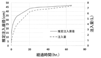
[ポリマー注入量の推定]
注入時間(経過時間)と注入量の関係を図9に示す。図9より、約65時間で直径47cm程度まで高吸水性ポリマー粒子含有液が注入されたと推定された。なお、図9中には、推定注入直径として二次元模型地盤の間隙が高吸水性ポリマー粒子含有液により充填されているとものとして注入量から算出した数値も示している。
[Estimation of Polymer Injection Amount]
FIG. 9 shows the relationship between injection time (elapsed time) and injection amount. From FIG. 9, it was presumed that the superabsorbent polymer particle-containing liquid was injected to a diameter of about 47 cm in about 65 hours. In addition, FIG. 9 also shows numerical values calculated from the injection amount assuming that the gaps in the two-dimensional model ground are filled with the superabsorbent polymer particle-containing liquid as the estimated injection diameter.
図10(a)(b)は、注入終了後の二次元模型地盤を示した写真である。注入径を図10(a)に示した上面で実測すると平均45cm程度であった。上記の推定注入直径の数値と実測値とは極めて近いことを確認できた。 FIGS. 10(a) and 10(b) are photographs showing the two-dimensional model ground after completion of pouring. When the injection diameter was actually measured on the upper surface shown in FIG. 10(a), it was about 45 cm on average. It was confirmed that the values of the above estimated injection diameters and the measured values are very close.
[硬度測定]
二次元模型地盤上面の貫入抵抗測定は、山中式土壌硬度計を用いて行った。
[Hardness measurement]
The penetration resistance of the top surface of the two-dimensional model ground was measured using a Yamanaka soil hardness tester.
二次元模型地盤上面の貫入抵抗分布を図11に示した。測定位置は、図10(a)中のNo.6とNo.12とを結んだ直線上である。なお、中心部は注入パイプが存在するため計測しなかった。 Fig. 11 shows the penetration resistance distribution on the top surface of the two-dimensional model ground. The measurement position is No. in FIG. 10(a). 6 and No. It is on the straight line connecting 12. Note that the central portion was not measured due to the existence of the injection pipe.
図11に示したように、注入パイプ近傍の高吸水性ポリマー粒子含有液注入域では未注入域よりも貫入抵抗が1.5~2倍程度高いことが確認された。この結果から、高吸水性ポリマー粒子含有液注入域において高吸水性ポリマー粒子が充填されていると考えられる。 As shown in FIG. 11, it was confirmed that the penetration resistance was about 1.5 to 2 times higher in the region near the injection pipe where the liquid containing superabsorbent polymer particles was injected than in the non-injected region. From this result, it is considered that superabsorbent polymer particles are filled in the liquid injection region containing superabsorbent polymer particles.
[透水試験]
二次元模型地盤における高吸水性ポリマー粒子含有液注入域から、図12に示したように、注入域の内側部分で2箇所(供試体No.1および2)、注入域の外側部分で2箇所(供試体No.3および4)サンプルを採取し、定水位三軸透水試験に供した。試験条件は、拘束圧310kPa、背圧0kPa、水頭差は圧力換算で100kPaであった。
[Permeability test]
From the superabsorbent polymer particle-containing liquid injection area in the two-dimensional model ground, as shown in FIG. (Specimen Nos. 3 and 4) Samples were collected and subjected to a constant water level triaxial permeability test. The test conditions were a confining pressure of 310 kPa, a back pressure of 0 kPa, and a water head difference of 100 kPa in terms of pressure.
結果を表1に示す。 Table 1 shows the results.

表1に示したように、注入域の内側部分と外側部分のいずれにおいても、3.60×10⁻⁹~8.98×10⁻⁹(cm/s)とほぼ同等の透水係数が得られ、注入域全域において十分な遮水性を得られることが確認された。 As shown in Table 1, almost the same hydraulic conductivity of 3.60 × 10 -9 to 8.98 × 10 -9 (cm/s) was obtained both in the inner part and the outer part of the injection zone. , it was confirmed that sufficient imperviousness can be obtained in the entire injection area.
D 施工深度
G 地盤
G0 地表面
G1 透水層
G2 不透水層
G3 原地盤
W 地下水
1 掘削孔
2 注入管
21 貫通孔
3 高吸水性ポリマー粒子含有液
4 高吸水性ポリマー注入層
5 施工機
6 山留壁
7 混合土
7a 掘削土
7b セメントミルク
71 芯材
8 有孔管
81 分離剤
82 貫通孔
9 コンプレッサー
10 浸透水
11 模擬地盤
12 電子はかり
13 第1のシリンダー
14 第2のシリンダー
D construction depth G ground G0 ground surface G1 permeable layer G2 impermeable layer G3 original ground W groundwater 1 drilling hole 2 injection pipe 21 through hole 3 liquid containing super
Claims (4)
<1>地盤の掘削孔において、一価の金属塩からなる膨潤度調整剤を含む、比重が0.95~1.20の範囲の高吸水性ポリマー粒子含有液を前記掘削孔に挿入した注入管から周囲の地盤中に注入し、高吸水性ポリマー注入層を造成して遮水する工程;
<2>前記高吸水性ポリマー注入層中に、二価以上の多価金属塩からなる分離剤を、高吸水性ポリマー粒子含有液100質量%に対して0.2~0.4質量%の範囲で注入し、前記高吸水性ポリマー粒子が取り込んでいる水分を放出させ透水回復する工程。 A method for impermeability and restoration of permeability in the ground, characterized by including at least the following steps <1> and <2>.
<1> Injection of a liquid containing superabsorbent polymer particles having a specific gravity in the range of 0.95 to 1.20 and containing a swelling degree adjusting agent made of a monovalent metal salt inserted into the drilled hole in the ground. A step of injecting into the surrounding ground from the pipe to form a superabsorbent polymer injection layer to impermeable water;
<2> In the superabsorbent polymer injection layer, 0.2 to 0.4% by mass of a separating agent composed of a polyvalent metal salt having a valence of 2 or more is added to 100% by mass of the superabsorbent polymer particle-containing liquid. A step of injecting water in a range to release the water taken in by the superabsorbent polymer particles to recover the water permeability.
Priority Applications (1)
| Application Number | Priority Date | Filing Date | Title |
|---|---|---|---|
| JP2018088703A JP7112242B2 (en) | 2018-05-02 | 2018-05-02 | Impermeability and Permeability Restoration Method in the Ground |
Applications Claiming Priority (1)
| Application Number | Priority Date | Filing Date | Title |
|---|---|---|---|
| JP2018088703A JP7112242B2 (en) | 2018-05-02 | 2018-05-02 | Impermeability and Permeability Restoration Method in the Ground |
Publications (2)
| Publication Number | Publication Date |
|---|---|
| JP2019194408A JP2019194408A (en) | 2019-11-07 |
| JP7112242B2 true JP7112242B2 (en) | 2022-08-03 |
Family
ID=68468998
Family Applications (1)
| Application Number | Title | Priority Date | Filing Date |
|---|---|---|---|
| JP2018088703A Active JP7112242B2 (en) | 2018-05-02 | 2018-05-02 | Impermeability and Permeability Restoration Method in the Ground |
Country Status (1)
| Country | Link |
|---|---|
| JP (1) | JP7112242B2 (en) |
Citations (5)
| Publication number | Priority date | Publication date | Assignee | Title |
|---|---|---|---|---|
| US20040182577A1 (en) | 2003-03-21 | 2004-09-23 | Jiten Chatterji | Well completion spacer fluids containing fibers and methods |
| JP2013057061A (en) | 2011-08-17 | 2013-03-28 | Waseda Univ | Stable liquid composition of swollen superabsorbent polymer for ground excavation and construction method using the same |
| JP2013224572A (en) | 2012-03-22 | 2013-10-31 | Waseda Univ | Earth retaining wall construction method and earth retaining wall constructed by the same |
| JP2014156546A (en) | 2013-02-15 | 2014-08-28 | Waseda Univ | Swellable high-water-absorption polymer stabilizing liquid composition for shielding method and execution method using the same |
| JP2015063669A (en) | 2013-08-27 | 2015-04-09 | 有限会社マグマ | Composition for foundation digging/pouring material, foundation digging/pouring material, and operation method using the same |
Family Cites Families (3)
| Publication number | Priority date | Publication date | Assignee | Title |
|---|---|---|---|---|
| JPS58189415A (en) * | 1982-04-28 | 1983-11-05 | Kajima Corp | Construction of cut-off wall |
| JPH01142119A (en) * | 1987-11-26 | 1989-06-05 | Dai Ichi Kogyo Seiyaku Co Ltd | Temporary water stopping work |
| JP2819902B2 (en) * | 1991-11-22 | 1998-11-05 | 株式会社大林組 | Liquefaction prevention structure in foundation ground |
-
2018
- 2018-05-02 JP JP2018088703A patent/JP7112242B2/en active Active
Patent Citations (5)
| Publication number | Priority date | Publication date | Assignee | Title |
|---|---|---|---|---|
| US20040182577A1 (en) | 2003-03-21 | 2004-09-23 | Jiten Chatterji | Well completion spacer fluids containing fibers and methods |
| JP2013057061A (en) | 2011-08-17 | 2013-03-28 | Waseda Univ | Stable liquid composition of swollen superabsorbent polymer for ground excavation and construction method using the same |
| JP2013224572A (en) | 2012-03-22 | 2013-10-31 | Waseda Univ | Earth retaining wall construction method and earth retaining wall constructed by the same |
| JP2014156546A (en) | 2013-02-15 | 2014-08-28 | Waseda Univ | Swellable high-water-absorption polymer stabilizing liquid composition for shielding method and execution method using the same |
| JP2015063669A (en) | 2013-08-27 | 2015-04-09 | 有限会社マグマ | Composition for foundation digging/pouring material, foundation digging/pouring material, and operation method using the same |
Also Published As
| Publication number | Publication date |
|---|---|
| JP2019194408A (en) | 2019-11-07 |
Similar Documents
| Publication | Publication Date | Title |
|---|---|---|
| CN101302757B (en) | Method for quickly processing heavy layer soft soil foundation | |
| CN106192974B (en) | A kind of device and method of sludge solidification processing | |
| Huang et al. | Use of self-hardening slurry for trench cutoff wall: A review | |
| CN106866056B (en) | A kind of mud and preparation method thereof for construction of diaphragm wall | |
| Norris et al. | Modified bentonites for soil-bentonite cutoff wall applications with hard mix water | |
| JP2013057061A (en) | Stable liquid composition of swollen superabsorbent polymer for ground excavation and construction method using the same | |
| CN102199925A (en) | Particle antiseepage material for seawater | |
| Karimi | A study of geotechnical applications of biopolymer treated soils with an emphasis on silt | |
| JP7112242B2 (en) | Impermeability and Permeability Restoration Method in the Ground | |
| JP6925834B2 (en) | Ground freezing method | |
| CN101187209A (en) | Discarded pipe harmless filling technology | |
| Shen et al. | Improvement efficacy of RJP method in Shanghai soft deposit | |
| JP6066757B2 (en) | Construction method of permeable foundation | |
| CN106592545B (en) | A kind of drainage system for watery side slope | |
| Jefferis et al. | Polymer systems for fluid supported excavations | |
| JP6141660B2 (en) | Mountain wall construction method and mountain wall constructed by this mountain wall construction method | |
| CN206438495U (en) | Sand filling bag composite pile system is consolidated from after draining | |
| Min et al. | Test study on airtight capability of filter cakes for slurry shield and its application in a case | |
| JP2001207436A (en) | Slurry composition | |
| Merritt et al. | Soil conditioning for EPB tunnelling in coarse grained soils based on laboratory model tests | |
| CN110627435B (en) | Seepage-proofing material for filling horizontal directional drilling and seepage-proofing construction method | |
| CN116837868A (en) | Ecological plant and chemical improvement combined expansive soil slope reinforcement structure | |
| Lashkar-Ara et al. | Impact of Sodium Carbonate on Seepage Reduction in Farm Irrigation Ponds | |
| JP2023125140A (en) | Excavator for soil cement underground continuous wall, and construction method using the same | |
| Shang et al. | Vacuum consolidation of soda-ash tailings |
Legal Events
| Date | Code | Title | Description |
|---|---|---|---|
| A80 | Written request to apply exceptions to lack of novelty of invention |
Free format text: JAPANESE INTERMEDIATE CODE: A80 Effective date: 20180521 |
|
| A621 | Written request for application examination |
Free format text: JAPANESE INTERMEDIATE CODE: A621 Effective date: 20210301 |
|
| A977 | Report on retrieval |
Free format text: JAPANESE INTERMEDIATE CODE: A971007 Effective date: 20211228 |
|
| A131 | Notification of reasons for refusal |
Free format text: JAPANESE INTERMEDIATE CODE: A131 Effective date: 20220105 |
|
| RD02 | Notification of acceptance of power of attorney |
Free format text: JAPANESE INTERMEDIATE CODE: A7422 Effective date: 20220216 |
|
| A521 | Request for written amendment filed |
Free format text: JAPANESE INTERMEDIATE CODE: A523 Effective date: 20220303 |
|
| A521 | Request for written amendment filed |
Free format text: JAPANESE INTERMEDIATE CODE: A821 Effective date: 20220217 |
|
| A521 | Request for written amendment filed |
Free format text: JAPANESE INTERMEDIATE CODE: A523 Effective date: 20220323 |
|
| TRDD | Decision of grant or rejection written | ||
| A01 | Written decision to grant a patent or to grant a registration (utility model) |
Free format text: JAPANESE INTERMEDIATE CODE: A01 Effective date: 20220712 |
|
| A61 | First payment of annual fees (during grant procedure) |
Free format text: JAPANESE INTERMEDIATE CODE: A61 Effective date: 20220722 |
|
| R150 | Certificate of patent or registration of utility model |
Ref document number: 7112242 Country of ref document: JP Free format text: JAPANESE INTERMEDIATE CODE: R150 |