JP7107856B2 - Foreign matter removal device, foreign matter removal catheter, and foreign matter recovery system - Google Patents
Foreign matter removal device, foreign matter removal catheter, and foreign matter recovery system Download PDFInfo
- Publication number
- JP7107856B2 JP7107856B2 JP2018567532A JP2018567532A JP7107856B2 JP 7107856 B2 JP7107856 B2 JP 7107856B2 JP 2018567532 A JP2018567532 A JP 2018567532A JP 2018567532 A JP2018567532 A JP 2018567532A JP 7107856 B2 JP7107856 B2 JP 7107856B2
- Authority
- JP
- Japan
- Prior art keywords
- retriever
- foreign
- catheter
- foreign body
- foreign matter
- Prior art date
- Legal status (The legal status is an assumption and is not a legal conclusion. Google has not performed a legal analysis and makes no representation as to the accuracy of the status listed.)
- Active
Links
Images


Classifications
-
- A—HUMAN NECESSITIES
- A61—MEDICAL OR VETERINARY SCIENCE; HYGIENE
- A61B—DIAGNOSIS; SURGERY; IDENTIFICATION
- A61B17/00—Surgical instruments, devices or methods, e.g. tourniquets
- A61B17/22—Implements for squeezing-off ulcers or the like on the inside of inner organs of the body; Implements for scraping-out cavities of body organs, e.g. bones; Calculus removers; Calculus smashing apparatus; Apparatus for removing obstructions in blood vessels, not otherwise provided for
- A61B17/221—Gripping devices in the form of loops or baskets for gripping calculi or similar types of obstructions
- A61B2017/2212—Gripping devices in the form of loops or baskets for gripping calculi or similar types of obstructions having a closed distal end, e.g. a loop
-
- A—HUMAN NECESSITIES
- A61—MEDICAL OR VETERINARY SCIENCE; HYGIENE
- A61B—DIAGNOSIS; SURGERY; IDENTIFICATION
- A61B90/00—Instruments, implements or accessories specially adapted for surgery or diagnosis and not covered by any of the groups A61B1/00 - A61B50/00, e.g. for luxation treatment or for protecting wound edges
- A61B90/08—Accessories or related features not otherwise provided for
- A61B2090/0801—Prevention of accidental cutting or pricking
- A61B2090/08021—Prevention of accidental cutting or pricking of the patient or his organs
Description
本発明は、異物除去デバイス、異物除去用カテーテル及び異物回収システムに関し、より詳細には、血管などの管状組織の内部に発生した血栓又は塞栓などの異物を除去又は回収する異物除去デバイス、異物除去用カテーテル及び異物回収システムに関する。 TECHNICAL FIELD The present invention relates to a foreign matter removal device, a foreign matter removal catheter, and a foreign matter recovery system, and more particularly, to a foreign matter removal device and foreign matter removal device for removing or recovering a foreign matter such as a thrombus or an embolus generated inside a tubular tissue such as a blood vessel. catheter and foreign body retrieval system.
血管壁から血栓を除去するための血栓除去デバイスとして、図15に示すように、径方向に拡張可能なケージ922を備える血栓除去デバイス900が知られている(例えば、特許文献1参照)。ケージ922は、近位アーム及び遠位アームと呼ばれる管状部材(図示せず。)の先端位置に配設されており、近位アーム及び遠位アームを軸方向に沿って相対的に移動させることにより、ケージ922の径方向の長さを調節可能に構成されている。また、ケージ922にはフラットワイヤ924が取り付けられており、フラットワイヤ924によって血管壁から血栓を掻き取ることができる。
As a thrombus removal device for removing a thrombus from a blood vessel wall, a
しかしながら、上記特許文献1に開示された血栓除去デバイスにおいては、フラットワイヤ924の屈曲部位924Fがケージ922の外側に大きく飛び出しているため、ケージ922を拡張させた状態でケージ922を回転させたり、血管内でケージ922を前進又は後退させたりしたときに、フラットワイヤ924の屈曲部位924Fが血管壁に引っ掛かってしまい、血管壁を損傷させてしまうリスクがある。
However, in the thrombus removal device disclosed in
このような課題は、血管以外の管状組織(例えば、消化管、胆管等)の内部に発生した異物を除去する異物除去デバイスにおいても生じ得るものである。 Such a problem may also occur in a foreign body removal device that removes a foreign body generated inside a tubular tissue other than a blood vessel (eg, digestive tract, bile duct, etc.).
本発明は、前述した課題に鑑みてなされたものであり、その目的は、管状組織を損傷するリスクを低減しつつ、管状組織の内部に発生した異物を除去又は回収することが可能な異物除去デバイス、異物除去用カテーテル及び異物回収システムを提供することにある。 The present invention has been made in view of the problems described above, and an object of the present invention is to reduce the risk of damaging the tubular tissue while removing or recovering the foreign matter generated inside the tubular tissue. It is an object of the present invention to provide a device, a foreign body removal catheter, and a foreign body retrieval system.
本発明の上記目的は、下記の構成により達成される。
体内内腔の異物を除去するための異物除去デバイスであって、
管状部材と、
前記管状部材の一部に配置され、所定の形状に拡張及び収縮可能に構成されたリトリバーとを備え、
前記リトリバーは、
前記管状部材の管軸を中心として配置され、当該リトリバーの拡張及び収縮に応じて前記管軸に直交する径方向に変形可能な複数の主線材と、
隣り合う前記主線材同士をそれぞれ繋ぐ複数の補助線材とを有し、
前記複数の補助線材のそれぞれは、前記リトリバーの軸方向において、前記複数の主線材の対応する主線材の中央部に接続され、
前記複数の補助線材のそれぞれは、隣り合う前記主線材の間において少なくとも1箇所で屈曲可能に構成されており、
前記補助線材の屈曲部位に接続され、前記リトリバーを拡張させたときに前記屈曲部位が前記複数の主線材の前記径方向外側の端部よりも前記管軸側に位置するよう、前記屈曲部位の位置を規制する複数の規制部を、さらに有する、異物除去デバイス。
また、体内内腔の異物を除去するための異物除去用カテーテルであって、カテーテル本体と、前記カテーテル本体の遠位部に配置された、上記の異物除去デバイスと、前記カテーテル本体の近位部に配置され、前記異物除去デバイスにおけるリトリバーの拡張及び収縮を操作する操作部とを備える、異物除去用カテーテル。
また、体内内腔の異物を回収するための異物回収システムであって、上記の異物除去用カテーテルと、体内内腔の異物を捕捉するための異物捕捉用カテーテルとを備え、前記異物捕捉用カテーテルは、前記異物除去用カテーテルを通すルーメンを有する、異物回収システム。
The above objects of the present invention are achieved by the following configurations.
A foreign body removal device for removing a foreign body in a body lumen, comprising:
a tubular member;
A retriever arranged in a part of the tubular member and configured to be expandable and contractible to a predetermined shape,
The retriever is
a plurality of main wires arranged around a tube axis of the tubular member and deformable in a radial direction perpendicular to the tube axis in response to expansion and contraction of the retriever;
and a plurality of auxiliary wires connecting the adjacent main wires,
Each of the plurality of auxiliary wires is connected to a central portion of the corresponding main wire of the plurality of main wires in the axial direction of the retriever,
each of the plurality of auxiliary wires is configured to be bendable at at least one location between the adjacent main wires;
connected to the bent portion of the auxiliary wire, and the bent portion is positioned closer to the tube axis than the radially outer ends of the plurality of main wires when the retriever is expanded. A foreign matter removing device further comprising a plurality of regulating portions that regulate positions .
Also, a foreign body removal catheter for removing a foreign body in a body lumen, comprising: a catheter body; the above foreign body removal device disposed at a distal portion of the catheter body; and a proximal portion of the catheter body. and an operating portion for operating expansion and contraction of a retriever in the foreign body removal device.
Further, a foreign body retrieval system for retrieving a foreign body in a body lumen includes the foreign body removal catheter described above and a foreign body capture catheter for capturing the foreign body in the body lumen, is a foreign body retrieval system having a lumen through which said foreign body removal catheter passes.
本発明の異物除去デバイスによれば、リトリバーを拡張させた状態でリトリバーを回転させたり、管状組織内でリトリバーを前進又は後退させたりしたとしても、補助線材の屈曲部位が管状組織に引っ掛かりにくくなる。その結果、管状組織を損傷するリスクを低減しつつ、管状組織の内部に発生した異物を除去又は回収することが可能となる。 According to the foreign object removal device of the present invention , even if the retriever is rotated in an expanded state or the retriever is moved forward or backward within the tubular tissue, the bent portion of the auxiliary wire is less likely to get caught on the tubular tissue. . As a result, it is possible to remove or recover the foreign matter generated inside the tubular tissue while reducing the risk of damaging the tubular tissue.
本発明の異物除去用カテーテルは、上述した本発明の異物除去デバイスを備えているため、管状組織を損傷するリスクを低減しつつ、管状組織の内部に発生した異物を除去又は回収することが可能な異物除去用カテーテルとなる。 Since the foreign body removal catheter of the present invention includes the foreign body removal device of the present invention described above, it is possible to remove or recover foreign bodies generated inside the tubular tissue while reducing the risk of damaging the tubular tissue. It becomes a catheter for foreign body removal.
本発明の異物回収システムは、上述した本発明の異物除去用カテーテルを備えているため、管状組織を損傷するリスクを低減しつつ、管状組織の内部に発生した異物を除去又は回収することが可能な異物回収システムとなる。 Since the foreign body retrieval system of the present invention includes the foreign body removal catheter of the present invention described above, it is possible to remove or retrieve foreign bodies generated inside the tubular tissue while reducing the risk of damaging the tubular tissue. It becomes a foreign matter collection system.
以下、本発明の異物除去デバイス、異物除去用カテーテル及び異物回収システムについて、図に示す実施の形態に基づいて説明する。 DETAILED DESCRIPTION OF THE INVENTION A foreign matter removing device, a foreign matter removing catheter, and a foreign matter recovery system according to the present invention will be described below based on embodiments shown in the drawings.
[第1実施形態]
第1実施形態では、本発明の異物除去デバイス及び異物除去用カテーテルの一例として、血管内に発生した血栓又は塞栓などの異物を除去するための血栓除去デバイス及び血栓除去用カテーテルを例示して説明する。[First embodiment]
In the first embodiment, a thrombectomy device and a thrombectomy catheter for removing a thrombus or embolus generated in a blood vessel are described as an example of the foreign body removal device and the foreign body removal catheter of the present invention. do.
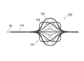
図1は、第1実施形態に係る異物除去用カテーテル50を説明するために示す図である。
図2は、異物除去用カテーテル50の内部構造を模式的に示す図である。図2(a)はリトリバー120を拡張させたときの異物除去用カテーテル50の内部構造を示しており、図2(b)はリトリバー120を収縮させたときの異物除去用カテーテル50の内部構造を示している。なお、図2(a)及び図2(b)において、発明の理解を容易にするため、異物除去用カテーテル50を構成する各部材の長さや肉厚等を誇張して図示している。FIG. 1 is a view for explaining a foreign
FIG. 2 is a diagram schematically showing the internal structure of the foreign
第1実施形態に係る異物除去用カテーテル50は、図1並びに図2(a)及び図2(b)に示すように、カテーテル本体60と、カテーテル本体60の遠位部に配置された異物除去デバイス100と、カテーテル本体60の近位部に配置された操作部70とを備える。異物除去用カテーテル50は、例えば、血管内に発生した血栓又は塞栓などの異物を除去するための血栓除去用カテーテルである。
As shown in FIGS. 1 and 2(a) and 2(b), the foreign
なお、この明細書において「遠位部」とは、異物除去用カテーテル50の使用者からみて遠いほうの端部側の領域を指し、「近位部」とは、異物除去用カテーテル50の使用者からみて近いほうの端部側(手元側)の領域を指す。
In this specification, the term “distal portion” refers to a region on the far side of the foreign
カテーテル本体60は、図2(a)及び図2(b)に示すように、カテーテル本体60の遠位部から近位部まで伸びる第1チューブ62と、異物除去デバイス100と操作部70とを接続する第2チューブ64とを有する。第1チューブ62には、ガイドワイヤを挿通させるためのガイドワイヤ用ルーメンが設けられている。図2(a)及び図2(b)に示すように、異物除去デバイス100の遠位部側の端部は、第1チューブ62の遠位部の外周面に接続されており、異物除去デバイス100の近位部側の端部は、第2チューブ64の遠位部の内周面に接続されている。第2チューブ64の内径は、第1チューブ62の外径よりも大きく設定されており、第1チューブ62と第2チューブ64との間に、所定寸法の隙間が設けられている。
As shown in FIGS. 2(a) and 2(b), the
第1チューブ62及び第2チューブ64は、ともに可撓性を有する材料で形成されている。可撓性材料としては、例えば、合成樹脂(エラストマー)、合成樹脂に他の材料が混合された樹脂コンパウンド、合成樹脂が多層で構成された多層構造体、または合成樹脂と金属線との複合体などを好ましく用いることができる。
Both the
操作部70は、例えばスティック状(棒状)の操作部本体72と、操作部本体72の側面に設置されたスライダー76と、操作部本体72の側面に設けられた液体充填ポート78とを有する。
The operating
操作部本体72の側面には、長手方向(管軸方向)に沿って伸びる長孔74が設けられている。スライダー76は、長孔74を介して第1チューブ62に接続されており、長手方向(管軸方向)に沿って平行移動可能に構成されている。
A
液体充填ポート78は、第2チューブ64の内部ルーメン(第1チューブ62と第2チューブ64の隙間)に連通しており、液体充填ポート78を介してカテーテル本体60内に例えば生理食塩水等の液体を充填可能に構成されている。なお、図示による説明は省略するが、液体充填ポート78の開口端部は、キャップ等の封止部材又はシリコンゴム等からなる弁体によって液密に閉鎖されている。
The
ここで、スライダー76を移動させたときの異物除去デバイス100の動きについて、図2(a)及び図2(b)を用いて説明する。
まず、図2(a)に示す状態において、スライダー76を矢印X1方向に移動させると、スライダー76に接続された第1チューブ62もX1方向に移動する。このとき、第1チューブ62と異物除去デバイス100との接続位置はX1方向に移動するが、異物除去デバイス100と第2チューブ64との接続位置は変化しない。つまり、第2チューブ64に対して第1チューブ62がX1方向に相対的に移動する結果、リトリバー120が収縮することとなる(図2(b)参照。)。
一方、図2(b)に示す状態において、スライダー76を矢印X2方向に移動させると、スライダー76に接続された第1チューブ62もX2方向に移動する。このとき、第1チューブ62と異物除去デバイス100との接続位置はX2方向に移動するが、異物除去デバイス100と第2チューブ64との接続位置は変化しない。つまり、第2チューブ64に対して第1チューブ62がX2方向に相対的に移動する結果、リトリバー120が拡張することとなる(図2(a)参照。)。
すなわち、スライダー76を長手方向(管軸方向)に沿って平行移動させることにより、後述するリトリバー120の拡張及び収縮を操作することができる。Here, movement of the foreign
First, when the
On the other hand, when the
That is, by moving the
次に、第1実施形態に係る異物除去デバイス100の構成について、図3~図6を用いて説明する。
Next, the configuration of the foreign
図3は、第1実施形態に係る異物除去デバイス100の拡大斜視図である。
図4は、リトリバー120を説明するために示す図である。図4(a)はリトリバー120の拡大正面図であり、図4(b)は補助線材124の配置パターンを説明するために示す図である。図4(b)をさらに説明すると、図4(a)に示すリトリバー120から、隣り合う2本の主線材122とその間に配置された補助線材124及び規制部126を抜き出し、各部材を平面的に図示している。
図5は、リトリバー120の拡大左側面図である。
図6は、リトリバー120の拡張及び収縮する様子を説明するために示す図である。図6(a)はリトリバー120が最も拡張した状態を示しており、図6(d)はリトリバー120が最も収縮した状態を示しており、図6(b)及び図6(c)は拡張状態から収縮状態へと移行する間の状態を示している。FIG. 3 is an enlarged perspective view of the foreign
FIG. 4 is a diagram shown for explaining the
FIG. 5 is an enlarged left side view of the
FIG. 6 is a diagram for explaining how the
異物除去デバイス100は、図1及び図3に示すように、管状部材110と、管状部材110の遠位部に配置されたリトリバー120とを備える。
The foreign
管状部材110は、例えば、断面円形状のパイプ状部材である。管状部材110を構成する材料としては、例えば、ステンレス鋼、チタン合金、Ni-Ti合金、Ni―Ti―Co合金、Ni―Ti―Cu合金、Au―Cd合金、Cu―Al-Ni合金などに代表される公知の金属又は金属合金を好ましく用いることができる。また、材料としてX線造影性を有する合金を用いることにより、X線不透過マーカーとしてもよい。この場合、管状部材及びリトリバーの位置を体外から確認することができる。
The
管状部材110の外面には、管軸に直交する方向に伸びる切れ込み(スリット)が無数に形成されている。これにより、管状部材110の柔軟性を向上させることができる。管状部材110の外面に切れ込みを形成する方法としては、例えば、レーザー加工を好ましく用いることができる。
The outer surface of the
リトリバー120は、図4(a)及び図4(b)並びに図5に示すように、管状部材110の管軸を中心として配置された主線材122と、隣り合う主線材122同士をそれぞれ繋ぐ補助線材124と、補助線材124の屈曲部位124Fに接続された規制部126とを有する。
As shown in FIGS. 4(a), 4(b) and 5, the
リトリバー120は、図6(a)~図6(d)に示すように、拡張及び収縮可能に構成されており、例えば拡張状態の形状が記憶されている。拡張時のリトリバー120の形状は、例えば略球状である。
The
リトリバー120を構成する主線材122の数は、図5から明らかなように、例えば8本であり、管状部材110の管軸を中心として互いに等間隔となるように(管軸中心に45度の配置間隔で)配置されている。
As is clear from FIG. 5, the number of
各主線材122は、リトリバー120を拡張させたときに8本の主線材122によって所定広さの空間S(図6(a)参照。)が設けられるよう、湾曲可能に構成されている。
Each
複数の補助線材124のそれぞれは、図4(a)及び図4(b)に示すように、屈曲部位124Fから隣り合う主線材122に向けて広がるように延びる一対の腕状部位124Gが互いに近付くように(換言すると、略V字状に)屈曲可能に構成されており、かつ、リトリバー120の中間部からリトリバー120の端部に向けて凸となるように配置されている。
As shown in FIGS. 4(a) and 4(b), each of the
図4(b)を参照し、リトリバー120の中間部からリトリバー120の左端部(遠位部側の端部)までを「第1領域A1」とし、リトリバー120の中間部からリトリバーの右端部(近位部側の端部)までを「第2領域A2」としたとき、第1領域A1に配置される補助線材124は、リトリバー120の左端部に向けて凸となるように配置されている。一方、第2領域A2に配置される補助線材124は、リトリバー120の右端部に向けて凸となるように配置されている。また、第1領域A1に配置される補助線材124と第2領域A2に配置される補助線材124とは、リトリバー120の中間部を境として対称形である。
With reference to FIG. 4(b), the middle portion of the
なお、この明細書において「リトリバー120の中間部」とは、リトリバー120の端部(左端部及び右端部)を除く領域を意味する。
In this specification, the term “intermediate portion of the
規制部126は、補助線材124の屈曲部位124Fとリトリバー120の端部(左端部又は右端部)とをそれぞれ連結している。補助線材124と規制部126とを結んだときの平面形状は、図4(b)に示すように、略Y字状である。
The
主線材122、補助線材124及び規制部126を構成する材料としては、例えば、ステンレス鋼、Ni-Ti合金、チタン合金などに代表される公知の金属又は金属合金を好ましく用いることができる。また、主線材122、補助線材124及び規制部126は、ともに超弾性(変形しても力を取り除くとすぐに元の形に戻る性質)を有する材料から構成されている。超弾性を有する材料として、例えばNi-Ti合金を好適に用いることができる。
As materials for forming the
また、図示による説明は省略するが、管状部材110とリトリバー120は、1本の金属パイプ(例えばNi-Ti合金からなるパイプ)をレーザー加工することによって形成することができる。この場合、管状部材110とリトリバー120とを一体形成することができ、リトリバー120を構成する主線材122、補助線材124及び規制部126も、一体形成することができる。
Also, although not illustrated, the
図示による説明は省略するが、主線材122、補助線材124及び規制部126の断面形状は、例えば略矩形状である。また、主線材122のほうが補助線材124よりも断面積が大きく(線材が太く)なるように設定されており、主線材122のほうが補助線材124よりも剛性が高い。
Although not illustrated, the
ここで、補助線材の屈曲部位の位置について、図7及び図8を用いて詳細に説明する。
図7は、比較例に係るリトリバー820を説明するために示す図である。図7(a)は比較例に係るリトリバー820の拡大正面図であり、図7(b)は比較例に係るリトリバー820における補助線材824の配置パターンを説明するために示す図である。
図8は、比較例及び第1実施形態に係るリトリバー820,120を説明するために示す図である。図8(a)は、図7(a)のB-B線端面図であって、比較例に係るリトリバー820について、補助線材824の屈曲部位824Fの位置を説明するために示す図である。図8(b)は、図4(a)のA-A線端面図であって、第1実施形態に係るリトリバー120について、補助線材124の屈曲部位124Fの位置を説明するために示す図である。Here, the position of the bent portion of the auxiliary wire will be described in detail with reference to FIGS. 7 and 8. FIG.
FIG. 7 is a diagram for explaining a
FIG. 8 is a diagram shown for explaining
比較例に係るリトリバー820は、基本的には第1実施形態に係るリトリバー120と同様の構成を有するが、図7(a)及び図7(b)に示すように、規制部を備えていない点で、第1実施形態に係るリトリバー120とは異なる。また、リトリバー820を拡張させたときの補助線材824の屈曲部位824Fは、主線材822よりも外側に飛び出しており、8本の主線材822によって形成される空間内には位置していない。比較例に係るリトリバー820においては、図8(a)から明らかなように、補助線材824の屈曲部位824Fは、主線材822よりも外側に位置している。
The
これに対し、第1実施形態に係るリトリバー120においては、図4(a)及び図4(b)に示すように、規制部126を備えている。また、リトリバーを拡張させたときの補助線材124の屈曲部位124Fは、補助線材124が主線材122よりも外側に出っ張らないよう、8本の主線材122によって形成される空間S(図6(a)参照。)内に位置している。また、図8(b)から明らかなように、補助線材124の屈曲部位124Fは、主線材122よりも内側に位置している。
On the other hand, in the
次に、異物除去用カテーテル50の使用方法の一例を、図9を用いて説明する。
Next, an example of how to use the foreign
図9(a)~図9(f)は、異物除去用カテーテル50を用いて血管内の異物を除去する流れを説明するために示す図である。なお、図9(a)~図9(f)において、発明の理解を容易にするため、異物除去用カテーテル50を構成する各部材の形状等を模式的に図示している。
FIGS. 9(a) to 9(f) are diagrams for explaining the flow of removing a foreign substance in a blood vessel using the foreign
まず、図9(a)に示すように、血管内にガイドワイヤWを通した状態で、ガイドワイヤWに沿わせてガイディングカテーテルGCを血管内に挿入し、標的部位(異物CLが存在する部位)の手前まで異物除去用カテーテル50を送達する。
First, as shown in FIG. 9A, a guiding catheter GC is inserted into the blood vessel along the guide wire W in a state where the guide wire W is passed through the blood vessel. The foreign
次に、図9(b)に示すように、ガイディングカテーテルGCから異物除去用カテーテル50を送り出し、リトリバー120を収縮させた状態で異物CLを貫通させて、リトリバー120を標的部位よりも遠位に配置する。
Next, as shown in FIG. 9(b), the foreign
次に、図9(c)に示すように、リトリバー120を拡張させた状態で、異物除去用カテーテル50を手元側に引き寄せ、リトリバー120で異物CLを絡め取る(図9(d)参照。)。リトリバー120に異物CLを絡め取るために、例えば、標的部位においてリトリバー120を管軸中心に回転させてもよいし、標的部位においてリトリバー120を前進及び後退させてもよいし、標的部位においてリトリバー120を拡張及び収縮してもよい。
Next, as shown in FIG. 9(c), with the
そして、図9(e)に示すように、異物CLを絡めたままリトリバー120を収縮させて、リトリバー120(異物除去用カテーテル50)をガイディングカテーテルGC内に引き込む(図9(f)参照。)。その後、ガイディングカテーテルGCの内部から異物除去用カテーテル50を抜き取る作業を行うことにより、経皮的に異物CLを体外に取り出すことができる。
Then, as shown in FIG. 9(e), the
以上のように構成された第1実施形態に係る異物除去デバイス100によれば、8本の主線材122が、リトリバー120を拡張させたときに所定広さの空間Sを設けるように構成されているとともに、リトリバー120を拡張させたときに補助線材124が主線材122よりも外側に出っ張らないよう、補助線材124の屈曲部位124Fが空間S内に位置するように構成されている。このため、リトリバー120を拡張させた状態でリトリバー120を回転させたり、血管内でリトリバー120を前進又は後退させたりしたとしても、補助線材124の屈曲部位124Fが血管に引っ掛かりにくくなる。その結果、血管を損傷するリスクを低減しつつ、血管の内部に発生した異物を除去又は回収することが可能となる。
According to the foreign
第1実施形態に係る異物除去デバイス100によれば、複数の規制部126を備えているため、リトリバー120を拡張させたときに補助線材124が主線材122よりも外側に出っ張らないよう、補助線材124の屈曲部位124Fの位置を上記空間S内に維持し続けることができる。その結果、血管の損傷リスクをさらに低減することが可能となる。
According to the foreign
第1実施形態に係る異物除去デバイス100によれば、複数の補助線材として、屈曲部位124Fから隣り合う主線材122に向けて広がるように延びる一対の腕状部位124Gが互いに近付くように(換言すると、略V字状に)屈曲可能に構成された補助線材124を用いるとともに、補助線材124の屈曲部位124Fとリトリバー120の端部とを規制部126で連結するように構成されているため、血管の損傷リスクの低減を図ることが可能な異物除去デバイスを、比較的簡単な構成でもって実現することが可能となる。
According to the foreign
第1実施形態に係る異物除去デバイス100によれば、上記第1領域A1及び第2領域A2(図4(b)参照。)に配置される複数の補助線材124が、リトリバー120の中間部を境として対称形である。このため、リトリバー120を比較的均一に拡張させることができ、血管内の異物を効果的に除去又は回収することが可能となる。
According to the foreign
ところで、主線材の剛性が補助線材の剛性よりも極端に低くなると、リトリバーを拡張させたときに主線材が思いどおりに拡張しなかったり、隣り合う主線材同士の間隔が均一とならずに偏ってしまったりするなどの不具合が発生することが考えられる。
これに対し、第1実施形態に係る異物除去デバイス100によれば、主線材122の剛性が補助線材124の剛性よりも高いことから、主線材122を思い通りに拡張させやすく、かつ、隣り合う主線材122同士の間隔を比較的均一に保つことが可能な、優れた血栓除去デバイスとなる。By the way, if the rigidity of the main wire is extremely lower than the rigidity of the auxiliary wire, the main wire may not expand as expected when the retriever is expanded, or the intervals between adjacent main wires may be uneven and uneven. It is conceivable that troubles such as being stuck or getting stuck may occur.
In contrast, according to the foreign
第1実施形態に係る異物除去デバイス100によれば、拡張時におけるリトリバー120の形状が略球状であるため、断面円形の血管に対して、拡張させたリトリバー120がよりフィットするようになる。その結果、血管の内壁にこびり付いた異物をも効果的に除去することが可能となる。
According to the foreign
第1実施形態に係る異物除去デバイス100によれば、主線材122、補助線材124及び規制部126は、ともに超弾性を有する材料からなり、拡張状態の形状が記憶されていることから、リトリバー120を拡張させた際の形状を安定化することができる。
According to the foreign
第1実施形態に係る異物除去用カテーテル50は、上述した異物除去デバイス100を備えているため、血管を損傷するリスクを低減しつつ、血管の内部に発生した異物を除去又は回収することが可能な異物除去用カテーテルとなる。
Since the foreign
[第2実施形態]
図10は、第2実施形態に係るリトリバー220を説明するために示す図である。図10(a)はリトリバー220の拡大正面図であり、図10(b)はリトリバー220における補助線材224の配置パターンを説明するために示す図である。図10(b)をさらに説明すると、図10(a)に示すリトリバー220から、隣り合う2本の主線材222とその間に配置された補助線材224及び規制部226を抜き出し、各部材を平面的に図示している。[Second embodiment]
FIG. 10 is a diagram shown for explaining the
第2実施形態に係る異物除去デバイスは、基本的には第1実施形態に係る異物除去デバイス100と同様の構成を有するが、リトリバーの構成が、第1実施形態に係る異物除去デバイス100とは異なる。
The foreign matter removing device according to the second embodiment basically has the same configuration as the foreign
第2実施形態に係るリトリバー220は、図10(a)及び図10(b)に示すように、8本の主線材222と、隣り合う主線材222同士をそれぞれ繋ぐ補助線材224と、補助線材224の屈曲部位224Fに接続された規制部226とを有する。屈曲部位224Fから隣り合う主線材222に向けて広がるように、一対の腕状部位224Gが延びている。
As shown in FIGS. 10A and 10B, the
主線材222及び補助線材224の構成については、第1実施形態で説明した主線材122及び補助線材124と同様であるため、詳細な説明を省略する。
Since the configurations of the
規制部226は、補助線材224の屈曲部位224Fとリトリバー220の端部(左端部又は右端部)とをそれぞれ連結している。第1実施形態で説明した規制部126と比較すると、第1実施形態の規制部126は、図4(b)に示すように、第1領域A1及び第2領域A2にそれぞれ1本ずつ配置されているのに対し、第2実施形態の規制部226は、図10(b)に示すように、第1領域A1及び第2領域A2にそれぞれ3本ずつ配置されている。
The restricting
主線材222、補助線材224及び規制部226を構成する材料については、第1実施形態で説明した主線材122、補助線材124及び規制部126と同一であるため、詳細な説明を省略する。
Materials forming the
第2実施形態に係る異物除去デバイスの構成部品のうちリトリバー220以外(例えば管状部材等)の構成については、第1実施形態で説明したものと同様であるため、詳細な説明を省略する。 Of the constituent parts of the foreign matter removing device according to the second embodiment, the configurations other than the retriever 220 (for example, the tubular member, etc.) are the same as those explained in the first embodiment, so detailed explanations thereof will be omitted.
このように、第2実施形態に係る異物除去デバイスは、リトリバーの構成(規制部の本数)が異なる点で、第1実施形態に係る異物除去デバイス100とは異なっているが、第1実施形態に係る異物除去デバイス100の場合と同様に、8本の主線材222が、リトリバー220を拡張させたときに所定広さの空間を設けるように構成されているとともに、リトリバー220を拡張させたときに補助線材224が主線材222よりも外側に出っ張らないよう、補助線材224の屈曲部位224Fが当該空間内に位置するように構成されている。このため、リトリバー220を拡張させた状態でリトリバー220を回転させたり、血管内でリトリバー220を前進又は後退させたりしたとしても、補助線材224の屈曲部位224Fが血管に引っ掛かりにくくなる。その結果、血管を損傷するリスクを低減しつつ、血管の内部に発生した異物を除去又は回収することが可能となる。
As described above, the foreign matter removing device according to the second embodiment differs from the foreign
第2実施形態に係る異物除去デバイスにおいては、図10(b)に示すように、規制部226が第1領域A1及び第2領域A2にそれぞれ3本ずつ配置されているため、補助線材224の屈曲部位224Fの位置を上記空間内に維持し続ける力を、より高めることができる。その結果、管状組織の損傷リスクをより一層低減することが可能となる。
In the foreign matter removing device according to the second embodiment, as shown in FIG. It is possible to further increase the force that keeps the position of the
第2実施形態に係る異物除去デバイスは、リトリバーの構成(規制部の本数)が異なる点以外の点では、第1実施形態に係る異物除去デバイス100の場合と同様の構成を有しているため、第1実施形態に係る異物除去デバイス100が有する効果のうち該当する効果をそのまま有する。
The foreign matter removing device according to the second embodiment has the same configuration as the foreign
[第3実施形態]
図11は、第3実施形態に係るリトリバー320における補助線材324の配置パターンを説明するために示す図である。
なお、図11においては、リトリバー320全体のうち、隣り合う2本の主線材322とその間に配置された補助線材324及び規制部326を抜き出し、各部材を平面的に図示している。[Third embodiment]
FIG. 11 is a diagram for explaining the arrangement pattern of the
In addition, in FIG. 11, two adjacent
第3実施形態に係る異物除去デバイスは、基本的には第1実施形態に係る異物除去デバイス100と同様の構成を有するが、リトリバーの構成が、第1実施形態に係る異物除去デバイス100とは異なる。
The foreign matter removing device according to the third embodiment basically has the same configuration as the foreign
第3実施形態に係るリトリバー320は、図11に示すように、主線材322と、隣り合う主線材322同士をそれぞれ繋ぐ補助線材324と、補助線材324の屈曲部位324Fに接続された規制部326とを有する。
A
主線材322の構成については、第1実施形態で説明した主線材122と同様であるため、詳細な説明を省略する。
また、リトリバー320を構成する主線材322の数について、図示による説明は省略するが、第1実施形態で説明したリトリバー120と同様に8本であり、管状部材の管軸を中心として互いに等間隔となるように(管軸中心に45度の配置間隔で)配置されている。Since the configuration of the
In addition, the number of the
複数の補助線材324のそれぞれは、図11に示すように、隣り合う主線材322の間において2箇所で屈曲可能(略W字状に屈曲可能)に構成されており、かつ、リトリバー320の中間部からリトリバー320の端部に向けて凸となるように配置されている。また、第1領域A1に配置される補助線材324と第2領域A2に配置される補助線材324とは、リトリバー320の中間部を境として対称形である。2箇所の屈曲部位324Fのそれぞれから隣り合う主線材322に向けて広がるように、一対の腕状部位324Gが延びている。より具体的には、一方の(図中上側の)屈曲部位324Fから延びる腕状部位324Gの一方は、図中上側の主線材322に繋がっており、他方の(図中下側の)屈曲部位324Fから延びる腕状部位324Gの一方は、図中下側の主線材322に繋がっている。更に、一方の(図中上側の)屈曲部位324Fから延びる腕状部位324Gの他方と、他方の(図中下側の)屈曲部位324Fから延びる腕状部位324Gの他方とは、互いに繋がっている。
As shown in FIG. 11, each of the plurality of
規制部326は、補助線材324の屈曲部位324Fとリトリバー320の端部(左端部又は右端部)とをそれぞれ連結している。第1実施形態で説明した規制部126と比較すると、第1実施形態の規制部126は、図4(b)に示すように、第1領域A1及び第2領域A2にそれぞれ1本ずつ配置されているのに対し、第3実施形態の規制部326は、図11に示すように、第1領域A1及び第2領域A2にそれぞれ2本ずつ配置されている。
The restricting
主線材322、補助線材324及び規制部326を構成する材料については、第1実施形態で説明した主線材122、補助線材124及び規制部126と同一であるため、詳細な説明を省略する。
Materials forming the
第3実施形態に係る異物除去デバイスの構成部品のうちリトリバー320以外(例えば管状部材等)の構成については、第1実施形態で説明したものと同様であるため、詳細な説明を省略する。 Of the constituent parts of the foreign matter removing device according to the third embodiment, the configurations other than the retriever 320 (for example, the tubular member, etc.) are the same as those explained in the first embodiment, so detailed explanations are omitted.
このように、第3実施形態に係る異物除去デバイスは、リトリバーの構成(補助線材及び規制部の構成)が異なる点で、第1実施形態に係る異物除去デバイス100とは異なっているが、第1実施形態に係る異物除去デバイス100の場合と同様に、8本の主線材322が、リトリバー320を拡張させたときに所定広さの空間を設けるように構成されているとともに、リトリバー320を拡張させたときに補助線材324が主線材322よりも外側に出っ張らないよう、補助線材324の屈曲部位324Fが当該空間内に位置するように構成されている。このため、リトリバー320を拡張させた状態でリトリバー320を回転させたり、血管内でリトリバー320を前進又は後退させたりしたとしても、補助線材324の屈曲部位324Fが血管に引っ掛かりにくくなる。その結果、血管を損傷するリスクを低減しつつ、血管の内部に発生した異物を除去又は回収することが可能となる。
As described above, the foreign matter removing device according to the third embodiment differs from the foreign
第3実施形態に係る異物除去デバイスは、リトリバーの構成(補助線材及び規制部の構成)が異なる点以外の点では、第1実施形態に係る異物除去デバイス100の場合と同様の構成を有しているため、第1実施形態に係る異物除去デバイス100が有する効果のうち該当する効果をそのまま有する。
The foreign matter removing device according to the third embodiment has the same configuration as the foreign
[第4実施形態]
図12は、第4実施形態に係るリトリバー420における補助線材424の配置パターンを説明するために示す図である。
なお、図12においては、リトリバー420全体のうち、隣り合う2本の主線材422とその間に配置された補助線材424及び規制部426を抜き出し、各部材を平面的に図示している。[Fourth embodiment]
FIG. 12 is a diagram for explaining the arrangement pattern of the
In addition, in FIG. 12, two adjacent
第4実施形態に係る異物除去デバイスは、基本的には第1実施形態に係る異物除去デバイス100と同様の構成を有するが、リトリバーの構成が、第1実施形態に係る異物除去デバイス100とは異なる。
The foreign matter removing device according to the fourth embodiment basically has the same configuration as the foreign
第4実施形態に係るリトリバー420は、図12に示すように、主線材422と、隣り合う主線材422同士をそれぞれ繋ぐ補助線材424と、補助線材424の屈曲部位424Fに接続された規制部426とを有する。屈曲部位424Fから隣り合う主線材422に向けて広がるように、一対の腕状部位424Gが延びている。
A
主線材422の構成については、第1実施形態で説明した主線材122と同様であるため、詳細な説明を省略する。
また、リトリバー420を構成する主線材422の数について、図示による説明は省略するが、第1実施形態で説明したリトリバー120と同様に8本であり、管状部材の管軸を中心として互いに等間隔となるように(管軸中心に45度の配置間隔で)配置されている。Since the configuration of the
In addition, the number of the
複数の補助線材424のそれぞれは、図12に示すように、一対の腕状部位424Gが互いに近付くように(換言すると、略V字状に)屈曲可能に構成されており、かつ、リトリバー420の各端部からリトリバー420の中間部に向けて凸となるように配置されている。また、第1領域A1に配置される補助線材424と第2領域A2に配置される補助線材424とは、リトリバー420の中間部を境として対称形である。第1実施形態で説明した補助線材124と第4実施形態の補助線材424とを比較すると、第4実施形態の補助線材424は、配置されている向きが逆である。
As shown in FIG. 12, each of the plurality of
規制部426は、補助線材424の屈曲部位424F同士を連結している。第1実施形態で説明した規制部126と比較すると、第1実施形態の規制部126は、図4(b)に示すように、第1領域A1及び第2領域A2にそれぞれ1本ずつ配置されているのに対し、第4実施形態の規制部426は、図12に示すように、第1領域A1から第2領域A2に渡って1本配置されている。
The restricting
主線材422、補助線材424及び規制部426を構成する材料については、第1実施形態で説明した主線材122、補助線材124及び規制部126と同一であるため、詳細な説明を省略する。
Materials forming the
第4実施形態に係る異物除去デバイスの構成部品のうちリトリバー420以外(例えば管状部材等)の構成については、第1実施形態で説明したものと同様であるため、詳細な説明を省略する。 Of the constituent parts of the foreign matter removing device according to the fourth embodiment, the configurations other than the retriever 420 (for example, the tubular member, etc.) are the same as those explained in the first embodiment, so detailed explanations thereof will be omitted.
このように、第4実施形態に係る異物除去デバイスは、リトリバーの構成(補助線材及び規制部の構成)が異なる点で、第1実施形態に係る異物除去デバイス100とは異なっているが、第1実施形態に係る異物除去デバイス100の場合と同様に、8本の主線材422が、リトリバー420を拡張させたときに所定広さの空間を設けるように構成されているとともに、リトリバー420を拡張させたときに補助線材424が主線材422よりも外側に出っ張らないよう、補助線材424の屈曲部位424Fが当該空間内に位置するように構成されている。このため、リトリバー420を拡張させた状態でリトリバー420を回転させたり、血管内でリトリバー420を前進又は後退させたりしたとしても、補助線材424の屈曲部位424Fが血管に引っ掛かりにくくなる。その結果、血管を損傷するリスクを低減しつつ、血管の内部に発生した異物を除去又は回収することが可能となる。
As described above, the foreign matter removing device according to the fourth embodiment differs from the foreign
第4実施形態に係る異物除去デバイスは、リトリバーの構成(補助線材及び規制部の構成)が異なる点以外の点では、第1実施形態に係る異物除去デバイス100の場合と同様の構成を有しているため、第1実施形態に係る異物除去デバイス100が有する効果のうち該当する効果をそのまま有する。
The foreign matter removing device according to the fourth embodiment has the same configuration as the foreign
[第5実施形態]
第5実施形態では、本発明の異物回収システムの一例として、血管内に発生した血栓又は塞栓などの異物を除去するための血栓回収システムを例示して説明する。[Fifth embodiment]
In the fifth embodiment, as an example of the foreign body recovery system of the present invention, a thrombus recovery system for removing a foreign body such as a thrombus or an embolism generated in a blood vessel will be described.
図13は、第5実施形態に係る異物回収システム1を説明するために示す図である。
図14(a)~図14(f)は、異物回収システム1の使用方法を説明するために示す図である。FIG. 13 is a diagram for explaining the foreign
FIGS. 14(a) to 14(f) are diagrams for explaining how to use the foreign
第5実施形態に係る異物回収システム1は、図13に示すように、血管内の異物を除去するための異物除去用カテーテル50と、血管内の異物を捕捉するための異物捕捉用カテーテル10とを備える。
As shown in FIG. 13, the foreign
図13に示す異物除去用カテーテル50は、第1実施形態で説明した異物除去用カテーテル50と同一であるため、詳細な説明は省略する。
Since the foreign
異物捕捉用カテーテル10は、カテーテルチューブ20と、カテーテルチューブ20の遠位部に配置されたキャプチャー30と、カテーテルチューブ20の近位部に配置された基部40とを備える。異物捕捉用カテーテル10は、例えば、血管内に発生した血栓又は塞栓などの異物を捕捉するための血栓捕捉用カテーテルである。
The foreign
図示による説明は省略するが、カテーテルチューブ20及び基部40の内部にはルーメンが設けられており、異物除去用カテーテル50を通すことができるように構成されている。
Although not illustrated, a lumen is provided inside the
カテーテルチューブ20を構成する材料については、異物除去用カテーテル50における第1チューブ62及び第2チューブ64と同様であるため、詳細な説明は省略する。
Since the materials constituting the
キャプチャー30は、略円筒形状の網部32と、網部32全体を覆うように形成された膜部34とを有する。
The
網部32の近位部は、近位部側(手元側)から遠位部側(先端側)に向かうにしたがって徐々に拡径するテーパー形状である。網部32の先端部分は、キャプチャー30を拡張させたときに開口するように構成されている。
The proximal portion of the
網部32は、例えば金属細線を格子状に編み込んだ構造からなる。網部32に用いる金属細線の材料としては、例えば、ステンレス鋼、Ni-Ti合金、チタン合金などに代表される公知の金属又は金属合金を好ましく用いることができる。また、網部32は、超弾性を有する材料から構成されている。超弾性を有する材料として、例えばNi-Ti合金を好適に用いることができる。また、詳細については後述するが、網部32は、半径方向(管軸に直交する方向)に拡張及び収縮可能に構成されており、例えば拡張状態の形状が記憶されている。
The
膜部34を構成する材料としては、例えば、PTFE(ポリテトラフルオロエチレン)等のフッ素樹脂や、ポリウレタン樹脂などを好ましく用いることができる。これらの樹脂材料によって作成された膜状部材は、生体適合性及び耐久性が比較的高く、かつ、化学的にも安定している。
As a material for forming the
基部40の側面には、内部ルーメンに連通するポート42が設けられており、ポート42を介してカテーテルチューブ20内に例えば生理食塩水等の液体を充填可能に構成されている。なお、図示による説明は省略するが、ポート42の開口端部は、キャップ等の封止部材又はシリコンゴム等からなる弁体によって液密に閉鎖されている。
A
次に、異物回収システム1の使用方法の一例を、図14を用いて説明する。
Next, an example of how to use the foreign
図14(a)~図14(f)は、異物回収システム1を用いて血管内の異物を除去する流れを説明するために示す図である。なお、図14(a)~図14(f)において、発明の理解を容易にするため、異物回収システム1を構成する各部材の形状等を模式的に図示している。
FIGS. 14(a) to 14(f) are diagrams for explaining the flow of removing a foreign substance in a blood vessel using the foreign
まず、図14(a)に示すように、血管内にガイドワイヤWを通した状態で、ガイドワイヤWに沿わせてガイディングカテーテルGCを血管内に挿入し、標的部位(異物CLが存在する部位)の手前まで異物捕捉用カテーテル10を送達する。
First, as shown in FIG. 14(a), the guiding catheter GC is inserted into the blood vessel along the guide wire W in a state where the guide wire W is passed through the blood vessel, and the target site (the foreign body CL is present). The foreign
次に、図14(b)に示すように、異物捕捉用カテーテル10の位置を固定した状態でガイディングカテーテルGCを手元側に引き寄せ、ガイディングカテーテルGCからキャプチャー30を露出させる。これにより、血管壁と密着するようにキャプチャー30が拡張する。
Next, as shown in FIG. 14(b), the guiding catheter GC is pulled toward the proximal side while the position of the foreign
次に、図14(c)に示すように、異物捕捉用カテーテル10の内部ルーメンを介して異物除去用カテーテル50を送り出し、リトリバー120を収縮させた状態で異物CLを貫通させて、リトリバー120を標的部位よりも遠位に配置する。
Next, as shown in FIG. 14(c), the foreign
次に、リトリバー120を拡張させた状態(図14(d)参照。)で、異物除去用カテーテル50を手元側に引き寄せ、異物CLをキャプチャー30内に取り込む(図14(e)参照。)。
Next, with the
そして、異物CLをキャプチャー30内に取り込んだ状態で、キャプチャー30をガイディングカテーテルGC内に引き込む(図14(f)参照。)。その後、ガイディングカテーテルGCの内部から異物捕捉用カテーテル10を抜き取る作業を行うことにより、経皮的に異物CLを体外に取り出すことができる。
Then, the
第5実施形態に係る異物回収システム1は、上述した異物除去用カテーテル50を備えているため、血管を損傷するリスクを低減しつつ、血管の内部に発生した異物を除去又は回収することが可能な異物回収システムとなる。
Since the foreign
なお、本発明は上記実施形態に例示したものに限定されるものではなく、本発明の要旨を逸脱しない範囲において種々の態様において実施することが可能であり、例えば次のような変形も可能である。 The present invention is not limited to the above-described embodiments, and can be implemented in various aspects without departing from the scope of the present invention. For example, the following modifications are possible. be.
(1)上記実施形態においては、複数の補助線材のそれぞれが、隣り合う主線材の間において1箇所又は2箇所で屈曲可能に構成されている場合を例示して説明したが、本発明はこれに限定されるものではない。複数の補助線材のそれぞれは、隣り合う主線材の間において3箇所以上で屈曲可能に構成されていてもよい。隣り合う主線材の間において複数の補助線材のそれぞれが3箇所以上で屈曲可能に構成されている場合、補助線材の屈曲数に合わせて、規制部の数を変更してもよい。また、上記実施形態においては、規制部を備えることによって補助線材における屈曲部位の位置が規制されている場合を例示して説明したが、本発明はこれに限定されるものではない。規制部を設けずに、例えば補助線材を予めクセ付けする等の加工を施しておくことにより、補助線材の屈曲部位が、リトリバーを拡張させたときに補助線材が複数の主線材よりも外側に出っ張らないように構成されていてもよい。 (1) In the above embodiment, each of the plurality of auxiliary wires is configured to be bendable at one or two locations between adjacent main wires. is not limited to Each of the plurality of auxiliary wires may be configured to be bendable at three or more points between adjacent main wires. When each of a plurality of auxiliary wires is configured to be bendable at three or more points between adjacent main wires, the number of restricting portions may be changed according to the number of bends of the auxiliary wire. Further, in the above embodiment, the case where the position of the bent portion of the auxiliary wire is regulated by providing the regulating portion has been exemplified and explained, but the present invention is not limited to this. For example, by processing the auxiliary wire rod in advance without providing a restricting part, the bent portion of the auxiliary wire rod will be outside the plurality of main wires when the retriever is expanded. It may be configured so as not to protrude.
(2)上記実施形態においては、第1領域に配置される補助線材と第2領域に配置される補助線材とが、リトリバーの中間部を境として対称形である場合を例示して説明したが、本発明はこれに限定されるものではない。第1領域に配置される補助線材と第2領域に配置される補助線材とが、リトリバーの中間部を境として非対称形であってもよい。 (2) In the above embodiment, the auxiliary wire arranged in the first region and the auxiliary wire arranged in the second region are symmetrical with respect to the intermediate portion of the retriever. , the invention is not limited thereto. The auxiliary wire arranged in the first region and the auxiliary wire arranged in the second region may be asymmetric with respect to the intermediate portion of the retriever.
(3)上記実施形態においては、拡張時におけるリトリバーの形状が、略球状である場合を例示して説明したが、本発明はこれに限定されるものではない。例えば、球状、長球状、扁球状又は鶏卵状であってもよいし、リトリバーの各端部が長球状であって、リトリバーの中間部が円筒状からなる形状であってもよい。 (3) In the above embodiment, the shape of the retriever at the time of expansion has been described as being approximately spherical, but the present invention is not limited to this. For example, it may be spherical, spheroidal, oblate, or egg-shaped, or may have a shape in which each end of the retriever is spheroidal and the intermediate portion of the retriever is cylindrical.
(4)上記実施形態においては、管状部材の断面形状が円形である場合を例示して説明したが、本発明はこれに限定されるものではなく、例えば楕円形であってもよいし、多角形であってもよい。 (4) In the above embodiment, the tubular member has a circular cross-sectional shape, but the present invention is not limited to this. It may be rectangular.
(5)上記実施形態においては、管状部材とリトリバーとが一体形成されている場合を例示して説明したが、本発明はこれに限定されるものではなく、管状部材とリトリバーとをそれぞれ別体として形成したのち、接着や溶接等の手段によって管状部材とリトリバーとを接合したものであってもよい。リトリバーを構成する主線材、補助線材及び規制部についても同様に、例えば、主線材及び補助線材についてはレーザー加工によって一体形成し、規制部は別体として形成したのち、接着や溶接等の手段によって主線材及び補助線材に接合したものであってもよい。 (5) In the above embodiment, the case where the tubular member and the retriever are integrally formed has been exemplified and explained, but the present invention is not limited to this, and the tubular member and the retriever are separately formed. After forming as a tubular member, the retriever may be joined to the tubular member by means of adhesion, welding, or the like. Similarly, the main wire, auxiliary wire, and regulation part that make up the retriever are also formed integrally by laser processing, for example, and the regulation part is formed separately, and then by means of adhesion, welding, or the like. It may be joined to the main wire and the auxiliary wire.
(6)上記実施形態においては、リトリバーが拡張状態の形状を記憶している場合を例示して説明したが、本発明はこれに限定されるものではない。例えば、図6(d)に示す収縮状態の形状が記憶されていてもよいし、図6(b)及び図6(c)に示す半拡張状態の形状が記憶されていてもよい。 (6) In the above embodiment, the retriever stores the shape of the expanded state as an example, but the present invention is not limited to this. For example, the shape of the contracted state shown in FIG. 6(d) may be stored, or the shape of the semi-expanded state shown in FIGS. 6(b) and 6(c) may be stored.
(7)上記実施形態においては、リトリバーを構成する主線材の本数が8本である場合を例示して説明したが、本発明はこれに限定されるものではなく、7本以下であってもよいし、9本以上であってもよい。また、上記実施形態においては、各主線材が、管状部材の管軸を中心として互いに等間隔となるように(隣り合う主線材同士のなす角度が均等になるように)配置されている場合を例示して説明したが、本発明はこれに限定されるものではなく、隣り合う主線材同士のなす角度が不均一となるように配置されていてもよい。 (7) In the above embodiment, the case where the number of main wires constituting the retriever is eight has been exemplified and explained, but the present invention is not limited to this. Alternatively, the number may be nine or more. Further, in the above-described embodiment, the main wires are arranged so that they are equidistant from each other around the tube axis of the tubular member (so that the angles formed by adjacent main wires are uniform). Although illustrated and explained, the present invention is not limited to this, and the main wires may be arranged so that the angles formed by adjacent main wires are not uniform.
(8)上記実施形態においては、主線材、補助線材及び規制部の断面形状が略矩形状である場合を例示して説明したが、本発明はこれに限定されるものではなく、例えば円形状や楕円形状であってもよいし、四角形以外の多角形からなる形状状であってもよい。 (8) In the above embodiment, the cross-sectional shape of the main wire, the auxiliary wire, and the restricting portion is substantially rectangular. However, the present invention is not limited to this. , an elliptical shape, or a polygonal shape other than a quadrangle.
(9)上記実施形態においては、主線材、補助線材及び規制部(並びに管状部材)が金属材料で構成されている場合を例示して説明したが、本発明はこれに限定されるものではなく、例えば、生体適合性を有する樹脂などを材料としてもよい。 (9) In the above embodiment, the case where the main wire, the auxiliary wire and the restricting portion (and the tubular member) are made of a metal material has been exemplified and explained, but the present invention is not limited to this. For example, biocompatible resin or the like may be used as a material.
(10)上記実施形態においては、異物除去デバイスの近位部側の端部が、第2チューブの遠位部の内周面に接続されている場合を例示して説明したが、本発明はこれに限定されるものではなく、異物除去デバイスの近位部側の端部が、第2チューブの遠位部の外周面に接続されていてもよい。 (10) In the above embodiment, the proximal end of the foreign object removal device is connected to the inner peripheral surface of the distal portion of the second tube. This is not a limitation, and the proximal end of the foreign body removal device may be connected to the outer peripheral surface of the distal portion of the second tube.
(11)上記第1実施形態においては、異物除去用カテーテルの構造として、図2(a)に示すX1方向にスライダー76を移動させた場合にリトリバー120が収縮し、図2(b)に示すX2方向にスライダー76を移動させた場合にリトリバー120が拡張する場合を例示して説明したが、本発明はこれに限定されるものではない。例えば、操作部の内部に歯車機構等を設けることにより、図2(a)に示すX1方向にスライダーを移動させた場合にリトリバーを拡張させ、図2(b)に示すX2方向にスライダーを移動させた場合にリトリバーを収縮させる構造とすることも可能である。
(11) In the first embodiment, as the structure of the catheter for removing foreign matter, when the
(12)上記第1実施形態においては、管軸方向に沿って平行移動するスライダーを操作することによって、リトリバーの拡張及び収縮を操作する場合を例示して説明したが、本発明はこれに限定されるものではない。例えば、スライダーに相当する部材が、管軸を中心として周方向に移動するように構成されており、当該部材を周方向に移動させることによって、リトリバーの拡張及び収縮を操作するように構成されていてもよい。または、スライダーに代えて、レバー操作やボタン操作等によって、リトリバーの拡張及び収縮を操作するように構成されていてもよい。さらには、収縮状態にしたリトリバーの外周にシースを被せて、リトリバーの位置を固定した状態でシースを軸方向に移動させる構成としてもよい。この場合、シースからリトリバーを露出させるとリトリバーが拡張することとなり、リトリバーをシース内に収納するとリトリバーが収縮することとなる。 (12) In the above-described first embodiment, the case where the expansion and contraction of the retriever is operated by operating the slider that moves in parallel along the tube axis direction has been exemplified and explained, but the present invention is limited to this. not to be For example, a member corresponding to the slider is configured to move in the circumferential direction around the tube axis, and the retriever is configured to expand and contract by moving the member in the circumferential direction. may Alternatively, in place of the slider, lever operation, button operation, or the like may be used to operate the expansion and contraction of the retriever. Furthermore, a configuration may be adopted in which the outer periphery of the retracted retriever is covered with a sheath, and the sheath is moved in the axial direction while the position of the retriever is fixed. In this case, exposing the retriever from the sheath causes the retriever to expand, and retracting the retriever into the sheath causes the retriever to contract.
(13)上記第1実施形態~上記第5実施形態の何れにおいても、リトリバーが収縮した状態と拡張した状態とを双方向に変更可能であるように(即ち、収縮状態から拡張状態への変更、及び、拡張状態から収縮状態への変更、が可能であるように)、操作部が構成されている。しかし、例えば、何れか一方向への変更のみ(即ち、収縮状態から拡張状態への変更、又は、拡張状態から収縮状態への変更)が可能であるように操作部が構成され、リトリバー自身の弾性等によって他方向への変更が実現されるように構成されてもよい。別の言い方をすると、「リトリバーの拡張及び収縮を操作する」との文言は、リトリバーの拡張状態と収縮状態との間の切り替えを実現することを表しており、それら状態間の双方向の切り替えを行うとの意味だけでなく、それら状態間の何れか一方向のみへの切り替えを行うとの意味も内包している。 (13) In any of the first embodiment to the fifth embodiment, the retriever can be changed bidirectionally between the contracted state and the expanded state (that is, changing from the contracted state to the expanded state , and change from the expanded state to the contracted state). However, for example, the operation unit is configured so that it can be changed only in one direction (that is, from the contracted state to the expanded state, or from the expanded state to the contracted state), and the retriever itself It may be configured such that the change in the other direction is realized by elasticity or the like. In other words, the phrase "manipulating the expansion and contraction of the retriever" refers to realizing switching between the expanded state and the contracted state of the retriever, and bidirectional switching between the states. It implies not only the meaning of performing the operation, but also the meaning of performing only one-way switching between the states.
(14)上記第5実施形態においては、キャプチャーにおける網部全体を覆うように、膜部が形成されている場合を例示して説明したが、本発明はこれに限定されるものではない。例えば、網部におけるテーパー形状となっている部分(網部の近位部側)を膜部で覆わずに、露出させる構成としてもよい。また、網部の材料として、金属材料に限らず、例えば、生体適合性を有する樹脂などを材料としてもよい。 (14) In the fifth embodiment, the film is formed so as to cover the entire mesh of the capture, but the present invention is not limited to this. For example, the tapered portion of the mesh (the proximal side of the mesh) may be exposed without being covered with the membrane. Further, the material of the mesh portion is not limited to the metal material, and for example, a biocompatible resin or the like may be used.
(15)上記実施形態においては、使用対象となる管状組織が、血管である場合を例示して説明したが、本発明はこれに限定されるものではない。例えば、消化管や胆管等、他の管状組織の内部に発生した異物を除去又は回収するための異物除去デバイス、異物除去用カテーテル及び異物回収システムにも、本発明を適用可能である。 (15) In the above embodiment, the tubular tissue to be used is a blood vessel, but the present invention is not limited to this. For example, the present invention can also be applied to foreign body removal devices, foreign body removal catheters, and foreign body recovery systems for removing or recovering foreign bodies generated inside other tubular tissues such as digestive tracts and bile ducts.
本出願は、2017年2月10日出願の日本特許出願(特願2017-022993)に基づくものであり、その内容はここに参照として取り込まれる。 This application is based on a Japanese patent application (Japanese Patent Application No. 2017-022993) filed on February 10, 2017, the content of which is incorporated herein by reference.
本発明の異物除去デバイス、異物除去用カテーテル及び異物回収システムによれば、管状組織を損傷するリスクを低減しつつ、管状組織の内部に発生した異物を除去又は回収することが可能である。この効果を奏する本発明は、異物除去デバイス、異物除去用カテーテル及び異物回収システムに関して有用である。 According to the foreign matter removal device, the foreign matter removal catheter, and the foreign matter recovery system of the present invention, it is possible to remove or recover the foreign matter generated inside the tubular tissue while reducing the risk of damaging the tubular tissue. The present invention, which exhibits this effect, is useful for foreign matter removal devices, foreign matter removal catheters, and foreign matter recovery systems.
1 異物回収システム
10 異物捕捉用カテーテル
20 カテーテルチューブ
30 キャプチャー
32 網部
34 膜部
40 基部
42 ポート
50 異物除去用カテーテル
60 カテーテル本体
62 第1チューブ
64 第2チューブ
70 操作部
72 操作部本体
74 長孔
76 スライダー
78 液体充填ポート
100 異物除去デバイス
110 管状部材
120,220,320,420,820 リトリバー
122,222,322,422,822 主線材
124,224,324,424,824 補助線材
124F,224F,324F,424F,824F (補助線材の)屈曲部位
124G,224G,324G,424G (補助線材の)腕状部位
126,226,326,426 規制部
900 血栓除去デバイス
922 ケージ
924 フラットワイヤ
924F (フラットワイヤの)屈曲部位
A1 第1領域
A2 第2領域
CL 異物
GC ガイディングカテーテル
S (リトリバー内の)空間
W ガイドワイヤ1 Foreign
Claims (5)
管状部材と、
前記管状部材の一部に配置され、所定の形状に拡張及び収縮可能に構成されたリトリバーとを備え、
前記リトリバーは、
前記管状部材の管軸を中心として配置され、当該リトリバーの拡張及び収縮に応じて前記管軸に直交する径方向に変形可能な複数の主線材と、
隣り合う前記主線材同士をそれぞれ繋ぐ複数の補助線材とを有し、
前記複数の補助線材のそれぞれは、前記リトリバーの軸方向において、前記複数の主線材の対応する主線材の中央部に接続され、
前記複数の補助線材のそれぞれは、隣り合う前記主線材の間において少なくとも1箇所で屈曲可能に構成されており、
前記補助線材の屈曲部位に接続され、前記リトリバーを拡張させたときに前記屈曲部位が前記複数の主線材の前記径方向外側の端部よりも前記管軸側に位置するよう、前記屈曲部位の位置を規制する複数の規制部を、さらに有する、
異物除去デバイス。 A foreign body removal device for removing a foreign body in a body lumen, comprising:
a tubular member;
A retriever arranged in a part of the tubular member and configured to be expandable and contractible to a predetermined shape,
The retriever is
a plurality of main wires arranged around a tube axis of the tubular member and deformable in a radial direction perpendicular to the tube axis in response to expansion and contraction of the retriever;
and a plurality of auxiliary wires connecting the adjacent main wires,
Each of the plurality of auxiliary wires is connected to a central portion of the corresponding main wire of the plurality of main wires in the axial direction of the retriever,
each of the plurality of auxiliary wires is configured to be bendable at at least one location between the adjacent main wires;
connected to the bent portion of the auxiliary wire, and the bent portion is positioned closer to the tube axis than the radially outer ends of the plurality of main wires when the retriever is expanded. It further has a plurality of restricting parts that restrict the position,
Foreign object removal device.
前記複数の規制部のそれぞれは、前記補助線材の屈曲部位と前記リトリバーの端部とを連結している、請求項1に記載の異物除去デバイス。 Each of the plurality of auxiliary wires is configured so as to be bendable such that a pair of arm-like portions extending from the bent portion toward the adjacent main wire so as to spread out toward each other approaches each other, and an intermediate portion of the retriever. It is arranged so as to be convex toward the end of the retriever from
The foreign matter removing device according to claim 1 , wherein each of the plurality of restricting portions connects a bent portion of the auxiliary wire and an end portion of the retriever.
前記リトリバーの中間部から前記リトリバーの一方端部までの第1領域に配置される前記複数の補助線材と、前記リトリバーの中間部から前記リトリバーの他方端部までの第2領域に配置される前記複数の補助線材とは、前記リトリバーの中間部を境として対称形である、請求項1又は2に記載の異物除去デバイス。 When the retriever is viewed from a direction orthogonal to the tube axis of the tubular member,
The plurality of auxiliary wires arranged in a first region from the middle portion of the retriever to one end of the retriever, and the plurality of auxiliary wires arranged in a second region from the middle portion of the retriever to the other end of the retriever The foreign matter removing device according to claim 1 or 2 , wherein the plurality of auxiliary wires are symmetrical with respect to the intermediate portion of the retriever.
カテーテル本体と、
前記カテーテル本体の遠位部に配置された、請求項1~3のいずれか1項に記載の異物除去デバイスと、
前記カテーテル本体の近位部に配置され、前記異物除去デバイスにおけるリトリバーの拡張及び収縮を操作する操作部とを備える、異物除去用カテーテル。 A foreign body removal catheter for removing a foreign body in a body lumen,
a catheter body;
a foreign body removal device according to any one of claims 1 to 3 , disposed at the distal portion of the catheter body;
and an operating portion disposed in the proximal portion of the catheter body for operating expansion and contraction of a retriever in the foreign body removal device.
請求項4に記載の異物除去用カテーテルと、
体内内腔の異物を捕捉するための異物捕捉用カテーテルとを備え、
前記異物捕捉用カテーテルは、前記異物除去用カテーテルを通すルーメンを有する、異物回収システム。 A foreign body retrieval system for retrieving a foreign body in a body lumen, comprising:
a foreign body removal catheter according to claim 4 ;
a foreign body trapping catheter for trapping foreign bodies in the body lumen;
A foreign body retrieval system, wherein the foreign body capture catheter has a lumen through which the foreign body removal catheter passes.
Applications Claiming Priority (3)
| Application Number | Priority Date | Filing Date | Title |
|---|---|---|---|
| JP2017022993 | 2017-02-10 | ||
| JP2017022993 | 2017-02-10 | ||
| PCT/JP2018/004741 WO2018147449A1 (en) | 2017-02-10 | 2018-02-09 | Foreign substance removing device, foreign substance removing catheter, and foreign substance collecting system |
Publications (3)
| Publication Number | Publication Date |
|---|---|
| JPWO2018147449A1 JPWO2018147449A1 (en) | 2020-02-27 |
| JPWO2018147449A5 JPWO2018147449A5 (en) | 2022-01-19 |
| JP7107856B2 true JP7107856B2 (en) | 2022-07-27 |
Family
ID=63107214
Family Applications (1)
| Application Number | Title | Priority Date | Filing Date |
|---|---|---|---|
| JP2018567532A Active JP7107856B2 (en) | 2017-02-10 | 2018-02-09 | Foreign matter removal device, foreign matter removal catheter, and foreign matter recovery system |
Country Status (3)
| Country | Link |
|---|---|
| US (1) | US11457938B2 (en) |
| JP (1) | JP7107856B2 (en) |
| WO (1) | WO2018147449A1 (en) |
Families Citing this family (3)
| Publication number | Priority date | Publication date | Assignee | Title |
|---|---|---|---|---|
| US20220000500A1 (en) | 2018-11-13 | 2022-01-06 | Anaconda Biomed, Sl | A thrombectomy system and methods of extracting a thrombus from a thrombus site in a blood vessel of a patient |
| JPWO2022091784A1 (en) * | 2020-10-26 | 2022-05-05 | ||
| CN112545625B (en) * | 2020-12-03 | 2022-09-23 | 王功军 | Alimentary canal foreign matter extractor for gastroenterology |
Citations (8)
| Publication number | Priority date | Publication date | Assignee | Title |
|---|---|---|---|---|
| JP2004298637A (en) | 2003-03-31 | 2004-10-28 | Cordis Corp | Retrievable medical filter |
| JP2006087473A (en) | 2004-09-21 | 2006-04-06 | Terumo Corp | Guiding catheter and set of intravascular foreign matter removal wire |
| JP2006521865A (en) | 2003-04-02 | 2006-09-28 | ボストン サイエンティフィック リミテッド | Embolization instrument |
| JP2007252518A (en) | 2006-03-22 | 2007-10-04 | Terumo Corp | Medical instrument |
| JP2008272501A (en) | 1999-05-25 | 2008-11-13 | Boston Scientific Ltd | Releasable basket and making method for it |
| JP2009165751A (en) | 2008-01-18 | 2009-07-30 | Terumo Corp | Wire for intravascular foreign matter removal, and medical instrument |
| JP2015524735A (en) | 2012-08-14 | 2015-08-27 | ダブリュ.エル.ゴア アンド アソシエイツ,インコーポレイティドW.L. Gore & Associates, Incorporated | Instruments and systems for thrombus treatment |
| JP2017500156A (en) | 2013-12-24 | 2017-01-05 | ボストン サイエンティフィック サイムド,インコーポレイテッドBoston Scientific Scimed,Inc. | Medical recovery apparatus and method |
Family Cites Families (8)
| Publication number | Priority date | Publication date | Assignee | Title |
|---|---|---|---|---|
| US6099534A (en) * | 1997-10-01 | 2000-08-08 | Scimed Life Systems, Inc. | Releasable basket |
| US7169154B1 (en) | 1999-05-25 | 2007-01-30 | Scimedlife Systems, Inc. | Releasable basket and method of making thereof |
| US8282668B2 (en) * | 2001-06-18 | 2012-10-09 | Rex Medical, L.P. | Vein filter |
| US20040087999A1 (en) | 2002-10-31 | 2004-05-06 | Gjalt Bosma | Vascular filter with improved anchor or other position retention |
| US20050080449A1 (en) | 2002-10-31 | 2005-04-14 | Mulder Rudolf T. | Safety cartridge for retrievable medical filter |
| WO2009076482A1 (en) * | 2007-12-10 | 2009-06-18 | Incept, Llc | Retrieval apparatus and methods for use |
| US8858497B2 (en) * | 2010-09-07 | 2014-10-14 | Angio Dynamics, Inc. | Device and method for removing material from a hollow anatomical structure |
| ES2617711T3 (en) | 2013-03-15 | 2017-06-19 | National University Of Ireland | A suitable device for removing matter from inside a lumen and from the wall of a body lumen |
-
2018
- 2018-02-09 WO PCT/JP2018/004741 patent/WO2018147449A1/en active Application Filing
- 2018-02-09 JP JP2018567532A patent/JP7107856B2/en active Active
- 2018-02-09 US US16/484,702 patent/US11457938B2/en active Active
Patent Citations (8)
| Publication number | Priority date | Publication date | Assignee | Title |
|---|---|---|---|---|
| JP2008272501A (en) | 1999-05-25 | 2008-11-13 | Boston Scientific Ltd | Releasable basket and making method for it |
| JP2004298637A (en) | 2003-03-31 | 2004-10-28 | Cordis Corp | Retrievable medical filter |
| JP2006521865A (en) | 2003-04-02 | 2006-09-28 | ボストン サイエンティフィック リミテッド | Embolization instrument |
| JP2006087473A (en) | 2004-09-21 | 2006-04-06 | Terumo Corp | Guiding catheter and set of intravascular foreign matter removal wire |
| JP2007252518A (en) | 2006-03-22 | 2007-10-04 | Terumo Corp | Medical instrument |
| JP2009165751A (en) | 2008-01-18 | 2009-07-30 | Terumo Corp | Wire for intravascular foreign matter removal, and medical instrument |
| JP2015524735A (en) | 2012-08-14 | 2015-08-27 | ダブリュ.エル.ゴア アンド アソシエイツ,インコーポレイティドW.L. Gore & Associates, Incorporated | Instruments and systems for thrombus treatment |
| JP2017500156A (en) | 2013-12-24 | 2017-01-05 | ボストン サイエンティフィック サイムド,インコーポレイテッドBoston Scientific Scimed,Inc. | Medical recovery apparatus and method |
Also Published As
| Publication number | Publication date |
|---|---|
| JPWO2018147449A1 (en) | 2020-02-27 |
| US20200187966A1 (en) | 2020-06-18 |
| WO2018147449A1 (en) | 2018-08-16 |
| US11457938B2 (en) | 2022-10-04 |
Similar Documents
| Publication | Publication Date | Title |
|---|---|---|
| EP3687424B1 (en) | Retrieval system | |
| JP6768763B2 (en) | Anti-embolism device | |
| JP6034507B2 (en) | Thrombus filter and method of using the same | |
| JP7107856B2 (en) | Foreign matter removal device, foreign matter removal catheter, and foreign matter recovery system | |
| US20050085846A1 (en) | Clot removal device | |
| JP2023027100A (en) | Method and apparatus for stent delivery | |
| EP3641674B1 (en) | Retractor device for transforming a retrieval device from a deployed position to a delivery position | |
| US20220183707A1 (en) | Central clot stabilizer and manipulator | |
| JP2019000233A (en) | Medical device | |
| US11071616B2 (en) | Filter device | |
| JP7078376B2 (en) | Recovery device | |
| JP6022820B2 (en) | Foreign body capture and discharge device for tubular organs | |
| US20160128699A1 (en) | Hex capture for self expanding and driven occluder | |
| JP6918121B2 (en) | Foreign body trap in the lumen | |
| JP2023110722A (en) | stent retriever | |
| JP2016528989A (en) | Clot removal device with operable element |
Legal Events
| Date | Code | Title | Description |
|---|---|---|---|
| AA64 | Notification of invalidation of claim of internal priority (with term) |
Free format text: JAPANESE INTERMEDIATE CODE: A241764 Effective date: 20191023 |
|
| A521 | Request for written amendment filed |
Free format text: JAPANESE INTERMEDIATE CODE: A523 Effective date: 20191206 |
|
| A521 | Request for written amendment filed |
Free format text: JAPANESE INTERMEDIATE CODE: A523 Effective date: 20210208 |
|
| A621 | Written request for application examination |
Free format text: JAPANESE INTERMEDIATE CODE: A621 Effective date: 20210208 |
|
| A521 | Request for written amendment filed |
Free format text: JAPANESE INTERMEDIATE CODE: A523 Effective date: 20220111 |
|
| A131 | Notification of reasons for refusal |
Free format text: JAPANESE INTERMEDIATE CODE: A131 Effective date: 20220426 |
|
| A521 | Request for written amendment filed |
Free format text: JAPANESE INTERMEDIATE CODE: A523 Effective date: 20220608 |
|
| TRDD | Decision of grant or rejection written | ||
| A01 | Written decision to grant a patent or to grant a registration (utility model) |
Free format text: JAPANESE INTERMEDIATE CODE: A01 Effective date: 20220628 |
|
| A61 | First payment of annual fees (during grant procedure) |
Free format text: JAPANESE INTERMEDIATE CODE: A61 Effective date: 20220714 |
|
| R150 | Certificate of patent or registration of utility model |
Ref document number: 7107856 Country of ref document: JP Free format text: JAPANESE INTERMEDIATE CODE: R150 |