JP7106260B2 - Radial counterflow jet cooling system - Google Patents
Radial counterflow jet cooling system Download PDFInfo
- Publication number
- JP7106260B2 JP7106260B2 JP2017196507A JP2017196507A JP7106260B2 JP 7106260 B2 JP7106260 B2 JP 7106260B2 JP 2017196507 A JP2017196507 A JP 2017196507A JP 2017196507 A JP2017196507 A JP 2017196507A JP 7106260 B2 JP7106260 B2 JP 7106260B2
- Authority
- JP
- Japan
- Prior art keywords
- axial
- radially
- radial
- counterflow
- duct
- Prior art date
- Legal status (The legal status is an assumption and is not a legal conclusion. Google has not performed a legal analysis and makes no representation as to the accuracy of the status listed.)
- Active
Links
Images


Classifications
-
- H—ELECTRICITY
- H02—GENERATION; CONVERSION OR DISTRIBUTION OF ELECTRIC POWER
- H02K—DYNAMO-ELECTRIC MACHINES
- H02K3/00—Details of windings
- H02K3/04—Windings characterised by the conductor shape, form or construction, e.g. with bar conductors
- H02K3/24—Windings characterised by the conductor shape, form or construction, e.g. with bar conductors with channels or ducts for cooling medium between the conductors
-
- H—ELECTRICITY
- H02—GENERATION; CONVERSION OR DISTRIBUTION OF ELECTRIC POWER
- H02K—DYNAMO-ELECTRIC MACHINES
- H02K9/00—Arrangements for cooling or ventilating
- H02K9/14—Arrangements for cooling or ventilating wherein gaseous cooling medium circulates between the machine casing and a surrounding mantle
- H02K9/16—Arrangements for cooling or ventilating wherein gaseous cooling medium circulates between the machine casing and a surrounding mantle wherein the cooling medium circulates through ducts or tubes within the casing
-
- H—ELECTRICITY
- H02—GENERATION; CONVERSION OR DISTRIBUTION OF ELECTRIC POWER
- H02K—DYNAMO-ELECTRIC MACHINES
- H02K9/00—Arrangements for cooling or ventilating
- H02K9/02—Arrangements for cooling or ventilating by ambient air flowing through the machine
- H02K9/04—Arrangements for cooling or ventilating by ambient air flowing through the machine having means for generating a flow of cooling medium
-
- H—ELECTRICITY
- H02—GENERATION; CONVERSION OR DISTRIBUTION OF ELECTRIC POWER
- H02K—DYNAMO-ELECTRIC MACHINES
- H02K1/00—Details of the magnetic circuit
- H02K1/06—Details of the magnetic circuit characterised by the shape, form or construction
- H02K1/22—Rotating parts of the magnetic circuit
- H02K1/32—Rotating parts of the magnetic circuit with channels or ducts for flow of cooling medium
-
- H—ELECTRICITY
- H02—GENERATION; CONVERSION OR DISTRIBUTION OF ELECTRIC POWER
- H02K—DYNAMO-ELECTRIC MACHINES
- H02K9/00—Arrangements for cooling or ventilating
- H02K9/10—Arrangements for cooling or ventilating by gaseous cooling medium flowing in closed circuit, a part of which is external to the machine casing
Description
本出願およびその結果として得られる特許は、一般に、電力の生成に使用される発電機などのダイナモ電気機械に関し、より詳細には、半径方向-軸方向ジェット冷却システムを用いたダイナモ電気機械ロータの改善された冷却に関する。 This application and the resulting patents relate generally to dynamoelectric machines, such as generators, used to generate electrical power, and more particularly to dynamoelectric machines rotors using radial-axial jet cooling systems. Regarding improved cooling.
一般的には、電力などの生成に用いられる大型のタービン駆動発電機は、ロータとステータとを含むことができる。ロータは、その上に巻かれたコイルによって発生される磁束の発生源として働く。ロータはステータ内で回転する。ステータは、交流が誘導され得るいくつかの導体を含むことができる。具体的には、この回転は、ロータとステータとの間の狭いガスギャップ内に磁界を発生させる。 Generally, large turbine-driven generators used for the production of electrical power and the like may include a rotor and a stator. The rotor acts as a source of magnetic flux generated by the coils wound thereon. The rotor rotates within the stator. The stator may contain several conductors through which alternating current may be induced. Specifically, this rotation generates a magnetic field within the narrow gas gap between the rotor and stator.
発電機の全体的な出力は、ステータ部品および/またはロータ部品の熱の蓄積に起因してさらなる電流を供給することができないことによって制限され得る。この発生した熱は、絶縁不良などを避けるために、冷却ガスまたは他の媒体に放散されなければならない。さらに、適切な冷却が行われないと、ロータ巻線のホットスポットが生じるおそれがある。例えば、典型的なロータ巻線ホットスポットは、ロータの中心線の周りに見出すことができる。具体的には、多くのロータ設計は、センタリングラインに沿って配置された非能動的に冷却されたセンタリングピンを有することができる。センタリングピンおよびその他の場所でのホットスポット温度を低下させることにより、ロータ巻線の利用率および発電機の全体的な電力出力を高めることができる。 The overall output of the generator may be limited by the inability to supply additional current due to heat build-up in the stator and/or rotor components. This generated heat must be dissipated to a cooling gas or other medium to avoid insulation failures and the like. Additionally, hot spots in the rotor windings can occur if proper cooling is not provided. For example, typical rotor winding hot spots can be found around the centerline of the rotor. Specifically, many rotor designs may have non-actively cooled centering pins positioned along the centering line. Reducing hot spot temperatures at the centering pin and elsewhere can increase the utilization of the rotor windings and the overall power output of the generator.
本出願およびその結果として得られる特許は、ダイナモ電気機械のロータのための半径方向対向流ジェットガス冷却システムを提供する。半径方向対向流ジェットガス冷却システムは、センタリングピンと、いくつかの軸方向入口ダクトと、軸方向入口ダクトと連通するいくつかの半径方向出口ダクトと、軸方向入口ダクトの周りに配置された軸方向サブスロットと、軸方向サブスロットと連通し、冷却を提供するためにセンタリングピンに沿って延在する半径方向対向流ダクトと、を含むことができる。 This application and the resulting patent provide a radially counterflow jet gas cooling system for the rotor of a dynamoelectric machine. A radial counterflow jet gas cooling system comprises a centering pin, several axial inlet ducts, several radial outlet ducts in communication with the axial inlet ducts, and an axial inlet duct disposed around the axial inlet ducts. A subslot and a radial counterflow duct communicating with the axial subslot and extending along the centering pin to provide cooling may be included.
本出願およびその結果として得られる特許は、ダイナモ電気機械のロータを冷却する方法をさらに提供する。本方法は、いくつかの導体バーを冷却するために、いくつかの軸方向入口ダクトおよびいくつかの半径方向出口ダクトを通って冷却ガスを流すステップと、センタリングピンを冷却するために、軸方向サブスロットおよび半径方向対向流ダクトを通って冷却ガスを流すステップと、半径方向対向流ダクトから軸方向入口ダクトおよび半径方向出口ダクトのうちの1つもしくは複数に冷却ガスを流すステップと、を含むことができる。 This application and the resulting patent further provide a method for cooling the rotor of a dynamoelectric machine. The method comprises flowing a cooling gas through a number of axial inlet ducts and a number of radial outlet ducts to cool the number of conductor bars; flowing the cooling gas through the subslots and the radially counterflow ducts; and flowing the cooling gas from the radially counterflow ducts to one or more of the axial inlet ducts and the radially outlet ducts. be able to.
本出願およびその結果として得られる特許は、ダイナモ電気機械のロータをさらに提供する。ロータは、センタリングピンと、1つまたは複数のフローセパレータを有するいくつかの軸方向入口ダクトと、軸方向入口ダクトと連通するいくつかの半径方向出口ダクトと、軸方向入口ダクトの周りに配置された軸方向サブスロットと、軸方向サブスロットと連通し、センタリングピンに沿って延在し、軸方向入口ダクトと連通する半径方向対向流ダクトと、を含むことができる。 This application and the resulting patent further provide a rotor for a dynamoelectric machine. The rotor was arranged around a centering pin, several axial inlet ducts with one or more flow separators, several radial outlet ducts communicating with the axial inlet ducts, and the axial inlet ducts. An axial subslot and a radial counterflow duct in communication with the axial subslot, extending along the centering pin, and in communication with the axial inlet duct may be included.
本出願およびその結果として得られる特許のこれらのおよび他の特徴もしくは改良は、いくつかの図面および添付の特許請求の範囲と併せて、以下の詳細な説明を検討することにより当業者には明らかになるであろう。 These and other features or improvements of the present application and the resulting patent will become apparent to those skilled in the art from a consideration of the following detailed description in conjunction with the several drawings and appended claims. would be
ここで図面を参照すると、いくつかの図面を通して類似の符号は類似の要素を示し、図1は、ダイナモ電気機械100の一部の一例の概略図である。具体的には、ロータ20の一部が示されている。ロータ20は、センタリングピン40の周りに軸方向に配置されたいくつかの導体バー30を含むことができる。ロータ20は、ガス冷却システム50を含むことができる。ガス冷却システム50は、いくつかの軸方向入口ダクト60を含むことができる。この例では、第1の軸方向入口ダクト61、第2の軸方向入口ダクト62、第3の軸方向入口ダクト63、...および第10の軸方向入口ダクト70を有する10個の軸方向入口ダクト60が示されている。軸方向入口ダクト60の各対は、半径方向出口ダクト80に通じてもよい。この例では、第1の軸方向入口ダクト61および第2の軸方向入口ダクト62から延在する第1の半径方向出口ダクト81と、第3の軸方向入口ダクト63および第4の軸方向入口ダクト64から延在する第2の半径方向出口ダクト82と、...第9の軸方向入口ダクト69および第10の軸方向入口ダクト70から延在する第5の半径方向出口ダクト85と、を含む。任意の数の軸方向入口ダクト60および半径方向出口ダクト80を使用することができる。軸方向入口ダクト60は、ガス55の流れを遮断するように、各半径方向出口ダクト80の周り、または他の場所に1つまたは複数のフローセパレータ90(すなわち、ブロッカまたはクリンピング)を含むことができる。
Referring now to the drawings, like numerals indicate like elements throughout the several views, FIG. 1 is a schematic diagram of an example portion of a
ガス55の流れは、軸方向入口ダクト60に入り、半径方向出口ダクト80から出て、エアギャップに向かって延在することができる。図示するように、第1の軸方向入口ダクト61および第2の軸方向入口ダクト62のみがセンタリングピン40の周りに延在することができる。その結果、センタリングピン40の残りの長さが能動的に冷却されない可能性があり、したがって、ホットスポットなどにつながる可能性がある。本明細書に記載するロータ20は、例示目的だけのものである。他の多くの異なるタイプのロータおよびロータ部品が公知であってもよい。
The flow of
図2は、本明細書で説明することができるダイナモ電気機械100の一部の一例の概略図である。具体的には、ロータ110の一部が示されている。ロータ110は、センタリングピン40の周りに配置された導体バー30を含むことができる。ロータ110はまた、半径方向対向流ジェットガス冷却システム120を含むことができる。半径方向対向流ジェットガス冷却システム120は、軸方向入口ダクト60および半径方向出口ダクト80を含むことができる。任意の数の軸方向入口ダクト60および半径方向出口ダクト80を、本明細書では、任意の適切なサイズ、形状、または構成で使用することができる。この例では、半径方向対向流ジェットガス冷却システム120は、半径方向対向流ジェット130を含むことができる。半径方向対向流ジェット130は、軸方向サブスロット140を含むことができる。軸方向サブスロット140は、軸方向入口ダクト60の下方に配置することができる。軸方向サブスロット140は、半径方向対向流ダクト150に通じることができる。半径方向対向流ダクト150は、軸方向入口ダクト60および第1の半径方向出口ダクト81と連通することができる。軸方向サブスロット140は、既存の軸方向入口ダクト60のサイズの約半分であってもよいが、軸方向サブスロット140および半径方向対向流ダクト150は、任意の適切なサイズ、形状、または構成を有してもよい。他の部品および他の構成を本出願で用いることができる。
FIG. 2 is a schematic diagram of an example portion of a
使用時には、半径方向対向流ジェットガス冷却システム120は、半径方向対向流ジェット130の軸方向サブスロット140および半径方向対向流ダクト150を介して、センタリングピン40の近くに冷却ガス55を提供することができる。具体的には、冷却ガス55は、センタリングピン40の長さに沿って半径方向対向流ダクト150を通って延在し、センタリングピン40に冷却を提供することができる。冷却ガス55は、軸方向入口ダクト60に沿って対向流方向に第1の半径方向出口ダクト81から排出されてもよいし、あるいはその逆であってもよい。他の部品および他の構成も本出願で用いることができる。
In use, the radially opposed jet
図3は、半径方向対向流ジェットガス冷却システム160の代替的な実施形態を示す。この例では、ガス冷却システム160は、半径方向交差冷却ジェット170を含むことができる。半径方向交差冷却ジェット170は、軸方向サブスロット140を含むことができる。軸方向サブスロット140は、半径方向交差ダクト180に通じることができる。半径方向交差ダクト180は、センタリングピン40内に配置されたいくつかの交差スロット190と連通することができる。したがって、冷却ガス55は、軸方向サブスロット140を通って、半径方向交差ダクト180に入り、交差スロット190を介してセンタリングピン40を横切る。冷却ガス55は、センタリングピン40の他の側の軸方向入口ダクト60および半径方向出口ダクト80を介して出ることができる。半径方向交差ダクト180および交差スロット190は、任意の適切なサイズ、形状、または構成を有することができる。他の部品および他の構成も本出願で用いることができる。
FIG. 3 shows an alternative embodiment of a radially counterflow jet
図4は、本明細書に記載することができる半径方向対向流ジェットガス冷却システム200のさらなる代替的な実施形態を示す。半径方向対向流ジェットガス冷却システム200は、組み合わせた半径方向対向流および交差冷却ジェット210を含むことができる。組み合わせた半径方向対向流および交差冷却ジェット210は、半径方向組み合わせダクト220に通じる軸方向サブスロット140を含むことができる。センタリングピン40は、内部にいくつかの交差スロット190を有してもよく、いくつかの軸方向入口ダクト60は、内部にフローセパレータ90を有してもよい。この場合、冷却ガス55は半径方向組み合わせダクト220に流入することができ、冷却ガス55の一部はセンタリングピン40を一方向に横切り、冷却ガス55の一部は第1の半径方向出口ダクト81に向かって交差流方向に延在してもよいし、あるいはその逆であってもよい。半径方向組み合わせダクト220および交差スロット190は、任意の適切なサイズ、形状、または構成を有することができる。他の部品および他の構成も本出願で用いることができる。
FIG. 4 illustrates a further alternative embodiment of a radially counterflow jet
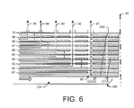
図5および図6は、本明細書で記載することができる半径方向対向流ジェットガス冷却システム230のさらなる実施形態を示す。半径方向対向流ジェットガス冷却システム230は、1つまたは複数の傾斜した半径方向対向流ジェット240を含むことができる。傾斜した半径方向対向流ジェット240は、軸方向サブスロット140を含むことができる。軸方向サブスロット140は、1つまたは複数の傾斜した半径方向対向流ダクト250に通じることができる。傾斜した半径方向対向流ダクト250は、ガスギャップの方向にセンタリングピン40に向かって傾斜していてもよい。その結果、冷却ガス55のうちのより多くをセンタリングピン40の端部に向けて導くことができる。図5は、単一の傾斜した半径方向対向流ダクト250の使用を示す。図6は、2つ以上の傾斜した半径方向対向流ダクト250の使用を示す。任意の数の傾斜した半径方向対向流ダクト250を、本明細書では、任意の適切なサイズ、形状、または構成で使用することができる。他の部品および他の構成を本出願で用いることができる。
5 and 6 illustrate further embodiments of radially counterflow jet
図7は、本明細書で記載することができる半径方向対向流ジェットガス冷却システム260のさらなる実施形態を示す。半径方向対向流ジェットガス冷却システム260は、専用の半径方向対向流ジェット270を含むことができる。専用の半径方向対向流ジェット270は、軸方向サブスロット140および半径方向対向流ダクト150を使用することができる。専用の半径方向対向流ジェット270はまた、専用の半径方向出口ダクト280を含むことができる。専用の半径方向出口ダクト280は、冷却ガス55のための追加の出口経路を提供することができる。専用の半径方向出口ダクト280は、任意の適切なサイズ、形状、または構成を有することができる。他の部品および他の構成も本出願で用いることができる。
FIG. 7 illustrates a further embodiment of a radially counterflow jet
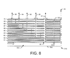
図8は、本明細書で記載することができる半径方向対向流ジェットガス冷却システム290のさらなる実施形態を示す。上記の図2に示したように、軸方向サブスロット140は、センタリングピン40のいずれかの側の半径方向対向流ダクト150の周りで終わっている。図8の例では、半径方向対向流ジェットガス冷却システム290は、連続した軸方向サブスロット300を使用することができる。連続した軸方向サブスロット300は、センタリング・ピン・サブスロット開口部310を通って延在することができる。したがって、サブスロット開口部310は、冷却ガス55がセンタリングピン40のいずれかの側に延在することを可能にする。連続した軸方向サブスロット300は、任意の適切なサイズ、形状、または構成を有することができる。他の部品および他の構成を本出願で用いることができる。
FIG. 8 illustrates a further embodiment of a radially counterflow jet
したがって、本明細書に記載する半径方向対向流ジェットガス冷却システムは、センタリングピン40の周りの温度を大幅に低下させることができるので、その周りのホットスポットを低減または除去することができる。このような能動的な冷却は、ホットスポットを最適な冷却流で低減することができる。上述した半径方向対向流ジェットガス冷却システムの各々は、図示したように、および/または他の実施形態と組み合わせて使用することができる。
Accordingly, the radially counterflow jet gas cooling system described herein can significantly reduce the temperature around the centering
上記は、本出願およびその結果として得られる特許の特定の実施形態のみに関するものであることは明らかである。以下の請求項およびその等価物によって定義されるような本発明の一般的な趣旨および範囲を逸脱することなく、当業者は本明細書において多くの変更および修正を行うことができる。 It is clear that the foregoing relates only to certain embodiments of the present application and the resulting patent. Many changes and modifications can be made herein by those skilled in the art without departing from the general spirit and scope of the invention as defined by the following claims and their equivalents.
20 ロータ
30 導体バー
40 センタリングピン
50 ガス冷却システム
55 冷却ガス
60 軸方向入口ダクト
61 第1の軸方向入口ダクト
62 第2の軸方向入口ダクト
63 第3の軸方向入口ダクト
64 第4の軸方向入口ダクト
69 第9の軸方向入口ダクト
70 第10の軸方向入口ダクト
80 半径方向出口ダクト
81 第1の半径方向出口ダクト
82 第2の半径方向出口ダクト
85 第5の半径方向出口ダクト
90 フローセパレータ
100 ダイナモ電気機械
110 ロータ
120 半径方向対向流ジェットガス冷却システム
130 半径方向対向流ジェット
140 軸方向サブスロット
150 半径方向対向流ダクト
160 半径方向対向流ジェットガス冷却システム
170 半径方向交差冷却ジェット
180 半径方向交差ダクト
190 交差スロット
200 半径方向対向流ジェットガス冷却システム
210 組み合わせた半径方向対向流および交差冷却ジェット
220 半径方向組み合わせダクト
230 半径方向対向流ジェットガス冷却システム
240 傾斜した半径方向対向流ジェット
250 傾斜した半径方向対向流ダクト
260 半径方向対向流ジェットガス冷却システム
270 専用の半径方向対向流ジェット
280 専用の半径方向出口ダクト
290 半径方向対向流ジェットガス冷却システム
300 連続した軸方向サブスロット
310 センタリング・ピン・サブスロット開口部
20
Claims (12)
センタリングピン(40)と、
複数の軸方向入口ダクト(60)と、
前記複数の軸方向入口ダクト(60)と連通する複数の半径方向出口ダクト(80)と、
前記複数の軸方向入口ダクト(60)の周りに配置された軸方向サブスロット(140)と、
前記軸方向サブスロット(140)と連通し、前記センタリングピン(40)に沿って延在する半径方向対向流ダクト(150)と
を含んでおり、前記半径方向対向流ダクト(150)が半径方向交差ダクト(180)を含み、前記センタリングピン(40)が前記半径方向交差ダクト(180)と連通する複数の交差スロット(190)を含む、半径方向対向流ジェットガス冷却システム(120、160、200、230、260、290)。 A radially opposed jet gas cooling system (120, 160, 200, 230, 260, 290) for a rotor (20, 110) of a dynamoelectric machine (100), said radially opposed jet gas cooling system (120, 160, 200, 230, 260, 290) is
a centering pin (40);
a plurality of axial inlet ducts (60);
a plurality of radial outlet ducts (80) communicating with the plurality of axial inlet ducts (60);
axial sub-slots (140) arranged around the plurality of axial inlet ducts (60);
a radial counterflow duct (150) in communication with said axial subslot (140) and extending along said centering pin (40) , said radial counterflow duct (150) radially A radially counterflow jet gas cooling system (120, 160, 200 ) comprising a cross duct (180), said centering pin (40) comprising a plurality of cross slots (190) communicating with said radial cross duct (180). , 230, 260, 290).
センタリングピン(40)と、
複数の軸方向入口ダクト(60)と、
前記複数の軸方向入口ダクト(60)内に配置された1つ又は複数のフローセパレータ(90)と、
前記複数の軸方向入口ダクト(60)と連通する複数の半径方向出口ダクト(80)と、
前記複数の軸方向入口ダクト(60)の周りに配置された軸方向サブスロット(140)と、
前記軸方向サブスロット(140)と連通し、前記センタリングピン(40)に沿って延在し、前記複数の軸方向入口ダクト(60)と連通する半径方向対向流ダクト(150)と
を含んでおり、前記半径方向対向流ダクト(150)が半径方向交差ダクト(180)を含み、前記センタリングピン(40)が前記半径方向交差ダクト(180)と連通する複数の交差スロット(190)を含む、ロータ(20、110)。 A rotor (20, 110) of a dynamoelectric machine (100), the rotor (20, 110) comprising:
a centering pin (40);
a plurality of axial inlet ducts (60);
one or more flow separators (90) positioned within the plurality of axial inlet ducts (60);
a plurality of radial outlet ducts (80) communicating with the plurality of axial inlet ducts (60);
axial sub-slots (140) arranged around the plurality of axial inlet ducts (60);
a radial counterflow duct (150) in communication with said axial sub-slot (140), extending along said centering pin (40) and in communication with said plurality of axial inlet ducts (60) ; said radially counterflow duct (150) comprising a radial cross duct (180) and said centering pin (40) comprising a plurality of cross slots (190) communicating with said radial cross duct (180); a rotor (20, 110);
Applications Claiming Priority (2)
| Application Number | Priority Date | Filing Date | Title |
|---|---|---|---|
| US15/298,453 | 2016-10-20 | ||
| US15/298,453 US10326335B2 (en) | 2016-10-20 | 2016-10-20 | Radial counter flow jet cooling system |
Publications (2)
| Publication Number | Publication Date |
|---|---|
| JP2018099018A JP2018099018A (en) | 2018-06-21 |
| JP7106260B2 true JP7106260B2 (en) | 2022-07-26 |
Family
ID=60143620
Family Applications (1)
| Application Number | Title | Priority Date | Filing Date |
|---|---|---|---|
| JP2017196507A Active JP7106260B2 (en) | 2016-10-20 | 2017-10-10 | Radial counterflow jet cooling system |
Country Status (4)
| Country | Link |
|---|---|
| US (2) | US10326335B2 (en) |
| EP (1) | EP3312974B1 (en) |
| JP (1) | JP7106260B2 (en) |
| CN (1) | CN107968506B (en) |
Families Citing this family (2)
| Publication number | Priority date | Publication date | Assignee | Title |
|---|---|---|---|---|
| US10326335B2 (en) * | 2016-10-20 | 2019-06-18 | General Electric Technology Gmbh | Radial counter flow jet cooling system |
| EP4106152A1 (en) | 2021-06-17 | 2022-12-21 | General Electric Company | Magnetic mass for a rotor, associated rotor and rotating electric machine |
Citations (1)
| Publication number | Priority date | Publication date | Assignee | Title |
|---|---|---|---|---|
| JP2015112006A (en) | 2013-12-05 | 2015-06-18 | ゼネラル・エレクトリック・カンパニイ | Rotor with cooling manifolds |
Family Cites Families (18)
| Publication number | Priority date | Publication date | Assignee | Title |
|---|---|---|---|---|
| BE534929A (en) * | 1954-01-19 | |||
| JPS50146005U (en) | 1974-05-21 | 1975-12-03 | ||
| JPS56118564U (en) * | 1980-02-12 | 1981-09-10 | ||
| BR8503683A (en) | 1984-08-27 | 1986-05-06 | Bbc Brown Boveri & Cie | ROTOR OF AN ELECTRIC MACHINE |
| JPS634140U (en) * | 1986-06-23 | 1988-01-12 | ||
| DE4337628A1 (en) * | 1993-11-04 | 1995-05-11 | Abb Management Ag | Rotor of a turbogenerator with direct gas cooling of the field winding |
| GB2393584B (en) * | 2002-09-26 | 2006-06-21 | Alstom | Gas-cooled generator |
| GB2399231A (en) | 2003-03-07 | 2004-09-08 | Alstom | Multi-path cooling of a turbo-generator rotor winding |
| US7462962B2 (en) | 2005-06-13 | 2008-12-09 | General Electric Company | Cooling system for an electrical machine with center rotor cooling dusts |
| EP1997209B1 (en) | 2006-02-17 | 2011-12-14 | Ansaldo Energia S.P.A. | Ventilated rotor of a high-power turbogenerator for the production of electricity |
| EP2120314A1 (en) | 2008-05-16 | 2009-11-18 | Siemens Aktiengesellschaft | Rotor cooling for dynamoelectric machine |
| US7816825B2 (en) * | 2008-07-23 | 2010-10-19 | General Electric Company | Heat transfer enhancement of ventilation chimneys for dynamoelectric machine rotors |
| US7791230B2 (en) | 2008-10-21 | 2010-09-07 | General Electric Company | Heat transfer enhancement of dynamoelectric machine rotors |
| US8049379B2 (en) * | 2009-04-23 | 2011-11-01 | General Electric Company | Dynamoelectric machine rotors having enhanced heat transfer and method therefor |
| US7893576B2 (en) | 2009-05-05 | 2011-02-22 | General Electric Company | Generator coil cooling baffles |
| US20120101768A1 (en) | 2010-10-26 | 2012-04-26 | General Electric Company | Diagnosis of stator thermal anomalies in an electrical machine |
| EP2768120A1 (en) | 2013-02-15 | 2014-08-20 | Alstom Technology Ltd | Rotor of an electric machine |
| US10326335B2 (en) * | 2016-10-20 | 2019-06-18 | General Electric Technology Gmbh | Radial counter flow jet cooling system |
-
2016
- 2016-10-20 US US15/298,453 patent/US10326335B2/en active Active
-
2017
- 2017-10-10 JP JP2017196507A patent/JP7106260B2/en active Active
- 2017-10-19 EP EP17197337.3A patent/EP3312974B1/en active Active
- 2017-10-20 CN CN201710983892.5A patent/CN107968506B/en active Active
-
2019
- 2019-04-30 US US16/398,424 patent/US11349373B2/en active Active
Patent Citations (1)
| Publication number | Priority date | Publication date | Assignee | Title |
|---|---|---|---|---|
| JP2015112006A (en) | 2013-12-05 | 2015-06-18 | ゼネラル・エレクトリック・カンパニイ | Rotor with cooling manifolds |
Also Published As
| Publication number | Publication date |
|---|---|
| CN107968506B (en) | 2022-03-29 |
| CN107968506A (en) | 2018-04-27 |
| US20180115218A1 (en) | 2018-04-26 |
| EP3312974B1 (en) | 2021-09-01 |
| US11349373B2 (en) | 2022-05-31 |
| JP2018099018A (en) | 2018-06-21 |
| US10326335B2 (en) | 2019-06-18 |
| US20190260268A1 (en) | 2019-08-22 |
| EP3312974A1 (en) | 2018-04-25 |
Similar Documents
| Publication | Publication Date | Title |
|---|---|---|
| US3597645A (en) | Liquid cooling system for stacks of stator laminations of electrical machinery | |
| US9941762B2 (en) | Stator of rotating electric machine | |
| US9660505B2 (en) | Electrical machine with reduced windage loss | |
| EP3016248B1 (en) | Cooling system for electric rotor machine | |
| KR101694542B1 (en) | Generator coil cooling baffles | |
| US9225208B2 (en) | Internal cooling of magnetic core for electric machine | |
| EP3086444B1 (en) | Rotating electric machine | |
| EP3174180B1 (en) | Rotating electric machine | |
| JP7106260B2 (en) | Radial counterflow jet cooling system | |
| US20160020673A1 (en) | Rotor cooling | |
| US20160226325A1 (en) | Cooling device for an electric machine and electric machine comprising a cooling device | |
| CZ330398A3 (en) | Rotor winding for electric machine | |
| JP2019161752A (en) | Rotary electric machine stator | |
| RU2146410C1 (en) | Device with set of winding bars stretched over longitudinal axis and piled up along vertical axis | |
| JP2013034332A (en) | Rotary electric machine | |
| EP4084300A1 (en) | Cooling channels in a high-density motor | |
| US20240055952A1 (en) | Stator, method for simulation, computer program product | |
| US10128717B2 (en) | Ring for an electric machine | |
| JP2010028923A (en) | Rotary electric machine | |
| JP5330860B2 (en) | Rotating electric machine | |
| JP6878129B2 (en) | Rotor of rotating electric machine | |
| US1857023A (en) | Dynamo electric machine | |
| JP2018102018A (en) | Rotor of rotary electric machine | |
| CN115315882A (en) | Stator and rotating electrical machine | |
| US11909262B2 (en) | Thermal management for generator/ motor stators |
Legal Events
| Date | Code | Title | Description |
|---|---|---|---|
| RD04 | Notification of resignation of power of attorney |
Free format text: JAPANESE INTERMEDIATE CODE: A7424 Effective date: 20190527 |
|
| A621 | Written request for application examination |
Free format text: JAPANESE INTERMEDIATE CODE: A621 Effective date: 20201001 |
|
| A977 | Report on retrieval |
Free format text: JAPANESE INTERMEDIATE CODE: A971007 Effective date: 20211022 |
|
| A131 | Notification of reasons for refusal |
Free format text: JAPANESE INTERMEDIATE CODE: A131 Effective date: 20211109 |
|
| A521 | Request for written amendment filed |
Free format text: JAPANESE INTERMEDIATE CODE: A523 Effective date: 20220207 |
|
| TRDD | Decision of grant or rejection written | ||
| A01 | Written decision to grant a patent or to grant a registration (utility model) |
Free format text: JAPANESE INTERMEDIATE CODE: A01 Effective date: 20220615 |
|
| A61 | First payment of annual fees (during grant procedure) |
Free format text: JAPANESE INTERMEDIATE CODE: A61 Effective date: 20220713 |
|
| R150 | Certificate of patent or registration of utility model |
Ref document number: 7106260 Country of ref document: JP Free format text: JAPANESE INTERMEDIATE CODE: R150 |