JP7106060B2 - keyboard instrument - Google Patents
keyboard instrument Download PDFInfo
- Publication number
- JP7106060B2 JP7106060B2 JP2020184949A JP2020184949A JP7106060B2 JP 7106060 B2 JP7106060 B2 JP 7106060B2 JP 2020184949 A JP2020184949 A JP 2020184949A JP 2020184949 A JP2020184949 A JP 2020184949A JP 7106060 B2 JP7106060 B2 JP 7106060B2
- Authority
- JP
- Japan
- Prior art keywords
- hammer
- lower case
- key
- keyboard
- housing
- Prior art date
- Legal status (The legal status is an assumption and is not a legal conclusion. Google has not performed a legal analysis and makes no representation as to the accuracy of the status listed.)
- Active
Links
Images


Description
この発明は、電子ピアノ等の鍵盤装置を備えた鍵盤楽器に関する。 The present invention relates to a keyboard instrument such as an electronic piano having a keyboard device.
従来、電子ピアノ等の電子鍵盤楽器においては、楽器本体の筐体強度を向上させるため、様々な補強方法が適用されている。例えば特許文献1には、電子鍵盤楽器の音響特性を向上させるための整音体(吸音体)を保持するための機能と筐体を補強するための機能とを兼ねた複数の垂下部が、筐体の側壁面に沿って配置されているとともに、各垂下部が接続リブを介して筐体の側壁面に連接された筐体構造が記載されている。 2. Description of the Related Art Conventionally, in electronic keyboard instruments such as electronic pianos, various reinforcement methods have been applied in order to improve the housing strength of the instrument body. For example, in Patent Document 1, a plurality of drooping parts having a function of holding a voicing body (sound absorbing body) for improving the acoustic characteristics of an electronic keyboard instrument and a function of reinforcing a housing are provided. A housing structure is described that is arranged along the side wall surface of the housing and each hanging part is connected to the side wall surface of the housing via a connecting rib.
上述した第1の実施形態に記載された筐体構造においては、筐体の側壁面の周辺の強度を向上させるためには有効であるが、次のような課題を有している。すなわち、電子鍵盤楽器は、複数の鍵盤が配列された鍵盤ユニットを有しているため、必然的に鍵の配列方向に長い筐体を有することになる。このような筐体を有する電子鍵盤楽器において、小型化や軽量化を実現するために筐体部材の肉厚を薄く設計すると、筐体の長手方向の強度が低下して撓みや捻れ等の変形が生じやすくなり、楽器本体が破損しやすくなったり、楽器の操作性や音響特性が劣化したりする可能性がある。そのため、このような問題をより効果的に解決するための筐体構造が求められている。 The housing structure described in the first embodiment described above is effective in improving the strength around the sidewall surface of the housing, but has the following problems. That is, since an electronic keyboard instrument has a keyboard unit in which a plurality of keyboards are arranged, it inevitably has a housing elongated in the direction in which the keys are arranged. In an electronic keyboard instrument having such a housing, if the thickness of the housing member is designed to be thin in order to reduce the size and weight, the strength in the longitudinal direction of the housing will decrease, resulting in deformation such as bending and twisting. This can easily cause damage to the main body of the musical instrument, and can deteriorate the operability and acoustic characteristics of the musical instrument. Therefore, there is a demand for a housing structure that more effectively solves such problems.
そこで、本発明は、筐体強度を効果的に向上させて、小型軽量化することができる鍵盤楽器を提供することを目的とする。 SUMMARY OF THE INVENTION Accordingly, it is an object of the present invention to provide a keyboard instrument that can be reduced in size and weight by effectively improving the strength of the housing.
本発明に係る鍵盤楽器は、一端側に設けられ、押鍵時に押し下げられる力点部と、他端側に設けられ、押鍵される鍵に対して荷重を加える錘部と、前記力点部と前記錘部の間に設けられている支点部と、を有する複数のハンマー部材と、押鍵時に前記支点部を中心に前記ハンマー部材が上下方向に揺動するように、前記複数のハンマー部材を保持している保持部材、が設けられている下部ケースと、前記下部ケースから上方向に延びるとともに前記鍵の長手方向に延びるリブ形状の補強部材と、を備え、前記補強部材は、隣接する2つの前記ハンマー部材の間隙に設けられ、各ハンマー部材が前記支点部を中心に前記鍵の配列方向に揺動した場合であっても前記錘部が当接しないように、前記錘部に対応する部分が他の部分よりも低くなっていることを特徴とする。 A keyboard instrument according to the present invention is provided at one end of a keyboard instrument to be pressed down when a key is pressed; and a fulcrum portion provided between the weight portions, and the plurality of hammer members are arranged so that the hammer members swing vertically around the fulcrum portion when a key is depressed. and a rib-shaped reinforcing member extending upwardly from the lower case and extending in the longitudinal direction of the key, the reinforcing member comprising two adjacent keys. provided in the gap between the two hammer members and corresponding to the weights so that the weights do not come into contact with each other even when the hammers swing about the fulcrums in the arrangement direction of the keys. Part is lower than other parts.
この発明によれば、鍵盤楽器の筐体強度を効果的に向上させて、小型軽量化することができる。 According to the present invention, it is possible to effectively improve the housing strength of the keyboard instrument and reduce the size and weight.
以下、本発明を実施するための形態について、図面を参照しながら詳しく説明する。
(鍵盤楽器)
図1は、本発明に係る鍵盤楽器の一実施形態を示す外観図である。また、図2は、本実施形態に係る鍵盤楽器の構造例を示す概略組み付け図である。ここでは、鍵盤楽器の一例として電子ピアノを示して説明するが、特定方向を長手方向として延在する筐体を有し、ユーザ(演奏者)の押鍵操作に応じて楽音を発音するものであれば他の電子楽器であってもよい。
EMBODIMENT OF THE INVENTION Hereinafter, the form for implementing this invention is demonstrated in detail, referring drawings.
(keyboard instrument)
FIG. 1 is an external view showing an embodiment of a keyboard instrument according to the present invention. FIG. 2 is a schematic assembly diagram showing a structural example of the keyboard instrument according to this embodiment. Here, an electronic piano will be described as an example of a keyboard instrument, but it has a housing extending in a specific direction as its longitudinal direction, and produces musical tones in accordance with the user's (performer's) key-pressing operations. Any other electronic musical instrument may be used.
本発明に係る鍵盤楽器は、例えば図1(a)、(b)に示すように、電子ピアノの楽器本体100と、楽器本体100が載置されて固定されるスタンド200とを有している。ここで、楽器本体100は、スタンド200上面の特定の位置に載置するために、例えば図1(b)に示すように、スタンド200側に設けられた位置決め凸部202に嵌合する位置決め凹部(詳しくは後述する)が下面側に設けられている。スタンド200上面に位置決めされた楽器本体100は、ネジやボルト等の締結部品(図示を省略)によりスタンド200上面に締結固定される。
1A and 1B, the keyboard instrument according to the present invention includes an
楽器本体100は、例えば図1、図2に示すように、概略、鍵盤ユニット120と、上ケース140と、下ケース160とを有している。鍵盤ユニット120は、ユーザ側となる前方側(図面手前側)に演奏操作子としての複数の鍵を有し、ユーザが押鍵操作を行うことにより音高が指定される。
The musical instrument
上ケース140は、鍵盤ユニット120の各鍵が露出する開口部142を備えた枠体を有し、開口部142の後方側(図面奥側)の上面には、音量調整や音色選択等の操作を行うためのスイッチ類や、演奏中の楽曲に関する情報や各種の設定情報等を表示するための表示パネル等を備えた操作パネル144が配置されている。また、上ケース140には、ユーザによる押鍵操作により指定された音高に応じた楽音を生成する音源回路基板146や、生成された楽音を発音するスピーカ148等が組み込まれている。下ケース160は、内面側(図面上面側)に鍵盤ユニット120及び上ケース140が組み付けられ、外面側(図面下面側)にはスタンド200への載置、固定を行うための位置決め凹部やネジ穴が設けられている。
The
鍵盤ユニット120は、図1、図2に示すように、楽器本体100の長手方向(図面左右方向)に複数の白鍵122及び黒鍵124が所定の順序で規則的に配列されている。ここでは、鍵盤ユニット120は、合計88個の白鍵122及び黒鍵124が配列されている。これらの白鍵122及び黒鍵124は、個別に上下方向に回動可能に共通の鍵盤シャーシ126に取り付けられている。鍵盤ユニット120は、上ケース140の開口部142から露出した前方側(図面手前側)の鍵盤部分がユーザによる押鍵操作が行われる領域となり、後方側(図面奥側)は上ケース140の内部に収納される。なお、本願明細書においては、「鍵」と記載した場合には、特に言及しない限り白鍵及び黒鍵に共通する事項を指す。
As shown in FIGS. 1 and 2, the
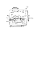
図3は、本実施形態に係る鍵盤楽器に適用される下ケースを示す概略図である。図3(a)は下ケースの外面側を示す図であり、図3(b)は下ケースの内面側を示す図である。ここで、下ケースの外面側は、図1、図2に示した楽器本体100の下面側に対応し、下ケースの内面側は、楽器本体100の内部側、又は、図2に示した下ケース160の上面側に対応する。
FIG. 3 is a schematic diagram showing a lower case applied to the keyboard instrument according to this embodiment. FIG. 3(a) is a diagram showing the outer surface side of the lower case, and FIG. 3(b) is a diagram showing the inner surface side of the lower case. Here, the outer surface side of the lower case corresponds to the lower surface side of the
本実施形態においては、鍵盤楽器の筐体強度を向上させるために、図3に示すように、下ケース160に異なる種類の複数の筐体補強部310~340が設けられている。いずれの筐体補強部310~340も、楽器本体100又は下ケース160の長手方向、及び、当該長手方向に直交する楽器本体100又は下ケース160の短手方向に、板状部材からなる複数のリブが設けられている。ここで、楽器本体100又は下ケース160の長手方向は、図2、図3に示すように、鍵盤ユニット120の鍵の配列方向に対応し、楽器本体100又は下ケース160の短手方向は、図2に示すように、鍵の配列方向に直交し、鍵盤ユニット120の鍵の上面が延在する鍵の長手方向に対応する。
In this embodiment, in order to improve the strength of the housing of the keyboard instrument, as shown in FIG. Each of the
以下、各筐体補強部310~340について、具体的に説明する。
(1)第1の筐体補強部310
図4は、本実施形態に係る鍵盤楽器に適用される第1の筐体補強部を示す要部斜視図であり、図5は、本実施形態に係る第1の筐体補強部を適用した楽器本体を示す要部断面図である。なお、図5においては、図示の都合上、上ケースを省略した断面を示す。
Each of the
(1) First
FIG. 4 is a perspective view of a main part showing the first housing reinforcing section applied to the keyboard instrument according to the present embodiment, and FIG. FIG. 2 is a cross-sectional view of a main part showing a musical instrument body; Note that FIG. 5 shows a cross section with the upper case omitted for convenience of illustration.
第1の筐体補強部310は、具体的には、図3(a)に示すように、下ケース160の外面側の、下ケース160の長手方向に延在する領域(第1領域)に、連続する溝部312が設けられている。溝部312は、図4、図5に示すように、下ケース160の外面側から楽器本体100の内部(下ケース160の内面側)方向に窪んだ凹部を有し、溝部312の内部に、下ケース160の長手方向に延在する複数条の板状部材を有するリブ314と、長手方向に直交する下ケース160の短手方向に延在する複数条の板状部材を有するリブ316と、が格子状に配置されている。ここで、リブ314、316は、図4、図5に示すように、溝部312の深さと略同等の高さを有して、溝部312内に一体的に設けられている。
Specifically, as shown in FIG. 3( a ), the first
このように、下ケース160の長手方向に連続する溝部312、及び、その内部に格子状に配置されたリブ314、316を設けることにより、楽器本体100の小型軽量化のために各部材の肉厚を薄く設計した場合であっても、下ケース160や下ケース160を含む楽器本体100の長手方向に対して垂直方向に生じる変形(撓み)を抑制することができ、筐体の強度を向上させることができる。また、下ケース160の短手方向に溝部312の幅を広くするとともに、当該幅に応じてリブ316を長く形成することにより、下ケース160や楽器本体100の長手方向を軸として回転方向に生じる変形(捻れ)を抑制することもでき、筐体の強度をさらに向上させることができる。
Thus, by providing the
また、第1の筐体補強部310は、図4に示すように、下ケース160の溝部312内に、楽器本体100をスタンド200上面の特定の位置に載置するための位置決め部が設けられている。例えば図1に示したように、スタンド側に位置決め凸部202が設けられた形態においては、下ケース160の外面側に設けられた溝部312内に、スタンド200上面の位置決め凸部202が嵌合する位置決め凹部318が設けられている。位置決め凹部318は、下ケース160の長手方向に延在する溝部312の両端部近傍に複数箇所設けられる。ここで、位置決め凹部318は、スタンド側の位置決め凸部202の形状や高さ等に対応するように、溝部312内のリブ314、316の配置や形状、高さ等を設定することにより形成される。例えば、スタンド200側の位置決め凸部202が円柱状である場合には、図4に示すように、位置決め凹部318として、円柱状の位置決め凸部202が嵌合する部分のリブ314、316が除去されるとともに、位置決め凸部202の円柱外周面に係合するように円弧状の支持リブ(支持部)319が設けられる。
Further, as shown in FIG. 4, the first
これにより、楽器本体100をスタンド200上に載置、固定する際に、溝部312内に設けられた位置決め凹部318により簡易かつ確実に位置決めを行うことができる。ここで、溝部312内には格子状のリブ314、316が設けられていることにより、下ケース160の強度を向上させているので、下ケース160や楽器本体100の変形に伴う位置決め凹部318の位置の変化やずれを抑制することができ、楽器本体100をスタンド200の特定の位置に簡易かつ確実に載置、固定することができる。
As a result, when the
また、第1の筐体補強部310は、図5に示すように、溝部312が下ケース160の外面側から楽器本体100の内部方向に窪むように設けられているため、楽器本体100の内部(下ケース160の内面側)に溝部312の形状に対応した突出部(凸部)が形成される。本実施形態においては、この突出部の図面上面に対して、鍵盤ユニット120において各鍵に対応して設けられるハンマー部材422を回動可能に支持するハンマーホルダ(保持部材)426の図面下方側の端部が載置されるように、突出部(溝部312)やハンマーホルダ426の形状や寸法が設定されている。ここで、突出部(溝部312)にハンマーホルダ426が載置された状態でネジ等の締結部材により双方を締結固定することにより、ハンマーホルダ426を含む鍵盤ユニット120が下ケース160に組み付けられる。
Further, as shown in FIG. 5, the first
これにより、下ケース160に鍵盤ユニット120を組み付けた際に、溝部312に対応した突出部によりハンマーホルダ426を下方から支持することができる。ここで、溝部312内に設けられた格子状のリブ314、316により、下ケース160の強度を向上させているので、鍵盤ユニット120の重みや、押鍵時の衝撃や押圧力による下ケース160や楽器本体100の変形を抑制することができる。また、突出部(溝部312)とハンマーホルダ426とが締結固定されているので、押鍵時のハンマー部材の回動に伴う異音や振動の発生を抑制することができる。なお、鍵盤ユニット120の詳細な鍵盤機構については後述する。
As a result, when the
なお、本実施形態においては、溝部312内に四角形の空間を有する格子状にリブ314、316を配置した形態を示したが、本発明はこれに限定されるものではない。第1の筐体補強部310のリブは、下ケース160の長手方向及び短手方向の両方向に対して筐体の強度を高められる構造を有しているものであればよく、他の補強構造として、例えば溝部312内に三角形の空間を有するトラス状や六角形の空間を有するハニカム状にリブ314、316を配置した形態を適用するものであってもよい。
In this embodiment, the
また、本実施形態においては、第1の筐体補強部310として、下ケース160の外面側から楽器本体100の内部方向に窪んだ凹部を有する溝部312を設け、溝部312内に格子状にリブ314、316を配置した形態を示したが、本発明はこれに限定されるものではない。第1の筐体補強部310として、溝部312を設けることなく、下ケース160の内面側(楽器本体100の内部側)の、上記溝部312が設けられる領域に対応する領域(第1領域)に格子状に配置されたリブが突出し、下ケース160の長手方向に沿って延在しているものであってもよい。この形態においても、上述した実施形態と同様に、下ケース160の強度を向上させることができる。ここで、格子状に配置されたリブの長手方向及び短手方向の端部は、リブの外周を囲むように配置された枠状のリブにより連結されているものであってもよい。これによれば、枠状のリブが上述した実施形態に示した溝部312の側壁面と同等の機能を有し、筐体の強度をさらに向上させることができる。
In this embodiment, as the first
(2)第2の筐体補強部320
図6は、本実施形態に係る鍵盤楽器に適用される第2の筐体補強部を示す要部平面図であり、図7、図8は、本実施形態に係る第2の筐体補強部を適用した楽器本体の鍵盤機構を示す要部断面図である。なお、図7、図8においては、図示の都合上、上ケースを省略した断面を示す。図9は、本実施形態に係る鍵盤楽器に適用される第2の筐体補強部のリブとハンマー部材との干渉状態の一例を示す図である。図10は、本実施形態に係る鍵盤楽器に適用される第2の筐体補強部のリブの配置間隔の一例を示す平面図である。
(2) Second
FIG. 6 is a plan view of the main part showing the second housing reinforcing section applied to the keyboard instrument according to the present embodiment, and FIGS. 7 and 8 are the second housing reinforcing section according to the present embodiment. 1 is a cross-sectional view of a main part showing a keyboard mechanism of a musical instrument body to which is applied. 7 and 8, for convenience of illustration, the cross section is shown with the upper case omitted. FIG. 9 is a diagram showing an example of an interference state between the rib of the second housing reinforcing portion and the hammer member applied to the keyboard instrument according to the present embodiment. FIG. 10 is a plan view showing an example of an arrangement interval of ribs of the second housing reinforcing portion applied to the keyboard instrument according to the present embodiment.
第2の筐体補強部320は、具体的には、図3(b)、図6に示すように、下ケース160の内面側において、鍵盤ユニット120に配列された白鍵122及び黒鍵124のそれぞれに対応して設けられたハンマー部材422相互の間隙に対応する領域に、下ケース160の短手方向に延在する1又は複数条の板状部材を有するリブ(補強部材)322が配置されている。また、第2の筐体補強部320には、下ケース160の短手方向に直交する下ケース160の長手方向に延在し、短手方向に延在する複数のリブ322を相互に連結するリブ324が配置されている。本実施形態においては、図6、図7に示すように、下ケース160の短手方向に延在するリブ322の一端側(図6下方端側、図7左方端側)が、上述した第1の筐体補強部310に設けられる溝部312の形状に対応して下ケース160の内面側に突出し、長手方向に延在する突出部の側壁面に接続されている。すなわち、1又は複数のリブ322は、下ケース160の溝部312が設けられた領域(第1領域)に隣接する領域(第2領域)に設けられ、当該溝部312に対応する突出部の側壁面がリブ324としての機能を有し、複数のリブ322相互が長手方向に連結される。
Specifically, as shown in FIGS. 3B and 6, the second
ここで、第2の筐体補強部320について詳しく説明するために、本実施形態に適用される鍵盤ユニットの鍵盤機構について説明する。ここでは、白鍵122の鍵盤機構について説明するが、黒鍵124についても同様の鍵盤機構を有している。
Here, in order to describe the second
鍵盤ユニットの鍵盤機構は、図7に示すように、白鍵122及び黒鍵124が上下方向に回動可能に取り付けられた共通の鍵盤シャーシ126と、鍵盤シャーシ126に取り付けられた白鍵122及び黒鍵124のそれぞれに対する押鍵操作に伴ってアクション荷重を付与するためのハンマーユニット420と、白鍵122及び黒鍵124に対する押鍵操作に応じてオン動作するスイッチ部410と、を備えている。
The keyboard mechanism of the keyboard unit, as shown in FIG. A
楽器本体100に対してユーザ側となる、鍵盤シャーシ126の前方側の端部(図面左方側端部)には、図面上方の白鍵122に向かって突出する前脚部402が設けられている。前脚部402の上部には、各白鍵122の回動時に鍵の配列方向(図の紙面に垂直方向)への横振れを防止するための鍵ガイド部404が設けられ、前脚部402の前方側(図面左方側)には、白鍵122の回動時の上限位置及び下限位置を規制するためのストッパ部406が設けられている。また、鍵盤シャーシ126の前脚部402の後方側(図面右方側)には、ハンマーユニット420が取り付けられるユニット取付け部408が図面上方に突出して設けられている。
A
また、鍵盤シャーシ126のユニット取付け部408の後方側(図面右方側)には、白鍵122への押鍵操作に応じてオン動作するスイッチ部410を搭載した発音用基板412が取り付けられている。発音用基板412は、複数配列されている白鍵122及び黒鍵124に対して共通に設けられ、発音用基板412上に各白鍵122及び黒鍵124に個別に対応するように複数のスイッチ部410が搭載されている。また、発音用基板412には、白鍵122への押鍵操作に応じてスイッチ部410から出力されるオン信号に基づいて楽音情報を生成する処理回路が搭載されている。
Also, on the rear side (on the right side in the drawing) of the
また、鍵盤シャーシ126の基板取付け部のさらに後方側(図面右方側)には、鍵取付け部414が設けられ、白鍵122の後端部(図面右方側端部)が、白鍵122を上下方向に回動可能に支持する支持軸416を介して鍵取付け部414に取り付けられている。また、鍵盤シャーシ126の後方側の端部(図面右方側端部)には、鍵取付け部414から垂下する後脚部418が設けられている。この後脚部418には、白鍵122への押鍵操作に応じてハンマーユニット420のハンマー部材422が回動する際の上限位置及び下限位置を規制するためのストッパ部419が設けられている。
A
ハンマーユニット420は、図6、図7に示すように、白鍵122及び黒鍵124のそれぞれに対応して設けられ、各鍵への押鍵操作に応じて個別に回動してアクション荷重を付与する複数のハンマー部材422と、複数の白鍵122及び黒鍵124に対して共通に設けられ、各鍵に対応するハンマー部材422を支持軸424を介してそれぞれ回動可能に支持するハンマーホルダ426と、を備えている。ハンマーホルダ426は、図7に示すように、上述した鍵盤シャーシ126のユニット取付け部408の下面側に取り付けられる。
As shown in FIGS. 6 and 7, the
ハンマー部材422は、図7に示すように、金属材料からなるハンマー本体432と、ハンマー本体432の一端側(図7左方端側)に設けられた力点部である鍵連結部434と、ハンマー本体432の他端側(図7右方端側)に設けられた荷重点部である錘部436と、ハンマー本体432の錘部436と鍵連結部434との間に設けられ、ハンマー本体432を回動可能に支持する支持軸424と、を備えている。ここで、ハンマー部材422の錘部436は、図6、図7に示すように、錘部436と支持軸424との間のハンマー本体432に比較して、下ケース160の長手方向(鍵の配列方向)から見た平面形状、及び、下ケース160の長手方向(鍵の配列方向)の厚みが大きくなるように形成されていることにより、鍵に所定のアクション荷重を付与するための重量が設定されている。なお、ハンマー部材422は、白鍵用と黒鍵用とで略同等の形状を有しているが、白鍵122と黒鍵124とでは押鍵操作における打鍵位置や鍵の形状等が異なるため、ハンマー部材422の平面形状や厚み、重さ、支持軸424から錘部436や鍵連結部434までの寸法等が若干異なるように設計されている。
As shown in FIG. 7, the
このような鍵盤構造を有する鍵盤ユニット120を備えた楽器本体100において、ユーザが押鍵操作を行っていない状態(初期状態)においては、図7に示すように、ハンマー部材422が錘部436の重量によって支持軸424を中心に時計回りに回動するように付勢されて、錘部436が鍵盤シャーシ126に設けられた下限ストッパ部419に当接して下限位置が規制される。また、ハンマー部材422の鍵連結部434が鍵を押し上げることにより、鍵を上限位置である初期位置に規制する。
In the
次いで、ユーザが押鍵操作を行った状態においては、図8に示すように、白鍵122又は黒鍵124が支持軸416を中心に反時計回りに回動する。これにより、ハンマー部材422の鍵連結部434が鍵により押し下げられて、ハンマー部材422が支持軸424を中心に反時計回りに回動して錘部436が上昇するとともに、錘部436の重量に基づくアクション荷重が鍵に付与される。そして、押鍵操作に伴ってハンマー部材422の鍵連結部434が鍵によりさらに押し下げられると、ハンマー部材422の錘部436がさらに上昇して鍵盤シャーシ126に設けられた上限ストッパ部419に当接することによりハンマー部材422の回動が停止して上限位置が規制されるとともに、鍵の下限位置が規制される(鍵下限状態)。
Next, when the user performs a key depression operation, the
この押鍵操作において、ハンマー部材422の錘部436が上限ストッパ部419に当接するまでの間に、鍵盤シャーシ126に取り付けられたスイッチ部410が鍵により押圧されてオン動作すると、当該鍵に応じた楽音情報が生成される。この楽音情報に基づいて、上ケース140に組み込まれた音源回路において楽音が生成され、スピーカ148から発音される。その後、ユーザが押鍵操作を終了した場合には、ハンマー部材422が錘部436の重量によって時計回りに回動して、錘部436が下限ストッパ部419に当接して下限位置が規制されるとともに、鍵連結部434が鍵を押し上げて上限位置である初期位置に規制する。このように、ハンマー部材422は、支持軸424を中心に錘部436及び鍵連結部434がそれぞれ上下方向に揺動するように動作する。
In this key depression operation, when the
上述したような鍵盤機構を有する鍵盤ユニットが組み付けられた下ケースにおいて、第2の筐体補強部320は、図6に示すように、白鍵122及び黒鍵124のそれぞれに対応して設けられたハンマー部材422相互の間隙に対応する領域に、下ケース160の短手方向に延在する少なくとも1つのリブ(補強部材)322が配置されている。ここで、リブ322は、下ケース160と同一又は同等の樹脂材料を用いて一体的に成形されている。ハンマー部材422相互の間隙に設けられるリブ322の形状や高さ、厚み寸法は、図7、図8に示したハンマー部材422の回動(上下方向の揺動)時の軌跡や、図9に示すような当該回動時や楽器本体100を縦置きした場合(又は、楽器本体100の長手方向を天地となるように取り扱った場合)の鍵の配列方向への横振れ(長手方向の揺動)の範囲に対して、当接や接触、乗り上げ等の干渉が生じないように設定される。例えば図7、図9(b)に示すように、リブ322の高さ(下ケース160の内面側の突出寸法)が、ユーザ側となる前方側(図面左方側のリブ324との接続部)から後方側(図面右方側)に向かって段階的或いは連続的に低くなる平面形状や、切り欠かれた切り欠き部を有している。
In the lower case in which the keyboard unit having the keyboard mechanism as described above is assembled, the second
これにより、図9(a)に示すように、ハンマー部材422が鍵の配列方向(図面上下方向)へ大きく横振れした場合であっても、ハンマー部材422のハンマー本体432や錘部436が接触する範囲のリブ322の高さが低く設定されているので、ハンマー部材422とリブ322との干渉を回避することができ、ハンマー部材の回動や横振れに伴う異音や振動の発生を抑制することができる。なお、リブ322の平面形状は、ハンマー部材422の回動や横振れに対して干渉しないものであればよく、例えば高さが直線的や曲線的に連続して低くなる平面形状を有しているものであってもよい。
As a result, as shown in FIG. 9(a), even if the
また、リブ322の配置個数やリブ322相互の配置間隔は、筐体の強度を向上させるためには、図6、図7又は図9に示したように、複数のリブ322が下ケース160の長手方向に均一又は略均一に設定されていることが好ましく、また、短手方向に延在する長さは極力長く設定されていることが好ましい。ここで、上述したように、鍵盤楽器においては、白鍵122と黒鍵124の押鍵操作における打鍵位置や鍵の形状等が異なるため、白鍵122及び黒鍵124のそれぞれに対応して設けられるハンマー部材422の平面形状や厚み、重さ等が異なるように設定されている。そのため、白鍵122と黒鍵124とではハンマー部材422の回動時の軌跡や横振れの範囲が異なることになる。そこで、本実施形態においては、図10に示すように、複数のリブ322を下ケース160の長手方向に規則的又は略規則的に配置しつつ、リブ322相互の配置間隔を極力近似させるように設定する。
In order to improve the strength of the housing, the number of
これにより、複数のリブ322を、押鍵時のハンマー部材422の回動軌跡や横振れ範囲に干渉することなく、下ケース160の長手方向に規則的又は略規則的に配置しつつ、短手方向に極力長く延在させることできるので、押鍵時のハンマー部材の回動に伴う異音や振動の発生を抑制しつつ、下ケース160や楽器本体100の短手方向に対して垂直方向に生じる変形(撓み)を抑制することができ、筐体の強度を向上させることができる。
As a result, the plurality of
また、第2の筐体補強部320は、図7、図9(b)に示すように、下ケース160の短手方向に延在する複数のリブ322の高さ(下ケース160の内面側の突出寸法)が最も高くなる前方側(図面左方側)の端部が、上述した第1の筐体補強部310に設けられる溝部312により下ケース160の内面側に突出する突出部の側壁面に接続されている。
Further, as shown in FIGS. 7 and 9B, the second
これにより、突出部の側壁面をリブ324として適用して、複数のリブ322相互が下ケース160の長手方向に連結されることになるので、下ケース160の短手方向に延在するリブ322の強度を向上させることができるとともに、下ケース160や楽器本体100の長手方向に対して垂直方向に生じる変形(撓み)や、長手方向を軸として回転方向に生じる変形(捻れ)を抑制することもでき、筐体の強度をさらに向上させることができる。また、この場合、第1の筐体補強部310の一部の構成(突出部の側壁面)を、第2の筐体補強部320の構成(リブ324)と兼用しているので、楽器本体100内部の部材のレイアウトを省スペース化することができる。
As a result, the side walls of the projecting portion are used as
(3)第3の筐体補強部330
図11は、本実施形態に係る鍵盤楽器に適用される第3の筐体補強部を示す概略斜視図である。図11(a)は、第3の筐体補強部を適用した下ケースを示す全体斜視図であり、図11(b)は、下ケースの外面側を示す要部斜視図である。図12は、本実施形態に係る第3の筐体補強部を適用した楽器本体を示す概略断面図である。なお、図12においては、図示の都合上、上ケースを省略した断面を示す。
(3) Third
FIG. 11 is a schematic perspective view showing a third housing reinforcing section applied to the keyboard instrument according to this embodiment. FIG. 11(a) is an overall perspective view showing a lower case to which the third housing reinforcing portion is applied, and FIG. 11(b) is a perspective view showing the main part of the outer surface side of the lower case. FIG. 12 is a schematic cross-sectional view showing a musical instrument body to which the third housing reinforcing portion according to this embodiment is applied. Note that FIG. 12 shows a cross section with the upper case omitted for convenience of illustration.
第3の筐体補強部330は、具体的には、図3(b)、図11、図12に示すように、鍵盤ユニット120に配列された白鍵122の押鍵位置に対応する短手方向前方側(図3(b)下方側、図11手前側)の領域であって下ケース160の長手方向に延在する領域(第3領域)に、下ケース160の外面側から楽器本体100の内部(下ケース160の内面側)方向に窪んだ凹部を有している。具体的には、例えば、下ケース160の内面側において、下ケース160の長手方向に沿って互いに近接して対向する一対の板状部材を有するリブ332と、一対のリブ332の間及びその外方にあって、長手方向に直交する下ケース160の短手方向に延在して一対のリブ332を相互に連結する板状部材を有するリブ334と、が配置されている。ここで、リブ332、334は、図12に示すように、下ケース160の内面側から図面上方の鍵盤ユニット120の白鍵122に向かって突出して設けられているが、リブ332、334の上端部及び上端部に隣接するリブ334の垂下部と、鍵盤ユニット120の鍵盤シャーシ126との間には間隙が形成されるようにリブ332、334の形状や高さが設定されている。
Specifically, as shown in FIGS. 3(b), 11, and 12, the third
このように、下ケース160の前方側の領域に、長手方向に連続する一対のリブ332、及び、短手方向にリブ332相互を連結するとともに、その外方にまで延在するリブ334を設けることにより、下ケース160や楽器本体100の長手方向に対して垂直方向に生じる変形(撓み)を抑制することができ、筐体の強度を向上させることができる。また、鍵の押鍵位置の直下となる下ケース160の領域に、リブ332、334を鍵盤ユニット120から離間するように突出させることにより、ユーザが押鍵操作を行った場合であっても、その衝撃や押圧力が直接下ケース160に伝達されることがないので、下ケース160や楽器本体100の変形(撓み)を抑制することができるとともに、押鍵時の異音や振動の発生を抑制することができる。
In this manner, a pair of
なお、図3(b)においては、リブ332、334を有する第3の筐体補強部330を、下ケース160の長手方向に2つに分割して配置した例を示した。これは、下ケース160の長手方向の略中央付近に設けられている、楽器本体100の駆動電源となる電池ボックスを回避するために、リブ332、334の配置を分割したものであって、本発明はこれに限定されるものではない。下ケース160におけるレイアウト設計を変更することにより、連続する一つの第3の筐体補強部330を配置するものであってもよいし、2つ以上の複数に分割して配置するものであってもよい。
Note that FIG. 3B shows an example in which the third
また、リブ332、334は、下ケース160に組み付けられる上ケース140や鍵盤ユニット120をネジ等の締結部材で締結固定するための取り付けボスや取り付け穴の近傍に配置することが好ましい。この場合、リブ332、334を取り付けボスと一体的、又は、連結して形成し、上ケース140や鍵盤ユニット120を締結固定することにより、或いは、取り付け穴において上ケース140や鍵盤ユニット120を締結固定することにより、リブ332、334を薄い板状部材により形成した場合であっても筐体の強度を向上させることができるとともに、楽器本体100内部の部材のレイアウトを省スペース化することができる。
Moreover, the
(4)第4の筐体補強部340
図13は、本実施形態に係る鍵盤楽器に適用される第4の筐体補強部を示す概略斜視図である。図13(a)は、第4の筐体補強部を適用した下ケースを示す全体斜視図であり、図13(b)、(c)は、第4の筐体補強部を示す要部斜視図である。図14は、本実施形態に係る第4の筐体補強部を適用した楽器本体を示す概略断面図である。なお、図14においては、図示の都合上、上ケースを省略した断面を示す。図15は、本実施形態に係る第4の筐体補強部を適用した楽器本体内部のケーブル配設例を示す概略図である。図15(a)は、第4の筐体補強部を適用した楽器本体におけるスピーカケーブルの配設例を示す図であり、図15(b)は、比較対象となるスピーカケーブルの配設例を示す図である。
(4) Fourth
FIG. 13 is a schematic perspective view showing a fourth housing reinforcing section applied to the keyboard instrument according to this embodiment. FIG. 13(a) is an overall perspective view showing a lower case to which a fourth housing reinforcement is applied, and FIGS. It is a diagram. FIG. 14 is a schematic cross-sectional view showing a musical instrument body to which the fourth housing reinforcing portion according to this embodiment is applied. Note that FIG. 14 shows a cross section with the upper case omitted for convenience of illustration. FIG. 15 is a schematic diagram showing an example of cable arrangement inside a musical instrument body to which the fourth housing reinforcing portion according to the present embodiment is applied. FIG. 15(a) is a diagram showing an arrangement example of speaker cables in a musical instrument body to which the fourth housing reinforcing portion is applied, and FIG. 15(b) is a diagram showing an arrangement example of speaker cables for comparison. is.
第4の筐体補強部340は、具体的には、図3(b)、図13、図14に示すように、下ケース160の内面側において、楽器本体100の短手方向後方側(図3(b)上方側、図13奥側、図14)の領域であって鍵盤ユニット120の後方側の、下ケース160の長手方向に延在する領域(第4領域)に、互いに近接して対向する一対の板状部材を有するリブ(補強部材)342が配置されている。また、第4の筐体補強部340には、一対のリブ342の間にあって、長手方向に直交する下ケース160の短手方向に延在して一対のリブ342を相互に連結する板状部材を有するリブ344が配置されている。ここで、リブ344は、図13に示すように、リブ342と略同等の高さを有している。また、図13、図14に示すように、リブ344の上端部分には上ケース140に組み込まれ、鍵盤ユニット120の後方側に配置される音源回路基板(回路基板)146とスピーカ(発音部)148との間を接続するスピーカケーブル150を、一対のリブ342間に収納して保持固定するためのU字型やV字型の溝を有するスリット部346が設けられている。また、リブ342、344は、図15(a)に示すように、音源回路基板146とスピーカ148との間に配設されるスピーカケーブル150と、音源回路基板146の配線や電子部品とが平面視して重ならないように、或いは、極端に近接しないように、下ケース160から突出する高さが設定されている。
Specifically, as shown in FIGS. 3(b), 13, and 14, the fourth
このように、下ケースの後方側の領域に、長手方向に連続する一対のリブ342、及び、短手方向にリブ342相互を連結するリブ344を設けることにより、下ケース160や楽器本体100の長手方向に対して垂直方向に生じる変形(撓み)を抑制することができ、筐体の強度を向上させることができる。また、楽器本体100の内部に収納される音源回路基板146とスピーカ148との間に配設されるスピーカケーブル150を、一対のリブ342相互を連結するリブ344に設けられたスリット部346により保持固定して一対のリブ342間に収納することにより、スピーカケーブル150と音源回路基板146との平面的な重なりや近接を回避することができる。
In this way, by providing a pair of
ここで、図15(b)に示すように、スピーカケーブル150が音源回路基板146に対して平面的に重なったり極端に近接したりしている場合には、音源回路基板146からのノイズが混入してスピーカ148から発音される楽音の音質が劣化しやすくなる。これに対して、本実施形態においては、スピーカケーブル150と音源回路基板146との平面的な重なりや近接を極力回避するようにリブ342、344の高さが設定されているので、スピーカ148から発音される楽音へのノイズの混入を抑制して音質を向上させることができる。また、この場合、音源回路基板146に設けられるスピーカケーブル150のコネクタ147の配置を変更することなくノイズの混入を抑制することができるので、既存の回路基板をそのまま使用することができる。
Here, as shown in FIG. 15(b), when the
なお、リブ342は、図13に示すように、下ケース160に組み付けられる上ケース140や鍵盤ユニット120をネジ等の締結部材で締結固定するための取り付けボス350の近傍に配置され、取り付けボス350と一体的、又は、取り付けボス350に連結して形成される。これにより、リブ342、344を薄い板状部材により形成した場合であっても筐体の強度を向上させることができるとともに、楽器本体100内部の部材のレイアウトを省スペース化することができる。
13, the
上述した実施形態においては、本発明に係る異なる種類の複数の筐体補強部について説明したが、本発明に係る電子鍵盤楽器は、これらの全ての筐体補強部を備えるものであってもよいし、いずれか一つの補強部のみを備えるものであってもよいし、任意の筐体補強部の組み合わせを備えるものであってもよい。 In the above-described embodiment, a plurality of housing reinforcing sections of different types according to the present invention have been described, but the electronic keyboard instrument according to the present invention may include all of these housing reinforcing sections. However, it may be provided with only one reinforcing portion, or may be provided with any combination of housing reinforcing portions.
以上、本発明のいくつかの実施形態について説明したが、本発明は、上述した実施形態に限定されるものではなく、特許請求の範囲に記載された発明とその均等の範囲とを含むものである。
以下に、本願出願の当初の特許請求の範囲に記載された発明を付記する。
Although several embodiments of the present invention have been described above, the present invention is not limited to the above-described embodiments, and includes the invention described in the claims and their equivalents.
The invention described in the original claims of the present application is appended below.
(付記)
[1]
一端側に設けられ、押鍵時に押し下げられる力点部と、他端側に設けられ、押鍵される鍵に対して荷重を加える錘部と、前記力点部と前記錘部の間に設けられている支点部と、を有し、押鍵時に前記支点部を中心に上下方向にそれぞれ揺動する複数のハンマー部材と、
前記複数のハンマー部材の間隙に、各ハンマー部材が前記支点部を中心に前記鍵の配列方向に揺動した場合であっても前記錘部が当接しないように設けられている少なくとも1つの補強部材、を有する筺体と、
を備えることを特徴とする鍵盤楽器。
(Appendix)
[1]
A power point portion provided on one end side to be pushed down when a key is pressed, a weight portion provided on the other end side to apply a load to the key being pressed, and a weight portion provided between the power point portion and the weight portion. a plurality of hammer members each having a fulcrum portion and swinging vertically around the fulcrum portion when a key is depressed;
At least one reinforcement provided in the gap between the plurality of hammer members so that the weight portion does not abut even when each hammer member swings about the fulcrum portion in the arrangement direction of the keys. a housing having a member;
A keyboard instrument comprising:
[2]
[1]に記載の鍵盤楽器において、
前記筺体と、前記少なくとも1つの補強部材と、は一体的に成形されており、
前記少なくとも1つの補強部材は、前記各ハンマー部材が前記支点部を中心に前記鍵の配列方向に揺動した場合であっても前記錘部が当接しないように切り欠かれた切り欠き部、を有することを特徴とする鍵盤楽器。
[2]
In the keyboard instrument according to [1],
The housing and the at least one reinforcing member are integrally molded,
the at least one reinforcing member has a cutout portion cut out so that the weight portion does not come into contact with the hammer member even when the hammer member swings around the fulcrum portion in the arrangement direction of the keys; A keyboard instrument characterized by having
[3]
[1]又は[2]に記載の鍵盤楽器において、
前記筐体は、前記鍵の配列方向に沿って、外面側から内部方向に向けて窪んだ凹部が設けられている第1領域、を有し、
前記少なくとも1つの補強部材は、前記第1領域に隣接する第2領域内に設けられていることを特徴とする鍵盤楽器。
[3]
In the keyboard instrument according to [1] or [2],
The housing has a first region provided with a recess that is recessed from the outer surface toward the inside along the direction in which the keys are arranged,
A keyboard instrument, wherein the at least one reinforcing member is provided in a second region adjacent to the first region.
[4]
[3]に記載の鍵盤楽器において、
前記支点部を支持することにより前記複数のハンマー部材を保持する保持部材、を備え、
前記保持部材は、前記第1領域に対応する前記筺体内の凸部に載置されていることを特徴とする鍵盤楽器。
[4]
In the keyboard instrument according to [3],
a holding member that holds the plurality of hammer members by supporting the fulcrum,
A keyboard instrument, wherein the holding member is mounted on a projection in the housing corresponding to the first area.
[5]
[3]又は[4]に記載の鍵盤楽器において、
前記第1領域内に、板状部材が格子状に配置されていることを特徴とする鍵盤楽器。
[5]
In the keyboard instrument according to [3] or [4],
A keyboard instrument, wherein plate-shaped members are arranged in a grid pattern in the first region.
[6]
[3]乃至[5]のいずれかに記載の鍵盤楽器において、
前記筐体は、前記第1領域内に、当該鍵盤楽器を載置するスタンドに位置決めするための位置決め部が設けられていることを特徴とする鍵盤楽器。
[6]
In the keyboard instrument according to any one of [3] to [5],
A keyboard instrument, wherein the housing is provided with a positioning portion for positioning a stand on which the keyboard instrument is placed in the first area.
[7]
[3]乃至[6]のいずれかに記載の鍵盤楽器において、
前記筐体は、前記鍵の配列方向に沿って外面側から内部方向に向けて窪んだ凹部が、押鍵位置に対応する第3領域に設けられていることを特徴とする鍵盤楽器。
[7]
In the keyboard instrument according to any one of [3] to [6],
A keyboard instrument according to claim 1, wherein said housing is provided with a concave portion recessed inwardly from an outer surface side along an arrangement direction of said keys in a third region corresponding to a key depression position.
[8]
[7]に記載の鍵盤楽器において、
前記筐体は、前記鍵の配列方向に沿って延びる他の補強部材が、前記複数の鍵の後方の第4領域に設けられていることを特徴とする鍵盤楽器。
[8]
In the keyboard instrument according to [7],
A keyboard instrument according to claim 1, wherein said housing includes another reinforcing member extending along the direction in which said keys are arranged, provided in a fourth region behind said plurality of keys.
[9]
[8]に記載の鍵盤楽器において、
前記複数の鍵の後方側に、押鍵操作に応じた楽音を生成する回路基板と、前記楽音を発音する発音部と、が配置され、
前記回路基板と前記発音部とを接続するケーブルが、前記他の補強部材の内部に配設されていることを特徴とする鍵盤楽器。
[9]
In the keyboard instrument according to [8],
A circuit board for generating musical tones corresponding to key depressions and a sound generator for producing the musical tones are arranged behind the plurality of keys,
A keyboard instrument, wherein a cable connecting said circuit board and said sound generator is disposed inside said other reinforcing member.
100 楽器本体
120 鍵盤ユニット
122 白鍵
124 黒鍵
126 鍵盤シャーシ
140 上ケース
146 音源回路基板
148 スピーカ
150 スピーカケーブル
160 下ケース
200 スタンド
310 第1の筐体補強部
312 溝部
314、316 リブ
320 第2の筐体補強部
322、324 リブ
330 第3の筐体補強部
332、334 リブ
340 第4の筐体補強部
342、344 リブ
346 スリット部
410 スイッチ部
420 ハンマーユニット
422 ハンマー部材
424 支持軸
426 ハンマーホルダ
432 ハンマー本体
434 鍵連結部
436 錘部
REFERENCE SIGNS
Claims (4)
押鍵時に前記支点部を中心に前記ハンマー部材が上下方向に揺動するように、前記複数のハンマー部材を保持している保持部材、が設けられている下部ケースと、
前記下部ケースから上方向に延びるとともに前記鍵の長手方向に延びるリブ形状の補強部材と、
を備え、
前記補強部材は、隣接する2つの前記ハンマー部材の間隙に設けられ、各ハンマー部材が前記支点部を中心に前記鍵の配列方向に揺動した場合であっても前記錘部が当接しないように、前記錘部に対応する部分が他の部分よりも低くなっている、鍵盤楽器。 A power point portion provided on one end side to be pushed down when a key is pressed, a weight portion provided on the other end side to apply a load to the key being pressed, and a weight portion provided between the power point portion and the weight portion. a plurality of hammer members having :
a lower case provided with a holding member holding the plurality of hammer members so that the hammer members swing vertically around the fulcrum when a key is depressed;
a rib-shaped reinforcing member extending upward from the lower case and extending in the longitudinal direction of the key ;
with
The reinforcing member is provided in the gap between the two adjacent hammer members so that the weight portion does not come into contact with the hammer member even when each hammer member swings about the fulcrum portion in the direction in which the keys are arranged. (2 ) a keyboard instrument, wherein a portion corresponding to the weight portion is lower than other portions;
前記補強部材は、前記下部ケースと一体的に成形され、前記下部ケースの前後方向の強度を補強するように設けられている、鍵盤楽器。 The keyboard instrument according to claim 1,
The keyboard instrument, wherein the reinforcing member is formed integrally with the lower case and provided to reinforce strength of the lower case in the front-rear direction .
前記ハンマー部材は、前記錘部と前記支点部との間にハンマー本体を有し、
前記錘部は、前記鍵の配列方向の厚みが前記ハンマー本体よりも大きく、下方への動きに対して下限が設けられており、
前記補強部材は、前記ハンマー本体の下側の第1部分が前記下限よりも上に延びており、前記錘部の下側の第2部分は前記下限よりも上に延びていない、鍵盤楽器。 The keyboard instrument according to claim 1 or 2,
The hammer member has a hammer body between the weight and the fulcrum,
The weight portion has a thickness in the direction in which the keys are arranged, which is larger than that of the hammer body, and a lower limit is provided for downward movement,
The reinforcing member has a first lower portion of the hammer body extending above the lower limit, and a second lower portion of the weight portion not extending above the lower limit. instrument.
前記補強部材は、前記各ハンマー部材が前記支点部を中心に前記鍵の配列方向に揺動した場合であっても前記錘部が当接しないように切り欠かれた切り欠き部、を有する鍵盤楽器。 The keyboard instrument according to any one of claims 1 to 3 ,
The reinforcing member has a notched portion so that the weight portion does not come into contact with the hammer member even when the hammer member swings about the fulcrum portion in the direction in which the keys are arranged. instrument.
Priority Applications (2)
| Application Number | Priority Date | Filing Date | Title |
|---|---|---|---|
| JP2020184949A JP7106060B2 (en) | 2020-11-05 | 2020-11-05 | keyboard instrument |
| JP2022110300A JP7384243B2 (en) | 2020-11-05 | 2022-07-08 | keyboard instrument |
Applications Claiming Priority (1)
| Application Number | Priority Date | Filing Date | Title |
|---|---|---|---|
| JP2020184949A JP7106060B2 (en) | 2020-11-05 | 2020-11-05 | keyboard instrument |
Related Parent Applications (1)
| Application Number | Title | Priority Date | Filing Date |
|---|---|---|---|
| JP2018196826A Division JP6795022B2 (en) | 2018-10-18 | 2018-10-18 | Keyboard instrument |
Related Child Applications (1)
| Application Number | Title | Priority Date | Filing Date |
|---|---|---|---|
| JP2022110300A Division JP7384243B2 (en) | 2020-11-05 | 2022-07-08 | keyboard instrument |
Publications (3)
| Publication Number | Publication Date |
|---|---|
| JP2021009423A JP2021009423A (en) | 2021-01-28 |
| JP2021009423A5 JP2021009423A5 (en) | 2021-07-26 |
| JP7106060B2 true JP7106060B2 (en) | 2022-07-26 |
Family
ID=74200062
Family Applications (2)
| Application Number | Title | Priority Date | Filing Date |
|---|---|---|---|
| JP2020184949A Active JP7106060B2 (en) | 2020-11-05 | 2020-11-05 | keyboard instrument |
| JP2022110300A Active JP7384243B2 (en) | 2020-11-05 | 2022-07-08 | keyboard instrument |
Family Applications After (1)
| Application Number | Title | Priority Date | Filing Date |
|---|---|---|---|
| JP2022110300A Active JP7384243B2 (en) | 2020-11-05 | 2022-07-08 | keyboard instrument |
Country Status (1)
| Country | Link |
|---|---|
| JP (2) | JP7106060B2 (en) |
Citations (2)
| Publication number | Priority date | Publication date | Assignee | Title |
|---|---|---|---|---|
| JP2007025602A (en) | 2005-07-21 | 2007-02-01 | Yamaha Corp | Keyboard instrument |
| JP2008304721A (en) | 2007-06-08 | 2008-12-18 | Casio Comput Co Ltd | Electronic musical instrument |
Family Cites Families (1)
| Publication number | Priority date | Publication date | Assignee | Title |
|---|---|---|---|---|
| JP4124344B2 (en) | 2003-05-16 | 2008-07-23 | ローランド株式会社 | hammer |
-
2020
- 2020-11-05 JP JP2020184949A patent/JP7106060B2/en active Active
-
2022
- 2022-07-08 JP JP2022110300A patent/JP7384243B2/en active Active
Patent Citations (2)
| Publication number | Priority date | Publication date | Assignee | Title |
|---|---|---|---|---|
| JP2007025602A (en) | 2005-07-21 | 2007-02-01 | Yamaha Corp | Keyboard instrument |
| JP2008304721A (en) | 2007-06-08 | 2008-12-18 | Casio Comput Co Ltd | Electronic musical instrument |
Also Published As
| Publication number | Publication date |
|---|---|
| JP2021009423A (en) | 2021-01-28 |
| JP2022132683A (en) | 2022-09-09 |
| JP7384243B2 (en) | 2023-11-21 |
Similar Documents
| Publication | Publication Date | Title |
|---|---|---|
| US11670269B2 (en) | Keyboard instrument | |
| EP1746572B1 (en) | Keyboard apparatus | |
| JP4604897B2 (en) | Keyboard device | |
| US7465863B2 (en) | Keyboard apparatus | |
| JP4534889B2 (en) | Keyboard device | |
| US10347223B2 (en) | Keyboard device and keyboard instrument | |
| EP1746571B1 (en) | Keyboard apparatus | |
| JP7106060B2 (en) | keyboard instrument | |
| US6617502B2 (en) | Keyboard device for electronic keyboard musical instrument | |
| JP2022129466A (en) | Equipment and electronic musical instrument | |
| JP7151053B2 (en) | Electronic keyboard instrument and electronic keyboard device | |
| JP5045331B2 (en) | Electronic musical instrument keyboard device | |
| JP2020190691A (en) | Apparatus and keyboard musical instrument | |
| JP4682943B2 (en) | Keyboard device | |
| JP2594729Y2 (en) | Keyboard-type percussion instrument | |
| JP4674501B2 (en) | Keyboard device | |
| JP2016061960A (en) | Keyboard device | |
| JP3901187B2 (en) | Keyboard device | |
| JP6604498B2 (en) | Keyboard instrument, top board assembly method, and electronic keyboard instrument | |
| WO2021124479A1 (en) | Keyboard device | |
| JP2020064147A (en) | Keyboard musical instrument | |
| CN111429869A (en) | Musical instrument | |
| JP5131465B2 (en) | Electronic musical instrument keyboard device | |
| JP2009162875A (en) | Keyboard device |
Legal Events
| Date | Code | Title | Description |
|---|---|---|---|
| A521 | Request for written amendment filed |
Free format text: JAPANESE INTERMEDIATE CODE: A523 Effective date: 20210524 |
|
| A621 | Written request for application examination |
Free format text: JAPANESE INTERMEDIATE CODE: A621 Effective date: 20210524 |
|
| A977 | Report on retrieval |
Free format text: JAPANESE INTERMEDIATE CODE: A971007 Effective date: 20220531 |
|
| TRDD | Decision of grant or rejection written | ||
| A01 | Written decision to grant a patent or to grant a registration (utility model) |
Free format text: JAPANESE INTERMEDIATE CODE: A01 Effective date: 20220613 |
|
| A61 | First payment of annual fees (during grant procedure) |
Free format text: JAPANESE INTERMEDIATE CODE: A61 Effective date: 20220626 |
|
| R150 | Certificate of patent or registration of utility model |
Ref document number: 7106060 Country of ref document: JP Free format text: JAPANESE INTERMEDIATE CODE: R150 |