JP7105794B2 - high temperature glass melting vessel - Google Patents
high temperature glass melting vessel Download PDFInfo
- Publication number
- JP7105794B2 JP7105794B2 JP2019545888A JP2019545888A JP7105794B2 JP 7105794 B2 JP7105794 B2 JP 7105794B2 JP 2019545888 A JP2019545888 A JP 2019545888A JP 2019545888 A JP2019545888 A JP 2019545888A JP 7105794 B2 JP7105794 B2 JP 7105794B2
- Authority
- JP
- Japan
- Prior art keywords
- vessel
- glass
- melt
- electrode
- glass melt
- Prior art date
- Legal status (The legal status is an assumption and is not a legal conclusion. Google has not performed a legal analysis and makes no representation as to the accuracy of the status listed.)
- Active
Links
Images


Classifications
-
- C—CHEMISTRY; METALLURGY
- C03—GLASS; MINERAL OR SLAG WOOL
- C03B—MANUFACTURE, SHAPING, OR SUPPLEMENTARY PROCESSES
- C03B5/00—Melting in furnaces; Furnaces so far as specially adapted for glass manufacture
- C03B5/02—Melting in furnaces; Furnaces so far as specially adapted for glass manufacture in electric furnaces, e.g. by dielectric heating
- C03B5/027—Melting in furnaces; Furnaces so far as specially adapted for glass manufacture in electric furnaces, e.g. by dielectric heating by passing an electric current between electrodes immersed in the glass bath, i.e. by direct resistance heating
- C03B5/03—Tank furnaces
-
- C—CHEMISTRY; METALLURGY
- C03—GLASS; MINERAL OR SLAG WOOL
- C03B—MANUFACTURE, SHAPING, OR SUPPLEMENTARY PROCESSES
- C03B5/00—Melting in furnaces; Furnaces so far as specially adapted for glass manufacture
- C03B5/16—Special features of the melting process; Auxiliary means specially adapted for glass-melting furnaces
- C03B5/42—Details of construction of furnace walls, e.g. to prevent corrosion; Use of materials for furnace walls
- C03B5/43—Use of materials for furnace walls, e.g. fire-bricks
Description
本出願は、その内容が依拠され、その全体がここに参照することによって本願に援用される、2016年11月8日出願の米国仮特許出願第62/419,133号の米国法典第35編特許法119条に基づく優先権の利益を主張する。 35 U.S.C. No. 62/419,133, filed November 8, 2016, the contents of which are relied upon and incorporated herein by reference in its entirety. Priority benefit under 35 U.S.C. 119 is claimed.
本発明は、概して、ガラス融送達システム容器に関し、より詳細には高温ガラス製造用の容器に関する。 This invention relates generally to glass fusion delivery system vessels, and more particularly to vessels for high temperature glass production.
例えば高解像度ディスプレイ用途などに使用するためのガラス組成物は、かなり高い溶融温度を有していることがある。このような組成物は、容器壁とガラス溶融物との界面に耐火材料を有する溶融容器または加熱炉などのガラス溶融送達システム容器内で溶融されることが多い。電極の使用および/または可燃性流体の燃焼によって溶融容器にパワーが供給される。 Glass compositions for use in, for example, high resolution display applications may have fairly high melting temperatures. Such compositions are often melted in a glass melt delivery system vessel such as a melting vessel or furnace having a refractory material at the interface between the vessel wall and the glass melt. Power is supplied to the melting vessel through the use of electrodes and/or combustion of the combustible fluid.
しかしながら、高温のガラス溶融物は、耐火材料に対して腐食性であり、時間の経過とともに耐火物を薄化する傾向があり、それによって容器寿命を制限する可能性がある。加えて、耐火材料の腐食は、該耐火材料がガラス溶融物中に溶解することによって生じる欠陥を含めて、最終ガラス製品に望ましくない欠陥を生じる可能性がある。したがって、耐食性は、ガラス溶融送達システム容器の耐火材料にとって重要な性質である。 However, hot glass melts are corrosive to refractory materials and tend to thin the refractory over time, thereby potentially limiting vessel life. Additionally, corrosion of the refractory material can cause undesirable defects in the final glass product, including defects caused by dissolution of the refractory material into the glass melt. Corrosion resistance is therefore an important property for refractory materials for glass melt delivery system vessels.
ガラス溶融送達システム容器の耐火材料の他の重要な特性としては、耐熱衝撃性および電気抵抗率が挙げられる。その点で、耐熱衝撃性および電気抵抗率は、耐火材料が破損し、破損の重大度に応じて、溶融容器の耐用年数が損なわれるか、あるいは耐火材料の影響を受ける領域に固体欠陥を生じるかもしれない可能性に対処する。 Other important properties of refractory materials for glass melt delivery system vessels include thermal shock resistance and electrical resistivity. In that regard, thermal shock resistance and electrical resistivity can result in failure of the refractory material and, depending on the severity of the failure, either compromise the service life of the melting vessel or create a solid defect in the affected area of the refractory material. Deal with the possibilities.
例えば、耐火材料の電気抵抗率は、電気伝導の大部分が耐火材料ではなくガラス溶融物内で起こるように十分に高くなければならない。一般に、ガラス溶融物の電気抵抗率が耐火物の電気抵抗率よりも実質的に低い場合には、これはそれほど実際的な問題ではない。しかしながら、ガラス溶融物の電気抵抗率が耐火物の電気抵抗率とほぼ等しいかそれより高い場合には、それは重大な問題となりうる。ガラス溶融物と耐火物との抵抗率の相対的な差異は、組成に依存するだけでなく、温度にも依存する。例えば、耐火材料は、温度が高くなるにつれて次第に導電性になり、その結果、高温ガラス溶融操作において支配的な温度では、耐火材料と特定のガラス溶融物との界面における耐火材料の電気抵抗率は、ガラス溶融物のものよりも低くなりうるのに対し、耐火物の電気抵抗率は、より低い温度では同じガラス溶融物のものよりも高くなりうる。 For example, the electrical resistivity of the refractory material must be high enough so that most of the electrical conduction occurs within the glass melt and not in the refractory material. In general, this is less of a practical problem when the electrical resistivity of the glass melt is substantially lower than that of the refractory. However, if the electrical resistivity of the glass melt is approximately equal to or higher than that of the refractory, it can become a significant problem. The relative difference in resistivity between the glass melt and the refractory depends not only on composition, but also on temperature. For example, refractory materials become increasingly conductive with increasing temperature, so that at the temperatures prevailing in hot glass melting operations, the electrical resistivity of the refractory material at the interface between the refractory material and a particular glass melt is , can be lower than that of the glass melt, whereas the electrical resistivity of the refractory can be higher than that of the same glass melt at lower temperatures.
ガラス溶融物の電気抵抗率に対する耐火材料の電気抵抗率は、耐火材料内で発生する電力の量に影響を与える。耐火材料内で発生する電力の量はまた、耐火材料の幾何学形状、電極間の経路長、および電極間の電圧を含めた他の要因によっても影響を受ける。破壊条件は、耐火材料において、耐火材料からの熱損失によって消散できる量を上回るパワーが耐火材料内で生じる条件として説明することができる。ガラス溶融物界面での耐火材料からの熱伝達量および高温耐火物から該耐火物の低温面への熱伝達量に応じて、これは、次に、耐火材料の温度がその融点まで上昇する望ましくない暴走状態を引き起こす可能性がある。ひとたび融点を超えると、耐火物を冷却した後であっても、耐火物の抵抗率は、溶融および再冷却することによって、あるいは他の近くの耐火物と化学的に混合することによって、恒久的に低くなりうる。この低い抵抗率は、リカバリー後に破壊条件を超える可能性をより高くする。最終的に、耐火物の破壊条件を超えずに、必要とされるガラス溶融温度を維持することができない場合には、製造プロセスを停止しなければならず、システムを再構築するためのコストおよび製造時間の損失を招く。 The electrical resistivity of the refractory material relative to that of the glass melt affects the amount of power generated within the refractory material. The amount of power generated within the refractory material is also affected by other factors including the geometry of the refractory material, the path length between the electrodes, and the voltage between the electrodes. A failure condition can be described as a condition in which more power is produced in the refractory material than can be dissipated by heat loss from the refractory material. Depending on the amount of heat transfer from the refractory material at the glass melt interface and from the hot refractory to the cold side of the refractory, this in turn increases the temperature of the refractory material to its melting point. can cause a runaway condition. Once above the melting point, even after cooling the refractory, the resistivity of the refractory can be permanently reduced by melting and recooling or by chemically mixing with other nearby refractories. can be as low as This low resistivity makes it more likely that failure conditions will be exceeded after recovery. Ultimately, if the required glass melting temperature cannot be maintained without exceeding the refractory failure conditions, the manufacturing process must be stopped, resulting in the cost and expense of rebuilding the system. Incur lost manufacturing time.
本明細書に開示される実施形態は、ガラス溶融送達システム容器を含む。ガラス溶融送達システム容器は少なくとも1つの側壁および床を含み、該少なくとも1つの側壁および床は耐火材料を含有している。ガラス溶融送達システム容器はまた、耐火材料を通って延びる少なくとも1つの電極も備えている。少なくとも1つの電極は、ガラス溶融物と接触する耐火材料の破壊条件を超えることなく、耐火材料と接触するガラス溶融物を少なくとも約1600℃の平均温度で加熱するように構成される。 Embodiments disclosed herein include a glass melt delivery system container. A glass melt delivery system vessel includes at least one sidewall and a floor, the at least one sidewall and floor containing a refractory material. The glass melt delivery system vessel also includes at least one electrode extending through the refractory material. The at least one electrode is configured to heat the glass melt in contact with the refractory material to an average temperature of at least about 1600° C. without exceeding a failure condition of the refractory material in contact with the glass melt.
本明細書に開示される実施形態はまた、ガラス物品の製造方法も含む。本方法は、ガラス溶融送達システム容器内でガラス組成物を処理する工程を含む。ガラス溶融送達システム容器は少なくとも1つの側壁および床を含み、該少なくとも1つの側壁および床は耐火材料を含有している。ガラス溶融送達システム容器はまた、耐火材料を通って延びる少なくとも1つの電極も備えている。少なくとも1つの電極は、ガラス溶融物と接触する耐火材料の破壊条件を超えることなく、耐火材料と接触するガラス溶融物を少なくとも約1600℃の平均温度で加熱する。 Embodiments disclosed herein also include methods of manufacturing glass articles. The method includes processing a glass composition within a glass melt delivery system container. A glass melt delivery system vessel includes at least one sidewall and a floor, the at least one sidewall and floor containing a refractory material. The glass melt delivery system vessel also includes at least one electrode extending through the refractory material. The at least one electrode heats the glass melt in contact with the refractory material to an average temperature of at least about 1600° C. without exceeding the failure conditions of the refractory material in contact with the glass melt.
本明細書に開示される実施形態はさらに、上記方法によって製造されたガラスシートなどのガラス物品、並びに上記方法によって製造されたガラスシートを含む電子デバイスも含む。 Embodiments disclosed herein also include glass articles, such as glass sheets made by the methods described above, as well as electronic devices that include glass sheets made by the methods described above.
本明細書に開示される実施形態のさらなる特徴および利点は、以下の詳細な説明に記載されており、一部には、その説明から当業者には容易に明らかになり、あるいは、以下の詳細な説明、特許請求の範囲、並びに添付の図面を含む、本明細書に記載される開示される実施形態を実施することによって認識される。 Additional features and advantages of the embodiments disclosed herein will be set forth in, and in part will be readily apparent to those skilled in the art from, the following detailed description, or It will be appreciated by practicing the disclosed embodiments described herein, including the detailed description, claims, and accompanying drawings.
前述の概要および後述する詳細な説明はいずれも、特許請求の範囲に記載される実施形態の性質および特徴を理解するための概観または枠組みを提供することが意図されていることが理解されるべきである。添付の図面は、さらなる理解を提供するために含まれ、本明細書に組み込まれて、その一部を構成する。図面は本開示のさまざまな実施形態を例証しており、その説明とともに、それらの原理および動作を説明する役割を担う。 It should be understood that both the foregoing summary and the following detailed description are intended to provide an overview or framework for understanding the nature and features of the claimed embodiments. is. The accompanying drawings are included to provide a further understanding, and are incorporated in and constitute a part of this specification. The drawings illustrate various embodiments of the disclosure and, together with the description, serve to explain their principles and operation.
これより、その例が添付の図面に例証される本開示の好ましい実施形態について、詳細に説明する。可能な場合はいつでも、同一または類似した部分についての言及には、図面全体を通して同じ参照番号が用いられる。しかしながら、本開示は、多くの異なる形態で具現化することができ、本明細書に記載される実施形態に限定されると解釈されるべきではない。 Reference will now be made in detail to preferred embodiments of the present disclosure, examples of which are illustrated in the accompanying drawings. Whenever possible, the same reference numbers will be used throughout the drawings to refer to the same or like parts. This disclosure may, however, be embodied in many different forms and should not be construed as limited to the embodiments set forth herein.
本明細書では、範囲は、「約」1つの特定の値から、および/または「約」別の特定の値までとして表現することができる。このような範囲が表現される場合、別の実施形態は、その1つの特定の値からおよび/または他方の特定の値までを含む。範囲の各々の端点は、他の端点に関連して、および他の端点とは独立してのいずれにおいても重要であることが理解されよう。 Ranges can be expressed herein as from "about" one particular value, and/or to "about" another particular value. When such a range is expressed, another embodiment includes from the one particular value and/or to the other particular value. It will be understood that each endpoint of a range is significant both in relation to and independently of the other endpoints.
本明細書で用いられる方向の用語(例えば、上、下、右、左、前、後、上部、底部)は、描かれた図を参照してのみ作られており、絶対的な方向を意味することは意図していない。 The directional terms used herein (e.g., up, down, right, left, front, back, top, bottom) are made with reference to the drawing figures only and refer to absolute directions. not intended to.
特に明記しない限り、本明細書に記載のいずれの方法も、その工程が特定の順序で実行されることを必要とする、若しくは、装置には特定の向きが必要であると解釈されることは、決して意図していない。したがって、方法クレームが、その工程が従うべき順序を実際に記載していない場合、若しくは、装置クレームが個々の構成要素に対する順序または方向を実際に記載していない場合、あるいは、工程が特定の順序に限定されるべきであることが特許請求の範囲または明細書に別段に明確に述べられていない場合、若しくは装置の構成要素に対する特定の順序または向きが記載されていない場合には、いかなる意味においても、順序または方向が推測されることは決して意図していない。これには、次を含む解釈のためのあらゆる非明示的根拠が当てはまる:工程の配置、動作フロー、構成要素の順序、または構成要素の方向に関する論理的事項;文法上の編成または句読点から派生した平明な意味;および、明細書に記載される実施形態の数またはタイプ。 Unless otherwise stated, none of the methods described herein should be construed to require the steps to be performed in a particular order or to require a particular orientation of the apparatus. , never intended. Thus, if a method claim does not actually recite the order that its steps should follow, or if an apparatus claim does not actually recite an order or direction for individual components, or if the steps do not specify a particular order. in any sense, unless the claims or specification expressly state that it is to be limited to the It is in no way intended that any order or direction be inferred. This applies to any implicit basis for interpretation, including: logic regarding the arrangement of steps, the flow of operations, the order of components, or the direction of components; derived from grammatical organization or punctuation; plain meaning; and number or type of embodiments described herein.
本明細書で用いられる場合、単数形「a」、「an」、および「the」は、文脈上明らかに別段の指示がない限り、複数の指示対象を含む。よって、例えば、「ある1つの(a)」構成要素への言及は、文脈がそうでないことを明確に示さない限り、そのような構成要素を2つ以上有する態様を含む。 As used herein, the singular forms "a," "an," and "the" include plural referents unless the context clearly dictates otherwise. Thus, for example, reference to "a" (a) element includes aspects having two or more of such elements, unless the context clearly indicates otherwise.
本明細書で用いられる場合、用語「ガラス溶融送達システム容器」は、ガラス溶融送達システムに用いられるあらゆる容器を含み、電気抵抗加熱は、ガラス組成物を加熱するため、および/または、ガラス組成物の温度を所定の温度より高く若しくは所定の温度範囲内に維持するために、用いられる。ガラス溶融送達システム容器の例としては、本明細書に記載される溶融容器、清澄容器、および接続導管が含まれる。 As used herein, the term "glass melt delivery system vessel" includes any vessel used in a glass melt delivery system wherein electrical resistance heating is used to heat the glass composition and/or to heat the glass composition. is used to maintain the temperature above or within a predetermined temperature range. Examples of glass melt delivery system vessels include the melt vessels, finer vessels, and connecting conduits described herein.
本明細書で用いられる場合、用語「耐火材料の破壊条件」とは、耐火材料において、該耐火材料からの熱損失によって消散できる量を上回るパワーが耐火材料内で生じる条件を指し、その結果、例えば、経時によって、耐火材料の少なくとも1つの機械的性質が、耐火材料の破壊条件が満たされる結果として悪影響を被る。 As used herein, the term "failure condition of a refractory material" refers to a condition under which power in the refractory material exceeds the amount that can be dissipated by heat loss from the refractory material, resulting in: For example, over time, at least one mechanical property of the refractory material is adversely affected as a result of the failure conditions of the refractory material being met.
図1に例示的なガラス製造装置10が示されている。幾つかの例では、ガラス製造装置10は、溶融容器14を含むことができるガラス溶融炉12を備えることができる。溶融容器14に加えて、ガラス溶融炉12は、任意選択的に、原料を加熱して該原料を溶融ガラスへと変換する加熱要素(例えば、燃焼バーナーまたは電極)などの1つ以上の追加の構成要素を含むことができる。さらなる例では、ガラス溶融炉12は、溶融容器の近傍からの熱損失を低減する熱管理装置(例えば断熱構成要素)を含んでいてもよい。さらに別の例では、ガラス溶融炉12は、原材料のガラス溶融物への溶融を促進する電子デバイスおよび/または電気機械デバイスを含むことができる。さらにまた、ガラス溶融炉12は、支持構造(例えば、支持シャーシ、支持部材等)または他の構成要素を含んでいてもよい。
An exemplary
ガラス溶融容器14は、耐火材料、典型的には、例えばアルミナまたはジルコニアを含む耐火セラミック材料などの耐火セラミック材料で構成される。幾つかの例では、ガラス溶融容器14は、耐火セラミックブリックから構築されてもよい。ガラス溶融容器14の特定の実施形態は、以下により詳細に説明される。
The
幾つかの例では、例えば連続長のガラスリボンなどのガラス基板を製造するためのガラス製造装置の構成要素として、ガラス溶融炉を組み込むことができる。幾つかの例では、本開示のガラス溶融炉は、スロットドロー装置、フロートバス装置、フュージョン法などのダウンドロー装置、アップドロー装置、プレス圧延装置、管延伸装置、または本明細書に開示される態様からの利益を享受するであろう他の任意のガラス製造装置を含む、ガラス製造装置の構成要素として組み込まれうる。例として、図1は、その後に個別のガラスシートへと加工するためにガラスリボンを溶融延伸するための溶融ダウンドローガラス製造装置10の構成要素として、ガラス溶融炉12を概略的に示している。
In some examples, a glass melting furnace can be incorporated as a component of a glass manufacturing apparatus for producing glass substrates, such as continuous lengths of glass ribbon. In some examples, the glass melting furnaces of the present disclosure are slot draw machines, float bath machines, down draw machines such as fusion processes, up draw machines, press roll machines, tube draw machines, or any of the devices disclosed herein. It may be incorporated as a component of glassmaking equipment, including any other glassmaking equipment that would benefit from the aspects. By way of example, FIG. 1 schematically illustrates a
ガラス製造装置10(例えばフュージョンダウンドロー装置10)は、任意選択的に、ガラス溶融容器14に対して上流に位置付けられた上流ガラス製造装置16を含みうる。幾つかの例では、上流ガラス製造装置16の一部または全体をガラス溶融炉12の一部として組み込むことができる。
A glass making apparatus 10 (eg, a fusion downdraw apparatus 10 ) may optionally include an upstream
図示される例に示すように、上流ガラス製造装置16は、貯蔵ビン18、原料送達デバイス20、および該原料送達デバイスに接続されたモーター22を含みうる。貯蔵ビン18は、矢印26で示すように、ガラス溶融炉12の溶融容器14に供給することができる量の原料24を貯蔵するように構成することができる。原料24は、典型的には、1つ以上のガラス形成金属酸化物と1つ以上の改質剤とを含む。幾つかの例では、原料送達デバイス20が所定量の原料24を貯蔵ビン18から溶融容器14へと送達するように、モーター22によって原料送達デバイス20に動力を与えることができる。さらなる例では、モーター22は、溶融容器14の下流で感知される溶融ガラスのレベルに基づいた制御された速度で原料24を導入するように原料送達デバイス20に動力を与えることができる。その後、溶融容器14内の原料24を加熱して溶融ガラス28を形成することができる。
As shown in the illustrated example, the
ガラス製造装置10はまた、任意選択的に、ガラス溶融炉12に対して下流に位置付けられた下流ガラス製造装置30を含むことができる。幾つかの例では、下流ガラス製造装置30の一部をガラス溶融炉12の一部として組み込むことができる。幾つかの事例では、以下で論じる第1の接続導管32、または下流ガラス製造装置30の他の部分をガラス溶融炉12の一部として組み込むことができる。第1の接続導管32を含む下流ガラス製造装置の要素は、貴金属から形成することができる。適切な貴金属としては、白金、イリジウム、ロジウム、オスミウム、ルテニウム、およびパラジウムからなる金属の群から選択される白金族金属、またはそれらの合金が挙げられる。例えば、ガラス製造装置の下流構成要素は、約70~約90質量%の白金および約10質量%~約30質量%のロジウムを含む白金-ロジウム合金から形成することができる。しかしながら、他の適切な金属として、モリブデン、パラジウム、レニウム、タンタル、チタン、タングステン、およびそれらの合金を挙げることができる。
下流ガラス製造装置30は、溶融容器14の下流に位置し、かつ、上記第1の接続導管32によって溶融容器14に結合された、清澄容器34などの第1の調整(すなわち、処理)容器を含みうる。幾つかの例では、溶融ガラス28は、第1の接続導管32によって溶融容器14から清澄容器34へと重力供給されてもよい。例えば、重力によって、溶融ガラス28を、溶融容器14から清澄容器34へと第1の接続導管32の内部経路を通過させることができる。しかしながら、他の調整容器を、例えば溶融容器14と清澄容器34との間など、溶融容器14の下流に位置付けることができることが理解されるべきである。幾つかの実施形態では、一次溶融容器からの溶融ガラスをさらに加熱して溶融プロセスを継続するか、または清澄容器に入る前に溶融容器内の溶融ガラスの温度より低い温度へと冷却する調整容器を溶融容器と清澄容器との間に用いることができる。
気泡は、さまざまな技術によって、清澄容器34内の溶融ガラス28から除去することができる。例えば、原料24は、加熱されると化学還元反応を被り、酸素を放出する、酸化スズなどの多価化合物(すなわち清澄剤)を含みうる。他の適切な清澄剤としては、限定はしないが、ヒ素、アンチモン、鉄、およびセリウムが挙げられる。清澄容器34は、溶融容器温度より高い温度へと加熱され、それによって溶融ガラスと清澄剤を加熱する。清澄剤の温度誘発性の化学還元によって生じた酸素気泡は、清澄容器内の溶融ガラスを通って上昇し、ここで、溶融炉内で生成した溶融ガラス内のガスは、清澄剤によって生成された酸素気泡中に拡散または一体化しうる。次に、拡大した気泡は、清澄容器内の溶融ガラスの自由表面へと上昇し、その後、清澄容器から排出することができる。酸素気泡はさらに、清澄容器内での溶融ガラスの機械的混合も誘発することができる。
Air bubbles can be removed from the
下流ガラス製造装置30は、溶融ガラスを混合するための混合容器36など、別の調整容器をさらに含むことができる。混合容器36は、清澄容器34の下流に配置することができる。混合容器36を使用して均質なガラス溶融組成物をもたらし、それによって、そうでなければ清澄容器から出る清澄された溶融ガラス内に存在するであろう化学的または熱的不均一性のコードを低減することができる。示されるように、清澄容器34は、第2の接続導管38によって混合容器36に連結されうる。幾つかの例では、溶融ガラス28は、第2の接続導管38によって清澄容器34から混合容器36へと重力供給することができる。例えば、重力によって、溶融ガラス28を、清澄容器34から混合容器36へと第2の接続導管38の内部経路を通過させることができる。混合容器36は清澄容器34の下流に示されているが、混合容器36は、清澄容器34の上流に位置付けることもできることに留意すべきである。幾つかの実施形態では、下流ガラス製造装置30は、例えば清澄容器34の上流の混合容器と清澄容器34の下流の混合容器など、複数の混合容器を含んでいてもよい。これらの複数の混合容器は、同じ設計のものであっても、異なる設計のものであってもよい。
下流ガラス製造装置30は、混合容器36の下流に配置することができる送達容器40などの別の調整容器をさらに含んでいてもよい。送達容器40は、溶融ガラス28を調整し、下流の成形装置内へと供給することができる。例えば、送達容器40は、出口導管44によって成形本体42への溶融ガラス28の一定の流れを調整および/または提供するためのアキュムレータおよび/または流量制御装置として機能することができる。示されるように、混合容器36は、第3の接続導管46によって送達容器40に連結されうる。幾つかの例では、溶融ガラス28は、第3の接続導管46によって混合容器36から送達容器40へと重力供給されうる。例えば、重力によって、第3の接続導管46の内部経路を通って清澄容器36から送達容器40へと溶融ガラス28を駆動させることができる。
下流ガラス製造装置30は、上述の成形本体42と入口導管50とを備えた成形装置48をさらに含むことができる。出口導管44は、溶融ガラス28を送達容器40から成形装置48の入口導管50へと送達するように位置付けることができる。例えば、例において、出口導管44は入口導管50の内面に入れ子にされ、かつ、そこから離間され、それによって出口導管44の外面と入口導管50の内面との間に位置付けられた溶融ガラスの自由表面を提供することができる。フュージョンダウンドローガラス製造装置の成形本体42は、成形本体の上面に位置付けられたトラフ52と、成形本体の底縁部56に沿って延伸方向に収束する収束成形面54とを備えることができる。送達容器40、出口導管44、および入口導管50を介して成形本体のトラフへと送達された溶融ガラスは、トラフの側壁から溢れ出て、溶融ガラスの別々の流れとして収束成形面54に沿って下降する。溶融ガラスの別々の流れは、底縁部56の下で底縁部56に沿って合流して、単一のガラスリボン58を生成し、これは、重力、エッジロール、およびプルロールなど(図示せず)によってガラスリボンに張力を印加することにより、ガラスが冷えてガラスの粘性が増すにつれてガラスリボンの寸法を制御するように底縁部56から延伸方向60に延伸される。したがって、ガラスリボン58は、粘弾性転移を経て、ガラスリボン58に安定した寸法特性を与える機械的性質を獲得する。ガラスリボン58は、幾つかの実施形態では、ガラスリボンの弾性領域においてガラス分離装置100によって個々のガラスシート62へと分離することができる。次いで、ロボット64によって、把持具65を使用して個々のガラスシート62をコンベヤシステムに移すことができ、その後、個々のガラスシートをさらに加工することができる。
図2は、側壁142および床144を有するガラス溶融容器14の上面断面図であり、側壁142および床144の各々は耐火材料を含む。溶融容器は長さ(L)および幅(W)を有する。溶融容器14はまた、側壁142を通って延びる複数の電極146も含む。具体的には、図2の実施形態では、溶融容器14は、2つの対向する側壁142を含み、各対向する側壁はそこを通って延びる複数の電極146を含む。
FIG. 2 is a top cross-sectional view of
図3は、側壁142、床144、および複数の電極146を示す、図2のガラス溶融容器14の側面図である。図3の線282はガラス溶融線を表し、ガラス溶融深さは(D)で示されている。図2の実施形態では、各電極は電極材料の複数のブロックの積み重ねを含み、連続したモノリス型の電極本体を形成する。図3の実施形態では、各電極は、電極を形成する連続材料の単一ロッドを含み、その底部は、電極摩耗を補償するために電極を溶融物内に押し込むことができるように、追加の電極材料を底部に加えるためにねじ加工されていてもよい。
FIG. 3 is a side view of
電極146は、高温ガラス溶融物に対しても適切な耐食性を示す屈折特性を有する、任意の導電性材料で構成することができる。例示的な電極材料としては、限定はしないが、スズ、モリブデン、白金、並びにそれらの合金および酸化物からなる群より選択される少なくとも1つの材料が挙げられる。
側壁144および床142は、各々、高温ガラス溶融物に対して良好な耐食性を有すると同時に比較的高い電気抵抗率を有する、耐火セラミックブリック材料などの耐火材料を含む。例示的な耐火材料としては、アルミナおよびジルコニアが挙げられる。ある特定の例示的な実施形態では、側壁144および床142は、各々、ジルコニアを含み、その開示全体がここに参照することによって本明細書に組み込まれる、米国特許第7,687,422号、同第7,655,587号、および米国特許出願公開第2008/0076659号の各明細書に開示される少なくとも1つのジルコニア材料など、比較的高い電気抵抗率を有するジルコニア材料などのジルコニアで実質的に構成されていてもよい。
電極146は、有利には、ジュール則によればP=I2Rである(式中、Pは電気加熱力であり、Iは電流であり、Rは溶融条件下でのガラス溶融物の抵抗率である)、所望の電流密度分布を有するガラス溶融物を通る制御された電流を提供する交流電圧で電源(図示せず)に接続されており、所望の熱エネルギーをガラス溶融物に生成する。図2および3に示される実施形態は、ジュール加熱がガラス溶融物と直接接触している電極146によって供給される電流をガラス溶融物に通すことによって行われる、複数の電極146を含む溶融容器14を示しているが、本明細書に開示される実施形態は、加熱炉をガラス溶融物が得る高い動作温度にするために、天然ガスなどの燃料の燃焼炎を追加的に用いるものも含むことが理解されるべきである。
The
図2および3の実施形態において、電極146の少なくとも1つをガラス溶融容器14の中心に向かって内側へと移動するように押すために、電極押圧機構(図2または3には示さず)を使用することができる。少なくとも1つの実施形態では、電極材料の各ブロックは、別々の独立した電極押圧機構に接続されていてもよい。少なくとも1つの実施形態では、電極押圧機構は、後部電極部分と直接または間接的に接続された少なくとも1つのロッドを含み、それを通して外部からの押圧力を後部電極部分に加えることができる。少なくとも1つの実施形態では、電極押圧機構は、後部電極部分と直接的または間接的に接続された力印加装置を断続的に駆動するように適合された自動モーターを含んでいてもよい。本明細書に開示される実施形態で採用されうる電極押圧機構のこれらおよび他の態様は、その開示全体がここに参照することによって本明細書に組み込まれる欧州特許出願公開第2530057号に記載されている。
In the embodiment of FIGS. 2 and 3, an electrode pushing mechanism (not shown in FIGS. 2 or 3) is provided to push at least one of the
図2および3から分かるように、本明細書に開示される実施形態は、ガラス溶融容器14が少なくとも1つの側壁142および床144を備えているものを含み、該少なくとも1つの側壁および床は、耐火材料を含み、少なくとも1つの電極146が、少なくとも1つの側壁を通って延びる。少なくとも1つの電極146は、耐火材料と接触するガラス溶融物を、該ガラス溶融物と接触する耐火材料の破壊条件を超えることなく、例えば少なくとも約200時間の期間、さらには例えば少なくとも約500時間の期間、およびまたさらには例えば少なくとも約1000時間の期間など、少なくとも約100時間の期間、約1600℃~約1700℃を含む、例えば少なくとも約1625℃、さらには例えば少なくとも約1650℃、またさらには例えば少なくとも約1675℃など、少なくとも約1600℃の平均温度へと加熱するように構成される。
As can be seen from FIGS. 2 and 3, embodiments disclosed herein include those in which the
例示的な実施形態では、少なくとも1つの電極146からの印加電圧は、例えば少なくとも約10,000時間の期間、さらには例えば少なくとも約50,000時間の期間、またさらには例えば少なくとも約100,000時間の期間など、少なくとも約5,000時間の期間、例えば約1600℃~約1700℃を含む、例えば少なくとも約1625℃、さらには例えば少なくとも約1650℃、またさらには例えば少なくとも約1675℃など、少なくとも約1600℃の平均温度で、ガラス溶融物の加熱を可能にするのに少なくとも十分であるべきである。例示的な印加電極電圧としては、約400ボルト~約1100ボルトなど、約200ボルト~約1500ボルトを含む、例えば少なくとも約400ボルト、さらには例えば少なくとも約600ボルト、またさらには例えば少なくとも約800ボルト、またさらには例えば少なくとも約1000ボルトなど、少なくとも約200ボルトが挙げられる。
In an exemplary embodiment, the applied voltage from at least one
ガラス溶融物はまた、典型的には、特定の点においてガラス溶融物が到達する最高温度として定義することができる「ホットスポット」温度を有する。少なくとも1つの電極146が、ガラス溶融物と接触する耐火材料の破壊条件を超えることなく、約5,000時間~約200,000時間を含む、例えば少なくとも約10,000時間の期間、さらには例えば少なくとも約50,000時間の期間、またさらには例えば少なくとも約100,000時間の期間など、少なくとも約5,000時間の期間、約1650℃~約1750℃を含む、例えば少なくとも約1675℃、さらには例えば少なくとも約1700℃、またさらには例えば少なくとも約1725℃など、少なくとも約1650℃のホットスポット温度で耐火材料と接触するガラス溶融物を加熱するように構成されているものを本明細書に開示される実施形態が含むように、ホットスポット温度はガラス溶融物の平均温度よりも少なくとも50℃高いと予想することができる。 Glass melts also typically have a "hot spot" temperature, which can be defined as the highest temperature reached by the glass melt at a particular point. for a period of time from about 5,000 hours to about 200,000 hours, such as at least about 10,000 hours, and even such as for a period of at least about 50,000 hours, or even for a period of at least about 5,000 hours, such as for a period of at least about 100,000 hours, including from about 1650° C. to about 1750° C., such as at least about 1675° C., or Disclosed herein are those configured to heat a glass melt in contact with a refractory material at a hotspot temperature of at least about 1650°C, such as at least about 1700°C, or even at least about 1725°C. The hot spot temperature can be expected to be at least 50° C. higher than the average temperature of the glass melt, as the preferred embodiment includes.
ある特定の例示的な実施形態では、上記条件は、溶融容器が所定の範囲内の寸法を有する場合に満たすことができる。このような条件は、例として、例えば図2に示すように、溶融容器が長さ(L)および幅(W)を有し、長さの幅に対する比が、約3:1を含む、約2.6:1~約3.4:1、さらには約2.8:~3.2:1など、約2.4:1~約3.6:1の範囲であるものを含みうる。 In certain exemplary embodiments, the above conditions can be met if the melting vessel has dimensions within a predetermined range. Such conditions include, by way of example, a melt vessel having a length (L) and a width (W), such as shown in FIG. 2, with a length to width ratio of about can include those in the range of about 2.4:1 to about 3.6:1, such as 2.6:1 to about 3.4:1, even about 2.8: to 3.2:1.
加えて、上記条件は、ガラス溶融物が溶融容器の幅に対して特定の深さを有する場合に満たすことができる。このような条件は、例として、ガラス溶融物が、例えば図3に示すような深さ(D)および例えば図2に示すような幅(W)を有し、ガラス溶融物の深さが、溶融容器の幅の約50%~約80%など、溶融容器の幅の例えば少なくとも約55%、さらには例えば少なくとも約60%、およびさらに例えば少なくとも約65%、およびまたさらに例えば少なくとも約70%など、少なくとも約50%であるものを含みうる。 Additionally, the above condition can be met if the glass melt has a certain depth with respect to the width of the melting vessel. Such conditions are, by way of example, that the glass melt has a depth (D), for example as shown in FIG. 3, and a width (W), for example as shown in FIG. Such as from about 50% to about 80% of the width of the melting vessel, such as at least about 55%, even such as at least about 60%, and even such as at least about 65%, and even further such as at least about 70%. , which is at least about 50%.
加えて、上記条件は、電極が、それらの幅および次に最も近い電極への近接性に関して所定の構成を有する場合に満たすことができる。このような条件は、例として、溶融容器が2つの対向する側壁を含み、各対向する側壁がそこを通って延びる少なくとも2つの電極を備えており、ここで、例えば図3に(B)として示される電極間の最短距離と例えば図3に(A)として示される側壁の長手方向の電極の幅との比が、約1.5:1を含む、例えば約1:1~約2.2:1、さらには例えば約1.2:1~約2:1など、約0.8:1~約2.4:1の範囲であるものを含みうる。 Additionally, the above condition can be met if the electrodes have a predetermined configuration in terms of their width and proximity to the next nearest electrode. Such conditions include, by way of example, a melt vessel comprising two opposing side walls, each opposing side wall having at least two electrodes extending therethrough, where for example as (B) in FIG. The ratio of the shortest distance between the electrodes shown to the width of the electrodes in the longitudinal direction of the side walls shown, for example, as (A) in FIG. :1, and even ranges from about 0.8:1 to about 2.4:1, such as from about 1.2:1 to about 2:1.
加えて、上記条件は、電極がそれらの長さおよび床からの距離に関して所定の構成を有する場合に満たすことができる。このような条件は、例として、例えば図3に(Y)として示される各電極の床と底部との間の垂直距離が、垂直方向の各電極の長さの約5%~約20%を含む、例えば垂直方向の各電極の長さの少なくとも約10%、さらには例えば垂直方向の各電極の長さの少なくとも約15%など、例えば図3に(X)として示される垂直方向の各電極の長さの少なくとも約5%であるものを含みうる。 In addition, the above condition can be met if the electrodes have a predetermined configuration with respect to their length and distance from the floor. Such conditions include, for example, that the vertical distance between the floor and bottom of each electrode, shown as (Y) in FIG. including, for example, at least about 10% of the length of each vertical electrode, such as at least about 15% of the length of each vertical electrode, such as each vertical electrode indicated as (X) in FIG. is at least about 5% of the length of
加えて、上記条件は、容器内のガラス溶融物の体積と、各電極の床と底部との間の垂直距離との間に特別な関係が存在する場合に満たすことができ、ここで、容器内のガラス溶融物の体積(V)は、例えば、図2および3に示されるように(L)×(W)×(D)で表すことができ、(V)/(Y)3が、約2,000~約8,000を含む、さらには約3,000~約6,000を含む、例えば約1,000~約10,000など、例えば約40,000未満、さらには例えば約20,000未満、およびさらに例えば約10,000未満など、約60,000未満である場合などに、各電極の床と底部との間の垂直距離は、例えば図3に(Y)として示すことができる。 In addition, the above condition can be met if there is a special relationship between the volume of the glass melt in the vessel and the vertical distance between the floor and the bottom of each electrode, where the vessel The volume (V) of the glass melt within can be represented, for example, by (L) x (W) x (D) as shown in Figures 2 and 3, where (V)/(Y) 3 is including from about 2,000 to about 8,000, further including from about 3,000 to about 6,000, such as from about 1,000 to about 10,000, such as less than about 40,000, further such as about 20 ,000, and even less than about 60,000, such as less than about 10,000, the vertical distance between the floor and bottom of each electrode can be shown as (Y) in FIG. can.
図2および3の実施形態は、各対向する側壁142がそこを通って延びる7つの電極146を含む、2つの対向する側壁142を備えた溶融容器14を示しているが、本明細書に開示される実施形態は、2つの対向する側壁が各々、各対向する側壁に例えば2~50の電極、さらには例えば5~20の電極など、1~100の電極を含む、各対向する側壁に少なくとも1つの電極、少なくとも2つの電極、少なくとも3つの電極など、任意の数の電極を含むものを含みうることが理解されるべきである。例えば、各対向する側壁は、例えば図3に示すような(A)の幅を各々有するN個の電極を有することができ、ここで、例えば図3に(B)で示されるような電極間の最短距離は、上記の関係を満たし、N×Aは、例えば図2に示される溶融容器の長さ(L)の約30%~約50%を含む、例えば少なくとも約35%、さらに少なくとも約40%、さらには少なくとも約45%など、少なくとも約30%である。
2 and 3 show a
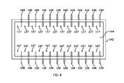
図4および5は、複数の電極を含む溶融容器14の代替的な実施形態の上面断面図および端面断面図をそれぞれ示しており、第1の電極148のセットは溶融容器14の側壁142を通って延び、第2の電極147のセットは溶融容器14の床144を通って延びる。図4および5に示される実施形態では、各電極は、溶融容器14の内部チャンバ内へと所定の距離だけ延びる細長い本体を備えている。加えて、第2の電極のセットは、少なくとも1つの側壁142から所定の距離にある床144上の位置から延びる。
4 and 5 show top and end cross-sectional views, respectively, of an alternative embodiment of
図5から分かるように、第1のセットの電極148の各々は、床144に対して平行な平面(P)に対して角度(α)で延びている。角度(α)は、例えば、例えば約10度~約60度、さらには例えば約20度~約45度など、約0度~約75度の範囲でありうる。
As can be seen in FIG. 5, each of the
電極147および/または148の断面の幾何学形状は限定されていないが、ある特定の例示的な実施形態では、電極147および/または148は、実質的に円形または楕円形の断面を有する実質的に円筒形の形状を有することができる。正方形、長方形、および三角形などの他の断面もまた可能である。電極147および/または148の直径は、限定されていないが、例えば、約3インチ(約7.62cm)を含む約2~4インチ(約5.08~10.16cm)など、約1~5インチ(約2.54~12.7cm)の範囲でありうる。図2および3を参照して説明した実施形態と同様に、電極147および/または148は、高温ガラス溶融物に対して適切な耐食性も示す、屈折特性を有する任意の導電材料から構成することができる。例示的な電極材料としては、限定はしないが、スズ、モリブデン、白金、並びにそれらの合金および酸化物からなる群より選択される少なくとも1つの材料が挙げられる。
Although the cross-sectional geometry of
ある特定の例示的な実施形態では、第2の電極147のセットは、ガラス溶融物の深さの約60%~約75%を含む、例えば少なくとも約65%、さらには例えば少なくとも約70%など、少なくとも約60%だけ、床上の位置から上方へと延びることができる。このような電極はまた、例えば、溶融容器142の幅の例えば約5%~約20%など、少なくとも約5%、例えば少なくとも約10%、さらには例えば少なくとも約15%の距離だけ、最も近い側壁から離れて延在しうる。
In certain exemplary embodiments, the set of
図5に示される実施形態では、ガラス溶融物内へと最も遠くまで延びる電極147および148の部分は、ガラス溶融物中でほぼ同じおおよその高さにあり、かつ、最も近い側壁からほぼ同じおおよその距離にあるが、本明細書に開示される実施形態はそのように限定されず、ガラス溶融物内へと最も遠く延びる電極147の部分が、ガラス溶融物内へと最も遠くまで延びる電極148の部分と比較して、ガラス溶融物内でより高いまたはより低い高さでありうる、および/または、最も近い側壁からより近くまたはより遠くにありうるものも含むことが理解されるべきである。ある特定の実施形態では、個々の電極147は、異なる高さ、直径、および/または最も近い側壁からの距離のものでありうることが理解されるべきである。加えて、ある特定の実施形態では、個々の電極148は、ガラス溶融物内へと異なる距離で延び、床144に平行な平面に対して異なる角度で延び、および/または異なる直径を有することができる。
In the embodiment shown in FIG. 5, the portions of
図4および5の実施形態は、各対向する側壁142が、そこを通って延びる12の電極148を含み、床144が、電極148に対して交互の配置で、そこを通って延びる24の電極147を含む、2つの対向する側壁142を含む溶融容器14を示しているが、本明細書に開示される実施形態は、2つの対向する側壁および床の各々が、各対向する側壁および/または床を通って延びる、例えば2~50の電極、さらには例えば5~20の電極など、各対向する側壁および/または床を通って延びる1~100の電極を含む、各対向する側壁および/または床を通って延びる少なくとも1つの電極、少なくとも2つの電極、少なくとも3つの電極など、そこを通って延びる任意の数の電極を有するものを含む、別の構成を含みうることが理解されるべきである。例えば、各対向する側壁および/または床は、そこを通って延びるN個の電極を有することができ、ここで、電極間の最短距離は、溶融容器の長さの約5%を含む、例えば約2%~約15%、さらには例えば約3%~約10%、さらに例えば約4%~約8%など、例えば約1%~約20%の範囲である。
4 and 5, each opposing
本明細書に開示される実施形態は、比較的高いまたは低い電気抵抗率を有するものを含む、さまざまなガラス組成物とともに使用することができる。このような組成物は、例えば、58~65質量%のSiO2、14~20質量%のAl2O3、8~12質量%のB2O3、1~3質量%のMgO、5~10質量%のCaO、および0.5~2質量%のSrOを含有する無アルカリガラス組成物などのガラス組成物を含みうる。このような組成物はまた、58~65質量%のSiO2、16~22質量%のAl2O3、1~5質量%のB2O3、1~4質量%のMgO、2~6質量%のCaO、1~4質量%のSrO、および5~10質量%のBaOを含有する無アルカリガラス組成物などのガラス組成物も含みうる。このような組成物は、さらには、57~61質量%のSiO2、17~21質量%のAl2O3、5~8質量%のB2O3、1~5質量%のMgO、3~9質量%のCaO、0~6質量%のSrO、および0~7質量%のBaOを含有する無アルカリガラス組成物などのガラス組成物も含みうる。このような組成物は、追加的に、55~72質量%のSiO2、12~24質量%のAl2O3、10~18質量%のNa2O、0~10質量%のB2O3、0~5質量%のK2O、0~5質量%のMgO、および0~5質量%のCaOを含み、ある特定の実施形態では、1~5質量%のK2Oおよび1~5質量%のMgOも含みうる、例えばアルカリ含有ガラス組成物などのガラス組成物を含みうる。 Embodiments disclosed herein can be used with a variety of glass compositions, including those with relatively high or low electrical resistivities. Such compositions include, for example, 58-65% by weight SiO 2 , 14-20% by weight Al 2 O 3 , 8-12% by weight B 2 O 3 , 1-3% by weight MgO, Glass compositions such as alkali-free glass compositions containing 10% by weight CaO and 0.5-2% by weight SrO may be included. Such compositions also contain 58-65% by weight SiO 2 , 16-22% by weight Al 2 O 3 , 1-5% by weight B 2 O 3 , 1-4% by weight MgO, 2-6% Glass compositions, such as alkali-free glass compositions containing weight percent CaO, 1-4 weight percent SrO, and 5-10 weight percent BaO may also be included. Such compositions further comprise 57-61% by weight SiO 2 , 17-21% by weight Al 2 O 3 , 5-8% by weight B 2 O 3 , 1-5% by weight MgO, 3 Glass compositions such as alkali-free glass compositions containing ∼9 wt% CaO, 0-6 wt% SrO, and 0-7 wt% BaO may also be included. Such compositions additionally contain 55-72% by weight SiO 2 , 12-24% by weight Al 2 O 3 , 10-18% by weight Na 2 O, 0-10% by weight B 2 O 3 , comprising 0-5 wt.% K 2 O, 0-5 wt.% MgO, and 0-5 wt.% CaO, and in certain embodiments, 1-5 wt.% K 2 O and 1-5 wt. It may include glass compositions, such as alkali-containing glass compositions, which may also include 5% by weight MgO.
本明細書に開示される実施形態は、テレビ、タブレット、およびスマートフォンなどの高解像度ディスプレイを有する電子デバイスを含む、電子デバイスに使用されるガラスシートなどのガラス物品の製造に使用することができる。 Embodiments disclosed herein can be used in the manufacture of glass articles such as glass sheets used in electronic devices, including electronic devices with high resolution displays such as televisions, tablets, and smart phones.
本明細書に開示される実施形態に従って電極および溶融容器の幾何学形状を構成することによって、ガラス溶融物と接触する耐火材料の破壊条件を超えることなく、少なくとも約1600℃の平均温度でガラス溶融物を加熱することができる。この点に関し、出願人が行ったモデル化実験は、ガラスが上記組成のいずれかを含み、耐火物がジルコニアを含む場合などに、少なくとも約1600℃のガラスおよび耐火物温度において、電極の構成および溶融容器の幾何学形状が、ガラス溶融物内で発生したパワーに対する、ガラス溶融物界面において耐火材料内で発生したパワーの量に実質的に影響を及ぼすことを示唆している。一方、ある特定の高温溶融操作では、十分な電極電力によって、ガラス溶融物が少なくとも約1600℃の平均温度に達することができなければならないが、このような電力は、とりわけ5,000時間を超える期間では、ガラス溶融物界面における耐火材料の破壊条件を超えると以前に予想されていた。本明細書に開示される電極構成および溶融容器の幾何学形状を含む本明細書に開示される実施形態は、この問題に対する解決策を提供し、代替的な構成および幾何学形状に対して耐火物内で発生するパワーの量を少なくとも30%削減することができる。本明細書に開示される実施形態はまた、より柔軟な溶融システム操作を可能にすることができ、溶融システム構成を変更する必要なしに、異なる電気抵抗率および異なる温度条件を有する異なるガラス組成物を利用することができる。 By configuring the electrode and melting vessel geometries in accordance with the embodiments disclosed herein, the glass melts at an average temperature of at least about 1600° C. without exceeding the failure conditions of refractory materials in contact with the glass melt. You can heat things. In this regard, modeling experiments conducted by Applicants show that electrode configurations and It has been suggested that the geometry of the melting vessel substantially affects the amount of power generated within the refractory material at the glass melt interface relative to the power generated within the glass melt. On the other hand, for certain high temperature melting operations, sufficient electrode power must allow the glass melt to reach an average temperature of at least about 1600° C., but such power typically exceeds 5,000 hours. It was previously expected to exceed failure conditions for refractory materials at the glass-melt interface for a period of time. The embodiments disclosed herein, including the electrode configurations and melt vessel geometries disclosed herein, provide a solution to this problem and are refractory to alternative configurations and geometries. The amount of power generated within the object can be reduced by at least 30%. Embodiments disclosed herein can also allow for more flexible melting system operation, allowing different glass compositions with different electrical resistivities and different temperature conditions to be processed without the need to change the melting system configuration. can be used.
本開示の精神および範囲から逸脱することなく、本開示の実施形態に対してさまざまな修正および変形がなされうることは、当業者にとって明白であろう。よって、本開示は、添付の特許請求の範囲およびそれらの等価物の範囲内に入ることを条件として、そのような修正および変形にも及ぶことが意図されている。 It will be apparent to those skilled in the art that various modifications and variations can be made to the embodiments of this disclosure without departing from the spirit and scope of this disclosure. Thus, it is intended that the present disclosure cover such modifications and variations provided they come within the scope of the appended claims and their equivalents.
以下、本発明の好ましい実施形態を項分け記載する。 Hereinafter, preferred embodiments of the present invention will be described item by item.
実施形態1
耐火材料を含む、少なくとも1つの側壁および床と、
前記耐火材料を通って延びる少なくとも1つの電極と
を含む、ガラス溶融送達システム容器であって、
前記少なくとも1つの電極が、ガラス溶融物と接触する前記耐火材料の破壊条件を超えることなく、前記耐火材料と接触するガラス溶融物を少なくとも約1600℃の平均温度で加熱するように構成される、
ガラス溶融送達システム容器。
Embodiment 1
at least one side wall and floor comprising a refractory material;
at least one electrode extending through the refractory material; and
the at least one electrode is configured to heat a glass melt in contact with the refractory material to an average temperature of at least about 1600° C. without exceeding a failure condition of the refractory material in contact with the glass melt;
Glass melt delivery system vessel.
実施形態2
前記耐火材料がジルコニアを含む、実施形態1に記載のガラス溶融送達システム容器。
Embodiment 2
3. The glass melt delivery system container of embodiment 1, wherein the refractory material comprises zirconia.
実施形態3
前記容器が、前記耐火材料と接触する前記ガラス溶融物を、少なくとも約5,000時間の間、少なくとも約1600℃の平均温度へと加熱するように構成される、実施形態1に記載のガラス溶融送達システム容器。
Embodiment 3
2. The glass melt of embodiment 1, wherein the vessel is configured to heat the glass melt in contact with the refractory material to an average temperature of at least about 1600° C. for at least about 5,000 hours. Delivery system container.
実施形態4
前記溶融容器が長さおよび幅を有し、前記長さの前記幅に対する比が、約2.4:1~約3.6:1の範囲である、実施形態1に記載のガラス溶融送達システム容器。
Embodiment 4
2. The glass melt delivery system of embodiment 1, wherein said melt vessel has a length and width, and wherein a ratio of said length to said width ranges from about 2.4:1 to about 3.6:1. container.
実施形態5
前記溶融容器が、該溶融容器の前記幅の少なくとも約50%の深さを有するガラス溶融物を受け入れるように構成されている、実施形態4に記載のガラス溶融送達システム容器。
Embodiment 5
5. The glass melt delivery system container of embodiment 4, wherein the melt container is configured to receive a glass melt having a depth of at least about 50% of the width of the melt container.
実施形態6
前記溶融容器が2つの対向する側壁を含み、各対向する側壁がそこを通って延びる少なくとも2つの電極を備えており、電極間の最短距離と前記側壁の長手方向における該電極の幅との比が、約0.8:1~約2.4:1の範囲である、実施形態4に記載のガラス溶融送達システム容器。
Embodiment 6
The melt vessel includes two opposing sidewalls, each opposing sidewall having at least two electrodes extending therethrough, the ratio of the shortest distance between the electrodes to the width of the electrodes in the longitudinal direction of the sidewalls. is in the range of about 0.8:1 to about 2.4:1.
実施形態7
前記容器内の前記ガラス溶融物の体積(V)および前記床と前記少なくとも1つの電極の底部との間の垂直距離(Y)が、関係(V)/(Y)3<60,000を満たす、実施形態1に記載のガラス溶融送達システム容器。
Embodiment 7
the volume (V) of the glass melt in the vessel and the vertical distance (Y) between the floor and the bottom of the at least one electrode satisfies the relationship (V)/(Y) 3 <60,000 A glass melt delivery system container according to embodiment 1.
実施形態8
前記少なくとも1つの電極が、前記溶融容器の内部チャンバ内へと所定の距離だけ延びる細長い本体を備えている、実施形態1に記載のガラス溶融送達システム容器。
Embodiment 8
2. A glass melt delivery system vessel according to embodiment 1, wherein the at least one electrode comprises an elongated body extending a predetermined distance into the interior chamber of the melting vessel.
実施形態9
前記少なくとも1つの電極が、前記床に平行な平面に対して約0度~約75度の範囲の角度で延びる、実施形態8に記載のガラス溶融送達システム容器。
Embodiment 9
9. The glass melt delivery system vessel of embodiment 8, wherein the at least one electrode extends at an angle ranging from about 0 degrees to about 75 degrees with respect to a plane parallel to the floor.
実施形態10
前記溶融容器が、前記少なくとも1つの側壁から所定の距離にある前記床上の位置から前記溶融容器の内部チャンバ内へと所定の距離だけ延びる細長い本体を備えている少なくとも1つの電極を含む、実施形態8に記載のガラス溶融送達システム容器。
An embodiment wherein said melting vessel comprises at least one electrode comprising an elongated body extending a predetermined distance into an interior chamber of said melting vessel from a position on said floor at a predetermined distance from said at least one side wall. 9. The glass melt delivery system container according to 8.
実施形態11
前記少なくとも1つの電極が、スズ、モリブデン、白金、並びにそれらの合金および酸化物からなる群より選択される少なくとも1つの材料を含む、実施形態1に記載のガラス溶融送達システム容器。
Embodiment 11
2. The glass melt delivery system vessel of embodiment 1, wherein the at least one electrode comprises at least one material selected from the group consisting of tin, molybdenum, platinum, and alloys and oxides thereof.
実施形態12
ガラス物品の製造方法であって、該方法が、ガラス溶融送達システム容器内でガラス組成物を処理する工程を含み、前記ガラス溶融送達システム容器が、
耐火材料を含む、少なくとも1つの側壁および床と、
前記耐火材料を通って延びる少なくとも1つの電極と
を含み、
前記少なくとも1つの電極が、ガラス溶融物と接触する前記耐火材料の破壊条件を超えることなく、前記耐火材料と接触するガラス溶融物を少なくとも約1600℃の平均温度で加熱する、
方法。
1. A method of making a glass article, the method comprising processing a glass composition in a glass melt delivery system container, the glass melt delivery system container comprising:
at least one side wall and floor comprising a refractory material;
at least one electrode extending through the refractory material;
the at least one electrode heats the glass melt in contact with the refractory material to an average temperature of at least about 1600° C. without exceeding a failure condition of the refractory material in contact with the glass melt;
Method.
実施形態13
前記耐火材料がジルコニアを含む、実施形態12に記載の方法。
Embodiment 13
13. The method of
実施形態14
前記耐火材料と接触する前記ガラス溶融物が、少なくとも約5,000時間の間、少なくとも約1600℃の平均温度へと加熱される、実施形態12に記載の方法。
13. The method of
実施形態15
前記溶融容器が長さおよび幅を有し、前記長さの前記幅に対する比が、約2.4:1~約3.6:1の範囲である、実施形態12に記載の方法。
Embodiment 15
13. The method of
実施形態16
前記ガラス溶融物が、前記溶融容器の前記幅の少なくとも約50%の深さを有する、実施形態15に記載の方法。
16. The method of embodiment 15, wherein the glass melt has a depth of at least about 50% of the width of the melting vessel.
実施形態17
前記溶融容器が2つの対向する側壁を含み、各対向する側壁がそこを通って延びる少なくとも2つの電極を備えており、電極間の最短距離と前記側壁の長手方向における該電極の幅との比が、約0.8:1~約2.4:1の範囲である、実施形態15に記載の方法。
Embodiment 17
The melt vessel includes two opposing sidewalls, each opposing sidewall having at least two electrodes extending therethrough, the ratio of the shortest distance between the electrodes to the width of the electrodes in the longitudinal direction of the sidewalls. is in the range of about 0.8:1 to about 2.4:1.
実施形態18
前記容器内の前記ガラス溶融物の体積(V)および前記床と前記少なくとも1つの電極の底部との間の垂直距離(Y)が、関係(V)/(Y)3<60,000を満たす、実施形態12に記載の方法。
the volume (V) of the glass melt in the vessel and the vertical distance (Y) between the floor and the bottom of the at least one electrode satisfies the relationship (V)/(Y) 3 <60,000 13. The method of
実施形態19
前記少なくとも1つの電極が、前記溶融容器の内部チャンバ内へと所定の距離だけ延びる細長い本体を備えている、実施形態12に記載の方法。
13. The method of
実施形態20
前記少なくとも1つの電極が、前記床に平行な平面に対して約0度~約75度の範囲の角度で延びる、実施形態19に記載の方法。
20. The method of
実施形態21
前記溶融容器が、前記少なくとも1つの側壁から所定の距離にある前記床上の位置から前記溶融容器の内部チャンバ内へと所定の距離だけ延びる細長い本体を備えている少なくとも1つの電極を含む、実施形態19に記載の方法。
Embodiment 21
An embodiment wherein said melting vessel comprises at least one electrode comprising an elongated body extending a predetermined distance into an interior chamber of said melting vessel from a position on said floor at a predetermined distance from said at least one side wall. 19. The method according to 19.
実施形態22
前記少なくとも1つの電極が、スズ、モリブデン、白金、並びにそれらの合金および酸化物からなる群より選択される少なくとも1つの材料を含む、実施形態12に記載の方法。
13. The method of
実施形態23
実施形態12に記載の方法によって製造されたガラス物品。
Embodiment 23
A glass article made by the method of
実施形態24
前記ガラス物品がガラスシートである、実施形態23に記載のガラス物品。
Embodiment 24
24. The glass article of embodiment 23, wherein the glass article is a glass sheet.
実施形態25
実施形態24に記載のガラスシートを含む、電子デバイス。
Embodiment 25
An electronic device comprising the glass sheet of embodiment 24.
10 ガラス製造装置
12 ガラス溶融炉
14 溶融容器
16 上流ガラス製造装置
18 貯蔵ビン
20 原料送達デバイス
22 モーター
24 原料
28 溶融ガラス
30 下流ガラス製造装置
32 第1の接続導管
34 清澄容器
36 混合容器
38 第2の接続導管
40 送達容器
42 成形本体
44 出口導管
46 第3の接続導管
48 成形装置
50 入口導管
52 トラフ
54 収束成形面
56 底縁部
58 ガラスリボン
60 延伸方向
62 ガラスシート
64 ロボット
65 把持具
100 ガラス分離装置
142 側壁
144 床
146,147,148 電極
282 ガラス溶融線
10
Claims (12)
前記耐火材料を通って延びる少なくとも1つの電極と
を含む、ガラス溶融送達システム容器であって、
前記少なくとも1つの電極が、ガラス溶融物と接触する前記耐火材料の破壊条件を超えることなく、前記耐火材料と接触するガラス溶融物を少なくとも1600℃の平均温度で加熱するように構成され、
前記溶融容器が長さおよび幅を有し、前記長さの前記幅に対する比が、2.4:1~3.6:1の範囲であり、
前記溶融容器が、該溶融容器の前記幅の少なくとも50%の深さを有するガラス溶融物を受け入れるように構成されている、ガラス溶融送達システム容器。 sidewalls and floors comprising a refractory material comprising zirconia;
at least one electrode extending through the refractory material; and
wherein the at least one electrode is configured to heat a glass melt in contact with the refractory material to an average temperature of at least 1600° C. without exceeding a failure condition of the refractory material in contact with the glass melt;
Said melt vessel has a length and a width, and the ratio of said length to said width is 2 . 4:1 to 3 . in the range of 6:1;
A glass melt delivery system vessel, wherein said melt vessel is configured to receive a glass melt having a depth of at least 50 % of said width of said melt vessel.
ジルコニアを含む耐火材料を含む、側壁および床と、
前記耐火材料を通って延びる少なくとも1つの電極と
を含み、
前記少なくとも1つの電極が、ガラス溶融物と接触する前記耐火材料の破壊条件を超えることなく、前記耐火材料と接触するガラス溶融物を少なくとも1600℃の平均温度で加熱し、
前記溶融容器が2つの対向する側壁を含み、各対向する側壁が、該側壁を通って延びる少なくとも2つの電極を備えており、電極間の最短距離と前記側壁の長手方向における該電極の幅との比が、0.8:1~2.4:1の範囲であり、
前記床と前記少なくとも1つの電極の底部との間の垂直距離が、垂直方向の前記電極の長さの少なくとも5%である、
方法。 1. A method of making a glass article, the method comprising processing a glass composition in a glass melt delivery system container, the glass melt delivery system container comprising:
sidewalls and floors comprising a refractory material comprising zirconia;
at least one electrode extending through the refractory material;
wherein the at least one electrode heats the glass melt in contact with the refractory material to an average temperature of at least 1600° C. without exceeding a failure condition of the refractory material in contact with the glass melt;
The melt vessel includes two opposing sidewalls, each opposing sidewall having at least two electrodes extending through the sidewalls, the minimum distance between the electrodes and the width of the electrodes in the longitudinal direction of the sidewalls. If the ratio of 0 . 8: 1-2 . in the range of 4:1;
the vertical distance between the floor and the bottom of the at least one electrode is at least 5 % of the length of the electrode in the vertical direction;
Method.
Applications Claiming Priority (3)
| Application Number | Priority Date | Filing Date | Title |
|---|---|---|---|
| US201662419133P | 2016-11-08 | 2016-11-08 | |
| US62/419,133 | 2016-11-08 | ||
| PCT/US2017/060474 WO2018089387A1 (en) | 2016-11-08 | 2017-11-07 | High temperature glass melting vessel |
Publications (3)
| Publication Number | Publication Date |
|---|---|
| JP2019534237A JP2019534237A (en) | 2019-11-28 |
| JP2019534237A5 JP2019534237A5 (en) | 2021-01-07 |
| JP7105794B2 true JP7105794B2 (en) | 2022-07-25 |
Family
ID=62109380
Family Applications (1)
| Application Number | Title | Priority Date | Filing Date |
|---|---|---|---|
| JP2019545888A Active JP7105794B2 (en) | 2016-11-08 | 2017-11-07 | high temperature glass melting vessel |
Country Status (6)
| Country | Link |
|---|---|
| US (1) | US11028001B2 (en) |
| JP (1) | JP7105794B2 (en) |
| KR (1) | KR102412297B1 (en) |
| CN (1) | CN109923077B (en) |
| TW (1) | TWI756290B (en) |
| WO (1) | WO2018089387A1 (en) |
Families Citing this family (2)
| Publication number | Priority date | Publication date | Assignee | Title |
|---|---|---|---|---|
| DE102019217977A1 (en) * | 2019-11-21 | 2021-05-27 | Schott Ag | Glass, a method for making a glass and a glass melting plant |
| CN115385553A (en) * | 2022-07-28 | 2022-11-25 | 陕西彩虹工业智能科技有限公司 | Microcrystalline glass's smelting device |
Citations (5)
| Publication number | Priority date | Publication date | Assignee | Title |
|---|---|---|---|---|
| JP2001019436A (en) | 1999-05-28 | 2001-01-23 | Carl Zeiss:Fa | Tank and method for melting glass |
| JP2006516046A (en) | 2002-12-03 | 2006-06-15 | ショット アクチエンゲゼルシャフト | Melt heating method and apparatus |
| JP2009523697A (en) | 2006-01-24 | 2009-06-25 | ショット アクチエンゲゼルシャフト | Method and apparatus for anticorrosion of electrodes when affecting the temperature of the melt |
| JP2009523698A (en) | 2006-01-24 | 2009-06-25 | ショット アクチエンゲゼルシャフト | Melt temperature operation method |
| JP2012250906A (en) | 2011-05-31 | 2012-12-20 | Corning Inc | Glass melt handling equipment and method |
Family Cites Families (18)
| Publication number | Priority date | Publication date | Assignee | Title |
|---|---|---|---|---|
| US2267537A (en) * | 1939-07-17 | 1941-12-23 | Saint Gobain | Electric furnace |
| US2523030A (en) * | 1948-10-30 | 1950-09-19 | Glass Fibers Inc | Electric glass furnace |
| US3530221A (en) | 1968-05-01 | 1970-09-22 | Penberthy Harvey Larry | Ac/dc electrode and power supply system for a glass furnace |
| GB1281424A (en) | 1970-06-08 | 1972-07-12 | Harvey Larry Penberthy | Ac/dc electrode and power supply system for a glass furnace |
| US3941577A (en) * | 1974-11-29 | 1976-03-02 | Ppg Industries, Inc. | Method and apparatus for making molten glass |
| US4143232A (en) * | 1976-11-01 | 1979-03-06 | Corning Glass Works | Furnace having different electrode immersions to control convection currents, the shape, elevation and stability of the fusion zone |
| US5283803A (en) | 1992-06-01 | 1994-02-01 | Glass Incorporated International | Electrode assembly for glass melting furnace |
| US7823417B2 (en) | 2005-11-04 | 2010-11-02 | Ocv Intellectual Capital, Llc | Method of manufacturing high performance glass fibers in a refractory lined melter and fiber formed thereby |
| FR2897861B1 (en) | 2006-02-24 | 2008-06-13 | Saint Gobain Ct Recherches | REFRACTORY WITH HIGH RESISTANCE ZIRCONIA CONTENT |
| US20080057275A1 (en) | 2006-08-31 | 2008-03-06 | Paul Richard Grzesik | Method and apparatus for minimizing oxidation pitting of refractory metal vessels |
| FR2922283B1 (en) | 2007-10-10 | 2011-10-21 | Valeo Embrayages | CLUTCH MECHANISM, ESPECIALLY FOR A MOTOR VEHICLE |
| US8087262B2 (en) * | 2008-11-18 | 2012-01-03 | Corning Incorporated | Platinum condensation abatement by electrostatic precipitation |
| FR2978144B1 (en) * | 2011-07-22 | 2013-08-30 | Saint Gobain Ct Recherches | REFRACTORY BLOCK AND GLASS FUSION OVEN |
| WO2014036979A1 (en) * | 2012-09-05 | 2014-03-13 | Vysoká škola chemicko-technologická v Praze | Method for continuous glass melting under controlled convection of glass melt and glass melting furnace for making the same |
| US8973406B2 (en) * | 2012-10-26 | 2015-03-10 | Corning Incorporated | Melters for glass forming apparatuses |
| US9725349B2 (en) * | 2012-11-28 | 2017-08-08 | Corning Incorporated | Glass manufacturing apparatus and methods |
| CN204474521U (en) * | 2015-04-01 | 2015-07-15 | 秦皇岛弘华特种玻璃有限公司 | The All Electric Melting Furnace of fusing borosilicate glass |
| CN105776819B (en) | 2016-04-27 | 2018-07-31 | 巨石集团有限公司 | A kind of cell furnace with high melting rate |
-
2017
- 2017-11-07 KR KR1020197016113A patent/KR102412297B1/en active IP Right Grant
- 2017-11-07 WO PCT/US2017/060474 patent/WO2018089387A1/en active Application Filing
- 2017-11-07 CN CN201780069113.9A patent/CN109923077B/en active Active
- 2017-11-07 US US16/348,142 patent/US11028001B2/en active Active
- 2017-11-07 JP JP2019545888A patent/JP7105794B2/en active Active
- 2017-11-08 TW TW106138590A patent/TWI756290B/en active
Patent Citations (5)
| Publication number | Priority date | Publication date | Assignee | Title |
|---|---|---|---|---|
| JP2001019436A (en) | 1999-05-28 | 2001-01-23 | Carl Zeiss:Fa | Tank and method for melting glass |
| JP2006516046A (en) | 2002-12-03 | 2006-06-15 | ショット アクチエンゲゼルシャフト | Melt heating method and apparatus |
| JP2009523697A (en) | 2006-01-24 | 2009-06-25 | ショット アクチエンゲゼルシャフト | Method and apparatus for anticorrosion of electrodes when affecting the temperature of the melt |
| JP2009523698A (en) | 2006-01-24 | 2009-06-25 | ショット アクチエンゲゼルシャフト | Melt temperature operation method |
| JP2012250906A (en) | 2011-05-31 | 2012-12-20 | Corning Inc | Glass melt handling equipment and method |
Also Published As
| Publication number | Publication date |
|---|---|
| KR20190078620A (en) | 2019-07-04 |
| JP2019534237A (en) | 2019-11-28 |
| US20190276346A1 (en) | 2019-09-12 |
| KR102412297B1 (en) | 2022-06-24 |
| CN109923077A (en) | 2019-06-21 |
| TWI756290B (en) | 2022-03-01 |
| TW201825414A (en) | 2018-07-16 |
| WO2018089387A1 (en) | 2018-05-17 |
| CN109923077B (en) | 2022-05-13 |
| US11028001B2 (en) | 2021-06-08 |
Similar Documents
| Publication | Publication Date | Title |
|---|---|---|
| US11512015B2 (en) | Method and apparatus for glass ribbon thermal control | |
| JP7105794B2 (en) | high temperature glass melting vessel | |
| WO2017223034A1 (en) | Apparatus and method for glass delivery orientation | |
| US11130696B2 (en) | Methods for reconditioning glass manufacturing systems | |
| WO2019018670A1 (en) | Method and apparatus for adjustable glass ribbon heat transfer | |
| CN216918999U (en) | Glass manufacturing apparatus with leakage mitigation features | |
| WO2018081664A1 (en) | Liquid metal viscosity control of molten glass | |
| WO2023163897A1 (en) | Glass melting furnaces and vessels with improved thermal performance | |
| JP2019516661A (en) | System and method for upset management of roles | |
| KR20210119534A (en) | Conduit heating apparatus and method with improved corrosion resistance | |
| CN116670080A (en) | Glass manufacturing apparatus | |
| WO2023163898A1 (en) | Glass melting furnaces and vessels with improved electrical resistivity | |
| WO2024091384A1 (en) | Apparatus and method for manufacturing a glass article | |
| CN115175879A (en) | Laser scribing of glass | |
| CN112055698A (en) | Discharge conduit for glass melting system |
Legal Events
| Date | Code | Title | Description |
|---|---|---|---|
| A521 | Request for written amendment filed |
Free format text: JAPANESE INTERMEDIATE CODE: A523 Effective date: 20201109 |
|
| A621 | Written request for application examination |
Free format text: JAPANESE INTERMEDIATE CODE: A621 Effective date: 20201109 |
|
| A977 | Report on retrieval |
Free format text: JAPANESE INTERMEDIATE CODE: A971007 Effective date: 20210705 |
|
| A131 | Notification of reasons for refusal |
Free format text: JAPANESE INTERMEDIATE CODE: A131 Effective date: 20210714 |
|
| A521 | Request for written amendment filed |
Free format text: JAPANESE INTERMEDIATE CODE: A523 Effective date: 20210922 |
|
| A02 | Decision of refusal |
Free format text: JAPANESE INTERMEDIATE CODE: A02 Effective date: 20211020 |
|
| A521 | Request for written amendment filed |
Free format text: JAPANESE INTERMEDIATE CODE: A523 Effective date: 20220127 |
|
| C60 | Trial request (containing other claim documents, opposition documents) |
Free format text: JAPANESE INTERMEDIATE CODE: C60 Effective date: 20220127 |
|
| A911 | Transfer to examiner for re-examination before appeal (zenchi) |
Free format text: JAPANESE INTERMEDIATE CODE: A911 Effective date: 20220204 |
|
| C21 | Notice of transfer of a case for reconsideration by examiners before appeal proceedings |
Free format text: JAPANESE INTERMEDIATE CODE: C21 Effective date: 20220209 |
|
| A131 | Notification of reasons for refusal |
Free format text: JAPANESE INTERMEDIATE CODE: A131 Effective date: 20220330 |
|
| A521 | Request for written amendment filed |
Free format text: JAPANESE INTERMEDIATE CODE: A523 Effective date: 20220531 |
|
| TRDD | Decision of grant or rejection written | ||
| A01 | Written decision to grant a patent or to grant a registration (utility model) |
Free format text: JAPANESE INTERMEDIATE CODE: A01 Effective date: 20220615 |
|
| A61 | First payment of annual fees (during grant procedure) |
Free format text: JAPANESE INTERMEDIATE CODE: A61 Effective date: 20220712 |
|
| R150 | Certificate of patent or registration of utility model |
Ref document number: 7105794 Country of ref document: JP Free format text: JAPANESE INTERMEDIATE CODE: R150 |