JP7105690B2 - A Process for the Production of High Biogenic Concentration Fischer-Tropsch Liquids Derived from Municipal Solid Waste (MSW) Feedstocks - Google Patents
A Process for the Production of High Biogenic Concentration Fischer-Tropsch Liquids Derived from Municipal Solid Waste (MSW) Feedstocks Download PDFInfo
- Publication number
- JP7105690B2 JP7105690B2 JP2018521818A JP2018521818A JP7105690B2 JP 7105690 B2 JP7105690 B2 JP 7105690B2 JP 2018521818 A JP2018521818 A JP 2018521818A JP 2018521818 A JP2018521818 A JP 2018521818A JP 7105690 B2 JP7105690 B2 JP 7105690B2
- Authority
- JP
- Japan
- Prior art keywords
- syngas
- carbon
- biogenic
- stream
- fischer
- Prior art date
- Legal status (The legal status is an assumption and is not a legal conclusion. Google has not performed a legal analysis and makes no representation as to the accuracy of the status listed.)
- Active
Links
Images


Classifications
-
- C—CHEMISTRY; METALLURGY
- C10—PETROLEUM, GAS OR COKE INDUSTRIES; TECHNICAL GASES CONTAINING CARBON MONOXIDE; FUELS; LUBRICANTS; PEAT
- C10L—FUELS NOT OTHERWISE PROVIDED FOR; NATURAL GAS; SYNTHETIC NATURAL GAS OBTAINED BY PROCESSES NOT COVERED BY SUBCLASSES C10G, C10K; LIQUEFIED PETROLEUM GAS; ADDING MATERIALS TO FUELS OR FIRES TO REDUCE SMOKE OR UNDESIRABLE DEPOSITS OR TO FACILITATE SOOT REMOVAL; FIRELIGHTERS
- C10L1/00—Liquid carbonaceous fuels
- C10L1/04—Liquid carbonaceous fuels essentially based on blends of hydrocarbons
-
- C—CHEMISTRY; METALLURGY
- C10—PETROLEUM, GAS OR COKE INDUSTRIES; TECHNICAL GASES CONTAINING CARBON MONOXIDE; FUELS; LUBRICANTS; PEAT
- C10G—CRACKING HYDROCARBON OILS; PRODUCTION OF LIQUID HYDROCARBON MIXTURES, e.g. BY DESTRUCTIVE HYDROGENATION, OLIGOMERISATION, POLYMERISATION; RECOVERY OF HYDROCARBON OILS FROM OIL-SHALE, OIL-SAND, OR GASES; REFINING MIXTURES MAINLY CONSISTING OF HYDROCARBONS; REFORMING OF NAPHTHA; MINERAL WAXES
- C10G2/00—Production of liquid hydrocarbon mixtures of undefined composition from oxides of carbon
-
- B—PERFORMING OPERATIONS; TRANSPORTING
- B01—PHYSICAL OR CHEMICAL PROCESSES OR APPARATUS IN GENERAL
- B01J—CHEMICAL OR PHYSICAL PROCESSES, e.g. CATALYSIS OR COLLOID CHEMISTRY; THEIR RELEVANT APPARATUS
- B01J19/00—Chemical, physical or physico-chemical processes in general; Their relevant apparatus
- B01J19/0006—Controlling or regulating processes
-
- B—PERFORMING OPERATIONS; TRANSPORTING
- B01—PHYSICAL OR CHEMICAL PROCESSES OR APPARATUS IN GENERAL
- B01J—CHEMICAL OR PHYSICAL PROCESSES, e.g. CATALYSIS OR COLLOID CHEMISTRY; THEIR RELEVANT APPARATUS
- B01J8/00—Chemical or physical processes in general, conducted in the presence of fluids and solid particles; Apparatus for such processes
-
- B—PERFORMING OPERATIONS; TRANSPORTING
- B09—DISPOSAL OF SOLID WASTE; RECLAMATION OF CONTAMINATED SOIL
- B09B—DISPOSAL OF SOLID WASTE
- B09B3/00—Destroying solid waste or transforming solid waste into something useful or harmless
- B09B3/10—Destroying solid waste or transforming solid waste into something useful or harmless involving an adsorption step
-
- C—CHEMISTRY; METALLURGY
- C07—ORGANIC CHEMISTRY
- C07C—ACYCLIC OR CARBOCYCLIC COMPOUNDS
- C07C29/00—Preparation of compounds having hydroxy or O-metal groups bound to a carbon atom not belonging to a six-membered aromatic ring
- C07C29/15—Preparation of compounds having hydroxy or O-metal groups bound to a carbon atom not belonging to a six-membered aromatic ring by reduction of oxides of carbon exclusively
- C07C29/151—Preparation of compounds having hydroxy or O-metal groups bound to a carbon atom not belonging to a six-membered aromatic ring by reduction of oxides of carbon exclusively with hydrogen or hydrogen-containing gases
- C07C29/1516—Multisteps
- C07C29/1518—Multisteps one step being the formation of initial mixture of carbon oxides and hydrogen for synthesis
-
- C—CHEMISTRY; METALLURGY
- C10—PETROLEUM, GAS OR COKE INDUSTRIES; TECHNICAL GASES CONTAINING CARBON MONOXIDE; FUELS; LUBRICANTS; PEAT
- C10G—CRACKING HYDROCARBON OILS; PRODUCTION OF LIQUID HYDROCARBON MIXTURES, e.g. BY DESTRUCTIVE HYDROGENATION, OLIGOMERISATION, POLYMERISATION; RECOVERY OF HYDROCARBON OILS FROM OIL-SHALE, OIL-SAND, OR GASES; REFINING MIXTURES MAINLY CONSISTING OF HYDROCARBONS; REFORMING OF NAPHTHA; MINERAL WAXES
- C10G2/00—Production of liquid hydrocarbon mixtures of undefined composition from oxides of carbon
- C10G2/30—Production of liquid hydrocarbon mixtures of undefined composition from oxides of carbon from carbon monoxide with hydrogen
- C10G2/32—Production of liquid hydrocarbon mixtures of undefined composition from oxides of carbon from carbon monoxide with hydrogen with the use of catalysts
- C10G2/34—Apparatus, reactors
-
- C—CHEMISTRY; METALLURGY
- C10—PETROLEUM, GAS OR COKE INDUSTRIES; TECHNICAL GASES CONTAINING CARBON MONOXIDE; FUELS; LUBRICANTS; PEAT
- C10G—CRACKING HYDROCARBON OILS; PRODUCTION OF LIQUID HYDROCARBON MIXTURES, e.g. BY DESTRUCTIVE HYDROGENATION, OLIGOMERISATION, POLYMERISATION; RECOVERY OF HYDROCARBON OILS FROM OIL-SHALE, OIL-SAND, OR GASES; REFINING MIXTURES MAINLY CONSISTING OF HYDROCARBONS; REFORMING OF NAPHTHA; MINERAL WAXES
- C10G47/00—Cracking of hydrocarbon oils, in the presence of hydrogen or hydrogen- generating compounds, to obtain lower boiling fractions
-
- C—CHEMISTRY; METALLURGY
- C10—PETROLEUM, GAS OR COKE INDUSTRIES; TECHNICAL GASES CONTAINING CARBON MONOXIDE; FUELS; LUBRICANTS; PEAT
- C10J—PRODUCTION OF PRODUCER GAS, WATER-GAS, SYNTHESIS GAS FROM SOLID CARBONACEOUS MATERIAL, OR MIXTURES CONTAINING THESE GASES; CARBURETTING AIR OR OTHER GASES
- C10J3/00—Production of combustible gases containing carbon monoxide from solid carbonaceous fuels
- C10J3/02—Fixed-bed gasification of lump fuel
- C10J3/20—Apparatus; Plants
- C10J3/22—Arrangements or dispositions of valves or flues
- C10J3/24—Arrangements or dispositions of valves or flues to permit flow of gases or vapours other than upwardly through the fuel bed
- C10J3/26—Arrangements or dispositions of valves or flues to permit flow of gases or vapours other than upwardly through the fuel bed downwardly
-
- C—CHEMISTRY; METALLURGY
- C10—PETROLEUM, GAS OR COKE INDUSTRIES; TECHNICAL GASES CONTAINING CARBON MONOXIDE; FUELS; LUBRICANTS; PEAT
- C10J—PRODUCTION OF PRODUCER GAS, WATER-GAS, SYNTHESIS GAS FROM SOLID CARBONACEOUS MATERIAL, OR MIXTURES CONTAINING THESE GASES; CARBURETTING AIR OR OTHER GASES
- C10J3/00—Production of combustible gases containing carbon monoxide from solid carbonaceous fuels
- C10J3/46—Gasification of granular or pulverulent flues in suspension
- C10J3/466—Entrained flow processes
-
- C—CHEMISTRY; METALLURGY
- C10—PETROLEUM, GAS OR COKE INDUSTRIES; TECHNICAL GASES CONTAINING CARBON MONOXIDE; FUELS; LUBRICANTS; PEAT
- C10J—PRODUCTION OF PRODUCER GAS, WATER-GAS, SYNTHESIS GAS FROM SOLID CARBONACEOUS MATERIAL, OR MIXTURES CONTAINING THESE GASES; CARBURETTING AIR OR OTHER GASES
- C10J3/00—Production of combustible gases containing carbon monoxide from solid carbonaceous fuels
- C10J3/46—Gasification of granular or pulverulent flues in suspension
- C10J3/48—Apparatus; Plants
- C10J3/485—Entrained flow gasifiers
-
- C—CHEMISTRY; METALLURGY
- C10—PETROLEUM, GAS OR COKE INDUSTRIES; TECHNICAL GASES CONTAINING CARBON MONOXIDE; FUELS; LUBRICANTS; PEAT
- C10J—PRODUCTION OF PRODUCER GAS, WATER-GAS, SYNTHESIS GAS FROM SOLID CARBONACEOUS MATERIAL, OR MIXTURES CONTAINING THESE GASES; CARBURETTING AIR OR OTHER GASES
- C10J3/00—Production of combustible gases containing carbon monoxide from solid carbonaceous fuels
- C10J3/72—Other features
- C10J3/721—Multistage gasification, e.g. plural parallel or serial gasification stages
-
- C—CHEMISTRY; METALLURGY
- C10—PETROLEUM, GAS OR COKE INDUSTRIES; TECHNICAL GASES CONTAINING CARBON MONOXIDE; FUELS; LUBRICANTS; PEAT
- C10J—PRODUCTION OF PRODUCER GAS, WATER-GAS, SYNTHESIS GAS FROM SOLID CARBONACEOUS MATERIAL, OR MIXTURES CONTAINING THESE GASES; CARBURETTING AIR OR OTHER GASES
- C10J3/00—Production of combustible gases containing carbon monoxide from solid carbonaceous fuels
- C10J3/72—Other features
- C10J3/82—Gas withdrawal means
-
- C—CHEMISTRY; METALLURGY
- C10—PETROLEUM, GAS OR COKE INDUSTRIES; TECHNICAL GASES CONTAINING CARBON MONOXIDE; FUELS; LUBRICANTS; PEAT
- C10K—PURIFYING OR MODIFYING THE CHEMICAL COMPOSITION OF COMBUSTIBLE GASES CONTAINING CARBON MONOXIDE
- C10K1/00—Purifying combustible gases containing carbon monoxide
- C10K1/002—Removal of contaminants
- C10K1/003—Removal of contaminants of acid contaminants, e.g. acid gas removal
- C10K1/004—Sulfur containing contaminants, e.g. hydrogen sulfide
-
- C—CHEMISTRY; METALLURGY
- C10—PETROLEUM, GAS OR COKE INDUSTRIES; TECHNICAL GASES CONTAINING CARBON MONOXIDE; FUELS; LUBRICANTS; PEAT
- C10K—PURIFYING OR MODIFYING THE CHEMICAL COMPOSITION OF COMBUSTIBLE GASES CONTAINING CARBON MONOXIDE
- C10K1/00—Purifying combustible gases containing carbon monoxide
- C10K1/002—Removal of contaminants
- C10K1/003—Removal of contaminants of acid contaminants, e.g. acid gas removal
- C10K1/005—Carbon dioxide
-
- C—CHEMISTRY; METALLURGY
- C10—PETROLEUM, GAS OR COKE INDUSTRIES; TECHNICAL GASES CONTAINING CARBON MONOXIDE; FUELS; LUBRICANTS; PEAT
- C10K—PURIFYING OR MODIFYING THE CHEMICAL COMPOSITION OF COMBUSTIBLE GASES CONTAINING CARBON MONOXIDE
- C10K1/00—Purifying combustible gases containing carbon monoxide
- C10K1/08—Purifying combustible gases containing carbon monoxide by washing with liquids; Reviving the used wash liquors
- C10K1/10—Purifying combustible gases containing carbon monoxide by washing with liquids; Reviving the used wash liquors with aqueous liquids
- C10K1/101—Purifying combustible gases containing carbon monoxide by washing with liquids; Reviving the used wash liquors with aqueous liquids with water only
-
- C—CHEMISTRY; METALLURGY
- C10—PETROLEUM, GAS OR COKE INDUSTRIES; TECHNICAL GASES CONTAINING CARBON MONOXIDE; FUELS; LUBRICANTS; PEAT
- C10K—PURIFYING OR MODIFYING THE CHEMICAL COMPOSITION OF COMBUSTIBLE GASES CONTAINING CARBON MONOXIDE
- C10K1/00—Purifying combustible gases containing carbon monoxide
- C10K1/08—Purifying combustible gases containing carbon monoxide by washing with liquids; Reviving the used wash liquors
- C10K1/16—Purifying combustible gases containing carbon monoxide by washing with liquids; Reviving the used wash liquors with non-aqueous liquids
-
- C—CHEMISTRY; METALLURGY
- C10—PETROLEUM, GAS OR COKE INDUSTRIES; TECHNICAL GASES CONTAINING CARBON MONOXIDE; FUELS; LUBRICANTS; PEAT
- C10K—PURIFYING OR MODIFYING THE CHEMICAL COMPOSITION OF COMBUSTIBLE GASES CONTAINING CARBON MONOXIDE
- C10K3/00—Modifying the chemical composition of combustible gases containing carbon monoxide to produce an improved fuel, e.g. one of different calorific value, which may be free from carbon monoxide
- C10K3/001—Modifying the chemical composition of combustible gases containing carbon monoxide to produce an improved fuel, e.g. one of different calorific value, which may be free from carbon monoxide by thermal treatment
-
- C—CHEMISTRY; METALLURGY
- C10—PETROLEUM, GAS OR COKE INDUSTRIES; TECHNICAL GASES CONTAINING CARBON MONOXIDE; FUELS; LUBRICANTS; PEAT
- C10K—PURIFYING OR MODIFYING THE CHEMICAL COMPOSITION OF COMBUSTIBLE GASES CONTAINING CARBON MONOXIDE
- C10K3/00—Modifying the chemical composition of combustible gases containing carbon monoxide to produce an improved fuel, e.g. one of different calorific value, which may be free from carbon monoxide
- C10K3/02—Modifying the chemical composition of combustible gases containing carbon monoxide to produce an improved fuel, e.g. one of different calorific value, which may be free from carbon monoxide by catalytic treatment
- C10K3/04—Modifying the chemical composition of combustible gases containing carbon monoxide to produce an improved fuel, e.g. one of different calorific value, which may be free from carbon monoxide by catalytic treatment reducing the carbon monoxide content, e.g. water-gas shift [WGS]
-
- C—CHEMISTRY; METALLURGY
- C10—PETROLEUM, GAS OR COKE INDUSTRIES; TECHNICAL GASES CONTAINING CARBON MONOXIDE; FUELS; LUBRICANTS; PEAT
- C10L—FUELS NOT OTHERWISE PROVIDED FOR; NATURAL GAS; SYNTHETIC NATURAL GAS OBTAINED BY PROCESSES NOT COVERED BY SUBCLASSES C10G, C10K; LIQUEFIED PETROLEUM GAS; ADDING MATERIALS TO FUELS OR FIRES TO REDUCE SMOKE OR UNDESIRABLE DEPOSITS OR TO FACILITATE SOOT REMOVAL; FIRELIGHTERS
- C10L1/00—Liquid carbonaceous fuels
- C10L1/04—Liquid carbonaceous fuels essentially based on blends of hydrocarbons
- C10L1/08—Liquid carbonaceous fuels essentially based on blends of hydrocarbons for compression ignition
-
- B—PERFORMING OPERATIONS; TRANSPORTING
- B01—PHYSICAL OR CHEMICAL PROCESSES OR APPARATUS IN GENERAL
- B01J—CHEMICAL OR PHYSICAL PROCESSES, e.g. CATALYSIS OR COLLOID CHEMISTRY; THEIR RELEVANT APPARATUS
- B01J2208/00—Processes carried out in the presence of solid particles; Reactors therefor
- B01J2208/00008—Controlling the process
- B01J2208/00017—Controlling the temperature
- B01J2208/00106—Controlling the temperature by indirect heat exchange
- B01J2208/00115—Controlling the temperature by indirect heat exchange with heat exchange elements inside the bed of solid particles
-
- C—CHEMISTRY; METALLURGY
- C10—PETROLEUM, GAS OR COKE INDUSTRIES; TECHNICAL GASES CONTAINING CARBON MONOXIDE; FUELS; LUBRICANTS; PEAT
- C10J—PRODUCTION OF PRODUCER GAS, WATER-GAS, SYNTHESIS GAS FROM SOLID CARBONACEOUS MATERIAL, OR MIXTURES CONTAINING THESE GASES; CARBURETTING AIR OR OTHER GASES
- C10J2300/00—Details of gasification processes
- C10J2300/09—Details of the feed, e.g. feeding of spent catalyst, inert gas or halogens
- C10J2300/0903—Feed preparation
- C10J2300/0906—Physical processes, e.g. shredding, comminuting, chopping, sorting
-
- C—CHEMISTRY; METALLURGY
- C10—PETROLEUM, GAS OR COKE INDUSTRIES; TECHNICAL GASES CONTAINING CARBON MONOXIDE; FUELS; LUBRICANTS; PEAT
- C10J—PRODUCTION OF PRODUCER GAS, WATER-GAS, SYNTHESIS GAS FROM SOLID CARBONACEOUS MATERIAL, OR MIXTURES CONTAINING THESE GASES; CARBURETTING AIR OR OTHER GASES
- C10J2300/00—Details of gasification processes
- C10J2300/09—Details of the feed, e.g. feeding of spent catalyst, inert gas or halogens
- C10J2300/0913—Carbonaceous raw material
- C10J2300/0946—Waste, e.g. MSW, tires, glass, tar sand, peat, paper, lignite, oil shale
-
- C—CHEMISTRY; METALLURGY
- C10—PETROLEUM, GAS OR COKE INDUSTRIES; TECHNICAL GASES CONTAINING CARBON MONOXIDE; FUELS; LUBRICANTS; PEAT
- C10J—PRODUCTION OF PRODUCER GAS, WATER-GAS, SYNTHESIS GAS FROM SOLID CARBONACEOUS MATERIAL, OR MIXTURES CONTAINING THESE GASES; CARBURETTING AIR OR OTHER GASES
- C10J2300/00—Details of gasification processes
- C10J2300/09—Details of the feed, e.g. feeding of spent catalyst, inert gas or halogens
- C10J2300/0953—Gasifying agents
- C10J2300/0959—Oxygen
-
- C—CHEMISTRY; METALLURGY
- C10—PETROLEUM, GAS OR COKE INDUSTRIES; TECHNICAL GASES CONTAINING CARBON MONOXIDE; FUELS; LUBRICANTS; PEAT
- C10J—PRODUCTION OF PRODUCER GAS, WATER-GAS, SYNTHESIS GAS FROM SOLID CARBONACEOUS MATERIAL, OR MIXTURES CONTAINING THESE GASES; CARBURETTING AIR OR OTHER GASES
- C10J2300/00—Details of gasification processes
- C10J2300/09—Details of the feed, e.g. feeding of spent catalyst, inert gas or halogens
- C10J2300/0953—Gasifying agents
- C10J2300/0973—Water
- C10J2300/0976—Water as steam
-
- C—CHEMISTRY; METALLURGY
- C10—PETROLEUM, GAS OR COKE INDUSTRIES; TECHNICAL GASES CONTAINING CARBON MONOXIDE; FUELS; LUBRICANTS; PEAT
- C10J—PRODUCTION OF PRODUCER GAS, WATER-GAS, SYNTHESIS GAS FROM SOLID CARBONACEOUS MATERIAL, OR MIXTURES CONTAINING THESE GASES; CARBURETTING AIR OR OTHER GASES
- C10J2300/00—Details of gasification processes
- C10J2300/16—Integration of gasification processes with another plant or parts within the plant
- C10J2300/1625—Integration of gasification processes with another plant or parts within the plant with solids treatment
- C10J2300/1628—Ash post-treatment
- C10J2300/1634—Ash vitrification
-
- C—CHEMISTRY; METALLURGY
- C10—PETROLEUM, GAS OR COKE INDUSTRIES; TECHNICAL GASES CONTAINING CARBON MONOXIDE; FUELS; LUBRICANTS; PEAT
- C10J—PRODUCTION OF PRODUCER GAS, WATER-GAS, SYNTHESIS GAS FROM SOLID CARBONACEOUS MATERIAL, OR MIXTURES CONTAINING THESE GASES; CARBURETTING AIR OR OTHER GASES
- C10J2300/00—Details of gasification processes
- C10J2300/16—Integration of gasification processes with another plant or parts within the plant
- C10J2300/164—Integration of gasification processes with another plant or parts within the plant with conversion of synthesis gas
- C10J2300/1643—Conversion of synthesis gas to energy
-
- C—CHEMISTRY; METALLURGY
- C10—PETROLEUM, GAS OR COKE INDUSTRIES; TECHNICAL GASES CONTAINING CARBON MONOXIDE; FUELS; LUBRICANTS; PEAT
- C10J—PRODUCTION OF PRODUCER GAS, WATER-GAS, SYNTHESIS GAS FROM SOLID CARBONACEOUS MATERIAL, OR MIXTURES CONTAINING THESE GASES; CARBURETTING AIR OR OTHER GASES
- C10J2300/00—Details of gasification processes
- C10J2300/16—Integration of gasification processes with another plant or parts within the plant
- C10J2300/164—Integration of gasification processes with another plant or parts within the plant with conversion of synthesis gas
- C10J2300/1656—Conversion of synthesis gas to chemicals
- C10J2300/1659—Conversion of synthesis gas to chemicals to liquid hydrocarbons
-
- C—CHEMISTRY; METALLURGY
- C10—PETROLEUM, GAS OR COKE INDUSTRIES; TECHNICAL GASES CONTAINING CARBON MONOXIDE; FUELS; LUBRICANTS; PEAT
- C10J—PRODUCTION OF PRODUCER GAS, WATER-GAS, SYNTHESIS GAS FROM SOLID CARBONACEOUS MATERIAL, OR MIXTURES CONTAINING THESE GASES; CARBURETTING AIR OR OTHER GASES
- C10J2300/00—Details of gasification processes
- C10J2300/16—Integration of gasification processes with another plant or parts within the plant
- C10J2300/164—Integration of gasification processes with another plant or parts within the plant with conversion of synthesis gas
- C10J2300/1656—Conversion of synthesis gas to chemicals
- C10J2300/1665—Conversion of synthesis gas to chemicals to alcohols, e.g. methanol or ethanol
-
- C—CHEMISTRY; METALLURGY
- C10—PETROLEUM, GAS OR COKE INDUSTRIES; TECHNICAL GASES CONTAINING CARBON MONOXIDE; FUELS; LUBRICANTS; PEAT
- C10J—PRODUCTION OF PRODUCER GAS, WATER-GAS, SYNTHESIS GAS FROM SOLID CARBONACEOUS MATERIAL, OR MIXTURES CONTAINING THESE GASES; CARBURETTING AIR OR OTHER GASES
- C10J2300/00—Details of gasification processes
- C10J2300/16—Integration of gasification processes with another plant or parts within the plant
- C10J2300/1671—Integration of gasification processes with another plant or parts within the plant with the production of electricity
- C10J2300/1675—Integration of gasification processes with another plant or parts within the plant with the production of electricity making use of a steam turbine
-
- C—CHEMISTRY; METALLURGY
- C10—PETROLEUM, GAS OR COKE INDUSTRIES; TECHNICAL GASES CONTAINING CARBON MONOXIDE; FUELS; LUBRICANTS; PEAT
- C10J—PRODUCTION OF PRODUCER GAS, WATER-GAS, SYNTHESIS GAS FROM SOLID CARBONACEOUS MATERIAL, OR MIXTURES CONTAINING THESE GASES; CARBURETTING AIR OR OTHER GASES
- C10J2300/00—Details of gasification processes
- C10J2300/18—Details of the gasification process, e.g. loops, autothermal operation
- C10J2300/1807—Recycle loops, e.g. gas, solids, heating medium, water
- C10J2300/1815—Recycle loops, e.g. gas, solids, heating medium, water for carbon dioxide
-
- C—CHEMISTRY; METALLURGY
- C10—PETROLEUM, GAS OR COKE INDUSTRIES; TECHNICAL GASES CONTAINING CARBON MONOXIDE; FUELS; LUBRICANTS; PEAT
- C10J—PRODUCTION OF PRODUCER GAS, WATER-GAS, SYNTHESIS GAS FROM SOLID CARBONACEOUS MATERIAL, OR MIXTURES CONTAINING THESE GASES; CARBURETTING AIR OR OTHER GASES
- C10J2300/00—Details of gasification processes
- C10J2300/18—Details of the gasification process, e.g. loops, autothermal operation
- C10J2300/1853—Steam reforming, i.e. injection of steam only
-
- C—CHEMISTRY; METALLURGY
- C10—PETROLEUM, GAS OR COKE INDUSTRIES; TECHNICAL GASES CONTAINING CARBON MONOXIDE; FUELS; LUBRICANTS; PEAT
- C10L—FUELS NOT OTHERWISE PROVIDED FOR; NATURAL GAS; SYNTHETIC NATURAL GAS OBTAINED BY PROCESSES NOT COVERED BY SUBCLASSES C10G, C10K; LIQUEFIED PETROLEUM GAS; ADDING MATERIALS TO FUELS OR FIRES TO REDUCE SMOKE OR UNDESIRABLE DEPOSITS OR TO FACILITATE SOOT REMOVAL; FIRELIGHTERS
- C10L2200/00—Components of fuel compositions
- C10L2200/04—Organic compounds
- C10L2200/0461—Fractions defined by their origin
- C10L2200/0469—Renewables or materials of biological origin
- C10L2200/0492—Fischer-Tropsch products
-
- C—CHEMISTRY; METALLURGY
- C10—PETROLEUM, GAS OR COKE INDUSTRIES; TECHNICAL GASES CONTAINING CARBON MONOXIDE; FUELS; LUBRICANTS; PEAT
- C10L—FUELS NOT OTHERWISE PROVIDED FOR; NATURAL GAS; SYNTHETIC NATURAL GAS OBTAINED BY PROCESSES NOT COVERED BY SUBCLASSES C10G, C10K; LIQUEFIED PETROLEUM GAS; ADDING MATERIALS TO FUELS OR FIRES TO REDUCE SMOKE OR UNDESIRABLE DEPOSITS OR TO FACILITATE SOOT REMOVAL; FIRELIGHTERS
- C10L2270/00—Specifically adapted fuels
- C10L2270/02—Specifically adapted fuels for internal combustion engines
- C10L2270/023—Specifically adapted fuels for internal combustion engines for gasoline engines
-
- C—CHEMISTRY; METALLURGY
- C10—PETROLEUM, GAS OR COKE INDUSTRIES; TECHNICAL GASES CONTAINING CARBON MONOXIDE; FUELS; LUBRICANTS; PEAT
- C10L—FUELS NOT OTHERWISE PROVIDED FOR; NATURAL GAS; SYNTHETIC NATURAL GAS OBTAINED BY PROCESSES NOT COVERED BY SUBCLASSES C10G, C10K; LIQUEFIED PETROLEUM GAS; ADDING MATERIALS TO FUELS OR FIRES TO REDUCE SMOKE OR UNDESIRABLE DEPOSITS OR TO FACILITATE SOOT REMOVAL; FIRELIGHTERS
- C10L2270/00—Specifically adapted fuels
- C10L2270/02—Specifically adapted fuels for internal combustion engines
- C10L2270/026—Specifically adapted fuels for internal combustion engines for diesel engines, e.g. automobiles, stationary, marine
-
- C—CHEMISTRY; METALLURGY
- C10—PETROLEUM, GAS OR COKE INDUSTRIES; TECHNICAL GASES CONTAINING CARBON MONOXIDE; FUELS; LUBRICANTS; PEAT
- C10L—FUELS NOT OTHERWISE PROVIDED FOR; NATURAL GAS; SYNTHETIC NATURAL GAS OBTAINED BY PROCESSES NOT COVERED BY SUBCLASSES C10G, C10K; LIQUEFIED PETROLEUM GAS; ADDING MATERIALS TO FUELS OR FIRES TO REDUCE SMOKE OR UNDESIRABLE DEPOSITS OR TO FACILITATE SOOT REMOVAL; FIRELIGHTERS
- C10L2270/00—Specifically adapted fuels
- C10L2270/04—Specifically adapted fuels for turbines, planes, power generation
-
- C—CHEMISTRY; METALLURGY
- C10—PETROLEUM, GAS OR COKE INDUSTRIES; TECHNICAL GASES CONTAINING CARBON MONOXIDE; FUELS; LUBRICANTS; PEAT
- C10L—FUELS NOT OTHERWISE PROVIDED FOR; NATURAL GAS; SYNTHETIC NATURAL GAS OBTAINED BY PROCESSES NOT COVERED BY SUBCLASSES C10G, C10K; LIQUEFIED PETROLEUM GAS; ADDING MATERIALS TO FUELS OR FIRES TO REDUCE SMOKE OR UNDESIRABLE DEPOSITS OR TO FACILITATE SOOT REMOVAL; FIRELIGHTERS
- C10L2290/00—Fuel preparation or upgrading, processes or apparatus therefore, comprising specific process steps or apparatus units
- C10L2290/04—Gasification
-
- C—CHEMISTRY; METALLURGY
- C10—PETROLEUM, GAS OR COKE INDUSTRIES; TECHNICAL GASES CONTAINING CARBON MONOXIDE; FUELS; LUBRICANTS; PEAT
- C10L—FUELS NOT OTHERWISE PROVIDED FOR; NATURAL GAS; SYNTHETIC NATURAL GAS OBTAINED BY PROCESSES NOT COVERED BY SUBCLASSES C10G, C10K; LIQUEFIED PETROLEUM GAS; ADDING MATERIALS TO FUELS OR FIRES TO REDUCE SMOKE OR UNDESIRABLE DEPOSITS OR TO FACILITATE SOOT REMOVAL; FIRELIGHTERS
- C10L2290/00—Fuel preparation or upgrading, processes or apparatus therefore, comprising specific process steps or apparatus units
- C10L2290/10—Recycling of a stream within the process or apparatus to reuse elsewhere therein
-
- C—CHEMISTRY; METALLURGY
- C10—PETROLEUM, GAS OR COKE INDUSTRIES; TECHNICAL GASES CONTAINING CARBON MONOXIDE; FUELS; LUBRICANTS; PEAT
- C10L—FUELS NOT OTHERWISE PROVIDED FOR; NATURAL GAS; SYNTHETIC NATURAL GAS OBTAINED BY PROCESSES NOT COVERED BY SUBCLASSES C10G, C10K; LIQUEFIED PETROLEUM GAS; ADDING MATERIALS TO FUELS OR FIRES TO REDUCE SMOKE OR UNDESIRABLE DEPOSITS OR TO FACILITATE SOOT REMOVAL; FIRELIGHTERS
- C10L2290/00—Fuel preparation or upgrading, processes or apparatus therefore, comprising specific process steps or apparatus units
- C10L2290/42—Fischer-Tropsch steps
-
- C—CHEMISTRY; METALLURGY
- C10—PETROLEUM, GAS OR COKE INDUSTRIES; TECHNICAL GASES CONTAINING CARBON MONOXIDE; FUELS; LUBRICANTS; PEAT
- C10L—FUELS NOT OTHERWISE PROVIDED FOR; NATURAL GAS; SYNTHETIC NATURAL GAS OBTAINED BY PROCESSES NOT COVERED BY SUBCLASSES C10G, C10K; LIQUEFIED PETROLEUM GAS; ADDING MATERIALS TO FUELS OR FIRES TO REDUCE SMOKE OR UNDESIRABLE DEPOSITS OR TO FACILITATE SOOT REMOVAL; FIRELIGHTERS
- C10L2290/00—Fuel preparation or upgrading, processes or apparatus therefore, comprising specific process steps or apparatus units
- C10L2290/54—Specific separation steps for separating fractions, components or impurities during preparation or upgrading of a fuel
- C10L2290/543—Distillation, fractionation or rectification for separating fractions, components or impurities during preparation or upgrading of a fuel
-
- Y—GENERAL TAGGING OF NEW TECHNOLOGICAL DEVELOPMENTS; GENERAL TAGGING OF CROSS-SECTIONAL TECHNOLOGIES SPANNING OVER SEVERAL SECTIONS OF THE IPC; TECHNICAL SUBJECTS COVERED BY FORMER USPC CROSS-REFERENCE ART COLLECTIONS [XRACs] AND DIGESTS
- Y02—TECHNOLOGIES OR APPLICATIONS FOR MITIGATION OR ADAPTATION AGAINST CLIMATE CHANGE
- Y02E—REDUCTION OF GREENHOUSE GAS [GHG] EMISSIONS, RELATED TO ENERGY GENERATION, TRANSMISSION OR DISTRIBUTION
- Y02E20/00—Combustion technologies with mitigation potential
- Y02E20/16—Combined cycle power plant [CCPP], or combined cycle gas turbine [CCGT]
-
- Y—GENERAL TAGGING OF NEW TECHNOLOGICAL DEVELOPMENTS; GENERAL TAGGING OF CROSS-SECTIONAL TECHNOLOGIES SPANNING OVER SEVERAL SECTIONS OF THE IPC; TECHNICAL SUBJECTS COVERED BY FORMER USPC CROSS-REFERENCE ART COLLECTIONS [XRACs] AND DIGESTS
- Y02—TECHNOLOGIES OR APPLICATIONS FOR MITIGATION OR ADAPTATION AGAINST CLIMATE CHANGE
- Y02E—REDUCTION OF GREENHOUSE GAS [GHG] EMISSIONS, RELATED TO ENERGY GENERATION, TRANSMISSION OR DISTRIBUTION
- Y02E50/00—Technologies for the production of fuel of non-fossil origin
- Y02E50/10—Biofuels, e.g. bio-diesel
-
- Y—GENERAL TAGGING OF NEW TECHNOLOGICAL DEVELOPMENTS; GENERAL TAGGING OF CROSS-SECTIONAL TECHNOLOGIES SPANNING OVER SEVERAL SECTIONS OF THE IPC; TECHNICAL SUBJECTS COVERED BY FORMER USPC CROSS-REFERENCE ART COLLECTIONS [XRACs] AND DIGESTS
- Y02—TECHNOLOGIES OR APPLICATIONS FOR MITIGATION OR ADAPTATION AGAINST CLIMATE CHANGE
- Y02E—REDUCTION OF GREENHOUSE GAS [GHG] EMISSIONS, RELATED TO ENERGY GENERATION, TRANSMISSION OR DISTRIBUTION
- Y02E50/00—Technologies for the production of fuel of non-fossil origin
- Y02E50/30—Fuel from waste, e.g. synthetic alcohol or diesel
-
- Y—GENERAL TAGGING OF NEW TECHNOLOGICAL DEVELOPMENTS; GENERAL TAGGING OF CROSS-SECTIONAL TECHNOLOGIES SPANNING OVER SEVERAL SECTIONS OF THE IPC; TECHNICAL SUBJECTS COVERED BY FORMER USPC CROSS-REFERENCE ART COLLECTIONS [XRACs] AND DIGESTS
- Y02—TECHNOLOGIES OR APPLICATIONS FOR MITIGATION OR ADAPTATION AGAINST CLIMATE CHANGE
- Y02P—CLIMATE CHANGE MITIGATION TECHNOLOGIES IN THE PRODUCTION OR PROCESSING OF GOODS
- Y02P20/00—Technologies relating to chemical industry
- Y02P20/10—Process efficiency
- Y02P20/129—Energy recovery, e.g. by cogeneration, H2recovery or pressure recovery turbines
-
- Y—GENERAL TAGGING OF NEW TECHNOLOGICAL DEVELOPMENTS; GENERAL TAGGING OF CROSS-SECTIONAL TECHNOLOGIES SPANNING OVER SEVERAL SECTIONS OF THE IPC; TECHNICAL SUBJECTS COVERED BY FORMER USPC CROSS-REFERENCE ART COLLECTIONS [XRACs] AND DIGESTS
- Y02—TECHNOLOGIES OR APPLICATIONS FOR MITIGATION OR ADAPTATION AGAINST CLIMATE CHANGE
- Y02P—CLIMATE CHANGE MITIGATION TECHNOLOGIES IN THE PRODUCTION OR PROCESSING OF GOODS
- Y02P20/00—Technologies relating to chemical industry
- Y02P20/10—Process efficiency
- Y02P20/133—Renewable energy sources, e.g. sunlight
-
- Y—GENERAL TAGGING OF NEW TECHNOLOGICAL DEVELOPMENTS; GENERAL TAGGING OF CROSS-SECTIONAL TECHNOLOGIES SPANNING OVER SEVERAL SECTIONS OF THE IPC; TECHNICAL SUBJECTS COVERED BY FORMER USPC CROSS-REFERENCE ART COLLECTIONS [XRACs] AND DIGESTS
- Y02—TECHNOLOGIES OR APPLICATIONS FOR MITIGATION OR ADAPTATION AGAINST CLIMATE CHANGE
- Y02P—CLIMATE CHANGE MITIGATION TECHNOLOGIES IN THE PRODUCTION OR PROCESSING OF GOODS
- Y02P20/00—Technologies relating to chemical industry
- Y02P20/50—Improvements relating to the production of bulk chemicals
-
- Y—GENERAL TAGGING OF NEW TECHNOLOGICAL DEVELOPMENTS; GENERAL TAGGING OF CROSS-SECTIONAL TECHNOLOGIES SPANNING OVER SEVERAL SECTIONS OF THE IPC; TECHNICAL SUBJECTS COVERED BY FORMER USPC CROSS-REFERENCE ART COLLECTIONS [XRACs] AND DIGESTS
- Y02—TECHNOLOGIES OR APPLICATIONS FOR MITIGATION OR ADAPTATION AGAINST CLIMATE CHANGE
- Y02P—CLIMATE CHANGE MITIGATION TECHNOLOGIES IN THE PRODUCTION OR PROCESSING OF GOODS
- Y02P30/00—Technologies relating to oil refining and petrochemical industry
- Y02P30/20—Technologies relating to oil refining and petrochemical industry using bio-feedstock
Description
主題は、一般に、都市固形廃棄物(MSW)を燃料に転化するためのプロセス、システム、及び設備に関する。 The subject matter relates generally to processes, systems, and equipment for converting municipal solid waste (MSW) into fuel.
都市固形廃棄物(MSW)には、自治体によって処分された全ての固形物が含まれる。この廃棄物の一部はリサイクルされるが、その大部分は典型的に、埋立地に投棄され、そこで何十年か何世紀にもわたって分解される。都市固形廃棄物は、エネルギー含量を有する有機物を含むことが認識されている。MSWを未処理のまま埋立地に放置すると、バクテリアによるプロセスによって埋立地からエネルギー含量が徐々に排出され得、それは、濃縮されたエネルギーを消散させるだけでなく、強い温室効果ガスであるメタンも製造する。幾つかの埋立地では、燃料に使用され得るメタンを収集しようとしている;しかしながら、メタンへの転化は長い時間スケールで行われ、MSWの利用可能なエネルギー含量の多くを回収するにはむしろ非効率的である。 Municipal solid waste (MSW) includes all solids disposed of by municipalities. Some of this waste is recycled, but most of it is typically dumped in landfills, where it decomposes over decades or centuries. It is recognized that municipal solid waste contains organic matter with energy content. If MSW is left untreated in a landfill, the energy content can be gradually discharged from the landfill by bacterial processes, which not only dissipate the concentrated energy but also produce methane, a strong greenhouse gas. do. Some landfills attempt to collect methane that can be used for fuel; however, conversion to methane occurs on long timescales and is rather inefficient in recovering much of the available energy content of MSW. target.
MSWからエネルギーを回収する昔の方法は、焼却である。焼却には、MSW又はごみ固形燃料(RDF)を燃焼させて熱を生成することが含まれ、それは典型的に、タービンを駆動して電気を生成する。焼却の副産物には、フライアッシュ、ボトムアッシュ、及び硫黄化合物、温室効果ガスであるCO2、酸性ガス、並びに金属、金属化合物及び微粒子を含む汚染物質を含む煙道ガスが含まれる。回収された場合のフライアッシュ及びボトムアッシュは、典型的に埋立地で捨てられる。 An old method of recovering energy from MSWs is incineration. Incineration involves burning MSW or refuse solid fuel (RDF) to produce heat, which typically drives a turbine to produce electricity. Incineration by-products include flue ash, bottom ash, and sulfur compounds, the greenhouse gas CO2 , acid gases, and flue gases containing contaminants including metals, metal compounds, and particulates. Fly ash and bottom ash, when recovered, are typically discarded in landfills.
MSWからエネルギーを回収する別の方法は、熱分解である。熱分解は、MSWの有機部分を、熱的に不安定な化合物が他の化合物に化学的に分解されるポイントまで加熱することを伴う。それらの化合物は他の揮発性成分と混合して、典型的にタール、アルケン、芳香族炭化水素、硫黄化合物、蒸気、及び二酸化炭素を含む熱分解ガスを形成する。熱分解からの固形残留物には、コークス(残留炭素)が含まれ、これは燃焼させるか、又はガス化原料として使用することができる。 Another method of recovering energy from MSW is pyrolysis. Pyrolysis involves heating the organic portion of the MSW to a point where thermally labile compounds are chemically decomposed into other compounds. These compounds combine with other volatile components to form pyrolysis gases that typically include tars, alkenes, aromatic hydrocarbons, sulfur compounds, steam, and carbon dioxide. Solid residues from pyrolysis include coke (residual carbon), which can be combusted or used as a gasification feedstock.
MSWからエネルギーを回収する関連する方法は、ガス化である。ガス化は、MSWの少なくとも一部を、主に一酸化炭素、二酸化炭素、及び水素からなる合成ガス(「シンガス」)に転化することを伴う。ガス化技術は19世紀から存在し、当時は、石炭及び泥炭を「都市ガス」にガス化して、料理、加熱及び照明に使用される一酸化炭素(CO)、メタン(CH4)及び水素(H2)の可燃混合物を提供していた。第1次及び第2次世界大戦の間は、バイオマス及び石炭ガス化器を使用してCO及びH2を製造し、輸送の必要性を満たしていた。場合によっては、フィッシャー-トロプシュプロセスを用いて、シンガスの一部を液体輸送燃料に直接転化することもあった。 A related method of recovering energy from MSWs is gasification. Gasification involves converting at least a portion of the MSW to synthesis gas (“syngas”), which consists primarily of carbon monoxide, carbon dioxide, and hydrogen. Gasification technology has been around since the 19th century, when it was the gasification of coal and peat into "town gas" to produce carbon monoxide (CO), methane ( CH4) and hydrogen (CH4) used for cooking, heating and lighting. H 2 ). During World Wars I and II , biomass and coal gasifiers were used to produce CO and H2 to meet transportation needs. In some cases, the Fischer-Tropsch process was used to convert a portion of the syngas directly to liquid transportation fuels.
ガス化はMSWに直接適用されてきたが、他の場合には、MSWは最初に熱分解され、その後二次ガス化プロセスにさらされる。MSWのガス化には、一般に、リサイクル可能物質及びエネルギー含量の低い又はエネルギー含量を有さないその他の物質を除去する機械的処理ステップが含まれる。次いで、処理されたMSW原料は、(少なくともいくらかの酸素及び場合によっては蒸気を含む)ガス化剤の存在下で、ガス化器で加熱される。ガス化器は、多くの形状を有することができる。例えば、固定床ガス化器は、原料を固定床に置き、次にそれを向流(「上向き通風」)又は並流(「下向き通風」)の何れかでガス化剤の流れと接触させる。また、ガス化器は、流動床反応器を使用してもよい。 Gasification has been applied directly to MSW, but in other cases MSW is first pyrolyzed and then subjected to a secondary gasification process. Gasification of MSW generally includes mechanical processing steps to remove recyclable materials and other materials with low or no energy content. The processed MSW feedstock is then heated in a gasifier in the presence of a gasifying agent (including at least some oxygen and possibly steam). Gasifiers can have many shapes. For example, a fixed bed gasifier places a feedstock in a fixed bed, which is then contacted with a flow of gasifying agent either in countercurrent (“updraft”) or cocurrent (“downdraft”). The gasifier may also use a fluidized bed reactor.
MSWをガス化する別の方法は、酸素の存在下での高温プラズマによる処理である。このようなシステムは、MSWをシンガスに転化し、ガラス化した廃棄物及び金属を副生成物として残すことがある。 Another method of gasifying MSW is treatment with a high temperature plasma in the presence of oxygen. Such systems may convert MSW to syngas, leaving vitrified waste and metals as by-products.
炭化水素を合成燃料として生成するための、シンガスを合成燃料に転化する既知の方法は、触媒的フィッシャー-トロプシュ(F-T)プロセスである。このプロセスは、液体輸送燃料を製造するためにさらに精製され得る炭化水素の混合物を製造する。 A known method of converting syngas to synthetic fuels to produce hydrocarbons as synthetic fuels is the catalytic Fischer-Tropsch (FT) process. This process produces a mixture of hydrocarbons that can be further refined to produce liquid transportation fuels.
温室効果ガスの多くの有害な影響がますます文書化されるにつれ、化石燃料、特に石油及び石炭由来の燃料源からのエネルギー生産を削減する必要性は明らかである。化石燃料の使用の削減を助長するために、政府は化石燃料源ではなく再生可能な有機資源に由来する燃料の使用を促進している。 As the many detrimental effects of greenhouse gases are increasingly documented, the need to reduce energy production from fuel sources derived from fossil fuels, especially oil and coal, is evident. To help reduce the use of fossil fuels, governments are promoting the use of fuels derived from renewable organic resources rather than fossil fuel sources.
米国環境保護庁(EPA)は、再生可能燃料基準(「RFS」)を命じており、その下でセルロース系燃料は、義務付けられた団体(例えば精製所など)のコンプライアンスクレジットの一形態であるセルロースRIN(再生可能識別番号)を生成する。RFSの下では、義務付けられた団体は、セルロース燃料を化石由来の燃料に混ぜる必要がある。 The U.S. Environmental Protection Agency (EPA) mandates the Renewable Fuels Standard (“RFS”) under which cellulosic fuels are cellulose fuels, a form of compliance credit for mandated entities (such as refineries). Generate a RIN (Renewable Identification Number). Under the RFS, mandated bodies are required to blend cellulosic fuels with fossil-derived fuels.
燃料の生物起源含有率を決定するために、USEPAは、放射性炭素年代測定法を用いる試験を要求する。より具体的には、現在のUSEPA規則は、セクション8.1426(f)(9)で、燃料の再生可能部分を決定するための放射性炭素年代測定を行うために、団体にASTM D 6866の方法B又は方法Cを使用するよう要求する。 To determine the biogenic content of fuels, USEPA requires testing using radiocarbon dating. More specifically, current USEPA regulations, in Section 8.1426(f)(9), require organizations to use the ASTM D 6866 method for radiocarbon dating to determine the renewable portion of fuels. Request to use method B or method C.
本開示は、一般に、MSWに含まれるような有機物を燃料に転化するプロセス及び方法に関する。より具体的には、本開示は、比較的高濃度の(植物に由来する)生物起源炭素及び比較的低濃度の他の非炭素物質を伴う(化石資源に由来する)非生物起源炭素を含む都市固形廃棄物(MSW)原料の有機部分に由来する高生物起源濃度のフィッシャー-トロプシュ液体及びそれぞれのアップグレードされた燃料生成物を製造するプロセスに関する。実際には、比較的高濃度の生物起源炭素は、約80%までの生物起源炭素である。特に注目すべきは、高生物起源濃度のフィッシャー-トロプシュ液体が、MSW由来の原料と同じ比較的高濃度の生物起源炭素を含むことである。 The present disclosure relates generally to processes and methods for converting organics, such as those contained in MSW, into fuels. More specifically, the present disclosure includes non-biogenic carbon (derived from fossil sources) with relatively high concentrations of biogenic carbon (derived from plants) and relatively low concentrations of other non-carbon materials. A process for producing high biogenic concentration Fischer-Tropsch liquids and respective upgraded fuel products derived from the organic portion of municipal solid waste (MSW) feedstocks. In practice, the relatively high concentration of biogenic carbon is up to about 80% biogenic carbon. Of particular note is that the high biogenic concentration Fischer-Tropsch liquid contains the same relatively high concentration of biogenic carbon as the MSW-derived feedstock.
添付の図面は、本明細書に組み込まれ、本明細書に開示された発明の1つ以上の例示的な実施形態を示し、詳細な説明とともに、それらの発明の原理及び例示的な実施を説明する役割を果たす。当業者は、図面が例示的なものに過ぎず、本開示に基づいて、この分野の知識に照らしてその中の描写を適合させることができることを理解するであろう。 BRIEF DESCRIPTION OF THE DRAWINGS The accompanying drawings are incorporated herein to illustrate one or more exemplary embodiments of the inventions disclosed herein and, together with the detailed description, explain the principles and exemplary implementations of those inventions. play a role in Those skilled in the art will appreciate that the drawings are exemplary only and that the depictions therein can be adapted based on the present disclosure and in light of knowledge in the art.
図示された実施形態への追加及び変更を含む、本発明の様々な実施形態は、本明細書では、MSW廃棄物由来の原料を燃料に転化するという文脈で記載される。 Various embodiments of the invention, including additions and modifications to the illustrated embodiments, are described herein in the context of converting MSW waste-derived feedstock into fuel.
当業者であれば、以下の詳細な説明は例示的なものに過ぎず、限定する意図ではないことを理解するであろう。本発明の他の実施形態は、関連技術において知られていることに照らして、本開示の恩恵を受ける当業者には容易に示唆されるであろう。 Those skilled in the art will appreciate that the following detailed description is illustrative only and not intended to be limiting. Other embodiments of the invention will readily suggest themselves to those skilled in the art having the benefit of this disclosure in light of what is known in the relevant art.
明瞭化のために、本明細書に記載された例示的な実施の所定の特徴の全てが示され、説明されるわけではない。当然のことながら、そのような実際の実施の開発では、開発者の特定の目標を達成するために、実施固有の様々な決定を行う必要がある。特定の目標には、規制、安全、社会、環境、健康、及びビジネスに関連する制約への準拠が含まれる;これらの特定の目標は、実施毎に、また開発者毎に変化するだろう。 In the interest of clarity, not all given features of the example implementations described herein are shown and described. Of course, the development of such a practical implementation will require various implementation-specific decisions to be made in order to achieve the developer's particular goals. Specific goals include compliance with regulatory, safety, social, environmental, health, and business-related constraints; these specific goals will vary from implementation to implementation and developer to developer.
本開示を通じて、関連する用語は、関連技術において確立された典型的な意味と一致して理解されるべきである。しかしながら、本開示の範囲を限定することなく、以下に示すように、関連する用語及び概念のためにさらなる明確化及び説明が提供される。 Throughout this disclosure, related terms should be understood consistent with their typical meanings established in the relevant art. However, without limiting the scope of the present disclosure, further clarification and explanation are provided for related terms and concepts as set forth below.
本明細書で使用される用語「都市固形廃棄物(MSW)」は、その用語が当業者によって理解されるのと同じ意味を有する。MSWの一例は、商業用及び家庭用ゴミの収集から得られる固形廃棄物である。その未加工の形態では、MSWは完全に固形である必要はないが、なぜなら、同伴又は吸収された液体、あるいは容器又は他の閉鎖空間内の液体を含み得るからである。当業者は、MSWが広範囲の組成を有し、MSWの供給源は必ずしも自治体からである必要はないことを理解するであろう。本開示の目的上、他の有機廃棄物及び栄養物質などの様々なバイオマス物質は、MSWと同等であり得る。 As used herein, the term "Municipal Solid Waste (MSW)" has the same meaning as that term is understood by those of ordinary skill in the art. An example of MSW is solid waste from commercial and domestic waste collection. In its raw form, MSW need not be completely solid, as it may contain entrained or imbibed liquid, or liquid within a container or other enclosed space. Those skilled in the art will appreciate that MSW has a wide range of compositions and the source of MSW need not necessarily be from municipalities. For the purposes of this disclosure, various biomass materials such as other organic waste and nutrient materials can be equivalent to MSW.
本明細書で使用される用語「流れ」は、任意の流体又は固体がある場所から別の場所まで直接的又は間接的に移動するか、又はその途中であることを意味する。流れは、一時的に静止していても依然として流れである。 As used herein, the term "flow" means the movement, directly or indirectly, of any fluid or solid from one place to another, or in the process. A flow is still a flow even if it is temporarily stationary.
流れ又は物質の「部分」への言及は、流れ又は物質全体を含む流れ又は物質の任意の部分を指す。流れ又は物質の部分は、他の物質組成物と混合されてもよく、その混合物は、元の流れ又は物質の部分を含むと考えられるだろう。 References to a "portion" of a stream or substance refer to any portion of the stream or substance, including the entire stream or substance. A stream or portion of matter may be mixed with another composition of matter, and the mixture would be considered to include the original stream or portion of matter.
本明細書で使用される用語「流体連通状態」には、直接的、及び、例えば中間処理ユニットを介するなど間接的な流体連通の両方が含まれる。 The term "fluid communication" as used herein includes both direct and indirect fluid communication, such as through an intermediate processing unit.
本明細書で使用される用語「ユニット」は、システムの一部を意味し、例えば、ユニット運転、ユニット運転のシステム又はグループ、プラントなどを含むことができる。 As used herein, the term "unit" means part of a system and can include, for example, a unit operation, a system or group of unit operations, a plant, and the like.
本明細書で使用される用語「シンガス(合成ガス)」は、その用語が当業者によって使用されるのと同じ意味を有する。例えば、シンガスは、一酸化炭素、水素、二酸化炭素、及び場合によっては、これらに限定されないが、水蒸気、硫黄又は窒素含有化合物、メタン及び他のアルカン、炭化水素、酸性ガス、ハロゲン及び微粒子などの他の成分の組み合わせを含むことができる。 The term "syngas" as used herein has the same meaning as that term is used by those skilled in the art. For example, syngas includes carbon monoxide, hydrogen, carbon dioxide, and in some cases, gases such as, but not limited to, water vapor, sulfur or nitrogen containing compounds, methane and other alkanes, hydrocarbons, acid gases, halogens and particulates. Combinations of other ingredients can be included.
本明細書で使用される用語「分離器」は、分離プロセスを行うための任意の処理ユニットを指す。状況に応じて、分離器は、蒸留塔、膜分離システム、イオン交換吸着システム、熱吸着、圧力スイング吸着、モレキュラーシーブ、フラッシュドラム、吸収又は吸着塔、湿式スクラバ、ベンチュリスクラバ、遠心分離機、クロマトグラフ、又は晶析装置を含むことができる。分離器は、液体から蒸気を、液体から液体を、固体から液体、液体から蒸気を、固体から固体を、又は固体から流体を分離することができる。 As used herein, the term "separator" refers to any processing unit for performing a separation process. Depending on the situation, the separator may be a distillation column, membrane separation system, ion exchange adsorption system, thermal adsorption, pressure swing adsorption, molecular sieve, flash drum, absorption or adsorption tower, wet scrubber, venturi scrubber, centrifuge, chromatograph. Graphs or crystallizers can be included. Separators can separate vapors from liquids, liquids from liquids, solids to liquids, liquids to vapors, solids to solids, or solids to fluids.
本明細書で使用される用語「熱交換器」は、限定されることなく任意の熱交換装置を含み、より広義には、物質の第1組成物のエンタルピー又は内部エネルギーを上昇させ、物質の第2組成物のエンタルピー又は内部エネルギーを低下させ、そして物質の第2組成物から物質の第1組成物に熱を移動させる任意の装置を含む。様々な熱交換手段が本明細書に開示されており、これらの全てがこの用語に包含される。この用語はまた、複数の熱交換器の組み合わせ又は一連の複数の熱交換器を含む。それには、シェルアンドチューブ熱交換器、エアー又は「フィンファン」クーラー、冷却(refrigeration)ユニット、冷却装置(chiller)、冷却塔(cooling tower)、蒸気発生器、ボイラー、プレート熱交換器、断熱ホイール熱交換器、プレートフィン熱交換器、流体熱交換器、あらゆる種類の廃熱回収ユニット、又はあらゆる種類の相変化熱交換器が含まれるが、これらに限定されない。それらは、向流、並行、クロスカレント形状、又は他の流れ形状で動作してもよく、1つの流体から別の流体に熱を移動させるために、2つの流体の分離又は2つの流体間の直接的な接触、又は中間流体(水、高温油、溶融塩など)の使用を伴ってもよい。 The term "heat exchanger" as used herein includes, without limitation, any heat exchange device, and more broadly, increases the enthalpy or internal energy of the first composition of matter, It includes any device that lowers the enthalpy or internal energy of a second composition of matter and transfers heat from the second composition of matter to the first composition of matter. A variety of heat exchange means are disclosed herein, all of which are encompassed by this term. The term also includes a combination of heat exchangers or a series of heat exchangers. These include shell and tube heat exchangers, air or "fin fan" coolers, refrigeration units, chillers, cooling towers, steam generators, boilers, plate heat exchangers, insulation wheels Including, but not limited to, heat exchangers, plate-fin heat exchangers, fluid heat exchangers, waste heat recovery units of any kind, or phase change heat exchangers of any kind. They may operate in counter-current, parallel, cross-current geometry, or other flow geometry, separating or separating two fluids to transfer heat from one fluid to another. Direct contact or may involve the use of an intermediate fluid (water, hot oil, molten salt, etc.).
本明細書で使用される用語「圧縮器」は、その用語の通常の意味において圧縮器として理解されるもの全てを含む。一般に、この用語は、断熱的に又は非断熱的に流体を第1の圧力から第2のより高い圧力に上昇させる任意の装置を含む。それには、遠心又は軸方向、又は正の変位(往復動、ダイヤフラム又は回転歯車など)を含むがこれらに限定されない、あらゆる種類の圧縮器又はポンプが含まれ得る。この用語はまた、1つ以上の段を有する多段式圧縮器を含むことができる。単数形で使用される用語「圧縮器」はまた、直列及び/又は並列に配置された複数の圧縮器を指すこともある。 As used herein, the term "compressor" includes anything that is understood as a compressor in the normal meaning of the term. In general, the term includes any device that adiabatically or non-adiabatically raises a fluid from a first pressure to a second, higher pressure. It can include any type of compressor or pump, including but not limited to centrifugal or axial, or positive displacement (reciprocating, diaphragm or rotary gear, etc.). The term can also include multi-stage compressors having one or more stages. The term "compressor" used in the singular may also refer to multiple compressors arranged in series and/or in parallel.
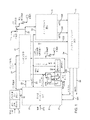
図1において、符号11は、比較的高濃度の生物起源炭素及び比較的低濃度の他の非炭素物質を伴う非生物起源炭素を含む都市固形廃棄物(MSW)原料に由来する高生物起源濃度のフィッシャー-トロプシュ液体を製造するための全体システムを示す。
In FIG. 1,
システム11の前部には、非生物起源由来の炭素物質及び非炭素物質をMSWから除去して、MSWに見られる比較的高濃度の生物起源炭素及び比較的低濃度の他の非炭素物質を伴う非生物起源炭素を含む分離された原料を製造するためのMSW原料製造設備(全体的に符号13で示す)が設けられている。
At the front of
好ましい実施形態では、原料処理設備13は入ってくるMSWを処理し、物質を以下のカテゴリーに分ける:
・燃料に転化するために使用される、MSW流から選別された原料物質;
・鉄及び非鉄金属、厚紙、プラスチック、紙、及び選別され商品市場に出荷され得るその他のリサイクル可能物質を含むがこれらに限定されない、回収可能物質;及び
・リサイクルされないか、又は原料として使用されない物質の残りであり、埋立地に送られ得る、残留物質。
In a preferred embodiment, feedstock processing facility 13 processes incoming MSW and separates materials into the following categories:
- Selected feedstock material from the MSW stream, which is used for conversion to fuel;
- Recoverable materials, including but not limited to ferrous and non-ferrous metals, cardboard, plastics, paper, and other recyclable materials that can be sorted and placed on the commodity market; and - Materials that are not recycled or used as raw materials. Residual material that is the remnant of and can be sent to landfills.
特に高密度ポリエチレン(HDPE)及びポリエチレンテレフタレート(PET)などのプラスチックを回収することによって、原料中の非生物起源の化石系炭素の割合は低減される。従って、原料処理設備は、ガス化してシンガスにすることができる高生物起源原料物質を提供するように機能する。上述の理由から、原料の生物起源含有率は、セルロース系燃料の経済的価値に重大な影響を及ぼす。 By recovering plastics, especially high density polyethylene (HDPE) and polyethylene terephthalate (PET), the proportion of non-biogenic fossil carbon in the raw material is reduced. The feedstock processing facility thus functions to provide a high biogenic feedstock material that can be gasified into syngas. For the reasons stated above, the biogenic content of feedstocks has a significant impact on the economic value of cellulosic fuels.
原料処理ユニット13において、廃棄物質は、プロセスにおいて有用でないか、又はその効率を低下させる可能性がある物質を除去するために、寸法決めされ、分離され、かつ処理され得る。例えば、システムは、金属、無機物質、及び食品廃棄物又は農産物などの湿った物質を除去する。そのような物質は、例えば、リサイクルされてもよいし、又は埋立地に送られてもよい。生物起源含量が高い食品廃棄物及び農産物の一部は、乾燥され、他の物質とともに原料流に添加し戻され得る。 In the raw material processing unit 13, waste materials may be sized, separated and treated to remove materials that are not useful in the process or that may reduce its efficiency. For example, the system removes metals, inorganic materials, and wet materials such as food waste or produce. Such material may, for example, be recycled or sent to a landfill. Some of the food waste and agricultural products with high biogenic content can be dried and added back to the feed stream along with other materials.
この図に示すように、原料処理設備13は、図1に示すシステムの他の部分と物理的に別個の設備とすることができる。一例として、原料処理設備13は、同時係属中の米国特許出願第14/138,635号(都市固形廃棄物をエタノールに転化するためのプロセスにおける生成物再循環ループ(Product Recycle Loops in Process for Converting Municipal Solid Waste into Ethanol))に記載されているようなものであり、その開示は参照により本明細書に組み込まれる。 As shown in this figure, the feedstock processing facility 13 can be a physically separate facility from the rest of the system shown in FIG. As an example, the feedstock processing facility 13 is described in co-pending U.S. Patent Application No. 14/138,635 (Product Recycle Loops in Process for Converting Municipal Solid Waste to Ethanol). Municipal Solid Waste into Ethanol), the disclosure of which is incorporated herein by reference.
原料は組成が大きく異なる可能性があるが、原料を再循環して選別した後に残存する物質の組成の例示的な公称値を以下の表1に列挙する。 Although the feedstock can vary widely in composition, exemplary nominal values for the composition of the material remaining after recycling and screening the feedstock are listed in Table 1 below.

好ましくは処理、貯蔵及び取り扱いプロセスによって除外される残留物質は、例えば、金属、岩石、土、ガラス、コンクリート、及びPVCを含むことができる。通常の条件下では、不合格率は、物質処理ユニットへの総供給率の約10%~約55%の間で実行される。しばしば、不合格物は原料から個別に分離され、容器に預けられ、埋立地又はコンポスト化作業に輸送されるか、又は適用される政府規制に従ってリサイクリング又はゴミ回収所に送られる。 Residual materials that are preferably removed by treatment, storage and handling processes can include, for example, metals, rocks, soils, glass, concrete, and PVC. Under normal conditions, the rejection rate runs between about 10% and about 55% of the total feed rate to the material processing unit. Frequently, the rejects are separated from the raw material separately, deposited in containers, and transported to a landfill or composting operation, or sent to a recycling or garbage collection site in accordance with applicable governmental regulations.
重要なポイントは、全体的に符号17で示されるバイオ精製所に、都市固形廃棄物からの比較的高濃度の生物起源炭素及び比較的低濃度の他の非炭素物質を伴う非生物起源炭素を含む流れ15を供給することである。実際には、比較的高濃度の生物起源炭素は、約80%までの生物起源炭素である。
An important point is that the biorefinery, generally designated 17, has relatively high concentrations of biogenic carbon from municipal solid waste and non-biogenic carbon with relatively low concentrations of other non-carbon materials. to provide a
図1に示すシステムの残りの部分は、処理された原料の流れ15をフィッシャー-トロプシュ液体の流れ520及び524に転化するバイオ精製所17である。特に注目すべきは、高生物起源濃度のフィッシャー-トロプシュ液体が、入力流15と同じ比較的高濃度の生物起源炭素を含むことである。換言すれば、その製造プロセスにおいて高率の非生物起源炭素はフィッシャー-トロプシュ液体に添加されず、実際には、その一部は取り除かれ得る。
The remainder of the system shown in FIG. 1 is biorefinery 17 which converts processed
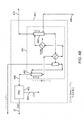
図示された実施形態では、バイオ精製所17は、全体的に符号21で示されるガス化システムを含み、場合によっては本明細書において、MSW由来の原料をシンガスに転化し、さらにそのシンガスを以下で説明するような炭化水素改質器(HR)を介して処理し、高生物起源含量のシンガスを生成する、ガス化アイランド(GI)を指す。ガス化システム21は、再循環された炭化水素生成物及び中間生成物をそれぞれHRに運ぶ流れ231及び233を受け取ることに留意されたい。また、GI21は、以下で詳細に説明されるその段階1及び段階2に再循環されたCO2を運ぶ流れ27を受け取る。以下でもさらに説明するように、再循環されたCO2は、GI21の蒸気改質器内の水性ガスシフト反応を緩和するために、また計器、計器システム及びMSW供給器システムのためのパージガスとして使用される。さらに、GI21は、酸素の流れ273及びF-T排ガスの流れ25を受け取る。
In the illustrated embodiment, the bio-refinery 17 includes a gasification system, indicated generally at 21, optionally herein for converting MSW-derived feedstock into syngas, which is further processed as follows: refers to the gasification island (GI), which is processed through a hydrocarbon reformer (HR) as described in , to produce high biogenic content syngas. Note that
ガス化アイランド21では、一般的に言えば、生物起源炭素は、蒸気改質、準化学量論的炭素酸化及び炭化水素改質の組み合わせによって、生物起源シンガスに転化される。CO、H2及びCO2を含むシンガス生成物は、図示された実施形態では流れ29によって運ばれる。GI21で起こるガス化反応については、以下でさらに説明する。
At
シンガス流29は、以下でより詳細に説明するように、シンガス調整システム41で処理され、シンガス供給流31をF-T反応器システム33に提供する。シンガス調整システム41は、CO2をGI21に再循環し戻すためのCO2再循環流27を提供することに留意されたい。
F-T反応器システム33からの出力は、ともにF-T炭化水素である中間フィッシャー-トロプシュ液体(MFTL)の流れ520及び重質フィッシャー-トロプシュ液体(HFTL)の流れ540を含有するF-T流体を含む。以下に説明するように、未反応のシンガスはF-T反応器33で再循環され得る。さらに、F-T反応器システム33の出力は、前述のF-T排ガスの流れ25を含む。
The output from the
バイオ精製所には、アップグレーディングに必要な水素を調整されたシンガスから除去するための水素回収システムが含まれる。調整されたシンガスの一部は、コンビネーション膜/PSAユニットを通って流れ、アップグレーディングユニット用の高純度水素流を生み出す。膜からの回収された水素(透過物)はPSAユニットに供給され、残留物はバイパスシンガスと組み合わされ、FT反応器に供給される。回収された水素は、比較的高純度の水素流(>99.5%H2)が製造されるPSAユニットに供給され、PSA不合格流は、不合格シンガスを回収するために、シンガス圧縮器の吸入口に送られる。 The biorefinery includes a hydrogen recovery system to remove the hydrogen required for upgrading from the conditioned syngas. A portion of the conditioned syngas flows through a combination membrane/PSA unit to produce a high purity hydrogen stream for the upgrading unit. The recovered hydrogen from the membrane (permeate) is fed to the PSA unit and the retentate is combined with the bypass syngas and fed to the FT reactor. The recovered hydrogen is fed to a PSA unit where a relatively high purity hydrogen stream ( >99.5% H2) is produced and the PSA reject stream is sent to a syngas compressor to recover the rejected syngas. is sent to the inhaler of
図1のバイオ精製所17は、F-Tシステム33からF-T流体を受け取るためのアップグレーディングシステム54をさらに含む。図示された実施形態では、重質フィッシャートロプシュ液体(HFTL)の流れ540及び中間フィッシャートロプシュ液体(MFTL)の流れ520の両方が、アップグレーディングシステム54に供給される。アップグレーディングシステム54からのF-T液体の出力液体は、図示された実施形態では、流れ58によって運ばれる。実際には、F-T液体は、ナフサ、ディーゼル、合成パラフィンケロシン(SPK)、イソアルカン、酸素化物及びオレフィンを伴う重質アルカン、又はこれらの全成分の組み合わせを含むことができる。アップグレーディングシステム54からの他の出力は、ナフサの前述の流れ231及びオフガスの流れ233である。
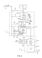
ガス化アイランドシステム21は、図2に詳細に示すように、3段階ガス化プロセスを実施する。好ましい実施形態では、3段階ガス化プロセスは以下を含む:
a.段階1-蒸気改質;
b.段階2-蒸気改質後の未反応炭素をガス化するための準化学量論的炭素酸化;及び
c.段階3-炭化水素改質。
a. Stage 1 - steam reforming;
b. Stage 2—substoichiometric carbon oxidation to gasify unreacted carbon after steam reforming; and c. Stage 3 - Hydrocarbon reforming.
図示された実施形態では、段階1のガス化ユニット251は、処理された原料の流れ15を選択的に受け取り、シンガスの流れ254を製造する。ガス化ユニット271は、ガス化ユニット251から未反応の炭素を受け取り、シンガスの流れ277を製造する。シンガス蒸気254及び277は組み合わされ、シンガス流219を形成する。
In the illustrated embodiment, the stage one
図示された実施形態では、全体的に符号211で示されるガス化ユニットはそれぞれ、全体的に符号251及び271で示される段階1及び2のユニットを含む。ユニット251はガス化が達成される蒸気改質器であることが理解できる。さらに、ユニット271は、段階1のガス化からの未反応の炭素が化学量論的にシンガスに転化される炭素酸化システムであることが理解できる。またガス化アイランド21において、炭化水素改質は、全体的に符号215で示される炭化水素改質システムによって第3段階で提供される。
In the illustrated embodiment, the gasification units, generally designated 211, include stage 1 and 2 units, generally designated 251 and 271, respectively. It can be seen that
図示された実施形態では、段階1のガス化ユニット251は、処理された原料の流れ15を選択的に受け取り、シンガスの流れ254を製造する。ガス化ユニット271は、ガス化ユニット251から未反応の炭素を受け取り、シンガスの流れ277を製造する。シンガス蒸気254及び277は組み合わされ、シンガス流219を形成する。また、ガス化ユニット211は、再循環されたCO2の流れ27を受け取る。ガス化ユニット211では、流れ27中の回収された高生物起源CO2は、準化学量論的炭素酸化ユニット271及び炭化水素改質器215において、床物質(bed material)を流動化させ、水性ガスシフト反応を緩和し、蒸気改質器251内の器具をパージする手助けをするために使用され得る。また、流れ27中の回収された高生物起源CO2は、図のように、処理された原料の流れ15に添加することができる。
In the illustrated embodiment, the stage one
上述したように、図2の実施形態におけるガス化ユニット211は、蒸気改質器251及び準化学量論的炭素酸化ユニット271を含む。処理された原料の蒸気15を最初に受け取るのは蒸気改質器251である。また、酸素の蒸気273を最初に受け取るのも蒸気改質器251である。好ましくは、蒸気改質器251は、間接熱源253を含む。蒸気改質器251からの出力流は、シンガスの流れ254及び固体の流れ256を含む。シンガス流254は、流れ219とともに炭化水素改質ユニット215に運ばれる。主として灰分と細かい炭化物からなる固体流256は、準化学量論的炭素酸化ユニット271に運ばれる。
As noted above,
好ましい実施形態では、蒸気改質器251は、流動床媒体として過熱された蒸気、CO2及びO2を利用する流動床システムである。別の実施形態では、蒸気及びO2のみが流動床媒体として使用される。好ましくは、外部燃焼間接ヒーター253は、改質器の床温度を維持し、ガス化プロセスで必要とされる吸熱反応を支援するためのエネルギーの大部分を提供する。プロセスガス流は、一連のサイクロンを介して蒸気改質器251を出ることができる。好ましくは、内部サイクロンが同伴された床媒体の大部分を分離して改質器の流動床に戻しながら、準化学量論的炭素酸化ユニット271においてシンガスにさらに転化するために、第2の外部サイクロンが未反応の炭化物を集める。好ましくは、蒸気改質器の間接ヒーターからの煙道ガスは、煙管ボイラーで使用され、プラントで使用するための蒸気を生成する。
In a preferred embodiment, the
図示された炭化水素改質器ユニット215は、シンガス流219を受け取り、微量成分とともにCO、H2及びCO2を含むシンガスの上述の一次流29を製造する。さらに、炭化水素改質器ユニット215は、酸素の流れ273及びF-T排ガスの流れ25を受け取る。最後に、炭化水素改質器ユニット215は、上述のナフサの流れ231及びオフガスの233を受け取る。
The illustrated
炭化水素改質器ユニット215は、2200°Fを超える温度で炭化水素を熱解離させることによって生物起源炭素を回収するように動作する。炭化水素改質器のための熱は、一酸化炭素及び水素の酸化によって提供される。これらの反応は発熱性であることに留意されたい。
The
図2の実施形態における炭化水素改質器ユニット215は、シンガス冷却セクション225を含む。シンガス冷却セクションは、例えば、放射スラッギング冷却器又はリサイクルシンガススラッギングクエンチャーを含むことができる。
The
好ましい実施例では、炭化水素改質ユニット215は、1800°Fから3000°Fの範囲で作動する酸素ガスバーナー/ミキサーを有する耐火物内張容器であり、ガス流中のタールを含む全ての炭化水素化合物をシンガスに転化し、硫黄化合物をH2Sに転化し、水性ガスシフト反応が平衡に近づくことを保証する。炭化水素改質ユニット215では、F-T排ガスが、F-T反応ループからパージされ、純化システムのオフガス及び蒸発したナフサの流れ231をCO及びH2に転化し戻す。
In a preferred embodiment, the
準化学量論的炭素酸化ユニット271は、固体流256を受け取ることに加えて、再循環されたCO2流の流れ27及び酸素の流れ273を受け取る。炭素準化学量論的酸化ユニット271における加熱は、未反応炭素の準化学量論的酸化によって提供される。低圧蒸気の流れ275は、準化学量論的炭素酸化ユニット内で過熱され、段階1及び段階2の両方のガス化のための流動化蒸気として使用される。準化学量論的炭素酸化ユニット271の出力は、シンガス流277であり、図示された実施形態では、蒸気改質器251からのシンガス流254と合流して、炭化水素改質器ユニット215に供給されるシンガス流219を形成する。
Substoichiometric
好ましい実施形態では、準化学量論的炭素酸化ユニット271は、流動床を利用し、そこでは酸素が流動化蒸気及びCO2とともに添加され、細かい炭化物をさらにシンガスに転化する。準化学量論的炭素酸化ユニット271内で生成され、それを通過したガスは、外部サイクロンを通過し、一次シンガス流219に再び入る。好ましくは、サイクロンで除去された灰分は、現地外処分のために冷却され、収集サイロに輸送される。準化学量論的炭素酸化ユニット271の流動床に沈められた熱交換器は、流動床蒸気改質器251及びユニット271自体の流動床で使用するために、低圧蒸気を1100°Fに過熱することによっていくらかの熱を除去する。
In a preferred embodiment, substoichiometric
図2のシステムの動作では、蒸気改質器251の流動床内で、外部燃焼ヒーターが、循環床媒体及び容器に入る原料を急速に加熱する。ほぼ直ちに、原料は乾燥及び熱分解を受け、それによってガス状及び固体(炭化物)生成物を作り出す。ガス状の熱分解生成物は水性ガスシフト反応を受け、固体炭化物質の同時の蒸気改質とともに、主にH2、CO、CO2、及び幾つかの炭化水素からなるシンガスを製造する。残りのほとんどの炭化物は、過熱蒸気及び酸素と反応してシンガスを製造する。蒸気改質器を出る炭化物は、サイクロンを介して分離され、追加のガス化及び転化のために準化学量論的炭素酸化ユニット内に落とされる。蒸気改質器及び準化学量論的炭素酸化ユニットは、内部及び外部のサイクロンを利用して、プロセスガス流中に同伴されるようになる床媒体を分離して保持する。蒸気改質器251及び準化学量論的炭素酸化ユニット271から、シンガスは流れ219を介して炭化水素改質器ユニット215に流れ、残りの炭化物、炭化水素及びタールをシンガスに転化する。
In operation of the system of FIG. 2, within the fluidized bed of the
上述したように、炭化水素改質器ユニット215の出力はシンガス流29であり、それは、図3とともに説明されるシンガス調整システム41に供給される。
As mentioned above, the output of
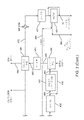
図3に示すように、全体的に符号41で示されている例示的なシンガス調整システムは、一次シンガス流29を受け取り、その流れを調整してF-T反応器へのガス状供給流31を生成する。図示された実施形態では、シンガス調整システム41は、連続的な流体連通状態で、廃熱回収のためのシンガス熱回収蒸気発生器(HRSG)ユニット411と、シンガススクラバユニット421と、シンガス圧縮器431と、一次ガード床436と、水性ガスシフト反応器441と、アンモニア除去ユニット446と、二次ガード床451と、CO2/H2S除去システム461と、を含む。CO2/H2S除去システム461の1つの出力は、図示された実施形態では、シンガス供給流470である。CO2/H2S除去システム461の別の出力は、再循環されたCO2の流れ27である。
As shown in FIG. 3, an exemplary syngas conditioning system, generally designated 41, receives a
図からわかるように、蒸気はプロセス内の幾つかの供給源から生成される。HRSGは、蒸気改質器ユニット251の間接燃焼ヒーターユニット253で生成された煙道ガスから蒸気を回収する。蒸気はまた、ガス化アイランドを離れるシンガス流29から熱を回収するHRSGユニット411で生成され、蒸気は発電ボイラーで生成される。全ての3つの供給源からの蒸気を組み合わせて過熱して、シンガス圧縮器(すなわちユニット431)蒸気タービン又は蒸気タービン発電機(図1)の何れかにおける動力流体として使用される中圧蒸気を提供する。組み合わされた中圧蒸気は、外部ヒーターを燃焼するのに使用される天然ガスの量に応じて、MSW供給に等しい生物起源含量を有することができる。好ましい実施形態では、生成されたシンガスの一部は、ガスタービン/蒸気タービン(複合サイクル発電プラント)に供給されて、プラントの電気需要を供給するために使用される高生物起源含量の動力を生成する。別の実施形態では、シンガスの全てを使用して生物起源の動力用の蒸気を生成し、シンガス圧縮器ユニット431を蒸気タービン駆動装置で駆動する。
As can be seen, steam is produced from several sources within the process. The HRSG recovers steam from the flue gas produced by the indirect fired
シンガススクラバユニット421は、シンガス流420及び腐食性又は他の適切なアルカリ性溶液の流れ424を受け取る従来のガススクラビング装置である。スクラバユニット421から除去された液体は、廃水処理システムに搬送され得る酸性水流426を含む。酸性水は、例えば、灰分粒子、酸、水銀、及びシンガスから除去される塩酸(HCl)及び硫化水素(H2S)などの酸性化合物などの望ましくない汚染物質を含み得る。従って、シンガススクラバユニット421は、下流の設備に潜在的にダメージを与え、F-T合成触媒の性能に影響を及ぼす可能性のある汚染物質を除去するために設けられることが理解されよう。
The
好ましくは、シンガススクラバユニットは、3つの主要なセクション-ベンチュリスクラバ、充填タワーセクション、及び直接接触クーラーセクション、を有する。シンガスクエンチクーラーが利用される場合、シンガススクラバユニットを離れる洗浄されたシンガスの約半分は、クエンチブロワーを介して炭化水素改質器クエンチクーラーに循環し戻され、一方、残りの半分は、F-T合成プロセスの要件を満たすために、シンガス圧縮器431内で圧縮される。放射スラッギングクーラーが使用される場合、リサイクルガスブロワーは必要なく、スクラバ内への流れはガス化アイランド21を離れる流れに等しい。シンガススクラビングは、同時係属中の米国特許出願第14/138,635号においてさらに記載され、その開示は参照により本明細書に組み込まれる。スクラブされたシンガスは、流れ428で搬送される。
Preferably, the syngas scrubber unit has three main sections--a venturi scrubber, a charged tower section and a direct contact cooler section. When a syngas quench cooler is utilized, about half of the cleaned syngas leaving the syngas scrubber unit is recycled back to the hydrocarbon reformer quench cooler via the quench blower, while the other half is It is compressed in
図示された実施形態では、シンガス圧縮器段431は、シンガス流の少なくとも一部を含む圧縮器入口流の圧力を所定のレベルに上昇させるために直列に配置された1つ以上の従来の圧縮器段433を含み、それにより圧縮されたシンガス流436を産出する。実際には、シンガス流434の最終圧力は、F-T合成プロセスのプロセス要件を満たすために、約400psigから約600psigの範囲であり得る。好ましくは、最終段を除く全ての段の後で圧縮熱を中間クーラーで除去し、全ての凝縮水を集め、回収のために廃水処理プラントに送る。圧縮器の出口は、一次ガード床436に高温で送られ、ここで任意のCOS及びHCNがH2S及びNH3に加水分解され、次いでシフト反応器441に送られる。
In the illustrated embodiment, the
一実施形態では、シンガス圧縮器駆動装置は、プロセス要件のために低圧で抽出された蒸気の一部で過熱された高圧蒸気によって駆動される抽出/凝縮タービンである。また、F-T再循環圧縮器(図5のユニット511)は、シンガス圧縮器シャフト上にあり、シンガス圧縮器蒸気タービン駆動装置によって駆動することができる。別の実施形態では、シンガス圧縮器は、高生物起源動力を製造するためにシンガスを燃料として使用する複合サイクル発電プラントで生成される動力からエネルギーを与えられる電気モーターによって駆動される。
In one embodiment, the syngas compressor drive is an extraction/condensation turbine driven by high pressure steam superheated with a portion of the low pressure extracted steam for process requirements. Also, the FT recycle compressor (
図3にも示しているように、水性ガスシフト反応器441は、加圧された一次シンガス流440の一部を受け取り、出口流450の必要とされるH2/CO比率が満たされるまで、水性ガスシフト反応を介して蒸気及びCOの一部をH2及びCOにシフトさせる。続いて、加圧された一次シンガスの副流442は、水性ガスシフト反応器441をバイパスすることができ、水性ガスシフト反応器441からの出口流450と再び組み合わさることができる。水性ガスシフトユニットで高圧蒸気が生成され、シフト反応の熱を除去する。生成された蒸気は、反応器に供給されるシンガス流440内に供給し戻され、シフト反応用の水素源を提供する。必要とされる追加の蒸気は、プラント蒸気システムによって供給することができる。
As also shown in FIG. 3, the water
図3の実施形態では、水性ガスシフト反応器441からのシンガスの出口流450は、従来のアンモニア除去ユニット446に搬送される。アンモニア除去ユニット446では、シンガスは、吸収されたアンモニアとともに過剰の水が凝縮するまで冷却される。次いで、シンガスは、流れ448として凝縮器446を離れる。凝縮器446からの酸性水は、廃水処理システムに搬送することができる。流れ448は二次ガード床451の入口に搬送され、そこで揮発したHgが除去される。
In the embodiment of FIG. 3, the
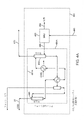
図3にさらに示すように、二次ガード床451からの加圧された一次シンガスは、流れ460としてCO2/H2S除去システム461に搬送される。CO2/H2S除去システム461は、図4A及び図4Bとともにさらに説明される。CO2/H2S除去システム461の1つの出力は、硫黄の流れ464である。別の出力は、硫黄が除去されたシンガスの流れ470である。第3の出力は、CO2再循環流27である。
As further shown in FIG. 3, the pressurized primary syngas from
図3の図示された実施形態では、シンガス供給流470はH2S及びアルシンガード床471に搬送され、次いでH2回収ユニット481に搬送される。
In the illustrated embodiment of FIG. 3 ,
H2S/アルシンガード床からのシンガスは、水素回収ユニット481に流入する。水素回収ユニット481は、以下に説明するように、水素化分解アップグレーディングプロセスに必要とされる高純度H2の蒸気482を抽出する。H2回収ユニット481の出力は、F-T反応器33へのシンガス供給流31である。水素回収ユニット481からの第3の出力は、不合格シンガスの流れ483である。流れ483は、流れ428に合流するように再循環することができる。
The syngas from the H 2 S/arsine guard bed enters
好ましい実施形態では、水素回収ユニット(HRU)481は、膜と圧力変動吸着(「PSA」)の組み合わせシステムを用いてH2を抽出する。HRU膜保持ガスは、バルクシンガス流と再混合され、F-T反応器に送られる。HRU PSAパージガスは、シンガス圧縮器431の吸引口に送られ、純化されたH2流482は、アップグレーディングに送られる。
In a preferred embodiment, the hydrogen recovery unit ( HRU ) 481 extracts H2 using a combined membrane and pressure swing adsorption (“PSA”) system. The HRU membrane retention gas is remixed with the bulk syngas stream and sent to the FT reactor. The HRU PSA purge gas is sent to the suction of the
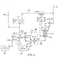
図5に示すように、F-T液体を生成するシステム33は、シンガス供給流31を受け取る。このシステムは、1つ以上のF-T反応器533を含み、上述したように、F-T液体及びF-T排ガスを含む流体出力流535を提供する。F-T反応器出力流535は、全体的に符号500で示される熱分離システムに供給され、F-T液体をその重質F-T液体(HFTL)、中間FT液体(MFTL)、水及びF-T排ガスに分離する。
As shown in FIG. 5,
図5に示すような好ましい実施形態では、熱分離システム500は、2つの凝縮器501及び531、並びに2つの分離器503及び504を含む。HFTL分離器503は、それぞれ出口518及び520を有する。実際には、凝縮器501は、調節された熱水ループを冷却媒体として用いて作動し、F-T水及びMFTL液体部分からHFTL液体部分を凝縮及び分離する。MFTL水とFT排ガスはともに、蒸気相のままである。HFTL流は、さらなる処理のためのタンク521に貯蔵するために、出口520によって運ばれる。実際には、HFTL流520は、主として、室温で固体の重質炭化水素ワックスからなる。これらのワックスは、固化を防ぐために230°Fを超えて温かく保たれる。
In a preferred embodiment, as shown in FIG. 5,
また図5に示すように、熱分離システム500は、HFTL分離器503からの流れ518を介してF-T水及びMFTLを受け取る第2凝縮器531を含む。実際には、第2凝縮器531は、冷却水を使用して、未反応シンガス及び非凝縮性炭化水素(すなわち、メタンなど)からF-T水及びMFTLを凝縮及び分離する。凝縮されたF-T水及びMFTL流相は、第2分離器504で分離され、MFTL流は流れ540を介して貯蔵ユニット522に送られ、F-T水は流れ542を介して廃水処理に送られる。
Also shown in FIG. 5,
さらに図5に示すように、F-T排ガスは、流れ537を介してF-T反応器533に再循環することができる。図示された実施形態では、F-T排ガスは、MFTL分離器504で分離され、流れ550によって圧縮器511に運ばれ、その出力はシンガス再循環ライン537に搬送される。再循環圧縮器511の前に、パージ流552が流れ550から分岐する。パージ流552は、再循環シンガス中の炭化水素含量を制御するために流れ25を介して炭化水素改質器215に向かい(図2)、また、再循環シンガスからの不活性ガスをパージするために発電ボイラーに向かうことができる。
Further, as shown in FIG. 5, FT exhaust gas may be recycled to
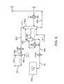
図6は、図1のアップグレーディングシステム54の一実施形態の例を示す。より詳細には、この図は、図5のシステムから精製F-T液体を製造するシステムを示す。図示されたシステムは、前述のタンク521及び522によって供給される水素化分解装填容器524(図5)から液体を受け取る水素化分解装置反応器ユニット643を含む。好ましい実施形態では、水素化分解装置反応器ユニット643は、HFTL及びMFTL炭化水素流を輸送燃料(SPK又はディーゼル)にアップグレードする高温、高圧触媒プロセスを採用する。アップグレーディングの程度が低いため、水素化処理と水素化分解とは1つの反応器で生じる。オレフィン及びアルコールは最初に飽和化され、次いでアルカンがSPK製品の範囲に分解される。プロトン化されたシクロプロパン中間体を伴う水素化分解機構は、直鎖状生成物とともに異性体生成物を形成する。水素化分解装置反応器ユニット643において、供給混合物は、より短い鎖状炭化水素に転化するための一連の触媒床を通過する。
FIG. 6 illustrates an example embodiment of the
別の実施形態では、MFTLは予め分留され、炭化水素改質器の塔頂の軽質分を除去することができる:次いで、重質分がHFTLとともに、アップグレーディングのために水素化分解装置に搬送される。この実施形態は、水素化分解装置に流れる流れから大部分の酸素化物を除去し、水素化分解装置の水素化処理負荷を軽減する。 In another embodiment, the MFTL can be pre-fractionated to remove the light ends overhead of the hydrocarbon reformer; be transported. This embodiment removes most of the oxygenates from the stream flowing to the hydrocracker and reduces the hydroprocessing load of the hydrocracker.
図6にさらに示すように、水素化分解装置反応器ユニット643は、全体的に符号701で示される炭化水素熱分離システムに供給される出力流れ644を提供し、その分解物は、一連の熱交換器及び分離容器を用いて、冷却され、凝縮され、2つの分離した重質及び軽質分解物流に分離される。
As further shown in FIG. 6, the
炭化水素熱分離システム701の図示された実施形態では、分解物は供給/流出熱交換器702で冷却され、重質分解物は重質分解物分離器703において軽質分解物から分離される。重質分解物分離器703から、重質分解物及び軽質分解物は、流れ704及び750によって分留器853に送られる。さらに、重質分解物の一部は、水素化分解装置643に再循環されて、始動中及び分留塔が誤動作している場合に水素化分離装置内への材料の流れを維持することができる。
In the illustrated embodiment of hydrocarbon
図示された実施形態では、生成された水及び水素から軽質分解物を分離するために、軽質分解物分離器705が設けられる。分離された軽質分解物は、流れ750によって分留器853に送られる。重質分解水は、ライン706によって、処理用のバイオ製油所の廃水処理プラントに送られる。分離された水素ガスは、流れ708、741及び742によって再循環するために送られる。新鮮な水素は、流れ741によってシステム内に導入される。
In the illustrated embodiment, a light cracks
ここで、図6の分留プロセスについて、より詳細に説明する。前述したように、分留器853は、重質分解液の流れ704及び軽質分解液の流れ750を受け取る。分留器853の目的は、重質分解物留分及びナフサ留分からSPK又はディーゼルを分離することである。副ドロー流856は、ストリッパー塔857内に供給され、SPK/ディーゼル供給から軽質分を除去し、SPK/ディーゼル生成物の最終的な清浄化及び回収を提供する。分留器853では、流入する重質及び軽質分解物流を合流させ、分留塔での最初の分離のために天然ガス燃焼ヒーターによって加熱する。好ましくは、分留器853は直接蒸気注入を使用し、高温リボイラー構造を利用することなく、高沸点炭化水素から低沸点炭化水素を除去する。
The fractionation process of Figure 6 will now be described in more detail. As previously described,
分留器853からの出力は、再循環可能な炭化水素生成物を運ぶ塔頂流23を含む。好ましくは、塔頂流823は凝縮器ユニット860に供給され、そこでその流れは、3つの流れ:主分留器(「MF」)水流862、前述の軽質相(ナフサ)流231、及びオフガス流233、に凝縮及び分離される。実際には、ナフサの一部を分留器53内に還流し戻すことができ、かつ/又は、炭化水素改質器内に注入するために一部をナフサ気化器に送ることができる。オフガス流233は、再処理のために、オフガス圧縮器によって炭化水素改質器に再循環される。分留塔853からの底部は、追加の水素化分解のために、流れ855によって水素化分解装填容器524にポンプ輸送される。水は処理用のバイオ精製所の廃水処理プラントに送られる。
The output from
分留器OH分離器からのナフサは、ナフサ気化器内にポンプ輸送され、そこで低圧蒸気を用いて気化される。次いで、ナフサ蒸気は、回収のために図2の炭化水素改質器215に流入する。分留塔の塔頂圧力は、オフガスの圧縮器排出速度で浮動する。オフガス圧縮器は、分留器の塔頂分離器のオフガスをナフサ気化器の排出口に移動する原動力を提供する。次いで、組み合わされた流れは、炭化水素改質器に流入する。
The naphtha from the fractionator OH separator is pumped into the naphtha vaporizer where it is vaporized using low pressure steam. The naphtha vapor then enters the
分留器853の上部からの流れ856によって引き出されるSPK生成物は、最終生成物を分離するために生成物ストリッパー塔857に送られる。生成物ストリッパー塔857への熱は、例えば、天然ガス燃焼の生成物ストリッパーリボイラーによって提供される。生成物ストリッパーの塔頂流は、分留器853に再循環し戻される。底流800は冷却され、流れ58を介してSPK生成物として貯蔵ユニット803に送られる。
The SPK product withdrawn by
図4Aに示すように、例示的なCO2/H2S除去システム461の一実施形態は、流れ460を受け取る硫黄除去ユニット463を含む。硫黄除去ユニット463の1つの出力は、硫黄の流れ464である。除去ユニット463の別の出力は、硫黄が除去されたシンガスの流れ466である。
As shown in FIG. 4A, one embodiment of an exemplary CO 2 /H 2
シンガス流466は、全体的に符号491で示されるアミン溶媒システムに供給される。図示された実施形態では、アミン溶媒システム491Aは、向流関係で接続された吸収ユニット493と再生ユニット495とを含む。再生ユニット493の出力は、上述したシンガス供給流470である。吸収ユニット495の出力は、上述した再循環CO2の流れ27である。
図4Aの好ましい実施形態では、吸収ユニット493は、循環アミン/水溶液との接触によってCO2が除去される塔である。この実施形態では、アミン吸収器は、硫黄除去ユニットが実行されている場合に、流れ466からH2Sを除去することができる。処理されたシンガスを水洗して、同伴されたアミン溶液を除去する。好ましい実施形態では、溶媒吸収器493を離れる清浄なシンガスは、中圧(MP)飽和蒸気を用いて加熱され、流れ470としてガード床に送られ、F-T合成プロセス内に導入される前に微量H2S及びヒ素触媒毒を除去する。
In the preferred embodiment of FIG. 4A,
図4Bに示すように、別の例示的なCO2/H2S除去システム461はアミンユニットを含み、そこで、シンガス流460は、全体的に符号491Bで示されるアミン溶媒システムに供給される。図示された実施形態では、アミン溶媒システム491Bは、向流関係で接続された吸収ユニット493と再生ユニット495とを含む。再生ユニット495の出力は、硫黄除去ユニット463に供給される。吸収ユニット493の出力は、上述したシンガス供給流470である。この実施形態では、吸収ユニット493は、循環アミン/水溶液との接触によってCO2及びH2Sが除去される塔である。次いで、処理されたシンガスを水洗して、同伴されたアミン溶液を除去し、流れ470として最終ガード床に送る。
As shown in FIG. 4B, another exemplary CO 2 /H 2
図4Bの実施形態では、再生器の塔頂出力流466は、硫黄除去ユニット463に供給され、そこで、H2Sは不合格CO2流から除去される。硫黄除去ユニット463の1つの出力は、上述した再循環CO2の流れ27及び硫黄の流れ464である。硫黄除去ユニットからの塔頂CO2不合格流の一部は圧縮され、ガス化アイランドに再循環し戻され、過剰分は大気に排出される。
In the embodiment of FIG. 4B, the regenerator
図4A及び図4BにおけるCO2/H2S除去システムの動作において、吸収塔からの「リッチ」アミン(すなわち、CO2吸収後のアミン)は、リーン/リッチ交換器を通過し、次いでリッチ溶媒フラッシュドラム内にフラッシュする。CO及びH2に富むフラッシュガスは、シンガス圧縮器の吸引口に流入し、プロセスで再利用される。フラッシュされたリッチ液体流は、溶媒再生塔に流入する。溶媒再生器では、リッチ溶媒を蒸気リボイラーで加熱し、吸収されたCO2/H2Sを追い出す。溶媒再生器の底部から流出する「リーン」溶媒は、リーン/リッチ交換器及び溶媒クーラーを介して、再利用のために吸収器に再循環し戻される。溶媒再生器からの塔頂CO2不合格流の一部は圧縮され、ガス化アイランドに再循環し戻され、過剰分は大気に排出される。好ましくは、システムは、CO及びH2の損失を最小限に抑えながら、シンガス流中のCO2含量を<1mol%に、H2S含量を<5ppmvに低下させるように設計される。 In operation of the CO2 / H2S removal system in Figures 4A and 4B, the "rich" amine (i.e., amine after CO2 absorption) from the absorber tower passes through a lean/rich exchanger and then the rich solvent Flash into the flash drum. The CO and H2 rich flash gas enters the syngas compressor suction and is recycled in the process. The flashed rich liquid stream enters the solvent regeneration tower. In the solvent regenerator, the rich solvent is heated in a steam reboiler to drive off the absorbed CO2 / H2S . The "lean" solvent exiting the bottom of the solvent regenerator is recycled back to the absorber for reuse via a lean/rich exchanger and solvent cooler. A portion of the overhead CO2 reject stream from the solvent regenerator is compressed and recycled back to the gasification island and the excess is vented to the atmosphere. Preferably, the system is designed to reduce CO2 content to <1 mol% and H2S content to < 5 ppmv in the syngas stream while minimizing CO and H2 losses.
上記システムの全体的な動作において、MSWがガス化される際に複数の反応が起こる。主な反応は、炭化物(炭素)が蒸気と反応して主に水素(H2)、一酸化炭素(CO)、二酸化炭素(CO2)及び幾つかの炭化水素からなるシンガスを製造するときに、高温で生じる:
C+H2O→H2+CO
2C+O2→2CO
C+O2→CO2。
同時に、可逆的「水性ガスシフト」反応は、ガス化動作温度での平衡定数に基づくCO/H2O及びCO2/H2比を有する平衡状態に近づく:
CO+H2O⇔CO2+H2。
ガス化システムは、少なくとも以下のガス化反応が生じるように提供された条件で構成されてもよい:
C+H2O⇔H2+CO。
同時に、条件は好ましくは、以下の可逆的な「水性シフト」反応が主にガス化装置の温度によって決定される平衡状態に到達し、圧力が好ましくは大気圧付近であるように提供され得る:
CO+H2O⇔CO2+H2。
一次FT反応は、触媒の存在下で、シンガスをより高い分子量の炭化水素及び水に転化する:
nCO+(2n+1)H2→CnH2n+2+nH2O。
In the overall operation of the above system, multiple reactions occur as the MSW is gasified. The main reaction is when char (carbon) reacts with steam to produce syngas, which consists mainly of hydrogen (H2), carbon monoxide (CO), carbon dioxide ( CO2 ) and some hydrocarbons. , which occurs at high temperatures:
C+ H2O →H2 + CO
2C+ O2 →2CO
C+ O2 → CO2 .
At the same time, the reversible "water - gas shift" reaction approaches equilibrium with CO/ H2O and CO2 /H2 ratios based on the equilibrium constants at the gasification operating temperature:
CO + H2O <-> CO2 + H2.
The gasification system may be configured with conditions provided such that at least the following gasification reactions occur:
C + H2O <-> H2 + CO.
At the same time, conditions may preferably be provided such that the following reversible "aqueous shift" reaction reaches an equilibrium state determined primarily by the temperature of the gasifier and the pressure is preferably near atmospheric:
CO + H2O <-> CO2 + H2.
The primary FT reaction converts syngas to higher molecular weight hydrocarbons and water in the presence of a catalyst:
nCO+( 2n +1)H2→CnH2n + 2 + nH2O.
さらに、システムの全体的な動作に関し、ガス化アイランド21で製造されたシンガスは、F-T液体の効果的な製造及びアップグレーディングには不十分な水素量を有することに留意されたい。酸性シフト反応器441は、追加の水素を生成し、シンガス中のH2:CO比を約0.8から約2.0に増加させる。水性ガスシフト反応は、シンガス中のCO及びH2Oの一部をH2及びCO2に転化する。この反応は発熱性であり、酸性シフト触媒上で起こる。この反応は、H2Sがシンガス流中に依然として存在するため、「酸性シフト」である。多用途の蒸気及びシフト反応器441によって生成された蒸気は、シンガスと混合され、水性ガスシフト反応のための水を提供し、反応器における温度上昇を抑える。水素製造及びシンガスのH2:CO比は、シフト反応器周りのシンガス流の一部をバイパスすることによって制御される。シフト反応器の流出熱は、反応器流入シンガスと交換し、シフト反応器蒸気を生成し、かつボイラー給水を予熱することによって回収される。
Further, with respect to the overall operation of the system, it should be noted that the syngas produced at
上記システムによるMSWからの燃料の生成は、顕著な利点を有する。それは、非常に低い排出プロファイルを有するエネルギー効率の良いシステムを提供し、埋立地に入るMSWを低減し(従って、埋立地からの有害なメタンガス排出を劇的に低減し、かつ新しい又は拡大した埋立地の必要性を軽減し)、石油及び石炭由来の燃焼生成物の使用に伴う温室効果ガスを置換によって低減する。そのシステムは、セルロース系燃料の生物起源含量を増加させ、従って、このような燃料の価値を実質的に増加させる。 The production of fuel from MSW by the above system has significant advantages. It provides an energy-efficient system with a very low emissions profile, reduces MSW entering landfills (thus dramatically reducing harmful methane emissions from landfills, and reducing new or expanded landfills). reducing land requirements) and reducing greenhouse gases associated with the use of petroleum- and coal-derived combustion products through replacement. The system increases the biogenic content of cellulosic fuels, thus substantially increasing the value of such fuels.
例示的な実施形態は、特定の構造を参照して記載された。特定の実施形態及び実施例の前述の記載は、例示及び説明のみの目的で提示されており、本発明は先の特定の実施例によって例示されているが、それによって本発明を制限することは意図していない。 The exemplary embodiments have been described with reference to specific structures. The foregoing descriptions of specific embodiments and examples have been presented for purposes of illustration and description only, and the present invention is illustrated by, but not limited to, the foregoing specific examples. Not intended.
11 システム
13 MSW原料製造設備、原料処理設備(ユニット)
17 バイオ精製所
21 ガス化システム、ガス化アイランド
33 F-T反応器システム
41 シンガス調整システム
54 アップグレーディングシステム
211 ガス化ユニット
215 炭化水素改質システム、炭化水素改質器(ユニット)
225 シンガス冷却セクション
251 段階1のガス化ユニット、蒸気改質器
271 段階2のガス化ユニット、準化学量論的炭素酸化ユニット
411 シンガス熱回収蒸気発生器(HRSG)ユニット
421 シンガススクラバユニット
431 シンガス圧縮器
433 圧縮器段
436 一次ガード床
441 水性ガスシフト反応器
446 アンモニア除去ユニット
451 二次ガード床
461 CO2/H2S除去システム
463 硫黄除去システム
471 H2S及びアルシンガード床
481 水素回収ユニット
491 アミン溶媒システム
493 吸収ユニット
495 再生ユニット
500 熱分離システム
501 凝縮器
503 HFTL分離器
504 MFTL分離器
511 F-T再循環圧縮器
521 タンク
522 タンク、貯蔵ユニット
531 第2凝縮器
533 F-T反応器
643 水素化分解装置反応器ユニット
701 炭化水素熱分離システム
702 供給/流出熱交換器
703 重質分解物分離器
803 貯蔵ユニット
853 分留器
857 生成物ストリッパー塔
860 凝縮器ユニット
11 system 13 MSW raw material manufacturing equipment, raw material processing equipment (unit)
17 Bio-refinery 21 Gasification system,
225
Claims (14)
a)原料処理ステップにおいて、前記都市固形廃棄物から非生物起源由来の炭素物質及び非炭素物質を除去して、前記都市固形廃棄物から、比較的高濃度の生物起源炭素及び比較的低濃度の他の非炭素物質を伴う非生物起源炭素を含む原料を製造することと、
b)発電プロセスにおいて、前記原料処理ステップから製造された処理原料から得られたシンガスの一部を動力に転化し、ライフサイクル温室効果ガスの排出を低減することと、
c)バイオ精製所において、前記都市固形廃棄物からの比較的高濃度の生物起源炭素及び比較的低濃度の他の非炭素物質を伴う非生物起源炭素を維持しながら、処理原料をフィッシャー-トロプシュ液体に転化することと、
を含み、ステップc)が、
ガス化アイランドにおいて、処理原料からシンガス並びに灰分及び未反応炭化物を含む固体流を製造する蒸気改質;前記蒸気改質により製造された固体流の未反応炭化物をガス化してシンガスを生成する準化学量論的炭素酸化;及び前記蒸気改質ステップ及び前記準化学量論的炭素酸化ステップにおいて製造されたシンガスを受け取り、残りの炭化物、炭化水素及びタールをシンガスに転化する炭化水素改質を3段階で行うことによって前記生物起源炭素を、CO、H2、H2O及びCO2を含む生物起源シンガスに転化することと、
シンガス調整ユニットにおいて、前記ガス化アイランドからのシンガスを受け取り、前記ガス化アイランドにCO2を再循環させ、
F-T反応器において、前記シンガス調整ユニットからシンガスを受け取り、前記シンガスをフィッシャー-トロプシュ液体に転化することと、を含み、
前記フィッシャー-トロプシュ液体が、前記処理原料と同じ比較的高濃度の生物起源炭素を含む、プロセス。 Processes to produce Fischer-Tropsch liquids with a high biogenic carbon content derived from municipal solid waste containing carbon of plant origin (biogenic) as well as carbon of non-biogenic origin (fossil) There is
a) removing non-biogenic carbon and non-carbon materials from the municipal solid waste in a raw material processing step to produce a relatively high concentration of biogenic carbon and a relatively low concentration of biogenic carbon from the municipal solid waste; producing a feedstock containing non-biogenic carbon with other non-carbon materials;
b) in the power generation process, converting a portion of the syngas obtained from the processed feedstock produced from the feedstock processing step into power to reduce life cycle greenhouse gas emissions;
c) in a biorefinery, a Fischer-Tropsch process feedstock while maintaining a relatively high concentration of biogenic carbon from said municipal solid waste and a relatively low concentration of non-biogenic carbon with other non-carbon materials; converting to a liquid;
wherein step c) comprises
steam reforming, at a gasification island, to produce syngas and a solids stream containing ash and unreacted char from the treated feedstock ; semi-chemical gasification of the unreacted char of the solids stream produced by said steam reforming to produce syngas. stoichiometric carbon oxidation; and hydrocarbon reforming that receives the syngas produced in the steam reforming step and the substoichiometric carbon oxidation step and converts the remaining chars, hydrocarbons and tars to syngas. converting the biogenic carbon to biogenic syngas comprising CO, H2, H2O and CO2 by performing at
receiving syngas from said gasification island and recycling CO2 to said gasification island in a syngas conditioning unit;
receiving syngas from the syngas conditioning unit and converting the syngas to a Fischer-Tropsch liquid in an FT reactor;
A process wherein said Fischer-Tropsch liquid contains the same relatively high concentration of biogenic carbon as said feedstock.
a)原料処理設備であって、前記都市固形廃棄物から非生物起源由来の炭素物質及び非炭素物質を除去して、前記都市固形廃棄物から、比較的高濃度の生物起源炭素及び比較的低濃度の他の非炭素物質を伴う非生物起源炭素を含む原料を製造する、原料処理設備と、
b)前記都市固形廃棄物からの比較的高濃度の生物起源炭素及び比較的低濃度の非生物起源炭素を維持しながら、前記処理原料をフィッシャー-トロプシュ液体に転化するための、バイオ精製所であって、
前記バイオ精製所が、比較的高濃度の生物起源炭素を含む前記処理原料からシンガス並びに灰分及び未反応炭化物を含む固体流を製造する蒸気改質、前記蒸気改質により製造された固体流の未反応炭化物をガス化してシンガスを生成する準化学量論的酸化、及び前記蒸気改質ステップ及び前記準化学量論的炭素酸化ステップにおいて製造されたシンガスを受け取り、残りの炭化物、炭化水素及びタールをシンガスに転化する炭化水素改質を3段階で提供するガス化アイランド(GI)を含み、前記ガス化アイランドが、
前記処理原料を受け取り、CO、H2、H2O及びCO2を含むシンガスを製造し;
再循環された炭化水素生成物及び中間生成物を受け取り、生物起源化合物の炭化水素改質によって前記生物起源炭素を回収し;
再循環されたCO2を受け取るように構成された、バイオ精製所と、
c)前記ガス化アイランドからシンガスを受け取り、前記ガス化アイランドにCO2を再循環させるシンガス調整システムと、
d)前記シンガス調整システムからシンガスを受け取り、前記シンガスをフィッシャー-トロプシュ液体に転化するF-T反応器と、
を含み、
前記フィッシャー-トロプシュ液体が、前記処理原料と同じ比較的高濃度の生物起源炭素を含む、システム。 For municipal solid waste (MSW) treatment feedstocks containing relatively high concentrations of biogenic carbon (carbon from plants) and non-biogenic carbon (carbon from fossil sources) with relatively low concentrations of other non-carbon materials A system for producing a high biogenic carbon concentration Fischer-Tropsch (FT) liquid derived from
a) a feedstock processing facility for removing non-biogenic carbon and non-carbon materials from said municipal solid waste to produce a relatively high concentration of biogenic carbon and a relatively low concentration of biogenic carbon from said municipal solid waste; a feedstock processing facility that produces a feedstock containing non-biogenic carbon with concentrations of other non-carbon materials;
b) in a biorefinery for converting said feedstock into Fischer-Tropsch liquids while maintaining a relatively high concentration of biogenic carbon and a relatively low concentration of non-biogenic carbon from said municipal solid waste; There is
steam reforming wherein said biorefinery produces a solids stream comprising syngas and ash and unreacted char from said feedstock containing relatively high concentrations of biogenic carbon; substoichiometric oxidation to gasify the reacted char to produce syngas; and receiving the syngas produced in the steam reforming step and the substoichiometric carbon oxidation step to produce residual char, hydrocarbons and tar. a gasification island (GI) providing three stages of hydrocarbon reforming for conversion to syngas , said gasification island comprising:
receiving the process feedstock and producing syngas comprising CO, H2, H2O and CO2 ;
receiving recycled hydrocarbon products and intermediates and recovering the biogenic carbon by hydrocarbon reforming of biogenic compounds;
a biorefinery configured to receive recycled CO2 ;
c) a syngas conditioning system that receives syngas from said gasification island and recycles CO2 to said gasification island;
d) an FT reactor that receives syngas from the syngas conditioning system and converts the syngas to a Fischer-Tropsch liquid;
including
The system wherein said Fischer-Tropsch liquid contains the same relatively high concentration of biogenic carbon as said process feedstock.
をさらに含む、請求項3に記載のシステム。 4. The system of claim 3, further comprising: c) converting a portion of the syngas obtained from the treated feedstock into power in a power generation process to reduce life cycle greenhouse gas emissions.
Priority Applications (2)
| Application Number | Priority Date | Filing Date | Title |
|---|---|---|---|
| JP2020003690A JP7353993B2 (en) | 2010-02-08 | 2020-01-14 | Process for the production of high biogenic concentration Fischer-Tropsch liquids derived from municipal solid waste (MSW) feedstock |
| JP2021083832A JP7064041B2 (en) | 2010-02-08 | 2021-05-18 | Manufacturing process for Fischer-Tropsch liquids with high biogenic concentrations derived from municipal solid waste (MSW) raw materials |
Applications Claiming Priority (6)
| Application Number | Priority Date | Filing Date | Title |
|---|---|---|---|
| US30251610P | 2010-02-08 | 2010-02-08 | |
| US201514799522A | 2015-07-14 | 2015-07-14 | |
| US14/799,522 | 2015-07-14 | ||
| US14/842,729 | 2015-09-01 | ||
| US14/842,729 US10760018B2 (en) | 2010-02-08 | 2015-09-01 | Processes for producing high biogenic concentration Fischer-Tropsch liquids derived from municipal solid wastes (MSW) feedstocks |
| PCT/US2015/058471 WO2017011025A1 (en) | 2010-02-08 | 2015-10-30 | Processes for producing high biogenic concentration fischer-tropsch liquids derived from municipal solid wastes (msw) feedstocks |
Related Child Applications (2)
| Application Number | Title | Priority Date | Filing Date |
|---|---|---|---|
| JP2020003690A Division JP7353993B2 (en) | 2010-02-08 | 2020-01-14 | Process for the production of high biogenic concentration Fischer-Tropsch liquids derived from municipal solid waste (MSW) feedstock |
| JP2021083832A Division JP7064041B2 (en) | 2010-02-08 | 2021-05-18 | Manufacturing process for Fischer-Tropsch liquids with high biogenic concentrations derived from municipal solid waste (MSW) raw materials |
Publications (3)
| Publication Number | Publication Date |
|---|---|
| JP2018525510A JP2018525510A (en) | 2018-09-06 |
| JP2018525510A5 JP2018525510A5 (en) | 2018-12-06 |
| JP7105690B2 true JP7105690B2 (en) | 2022-07-25 |
Family
ID=44356120
Family Applications (6)
| Application Number | Title | Priority Date | Filing Date |
|---|---|---|---|
| JP2018521818A Active JP7105690B2 (en) | 2010-02-08 | 2015-10-30 | A Process for the Production of High Biogenic Concentration Fischer-Tropsch Liquids Derived from Municipal Solid Waste (MSW) Feedstocks |
| JP2018530482A Active JP7202182B2 (en) | 2010-02-08 | 2015-12-29 | Fuels and fuel additives with high biogenic content derived from renewable organic raw materials |
| JP2020003690A Active JP7353993B2 (en) | 2010-02-08 | 2020-01-14 | Process for the production of high biogenic concentration Fischer-Tropsch liquids derived from municipal solid waste (MSW) feedstock |
| JP2021083831A Active JP7372282B2 (en) | 2010-02-08 | 2021-05-18 | Fuels and fuel additives with high biogenic content derived from renewable organic raw materials |
| JP2021083832A Active JP7064041B2 (en) | 2010-02-08 | 2021-05-18 | Manufacturing process for Fischer-Tropsch liquids with high biogenic concentrations derived from municipal solid waste (MSW) raw materials |
| JP2023039719A Withdrawn JP2023073284A (en) | 2010-02-08 | 2023-03-14 | Fuels and fuel additives with high biogenic material content derived from renewable organic raw materials |
Family Applications After (5)
| Application Number | Title | Priority Date | Filing Date |
|---|---|---|---|
| JP2018530482A Active JP7202182B2 (en) | 2010-02-08 | 2015-12-29 | Fuels and fuel additives with high biogenic content derived from renewable organic raw materials |
| JP2020003690A Active JP7353993B2 (en) | 2010-02-08 | 2020-01-14 | Process for the production of high biogenic concentration Fischer-Tropsch liquids derived from municipal solid waste (MSW) feedstock |
| JP2021083831A Active JP7372282B2 (en) | 2010-02-08 | 2021-05-18 | Fuels and fuel additives with high biogenic content derived from renewable organic raw materials |
| JP2021083832A Active JP7064041B2 (en) | 2010-02-08 | 2021-05-18 | Manufacturing process for Fischer-Tropsch liquids with high biogenic concentrations derived from municipal solid waste (MSW) raw materials |
| JP2023039719A Withdrawn JP2023073284A (en) | 2010-02-08 | 2023-03-14 | Fuels and fuel additives with high biogenic material content derived from renewable organic raw materials |
Country Status (10)
| Country | Link |
|---|---|
| US (17) | US8604088B2 (en) |
| EP (2) | EP2534122A4 (en) |
| JP (6) | JP7105690B2 (en) |
| AU (4) | AU2015408249A1 (en) |
| BR (2) | BR112018000836A2 (en) |
| CA (1) | CA2992422C (en) |
| GB (10) | GB2612924B (en) |
| HK (1) | HK1252241A1 (en) |
| MX (2) | MX2018000530A (en) |
| WO (3) | WO2011097648A2 (en) |
Families Citing this family (75)
| Publication number | Priority date | Publication date | Assignee | Title |
|---|---|---|---|---|
| US8776522B2 (en) | 2008-04-15 | 2014-07-15 | Morningside Venture Investments Limited | Water reclamation system and method |
| US8720082B2 (en) | 2009-06-05 | 2014-05-13 | Desmet Ballestra North America, Inc. | Desolventizer toaster with vapor recycle |
| US9500362B2 (en) | 2010-01-21 | 2016-11-22 | Powerdyne, Inc. | Generating steam from carbonaceous material |
| EP2534122A4 (en) | 2010-02-08 | 2013-12-18 | Fulcrum Bioenergy Inc | Processes for economically converting municipal solid waste into ethanol |
| US11525097B2 (en) | 2010-02-08 | 2022-12-13 | Fulcrum Bioenergy, Inc. | Feedstock processing systems and methods for producing fischer-tropsch liquids and transportation fuels |
| JP5750331B2 (en) * | 2010-08-05 | 2015-07-22 | 新日鉄住金エンジニアリング株式会社 | Membrane separation device and membrane separation method |
| CN103347601B (en) | 2010-11-05 | 2015-04-22 | 国际热化学恢复股份有限公司 | Solids circulation system and method for capture and conversion of reactive solid |
| US20120137700A1 (en) * | 2010-12-07 | 2012-06-07 | Dennis John Werner | System for Producing Power Using Low Pressure Gasification of a Stock Fuel |
| GB201105962D0 (en) * | 2011-04-07 | 2011-05-18 | Advanced Plasma Power Ltd | Gas stream production |
| US20120210645A1 (en) * | 2011-02-17 | 2012-08-23 | Oaks Plasma Llc | Multi-ring Plasma Pyrolysis Chamber |
| SG10201606962SA (en) * | 2011-08-22 | 2016-10-28 | Albemarle Corp | Methods and apparatus for sulfur management in catalytic mixed-alcohol synthesis |
| AU2012315914B2 (en) | 2011-09-27 | 2015-07-09 | Thermochem Recovery International, Inc. | System and method for syngas clean-up |
| US8721995B2 (en) | 2011-11-03 | 2014-05-13 | Fluor Technologies Corporation | Conversion of organosulfur compounds to hydrogen sulfide in mixed alcohol synthesis reactor effluent |
| US9524483B2 (en) | 2011-11-23 | 2016-12-20 | Advanced Aqua Group | Water conversion system |
| US9322258B2 (en) | 2011-11-23 | 2016-04-26 | Advanced Aqua Group | Water conversion system |
| WO2013078124A1 (en) * | 2011-11-23 | 2013-05-30 | Advanced Aqua Group | Water conversion system |
| CN102559289B (en) * | 2011-12-29 | 2014-01-15 | 武汉凯迪工程技术研究总院有限公司 | Biomass synthesis gas cooling and washing process and system |
| US8921431B2 (en) * | 2012-02-29 | 2014-12-30 | Standard Alcohol Company Of America, Inc. | Methods for improving higher alcohol yields from syngas by altering flow regimes within a reactor |
| US9149739B2 (en) * | 2012-05-17 | 2015-10-06 | Fluor Technologies Coporation | Production of higher alcohols with minimum methanol content from the gasification of carbonaceous materials |
| US10221115B2 (en) * | 2012-05-17 | 2019-03-05 | Fluor Technologies Corporation | Methods and system for decreasing gas emissions from landfills |
| NO342628B1 (en) * | 2012-05-24 | 2018-06-25 | Fmc Kongsberg Subsea As | Active control of underwater coolers |
| EP2893325A4 (en) | 2012-09-05 | 2016-05-18 | Powerdyne Inc | Fuel generation using high-voltage electric fields methods |
| EP2893326A4 (en) | 2012-09-05 | 2016-05-18 | Powerdyne Inc | Fuel generation using high-voltage electric fields methods |
| EP2892984A4 (en) * | 2012-09-05 | 2016-05-11 | Powerdyne Inc | System for generating fuel materials using fischer-tropsch catalysts and plasma sources |
| US9458740B2 (en) | 2012-09-05 | 2016-10-04 | Powerdyne, Inc. | Method for sequestering heavy metal particulates using H2O, CO2, O2, and a source of particulates |
| EP2893324A4 (en) | 2012-09-05 | 2016-05-11 | Powerdyne Inc | Fuel generation using high-voltage electric fields methods |
| BR112015004824A2 (en) | 2012-09-05 | 2017-07-04 | Powerdyne Inc | method to produce a combustible fluid |
| US9708973B2 (en) | 2012-10-24 | 2017-07-18 | General Electric Company | Integrated reformer and waste heat recovery system for power generation |
| CA2919301A1 (en) * | 2013-07-25 | 2015-01-29 | Kotyk Energy Ag | Biomass processing device and method |
| EP3115440A4 (en) * | 2014-03-05 | 2017-03-08 | The Chugoku Electric Power Co., Inc. | Apparatus for gasification with supercritical fluid |
| US10458329B2 (en) * | 2014-03-06 | 2019-10-29 | Uop Llc | System and process for recovering power and steam from regenerator flue gas |
| US9528055B2 (en) * | 2014-06-28 | 2016-12-27 | Saudi Arabian Oil Company | Energy efficient gasification-based multi generation apparatus employing energy efficient acid gas removal plant-directed process schemes and related methods |
| CN104195035B (en) * | 2014-09-15 | 2016-01-13 | 青岛中科华通能源工程有限公司 | Biogas engineering waste heat comprehensive utilization system |
| US10774267B2 (en) | 2014-11-21 | 2020-09-15 | Kevin Phan | Method and device for converting municipal waste into energy |
| US20160187893A1 (en) * | 2014-12-31 | 2016-06-30 | Ingersoll-Rand Company | System and method using parallel compressor units |
| WO2016183249A1 (en) * | 2015-05-12 | 2016-11-17 | XDI Holdings, LLC | Plasma assisted dirty water once through steam generation system, apparatus and method |
| FR3043340B1 (en) * | 2015-11-05 | 2017-12-15 | Commissariat Energie Atomique | PROCESS AND INSTALLATION FOR THE CHEMICAL CONVERSION OF CARBONACEOUS MATERIAL WITH HEATED GAS TEMPERATURE |
| KR101617392B1 (en) * | 2015-11-13 | 2016-05-09 | 김현영 | An industrial high temperature reformer and reforming method |
| DE102015226213A1 (en) * | 2015-12-21 | 2017-06-22 | Siemens Aktiengesellschaft | Total sulfur measurement |
| ES2940894T3 (en) | 2016-02-16 | 2023-05-12 | Thermochem Recovery Int Inc | Two-stage integrated power product gas generation system and method |
| CN109153929B (en) | 2016-03-25 | 2019-12-20 | 国际热化学恢复股份有限公司 | Three-stage energy integrated product gas generation system and method |
| US10364398B2 (en) | 2016-08-30 | 2019-07-30 | Thermochem Recovery International, Inc. | Method of producing product gas from multiple carbonaceous feedstock streams mixed with a reduced-pressure mixing gas |
| US9920926B1 (en) | 2017-07-10 | 2018-03-20 | Thermochem Recovery International, Inc. | Pulse combustion heat exchanger system and method |
| US10099200B1 (en) | 2017-10-24 | 2018-10-16 | Thermochem Recovery International, Inc. | Liquid fuel production system having parallel product gas generation |
| CN111630269B (en) * | 2018-01-18 | 2022-04-19 | M·J·梅纳德 | Gaseous fluid compression with alternating refrigeration and mechanical compression |
| US20190233734A1 (en) * | 2018-01-26 | 2019-08-01 | Greyrock Energy, Inc. | Micro-scale process for the direct production of liquid fuels from gaseous hydrocarbon resources |
| US11613706B2 (en) | 2018-12-06 | 2023-03-28 | Raven Sr, Inc. | Production of hydrogen and FT products by steam/CO2 reforming |
| US11697779B2 (en) * | 2019-03-22 | 2023-07-11 | King Fahd University Of Petroleum And Minerals | Co-gasification of microalgae biomass and low-rank coal to produce syngas/hydrogen |
| JP7258663B2 (en) * | 2019-06-05 | 2023-04-17 | 三菱重工業株式会社 | Carbon-based fuel gasification system |
| GB2585870A (en) * | 2019-07-18 | 2021-01-27 | Powerhouse Energy Group Plc | Treatment of waste material |
| US11555157B2 (en) | 2020-03-10 | 2023-01-17 | Thermochem Recovery International, Inc. | System and method for liquid fuel production from carbonaceous materials using recycled conditioned syngas |
| GB2593231B (en) | 2020-03-17 | 2022-03-23 | Velocys Tech Limited | Process |
| GB2593188A (en) | 2020-03-18 | 2021-09-22 | Velocys Tech Limited | Process |
| GB2593939B (en) | 2020-04-09 | 2022-04-27 | Velocys Tech Limited | Manufacture of a synthetic fuel |
| CA3177225A1 (en) * | 2020-04-30 | 2021-11-04 | Peter G. Tiverios | Feedstock processing systems and methods for producing fischer-tropsch liquids and transportation fuels |
| GB2595004B (en) * | 2020-05-13 | 2023-05-17 | Velocys Tech Limited | Production of synthetic fuels |
| US11466223B2 (en) | 2020-09-04 | 2022-10-11 | Thermochem Recovery International, Inc. | Two-stage syngas production with separate char and product gas inputs into the second stage |
| GB2615674A (en) | 2020-10-21 | 2023-08-16 | Velocys Tech Ltd | Gasification process |
| CN116801961A (en) * | 2021-01-13 | 2023-09-22 | 托普索公司 | With CO capture input from carbon 2 Method and system for recovering distillation energy in an apparatus of (a) |
| JP7162085B2 (en) * | 2021-01-20 | 2022-10-27 | 本田技研工業株式会社 | Renewable cyclopentane production apparatus and production method |
| US11845713B2 (en) * | 2021-01-22 | 2023-12-19 | Standard Alcohol Company Of America, Inc. | Biogas conversion to mixed alcohols |
| CN113355138B (en) * | 2021-04-28 | 2022-10-14 | 广东韶钢松山股份有限公司 | Desulfurization analysis system and use method |
| JP7355345B2 (en) * | 2021-07-20 | 2023-10-03 | 京楽産業.株式会社 | gaming machine |
| JP7136523B1 (en) * | 2021-09-09 | 2022-09-13 | 株式会社 ユーリカ エンジニアリング | Liquid fuel production system using carbon-neutral methane |
| JP6999213B1 (en) * | 2021-09-09 | 2022-01-18 | 株式会社 ユーリカ エンジニアリング | Carbon neutral liquid fuel manufacturing system |
| US11852383B2 (en) | 2022-02-28 | 2023-12-26 | EnhancedGEO Holdings, LLC | Geothermal power from superhot geothermal fluid and magma reservoirs |
| US11471853B1 (en) * | 2022-03-05 | 2022-10-18 | Kepler GTL LLC | Systems, methods and apparatus for producing sustainable aviation fuel from coal |
| US11905797B2 (en) | 2022-05-01 | 2024-02-20 | EnhancedGEO Holdings, LLC | Wellbore for extracting heat from magma bodies |
| CN115007608B (en) * | 2022-05-30 | 2023-06-06 | 陕西交通职业技术学院 | Building waste reducing mechanism |
| US11918967B1 (en) | 2022-09-09 | 2024-03-05 | EnhancedGEO Holdings, LLC | System and method for magma-driven thermochemical processes |
| US11913679B1 (en) | 2023-03-02 | 2024-02-27 | EnhancedGEO Holdings, LLC | Geothermal systems and methods with an underground magma chamber |
| US11912573B1 (en) | 2023-03-03 | 2024-02-27 | EnhancedGEO Holdings, LLC | Molten-salt mediated thermochemical reactions using geothermal energy |
| US11897828B1 (en) | 2023-03-03 | 2024-02-13 | EnhancedGEO, Holdings, LLC | Thermochemical reactions using geothermal energy |
| US11912572B1 (en) | 2023-03-03 | 2024-02-27 | EnhancedGEO Holdings, LLC | Thermochemical reactions using geothermal energy |
| US11905814B1 (en) | 2023-09-27 | 2024-02-20 | EnhancedGEO Holdings, LLC | Detecting entry into and drilling through a magma/rock transition zone |
Citations (2)
| Publication number | Priority date | Publication date | Assignee | Title |
|---|---|---|---|---|
| JP2007211097A (en) | 2006-02-08 | 2007-08-23 | Nippon Oil Corp | Method for hydrogenation treatment of wax |
| JP2011526323A (en) | 2008-06-26 | 2011-10-06 | キャセラ ウェイスト システムズ インク | Artificial fuel feedstock for coal replacement in coal-fired power plants |
Family Cites Families (77)
| Publication number | Priority date | Publication date | Assignee | Title |
|---|---|---|---|---|
| US2957902A (en) * | 1955-01-26 | 1960-10-25 | Ruhrchemie Ag | Catalytic hydrogenation of carbon monoxide |
| US3736223A (en) | 1970-12-01 | 1973-05-29 | Black Clawson Co | Waste treatment and fiber reclamation system |
| US3671209A (en) * | 1970-12-21 | 1972-06-20 | Texaco Development Corp | Garbage disposal process |
| US4336125A (en) * | 1979-07-20 | 1982-06-22 | Institute Of Gas Technology | Production of synthetic hydrocarbon fuels from peat |
| US4678860A (en) | 1985-10-04 | 1987-07-07 | Arizona Board Of Regents | Process of producing liquid hydrocarbon fuels from biomass |
| DE3614325A1 (en) | 1986-04-28 | 1987-10-29 | Organ Faser Technology Co | METHOD AND DEVICE FOR PROCESSING HOUSEHOLD, COMMERCIAL AND OTHER SIMILAR DISEASE |
| US5104419A (en) * | 1990-02-28 | 1992-04-14 | Funk Harald F | Solid waste refining and conversion to methanol |
| US5494653A (en) * | 1993-08-27 | 1996-02-27 | Battelle Memorial Institute | Method for hot gas conditioning |
| US5798497A (en) * | 1995-02-02 | 1998-08-25 | Battelle Memorial Institute | Tunable, self-powered integrated arc plasma-melter vitrification system for waste treatment and resource recovery |
| US5666891A (en) * | 1995-02-02 | 1997-09-16 | Battelle Memorial Institute | ARC plasma-melter electro conversion system for waste treatment and resource recovery |
| US5847353A (en) * | 1995-02-02 | 1998-12-08 | Integrated Environmental Technologies, Llc | Methods and apparatus for low NOx emissions during the production of electricity from waste treatment systems |
| US6018471A (en) * | 1995-02-02 | 2000-01-25 | Integrated Environmental Technologies | Methods and apparatus for treating waste |
| US5785923A (en) | 1996-03-08 | 1998-07-28 | Battelle Memorial Institute | Apparatus for continuous feed material melting |
| US5707508A (en) * | 1996-04-18 | 1998-01-13 | Battelle Memorial Institute | Apparatus and method for oxidizing organic materials |
| ES2219103T3 (en) * | 1999-04-06 | 2004-11-16 | Sasol Technology (Pty) Ltd | PROCEDURE FOR THE PRODUCTION OF NAFTA SYNTHETIC FUEL. |
| US20030083390A1 (en) | 2001-10-23 | 2003-05-01 | Shah Lalit S. | Fischer-tropsch tail-gas utilization |
| CZ2004930A3 (en) | 2002-02-05 | 2005-02-16 | The Regents Of The University Of California | Process for producing synthetic transportation fuels from carbonaceous materials using self-sustained hydro-gasification and apparatus for making the same |
| WO2004037717A1 (en) | 2002-10-28 | 2004-05-06 | Sasol Technology (Proprietary) Limited | Production of synthesis gas and synthesis gas derived products |
| FR2851570B1 (en) * | 2003-02-24 | 2007-07-27 | Inst Francais Du Petrole | INSTALLATION AND METHOD FOR MULTI-STAGE GASIFICATION OF A LOAD COMPRISING ORGANIC MATTER |
| RU2341554C2 (en) | 2003-09-17 | 2008-12-20 | Шелл Интернэшнл Рисерч Маатсхаппий Б.В. | Mixture of kerosenes of oil origin and obtained according to fisher-tropsh reaction |
| FR2861402B1 (en) | 2003-10-24 | 2008-09-12 | Inst Francais Du Petrole | PRODUCTION OF LIQUID FUELS BY A PROCESSING PROCESS OF A HYDROCARBONATED LOAD |
| US7967877B2 (en) * | 2003-11-13 | 2011-06-28 | Biomass Worldwide Group Limited | Biomass energy product and processing method |
| JP2006334584A (en) | 2005-06-02 | 2006-12-14 | Toru Ueda | Biomass fuel battery power generation system based on effective utilization of saccharification residue |
| WO2007005954A1 (en) * | 2005-07-01 | 2007-01-11 | Purdue Research Foundation | Integrated thξrmochemical and biocatalytic energy production apparatus and method |
| US8614364B2 (en) | 2005-07-06 | 2013-12-24 | Inentec Inc. | Renewable electricity conversion of liquid fuels from hydrocarbon feedstocks |
| US20070209966A1 (en) | 2006-03-07 | 2007-09-13 | Syntroleum Corporation | Catalytic distillation process for hydroprocessing Fischer-Tropsch liquids |
| WO2008013922A1 (en) | 2006-07-27 | 2008-01-31 | Swift Enterprises, Ltd. | Renewable engine fuel |
| FR2904832B1 (en) | 2006-08-08 | 2012-10-19 | Inst Francais Du Petrole | PROCESS FOR THE PRODUCTION OF SYNTHESIS GAS WITH CO2 CONVERSION TO HYDROGEN |
| WO2008033812A2 (en) | 2006-09-11 | 2008-03-20 | Purdue Research Foundation | System and process for producing synthetic liquid hydrocarbon |
| EP1908815A3 (en) | 2006-10-04 | 2008-08-27 | Last Point Ltd. | Fuels and fuel mixes with synthetic hydrocarbons with a high isoparaffin percentage |
| US20080178784A1 (en) * | 2007-01-29 | 2008-07-31 | Farone William A | Simultaneous Production of Electricity and Liquid Fuels from Municipal Solid Wastes |
| US7846323B2 (en) | 2007-04-06 | 2010-12-07 | Syntroleum Corporation | Process for co-producing jet fuel and LPG from renewable sources |
| JP2008260832A (en) | 2007-04-11 | 2008-10-30 | Micro Energy:Kk | Method for waste regeneration treatment and system for waste regeneration treatment |
| US8038746B2 (en) | 2007-05-04 | 2011-10-18 | Clark Steve L | Reduced-emission gasification and oxidation of hydrocarbon materials for liquid fuel production |
| AU2008279481A1 (en) | 2007-06-29 | 2009-01-29 | Energy & Environmental Research Center Foundation | Aviation-grade kerosene from independently produced blendstocks |
| DK2173694T3 (en) | 2007-07-09 | 2017-03-06 | Albemarle Corp | PROCEDURE FOR PRODUCING ALCOHOLS FROM SYNGAS |
| CN101730658A (en) | 2007-07-09 | 2010-06-09 | 雷奇燃料公司 | Be used to produce the method and apparatus of synthetic gas |
| FI122786B (en) | 2007-07-20 | 2012-06-29 | Upm Kymmene Oyj | Use of carbon dioxide from synthetic hydrocarbon chains |
| US20090056225A1 (en) | 2007-08-30 | 2009-03-05 | Chevron U.S.A. Inc. | Process for Introducing Biomass Into a Conventional Refinery |
| US8221513B2 (en) | 2008-01-29 | 2012-07-17 | Kellogg Brown & Root Llc | Low oxygen carrier fluid with heating value for feed to transport gasification |
| TW201005089A (en) * | 2008-03-13 | 2010-02-01 | Evolution Energy Production Inc | Methods and systems for producing biofuels and bioenergy products from xenobiotic compounds |
| US7888540B2 (en) | 2008-04-11 | 2011-02-15 | General Electric Company | Integrated system and method for producing fuel composition from biomass |
| US8212087B2 (en) * | 2008-04-30 | 2012-07-03 | Xyleco, Inc. | Processing biomass |
| EP2123736A1 (en) * | 2008-05-19 | 2009-11-25 | C.E.-Technology Limited | Method for producing diesel fuels and aviation fuels from C1-C5 alcohols |
| JP5483045B2 (en) | 2008-06-20 | 2014-05-07 | 独立行政法人産業技術総合研究所 | Process for producing hydrocarbons from carbon monoxide and hydrogen |
| EP2300576A4 (en) | 2008-06-26 | 2012-06-20 | Casella Waste Sys Inc | Engineered fuel feed stock |
| DE102008032957A1 (en) * | 2008-07-12 | 2010-01-14 | Dinano Ecotechnology Llc | Process for the production of synthetic diesel |
| US8845771B2 (en) | 2008-07-23 | 2014-09-30 | Latif Mahjoob | System and method for converting solids into fuel |
| US8624069B2 (en) | 2008-08-08 | 2014-01-07 | Afognak Native Corporation | Conversion of biomass feedstocks into hydrocarbon liquid transportation fuels |
| WO2010019935A2 (en) * | 2008-08-15 | 2010-02-18 | Brijen Biotech, Llc | Refinery process to produce biofuels and bioenergy products from home and municipal solid waste |
| CN102159684A (en) * | 2008-08-18 | 2011-08-17 | 辛吉斯特公司 | Method for converting biomass into synthesis gas using a pressurized multi-stage progressively expanding fluidized bed gasifier followed by an oxyblown autothermal reformer to reduce methane and tars |
| MY158206A (en) | 2009-08-31 | 2016-09-15 | Japan Oil Gas & Metals Jogmec | Hydrocarbon synthesis reaction apparatus,hydrocarbon synthesis reaction system, and liquid hydrocarbon recovery method |
| US8637717B2 (en) | 2009-09-04 | 2014-01-28 | Rational Energies, LLC | Production of distillate fuels from an integrated municipal solid waste/triglyceride conversion process |
| US8393558B2 (en) | 2009-12-30 | 2013-03-12 | Organic Energy Corporation | Mechanized separation and recovery system for solid waste |
| GB201001920D0 (en) | 2010-02-05 | 2010-03-24 | Innospec Ltd | Fuel compostions |
| US11525097B2 (en) | 2010-02-08 | 2022-12-13 | Fulcrum Bioenergy, Inc. | Feedstock processing systems and methods for producing fischer-tropsch liquids and transportation fuels |
| EP2534122A4 (en) | 2010-02-08 | 2013-12-18 | Fulcrum Bioenergy Inc | Processes for economically converting municipal solid waste into ethanol |
| US20220081630A1 (en) | 2010-02-08 | 2022-03-17 | Fulcrum Bioenergy, Inc. | Feedstock Processing Systems And Methods For Producing Fischer-Tropsch Liquids And Transportation Fuels |
| FI20105391A0 (en) | 2010-04-14 | 2010-04-14 | Preseco Oy | WASTE PROCESSING METHOD |
| EP2566830B1 (en) | 2010-05-07 | 2017-03-22 | GEVO, Inc. | Renewable jet fuel blendstock from isobutanol |
| KR101210397B1 (en) | 2010-09-17 | 2012-12-10 | 한국화학연구원 | Catalyst/Wax separation device in a slurry phase Fischer-Tropsch synthesis reactor system |
| US8168686B2 (en) | 2010-12-22 | 2012-05-01 | Rentech, Inc. | Integrated biorefinery for production of liquid fuels |
| US9115324B2 (en) | 2011-02-10 | 2015-08-25 | Expander Energy Inc. | Enhancement of Fischer-Tropsch process for hydrocarbon fuel formulation |
| JP5808559B2 (en) | 2011-03-31 | 2015-11-10 | 独立行政法人石油天然ガス・金属鉱物資源機構 | Hydrocarbon oil production method, Fischer-Tropsch synthesis reactor, and hydrocarbon oil production system |
| EP4219658A3 (en) | 2011-04-15 | 2023-08-09 | Carbon Technology Holdings, LLC | Use of high-carbon biogenic reagents as reducing agent in metal production |
| US20120291351A1 (en) | 2011-05-16 | 2012-11-22 | Lawrence Bool | Reforming methane and higher hydrocarbons in syngas streams |
| US20130090393A1 (en) | 2011-08-04 | 2013-04-11 | Shell Oil Company | Process for producing hydrocarbons from syngas |
| CA2852761C (en) | 2011-10-26 | 2017-05-16 | Rentech, Inc. | Gasifier fluidization |
| WO2013095772A1 (en) | 2011-12-21 | 2013-06-27 | Rentech, Inc. | System and method for production of fischer-tropsch synthesis products and power |
| CA3225246A1 (en) | 2012-05-07 | 2013-11-14 | Carbon Technology Holdings, LLC | Biogenic activated carbon and methods of making and using same |
| US9006297B2 (en) | 2012-06-16 | 2015-04-14 | Robert P. Herrmann | Fischer tropsch method for offshore production risers for oil and gas wells |
| EP2679659B1 (en) | 2012-06-29 | 2016-08-24 | Global Gateways Lux HoldCo S.A. | Method and plant for production of a fuel gas from waste |
| US9206360B2 (en) | 2013-02-12 | 2015-12-08 | Solena Fuels Corporation | Producing liquid fuel from organic material such as biomass and waste residues |
| US20150175414A1 (en) | 2013-12-24 | 2015-06-25 | Suresh P. Babu | Co-conversion of carbonaceous material and biomass |
| WO2016011555A1 (en) | 2014-07-22 | 2016-01-28 | Iogen Corporation | Process for producing fuel using two fermentations |
| EP3322770A4 (en) | 2015-07-14 | 2019-03-20 | Fulcrum Bioenergy, Inc. | Processes for producing high biogenic concentration fischer-tropsch liquids derived from municipal solid wastes (msw) feedstocks |
| EP3507239A1 (en) | 2016-08-30 | 2019-07-10 | Fuelcell Energy, Inc. | System and method for increasing a carbon monoxide content of syngas produced by a steam methane reformer |
-
2011
- 2011-02-08 EP EP11740545.6A patent/EP2534122A4/en not_active Withdrawn
- 2011-02-08 US US13/023,497 patent/US8604088B2/en active Active
- 2011-02-08 US US13/023,505 patent/US8614257B2/en active Active
- 2011-02-08 WO PCT/US2011/024108 patent/WO2011097648A2/en active Application Filing
- 2011-02-08 US US13/023,510 patent/US8604089B2/en active Active
-
2013
- 2013-12-23 US US14/138,635 patent/US9458073B2/en active Active
-
2015
- 2015-09-01 US US14/842,729 patent/US10760018B2/en active Active
- 2015-10-30 MX MX2018000530A patent/MX2018000530A/en unknown
- 2015-10-30 GB GB2302077.9A patent/GB2612924B/en active Active
- 2015-10-30 JP JP2018521818A patent/JP7105690B2/en active Active
- 2015-10-30 BR BR112018000836-2A patent/BR112018000836A2/en not_active Application Discontinuation
- 2015-10-30 GB GB2208736.5A patent/GB2605099B/en active Active
- 2015-10-30 GB GB2305536.1A patent/GB2615003B/en active Active
- 2015-10-30 GB GB2306383.7A patent/GB2615037B/en active Active
- 2015-10-30 GB GB2306338.1A patent/GB2615036B/en active Active
- 2015-10-30 GB GB2215181.5A patent/GB2608943B/en active Active
- 2015-10-30 CA CA2992422A patent/CA2992422C/en active Active
- 2015-10-30 GB GB2211828.5A patent/GB2608028B/en active Active
- 2015-10-30 GB GB1802132.9A patent/GB2556584B/en active Active
- 2015-10-30 WO PCT/US2015/058471 patent/WO2017011025A1/en active Application Filing
- 2015-10-30 GB GB2218890.8A patent/GB2610152B/en active Active
- 2015-11-20 US US14/947,820 patent/US20170058222A1/en active Pending
- 2015-12-29 GB GB2203360.9A patent/GB2601703B/en active Active
- 2015-12-29 WO PCT/US2015/067950 patent/WO2017039741A1/en active Application Filing
- 2015-12-29 BR BR112018004168-8A patent/BR112018004168A2/en not_active Application Discontinuation
- 2015-12-29 MX MX2018002109A patent/MX2018002109A/en unknown
- 2015-12-29 JP JP2018530482A patent/JP7202182B2/en active Active
- 2015-12-29 AU AU2015408249A patent/AU2015408249A1/en not_active Abandoned
- 2015-12-29 EP EP15903290.3A patent/EP3344597A4/en active Pending
-
2016
- 2016-03-22 US US15/077,782 patent/US9738579B2/en active Active
-
2017
- 2017-08-21 US US15/682,368 patent/US10344232B2/en active Active
- 2017-10-23 US US15/791,045 patent/US10344233B2/en active Active
-
2018
- 2018-09-06 HK HK18111480.4A patent/HK1252241A1/en unknown
-
2019
- 2019-07-01 US US16/458,928 patent/US10704002B2/en active Active
- 2019-07-08 US US16/505,428 patent/US10975320B2/en active Active
-
2020
- 2020-01-14 JP JP2020003690A patent/JP7353993B2/en active Active
- 2020-07-06 US US16/921,536 patent/US11098258B2/en active Active
- 2020-08-31 US US17/007,674 patent/US20200392420A1/en active Pending
- 2020-12-09 AU AU2020286234A patent/AU2020286234A1/en not_active Abandoned
-
2021
- 2021-04-12 US US17/228,307 patent/US11680215B2/en active Active
- 2021-05-18 JP JP2021083831A patent/JP7372282B2/en active Active
- 2021-05-18 JP JP2021083832A patent/JP7064041B2/en active Active
- 2021-08-23 US US17/409,643 patent/US11655426B2/en active Active
-
2022
- 2022-04-19 AU AU2022202571A patent/AU2022202571A1/en active Pending
-
2023
- 2023-03-14 JP JP2023039719A patent/JP2023073284A/en not_active Withdrawn
- 2023-03-15 AU AU2023201612A patent/AU2023201612A1/en active Pending
- 2023-05-15 US US18/197,635 patent/US20230313062A1/en active Pending
- 2023-05-22 US US18/200,169 patent/US20230287286A1/en active Pending
Patent Citations (2)
| Publication number | Priority date | Publication date | Assignee | Title |
|---|---|---|---|---|
| JP2007211097A (en) | 2006-02-08 | 2007-08-23 | Nippon Oil Corp | Method for hydrogenation treatment of wax |
| JP2011526323A (en) | 2008-06-26 | 2011-10-06 | キャセラ ウェイスト システムズ インク | Artificial fuel feedstock for coal replacement in coal-fired power plants |
Non-Patent Citations (1)
| Title |
|---|
| Philip Nuss ,Environmental Implications and Costs of Municipal Solid Waste-Derived Ethylene,Journal of Industrial Ecology,2013年,Volume 17, Number 6 ,p.912-915 |
Also Published As
Similar Documents
| Publication | Publication Date | Title |
|---|---|---|
| JP7353993B2 (en) | Process for the production of high biogenic concentration Fischer-Tropsch liquids derived from municipal solid waste (MSW) feedstock | |
| US20230110311A1 (en) | Feedstock Processing Systems And Methods For Producing Fischer-Tropsch Liquids And Transportation Fuels | |
| US11525097B2 (en) | Feedstock processing systems and methods for producing fischer-tropsch liquids and transportation fuels | |
| AU2021262819A1 (en) | Feedstock processing systems and methods for producing fischer-tropsch liquids and transportation fuels | |
| EP3322770A1 (en) | Processes for producing high biogenic concentration fischer-tropsch liquids derived from municipal solid wastes (msw) feedstocks |
Legal Events
| Date | Code | Title | Description |
|---|---|---|---|
| A521 | Request for written amendment filed |
Free format text: JAPANESE INTERMEDIATE CODE: A523 Effective date: 20181029 |
|
| A621 | Written request for application examination |
Free format text: JAPANESE INTERMEDIATE CODE: A621 Effective date: 20181029 |
|
| A977 | Report on retrieval |
Free format text: JAPANESE INTERMEDIATE CODE: A971007 Effective date: 20190621 |
|
| A131 | Notification of reasons for refusal |
Free format text: JAPANESE INTERMEDIATE CODE: A131 Effective date: 20190712 |
|
| A601 | Written request for extension of time |
Free format text: JAPANESE INTERMEDIATE CODE: A601 Effective date: 20191015 |
|
| A521 | Request for written amendment filed |
Free format text: JAPANESE INTERMEDIATE CODE: A523 Effective date: 20200114 |
|
| A131 | Notification of reasons for refusal |
Free format text: JAPANESE INTERMEDIATE CODE: A131 Effective date: 20200622 |
|
| A521 | Request for written amendment filed |
Free format text: JAPANESE INTERMEDIATE CODE: A523 Effective date: 20200923 |
|
| A02 | Decision of refusal |
Free format text: JAPANESE INTERMEDIATE CODE: A02 Effective date: 20210118 |
|
| A521 | Request for written amendment filed |
Free format text: JAPANESE INTERMEDIATE CODE: A523 Effective date: 20210518 |
|
| C60 | Trial request (containing other claim documents, opposition documents) |
Free format text: JAPANESE INTERMEDIATE CODE: C60 Effective date: 20210518 |
|
| A911 | Transfer to examiner for re-examination before appeal (zenchi) |
Free format text: JAPANESE INTERMEDIATE CODE: A911 Effective date: 20210526 |
|
| C21 | Notice of transfer of a case for reconsideration by examiners before appeal proceedings |
Free format text: JAPANESE INTERMEDIATE CODE: C21 Effective date: 20210531 |
|
| A912 | Re-examination (zenchi) completed and case transferred to appeal board |
Free format text: JAPANESE INTERMEDIATE CODE: A912 Effective date: 20210709 |
|
| C211 | Notice of termination of reconsideration by examiners before appeal proceedings |
Free format text: JAPANESE INTERMEDIATE CODE: C211 Effective date: 20210719 |
|
| C22 | Notice of designation (change) of administrative judge |
Free format text: JAPANESE INTERMEDIATE CODE: C22 Effective date: 20220124 |
|
| C22 | Notice of designation (change) of administrative judge |
Free format text: JAPANESE INTERMEDIATE CODE: C22 Effective date: 20220314 |
|
| C22 | Notice of designation (change) of administrative judge |
Free format text: JAPANESE INTERMEDIATE CODE: C22 Effective date: 20220509 |
|
| C23 | Notice of termination of proceedings |
Free format text: JAPANESE INTERMEDIATE CODE: C23 Effective date: 20220516 |
|
| C03 | Trial/appeal decision taken |
Free format text: JAPANESE INTERMEDIATE CODE: C03 Effective date: 20220613 |
|
| C30A | Notification sent |
Free format text: JAPANESE INTERMEDIATE CODE: C3012 Effective date: 20220613 |
|
| A61 | First payment of annual fees (during grant procedure) |
Free format text: JAPANESE INTERMEDIATE CODE: A61 Effective date: 20220712 |
|
| R150 | Certificate of patent or registration of utility model |
Ref document number: 7105690 Country of ref document: JP Free format text: JAPANESE INTERMEDIATE CODE: R150 |