JP7104773B2 - Spacecraft working devices and related assemblies, systems, and methods - Google Patents
Spacecraft working devices and related assemblies, systems, and methods Download PDFInfo
- Publication number
- JP7104773B2 JP7104773B2 JP2020502142A JP2020502142A JP7104773B2 JP 7104773 B2 JP7104773 B2 JP 7104773B2 JP 2020502142 A JP2020502142 A JP 2020502142A JP 2020502142 A JP2020502142 A JP 2020502142A JP 7104773 B2 JP7104773 B2 JP 7104773B2
- Authority
- JP
- Japan
- Prior art keywords
- spacecraft
- pod
- target
- working
- work
- Prior art date
- Legal status (The legal status is an assumption and is not a legal conclusion. Google has not performed a legal analysis and makes no representation as to the accuracy of the status listed.)
- Active
Links
- 238000000034 method Methods 0.000 title claims description 28
- 238000000429 assembly Methods 0.000 title description 12
- 230000000712 assembly Effects 0.000 title description 12
- 230000007246 mechanism Effects 0.000 claims description 88
- 230000008878 coupling Effects 0.000 claims description 53
- 238000010168 coupling process Methods 0.000 claims description 53
- 238000005859 coupling reaction Methods 0.000 claims description 53
- 238000003032 molecular docking Methods 0.000 claims description 44
- 238000012546 transfer Methods 0.000 claims description 16
- 230000033001 locomotion Effects 0.000 claims description 13
- 230000008439 repair process Effects 0.000 claims description 7
- 230000003287 optical effect Effects 0.000 claims description 5
- 230000014759 maintenance of location Effects 0.000 claims description 4
- 230000008707 rearrangement Effects 0.000 claims description 2
- 239000000446 fuel Substances 0.000 description 44
- 239000003380 propellant Substances 0.000 description 24
- 238000004891 communication Methods 0.000 description 23
- 239000002828 fuel tank Substances 0.000 description 20
- 238000002347 injection Methods 0.000 description 15
- 239000007924 injection Substances 0.000 description 15
- 239000013598 vector Substances 0.000 description 14
- 230000006870 function Effects 0.000 description 12
- 230000013011 mating Effects 0.000 description 12
- OAKJQQAXSVQMHS-UHFFFAOYSA-N Hydrazine Chemical compound NN OAKJQQAXSVQMHS-UHFFFAOYSA-N 0.000 description 8
- WFPZPJSADLPSON-UHFFFAOYSA-N dinitrogen tetraoxide Chemical compound [O-][N+](=O)[N+]([O-])=O WFPZPJSADLPSON-UHFFFAOYSA-N 0.000 description 8
- 238000012423 maintenance Methods 0.000 description 8
- 238000013459 approach Methods 0.000 description 6
- 239000012636 effector Substances 0.000 description 6
- 238000000926 separation method Methods 0.000 description 6
- 239000000126 substance Substances 0.000 description 6
- 230000008859 change Effects 0.000 description 4
- 238000010586 diagram Methods 0.000 description 4
- 239000012530 fluid Substances 0.000 description 4
- 150000002500 ions Chemical class 0.000 description 4
- 230000009467 reduction Effects 0.000 description 4
- 229910052724 xenon Inorganic materials 0.000 description 4
- FHNFHKCVQCLJFQ-UHFFFAOYSA-N xenon atom Chemical compound [Xe] FHNFHKCVQCLJFQ-UHFFFAOYSA-N 0.000 description 4
- 230000008901 benefit Effects 0.000 description 3
- 230000000295 complement effect Effects 0.000 description 3
- 238000001514 detection method Methods 0.000 description 3
- 230000000694 effects Effects 0.000 description 3
- 239000007789 gas Substances 0.000 description 3
- 238000007726 management method Methods 0.000 description 3
- 230000000116 mitigating effect Effects 0.000 description 3
- 238000012986 modification Methods 0.000 description 3
- 230000004048 modification Effects 0.000 description 3
- 238000012545 processing Methods 0.000 description 3
- 238000003860 storage Methods 0.000 description 3
- 230000005355 Hall effect Effects 0.000 description 2
- 230000004913 activation Effects 0.000 description 2
- 238000004873 anchoring Methods 0.000 description 2
- 238000004364 calculation method Methods 0.000 description 2
- 238000006243 chemical reaction Methods 0.000 description 2
- 230000009194 climbing Effects 0.000 description 2
- 238000013461 design Methods 0.000 description 2
- 238000005516 engineering process Methods 0.000 description 2
- 239000001307 helium Substances 0.000 description 2
- 229910052734 helium Inorganic materials 0.000 description 2
- SWQJXJOGLNCZEY-UHFFFAOYSA-N helium atom Chemical compound [He] SWQJXJOGLNCZEY-UHFFFAOYSA-N 0.000 description 2
- 239000007788 liquid Substances 0.000 description 2
- 238000005259 measurement Methods 0.000 description 2
- 239000002184 metal Substances 0.000 description 2
- 230000000737 periodic effect Effects 0.000 description 2
- 238000005728 strengthening Methods 0.000 description 2
- 238000011144 upstream manufacturing Methods 0.000 description 2
- RZVHIXYEVGDQDX-UHFFFAOYSA-N 9,10-anthraquinone Chemical compound C1=CC=C2C(=O)C3=CC=CC=C3C(=O)C2=C1 RZVHIXYEVGDQDX-UHFFFAOYSA-N 0.000 description 1
- 101000606504 Drosophila melanogaster Tyrosine-protein kinase-like otk Proteins 0.000 description 1
- 206010013975 Dyspnoeas Diseases 0.000 description 1
- HBBGRARXTFLTSG-UHFFFAOYSA-N Lithium ion Chemical compound [Li+] HBBGRARXTFLTSG-UHFFFAOYSA-N 0.000 description 1
- 230000001133 acceleration Effects 0.000 description 1
- 230000009471 action Effects 0.000 description 1
- 230000003213 activating effect Effects 0.000 description 1
- 230000003750 conditioning effect Effects 0.000 description 1
- 230000002950 deficient Effects 0.000 description 1
- 238000009792 diffusion process Methods 0.000 description 1
- 230000009365 direct transmission Effects 0.000 description 1
- 238000009826 distribution Methods 0.000 description 1
- 238000003384 imaging method Methods 0.000 description 1
- 230000002452 interceptive effect Effects 0.000 description 1
- 229910001416 lithium ion Inorganic materials 0.000 description 1
- 230000007774 longterm Effects 0.000 description 1
- 231100000053 low toxicity Toxicity 0.000 description 1
- 238000004519 manufacturing process Methods 0.000 description 1
- 238000013507 mapping Methods 0.000 description 1
- 238000012544 monitoring process Methods 0.000 description 1
- 238000004806 packaging method and process Methods 0.000 description 1
- 238000010248 power generation Methods 0.000 description 1
- 239000004449 solid propellant Substances 0.000 description 1
- 238000001228 spectrum Methods 0.000 description 1
- 230000009469 supplementation Effects 0.000 description 1
- 231100000331 toxic Toxicity 0.000 description 1
- 230000002588 toxic effect Effects 0.000 description 1
- 238000013519 translation Methods 0.000 description 1
- 230000003442 weekly effect Effects 0.000 description 1
- 238000003466 welding Methods 0.000 description 1
Images


Classifications
-
- B—PERFORMING OPERATIONS; TRANSPORTING
- B64—AIRCRAFT; AVIATION; COSMONAUTICS
- B64G—COSMONAUTICS; VEHICLES OR EQUIPMENT THEREFOR
- B64G1/00—Cosmonautic vehicles
- B64G1/10—Artificial satellites; Systems of such satellites; Interplanetary vehicles
- B64G1/1078—Maintenance satellites
-
- B—PERFORMING OPERATIONS; TRANSPORTING
- B64—AIRCRAFT; AVIATION; COSMONAUTICS
- B64G—COSMONAUTICS; VEHICLES OR EQUIPMENT THEREFOR
- B64G1/00—Cosmonautic vehicles
- B64G1/22—Parts of, or equipment specially adapted for fitting in or to, cosmonautic vehicles
- B64G1/24—Guiding or controlling apparatus, e.g. for attitude control
- B64G1/242—Orbits and trajectories
- B64G1/2427—Transfer orbits
-
- B—PERFORMING OPERATIONS; TRANSPORTING
- B64—AIRCRAFT; AVIATION; COSMONAUTICS
- B64G—COSMONAUTICS; VEHICLES OR EQUIPMENT THEREFOR
- B64G1/00—Cosmonautic vehicles
- B64G1/22—Parts of, or equipment specially adapted for fitting in or to, cosmonautic vehicles
- B64G1/24—Guiding or controlling apparatus, e.g. for attitude control
- B64G1/26—Guiding or controlling apparatus, e.g. for attitude control using jets
- B64G1/262—Guiding or controlling apparatus, e.g. for attitude control using jets having adjustable angles, e.g. gimbaled thrusters
- B64G1/264—Guiding or controlling apparatus, e.g. for attitude control using jets having adjustable angles, e.g. gimbaled thrusters mounted on adjustable booms or the like
-
- B—PERFORMING OPERATIONS; TRANSPORTING
- B64—AIRCRAFT; AVIATION; COSMONAUTICS
- B64G—COSMONAUTICS; VEHICLES OR EQUIPMENT THEREFOR
- B64G1/00—Cosmonautic vehicles
- B64G1/22—Parts of, or equipment specially adapted for fitting in or to, cosmonautic vehicles
- B64G1/40—Arrangements or adaptations of propulsion systems
- B64G1/402—Propellant tanks; Feeding propellants
- B64G1/4024—Propellant tanks; Feeding propellants refuelling in space
-
- B—PERFORMING OPERATIONS; TRANSPORTING
- B64—AIRCRAFT; AVIATION; COSMONAUTICS
- B64G—COSMONAUTICS; VEHICLES OR EQUIPMENT THEREFOR
- B64G1/00—Cosmonautic vehicles
- B64G1/22—Parts of, or equipment specially adapted for fitting in or to, cosmonautic vehicles
- B64G1/64—Systems for coupling or separating cosmonautic vehicles or parts thereof, e.g. docking arrangements
- B64G1/641—Interstage or payload connectors
- B64G1/643—Interstage or payload connectors for arranging multiple satellites in a single launcher
-
- B—PERFORMING OPERATIONS; TRANSPORTING
- B64—AIRCRAFT; AVIATION; COSMONAUTICS
- B64G—COSMONAUTICS; VEHICLES OR EQUIPMENT THEREFOR
- B64G1/00—Cosmonautic vehicles
- B64G1/22—Parts of, or equipment specially adapted for fitting in or to, cosmonautic vehicles
- B64G1/64—Systems for coupling or separating cosmonautic vehicles or parts thereof, e.g. docking arrangements
- B64G1/646—Docking or rendezvous systems
- B64G1/6462—Docking or rendezvous systems characterised by the means for engaging other vehicles
- B64G1/6464—Docking probes and receivers
-
- B—PERFORMING OPERATIONS; TRANSPORTING
- B64—AIRCRAFT; AVIATION; COSMONAUTICS
- B64G—COSMONAUTICS; VEHICLES OR EQUIPMENT THEREFOR
- B64G1/00—Cosmonautic vehicles
- B64G1/22—Parts of, or equipment specially adapted for fitting in or to, cosmonautic vehicles
- B64G1/64—Systems for coupling or separating cosmonautic vehicles or parts thereof, e.g. docking arrangements
- B64G1/648—Tethers
-
- B—PERFORMING OPERATIONS; TRANSPORTING
- B64—AIRCRAFT; AVIATION; COSMONAUTICS
- B64G—COSMONAUTICS; VEHICLES OR EQUIPMENT THEREFOR
- B64G1/00—Cosmonautic vehicles
- B64G1/22—Parts of, or equipment specially adapted for fitting in or to, cosmonautic vehicles
- B64G1/24—Guiding or controlling apparatus, e.g. for attitude control
- B64G1/242—Orbits and trajectories
- B64G1/2429—Station keeping
Landscapes
- Engineering & Computer Science (AREA)
- Remote Sensing (AREA)
- Aviation & Aerospace Engineering (AREA)
- Combustion & Propulsion (AREA)
- Chemical & Material Sciences (AREA)
- General Physics & Mathematics (AREA)
- Physics & Mathematics (AREA)
- Astronomy & Astrophysics (AREA)
- Radar, Positioning & Navigation (AREA)
- Control Of Position, Course, Altitude, Or Attitude Of Moving Bodies (AREA)
- Automatic Assembly (AREA)
- Navigation (AREA)
- Pivots And Pivotal Connections (AREA)
- Prostheses (AREA)
- Manipulator (AREA)
- Mobile Radio Communication Systems (AREA)
Description
優先権の主張
本出願は、米国特許法第119条(e)に基づき、その開示のその全体が本参照により本明細書に組み込まれる、2017年7月21日に出願された米国仮特許出願第62/535,747号の利益を主張するものである。
Priority Claim This application is a US provisional patent application filed on July 21, 2017, under Article 119 (e) of the US Patent Act, the entire disclosure of which is incorporated herein by reference. It claims the interests of No. 62 / 535,747.
本開示の実施形態は、概して、宇宙船(例えば、人工衛星)のための作業用(servicing)デバイスに関する。詳細には、本開示の実施形態は、1つまたは複数の脱着可能な作業用デバイス(例えば、ポッドまたはモジュール)を有する作業用システム、ならびに関連のデバイス、組立体、および方法に関する。 Embodiments of the present disclosure generally relate to servicing devices for spacecraft (eg, artificial satellites). In particular, embodiments of the present disclosure relate to working systems having one or more removable working devices (eg, pods or modules), as well as related devices, assemblies, and methods.
数千の宇宙船が、例えば、テレコミュニケーション、GPSナビゲーション、気象予報、および地図作製を含めた、種々の機能を遂行するために地球の軌道を周回している。すべての機械と同様に、宇宙船は、宇宙船の機能の耐用年数を延ばすための作業を定期的に必要とする。作業には、例えば、構成要素の修理、燃料補給、軌道上昇、静止位置の保持、運動量のバランシング、または他の保守管理が含まれてよい。これを達成するために、作業用宇宙船が、保守管理を必要としているクライアント宇宙船(client spacecraft)にドッキングするために軌道に送られ得、ドッキング後に、クライアント宇宙船に対して寿命延長のための保守管理を実施する。寿命延長のための保守管理を行わない場合、これらの宇宙船が活動停止する可能性がある。一般に、交換には非常に膨大な費用がかかり、リードタイムが数年になる可能性もある。 Thousands of spacecraft orbit the Earth to perform a variety of functions, including, for example, telecommunications, GPS navigation, weather forecasting, and mapping. Like all machines, spacecraft require regular work to extend the useful life of their functions. Operations may include, for example, component repair, refueling, orbit climbing, stationary position retention, momentum balancing, or other maintenance. To achieve this, the working spacecraft can be sent into orbit to dock with the client spacecraft in need of maintenance, and after docking, to extend the life of the client spacecraft. Carry out maintenance management. If maintenance is not performed to extend the life of the spacecraft, these spacecraft may become inactive. In general, replacements are very expensive and can lead times of several years.
多様な特許文献および特許公報がこのような宇宙船の作業および関連の特徴を考察して発行されており、これには、米国特許3,508,723号、米国特許第4,219,171号、米国特許第4,391,423号、米国特許第4,588,150号、米国特許第4,664,344号、米国特許第4,898,348号、米国特許第5,005,786号、米国特許第5,040,749号、米国特許第5,094,410号、米国特許第5,299,764号、米国特許第5,364,046号、米国特許第5,372,340号、米国特許第5,490,075号、米国特許第5,511,748号、米国特許第5,735,488号、米国特許第5,803,407号、米国特許第5,806,802号、米国特許第6,017,000号、米国特許第6,299,107号、米国特許第6,330,987号、米国特許第6,484,973号、米国特許第6,523,784号、米国特許第6,742,745号、米国特許第6,843,446号、米国特許第6,945,500号、米国特許第6,969,030号、米国特許第7,070,151号、米国特許第7,104,505号、米国特許第7,207,525号、米国特許第7,216,833号、米国特許第7,216,834号、米国特許第7,240,879号、米国特許第7,293,743号、米国特許第7,370,834号、米国特許第7,438,264号、米国特許第7,461,818号、米国特許第7,484,690号、米国特許第7,513,459号、米国特許第7,513,460号、米国特許第7,575,199号、米国特許第7,588,213号、米国特許第7,611,096号、米国特許第7,611,097号、米国特許第7,624,950号、米国特許第7,815,149号、米国特許第7,823,837号、米国特許第7,828,249号、米国特許第7,857,261号、米国特許第7,861,974号、米国特許第7,861,975号、米国特許第7,992,824号、米国特許第8,006,937号、米国特許第8,006,938号、米国特許第8,016,242号、米国特許第8,056,864号、米国特許第8,074,935号、米国特許第8,181,911号、米国特許第8,196,870号、米国特許第8,205,838号、米国特許第8,240,613号、米国特許第8,245,370号、米国特許第8,333,347号、米国特許第8,412,391号、米国特許第8,448,904号、米国特許第8,899,527号、米国特許第9,108,747号、米国特許第9,302,793号、米国特許第9,321,175号、および米国特許第9,399,295号;米国特許出願公開2004/0026571号、米国特許出願公開第2006/0145024号、米国特許出願公開第2006/0151671号、米国特許出願公開第2007/0228220号、米国特許出願公開第2009/0001221号、米国特許出願公開第2012/0112009号、米国特許出願公開第2012/0325972号、米国特許出願公開第2013/0103193号、米国特許出願公開第2015/0008290号、米国特許出願公開第2015/0314893号、米国特許出願公開第2016/0039543号、および米国特許出願公開第2016/0039544号;EP0541052、EP0741655B1、EP0741655B2、およびEP1654159;PCT Pub.2005/110847、PCT Pub.2005/118394、PCT Pub.2014/024199、およびPCT Pub.2016/030890;Japan Patent No.JPH01282098;「Automated Rendezvous and Docking of Spacecraft」Fehse、Wigbert編、Cambridge University Press、2003年;「On-Orbit Servicing Missions:Challenges and Solutions for Spacecraft Operations」Sellmaier,F.ら編、SpaceOps 2010 Conference、AIAA 2010-2159、2010年;ならびに「Towards a Standardized Grasping and Refueling On-Orbit Servicing for Geo Spacecraft」Medina,Albertoら編、Acta Astronautica 134 1-10、2017年;「DEOS-The In-Flight Technology Demonstration of German’s Robotics Approach to Dispose Malfunctioned Satellites」Reintsema,D.ら編、が含まれ、これらの各々の開示はその全体が本参照により本明細書に組み込まれる。 A variety of patent documents and gazettes have been published considering the work and related characteristics of such spacecraft, including US Pat. Nos. 3,508,723 and US Pat. No. 4,219,171. , US Patent No. 4,391,423, US Patent No. 4,588,150, US Patent No. 4,664,344, US Patent No. 4,898,348, US Patent No. 5,005,786 , US Patent No. 5,040,749, US Patent No. 5,094,410, US Patent No. 5,299,764, US Patent No. 5,364,046, US Patent No. 5,372,340 , US Patent No. 5,490,075, US Patent No. 5,511,748, US Patent No. 5,735,488, US Patent No. 5,803,407, US Patent No. 5,806,802 , US Patent No. 6,017,000, US Patent No. 6,299,107, US Patent No. 6,330,987, US Patent No. 6,484,973, US Patent No. 6,523,784 , US Patent No. 6,742,745, US Patent No. 6,843,446, US Patent No. 6,945,500, US Patent No. 6,969,030, US Patent No. 7,070,151 , US Patent No. 7,104,505, US Patent No. 7,207,525, US Patent No. 7,216,833, US Patent No. 7,216,834, US Patent No. 7,240,879 , US Patent No. 7,293,743, US Patent No. 7,370,834, US Patent No. 7,438,264, US Patent No. 7,461,818, US Patent No. 7,484,690 , US Patent No. 7,513,459, US Patent No. 7,513,460, US Patent No. 7,575,199, US Patent No. 7,588,213, US Patent No. 7,611,096 , US Patent No. 7,611,097, US Patent No. 7,624,950, US Patent No. 7,815,149, US Patent No. 7,823,837, US Patent No. 7,828,249 , US Patent No. 7,857,261, US Patent No. 7,861,974, US Patent No. 7,861,975, US Patent No. 7,992,824, US Patent No. 8,006,937 , US Patent No. 8,006,938, US Patent No. 8,016,242, US Patent No. 8,056,864, US Patent No. 8,074,935, US Patent No. 8,181,911 , US Patent No. 8,196,870, US Patent No. 8,205,838, US Patent No. 8,205,838 8,240,613, U.S. Patent No. 8,245,370, U.S. Patent No. 8,333,347, U.S. Patent No. 8,421,391, U.S. Patent No. 8,448,904, U.S. Patent No. 8,899,527, US Patent 9,108,747, US Patent 9,302,793, US Patent 9,321,175, and US Patent 9,399,295; US Patent Application Publication No. 2004/0026571, US Patent Application Publication No. 2006/014524, US Patent Application Publication No. 2006/0151671, US Patent Application Publication No. 2007/0228220, US Patent Application Publication No. 2009/0001221, US Patent Application Publication No. 2012/011200, US Patent Application Publication No. 2012/0325972, US Patent Application Publication No. 2013/0103193, US Patent Application Publication No. 2015/0008290, US Patent Application Publication No. 2015/0314893, US Patent Application Publication No. 2016/0039543, and US Patent Application Publication No. 2016/0039544; EP0541052, EP0741655B1, EP0741655B2, and EP1654159; PCT Pub. 2005/11847, PCT Pub. 2005/118394, PCT Pub. 2014/024199, and PCT Pub. 2016/030890; Japan Patent No. JPH01282098; "Automated Rendesvous and Docking of Spacecraft" Fehse, edited by Wiberger, Cambridge University Press, 2003; "On-Orbit Technology Service" Et al., SpaceOps 2010 Conference, AIAA 2010-2159, 2010; and "Towards a Standardized Gasping and Refering On-Orbit Servicing for GeoSpat The In-Flight Technology Demonstation of German's Robotics 2010 to Dispose Malfunctioned Satellites ”Reintsema, D.M. , Etc., each of which is incorporated herein by reference in its entirety.
しかし、宇宙船のための多様な作業オプションを提供する高い信頼性および堅牢性を有する作業用宇宙船には法外な費用がかかる可能性がある。他方で、低コストのオプションでは多様な作業オプションを提供することができない可能性があり、また多くの用途で必要となる高い信頼性および堅牢性を有する作業上の機能を提供することができない可能性がある。 However, highly reliable and robust work spacecraft that offer a variety of work options for spacecraft can be exorbitantly expensive. On the other hand, low-cost options may not be able to provide a variety of work options and may not be able to provide the highly reliable and robust work features required for many applications. There is sex.
本開示の実施形態は、宇宙船作業用デバイスと、少なくとも1つの宇宙船作業用構成要素を備える少なくとも1つのポッドとを有する宇宙船作業用システムを含む。少なくとも1つのポッドが宇宙船作業用デバイスによって運ばれる。宇宙船作業用デバイスが、少なくとも1つのポッドの少なくとも1つの宇宙船作業用構成要素を用いてターゲット宇宙船(target spacecraft)で作業することを目的として、宇宙船作業用システムの推進を利用して少なくとも1つのポッドをターゲット宇宙船まで移送するように構成される。宇宙船作業用デバイスが、ターゲット宇宙船に対して少なくとも1つのポッドが固定されるようになるまで少なくとも1つのポッドに少なくとも部分的に物理的に接触した状態を維持するように構成され、宇宙船作業用デバイスが、ターゲット宇宙船に対して少なくとも1つのポッドが固定された後で少なくとも1つのポッドとの物理的な接触を解除するように構成される。 Embodiments of the present disclosure include a spacecraft working system having a spacecraft working device and at least one pod with at least one spacecraft working component. At least one pod is carried by the spacecraft working device. Utilizing the propulsion of a spacecraft work system, a spacecraft work device aims to work on a target spacecraft with at least one spacecraft work component in at least one pod. It is configured to transport at least one pod to the target spacecraft. The spacecraft working device is configured to maintain at least partial physical contact with at least one pod until at least one pod is anchored to the target spacecraft. The working device is configured to release physical contact with at least one pod after the at least one pod has been secured to the target spacecraft.
本開示の実施形態は、宇宙船作業用デバイスと、少なくとも1つの宇宙船作業用構成要素を備える少なくとも1つのポッドとを有する宇宙船作業用システムをさらに含む。少なくとも1つのポッドが宇宙船作業用デバイスによって運ばれる。宇宙船作業用デバイスが、少なくとも1つのポッドの少なくとも1つの宇宙船作業用構成要素を用いてターゲット宇宙船で作業することを目的として、少なくとも1つのポッドをターゲット宇宙船まで移送するように構成される。 Embodiments of the present disclosure further include a spacecraft working system having a spacecraft working device and at least one pod with at least one spacecraft working component. At least one pod is carried by the spacecraft working device. A spacecraft work device is configured to transport at least one pod to the target spacecraft for the purpose of working on the target spacecraft with at least one spacecraft work component in at least one pod. To.
本開示の実施形態は、少なくとも1つのセンサを備える宇宙船作業用デバイスと、少なくとも1つの宇宙船作業用構成要素を備える少なくとも1つのポッドとを有する宇宙船作業用システムをさらに含む。少なくとも1つのポッドが宇宙船作業用デバイスによって運ばれる。宇宙船作業用デバイスが、少なくとも1つのポッドを備える少なくとも1つの宇宙船作業用構成要素を用いてターゲット宇宙船で作業することを目的として、少なくとも1つのポッドをターゲット宇宙船まで移送するように構成される。少なくとも1つのセンサが、少なくとも1つのポッドをターゲット宇宙船まで移送することに関連するターゲット宇宙船の一部分の特性を検出するように構成される。 Embodiments of the present disclosure further include a spacecraft working system having a spacecraft working device with at least one sensor and at least one pod with at least one spacecraft working component. At least one pod is carried by the spacecraft working device. The spacecraft work device is configured to transfer at least one pod to the target spacecraft for the purpose of working on the target spacecraft with at least one spacecraft work component with at least one pod. Will be done. At least one sensor is configured to detect the characteristics of a portion of the target spacecraft associated with transporting at least one pod to the target spacecraft.
本発明の実施形態は、宇宙船に近接するところに宇宙船作業用デバイスを配置することと、少なくとも1つの宇宙船作業用構成要素を備える複数のポッドのうちの少なくとも1つのポッドを宇宙船まで移送することと、宇宙船に対して少なくとも1つのポッドが固定された後で少なくとも1つのポッドとの物理的な接触を解除することと、を含む、宇宙船で作業する方法をさらに含む。 In embodiments of the present invention, the spacecraft working device is placed in close proximity to the spacecraft, and at least one of a plurality of pods comprising at least one spacecraft working component is brought up to the spacecraft. It further includes methods of working on the spacecraft, including transporting and releasing physical contact with at least one pod after the at least one pod has been secured to the spacecraft.
本開示の実施形態は、宇宙船作業用デバイスと、複数のポッドとを備える宇宙船作業用システムをさらに含み、ここでは、宇宙船作業用デバイスが、複数のポッドの、装着、補給、燃料補給、脱着、再装着、または再使用、のうちの少なくとも2つを行うように構成される。 Embodiments of the present disclosure further include a spacecraft working system comprising a spacecraft working device and a plurality of pods, wherein the spacecraft working device comprises mounting, replenishing, and refueling the plurality of pods. , Detachable, reattached, or reused.
上記の概説は示される各々の実施形態を説明することを意図されず、また本開示のすべての実装形態を説明することも意図されない。
本出願に含まれる図面は本明細書に組み込まれるものであり、本明細書の一部をなすものである。図面は本開示の実施形態を示しており、本記述と併せて、本開示の原理を説明するものである。図面は特定の実施形態のみを示しており、本開示を限定するものではない。
The above overview is not intended to describe each of the embodiments presented, nor is it intended to describe all of the embodiments of the present disclosure.
The drawings included in this application are incorporated herein by reference and form a part of this specification. The drawings show embodiments of the present disclosure and, together with this description, explain the principles of the present disclosure. The drawings show only specific embodiments and are not intended to limit the disclosure.
本明細書で提示される図は、任意特定のデバイス、組立体、システム、またはそれらの構成要素の実際的な図であることを意図されず、説明的な実施形態を説明するために採用される単に理想化された図である。図面は必ずしも正確な縮尺ではない。 The figures presented herein are not intended to be practical views of any particular device, assembly, system, or components thereof, and are employed to illustrate explanatory embodiments. It is simply an idealized figure. Drawings are not always at exact scale.
所与のパラメータの言及において本明細書で使用される「実質的に」という用語は、許容される製造公差の範囲内にあるなどといったように、わずかな程度の差異量で所与のパラメータ、特性、または状態が適合すると当業者であれば理解するような範囲を意味し、そのような範囲を含む。例えば、実質的に適合するパラメータは、少なくとも約90%で適合するものであってよいか、少なくとも約95%で適合するものであってよいか、または少なくとも約99%で適合するものであってよい。 The term "substantially" as used herein in reference to a given parameter is a given parameter, with a small amount of difference, such as being within acceptable manufacturing tolerances. It means a range that one of ordinary skill in the art would understand that a characteristic or condition is suitable, and includes such a range. For example, a substantially compatible parameter may be at least about 90% compatible, at least about 95% compatible, or at least about 99% compatible. good.
本開示の実施形態は、概して、宇宙船(「クライアント」とも称される)に対して寿命延長のための作業を提供するための宇宙船(例えば、人工衛星、または他のビークル)作業用デバイスに関連する。宇宙船作業用システム、宇宙船作業用組立体、または宇宙船作業用デバイスが(例えば、宇宙船、ビークル)、宇宙船作業用デバイス(例えば、MEPマザーシップ(MEPM:MEP mother ship)またはミッションロボットビークル(MRV:mission robotic vehicle))に初期状態で取り付けられている1つまたは複数の配備可能な宇宙船作業用デバイス、ポッド、またはモジュール(例えば、ミッション延長用ポッド(MEP:mission extension pod)を有することができる。宇宙船作業用デバイスが、クライアント宇宙船まで/クライアント宇宙船から、ポッドを移送することができる。宇宙船作業用再供給デバイスが、宇宙船作業用デバイスのための追加のポッドを提供することができる。 Embodiments of the present disclosure generally include spacecraft (eg, artificial satellites, or other vehicles) working devices for providing spacecraft (also referred to as "clients") with work to extend their lifespan. is connected with. A spacecraft work system, spacecraft work assembly, or spacecraft work device (eg, spacecraft, vehicle), spacecraft work device (eg, MEP mothership (MEPM)) or mission robot One or more deployable spacecraft work devices, pods, or modules (eg, mission extension pods (MEPs)) that are initially installed in a vehicle (MRV). Can have a spacecraft work device to transfer pods to / from the client spacecraft. A spacecraft work resupply device is an additional pod for the spacecraft work device. Can be provided.
ポッド(例えば、マザーシップによって提供される、5個のポッド、6個のポッド、10個のポッド、15個のポッド、またはそれ以上のポッド)がターゲット宇宙船に提供され得(例えば、宇宙船に個別に配備され得るおよび/または取り付けられ得る)、それにより宇宙船に対して寿命延長のための作業を供給し、これには例えば、構成要素の修理、燃料補給、軌道上昇または他の修正(例えば、軌道離脱)、再配置、傾斜角引き下げ(inclination pull-down)、静止位置の保持、運動量のバランシング、運動量調整、供給物の補給、新しい供給物または部品の提供、および/または他の保守管理が含まれる。いくつかの実施形態では、ポッドが、静止位置の保持、傾斜角引き下げ、軌道再配置、および廃棄を含めた、宇宙船の速度、配置、および/または軌道の調整のために利用され得る。いくつかの実施形態では、ポッドが、運動量を管理するのに、および宇宙船の姿勢制御を実現するのに、使用され得る。いくつかの実施形態では、ポッドが交換品および追加の構成要素を供給することができる。例えば、ポッドが、故障部品を交換するのに、既存部品を補完するのに、ならびに/あるいは宇宙船に対して、部品、選択された機能および構造部などを追加するのに、利用され得る構成要素(例えば、飛行制御構成要素、リアクションホイールなどの航空電子工学構成要素、モータ構成要素、通信構成要素、動力システム構成要素、センサ構成要素、光学構成要素、熱制御構成要素、遠隔測定構成要素、その組み合わせ、など)を装備することができる。さらなる例として、ポッドが、例えば、フォトセルまたはカメラ(例えば、スタートラッカー)を使用して星の位置を測定する光学デバイスなどの、遠隔測定用の構造部を有することができる。このようなデバイスが、宇宙船の航行の特性(例えば、姿勢)を監視および/または修正するためにポッド上に供給され得る。 Pods (eg, 5 pods, 6 pods, 10 pods, 15 pods, or more provided by Mothership) may be provided to the target spacecraft (eg, spacecraft). Can be individually deployed and / or mounted), thereby providing the spacecraft with work to extend its life, such as component repair, refueling, orbital ascent or other modifications. (Eg, orbital departure), relocation, tilt pull-down, stationary position retention, momentum balancing, momentum adjustment, supply replenishment, provision of new supplies or parts, and / or other Maintenance management is included. In some embodiments, the pod may be utilized for spacecraft speed, placement, and / or orbit adjustment, including rest position retention, tilt reduction, orbit relocation, and disposal. In some embodiments, the pod can be used to control momentum and to achieve spacecraft attitude control. In some embodiments, the pod can supply replacements and additional components. For example, configurations that pods can be used to replace defective parts, complement existing parts, and / or add parts, selected features and structures, etc. to a spacecraft. Elements (eg, flight control components, avionics components such as reaction wheels, motor components, communication components, power system components, sensor components, optical components, thermal control components, telemetry components, The combination, etc.) can be equipped. As a further example, the pod can have a structure for telemetry, such as an optical device that measures the position of a star using, for example, a photocell or a camera (eg, a star tracker). Such devices may be supplied on the pods to monitor and / or modify the navigation characteristics (eg, attitude) of the spacecraft.
いくつかの実施形態では、宇宙船作業用デバイスが、軌道内での人工衛星の作業のために、ロボットの宇宙船作業用デバイス(例えば、種々のタスクのための1つまたは複数のエンドエフェクタを備える、1自由度またはそれより高い自由度を可能とする1つまたは複数のロボットアーム)を使用しての作業を必要とする場合に、ポッドのうちの1つまたは複数のポッドを配備して宇宙船に取り付けることができる。例えば、宇宙船作業用デバイスがポッドのうちの1つまたは複数のポッドを配備して宇宙船の一部分(例えば、分離リング(separation ring)、エンジン、外部付属物、あるいは他の任意適切な機械的アタッチメントまたは結合構造)に取り付けることができる。いくつかの実施形態では、宇宙船作業用デバイス自体が、宇宙船に対してのポッドの配備の前に、配備中に、および/または配備後に、一部の作業タスクを実施することができる。 In some embodiments, the spacecraft working device provides a robotic spacecraft working device (eg, one or more end effectors for various tasks) for the work of artificial satellites in orbit. Deploy one or more of the pods if you need to work with one or more robot arms that allow for one or more degrees of freedom. Can be attached to a spacecraft. For example, a spacecraft working device deploys one or more of the pods to deploy a portion of the spacecraft (eg, separation ring, engine, external appendages, or any other suitable mechanical). Can be attached to attachments or coupling structures). In some embodiments, the spacecraft working device itself can perform some work tasks before, during, and / or after the deployment of the pod to the spacecraft.
宇宙船作業用デバイスが、作業の必要時に、宇宙空間において宇宙船までまたは宇宙船の間を移動してミッション延長用ポッドを宇宙船の上に装着することができる。いくつかの実施形態では、宇宙船作業用デバイスが、作業のために、ポッドを宇宙船に取り付け、取り付けられたポッドから離れることができる。例えば、ポッドが宇宙船に永久的に取り付けられ得、実質的に宇宙船の別の構成要素となることができ、この別の構成要素は宇宙船の既存のシステムに繋がっていてもまたは繋がっていなくてもよい。このような実施形態では、ポッドが、選択される時間にわたって作業を行うように構成され得る(例えば、数分にわたるか、数週間にわたるか、数ヶ月にわたるか、数年にわたるような、短時間の作業および/または長時間の作業、あるいはその組み合わせ)。いくつかの実施形態では、宇宙船作業用デバイスまたは別の同様のデバイスが、選択される量の作業後に、ポッドを取り外すことができるか、ポッドに対して補給(燃料補給)を行うことができるか、および/またはポッドを交換することができる。例えば、作業用システムの一部分(例えば、宇宙船作業用デバイス、または上で考察した再供給デバイスなどの別の部分)が、ポッドに1つまたは複数の消耗品(例えば、燃料、ガス、部品、など)を再供給(例えば、補充、補給、補完、など)するためにポッドのところに再訪することができる。いくつかの実施形態では、宇宙船作業用デバイスがこのような消耗品を有する追加のデバイス(例えば、タンク)をポッドに取り付けることができる。いくつかの実施形態では、宇宙船作業用デバイスが、宇宙船からポッドを脱着することができ、ポッドの補給および/または修理調整を行って同じ宇宙船もしくは別の宇宙船に対してポッドを再装着することができる(例えば、ポッドを再使用することができる)。 Spacecraft work devices can move to or between spacecraft in space when work is needed to mount mission extension pods on top of the spacecraft. In some embodiments, the spacecraft working device can attach the pod to the spacecraft and move it away from the attached pod for work. For example, a pod can be permanently attached to a spacecraft and can effectively be another component of the spacecraft, which may or may not be connected to the spacecraft's existing system. It does not have to be. In such an embodiment, the pod may be configured to work over a selected amount of time (eg, for a short period of time, such as minutes, weeks, months, or years. Work and / or long hours of work, or a combination thereof). In some embodiments, a spacecraft working device or another similar device can remove the pod or refuel the pod after a selected amount of work. And / or the pod can be replaced. For example, one part of the working system (eg, a spacecraft working device, or another part such as the resupply device discussed above) may have one or more consumables (eg, fuel, gas, parts, etc.) in the pod. You can revisit the pod to resupply (eg, replenishment, replenishment, supplementation, etc.). In some embodiments, spacecraft working devices can attach additional devices (eg, tanks) with such consumables to the pods. In some embodiments, a spacecraft working device can detach the pod from the spacecraft, replenish and / or repair and adjust the pod to re-pod the same spacecraft or another spacecraft. Can be worn (eg, pods can be reused).
ポッドが、宇宙船に対して取り付けられると、起動され得、例えば宇宙船の方向を変化させること(例えば、宇宙船の軌道、位置、または他には向きを変化させることによる)を含めて、速度を変化させることにより(例えば、ΔVを提供することにより)、例えば軌道維持を実現することができる。適切な時間および方向において、宇宙船およびミッション延長用ポッドの合計の質量に対して速度変化を与えることにより、ミッション延長用ポッドが、例えば、宇宙船の推進機能を交換することにより(例えば、完全に交換することにより)、または所望の速度、位置、および軌道を維持するのに必要である宇宙船の燃料消費速度を低下させることにより、宇宙船の軌道内に留まる期間(in-orbit life)を延ばすことができる。ミッション延長用ポッドが、宇宙船に関連するデータから提供されるスケジュールに従って宇宙船に対してこのような速度変化を与えることができる。いくつかの実施形態では、操縦スケジュールのために必要であるデータがミッション延長用ポッドに予めプログラムされ得る。いくつかの実施形態では、ポッドが発射された後でおよび/または宇宙船に結合された後で、このようなスケジュールおよび他のデータがミッション延長用ポッドに伝送され得る。いくつかの実施形態では、ポッドが、宇宙船の他のシステムまたは付属部品と他の形で相互作用することなく、宇宙船に推進力(例えば、比較的小さい推進力)を提供することのみを行うように構成され得る。いくつかの実施形態では、ポッドが宇宙船を中心とするトルクを提供するように構成され得、その結果、宇宙船がその運動量を調整することができる。他の実施形態では、ポッドが他の作業を実現することができ(例えば、本明細書で考察されるように)、および/または宇宙船の1つまたは複数のシステムまたはサブシステムと少なくとも部分的に通信することができる。 When the pod is attached to a spacecraft, it can be activated, including, for example, by reorienting the spacecraft (eg, by reorienting the spacecraft's orbit, position, or otherwise). By varying the velocity (eg, by providing ΔV), for example, orbital maintenance can be achieved. By giving a velocity change to the total mass of the spacecraft and the mission extension pod at the appropriate time and direction, the mission extension pod, for example, by exchanging the propulsion function of the spacecraft (eg, complete). In-orbit life, or by reducing the spacecraft's fuel consumption rate required to maintain the desired speed, position, and orbit. Can be extended. The mission extension pod can give the spacecraft such speed changes according to the schedule provided by the spacecraft-related data. In some embodiments, the data required for the maneuvering schedule may be pre-programmed into the mission extension pod. In some embodiments, such schedules and other data may be transmitted to the mission extension pod after the pod has been launched and / or combined with the spacecraft. In some embodiments, the pod only provides the spacecraft with propulsion (eg, relatively small propulsion) without otherwise interacting with other systems or accessories of the spacecraft. Can be configured to do. In some embodiments, the pod may be configured to provide torque around the spacecraft so that the spacecraft can adjust its momentum. In other embodiments, the pod can perform other tasks (eg, as discussed herein) and / or at least partially with one or more systems or subsystems of the spacecraft. Can communicate with.
いくつかの実施形態では、宇宙船作業用デバイス上のポッドの数が減少するかまたは使い果たされた後で、ミッション延長用ポッドの供給デバイスまたは再供給デバイス(MEPR:mission extension resupply device)により、人工衛星作業用システムが、宇宙船作業用デバイスにポッドを供給または再供給するように構成され得る。例えば、ミッション延長用ポッドの供給物が減らされるかまたは使い果たされると、宇宙船作業用デバイスがポッドの新しい供給物を得ることができ(例えば、5個のポッド、6個のポッド、10個のポッド、15個のポッド、またはそれ以上のポッド)、それにより見込まれる宇宙船に対しての寿命延長のための作業の提供を継続することができる。 In some embodiments, after the number of pods on the spacecraft working device has been reduced or exhausted, by means of a mission extension pod supply or resupply device (MEPR). , Satellite work systems may be configured to supply or resupply pods to spacecraft work devices. For example, if the mission extension pod supply is reduced or exhausted, the spacecraft working device can obtain a new pod supply (eg, 5 pods, 6 pods, 10 pods). Pods, 15 pods, or more), thereby continuing to provide work to extend the life of the spacecraft.
ミッション延長用ポッド再供給デバイス(例えば、宇宙船)が、宇宙船作業用デバイスとランデブーするためにおよびデバイスにポッドを供給するために、多数のポッド(例えば、2個、3個、4個、5個、またはそれ以上のポッド)を運ぶことができる。例えば、宇宙船作業用デバイスがそのロケーションまでランデブーする間において、ミッション延長用ポッドを備えるポッド再供給デバイスが地球同期軌道(GEO)または他の軌道に配置され得る。宇宙船作業用デバイスがミッション延長用ポッド再供給デバイスに接近すると、宇宙船作業用デバイス上のおよび/またはポッド再供給デバイス上の1つまたは複数のデバイス(例えば、宇宙船作用行デバイスのロボットアーム)が、ミッション延長用ポッドを、ミッション延長用ポッド再供給デバイスから宇宙船作業用デバイスへと再配置することができる。他の実施形態では、ポッド再供給デバイスが宇宙船作業用デバイスまで移動するように構成され得る。他の実施形態では、ポッド再供給デバイス上の1つまたは複数のデバイスが、宇宙船作業用デバイスまたはポッド再供給デバイスにポッドを供給するように構成され得、宇宙船作業用デバイスが、ポッドのうちの1つまたは複数のポッドを移送することを目的として一体に結合されるかまたは他の形で物理的に接続されるように構成され得る。 Mission extension pod resupply devices (eg, spacecraft) have a large number of pods (eg, 2, 3, 4, Can carry 5 or more pods). For example, a pod resupply device with a mission extension pod may be placed in geosynchronous orbit (GEO) or other orbit while the spacecraft working device rendezvous to that location. As the spacecraft work device approaches the mission extension pod resupply device, one or more devices on the spacecraft work device and / or on the pod resupply device (eg, the robot arm of the spacecraft action line device). ) Can relocate the mission extension pod from the mission extension pod resupply device to the spacecraft work device. In other embodiments, the pod resupply device may be configured to move to a spacecraft working device. In other embodiments, one or more devices on the pod resupply device may be configured to supply the pod to the spacecraft work device or pod resupply device, where the spacecraft work device is the pod. It may be configured to be integrally coupled or otherwise physically connected for the purpose of transporting one or more of the pods.
いくつかの実施形態では、ミッション延長用ポッド再供給デバイスが、宇宙船作業用デバイスに対しての追加の供給を実現することができるかまたは宇宙船作業用デバイスの作業を実現することができる。例えば、ポッド再供給デバイスが、必要時に、宇宙船作業用デバイスの操縦のための追加の推進燃料を提供することができる。いくつかの実施形態では、ポッド再供給デバイスが、燃料補給オペレーションを行うことによりおよび/または推進燃料を充填したタンクを再供給デバイスから宇宙船作業用デバイスまで移送することにより(例えば、宇宙船作業用デバイスおよび再供給デバイスのうちの一方または両方の上にある1つまたは複数のロボットアームを用いる)、宇宙船作業用デバイスに推進燃料を移送することができる。 In some embodiments, the mission extension pod resupply device can provide additional supply to the spacecraft work device or work on the spacecraft work device. For example, a pod resupply device can provide additional propellant fuel for maneuvering a spacecraft working device when needed. In some embodiments, the pod resupply device performs a refueling operation and / or transfers a tank filled with propulsion fuel from the resupply device to the spacecraft work device (eg, spacecraft work). Propulsion fuel can be transferred to a spacecraft working device (using one or more robot arms on one or both of the working device and the resupply device).
いくつかの実施形態では、ミッション延長用ポッドの送達のための、宇宙船作業用デバイスおよび宇宙船のうちの一方または両方が、ESPAStarとして知られる、バージニア州、フォールズチャーチのNorthrup Grummanによって開発された宇宙船などの、Evolved Expendable Launch Vehicle(EELV)のSecondary Payload Adaptor(ESPAまたはESPAリング)のクラスの宇宙船、あるいは適切な地球同期軌道または別の軌道を可能にし得るような他の任意適切な種類のデバイス、宇宙船、または発射ビークルを用いて管理され得、および/またはそれらを備えることができる。 In some embodiments, one or both of the spacecraft working devices and spacecraft for the delivery of mission extension pods was developed by Northrup Grumman, Fallschurch, Virginia, known as ESPASTar. Spacecraft of the Secondary Payload Adapter (ESPA or ESPA ring) class of the Evolved Expendable Launch Vehicle (EELV), such as spacecraft, or any other suitable type that may allow for a suitable Earth-synchronized orbit or another orbit. Can be managed and / or equipped with devices, spacecraft, or launch vehicles.
いくつかの実施形態では、人工衛星作業用システムの1つまたは複数のデバイスまたは構成要素が、例えば、選択される地球同期軌道から地球同期の墓場軌道(geosynchronous graveyard orbit)まで輸送されることにより(例えば、宇宙船作業用デバイスおよび/またはミッション延長用ポッド再供給デバイスの場合)、または宇宙船上の定位置に棄てられることにより(例えば、ミッション延長用ポッドの場合)、廃棄され得る。 In some embodiments, one or more devices or components of the satellite working system are transported, for example, from a selected Earth-Synchronous Orbit to a Geosynchronous Graveyard orbit. For example, it can be discarded by spacecraft working devices and / or mission extension pod resupply devices) or by being dumped in place on the spacecraft (eg, mission extension pods).
図1Aが宇宙船作業用システム10の簡略化された概略図を示しており、ここでは、宇宙船作業用システム10の少なくとも一部分が、デバイス(例えば、別のビークルまたは宇宙船20)に接近するように、デバイスを捕獲するように、デバイスにドッキングするように、および/またはデバイスで作業を行うように、動作させられ得る。しかし、いくつかの実施形態では、宇宙船作業用デバイス100が、後でより詳細に考察されるように、宇宙船20に接近するように、および1つまたは複数のモジュールまたはポッド102(例えば、ミッション延長用ポッド102)を宇宙船20まで移送するように、構成され得る。
FIG. 1A shows a simplified schematic of the
このような宇宙船20は、低地球軌道にあってよいか、中高度地球軌道にあってよいか、地球同期軌道にあってよいか、地球同期軌道を越えていてよいか、または地球などの天体の別の軌道にあってもよい。宇宙船20が、ポッド102を宇宙船20に機械的に結合するのを実現するのに使用され得る、例えば、エンジン、分離リング、および宇宙船の分野で既知であるおよび/または実装されている任意の他の種類の構造部などの、構成要素を有することができる(例えば、推進デバイスまたはシステム22、燃料タンク24、など)。例えば、エンジンは、液体アポジエンジン、固体燃料モータ、スラスタ、あるいは他の種類のエンジンまたはモータであってよい。エンジンが宇宙船20の天頂デッキ上に配置され得、天頂デッキは、地球の軌道を周回する宇宙船の場合は、地球の反対側に実質的に配置される宇宙船デッキである。
Such a
図1Aに示されるように、宇宙船作業用デバイス100が、宇宙船20に接近して作業を行うように設計される別個の宇宙船であってよい。宇宙船作業用デバイス100が、静止位置の保持、軌道上昇、運動量の調整(例えば、1つまたは複数の軸を中心とした運動量を取り除く(unload))、姿勢制御、再配置、軌道離脱、燃料補給、修理、傾斜角引き下げ、または軌道上で行われ得る他の作業、を含めた作業を宇宙船20に対して行うのを容易にすることができる。宇宙船作業用デバイス100が、初期状態において宇宙船作業用デバイス100に取り付けられている1つまたは複数の配備可能なポッドまたはモジュール102を有する。ポッド102が宇宙船20に提供され得(例えば、宇宙船に配備され得、および/または取り付けられ得る)、例えば、構成要素の修理、交換、および/または追加、燃料補給、軌道上昇、静止位置の保持、運動量のバランシング、供給物の補給、新しい供給物の提供、ならびに/あるいは他の保守管理を含めた、作業を行うことを目的として(例えば、宇宙船20に寿命延長作業を供給する)、作業用部品103(例えば、明瞭さのためにポッド102の1つの例のみで示される)を有することができる。
As shown in FIG. 1A, the
図1Aに描かれるように、これらの作業を供給することを目的として、少なくとも1つのポッドが宇宙船作業用デバイス100から提供され得、宇宙船20に結合され得る(例えば、宇宙船の質量中心の近傍であるか、または宇宙船の質量中心を通って延在する軸に沿うように)。
As depicted in FIG. 1A, at least one pod may be provided by the
いくつかの実施形態では、宇宙船作業用システム10が、例えば、宇宙船作業用デバイス100上のポッド102の数が減少するかまたは使い果たされた後で、宇宙船作業用デバイス100にポッド102を供給または再供給するように構成されるミッション延長用ポッド供給または再供給デバイス30を有することができる。例えば、ミッション延長用ポッド102の供給物が減少するかまたは使い果たされた後で、作業用デバイス100がポッド102の新しい供給物を得ることができ(例えば、5個のポッド、10個のポッド、15個のポッド、またはそれ以上のポッド)、それにより見込まれる宇宙船20に対しての寿命延長のための作業の提供を継続することができる。いくつかの実施形態では、宇宙船作業用デバイス100がそのロケーションまでランデブーする間において、ミッション延長用ポッド102を備えるポッド再供給デバイス30が地球同期軌道(GEO)に配置され得る。宇宙船作業用デバイス100がミッション延長用ポッド再供給デバイス30に接近すると、宇宙船作業用デバイス100およびポッド再供給デバイス30のうちの一方または両方の上の1つまたは複数のデバイス(例えば、後で考察される、宇宙船作業用デバイス100の上にあるロボットアーム)が、ミッション延長用ポッド102のうちの1つまたは複数のミッション延長用ポッド102を、ミッション延長用ポッド再供給デバイス30から宇宙船作業用デバイス100へと再配置することができる。いくつかの実施形態では、ポッド再供給デバイス30および宇宙船作業用デバイス100のうちの一方が、ミッション延長用ポッド102を再配置することを目的としてもう一方を保持するように構成され得る。例えば、宇宙船作業用デバイス100がポッド再供給デバイス30に接近することができ、ポッド再供給デバイス30にドッキングすることができるかまたは他の形で係合され得る。ドッキングされると、宇宙船作業用デバイス100が、1つまたは複数のポッド102を、再供給デバイス30から宇宙船作業用デバイス100まで、移送することができる(例えば、ロボットアームを使用する)。次いで、宇宙船作業用デバイス100が切り離され得、別のポッドを他のデバイスに配備することができる。他の実施形態では、ポッド再供給デバイス30が、宇宙船作業用デバイス100まで移動するように構成され得る。他の実施形態では、ポッド再供給デバイス30の上にある1つまたは複数のデバイス(例えば、ロボットアーム)が、宇宙船作業用デバイス100にポッド102を供給するように構成され得る。
In some embodiments, the
ポッド102をターゲット宇宙船20上に配置することを目的として、宇宙船作業用デバイス100が、ポッドを配置するように、移動させるように、および/または装着するように構成される1つまたは複数の機構122(図2A)の到達可能範囲内にポッド102を配置して保管することができる。後で考察するように、この機構が、1つまたは複数のロボットアーム122を、ならびに/あるいは後で考察するように宇宙船作業用デバイス100をポッド102に固定するように構成される後で考察される配備デバイス160に類似の延伸可能なおよび/または拡大可能なブームなどの別の種類の配備デバイス(例えば、結合機構)を備えることができる。いくつかの実施形態では、1つまたは複数のロボットアーム122が、1つまたは複数の移動軸に沿うアーム122の移動を可能にする1自由度またはそれより高い自由度を有することができる。例えば、アーム122がいくつかの実施形態では1つの移動軸に沿って平行移動することができる延伸可能なブーム(例えば、後で考察する配備デバイス160に類似する)を備えることができるか、あるいは1つまたは複数の移動軸に沿って回転および/または平行移動することができるデバイスを備えることができる。第1の単一の機構(例えば、アーム)による到達可能範囲では不十分である場合、任意選択で、第2の機構(例えば、第2のアーム、あるいはポッド102を移動させることができるかまたは再方向付けすることができる何らかの他のデバイス)が実装され得、それによりターゲット宇宙船20上にポッド102を装着するのに使用される第1の機構の到達可能範囲内までポッド102を移動させることができる。
One or more
例えば、ポッド102が、ロボットアームの到達可能範囲内において、宇宙船作業用デバイス100の構造の上にまたはその中に配置され得る。単一のアームによる到達可能範囲では不十分である場合、任意選択の第2のアームまたは他のデバイスが、ターゲット宇宙船20の上にポッド102を装着するのに使用されるもう一方のロボットアームの到達可能範囲内までポッド102を移動させるのに使用される。
For example, the
いくつかの実施形態では、ポッド102がロボットアームの到達可能範囲内において1つまたは複数の分離可能な構造の上に配置され得る。ポッド102が使い果たされると(例えば、完全に使い果たされる)、分離可能な構造が宇宙船作業用デバイス100から脱着され得る。このような実施形態では、宇宙船作業用デバイス100の燃料消費が、その後のランデブーのためにまたは作業活動のために、低減され得る。
In some embodiments, the
いくつかの実施形態では、ポッド102が別のデバイス(例えば、宇宙船作業用デバイス100と共に発射されるポッド再供給デバイス30)上で運ばれ得、次いで発射後にポッド102が宇宙船作業用デバイス100まで移送され得る。例えば、宇宙船作業用デバイス100がポッド再供給デバイス30を地球同期軌道または他の軌道まで引くのに使用され得、次いでビークルが分離することができる。宇宙船作業用デバイス100が、宇宙船作業用デバイス100上のドッキング機構およびポッド再供給デバイス30上の相補的な構造またはデバイスを使用して、ポッド再供給デバイス30にドッキングすることができる。ドッキングされると、宇宙船作業用デバイス100の上のロボットアームが、1つまたは複数のポッド102を、ポッド再供給デバイス30から宇宙船作業用デバイス100上の収容ロケーションまで、移送することができる。このようにして、ターゲット宇宙船20とのその繰り返しのトランジットおよびランデブーのために、宇宙船作業用デバイス100の総質量が最小となり、それによりミッションのライフサイクル全体にわたっての燃料使用が最小となる。ポッド再供給デバイス30が、宇宙船作業用デバイス100によりポッド102を戻したり再供給したりするために所望の軌道ロケーションに配置されるように協働的に制御され得る。
In some embodiments, the
上で考察したように、システム10の一部分(例えば、ポッド102、宇宙船作業用デバイス100、および/または再供給デバイス30)が、システム10の別の部分または外部デバイス(例えば、ポッド102、宇宙船作業用デバイス100、および/または宇宙船20)に結合され得、それによりデバイスに1つまたは複数の消耗品(例えば、燃料、ガス、部品、など)を再供給(例えば、補充、補給、補完など)することができる。いくつかの実施形態では、このような供給物が、デバイスに取り付けられた追加の外部タンクの中に供給され得、および/または既存の構成要素を使用する交換(例えば、燃料補給)手順を介して供給され得る。
As discussed above, one part of system 10 (eg,
宇宙船は一般に、ミッションライフ中にポジショニングおよびポインティングを維持するのに、推進燃料(例えば、キセノン、ヒドラジン)を使用することになる。この推進燃料が使い果たされると、一般に、ミッションライフが終了する。いくつかの実施形態では、宇宙船作業用デバイス100、ポッド102、および/または再供給デバイス30(「燃料供給デバイス」)が、システム10の別の部分にまたは外部デバイス(例えば、ポッド102、宇宙船作業用デバイス100、および/または宇宙船20(「ターゲットデバイス」))に、追加の推進燃料を提供することができる。他の実施形態では、燃料供給デバイスが、例えば、タンク一杯分の、高圧キセノン、ヒドラジン、ヘリウム、四酸化窒素(NTO:nitrogen tetroxide)、低毒性の推進燃料、これらの組み合わせ、または任意適切な他の燃料、などの、他の燃料または流体を供給するように機能することができる。いくつかの実施形態では、推進燃料または燃料の選択が、ポッド102に用途に基づくものであってよい(例えば、宇宙船20の構成に基づくものであってよい)。
Spacecraft will generally use propellant fuels (eg, xenon, hydrazine) to maintain positioning and pointing during mission life. When this propellant fuel is exhausted, mission life generally ends. In some embodiments, the
図1Bが、システム10(図1A)の1つまたは複数のデバイス上に実装され得るような、燃料供給デバイスの燃料タンク供給デバイス140の実施形態を描いている。図1Bに示されるように、いくつかの実施形態では、燃料タンク供給デバイス140上の管類142が、タンク141内の燃料(例えば、高圧キセノン)を調整器143(例えば、機械的なおよび/または電気的な調整器)に供給することができる。調整器143が、ターゲットデバイスのシステムによって使用され得るようなレベルにするように圧力を制御することができる(例えば、低下させることができる)。追加の管類144が調整器143の下流に配置され得、対合するアダプタ145に接続され得る。対合するアダプタ145が、ターゲットデバイスの燃料に連通されるターゲットデバイスの結合装置(例えば、作業用ポート弁)に接続され得る。いくつかの実施形態では、燃料供給デバイスのこのような対合するアダプタ145が、ターゲットデバイスのタンクに結合されるための接続用の付属具(例えば、迅速脱着式の付属具、協働的な作業用弁、および/または単純な形の機械的な作業用弁)を有することができる。例えば、このような対合するアダプタ145が、流れ経路を開けたり閉じたりする弁(例えば、回転弁またはナット)を備えることができる。対合するアダプタ145が、ターゲットデバイス(例えば、相補的な雄型の結合部材)の結合装置(例えば、弁ポート)に取り付けられ得る結合部材(例えば、雌型の結合部材)を有することができる。
FIG. 1B depicts an embodiment of a fuel
いくつかの実施形態では、ターゲットデバイスとの結合において、対合するアダプタ145がキャップまたはプラグを取り外すことによって準備を整えられ、ターゲットデバイスが任意の構造(例えば、ブランケットならびに/あるいはキャップまたはプラグ)を取り外すことによって準備を整えられ得る。準備が整えられると、対合するアダプタ145がターゲットデバイスの作業用弁に機械的に取り付けられ得、1つまたは複数の弁(例えば、ターゲットデバイスの上にあるかまたは燃料タンク供給デバイス140の上にある)が開けられ得、圧力が監視され得る(例えば、ターゲットデバイスのシステム内で圧力が検出され得る)。この圧力が低下することで、燃料タンク供給デバイス140のアダプタと燃料タンク供給デバイス140の対合するアダプタ145との間で不適切な対合が生じていることが示され得る。接続が確認されると、対合するアダプタ145の上流にある弁が開位置へと移動させられ得、タンク141がターゲットデバイスのタンクに燃料を供給することになる。燃料タンク供給デバイス140のタンク141が圧力の遠隔測定を欠くような実施形態では、ターゲットデバイスのシステムが、燃料タンク供給デバイス140のタンク141が枯渇状態に達したかどうかを判断することを目的として燃料の使用を監視するのに利用され得る。燃料供給デバイス140のタンク141が枯渇状態に近づくと、燃料タンク供給デバイス140のタンク141が、対合するアダプタ145およびターゲットデバイスの上流の弁を閉じることにより連通状態から外され得、新しいタンクがターゲットデバイスに接続され得る(例えば、前のタンクを交換することにより、同じ燃料タンク供給デバイス140上に置かれ得るか、または前のタンクを接続した状態で維持するのを可能にし得るように、別の燃料タンク供給デバイス上に置かれ得る)。この燃料タンク供給デバイス140が、初期状態においてシステムを与圧するための作業用弁146、設備のためのおよびターゲットデバイスに対しての取り付けのための機械的サポート、握持用の付属物、ならびに/あるいは受動的熱制御装置を有することができる。
In some embodiments, in coupling with the target device, the
図2Aが、宇宙船作業用デバイス100(例えば、図1Aの宇宙船作業用デバイス100)の実施形態の簡略化された概略図を描いている。図2Aに示されるように、宇宙船作業用デバイス100が、初期状態において宇宙船作業用デバイス100に取り付けられている1つまたは複数の配備可能なポッドまたはモジュール102を有する。宇宙作業用デバイス100が、天体の周りの軌道内に位置する人工衛星または他の宇宙船であってよい。
FIG. 2A depicts a simplified schematic of an embodiment of the spacecraft working device 100 (eg, the
ポッド102を別の宇宙船まで送達するために、ポッド102を別の宇宙船に取り付けるために、および/またはポッド102を別の宇宙船へと回収するために、宇宙船作業用デバイス100が化学的なまたは他の種類の反動エンジンを有することができ、ならびに/あるいは電気的に動力供給される推進システムを有することができる。例えば、宇宙船作業用デバイス100が、1つまたは複数のスラスタ104と、化学的なおよび/または電気的な推進源(例えば、イオンスラスタのためのキセノン推進燃料および/またはヒドラジン推進燃料を収容する燃料タンク106)を有する動力システムと、電力処理ユニット108とを有することができる。宇宙船作業用デバイス100の推進システム(例えば、スラスタ104を有する)が、1つまたは複数の移動軸内で宇宙船作業用デバイス100を移動させるのを可能にすることができる(例えば、3つの平行移動軸と、3つの回転軸との、合計で6つの移動軸)。宇宙船作業用デバイス100が、ソーラーアレイ110(例えば、脱着可能なソーラーアレイ)と、バッテリ112と、電力分配アセンブリ114などの電力調整電子部品と、制御サブシステム116(例えば、コマンド・データ処理、熱制御、誘導、ナビゲーション、および制御)と、通信サブシステム118(例えば、関連付けられるアンテナ120との無線周波(RF:radio frequency)通信)と、アクセサリツール121(例えば、作業用部品、および/または後で考察されるロボットアームのためのエンドエフェクタ)と、を有することができる。これらの構成要素が、作業されることになる別の宇宙船の近傍のロケーションまで宇宙船作業用デバイス100を操縦するのを可能にすることができる。
ポッド102を別の宇宙船の上に配備するために、ポッド102を別の宇宙船の上に取り付けるために、および/またはポッド102を別の宇宙船へと回収するために、宇宙船作業用デバイス100が、配備および/または取り外しデバイス(例えば、1つまたは複数の可動アーム(例えば、1自由度、2自由度、3自由度、4自由度、5自由度、または6自由度を有するロボットアーム122))、エンジンの内部部分などのポッド102の一部分に結合され得る後で考察するランスおよび/または延伸可能な配備デバイス)を有することができ、この配備および/または取り外しデバイスが、付随の撮影システム(例えば、カメラ124)と、制御・動力システム(例えば、ロボットアビオニクス126および電力供給源128)とを備える。これらのデバイスおよび構成要素が、宇宙船作業用デバイス100上のポッド102に係合される(例えば、取り付けられる)のに利用され得る。例えば、ロボットアーム122のうちの1つまたは複数のロボットアームが、1つのポッド102に結合されて(例えば、エンドエフェクタを用いる)ポッド102をターゲット宇宙船の近傍まで移動させるのに、ポッド102を宇宙船に取り付けるのに、および取付後にポッド102を解放するのに、使用され得る。
For spacecraft work to deploy the
いくつかの実施形態では、他のデバイスおよび方法が、ポッド102を宇宙船まで送達するのにおよび/またはポッド102を宇宙船に取り付けるのに利用され得る。例えば、宇宙船作業用デバイス100自体が、選択されるポッド102を宇宙船に接触させるように配置することを目的として宇宙船を基準として方向付けられることが可能であるか、宇宙船作業用デバイス100自体が、ポッド102を適用する間において宇宙船を捕獲することができるかまたは他の形で保持することが可能であるか、ポッド102が、ポッド102を制御するためのおよび取り付けるための1つまたは複数の搭載されるシステムを有することが可能であるか、宇宙船作業用デバイス100が、ポッド102を送達するように構成される推進ユニット制御装置を備える、個別に制御可能である再使用可能なユニットを有することが可能であるか、あるいは上記を組み合わせることも可能である。
In some embodiments, other devices and methods may be utilized to deliver the
いくつかの実施形態では、宇宙船作業用デバイス100が、ロボットアームを使用することなく、ポッド102を宇宙船まで送達することができるか、ポッド102を宇宙船に取り付けることができるか、および/またはポッド102を宇宙性へ回収することができる。例えば、1つまたは複数のポッド102が取り付けられた状態で、宇宙船作業用デバイス100がターゲット宇宙船とランデブーすることができる(例えば、後で考察するように、ターゲット宇宙船の位置および/または向きを検出するためにセンサを利用する)。ポッド102が宇宙船作業用デバイス100に取り付けられている間、後でも考察されるポッド102の結合機構がターゲット宇宙船のところに配備されてターゲット宇宙船に係合され得る。ポッド102が宇宙船作業用デバイス100から解放され得、解放の前、解放中、および/または解放の後において、ポッド102をターゲット宇宙船に固定するためのすべての残りのドッキング手順が完了され得る。
In some embodiments, the
ポッド102を配備するのに、ポッド102を取り付けるのに、および/またはポッド102を回収するのに利用される特定の機構または構造部に関係なく、宇宙船作業用デバイス100が、宇宙船作業用デバイス100の1つまたは複数の部分を使用してポッド102をターゲット宇宙船のロケーションまで直接に送達する(例えば、機構および/または構造部を介する)ように構成され得る。例えば、宇宙船作業用デバイス100が、宇宙船作業用デバイス100の上に(例えば、その一部分の上に)常在する配備機構および/または配備のための構造部(例えば、ロボットアーム122、延伸可能なおよび/または拡大可能なドッキング機構、など)のみを使用して、ポッド102を配備することができるか、ポッド102を取り付けることができるか、および/またはポッド102を回収することができる。いくつかの実施形態では、宇宙船作業用デバイス100の上に常在する配備機構および/または配備のための構造部のみが利用され、この間、ポッド102上のいかなる操縦デバイス(例えば、推進デバイス)も利用されない。例えば、ポッド102が宇宙船作業用デバイス100により直接に操作され得、この間ポッド102自体の動力下でまたは推進力下でポッド102がターゲット宇宙船に隣接するロケーションまで独立して操縦および/または操作されない。定位置まで移動させられた後、宇宙船作業用デバイス100の機構および/または構造部(例えば、ロボットアーム122、延伸可能なおよび/または拡大可能なドッキング機構)ならびに/あるいはポッド102の構造部(例えば、配備デバイス160などの、結合機構)が、ポッド102をターゲット宇宙船に固定するのに利用され得る。いくつかの実施形態では、ポッド102が宇宙船作業用デバイス100に少なくとも部分的に接触した状態を維持する間において、ポッド102がターゲット宇宙船に固定され得る。例えば、ポッド102がターゲット宇宙船に少なくとも部分的に接触した状態になると(例えば、固定される)、ポッド102が宇宙船作業用デバイス100から解放され得る。
Regardless of the particular mechanism or structure used to deploy the
いくつかの実施形態では、宇宙船作業用デバイス100が、ランデブー・近接オペレーション130などの、センサ組立体を有する(例えば、光検出および測距132、赤外線センサ134、および/または可視光線センサ136)。このような構成要素が、宇宙船作用デバイス100により他の物体(例えば、ポッド102、作業に関連する機能が遂行されているときの他の宇宙船、など)を監視および/または検出するのを可能にすることができる。例えば、これらのセンサのうちの1つまたは複数のセンサ(例えば、光検出および測距132、赤外線センサ134、および/または可視光線センサ136)が、ポッド102(図1A)を配備すること、装着すること、および/または取り外すことを目的として、宇宙船作業用デバイス100によりターゲット宇宙船20(図1A)を基準としたランデブー・近接オペレーションを容易にすることができる。
In some embodiments, the
いくつかの実施形態では、センサのうちの1つまたは複数のセンサ(例えば、光検出および測距132、赤外線センサ134、および/または可視光線センサ136)が、宇宙船作業用デバイス100によりターゲット宇宙船20(図1A)の1つまたは複数の構造物を検出するのを可能にすることができる。例えば、宇宙船作業用デバイス100のセンサのうちの1つまたは複数のセンサが、ポッド102をターゲット宇宙船20に取り付けるときの手法を決定することを目的として、ターゲット宇宙船20のドッキングのための構造部(例えば、ドッキング機構、係留機構、または結合機構)あるいはターゲット宇宙船20の他の構造部(例えば、構造的特徴)を検出することができる。
In some embodiments, one or more of the sensors (eg, light detection and ranging 132,
いくつかの実施形態では、宇宙船作業用デバイス100が、宇宙船作業用デバイス100によって実施されるオペレーションを容易にするように少なくとも部分的に再構成され得る。例えば、宇宙船20(図1A)に結合されるとき(例えば、ドッキングされるとき)、デバイス100が種々の構造および/または構成要素(例えば、宇宙船20にドッキングするのに使用される支柱)を再配置することができる(例えば、収容したり外に出したりすることができる)。これらの構造および/または構成要素は1つまたは複数のツール(例えば、ロボットアーム122)によって脱着され得、一時的な保管ロケーションに配置され得る。これらの構造および/または構成要素は、ターゲット宇宙船20に対して宇宙船作業用デバイス100がドッキングさせられるときに(例えばさらには、作業を行うときに)、取り付けられてよい。
In some embodiments, the
いくつかの実施形態では、宇宙船作業用デバイス100の上にある構造部が他のデバイス(例えば、宇宙船)を再構成するのに使用され得る。例えば、宇宙船作業用デバイス100の1つまたは複数のツール(例えば、ロボットアーム122)が、発射後に、宇宙船作業用デバイス100の上方でsecondary payloadを積み重ねるのを容易にするための構造を取り外すのに、使用され得る。いくつかの実施形態では、宇宙船作業用デバイス100(例えばさらには、取り付けられたポッド102(図1A))が、ESPAリングまたは何らかの他の適切な構造に取り付けられ得る。発射後(例えば、軌道内において)、ロボットアーム122がポッド102を脱着して保管ロケーションに再配置することができ、さらには発射時廃棄(launch disposal)中にまたは一時的な保管中に使用されるアクセサリ構造を脱着することができる。
In some embodiments, the structural part above the
図2Bが図2Aの宇宙船作業用デバイス100に実質的に類似してよい宇宙船作業用デバイス150の実施形態の簡略化された概略図を描いており、宇宙船作業用デバイス150は、描かれるように、宇宙船作業用デバイス100の構成要素のうちの一部、その大部分、またはそのすべてを有することができる。図2Bに示されるように、宇宙船作業用デバイス150が、他のデバイス(例えば、宇宙船20などの他の宇宙船、ポッド102、再供給デバイス30、など)に結合されるための結合機構152(例えば、ドッキング機構、係留機構、保持機構、または他の形の取り付け機構)を有する。
FIG. 2B depicts a simplified schematic of an embodiment of the
上で考察したように、その初期状態での供給物としてポッド102を備える状態で軌道上にくると、宇宙船作業用デバイス100が、ポッド102を装着するために、ターゲット宇宙船20(図1A)からターゲット宇宙船20まで移動する。いくつかの実施形態では、宇宙船作業用デバイス100が、ポッド102を装着するのを(例えば、ロボットにより装着するのを)可能にすることを目的として宇宙船20を基準とした最適な位置を保持するための追加の制御テクニックを採用することができる。この最適な位置は宇宙船20の中心であってよいかまたは中心ではなくてもよく、ポッド102およびロボット122を宇宙船の上まで移動させるための空間を得るようにするために選択される距離だけ宇宙船20から距離を置かれてよい。ランデブーセンサからのデーが宇宙船作業用デバイス100の上にあるロボット制御用コンピュータに送信され得、その結果、機械ビジョン・ロボット運動制御アルゴリズムが2つの宇宙船の相対位置および運動の事前情報を有することができるようになる。
As discussed above, when the
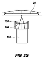
図2Cから2Kが、本開示の1つまたは複数の実施形態による結合機構の種々の実施形態を描いている。図2Cおよび2Dに示されるように、結合機構152が、宇宙船20のうちの少なくとも1つの宇宙船の受け部分(例えば、エンジン156)(例えば、エンジンの一部分、または機械的結合を行うことができる任意の他の部分)で受けられるように構成される拡大可能なドッキング機構160(例えば、スピア形状を有する)を備えることができる。拡大可能なドッキング機構160が、宇宙船作業用デバイス100(図2A)のみにより、またはロボットアームにより最終的なドッキングを誘導するという手法により、定位置まで誘導され、この間、宇宙船作業用デバイス100が宇宙船20に対しての位置を保持することになる。定位置にくると、1つまたは複数の拡大可能な部分が配備され得、受け部分156に接触することができ、それにより拡大可能なドッキング機構160を宇宙船20に固定する。
2C-2K depict various embodiments of the coupling mechanism according to one or more embodiments of the present disclosure. As shown in FIGS. 2C and 2D, the
このような拡大可能なドッキング機構160が、例えば、「SYSTEMS FOR CAPTURING A CLIENT VEHlCLE」と題される、2017年12月1日に出願された、米国特許出願第15,829,807号に開示されており、その開示の全体が本参照により本明細書に組み込まれる。例えば、拡大可能なドッキング機構160が図2Cに示されるように宇宙船20のエンジン156の中に挿入され得る。エンジン156の中に挿入されると、拡大可能なドッキング機構1560の1つまたは複数の部分が移動させられ得(例えば、拡大される、延伸される)、それによりエンジン156に接触し、拡大可能なドッキング機構160がエンジン156に固定され、それによりポッド102(図1)を宇宙船20に固定する。固定の前に、固定中に、および/または固定の後で、拡大可能なドッキング機構160が、ポッド102を宇宙船20により接近させるように配置するために後退させられる延伸アームを有することができる。
Such an
図2Eおよび2Fに示されるように、結合機構152が、宇宙船20の受け部分156に係合されるように構成される拡大可能なおよび/または後退可能なドッキング機構162(例えば、チャックの形状を有する)を備えることができる。ドッキング機構162が、上述の手法と同様の手法で定位置まで誘導され得る。定位置にくると、ドッキング機構162が後退または拡大することができ、それにより拡大可能なドッキング機構162が宇宙船20に固定される。
As shown in FIGS. 2E and 2F, the expandable and / or retractable docking mechanism 162 (eg, chuck shape) is configured such that the
図2Gおよび2Hに示されるように、結合機構152がスネア式の(snare)ドッキング機構164(例えば、空洞の開口部のところに配置される、例としては網状の金属ワイヤなどの、複数のワイヤを有する)を備えることができる。ドッキング機構162が、上述の手法と同様の手法で定位置まで誘導され得る。スネア式のドッキング機構164が、受け部分156をワイヤ内の開口部の中に入れるのを可能にすることにより、宇宙船20の受け部分156に係合されるように構成される。定位置にくると、スネア式のドッキング機構164が、ワイヤによって画定される開口部をワイヤにより少なくとも部分的に制限することになるように、移動し(例えば、回転する)、それによりスネア式のドッキング機構164が宇宙船20に固定される。
As shown in FIGS. 2G and 2H, the
図2Iおよび2Jに示されるように、結合機構152が、宇宙船20の受け部分156に係合されるように構成されるクランプ式のドッキング機構166(例えば、可動部材および2つの固定部材を有する3点クランプ機構)を備えることができる。ドッキング機構166が、上述した手法と同様の手法で定位置まで誘導され得る。定位置にくると、ドッキング機構166の可動部材が固定部材の方に移動することができ、それにより拡大可能なドッキング機構166を宇宙船20に固定する。
As shown in FIGS. 2I and 2J, the
図2Kに示されるように、結合機構152が、宇宙船20の受け部分156に係合されるように構成される膨張可能なクランプ式のドッキング機構168(例えば、受け部分156の外側部分および/または内側部分上で受けられるように構成される1つまたは複数の膨張可能なバッグ)を備えることができる。ドッキング機構168が、上述の手法と同様の手法で定位置まで誘導され得る。定位置にくると、膨張可能なバッグ(例えば、環状バッグ)または複数の膨張可能なバッグ(例えば、2つの対向するバッグ)が膨張することができ、それにより拡大可能なドッキング機構168が宇宙船20に固定される。いくつかの実施形態では、バッグに流体(例えば、液体)が充填されていてよく、この流体が構造間に少なくとも部分的である強固な接続を形成するように少なくとも部分的に固体化する。
As shown in FIG. 2K, the
図2Lが、上述のデバイスと同様であってよい宇宙船作業用デバイス180の斜視図である。描かれるように、宇宙船作業用デバイス180がESPAリングを備えるボディ182を有し、ここではポッド102がボディ182の周りに結合される。各ポッド102が、ターゲット宇宙船20(図1A)および任意選択のソーラーアレイ186に結合されるための結合機構184を有することができる。上記と同様に、結合機構184が、ターゲット宇宙船20のエンジンに係合されるように構成されるスピア形状の延伸可能なデバイスを備えることができる。
FIG. 2L is a perspective view of the
図1Aを参照すると、追加の実施形態において、ポッド102の構造部分(例えば、支柱または他のフレーム部材)が、宇宙船20にドッキングするのに利用され得る。例えば、ロボットアームまたは他の構造部(例えば、非ロボット式の方法)が、最初に、宇宙船20の幾何形状および構造部ならびに宇宙船20の構成要素(例えば、分離リング)の幾何形状および構造物に応じて所定のロケーションのところにポッド102を配置する。次いで、宇宙船作業用デバイス100が、ポッド102の構造部分を使用して宇宙船20にドッキングするができる。ドッキングが完了すると、ポッド102の構造部分が宇宙船20に固定され得る(例えば、クランプを作動させることによるか、あるいはロボットインターフェースを通した電子コマンドを介するかまたはロボットインターフェースからの電気機械的な駆動力を介して他の形で結合を強化することによる)。次いで、宇宙船作業用デバイス100の一部分(例えば、ロボットアーム)がポッド102を解放することができ、宇宙船作業用デバイス100が宇宙船20から切り離され得、ポッド102を宇宙船20に装着したままにしておく(例えば、分離リング上)。
With reference to FIG. 1A, in an additional embodiment, a structural portion of the pod 102 (eg, a strut or other frame member) can be utilized to dock with the
追加の実施形態では、宇宙船作業用デバイス100の一部分(例えば、ロボットアーム)がポッド102のところまで延伸してポッド102を宇宙船の一部分(例えば、宇宙船20の分離リングまたは他の適合する機械的構造部)の上に配置する。次いで、いずれかのデバイス上の結合機構または電子機械駆動装置を作動させるための、ポッド102または宇宙船20への電子コマンドが、ポッド102を宇宙船20上の定位置に固定するのに使用され得る。
In additional embodiments, a portion of the spacecraft working device 100 (eg, a robot arm) extends to the
図2Aを参照すると、ポッド102を配置するのにロボットアームが使用されるような例において、ロボットアーム112、エンドエフェクタ、および/または他のツールが、2つのビークルの間の無重力の接触力学を最小にするような、ドッキング機構166に関連するテクニックを採用することができる。このようなテクニックには、限定しないが、接触インターフェースのところの摩擦を最小にすること、最初の接触と強化との間の時間(例えば、ドッキングまたは他の形での結合を完了するための時間)を最小にすること、経路にある程度の余裕を与えることが含まれる。いくつかの実施形態では、受動的および能動的な最初の接触による静電気放電(ESD:electrostatic discharge)の軽減テクニックが、ポッド102、ロボットアーム112、宇宙船作業用デバイス100、および再供給デバイス30の設計において、最初の接触によるESDを最小にするかまたは排除するのに、採用され得る。このようなESD軽減が、例えば、「ELECTROSTATIC DISCHARGE MITIGATION FOR A FIRST SPACECRAFT OPERATING IN PROXIMITY TO A SECOND SPACECRAFT」と題される、2017年12月1日に出願された、米国特許出願第15/829,758号に開示されており、その開示の全体が本参照により本明細書に組み込まれる。
Referring to FIG. 2A, in an example where a robot arm is used to place the
図1Aを参照すると、ポッド102を宇宙船20の上に装着するときに宇宙船作業用デバイス100と宇宙船20との間の接続部を可能な限り単純なものとすることが望ましい可能性がある。いくつかの実施形態では、ポッド102の装着中、宇宙船20および宇宙船作業用デバイス100が短い時間(例えば、数秒から数分)のみにおいて一体にフリードリフトしてよく、ここでは、この短い時間においてポッド102の装着が確立され、宇宙船作業用デバイス100がポッド102を解放して2つのビークルの間の機械的接続を切り離す。次いで、宇宙船作業用デバイス100の推進システムが再起動され得、宇宙船作業用デバイス100が安全なロケーションまで後退することができる。その後すぐに、宇宙船20の姿勢制御システムが再起動され得、その結果、ターゲット宇宙船20がそのポジショニングを再確保することができるようになる。
With reference to FIG. 1A, it may be desirable to make the connection between the
図1Aおよび2Aを参照すると、いくつかの実施形態では、装着後、ポッド102が、例えば:ポッド102内の送受信機への地上コマンド、ロボットアーム112からの電子コマンド、を介して、起動され得、ここでは例えば、宇宙船作業用デバイス100、再供給デバイス30、またはロボットアーム122のいずれにもポッド102が接続されていないことをポッド102が感知するのを可能にするためのタイマーやセンサ(例えば、断線タイマー(break-wire timer)または同様のセンサ)が用いられる。いくつかの実施形態では、このようなセンサが、ドッキングまたは装着のための機械的活動が完了することによって起動される1つまたは複数の機械的リミットスイッチを有することができる。
With reference to FIGS. 1A and 2A, in some embodiments, after mounting, the
追加の実施形態では、ポッド102が、宇宙船作業用デバイス100とポッド102との間のインターフェースに組み込まれる構造部を介して、起動され得る。例えば、宇宙船作業用デバイス100の配備デバイスの一部分(例えば、ロボットアーム122の上にある、ツール駆動機構またはエンドエフェクタ)が、付属物を起動することおよび/または初期状態において付属物をポッド102上に配備することを補助することができる。このようなテクニックは潜在的に、ポッド102の配備および始動を実施する(例えば、ポッド102に対して1回のみ作動する)ための宇宙船作業用デバイス100のロボットアーム122の機能(例えば、ロボットアーム122のエンドエフェクタ)を利用することにより、ポッド102の機構を単純化する。ロボットアーム122、ならびに/あるいはロボットアーム122の構成要素およびツールが、ポッド102の軌道内での組み立てを少なくとも部分的に遂行することができる。例えば、ポッド102に対して付属物を最終的に組み付けるのにロボットアーム122を使用することにより、発射のためのポッド102の構成要素を、単純化すること、軽量化すること、および/またはそのパッケージングを低コスト化することを可能にすることができる。
In an additional embodiment, the
図3が、宇宙船作業用デバイス100のポッド(例えば、図1Aのミッション延長用ポッド102)の実施形態の簡略化された概略図を描いている。図3に示されるように、ミッション延長用ポッド102が、ポッド102を、およびポッド102のメインボディ201に取り付けられる任意の他の構造を制御する(例えば、方向付けて移動させる)ための1つまたは複数のデバイスを有する。例えば、ポッド102が化学的なまたは他の種類の反動エンジンを有することができ、ならびに/あるいは電気的に動力供給される推進システムを有することができる。描かれるように、1つまたは複数のスラスタ組立体200が、可動(例えば、回転可能な)結合装置(例えば、ジンバル204およびブーム206)を用いてポッド102に取り付けられる(例えば、移動可能に取り付けられる)1つまたは複数のスラスタ202(例えば、電気推進(EP:electric propulsion)スラスタ)を有することができる。いくつかの実施形態では、メインボディ201を基準としたスラスタ202のポジショニングが、ポッドを取り付けるところの宇宙船の1つまたは複数の特性(例えば、サイズ、寸法、質量、質量中心、これらの組み合わせ、など)に基づいて、選択され得る。いくつかの実施形態では、スラスタ202が、推進燃料タンク内を動き回る推進燃料を原因とする外乱を最小にするかまたは排除するために、比較的低い加速度を実現することができる。
FIG. 3 depicts a simplified schematic of an embodiment of a
図3の実施形態は単一のブーム206の上にある1つのスラスタ組立体200を示しているが、他の実施形態では、ポッド102が複数のブームの上にある複数のスラスタ組立体を有してもよい(例えば、2つ、3つ、またはそれより多いスラスタ組立体、および付随のブーム)。例えば、2つのスラスタ組立体が2つのブームの上に設けられ得、ここでは、一方のスラスタ組立体がもう一方のスラスタ組立体に対して実質的に鏡像をなす。さらに、いくつかの実施形態では、複数のスラスタ組立体が単一のブームの上に設けられてもよい。このような実施形態では、複数のスラスタが、十分なシステムのライフタイムスループット能力を実現するのをおよび所望の推進レベルに達するのを保証するように、実装され得る。いくつかの実施形態では、1つまたは複数のスラスタ組立体200がブームの上に設けられなくてよく、ポッド102の上に直接に装着され得る。いくつかの実施形態では、1つのスラスタ組立体200が、宇宙船の再配置、静止位置の保持、傾斜角引き下げ、運動量の調整、および/または寿命末期(EOL:end of life)での廃棄を含めた、寿命延長のための作業のために使用され得る。いくつかの実施形態では、複数のスラスタ組立体200の各々が寿命延長のためのすべての作業のために使用され得るか、または寿命延長のための異なる作業のために分けられ得る。例えば、1つまたは複数のスラスタ組立体200が静止位置の保持の作業のために1つまたは複数のブームの上に設けられ得、対して1つまたは複数のスラスタ組立体200が、軌道再配置、傾斜角引き下げ、およびEOLでの廃棄のためにポッド上に装着され得る。
The embodiment of FIG. 3 shows one
いくつかの実施形態では、アンテナ208がスラスタ組立体200の上に配置され得る。いくつかの実施形態では、アンテナ208が別個の配備可能なブームの上に配置され得る。いくつかの実施形態では、動力を発生させるための追加の太陽電池がスラスタブーム組立体200の上に配置され得る。
In some embodiments, the
ポッド102が、1つまたは複数の動力源と、付随の部品とを有する動力・推進システム210を有することができる(例えば、動力システムの少なくとも一部分が電気推進の動力システムであってよい場合)。例えば、動力・推進システム210が、1つまたは複数の推進燃料タンク(例えば、キセノン推進燃料、または電気的または化学的な推進システムのための任意適切な他の推進燃料を収容する)と、スラスタ(例えば、電子スラスタ)と、付随の電力処理ユニットとを有することができる。ポッド102が、ソーラーアレイ212と、1つまたは複数のバッテリ214とを有することができる。いくつかの実施形態では、ソーラーアレイ212がメインボディ201に強固に結合され得るか、またはソーラーアレイ212を太陽の方に向けるための1つまたは複数の運動軸を備える可動(例えば、回転可能な)結合装置に取り付けられ得る(例えば、1つ、2つ、またはそれ以上の軸を中心とする移動を実現するような、1つまたは複数のジンバル216または他の可動ジョイント、およびブーム218)。
The
いくつかの実施形態では、ジンバルを有するソーラーアレイ212が、同様の柔軟性を有さないアレイと比較して多くの利点を有することができる。例えば、ジンバルを有するソーラーアレイ212は、ソーラーアレイ212をターゲット宇宙船20のスラスタから取り外す/離間させるのを可能にし、その結果、ターゲット宇宙船20が、ポッド102のソーラーアレイのところまでターゲット宇宙船20のスラスタが入り込む懸念を最小にしながら軌道維持を遂行することができる。ジンバルを有するソーラーアレイ212はさらに、ターゲット宇宙船20からポッド102を熱的に切り離すことができ、太陽を追跡するのを可能にすることによりソーラーアレイ212の効果を向上させることができる。ジンバルを有するソーラーアレイ212の効果が向上することにより、ポッド102のスラスタをより長時間作動させることが可能となり、また、より小型で、より軽量で、より安価なバッテリを使用することも可能となる。より長時間作動する推進システムにより、重いターゲット宇宙船20に対して作業を行うことが容易となり得る。いくつかの実施形態では、ジンバルを有するソーラーアレイ212が、運動量を節約するような形で(例えば、正味、運動量が分与されないような形で)軌道上にあるターゲット20に関節接続され得る。
In some embodiments, the
いくつかの実施形態では、ソーラーアレイ212が、ソーラーアレイ212の動力発生を最大にしてそれによりソーラーアレイ212およびバッテリのサイズを最小にすることを目的として、人工衛星の太陽に照らされる部分が作業を行う間において、ポッド102に記憶されている論理を利用して太陽を追跡することができる。いくつかの実施形態では、例えば、機械的デザインを単純化することを目的として、ならびに宇宙船アレイが影で覆われるのを、スラスタプルームがポッド102および/または宇宙船20に衝突するのを、センサまたはアンテナがポッド102および/または宇宙船20に干渉するのを、または他のシステムの制約が発生するのを、排除するかまたは最小にすることを目的として、ソーラーアレイ212の移動が制限されてよい。いくつかの実施形態では、ソーラーアレイ212が、1つまたは2つの運動軸を有する2つの別個の翼を有することができる。いくつかの実施形態では、ジンバルを有するソーラーアレイ212が、ポッド102の回転に抵抗するように構成される1つの移動軸を有することができる。
In some embodiments, the
ポッド102の実施形態が、格子付きイオンスラスタ、Hall効果スラスタ、コロイドスラスタ/場効果スラスタ(field effect thruster)、アークジェット、およびレジストジェットなどの、低動力の(例えば、電気)推進システムを使用することにより、比較的物理的に小さいパッケージおよび低フットプリントの形で、宇宙船ビークル20(図1A)に対して、宇宙船のための作業を提供することができる。このような電気推進システムは、宇宙船20のポジショニングを調整するための1回または複数回の噴射のために、選択される時間にわたって必要となる量の推進を引き起こすことができる(例えば、24時間で2回の噴射)、ここでは、各々の推進が選択される時間だけ継続する。いくつかの実施形態では、ポッド102が、宇宙船およびポッド102のソーラーアレイ212の天頂の方を向く側(例えば、地球の反対側)に配置され得、それにより一日のうち少なくとも12時間にわたって邪魔されることなく日光を受けることができる。いくつかの実施形態では、ポッド102のソーラーアレイ212が完全に照らされている間において1回のスラスタ噴射が行われ得、対してポッド102のソーラーアレイ212が宇宙船ボディによって完全に覆い隠される間において2回目のスラスタ噴射が行われる。
Embodiments of
いくつかの実施形態では、24時間の間における各々のスラスタ噴射が、宇宙船20のボディによりポッド102のソーラーアレイ212が覆い隠される時間のうちの一部分を有してもよい。いくつかの実施形態では、24時間の間における各スラスタ噴射が、ポッド102のソーラーアレイ202が完全に照らされている間において、行われてもよい。バッテリ(例えば、リチウム-イオンバッテリなどの、バッテリ214)が、ポッド102が太陽に照らされている時間において、エネルギーを保存するのに使用され得、バッテリ214が、日光のない時間におけるポッド102のバスパワードロー(bus power draw)さらにはスラスタ噴射の動力をサポートするようにサイズ決定され得る。いくつかの実施形態では、スラスタ噴射が化学的なスラスタを用いて実施される。
In some embodiments, each thruster injection during the 24 hours may have a portion of the time that the body of the
いくつかの実施形態では、ポッド102の動力・推進システム210の推進燃料が、選択される期間(例えば、少なくとも複数年)にわたって宇宙船20(図1A)の静止位置の保持(例えば、必要とされる操縦および運動量の調整)をサポートするための量の推進燃料を有することができる(例えば、約25kg、50kg、100kg、150kg、またはそれ以上)。ポッド102が発射前に推進燃料を充填されていてよく、その結果、軌道内にくると推進燃料の移送が必要なくなる。宇宙船20が動作寿命の継続のために異なる軌道ロケーションへと再配置されるのを必要とするかまたはその動作寿命の終了に近づいている場合、動作寿命の延長または寿命末期での廃棄のために宇宙船20を、異なる軌道まで、異なる軌道位置まで、またはその組み合わせで、移動させることを目的として、ポッド102の推進のスケジュールおよび位置が、宇宙船20の軌道速度の方向において速度変化をもたらすように、調整され得る。
In some embodiments, the propellant fuel of the power and
いくつかの実施形態では、ポッド102の燃料または推進燃料が、宇宙船20の1つまたは複数のシステムに依存することなく、宇宙船20で作業を行うのに利用され得る。例えば、宇宙船20で作業を行うのに(例えば、操縦、および/または宇宙船20の姿勢を含めた少なくとも1つの運動量の調整)、ポッド102の推進燃料のみが利用され得る。
In some embodiments, the fuel or propellant fuel in the
図1Aおよび図3を参照すると、いくつかの実施形態では、宇宙船20で作業を行うのに、宇宙船20の燃料タンク24が迂回され得る(例えば、利用されない)。例えば、ポッド102の推進燃料(例えば、図1Bに示される構成と同様の構成においてタンク141から供給されるか、またはポッド102の推進システム210のタンクから供給される)が、(例えば、宇宙船20の燃料タンク24を迂回しながら)ターゲット宇宙船20の推進燃料システム22の一部分へと供給され得る(例えば、直接に供給され得る)。このような実施形態では、推進燃料を宇宙船20のタンク24へと移送(例えば、燃料補給)することなく(例えば、燃料補給手順を介する)、宇宙船20で作業を行うのにポッド102の推進燃料が利用され得る。例えば、ポッド102の推進燃料が、宇宙船20の燃料システムの一部分に連通され得る(例えば、結合機構152、対合するアダプタ145(図1B)、などを介して流体連通され得る)。いくつかの実施形態では、このような既存の接続部が宇宙船20上に存在してよい。いくつかの実施形態では、宇宙船作業用デバイス100およびポッド102のうちの一方または両方が、宇宙船20上の接続部の少なくとも一部分のところに装着され得る。
With reference to FIGS. 1A and 3, in some embodiments, the fuel tank 24 of the
ポッド102からの推進燃料がターゲット宇宙船20の推進燃料システム22の中まで移送され得、推進燃料システム22の1つまたは複数のスラスタを例えば使用して、宇宙船20で作業を行う(例えば、操縦、および/または宇宙船20の少なくとも1つの運動量の調整)のに利用され得る。
Propulsion fuel from the
いくつかの実施形態では、ポッド102が、ポッド102を独立して移動させるための推進デバイスを有さなくてよい。
いくつかの実施形態では、ポッド102が、例えば700キログラム(kg)未満といったように、比較的小さい総質量を有することができる(例えば、600kg未満、500kg未満、400kg未満、350kg未満、300kg未満、またはそれ以下)。
In some embodiments, the
In some embodiments, the
いくつかの実施形態では、ポッド102が、宇宙船20の上に永久的に留まり、回収または交換されないように、構成される。いくつかの実施形態では、ポッド102が宇宙船20から脱着され得、別のクライアント宇宙船上で使用され得る。いくつかの実施形態では、ポッド102が宇宙船20から脱着され得、宇宙船作業用デバイス100または再供給デバイス30によって燃料補給され得、宇宙船20に再び取り付けられ得る。
In some embodiments, the
ポッド102が、任意適切な種類のかつ任意適切な数の電子デバイス上に設けられるような、電力制御装置(例えば、単一の回路ボードの電力制御装置220)と、飛行制御装置(例えば、単一の回路ボードの航空電子工学制御装置222)とを有することができる。
A power controller (eg, a single circuit board power controller 220) and a flight controller (eg, a single circuit board) such that the
ポッド102が、アンテナ208および送受信機(XCVR)と通信するかまたは通信状態にある通信サブシステム224を有することができる(例えば、無線周波(RF))。ポッド102の通信サブシステム224が、継続的な接触を必要とするのではなく断続的な接触を用いる市販の通信サービスで動作するように設計され得る。
The
いくつかの実施形態では、ポッド102の通信デバイス(例えば、通信サブシステム224)が、ターゲット宇宙船20(図1A)の軌道または速度のうちの少なくとも一方に関連する(例えば、宇宙船20の運動量に関連する)データを受信することができる。このようなデータが、ポッド102から離れたところにあるロケーションからポッド102へと伝送され得るかまたは他の形で伝えられ得る(例えば、直接に、または地上局、衛星中継、直接的な伝送、および/またはターゲット宇宙船20などからの直接の電気接続を介して、間接的に、)。このようなデータが関連の噴射のための計算を含むことができ、および/またはポッド102のシステムがデータに基づいて噴射のための計算を実施することができる。いくつかの実施形態では、遠隔測定データが、直接に、または地上局を介して間接的に、ターゲット宇宙船20からポッド102へと提供され得る(例えば、無線周波リンクを介する)。いくつかの実施形態では、遠隔測定データが、ターゲット宇宙船20および宇宙船作業用デバイス100のうちの一方または両方から、または地上局から、直接にまたは間接的に、ポッド102へと提供され得る。
In some embodiments, the communication device of the pod 102 (eg, communication subsystem 224) is associated with at least one of the orbits or velocities of the target spacecraft 20 (eg, FIG. 1A) (eg, the momentum of the spacecraft 20). (Related to) data can be received. Such data can be transmitted to or otherwise transmitted from a location distant from the
ポッド102が一定期間(例えば、8時間から12時間)にわたって遠隔測定データを保存することができ、選択されるスケジュールに基づいてポーリングする(例えば、一日に2回または3回)ときにこのデータを通信ネットワークに戻すことができる。全体のデータセットは比較的少量であってよく、それにより接触時間を相対的に短縮することができ、それにより複数年の期間にわたって多数のポッド102を動作させることにおいて低コストのフットプリントを実現する。いくつかの実施形態では、ポッド102が、ターゲット宇宙船20(図1A)の地球ではない方を向く側に配置され得る。地上局のアンテナまでのおよび/または軌道を周回する通信サービスまでの見通し線を提供するために、送受信機のアンテナ208がスラスタ組立体200を担持する同一のブーム上に配置され得、それによりクリアな見通し線が得られる。比較的妥当であるようなゲインアンテナ208と併せて、地球同期軌道範囲と、本質的に低動力であるポッド102の構成要素とが与えられることにより、ポッド102が比較的低いデータ速度(例えば、1kb/秒未満、数kb/秒未満、など)でデータを転送および返信する。したがって、ポッド102が、地球からの宇宙船20のための宇宙船オペレータによって指定される調整に従うようにその推進スケジュールおよびブームのポインティングを調整するための限定のセットのコマンドを受信することができる。
This data can be stored when the
いくつかの実施形態では、システム10(図1A)の1つまたは複数の部分(例えば、ポッド102)が、フレキシブル周波数送受信機を利用することができ、このフレキシブル周波数送受信機が、宇宙船20に関連付けられる地上局とポッド20が通信するのを可能にすることができる。フレキシブル周波数送受信機を使用することによりおよび宇宙船20のための既存の地上システムを使用することにより、ポッド102が、ポッド102と宇宙船20のための地上局との間でのコマンド・遠隔測定の接続性を確立することにおいて、追加的な定期的な機関によるライセンス付与または第三者機関による作業を一切必要としなくてよい。これにより、定期的な開示またはライセンス付与をほぼ必要とすることなくまたは一切必要とすることなく、相対的に追加の出資を最小限にして、宇宙船20のオペレータがポッド102に対しての制御(例えば、完全な制御)を確立することが可能となる。ターゲット宇宙船20のマーケットベース(market base)には、通信のためにCバンドまたはKuバンドのRF周波数を利用する宇宙船20が比較的多く含まれることを考慮すると、発射されるポッド102が、CバンドまたはKuバンドの送受信機を有するように構成されてよい。発射前の調整により、初期能力により発射されるかまたは再供給用宇宙船内で発射されるような、CバンドベースのまたはKuバンドベースの通信システムを備えるポッド102の比率を確立することができる。ターゲット宇宙船20がCバンド通信またはKuバンド通信を利用しない場合、ポッド102は、ターゲット宇宙船20の通信システムに実質的に適合するような種類の通信システムを実装するように構成され得るか、あるいはCバンドまたはKuバンドのポッド102が、異なる種類の通信システムを有するターゲット宇宙船20と共に利用されてもよい。いくつかの実施形態では、ポッド102が、選択される期間(例えば、8時間から12時間)にわたってその遠隔測定データを保存することができ、ポーリングする(例えば、一日に2回または3回)ときにこのデータを通信ネットワークに戻すことができる。
In some embodiments, one or more parts of system 10 (FIG. 1A) (eg, pod 102) may utilize a flexible frequency transceiver, which the flexible frequency transceiver will be on
いくつかの実施形態では、フレキシブル周波数送受信機の周波数が軌道内にあるターゲット宇宙船20に基づいて修正され得る(例えば、ターゲット宇宙船20によって利用される1つまたは複数の周波数帯のうちの未使用部分を利用することを目的とする)ことを理由として、フレキシブル周波数送受信機がポッド102を多様なターゲット宇宙船20に繋ぐのを可能にすることができる。
In some embodiments, the frequency of the flexible frequency transmitter / receiver may be modified based on the
いくつかの実施形態では、ポッド102と宇宙船作業用デバイス100との間の宇宙間コマンドおよび遠隔測定リンクが、ポッド102を宇宙船20の地上システムに繋げるために宇宙船作業用デバイス100の比較的高いゲインおよび動力を利用するように実装され得る。いくつかの実施形態では、このテクニックが、ポッド102に対して宇宙船作業用デバイス100が非常に近接しているときに採用され得、および/またはポッド102のスラスタ噴射のスケジュールのために臨時の調整が必要となる可能性がある場合にのみ長期間のオペレーションのために宇宙船作業用デバイス100が据え付けられ得るときに、採用され得る(例えば、調整は毎週実施されるか、毎月実施されるか、より長いインターバルで実施される)。
In some embodiments, an interspace command and telemetry link between the
いくつかの実施形態では、ポッド102の通信システムが、宇宙船20のアップリンクアンテナに対してポッド102のアンテナを近接させることを利用するように設計される送受信機を使用することができ、それによりスペクトル拡散遠隔測定信号をポッド102から宇宙船20のアップリンク内へと送る。次いで、この信号が宇宙船20の通信システムによる高いゲインブーストを受け取り、それにより遠隔測定データをポッド102から地上へと送信する。
In some embodiments, the communication system of the
本明細書で開示されるポッド102内の種々の通信システムが、ポッド102の機能およびポッド102によって達成される成果をほぼ実時間で監視するのを可能にすることができ、ここでは地球同期軌道から地上までの光の速度のみがタイムラグの原因となる。このような構成は、ポッド102が複数の機能(例えば、上述した機能など)を遂行するのを可能にすることができ、ここではこれらの機能が性能データを地上局に返信することができる。さらに、地上局内のさらにはターゲット宇宙船20またはポッド102内のソフトウェアが、光の速度のタイムラグで「ループを閉じる」のに利用され得、その結果、ターゲット宇宙船20を制御するために、ポッド102またはターゲット宇宙船20からのデータがターゲット宇宙船20またはポッド102に付随のソフトウェアの中へ送達され得るようになる。いくつかの実施形態では、ポッド102がポッド102のホストである宇宙船20と直接に通信する必要がなくてよく、地上局を介して光の速度の往復のタイムラグで宇宙船20と通信してよい。このような実施形態では、宇宙船に対してポッド102が作業を行う形態で実現され得るような複雑な機能の場合に「ループを閉じる」ことが可能である。例えば、この複雑な機能には、宇宙船20からの遠隔測定データを使用する地上のソフトウェアまたはポッドのソフトウェアの中にあるジンバル制御論理により、ポッド102のスラスタ組立体200を用いて宇宙船20の3軸運動量を管理する能力が含まれてよい。
The various communication systems within the
ポッド102を別の宇宙船20(図1A)の上に配備して取り付けるために、ポッド102が、宇宙船20に取り付けられるように構成される取り付け構造部(例えば、ターゲット宇宙船20にドッキングすること、ターゲット宇宙船20に係留されること、ターゲット宇宙船20に取り付けられること、ターゲット宇宙船20を保持すること、またはこれらの組み合わせ、のうちの1つまたは複数を行うように構成される結合機構226)、ならびに/あるいは宇宙船作業用デバイス100(図2A)の構造部(例えば、ロボットアーム122)によって係合され得る1つまたは複数の結合構造部(例えば、握持機構228)を有することができる。結合機構226がメインボディ201に移動可能に設置され得る(例えば、ジンバル230を用いる)。
To deploy and mount the
いくつかの実施形態では、ポッド102のスラスタ組立体200が多軸アクチュエータシステム(例えば、複数のジンバルならびに/あるいは平行移動デバイスまたは回転デバイスによって画定される)上に配置され得る。例えば、ジンバル204が第1の軸方向にスラスタ組立体200を移動させるように構成され得、ジンバル205が、第1の軸方向に対して横向きである第2の軸方向にスラスタ組立体200を移動させるように構成され得る。いくつかの実施形態では、ジンバル204、205がスラスタ組立体200のところに配列され得る。いくつかの実施形態では、ジンバル204、205がブームによって分離され得る。ポッド102が、宇宙船ボディに対してジンバル204、205を位置決めするための第3のジンバル230を有することができる(例えば、宇宙船20(図1A)を基準としてメインボディ201を回転させる)。いくつかの実施形態では、ポッド102が、ジンバル204の近くにある第3のジンバル230を有することができる(例えば、メインボディ201とブーム206との間)。このような第3のジンバル230が、3自由度(例えば、3回転自由度)を得るようにジンバル204、205と協働して機能することができる。
In some embodiments, the
いくつかの実施形態では、握持機構228が、宇宙船作業用デバイス100(図2A)のロボットアーム122に結合されるのを容易にするために1つまたは複数の構造232によりメインボディ201から離間され得る。
In some embodiments, the
ポッド102が、ポッド102を宇宙船作業用デバイス100(図2A)に固定するのに利用される機構を有することができる。例えば、ポッド102が、宇宙船作業用デバイス100の一部分に結合される収容機構234(例えば、構造232によりメインボディ201から離間され得る)を有することができる。他の実施形態では、上記の既存の構造部(例えば、結合機構226、および/または握持機構228)のうちの1つまたは複数の構造部、あるいは別の構造部が、ポッド102を宇宙船作業用デバイス100に固定するのに使用され得る。
The
上で考察したように、ポッド102が、例えば宇宙船20の制御システムから分離されている間において(例えば、繋がれていない)、宇宙船20(図1A)に対して軌道速度の変化をもたらす(例えば、静止位置の保持、再配置、EOLでの廃棄)ように構成され得る。言い換えると、ポッド102のみが、宇宙船20に取り付けられているが宇宙船20の制御システムに繋がれていない間において宇宙船20の経路(例えば、軌道)を変化させることができる。速度変化はスラスタ202(例えば、イオンスラスタ、Hall電流スラスタ、格子付きイオンスラスタ、Hall効果スラスタ、あるいは任意的なレベルの推進を引き起こす他の任意適切な種類の電気スラスタまたは化学的なスラスタ)によりもたらされ得る。
As discussed above, while the
いくつかの実施形態では、上で考察したように、ポッド102が少なくとも部分的に、宇宙船20(図1A)に(例えば、宇宙船20の外側に)結合される補助燃料タンク(例えば、高圧キセノン、ヒドラジン、ヘリウム、四酸化窒素(NTO)、低毒性の推進燃料、これらの組み合わせ、または任意適切な他の燃料のタンク)として機能することができる。例えば、ポッド102が、動力・推進システム210内にこのようなタンクのうちの1つまたは複数のタンクを有することができる。他の実施形態では、後で考察するように、ポッド102が、タンクを宇宙船20に取り付けてタンクを宇宙船に連通させるように構成される付随の部品を備える燃料タンクのみを備えることができる。
In some embodiments, as discussed above, an auxiliary fuel tank (eg, high pressure) in which the
いくつかの実施形態では、ポッド102が、実質的に、補助タンクシステムのみを備えることができ、上述の構成要素のうちの大分部を有さなくてよいか上述の構成要素を一切有さなくてよい。このような補助タンクシステムポッド102は、初期状態においてシステムを与圧するための作業用弁、設備のためのおよび宇宙船に対しての取り付けのための機械的サポート、握持用の付属物、ならびに/あるいは受動的熱制御装置を有することができる。いくつかの実施形態では、配備デバイス(例えば、ロボットアーム)が、補助タンクポッド102をその目的地に配置するのに使用され得、目的地はタンクのホストとなるようにまたはタンクのホストとならないように協働的に設計され得る。この移送タンクポッド102のためのターゲット宇宙船20がガスおよび流体の移送のための協働的に設計されるインターフェースを有することができるか、または宇宙船20がこのようなインターフェースを有さない場合は、補助タンクポッド102が、この宇宙船20の上にある多様なサイズおよび構成の付属具に適合するように構成されるインターフェースを有することができる。
In some embodiments, the
図4が、第1の推進ベクトルの向き301を有する第1の構成300における、および第2の推進ベクトルの向き303を有する第2の構成302における、宇宙船20に取り付けられたポッド102の簡略化された概略図である。図3および4を参照すると、ジンバル204、205、230が、宇宙船20の質量中心を通るように推進力ベクトルを方向付けるための選択される数の自由度(例えば、2自由度、3自由度)を提供することができる。推進が、軌道内にある宇宙船20の初期位置に基づいて、コマンドにより(例えば、離れた地上局からの)および/またはスケジュールにより(例えば、所定のスケジュール、および/またはポッド102に能動的に伝送されるスケジュール)引き起こされ得、静止位置の保持における、および宇宙船20のサブシステムから運動量を取り除くことにおける、負荷を低減するかまたはさらには排除することができる。いくつかの実施形態では、推進力の大きさおよび/または推進力ベクトルが、ポッド102までの通信リンクを介して、任意の所望のスケジュールで、ポッド102に伝送され得る。
FIG. 4 shows a simplification of the
第1の推進ベクトルの向き301を実現するジンバル204、205、230の第1の構成300(例えば、3回転自由度)で示されるように、推進力が主として南の方向に加えられ得、つまり宇宙船軌道方向に対して非垂直である方向に加えられ得る。同様に、第2の推進ベクトルの向き303を実現するジンバル204、205、230の第2の構成032で示されるように、推進力が主として北の方向に加えられ得るか、または宇宙船軌道方向に対して垂直な方向に加えられ得る。図4に示されるように、各構成が、軌道速度の正方向および負方向において推進ベクトルの成分を有することができる。図5に示されるように、各構成(例えば、南向きの構成、および北向きの構成)における推進ベクトルがさらに、宇宙船の軌道の径方向において有意な大きさの成分を有することができる。コマンドによる(例えば、離れた地上局から)ならびに/あるいはスケジュール(例えば、所定のスケジュール、および/またはポッド102に能動的に伝送されるスケジュール)によるスラスタベクトルおよび噴射持続時間のわずかな変化が、後で考察するように、宇宙船20の静止位置の保持さらには運動量の調整を実施するのに使用される。いくつかの実施形態では、軌道内にあるときに推進ベクトルが多様な時間において宇宙船の周りの多様なロケーションのところに適用され得、それにより宇宙船の軌道要素の制御および宇宙船の運動量の管理を最適化する。
Propulsion can be applied primarily in the south direction, i.e. It can be added in a direction that is non-perpendicular to the spacecraft orbital direction. Similarly, as shown in the second configuration 032 of the
ポッド102からのこの追加の推進が、例えば、90%以上で、また最大で100%で、宇宙船20からの推進燃料の消費速度を低減することができ、それにより宇宙船20のミッションライフを延ばすように機能する。
This additional propellant from
一般に1回の起動継続時間(すなわち、噴射)において宇宙船20の軌道要素のドリフトを完全に排除するようには推進力が提供され得ないことを考慮して、各々の1回のスラスタ起動継続時間において、ポッド102が宇宙船20に対して1つまたは複数の軌道方向(例えば、軌道の径方向、垂直方向、非垂直方向、面方向)において方向性を有するわずかな速度を誘発することができ、さらには複数の起動継続時間を組み合わせることを介して、宇宙船20のすべての軌道要素の制御を達成することができる。例えば、1回の軌道周回(例えば、一日における2つの12時間の継続期間)における選択されるインターバルのために、および1週間、2週間、3週間、1ヶ月、またはそれより長い継続期間における多様な軌道周回のために、ポッド102の推進スケジュールが計画され得る。このようなスケジュールは、スラスト噴射と、付随のジンバル角度とを組み合わせるのを実現することができ、それにより速度変化を引き起こし、速度変化が一部のまたはすべての軌道要素を制御し、さらには速度変化と共にまたは速度変化とは別個に宇宙船の運動量を調整する。
Each one thruster activation continuation, taking into account that no propulsion force can generally be provided to completely eliminate the drift of the orbital elements of the
図5が、第1の推進ベクトルの向き305を有する第1の構成304におけるおよび第2の推進ベクトルの向き307を有する第2の構成306における、宇宙船20に取り付けられたポッド102(例えば、図4の図から90度回転させられる)の別の簡略化された概略図を提供する。図3および5を参照すると、ジンバル204、205が、宇宙船20の質量中心158を通るように推進力ベクトル305、307を方向付けるための2自由度を提供することができる。描かれるように、一日における12時間のインターバルの2つ期間のために(または、ターゲット宇宙船20のために所望の結果を提供する任意のインターバルのために)、ポッド102の推進スケジュールが計画され得る。このようなスケジュールはスラスト噴射305、307を組み合わせることを実現することができ、それにより速度変化を引き起こし、速度変化が互いを打ち消すことができるかまたは宇宙船の軌道の偏心を制御するのに使用される。
FIG. 5 shows a
いくつかの実施形態では、推進のコマンドおよび/またはスケジュールが作られてポッド102に伝えられ得、それにより、少なくとも部分的に宇宙船20の特性に基づいて、宇宙船20の所望の軌道、位置、および/または速度を実現する。
In some embodiments, propulsion commands and / or schedules can be created and communicated to the
いくつかの実施形態では、ポッド102の結合部分310(例えば、上で考察した拡大可能なドッキング機構160などの、ドッキング機構を含む)が、可動(例えば、回転可能な)ジョイントを有することができる。例えば、回転可能な結合部分310が、ターゲット宇宙船20を基準としてポッド102を回転させるのを可能にしながらポッド102をターゲット宇宙船20に固定することができる(例えば、ターゲット宇宙船のエンジン314の一部分に溶接することにより)。このような構成により、スラスタブームアーム312の自由度を得ることが可能となる(例えば、第3のジンバル230(図3)などの別個の可動ジョイントの必要性を排除し、さらには2つ以上のスラスタジンバル組立体の必要性を排除する)。
In some embodiments, the
図6が、宇宙船作業用システムの再供給デバイス(例えば、宇宙船作業用システム10(図1A)の再供給デバイス30)の簡略化された概略図である。図6に示されるように、再供給デバイス30が、構造400(例えば、ESPAリング)に取り付けられるかまたは構造400内に収容される複数のポッド102を有することができる。いくつかの実施形態では、各ポッド102が、構造400に結合されるためのそれぞれの取り付け機構401を有することができる。構造400が複数の結合装置を有することができる。これらは、例えば、発射ビークルの観測機器のうちの1つの観測機器に接続されるためのまたは発射ビークル自体に接続されるための、第1の結合装置402および第2の結合装置404である。構造400が、再供給デバイス30を制御すること、再供給デバイス30を監視すること、再供給デバイス30に動力供給することなどを目的とする、1つまたは複数の宇宙船システムを備えるバス406を有することができる。構造400が、システム10(図1A)(例えば、宇宙船作業用デバイス100(図2A))の別の部分に結合されるように構成される握持構造部408を有することができる。例えば、握持構造部408が、宇宙船作業用デバイス100のロボットアーム122を結合することができるところの構造を備えることができる(図2A)。いくつかの実施形態では、再供給デバイスの30の構造が、分離リングおよび/または宇宙船エンジンの類似の構造部(例えば、同様の形状および/または構成を有する構造)を有することができ、その結果、宇宙船作業用デバイス100をそれらにドッキングすることができるようになる。
FIG. 6 is a simplified schematic view of the resupply device of the spacecraft work system (eg, the
図7から図10が、本開示の1つまたは複数の実施形態による、宇宙船作業用デバイスに結合される複数のポッドを有する宇宙船作業用デバイスの種々の実施形態を描いている。図7に示されるように、宇宙船作業用デバイス500が、1つまたは複数の環状構造502(例えば、軸方向において互いの上に積み重ねられる2つのESPAリング)によって画定され得る。ポッド102が環状構造502の周りに結合され得る(例えば、少なくとも2つのポッド102のスタックとして)。例えば、ポッド102が、環状構造502の周りに画定される各ポートに結合され得る。ツール(例えば、ロボットアーム506)が環状構造502のうちの1つの環状構想に結合され得る(例えば、環状構造502の一方側の、径方向に延在する表面に結合され得る)。
7 to 10 illustrate various embodiments of a spacecraft working device with a plurality of pods coupled to the spacecraft working device according to one or more embodiments of the present disclosure. As shown in FIG. 7, the
図8に示されるように、宇宙船作業用デバイス500が、環状構造502の周りに結合される異なる構成のポッド102を有することができる。例えば、ポッド102が、環状構造502の周りに画定される各ポートに結合され得る。第2の列のポッド102が、環状構造502の隣に配置される(例えば、環状構造に隣接するおよび/または結合される)それぞれのポッド102に結合され得る。別のセットのポッド102が、環状構造502から延在する2つのポッド102のセットの間に配置され得る(例えば、結合され得る)。いくつかの実施形態では、選択される大きさのクリアランスがポッド102の間に設けられ得る(例えば、クリアランスが存在しないことも含まれる)。いくつかの実施形態では、最も外側のポッド102が、発射ビークル(例えば、観測機器のフェアリング)の一部分の直径の範囲内に配置されるか、この直径まで延在するか、またはこの直径を越えて延在するように、構成され得る。
As shown in FIG. 8, the
図9に示されるように、宇宙船作業用デバイス500が、環状構造502の周りに結合される異なる構成のポッド102を有することができる。例えば、ポッド102が、環状構造502の周りに画定される各ポートに結合され得るが、各ポートから離間される。第2の列のポッド102が、環状構造502の隣に配置されるそれぞれのポッド102に隣接するように(例えば、結合されるように)配置され得る。別のセットのポッド102が、環状構造502から延在する2つのポッド102のセットの間に配置され得る(例えば、結合され得る)。
As shown in FIG. 9, the
図10に示されるように、宇宙船作業用デバイス500が、環状構造502の周りに結合される異なる構成のポッド102を有することができる。例えば、選択される量のポッド102(例えば、3つのポッド102)が、環状構造502の周りに画定される各ポートに結合され得る。第2の列のポッド102が、環状構造502の隣に配置されるそれぞれのポッド102に隣接するように(例えば、結合されるように)配置され得る。別のセットのポッド102が、環状構造502の隣に配置されるそれぞれのポッド102のいずれかの側に配置され得る(例えば、結合され得る)。
As shown in FIG. 10, the
本開示の追加の非限定の実施形態には以下のものが含まれる:
実施形態1:宇宙船作業用システムであって、この宇宙船作業用システムが:宇宙船作業用デバイスと;少なくとも1つの宇宙船作業用構成要素を備える少なくとも1つのポッドであって、宇宙船作業用デバイスによって運ばれる、少なくとも1つのポッドとを備え、ここでは、宇宙船作業用デバイスが、少なくとも1つのポッドの少なくとも1つの宇宙船作業用構成要素を用いてターゲット宇宙船で作業することを目的として、宇宙船作業用システムの推進を利用して少なくとも1つのポッドをターゲット宇宙船まで移送するように構成され、宇宙船作業用デバイスが、ターゲット宇宙船に対して少なくとも1つのポッドが固定されるようになるまで少なくとも1つのポッドに少なくとも部分的に物理的に接触した状態を維持するように構成される。
Additional non-limiting embodiments of the present disclosure include:
Embodiment 1: A spacecraft working system, wherein the spacecraft working system is: a spacecraft working device; at least one pod with at least one spacecraft working component; With at least one pod carried by the device, the spacecraft working device is intended to work on the target spacecraft with at least one spacecraft working component of the at least one pod. At least one pod is configured to transfer to the target spacecraft using the propulsion of the spacecraft work system, and the spacecraft work device is secured with at least one pod to the target spacecraft. It is configured to maintain at least partial physical contact with at least one pod until it becomes available.
実施形態2:実施形態1の宇宙船作業用システムであって、宇宙船作業用デバイスが、宇宙船作業用システムの推進のみを利用して少なくとも1つのポッドをターゲット宇宙船まで移送するように構成される。 Embodiment 2: The spacecraft working system of Embodiment 1, configured such that the spacecraft working device transfers at least one pod to the target spacecraft using only the propulsion of the spacecraft working system. Will be done.
実施形態3:実施形態1または2の宇宙船作業用システムであって、少なくとも1つのポッドの少なくとも1つの宇宙船作業用構成要素が、ターゲット宇宙船の軌道または速度のうちの少なくとも1つを変化させるように構成されるスラスタ組立体を備える。
Embodiment 3: In the spacecraft working system of
実施形態4:実施形態1から3のいずれか1つの実施形態の宇宙船作業用システムであって、宇宙船作業用デバイスが、宇宙船作業用デバイスを6つの移動軸で移動させるように構成される推進システムを備える。 Embodiment 4: A spacecraft working system according to any one of embodiments 1 to 3, wherein the spacecraft working device is configured to move the spacecraft working device on six movement axes. Propulsion system is provided.
実施形態5:実施形態1から4のいずれか1つの実施形態の宇宙船作業用システムであって、宇宙船作業用デバイスが、ターゲット宇宙船の一部分の特性を検出するように構成される少なくとも1つのセンサを備える。 Embodiment 5: The spacecraft working system of any one of embodiments 1 to 4, wherein the spacecraft working device is configured to detect the characteristics of a portion of the target spacecraft. It has two sensors.
実施形態6:実施形態1から5のいずれか1つの実施形態の宇宙船作業用システムであって、少なくとも1つのセンサが、ターゲット宇宙船のドッキング構造に関連する特性を検出するように構成される。 Embodiment 6: The spacecraft working system of any one of embodiments 1-5, wherein at least one sensor is configured to detect properties related to the docking structure of the target spacecraft. ..
実施形態7:実施形態1から6のいずれか1つの実施形態の宇宙船作業用システムであって、少なくとも1つのセンサが、少なくとも1つのポッドの、配備、装着、または取り外しのうちの少なくとも1つを行うことを目的として、ターゲット宇宙船に対してのランデブーオペレーションまたは近接オペレーションのうちの少なくとも1つを容易にするように構成される。 Embodiment 7: A spacecraft working system according to any one of embodiments 1 to 6, wherein at least one sensor is at least one of deployment, mounting, or removal of at least one pod. It is configured to facilitate at least one of the rendezvous or proximity operations on the target spacecraft for the purpose of doing so.
実施形態8:実施形態1から7のいずれか1つの実施形態の宇宙船作業用システムであって、少なくとも1つのポッドが複数のポッドを含む。
実施形態9:実施形態1から8のいずれか1つの実施形態の宇宙船作業用システムであって、宇宙船作業用デバイスが、複数のポッドを保管して複数のポッドの各々を複数のターゲット宇宙船のうちの1つのターゲット宇宙船に配備するように構成される。
8: The spacecraft working system of any one of embodiments 1-7, wherein at least one pod comprises a plurality of pods.
Embodiment 9: A spacecraft working system according to any one of embodiments 1 to 8, wherein the spacecraft working device stores a plurality of pods and sets each of the plurality of pods into a plurality of target universes. It is configured to be deployed on one of the ships' target spacecraft.
実施形態10:実施形態1から9のいずれか1つの実施形態の宇宙船作業用システムであって、宇宙船作業用デバイスが、複数のポッドをターゲット宇宙船に配備するように構成される少なくとも1つの可動機構を備える。 Embodiment 10: A spacecraft working system of any one of embodiments 1-9, wherein the spacecraft working device is configured to deploy a plurality of pods on a target spacecraft. Equipped with two movable mechanisms.
実施形態11:実施形態1から10のいずれか1つの実施形態の宇宙船作業用システムであって、少なくとも1つの可動機構が、複数のポッドをターゲット宇宙船に配備するように構成されるロボットアームを備える。 11: A robotic arm of the spacecraft working system of any one of embodiments 1-10, wherein at least one movable mechanism is configured to deploy a plurality of pods on the target spacecraft. To be equipped with.
実施形態12:実施形態1から11のいずれか1つの実施形態の宇宙船作業用システムであって、宇宙船作業用デバイスが、ターゲット宇宙船からの少なくとも1つのポッドを回収するようにおよび/またはターゲット宇宙船からの少なくとも1つのポッドに燃料補給するように構成される。 Embodiment 12: The spacecraft working system of any one of embodiments 1-11, such that the spacecraft working device retrieves at least one pod from the target spacecraft and / or. It is configured to refuel at least one pod from the target spacecraft.
実施形態13:実施形態1から12のいずれか1つの実施形態の宇宙船作業用システムであって、この宇宙船作業用システムが、少なくとも1つの別のポッドを宇宙船作業用デバイスに供給するように構成される再供給デバイスをさらに備える。 13: A spacecraft working system of any one of embodiments 1-12, such that the spacecraft working system supplies at least one other pod to the spacecraft working device. Further equipped with a resupply device configured in.
実施形態14:実施形態1から13のいずれか1つの実施形態の宇宙船作業用システムであって、宇宙船作業用デバイスが、ターゲット宇宙船に隣接する位置に少なくとも1つのポッドを配置するように構成され、少なくとも1つのポッドが、少なくとも1つのポッドをターゲット宇宙船に固定することを目的としてターゲット宇宙船に隣接する位置においてターゲット宇宙船に係合されるように構成される結合機構を備える。 Embodiment 14: A spacecraft working system according to any one of embodiments 1 to 13, such that the spacecraft working device places at least one pod adjacent to the target spacecraft. It comprises a coupling mechanism configured such that at least one pod is configured to engage the target spacecraft at a position adjacent to the target spacecraft for the purpose of anchoring the at least one pod to the target spacecraft.
実施形態15:宇宙船作業用システムであって、この宇宙船作業用システムが:宇宙船作業用デバイスと;少なくとも1つの宇宙船作業用構成要素を備える少なくとも1つのポッドであって、少なくとも1つのポッドが宇宙船作業用デバイスによって運ばれる、少なくとも1つのポッドとを備え、ここでは、宇宙船作業用デバイスが、少なくとも1つのポッドの少なくとも1つの宇宙船作業用構成要素を用いてターゲット宇宙船で作業することを目的として、少なくとも1つのポッドをターゲット宇宙船まで移送するように構成される。 Embodiment 15: A spacecraft working system, wherein the spacecraft working system is: a spacecraft working device; at least one pod with at least one spacecraft working component, and at least one. The pod comprises at least one pod carried by the spacecraft working device, where the spacecraft working device is on the target spacecraft with at least one spacecraft working component of at least one pod. It is configured to transport at least one pod to the target spacecraft for the purpose of working.
実施形態16:実施形態15の宇宙船作業用システムであって、宇宙船作業用システムが、宇宙船作業用システムの推進のみを利用して少なくとも1つのポッドをターゲット宇宙船まで移送するように構成される。 Embodiment 16: The spacecraft working system of Embodiment 15, configured such that the spacecraft working system transfers at least one pod to the target spacecraft using only the propulsion of the spacecraft working system. Will be done.
実施形態17:実施形態15または16の宇宙船作業用システムであって、宇宙船作業用デバイスが、ターゲット宇宙船に隣接する位置に少なくとも1つのポッドを配置するように構成され、少なくとも1つのポッドが、少なくとも1つのポッドをターゲット宇宙船に固定することを目的として、ターゲット宇宙船に隣接する位置においてターゲット宇宙船に係合されるように構成される結合機構を備える。 Embodiment 17: A spacecraft working system of embodiment 15 or 16, wherein the spacecraft working device is configured to place at least one pod adjacent to the target spacecraft, at least one pod. Provides a coupling mechanism configured to engage the target spacecraft at a position adjacent to the target spacecraft for the purpose of fixing at least one pod to the target spacecraft.
実施形態18:実施形態15から17のいずれか1つの実施形態の宇宙船作業用システムであって、少なくとも1つの宇宙船作業用構成要素が、ターゲット宇宙船に対して、静止位置の保持、軌道上昇、運動量のバランシング、姿勢制御、再配置、軌道離脱、燃料補給、構成要素の交換、構成要素の追加、または修理、のうちの少なくとも1つを実施するように構成される。 Embodiment 18: The spacecraft working system of any one of embodiments 15 to 17, wherein at least one spacecraft working component maintains a stationary position and orbits with respect to the target spacecraft. It is configured to perform at least one of climbing, momentum balancing, attitude control, relocation, off-track, refueling, component replacement, component addition, or repair.
実施形態19:宇宙船作業用システムであって、この宇宙船作業用システムが:少なくとも1つのセンサを備える宇宙船作業用デバイスと;少なくとも1つの宇宙船作業用構成要素を備える少なくとも1つのポッドであって、宇宙船作業用デバイスによって運ばれる、少なくとも1つのポッドとを備え、ここでは、宇宙船作業用デバイスが、少なくとも1つのポッドの少なくとも1つの宇宙船作業用構成要素を用いてターゲット宇宙船で作業することを目的として少なくとも1つのポッドをターゲット宇宙船まで移送するように構成され、少なくとも1つのセンサが、少なくとも1つのポッドをターゲット宇宙船まで移送することに関連するターゲット宇宙船の一部分の特性を検出するように構成される。 Embodiment 19: A spacecraft work system, wherein the spacecraft work system: with a spacecraft work device with at least one sensor; with at least one pod with at least one spacecraft work component. There is at least one pod carried by the spacecraft working device, where the spacecraft working device is a target spacecraft with at least one spacecraft working component in at least one pod. At least one pod is configured to transfer to the target spacecraft for the purpose of working with, and at least one sensor is part of the target spacecraft associated with transferring at least one pod to the target spacecraft. It is configured to detect characteristics.
実施形態20:実施形態19の宇宙船作業用システムであって、少なくとも1つのセンサが、ターゲット宇宙船のドッキング構造に関連する特性を検出するように構成される。
実施形態21:実施形態19または20のいずれか1つの実施形態の宇宙船作業用システムであって、少なくとも1つのセンサが、少なくとも1つのポッドの、配備、装着、または取り外しのうちの少なくとも1つを行うことを目的として、ターゲット宇宙船に対してのランデブーオペレーションまたは近接オペレーションのうちの少なくとも1つを容易にするように構成される。
20: The spacecraft working system of embodiment 19, wherein at least one sensor is configured to detect properties related to the docking structure of the target spacecraft.
21: The spacecraft working system of any one of
実施形態22:実施形態19から21のいずれか1つの実施形態の宇宙船作業用システムであって、この宇宙船作業用システムが、宇宙船作業用デバイスを6つの移動軸で移動させるように構成される推進システムをさらに備える。 Embodiment 22: A spacecraft work system according to any one of embodiments 19 to 21, wherein the spacecraft work system is configured to move the spacecraft work device on six movement axes. Further equipped with a propulsion system to be carried out.
実施形態23:宇宙船作業用デバイスと、複数のポッドとを備える宇宙船作業用システムであって、宇宙船作業用デバイスが、複数のポッドの、装着、補給、燃料補給、脱着、再装着、または再使用、のうちの少なくとも2つを行うように構成される。 Embodiment 23: A spacecraft work system including a spacecraft work device and a plurality of pods, wherein the spacecraft work device includes mounting, replenishment, refueling, attachment / detachment, and reattachment of a plurality of pods. Or reuse, configured to do at least two.
実施形態24:宇宙船で作業する方法であって、この方法が:宇宙船に近接するところに宇宙船作業用デバイスを配置することと;宇宙船作業用デバイスに対して少なくとも1つのポッドが接触しているときに、少なくとも1つの宇宙船作業用構成要素を備える複数のポッドのうちの少なくとも1つのポッドを宇宙船まで移送することと、を含む。 Embodiment 24: A method of working on a spacecraft, the method of which is: placing the spacecraft working device in close proximity to the spacecraft; at least one pod is in contact with the spacecraft working device. Includes transporting at least one of a plurality of pods with at least one spacecraft working component to the spacecraft while doing so.
実施形態25:実施形態24の方法であって、この方法が、少なくとも1つのポッドの少なくとも1つの宇宙船作業用構成要素を用いて宇宙船で作業することをさらに含む。
実施形態26:実施形態24または25の方法であって、この方法が、宇宙船作業用デバイスが選択される量の複数のポッドを複数の宇宙船まで移送した後で再供給用宇宙船を用いて別の複数のポッドを宇宙船作業用デバイスに供給することをさらに含む。
25: A method of embodiment 24, further comprising working on a spacecraft with at least one spacecraft working component in at least one pod.
Embodiment 26: A method of embodiment 24 or 25, wherein the spacecraft working device uses a resupply spacecraft after transferring a selected amount of a plurality of pods to the spacecraft. Further includes supplying a plurality of other pods to the spacecraft working device.
上述の開示のおよび添付図面に示される実施形態は本開示の範囲を限定するものではない。というのは、これらの実施形態が、添付の特許請求の範囲およびそれらの法的均等物によって定義される本開示の実施形態の単に例であるからである。いかなる等価の実施形態も本開示の範囲内にあることを意図される。実際には、本記述により、本明細書で示されて説明されるものに加えて、説明される要素の代替的な有用な組み合わせなどの、本開示の種々の修正形態が当業者には明らかとなろう。このような修正形態および実施形態も、添付の特許請求の範囲およびそれらの法的均等物の範囲内にあることを意図される。
The embodiments shown in the above disclosure and the accompanying drawings do not limit the scope of the present disclosure. This is because these embodiments are merely examples of the embodiments of the present disclosure as defined by the appended claims and their legal equivalents. Any equivalent embodiment is intended to be within the scope of this disclosure. In practice, the description reveals to those skilled in the art various modifications of the disclosure, such as alternative useful combinations of the elements described, in addition to those shown and described herein. Let's be. Such modifications and embodiments are also intended to be within the scope of the appended claims and their legal equivalents.
Claims (22)
少なくとも1つの宇宙船作業用構成要素を備える少なくとも1つのポッドであって、前記宇宙船作業用デバイスによって運ばれる、少なくとも1つのポッドと
を備え、
前記宇宙船作業用デバイスが、前記少なくとも1つのポッドの前記少なくとも1つの宇宙船作業用構成要素を用いてターゲット宇宙船で作業することを目的として、前記ポッドの推進システム及び/又は前記宇宙船作業用デバイスの推進システムを用いて少なくとも1つのポッドをターゲット宇宙船まで移送して前記ターゲット宇宙船に1以上の寿命延長作業を提供するように構成され、
前記宇宙船作業用デバイスが、前記ターゲット宇宙船に対して前記少なくとも1つのポッドが固定されるようになるまで前記少なくとも1つのポッドに少なくとも部分的に物理的に接触した状態を維持するように構成され、
前記宇宙船作業用デバイスが、前記ターゲット宇宙船に対して前記少なくとも1つのポッドが固定された後で前記少なくとも1つのポッドとの物理的接触を解除するように構成され、
前記少なくとも1つのポッドの前記少なくとも1つの宇宙船作業用構成要素は、前記ターゲット宇宙船の軌道または速度のうちの少なくとも1つを変化させるように構成される、スラスタ組立体を備える、
宇宙船作業用システム。 Spacecraft work devices and
At least one pod with at least one spacecraft working component, with at least one pod carried by said spacecraft working device.
The pod propulsion system and / or the spacecraft operation for the purpose of the spacecraft operation device working on the target spacecraft using the at least one spacecraft operation component of the at least one pod. The device's propulsion system is configured to transport at least one pod to the target spacecraft to provide the target spacecraft with one or more life extension tasks.
The spacecraft working device is configured to maintain at least partial physical contact with the at least one pod until the at least one pod is anchored to the target spacecraft. Being done
The spacecraft working device is configured to release physical contact with the at least one pod after the at least one pod has been secured to the target spacecraft.
The at least one spacecraft working component of the at least one pod comprises a thruster assembly configured to alter at least one of the orbits or velocities of the target spacecraft.
Spacecraft work system.
少なくとも1つの光学的センサを備える宇宙船作業用デバイスと、
少なくとも1つの宇宙船作業用構成要素を備える少なくとも1つのポッドであって、宇宙船作業用デバイスによって運ばれる、少なくとも1つのポッドと
を備え、
前記宇宙船作業用デバイスが、前記少なくとも1つのポッドの前記少なくとも1つの宇宙船作業用構成要素を用いてターゲット宇宙船で作業することを目的として前記少なくとも1つのポッドをターゲット宇宙船の外側部分まで移送するように構成され、
前記少なくとも1つの光学的センサが、前記ターゲット宇宙船のドッキング機構に関する特性を検出するように構成され、
前記宇宙船作業用デバイスが、前記少なくとも1つの光学的センサにより検出された特性に基づいて、前記少なくとも1つのポッドと前記ターゲット宇宙船との間でのアタッチメントの方法を決定するようになっている、
宇宙船作業用システム。 It ’s a spacecraft work system,
A spacecraft work device with at least one optical sensor,
At least one pod with at least one spacecraft working component, with at least one pod carried by a spacecraft working device.
The spacecraft working device extends the at least one pod to the outer portion of the target spacecraft for the purpose of working on the target spacecraft using the at least one spacecraft working component of the at least one pod. Configured to transport
The at least one optical sensor is configured to detect properties relating to the docking mechanism of the target spacecraft.
The spacecraft working device is adapted to determine the method of attachment between the at least one pod and the target spacecraft based on the characteristics detected by the at least one optical sensor. ,
Spacecraft work system.
前記宇宙船に近接するところに宇宙船作業用デバイスを配置するステップと、
前記宇宙船作業用デバイスに対して少なくとも1つのポッドが物理的に接触しているときに、少なくとも1つの宇宙船作業用構成要素を備える複数のポッドのうちの少なくとも1つのポッドを前記宇宙船の外側部分まで移送するステップと、
前記宇宙船に接続され、前記宇宙船の外の、所定の位置に少なくとも1つのポッドを残しながら、前記宇宙船に対して前記少なくとも1つのポッドが固定された後で前記少なくとも1つのポッドとの物理的接触を解除するステップと、
前記少なくとも1つのポッドを有する前記宇宙船に1以上の寿命延長作業を提供するステップと、
を含む、
方法。 It ’s a way to work on a spaceship,
The step of arranging the spacecraft work device in the vicinity of the spacecraft ,
When at least one pod is in physical contact with the spacecraft working device, at least one of the plurality of pods having at least one spacecraft working component is of the spacecraft. Steps to transfer to the outer part and
With the at least one pod after the at least one pod has been fixed to the spacecraft while being connected to the spacecraft and leaving at least one pod in place outside the spacecraft. Steps to release physical contact and
The step of providing one or more life extension work to the spacecraft having the at least one pod, and
including,
Method.
宇宙船作業用デバイスと、
ターゲット宇宙船に対して1以上の寿命延長作業を提供するための少なくとも1つの宇宙船作業用構成要素を備える少なくとも1つのポッドであって、前記宇宙船作業用デバイスによって運ばれる、少なくとも1つのポッドと
を備え、
前記宇宙船作業用デバイスが、前記少なくとも1つのポッドの前記少なくとも1つの宇宙船作業用構成要素を用いて前記ターゲット宇宙船で作業することを目的として、前記少なくとも1つのポッドを前記ターゲット宇宙船まで移送するように構成され、
前記少なくとも1つのポッドが、前記少なくとも1つのポッドを前記ターゲット宇宙船に固定するための結合機構をさらに備え、
前記結合機構が、前記少なくとも1つのポッドが前記ターゲット宇宙船の外のロケーションのところに配置されたままでいるように、前記ターゲット宇宙船の外側部分に係合されるように構成される、
宇宙船作業用システム。 It ’s a spacecraft work system,
Spacecraft work devices and
At least one pod with at least one spacecraft working component for providing one or more life extension work to the target spacecraft, and at least one pod carried by the spacecraft working device. With and
The spacecraft working device moves the at least one pod to the target spacecraft for the purpose of working on the target spacecraft using the at least one spacecraft working component of the at least one pod. Configured to transport
The at least one pod further comprises a coupling mechanism for fixing the at least one pod to the target spacecraft.
The coupling mechanism is configured to engage the outer portion of the target spacecraft such that the at least one pod remains located at a location outside the target spacecraft.
Spacecraft work system.
請求項20に記載の宇宙船作業用システム It is configured to transport the at least one pod to the target spacecraft using only the propulsion system of the spacecraft working system.
The spacecraft working system according to claim 20.
前記宇宙船作業用デバイスが、前記複数のポッドのうちの少なくとも1つのポッドをターゲット宇宙船の推進機関の一部分に装着するように構成され、
前記宇宙船作業用デバイスが、
前記複数のポッドのうちの前記少なくとも1つのポッドを前記ターゲット宇宙船の前記推進機関の前記一部分から分離すること、
前記複数のポッドのうちの前記少なくとも1つのポッドを前記ターゲット宇宙船の前記推進機関の前記部分に再装着すること、
前記複数のポッドのうちの前記少なくとも1つのポッドを別のターゲット宇宙船の推進機関の一部分に再装着すること、
前記複数のポッドのうちの前記少なくとも1つのポッドに燃料を供給して再利用すること
のうちの少なくとも2つを行うようにさらに構成される、
宇宙船作業用システム。 A spacecraft work system with spacecraft work devices and multiple pods.
The spacecraft working device is configured to mount at least one of the plurality of pods on a portion of the target spacecraft's propulsion engine.
The spacecraft work device
Separating the at least one of the plurality of pods from the portion of the propulsion engine of the target spacecraft.
Remounting at least one of the plurality of pods to the portion of the propulsion engine of the target spacecraft.
Refitting the at least one of the plurality of pods to a portion of the propulsion engine of another target spacecraft.
Further configured to perform at least two of fueling and reusing the at least one of the plurality of pods.
Spacecraft work system.
Priority Applications (2)
| Application Number | Priority Date | Filing Date | Title |
|---|---|---|---|
| JP2022109631A JP7297988B2 (en) | 2017-07-21 | 2022-07-07 | Spacecraft working device and related assemblies, systems and methods |
| JP2023096988A JP7561237B2 (en) | 2017-07-21 | 2023-06-13 | Spacecraft working devices and related assemblies, systems, and methods - Patents.com |
Applications Claiming Priority (3)
| Application Number | Priority Date | Filing Date | Title |
|---|---|---|---|
| US201762535747P | 2017-07-21 | 2017-07-21 | |
| US62/535,747 | 2017-07-21 | ||
| PCT/US2018/043180 WO2019018819A1 (en) | 2017-07-21 | 2018-07-20 | Spacecraft servicing devices and related assemblies, systems, and methods |
Related Child Applications (1)
| Application Number | Title | Priority Date | Filing Date |
|---|---|---|---|
| JP2022109631A Division JP7297988B2 (en) | 2017-07-21 | 2022-07-07 | Spacecraft working device and related assemblies, systems and methods |
Publications (3)
| Publication Number | Publication Date |
|---|---|
| JP2020527504A JP2020527504A (en) | 2020-09-10 |
| JP2020527504A5 JP2020527504A5 (en) | 2021-07-26 |
| JP7104773B2 true JP7104773B2 (en) | 2022-07-21 |
Family
ID=63143396
Family Applications (9)
| Application Number | Title | Priority Date | Filing Date |
|---|---|---|---|
| JP2020502142A Active JP7104773B2 (en) | 2017-07-21 | 2018-07-20 | Spacecraft working devices and related assemblies, systems, and methods |
| JP2020502129A Active JP7092864B2 (en) | 2017-07-21 | 2018-07-20 | Spacecraft working devices, as well as related assemblies, systems, and methods. |
| JP2020502155A Active JP7144505B2 (en) | 2017-07-21 | 2018-07-20 | Spacecraft working device and related assemblies, systems and methods |
| JP2022096469A Active JP7297986B2 (en) | 2017-07-21 | 2022-06-15 | Spacecraft working device and related assemblies, systems and methods |
| JP2022109631A Active JP7297988B2 (en) | 2017-07-21 | 2022-07-07 | Spacecraft working device and related assemblies, systems and methods |
| JP2022145726A Active JP7326566B2 (en) | 2017-07-21 | 2022-09-14 | Spacecraft working device and related assemblies, systems and methods |
| JP2023096691A Active JP7561236B2 (en) | 2017-07-21 | 2023-06-13 | Spacecraft working devices and related assemblies, systems, and methods - Patents.com |
| JP2023096988A Active JP7561237B2 (en) | 2017-07-21 | 2023-06-13 | Spacecraft working devices and related assemblies, systems, and methods - Patents.com |
| JP2023125300A Active JP7561244B2 (en) | 2017-07-21 | 2023-08-01 | Spacecraft working devices and related assemblies, systems, and methods - Patents.com |
Family Applications After (8)
| Application Number | Title | Priority Date | Filing Date |
|---|---|---|---|
| JP2020502129A Active JP7092864B2 (en) | 2017-07-21 | 2018-07-20 | Spacecraft working devices, as well as related assemblies, systems, and methods. |
| JP2020502155A Active JP7144505B2 (en) | 2017-07-21 | 2018-07-20 | Spacecraft working device and related assemblies, systems and methods |
| JP2022096469A Active JP7297986B2 (en) | 2017-07-21 | 2022-06-15 | Spacecraft working device and related assemblies, systems and methods |
| JP2022109631A Active JP7297988B2 (en) | 2017-07-21 | 2022-07-07 | Spacecraft working device and related assemblies, systems and methods |
| JP2022145726A Active JP7326566B2 (en) | 2017-07-21 | 2022-09-14 | Spacecraft working device and related assemblies, systems and methods |
| JP2023096691A Active JP7561236B2 (en) | 2017-07-21 | 2023-06-13 | Spacecraft working devices and related assemblies, systems, and methods - Patents.com |
| JP2023096988A Active JP7561237B2 (en) | 2017-07-21 | 2023-06-13 | Spacecraft working devices and related assemblies, systems, and methods - Patents.com |
| JP2023125300A Active JP7561244B2 (en) | 2017-07-21 | 2023-08-01 | Spacecraft working devices and related assemblies, systems, and methods - Patents.com |
Country Status (10)
| Country | Link |
|---|---|
| US (9) | US10850869B2 (en) |
| EP (6) | EP4147981A1 (en) |
| JP (9) | JP7104773B2 (en) |
| CN (9) | CN117246529A (en) |
| AU (4) | AU2018304554B2 (en) |
| CA (3) | CA3070501A1 (en) |
| IL (7) | IL283640B2 (en) |
| RU (6) | RU2022100795A (en) |
| SG (3) | SG11202000591VA (en) |
| WO (3) | WO2019018819A1 (en) |
Families Citing this family (32)
| Publication number | Priority date | Publication date | Assignee | Title |
|---|---|---|---|---|
| WO2018180086A1 (en) * | 2017-03-31 | 2018-10-04 | 株式会社Ihiエアロスペース | Docking device |
| IL283640B2 (en) * | 2017-07-21 | 2024-08-01 | Northrop Grumman Innovation Systems Llc | Spacecraft servicing devices and related assemblies, systems, and methods |
| WO2019051432A1 (en) | 2017-09-10 | 2019-03-14 | Space Arena, Inc. | Enclosures for facilitating activities in space, and associated systems and methods |
| US11530053B2 (en) * | 2017-11-09 | 2022-12-20 | Skycorp, Inc. | Systems and methods for spacecraft reprovisioning |
| US11034235B2 (en) | 2017-12-06 | 2021-06-15 | Orbit Fab, Inc. | Systems and methods for creating and automating an enclosed volume with a flexible fuel tank and propellant metering for machine operations |
| US11016166B1 (en) * | 2018-09-27 | 2021-05-25 | United States Of America As Represented By The Administrator Of Nasa | Ultra-compact star scanner |
| AU2020208316A1 (en) | 2019-01-15 | 2021-08-05 | Northrop Grumman Systems Corporation | Spacecraft servicing devices and related assemblies, systems, and methods |
| US20200262589A1 (en) * | 2019-02-15 | 2020-08-20 | Space Systems/Loral, Llc | Attitude rate mitigation of spacecraft in close proximity |
| WO2020256792A1 (en) * | 2019-06-17 | 2020-12-24 | The Board Of Trustees Of The University Of Illinois | Multifunctional structures for attitude control |
| US11292618B2 (en) * | 2019-07-03 | 2022-04-05 | Mitsubishi Electric Research Laboratories, Inc. | Nonlinear model predictive control of coupled celestial system |
| US11492143B2 (en) * | 2019-08-08 | 2022-11-08 | Atomos Nuclear and Space Corporation | Multi-Orbital Transfer Vehicle constellation and method of use |
| US11643227B2 (en) * | 2019-09-24 | 2023-05-09 | Astroscale Israel, Ltd. | In-orbit spacecraft servicing through umbilical connectors |
| IL269920B2 (en) * | 2019-10-10 | 2024-10-01 | Israel Aerospace Ind Ltd | Projectile trajectory shaping |
| IT201900019322A1 (en) * | 2019-10-18 | 2021-04-18 | Thales Alenia Space Italia Spa Con Unico Socio | END-TO-END ASSISTANCE IN ORBIT |
| CN111252269B (en) * | 2020-01-21 | 2020-12-18 | 上海宇航系统工程研究所 | On-orbit transfer device |
| US12030674B2 (en) * | 2020-03-07 | 2024-07-09 | Voyager Space Ip Holdings, Llc | Fluid transfer interface |
| US11827386B2 (en) | 2020-05-04 | 2023-11-28 | Northrop Grumman Systems Corporation | Vehicle capture assemblies and related devices, systems, and methods |
| US20240059430A1 (en) * | 2020-11-05 | 2024-02-22 | Katalyst Space Technologies, Llc | Attachment systems for augmenting satellites |
| US11981457B1 (en) | 2020-12-14 | 2024-05-14 | Bae Systems Space & Mission Systems Inc. | Multipurpose spacecraft structure and propulsion system |
| WO2022153619A1 (en) * | 2021-01-15 | 2022-07-21 | Astroscale Holdings Inc. | Method and system for multi-object space debris removal |
| CN113001558B (en) * | 2021-02-23 | 2022-08-26 | 上海宇航系统工程研究所 | Modularized quick-change maintenance integrated platform suitable for space operation |
| CN113341775B (en) * | 2021-06-02 | 2022-04-12 | 天津云圣智能科技有限责任公司 | Pod dispatching method, device and system |
| CN113353295A (en) * | 2021-06-29 | 2021-09-07 | 杨德安 | Solid fuel space capsule |
| WO2023154153A1 (en) * | 2022-02-14 | 2023-08-17 | Maxar Space Llc | Satellite boom end effector |
| US20230257137A1 (en) * | 2022-02-14 | 2023-08-17 | Maxar Space Llc | Satellite boom end effector |
| EP4306433A1 (en) | 2022-07-12 | 2024-01-17 | ClearSpace SA | Spacecraft docking system and method |
| CN115352659B (en) * | 2022-08-22 | 2023-05-12 | 哈尔滨工业大学(深圳) | On-orbit construction system based on primary and secondary spacecraft |
| WO2024096876A1 (en) * | 2022-11-02 | 2024-05-10 | Green David L | Satellite rescue system and method |
| CN115817867B (en) * | 2022-12-30 | 2023-11-24 | 中国科学院空间应用工程与技术中心 | On-line maintenance operation box for space station effective load |
| US12097979B1 (en) | 2023-03-01 | 2024-09-24 | Astroscale Israel, Ltd. | Satellite for rendezvous and docking using electric propulsion thrusters |
| CN116513491B (en) * | 2023-07-05 | 2023-09-15 | 北京未来宇航空间科技研究院有限公司 | Superior and space replenishment system |
| CN116534279B (en) * | 2023-07-05 | 2023-09-08 | 北京未来宇航空间科技研究院有限公司 | Satellite orbit deployment device and assembly thereof |
Citations (1)
| Publication number | Priority date | Publication date | Assignee | Title |
|---|---|---|---|---|
| JP2016068730A (en) | 2014-09-30 | 2016-05-09 | 株式会社Ihi | Debris removal apparatus and debris removal method |
Family Cites Families (179)
| Publication number | Priority date | Publication date | Assignee | Title |
|---|---|---|---|---|
| US3268091A (en) * | 1961-06-01 | 1966-08-23 | Gen Mills Inc | Reaction thrust operated manipulator |
| US3508723A (en) | 1967-12-26 | 1970-04-28 | Nasa | Method and apparatus for securing to a spacecraft |
| US3662973A (en) | 1970-07-31 | 1972-05-16 | Nasa | Flight control system |
| US4219171A (en) | 1979-02-06 | 1980-08-26 | The United States Of America As Represented By The Administrator Of The National Aeronautics And Space Administration | Device for coupling a first vehicle to a second vehicle |
| US4449684A (en) | 1979-07-03 | 1984-05-22 | Spar Aerospace Limited | Satellite servicing |
| US4298178A (en) | 1980-01-10 | 1981-11-03 | General Dynamics | Roving geosynchronous orbit satellite maintenance system |
| US4391423A (en) | 1981-03-30 | 1983-07-05 | The United States Of America As Represented By The Administrator Of The National Aeronautics And Space Administration | Satellite retrieval system |
| US4381092A (en) | 1981-05-01 | 1983-04-26 | Martin Marietta Corporation | Magnetic docking probe for soft docking of space vehicles |
| US4431333A (en) | 1982-04-14 | 1984-02-14 | The United States Of America As Represented By The Administrator Of The National Aeronautics And Space Administration | Apparatus for releasably connecting first and second objects in predetermined space relationship |
| DE3215229A1 (en) | 1982-04-23 | 1983-10-27 | Erno Raumfahrttechnik Gmbh, 2800 Bremen | CONNECTING DEVICE FOR SPACING BODIES |
| US4657211A (en) | 1984-11-20 | 1987-04-14 | Rca Corporation | Spacecraft to shuttle docking method and apparatus |
| US4664344A (en) | 1985-11-07 | 1987-05-12 | The United States Of America As Represented By The Administrator Of The National Aeronautics And Space Administration | Apparatus and method of capturing an orbiting spacecraft |
| US4880187A (en) | 1986-01-16 | 1989-11-14 | Trw Inc. | Multipurpose modular spacecraft |
| EP0257040B1 (en) * | 1986-02-18 | 1990-09-12 | Hughes Aircraft Company | Low pressure reaction control propulsion system for a spacecraft |
| WO1987007877A1 (en) * | 1986-06-19 | 1987-12-30 | Hughes Aircraft Company | Hybrid spacecraft control system |
| US4750692A (en) | 1987-04-07 | 1988-06-14 | Howard Thomas R | Satellite retrieval apparatus |
| US4955559A (en) | 1988-01-26 | 1990-09-11 | Trw Inc. | Thrust vector control system for aerospace vehicles |
| JPH01282098A (en) | 1988-05-09 | 1989-11-13 | Ishikawajima Harima Heavy Ind Co Ltd | Disconnecting device for apparatus |
| US4898348A (en) | 1988-12-30 | 1990-02-06 | The United States Of America As Represented By The Administrator Of The National Aeronautics And Space Administration | Docking system for spacecraft |
| JP2676243B2 (en) | 1989-01-06 | 1997-11-12 | 宇宙開発事業団 | Docking mechanism |
| US5040749A (en) | 1989-02-22 | 1991-08-20 | Space Industries, Inc. | Spacecraft berthing mechanism with discrete impact attennation means |
| JP2564186B2 (en) | 1989-03-01 | 1996-12-18 | 科学技術庁航空宇宙技術研究所 | Space structure vibration control device |
| US5104070A (en) | 1989-06-01 | 1992-04-14 | Space Industries, Inc. | Structural latch for vehicle coupling mechanisms |
| US5094410A (en) | 1989-10-31 | 1992-03-10 | Space Industries, Inc. | Capture/berthing system for spacecraft |
| EP0445011B1 (en) | 1990-02-26 | 1993-11-10 | AEROSPATIALE Société Nationale Industrielle | Geostationary observation satellite with multi-nozzle liquid propellant apogee manoeuvering system |
| US5169094A (en) | 1990-02-26 | 1992-12-08 | Aerospatiale Societe Nationale Industrielle | Geostationary earth observation satellite incorporating liquid propellant apogee maneuver system and hollow antennas |
| US5145227A (en) | 1990-12-31 | 1992-09-08 | The United States Of America As Represented By The Administrator Of The National Aeronautics And Space Administration | Electromagnetic attachment mechanism |
| US5299764A (en) | 1991-10-23 | 1994-04-05 | Scott David R | In-space servicing of spacecraft employing artificial life robotics |
| DE69208204T2 (en) | 1991-11-05 | 1996-06-13 | Hitachi Ltd | Spacecraft system |
| US5125601A (en) | 1991-12-26 | 1992-06-30 | The United States Of America As Represented By The Administrator, National Aeronautics And Space Administration | Payload retention device |
| US5364046A (en) | 1992-02-24 | 1994-11-15 | Environmental Research Institute Of Michigan | Automatic compliant capture and docking mechanism for spacecraft |
| US5349532A (en) | 1992-04-28 | 1994-09-20 | Space Systems/Loral | Spacecraft attitude control and momentum unloading using gimballed and throttled thrusters |
| US5429328A (en) * | 1992-11-16 | 1995-07-04 | Environmental Research Institute Of Michigan | Spacecraft payload exchange system |
| US5527001A (en) | 1993-06-11 | 1996-06-18 | Teledesic Corporation | Modular communication satellite |
| US6843446B2 (en) | 1993-11-12 | 2005-01-18 | David D. Scott | Apparatus and methods for in-space satellite operations |
| US5806802A (en) | 1993-11-12 | 1998-09-15 | Scott; David D. | Apparatus and methods for in-space satellite operations |
| US7370834B2 (en) | 1993-11-12 | 2008-05-13 | The Baron Company, Ltd. | Apparatus and methods for in-space satellite operations |
| US5803407A (en) | 1993-11-12 | 1998-09-08 | Scott; David R. | Apparatus and methods for in-space satellite operations |
| US6017000A (en) | 1998-08-02 | 2000-01-25 | Scott; David R. | Apparatus and methods for in-space satellite operations |
| US5511748A (en) | 1993-11-12 | 1996-04-30 | Scott; David R. | Method for extending the useful life of a space satellite |
| US5490075A (en) | 1994-08-01 | 1996-02-06 | The United States Of America As Represented By The Administrator Of The National Aeronautics And Space Administration | Global positioning system synchronized active light autonomous docking system |
| DE69532522T4 (en) | 1994-11-14 | 2010-11-25 | The Baron Company, Ltd. | METHOD AND DEVICE FOR WORKING SATELLITES IN THE WORLD SPACE |
| US5813632A (en) | 1995-10-02 | 1998-09-29 | Taylor; Thomas C. | Salvage hardware apparatus and method for orbiting objects |
| JPH09179235A (en) | 1995-12-27 | 1997-07-11 | Konica Corp | Silver halide photographic sensitive material and processing method therefor |
| US5735488A (en) | 1996-05-28 | 1998-04-07 | The United States Of America As Represented By The Administrator Of The National Aeronautics And Space Administration | Method and apparatus for coupling space vehicles |
| US6045094A (en) | 1996-11-04 | 2000-04-04 | Rivera; Ramon L. | Gyroscopic space ship/station with docking mechanism |
| US6272751B1 (en) | 1997-01-29 | 2001-08-14 | Dana Corporation | Bearing assembly and manufacturing method |
| US6032904A (en) | 1998-02-23 | 2000-03-07 | Space Systems/Loral, Inc. | Multiple usage thruster mounting configuration |
| US6193193B1 (en) * | 1998-04-01 | 2001-02-27 | Trw Inc. | Evolvable propulsion module |
| US6354540B1 (en) | 1998-09-29 | 2002-03-12 | The United States Of America As Represented By The Administrator Of The National Aeronautics And Space Administration | Androgynous, reconfigurable closed loop feedback controlled low impact docking system with load sensing electromagnetic capture ring |
| US6299107B1 (en) | 1998-12-04 | 2001-10-09 | Honeybee Robotics, Ltd. | Spacecraft capture and docking system |
| US6296207B1 (en) | 1999-01-27 | 2001-10-02 | Space Systems/Loral, Inc. | Combined stationkeeping and momentum management |
| FR2789653B1 (en) | 1999-02-16 | 2001-04-13 | Matra Marconi Space France | SATELLITE WITH SOLAR GENERATOR ON FOLDABLE ARM AND METHOD FOR PLACING SUCH A SATELLITE |
| US6227493B1 (en) | 1999-04-06 | 2001-05-08 | Planetary Systems Corporation | Reusable, separable, structural connector assembly |
| US6275751B1 (en) * | 2000-04-17 | 2001-08-14 | The United States Of America As Represented By The Secretary Of The Air Force | Smart docking surface for space serviceable nano and micro satellites |
| EP1190948A3 (en) | 2000-09-22 | 2002-10-16 | Astrium GmbH | Spacecraft recovery device |
| WO2002070345A2 (en) | 2001-03-07 | 2002-09-12 | Constellation Services International, Inc. | Supplying space platforms with intermediate orbital docking |
| US6789767B2 (en) * | 2001-04-23 | 2004-09-14 | Kistler Aerospace Corporation | Active satellite dispenser for reusable launch vehicle |
| US20030029969A1 (en) | 2001-07-23 | 2003-02-13 | Turner Andrew E. | System and method for orbiting spacecraft servicing |
| US7070151B2 (en) | 2004-01-09 | 2006-07-04 | Iostar Corporation | In orbit space transportation and recovery system |
| US7216834B2 (en) | 2001-07-30 | 2007-05-15 | Iostar Corporation | Orbit space transportation and recovery system |
| US7216833B2 (en) | 2001-07-30 | 2007-05-15 | Iostar Corporation | In orbit space transportation and recovery system |
| US7104505B2 (en) | 2001-11-01 | 2006-09-12 | Michigan Aerospace Corporation | Autonomous satellite docking system |
| US6742745B2 (en) | 2001-11-01 | 2004-06-01 | Michigan Aerospace Corporation | Autonomous satellite docking system |
| US7857261B2 (en) | 2001-11-01 | 2010-12-28 | Michigan Aerospace Corporation | Docking system |
| US6565043B1 (en) | 2001-12-21 | 2003-05-20 | The Boeing Company | Redundant system for satellite inclination control with electric thrusters |
| US6866232B1 (en) | 2002-10-18 | 2005-03-15 | Lockheed Martin Corporation | Automated docking of space vehicle |
| US6845303B1 (en) * | 2002-11-05 | 2005-01-18 | Lockheed Martin Corporation | Micro-satellite and satellite formation for inverse and distributed proximity operations |
| DE10259638B4 (en) | 2002-12-18 | 2004-12-09 | Intersecure Logic Limited | Service vehicle to perform actions on a target spacecraft, maintenance system, and method of using a service vehicle |
| US7163179B1 (en) | 2003-02-14 | 2007-01-16 | Taylor Thomas C | Commercial service platform in space |
| DE10316131B4 (en) | 2003-04-09 | 2006-07-13 | Eads Space Transportation Gmbh | Supply and inspection device for small platforms in orbit |
| US7118075B2 (en) | 2003-06-13 | 2006-10-10 | Schubert Peter J | System and method for attitude control and station keeping |
| US20050022620A1 (en) | 2003-07-31 | 2005-02-03 | Smith David S. | Propulsion device employing conversion of rotary motion into a unidirectional linear force |
| US6945500B2 (en) | 2003-08-15 | 2005-09-20 | Skycorp, Inc. | Apparatus for a geosynchronous life extension spacecraft |
| DE10342953B4 (en) | 2003-09-17 | 2007-11-22 | Astrium Gmbh | Device for gripping objects in space |
| US6840481B1 (en) | 2003-09-30 | 2005-01-11 | The Aerospace Corporation | Adjustable multipoint docking system |
| US7484690B2 (en) | 2004-02-17 | 2009-02-03 | Iostar Corporation | In orbit space transportation and recovery system |
| US7114682B1 (en) | 2004-02-18 | 2006-10-03 | Kistler Walter P | System and method for transportation and storage of cargo in space |
| US8245370B2 (en) | 2004-03-18 | 2012-08-21 | Michigan Aerospace Corporation | Docking system |
| US8240613B2 (en) | 2004-03-18 | 2012-08-14 | Michigan Aerospace Corporation | Docking system |
| US7861974B2 (en) | 2004-03-18 | 2011-01-04 | Michigan Aerospace Corporation | Docking system |
| US7828249B2 (en) | 2004-03-18 | 2010-11-09 | Michigan Aerospace Corporation | Docking system |
| WO2005110847A1 (en) | 2004-05-13 | 2005-11-24 | Astrokeys Inc. | Spacecraft capturing apparatus |
| WO2005118394A1 (en) | 2004-06-04 | 2005-12-15 | Intersecure Logic Limited | Propulsion unit for spacecraft, servicing system for providing in-space service operations, and modular spacecraft |
| US6969030B1 (en) | 2004-07-14 | 2005-11-29 | Macdonald Dettwiler Space And Associates Inc. | Spacecraft docking mechanism |
| US20060145023A1 (en) | 2004-12-20 | 2006-07-06 | Honeywell International, Inc. | Geometrically encoded magnetic latch intercontact face |
| US7815149B1 (en) | 2005-04-01 | 2010-10-19 | The United States Of America As Represented By The Administrator Of The National Aeronautics And Space Administration | Magnetic capture docking mechanism |
| US7240879B1 (en) | 2005-05-06 | 2007-07-10 | United States of America as represented by the Administration of the National Aeronautics and Space Administration | Method and associated apparatus for capturing, servicing and de-orbiting earth satellites using robotics |
| US7413148B2 (en) | 2005-09-07 | 2008-08-19 | The Boeing Company | Remotely located cryocooler |
| US7575200B2 (en) | 2005-09-07 | 2009-08-18 | The Boeing Company | Space depot for spacecraft resupply |
| US7823837B2 (en) | 2006-03-31 | 2010-11-02 | The Boeing Company | Two part spacecraft servicing vehicle system with adaptors, tools, and attachment mechanisms |
| US7861975B2 (en) | 2006-03-31 | 2011-01-04 | The Boeing Company | Two part spacecraft servicing vehicle system with universal docking adaptor |
| KR100755779B1 (en) | 2006-04-13 | 2007-09-05 | (주)그린토스 | Soil conditioner and its usage using natural minerals |
| US20080078886A1 (en) * | 2006-08-22 | 2008-04-03 | The Boeing Company | Launch vehicle cargo carrier |
| US7559508B1 (en) | 2006-12-07 | 2009-07-14 | Taylor Thomas C | Propellant depot in space |
| US7559509B1 (en) * | 2007-02-12 | 2009-07-14 | Thomas C. Taylor | Large cryogenic tank logistics for in-space vehicles |
| CA2831692C (en) | 2007-03-09 | 2015-01-27 | Macdonald, Dettwiler And Associates Inc. | Satellite refuelling system and method |
| US8074935B2 (en) | 2007-03-09 | 2011-12-13 | Macdonald Dettwiler & Associates Inc. | Satellite refuelling system and method |
| US20080265098A1 (en) | 2007-04-27 | 2008-10-30 | Connelly Michael V | Configuration and method of use of optimized cooperative space vehicles |
| US20090001221A1 (en) | 2007-06-29 | 2009-01-01 | Honeywell International, Inc. | Spacecraft grapple assembly and docking system employing the same |
| US8412391B2 (en) | 2007-08-17 | 2013-04-02 | Princeton Satelitte Systems | Proximity spacecraft maneuvering |
| US20100038491A1 (en) | 2007-11-09 | 2010-02-18 | U.S.A. as Represented by the Administrator of the National Aeronautics & Space Admi | System and method for transferring cargo containers in space |
| DE102007059033B3 (en) | 2007-12-06 | 2009-03-12 | Deutsches Zentrum für Luft- und Raumfahrt e.V. | Satellite e.g. communication satellite, docking device for use in space shuttle, has lever spreader whose engaging points are formed at distal annular section of sleeve at different heights, and pins guided for adjusting side path of rod |
| US20090166476A1 (en) * | 2007-12-10 | 2009-07-02 | Spacehab, Inc. | Thruster system |
| US8052092B2 (en) | 2009-01-30 | 2011-11-08 | The Boeing Company | Method and apparatus for satellite orbital change using space debris |
| US8006937B1 (en) | 2009-02-06 | 2011-08-30 | The United States Of America As Represented By The Secretary Of The Navy | Spacecraft docking interface mechanism |
| US8205838B2 (en) | 2009-08-13 | 2012-06-26 | Moorer Jr Daniel F | Electrostatic spacecraft reorbiter |
| UA104927C2 (en) | 2009-11-25 | 2014-03-25 | Поулос Ейр Енд Спейс | Altering stability of unstable space debris |
| FR2954284B1 (en) | 2009-12-18 | 2012-05-04 | Thales Sa | DEVICE FOR DEPLOYING AND POINTING STRUCTURING ELEMENTS IN A SPATIAL ENVIRONMENT |
| DE102010007699B4 (en) | 2010-02-10 | 2012-04-05 | Astrium Gmbh | Towing device for an orbiting spacecraft, spacecraft and towing spacecraft |
| DE102011100971A1 (en) | 2011-05-09 | 2012-11-15 | Astrium Gmbh | Device for catching space garbage |
| US8882048B2 (en) | 2011-05-20 | 2014-11-11 | Eugene M. Levin | In-space processing and delivery system |
| ITMI20111332A1 (en) | 2011-07-18 | 2013-01-19 | Orbit S R L D | DEVICE FOR THE DEORBITATION OF ARTIFICIAL SATELLITES. |
| WO2013053047A2 (en) | 2011-10-13 | 2013-04-18 | Macdonald Dettwiler & Associates Inc. | Robotic servicing multifunctional tool |
| JP6038168B2 (en) | 2011-11-15 | 2016-12-07 | マクドナルド デットワイラー アンド アソシエイツ インコーポレーテッド | Propellant transfer system to re-supply fluid propellant to spacecraft on orbit |
| US9108747B2 (en) | 2011-12-05 | 2015-08-18 | Macdonald, Dettwiler And Associates Inc. | Tool for accessing satellite fill/drain valves during propellant resupply |
| JP5919780B2 (en) | 2011-12-08 | 2016-05-18 | 三菱電機株式会社 | Antenna device and satellite capturing method |
| US9399295B2 (en) | 2012-03-19 | 2016-07-26 | Macdonald, Dettwiler And Associates Inc. | Spacecraft capture mechanism |
| FR2990193B1 (en) | 2012-05-03 | 2015-01-09 | Thales Sa | PROPULSION SYSTEM FOR ORBIT CONTROL AND SATELLITE ATTITUDE CONTROL |
| FR2990930B1 (en) | 2012-05-25 | 2014-06-27 | Thales Sa | PROPULSION SYSTEM FOR ORBIT CONTROL AND SATELLITE ATTITUDE CONTROL |
| US20140027577A1 (en) | 2012-07-26 | 2014-01-30 | Alliant Techsystems Inc. | Imaging satellite system and method |
| EP2882649B1 (en) | 2012-08-08 | 2022-01-12 | Astroscale Israel Ltd. | Low volume micro satellite with flexible winded panels expandable after launch |
| US9663250B1 (en) | 2012-09-28 | 2017-05-30 | Ball Aerospace & Technologies Corp. | Method and apparatus for passively slowing the spin rate of orbital objects |
| US9187189B2 (en) * | 2012-10-12 | 2015-11-17 | The Aerospace Corporation | System, apparatus, and method for active debris removal |
| US9434485B1 (en) * | 2013-01-25 | 2016-09-06 | Stephen C. Lehocki | Multi-purpose cargo delivery and space debris removal system |
| US9027889B2 (en) | 2013-02-28 | 2015-05-12 | The Boeing Comapny | Modular core structure for dual-manifest spacecraft launch |
| US9321175B2 (en) | 2013-02-28 | 2016-04-26 | Mda U.S. Systems, Llc | Robotic manipulator articulation techniques |
| CN103274060B (en) * | 2013-04-27 | 2015-04-22 | 中国空间技术研究院 | Spacecraft energy-complementing system based on sunlight reflection |
| FR3006670B1 (en) | 2013-06-07 | 2015-05-29 | Thales Sa | TWO-MODULE PROPULSION SYSTEM FOR ORBIT CONTROL AND SATELLITE ATTITUDE CONTROL |
| FR3006671B1 (en) * | 2013-06-07 | 2015-05-29 | Thales Sa | FOUR-MODULE PROPULSION SYSTEM FOR ORBIT CONTROL AND SATELLITE ATTITUDE CONTROL |
| US9567116B2 (en) | 2013-07-08 | 2017-02-14 | Bigelow Aerospace | Docking node transporter tug |
| FR3008070B1 (en) | 2013-07-08 | 2020-11-06 | Astrium Sas | REUSABLE LAUNCH VEHICLE THROTTLE BLOCK |
| US9284073B2 (en) | 2013-07-08 | 2016-03-15 | Bigelow Aerospace | Standard transit tug |
| US9463883B2 (en) * | 2013-08-22 | 2016-10-11 | Bigelow Aerospace, LLC | Spacecraft capture tug |
| US9944412B2 (en) | 2013-10-04 | 2018-04-17 | Busek Co., Inc. | Spacecraft system for debris disposal and other operations and methods pertaining to the same |
| CN103587726B (en) | 2013-10-17 | 2015-11-11 | 航天东方红卫星有限公司 | A kind of umbrella rod-type non-cooperative target docking capture mechanism |
| US10183765B2 (en) * | 2014-03-12 | 2019-01-22 | Lockheed Martin Corporation | Thruster arrangement for geosynchronous orbit spacecraft |
| JP6472600B2 (en) * | 2014-03-18 | 2019-02-20 | 株式会社アストロスケール | Space device, debris removal system, and debris removal method |
| US9302793B2 (en) | 2014-03-21 | 2016-04-05 | The Boeing Company | Spacecraft docking system |
| CN103950554B (en) * | 2014-04-10 | 2016-05-04 | 中国运载火箭技术研究院 | A kind of spacecraft propulsion agent loading system and method in-orbit |
| JP6490798B2 (en) | 2014-05-02 | 2019-03-27 | マクドナルド デットワイラー アンド アソシエイツ インコーポレーテッド | Spacecraft capture mechanism |
| JP6473960B2 (en) | 2014-06-13 | 2019-02-27 | 国立研究開発法人宇宙航空研究開発機構 | Space debris orbital descent method, orbital descent system, and satellite orbit conversion method, orbit conversion system |
| FR3022530B1 (en) | 2014-06-19 | 2018-03-02 | Airbus Defence And Space Sas | METHOD FOR CONTROLLING THE ORBIT OF A SATELLITE IN TERRESTRIAL ORBIT, SATELLITE AND SYSTEM FOR CONTROLLING THE ORBIT OF SUCH A SATELLITE |
| CN104071357B (en) | 2014-07-08 | 2016-04-27 | 上海新跃仪表厂 | A kind of Technique in Rendezvous and Docking device |
| EP3083406B1 (en) | 2014-08-05 | 2017-02-08 | Airbus Defence and Space SAS | Method and system for transferring a satellite from an initial orbit into a mission orbit |
| CN107108047A (en) | 2014-08-26 | 2017-08-29 | 有效空间解决方案有限公司 | Docking system and method for satellite |
| RU2586437C1 (en) * | 2014-11-26 | 2016-06-10 | Алексей Игоревич Салмин | Method of mining on asteroid using artificial light |
| US9914550B1 (en) | 2014-12-01 | 2018-03-13 | Lockheed Martin Corporation | Reusable resupply systems and methods |
| US9663251B2 (en) * | 2014-12-22 | 2017-05-30 | Space Systems/Loral, Llc | Thruster support mechanism for satellite propulsion |
| US10472099B2 (en) * | 2014-12-31 | 2019-11-12 | John Jeffrey Blincow | Method for constructing structural bodies in a zero gravity environment |
| US9676499B2 (en) * | 2015-01-21 | 2017-06-13 | Gateway Galactic, Inc. | Fuel depot in space |
| FR3032427B1 (en) * | 2015-02-10 | 2017-03-10 | Airbus Defence & Space Sas | SATELLITE HAVING ELECTRICAL PROPULSION MEANS, METHOD OF POSTING SUCH A SATELLITE AND METHOD FOR MAINTAINING SATELLITE |
| US9878806B2 (en) | 2015-03-09 | 2018-01-30 | Space Systems/Loral, Llc | On-orbit assembly of communication satellites |
| JP6590502B2 (en) | 2015-03-31 | 2019-10-16 | 三菱重工業株式会社 | Propellant tank and spacecraft for spacecraft |
| FR3036102B1 (en) | 2015-05-12 | 2017-05-26 | Airbus Defence & Space Sas | METHOD AND SYSTEM FOR DETECTING FAILURE OF A PROPULSION ARM OF A SPATIAL VEHICLE, SUCH AS A SATELLITE |
| CN105059569B (en) * | 2015-07-24 | 2017-05-10 | 北京控制工程研究所 | Connector device for replenishing gas and liquid on orbit |
| CN105083592B (en) * | 2015-07-24 | 2017-01-11 | 北京空间飞行器总体设计部 | Integrated docking and adding device and docking method |
| RU2601522C1 (en) * | 2015-07-31 | 2016-11-10 | Акционерное общество "Военно-промышленная корпорация "Научно-производственное объединение машиностроения" | Spacecraft for servicing on-orbit automatic spacecraft and method for docking servicing spacecraft with faulty rotating spacecraft |
| US10046867B2 (en) | 2015-09-18 | 2018-08-14 | Orbital Atk, Inc. | Maneuvering system for earth orbiting satellites with electric thrusters |
| CA2997313A1 (en) | 2015-09-23 | 2017-03-30 | Unilever Plc | Apparatus and process for manufacturing of a packaging sachet |
| CN106882401A (en) * | 2015-12-16 | 2017-06-23 | 北京空间技术研制试验中心 | Multi-function service transfer vehicle device |
| US10569909B2 (en) * | 2016-03-30 | 2020-02-25 | The Boeing Company | Systems and methods for satellite orbit and momentum control |
| US10065751B2 (en) | 2016-04-05 | 2018-09-04 | Orbital Atk, Inc. | Liquid storage tanks and systems and propulsion systems for space vehicles and related methods |
| EP3248737B1 (en) | 2016-05-23 | 2018-12-26 | Przemyslowy Instytut Automatyki i Pomiarów PIAP | Satellites gripper |
| US10634094B2 (en) * | 2016-05-27 | 2020-04-28 | The Boeing Company | Methods, systems and apparatuses for combustible lead for high triple point propellants |
| CN105966644B (en) * | 2016-06-07 | 2018-02-09 | 中国人民解放军国防科学技术大学 | Analog service star for in-orbit service technical identification |
| KR101808553B1 (en) | 2016-08-23 | 2017-12-13 | 전남대학교산학협력단 | A spacecraft docking system using a cable-driven parallel robot structure |
| EP3521178B1 (en) * | 2016-09-29 | 2021-04-07 | Mitsubishi Electric Corporation | Satellite, and satellite propulsion method |
| US10604281B2 (en) | 2016-09-29 | 2020-03-31 | U.S.A. As Represented By The Administrator Of The National Aeronautics And Space Administration | Cooperative service valve for satellite media transfer |
| US20180118377A1 (en) | 2016-10-28 | 2018-05-03 | Nxtrac | Sequential rendezvous of spacecraft with target objects |
| US10577130B1 (en) | 2016-12-07 | 2020-03-03 | Space Systems/Loral, Llc | Flexible radio frequency converters for digital payloads |
| US10625882B2 (en) | 2017-03-06 | 2020-04-21 | Effective Space Solutions Ltd. | Service satellite for providing in-orbit services using variable thruster control |
| US10464694B1 (en) * | 2017-03-23 | 2019-11-05 | Space Systems/Loral, Llc | Asymmetric thruster gimbal configuration |
| US11104459B2 (en) | 2017-04-13 | 2021-08-31 | Northrop Grumman Systems Corporation | Systems for capturing a client vehicle |
| US10850871B2 (en) | 2017-04-13 | 2020-12-01 | Northrop Grumman Innovation Systems, Inc. | Electrostatic discharge mitigation for a first spacecraft operating in proximity to a second spacecraft |
| IL283640B2 (en) | 2017-07-21 | 2024-08-01 | Northrop Grumman Innovation Systems Llc | Spacecraft servicing devices and related assemblies, systems, and methods |
| DK3681804T3 (en) * | 2017-09-10 | 2023-08-07 | Orbit Fab Inc | Systems and procedures for delivery, storage and processing of materials in space |
| US11530053B2 (en) * | 2017-11-09 | 2022-12-20 | Skycorp, Inc. | Systems and methods for spacecraft reprovisioning |
| AU2020208316A1 (en) * | 2019-01-15 | 2021-08-05 | Northrop Grumman Systems Corporation | Spacecraft servicing devices and related assemblies, systems, and methods |
-
2018
- 2018-07-20 IL IL283640A patent/IL283640B2/en unknown
- 2018-07-20 IL IL301521A patent/IL301521B2/en unknown
- 2018-07-20 CA CA3070501A patent/CA3070501A1/en active Pending
- 2018-07-20 SG SG11202000591VA patent/SG11202000591VA/en unknown
- 2018-07-20 RU RU2022100795A patent/RU2022100795A/en unknown
- 2018-07-20 SG SG11202000586XA patent/SG11202000586XA/en unknown
- 2018-07-20 US US16/041,709 patent/US10850869B2/en active Active
- 2018-07-20 EP EP22204775.5A patent/EP4147981A1/en active Pending
- 2018-07-20 CN CN202311336841.5A patent/CN117246529A/en active Pending
- 2018-07-20 RU RU2020107463A patent/RU2765040C2/en active
- 2018-07-20 RU RU2022100861A patent/RU2022100861A/en unknown
- 2018-07-20 CN CN201880053948.XA patent/CN111356641B/en active Active
- 2018-07-20 EP EP18752362.6A patent/EP3655329B1/en active Active
- 2018-07-20 CA CA3070496A patent/CA3070496A1/en active Pending
- 2018-07-20 RU RU2020107465A patent/RU2765065C2/en active
- 2018-07-20 US US16/041,701 patent/US11124318B2/en active Active
- 2018-07-20 CN CN202311333466.9A patent/CN117141747A/en active Pending
- 2018-07-20 EP EP18752363.4A patent/EP3655330B1/en active Active
- 2018-07-20 US US16/041,690 patent/US10994867B2/en active Active
- 2018-07-20 IL IL311055A patent/IL311055A/en unknown
- 2018-07-20 AU AU2018304554A patent/AU2018304554B2/en active Active
- 2018-07-20 RU RU2020107468A patent/RU2765021C2/en active
- 2018-07-20 CN CN202311333293.0A patent/CN117208228A/en active Pending
- 2018-07-20 JP JP2020502142A patent/JP7104773B2/en active Active
- 2018-07-20 CN CN202410309407.6A patent/CN118163964A/en active Pending
- 2018-07-20 EP EP23208269.3A patent/EP4296171A3/en active Pending
- 2018-07-20 JP JP2020502129A patent/JP7092864B2/en active Active
- 2018-07-20 EP EP18752360.0A patent/EP3655328B1/en active Active
- 2018-07-20 JP JP2020502155A patent/JP7144505B2/en active Active
- 2018-07-20 AU AU2018304704A patent/AU2018304704B2/en active Active
- 2018-07-20 WO PCT/US2018/043180 patent/WO2019018819A1/en unknown
- 2018-07-20 CN CN201880053949.4A patent/CN111247070B/en active Active
- 2018-07-20 IL IL310545A patent/IL310545A/en unknown
- 2018-07-20 AU AU2018304706A patent/AU2018304706A1/en active Pending
- 2018-07-20 WO PCT/US2018/043188 patent/WO2019018826A1/en unknown
- 2018-07-20 SG SG11202000583WA patent/SG11202000583WA/en unknown
- 2018-07-20 RU RU2022100790A patent/RU2022100790A/en unknown
- 2018-07-20 CN CN202410309404.2A patent/CN118182877A/en active Pending
- 2018-07-20 WO PCT/US2018/043182 patent/WO2019018821A1/en unknown
- 2018-07-20 EP EP22206028.7A patent/EP4151537A1/en active Pending
- 2018-07-20 CA CA3069541A patent/CA3069541A1/en active Pending
- 2018-07-20 CN CN201880053947.5A patent/CN111406022B/en active Active
- 2018-07-20 CN CN202311337169.1A patent/CN117262238A/en active Pending
-
2020
- 2020-01-13 IL IL272009A patent/IL272009A/en unknown
- 2020-01-13 IL IL272010A patent/IL272010B/en active IP Right Grant
- 2020-01-13 IL IL272011A patent/IL272011B/en active IP Right Grant
- 2020-11-30 US US17/107,095 patent/US11685554B2/en active Active
-
2021
- 2021-04-13 US US17/229,812 patent/US11718420B2/en active Active
- 2021-09-15 US US17/476,303 patent/US11724826B2/en active Active
-
2022
- 2022-06-15 JP JP2022096469A patent/JP7297986B2/en active Active
- 2022-07-07 JP JP2022109631A patent/JP7297988B2/en active Active
- 2022-09-14 JP JP2022145726A patent/JP7326566B2/en active Active
-
2023
- 2023-05-01 US US18/141,979 patent/US20230271725A1/en active Pending
- 2023-06-06 US US18/206,592 patent/US20240158103A1/en active Pending
- 2023-06-13 JP JP2023096691A patent/JP7561236B2/en active Active
- 2023-06-13 JP JP2023096988A patent/JP7561237B2/en active Active
- 2023-07-23 US US18/225,137 patent/US20230365275A1/en active Pending
- 2023-08-01 JP JP2023125300A patent/JP7561244B2/en active Active
-
2024
- 2024-09-17 AU AU2024219789A patent/AU2024219789A1/en active Pending
Patent Citations (1)
| Publication number | Priority date | Publication date | Assignee | Title |
|---|---|---|---|---|
| JP2016068730A (en) | 2014-09-30 | 2016-05-09 | 株式会社Ihi | Debris removal apparatus and debris removal method |
Also Published As
Similar Documents
| Publication | Publication Date | Title |
|---|---|---|
| JP7104773B2 (en) | Spacecraft working devices and related assemblies, systems, and methods | |
| JP2022517269A (en) | Spacecraft working devices, as well as related assemblies, systems, and methods. | |
| JPWO2020150242A5 (en) |
Legal Events
| Date | Code | Title | Description |
|---|---|---|---|
| A711 | Notification of change in applicant |
Free format text: JAPANESE INTERMEDIATE CODE: A711 Effective date: 20210318 |
|
| A521 | Request for written amendment filed |
Free format text: JAPANESE INTERMEDIATE CODE: A523 Effective date: 20210412 |
|
| A621 | Written request for application examination |
Free format text: JAPANESE INTERMEDIATE CODE: A621 Effective date: 20210412 |
|
| A977 | Report on retrieval |
Free format text: JAPANESE INTERMEDIATE CODE: A971007 Effective date: 20220218 |
|
| A131 | Notification of reasons for refusal |
Free format text: JAPANESE INTERMEDIATE CODE: A131 Effective date: 20220301 |
|
| A521 | Request for written amendment filed |
Free format text: JAPANESE INTERMEDIATE CODE: A523 Effective date: 20220525 |
|
| TRDD | Decision of grant or rejection written | ||
| A01 | Written decision to grant a patent or to grant a registration (utility model) |
Free format text: JAPANESE INTERMEDIATE CODE: A01 Effective date: 20220608 |
|
| A61 | First payment of annual fees (during grant procedure) |
Free format text: JAPANESE INTERMEDIATE CODE: A61 Effective date: 20220708 |
|
| R150 | Certificate of patent or registration of utility model |
Ref document number: 7104773 Country of ref document: JP Free format text: JAPANESE INTERMEDIATE CODE: R150 |