JP7103846B2 - Shower equipment and shower system - Google Patents

Shower equipment and shower system Download PDF

Info

Publication number
JP7103846B2
JP7103846B2 JP2018096604A JP2018096604A JP7103846B2 JP 7103846 B2 JP7103846 B2 JP 7103846B2 JP 2018096604 A JP2018096604 A JP 2018096604A JP 2018096604 A JP2018096604 A JP 2018096604A JP 7103846 B2 JP7103846 B2 JP 7103846B2
Authority
JP
Japan
Prior art keywords
shower
arm
main body
tip
arms
Prior art date
Legal status (The legal status is an assumption and is not a legal conclusion. Google has not performed a legal analysis and makes no representation as to the accuracy of the status listed.)
Active
Application number
JP2018096604A
Other languages
Japanese (ja)
Other versions
JP2019198585A (en
Inventor
良造 細田
浩之 齋藤
匡人 鳩原
雅人 田中
Current Assignee (The listed assignees may be inaccurate. Google has not performed a legal analysis and makes no representation or warranty as to the accuracy of the list.)
Aron Kasei Co Ltd
Original Assignee
Aron Kasei Co Ltd
Priority date (The priority date is an assumption and is not a legal conclusion. Google has not performed a legal analysis and makes no representation as to the accuracy of the date listed.)
Filing date
Publication date
Application filed by Aron Kasei Co Ltd filed Critical Aron Kasei Co Ltd
Priority to JP2018096604A priority Critical patent/JP7103846B2/en
Publication of JP2019198585A publication Critical patent/JP2019198585A/en
Application granted granted Critical
Publication of JP7103846B2 publication Critical patent/JP7103846B2/en
Active legal-status Critical Current
Anticipated expiration legal-status Critical

Links

Images

Description

本発明は、シャワー装置及びシャワーシステムに関する。 The present invention relates to shower devices and shower systems.

従来、使用者が座った状態でシャワーを浴びるためのシャワーシステムが知られている(例えば、特許文献1参照)。特許文献1において、シャワーシステムは、椅子と、シャワーユニット(シャワー装置)と、を備えている。 Conventionally, a shower system for taking a shower while a user is sitting is known (see, for example, Patent Document 1). In Patent Document 1, the shower system includes a chair and a shower unit (shower device).

シャワーユニットは、本体と、首当て部と、腰当て部と、一対のアーム(第1腕部)と、を備えている。本体は、縦長略楕円板状に形成され、椅子の背面に取付けられている。首当て部は、本体の上端に取付けられている。腰当て部は、本体の下端に取付けられている。一対のアームは、本体に対して前後回動可能に取付けられている。一対のアームは、本体の上部の両側に本体側部に沿わせた収納状態(退避状態)と、前方に倒して差し出した使用状態(特定状態)との間で回動可能である。
本体、首当て部、腰当て部、及び一対のアームには、首振り回動可能にシャワーノズル(吐出孔)が取付けられている。
The shower unit includes a main body, a neck pad, a waist pad, and a pair of arms (first arm). The main body is formed in a vertically long substantially elliptical plate shape and is attached to the back of the chair. The neck pad is attached to the upper end of the main body. The waist pad is attached to the lower end of the main body. The pair of arms are attached so as to be rotatable back and forth with respect to the main body. The pair of arms can rotate between a stored state (retracted state) along the side of the main body on both sides of the upper part of the main body and a used state (specific state) in which the arm is tilted forward and extended.
Shower nozzles (discharge holes) are attached to the main body, neck pad, waist pad, and pair of arms so that they can swing and rotate.

このように構成されたシャワーシステムを使用するには、まず、使用者はシャワーシステムを浴室の所望の位置に設置する。浴室のカランのシャワー経路から分岐したシャワーホースをシャワーユニットに接続する。一対のアームを回動させて側方に広げて、使用状態にする。使用者は、シャワーシステムの椅子に座り、一対のアームのシャワーノズルから温水を噴出させる。
このようにして、使用者は、椅子に座った状態でシャワーを浴びる。
To use the shower system configured in this way, the user first installs the shower system in a desired position in the bathroom. Connect the shower hose branched from the shower path of the bathroom faucet to the shower unit. Rotate the pair of arms and spread them sideways to put them in use. The user sits in a chair of the shower system and ejects hot water from the shower nozzles of the pair of arms.
In this way, the user takes a shower while sitting in a chair.

特開2004-223060号公報Japanese Unexamined Patent Publication No. 2004-223060

しかしながら、特許文献1のシャワーシステムでは、アームが使用状態だと使用者がシャワー装置から脱出しにくい。 However, in the shower system of Patent Document 1, it is difficult for the user to escape from the shower device when the arm is in use.

本発明は、このような問題点に鑑みてなされたものであって、特定状態である第1腕部から使用者が容易に脱出可能なシャワー装置、及びこのシャワー装置を備えるシャワーシステムを提供することを目的とする。 The present invention has been made in view of such problems, and provides a shower device that allows the user to easily escape from the first arm portion in a specific state, and a shower system including the shower device. The purpose is.

上記課題を解決するために、この発明は以下の手段を提案している。
本発明のシャワー装置は、外部から水が供給される接続部を有する本体と、第1方向に延びる軸線周りに基端部が前記本体に回転可能に支持され、前記接続部から内部に供給された前記水を外部に吐出する吐出孔が形成された第1腕部と、を備え、前記第1腕部の特定状態では、前記第1腕部の先端部の少なくとも一部は、前記第1方向に交差する第2方向の一方側に延び、前記第1腕部の基端部及び前記第1腕部の先端部よりも、前記第1腕部の基端部と前記第1腕部の先端部とを連結する前記第1腕部の連結部が柔らかいことを特徴としている。
In order to solve the above problems, the present invention proposes the following means.
In the shower device of the present invention, a main body having a connecting portion to which water is supplied from the outside and a base end portion rotatably supported by the main body around an axis extending in the first direction are supplied to the inside from the connecting portion. A first arm portion having a discharge hole for discharging the water to the outside is provided, and in a specific state of the first arm portion, at least a part of the tip portion of the first arm portion is the first arm portion. The base end of the first arm and the tip of the first arm extend to one side of the second direction intersecting the directions, rather than the base end of the first arm and the tip of the first arm. It is characterized in that the connecting portion of the first arm portion connecting the tip portion is soft.

この発明によれば、使用者は、例えば椅子の背もたれ部にシャワー装置の本体を取付ける。背もたれ部に対する第2方向の一方側(背もたれ部に対して座部が配置されている側)で椅子に座り、第1腕部を特定状態にして、接続部から供給され第1腕部における背もたれ部よりも第2方向の一方側に延びている先端部の少なくとも一部の吐出孔から吐出する水に当たることによりシャワーを浴びる。
この際に、緊急事態が発生したため等により、シャワー装置から使用者が脱出する場合には、連結部を変形させて、例えば先端部を持ち上げて第1腕部を使用者がシャワー装置から脱出するのに支障がないように形状にする。従って、特定状態である第1腕部から使用者が容易に脱出することができる。
According to the present invention, the user attaches the main body of the shower device to, for example, the backrest of a chair. Sit on a chair on one side of the second direction with respect to the backrest (the side where the seat is arranged with respect to the backrest), set the first arm in a specific state, and supply from the connection to the backrest on the first arm. The shower is taken by hitting the water discharged from at least a part of the discharge holes of the tip portion extending to one side in the second direction from the portion.
At this time, when the user escapes from the shower device due to an emergency or the like, the connecting portion is deformed, for example, the tip portion is lifted and the user escapes from the shower device with the first arm portion. Shape it so that it does not interfere with the shower. Therefore, the user can easily escape from the first arm portion in a specific state.

また、上記のシャワー装置において、前記連結部は、筒状に形成された本体部と、前記本体部の軸線方向の端部に設けられ、前記第1腕部の基端部又は前記第1腕部の先端部に形成された嵌合部に嵌合する被嵌合部と、を備えてもよい。
この発明によれば、嵌合部及び被嵌合部という簡単な構成で、第1腕部の基端部又は先端部と連結部とを嵌合させることができる。
Further, in the shower device, the connecting portion is provided at the tubular main body portion and the axial end portion of the main body portion, and is the base end portion of the first arm portion or the first arm portion. A fitted portion that fits into the fitting portion formed at the tip end portion of the portion may be provided.
According to the present invention, the base end portion or the tip end portion of the first arm portion and the connecting portion can be fitted with a simple configuration of a fitting portion and a fitted portion.

また、上記のシャワー装置において、前記第1方向に延びる軸線周りに基端部が前記本体に回転可能に支持され、前記接続部から内部に供給された前記水を外部に吐出する吐出孔が形成された第2腕部を備え、前記第1腕部の基端部及び前記第2腕部の基端部は、前記本体を前記第1方向に挟むように配置されていてもよい。
この発明によれば、第1腕部の吐出孔から吐出する水だけでなく、第1腕部とともに本体を第1方向に挟んだ第2腕部の吐出孔から吐出する水により、使用者にシャワーを浴びさせることができる。
Further, in the shower device, the base end portion is rotatably supported by the main body around the axis extending in the first direction, and a discharge hole for discharging the water supplied from the connection portion to the inside is formed. The base end portion of the first arm portion and the base end portion of the second arm portion may be arranged so as to sandwich the main body in the first direction.
According to the present invention, not only the water discharged from the discharge hole of the first arm portion but also the water discharged from the discharge hole of the second arm portion sandwiching the main body in the first direction together with the first arm portion is used for the user. You can take a shower.

また、本発明のシャワーシステムは、前記のいずれかに記載のシャワー装置と、使用者が座る椅子と、を備え、前記椅子の背もたれ部に、前記シャワー装置の前記本体が取付けられることを特徴としている。
この発明によれば、特定状態である第1腕部から使用者が容易に脱出可能なシャワー装置を用いてシャワーシステムを構成することができる。
Further, the shower system of the present invention includes the shower device according to any one of the above and a chair on which the user sits, and the main body of the shower device is attached to the backrest portion of the chair. There is.
According to the present invention, the shower system can be configured by using a shower device that allows the user to easily escape from the first arm portion in a specific state.

本発明のシャワー装置によれば、特定状態である第1腕部から使用者が容易に脱出することができる。 According to the shower device of the present invention, the user can easily escape from the first arm portion in a specific state.

本発明の一実施形態のシャワーシステムにおいて、両シャワーアームが使用状態のときの斜視図である。It is a perspective view when both shower arms are in use in the shower system of one Embodiment of this invention. 図1中の切断線A1-A1の断面図である。It is sectional drawing of the cutting line A1-A1 in FIG. 同シャワーシステムの第1シャワーアームの斜視図である。It is a perspective view of the 1st shower arm of the shower system. 図3中の切断線A2-A2の断面図を模式的に示す図である。It is a figure which shows typically the cross-sectional view of the cutting line A2-A2 in FIG. 同第1シャワーアームの連結部材における側面図である。It is a side view of the connecting member of the 1st shower arm. 同連結部材の底面図である。It is a bottom view of the connecting member. 支持部と第1シャワーアームとの軸線周りの接続部分を、直線状に展開した模式図である。It is a schematic diagram which developed linearly the connection part around the axis of the support part and the 1st shower arm. 同シャワーシステムにおいて、両シャワーアームが退避状態のときの側面図である。It is a side view in the same shower system when both shower arms are in the retracted state. 同シャワーシステムにおいて、両シャワーアームが退避状態のときの正面図である。It is a front view in the same shower system when both shower arms are in the retracted state. 同シャワーシステムにおいて、両シャワーアームが跳ね上げ状態のときの側面図である。It is a side view in the same shower system when both shower arms are in a flip-up state. 同シャワーシステムにおいて、両シャワーアームが使用状態のときの側面図である。It is a side view when both shower arms are in use in the same shower system. 同シャワーシステムにおいて、両シャワーアームが使用状態のときの正面図である。It is a front view when both shower arms are in use in the same shower system. 同シャワーシステムを用いて使用者がシャワーを浴びている状態を説明する斜視図である。It is a perspective view explaining the state which a user is taking a shower using the shower system.

以下、本発明に係るシャワーシステムの一実施形態を、図1から図13を参照しながら説明する。
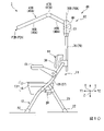
図1に示すように、本実施形態のシャワーシステム1は、椅子11と、シャワー装置41と、を備えている。
椅子11には、公知の椅子を用いることができる。椅子11は、浴室等でも使用可能なように、耐水性を有することが好ましい。例えば、椅子11は、脚部12と、座部13と、背もたれ部14と、肘掛け15と、を備えている。
以下では、椅子11に座る使用者にとっての左右方向(第1方向)X、前後方向(第2方向)Yを基準にして説明する。左右方向Xは、水平面に沿う方向である。前後方向Yは、水平面に沿い、かつ左右方向Xに直交する方向である。左右方向Xの一方側が右側X1であり、左右方向Xの他方側が左側X2である。前後方向Yの一方側が前方Y1であり、前後方向Yの他方側が後方Y2である。
Hereinafter, an embodiment of the shower system according to the present invention will be described with reference to FIGS. 1 to 13.
As shown in FIG. 1, the shower system 1 of the present embodiment includes a chair 11 and a shower device 41.
A known chair can be used as the chair 11. The chair 11 is preferably water resistant so that it can be used in a bathroom or the like. For example, the chair 11 includes a leg portion 12, a seat portion 13, a backrest portion 14, and an armrest 15.
Hereinafter, the description will be made with reference to the left-right direction (first direction) X and the front-back direction (second direction) Y for the user sitting on the chair 11. The left-right direction X is a direction along the horizontal plane. The front-back direction Y is a direction along the horizontal plane and orthogonal to the left-right direction X. One side of the left-right direction X is the right side X1, and the other side of the left-right direction X is the left side X2. One side of the front-rear direction Y is the front Y1, and the other side of the front-rear direction Y is the rear Y2.

座部13は、一対の座板17と、一対の座板17を連結する連結部材18と、を備えている。
座板17は、厚さ方向が上下方向Zとなる板状に形成されている。座板17は、上下方向Zから見た平面視で矩形状を呈している。一対の座板17は、左右方向Xに互いに間隔を空けて並べて配置されている。
連結部材18は、前後方向Yから見たときに、上方が開口するU字状を呈している。連結部材18は、前後方向Yに延び、一対の座板17の下方に配置されている。連結部材18は、一対の座板17の下面同士を連結している。
一対の座板17及び連結部材18は、例えば樹脂により一体に形成されている。
The seat portion 13 includes a pair of seat plates 17 and a connecting member 18 that connects the pair of seat plates 17.
The seat plate 17 is formed in a plate shape having a thickness direction of Z in the vertical direction. The seat plate 17 has a rectangular shape in a plan view seen from the vertical direction Z. The pair of seat plates 17 are arranged side by side at intervals in the left-right direction X.
The connecting member 18 has a U shape that opens upward when viewed from the front-rear direction Y. The connecting member 18 extends in the front-rear direction Y and is arranged below the pair of seat plates 17. The connecting member 18 connects the lower surfaces of the pair of seat plates 17 to each other.
The pair of seat plates 17 and the connecting member 18 are integrally formed of, for example, resin.

一対の座板17の後端部には、後脚21の上端部がそれぞれ固定されている。例えば、後脚21は、アルミニウム、ステンレス等の管材で形成されている。後脚21は、下方に向かうに従い漸次、後方Y2に向かうように傾斜している。一対の後脚21は、左右方向Xに互いに間隔を空けて並べて配置されている。各後脚21の下端部には、樹脂製のキャップ22が取付けられている。
一対の後脚21は、連結部材23により互いに連結されている。
The upper ends of the rear legs 21 are fixed to the rear ends of the pair of seat plates 17. For example, the hind legs 21 are made of a pipe material such as aluminum or stainless steel. The hind legs 21 are gradually inclined toward the rear Y2 as they go downward. The pair of rear legs 21 are arranged side by side at intervals in the left-right direction X. A resin cap 22 is attached to the lower end of each rear leg 21.
The pair of rear legs 21 are connected to each other by a connecting member 23.

一対の後脚21の上端部には、アルミニウム、ステンレス等の硬質の管材でU字状に形成されたフレーム26が回転可能に接続されている。より詳しく説明すると、フレーム26は、左右方向Xに互いに間隔を空けて並べて配置された一対の支持片27と、一対の支持片27の上部同士を接合する連結片28と、を備えている。
支持片27は、下方に向かうに従い漸次、前方Y1に向かうように傾斜している。各支持片27は、長手方向の中間部で、ヒンジ29(一方のヒンジ29は不図示)により後脚21の上端部に回転可能に支持されている。支持片27は、後脚21の上端部に対して左右方向Xに沿う軸線周りに回転可能である。なお、後脚21と支持片27との角度は、所定の角度以上には開かないように、ヒンジ29により規制されている。
各支持片27の下端部には、樹脂製のキャップ32が取付けられている。
A U-shaped frame 26 made of a hard pipe material such as aluminum or stainless steel is rotatably connected to the upper ends of the pair of rear legs 21. More specifically, the frame 26 includes a pair of support pieces 27 arranged side by side at intervals in the left-right direction X, and a connecting piece 28 for joining the upper portions of the pair of support pieces 27.
The support piece 27 is gradually inclined toward the front Y1 as it goes downward. Each support piece 27 is rotatably supported by a hinge 29 (one hinge 29 is not shown) at the upper end of the rear leg 21 at an intermediate portion in the longitudinal direction. The support piece 27 is rotatable about an axis along the left-right direction X with respect to the upper end portion of the rear leg 21. The angle between the rear leg 21 and the support piece 27 is regulated by the hinge 29 so as not to open more than a predetermined angle.
A resin cap 32 is attached to the lower end of each support piece 27.

一対の支持片27は、連結部材30により互いに連結されている。連結部材30は、棒状に形成され、左右方向Xに延びている。なお、一対の支持片27におけるヒンジ29よりも下方の部分、及び一対の後脚21により、脚部12が構成される。
連結片28は、左右方向Xに延びている。なお、連結片28を硬質の樹脂で形成してもよい。
The pair of support pieces 27 are connected to each other by a connecting member 30. The connecting member 30 is formed in a rod shape and extends in the left-right direction X. The leg portion 12 is composed of a portion of the pair of support pieces 27 below the hinge 29 and a pair of rear legs 21.
The connecting piece 28 extends in the left-right direction X. The connecting piece 28 may be made of a hard resin.

図1及び図2に示すように、連結片28の前方Y1には、背板36が配置されている。背板36は、上下方向Zから見たときに、後方Y2に向かって凸となるように湾曲している。背板36は、フレーム26の連結片28に、図示しないボルト等により固定されている。なお、背板36、連結片28、及び一対の支持片27におけるヒンジ29よりも上方の部分により、背もたれ部14が構成される。前述の座部13は、背もたれ部14の前方Y1に配置されている。 As shown in FIGS. 1 and 2, a back plate 36 is arranged at the front Y1 of the connecting piece 28. The back plate 36 is curved so as to be convex toward the rear Y2 when viewed from the vertical direction Z. The back plate 36 is fixed to the connecting piece 28 of the frame 26 by a bolt or the like (not shown). The backrest portion 14 is formed by a portion of the back plate 36, the connecting piece 28, and the pair of support pieces 27 above the hinge 29. The above-mentioned seat portion 13 is arranged in front Y1 of the backrest portion 14.

肘掛け15は、本実施形態では椅子11に一対備えられている。肘掛け15は、前後方向Yに延びている。一対の肘掛け15は、左右方向Xに互いに間隔を空けて並べて配置されている。各肘掛け15の後端部は、支持片27におけるヒンジ29よりも上方の部分に回転可能に支持されている。肘掛け15は、左右方向Xに沿う軸線周りに回転可能である。
肘掛け15は、図1に示す状態から上方に回転可能であるが、図1に示す状態から下方に回転するのが規制されている。
A pair of armrests 15 are provided on the chair 11 in this embodiment. The armrest 15 extends in the front-rear direction Y. The pair of armrests 15 are arranged side by side at intervals in the left-right direction X. The rear end of each armrest 15 is rotatably supported above the hinge 29 of the support piece 27. The armrest 15 is rotatable about an axis along the left-right direction X.
The armrest 15 can rotate upward from the state shown in FIG. 1, but is restricted from rotating downward from the state shown in FIG.

このように構成された椅子11は、図1に示す展開状態から折り畳み可能である。具体的には、一対の支持片27をヒンジ29周りに回転させ、一対の後脚21に対して一対の支持片27をほぼ平行に配置する。各肘掛け15の前端部を上方に移動させ、一対の肘掛け15を一対の支持片27に対してほぼ平行に配置する。
以上の工程により、椅子11を折り畳まれた折り畳み状態になる。なお、椅子11は折り畳みできなくてもよく、肘掛け15を備えなくてもよい。
The chair 11 configured in this way can be folded from the unfolded state shown in FIG. Specifically, the pair of support pieces 27 are rotated around the hinge 29, and the pair of support pieces 27 are arranged substantially parallel to the pair of rear legs 21. The front end of each armrest 15 is moved upward so that the pair of armrests 15 are arranged substantially parallel to the pair of support pieces 27.
By the above steps, the chair 11 is in a folded state. The chair 11 may not be foldable and may not be provided with an armrest 15.

シャワー装置41は、本体42と、第1シャワーアーム(第1腕部)43A及び第2シャワーアーム(第2腕部)43Bと、接続部44と、を備えている。なお、図1に示すシャワーアーム43A,43Bは、後述する使用状態P1A,P1Bである。
シャワーアーム43A,43Bは、本体42を左右方向Xに挟むように配置されている。第1シャワーアーム43Aは本体42の右側X1に配置され、第2シャワーアーム43Bは本体42の左側X2に配置されている。
本実施形態では、第1シャワーアーム43Aの構成と第2シャワーアーム43Bの構成とは、シャワーアーム43A,43Bの間に左右方向Xに直交するように規定される基準面に対して面対称である。このため、第1シャワーアーム43Aの構成を、数字、又は数字及び英小文字に英大文字「A」を付加することで示す。第2シャワーアーム43Bのうち第1シャワーアーム43Aに対応する構成を、第1シャワーアーム43Aと同一の数字、又は数字及び英小文字に英大文字「B」を付加することで示す。これにより、重複する説明を省略する。例えば、第1シャワーアーム43Aの先端部材46Aと第2シャワーアーム43Bの先端部材46Bとは、互いに面対称となる構成である。
The shower device 41 includes a main body 42, a first shower arm (first arm portion) 43A, a second shower arm (second arm portion) 43B, and a connection portion 44. The shower arms 43A and 43B shown in FIG. 1 are in use states P1A and P1B, which will be described later.
The shower arms 43A and 43B are arranged so as to sandwich the main body 42 in the left-right direction X. The first shower arm 43A is arranged on the right side X1 of the main body 42, and the second shower arm 43B is arranged on the left side X2 of the main body 42.
In the present embodiment, the configuration of the first shower arm 43A and the configuration of the second shower arm 43B are plane symmetric with respect to the reference plane defined between the shower arms 43A and 43B so as to be orthogonal to the left-right direction X. be. Therefore, the configuration of the first shower arm 43A is shown by adding an uppercase letter "A" to a number or a number and a lowercase letter. The configuration of the second shower arm 43B corresponding to the first shower arm 43A is shown by adding an uppercase letter "B" to the same number or lowercase letter as the first shower arm 43A. Thereby, the duplicate description will be omitted. For example, the tip member 46A of the first shower arm 43A and the tip member 46B of the second shower arm 43B are configured to be plane-symmetrical with each other.

図3及び図4に示すように、第1シャワーアーム43Aは、先端部材(先端部)46Aと、連結部材(連結部)47Aと、基端部材(基端部)48Aと、を備えている。なお、図3では、本体42を二点鎖線で示している。図4では、先端部材46Aの断面形状を模式的に示している。
先端部材46Aは、先端部が封止された管状に形成されている。先端部材46Aは、前方Y1に向かうに従い漸次、下方に向かうように傾斜している。先端部材46Aには、先端部材46Aの壁部を貫通する吐出孔50Aが形成されている。吐出孔50Aは、先端部材46Aの内部に供給された水Wを外部に吐出する。なお、本明細書における水は、温度が高い、低いによらない一般的な水のことを意味し、常温の水、及びシャワー等に用いられる温度の湯等を含む意味である。
なお、吐出孔50Aが形成されている向きについては、後述する。
As shown in FIGS. 3 and 4, the first shower arm 43A includes a tip member (tip portion) 46A, a connecting member (connecting portion) 47A, and a base end member (base end portion) 48A. .. In FIG. 3, the main body 42 is shown by a chain double-dashed line. FIG. 4 schematically shows the cross-sectional shape of the tip member 46A.
The tip member 46A is formed in a tubular shape with a sealed tip. The tip member 46A is gradually inclined downward toward the front Y1. The tip member 46A is formed with a discharge hole 50A that penetrates the wall portion of the tip member 46A. The discharge hole 50A discharges the water W supplied to the inside of the tip member 46A to the outside. The water in the present specification means general water regardless of whether the temperature is high or low, and includes water at room temperature and hot water having a temperature used for showers and the like.
The direction in which the discharge hole 50A is formed will be described later.

図5に示すように、先端部材46Aの後端部の内周面には、連結溝(嵌合部)51Aが形成されている。なお、図5及び後述する図6では、先端部材46A及び基端部材48Aを二点鎖線で示している。連結溝51Aは、先端部材46Aの内周面の全周にわたって形成されている。
先端部材46Aは、アクリロニトリル・ブタジエン・スチレン樹脂(ABS)樹脂、ポリプロピレン(PP)樹脂等の比較的硬質の材料で形成されている。
As shown in FIG. 5, a connecting groove (fitting portion) 51A is formed on the inner peripheral surface of the rear end portion of the tip member 46A. In FIG. 5 and FIG. 6 described later, the tip member 46A and the base end member 48A are shown by a two-dot chain line. The connecting groove 51A is formed over the entire circumference of the inner peripheral surface of the tip member 46A.
The tip member 46A is made of a relatively hard material such as acrylonitrile-butadiene-styrene resin (ABS) resin and polypropylene (PP) resin.

図5及び図6に示すように、連結部材47Aは、連結部本体(本体部)56Aと、先端側鍔部(被嵌合部)57Aと、基端側鍔部(被嵌合部)58Aと、を備えている。
連結部本体56Aは、円筒状に形成されている。連結部本体56Aは、前方Y1と上方との間の向きに向かって凸となるように湾曲している。
連結部本体56Aの前端部(連結部本体56Aの軸線方向の端部)には、環状部材59Aが同軸に固定されている。環状部材59Aの内径及び連結部本体56Aの前端部の内径は、互いに同等である。環状部材59Aの外径は、連結部本体56Aの前端部の外径よりも小さい。先端側鍔部57Aは、環状部材59Aの前端部における外周面に設けられている。先端側鍔部57Aは、環状部材59Aの外周面から、環状部材59Aの径方向外側に向かって突出している。先端側鍔部57Aの外径は、連結部本体56Aの前端部の外径よりも小さい。先端側鍔部57Aは、環状部材59Aの全周にわたって形成されている。先端側鍔部57Aの前端部は、前方Y1に向かうに従い漸次、外径が小さくなる。
先端側鍔部57Aは、先端部材46Aの連結溝51Aに嵌合している。先端側鍔部57A及び連結溝51Aという簡単な構成で、連結部材47Aと先端部材46Aとが嵌合している。
As shown in FIGS. 5 and 6, the connecting member 47A includes a connecting portion main body (main body portion) 56A, a tip side crossguard portion (fitted portion) 57A, and a base end side crossguard portion (fitted portion) 58A. And have.
The connecting portion main body 56A is formed in a cylindrical shape. The connecting portion main body 56A is curved so as to be convex toward the direction between the front Y1 and the upper side.
An annular member 59A is coaxially fixed to the front end portion of the connecting portion main body 56A (the end portion in the axial direction of the connecting portion main body 56A). The inner diameter of the annular member 59A and the inner diameter of the front end portion of the connecting portion main body 56A are equal to each other. The outer diameter of the annular member 59A is smaller than the outer diameter of the front end portion of the connecting portion main body 56A. The front end side collar portion 57A is provided on the outer peripheral surface of the front end portion of the annular member 59A. The front end side flange portion 57A projects from the outer peripheral surface of the annular member 59A toward the outer side in the radial direction of the annular member 59A. The outer diameter of the front end side flange portion 57A is smaller than the outer diameter of the front end portion of the connecting portion main body 56A. The tip side collar portion 57A is formed over the entire circumference of the annular member 59A. The outer diameter of the front end portion of the front end side collar portion 57A gradually decreases toward the front Y1.
The tip-side crossguard 57A fits into the connecting groove 51A of the tip member 46A. The connecting member 47A and the tip member 46A are fitted to each other with a simple structure of a front end side crossguard 57A and a connecting groove 51A.

連結部本体56Aの後端部(連結部本体56Aの軸線方向の端部)には、環状部材60Aが同軸に固定されている。環状部材60Aの内径及び連結部本体56Aの後端部の内径は、互いに同等である。環状部材60Aの外径は、連結部本体56Aの後端部の外径よりも小さい。基端側鍔部58Aは、環状部材60Aの後端部における外周面に設けられている。基端側鍔部58Aは、環状部材60Aの外周面から、環状部材60Aの径方向外側に向かって突出している。基端側鍔部58Aの外径は、連結部本体56Aの後端部の外径よりも小さい。基端側鍔部58Aは、環状部材60Aの全周にわたって形成されている。基端側鍔部58Aの後端部は、後方Y2に向かうに従い漸次、外径が小さくなる。
連結部材47Aを構成する連結部本体56A、鍔部57A,58A、及び環状部材59A,60Aは、エラストマー、軟質ウレタン、ゴム等の比較的軟質の材料で一体に形成されている。
An annular member 60A is coaxially fixed to the rear end portion of the connecting portion main body 56A (the end portion in the axial direction of the connecting portion main body 56A). The inner diameter of the annular member 60A and the inner diameter of the rear end portion of the connecting portion main body 56A are equal to each other. The outer diameter of the annular member 60A is smaller than the outer diameter of the rear end portion of the connecting portion main body 56A. The base end side crossguard 58A is provided on the outer peripheral surface at the rear end of the annular member 60A. The base end side crossguard 58A projects from the outer peripheral surface of the annular member 60A toward the outer side in the radial direction of the annular member 60A. The outer diameter of the base end side crossguard 58A is smaller than the outer diameter of the rear end of the connecting body 56A. The base end side crossguard 58A is formed over the entire circumference of the annular member 60A. The outer diameter of the rear end portion of the base end side crossguard portion 58A gradually decreases toward the rear Y2.
The connecting portion main body 56A, the collar portions 57A, 58A, and the annular members 59A, 60A constituting the connecting member 47A are integrally formed of a relatively soft material such as an elastomer, soft urethane, and rubber.

なお、連結部本体56Aの内周面に、防水用のシート(フィルム)を配置してもよい。
連結部材47Aを軟質ウレタン樹脂等を用いて発泡により形成する場合には、連結部材47Aの外面に発泡倍率が低いスキン層が形成される。このスキン層により、水漏れを防止してもよい。
A waterproof sheet (film) may be arranged on the inner peripheral surface of the connecting portion main body 56A.
When the connecting member 47A is formed by foaming using a soft urethane resin or the like, a skin layer having a low foaming ratio is formed on the outer surface of the connecting member 47A. This skin layer may prevent water leakage.

図3及び図5に示すように、基端部材48Aは、基端部本体64Aと、連結部材65Aと、環状部材66Aと、連結鍔部67Aと、を備えている。
基端部本体64Aは、管状に形成されている。図5に示すように、基端部本体64Aの前端部の内周面には、連結溝(嵌合部)69Aが形成されている。連結溝69Aは、基端部本体64Aの内周面の全周にわたって形成されている。この連結溝69Aは、連結部材47Aの基端側鍔部58Aに嵌合している。連結部材47Aは、先端部材46Aと基端部材48Aとを連結している。
基端部本体64Aには、先端部材46Aと同様に吐出孔50Aが形成されていることが好ましい。
図3に示すように、連結部材65Aは、基端部本体64Aの後端部に固定されている。連結部材65Aにおける左側X2の外面65aAには、環状部材66Aが固定されている。環状部材66Aの軸線(第1軸線)70Aは、連結部材65Aの外面65aAに直交している。環状部材66A内の流路は、連結部材65Aの内部空間を介して基端部本体64Aの管路に連通している。
As shown in FIGS. 3 and 5, the base end member 48A includes a base end portion main body 64A, a connecting member 65A, an annular member 66A, and a connecting collar portion 67A.
The base end body 64A is formed in a tubular shape. As shown in FIG. 5, a connecting groove (fitting portion) 69A is formed on the inner peripheral surface of the front end portion of the base end portion main body 64A. The connecting groove 69A is formed over the entire circumference of the inner peripheral surface of the base end main body 64A. The connecting groove 69A is fitted to the base end side crossguard 58A of the connecting member 47A. The connecting member 47A connects the tip member 46A and the base end member 48A.
It is preferable that the base end main body 64A is formed with a discharge hole 50A as in the case of the tip member 46A.
As shown in FIG. 3, the connecting member 65A is fixed to the rear end portion of the base end portion main body 64A. An annular member 66A is fixed to the outer surface 65aA of the left side X2 of the connecting member 65A. The axis (first axis) 70A of the annular member 66A is orthogonal to the outer surface 65aA of the connecting member 65A. The flow path in the annular member 66A communicates with the conduit of the base end main body 64A via the internal space of the connecting member 65A.

連結鍔部67Aは、環状部材66Aの左端部における外周面に設けられている。連結鍔部67Aは、環状部材66Aの外周面から、環状部材66Aの径方向外側に向かって突出している。連結鍔部67Aは、環状部材66Aの外周面の全周にわたって形成されている。
基端部材48Aを構成する基端部本体64A、連結部材65A、環状部材66A、及び連結鍔部67Aは、先端部材46Aと同一の材料で形成されている。
このように、先端部材46A及び基端部材48Aよりも、連結部材47Aが柔らかく、変形させやすい。本実施形態では、第1シャワーアーム43Aは、L字状に鈍角で折れた形状である。
The connecting crossguard portion 67A is provided on the outer peripheral surface at the left end portion of the annular member 66A. The connecting crossguard portion 67A projects from the outer peripheral surface of the annular member 66A toward the outside in the radial direction of the annular member 66A. The connecting collar portion 67A is formed over the entire circumference of the outer peripheral surface of the annular member 66A.
The base end main body 64A, the connecting member 65A, the annular member 66A, and the connecting collar portion 67A constituting the base end member 48A are made of the same material as the tip end member 46A.
As described above, the connecting member 47A is softer and more easily deformed than the tip end member 46A and the base end member 48A. In the present embodiment, the first shower arm 43A has an L-shaped obtuse angle.

図1に示すように、第2シャワーアーム43Bは、第1シャワーアーム43Aの先端部材46A、連結部材47A、基端部材48Aと面対称に構成された先端部材46B、連結部材47B、基端部材48Bを備えている。
シャワーアーム43A,43Bの基端部材48A,48B間の距離は、使用者の肩幅程度の長さであることが好ましい。
As shown in FIG. 1, the second shower arm 43B includes a tip member 46A, a connecting member 47A, and a tip member 46B, a connecting member 47B, and a base end member that are symmetrically configured with the tip member 46A, the connecting member 47A, and the base end member 48A of the first shower arm 43A. It is equipped with 48B.
The distance between the base end members 48A and 48B of the shower arms 43A and 43B is preferably about the width of the shoulder of the user.

本体42は、フレーム76と、支持部77と、を備えている。
フレーム76は、アルミニウム、ステンレス等の管材でU字状に形成されている。より詳しく説明すると、フレーム76は、左右方向Xに互いに間隔を空けて並べて配置された一対の支持片79と、一対の支持片79の下端部同士を接合する連結片80と、を備えている。
一対の支持片79は、上下方向Zに延びている。連結片80は、一対の支持片79の下端部において、左右方向Xに延びている。
一対の支持片79の上端部は、支持部77に固定されている。
The main body 42 includes a frame 76 and a support portion 77.
The frame 76 is formed in a U shape by a pipe material such as aluminum or stainless steel. More specifically, the frame 76 includes a pair of support pieces 79 arranged side by side at intervals in the left-right direction X, and a connecting piece 80 for joining the lower ends of the pair of support pieces 79. ..
The pair of support pieces 79 extend in the vertical direction Z. The connecting piece 80 extends in the left-right direction X at the lower ends of the pair of support pieces 79.
The upper ends of the pair of support pieces 79 are fixed to the support portion 77.

図2に示すように、一対の支持片79は、連結片28の後面に接触している。一対の支持片79は、後方Y2から連結金具82により覆われている。連結金具82の前面には、一対の支持片79を収容するための凹部82aが形成されている。連結金具82を通してフレーム26の連結片28に嵌め合うボルト83により、一対の支持片79が椅子11の背もたれ部14に取付けられている。
一方で、連結片28とボルト83との嵌め合いを解除することにより、背もたれ部14から一対の支持片79が取外される。このように、本体42は背もたれ部14に着脱可能であり、背もたれ部14に対して上下方向Zに移動可能である。
なお、シャワー装置41の本体42は、椅子11の背もたれ部14に着脱できない状態で固定されていてもよい。
As shown in FIG. 2, the pair of support pieces 79 are in contact with the rear surface of the connecting piece 28. The pair of support pieces 79 are covered with a connecting metal fitting 82 from the rear Y2. A recess 82a for accommodating a pair of support pieces 79 is formed on the front surface of the connecting metal fitting 82. A pair of support pieces 79 are attached to the backrest portion 14 of the chair 11 by a bolt 83 that is fitted to the connecting piece 28 of the frame 26 through the connecting metal fitting 82.
On the other hand, by disengaging the connecting piece 28 and the bolt 83, the pair of support pieces 79 are removed from the backrest portion 14. In this way, the main body 42 can be attached to and detached from the backrest portion 14, and can move in the vertical direction Z with respect to the backrest portion 14.
The main body 42 of the shower device 41 may be fixed to the backrest portion 14 of the chair 11 in a non-detachable state.

図3に示すように、支持部77の右端部では、支持部77内に形成された流路77aが開口している。前記開口近くの流路77aの軸線は、第1シャワーアーム43Aの環状部材66Aの軸線70Aに一致している。
この流路77aの軸線、すなわち軸線70Aは、図12に示すシャワーシステム1の正面視において、左右方向Xに延びている。より詳しく説明すると、軸線70Aは、上方に向かうに従い漸次、右側X1に向かうように傾斜している。軸線70A、及び第2シャワーアーム43Bに対する軸線70Bは、上方に向かうに従い互いに離間するように、上下方向Zに対して互いに逆方向に傾いている。言い換えれば、軸線70A,70Bは、上下方向Zに沿う基準線L3に対して互いに逆方向に傾いている。例えば、基準線L3と軸線70Aとが上方になす角度θAは、60°程度である。
As shown in FIG. 3, at the right end of the support portion 77, the flow path 77a formed in the support portion 77 is open. The axis of the flow path 77a near the opening coincides with the axis 70A of the annular member 66A of the first shower arm 43A.
The axis of the flow path 77a, that is, the axis 70A, extends in the left-right direction X in the front view of the shower system 1 shown in FIG. More specifically, the axis 70A is gradually inclined toward the right side X1 as it goes upward. The axis 70A and the axis 70B with respect to the second shower arm 43B are inclined in opposite directions with respect to the vertical direction Z so as to be separated from each other toward the upper side. In other words, the axes 70A and 70B are inclined in opposite directions with respect to the reference line L3 along the vertical direction Z. For example, the angle θA formed by the reference line L3 and the axis 70A upward is about 60 °.

軸線70A,70Bは、図11に示すシャワーシステム1の側面視において、上下方向Zに沿って延びている。なお、軸線70Aは、シャワーシステム1の側面視において、上方に向かうに従い漸次、前方Y1に向かうように傾斜していてもよい。
図3に示すように、支持部77のうち、前記開口近くの流路77aの内周面には、本体溝86Aが形成されている。本体溝86Aは、流路77aの内周面の全周にわたって形成されている。本体溝86Aに第1シャワーアーム43Aの連結鍔部67Aが嵌合している。
本体溝78A内で連結鍔部67Aが軸線70A周りに回転することにより、第1シャワーアーム43Aは、支持部77に対して軸線70A周りに回転可能に支持されている。同様に、第2シャワーアーム43Bは、支持部77に対して軸線70B周りに回転可能に支持されている。
The axes 70A and 70B extend along the vertical direction Z in the side view of the shower system 1 shown in FIG. The axis 70A may be inclined toward the front Y1 gradually as it goes upward in the side view of the shower system 1.
As shown in FIG. 3, a main body groove 86A is formed on the inner peripheral surface of the flow path 77a near the opening of the support portion 77. The main body groove 86A is formed over the entire circumference of the inner peripheral surface of the flow path 77a. The connecting collar portion 67A of the first shower arm 43A is fitted in the main body groove 86A.
The connecting collar portion 67A rotates around the axis 70A in the main body groove 78A, so that the first shower arm 43A is rotatably supported around the axis 70A with respect to the support portion 77. Similarly, the second shower arm 43B is rotatably supported around the axis 70B with respect to the support portion 77.

図7は、支持部77と第1シャワーアーム43Aとの軸線70A周りの接続部分を、直線状に展開した模式図である。支持部77における前記開口近くの外面87Aは、第1シャワーアーム43Aにおける連結部材65Aの外面65aAに対向している。 FIG. 7 is a schematic view in which the connecting portion between the support portion 77 and the first shower arm 43A around the axis 70A is linearly developed. The outer surface 87A near the opening in the support portion 77 faces the outer surface 65aA of the connecting member 65A in the first shower arm 43A.

図7に示す支持部77に対する連結部材65Aの位置関係のときに、図1に示すように第1シャワーアーム43Aは使用状態(特定状態)P1Aである。第1シャワーアーム43Aが使用状態P1Aのときから、図7において、支持部77に対して第1シャワーアーム43Aが方向D1に移動することは、図1に示すように支持部77に対して第1シャワーアーム43Aが軸線70A周りの方向D3に回転することを意味する。このとき、第1シャワーアーム43Aの先端部材46Aが下がり、第1シャワーアーム43Aは図8及び図9に示す退避状態P0Aになる。なお、図9は、シャワーアーム43A,43Bが退避状態P0A,P0Bのシャワーシステム1を前後方向Yから見たときの図(正面図)である。
例えば、使用状態P1Aから退避状態P0Aまでの第1シャワーアーム43Aの軸線70A周りの回転角度は、70°である。
As shown in FIG. 1, the first shower arm 43A is in the used state (specific state) P1A when the connecting member 65A is in a positional relationship with the support portion 77 shown in FIG. From the time when the first shower arm 43A is in the used state P1A, in FIG. 7, the movement of the first shower arm 43A in the direction D1 with respect to the support portion 77 means that the first shower arm 43A moves with respect to the support portion 77 with respect to the support portion 77 as shown in FIG. 1 It means that the shower arm 43A rotates in the direction D3 around the axis 70A. At this time, the tip member 46A of the first shower arm 43A is lowered, and the first shower arm 43A is in the retracted state P0A shown in FIGS. 8 and 9. Note that FIG. 9 is a view (front view) of the shower system 1 in the retracted state P0A and P0B when the shower arms 43A and 43B are viewed from the front-rear direction Y.
For example, the rotation angle of the first shower arm 43A from the used state P1A to the retracted state P0A around the axis 70A is 70 °.

一方で、第1シャワーアーム43Aの先端部材46Aが使用状態P1Aのときから、図7において、支持部77に対して第1シャワーアーム43Aが方向D2に移動することは、図1に示すように支持部77に対して第1シャワーアーム43Aが軸線70A周りの方向D4に回転することを意味する。このとき、第1シャワーアーム43Aの先端部材46Aが上がり、図10に示す跳ね上げ状態P2Aになる。
同様に、第2シャワーアーム43Bは、図1に示す使用状態(特定状態)P1Bから先端部材46Bが下がると、図8及び図9に示す退避状態P0Bになる。図1に示す使用状態P1Bから先端部材46Bが上がると、図10に示す跳ね上げ状態P2Bになる。
On the other hand, as shown in FIG. 1, the first shower arm 43A moves in the direction D2 with respect to the support portion 77 in FIG. 7 from the time when the tip member 46A of the first shower arm 43A is in the used state P1A. This means that the first shower arm 43A rotates in the direction D4 around the axis 70A with respect to the support portion 77. At this time, the tip member 46A of the first shower arm 43A rises, and the flip-up state P2A shown in FIG. 10 is reached.
Similarly, when the tip member 46B is lowered from the used state (specific state) P1B shown in FIG. 1, the second shower arm 43B is in the retracted state P0B shown in FIGS. 8 and 9. When the tip member 46B rises from the used state P1B shown in FIG. 1, it becomes the flip-up state P2B shown in FIG.

このように、シャワーアーム43A,43Bの基端部材48A,48Bは、本体42を左右方向Xに挟むように本体42に回転可能に支持されている。そして、第1シャワーアーム43Aの基端部材48Aは、本体42の右端部において、軸線70A周りに回転可能に支持されている。同様に、第2シャワーアーム43Bの基端部材48Bは、本体42の左端部において、軸線70B周りに回転可能に支持されている。
以下では、支持部77と第1シャワーアーム43Aとの接続部分の詳細について説明する。
As described above, the base end members 48A and 48B of the shower arms 43A and 43B are rotatably supported by the main body 42 so as to sandwich the main body 42 in the left-right direction X. The base end member 48A of the first shower arm 43A is rotatably supported around the axis 70A at the right end portion of the main body 42. Similarly, the base end member 48B of the second shower arm 43B is rotatably supported around the axis 70B at the left end of the main body 42.
Hereinafter, the details of the connection portion between the support portion 77 and the first shower arm 43A will be described.

図7に示すように、支持部77の外面87Aには、外面87Aから突出した一対の突起90A,91Aが設けられている。突起90Aは、外面87Aにおける方向D1側に配置され、突起91Aは、外面87Aにおける方向D2側に配置されている。図7は、支持部77の軸線70A周りの形状を展開した形状であるため、実際には、突起90A,91Aは、支持部77の外面87Aに軸線70A周りに互いに間隔を空けて並べて配置されている。
支持部77の外面87Aには、凹部93A,94Aが形成されている。凹部93Aは、突起90Aと突起91Aとの間の外面87Aのうち、突起90A寄りの端部に形成されている。凹部94Aは、外面87Aのうち、突起90Aと突起91Aとの中間部に形成されている。
As shown in FIG. 7, the outer surface 87A of the support portion 77 is provided with a pair of protrusions 90A and 91A protruding from the outer surface 87A. The protrusion 90A is arranged on the direction D1 side of the outer surface 87A, and the protrusion 91A is arranged on the direction D2 side of the outer surface 87A. Since FIG. 7 shows a shape in which the shape around the axis 70A of the support portion 77 is developed, the protrusions 90A and 91A are actually arranged side by side on the outer surface 87A of the support portion 77 around the axis 70A at intervals. ing.
Recesses 93A and 94A are formed on the outer surface 87A of the support portion 77. The recess 93A is formed at the end of the outer surface 87A between the protrusion 90A and the protrusion 91A, which is closer to the protrusion 90A. The recess 94A is formed in the intermediate portion between the protrusion 90A and the protrusion 91A on the outer surface 87A.

外面87Aにおける凹部94Aに対して方向D2側に隣接する部分には、板バネ96Aが固定されていることが好ましい。板バネ96Aは、凹部94Aよりも方向D2側に配置されている。
板バネ96Aの方向D2側の端部は、支持部77の外面87Aに固定されている。一方で、板バネ96Aの方向D1側の端部は、板バネ96Aに外力が作用しない自然状態で外面87Aから離間している。板バネ96Aの方向D1側の端部を外面87Aに向かって付勢すると、板バネ96Aは弾性的に変形し、図7中に二点鎖線による線L1で示すように、板バネ96Aの方向D1側の端部が外面87Aに接触する。また、この付勢力を解放すると、板バネ96Aは元の形状に弾性復帰する。
It is preferable that the leaf spring 96A is fixed to the portion of the outer surface 87A adjacent to the recess 94A on the direction D2 side. The leaf spring 96A is arranged on the direction D2 side of the recess 94A.
The end of the leaf spring 96A on the direction D2 side is fixed to the outer surface 87A of the support portion 77. On the other hand, the end portion of the leaf spring 96A on the direction D1 side is separated from the outer surface 87A in a natural state in which no external force acts on the leaf spring 96A. When the end of the leaf spring 96A on the direction D1 side is urged toward the outer surface 87A, the leaf spring 96A elastically deforms, and as shown by the line L1 by the alternate long and short dash line in FIG. 7, the direction of the leaf spring 96A. The end on the D1 side comes into contact with the outer surface 87A. When this urging force is released, the leaf spring 96A elastically returns to its original shape.

第1シャワーアーム43Aの連結部材65Aの外面65aAには、突起98Aが形成されている。なお、この突起98A、及び前述の支持部77の突起91Aにより、跳ね上げ状態P2Aの第1シャワーアーム43Aの先端部材46Aが上がるのを規制する規制部95Aが構成される。
突起98Aは、支持部77の一対の突起90A,91Aの間に配置されている。支持部77に対して第1シャワーアーム43Aが方向D1に移動すると、突起90Aに突起98Aが係止して、第1シャワーアーム43Aがこれ以上、方向D1に移動できなくなる。一方で、支持部77に対して第1シャワーアーム43Aが方向D2に移動すると、突起91Aに突起98Aが係止して、第1シャワーアーム43Aがこれ以上、方向D2に移動できなくなる。
A protrusion 98A is formed on the outer surface 65aA of the connecting member 65A of the first shower arm 43A. The protrusion 98A and the protrusion 91A of the support portion 77 described above constitute a regulation portion 95A that restricts the tip member 46A of the first shower arm 43A in the flip-up state P2A from rising.
The protrusions 98A are arranged between the pair of protrusions 90A and 91A of the support portion 77. When the first shower arm 43A moves in the direction D1 with respect to the support portion 77, the protrusion 98A is locked to the protrusion 90A, and the first shower arm 43A cannot move in the direction D1 any more. On the other hand, when the first shower arm 43A moves in the direction D2 with respect to the support portion 77, the protrusion 98A is locked to the protrusion 91A, and the first shower arm 43A cannot move in the direction D2 any more.

突起98Aの先端部には、バネ等の付勢部99Aを介して係止部100Aが固定されている。
例えば、係止部100Aは、球状に形成されている。係止部100Aは、支持部77の一対の凹部93A,94Aにそれぞれ係止可能である。一方で、係止部100Aは、支持部77の外面87Aに接触していても、この外面87Aに対して滑らかに(抵抗無く)方向D1及び方向D2に移動することができる。
付勢部99Aは、突起98Aに対して係止部100Aを支持部77の外面87Aに向かって付勢する。
A locking portion 100A is fixed to the tip of the protrusion 98A via an urging portion 99A such as a spring.
For example, the locking portion 100A is formed in a spherical shape. The locking portion 100A can be locked in the pair of recesses 93A and 94A of the support portion 77, respectively. On the other hand, the locking portion 100A can smoothly (without resistance) move in the directions D1 and D2 with respect to the outer surface 87A even if it is in contact with the outer surface 87A of the support portion 77.
The urging portion 99A urges the locking portion 100A against the protrusion 98A toward the outer surface 87A of the support portion 77.

図7に示す状態では、支持部77の凹部94Aに係止部100Aが係止している。このとき、第1シャワーアーム43Aは使用状態P1Aである。
このため、使用状態P1Aである第1シャワーアーム43Aの先端部材46Aを上げたり下げたりするのには、付勢部99Aの付勢力に抗して付勢部99Aを突起98Aに向かって押し返して縮ませる必要がある。すなわち、使用状態P1Aである第1シャワーアーム43Aを軸線70A周りに回転させるためには、付勢部99Aを縮ませる力が必要であり、支持部77の凹部94Aにより第1シャワーアーム43Aの使用状態P1Aが位置決めされている。
In the state shown in FIG. 7, the locking portion 100A is locked in the recess 94A of the supporting portion 77. At this time, the first shower arm 43A is in the used state P1A.
Therefore, in order to raise or lower the tip member 46A of the first shower arm 43A in the used state P1A, the urging portion 99A is pushed back toward the protrusion 98A against the urging force of the urging portion 99A. It needs to be shrunk. That is, in order to rotate the first shower arm 43A in the used state P1A around the axis 70A, a force for contracting the urging portion 99A is required, and the first shower arm 43A is used by the recess 94A of the support portion 77. State P1A is positioned.

さらに、板バネ96Aを備えるため、使用状態P1Aである第1シャワーアーム43Aの先端部材46Aを上げるためには、板バネ96Aの方向D1側の端部を外面87Aに向かって変形させる必要がある。使用状態P1Aである第1シャワーアーム43Aが使用者の意図することなく跳ね上げ状態P2Aにならないように、シャワー装置41に板バネ96Aが備えらている。
係止部100Aが、凹部94A及び板バネ96Aを一度方向D2側に越えると、第1シャワーアーム43Aを方向D2に移動させるのに、付勢部99A又は板バネ96Aを変形させる必要が無くなる。すなわち、第1シャワーアーム43Aを軸線70A周りに容易に回転できるようになる。
Further, since the leaf spring 96A is provided, in order to raise the tip member 46A of the first shower arm 43A in the used state P1A, it is necessary to deform the end portion of the leaf spring 96A on the direction D1 side toward the outer surface 87A. .. The shower device 41 is provided with a leaf spring 96A so that the first shower arm 43A, which is in the use state P1A, does not enter the flip-up state P2A unintentionally by the user.
Once the locking portion 100A crosses the recess 94A and the leaf spring 96A toward the direction D2, it is not necessary to deform the urging portion 99A or the leaf spring 96A in order to move the first shower arm 43A in the direction D2. That is, the first shower arm 43A can be easily rotated around the axis 70A.

図11、図12に、シャワーアーム43A,43Bが使用状態P1A,P1Bであるときのシャワーシステム1の側面図、正面図をそれぞれ示す。シャワーシステム1のシャワーアーム43A,43Bは、使用者が椅子11の座部13に座り、使用状態P1A,P1Bにしたうえで使用される。使用状態P1A,P1Bのシャワーアーム43A,43Bの先端部材46A,46Bは、図8及び図9に示す退避状態P0A,P0Bの先端部材46A,46Bよりも位置が上がっている。 11 and 12 show side views and front views of the shower system 1 when the shower arms 43A and 43B are in use states P1A and P1B, respectively. The shower arms 43A and 43B of the shower system 1 are used after the user sits on the seat portion 13 of the chair 11 and is in the used state P1A and P1B. The tip members 46A and 46B of the shower arms 43A and 43B in the used states P1A and P1B are positioned higher than the tip members 46A and 46B in the retracted states P0A and P0B shown in FIGS. 8 and 9.

図12に示す正面視において、シャワーアーム43A,43Bが使用状態P1A,P1Bであるときに、シャワーアーム43A,43Bはそれぞれ上下方向Zに沿って延びるように配置されている。言い換えると、図11及び図12に示すように、使用状態P1A,P1Bであるシャワーアーム43A,43Bは、左右方向Xに直交する基準面SA,SB上にそれぞれ配置されている。
また、図11に示すように、使用状態P1A,P1Bであるシャワーアーム43A,43Bは、椅子11の背もたれ部14よりも、前方Y1に向かって延びるように配置されている。シャワーアーム43A,43Bの吐出孔50A,50Bは、シャワーアーム43A,43Bが使用状態P1A,P1Bであるときに、水が後方Y2と下方との間の斜めの向き等に吐出するように形成されている。
なお、シャワーアーム43A,43Bは、使用状態P1A,P1Bのときに、少なくとも吐出孔50A,50Bが形成されている部分が背もたれ部14よりも、前方Y1に向かって延びるように配置されていればよい。
In the front view shown in FIG. 12, when the shower arms 43A and 43B are in the used states P1A and P1B, the shower arms 43A and 43B are arranged so as to extend along the vertical direction Z, respectively. In other words, as shown in FIGS. 11 and 12, the shower arms 43A and 43B in the usage states P1A and P1B are arranged on the reference planes SA and SB orthogonal to the left-right direction X, respectively.
Further, as shown in FIG. 11, the shower arms 43A and 43B in the used states P1A and P1B are arranged so as to extend toward the front Y1 from the backrest portion 14 of the chair 11. The discharge holes 50A and 50B of the shower arms 43A and 43B are formed so that water is discharged in an oblique direction between the rear Y2 and the lower side when the shower arms 43A and 43B are in the used states P1A and P1B. ing.
If the shower arms 43A and 43B are arranged so that at least the portions where the discharge holes 50A and 50B are formed extend toward the front Y1 from the backrest portion 14 when the shower arms 43A and 43B are in use P1A and P1B. good.

第1シャワーアーム43Aは軸線70Aに対して先端部材46A側に延びているため、、第1シャワーアーム43Aは自身の自重(自身に作用する重力)により、軸線70A周りに先端部材46Aが下がる向きに回転しようとする。
使用状態P1Aにある第1シャワーアーム43Aがこのように回転することを、支持部77の凹部94Aに係止部100Aが係止していることと、付勢部99Aの弾性力とにより防いでいる。
Since the first shower arm 43A extends toward the tip member 46A with respect to the axis 70A, the first shower arm 43A has a direction in which the tip member 46A is lowered around the axis 70A due to its own weight (gravity acting on itself). Try to rotate to.
The first shower arm 43A in the operating state P1A is prevented from rotating in this way by the locking portion 100A being locked to the recess 94A of the support portion 77 and the elastic force of the urging portion 99A. There is.

一方で、図8及び図9に示すように、退避状態P0A,P0Bであるときのシャワーアーム43A,43Bは、使用者がシャワーアーム43A,43Bを使用しないときの状態である。このとき、シャワーアーム43A,43Bの先端部材46A,46Bは、図11、図12に示すシャワーアーム43A,43Bが使用状態P1A,P1Bであるときの先端部材46A,46Bよりも下がっている。
図9に示すように、退避状態P0A,P0Bであるときのシャワーアーム43A,43Bは、下方に向かうに従い漸次、互いに左右方向Xに離間するように配置されている。シャワーアーム43A,43Bは、全体としてハ字状(上下を逆にしたV字状)である。
より詳しく説明すると、第1シャワーアーム43Aは、下方に向かうに従い漸次、右側X1に向かうように傾斜している。一方で、第2シャワーアーム43Bは、下方に向かうに従い漸次、左側X2に向かうように傾斜している。
On the other hand, as shown in FIGS. 8 and 9, the shower arms 43A and 43B in the retracted states P0A and P0B are the states when the user does not use the shower arms 43A and 43B. At this time, the tip members 46A and 46B of the shower arms 43A and 43B are lower than the tip members 46A and 46B when the shower arms 43A and 43B shown in FIGS. 11 and 12 are in the used states P1A and P1B.
As shown in FIG. 9, the shower arms 43A and 43B in the retracted states P0A and P0B are arranged so as to be gradually separated from each other in the left-right direction X as they go downward. The shower arms 43A and 43B have a V-shape (upside down V-shape) as a whole.
More specifically, the first shower arm 43A is gradually inclined toward the right side X1 as it goes downward. On the other hand, the second shower arm 43B is gradually inclined toward the left side X2 as it goes downward.

前述のように軸線70A,70Bが上下方向Zに対して傾いているため、シャワーアーム43A,43Bを使用状態P1A,P1Bから退避状態P0A,P0Bにすると、シャワーアーム43A,43Bは、下方に向かうに従い漸次、互いに離間する。
なお、退避状態P0A,P0Bのとき、シャワーアーム43A,43Bの先端部材46A,46B間の距離は、椅子11の一対の肘掛け15全体の左右方向Xの長さよりも長い。さらに、退避状態P0A,P0Bのときのシャワーアーム43A,43Bの先端部材46A,46B間の距離は、使用状態P1A,P1Bのときのシャワーアーム43A,43Bの先端部材46A,46B間の距離よりも長い。
図8に示す側面視において、シャワーアーム43A,43Bの先端部材46A,46Bは、基端部材48A,48Bの下方にそれぞれ配置されている。シャワーアーム43A,43Bが退避状態P0A,P0Bであるときに、シャワーアーム43A,43Bの吐出孔50A,50Bは後方Y2を向いている。
Since the axes 70A and 70B are tilted with respect to the vertical direction Z as described above, when the shower arms 43A and 43B are changed from the used states P1A and P1B to the retracted states P0A and P0B, the shower arms 43A and 43B move downward. Gradually, they are separated from each other.
In the retracted states P0A and P0B, the distance between the tip members 46A and 46B of the shower arms 43A and 43B is longer than the length of the entire pair of armrests 15 of the chair 11 in the left-right direction X. Further, the distance between the tip members 46A and 46B of the shower arms 43A and 43B in the retracted states P0A and P0B is larger than the distance between the tip members 46A and 46B of the shower arms 43A and 43B in the used states P1A and P1B. long.
In the side view shown in FIG. 8, the tip members 46A and 46B of the shower arms 43A and 43B are arranged below the base end members 48A and 48B, respectively. When the shower arms 43A and 43B are in the retracted states P0A and P0B, the discharge holes 50A and 50B of the shower arms 43A and 43B face the rear Y2.

シャワーアーム43A,43Bが退避状態P0A,P0Bのときに、突起98A及び係止部100Aは、図7において二点鎖線による線L5で示す位置に配置されている。そして、支持部77の凹部93Aに係止部100Aが係止していて、支持部77の突起90Aに突起98Aが方向D2側から係止している。このため、支持部77に対して第1シャワーアーム43Aがこれ以上方向D1に移動できなくなり、シャワーアーム43A,43Bの先端部材46A,46Bが、これ以上下がらなくなる。 When the shower arms 43A and 43B are in the retracted states P0A and P0B, the protrusion 98A and the locking portion 100A are arranged at the positions indicated by the alternate long and short dash line L5 in FIG. The locking portion 100A is locked to the recess 93A of the support portion 77, and the protrusion 98A is locked to the protrusion 90A of the support portion 77 from the direction D2 side. Therefore, the first shower arm 43A cannot move in the direction D1 any more with respect to the support portion 77, and the tip members 46A and 46B of the shower arms 43A and 43B cannot be lowered any more.

図10に示すように、跳ね上げ状態P2A,P2Bは、使用者が使用状態P1A,P1Bで使用していたシャワーアーム43A,43Bの先端部材46A,46Bを上方に移動させた(跳ね上げた)状態である。シャワーアーム43A,43Bでは、使用状態P1A,P1Bよりも跳ね上げ状態P2A,P2Bの方が、先端部材46A,46Bが上方に位置する。
このとき、突起98A及び係止部100Aは、図7において二点鎖線による線L6で示す位置に配置されている。支持部77の突起91Aに、突起98Aが方向D1側から係止している。このため、支持部77に対して第1シャワーアーム43Aがこれ以上方向D2に移動できなくなり、シャワーアーム43A,43Bの先端部材46A,46Bが、これ以上上がらなくなる。
As shown in FIG. 10, in the flip-up states P2A and P2B, the tip members 46A and 46B of the shower arms 43A and 43B used by the user in the use states P1A and P1B were moved upward (jumped up). It is in a state. In the shower arms 43A and 43B, the tip members 46A and 46B are located higher in the flip-up states P2A and P2B than in the used states P1A and P1B.
At this time, the protrusion 98A and the locking portion 100A are arranged at the positions indicated by the alternate long and short dash line L6 in FIG. The protrusion 98A is locked to the protrusion 91A of the support portion 77 from the direction D1 side. Therefore, the first shower arm 43A cannot move in the direction D2 any more with respect to the support portion 77, and the tip members 46A and 46B of the shower arms 43A and 43B cannot be raised any more.

なお、跳ね上げ状態P2Aの第1シャワーアーム43Aの先端部材46Aは、自重により使用状態P1Aの第1シャワーアーム43Aの先端部材46Aの位置まで下がる。
この第1シャワーアーム43Aの自重に逆らって、跳ね上げ状態P2Aと使用状態P1Aとの間では、第1シャワーアーム43Aを軸線70A周りにほぼ外力を作用させることなく回転させることができるようにバネを設けてもよい。このバネは、第1シャワーアーム43Aの先端部材46Aが上がるように、第1シャワーアーム43Aを軸線70A周りに付勢する。
The tip member 46A of the first shower arm 43A in the flip-up state P2A is lowered to the position of the tip member 46A of the first shower arm 43A in the use state P1A due to its own weight.
A spring is provided so that the first shower arm 43A can be rotated around the axis 70A with almost no external force acting between the flip-up state P2A and the used state P1A against the weight of the first shower arm 43A. May be provided. This spring urges the first shower arm 43A around the axis 70A so that the tip member 46A of the first shower arm 43A rises.

図1に示すように、接続部44は、例えば、ホース103等が着脱可能に接続されるコネクタである。接続部44は、本体42の支持部77の後面に固定されている。接続部44には、ホース103を介して外部から水が供給される。接続部44に供給された水は、図示しない2又分岐、及び支持部77の流路77aを通して、シャワーアーム43A,43Bに供給される。 As shown in FIG. 1, the connecting portion 44 is, for example, a connector to which a hose 103 or the like is detachably connected. The connecting portion 44 is fixed to the rear surface of the supporting portion 77 of the main body 42. Water is supplied to the connecting portion 44 from the outside via the hose 103. The water supplied to the connecting portion 44 is supplied to the shower arms 43A and 43B through a bifurcated branch (not shown) and a flow path 77a of the supporting portion 77.

次に、以上のように構成されたシャワーシステム1の動作について説明する。
予め、椅子11は折り畳み状態になっていて、シャワー装置41は椅子11に取付けられている。シャワーアーム43A,43Bは、退避状態P0A,P0Bになっている。退避状態P0A,P0Bであるシャワーアーム43A,43Bは、正面視において、基端部材48A,48Bから下方に向かうに従い漸次互いに左右方向Xに離間するように配置されているため、シャワーアーム43A,43Bが椅子11の一対の肘掛け15を左右方向Xの外側に避けやすい。
Next, the operation of the shower system 1 configured as described above will be described.
The chair 11 is in a folded state in advance, and the shower device 41 is attached to the chair 11. The shower arms 43A and 43B are in the retracted states P0A and P0B. Since the shower arms 43A and 43B in the retracted states P0A and P0B are arranged so as to be gradually separated from each other in the left-right direction X as they go downward from the base end members 48A and 48B in the front view, the shower arms 43A and 43B Is easy to avoid the pair of armrests 15 of the chair 11 outside the left-right direction X.

使用者は、図1に示すように、椅子11を展開状態にし、浴室B等の床B1上にシャワーシステム1を設置する。このとき、図示しない水栓にホース103を接続し、このホース103を、シャワー装置41の接続部44に接続する。水栓から出る水の温度を、例えば35℃~40℃程度の所望の温度に設定し、水栓を開ける。
水栓から流れ出る水は、当初は15℃~25℃程度の常温である。水栓から流れ出る水は、ホース103、接続部44、支持部77の流路77aを通して、シャワーアーム43A,43Bに供給され、吐出孔50A,50Bから外部に吐出する。このとき、シャワーアーム43A,43Bの吐出孔50A,50Bは後方Y2を向いているため、常温の水が使用者に掛かることが抑制される。
As shown in FIG. 1, the user deploys the chair 11 and installs the shower system 1 on the floor B1 of the bathroom B or the like. At this time, a hose 103 is connected to a faucet (not shown), and the hose 103 is connected to the connection portion 44 of the shower device 41. The temperature of the water coming out of the faucet is set to a desired temperature of, for example, about 35 ° C. to 40 ° C., and the faucet is opened.
The water flowing out of the faucet is initially at room temperature of about 15 ° C to 25 ° C. The water flowing out of the faucet is supplied to the shower arms 43A and 43B through the flow path 77a of the hose 103, the connection portion 44, and the support portion 77, and is discharged to the outside from the discharge holes 50A and 50B. At this time, since the discharge holes 50A and 50B of the shower arms 43A and 43B face the rear Y2, it is possible to prevent the user from being exposed to water at room temperature.

使用者は、背もたれ部14の前方Y1で椅子11に座る。一定の時間が経過すると、吐出孔50A,50Bから吐出する水の温度が所望の温度になる。
図13に示すように、使用者Pは、シャワーアーム43A,43Bの先端部材46A,46Bを上げて、シャワーアーム43A,43Bを使用状態P1A,P1Bにする。シャワーアーム43A,43Bの連結部材47A,47Bが柔らかい場合には、使用者Pはシャワーアーム43A,43Bの基端部材48A,48Bを持ち上げる。
The user sits on the chair 11 at the front Y1 of the backrest portion 14. After a certain period of time, the temperature of the water discharged from the discharge holes 50A and 50B becomes a desired temperature.
As shown in FIG. 13, the user P raises the tip members 46A and 46B of the shower arms 43A and 43B to bring the shower arms 43A and 43B into the used states P1A and P1B. When the connecting members 47A and 47B of the shower arms 43A and 43B are soft, the user P lifts the base end members 48A and 48B of the shower arms 43A and 43B.

使用状態P1A,P1Bであるシャワーアーム43A,43Bは、正面視においてそれぞれ上下方向Zに沿って延び、使用状態P1A,P1Bのときのシャワーアーム43A,43Bの先端部材46A,46B間の距離は、退避状態P0A,P0Bのときのシャワーアーム43A,43Bの先端部材46A,46B間の距離よりも短い。このため、シャワーアーム43A,43Bの先端部材46A,46Bは、退避状態P0A,P0Bのときよりも使用者Pの左右方向Xの中心に近づく。
退避状態P0A,P0Bにおいて左右方向Xに互いに離間していたシャワーアーム43A,43Bの先端部材46A,46Bは、使用状態P1A,P1Bにおいて使用者Pの肩幅程度の長さに近づくため、退避状態P0A,P0Bから使用状態P1A,P1Bになる過程で、シャワーアーム43A,43Bが椅子11の一対の肘掛け15や、使用者Pの身体等に干渉しにくい。
The shower arms 43A and 43B in the used states P1A and P1B extend along the vertical direction Z in the front view, respectively, and the distance between the tip members 46A and 46B of the shower arms 43A and 43B in the used states P1A and P1B is It is shorter than the distance between the tip members 46A and 46B of the shower arms 43A and 43B in the retracted states P0A and P0B. Therefore, the tip members 46A and 46B of the shower arms 43A and 43B are closer to the center of the user P in the left-right direction X than in the retracted states P0A and P0B.
Since the tip members 46A and 46B of the shower arms 43A and 43B separated from each other in the left-right direction X in the retracted states P0A and P0B approach the length of the shoulder width of the user P in the used states P1A and P1B, the retracted state P0A , The shower arms 43A and 43B are less likely to interfere with the pair of armrests 15 of the chair 11 and the body of the user P in the process of changing from P0B to the used states P1A and P1B.

図7における線L5で示す位置に配置され、支持部77の凹部93Aに係止していた係止部100Aは方向D2に移動し、支持部77の凹部94Aに係止する。
図13に示すように、使用者Pは、シャワーアーム43A,43Bの吐出孔50A,50Bから吐出する水Wを浴び、シャワーを浴びる。
なお、使用者Pは、シャワーアーム43A,43Bを退避状態P0A,P0Bにして、自身の身体を洗ってもよい。この際に、シャワーアーム43A,43Bが退避状態P0A,P0Bであるため、シャワーアーム43A,43Bが身体を洗う作業の支障になりにくい。
The locking portion 100A, which is arranged at the position indicated by the line L5 in FIG. 7 and has been locked in the recess 93A of the support portion 77, moves in the direction D2 and locks in the recess 94A of the support portion 77.
As shown in FIG. 13, the user P bathes in the water W discharged from the discharge holes 50A and 50B of the shower arms 43A and 43B, and takes a shower.
The user P may wash his / her own body by setting the shower arms 43A and 43B in the retracted states P0A and P0B. At this time, since the shower arms 43A and 43B are in the retracted states P0A and P0B, the shower arms 43A and 43B are less likely to interfere with the work of washing the body.

使用者Pは、シャワーを浴び終えると、シャワーアーム43A,43Bを退避状態P0A,P0Bにする。浴室Bの水栓を閉じる。 When the user P finishes taking a shower, the shower arms 43A and 43B are brought into the retracted states P0A and P0B. Close the faucet in bathroom B.

仮に、シャワーアーム43A,43Bを使用状態P1A,P1Bにしてシャワーを浴びている使用者Pが、緊急事態が発生したためにシャワーシステム1からとっさに脱出する場合には、以下の手順を行う。
使用者Pは、手等により、使用状態P1A,P1Bであるシャワーアーム43A,43Bをそれぞれ持ち上げる(跳ね上げる)。図7において、支持部77の凹部94Aに係止していた係止部100Aは方向D2に移動し、板バネ96Aを線L1で示すように弾性的に変形させて乗り越える。
If the user P taking a shower with the shower arms 43A and 43B in use states P1A and P1B suddenly escapes from the shower system 1 due to an emergency, the following procedure is performed.
The user P lifts (jumps up) the shower arms 43A and 43B, which are in the used states P1A and P1B, by hand or the like, respectively. In FIG. 7, the locking portion 100A locked in the recess 94A of the supporting portion 77 moves in the direction D2 and elastically deforms the leaf spring 96A as shown by the line L1 to overcome it.

係止部100Aは図7における線L6で示す位置に配置され、支持部77の突起91Aに第1シャワーアーム43Aの突起98Aが方向D1側から係止して、シャワーアーム43A,43Bの先端部材46A,46Bがこれ以上上がらなくなる。 The locking portion 100A is arranged at the position shown by the line L6 in FIG. 7, and the protrusion 98A of the first shower arm 43A is locked to the protrusion 91A of the support portion 77 from the direction D1 side, and the tip members of the shower arms 43A and 43B. 46A and 46B cannot be raised any more.

椅子11の座部13とシャワーアーム43A,43Bの先端部材46A,46Bとが上下方向Zに広がったため、使用者Pはシャワーアーム43A,43Bにほぼ干渉することなく椅子11から立ち上がり、シャワーシステム1から脱出する。使用状態P1A,P1Bであるシャワーアーム43A,43Bの先端部材46A,46Bを上げる際には、シャワーアーム43A,43Bが固定されないため、使用者Pの身体がシャワーアーム43A,43Bに接触すると、ほぼ抵抗なくシャワーアーム43A,43Bの先端部材46A,46Bが上がる。
使用者Pが手等をシャワーアーム43A,43Bから放すと、シャワーアーム43A,43Bの先端部材46A,46Bは、シャワーアーム43A,43Bの自重により板バネ96A,96Bを変形させながら、使用状態P1A,P1Bのシャワーアーム43A,43Bの先端部材46A,46Bの位置までそれぞれ下がる。このとき、支持部77の凹部94Aに係止部100Aが係止する。
Since the seat portion 13 of the chair 11 and the tip members 46A and 46B of the shower arms 43A and 43B spread in the vertical direction Z, the user P stands up from the chair 11 with almost no interference with the shower arms 43A and 43B, and the shower system 1 Escape from. When raising the tip members 46A and 46B of the shower arms 43A and 43B which are the usage states P1A and P1B, the shower arms 43A and 43B are not fixed. The tip members 46A and 46B of the shower arms 43A and 43B rise without resistance.
When the user P releases his / her hand or the like from the shower arms 43A and 43B, the tip members 46A and 46B of the shower arms 43A and 43B deform the leaf springs 96A and 96B by the weight of the shower arms 43A and 43B while using the state P1A. , P1B shower arms 43A and 43B are lowered to the positions of the tip members 46A and 46B, respectively. At this time, the locking portion 100A is locked in the recess 94A of the supporting portion 77.

また、使用者Pがシャワーシステム1から脱出する際に、シャワーアーム43A,43Bの連結部材47A,47Bを変形させ、先端部材46A,46Bを所望の方向に曲げてもよい。
例えば、使用者Pは、第1シャワーアーム43Aの連結部材47Aを変形させて、例えば先端部材46Aを持ち上げる等した後で、椅子11から前方Y1に脱出する。この際に、先端部材46A及び基端部材48Aよりも連結部材47Aが柔らかいため、使用者Pが先端部材46Aを操作することにより、先端部材46Aよりも柔らかい連結部材47Aを変形させることができる。連結部材47Aが変形するため、第1シャワーアーム43Aの基端部材48Aに過剰な力が作用しなく、第1シャワーアーム43Aが破損するのが防止できる。
以上のように、緊急事態が発生した場合でも、使用者Pはシャワーシステム1から容易に脱出することができる。
Further, when the user P escapes from the shower system 1, the connecting members 47A and 47B of the shower arms 43A and 43B may be deformed and the tip members 46A and 46B may be bent in a desired direction.
For example, the user P deforms the connecting member 47A of the first shower arm 43A, lifts the tip member 46A, for example, and then escapes from the chair 11 to the front Y1. At this time, since the connecting member 47A is softer than the tip member 46A and the base end member 48A, the user P can operate the tip member 46A to deform the connecting member 47A which is softer than the tip member 46A. Since the connecting member 47A is deformed, an excessive force does not act on the base end member 48A of the first shower arm 43A, and it is possible to prevent the first shower arm 43A from being damaged.
As described above, even in the event of an emergency, the user P can easily escape from the shower system 1.

なお、前述のシャワーシステム1や水栓を操作する使用者は、実際にシャワーを浴びてシャワーシステム1を使用する使用者(以下、実際の使用者と言う)に限定されず、実際の使用者の補助者としてシャワーシステム1を使用する介助者であってもよい。
すなわち、実際の使用者がシャワーシステム1等を操作するのが困難である場合には、介助者がシャワーシステム1の操作等を行う。
The user who operates the shower system 1 or the faucet described above is not limited to the user who actually takes a shower and uses the shower system 1 (hereinafter referred to as an actual user), and is an actual user. It may be an assistant who uses the shower system 1 as an assistant.
That is, when it is difficult for the actual user to operate the shower system 1 or the like, the caregiver operates the shower system 1 or the like.

以上説明したように、本実施形態のシャワー装置41によれば、使用者Pは背もたれ部14の前方Y1で椅子11に座り、シャワーアーム43A,43Bを使用状態P1A,P1Bにして、接続部44から供給されシャワーアーム43A,43Bにおける背もたれ部14よりも前方Y1に延びている部分の吐出孔50A,50Bから吐出する水Wに当たることによりシャワーを浴びる。
この際に、緊急事態が発生したため等により、シャワー装置41から使用者Pが脱出する場合には、連結部材47Aを変形させて、例えば先端部材46Aを持ち上げる等して、第1シャワーアーム43Aを使用者Pがシャワー装置41から脱出するのに支障がないように形状にする。従って、使用状態P1Aである第1シャワーアーム43Aから使用者Pが容易に脱出することができる。
As described above, according to the shower device 41 of the present embodiment, the user P sits on the chair 11 at the front Y1 of the backrest portion 14, sets the shower arms 43A and 43B to the operating states P1A and P1B, and sets the connecting portion 44. The shower is taken by hitting the water W discharged from the discharge holes 50A and 50B of the portion of the shower arms 43A and 43B that extends forward Y1 from the backrest portion 14.
At this time, when the user P escapes from the shower device 41 due to an emergency or the like, the connecting member 47A is deformed, for example, the tip member 46A is lifted to raise the first shower arm 43A. The shape is formed so that the user P does not have any trouble in escaping from the shower device 41. Therefore, the user P can easily escape from the first shower arm 43A, which is in the used state P1A.

連結部材47Aは、連結部本体56Aと、先端部材46Aの連結溝51Aに嵌合する先端側鍔部57Aと、を備える。このため、連結溝51A及び先端側鍔部57Aという簡単な構成で、第1シャワーアーム43Aの先端部材46Aと連結部材47Aとを嵌合させることができる。
シャワー装置41が、第2シャワーアーム43Bを備える。このため、第1シャワーアーム43Aの吐出孔50Aから吐出する水Wだけでなく、第1シャワーアーム43Aとともに本体42を左右方向Xに挟んだ第2シャワーアーム43Bの吐出孔50Bから吐出する水Wにより、使用者Pにシャワーを浴びさせることができる。
The connecting member 47A includes a connecting portion main body 56A and a tip side crossguard portion 57A that fits into the connecting groove 51A of the tip member 46A. Therefore, the tip member 46A and the connecting member 47A of the first shower arm 43A can be fitted with a simple configuration of the connecting groove 51A and the tip side flange portion 57A.
The shower device 41 includes a second shower arm 43B. Therefore, not only the water W discharged from the discharge hole 50A of the first shower arm 43A, but also the water W discharged from the discharge hole 50B of the second shower arm 43B sandwiching the main body 42 in the left-right direction X together with the first shower arm 43A. Therefore, the user P can take a shower.

また、本実施形態のシャワーシステム1によれば、使用状態P1A,P1Bであるシャワーアーム43A,43Bから使用者Pが容易に脱出可能なシャワー装置41を用いてシャワーシステム1を構成することができる。 Further, according to the shower system 1 of the present embodiment, the shower system 1 can be configured by using the shower device 41 in which the user P can easily escape from the shower arms 43A and 43B which are the usage states P1A and P1B. ..

以上、本発明の一実施形態について図面を参照して詳述したが、具体的な構成はこの実施形態に限られるものではなく、本発明の要旨を逸脱しない範囲の構成の変更、組み合わせ、削除等も含まれる。
例えば、前記実施形態では、シャワー装置41は、第2シャワーアーム43Bを備えなくてもよい。
この場合、第1シャワーアーム43Aは、退避状態P0A及び跳ね上げ状態P2Bに回転できなくてもよい。嵌合部が先端部材46Aの連結溝51Aであり、被嵌合部が連結部材47Aの先端側鍔部57Aであるとした。しかし、嵌合部が鍔部であり、被嵌合部が鍔部に嵌合する溝である等してもよい。基端部材48Aの連結溝69A、連結部材47Aの基端側鍔部58Aについても同様である。
Although one embodiment of the present invention has been described in detail with reference to the drawings, the specific configuration is not limited to this embodiment, and the configuration is changed, combined, or deleted without departing from the gist of the present invention. Etc. are also included.
For example, in the above embodiment, the shower device 41 does not have to include the second shower arm 43B.
In this case, the first shower arm 43A may not be able to rotate in the retracted state P0A and the flip-up state P2B. It is assumed that the fitting portion is the connecting groove 51A of the tip member 46A, and the fitting portion is the tip side crossguard portion 57A of the connecting member 47A. However, the fitting portion may be a flange portion, and the fitted portion may be a groove that fits into the collar portion. The same applies to the connecting groove 69A of the base end member 48A and the base end side crossguard 58A of the connecting member 47A.

先端部材46A又は基端部材48Aと連結部材47Aとは、接着等により接合されてもよい。第1シャワーアーム43Aは、本体42の左側X2や、本体42における左右方向Xの中間部に配置されていてもよい。
椅子11は、一対の肘掛け15を備えなくてもよい。
本体42は、浴室Bに、椅子11とは別に設けられた支柱等の支持部に取付けられてもよい。浴室Bは、ユニットバスでもよいし、在来工法による浴室であってもよい。
The tip member 46A or the base end member 48A and the connecting member 47A may be joined by adhesion or the like. The first shower arm 43A may be arranged on the left side X2 of the main body 42 or in the middle portion of the main body 42 in the left-right direction X.
The chair 11 does not have to include a pair of armrests 15.
The main body 42 may be attached to a support portion such as a support column provided separately from the chair 11 in the bathroom B. The bathroom B may be a unit bath or a bathroom by a conventional construction method.

1 シャワーシステム
11 椅子
14 背もたれ部
41 シャワー装置
42 本体
43A 第1シャワーアーム(第1腕部)
43B 第2シャワーアーム(第2腕部)
44 接続部
46A 先端部材(先端部)
47A 連結部材(連結部)
48A,48B 基端部材(基端部)
50A,50B 吐出孔
51A 連結溝(嵌合部)
56A 連結部本体(本体部)
57A 先端側鍔部(被嵌合部)
58A 基端側鍔部(被嵌合部)
69A 連結溝(嵌合部)
70A,70B 軸線
P 使用者
P1A 使用状態(特定状態)
W 水
X 左右方向(第1方向)
Y 前後方向(第2方向)
Y1 前方(一方側)
1 Shower system 11 Chair 14 Backrest 41 Shower device 42 Main body 43A 1st shower arm (1st arm)
43B 2nd shower arm (2nd arm)
44 Connection part 46A Tip member (tip part)
47A connecting member (connecting part)
48A, 48B base end member (base end part)
50A, 50B Discharge hole 51A Connecting groove (fitting part)
56A Connecting part main body (main body part)
57A Tip side crossguard (fitted part)
58A Base end side crossguard (fitted part)
69A connecting groove (fitting part)
70A, 70B Axis line P User P1A Usage state (specific state)
W Water X Left-right direction (first direction)
Y Front-back direction (second direction)
Y1 front (one side)

Claims (4)

外部から水が供給される接続部を有する本体と、
第1方向に延びる軸線周りに基端部が前記本体に回転可能に支持され、前記接続部から内部に供給された前記水を外部に吐出する吐出孔が形成された第1腕部と、
を備え、
前記第1腕部の特定状態では、前記第1腕部の先端部の少なくとも一部は、前記第1方向に交差する第2方向の一方側に延び、
前記第1腕部の基端部及び前記第1腕部の先端部よりも、前記第1腕部の基端部と前記第1腕部の先端部とを連結する前記第1腕部の連結部が柔らかいことを特徴とするシャワー装置。
A main body with a connection part where water is supplied from the outside,
A first arm portion in which a base end portion is rotatably supported by the main body around an axis extending in the first direction and a discharge hole for discharging the water supplied to the inside from the connection portion is formed.
With
In the specific state of the first arm, at least a part of the tip of the first arm extends to one side of the second direction intersecting the first direction.
Connection of the first arm portion that connects the base end portion of the first arm portion and the tip end portion of the first arm portion rather than the base end portion of the first arm portion and the tip end portion of the first arm portion. A shower device characterized by a soft part.
前記連結部は、
筒状に形成された本体部と、
前記本体部の軸線方向の端部に設けられ、前記第1腕部の基端部又は前記第1腕部の先端部に形成された嵌合部に嵌合する被嵌合部と、
を備える請求項1に記載のシャワー装置。
The connecting part
The main body formed in a tubular shape and
A fitted portion provided at the axial end of the main body and fitted to a fitting portion formed at the base end portion of the first arm portion or the tip end portion of the first arm portion.
The shower device according to claim 1.
前記第1方向に延びる軸線周りに基端部が前記本体に回転可能に支持され、前記接続部から内部に供給された前記水を外部に吐出する吐出孔が形成された第2腕部を備え、
前記第1腕部の基端部及び前記第2腕部の基端部は、前記本体を前記第1方向に挟むように配置されている請求項1又は2に記載のシャワー装置。
A second arm portion is provided such that a base end portion is rotatably supported by the main body around an axis extending in the first direction and a discharge hole for discharging the water supplied to the inside from the connection portion is formed. ,
The shower device according to claim 1 or 2, wherein the base end portion of the first arm portion and the base end portion of the second arm portion are arranged so as to sandwich the main body in the first direction.
請求項1から3のいずれか一項に記載のシャワー装置と、
使用者が座る椅子と、
を備え、
前記椅子の背もたれ部に、前記シャワー装置の前記本体が取付けられることを特徴とするシャワーシステム。
The shower device according to any one of claims 1 to 3 and
The chair on which the user sits and
With
A shower system characterized in that the main body of the shower device is attached to the backrest portion of the chair.
JP2018096604A 2018-05-18 2018-05-18 Shower equipment and shower system Active JP7103846B2 (en)

Priority Applications (1)

Application Number Priority Date Filing Date Title
JP2018096604A JP7103846B2 (en) 2018-05-18 2018-05-18 Shower equipment and shower system

Applications Claiming Priority (1)

Application Number Priority Date Filing Date Title
JP2018096604A JP7103846B2 (en) 2018-05-18 2018-05-18 Shower equipment and shower system

Publications (2)

Publication Number Publication Date
JP2019198585A JP2019198585A (en) 2019-11-21
JP7103846B2 true JP7103846B2 (en) 2022-07-20

Family

ID=68611464

Family Applications (1)

Application Number Title Priority Date Filing Date
JP2018096604A Active JP7103846B2 (en) 2018-05-18 2018-05-18 Shower equipment and shower system

Country Status (1)

Country Link
JP (1) JP7103846B2 (en)

Families Citing this family (1)

* Cited by examiner, † Cited by third party
Publication number Priority date Publication date Assignee Title
CN109276173A (en) * 2018-10-08 2019-01-29 江门市蓬江区硕泰电器有限公司 Spray equipment

Citations (7)

* Cited by examiner, † Cited by third party
Publication number Priority date Publication date Assignee Title
JP2001000502A (en) 1999-06-18 2001-01-09 Kawai Musical Instr Mfg Co Ltd Shower device
JP2003052783A (en) 2001-08-08 2003-02-25 Choshu Sangyo Kk Shower unit with heart rate detecting function
JP2005065799A (en) 2003-08-20 2005-03-17 Inax Corp Shower device
JP2005113605A (en) 2003-10-10 2005-04-28 Masuda Jushi Kagaku Kogyo Kk Shower head support device for bathroom
JP3133235U (en) 2007-04-23 2007-07-05 泰男 桑原 Shower equipment
WO2012117796A1 (en) 2011-03-01 2012-09-07 Okubo Takayasu Shower device
CN106901635A (en) 2017-03-06 2017-06-30 曲金龙 Sit, found dual-purpose type shower

Family Cites Families (1)

* Cited by examiner, † Cited by third party
Publication number Priority date Publication date Assignee Title
JPH0439882Y2 (en) * 1987-11-16 1992-09-18

Patent Citations (7)

* Cited by examiner, † Cited by third party
Publication number Priority date Publication date Assignee Title
JP2001000502A (en) 1999-06-18 2001-01-09 Kawai Musical Instr Mfg Co Ltd Shower device
JP2003052783A (en) 2001-08-08 2003-02-25 Choshu Sangyo Kk Shower unit with heart rate detecting function
JP2005065799A (en) 2003-08-20 2005-03-17 Inax Corp Shower device
JP2005113605A (en) 2003-10-10 2005-04-28 Masuda Jushi Kagaku Kogyo Kk Shower head support device for bathroom
JP3133235U (en) 2007-04-23 2007-07-05 泰男 桑原 Shower equipment
WO2012117796A1 (en) 2011-03-01 2012-09-07 Okubo Takayasu Shower device
CN106901635A (en) 2017-03-06 2017-06-30 曲金龙 Sit, found dual-purpose type shower

Also Published As

Publication number Publication date
JP2019198585A (en) 2019-11-21

Similar Documents

Publication Publication Date Title
JP7385777B2 (en) shower equipment
JP4339829B2 (en) Folding chair for bathroom
US8052217B2 (en) Adjustable ergonomic chair
JP7103846B2 (en) Shower equipment and shower system
JP7103847B2 (en) Shower equipment and shower system
JP2017070543A (en) Folding chair for nursing care
WO2017221312A1 (en) Chair and seat support mechanism
JP7294743B2 (en) shower facilities
JP7213102B2 (en) Bathroom chair with shower unit
JP7099697B2 (en) Shower system
JP6817665B1 (en) Toilet armrest device
JP7409738B2 (en) cover
CN112401714A (en) Cover
JP7323252B2 (en) cover
KR102597868B1 (en) safety seat
WO2013145557A1 (en) Seat
JP4490722B2 (en) Nursing shower chair
JP7054290B1 (en) Toilet railing device
KR20080022622A (en) Multi capacity chair for vehicle
JP2020089440A (en) Shower device and shower system
KR102518356B1 (en) Foldable bath chair
JP7148142B2 (en) Portable toilet with manual washer
EP0556237A1 (en) Sanitary seat.
JP4057932B2 (en) Folding chair for bathroom
JP2020199031A (en) Shower device

Legal Events

Date Code Title Description
A711 Notification of change in applicant

Free format text: JAPANESE INTERMEDIATE CODE: A711

Effective date: 20181128

A521 Request for written amendment filed

Free format text: JAPANESE INTERMEDIATE CODE: A821

Effective date: 20181128

A521 Request for written amendment filed

Free format text: JAPANESE INTERMEDIATE CODE: A523

Effective date: 20190419

A521 Request for written amendment filed

Free format text: JAPANESE INTERMEDIATE CODE: A821

Effective date: 20190419

A621 Written request for application examination

Free format text: JAPANESE INTERMEDIATE CODE: A621

Effective date: 20210308

A977 Report on retrieval

Free format text: JAPANESE INTERMEDIATE CODE: A971007

Effective date: 20220112

A131 Notification of reasons for refusal

Free format text: JAPANESE INTERMEDIATE CODE: A131

Effective date: 20220125

TRDD Decision of grant or rejection written
A01 Written decision to grant a patent or to grant a registration (utility model)

Free format text: JAPANESE INTERMEDIATE CODE: A01

Effective date: 20220628

A61 First payment of annual fees (during grant procedure)

Free format text: JAPANESE INTERMEDIATE CODE: A61

Effective date: 20220707

R150 Certificate of patent or registration of utility model

Ref document number: 7103846

Country of ref document: JP

Free format text: JAPANESE INTERMEDIATE CODE: R150