JP7101957B2 - Pachinko machine - Google Patents
Pachinko machine Download PDFInfo
- Publication number
- JP7101957B2 JP7101957B2 JP2017227524A JP2017227524A JP7101957B2 JP 7101957 B2 JP7101957 B2 JP 7101957B2 JP 2017227524 A JP2017227524 A JP 2017227524A JP 2017227524 A JP2017227524 A JP 2017227524A JP 7101957 B2 JP7101957 B2 JP 7101957B2
- Authority
- JP
- Japan
- Prior art keywords
- effect
- image
- opening
- special
- game
- Prior art date
- Legal status (The legal status is an assumption and is not a legal conclusion. Google has not performed a legal analysis and makes no representation as to the accuracy of the status listed.)
- Active
Links
Images


Description
本発明は、パチンコ遊技機などの遊技機に関する。 The present invention relates to a gaming machine such as a pachinko gaming machine.
従来、始動口への遊技球の入賞を契機に表示装置を用いた表示演出を実行可能な遊技機が知られている(例えば、特許文献1参照)。 Conventionally, there is known a gaming machine capable of performing a display effect using a display device when a gaming ball wins a prize at a starting port (see, for example, Patent Document 1).
このような遊技機では、キャラクタ画像や図柄などを用いた表示演出をおこなうことができる。 In such a gaming machine, it is possible to perform a display effect using a character image, a pattern, or the like.
しかしながら、上記の遊技機によっても、遊技の興趣を向上させるための技術については、なお改善の余地があった。 However, even with the above-mentioned gaming machines, there is still room for improvement in techniques for improving the enjoyment of gaming.
本発明は、上述した課題を解決するためになされたものであり、遊技の興趣の向上を図ることを目的とする。 The present invention has been made to solve the above-mentioned problems, and an object of the present invention is to improve the interest of the game.
本発明は、上述の課題の少なくとも一部を解決するためになされたものであり、以下の適用例として実現することが可能である。なお、本欄における括弧内の参照符号や補足説明等は、本発明の理解を助けるために、後述する実施形態との対応関係を示したものであって、本発明を何ら限定するものではない。 The present invention has been made to solve at least a part of the above-mentioned problems, and can be realized as the following application example. It should be noted that the reference numerals and supplementary explanations in parentheses in this column indicate the correspondence with the embodiments described later in order to assist the understanding of the present invention, and do not limit the present invention in any way. ..
[適用例1]
遊技者が操作可能な操作手段と、
前記操作手段の画像を表示可能な表示手段と、を備えた遊技機であって、
前記操作手段の画像の一部を利用して、当該操作手段が操作可能となるまでの時間表示を行い、
前記操作手段が操作可能となるまでの時間表示を行うとともに、当該操作手段の操作が保留されていることを示す文字表示を、前記操作手段の画像とは別の特別の画像を用いて行い、
前記操作手段の画像の前面側に重ねて前記特別の画像を表示するとともに、前記操作手段の画像の傾斜角度に前記文字表示を合わせるよう前記特別の画像を表示する、
ことを特徴とする遊技機。
[Application example 1]
Operation means that can be operated by the player,
A gaming machine provided with a display means capable of displaying an image of the operation means.
Using a part of the image of the operating means, the time until the operating means becomes operable is displayed.
The time until the operation means becomes operable is displayed, and the character display indicating that the operation of the operation means is suspended is performed by using a special image different from the image of the operation means.
The special image is displayed on the front side of the image of the operating means, and the special image is displayed so as to match the character display with the tilt angle of the image of the operating means.
A gaming machine characterized by that.
本発明によれば、遊技の興趣を向上させることができる。 According to the present invention, it is possible to improve the interest of the game.
<第1実施形態>
1.遊技機の構造
図1は、本発明の一実施形態としての遊技機1の正面図である。以下では、遊技機1の左右方向を、遊技機1に対面する遊技者から見た左右方向に一致させて説明する。また、遊技機1の前方向は、遊技機1から遊技者に向かう方向として説明し、遊技機1の後方向は、遊技者から遊技機1に向かう方向として説明する。
<First Embodiment>
1. 1. Structure of the gaming machine FIG. 1 is a front view of the
遊技機1は、遊技者の発射操作に基づいて遊技球を発射させ、特定の入賞装置に遊技球が入賞すると、その入賞に基づいて所定数の遊技球を遊技者に払い出すパチンコ遊技機である。遊技機1は、遊技機枠50と、遊技盤2とを備え、遊技機枠50の内側に遊技盤2が取り付けられている。遊技機枠50は、前枠(前枠部)53のほか、遊技機の外郭部を形成する外枠(基枠部)と、外枠の内側において遊技盤2が取り付けられる内枠と、を備えている。前枠(前枠部)53は、外枠および内枠の前方側に配置される縦長方形状のユニットであり、ハンドル60と、打球供給皿(上皿)61と、余剰球受皿(下皿)62と、演出ボタン63と、剣部材64と、剣ボタン65と、枠ランプ66と、スピーカ67と、枠可動体600とを備えている。前枠53の中央には開口部が形成されており、開口部を介して、遊技盤2の遊技領域3を視認することができる。
The
ハンドル60は、前枠53の右側の下端に配置され、回転角度に応じた発射強度で遊技球を発射させる。打球供給皿(上皿)61は、前枠53の下方に設けられ、遊技球を貯留する。余剰球受皿(下皿)62は、打球供給皿(上皿)61の下方に配置され、打球供給皿61に収容しきれない遊技球を貯留する。演出ボタン63は、打球供給皿(上皿)61の近傍に配置された操作部であり、遊技の進行に伴って実行される演出時などに遊技者によって操作(押圧)される。剣部材64は、剣の形を模した操作部であり、遊技の進行に伴って実行される演出時等に遊技者が下方向に押し込むことができる。剣ボタン65は、剣部材64の上端部分、すなわち、剣の柄の端部に設けられた操作部であり、遊技の進行に伴って実行される演出時などに遊技者によって操作(押圧)される。剣部材64は、剣部材64全体を下方に押し込む第1の操作と、先端の剣ボタン65を押圧する第2の操作の異なる2つの操作を実行可能に構成されている。枠ランプ66は、前枠53の開口部周辺に配置され、遊技中などに発光演出をおこなう。スピーカ67は、前枠53の左上方と右上方に配置され、遊技中などに音演出をおこなう。枠可動体600は、前枠53の上部に設けられた可動式のいわゆるギミックである。枠可動体600は、前枠53の内部に格納されている格納状態から、前枠53の上方に突出する露出状態に変位可能に構成されている。
The
遊技盤2は、遊技領域3と、レール部材4と、盤ランプ5と、画像表示装置7と、センター装飾体10と、固定入賞装置(ヘソ)19と、普通可変入賞装置(電チュー)22と、ゲート(スルーチャッカー)28と、第1大入賞装置(第1アタッカー)31と、第2大入賞装置(第2アタッカー)36と、普通入賞口27と、アウト口16と、表示器類40と、を備えている。
The
遊技領域3は、ハンドル60の操作によって発射された遊技球が流下する領域であり、遊技球を誘導する複数の遊技釘が突設されている。レール部材4は、遊技領域3の左側端部に配置され、ハンドル60の操作によって発射された遊技球を遊技領域3の上方に向けて誘導する。盤ランプ5は、遊技領域3の背面側に配置され、遊技領域3の背面側から光を照射する。
The
画像表示装置7は、遊技領域3の中央付近に設けられ、表示画面7aを備えている。画像表示装置7は、液晶表示装置であってもよいし、有機EL表示装置、プラズマディスプレイ、プロジェクター、ドットマトリクスなどの他の画像表示装置であってもよい。画像表示装置7の表示画面7aは、演出図柄(装飾図柄)8L、8C、8Rが可変表示(変動表示ともいう)される演出図柄表示領域と、保留画像9A、9Bが表示される保留画像表示領域と、保留消化画像9Cが表示される保留消化画像表示領域と、を有している。保留画像9A、9Bは、保留を表す画像であり、保留アイコンまたは第1保留アイコンとも呼ぶ。保留消化画像9Cは、当該保留を表す画像であり、当該保留アイコンまたは第2保留アイコンとも呼ぶ。第1保留アイコンと第2保留アイコンとを総称して、単に保留アイコンとも呼ぶ。
The
演出図柄表示領域は、「左」「中」「右」の3つの図柄表示エリアを含んでいる。左の図柄表示エリアには左演出図柄(左装飾図柄)8Lが表示される。中の図柄表示エリアには中演出図柄(中装飾図柄)8Cが表示される。右の図柄表示エリアには右演出図柄(右装飾図柄)8Rが表示される。演出図柄8L、8C、8Rは、例えば「1」~「9」までの数字を表した複数の図柄によって構成されている。演出図柄8L、8C、8Rの変動表示は、後述する第1特別図柄および第2特別図柄の変動表示と同期している。画像表示装置7は、左、中、右の図柄表示エリアに表示する演出図柄の組み合わせによって、後述の第1特別図柄表示器41aおよび第2特別図柄表示器41bによって表示される第1特別図柄および第2特別図柄の可変表示の結果(大当たり抽選結果)を、遊技者にわかりやすく表示することができる。
The effect symbol display area includes three symbol display areas of "left", "middle", and "right". The left effect symbol (left decorative symbol) 8L is displayed in the symbol display area on the left. The middle effect symbol (intermediate decorative symbol) 8C is displayed in the symbol display area inside. The right effect symbol (right decorative symbol) 8R is displayed in the symbol display area on the right. The
例えば、大当たりに当選した場合には「777」などのゾロ目で演出図柄を停止表示する。はずれであった場合には「637」などのバラケ目で演出図柄を停止表示する。これにより、遊技者による遊技の進行状況の把握が容易となる。遊技者は、大当たり抽選結果を第1特別図柄表示器41aや第2特別図柄表示器41bのほか、画像表示装置7によって把握することができる。なお、図柄表示エリアの位置は固定的でなくてもよい。また、演出図柄の変動表示の態様としては、上下方向にスクロールする態様であってもよいしそれ以外の態様であってもよい。各抽選結果に応じてどのような演出図柄の組み合わせを停止表示するかは上記に限定されず任意に設定することができる。以後、演出図柄8L、8C、8Rを表示する演出を「演出図柄変動演出」、「装飾図柄の変動演出」または、単に「変動演出」とも呼ぶ。なお、この装飾図柄の変動演出は、特別図柄が変動開始してから停止するまでの期間(特別図柄変動期間とも呼ぶ)における演出を1回の変動演出(1サイクルの変動演出)としてカウントする。従って、特別図柄が変動開始してから停止するまでの期間に、装飾図柄を仮停止させる場合があったとしても、当該仮停止の演出は、装飾図柄の変動演出に含まれる。
For example, when a big hit is won, the effect symbol is stopped and displayed with doublet such as "777". If it is out of alignment, the staging pattern is stopped and displayed at a random number such as "637". This makes it easier for the player to grasp the progress of the game. The player can grasp the jackpot lottery result by the first
画像表示装置7は、演出図柄変動演出のほか、大当たり遊技(特別遊技の一例)に並行しておこなわれる大当たり演出や、客待ち用のデモ演出などを表示画面7aに表示することができる。演出図柄変動演出では、演出図柄のほか、背景画像やキャラクタ画像などの演出画像も表示されてもよい。また、画像表示装置7は、演出図柄に加え、特別図柄が変動中であることを示唆したり、特別図柄の抽選結果を示唆したりすることが可能な識別表示(第四図柄、図示省略)を、表示画面7aに表示してもよい。なお、識別表示(第四図柄)は、遊技領域3に設けられたLEDなどの発光器によって表示させてもよい。
The
保留画像表示領域は、後述の第1特図保留の記憶数に応じて保留画像9Aを表示する第1保留表示エリアと、後述の第2特図保留の記憶数に応じて保留画像9Bを表示する第2保留表示エリアとを含んでいる。保留画像9A、9Bの表示によって、後述の第1特図保留表示器43aに表示される第1特図保留の記憶数と、第2特図保留表示器43bに表示される第2特図保留の記憶数を、遊技者にわかりやすく表示することができる。保留消化画像表示領域は、保留消化画像9Cを表示する保留消化表示エリアを含んでいる。保留消化画像9Cは、表示画面7aで現在変動中の演出図柄(演出図柄8L、8C、8R)に対応しており、保留消化画像9Cの表示によって、第1特図保留または第2特図保留が消化(後述の「特図保留の消化」)されることを、遊技者にわかりやすく表示することができる。
The reserved image display area displays a first reserved display area for displaying the
センター装飾体10は、遊技領域3の中央付近であって、画像表示装置7の前方に配置されている。センター装飾体10には、可動式のいわゆるギミックである盤可動体15(可動役物15とも呼ぶ)が取り付けられている。センター装飾体10の下部には、ステージ部11が形成されている。ステージ部11は、ステージ部11の上面を転動する遊技球を後述の第1始動口20へと誘導可能な形状を有している。センター装飾体10の左下方には、ワープ部12が設けられている。ワープ部12は、遊技球が流入する入口部と遊技球が流出する出口部とを備え、入口部から流入した遊技球を出口部からステージ部11に流出させる。
The
固定入賞装置(ヘソ)19は、遊技領域3における画像表示装置7の下方に配置され、遊技球の入球し易さが常に変わらない第1始動口(第1始動入賞口、第1入球口、固定始動口)20を備えている。第1始動口20への遊技球の入賞は、第1特別図柄の抽選(大当たり抽選)の契機となっている。言い換えれば、第1始動口20への遊技球の入賞は、大当たり乱数等の取得および大当たり判定等の契機となっている。
The fixed winning device (navel) 19 is arranged below the
普通可変入賞装置(電チュー)22は、遊技領域3における第1始動口20の下方に配置され、第2始動口(第2始動入賞口、第2入球口、可変始動口)21を備えている。第2始動口21への遊技球の入賞は、第2特別図柄の抽選(大当たり抽選)の契機となっている。電チュー22は、第2始動口21の前方に可動部材23を備えており、可動部材23の作動によって第2始動口21を開閉する。可動部材23は、電チューソレノイド24(図3)によって駆動される。第2始動口21は、可動部材23が開状態のとき遊技球が入球可能である。なお、電チュー22は、可動部材23が開状態のときの方が閉状態のときよりも第2始動口21への入球が容易であればよく、閉状態のときに第2始動口21への入球が可能であってもよい。
The ordinary variable winning device (electric chew) 22 is arranged below the first starting opening 20 in the
ゲート(スルーチャッカー)28は、遊技領域3における第1大入賞装置(第1アタッカー)31の上方に配置されており、遊技球が通過可能に構成されている。ゲート28への遊技球の通過は、電チュー22を開放するか否かを決定する普通図柄抽選の契機となっている。言い換えれば、ゲート28への遊技球の通過は、普通図柄乱数(当たり乱数)の取得および当たり判定等の契機となっている。
The gate (through chucker) 28 is arranged above the first big winning device (first attacker) 31 in the
ここで、「特別図柄の抽選」とは、第1始動口20または第2始動口21に遊技球が入賞したときに、特別図柄判定用の乱数を取得し、この取得した乱数を予め定められた「大当たり」に対応する値と比較することにより、大当たりか否かを判定する処理をいう。この「大当たり」の抽選結果は即座に遊技者に報知されるわけではなく、後述の第1特別図柄表示器41aまたは第2特別図柄表示器41bにおいて特別図柄の変動表示がおこなわれ、所定の変動時間を経過したところで、抽選結果に対応する特別図柄が停止表示(確定表示)され、遊技者に抽選結果が報知される。画像表示装置7では、特別図柄の変動表示と同期して演出図柄を変動表示する図柄合わせゲームが行われ、この図柄合わせゲームによって、より効果的に大当りの抽選結果が遊技者に報知される。
Here, the "special symbol lottery" means that when a game ball wins a prize in the
また、「普通図柄の抽選」とは、ゲート28を遊技球が通過したときに、普通図柄判定用の乱数を取得し、この取得した乱数を予め定められた「当り」に対応する値と比較することにより、当りか否かを判定する処理をいう。この普通図柄の抽選結果についても、ゲート28を遊技球が通過して即座に抽選結果が報知されるわけではなく、後述の普通図柄表示器42において普通図柄の変動表示がおこなわれ、所定の変動時間を経過したところで、抽選結果に対応する普通図柄が確定表示(点灯または消灯)され、遊技者に抽選結果が報知される。
Further, in the "ordinary symbol lottery", when the game ball passes through the
第1大入賞装置(第1アタッカー、第1特別可変入賞装置)31は、遊技領域3における第1始動口20の右上方に配置され、第1大入賞口(第1特別入賞口)30と、V領域39と、非V領域70と、V開閉部材71とを備えている。第1大入賞口30は、スイング式の開閉動作により遊技球の受け入れを許容または阻害する開閉部材(第1特別入賞口開閉部材)32を備えている。開閉部材32は、第1大入賞口ソレノイド33(図3)によって駆動される。第1大入賞口30は、開閉部材32が開状態のとき遊技球が入球可能となる。
The first big winning device (first attacker, first special variable winning device) 31 is arranged on the upper right side of the
第1大入賞装置31は内部に、V領域(特定領域)39と、V領域センサ39a(図3)と、非V領域(非特定領域)70と、非V領域センサ70a(図3)と、第1大入賞口センサ30a(図3)と、V開閉部材71と、V開閉部材ソレノイド73(図3)と、を備えている。V領域(特定領域)39および非V領域(非特定領域)70は、第1大入賞装置31の内部において、第1大入賞口30を通過した遊技球が通過可能な領域として構成されている。第1大入賞口センサ30aは、V領域39および非V領域70の上流に配置され、第1大入賞口30への遊技球の入賞を検知する。V領域センサ39aは、V領域39に配置され、V領域39への遊技球の通過を検知する。非V領域センサ70aは、非V領域70に配置され、非V領域70への遊技球の通過を検知する。V開閉部材71は、第1大入賞口30を通過した遊技球をV領域39または非V領域70のいずれかに振り分ける。V開閉部材ソレノイド73は、V開閉部材71を駆動する。V開閉部材71は、回転移動(遊技盤2に対して時計回りおよび反時計回り)するように構成され、V開閉部材ソレノイド73の通電時には、原点位置から反時計回りに回転して遊技球をV領域39に振り分ける第1の状態(回動状態)となり、V開閉部材ソレノイド73の非通電時には、原点に位置して遊技球を非V領域70に振り分ける第2の状態(停止状態)となる。なお、V開閉部材71は、回転移動に限らず、第1大入賞口30を通過した遊技球をV領域39または非V領域70のいずれかに振り分ける機能を有しておればよく、例えば、遊技盤2に対して左右方向に移動するように構成してもよい。すなわち、V開閉部材ソレノイド73の通電時には、遊技球をV領域39に振り分ける退避状態(第1の状態)となり、V開閉部材ソレノイド73の非通電時には、遊技球を非V領域70に振り分ける進出状態(第2の状態)となるように構成してもよい。なお、遊技機1では、V領域39への遊技球の通過が後述の高確率状態への移行の契機となっている。つまり、V領域39は、確変作動口となっている。一方、非V領域70は、確変作動口となっていない。本実施形態の第1大入賞装置31は、さらに、第1大入賞装置31から排出される遊技球数を計数する第1大入賞装置排出センサ(図示しない)を備えている。第1大入賞装置排出センサは、V領域39と非V領域70が下流で合流した地点に設けられており、V領域センサ39aまたは非V領域センサ70aを通過した遊技球数を計数する。
The first large winning
第2大入賞装置(第2アタッカー、第2特別可変入賞装置)36は、遊技領域3における第1大入賞口30の右上方に配置され、第2大入賞口(第2特別入賞口)35を備えている。第2大入賞口35は、スイング式の開閉動作により遊技球の受け入れを阻害または許容する開閉部材(第2特別入賞口開閉部材、可動部材)37を備えている。開閉部材37は、第2大入賞口ソレノイド38(図3)によって駆動される。第2大入賞口35は、開閉部材37が開状態のとき遊技球が入球可能となる。
The second big winning device (second attacker, second special variable winning device) 36 is arranged on the upper right side of the first big winning
普通入賞口27は、遊技領域3の下部に設けられている。なお、普通入賞口27の数は任意に設定することができる。アウト口16は、遊技領域3の下部に設けられており、いずれの入賞口にも入賞しなかった遊技球を遊技領域3の外へ排出する。表示器類40は、遊技盤2の右側中央付近に配置されている。表示器類40の詳細については後述する。
The ordinary winning opening 27 is provided in the lower part of the
遊技領域3には、左右方向の中央より左側の左遊技領域3Aと、右側の右遊技領域3Bとがある。左遊技領域3Aを遊技球が流下するように遊技球を発射する打ち方を「左打ち」と呼ぶ。一方、右遊技領域3Bを遊技球が流下するように遊技球を発射する打ち方を「右打ち」と呼ぶ。遊技機1では、左打ちにて第1始動口20への入賞を狙うことができる。一方、右打ちにてゲート28への通過、第2始動口21、第1大入賞口30、および、第2大入賞口35への入賞が狙うことができるように構成されている。
The
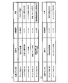
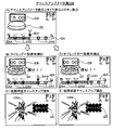
図2は、表示器類40の拡大図である。表示器類40は、第1特別図柄表示器41aと、第2特別図柄表示器41bと、普通図柄表示器42と、第1特図保留表示器43aと、第2特図保留表示器43bと、普図保留表示器44と、を含んでいる。第1特別図柄表示器41aは、第1特別図柄を可変表示する。第2特別図柄表示器41bは、第2特別図柄を可変表示する。普通図柄表示器42は、普通図柄を可変表示する。第1特図保留表示器43aは、第1特別図柄表示器41aの作動保留(第1特図保留)の記憶数を表示する。第2特図保留表示器43bは、第2特別図柄表示器41bの作動保留(第2特図保留)の記憶数を表示する。普図保留表示器44は、普通図柄表示器42の作動保留(普図保留)の記憶数を表示する。第1特別図柄の可変表示は、第1始動口20への遊技球の入賞を契機としておこなわれる。第2特別図柄の可変表示は、第2始動口21への遊技球の入賞を契機としておこなわれる。以下では、第1特別図柄および第2特別図柄を総称して「特別図柄」とも呼ぶ。また、第1特別図柄表示器41aおよび第2特別図柄表示器41bを総称して「特別図柄表示器41」とも呼ぶ。また、第1特図保留表示器43aおよび第2特図保留表示器43bを総称して「特図保留表示器43」とも呼ぶ。
FIG. 2 is an enlarged view of the
特別図柄表示器41は、特別図柄(識別情報)を可変表示(変動表示)した後、停止表示することによって第1始動口20または第2始動口21への入賞に基づく抽選(特別図柄当たり抽選、大当たり抽選)の結果を報知する。停止表示される特別図柄(停止図柄、可変表示の表示結果として導出表示される特別図柄)は、特別図柄抽選によって複数種類の特別図柄の中から選択された一つの特別図柄である。停止図柄が予め定めた大当たり停止態様の特別図柄(大当たり図柄)である場合には、停止表示された大当たり図柄の種類(当選した大当たりの種類)に応じた開放パターンにて第1大入賞口30または第2大入賞口35を開放させる特別遊技(大当たり遊技)がおこなわれる。なお、特別遊技における大入賞口(第1大入賞口30および第2大入賞口35)の開放パターンについては後述する。
The
特別図柄表示器41は、横並びに配された8個のLEDから構成されており、その点灯態様によって特別図柄当たり抽選の結果に応じた特別図柄を表示する。例えば、大当たり(後述の複数種類の大当たりのうちの一つ)に当選した場合には、「○○●●○○●●」(○:点灯、●:消灯)というように左から1,2,5,6番目にあるLEDが点灯した大当たり図柄を表示する。ハズレである場合には、「●●●●●●●○」というように一番右にあるLEDのみが点灯したハズレ図柄を表示する。ハズレ図柄として全てのLEDを消灯させる態様を採用してもよい。特別図柄が停止表示される前には、所定の変動時間にわたって特別図柄の変動表示(可変表示)がなされる。変動表示の態様は、例えば、左から右へ光が繰り返し流れるように各LEDが点灯してもよい。変動表示の態様は、各LEDが停止表示(特定の態様での点灯表示)されていなければ、上記態様に限定されず、任意の点灯態様とすることができる。例えば、変動表示の態様は、全LEDが一斉に点滅してもよい。
The
遊技機1では、第1始動口20または第2始動口21への遊技球の入賞(入球)があると、その入賞に対して取得した大当たり乱数等の各種乱数の値(数値情報)は、特図保留記憶領域85(図5)に一旦記憶される。具体的には、第1始動口20への入賞であれば、第1特図保留として第1特図保留記憶領域85a(図5)に記憶され、第2始動口21への入賞であれば、第2特図保留として第2特図保留記憶領域85b(図5)に記憶される。各々の特図保留記憶領域85に記憶可能な特図保留の数には上限があり、本実施形態における上限値は、第1特図保留記憶領域85a、第2特図保留記憶領域85bともにそれぞれ4個となっている。特図保留記憶領域85に記憶された特図保留は、その特図保留に基づく特別図柄の可変表示が可能となったときに消化される。「特図保留の消化」とは、その特図保留に対応する大当たり乱数等を判定して、その判定結果を示すための特別図柄の可変表示を実行することをいう。従って、遊技機1では、第1始動口20または第2始動口21への遊技球の入賞に基づく特別図柄の可変表示がその入賞後にすぐにおこなえない場合、すなわち、特別図柄の可変表示の実行中や特別遊技の実行中に入賞があった場合であっても、所定個数を上限として、その入賞に対する大当たり抽選の権利を留保することができる。特図保留の数は、特図保留表示器43に表示される。第1特図保留表示器43aと第2特図保留表示器43bは、例えばそれぞれ4個のLEDで構成されている。各特図保留表示器43は、特図保留の数だけLEDを点灯させることによって特図保留の数を表示する。
In the
普通図柄の可変表示は、ゲート28への遊技球の通過を契機としておこなわれる。普通図柄表示器42は、普通図柄を可変表示(変動表示)した後、停止表示することによってゲート28への遊技球の通過に基づく普通図柄抽選の結果を報知する。停止表示される普通図柄(普図停止図柄、可変表示の表示結果として導出表示される普通図柄)は、普通図柄抽選によって複数種類の普通図柄の中から選択された一つの普通図柄である。普図停止図柄が予め定めた特定普通図柄(所定の停止態様の普通図柄すなわち普通当たり図柄)である場合には、現在の遊技状態に応じた開放パターンに第2始動口21を開放させる補助遊技が行われる。なお、第2始動口21の開放パターンについては後述する。
The variable display of the normal symbol is performed when the game ball passes through the
普通図柄表示器42は、2個のLEDから構成されており、その点灯態様によって普通図柄抽選の結果に応じた普通図柄を表示するものである。例えば、抽選結果が当たりである場合には、「○○」(○:点灯、●:消灯)というように両LEDが点灯した普通当たり図柄を表示する。抽選結果がハズレである場合には、「●○」というように右のLEDのみが点灯した普通ハズレ図柄を表示する。普通ハズレ図柄として全てのLEDを消灯させる態様を採用してもよい。普通図柄が停止表示される前には、所定の変動時間にわたって普通図柄の変動表示がなされる。変動表示の態様は、例えば、両LEDが交互に点灯してもよい。変動表示の態様は、各LEDが停止表示(特定の態様での点灯表示)されていなければ、上記態様に限定されず、任意の点灯態様とすることができる。例えば、変動表示の態様は、全LEDが一斉に点滅してもよい。
The
遊技機1では、ゲート28への遊技球の通過があると、その通過に対して取得した普通図柄乱数(当たり乱数)の値は、普図保留記憶領域86(図5)に普図保留として一旦記憶される。普図保留記憶領域86に記憶可能な普図保留の数には上限があり、本形態における上限値は4個となっている。普図保留記憶領域86に記憶された普図保留は、その普図保留に基づく普通図柄の可変表示が可能となったときに消化される。普図保留の消化とは、その普図保留に対応する普通図柄乱数(当たり乱数)を判定して、その判定結果を示すための普通図柄の可変表示を実行することをいう。従って、遊技機1では、ゲート28への遊技球の通過に基づく普通図柄の可変表示がその通過後にすぐにおこなえない場合、すなわち、普通図柄の可変表示の実行中や補助遊技の実行中に入賞があった場合であっても、所定個数を上限として、その通過に対する普通図柄抽選の権利を留保することができる。普図保留の数は、普図保留表示器44に表示される。普図保留表示器44は、例えば、4個のLEDで構成されており、普図保留の数だけLEDを点灯させることによって普図保留の数を表示する。
In the
2.遊技機の電気的構成
図3、図4に基づいて、遊技機1の電気的構成について説明する。図3は、遊技機1の主制御基板側の電気的な構成を示すブロック図である。図4は、遊技機1のサブ制御基板側の電気的な構成を示すブロック図である。遊技機1は、主制御基板80(図3)と、サブ制御基板90(図4)と、画像制御基板100(図4)と、ランプ制御基板107(図4)と、音声制御基板106(図4)と、払出制御基板110(図3)と、を備えている。主制御基板80は、大当たり抽選や遊技状態の移行などの遊技利益に関する制御をおこなう遊技制御基板であり、メイン制御部を構成する。サブ制御基板90は、遊技の進行に伴って実行する演出に関する制御をおこなう演出制御基板であり、画像制御基板100、ランプ制御基板107、音声制御基板106とともにサブ制御部を構成する。なお、サブ制御部は、少なくともサブ制御基板90を備えていれば構成可能である。
2. Electrical configuration of the gaming machine The electrical configuration of the
主制御基板80は、遊技制御用マイコン81と、入出力回路87と、を備えている。遊技制御用マイコン81は、主制御基板80に実装されているワンチップマイコンであり、プログラムに従って遊技機1の遊技の進行を制御する。遊技制御用マイコン81は、遊技の進行を制御するためのプログラムなどを記憶するメインROM83と、ワークメモリとして使用されるメインRAM84と、メインROM83に記憶されているプログラムを実行するメインCPU82と、を含んでいる。メインROM83に記憶されているデータの詳細、および、メインRAM84に設けられている記憶領域の詳細については後述する。メインROM83は外付けROMとして構成されていてもよい。遊技制御用マイコン81は、入出力回路(I/Oポート部)87を介して他の基板等とデータの送受信をおこなう。入出力回路87は、遊技制御用マイコン81に内蔵されていてもよい。
The
主制御基板80には、入出力回路87および中継基板88を介して各種センサやソレノイドが接続されている。主制御基板80は、各センサから出力された信号が入力するとともに、各ソレノイドに対して信号を出力する。中継基板88を介して接続されるセンサ類としては、第1始動口センサ20a、第2始動口センサ21a、ゲートセンサ28a、第1大入賞口センサ30a、第2大入賞口センサ35a、V領域センサ39a、非V領域センサ70a、および、普通入賞口センサ27a、が例示される。中継基板88を介して接続されるソレノイド類としては、電チューソレノイド24、第1大入賞口ソレノイド33、第2大入賞口ソレノイド38、および、V開閉部材ソレノイド73が例示される。第1始動口センサ20aは、第1始動口20の内部に設けられ、第1始動口20に入賞した遊技球を検出する。第2始動口センサ21aは、第2始動口21の内部に設けられ、第2始動口21に入賞した遊技球を検出する。ゲートセンサ28aは、ゲート28の内部に設けられ、ゲート28を通過した遊技球を検出する。第1大入賞口センサ30aは、第1大入賞口30の内部に設けられ、第1大入賞口30に入賞した遊技球を検出する。第2大入賞口センサ35aは、第2大入賞口35の内部に設けられ、第2大入賞口35に入賞した遊技球を検出する。V領域センサ39aは、第1大入賞口30の内部のV領域39に設けられ、V領域39を通過した遊技球を検出する。非V領域センサ70aは、第1大入賞口30の内部の非V領域70に設けられ、非V領域70を通過した遊技球を検出する。普通入賞口センサ27aは、普通入賞口27の内部に設けられ、普通入賞口27に入賞した遊技球を検出する。電チューソレノイド24は、電チュー22の可動部材23を駆動する。第1大入賞口ソレノイド33は、第1大入賞装置31の開閉部材32を駆動する。第2大入賞口ソレノイド38は、第2大入賞装置36の開閉部材37を駆動する。V開閉部材ソレノイド73は、第1大入賞装置31のV開閉部材71を駆動する。
Various sensors and solenoids are connected to the
主制御基板80には、入出力回路87を介して表示器類40が接続されている。遊技制御用マイコン81は、第1特別図柄表示器41a、第2特別図柄表示器41b、普通図柄表示器42、第1特図保留表示器43a、第2特図保留表示器43b、普図保留表示器44についての表示制御おこなう。
The
主制御基板80には、入出力回路87を介して払出制御基板110が接続されている。主制御基板80は、払出制御基板110に各種コマンドを送信するとともに、払い出し監視のために払出制御基板110から信号を受信する。払出制御基板110には、賞球払出装置120と、貸球払出装置130と、カードユニット135と、が接続され、発射制御回路111を介して発射装置112が接続されている。賞球払出装置120は、賞球の払い出しをおこなう。払出制御基板110は、遊技制御用マイコン81からの信号に基づいて、賞球払出装置120の賞球モータ121を駆動して賞球の払い出しをおこなう。払い出される賞球は、計数のために賞球センサ122によって検知される。貸球払出装置130は、貸球の払い出しをおこなう。払出制御基板110は、遊技機1に接続されたカードユニット135からの信号に基づいて、貸球払出装置130の貸球モータ131を駆動して貸球の払い出しをおこなう。払い出される貸球は、計数のために貸球センサ132によって検知される。カードユニット135は、遊技機1に隣接して配置され、挿入されたプリペイドカードなどの情報に基づいて球貸に関する情報を出力する。発射装置112は、ハンドル60(図1)と、発射モータ113と、タッチスイッチ114と、発射ボリューム115と、を備えている。発射装置112は、遊技者によるハンドル60の操作があった場合に、タッチスイッチ114によってハンドル60の接触を検知し、発射ボリューム115によってハンドル60の回転量を検知する。そして、発射ボリューム115の検知信号の大きさに応じた強さで遊技球が発射されるように発射モータ113を駆動する。
The
主制御基板80には、入出力回路87を介してサブ制御基板90(図4)が接続されている。主制御基板80は、サブ制御基板90に対して各種コマンドを送信する。主制御基板80とサブ制御基板90との接続は、主制御基板80からサブ制御基板90への信号の送信のみが可能な単方向通信接続となっている。すなわち、主制御基板80とサブ制御基板90との間には、通信方向規制手段としての図示しない単方向性回路(例えばダイオードを用いた回路)が介在している。
A sub control board 90 (FIG. 4) is connected to the
サブ制御基板90は、演出制御用マイコン91と、入出力回路95と、を備えている。演出制御用マイコン91は、サブ制御基板90に実装されているワンチップマイコンであり、プログラムに従って遊技機1の遊技の演出を制御する。演出制御用マイコン91は、遊技の進行に伴って演出を制御するためのプログラム等を記憶するサブROM93と、ワークメモリとして使用されるサブRAM94と、サブROM93に記憶されているプログラムを実行するサブCPU92と、を含んでいる。サブROM93に記憶されているデータの詳細、および、サブRAM94に設けられている記憶領域の詳細については後述する。サブROM93は外付けROMとして構成されていてもよい。演出制御用マイコン91は、入出力回路(I/Oポート部)95を介して他の基板等とデータの送受信をおこなう。入出力回路95は、演出制御用マイコン91に内蔵されていてもよい。サブ制御基板90には、入出力回路95を介して、画像制御基板100と、音声制御基板106と、ランプ制御基板107と、中継基板108と、が接続されている。
The
画像制御基板100は、画像制御用マイコン101と、入力回路105aと、出力回路105bとを備えている。画像制御用マイコン101は、画像制御基板100に実装されているワンチップマイコンであり、プログラムに従って画像表示装置7の表示制御をおこなう。画像制御用マイコン101は、CPU102と、ROM103と、RAM104とを含んでいる。ROM103には、表示制御をおこなうためのプログラムのほか、画像表示装置7に表示される静止画データや動画データ、具体的には、キャラクタ、アイテム、図形、文字、数字および記号等(演出図柄を含む)や背景画像等の画像データが格納されている。RAM104は、画像データを展開するためのメモリとして使用される。CPU102は、ROM103に記憶されているプログラムを実行する。演出制御用マイコン91は、主制御基板80から受信したコマンドに基づいて、画像制御用マイコン101に画像表示装置7の表示制御をおこなわせる。画像制御用マイコン101は、演出制御用マイコン91からの指令に基づいてROM103から画像データを読み出し、読み出した画像データに基づいて表示制御をおこなう。
The
音声制御基板106には、スピーカ67が接続されており、演出制御用マイコン91は、主制御基板80から受信したコマンドに基づいて、音声制御基板106を介してスピーカ67から音声、楽曲、効果音等を出力させる。スピーカ67から出力する音声等の音響データは、サブ制御基板90のサブROM93に格納されている。なお、音声制御基板106は、CPUを実装していてもよく、そのCPUにコマンドに基づく音声制御を実行させてもよい。さらに、音声制御基板106は、ROMを実装してもよく、そのROMに音響データを格納してもよい。また、スピーカ67を画像制御基板100に接続し、画像制御基板100のCPU102に音声制御を実行させてもよい。さらに、画像制御基板100のROM103に音響データを格納してもよい。
A
ランプ制御基板107には、枠ランプ66と、盤ランプ5と、盤可動体15と、が接続されており、これらを制御する。演出制御用マイコン91は、主制御基板80から受信したコマンドに基づいて、ランプ制御基板107を介して枠ランプ66や盤ランプ5等のランプの点灯制御をおこなう。つまり、演出制御用マイコン91は、枠ランプ66や盤ランプ5等のランプの発光態様を決める発光パターンデータ(点灯/消灯や発光色等を決めるデータ、ランプデータともいう)を作成し、発光パターンデータに従って枠ランプ66や盤ランプ5などのランプの発光を制御する。発光パターンデータの作成にはサブ制御基板90のサブROM93に格納されているデータが用いられる。演出制御用マイコン91は、主制御基板80から受信したコマンドに基づいて、盤可動体15を動作させる。盤可動体15は、センター装飾体10に設けられた可動式のいわゆるギミックである。演出制御用マイコン91は、盤可動体15の動作態様を決める動作パターンデータ(駆動データ)を作成し、動作パターンデータに従って盤可動体15の動作を制御する。動作パターンデータの作成にはサブROM93に格納されているデータを用いる。なお、ランプ制御基板107は、CPUを実装していてもよく、そのCPUにコマンドに基づくランプの点灯制御や盤可動体15の動作制御を実行させてもよい。この場合、ランプ制御基板107はROMを実装してもよく、そのROMに発光パターンや動作パターンに関するデータを格納してもよい。
The
中継基板108には、演出ボタン検出スイッチ63aと、枠可動体600と、が接続されている。演出ボタン検出スイッチ63aは、演出ボタン63(図1)が押下操作されたことを検出する。演出ボタン63が押下されると、演出ボタン検出スイッチ63aから、中継基板108を介してサブ制御基板90にスイッチ信号が出力される。演出制御用マイコン91は、主制御基板80から受信したコマンドに基づいて、枠可動体600を動作させる。枠可動体600は、前枠53(図1)の上部に設けられた可動式のいわゆるギミックである。演出制御用マイコン91は、枠可動体600の動作態様を決める動作パターンデータ(駆動データ)を作成し、動作パターンデータに従って枠可動体600の動作を制御する。動作パターンデータの作成にはサブROM93に格納されているデータを用いる。なお、中継基板108には、セレクトボタン68(図1)が押下操作されたことを検出するセレクトボタン検出スイッチや、前枠53に設けられ、人体が接触すると検出信号を出力するタッチセンサなどが接続されていてもよい。
The effect button detection switch 63a and the frame
3.遊技機のデータ構成
図5、図6に基づいて、遊技機1のデータ構成について説明する。図5(A)は、メインROM83に記憶されているテーブルを説明するための図である。図5(B)は、メインRAM84に設けられている記憶領域を説明するための図である。図6(A)は、サブROM93に記憶されているテーブルを説明するための図である。図6(B)は、サブRAM94に設けられている記憶領域を説明するための図である。
3. 3. Data structure of the gaming machine The data structure of the
メインROM83(図5(A))には、大当たり判定テーブルT1と、リーチ判定テーブルT2と、普通図柄当たり判定テーブルT3と、普通図柄変動パターン判定テーブルT4と、大当たり種別判定テーブルT5と、変動パターン判定テーブルT6と、電チュー開放パターン判定テーブルT7と、大入賞口開放パターン判定テーブルT8と、V開閉部材開放パターン判定テーブルT9と、が格納されている。これらの判定テーブルは、遊技制御用マイコン81が実行する主制御メイン処理(後述)において、遊技制御用マイコン81によって参照される。各判定テーブルの具体的な内容については後述する。
The main ROM 83 (FIG. 5 (A)) includes a jackpot determination table T1, a reach determination table T2, a normal symbol hit determination table T3, a normal symbol variation pattern determination table T4, a jackpot type determination table T5, and a variation pattern. The determination table T6, the electric chew opening pattern determination table T7, the large winning opening opening pattern determination table T8, and the V opening / closing member opening pattern determination table T9 are stored. These determination tables are referred to by the
メインRAM84(図5(B))には、コマンドセット領域84aと、フラグセット領域84bと、カウンタセット領域84cと、特別動作ステータスセット領域84dと、特図保留記憶領域85と、普図保留記憶領域86とが設けられている。コマンドセット領域84aは、主制御メイン処理(後述)において、メイン制御部側からサブ制御部側に出力されるコマンドがセットされる領域(出力バッファ)であり、事前判定コマンド、保留球数コマンド、変動開始コマンド、変動停止コマンド、オープニングコマンド、ラウンド指定コマンド、エンディングコマンド、遊技状態指定コマンド、V通過コマンド、客待ち待機コマンドなどがセットされる。フラグセット領域84bは、主制御メイン処理(後述)において、遊技機の状態や遊技状態を示すフラグがセットされる領域であり、大当たりフラグ、大当たり終了フラグ、第1入賞フラグ、第2入賞フラグ、Vフラグ、確変フラグ、時短フラグなどがセットされる。カウンタセット領域84cは、主制御メイン処理(後述)において使用されるカウンタがセットされる領域であり、乱数カウンタ、ラウンドカウンタ、確変カウンタ、時短カウンタなどがセットされる。特別動作ステータスセット領域84dは、後述する特別動作処理におけるステータスがセットされる領域である。特図保留記憶領域85は、第1特図保留が記憶される第1特図保留記憶領域85aと、第2特図保留が記憶される第2特図保留記憶領域85bとを含んでいる。第1特図保留記憶領域85aには、第1特図保留の1個目、2個目、3個目、4個目にそれぞれ対応する特別図柄当たり乱数等の乱数値群(保留情報)を記憶するための第1記憶領域、第2記憶領域、第3記憶領域、第4記憶領域が設けられている。第2特図保留記憶領域85bには、第2特図保留の1個目、2個目、3個目、4個目にそれぞれ対応する乱数値群(保留情報)を記憶するための第1記憶領域、第2記憶領域、第3記憶領域、第4記憶領域が設けられている。普図保留記憶領域86は、普図保留の1個目、2個目、3個目、4個目にそれぞれ対応する普通図柄乱数(あたり乱数)等の乱数値群(保留情報)を記憶するための第1記憶領域、第2記憶領域、第3記憶領域、第4記憶領域が設けられている。なお、メインRAM84には、上記の領域の他に、特図停止図柄データがセットされる当たり種別セットバッファや、盤可動体15や枠可動体600を駆動させるための駆動データがセットされる駆動データバッファ等が設けられている。
The main RAM 84 (FIG. 5B) includes a command set
サブROM93(図6(A))には、先読み演出パターン決定テーブルT51と、基幹演出パターン決定テーブルT52と、チャンスアップ演出パターン決定テーブルT53と、停止図柄パターン決定テーブルT54と、が格納されている。これらの決定テーブルは、演出制御用マイコン91が実行するサブ制御メイン処理(後述)において、演出制御用マイコン91によって参照される。各決定テーブルの具体的な内容については後述する。
The sub ROM 93 (FIG. 6A) stores a look-ahead effect pattern determination table T51, a core effect pattern determination table T52, a chance-up effect pattern determination table T53, and a stop symbol pattern determination table T54. .. These determination tables are referred to by the staging
サブRAM94(図6(B))には、コマンド記憶領域94aと、演出コマンドセット領域94bと、事前判定情報記憶領域94cと、カウンタセット領域94dと、が設けられている。コマンド記憶領域94aは、サブ制御メイン処理(後述)において、メイン制御部側から入力されたコマンドが記憶される領域(入力バッファ)であり、事前判定コマンド、保留球数コマンド、変動開始コマンド、変動停止コマンド、オープニングコマンド、ラウンド指定コマンド、エンディングコマンド、遊技状態指定コマンド、V通過コマンド、客待ち待機コマンドなどが格納される。演出コマンドセット領域94bは、サブ制御メイン処理(後述)において、サブ制御基板90から画像制御基板100、音声制御基板106、ランプ制御基板107、中継基板108に出力されるコマンドがセットされる領域(出力バッファ)であり、変動演出開始コマンド、変動終了前コマンド、変動演出終了コマンド、オープニング演出開始コマンド、ラウンド演出開始コマンド、エンディング演出開始コマンドなどがセットされる。事前判定情報記憶領域94cは、サブ制御メイン処理(後述)において、事前判定情報が記憶される。カウンタセット領域94dは、サブ制御メイン処理(後述)において使用されるカウンタがセットされる領域であり、乱数カウンタ、第1特図保留演出カウンタ、第2特図保留演出カウンタ、普図保留演出カウンタ、確変演出カウンタ、時短演出カウンタなどがセットされる。
The sub-RAM 94 (FIG. 6B) is provided with a
図7は、遊技機1において使用される各種の乱数を説明するための図である。図7(A)は、メイン制御部側の遊技制御用マイコン81が取得する乱数を示しており、図7(B)は、サブ制御部側の演出制御用マイコン91が取得する乱数を示している。遊技制御用マイコン81は、「大当たり乱数」と、「大当たり種別乱数」と、「リーチ乱数」と、「変動パターン乱数」と、「普通図柄乱数(当たり乱数)」とを後述するタイミングにおいて取得するように構成されている。「大当たり乱数」は、大当たりか否かの抽選(大当たり判定)に用いられる乱数であり、0~65535までの範囲の値をとる。「大当たり種別乱数」は、当選した大当たりの種別の抽選(大当たり種別判定)に用いられる乱数であり、0~127までの範囲の値をとる。「リーチ乱数」は、大当たり判定がハズレである場合に、その結果を示す演出図柄変動演出においてリーチを発生させるか否かを決定するために用いられる乱数であり、0~127までの範囲の値をとる。リーチとは、複数の演出図柄(装飾図柄)のうち変動表示されている演出図柄が残り1つとなっている状態であって、変動表示されている演出図柄がどの図柄で停止表示されるか次第で大当たり当選を示す演出図柄の組み合わせとなる状態(例えば、「7↓7」の状態)のことである。なお、リーチ状態において停止表示されている演出図柄は、表示画面7a内で揺れているように表示されてもよい。「変動パターン乱数」は、変動時間を含む変動パターンを決定するために用いられる乱数であり、0~127までの範囲の値をとる。「普通図柄乱数(当たり乱数)」は、電チュー22を開放させる補助遊技をおこなうか否かの抽選(普通図柄抽選)に用いられる。普通図柄乱数は、0~255までの範囲の値をとる。「大当たり乱数」、「大当たり種別乱数」、「リーチ乱数」、「変動パターン乱数」は、始動口(第1始動口20または第2始動口21)への入球に基づいて取得される。第1始動口20への入球に基づいて取得された乱数値群は第1特図保留記憶領域85aに記憶され、第2始動口21への入球に基づいて取得された乱数値群は第2特図保留記憶領域85bに記憶される。「普通図柄乱数(当たり乱数)」は、ゲート28の通過に基づいて取得される。取得された普通図柄乱数値は、普図保留記憶領域86に記憶される。
FIG. 7 is a diagram for explaining various random numbers used in the
演出制御用マイコン91は、「先読み演出乱数」と、「チャンスアップ乱数」と、を後述するタイミングにおいて取得するように構成されている。「先読み演出乱数」は、変動演出時の先読み演出を決定するために用いられる乱数であり、0~127までの範囲の値をとる。「チャンスアップ乱数」は、変動演出時のチャンスアップ演出を決定するために用いられる乱数であり、0~127までの範囲の値をとる。「先読み演出乱数」は、メイン制御部側からサブ制御部側に事前判定コマンドが出力されたことに基づいて取得される。取得された乱数値群はサブRAM94に記憶される。「チャンスアップ乱数」は、メイン制御部側からサブ制御部側に変動開始コマンドが出力されたことに基づいて取得される。取得された乱数値はサブRAM94に記憶される。
The
図8は、判定テーブルT1~T4を説明するための図である。図8(A)には、大当たり判定テーブルT1を説明するための図が示され、図8(B)には、リーチ判定テーブルT2を説明するための図が示され、図8(C)には、普通図柄当たり判定テーブルT3を説明するための図が示され、図8(D)には、普通図柄変動パターン判定テーブルT4を説明するための図が示されている。 FIG. 8 is a diagram for explaining the determination tables T1 to T4. FIG. 8A shows a diagram for explaining the jackpot determination table T1, FIG. 8B shows a diagram for explaining the reach determination table T2, and FIG. 8C shows a diagram for explaining the reach determination table T2. Is shown a diagram for explaining the ordinary symbol hit determination table T3, and FIG. 8D shows a diagram for explaining the ordinary symbol variation pattern determination table T4.
大当たり判定テーブルT1は、遊技制御用マイコン81が主制御メイン処理(後述)において、取得した大当たり乱数値(0~65535のいずれか)が「大当たり」に該当するか「ハズレ」に該当するかを判定するために参照されるテーブルである。図8(A)では、「通常確率状態」において、大当たり乱数値が「0~164」の場合には、「大当たり」と判定され、大当たり乱数値が「0~164以外の数値(165~65535)」の場合には、「ハズレ」と判定されることが示されている。また、「高確率状態」において、大当たり乱数値が「0~649」の場合には、「大当たり」と判定され、大当たり乱数値が「0~649以外の数値(650~65535)」の場合には、「ハズレ」と判定されることが示されている。「通常確率状態」および「高確率状態」の内容については後述する。
The jackpot determination table T1 determines whether the jackpot random number value (any of 0 to 65535) acquired by the
リーチ判定テーブルT2は、遊技制御用マイコン81が主制御メイン処理(後述)において、取得したリーチ乱数値(0~127のいずれか)が「リーチ有り」に該当するか「リーチ無し」に該当するかを判定するために参照されるテーブルである。図8(B)では、「非時短状態」において、リーチ乱数値が「0~13」の場合には、「リーチ有り」と判定され、リーチ乱数値が「0~13以外の数値(14~127)」の場合には、「リーチ無し」と判定されることが示されている。また、「時短状態」において、リーチ乱数値が「0~5」の場合には、「リーチ有り」と判定され、リーチ乱数値が「0~5以外の数値(6~127)」の場合には、「リーチ無し」と判定されることが示されている。「時短状態」および「非時短状態」の内容については後述する。リーチ判定テーブルT2では、時短状態の方が非時短状態よりもハズレ時のリーチがかかりにくくなっている。これは、時短状態において変動時間の短いリーチ無しハズレがより多く選択されることで、特図保留の消化スピードを速めるためである。
In the reach determination table T2, the reach random number value (any of 0 to 127) acquired by the
普通図柄当たり判定テーブルT3は、遊技制御用マイコン81が主制御メイン処理(後述)において、取得した普通図柄乱数値(0~255のいずれか)が「当たり」に該当するか「ハズレ」に該当するかを判定するために参照されるテーブルである。図8(C)では、「非時短状態」において、普通図柄乱数値が「0~2」の場合には、「当たり」と判定され、普通図柄乱数値が「0~2以外の数値(3~255)」の場合には、「ハズレ」と判定されることが示されている。また、「時短状態」において、普通図柄乱数値が「0~254」の場合には、「当たり」と判定され、普通図柄乱数値が「0~254以外の数値(255)」の場合には、「ハズレ」と判定されることが示されている。
In the normal symbol hit determination table T3, the normal symbol random value (any of 0 to 255) acquired by the
普通図柄変動パターン判定テーブルT4は、遊技制御用マイコン81が主制御メイン処理(後述)において、遊技状態(非時短状態か時短状態か)に応じて、普通図柄の変動時間が何秒かを判定するために参照されるテーブルである。図8(D)では、「非時短状態」のとき、普通図柄の変動時間は「30秒」と判定され、「時短状態」のとき、普通図柄の変動時間が「1秒」と判定されることが示されている。
In the normal symbol variation pattern determination table T4, the
図9は、大当たり種別判定テーブルT5を説明するための図である。大当たり種別判定テーブルT5は、遊技制御用マイコン81が主制御メイン処理(後述)において、取得した大当たり種別乱数値(0~127のいずれか)に応じて、「大当たりの種別」と「特別図柄の種類」を判定するために参照されるテーブルである。図9では、第1特別図柄(特図1)の抽選において当選したとき、大当たり種別乱数値が「0~24」の場合には、大当たり種別が「16RV通過予定大当たり」と判定され、特図1の停止図柄(特図停止図柄)が「大当たり図柄1」と判定される。大当たり種別乱数値が「25~49」の場合には、大当たり種別が「16RV通過予定大当たり」と判定され、特図停止図柄が「大当たり図柄2」と判定される。大当たり種別乱数値が「50~55」の場合には、大当たり種別が「16R(実質15R)V通過予定大当たり」と判定され、特図停止図柄が「大当たり図柄3」と判定される。大当たり種別乱数値が「56~67」の場合には、大当たり種別が「16R(実質13R)V通過予定大当たり」と判定され、特図停止図柄が「大当たり図柄4」と判定される。大当たり種別乱数値が「68~127」の場合には、大当たり種別が「16R(実質13R)V非通過予定大当たり」と判定され、特図停止図柄が「大当たり図柄5」と判定される。一方、第2特別図柄(特図2)の抽選において当選した場合、大当たり種別乱数値によらず(0~127のいずれであっても)、大当たり種別が「16RV通過予定大当たり」と判定され、特図2の停止図柄(特図停止図柄)が「大当たり図柄1」と判定されることが示されている。なお、大当たり種別判定テーブルT5を参照することによって、特図停止図柄に対応する「特図停止図柄データ」、特別遊技の「オープニング(OP)コマンド」、「ラウンド指定コマンド」、「エンディング(ED)コマンド」も特定することができる。「16RV通過予定大当たり」、「16R(実質15R)V通過予定大当たり」、「16R(実質13R)V通過予定大当たり」および「16R(実質13R)V非通過予定大当たり」の具体的な内容については後述する。
FIG. 9 is a diagram for explaining the jackpot type determination table T5. The jackpot type determination table T5 shows the "big hit type" and the "special symbol" according to the jackpot type random value (any of 0 to 127) acquired by the
図10は、非時短状態時の変動パターン判定テーブルT6を説明するための図である。図11は、時短状態時の変動パターン判定テーブルT6を説明するための図である。変動パターン判定テーブルT6は、遊技制御用マイコン81が主制御メイン処理(後述)において、取得した変動パターン乱数値(0~127)に応じて、変動パターンを判定するために参照されるテーブルである。図10では、例えば、非時短状態において第1始動口20に入賞し、大当たり判定テーブルT1において「ハズレ」と判定され、リーチ判定テーブルT2において「リーチ有り」と判定され、保留球数が「1~2」であり、変動パターン乱数値が「0~60」の場合には、変動パターンが「P7」と判定されることが示されている。図11では、例えば、時短状態において第2始動口21に入賞し、大当たり判定テーブルT1において「大当たり」と判定され、大当たり種別判定テーブルT5において「16RV通過予定大当たり」と判定され、変動パターン乱数値が「0~10」の場合には、変動パターンが「P61」と判定されることが示されている。図10,11に示されるように、変動パターンが決定されれば、変動時間も決定される。また、リーチになる場合に、そのリーチがノーマルリーチとなるのかスーパーリーチ(SPリーチ)となるのかも決定される。スーパーリーチとは、ノーマルリーチよりもリーチ後の変動時間が長いリーチ演出である。ここでは、変動時間の異なる3種類のスーパーリーチ(SP1、SP2、SP3)が設定されている。変動時間の長さはSP3>SP2>SP1となっている。SP1~3では、ノーマルリーチを経て発展的に実行される。SP1~3の違いは、例えば、疑似連の有無であってもよい。
FIG. 10 is a diagram for explaining the fluctuation pattern determination table T6 in the non-time saving state. FIG. 11 is a diagram for explaining the fluctuation pattern determination table T6 in the time saving state. The variation pattern determination table T6 is a table referred to by the
図12は、電チュー開放パターン判定テーブルT7を説明するための図である。電チュー開放パターン判定テーブルT7は、遊技制御用マイコン81が主制御メイン処理(後述)において、遊技状態(非時短状態か時短状態か)に応じて、電チュー22の開放パターンを判定するために参照されるテーブルである。図12(A)では、「非時短状態」のとき、電チュー22の開放パターンは「開放パターン11」と判定され、「時短状態」のとき、開放パターンは「開放パターン12」と判定されることが示されている。図12(B)には、開放パターン11と開放パターン12の内容が示されている。開放パターン11では、開放回数1回、開放時間0.2秒の電チュー22の開放をおこなう。開放パターン12では、開放回数が3回、1回あたりの開放時間2.0秒、インターバル(開放間隔)1.0秒の電チュー22の開放をおこなう。ただし、この電チュー22の開放は、予め定められた数の遊技球の入賞(規定入賞数、最大10個)があった場合、開放時間が残っていても閉鎖される。
FIG. 12 is a diagram for explaining the electric chew opening pattern determination table T7. The electric chew opening pattern determination table T7 is used by the
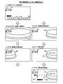
図13は、大入賞口開放パターン判定テーブルT8を説明するための図である。大入賞口開放パターン判定テーブルT8は、遊技制御用マイコン81が主制御メイン処理(後述)において、特図停止図柄データ(図9)に応じて、第1大入賞口30および第2大入賞口35の開放パターンを判定するために参照されるテーブルである。図13(A)では、特図停止図柄データが「11H」、「12H」、または、「21H」のとき、第1大入賞口30および第2大入賞口35の開放パターンは「開放パターン21」と判定され、特図停止図柄データが「14H」または「15H」のとき、開放パターンは「開放パターン22」と判定され、特図停止図柄データが「13H」のとき、開放パターンは「開放パターン23」と判定されることが示されている。図13(B)には、開放パターン21、開放パターン22および開放パターン23の内容が示されている。開放パターン21では1~13、15R目において、開放回数1回、開放時間29.5秒の第1大入賞口30の開放(ロング開放)をおこない、14、16R目において、開放回数1回、開放時間29.5秒の第2大入賞口35の開放(ロング開放)をおこなう。開放パターン22では1~13R目において、開放回数1回、開放時間29.5秒の第1大入賞口30の開放(ロング開放)をおこない、14、16R目において、開放回数1回、開放時間0.1秒の第2大入賞口35の開放(ショート開放)をおこない、15R目において、開放回数1回、開放時間0.1秒の第1大入賞口30の開放(ショート開放)をおこなう。開放パターン23では1~13、15R目において、開放回数1回、開放時間29.5秒の第1大入賞口30の開放(ロング開放)をおこない、14R目において、開放回数1回、開放時間0.1秒の第2大入賞口35の開放(ショート開放)をおこない、16R目において、開放回数1回、開放時間29.5秒の第2大入賞口35の開放(ロング開放)をおこなう。ただし、第1大入賞口30および第2大入賞口35の開放は、予め定められた数の遊技球の入賞(規定入賞数、最大9個)があった場合、開放時間が残っていても閉鎖される。
FIG. 13 is a diagram for explaining the large winning opening opening pattern determination table T8. In the
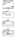
図14は、V開閉部材開放パターン判定テーブルT9を説明するための図である。V開閉部材開放パターン判定テーブルT9は、遊技制御用マイコン81が主制御メイン処理(後述)において、特図停止図柄データ(図9)に応じて、V開閉部材71の開放パターンを判定するために参照されるテーブルである。図14(A)では、特図停止図柄データが「11H」、「12H」、または、「21H」のとき、V開閉部材71の開放パターンは「開放パターン31」と判定され、特図停止図柄データが「13H」のとき、開放パターンは「開放パターン32」と判定され、特図停止図柄データが「14H」のとき、開放パターンは「開放パターン33」と判定され、特図停止図柄データが「15H」のとき、開放パターンは「開放パターン34」と判定されることが示されている。図14(B)には、開放パターン31、開放パターン32、開放パターン33、および、開放パターン34の内容が示されている。開放パターン31では2、4、6、8R目において、第1大入賞口30に1個目の入賞があったとき開放時間0.1秒のV開閉部材71のショート開放をおこなう。10、12R目において、第1大入賞口30に1個目の入賞があったとき開放時間0.1秒のV開閉部材71のショート開放をおこない、2個目の入賞があったとき開放時間最大31.5秒のV開閉部材71のロング開放をおこなう。開放パターン32では2、4、6、12R目において、第1大入賞口30に1個目の入賞があったとき開放時間0.1秒のV開閉部材71のショート開放をおこなう。8、10R目において、第1大入賞口30に1個目の入賞があったとき開放時間0.1秒のV開閉部材71のショート開放をおこない、2個目の入賞があったとき開放時間最大31.5秒のV開閉部材71のロング開放をおこなう。開放パターン33では2、6R目において、第1大入賞口30に1個目の入賞があったとき開放時間0.1秒のV開閉部材71のショート開放をおこない、2個目の入賞があったとき開放時間最大31.5秒のV開閉部材71のロング開放をおこなう。4、8、10、12R目において、第1大入賞口30に1個目の入賞があったとき開放時間0.1秒のV開閉部材71のショート開放をおこなう。開放パターン34では2、4、6、8、10、12R目において、第1大入賞口30に1個目の入賞があったとき開放時間0.1秒のV開閉部材71のショート開放をおこなう。
FIG. 14 is a diagram for explaining the V opening / closing member opening pattern determination table T9. The V opening / closing member opening pattern determination table T9 is used by the
4.大当たり等の説明
遊技機1では、大当たり抽選(特別図柄抽選)の結果としての「大当たり」と「ハズレ」がある。「大当たり」の場合には、特別図柄表示器41に「大当たり図柄」が停止表示される。「ハズレ」のときには、特別図柄表示器41に「ハズレ図柄」が停止表示される。大当たりに当選すると、停止表示された特別図柄の種類(大当たりの種類)に応じた開放パターンにて、大入賞口(第1大入賞口30および第2大入賞口35)を開放させる「大当たり遊技」が実行される。大当たり遊技は、特別遊技の一例である。大当たり遊技は、複数回のラウンド遊技(単位開放遊技)と、初回のラウンド遊技が開始される前のオープニング(OP)と、最終回のラウンド遊技が終了した後のエンディング(ED)とを含んでいる。各ラウンド遊技は、オープニングの終了、または、前のラウンド遊技の終了によって開始し、次のラウンド遊技の開始によって終了する。ラウンド遊技間の大入賞口の閉鎖の時間(インターバル時間)は、その閉鎖前の開放ラウンド遊技に含まれる。
4. Explanation of jackpots, etc. In
大当たりには複数の種別がある。大当たりの種別については、図9に示すとおりである。ここでは、大当たりの種別としては、大きく分けて「V通過予定大当たり」と「V非通過予定大当たり」の2つある。「V通過予定大当たり」は、その大当たり遊技中にV領域39への遊技球の通過が可能な開放パターン(V通過予定開放パターン)で開閉部材32、開閉部材37およびV開閉部材71を作動させる大当たりである。ここでは、特図停止図柄データが11H~14H,21Hの大当たりが「V通過予定大当たり」に該当する。図13に示す開閉部材32および開閉部材37の開放パターンと、図14に示すV開閉部材71の開放パターンとの組み合わせが、(開放パターン21:開放パターン31)、(開放パターン22:開放パターン33)、または(開放パターン23:開放パターン32)のとき、その大当たり遊技中にV領域39への遊技球の通過が可能となる。「V非通過予定大当たり」は、その大当たり遊技中にV領域39への遊技球の通過が不可能な開放パターン(V非通過予定開放パターン)で開閉部材32、開閉部材37およびV開閉部材71を作動させる大当たりである。ここでは、特図停止図柄データが17Hの大当たりが「V非通過予定大当たり」に該当する。図13に示す開閉部材32および開閉部材37の開放パターンと、図14に示すV開閉部材71の開放パターンとの組み合わせが(開放パターン22:開放パターン34)のとき、その大当たり遊技中にV領域39への遊技球の通過が不可能となる。上記のように、開閉部材32および開閉部材37の開放パターン22は、V通過予定開放パターンとV非通過予定開放パターンとを兼ねている。
There are multiple types of jackpots. The types of jackpots are as shown in FIG. Here, there are roughly two types of jackpots, "V-passing planned jackpot" and "V non-passing scheduled jackpot". The "V-passing scheduled jackpot" operates the opening / closing
「V通過予定大当たり」は、「16RV通過予定大当たり」と、「16R(実質13R)V通過予定大当たり」と、「16R(実質15R)V通過予定大当たり」と、を含んでいる。「16RV通過予定大当たり」は、実質的な総ラウンド数が16Rである。1Rから13Rまでと15Rは第1大入賞口30を1R当たり最大29.5秒にわたって開放する。14Rと16Rは第2大入賞口35を1R当たり最大29.5秒にわたって開放する(図13:開放パターン21)。10Rおよび12Rでは、V開閉部材71がロング開放され(図14:開放パターン31)、第1大入賞口30内のV領域39への通過が容易に可能である。
The "V-passing jackpot" includes "16RV-passing jackpot", "16R (substantial 13R) V-passing jackpot", and "16R (substantially 15R) V-passing jackpot". The actual total number of rounds of the "16RV passing jackpot" is 16R. From 1R to 13R and 15R, the first big winning
「16R(実質13R)V通過予定大当たり」は、総ラウンド数は16Rであるものの、実質的な総ラウンド数は13Rである。つまり、1Rから13Rまでは第1大入賞口30を1R当たり最大29.5秒にわたって開放するが、15Rでは第1大入賞口30を1R当たり0.1秒しか開放せず、また、14Rと16Rでも第2大入賞口35を1R当たり0.1秒しか開放しない(図13:開放パターン22)。従って、この「16R(実質13R)V通過予定大当たり」では14Rから16Rまでは、大入賞口の開放時間が極めて短く、賞球の見込めないラウンドとなっている。つまり、「16R(実質13R)V通過予定大当たり」は、実質13Rの大当たりとなっている。2Rおよび6Rでは、V開閉部材71がロング開放され(図14:開放パターン33)、第1大入賞口30内のV領域39への通過が容易に可能である。
Although the total number of rounds of the "16R (substantial 13R) V-passing jackpot" is 16R, the actual total number of rounds is 13R. That is, from 1R to 13R, the first big winning
「16R(実質15R)V通過予定大当たり」は、総ラウンド数は16Rであるものの、実質的な総ラウンド数は15Rである。つまり、1Rから13Rまでと15Rは第1大入賞口30を1R当たり最大29.5秒にわたって開放し、16Rでは第2大入賞口35を1R当たり最大29.5秒にわたって開放するが、14Rでは第2大入賞口35を1R当たり0.1秒しか開放しない(図13:開放パターン23)。従って、この「16R(実質15R)V通過予定大当たり」では14Rは、大入賞口の開放時間が極めて短く、賞球の見込めないラウンドとなっている。つまり、「16R(実質15R)V通過予定大当たり」は、実質15Rの大当たりとなっている。8Rおよび10Rでは、V開閉部材71がロング開放され(図14:開放パターン32)、第1大入賞口30内のV領域39への通過が容易に可能である。
Although the total number of rounds of the "16R (substantial 15R) V-passing jackpot" is 16R, the actual total number of rounds is 15R. That is, from 1R to 13R and 15R, the
「V非通過予定大当たり」は、総ラウンド数は16Rであるものの、実質的な総ラウンド数は13となる開放パターン22の「16R(実質13R)V非通過予定大当たり」である。つまり、1Rから13Rまでは第1大入賞口30を1R当たり最大29.5秒にわたって開放するが、15Rでは第1大入賞口30を1R当たり0.1秒しか開放せず、また、14Rと16Rでも第2大入賞口35を1R当たり0.1秒しか開放しない(図13:開放パターン22)。従って、この「16R(実質13R)V非通過予定大当たり」では14Rから16Rまでは、大入賞口の開放時間が極めて短く、賞球の見込めないラウンドとなっている。つまり、「16R(実質13R)V非通過予定大当たり」は実質13Rの大当たりとなっている。2R,4R,6R,8R,10Rおよび12Rでは、V開閉部材71は開放されるもののその開放はショート開放であり(図14:開放パターン34)、第1大入賞口30内のV領域39に遊技球が通過することはほぼ不可能となっている。
The "V non-passing planned jackpot" is the "16R (substantially 13R) V non-passing scheduled jackpot" of the
上記の説明から明らかなように、「16R(実質13R)V非通過予定大当たり」と「16R(実質13R)V通過予定大当たり」とは、第1大入賞口30と第2大入賞口35(開閉部材32と開閉部材37)との開放パターンが同一(開放パターン22)であり、V開閉部材71の開放パターンのみが異なっている(開放パターン34と開放パターン33)。すなわち、「16R(実質13R)V非通過予定大当たり」は、第1大入賞口30内のV領域39に遊技球が通過することはほぼ不可能になっており、当該大当たり後の遊技状態は低確時短状態(低確高ベース状態)となる。一方、「16R(実質13R)V通過予定大当たり」は、第1大入賞口30内のV領域39への遊技球の通過が容易に可能になっており、当該大当たり後の遊技状態は高確時短状態(高確高ベース状態)となる。このことから、遊技者は、「16R(実質13R)V非通過予定大当たり」と「16R(実質13R)V通過予定大当たり」とを見分けることが困難になり、当該大当たり後の遊技状態が低確時短状態(低確高ベース状態)になるか高確時短状態(高確高ベース状態)になるかが判別し難くなる。すなわち、「16R(実質13R)V通過予定大当たり」後の遊技状態は、第1大入賞口30内のV領域39に遊技球が通過した場合には、高確時短状態(高確高ベース状態)でありながら高確率になっていることが潜伏した状態(潜伏確変状態)となる。
As is clear from the above explanation, "16R (real 13R) V non-passing jackpot" and "16R (real 13R) V scheduled jackpot" are the first big winning
また、図9に示すように、第1特別図柄(特図1)の抽選における大当たりの振分率は、V通過予定大当たりが68/128(約53%)、V非通過予定大当たりが60/128(約47%)となっている。これに対して、第2特別図柄(特図2)の抽選において当選した大当たりは、全てV通過予定大当たりとなっている。すなわち、後述の電サポ制御の実行により入球可能となる第2始動口21への入賞に基づく抽選により大当たりに当選した場合には、必ずV通過予定大当たりとなる。このように遊技機1では、第1始動口20に遊技球が入賞して行われる大当たり抽選(第1特別図柄の抽選)よりも、第2始動口21に遊技球が入賞して行われる大当たり抽選(第2特別図柄の抽選)の方が、遊技者にとって有利となるように設定されている。
Further, as shown in FIG. 9, the jackpot distribution rate in the lottery of the first special symbol (special figure 1) is 68/128 (about 53%) for the V-passing jackpot and 60 / for the V-non-passing jackpot. It is 128 (about 47%). On the other hand, all the jackpots won in the lottery of the second special symbol (special figure 2) are the jackpots scheduled to pass V. That is, when a big hit is won by a lottery based on a prize in the
5.遊技状態の説明
遊技機1の遊技状態について説明する。遊技制御用マイコン81は、特別図柄表示器41に表示する特別図柄および普通図柄表示器42に表示する普通図柄に対して、それぞれ、「確率変動制御」と「変動時間短縮制御」とを実行可能である。ここでは、遊技制御用マイコン81が特別図柄表示器41の特別図柄に対して確率変動制御している状態を「高確率状態」と呼び、確率変動制御していない状態を単に「通常確率状態(非高確率状態、低確率状態)」と呼ぶ。遊技制御用マイコン81は、特別図柄の確率変動制御として、大当たりと判定される大当たり乱数値の数が通常確率状態よりも高確率状態の方が多い大当たり判定テーブル(図8(A))を用いた大当たり判定をおこなうことにより、高確率状態を実現する。従って、高確率状態は、通常確率状態よりも大当たりの確率が高くなる。つまり、遊技制御用マイコン81が特別図柄表示器41の特別図柄に対して確率変動制御を実行している場合には、確率変動制御を実行していない場合と比べて、特別図柄表示器41による特別図柄の可変表示の表示結果(停止図柄)が大当たり図柄となる確率が高くなる。
5. Description of the game state The game state of the
また、遊技制御用マイコン81が特別図柄表示器41の特別図柄に対して変動時間短縮制御している状態を「時短状態」といい、変動時間短縮制御していない状態を単に「非時短状態」という。時短状態は、特別図柄の変動時間(変動表示開始時から表示結果の導出表示時までの時間)が、非時短状態よりも短くなっている。遊技制御用マイコン81は、時短状態のときに、変動時間の短い変動パターンが選択されることが非時短状態よりも多くなるように定められた変動パターン判定テーブルT6(図10、図11)を用いた変動パターンの判定をおこなう。つまり、遊技制御用マイコン81が特別図柄表示器41の特別図柄に対して変動時間短縮制御を実行している場合には、変動時間短縮制御を実行していない場合と比べて、特別図柄の可変表示の変動時間として短い変動時間が選択されやすくなる。その結果、時短状態では、特図保留の消化のペースが速くなり、始動口への有効な入賞(特図保留として記憶され得る入賞)が発生しやすくなる。これにより、スムーズな遊技の進行のもとで大当たりを狙うことができる。なお、遊技制御用マイコン81は、特別図柄表示器41の特別図柄に対して、確率変動制御と変動時間短縮制御とを同時に実行することもあるし、片方のみ実行することもある。
Further, the state in which the
遊技制御用マイコン81は、普通図柄表示器42の普通図柄に対する確率変動制御および変動時間短縮制御を、特別図柄表示器41の特別図柄に対する変動時間短縮制御に同期して実行する。すなわち、遊技制御用マイコン81は、普通図柄に対する確率変動制御および変動時間短縮制御を、時短状態の場合は実行し、非時短状態の場合には実行しない。遊技制御用マイコン81は、普通図柄の確率変動制御として、当たりと判定される普通図柄乱数値(当たり乱数値)の数が非時短状態よりも時短状態の方が多い普通図柄当たり判定テーブルT3(図8(C))を用いて、当たり判定(普通図柄の判定)をおこなう。従って、時短状態では、普通図柄通常確率状態よりも当たり確率が高くなる。つまり、遊技制御用マイコン81が普通図柄表示器42の普通図柄に対して確率変動制御を実行している場合には、確率変動制御を実行していない場合と比べて、普通図柄表示器42による普通図柄の可変表示の表示結果(停止図柄)が当たり図柄となる確率が高くなる。時短状態では、普通図柄の変動時間が非時短状態よりも短くなっている。ここでは、普通図柄の変動時間は非時短状態では30秒であるが、時短状態では1秒である(図8(D))。さらに時短状態では、補助遊技における電チュー22の開放時間が、非時短状態よりも長くなっている(図12)。すなわち、遊技制御用マイコン81は、電チュー22に対して開放時間延長制御を実行している。加えて、時短状態では、補助遊技における電チュー22の開放回数が非時短状態よりも多くなっている(図12)。すなわち、遊技制御用マイコン81は、電チュー22に対して開放回数増加制御を実行している。遊技制御用マイコン81が、普通図柄表示器42の普通図柄に対する確率変動制御と変動時間短縮制御、および、電チュー22に対する開放時間延長制御と開放回数増加制御とを実行している状況下では、これらの制御を実行していない場合と比べて、電チュー22が頻繁に開放され、第2始動口21へ遊技球が頻繁に入賞することとなる。その結果、発射球数に対する賞球数の割合であるベースが高くなる。従って、これらの制御が実行されている状態を「高ベース状態」といい、実行されていない状態を「低ベース状態」という。高ベース状態では、手持ちの遊技球を大きく減らすことなく大当たりを狙うことができる。なお、高ベース状態とは、いわゆる電サポ制御(電チュー22により第2始動口21への入賞をサポートする制御)が実行されている状態である。高ベース状態(電サポ制御状態)は、上記の全ての制御を実行するものでなくてもよい。すなわち、普通図柄表示器42の普通図柄に対する確率変動制御、普通図柄表示器42の普通図柄に対する変動時間短縮制御、電チュー22に対する開放時間延長制御、および、電チュー22に対する開放回数増加制御のうち一つ以上の制御を実行することによって、その制御が実行されていないときよりも電チュー22が開放され易くなっていればよい。また、高ベース状態(電サポ制御状態)は、時短状態に付随せずに独立して制御されるようにしてもよい。
The
遊技機1では、V通過予定大当たりへの当選による大当たり遊技後の遊技状態は、その大当たり遊技中にV領域39への通過がなされていれば、高確率状態かつ時短状態かつ高ベース状態である。この遊技状態を特に、「高確高ベース状態」、または、「高確時短状態」という。高確高ベース状態は、所定回数(ここでは160回)の特別図柄の可変表示が実行されるか、または、大当たりに当選してその大当たり遊技が実行されることにより終了する。また、V非通過予定大当たりへの当選による大当たり遊技後の遊技状態は、その大当たり遊技中にV領域39の通過がなされていなければ(なされることはほぼない)、通常確率状態(非高確率状態すなわち低確率の状態)かつ時短状態かつ高ベース状態である。この遊技状態を特に、「低確高ベース状態」、「低確時短状態」という。低確高ベース状態は、所定回数(ここでは100回)の特別図柄の可変表示が実行されるか、または、大当たりに当選してその大当たり遊技が実行されることにより終了する。遊技機1を初めて遊技する場合において電源投入後の遊技状態は、通常確率状態かつ非時短状態かつ低ベース状態(非電サポ制御状態)である。この遊技状態を特に、「低確低ベース状態」という。低確低ベース状態を「通常遊技状態」、または、「低確非時短状態(単に、非時短状態とも呼ぶ)」、と称することもある。また、特別遊技(大当たり遊技)の実行中の状態を「特別遊技状態(大当たり遊技状態)」と称することとする。さらに、高確率状態および高ベース状態のうち少なくとも一方の状態に制御されている状態を、「特定遊技状態」という。
In the
高確高ベース状態や低確高ベース状態といった高ベース状態では、右打ちによって右遊技領域3B(図1)へ遊技球を進入させた方が有利に遊技を進行させることができる。電サポ制御によって、低ベース状態と比べて電チュー22が開放されやすくなっており、第1始動口20への入賞よりも第2始動口21への入賞の方が容易となっているためである。このことから、高ベース状態では、普通図柄抽選の契機となるゲート28へ遊技球を通過させつつ、第2始動口21へ遊技球を入賞させるべく右打ちをおこなう。これにより左打ちをするよりも、多数の始動入賞(始動口への入賞)を得ることができる。なお、遊技機1では、大当たり遊技中も右打ちにて遊技をおこなう。一方、低ベース状態では、左打ちによって左遊技領域3A(図1)へ遊技球を進入させた方が有利に遊技を進行させることができる。電サポ制御が実行されていないため、高ベース状態と比べて電チュー22が開放されにくくなっており、第2始動口21への入賞よりも第1始動口20への入賞の方が容易となっているためである。このことから、低ベース状態では、第1始動口20へ遊技球を入賞させるべく左打ちをおこなう。これにより右打ちするよりも、多数の始動入賞を得ることができる。
In a high base state such as a high accuracy high base state or a low accuracy high base state, it is more advantageous to allow the game ball to enter the
6.遊技制御用マイコン81の動作
図15~図34に基づいて主制御基板80(図3)に設けられた遊技制御用マイコン81の動作について説明する。遊技制御用マイコン81の動作説明にて登場するカウンタ、フラグ、ステータス、バッファ等はメインRAM84に設けられている。遊技制御用マイコン81は、当否判定手段(図23)、当否事前判定手段(図18、図19)に該当する。
6. Operation of
[主制御メイン処理]
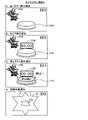
図15は、主制御メイン処理のフローチャートである。遊技制御用マイコン81は、遊技機1の電源がオンされると、メインROM83から主制御メイン処理を実行するためのプログラムを読み出す。主制御メイン処理では、遊技制御用マイコン81は、まず、初期設定をおこなう(ステップS001)。初期設定では、例えば、メインCPU82の設定、各種のフラグ、ステータスおよびカウンタなどのリセット等をおこなう。フラグの初期値は「0」つまり「OFF」であり、ステータスの初期値は「1」であり、カウンタの初期値は「0」である。なお、初期設定は、電源投入後に一度だけ実行され、それ以降は実行されない。
[Main control main processing]
FIG. 15 is a flowchart of the main control main process. When the power of the
初期設定の後、遊技制御用マイコン81は、割り込み処理の割り込みを禁止し(ステップS002)、普通図柄・特別図柄主要乱数更新処理(ステップS003)をおこなう。この普通図柄・特別図柄主要乱数更新処理では、遊技制御用マイコン81は、図7(A)で示した種々の乱数カウンタ値(大当たり乱数値、大当たり種別乱数値、リーチ乱数値、変動パターン乱数値、普通図柄乱数値)を1加算して更新する。各乱数カウンタ値は設定された上限値に達すると「0」に戻って再び加算される。なお、各乱数カウンタの初期値は「0」以外の値であってもよく、ランダムに変更されるものであってもよい。また、各乱数は、カウンタIC等からなる公知の乱数生成回路を利用して生成されるいわゆるハードウェア乱数であってもよい。
After the initial setting, the
普通図柄・特別図柄主要乱数更新処理の後、遊技制御用マイコン81は、割り込み処理の割り込みを許可する(ステップS004)。割り込み許可中は、メイン側タイマ割り込み処理(ステップS005)の実行が可能となる。メイン側タイマ割り込み処理は、所定の周期(例えば、4msec周期)でメインCPU82に繰り返し入力される割り込みパルスに基づいて実行される。すなわち、メイン側タイマ割り込み処理は、所定周期(例えば4msec周期)ごとに実行される。そして、メイン側タイマ割り込み処理が終了してから、次にメイン側タイマ割り込み処理が開始されるまでの間に、普通図柄・特別図柄主要乱数更新処理による各種カウンタ値の更新処理が繰り返し実行される。なお、割り込み禁止状態のときに、メインCPU82に割り込みパルスが入力された場合は、メイン側タイマ割り込み処理はすぐには開始されず、割り込み許可がされてから開始される。
After the normal symbol / special symbol main random number update process, the
[メイン側タイマ割り込み処理]
図16は、メイン側タイマ割り込み処理(図15:ステップS005)のフローチャートである。メイン側タイマ割り込み処理では、遊技制御用マイコン81は、まず、乱数更新処理をおこなう(ステップS101)。具体的には、遊技制御用マイコン81は、図7(A)で示した種々の乱数カウンタ値を更新する。この乱数更新処理は、上述した主制御メイン処理(図15)でおこなう普通図柄・特別図柄主要乱数更新処理と同じである。すなわち、各種乱数カウンタ値の更新処理は、メイン側タイマ割り込み処理の実行期間と、それ以外の期間(メイン側タイマ割り込み処理の終了後、次のメイン側タイマ割り込み処理が開始されるまでの期間)との両方でおこなわれる。
[Main timer interrupt processing]
FIG. 16 is a flowchart of the main timer interrupt process (FIG. 15: step S005). In the main-side timer interrupt processing, the
乱数更新処理の後、遊技制御用マイコン81は、入力処理をおこなう(ステップS102)。入力処理では、遊技制御用マイコン81は、遊技機1に取り付けられている各種センサが検出した検出信号を読み込み、入賞口の種類に応じた賞球を払い出すための払い出しデータをメインRAM84の出力バッファにセットする。各種センサとは、例えば、第1始動口センサ20a、第2始動口センサ21a、第1大入賞口センサ30a、第2大入賞口センサ35a、普通入賞口センサ27a(図3)である。
After the random number update process, the
入力処理の後、遊技制御用マイコン81は、始動口センサ検出処理(ステップS103)、普通動作処理(ステップS104)、特別動作処理(ステップS105)、V領域センサ検出処理(ステップS106)、保留球数処理(ステップS107)を順に実行する。これらの処理の詳細については後述する。保留球数処理の後、遊技制御用マイコン81は、出力処理をおこなう(ステップS108)。出力処理では、遊技制御用マイコン81は、上述の各処理においてメインRAM84のコマンドセット領域84aにセットしたコマンド等をサブ制御基板90に出力する。出力処理の後、遊技制御用マイコン81は、その他の処理をおこなう(ステップS109)。その他の処理では、例えば、後述の特図2保留球数に基づいて第2特図保留表示器43bをその数を示す表示態様に制御し、特図1保留球数に基づいて第1特図保留表示器43aをその数を示す表示態様に制御する。
After the input processing, the
[始動口センサ検出処理]
図17は、始動口センサ検出処理(図16:ステップS103)のフローチャートである。遊技制御用マイコン81は、まず、ゲート28に遊技球が通過したか否かの判定をおこなう(ステップS201)。この判定は、ゲートセンサ28aによって遊技球が検出されたか否かによっておこなわれる。ゲート28に遊技球が通過していない場合(ステップS201:NO)、処理はステップS205にスキップする。ゲート28に遊技球が通過した場合(ステップS201:YES)、遊技制御用マイコン81は、普通図柄保留球数が「4(上限値)」であるか否かの判定をおこなう(ステップS202)。普通図柄保留球数とは、普図保留の数であり、より具体的には、メインRAM84に設けられた普図保留の数をカウントするカウンタの値である。普通図柄保留球数が「4」であれば(ステップS202:YES)、処理はステップS205にスキップする。普通図柄保留球数が「3」以下の場合(ステップS202:NO)、普通図柄保留球数に「1」を加算した後(ステップS203)、普通図柄乱数取得処理をおこなう(ステップS204)。ここでは、遊技制御用マイコン81は、普通図柄乱数カウンタの値(図7:ラベル-TRND-Hの値)を取得し、取得した乱数値をメインRAM84の普図保留記憶領域86の第1~第4記憶領域うち、現在の普通図柄保留球数に応じた記憶領域に格納する。
[Starting port sensor detection process]
FIG. 17 is a flowchart of the start port sensor detection process (FIG. 16: step S103). The
ステップS205では、遊技制御用マイコン81は、第2始動口21に遊技球が入賞したか否かの判定をおこなう。この判定は、第2始動口センサ21aによって遊技球が検出されたか否かによっておこなわれる。第2始動口21に遊技球が入賞していない場合(ステップS205:NO)、処理はステップS210にスキップする。遊技球が入賞した場合(ステップS205:YES)、遊技制御用マイコン81は、特図2保留球数が「4(上限値)」であるか否かの判定をおこなう(ステップS206)。特図2保留球数とは、第2特図保留の数であり、より具体的には、メインRAM84に設けられた第2特図保留の数をカウントするカウンタの値である。特図2保留球数が「4」であれば(ステップS206:YES)、処理はステップS210にスキップする。特図2保留球数が「3」以下の場合(ステップS206:NO)、特図2保留球数に「1」を加算した後(ステップS207)、特図2関係乱数取得処理をおこなう(ステップS208)。ここでは、大当たり乱数カウンタの値(図7:ラベル-TRND-Aの値)、大当たり種別乱数カウンタの値(図7:ラベル-TRND-ASの値)、リーチ乱数カウンタの値(図7:ラベル-TRND-RCの値)、変動パターン乱数カウンタの値(図7:ラベル-TRND-T1の値)を取得する。遊技制御用マイコン81は、取得した乱数値群を第2特図保留記憶領域85bの第1~第4記憶領域うち、現在の特図2保留球数に応じた記憶領域に格納する。遊技制御用マイコン81は、後述の特図2事前判定処理(図18)のために、取得した乱数値群を第2特図保留記憶領域85bとは異なるバッファ(事前判定用バッファ)にも一時的に記憶(保持)させる。特図2関係乱数取得処理の後、遊技制御用マイコン81は、特図2事前判定処理をおこなう(ステップS209)。特図2事前判定処理の詳細については後述する。
In step S205, the
ステップS210では、遊技制御用マイコン81は、第1始動口20に遊技球が入賞したか否かの判定をおこなう。この判定は、第1始動口センサ20aによって遊技球が検出されたか否かによっておこなわれる。第1始動口20に遊技球が入賞していない場合(ステップS210:NO)、本処理を終了する。第1始動口20に遊技球が入賞した場合(ステップS210:YES)、遊技制御用マイコン81は、特図1保留球数が「4(上限値)」であるか否かの判定をおこなう(ステップS211)。特図1保留球数とは、第1特図保留の数であり、より具体的には、メインRAM84に設けられた第1特図保留の数をカウントするカウンタの値である。特図1保留球数が「4」であれば(ステップS211:YES)、本処理を終了する。特図1保留球数が「3」以下の場合(ステップS211:NO)、特図1保留球数に「1」を加算した後(ステップS212)、特図1関係乱数取得処理をおこなう(ステップS213)。ここでは、上述の特図2関係乱数取得処理(ステップS208)と同様に、大当たり乱数カウンタの値、大当たり種別乱数カウンタの値、リーチ乱数カウンタの値、変動パターン乱数カウンタの値を取得する。遊技制御用マイコン81は、取得した乱数値群を第1特図保留記憶領域85aの第1~第4記憶領域うち、現在の特図1保留球数に応じた記憶領域に格納する。遊技制御用マイコン81は、後述の特図1事前判定処理(図19)のために、取得した乱数値群を第1特図保留記憶領域85aとは異なるバッファ(事前判定用バッファ)にも一時的に記憶(保持)させる。特図1関係乱数取得処理の後、遊技制御用マイコン81は、特図1事前判定処理をおこなう(ステップS214)。特図1事前判定処理の詳細については後述する。
In step S210, the
[特図2事前判定処理]
図18は、特図2事前判定処理(図17:ステップS209)のフローチャートである。遊技制御用マイコン81は、まず、確変フラグがONであるか否かの判定をおこなう(ステップS301)。確変フラグがOFFの場合(ステップS301:NO)、本処理を終える。すなわち、確変フラグがOFFの場合には、事前判定はおこなわれない。一方、確変フラグがONの場合、遊技制御用マイコン81は、大当たり判定テーブルT1(図8)のうちの高確率状態用テーブルを参照して大当たり事前判定をおこなう(ステップS302)。具体的には、遊技制御用マイコン81は、まず、特図2関係乱数取得処理(図17:ステップS208)によって事前判定用バッファに一時的に記憶されている判定値としての大当たり乱数値を取得する。次に、遊技制御用マイコン81は、参照する大当たり判定テーブルT1(図8)と大当たり乱数値とを用いて大当たりか否かの事前判定をおこなう。ここでは、高確率状態(確変フラグがON)であるため、遊技制御用マイコン81は、大当たり判定テーブルT1のうち、高確率状態用のテーブル(大当たり判定値が「0」~「649」)を参照して大当たりか否かを事前判定する。すなわち、大当たり乱数値が「0」~「649」のとき「大当たり」と事前判定し、それ以外の値のとき「ハズレ」と事前判定する。なお、本実施形態では、後述する大当たり判定処理(図23)で用いられる大当たり判定テーブルT1を用いて事前判定をおこなっているが、他の実施形態として、大当たり判定テーブルT1とは異なる事前判定用の大当たり判定テーブルを用いて事前判定をおこなってもよい。
[Special Figure 2 Pre-judgment processing]
FIG. 18 is a flowchart of the special figure 2 pre-determination process (FIG. 17: step S209). The
大当たり事前判定の結果が「ハズレ」の場合(ステップS304:NO)、処理はステップS306にスキップする。一方、大当たり事前判定の結果が「大当たり」の場合(ステップS304:YES)、遊技制御用マイコン81は、大当たり種別事前判定をおこなう(ステップS305)。大当たり種別事前判定では、遊技制御用マイコン81は、まず、特図2関係乱数取得処理(図17:ステップS208)によって事前判定用バッファに一時的に記憶されている判定値としての大当たり種別乱数値を取得する。次に、遊技制御用マイコン81は、取得した大当たり種別乱数値と大当たり種別判定テーブルT5(図9)に基づいて、大当たり種別の事前判定をおこなう。ここでは、大当たり種別乱数値が「0」~「127」のいずれであっても「16RV通過予定大当たり」と事前判定する。なお、本実施形態では、後述する大当たり判定処理(図23)で用いられる大当たり種別判定テーブルT5を用いて事前判定をおこなっているが、他の実施形態として、大当たり種別判定テーブルT5とは異なる事前判定用の大当たり種別判定テーブルを用いて事前判定をおこなってもよい。
If the result of the jackpot pre-determination is "missing" (step S304: NO), the process skips to step S306. On the other hand, when the result of the jackpot pre-determination is "big hit" (step S304: YES), the
ステップS306では、遊技制御用マイコン81は、変動パターン事前判定をおこなう。具体的には、遊技制御用マイコン81は、まず、特図2関係乱数取得処理(図17:ステップS208)によって事前判定用バッファに一時的に記憶されている判定値としての変動パターン乱数値、および、リーチ乱数値を取得する。次に、ここでは、時短状態(時短フラグがON)であるため、遊技制御用マイコン81は、時短状態用の変動パターン判定テーブルT6(図11)を参照し、ステップS304の大当たり事前判定結果、リーチ乱数値から得られるリーチの有無事前判定結果、および、変動パターン乱数値から変動パターンを特定する。なお、図11の変動パターン判定テーブルT6では、保留球数の違いによって選択される変動パターンが異なる場合がある。ここでは、保留球数の違いによって選択される可能性のあるすべての変動パターンが選択されるものとする。例えば、大当たり事前判定結果、および、リーチ有無事前判定結果から、リーチ有りハズレが事前判定され、変動パターン乱数値が「60」の場合、遊技制御用マイコン81は、保留球数が「1~2」であれば選択される変動パターン「P64」と、保留球数が「3~4」であれば選択される変動パターン「P68」の2つを選択する。なお、本実施形態では、後述する変動パターン選択処理(図24、図25)で用いられる変動パターン判定テーブルT6を用いて事前判定をおこなっているが、他の実施形態として、変動パターン判定テーブルT6とは異なる事前判定用の変動パターン判定テーブルを用いて事前判定をおこなってもよい。
In step S306, the
ステップS307では、遊技制御用マイコン81は、事前判定コマンドの作成をおこなう。事前判定コマンドには、大当たり事前判定結果、(当たりの場合には大当たり種別事前判定結果)、および、変動パターン事前判定結果が含まれる。遊技制御用マイコン81は、作成した事前判定コマンドをメインRAM84のコマンドセット領域84aにセットして(ステップS308)、本処理を終える。
In step S307, the
[特図1事前判定処理]
図19は、特図1事前判定処理(図17:ステップS214)のフローチャートである。遊技制御用マイコン81は、まず、確変フラグがONであるか否かの判定をおこなう(ステップS401)。上述の特図2事前判定処理とは反対に、確変フラグがONの場合(ステップS401:YES)、本処理を終える。すなわち、確変フラグがONの場合には、事前判定はおこなわれない。一方、確変フラグがOFFの場合(ステップS401:NO)、遊技制御用マイコン81は、大当たり判定テーブルT1(図8)のうちの通常確率状態用のテーブルを参照して大当たり事前判定をおこなう(ステップS402)。具体的には、遊技制御用マイコン81は、まず、特図1関係乱数取得処理(図17:ステップS213)によって事前判定用バッファに一時的に記憶されている判定値としての大当たり乱数値を取得する。次に、ここでは、通常確率状態(確変フラグがOFF)であるため、遊技制御用マイコン81は、大当たり判定テーブルT1のうち、通常確率状態用のテーブル(大当たり判定値が「0」~「164」)に基づいて大当たりか否かを事前判定する。すなわち、大当たり乱数値が「0」~「164」のとき「大当たり」と事前判定し、それ以外の値のとき「ハズレ」と事前判定する。なお、大当たり事前判定は、大当たり判定テーブルT1とは異なる事前判定用の大当たり判定テーブルを用いてもよい。以降、ステップS404~S408の処理は、上述の特図2事前判定処理(図18)のステップS304~S308と同様であるため説明を省略する。
[Special Figure 1 Pre-judgment processing]
FIG. 19 is a flowchart of the special figure 1 pre-determination process (FIG. 17: step S214). The
[普通動作処理]
図20は、普通動作処理(図16:ステップS104)のフローチャートである。遊技制御用マイコン81は、まず、電チュー22が作動中か否かの判定をおこなう(ステップS501)。電チュー22が作動中の場合(ステップS501:YES)、処理はステップS520に移行する。電チュー22が作動中ではない場合(ステップS501:NO)、遊技制御用マイコン81は、普通図柄の変動中か否かの判定をおこなう(ステップS502)。普通図柄の変動中の場合(ステップS502:YES)、処理はステップS508にスキップする。普通図柄の変動中ではない場合(ステップS502:NO)、遊技制御用マイコン81は、普通図柄の保留球数が「0」か否かの判定をおこなう(ステップS503)。保留球数が「0」の場合(ステップS503:YES)、本処理を終了する。保留球数が1以上ある場合(ステップS503:NO)、普通図柄保留球数を1ディクリメントする(ステップS504)。従って、普通図柄の保留球数が「0」の状態でゲート28を遊技球が通過した場合、始動口センサ検出処理(図17)のステップS203において、一旦、普通図柄の保留球数が「1」になり、その後、本ステップS504において保留が消化され即座に普通図柄の保留球数が「0」になる。これは、特別図柄の保留球数についても同様である。すなわち、始動口センサ検出処理(図17)のステップS207およびステップS212において、一旦、特別図柄の保留数が「1」になり、その後、後述の特別図柄待機処理(図22)におけるステップS1404およびステップS1410において保留が消化され特別図柄の保留球数が「0」になる。次に、遊技制御用マイコン81は、普通図柄当たり判定テーブルT3(図8(C))を参照して当たり判定をおこなう(ステップS505)。具体的には、遊技制御用マイコン81は、まず、普図保留記憶領域86の第1記憶領域(普図保留の1個目に対応)に記憶されている判定値としての普通図柄乱数値(当たり乱数値)を読み出す。そして、普通図柄乱数値と、遊技状態(時短状態か否か)と、普通図柄当たり判定テーブルT3とを用いて当たりか否かを判定する。例えば、非時短状態において、普通図柄乱数値が「0」~「2」の場合には、「当たり」と判定され、普通図柄乱数値がそれ以外の場合には、「ハズレ」と判定される(図8(C)参照)。
[Normal operation processing]
FIG. 20 is a flowchart of a normal operation process (FIG. 16: step S104). The
次に、遊技制御用マイコン81は、普通図柄変動パターン判定テーブルT4(図8(D))を参照して変動パターンの選択をおこなう(ステップS506)。具体的には、遊技制御用マイコン81は、まず、遊技状態(時短状態か否か)の判定をおこない、遊技状態の判定結果と、普通図柄変動パターン判定テーブルT4とを用いて、普通図柄変動パターンとしての普通図柄の変動時間を選択する。ここでは、非時短状態のとき、普通図柄の変動時間は「30秒」と判定され、時短状態のとき、普通図柄の変動時間が「1秒」と判定される(図8(D)参照)。遊技制御用マイコン81は、選択した普通図柄変動パターンをセットすることで、普通図柄の変動表示を開始させる(ステップS507)。
Next, the
ステップS508では、遊技制御用マイコン81は、普通図柄の変動時間が経過して終了したか否かの判定をおこなう。普通図柄の変動時間とは、ステップS506で選択された変動時間である(図8(D)参照)。変動時間が終了していない場合(ステップS508:NO)、遊技制御用マイコン81は、本処理を終える。すなわち、普通図柄の変動表示が継続される。一方、変動時間が終了している場合(ステップS508:YES)、遊技制御用マイコン81は、変動表示を停止させ(ステップS509)、上述の当たり判定(ステップS505)において「ハズレ」の場合には(ステップS510:NO)、本処理を終える。一方、上述の当たり判定で「当たり」の場合には(ステップS510:YES)、遊技制御用マイコン81は、電チュー開放パターンのセットをおこなう(ステップS511)。電チュー22の開放パターンは、電チュー開放パターン判定テーブルT7(図12(A))を参照して選択される。具体的には、遊技制御用マイコン81は、遊技状態(時短状態か否か)の判定をおこない、遊技状態の判定結果と、電チュー開放パターン判定テーブルT7とを用いて電チュー22の開放パターンを選択する。ここでは、非時短状態のとき、「開放パターン11」が選択され、時短状態のとき、「開放パターン12」が選択される。開放パターンの選択後、遊技制御用マイコン81は、選択した開放パターンに従うように電チュー作動を開始させ(ステップS512)、本処理を終える。
In step S508, the
上述のステップS501において、電チュー22が作動中の場合(ステップS501:YES)、遊技制御用マイコン81は、電チュー22の閉鎖条件が成立しているか否かの判定をおこなう(ステップS520)。ここでの閉鎖条件は、電チュー22への入賞個数が規定の最大入賞個数(例えば6個)に達したこと、または、電チュー22の作動時間が経過して電チュー22を閉鎖させる時間に至ったことのいずれかが満たされていることである。電チュー22の作動時間とは、ステップS511で選択された開放パターンに対応する作動時間である。電チュー22の閉鎖条件が成立していない場合(ステップS520:NO)、遊技制御用マイコン81は、本処理を終える。一方、電チュー22の閉鎖条件が成立している場合(ステップS520:YES)、遊技制御用マイコン81は、電チュー22を閉鎖(閉塞)してその作動を停止し(ステップS521)、本処理を終える。
In step S501 described above, when the
[特別動作処理]
図21は、特別動作処理(図16:ステップS105)のフローチャートである。ここでは、特別図柄表示器41および大入賞装置(第1大入賞装置31および第2大入賞装置36)に関する処理を4つの段階に分け、各段階をそれぞれ「特別動作ステータス」の「1」、「2」、「3」、「4」と呼ぶ。遊技制御用マイコン81は、「特別動作ステータス」が「1」のとき(ステップS1301:YES)、特別図柄待機処理をおこなう(ステップS1302)。特別図柄待機処理では、大当たり判定や変動パターン選択等が実行される。「特別動作ステータス」が「2」のときには(ステップS1301:NO、ステップS1303:YES)、特別図柄変動中処理をおこなう(ステップS1304)。特別図柄変動中処理では、変動時間経過後に変動停止コマンドの出力等が実行される。「特別動作ステータス」が「3」のときには(ステップS1301、S1303:NO、ステップS1305:YES)、特別図柄確定処理をおこなう(ステップS1306)。特別図柄確定処理では、大当たり時にオープニングコマンドの出力等が実行される。「特別動作ステータス」が「4」のときには(ステップS1301、S1303、S1305:NO)、特別電動役物処理をおこなう(ステップS1308)。特別電動役物処理では、大当たり遊技が実行される。上記の各処理の詳細については後述する。なお、特別動作ステータスは、初期設定では「1」である。
[Special operation processing]
FIG. 21 is a flowchart of the special operation process (FIG. 16: step S105). Here, the processing related to the
[特別図柄待機処理]
図22は、特別図柄待機処理(図21:ステップS1302)のフローチャートである。特別図柄待機処理では、遊技制御用マイコン81は、まず、特図2保留球数が「0」であるか否かの判定をおこなう(ステップS1401)。特図2保留球数が「0」である場合(ステップS1401:YES)、すなわち、第2特図保留記憶領域85bに、第2始動口21への入賞に起因して取得した乱数値群の記憶がない場合には、処理はステップS1407に移行する。特図2保留球数が「1」以上である場合(ステップS1401:NO)、遊技制御用マイコン81は、大当たり判定処理(ステップS1402)、および、変動パターン選択処理(ステップS1403)を実行する。これらの処理の詳細については後述する。変動パターン選択処理の後、特図2保留球数を1つディクリメントする(ステップS1404)。次に、遊技制御用マイコン81は、第2特図保留記憶領域85bの第1~第4記憶領域に格納されている保留情報(各種乱数値)の格納場所を現在の位置から読み出される側に1つシフトするとともに、第2特図保留記憶領域85bにおいて読み出される側から最も遠い場所に格納されている保留情報をクリアする(ステップS1405)。例えば、第1~第3記憶領域に保留情報が格納されている場合には、第3記憶領域に格納されている保留情報をクリアし、第1~第4記憶領域に保留情報が格納されている場合には、第4記憶領域に格納されている保留情報をクリアする。上記ステップによって、第2特図保留が保留された順に消化される。この場合、画像表示装置7の表示画面7aでは、第2特図保留記憶領域85bの第1記憶領域に対応する保留画像9B(4つの保留画像9Bのうち、一番左端の保留画像9B)が保留消化画像表示領域側にシフトし、保留消化画像9Cとして表示される。また、第2特図保留記憶領域85bの第2~第4記憶領域に対応する保留画像9B(4つの保留画像9Bのうち、左から2、3、4番目の保留画像9B)がそれぞれ左側に1つシフトする(図1)。これにより、遊技者は、第2特図保留が1つ消化されたことを認識することができる。次に、遊技制御用マイコン81は、特図2変動開始処理をおこなう(ステップS1406)。特図2変動開始処理では、変動開始コマンドをメインRAM84のコマンドセット領域84aにセットし、第2特別図柄の変動表示を開始させるとともに、変動時間タイマのセットをおこなう。変動時間タイマには、変動パターン選択処理で選択された変動パターンに応じて決定される変動時間がセットされる。また、遊技制御用マイコン81は、特別動作ステータスを「2」にセットする。なお、特図2変動開始処理でセットされる変動開始コマンド(特図2変動開始コマンド)には、大当たり判定処理(ステップS1402)でセットされた特図停止図柄データに関する情報や変動パターン選択処理(ステップS1403)でセットされた変動パターンに関する情報(変動時間に関する情報を含む)が含まれている。
[Special symbol standby processing]
FIG. 22 is a flowchart of the special symbol standby process (FIG. 21: step S1302). In the special symbol standby process, the
ステップS1401において、特図2保留球数が「0」の場合(ステップS1401:YES)、遊技制御用マイコン81は、特図1保留球数が「0」であるか否かの判定をおこなう(ステップS1407)。特図1保留球数が「0」である場合(ステップS1407:YES)、すなわち、第1特図保留記憶領域85aに、第1始動口20への入賞に起因して取得した乱数値群の記憶がない場合には、処理はステップS1413に移行する。特図1保留球数が「1」以上である場合(ステップS1407:NO)、遊技制御用マイコン81は、大当たり判定処理(ステップS1408)、および、変動パターン選択処理(ステップS1409)を実行する。これらの処理の詳細については後述する。変動パターン選択処理の後、特図1保留球数を1つディクリメントする(ステップS1410)。次に、遊技制御用マイコン81は、第1特図保留記憶領域85aの第1~第4記憶領域に格納されている各種乱数値の格納場所を現在の位置から読み出される側に1つシフトするとともに、第1特図保留記憶領域85aにおいて読み出される側から最も遠い場所に格納されている保留情報をクリアする(ステップS1411)。上記ステップによって、第1特図保留が保留された順に消化される。この場合、画像表示装置7の表示画面7aでは、第1特図保留記憶領域85aの第1記憶領域に対応する保留画像9A(4つの保留画像9Aのうち、一番右端の保留画像9A)が保留消化画像表示領域側にシフトし、保留消化画像9Cとして表示される。また、第1特図保留記憶領域85aの第2~第4記憶領域に対応する保留画像9A(4つの保留画像9Aのうち、左から2、3、4番目の保留画像9A)がそれぞれ右側に1つシフトする(図1)。これにより、遊技者は、第1特図保留が1つ消化されたことを認識することができる。次に、遊技制御用マイコン81は、特図1変動開始処理をおこなう(ステップS1412)。特図1変動開始処理では、変動開始コマンドをメインRAM84のコマンドセット領域84aにセットし、第1特別図柄の変動表示を開始させるとともに、変動時間タイマのセットをおこなう。変動時間タイマには、変動パターン選択処理で選択された変動パターンに応じて決定される変動時間がセットされる。また、遊技制御用マイコン81は、特別動作ステータスを「2」にセットする(ステップS1406)。なお、特図1変動開始処理でセットされる変動開始コマンド(特図1変動開始コマンド)には、大当たり判定処理(ステップS1408)でセットされた特図停止図柄データに関する情報や変動パターン選択処理(ステップS1409)でセットされた変動パターンに関する情報(変動時間に関する情報を含む)が含まれている。
In step S1401, when the number of reserved balls in special figure 2 is "0" (step S1401: YES), the
ステップS1407において、特図1保留球数が「0」の場合(ステップS1407:YES)、遊技制御用マイコン81は、画像表示装置7の表示画面7aが待機画面か否かの判定をおこなう(ステップS1413)。待機画面とは、客待ち用のデモ画面のことである。遊技制御用マイコン81は、例えば、客待ち用のデモ画面表示フラグのON/OFFによって判定してもよい。待機画面である場合(ステップS1413:YES)、本処理を終了する。待機画面でない場合(ステップS1413:NO)、遊技制御用マイコン81は、所定の待機時間の経過をまって、待機場面を表示させるための客待ち待機コマンドをメインRAM84のコマンドセット領域84aにセットし(ステップS1414)、本処理を終える。上記のように、本実施形態の特別図柄待機処理によれば、第1特図保留に基づく特別図柄の変動表示は、第2特図保留が「0」の場合に限って実行される。すなわち、第2特図保留の消化は、第1特図保留の消化に優先して実行される。また、本実施形態の大当たり種別判定テーブルT5によれば、第2特図保留に基づく抽選の方が、第1特図保留に基づく抽選よりも遊技者にとって利益の大きい大当たり(V通過予定大当たり)に当選しやすくなっている。
In step S1407, when the number of reserved balls in Special Figure 1 is "0" (step S1407: YES), the
[大当たり判定処理]
図23は、大当たり判定処理(図22:ステップS1402、S1408)のフローチャートである。特図2の大当たり判定処理(ステップS1402)と特図1の大当たり判定処理(ステップS1408)は処理の流れが同様であるため、まとめて説明する。大当たり判定処理では、まず、遊技制御用マイコン81は、確変フラグがONであるか否かの判定をおこなう(ステップS1501)。確変フラグがONの場合(ステップS1501:YES)、大当たり判定テーブルT1(図8)のうちの高確率状態用テーブルを参照して大当たり判定をおこなう(ステップS1502)。具体的には、遊技制御用マイコン81は、まず、判定値としての大当たり乱数値の読み出しをおこなう。例えば、特図2の大当たり判定処理では、第2特図保留記憶領域85bの第1記憶領域(第2特図保留の1個目に対応)に記憶されている大当たり乱数値を読み出す。特図1の大当たり判定処理では、第1特図保留記憶領域85aの第1記憶領域(第1特図保留の1個目に対応)に記憶されている大当たり乱数値を読み出す。次に、遊技制御用マイコン81は、参照する大当たり判定テーブルT1と大当たり乱数値とを用いて大当たりか否かを判定する。ここでは、高確率状態(確変フラグがON)であるため、大当たり判定テーブルT1のうち、高確率状態用のテーブル(大当たり判定値が「0」~「649」)に基づいて大当たりか否かを判定する。
[Big hit judgment process]
FIG. 23 is a flowchart of the jackpot determination process (FIG. 22: steps S1402 and S1408). Since the processing flow of the jackpot determination process (step S1402) of the special figure 2 and the jackpot determination process (step S1408) of the special figure 1 are the same, they will be described together. In the jackpot determination process, first, the
ステップS1501において、確変フラグがOFFの場合(ステップS1501:NO)、遊技制御用マイコン81は、大当たり判定テーブルT1(図8)のうちの通常確率状態用のテーブルを参照して大当たり判定をおこなう(ステップS1504)。具体的には、遊技制御用マイコン81は、まず、ステップS1502と同様の方法によって大当たり乱数値の読み出しをおこなう。次に、ここでは、通常確率状態(確変フラグがOFF)であるため、大当たり判定テーブルT1のうち、通常確率状態用のテーブル(大当たり判定値が「0」~「164」)に基づいて大当たりか否かを判定する。
In step S1501, when the probability change flag is OFF (step S1501: NO), the
大当たり判定の結果が「大当たり」の場合(ステップS1503、S1505:YES)、遊技制御用マイコン81は、大当たりフラグをONにするとともに(ステップS1506)、大当たり種別の判定をおこなう(ステップS1507)。具体的には、遊技制御用マイコン81は、まず、判定値としての大当たり種別乱数値の読み出しをおこなう。例えば、特図2の大当たり判定処理では、第2特図保留記憶領域85bの第1記憶領域に記憶されている大当たり種別乱数値を読み出す。特図1の大当たり判定処理では、第1特図保留記憶領域85aの第1記憶領域に記憶されている大当たり種別乱数値を読み出す。次に、遊技制御用マイコン81は、読み出した大当たり種別乱数値と大当たり種別判定テーブルT5(図9)に基づいて、大当たり種別の判定をおこなう。大当たり種別の判定後、特定された大当たり種別に応じた特図停止図柄データ(図9)をメインRAM84に設けた大当たり種別バッファにセットして(ステップS1520)、本処理を終了する。一方、ステップS1503またはステップS1505において、大当たり判定の結果が「ハズレ」の場合、ハズレ図柄に応じた特図停止図柄データ(01H)をメインRAM84に設けた大当たり種別バッファにセットして(ステップS1520)、本処理を終了する。
When the result of the jackpot determination is "big hit" (steps S1503, S1505: YES), the
[変動パターン選択処理]
図24および図25は、変動パターン選択処理(図22:ステップS1403、S1409)のフローチャートである。特図2の変動パターン選択処理(ステップS1403)と特図1の変動パターン選択処理(ステップS1409)は処理の流れが同様であるため、まとめて説明する。変動パターン選択処理では、まず、遊技制御用マイコン81は、遊技状態が時短状態であるか否かの判定をおこなう(ステップS1600)。時短状態であるか否かの判定は、時短フラグがONか否かによっておこなわれる。時短状態である場合(ステップS1600:YES)、処理はステップS1612に移行する。時短状態でない場合(ステップS1600:NO)、遊技制御用マイコン81は、大当たりフラグがONか否かの判定をおこなう(ステップS1602)。大当たりフラグがOFFの場合(ステップS1602:NO)、処理はステップS1607に移行する。大当たりフラグがONの場合(ステップS1602:YES)、遊技制御用マイコン81は、大当たりが特図2か否かの判定をおこなう(ステップS1603)。大当たりが特図2の場合(ステップS1603:YES)、大当たり種別が必ずV通過予定大当たりとなるため、処理はステップS1605にスキップする。大当たりが特図1の場合(ステップS1603:NO)、遊技制御用マイコン81は、大当たり種別がV通過予定大当たりか否かの判定をおこなう(ステップS1604)、大当たり種別の判定は、メインRAM84にセットされている特図停止図柄データに基づいておこなわれる。
[Variation pattern selection process]
24 and 25 are flowcharts of the variation pattern selection process (FIG. 22: steps S1403 and S1409). Since the processing flow of the variation pattern selection process (step S1403) of the special figure 2 and the variation pattern selection process (step S1409) of the special figure 1 are the same, they will be described together. In the variation pattern selection process, first, the
大当たり種別がV通過予定大当たりの場合(ステップS1604:YES)、遊技制御用マイコン81は、変動パターン判定テーブルT6(図10)のうち、非時短状態V通過予定大当たり用のテーブルを参照して変動パターンの選択をおこなう(ステップS1605)。具体的には、遊技制御用マイコン81は、まず、判定値としての変動パターン乱数値の読み出しをおこなう。例えば、特図2の変動パターン選択処理では、第2特図保留記憶領域85bの第1記憶領域(第2特図保留の1個目に対応)に記憶されている変動パターン乱数値を読み出す。特図1の変動パターン選択処理では、第1特図保留記憶領域85aの第1記憶領域(第1特図保留の1個目に対応)に記憶されている変動パターン乱数値を読み出す。次に、遊技制御用マイコン81は、変動パターン判定テーブルT6と変動パターン乱数値とを用いて変動パターンを選択する。ここでは、非時短状態V通過予定大当たり用のテーブルとして、図10に示す非時短状態用の変動パターン判定テーブルT6のうち、V通過予定大当たりに該当する部分(特図1では変動パターンが「P1」~「P3」の部分、特図2では変動パターンが「P21」~「P23」の部分)が参照される(アドレスがセットされる)。読み出した変動パターン乱数値から、特図1では変動パターンとして「P1」~「P3」のいずれか、特図2では「P21」~「P23」のいずれかが選択される。
When the jackpot type is a jackpot scheduled to pass V (step S1604: YES), the
大当たり種別がV非通過予定大当たりの場合(ステップS1604:NO)、遊技制御用マイコン81は、変動パターン判定テーブルT6(図10)のうち、非時短状態V非通過予定大当たり用のテーブルを参照して変動パターンの選択をおこなう(ステップS1606)。ここでは、非時短状態V非通過予定大当たり用のテーブルとして、図10に示す非時短状態用の変動パターン判定テーブルT6のうち、V非通過予定大当たりに該当する部分(「P4」~「P6」の部分)が参照される。読み出した変動パターン乱数値から、変動パターンとして「P4」~「P6」のいずれかが選択される。
When the jackpot type is V non-passing scheduled jackpot (step S1604: NO), the
ステップS1602において、大当たりフラグがOFFの場合(ステップS1602:NO)、遊技制御用マイコン81は、リーチ乱数値がリーチ成立乱数値か否かの判定をおこなう(ステップS1607)。具体的には、遊技制御用マイコン81は、まず、判定値としてのリーチ乱数値の読み出しをおこなう。特図2の変動パターン選択処理では、第2特図保留記憶領域85bの第1記憶領域(第2特図保留の1個目に対応)に記憶されているリーチ乱数値を読み出す。特図1の変動パターン選択処理では、第1特図保留記憶領域85aの第1記憶領域(第1特図保留の1個目に対応)に記憶されているリーチ乱数値を読み出す。次に、遊技制御用マイコン81は、リーチ判定テーブルT2(図8(B))と、リーチ乱数値とを用いてリーチの有無を判定する。ここでは、非時短状態であるため、リーチ判定テーブルT2のうち、非時短状態用のテーブル(リーチ有り判定値(リーチ成立乱数値)が「0」~「13」の部分)に基づいてリーチの有無を判定する。
In step S1602, when the jackpot flag is OFF (step S1602: NO), the
リーチ乱数値がリーチ成立乱数値である場合(ステップS1607:YES)、すなわち、リーチ有りハズレの場合には、遊技制御用マイコン81は、変動パターン判定テーブルT6(図10)のうち、非時短状態リーチ有りハズレ用のテーブルを参照して変動パターンの選択をおこなう(ステップS1608)。ここでは、非時短状態リーチ有りハズレ用のテーブルとして、図10に示す非時短状態用の変動パターン判定テーブルT6のうち、リーチ有りハズレに該当する部分(特図1では変動パターンが「P7」~「P14」の部分、特図2では変動パターンが「P24」~「P31」の部分)が参照される。特図1では、読み出した変動パターン乱数値と、現在の特図1保留球数(1~4)から、変動パターンとして「P7」~「P14」のいずれかが選択される。特図2では、読み出した変動パターン乱数値と、現在の特図2保留球数(1~4)から、変動パターンとして「P24」~「P31」のいずれかが選択される。保留球数によって選択される変動パターンが変わるため、保留球数に応じた短縮変動の機能が働くようになっている。すなわち、特図1および特図2のいずれにおいても、保留球数が「3」~「4」であるときは、保留球数が「1」~「2」であるときに比べて変動時間の短い変動パターンがより多く選択されるようになっている。これにより、保留球数が多いときに特図保留の消化スピードを速めることができる。
When the reach random number value is the reach establishment random number value (step S1607: YES), that is, in the case of loss with reach, the
リーチ乱数値がリーチ成立乱数値ではない場合(ステップS1607:NO)、すなわち、リーチ無しハズレの場合には、遊技制御用マイコン81は、変動パターン判定テーブルT6(図10)のうち、非時短状態リーチ無しハズレ用のテーブルを参照して変動パターンの選択をおこなう(ステップS1609)。ここでは、非時短状態リーチ無しハズレ用のテーブルとして、図10に示す非時短状態用の変動パターン判定テーブルT6のうち、リーチ無しハズレに該当する部分(特図1では変動パターンが「P15」~「P16」の部分、特図2では変動パターンが「P32」~「P33」の部分)が参照される。特図1では、読み出した変動パターン乱数値と、現在の特図1保留球数(1~4)から、変動パターンとして「P15」、「P16」のいずれかが選択される。特図2では、読み出した変動パターン乱数値と、現在の特図2保留球数(1~4)から、変動パターンとして「P32」、「P33」のいずれかが選択される。ここでも、保留球数によって選択される変動パターンが変わるため、保留球数に応じた短縮変動の機能が働くようになっている。
When the reach random number value is not the reach establishment random number value (step S1607: NO), that is, in the case of loss without reach, the
ステップS1600において、遊技状態が時短状態であると判定した場合には、遊技制御用マイコン81は、大当たりフラグがONか否かの判定をおこなう(図25:ステップS1612)。以後、ステップS1613~S1619の処理は、以下の点を除いては上述のステップS1603~S1609の処理と同様であるため説明を省略する。ステップS1613~S1619の処理とステップS1603~S1609の処理との違いは、ステップS1615、S1616、S1618、S1619において、参照される変動パターン判定テーブルT6の部分が既述のステップS1605、S1606、S1608、S1609と異なる。具体的には、S1605、S1606、S1608、S1609では、非時短状態用の変動パターン判定テーブルT6(図10)が参照されるのに対して、ステップS1615、S1616、S1618、S1619では、時短状態用の変動パターン判定テーブルT6(図11)が参照される。例えば、ステップS1615の場合、すなわち、大当たり種別がV通過予定大当たりの場合、図11に示す時短状態用の変動パターン判定テーブルT6のうち、V通過予定大当たりに該当する部分(特図1では変動パターンが「P41」~「P43」の部分、特図2では変動パターンが「P61」~「P63」の部分)が参照される。読み出した変動パターン乱数値から、特図1では変動パターンとして「P41」~「P43」のいずれか、特図2では「P61」~「P63」のいずれかが選択される。また、例えば、ステップS1616の場合、すなわち、大当たり種別がV非通過予定大当たりの場合、図11に示す時短状態用の変動パターン判定テーブルT6のうち、V非通過予定大当たりに該当する部分(「P44」~「P46」の部分)が参照される。読み出した変動パターン乱数値から、変動パターンとして「P44」~「P46」のいずれかが選択される。
When it is determined in step S1600 that the game state is the time saving state, the
上記のように変動パターンの選択をおこなった後、遊技制御用マイコン81は、選択した変動パターンをセットして(ステップS1630)本処理を終える。セットされた変動パターンの情報は変動開始コマンドに含められて、出力処理(図16:ステップS108)においてサブ制御基板90に送信される。これにより特別図柄の変動表示が開始される。
After selecting the variation pattern as described above, the
[特別図柄変動中処理]
図26は、特別図柄変動中処理(図21:ステップS1304)のフローチャートである。遊技制御用マイコン81は、まず、特別図柄の変動時間が経過して終了したか否かの判定をおこなう(ステップS1701)。特別図柄の変動時間とは、上述の変動パターン選択処理(図24、図25)で選択された変動パターンに応じて決定される変動時間である。変動時間が終了していない場合(ステップS1701:NO)、本処理を終える。すなわち、特別図柄待機処理(図22)のステップS1406またはS1412において開始された特別図柄の変動表示が継続される。一方、変動時間が終了している場合(ステップS1701:YES)、変動停止コマンドをセットし(ステップS1702)、特別動作ステータスを「3」にセットする(ステップS1703)。また、遊技制御用マイコン81は、変動停止にともなうその他の処理をおこなう(ステップS1704)。例えば、遊技制御用マイコン81は、特別図柄の変動表示を、セットされている特図停止図柄データに応じた図柄で停止させる処理等をおこなう。その後、遊技制御用マイコン81は、本処理を終える。
[Processing during special symbol change]
FIG. 26 is a flowchart of the special symbol changing process (FIG. 21: step S1304). First, the
[特別図柄確定処理]
図27は、特別図柄確定処理(図21:ステップS1306)のフローチャートである。遊技制御用マイコン81は、まず、遊技状態管理処理をおこなう(ステップS1801)。遊技状態管理処理とは、ST回数や時短回数を管理するための処理であり内容について後述する。遊技状態管理処理の後、大当たりフラグがONであるか否かの判定をおこなう(ステップS1802)。大当たりフラグがOFFである場合(ステップS1802:NO)、遊技制御用マイコン81は、特別動作ステータスを「1」にセットして(ステップS1808)、本処理を終了する。これにより、大当たり遊技は開始されず、再度、特別図柄待機処理(図22)に移行し、次の保留に対する大当たり判定等が実行される。
[Special symbol confirmation process]
FIG. 27 is a flowchart of the special symbol determination process (FIG. 21: step S1306). The
大当たりフラグがONの場合(ステップS1802:YES)、遊技制御用マイコン81は、当選した大当たりの種別に応じた大入賞口およびV開閉部材の開放パターンのセットをおこなう(ステップS1803)。具体的には、遊技制御用マイコン81は、大入賞口開放パターン判定テーブルT8(図13)を参照して、特図停止図柄データから大入賞口の開放パターンを決定し、決定した開放パターンをセットする。例えば、特図停止図柄データが「11H」の場合には、大入賞口の開放パターンとして「開放パターン21」がセットされる。また、遊技制御用マイコン81は、V開閉部材開放パターン判定テーブルT9(図14)を参照して、特図停止図柄データからV開閉部材71の開放パターンを決定し、決定した開放パターンをセットする。例えば、特図停止図柄データが「11H」の場合には、V開閉部材71の開放パターンとして「開放パターン31」がセットされる。大入賞口およびV開閉部材の開放パターンのセットとあわせてラウンドカウンタの値を、当選した大当たりの種類に応じたラウンド数にセットする。ラウンドカウンタとは、大当たり遊技中に実行した単位開放遊技(ラウンド遊技)の回数をカウントするものである。ここでは、ラウンドカウンタには「16」がセットされる(図13(B))。
When the jackpot flag is ON (step S1802: YES), the
開放パターンのセット後、遊技制御用マイコン81は、遊技状態リセット処理をおこなう(ステップS1804)。遊技状態リセット処理とは、確変フラグや時短フラグをリセットする(OFFに戻す)ための処理であり内容について後述する。遊技状態リセット処理の後、大当たり遊技を開始するために、大当たりのオープニングコマンドをセットし(ステップS1805)、オープニングを開始する(ステップS1806)。その後、特別動作ステータスを「4」にセットして(ステップS1807)、本処理を終える。
After setting the open pattern, the
[遊技状態管理処理]
図28は、遊技状態管理処理(図27:ステップS1801)のフローチャートである。遊技制御用マイコン81は、まず、確変フラグがONか否かの判定をおこなう(ステップS2001)。確変フラグがOFFの場合(ステップS2001:NO)、処理はステップS2005にスキップする。確変フラグがONの場合(ステップS2001:YES)、確変カウンタの値を1ディクリメントする(ステップS2002)。確変カウンタとは、高確率状態中に実行した特別図柄の変動回数をカウントするものである。ここでは、高確率状態への移行時に確変カウンタに「160」がセットされる。遊技制御用マイコン81は、確変カウンタを1ディクリメントした結果、カウンタの値が「0」になったか否かの判定をおこなう(ステップS2003)。確変カウンタの値が「0」ではない場合(ステップS2003:NO)、処理はステップS2005にスキップする。確変カウンタの値が「0」の場合(ステップS2003:YES)、確変フラグをOFFに切り替える(ステップS2004)。
[Game status management process]
FIG. 28 is a flowchart of the game state management process (FIG. 27: step S1801). The
ステップS2005では、遊技制御用マイコン81は、時短フラグがONか否かの判定をおこなう。時短フラグがOFFの場合(ステップS2005:NO)、処理はステップS2009にスキップする。時短フラグがONの場合(ステップS2005:YES)、時短カウンタの値を1ディクリメントする(ステップS2006)。時短カウンタとは、時短状態中に実行した特別図柄の変動回数をカウントするものである。ここでは、時短状態への移行時に、低確高ベース状態であれば時短カウンタに「100」がセットされ、高確高ベース状態であれば時短カウンタに「160」がセットされる。遊技制御用マイコン81は、時短カウンタを1ディクリメントした結果、カウンタの値が「0」になったか否かの判定をおこなう(ステップS2007)。時短カウンタの値が「0」ではない場合(ステップS2007:NO)、処理はステップS2009にスキップする。時短カウンタの値が「0」の場合(ステップS2007:YES)、時短フラグをOFFに切り替える(ステップS2008)。
In step S2005, the
ステップS2009では、遊技制御用マイコン81は、遊技状態指定コマンドをメインRAM84のコマンドセット領域(出力バッファ)84aにセットして、本処理を終える。遊技状態指定コマンドには、今設定した現在の遊技状態に関する情報(確変状態か否か、確変カウンタ値、時短状態か否か、時短カウンタ値など)が含まれている。
In step S2009, the
[遊技状態リセット処理]
図29は、遊技状態リセット処理(図27:ステップS1804)のフローチャートである。遊技制御用マイコン81は、まず、確変フラグがONか否かの判定をおこなう(ステップS2101)。確変フラグがOFFの場合(ステップS2101:NO)、処理はステップS2103にスキップする。確変フラグがONの場合(ステップS2101:YES)、確変フラグをOFFに切り替える(ステップS2102)。ステップS2103において、遊技制御用マイコン81は、時短フラグがONか否かの判定をおこなう。時短フラグがOFFの場合(ステップS2103:NO)、本処理を終える。時短フラグがONの場合(ステップS2103:YES)、時短フラグをOFFに切り替える(ステップS2104)。つまり、大当たり遊技の実行中は、非高確率状態かつ非時短状態となる。遊技機1では、非時短状態時は常に低ベース状態となるため、大当たり遊技の実行中は低ベース状態となる。
[Game state reset process]
FIG. 29 is a flowchart of the game state reset process (FIG. 27: step S1804). The
[特別電動役物処理]
図30は、特別電動役物処理(図21:ステップS1308)のフローチャートである。遊技制御用マイコン81は、まず、大当たり終了フラグがONか否かの判定をおこなう(ステップS2200)。「大当たり終了フラグ」とは、実行中の大当たり遊技において、開放パターンに基づく大入賞装置(第1大入賞装置31および第2大入賞装置36)の開放がすべて終了したことを示すフラグである。大当たり終了フラグがONの場合(ステップS2200:YES)、処理はステップS2230に移行する。大当たり終了フラグがOFFの場合(ステップS2200:NO)、V開閉部材71を作動させるためのV開閉部材動作処理をおこなう(ステップS2201)。本実施形態のV開閉部材71は、第1大入賞口30に所定個数の遊技球が入賞した時に作動するように構成されており、V開閉部材動作処理では、V開閉部材開放パターンT9に応じて所定番目の遊技球の入賞時にV開閉部材71を所定期間開放させる。V開閉部材動作処理の詳細については後述する。V開閉部材動作処理の後、遊技制御用マイコン81は、大入賞口(第1大入賞口30および第2大入賞口35)が開放中か否かの判定をおこなう(ステップS2202)。開放中の場合(ステップS2202:YES)、処理はステップS2210に移行する。
[Special electric accessory processing]
FIG. 30 is a flowchart of the special electric accessory processing (FIG. 21: step S1308). The
大入賞口が開放中ではない場合(ステップS2202:NO)、遊技制御用マイコン81は、大入賞口を開放する時間(タイミング)か否かの判定をおこなう(ステップS2203)。大入賞口を開放する時間には、例えば、大当たりのオープニングの時間が経過して初回のラウンド遊技における開放開始の時期に至ったときや、開放後に一時的に閉鎖した大入賞口を再び開放させるまでのインターバル時間(閉鎖時間)が経過して、再度の開放開始の時期に至ったときが含まれる。大入賞口を開放する時間ではない場合(ステップS2203:NO)、処理はステップS2220に移行する。
When the big winning opening is not open (step S2202: NO), the
大入賞口を開放する時間(タイミング)である場合(ステップS2203:YES)、遊技制御用マイコン81は、大入賞口開放処理をおこなう(ステップS2207)。具体的には、遊技制御用マイコン81は、大当たりの種類に応じた開放パターン(図13)に従って大入賞口(第1大入賞口30または第2大入賞口35)を開放させる。大入賞口開放処理の後、遊技制御用マイコン81は、ラウンド指定コマンドのセットをおこなう(ステップS2208)。ラウンド指定コマンドには、実行中の大当たり遊技のラウンド数に関する情報が含まれており、遊技制御用マイコン81は、ラウンド指定コマンドをメインRAM84の出力バッファにセットする。なお、本実施形態では、1回のラウンド遊技中に複数回の大入賞口の開放がなされることがない。しかし、他の実施形態として、1回のラウンド遊技中に複数回の大入賞口の開放がなされる場合には、遊技制御用マイコン81は、大入賞口の開放が1回のラウンド中での初めての開放か否かを判定し、初めての開放の場合のみ、ラウンド指定コマンドをセットするようにしてもよい。ラウンド指定コマンドをセットした後、本処理を終える。
When it is time (timing) to open the big winning opening (step S2203: YES), the
上述のステップS2202において、大入賞口の開放中の場合(ステップS2202:YES)、遊技制御用マイコン81は、大入賞口の閉鎖条件が成立しているか否かの判定をおこなう(ステップS2210)。ここでの閉鎖条件は、そのラウンド遊技における大入賞口への入賞個数が規定の最大入賞個数(例えば、1ラウンドあたり9個)に達したこと、または、大入賞口を閉鎖させる時間に至ったこと(すなわち、大入賞口を開放してから所定の開放時間(図13)が経過したこと)のいずれかが満たされていることである。そして、大入賞口の閉鎖条件が成立していなければ(ステップS2210:NO)、遊技制御用マイコン81は、本処理を終える。一方、大入賞口の閉鎖条件が成立している場合には(ステップS2210:YES)、遊技制御用マイコン81は、大入賞口を閉鎖(閉塞)する(ステップS2211)。
In step S2202 described above, when the large winning opening is open (step S2202: YES), the
上述のステップS2203において、大入賞口を開放する時間(タイミング)ではない場合、遊技制御用マイコン81は、当該ラウンド遊技が終了しているか否かの判定をおこなう(ステップS2220)。ここでは1回のラウンドは、大入賞口が閉鎖してから所定の時間(ここでは2秒)経過後に終了する。上述のように、ラウンド遊技間の大入賞口の閉鎖の時間(インターバル時間)は、その閉鎖前の開放ラウンド遊技に含まれるためである。遊技制御用マイコン81は、大入賞口を閉鎖してから所定のインターバル時間が経過したか否かによって、当該ラウンド遊技が終了しているか否かの判定をおこなう。当該ラウンド遊技が終了していない場合(ステップS2220:NO)、遊技制御用マイコン81は本処理を終了する。
In step S2203 described above, if it is not the time (timing) to open the big winning opening, the
当該ラウンド遊技が終了している場合(ステップS2220:YES)、遊技制御用マイコン81は、ラウンドカウンタの値を1ディクリメンとし(ステップS2221)、ラウンドカウンタの値が「0」であるか否かの判定をおこなう(ステップS2226)。ラウンドカウンタの値が「0」でなはい場合(ステップS2226:NO)、すなわち、規定のラウンド遊技回数をまだ消化していない場合、次のラウンド遊技を開始するために本処理を終える。一方、ラウンドカウンタの値が「0」の場合、大当たり遊技を終了させる大当たり終了処理として、大当たりのエンディングコマンドをセットするとともに(ステップS2227)、大当たりのエンディングを開始する(ステップS2228)。本実施形態では、「16R(実質13R)V通過予定大当たり」でV領域39への遊技球の通過があった場合のエンディング時間(例えば18秒)は、「16R(実質13R)V非通過予定大当たり」でV領域39への遊技球の通過が無かった場合のエンディング時間と同じ長さになっている。これにより、遊技者に対して、「16R(実質13R)V通過予定大当たり」でV領域39への遊技球の通過があった場合であっても、「16R(実質13R)V非通過予定大当たり」でV領域39への遊技球の通過が無かったと認識させることができる。なお、「16R(実質13R)V通過予定大当たり」でV領域39への遊技球の通過が無かった場合のエンディング時間もこれらと同じ長さになっている。大当たりのエンディングの開始後、大当たり終了フラグをONにセットして(ステップS2229)、本処理を終える。
When the round game is completed (step S2220: YES), the
上述のステップS2200において、大当たり終了フラグがONの場合(ステップS2200:YES)、最終ラウンドが終了しているので、遊技制御用マイコン81は、大当たりのエンディングの時間が経過したか否かを判定する(ステップS2230)。エンディング時間が経過していない場合(ステップS2230:NO)、遊技制御用マイコン81は、本処理を終える。一方、エンディング時間が経過している場合(ステップS2230:YES)、遊技制御用マイコン81は、大当たり終了フラグをOFFにするとともに(ステップS2231)、大当たりフラグをOFFにし(ステップS2232)、特別動作ステータスを「1」にセットする(ステップS2233)。これにより、次回の特別動作処理において、再び特別図柄待機処理(ステップS1302)が実行される。その後、後述の遊技状態設定処理(ステップS2234)を実行し本処理を終える。
In step S2200 described above, when the jackpot end flag is ON (step S2200: YES), the final round has ended, so that the
[V開閉部材動作処理]
図31は、V開閉部材動作処理(図30:ステップS2201)のフローチャートである。遊技制御用マイコン81は、まず、現在のラウンド遊技(当該ラウンド)がV開閉部材71の開放ラウンドであるか否かの判定をおこなう(ステップS2501)。ここでは、第2ラウンド,第4ラウンド,第6ラウンド,第8ラウンド,第10ラウンド,第12ラウンドがV開閉部材71の開放ラウンドに該当する。遊技制御用マイコン81は、ラウンドカウンタの値が「15」,「13」,「11」,「9」,「7」,「5」のとき、開放ラウンドであると判定することができる。V開閉部材71の開放ラウンドではない場合(ステップS2501:NO)、本処理を終える。当該ラウンドにおいてV開閉部材71を作動させる必要がないためである。
[V opening / closing member operation processing]
FIG. 31 is a flowchart of the V opening / closing member operation process (FIG. 30: step S2201). The
V開閉部材71の開放ラウンドである場合(ステップS2501:YES)、遊技制御用マイコン81は、第1入賞フラグがONか否かの判定をおこなう(ステップS2502)。「第1入賞フラグ」とは、当該ラウンドにおいて、第1大入賞口30に1球目の入賞があったことを示すフラグである。第1入賞フラグがONの場合(ステップS2502:YES)、処理はステップS2520に移行する。第1入賞フラグがOFFの場合(ステップS2502:NO)、1球目の入賞を検出したか否かの判定をおこなう(ステップS2503)。1球目の入賞を検出していない場合(ステップS2503:NO)、本処理を終える。当該ラウンドにおいて第1大入賞口30への入賞がまだなく、V開閉部材71を作動させる必要がないためである。
In the case of the opening round of the V opening / closing member 71 (step S2501: YES), the
1球目の入賞を検出した場合(ステップS2503:YES)、遊技制御用マイコン81は、V開閉部材71をショート開放させるとともに、V有効期間設定処理をおこなう(ステップS2504)。V開閉部材71をショート開放させるのは、V開閉部材71の開放パターン(図14(B))では、「ショート開放」、「ロング開放」のいずれの場合であっても、1球目の入賞時にショート開放(ここでは0.1秒)を実行させるためである。なお、V開閉部材71のショート開放では、V開閉部材71の開放時間が非常に短いため、第1大入賞口30に入賞した1球目の遊技球は、V領域39を通過せずに非V領域70を通過するように構成されている。V有効期間設定処理では、V開閉部材71の開放中、および、V開閉部材71の閉鎖後の数秒間を、V領域センサ39aによる遊技球の検知を有効とするV有効期間に設定する。ここでは、遊技制御用マイコン81は、V開閉部材71の開放パターン(図14(B))に従って、V開閉部材71をショート開放(ここでは0.1秒)させ、V開閉部材71の開放中および閉鎖後1秒間をV有効期間に設定する。遊技制御用マイコン81は、V有効期間以外の期間(大当たり遊技を実行していないときも含む)を、V領域センサ39aによる遊技球の検知を無効と判定するV無効期間に設定している。ここで「V領域センサ39aによる遊技球の検知を有効と判定する」とは、V領域センサ39aによる遊技球の検知に基づいてVフラグをONにすることを意味する(後述のV領域センサ検出処理(図33)参照)。また、「V領域センサ39aによる遊技球の検知を無効と判定する」とは、V領域センサ39aによる遊技球の検知があってもVフラグをONにしないことを意味する。なお、V有効期間にV開閉部材71の閉鎖後の数秒間(球ハケ期間)を含めているのは、V開閉部材71とV領域センサ39aとの間には物理的な距離があるため、V開閉部材71の閉鎖直前にV領域39側に入球した遊技球がV領域センサ39aによって検知されるまでの期間を考慮したものである。すなわち、ここでは、V有効期間中のV通過(V領域39への遊技球の通過)の検知時のみVフラグをONし、V有効期間外(V無効期間)のV通過検知時にはVフラグをONしないこととしている。なお、VフラグがONである場合には、確変フラグがONされる、すなわち、大当たり遊技後の遊技状態が高確率状態に設定される(後述の遊技状態設定処理(図32)参照)。このようにすることで、不正行為によるV通過に基づいてVフラグがONされ、高確率状態に設定されることのないようにしている。V開閉部材71のショート開放およびV有効期間設定処理の後、遊技制御用マイコン81は、第1入賞フラグをONに切り替え(ステップS2505)、ステップS2540に移行する。
When the winning of the first ball is detected (step S2503: YES), the
ステップS2502において、第1入賞フラグがONの場合、すなわち、既に1球目の入賞があった場合(ステップS2502:YES)、遊技制御用マイコン81は、第2入賞フラグがONか否かの判定をおこなう(ステップS2520)。「第2入賞フラグ」とは、当該ラウンドのV開閉部材71の開放パターンがロング開放の場合には、第1大入賞口30に2球目の入賞があったことを示すフラグである。第2入賞フラグがONの場合(ステップS2520:YES)、処理はステップS2540に移行する。第2入賞フラグがOFFの場合(ステップS2520:NO)、遊技制御用マイコン81は、当該ラウンドにおけるV開閉部材71の開放パターンがロング開放か否かの判定をおこなう(ステップS2521)。ロング開放ではない場合(ステップS2521:NO)、すなわち、ショート開放である場合、処理はステップS2540に移行する。一方、ロング開放である場合(ステップS2521:YES)、遊技制御用マイコン81は、2球目の入賞を検出したか否かの判定をおこなう(ステップS2522)。2球目の入賞を検出していない場合(ステップS2522:NO)、処理はステップS2540に移行する。
In step S2502, when the first winning flag is ON, that is, when the first ball has already been won (step S2502: YES), the
2球目の入賞を検出した場合(ステップS2522:YES)、遊技制御用マイコン81は、V開閉部材71をロング開放させるとともに、V有効期間設定処理をおこなう(ステップS2523)。V開閉部材71をロング開放させるのは、V開閉部材71の開放パターン(図14(B))では、「ロング開放」の場合、2球目の入賞時にロング開放(ここでは最大31.5秒)を実行させるためである。なお、ここでは、1回のラウンド遊技時間は最長で31.5秒(大入賞口最大開放時間29.5秒+インターバル閉鎖時間2秒)となるため、一般的には、2球目の入賞時からラウンドの終了時までの時間は31.5秒よりも短くなる。後述のように、V開閉部材71は、当該ラウンドの終了時に強制的に閉鎖されるため、V開閉部材71のロング開放の開放時間は、31.5秒よりも短くなる。しかし、V開閉部材71のロング開放は、V開閉部材71の開放時間が比較的長いため、第1大入賞口30に入賞した2球目以降の遊技球の少なくとも一部は、V領域39を通過するように構成されている。V有効期間設定処理では、遊技制御用マイコン81は、V開閉部材71の開放中をV有効期間に設定し、当該ラウンドの終了時にV開閉部材71の閉鎖とともにV無効期間を設定する。V開閉部材71のロング開放およびV有効期間設定処理の後、遊技制御用マイコン81は、第2入賞フラグをONに切り替え(ステップS2524)、ステップS2540に移行する。
When the winning of the second ball is detected (step S2522: YES), the
ステップS2540では、遊技制御用マイコン81は、V開閉部材71が開放中か否かの判定をおこなう。V開閉部材71が開放中の場合(ステップS2540:YES)、遊技制御用マイコン81は、当該ラウンド遊技が終了しているか否かの判定をおこなう(ステップS2550)。既述のように、遊技制御用マイコン81は、大入賞口を閉鎖してから所定のインターバル時間(ここでは2秒)が経過したか否かによって、当該ラウンド遊技が終了しているか否かの判定をおこなう。
In step S2540, the
当該ラウンド遊技が終了している場合(ステップS2550:YES)、遊技制御用マイコン81は、第1入賞フラグおよび第2入賞フラグをOFFに切り替え(ステップS2551)、V開閉部材閉鎖処理およびV無効期間設定処理をおこなう(ステップS2552)。ここでは、当該ラウンド遊技の終了時に遊技制御用マイコン81は、V開閉部材71を強制的に閉鎖させ、V開閉部材71の閉鎖後数秒間(ここでは1秒間)経過後から、V無効期間に設定し、本処理を終える。
When the round game is completed (step S2550: YES), the
当該ラウンド遊技が終了していない場合(ステップS2550:NO)、遊技制御用マイコン81は、V開閉部材71の閉鎖条件が成立しているか否かの判定をおこなう(ステップS2560)。V開閉部材71の閉鎖条件とは、例えば、ショート開放であれば、V開閉部材71の開放後に所定期間(例えば0.1秒)が経過していること等が例示できる。閉鎖条件が成立している場合(ステップS2560:YES)、V開閉部材閉鎖処理およびV無効期間設定処理をおこない(ステップS2552)、本処理を終える。閉鎖条件が成立していない場合(ステップS2560:NO)、V開閉部材71を開放状態、V有効期間を継続したまま本処理を終える。
When the round game is not completed (step S2550: NO), the
ステップS2540において、遊技制御用マイコン81は、V開閉部材71が閉鎖中と判定した場合(ステップS2540:NO)、当該ラウンド遊技が終了しているか否かの判定をおこなう(ステップS2571)。当該ラウンドが終了している場合(ステップS2571:YES)、遊技制御用マイコン81は、第1入賞フラグおよび第2入賞フラグをOFFに切り替えて(ステップS2572)、本処理を終える。ラウンドが終了していない場合には(ステップS2571:NO)、そのまま本処理を終える。
In step S2540, when it is determined that the V opening / closing member 71 is closed (step S2540: NO), the
[遊技状態設定処理]
図32は、遊技状態設定処理(図30:ステップS2234)のフローチャートである。遊技制御用マイコン81は、まず、VフラグがONか否かの判定をおこなう(ステップS2301)。VフラグがOFFの場合(ステップS2301:NO)、時短フラグをONにし(ステップS2302)、時短カウンタに「100」をセットする(ステップS2303)。これにより、今回の大当たり遊技後の遊技状態が「非高確率状態」かつ「時短状態」かつ「高ベース状態」(すなわち、低確高ベース)になる。この低確高ベース状態は、特別図柄の可変表示が100回おこなわれること、または、次の大当たりに当選すること、のいずれかの条件の成立によって終了する。
[Game status setting process]
FIG. 32 is a flowchart of the game state setting process (FIG. 30: step S2234). The
一方、ステップS2301において、VフラグがONの場合(ステップS2301:YES)、遊技制御用マイコン81は、確変フラグをONにし(ステップS2304)、確変カウンタに「160」をセットし(ステップS2305)、VフラグをOFFにする(ステップS2306)。また、遊技制御用マイコン81は、時短フラグをONにし(ステップS2307)、時短カウンタに「160」をセットする(ステップS2308)。これにより、今回の大当たり遊技後の遊技状態が「高確率状態」かつ「時短状態」かつ「高ベース状態」(すなわち、高確高ベース)になる。この高確高ベース状態は、特別図柄の可変表示が160回おこなわれること、または、次の大当たりに当選すること、のいずれかの条件の成立によって終了する。
On the other hand, in step S2301, when the V flag is ON (step S2301: YES), the
ステップS2309では、遊技制御用マイコン81は、遊技状態指定コマンドをメインRAM84のコマンドセット領域(出力バッファ)84aにセットして、本処理を終える。遊技状態指定コマンドには、今設定した遊技状態に関する情報が含まれている。
In step S2309, the
[V領域センサ検出処理]
図33は、V領域センサ検出処理(図16:ステップS106)のフローチャートである。遊技制御用マイコン81は、まず、V領域センサ39aによる遊技球の検知があったか否かの判定をおこなう(ステップS2601)。V領域センサ39aによる遊技球の検知がない場合には(ステップS2601:NO)、本処理を終える。一方、検知がある場合には(ステップS2601:YES)、遊技制御用マイコン81は、V有効期間中か否かの判定をおこなう(ステップS2602)。V有効期間は、V開閉部材動作処理(図31)のV有効期間設定処理(ステップS2504,S2523)によって設定される期間である。V有効期間は、第2ラウンド,第4ラウンド,第6ラウンド,第8ラウンド,第10ラウンド,第12ラウンド中のV開閉部材71の開放時や閉鎖後の数秒間(球ハケ期間)に設定される。V有効期間中ではない場合には(ステップS2602:NO)、本処理を終える。一方、V有効期間中である場合(ステップS2602:YES)、遊技制御用マイコン81は、VフラグをONするとともに(ステップS2603)、V通過コマンドをセットして(ステップS2604)、本処理を終える。
[V area sensor detection processing]
FIG. 33 is a flowchart of the V region sensor detection process (FIG. 16: step S106). First, the
[保留球数処理]
図34は、保留球数処理(図16:ステップS107)のフローチャートである。遊技制御用マイコン81は、まず、メインRAM84に記憶されている特図1保留球数、特図2保留球数、および、普通図柄保留球数の読み出しをおこなう(ステップS2701)。次に、遊技制御用マイコン81は、保留球数コマンドをメインRAM84のコマンドセット領域(出力バッファ)84aにセットする(ステップS2702)。保留球数コマンドは、保留球数をサブ制御基板90に通知するためのコマンドであり、特図1保留球数、特図2保留球数、および、普通図柄保留球数に関する情報を含んでいる。保留球数コマンドのセット後、遊技制御用マイコン81は、本処理を終了する。
[Holded ball number processing]
FIG. 34 is a flowchart of the reserved ball number processing (FIG. 16: step S107). First, the
7.演出制御用マイコン91の動作
図35~図45に基づいてサブ制御基板90(図4)に設けられた演出制御用マイコン91の動作について説明する。演出制御用マイコン91の動作説明にて登場するカウンタ、フラグ、ステータス、バッファ等はサブRAM94に設けられている。
7. Operation of the
[サブ制御メイン処理]
図35は、サブ制御メイン処理を示すフローチャートである。演出制御用マイコン91は、遊技機1の電源がオンされると、サブROM93からサブ制御メイン処理を実行するためのプログラムを読み出す。サブ制御メイン処理では、演出制御用マイコン91は、まず、CPU初期化処理をおこなう(ステップS4000)。CPU初期化処理では、例えば、サブCPU92の設定、各種のフラグ、ステータスおよびカウンタなどのリセット等をおこなう。フラグの初期値は「0」つまり「OFF」であり、ステータスの初期値は「1」であり、カウンタの初期値は「0」である。なお、CPU初期化処理は、電源投入後に一度だけ実行され、それ以降は実行されない。
[Sub-control main processing]
FIG. 35 is a flowchart showing the sub-control main process. When the power of the
CPU初期化処理の後、演出制御用マイコン91は、割り込み処理の割り込みを禁止し(ステップS4015)、乱数更新処理(ステップS4020)をおこなう。この乱数更新処理では、演出制御用マイコン91は、図7(B)で示した乱数カウンタ値を1加算して更新する。各乱数カウンタ値は設定された上限値に達すると「0」に戻って再び加算される。なお、各乱数カウンタの初期値は「0」以外の値であってもよく、ランダムに変更されるものであってもよい。また、乱数値は、1ずつ加算する以外に、2以上を加算するようにしてもよい。各乱数はいわゆるハードウェア乱数であってもよい。
After the CPU initialization process, the
乱数更新処理の後、演出制御用マイコン91は、割り込み処理の割り込みを許可する(ステップS4025)。割り込み許可中は、サブ側タイマ割り込み処理(ステップS4035)の実行が可能となる。サブ側タイマ割り込み処理は、所定の周期でサブCPU92に繰り返し入力される割り込みパルスに基づいて実行される。すなわち、サブ側タイマ割り込み処理は、所定周期ごとに実行される。そして、サブ側タイマ割り込み処理が終了してから、次にサブ側タイマ割り込み処理が開始されるまでの間に、乱数更新処理が繰り返し実行される。
After the random number update process, the
[サブ側タイマ割り込み処理]
図36は、サブ側タイマ割り込み処理(図35:ステップS4035)のフローチャートである。演出制御用マイコン91は、まず、受信コマンド解析処理をおこなう(ステップS4300)。受信コマンド解析処理の詳細については後述する。受信コマンド解析処理の後、演出制御用マイコン91は、変動演出中処理をおこなう(ステップS4305)。変動演出中処理は、変動演出中に特定のタイミングで変動終了前コマンドをセットして、表示画面7aに特定の表示演出を実行させるための処理であり、詳細については後述する。変動演出中処理の後、演出制御用マイコン91は、スイッチ処理をおこなう(ステップS4310)。スイッチ処理では、演出制御用マイコン91は、演出ボタン検出スイッチ63aからの検知信号に基づいて出力されたスイッチデータ(エッジデータおよびレベルデータ)に基づいて、表示画面7aの表示内容の設定等をおこなう。スイッチ処理の後、演出制御用マイコン91は、コマンド送信処理をおこなう(ステップS4315)。コマンド送信処理では、演出制御用マイコン91は、受信コマンド解析処理等でサブRAM94の演出コマンドセット領域94b(出力バッファ)にセットした各種コマンドを画像制御基板100、音声制御基板106、ランプ制御基板107、中継基板108に送信する。各種コマンドを受信した画像制御基板100は、画像表示装置7を用いて、受信したコマンドに応じた表示演出を実行する。また、各種コマンドを受信した音声制御基板106は、受信したコマンドに応じて、スピーカ67から音声を出力する音声演出を実行する。各種コマンドを受信したランプ制御基板107は、受信したコマンドに応じて盤ランプ5や枠ランプ66の発光制御を行うランプ演出を実行する。コマンド送信処理の後、演出制御用マイコン91は、その他の処理をおこない(ステップS4320)、本処理を終える。その他の処理では、例えば、乱数更新処理等がおこなわれる。
[Sub-timer interrupt processing]
FIG. 36 is a flowchart of the sub-side timer interrupt process (FIG. 35: step S4035). The
[受信コマンド解析処理]
図37は、受信コマンド解析処理(図36:ステップS4300)のフローチャートである。演出制御用マイコン91は、まず、主制御基板80から事前判定コマンドを受信したか否かの判定をおこなう(ステップS4415)。受信している場合(ステップS4415:YES)、先読み演出決定処理をおこなう(ステップS4420)。「先読み演出決定処理」は、先読み演出を実行するか否か、および実行する場合の先読み演出パターンを決定する処理である。先読み演出決定処理の詳細については後述する。一方、受信していない場合(ステップS4415:NO)、上述の先読み演出決定処理をスキップする。先読み演出とは、特図保留記憶領域85に新たに記憶された保留情報に大当たりが含まれている可能性が高いことを示唆する演出であり、変動演出中に実行される。
[Received command analysis processing]
FIG. 37 is a flowchart of the received command analysis process (FIG. 36: step S4300). The
続いて、演出制御用マイコン91は、主制御基板80から保留球数コマンドを受信したか否かの判定をおこなう(ステップS4445)。受信している場合(ステップS4445:YES)、保留表示処理をおこなう(ステップS4450)。保留表示処理では、保留球数コマンドに含まれている特図1保留球数、特図2保留球数、および、普通図柄保留球数に関する情報に基づいて、サブRAM94のカウンタセット領域94dに設けられた、第1特図保留演出カウンタ、第2特図保留演出カウンタ、および、普図保留演出カウンタの値を更新する。これにより、主制御基板80側だけでなく、サブ制御基板90側でも各保留球数の情報を保持することができる。また、演出制御用マイコン91は、第1特図保留演出カウンタ、第2特図保留演出カウンタ、および、普図保留演出カウンタの値に基づいて、表示画面7aに表示されている保留画像9A、9Bの更新をおこなう。一方、保留球数コマンドを受信していない場合(ステップS4445:NO)、上述の保留表示処理をスキップする。
Subsequently, the
続いて、演出制御用マイコン91は、主制御基板80から変動開始コマンドを受信したか否かの判定をおこなう(ステップS4455)。受信している場合(ステップS4455:YES)、変動演出開始処理をおこなう(ステップS4460)。「変動演出開始処理」は、特別図柄変動中に実行する変動演出パターン(内容)を選択する処理である。変動演出開始処理の詳細については後述する。一方、受信していない場合(ステップS4455:NO)、上述の変動演出開始処理をスキップする。
Subsequently, the
続いて、演出制御用マイコン91は、主制御基板80から変動停止コマンドを受信したか否かの判定をおこなう(ステップS4465)。受信している場合(ステップS4465:YES)、変動演出終了処理をおこなう(ステップS4470)。「変動演出終了処理」は、特別図柄変動中に実行される変動演出を停止させるための処理である。変動演出終了処理では、演出制御用マイコン91は、変動停止コマンドの解析結果に基づいてカウンタのセット等をおこなうとともに、変動演出を終了させるための変動演出終了コマンドをセットする。これにより変動中の特図1または特図2に対応する装飾図柄が停止表示される。また、演出制御用マイコン91は、後述する事前判定情報シフト処理(図39)をおこなう。なお、変動停止コマンドを受信していない場合(ステップS4465:NO)、上述の変動演出終了処理をスキップする。
Subsequently, the
続いて、演出制御用マイコン91は、主制御基板80からオープニングコマンドを受信したか否かの判定をおこなう(ステップS4475)。受信している場合(ステップS4475:YES)、オープニング演出パターン決定処理をおこなう(ステップS4480)。「オープニング演出パターン決定処理」は、特別遊技(大当たり遊技)開始時に実行するオープニング演出パターン(内容)を選択する処理である。オープニング演出パターン決定処理では、演出制御用マイコン91は、まず、オープニングコマンドの解析をおこない、オープニングコマンドに含まれる、大当たり当選判定時にセットされた特図停止図柄データに関する情報をサブRAM94にセットする。そして、特図停止図柄データが示す当たり種別に対応して予め設定されているオープニング演出の演出パターンを選択し、選択したオープニング演出を開始するためのオープニング演出開始コマンドをサブRAM94の演出コマンドセット領域94bにセットする。演出コマンドセット領域94bにセットされたオープニング演出開始コマンドがコマンド送信処理(図36:ステップS4315)において画像制御基板100に送信されると、画像制御基板100のCPU102は、所定のオープニング演出画像をROM103から読み出して、画像表示装置7の表示画面7aに表示させる。なお、ステップS4475において、オープニングコマンドを受信していない場合(ステップS4475:NO)、上述のオープニング演出パターン決定処理をスキップする。
Subsequently, the
続いて、演出制御用マイコン91は、主制御基板80からラウンド指定コマンドを受信したか否かの判定をおこなう(ステップS4485)。受信している場合(ステップS4485:YES)、ラウンド演出パターン決定処理をおこなう(ステップS4490)。「ラウンド演出パターン決定処理」は、特別遊技(大当たり遊技)において、大入賞口の開放中や開放間のインターバル中に実行する開放遊技演出パターン(内容)を選択する処理である。ラウンド演出パターン決定処理では、演出制御用マイコン91は、まず、ラウンド指定コマンドの解析をおこない、ラウンド指定コマンドに含まれる、特図停止図柄データに関する情報、および、ラウンド数に関する情報をサブRAM94にセットする。そして、特図停止図柄データが示す当たり種別およびラウンド数に対応して予め設定されているラウンド演出の演出パターンを選択し、選択したラウンド演出を開始するためのラウンド演出開始コマンドをサブRAM94の演出コマンドセット領域94bにセットする。演出コマンドセット領域94bにセットされたラウンド演出開始コマンドが画像制御基板100に送信されると、CPU102は、所定のラウンド演出画像をROM103から読み出して、表示画面7aに表示させる。なお、ステップS4485において、ラウンド指定コマンドを受信していない場合(ステップS4485:NO)、上述のラウンド演出パターン決定処理をスキップする。
Subsequently, the
続いて、演出制御用マイコン91は、主制御基板80からエンディングコマンドを受信したか否かの判定をおこなう(ステップS4495)。受信している場合(ステップS4495:YES)、エンディング演出パターン決定処理をおこなう(ステップS4500)。「エンディング演出パターン決定処理」は、特別遊技(大当たり遊技または小当たり遊技)のエンディング中に実行するエンディング演出パターン(内容)を選択する処理である。エンディング演出パターン決定処理では、演出制御用マイコン91は、まず、エンディングコマンドの解析をおこない、エンディングコマンドに含まれる特図停止図柄データに関する情報をサブRAM94にセットする。そして、特図停止図柄データが示す当たり種別に応じたエンディング演出パターンを選択し、選択したエンディング演出を開始するためのエンディング演出開始コマンドをサブRAM94の出力バッファにセットする。演出コマンドセット領域94bにセットされたエンディング演出開始コマンドが画像制御基板100に送信されると、CPU102は、所定のエンディング演出画像をROM103から読み出して、表示画面7aに表示させる。なお、エンディングコマンドを受信していない場合(ステップS4495:NO)、上述のエンディング演出パターン決定処理をスキップする。
Subsequently, the
続いて、演出制御用マイコン91は、その他の処理をおこなう(ステップS4545)。その他の処理では、例えば、演出制御用マイコン91は、遊技状態指定コマンドを受信したときに、遊技状態指定コマンドに含まれる遊技状態に関する情報(高確率状態か否か、時短状態か否か、確変カウンタ、時短カウンタの値など)をサブRAM94に保持させる。また、演出制御用マイコン91は、V通過コマンドを受信したときに、V通過した情報をサブRAM94に保持させる。また、演出制御用マイコン91は、上記以外のコマンド(客待ち待機コマンド、RAMクリア報知コマンドなど)に基づく処理をおこなって、本処理を終了する。
Subsequently, the
[先読み演出決定処理]
図38は、先読み演出決定処理(図37:ステップS4420)のフローチャートである。演出制御用マイコン91は、まず、事前判定情報書換処理をおこなう(ステップS4601)。具体的には、演出制御用マイコン91は、主制御基板80から受信した事前判定コマンドに含まれる、大当たり事前判定結果(大当たり判定情報)、大当たり種別事前判定結果(大当たり種別情報)、および、変動パターン事前判定結果(変動パターン情報)を事前判定情報記憶領域94cに記憶させる。
[Look-ahead staging decision processing]
FIG. 38 is a flowchart of the look-ahead staging determination process (FIG. 37: step S4420). The
図39は、事前判定情報記憶領域94cの構成を説明するための図である。事前判定情報記憶領域94cには、上述した、大当たり判定情報、大当たり種別情報、および、変動パターン情報のほか、先読み演出パターン情報が記憶される。先読み演出パターン情報とは、変動演出中に実行される先読み演出の内容を示す情報であり、後述するステップS4604において選択される。図39(A)は、特図2保留の1個目~3個目にそれぞれ対応する事前判定結果として、大当たり判定情報「ハズレ」と、変動パターン情報「P72」「P73」が第1~3格納領域に記憶され、また、当該変動に対応する事前判定結果が当該領域に記憶された状態が示されている。図39(B)は、図39(A)の状態から特図2の入賞があり、主制御基板80から受信した事前判定コマンドに含まれる事前判定情報を、特図2保留の4個目に対応する第4格納領域に記憶させた状態が示されている。ここでは、事前判定情報として、大当たり判定情報「大当たり」と、大当たり種別情報「21H」と、変動パターン情報「P61」が記憶されている。また、あわせて、特図2保留の1個目~4個目に対応する第1~4格納領域と、当該変動に対応する当該領域とのぞれぞれに先読み演出パターン情報として「パターンA」がセットされている。図39(C)は、図39(B)の状態から当該変動が終了して事前判定情報シフト処理が実行された状態が示されている。具体的には、第1格納領域に格納されていた事前判定情報が当該領域にシフトし、第2~4格納領域に格納されていた事前判定情報が第1~3格納領域にシフトし、第4記憶領域の事前判定情報がクリアされる。事前判定情報シフト処理は、変動演出終了処理(図37:ステップS4470)において実行される。
FIG. 39 is a diagram for explaining the configuration of the predetermined
図38に戻り、続いて、演出制御用マイコン91は、事前判定情報記憶領域94cに先読み演出パターン情報が記憶されているか否かの判定をおこなう(ステップS4602)。具体的には、演出制御用マイコン91は、事前判定情報記憶領域94cの当該領域、第1~4格納領域のいずれかに先読み演出パターン情報が記憶されていないか否かの判定をおこなう。先読み演出パターン情報が記憶されている場合(ステップS4602:YES)には、本処理を終了する。すなわち、事前判定情報記憶領域94cの当該領域、第1~4格納領域のいずれかに先読み演出パターン情報が記憶されている場合には、新たに先読み演出パターン情報を選択して記憶させない。一方、事前判定情報記憶領域94cに先読み演出パターン情報が記憶されていない場合(ステップS4602:NO)には、演出制御用マイコン91は、受信した事前判定コマンドに含まれる事前判定結果が「大当たり」または「リーチ有りハズレ」か否かの判定をおこなう(ステップS4603)。「大当たり」または「リーチ有りハズレ」か否かは、例えば、変動パターン事前判定結果(変動パターン情報)によって判別することができる。演出制御用マイコン91は、受信した事前判定コマンドに含まれる事前判定結果が「リーチ無しハズレ」の場合には(ステップS4603:NO)、本処理を終了する。先読み演出をおこなう必要が無いためである。一方、受信した事前判定コマンドに含まれる事前判定結果が「大当たり」または「リーチ有りハズレ」の場合(ステップS4603:YES)には、先読み演出を実行するか否かを判定する先読み演出実行判定、および、先読み演出パターン選択をおこなう(ステップS4604)。具体的には、演出制御用マイコン91は、先読み演出乱数乱数のカウンタの値を取得し、取得した乱数値と、サブROM93に記憶されている先読み演出パターン決定テーブルT51を参照して先読み演出をおこなうか否か、および、先読み演出をおこなう場合の先読み演出パターンを決定する。
Returning to FIG. 38, the
図40は、先読み演出パターン決定テーブルT51を説明するための図である。図40では、事前判定結果が「大当たり」で、先読み演出乱数値が「0~55」の場合、先読み演出は「無し」となり、先読み演出乱数値が「56~67」の場合、先読み演出として「パターンA」が選択され、先読み演出乱数値が「68~127」の場合、先読み演出として「パターンB」が選択される。また、事前判定結果が「リーチ有りハズレ」で、先読み演出乱数値が「0~107」の場合、先読み演出は「無し」となり、先読み演出乱数値が「108~114」の場合、先読み演出として「パターンA」が選択され、先読み演出乱数値が「115~127」の場合、先読み演出として「パターンB」が選択される。なお、先読み演出パターンの種類、内容、選択される乱数値の範囲は任意に設定することができる。 FIG. 40 is a diagram for explaining the look-ahead effect pattern determination table T51. In FIG. 40, when the pre-judgment result is "big hit" and the look-ahead effect random value is "0 to 55", the look-ahead effect is "none", and when the look-ahead effect random value is "56 to 67", the look-ahead effect is set as a look-ahead effect. When "Pattern A" is selected and the look-ahead effect random value is "68 to 127", "Pattern B" is selected as the look-ahead effect. If the pre-judgment result is "loss with reach" and the look-ahead effect random value is "0 to 107", the look-ahead effect is "none", and if the look-ahead effect random value is "108-114", the look-ahead effect is used. When "Pattern A" is selected and the look-ahead effect random value is "115 to 127", "Pattern B" is selected as the look-ahead effect. The type and content of the look-ahead effect pattern and the range of the selected random value can be arbitrarily set.
図38に戻り、ステップS4604において、先読み演出が実行されることが決定した場合(ステップS4605:YES)、選択された先読み演出パターンを事前判定情報記憶領域94cに記憶する(ステップS4606)。ここでは、先読み演出パターンを事前判定情報記憶領域94cに記憶するとき、第1~4格納領域のうち、受信した事前判定コマンドに対応する格納領域のみでなく、対応する格納領域よりも前の格納領域および当該領域にも先読み演出パターンを格納する。具体的には、図39(B)に示すように、受信した事前判定コマンドに対応する第4格納領域に「パターンA」をセットするだけでなく、第1~3格納領域、および、当該領域にも「パターンA」をセットする。これにより、第4格納領域に対応する変動演出が実行される前に実行される変動演出(当該領域および第1~3格納領域に対応する変動演出)においても、先読み演出パターンAが実行される。なお、当該領域に対応する変動演出で先読み演出が実行されるか否かは、当該変動演出の進捗状況による。すなわち、当該変動演出において、先読み演出を実行するタイミングをもう過ぎている場合には、先読み演出が実行されないが、先読み演出を実行するタイミング前であれば、そのタイミングにおいて実行される。これについては後述する。ステップS4604において、先読み演出が実行されないことが決定した場合(ステップS4605:NO)、処理を終了する。
Returning to FIG. 38, when it is determined in step S4604 that the look-ahead effect is to be executed (step S4605: YES), the selected look-ahead effect pattern is stored in the pre-determination
[変動演出開始処理]
図41は、変動演出開始処理(図37:ステップS4460)のフローチャートである。演出制御用マイコン91は、まず、変動開始コマンドの解析をおこなう(ステップS5000)。ここでは、演出制御用マイコン91は、変動開始コマンドに含まれる特図停止図柄データに関する情報、および、変動パターンに関する情報をサブRAM94にセットする。セットされた情報には、現在の遊技状態を示す遊技状態情報や、特図1または特図2の当たり判定処理の判定結果としての図柄を示す図柄情報等が含まれている。ここで取得された遊技状態情報や図柄情報は、演出制御用マイコン91によって適宜参照され得る。
[Variation production start processing]
FIG. 41 is a flowchart of the variation effect start process (FIG. 37: step S4460). The
続いて、演出制御用マイコン91は、基幹演出パターン決定処理をおこなう(ステップS5010)。基幹演出パターン決定処理は、変動演出の基本的な構成(例えば、画像表示装置7における背景画像の表示およびその切り換え、所定のキャラクタの表示およびその動作、スピーカ67を用いたメロディや効果音の出力、ランプ類の点灯制御など)を決定するための処理である。変動演出は、この基幹演出にチャンスアップ演出や先読み演出などの付加的な演出が重畳されて完成する。演出制御用マイコン91は、サブROM93に記憶されている基幹演出パターン決定テーブルT52を参照して基幹演出パターンを決定する。
Subsequently, the
図42は、基幹演出パターン決定テーブルT52を説明するための図である。図42では、ノーマルリーチ演出をおこなう複数種類の基幹演出パターンと、SP1演出をおこなう複数種類の基幹演出パターン、SP2演出をおこなう複数種類の基幹演出パターン、SP3演出をおこなう複数種類の基幹演出パターンと、リーチ無しハズレ演出をおこなう複数種類の基幹演出パターンが設定されている。基幹演出パターンの種類は任意に設定することができる。ここでは、例えば、変動開始コマンドに含まれていた変動パターンが「P1」の場合、SP1演出をおこなう基幹演出パターンが選択される。また、変動開始コマンドに含まれていた変動パターンが「P72」の場合、リーチ無しハズレ演出をおこなう基幹演出パターンが選択される。 FIG. 42 is a diagram for explaining the core effect pattern determination table T52. In FIG. 42, a plurality of types of core effect patterns for performing a normal reach effect, a plurality of types of core effect patterns for performing SP1 effect, a plurality of types of core effect patterns for performing SP2 effect, and a plurality of types of core effect patterns for performing SP3 effect. There are multiple types of core production patterns that perform a reachless loss production. The type of the core production pattern can be set arbitrarily. Here, for example, when the variation pattern included in the variation start command is "P1", the core effect pattern for performing the SP1 effect is selected. Further, when the fluctuation pattern included in the fluctuation start command is "P72", the core effect pattern for performing the reachless loss effect is selected.
図41に戻り、基幹演出パターンを決定した後、演出制御用マイコン91は、チャンスアップ演出パターン決定処理をおこなう(ステップS5015)。チャンスアップ演出パターン決定処理は、変動演出に重畳させる付加的な演出を決定するための処理である。演出制御用マイコン91は、チャンスアップ乱数のカウンタの値を取得し、取得した乱数値と、サブROM93に記憶されているチャンスアップ演出パターン決定テーブルT53を参照してチャンスアップ演出パターンを決定する。
Returning to FIG. 41, after determining the basic effect pattern, the
図43は、チャンスアップ演出パターン決定テーブルT53を説明するための図である。ここでは、チャンスアップ演出パターン決定テーブルT53のうち、非時短状態時における特図1の変動演出パターンを決定する部分のみを示している。すなわち、図43は、変動開始コマンドに含まれていた変動パターンが「P1」~「P16」の場合において実行されるチャンスアップ演出パターンを示している。なお、チャンスアップ演出パターン決定テーブルT53は、変動パターンが「P21」~「P33」「P41」~「P56」「61」~「73」の場合において実行されるチャンスアップ演出パターンを決定する部分を備えていてもよいし備えていなくてもよい。 FIG. 43 is a diagram for explaining the chance-up effect pattern determination table T53. Here, only the portion of the chance-up effect pattern determination table T53 that determines the variation effect pattern of the special figure 1 in the non-time saving state is shown. That is, FIG. 43 shows a chance-up effect pattern executed when the fluctuation pattern included in the fluctuation start command is “P1” to “P16”. The chance-up effect pattern determination table T53 determines the chance-up effect pattern to be executed when the fluctuation pattern is "P21" to "P33", "P41" to "P56", "61" to "73". It may or may not be provided.
図43では、チャンスアップ演出パターンとして「2-NO」「2-SP1」「2-SP2」「2-SP3」「3-NO」「3-SP1」「3-SP2」「3-SP3」「4-NO」「4-SP1」「4-SP2」「4-SP3」「ANO」が設定されている。これらのチャンス演出パターンは、後述の種々のチャンスアップ演出に対応する。チャンスアップ演出パターンの種類や内容は上記に限定されず任意に設定することができる。 In FIG. 43, as chance-up effect patterns, "2-NO", "2-SP1", "2-SP2", "2-SP3", "3-NO", "3-SP1", "3-SP2", "3-SP3", and " 4-NO, "4-SP1", "4-SP2", "4-SP3", and "ANO" are set. These chance production patterns correspond to various chance-up effects described later. The type and content of the chance-up effect pattern are not limited to the above, and can be set arbitrarily.
図41に戻り、チャンスアップ演出パターンを決定した後、演出制御用マイコン91は、さらに、乱数値と停止図柄パターン決定テーブルT54を参照して、停止表示する演出図柄8L、8C、8Rの組み合わせなどを決定してもよい。これらにより、変動演出としてどのような演出をおこなうかが決定される。
Returning to FIG. 41, after determining the chance-up effect pattern, the
演出制御用マイコン91は、上記ステップS5010~S5015にて決定された変動演出パターンに基づく変動演出が実現されるよう変動演出開始コマンドをサブRAM94の演出コマンドセット領域94b(出力バッファ)にセットする(ステップS5020)。サブRAM94の演出コマンドセット領域94bにセットされた変動演出開始コマンドがコマンド送信処理(図36:ステップS4315)において画像制御基板100に送信されると、画像制御基板100のCPU102は、変動演出画像をROM103から読み出して、画像表示装置7の表示画面7aに表示させる。
The
続いて、演出制御用マイコン91は、変動演出タイマをセットして(ステップS5030)、本処理を終了する。変動演出タイマには、変動開始コマンドに含まれる変動パターン変動パターンに応じた変動時間(図42)がセットされる。例えば、変動パターンが「P1」のとき、変動演出タイマには「40秒」がセットされる。
Subsequently, the
[変動演出中処理]
図44は、変動演出中処理(図36:ステップS4305)のフローチャートである。演出制御用マイコン91は、変動演出中か否かの判定をおこなう(ステップS4701)。変動演出中か否かは、例えば、変動演出タイマがゼロになっているか否かによって判定することができる。変動演出中ではない場合(ステップSS4701:NO)、本処理を終了する。一方、変動演出中の場合(ステップSS4701:YES)、演出制御用マイコン91は、変動終了前コマンドをサブRAM94の演出コマンドセット領域94bにセットするタイミングか否かの判定をおこなう(ステップS4702)。変動終了前コマンドは、演出制御用マイコン91が画像制御基板100などに対して、変動演出中の特定のタイミングであることを知らせるコマンドであり、画像制御基板100は、変動終了前コマンドを受信すると、変動終了前コマンドに含まれる情報にしたがって演出内容の切り替えや、特定の画像の表示等をおこなう。
[Processing during variable production]
FIG. 44 is a flowchart of the variable staging process (FIG. 36: step S4305). The
変動終了前コマンドをセットするタイミングではない場合(ステップS4702:NO)、本処理を終える。一方、変動終了前コマンドをセットするタイミングである場合(ステップS4702:YES)、事前判定情報記憶領域94cの当該領域に先読み演出パターン情報があるか否かの判定をおこなう(ステップS4703)。当該領域に先読み演出パターン情報がある場合(ステップS4703:YES)、先読み演出パターン情報を含んだ変動終了前コマンドをサブRAM94の演出コマンドセット領域94bにセットする(ステップS4704)。一方、当該領域に先読み演出パターン情報が無い場合(ステップS4703:NO)には、先読み演出パターン情報を含まない変動終了前コマンドをサブRAM94の演出コマンドセット領域94bにセットする(ステップS4705)。これにより、当該領域に先読み演出パターン情報がある場合には、当該変動演出の終了2秒前に先読み演出パターン情報を含んだ変動終了前コマンドが画像制御基板100に送信される。そして、画像制御用マイコン101は、画像表示装置7の表示画面7aに先読み演出画像を表示させる先読み演出を開始させる。一方、当該領域に先読み演出パターン情報が無い場合にも当該変動の終了2秒前に変動終了前コマンドが画像制御基板100に送信される。ここでは、画像制御用マイコン101は、画像表示装置7の表示画面7aに既に予告画像が表示されている場合、その予告画像をフェードさせる予告フェード演出を開始させる。
If it is not the timing to set the command before the end of fluctuation (step S4702: NO), this process ends. On the other hand, when it is the timing to set the command before the end of fluctuation (step S4702: YES), it is determined whether or not there is pre-reading effect pattern information in the area of the pre-determination
8.画像制御用マイコン101の動作
図45に基づいて画像制御基板100(図4)に設けられた画像制御用マイコン101の動作について説明する。画像制御用マイコン101の動作説明にて登場するバッファ等はRAM104に設けられている。図45は、表示制御処理のフローチャートである。画像制御用マイコン101は、遊技機1の電源がオンされると、ROM103からプログラムを読み出し、CPU初期化処理の後、表示制御処理が繰り返し実行される。表示制御処理では、まず、画像制御用マイコン101は、サブ制御基板90から変動演出開始コマンドを受信したか否かの判定をおこなう(ステップS5001)。受信している場合(ステップS5001:YES)、画像制御用マイコン101は、変動演出表示を開始させる(ステップS5002)。具体的には、画像制御用マイコン101は、受信した変動演出開始コマンドを解析し、変動演出開始コマンドにおいて指示された所定の変動演出画像をROM103から読み出して、画像表示装置7の表示画面7aに表示させる。一方、受信していない場合(ステップS5001:NO)、上述の処理をスキップする。
8. Operation of the
続いて、画像制御用マイコン101は、サブ制御基板90から変動終了前コマンドを受信したか否かの判定をおこなう(ステップS5003)。受信している場合(ステップ5003:YES)、画像制御用マイコン101は、先読み演出表示を開始させる(ステップS5004)。具体的には、画像制御用マイコン101は、変動終了前コマンドを解析し、変動終了前コマンドに先読み演出パターン情報が含まれている場合、所定の先読み演出画像をROM103から読み出して、画像表示装置7の表示画面7aに表示させる。また、変動終了前コマンドに先読み演出パターン情報が含まれていない場合であっても、画像表示装置7の表示画面7aに予告画像が表示されていれば、その予告画像をフェードさせる予告フェード演出をおこなう。一方、受信していない場合(ステップS5003:NO)、上述の処理をスキップする。
Subsequently, the
続いて、画像制御用マイコン101は、サブ制御基板90から変動演出終了コマンドを受信したか否かの判定をおこなう(ステップS5005)。受信している場合(ステップ5005:YES)、画像制御用マイコン101は、変動演出を停止表示させた画像をROM103から読み出して、画像表示装置7の表示画面7aに表示させる変動演出停止表示をおこなう(ステップS5006)。一方、受信していない場合(ステップS5005:NO)、上述の処理をスキップする。
Subsequently, the
続いて、画像制御用マイコン101は、その他の処理をおこなう(ステップS4545)。その他の処理では、例えば、画像制御用マイコン101は、オープニング演出開始コマンドを受信したときに、オープニング演出開始コマンドにおいて指示された所定のオープニング演出画像をROM103から読み出して、画像表示装置7の表示画面7aに表示させる。また、ラウンド演出開始コマンドを受信したときに、ラウンド演出開始コマンドにおいて指示された所定のラウンド演出画像をROM103から読み出して、表示画面7aに表示させる。また、エンディング演出開始コマンドを受信したときに、エンディング演出開始コマンドにおいて指示された所定のエンディング演出画像をROM103から読み出して、表示画面7aに表示させて、本処理を終了する。
Subsequently, the
9.可動役物(盤可動体15)の動作
図46は、可動役物(盤可動体15)による動作について説明するための図である。
演出制御用マイコン91は、遊技演出(表示演出)中や電源投入時の初期動作等において、盤可動体15を可動制御する。盤可動体15は、図1に示す位置にある状態がホームポジションである。一方、盤可動体15は、図46に示す位置にある状態が展開ポジションである。演出制御用マイコン91は、盤可動体15をホームポジションから展開ポジションまでの間で可動制御可能となっている。盤可動体15は、基本的にホームポジションの位置にあり、表示演出(遊技演出)に応じて適宜、演出制御用マイコン91によって展開ポジションに可動制御される。盤可動体15は、展開ポジションに可動制御された場合には、画像表示装置7の表示画面7a上(表示画面7aの手前側)に配置され、言い換えれば、遊技者から見て、表示画面7aの所定領域と重なる位置に配置される。従って、この場合、盤可動体15は、遊技者から見て、表示画面7aの所定領域を遮る状態となる。また、盤可動体15は、中央部に星状の孔部15aを備えている。従って、盤可動体15が展開ポジションにある場合には、孔部15aから表示画面7aの一部の領域が見える状態となる。また、盤可動体15は、ホームポジションにある場合には、表示画面7aとは重ならない位置となる。
9. Operation of the movable accessory (board movable body 15) FIG. 46 is a diagram for explaining the operation by the movable accessory (board movable body 15).
The
10.本実施形態の演出例、効果例、変形例、態様例
以下に、本実施形態の各演出例(表示演出例、役物可動演出例)を説明する。また、その演出例に対する効果例、変形例、および、態様例も合わせて説明する。
これから説明する演出は、上述したように、遊技制御用マイコン81から送信される種々の情報(大当たり判定情報、大当たり種別情報、変動パターン情報、事前判定情報など)に基づき、演出制御用マイコン91(画像制御用マイコン101)によって実現される演出である。なお、以下の表示演出例は、画像表示装置7の表示画面7aで実行される。また、表示演出例において特に必要がない場合には、保留表示(保留アイコン)については省略している。
10. Production example, effect example, modification example, embodiment example of the present embodiment Each production example (display production example, accessory movable production example) of the present embodiment will be described below. In addition, an example of the effect on the example of the effect, an example of modification, and an example of mode will also be described.
As described above, the effect described below is based on various information (big hit determination information, jackpot type information, fluctuation pattern information, advance determination information, etc.) transmitted from the
図47~図49を用いてボタン画像動作演出について説明する。このボタン画像動作演出は、装飾図柄の変動演出中やリーチ演出(スーパーリーチ演出)中などに実行され得る。すなわち、画像制御用マイコン101がサブ制御基板90から受信した変動演出開始コマンドを解析し、ボタン画像動作演出を実行する指示が含まれている場合に、ROM103から対応する画像データを読み出して表示画面7aに表示させる表示演出である。
The button image operation effect will be described with reference to FIGS. 47 to 49. This button image operation effect can be executed during the variation effect of the decorative pattern, the reach effect (super reach effect), and the like. That is, when the
[ボタン画像動作演出A]
図47は、ボタン画像動作演出Aを説明するための図である。ボタン画像動作演出Aでは、まず、図47(A)の第1ボタン画像表示が実行される。この第1ボタン画像表示は、例えば、装飾図柄のリーチ演出中に実行される。ここでは、演出ボタン63(図1)の外観を表した第1ボタン画像BI1が表示画面7aの中央付近に表示される。また、保留画像(保留アイコン)9A、9B、および、保留消化画像(当該保留アイコン)9Cが左方向(黒矢印方向)に移動し、表示画面7aからフレームアウトする。
[Button image operation effect A]
FIG. 47 is a diagram for explaining the button image operation effect A. In the button image operation effect A, first, the first button image display shown in FIG. 47 (A) is executed. This first button image display is executed, for example, during the reach effect of the decorative pattern. Here, the first button image BI1 showing the appearance of the effect button 63 (FIG. 1) is displayed near the center of the
次に、図47(B)に示すように、第1ボタン画像BI1が表示された状態で、第1ボタン画像BI1の左上方向に第2ボタン画像BI2が表示される。第2ボタン画像BI2の一部は演出図柄と重なっている。本明細書において「画像が重なる」とは、遊技者からみて重なっているように見えることを意味しており、実際に重なっているか否かは関係ない。例えば、表示画面7aに表示される一方の画像の少なくとも一部分が他方の画像によって欠いて見える場合、画像が重なっているといえる。
Next, as shown in FIG. 47 (B), the second button image BI2 is displayed in the upper left direction of the first button image BI1 in a state where the first button image BI1 is displayed. A part of the second button image BI2 overlaps with the staging pattern. In the present specification, "overlapping images" means that they appear to overlap from the viewpoint of the player, and it does not matter whether or not they actually overlap. For example, when at least a part of one image displayed on the
次に、図47(C)に示すように、第1ボタン画像BI1および第2ボタン画像BI2が表示された状態で、第1ボタン画像BI1の右下方向に第3ボタン画像BI3が表示される。次に、図47(D)に示すように、第1ボタン画像BI1、第2ボタン画像BI2および第3ボタン画像BI3が表示された状態で、第1ボタン画像BI1の右上方向に第4ボタン画像BI4が表示される。 Next, as shown in FIG. 47 (C), the third button image BI3 is displayed in the lower right direction of the first button image BI1 in a state where the first button image BI1 and the second button image BI2 are displayed. .. Next, as shown in FIG. 47 (D), with the first button image BI1, the second button image BI2, and the third button image BI3 displayed, the fourth button image is in the upper right direction of the first button image BI1. BI4 is displayed.
次に、図47(E)に示すように、第1ボタン画像BI1、第2ボタン画像BI2、第3ボタン画像BI3および第4ボタン画像BI4が表示された状態で、第1ボタン画像BI1の左下方向に第5ボタン画像BI5が表示される。その後、図47(F)に示すように、第1ボタン画像BI1と第5ボタン画像BI5が表示された状態で、遊技者に演出ボタン63の操作を促すための「押せ!!!」の文字画像(ボタン操作促進画像)OPIと、演出ボタン63の操作有効期間を示すタイマーバーTBIが表示される。
Next, as shown in FIG. 47 (E), in a state where the first button image BI1, the second button image BI2, the third button image BI3, and the fourth button image BI4 are displayed, the lower left of the first button image BI1. The fifth button image BI5 is displayed in the direction. After that, as shown in FIG. 47 (F), with the first button image BI1 and the fifth button image BI5 displayed, the characters "press !!!!" to prompt the player to operate the
[ボタン画像動作演出B]
図48は、ボタン画像動作演出Bを説明するための図である。ボタン画像動作演出Bは、図47のボタン画像動作演出Aと比較して、第2~第4ボタン画像が表示画面7aから消えるタイミングが異なる。図48(A)の第1ボタン画像表示は、図47(A)と同様である。すなわち、第1ボタン画像BI1が表示され、保留画像(保留アイコン)9A、9B、および、保留消化画像(当該保留アイコン)9Cが左方向に移動し、表示画面7aからフレームアウトする。
[Button image operation effect B]
FIG. 48 is a diagram for explaining the button image operation effect B. The button image operation effect B differs from the button image operation effect A of FIG. 47 in the timing at which the second to fourth button images disappear from the
次に、図48(B)に示すように、第1ボタン画像BI1が表示された状態で、第1ボタン画像BI1の左上方向に第2ボタン画像BI2が表示される。第2ボタン画像BI2は第1ボタン画像BI1よりも大きい。第2ボタン画像BI2の一部は演出図柄と重なっている。第2ボタン画像BI2は所定秒経過後に表示画面7aから消える。
Next, as shown in FIG. 48 (B), the second button image BI2 is displayed in the upper left direction of the first button image BI1 in a state where the first button image BI1 is displayed. The second button image BI2 is larger than the first button image BI1. A part of the second button image BI2 overlaps with the staging pattern. The second button image BI2 disappears from the
次に、図48(C)に示すように、第2ボタン画像BI2が表示画面7aから消えるのとほぼ同時に、第1ボタン画像BI1の右下方向に第3ボタン画像BI3が表示される。第3ボタン画像BI3は第1ボタン画像BI1よりも大きい。第1ボタン画像BI1は継続して表示される。第3ボタン画像BI3は所定秒経過後に表示画面7aから消える。
Next, as shown in FIG. 48 (C), the third button image BI3 is displayed in the lower right direction of the first button image BI1 almost at the same time that the second button image BI2 disappears from the
次に、図48(D)に示すように、第3ボタン画像BI3が表示画面7aから消えるのとほぼ同時に、第1ボタン画像BI1の右上方向に第4ボタン画像BI4が表示される。第4ボタン画像BI4は第1ボタン画像BI1よりも大きい。第1ボタン画像BI1は継続して表示される。第4ボタン画像BI4は所定秒経過後に表示画面7aから消える。
Next, as shown in FIG. 48 (D), the fourth button image BI4 is displayed in the upper right direction of the first button image BI1 almost at the same time that the third button image BI3 disappears from the
次に、図48(E)に示すように、第4ボタン画像BI4が表示画面7aから消えるのとほぼ同時に、第1ボタン画像BI1の左下方向に第5ボタン画像BI5が表示される。第5ボタン画像BI5は第1ボタン画像BI1よりも大きい。第1ボタン画像BI1は継続して表示される。その後、図48(F)に示すように、第1ボタン画像BI1と第5ボタン画像BI5が表示された状態で、「押せ!!!」のボタン操作促進画像OPIと、タイマーバーTBIが表示される。第5ボタン画像BI5の表示時間は、第2~第4ボタン画像の表示時間よりも長い。
Next, as shown in FIG. 48 (E), the fifth button image BI5 is displayed in the lower left direction of the first button image BI1 almost at the same time that the fourth button image BI4 disappears from the
[ボタン画像動作演出C]
図49は、ボタン画像動作演出Cを説明するための図である。ボタン画像動作演出Cは、図48のボタン画像動作演出Bと比較して、主に、ボタン画像が移動する演出がおこなわれる点が異なる。図49(A)の第1ボタン画像表示では、図48(A)と同様に第1ボタン画像BI1が表示されるが、保留画像(保留アイコン)9A、9B、および、保留消化画像(当該保留アイコン)9Cは移動せず、そのまま表示される。
[Button image operation effect C]
FIG. 49 is a diagram for explaining the button image operation effect C. The button image operation effect C is different from the button image operation effect B of FIG. 48 in that the effect of moving the button image is mainly performed. In the first button image display of FIG. 49 (A), the first button image BI1 is displayed as in FIG. 48 (A), but the hold images (hold icons) 9A and 9B and the hold digested image (the hold) are displayed. Icon) 9C does not move and is displayed as it is.
次に、図49(B)に示すように、第1ボタン画像BI1が表示された状態で、第1ボタン画像BI1の左上方向に第2ボタン画像BI2が表示される。第2ボタン画像BI2は第1ボタン画像BI1よりも大きく、第1ボタン画像BI1に対して傾いて表示される。第2ボタン画像BI2の一部は演出図柄と重なっている。第2ボタン画像BI2は所定秒経過後に表示画面7aから消え、同じ位置に光の玉画像が現れる。
Next, as shown in FIG. 49 (B), the second button image BI2 is displayed in the upper left direction of the first button image BI1 in a state where the first button image BI1 is displayed. The second button image BI2 is larger than the first button image BI1 and is displayed at an angle with respect to the first button image BI1. A part of the second button image BI2 overlaps with the staging pattern. The second button image BI2 disappears from the
次に、図49(C)に示すように、光の玉画像が第1ボタン画像の右下方向に移動し、その位置において光の玉画像が消えて第3ボタン画像BI3が表示される。第3ボタン画像BI3は第1ボタン画像BI1よりも大きく、第1ボタン画像BI1に対して傾いて表示される。第1ボタン画像BI1は継続して表示される。第3ボタン画像BI3は所定秒経過後に表示画面7aから消え、同じ位置に光の玉画像が現れる。
Next, as shown in FIG. 49 (C), the light ball image moves in the lower right direction of the first button image, the light ball image disappears at that position, and the third button image BI3 is displayed. The third button image BI3 is larger than the first button image BI1 and is displayed at an angle with respect to the first button image BI1. The first button image BI1 is continuously displayed. The third button image BI3 disappears from the
次に、図49(D)に示すように、光の玉画像が第1ボタン画像の右方向に移動し、その位置において光の玉画像が消えて第4ボタン画像BI4が表示される。第4ボタン画像BI4は第1ボタン画像BI1よりも大きい。第1ボタン画像BI1は継続して表示される。 Next, as shown in FIG. 49 (D), the light ball image moves to the right of the first button image, the light ball image disappears at that position, and the fourth button image BI4 is displayed. The fourth button image BI4 is larger than the first button image BI1. The first button image BI1 is continuously displayed.
次に、図49(E)に示すように、第4ボタン画像BI4と第1ボタン画像BI1は、共に左下方向に移動し、その後停止する。その後、図49(F)に示すように、第1ボタン画像BI1と第4ボタン画像BI4が表示された状態で、「押せ!!!」のボタン操作促進画像OPIと、タイマーバーTBIが表示される。タイマーバーTBIは第4ボタン画像BI4の一部に重なっている。第4ボタン画像BI4の表示時間は、第2、第3ボタン画像の表示時間よりも長い。 Next, as shown in FIG. 49 (E), the fourth button image BI4 and the first button image BI1 both move in the lower left direction and then stop. After that, as shown in FIG. 49 (F), with the first button image BI1 and the fourth button image BI4 displayed, the button operation promotion image OPI of "press !!!!" and the timer bar TBI are displayed. To. The timer bar TBI overlaps a part of the fourth button image BI4. The display time of the fourth button image BI4 is longer than the display time of the second and third button images.
[効果例]
以下に、ボタン画像動作演出の効果例を示す。
[効果1]
上記実施形態の遊技機1では、図47、図48に示すように、表示画面7aの中央付近に第1ボタン画像BI1が表示された状態で、第1ボタン画像BI1の左上に第2ボタン画像BI2が表示される第1の演出と、第1の演出の後、第1ボタン画像BI1が表示された状態で、第1ボタン画像BI1の左下に第5ボタン画像BI5が表示される第2の演出と、を実行することができる。また、図49に示すように、表示画面7aの中央付近に第1ボタン画像BI1が表示された状態で、第1ボタン画像BI1の左上に第2ボタン画像BI2が表示される第1の演出と、第1の演出の後、第1ボタン画像BI1が表示された状態で、第1ボタン画像BI1の左に第4ボタン画像BI4が表示される第2の演出と、を実行することができる。この構成によれば、ボタン画像が表示画面7aの異なる位置に次々と現れるので遊技者を視覚的に楽しませることができ、興趣の向上を図ることができる。
[Effect example]
An example of the effect of the button image operation effect is shown below.
[Effect 1]
In the
[効果2]
上記実施形態の遊技機1では、図48に示すように、第1ボタン画像BI1が表示された状態で、第1ボタン画像BI1の左下に第5ボタン画像BI5が表示される第2の演出において、第2ボタン画像BI2は表示されない。また、図49に示すように、第1ボタン画像BI1が表示された状態で、第1ボタン画像BI1の左に第4ボタン画像BI4が表示される第2の演出において、第2ボタン画像BI2は表示されない。この構成によれば、表示画面7aから消えたボタン画像が表示画面7aの異なる位置において再度現れたような演出をおこなうことができ、興趣の向上を図ることができる。
[Effect 2]
In the
[効果3]
上記実施形態の遊技機1では、図48に示すように、第1ボタン画像BI1が表示された状態で、第1ボタン画像BI1の左下に第5ボタン画像BI5が表示される第2の演出における第5ボタン画像BI5の表示時間は、第1ボタン画像BI1が表示された状態で、第1ボタン画像BI1の左上に第2ボタン画像BI2が表示される第1の演出における第2ボタン画像BI2の表示時間よりも長い。また、
図49に示すように、第1ボタン画像BI1が表示された状態で、第1ボタン画像BI1の右側に第4ボタン画像BI4が表示される第2の演出における第4ボタン画像BI4の表示時間は、第1ボタン画像BI1が表示された状態で、第1ボタン画像BI1の左上に第2ボタン画像BI2が表示される第1の演出における第2ボタン画像BI2の表示時間よりも長い。この構成によれば、第1ボタン画像BI1が表示された状態で現れるボタン画像の表示時間に変化を付与することができ、興趣の向上を図ることができる。
[Effect 3]
In the
As shown in FIG. 49, when the first button image BI1 is displayed, the display time of the fourth button image BI4 in the second effect in which the fourth button image BI4 is displayed on the right side of the first button image BI1 is , The display time of the second button image BI2 in the first effect in which the second button image BI2 is displayed on the upper left of the first button image BI1 in the state where the first button image BI1 is displayed is longer than the display time of the second button image BI2. According to this configuration, it is possible to give a change to the display time of the button image that appears in the state where the first button image BI1 is displayed, and it is possible to improve the interest.
[効果4]
上記実施形態の遊技機1では、図48に示すように、第2ボタン画像BI2および第5ボタン画像BI5は、それぞれ、第1ボタン画像BI1よりも大きい。また、図49に示すように、第2ボタン画像BI2および第4ボタン画像BI4は、それぞれ、第1ボタン画像BI1よりも大きい。この構成によれば、第1ボタン画像BI1が表示された状態で現れるボタン画像の表示時に遊技者を驚かせることができ、興趣の向上を図ることができる。
[Effect 4]
In the
[効果5]
上記実施形態の遊技機1では、図49に示すように、第2ボタン画像BI2は、第1ボタン画像BI1に対して傾いて表示される。この構成によれば、第1ボタン画像BI1が表示された状態で現れる第2ボタン画像BI2の表示に躍動感を付与することができ、興趣の向上を図ることができる。
[Effect 5]
In the
[効果6]
上記実施形態の遊技機1では、図47~図49に示すように、第2ボタン画像BI2は、装飾図柄と重なって表示される場合がある。この構成によれば、第1ボタン画像BI1が表示された状態で現れる第2ボタン画像BI2は、装飾画像の奥に位置しているように見え、表示に奥行き感を演出することができ、興趣の向上を図ることができる。
[Effect 6]
In the
[効果7]
上記実施形態の遊技機1では、図47、図48に示すように、第5ボタン画像BI5が表示された状態で、「押せ!!!」のボタン操作促進画像OPIが表示される。また、図49に示すように、第4ボタン画像BI4が表示された状態で、ボタン操作促進画像OPIが表示される。この構成によれば、第1ボタン画像BI1が表示された状態で現れるボタン画像とともにボタン操作促進画像OPIが現れるため、遊技者に期待感と緊張感を付与することができ、興趣の向上を図ることができる。
[Effect 7]
In the
[変形例]
以下に、ボタン画像動作演出の変形例を示す。
[変形例1]
上記実施形態では、図47~図49に示すように、演出ボタン63の外観を表したボタン画像を用いた演出がおこなわれる。しかし、遊技機1は、演出ボタン63以外の種類の操作部の外観を表した画像を用いて同様の演出をおこなってもよい。例えば、ボタン画像の代わりに、剣部材64や剣ボタン65の外観を表した画像を用いて同様の演出をおこなってもよい。また、ハンドル画像や、レバー画像、トリガー画像など任意の操作部の画像を用いてもよい。また、操作部の画像以外にも、特定の文字や図形、記号、キャラクタ画像など任意の画像を用いてもよい。
[Modification example]
A modified example of the button image operation effect is shown below.
[Modification 1]
In the above embodiment, as shown in FIGS. 47 to 49, the effect using the button image showing the appearance of the
[変形例2]
図47~図49に示した、ボタン画像動作演出A~Cの表示内容は適宜組み合わせて表示されてもよい。例えば、ボタン画像動作演出Aにおいて、保留アイコン9A、9B、9Cは表示画面7aからフレームアウトするとしたが、ボタン画像動作演出Cのようにフレームアウトしなくてもよい。また、ボタン画像動作演出A~Cは、図47~図49に示した演出内容の一部を備えていなくてもよいし、他の演出内容が加わっていてもよい。また、ボタン画像動作演出A~Cは、ボタン画像や装飾図柄、保留アイコンの位置に関して、図47~図49の配置位置に限定されず任意の位置であってもよい。
[Modification 2]
The display contents of the button image operation effects A to C shown in FIGS. 47 to 49 may be displayed in an appropriate combination. For example, in the button image operation effect A, the
[変形例3]
上記実施形態では、図47、図48では、5つのボタン画像(第1~第5ボタン画像)が登場し、図49では4つのボタン画像(第1~第4ボタン画像)が登場した。しかし、ボタン画像動作演出で登場するボタン画像の数は1~3であってもよいし、6以上であってもよい。
[Modification 3]
In the above embodiment, five button images (first to fifth button images) have appeared in FIGS. 47 and 48, and four button images (first to fourth button images) have appeared in FIG. 49. However, the number of button images appearing in the button image operation effect may be 1 to 3 or 6 or more.
[態様例]
本実施形態の遊技機では、以下の態様を実現可能である。
◇[態様A1-1]
遊技者が操作可能な操作手段と、
複数種類の画像を表示可能な表示手段と、を備えた遊技機であって、
前記複数種類の画像のうちの一つは、前記操作手段の外観を表す第1の画像であり、
前記複数種類の画像のうちの一つは、前記操作手段の外観を表す第2の画像であり、
前記複数種類の画像のうちの一つは、前記操作手段の外観を表す第3の画像であり、
前記表示手段の第1の位置に前記第1の画像が表示された状態で、前記第1の画像から第1の方向に離れた第2の位置に前記第2の画像が表示される第1の演出と、前記第1の演出の後、前記第1の画像が表示された状態で、前記第1の画像から第2の方向に離れた第3の位置に前記第3の画像が表示される第2の演出と、を実行可能なことを特徴とする遊技機。
◇[態様A1-2]
態様A1-1に記載の遊技機であって、
前記第2の演出において、前記第2の画像は表示されていない
ことを特徴とする遊技機。
◇[態様A1-3]
態様A1-1または態様A1-2に記載の遊技機であって、
前記第2の演出における前記第3の画像の表示時間は、前記第1の演出における前記第2の画像の表示時間よりも長い
ことを特徴とする遊技機。
◇[態様A1-4]
態様A1-1から態様A1-3までのいずれか一項に記載の遊技機であって、
前記第2画像および前記第3の画像は、それぞれ前記第1の画像よりも大きい
ことを特徴とする遊技機。
◇[態様A1-5]
態様A1-1から態様A1-4までのいずれか一項に記載の遊技機であって、
前記第1の演出において、前記第2の画像は、前記第1の画像に対して傾いて表示される
ことを特徴とする遊技機。
◇[態様A1-6]
態様A1-1から態様A1-5までのいずれか一項に記載の遊技機であって、
前記第1の演出において、前記第2の画像は、装飾図柄と重なって表示される場合がある
ことを特徴とする遊技機。
◇[態様A1-7]
態様A1-1から態様A1-6までのいずれか一項に記載の遊技機であって、
前記複数種類の画像のうちの一つは、遊技者に前記操作部の操作を促すための第4の画像であり、
前記表示手段の前記第3の位置に前記第3の画像が表示された状態で、第4の位置に前記第4の画像が表示される
ことを特徴とする遊技機。
[Example]
In the gaming machine of the present embodiment, the following aspects can be realized.
◇ [Aspect A1-1]
Operation means that can be operated by the player,
A gaming machine equipped with a display means capable of displaying a plurality of types of images.
One of the plurality of types of images is a first image showing the appearance of the operating means.
One of the plurality of types of images is a second image showing the appearance of the operating means.
One of the plurality of types of images is a third image showing the appearance of the operating means.
A first in which the first image is displayed at the first position of the display means, and the second image is displayed at a second position away from the first image in the first direction. After the first effect and the first effect, the third image is displayed at a third position away from the first image in the second direction in a state where the first image is displayed. A game machine characterized by being able to perform the second production.
◇ [Aspect A1-2]
The gaming machine according to the aspect A1-1.
A gaming machine characterized in that the second image is not displayed in the second effect.
◇ [Aspect A1-3]
A gaming machine according to aspect A1-1 or aspect A1-2.
A gaming machine characterized in that the display time of the third image in the second effect is longer than the display time of the second image in the first effect.
◇ [Aspect A1-4]
The gaming machine according to any one of aspects A1-1 to A1-3.
A gaming machine characterized in that the second image and the third image are larger than the first image, respectively.
◇ [Aspect A1-5]
The gaming machine according to any one of aspects A1-1 to A1-4.
A gaming machine characterized in that, in the first effect, the second image is displayed at an angle with respect to the first image.
◇ [Aspect A1-6]
The gaming machine according to any one of aspects A1-1 to A1-5.
A gaming machine characterized in that, in the first effect, the second image may be displayed overlapping with a decorative pattern.
◇ [Aspect A1-7]
The gaming machine according to any one of aspects A1-1 to A1-6.
One of the plurality of types of images is a fourth image for urging the player to operate the operation unit.
A gaming machine characterized in that, in a state where the third image is displayed at the third position of the display means, the fourth image is displayed at the fourth position.
図50~図52を用いて操作部部分拡大表示演出について説明する。この操作部部分拡大表示演出は、装飾図柄の変動演出中やリーチ演出(スーパーリーチ演出)中などに実行され得る。すなわち、画像制御用マイコン101がサブ制御基板90から受信した変動演出開始コマンドを解析し、操作部部分拡大表示演出を実行する指示が含まれている場合に、ROM103から対応する画像データを読み出して表示画面7aに表示させる表示演出である。
The operation unit partial enlarged display effect will be described with reference to FIGS. 50 to 52. This operation unit partial enlarged display effect can be executed during a variable effect of the decorative pattern, a reach effect (super reach effect), and the like. That is, when the
[操作部部分拡大表示演出A]
図50は、操作部部分拡大表示演出Aを説明するための図である。操作部部分拡大表示演出Aでは、まず、図50(A)の剣部材画像表示が実行される。この剣部材画像表示は、例えば、装飾図柄のリーチ演出中に実行される。ここでは、剣部材64(図1)の外観を表した剣部材画像ASIが表示画面7aの中央右付近に表示される。剣部材画像ASIには、剣ボタン65の外観を表した第1剣ボタン画像PSBも含まれている。すなわち、剣部材64(図1)の柄の端部には剣ボタン65が設けられているため、剣部材画像ASIが表す剣の柄の端部には、第1剣ボタン画像PSBが描かれている。
[Operation part enlarged display effect A]
FIG. 50 is a diagram for explaining the operation unit partially enlarged display effect A. In the operation unit partial enlarged display effect A, first, the sword member image display of FIG. 50 (A) is executed. This sword member image display is executed, for example, during the reach effect of the decorative pattern. Here, the sword member image ASI showing the appearance of the sword member 64 (FIG. 1) is displayed near the center right of the
次に、図50(B)に示すように、剣部材画像ASIが表示された状態で、剣部材画像ASIの第1剣ボタン画像PSBの位置から第2剣ボタン画像SBIが現れる。第2剣ボタン画像SBIは、第1剣ボタン画像PSBと同様に、剣ボタン65の外観を表した画像である。言い換えれば、第2剣ボタン画像SBIは、剣部材画像ASIの一部分(第1剣ボタン画像PSB)を表す画像である。
Next, as shown in FIG. 50 (B), the second sword button image SBI appears from the position of the first sword button image PSB of the sword member image ASI in the state where the sword member image ASI is displayed. The second sword button image SBI is an image showing the appearance of the
次に、図50(C)に示すように、第2剣ボタン画像SBIは拡大表示されつつ左下方向に移動し、剣部材画像ASIの左側において停止する。これにより、剣部材画像ASIが表示された状態で、剣部材画像ASIよりも大きい第2剣ボタン画像SBIが表示される。 Next, as shown in FIG. 50 (C), the second sword button image SBI moves in the lower left direction while being enlarged and displayed, and stops on the left side of the sword member image ASI. As a result, the second sword button image SBI, which is larger than the sword member image ASI, is displayed in the state where the sword member image ASI is displayed.
次に、図50(D)に示すように、剣部材画像ASIと第2剣ボタン画像SBIが表示された状態で、遊技者に演出ボタン63の操作を促すための「押せ!!!」の文字画像(ボタン操作促進画像)OPIと、剣ボタン65の操作有効期間を示すタイマーバーTBIが表示される。ボタン操作促進画像OPIとタイマーバーTBIは、第2剣ボタン画像SBIと重なって表示される。言い換えれば、タイマーバーTBIは、剣部材画像ASIよりも第2剣ボタン画像SBIに近い位置に表示される。
Next, as shown in FIG. 50 (D), in the state where the sword member image ASI and the second sword button image SBI are displayed, the "press !!!" for prompting the player to operate the
遊技者によって剣部材64が操作されると、図50(E)に示すように、第2剣ボタン画像SBIが表示画面7aから消え、同じ位置に爆発画像EXIが表示される。その後、図50(F)に示すように、爆発画像EXIが表示画面7aから消え、演出図柄がハズレ図柄で停止表示される。
When the
[操作部部分拡大表示演出演出B]
図51は、操作部部分拡大表示演出Bを説明するための図である。操作部部分拡大表示演出Bでは、まず、図51(A)の第1ボタン画像表示が実行される。この第1ボタン画像表示は、例えば、装飾図柄のリーチ演出中に実行される。ここでは、演出ボタン63(図1)の外観を表した第1ボタン画像BIが表示画面7aの右付近に表示される。
[Operation part enlarged display production B]
FIG. 51 is a diagram for explaining the operation unit partially enlarged display effect B. In the operation unit partial enlarged display effect B, first, the first button image display of FIG. 51 (A) is executed. This first button image display is executed, for example, during the reach effect of the decorative pattern. Here, the first button image BI showing the appearance of the effect button 63 (FIG. 1) is displayed near the right side of the
次に、図51(B)に示すように、第1ボタン画像BIが表示された状態で、第1ボタン画像BIから第2ボタン画像BBが現れる。第2ボタン画像BBは第1ボタン画像BIと同様に、演出ボタン63(図1)の外観を表した画像である。 Next, as shown in FIG. 51 (B), the second button image BB appears from the first button image BI in a state where the first button image BI is displayed. The second button image BB is an image showing the appearance of the effect button 63 (FIG. 1), similarly to the first button image BI.
次に、図51(C)に示すように、第2ボタン画像BBは拡大表示されつつ左方向に移動し、第2ボタン画像BBの左側の一部分が表示画面7aからフレームアウトした状態で停止する。これにより、第1ボタン画像BIが表示された状態で、左側の一部分が表示されていないが剣部材画像ASIよりも大きい第2ボタン画像BBが表示される。第1ボタン画像BIと第2ボタン画像BBはともに演出ボタン63(図1)の外観を表しているため、左側の一部が表示されていない第2ボタン画像BBは、第1ボタン画像BIの一部分(演出ボタン63の左側以外の部分)を表す画像である。
Next, as shown in FIG. 51 (C), the second button image BB moves to the left while being enlarged and displayed, and stops in a state where a part on the left side of the second button image BB is framed out from the
次に、図51(D)に示すように、第1ボタン画像BIと、左側の一部がフレームアウトした第2ボタン画像BBが表示された状態で、遊技者に演出ボタン63の操作を促すための「押せ!!!」の文字画像(ボタン操作促進画像)OPIと、演出ボタン63の操作有効期間を示すタイマーバーTBIが表示される。ボタン操作促進画像OPIとタイマーバーTBIは、第2ボタン画像BBと重なって表示される。言い換えれば、タイマーバーTBIは、第1ボタン画像BIよりも第2ボタン画像BBに近い位置に表示される。
Next, as shown in FIG. 51 (D), the player is urged to operate the
遊技者によって演出ボタン63が操作されると、図51(E)に示すように、第2ボタン画像BBが表示画面7aからフレームアウトしする。その後、図51(F)に示すように、演出図柄がハズレ図柄で停止表示される。
When the
[操作部部分拡大表示演出C]
図52は、操作部部分拡大表示演出Cを説明するための図である。操作部部分拡大表示演出Cでは、まず、図52(A)のセレクトボタン画像表示が実行される。このセレクトボタン画像表示は、例えば、装飾図柄のリーチ演出中に実行される。ここでは、セレクトボタン68(図1)の外観を表したセレクトボタン画像SSIが表示画面7aの右下付近に表示される。セレクトボタン画像SSIは、セレクトボタン68(図1)を構成する4つのボタン(左ボタン、右ボタン、上ボタン、下ボタン)に対応する4つのボタン画像によって構成されている。ここでは、セレクトボタン画像SSIのうち、セレクトボタン68(図1)の左ボタンに対応する画像を「第1左ボタン画像LI」と呼び、右ボタンに対応する画像を「第1右ボタン画像RI」と呼ぶ。表示画面7aには、セレクトボタン画像SSIのほか、複数のパネル画像PNが表示される。パネル画像PNの各パネルには所定の画像(例えば、キャラクタ画像)が描かれていてもよい。
[Operation part enlarged display effect C]
FIG. 52 is a diagram for explaining the operation unit partially enlarged display effect C. In the operation unit partial enlarged display effect C, first, the select button image display shown in FIG. 52 (A) is executed. This select button image display is executed, for example, during the reach effect of the decorative pattern. Here, the select button image SSI showing the appearance of the select button 68 (FIG. 1) is displayed near the lower right of the
次に、図52(B)に示すように、セレクトボタン画像SSIが表示された状態で、表示画面7aの下方に第2左ボタン画像PLIおよび第2右ボタン画像PRIが表示される。第2左ボタン画像PLIと第2右ボタン画像PRIは、第1左ボタン画像LIおよび第1右ボタン画像RIと同様に、セレクトボタン画像SSIのうちの左ボタンと右ボタンの外観を表している。第2左ボタン画像PLIと第2右ボタン画像PRIは、セレクトボタン画像SSIよりも大きい。第2左ボタン画像PLIと第2右ボタン画像PRIは、セレクトボタン画像SSIの一部分(左ボタンおよび右ボタン)を表す画像である。
Next, as shown in FIG. 52B, the second left button image PRI and the second right button image PRI are displayed below the
次に、図52(C)に示すように、セレクトボタン画像SSI、第2左ボタン画像PLI、および、第2右ボタン画像PRIが表示された状態で、遊技者に演出ボタン63の操作を促すための「押せ!!!」の文字画像(ボタン操作促進画像)OPIと、セレクトボタン68の操作有効期間を示すタイマーバーTBIが表示される。タイマーバーTBIは、セレクトボタン画像SSIよりも第2左ボタン画像PLI、および、第2右ボタン画像PRIに近い位置に表示される。
Next, as shown in FIG. 52 (C), the player is urged to operate the
遊技者によってセレクトボタン画像SSIの左ボタンが操作されると、図52(D)に示すように、第2左ボタン画像PLIの色が変化するとともに、パネル画像PNにおいて、選択されて拡大表示されるパネルが入れ替わる。セレクトボタン68の操作有効期間が終了すると、第2左ボタン画像PLI、および、第2右ボタン画像PRIが表示画面7aから消える。その後、図52(F)に示すように、選択されたパネル画像PNが拡大表示される。
When the left button of the select button image SSI is operated by the player, the color of the second left button image PRI changes and is selected and enlarged in the panel image PN as shown in FIG. 52 (D). Panels are replaced. When the operation valid period of the
[効果例]
以下に、操作部部分拡大表示演出の効果例を示す。
[効果1]
上記実施形態の遊技機1では、図50(C)に示すように、剣部材画像ASIが表示された状態で、剣部材画像ASIの一部分(第1剣ボタン画像PSB)を表す第2剣ボタン画像SBIが表示される演出が実行可能である。また、図51(C)に示すように、第1ボタン画像BIが表示された状態で、第1ボタン画像BIの一部分(演出ボタン63の左側以外の部分)を表す第2ボタン画像BBが表示される演出が実行可能である。また、図52(B)に示すように、セレクトボタン画像SSIが表示された状態で、セレクトボタン画像SSIの一部分(左ボタンおよび右ボタン)を表す第2左ボタン画像PLIおよび第2右ボタン画像PRIが表示される演出が実行可能である。これらの構成によれば、遊技者に斬新な演出を印象づけることができ、興趣の向上を図ることができる。
[Effect example]
The following is an example of the effect of the operation unit partial enlarged display effect.
[Effect 1]
In the
[効果2]
上記実施形態の遊技機1では、図50(C)に示すように、剣部材画像ASIの一部分(第1剣ボタン画像PSB)を表す第2剣ボタン画像SBIは、剣部材画像ASIよりも大きい。また、図51(C)に示すように、第1ボタン画像BIの一部分(演出ボタン63の左側以外の部分)を表す第2ボタン画像BBは、第1ボタン画像BIよりも大きい。また、図52(B)に示すように、セレクトボタン画像SSIの一部分(左ボタンおよび右ボタン)を表す第2左ボタン画像PLIおよび第2右ボタン画像PRIは、セレクトボタン画像SSIよりも大きい。これらの構成によれば、遊技者を驚かせることができ、興趣の向上を図ることができる。
[Effect 2]
In the
[効果3]
上記実施形態の遊技機1では、図50(D)に示すように、タイマーバーTBIは、剣部材画像ASIよりも第2剣ボタン画像SBIに近い位置に表示される。また、図51(D)に示すように、タイマーバーTBIは、第1ボタン画像BIよりも第2ボタン画像BBに近い位置に表示される。また、図52(C)に示すように、タイマーバーTBIは、セレクトボタン画像SSIよりも第2左ボタン画像PLI、および、第2右ボタン画像PRIに近い位置に表示される。これらの構成によれば、遊技者により斬新な演出を印象づけることができ、興趣の向上を図ることができる。
[Effect 3]
In the
[効果4]
上記実施形態の遊技機1では、図50(A)~(F)に示すように、第2剣ボタン画像SBIの表示時間は、剣部材画像ASIの表示時間よりも短い。また、図51(A)~(F)に示すように、第2ボタン画像BBの表示時間は、第1ボタン画像BIの表示時間よりも短い。また、図52(A)~(F)に示すように、第2左ボタン画像PLIおよび第2右ボタン画像PRIの表示時間は、セレクトボタン画像SSIの表示時間よりも短い。これらの構成によれば、遊技者により斬新な演出を印象づけることができ、興趣の向上を図ることができる。
[Effect 4]
In the
[効果5]
上記実施形態の遊技機1では、剣部材64は、剣部材64の全体を押し込む第1の操作と、剣ボタン65を押す第2の操作を実行可能であり、図50に示すように、剣部材画像ASIは、剣部材64の第1の操作(剣部材押し込み操作)時に可動する部分を示しており、第2剣ボタン画像SBIは、剣部材64の第2の操作(剣ボタン押圧操作)時に可動する部分を示している。また、セレクトボタン68は、上ボタンおよび下ボタンを押す第1の操作と、左ボタンおよび右ボタンを押す第2の操作を実行可能であり、図52に示すように、セレクトボタン画像SSIは、セレクトボタン68の第1の操作(上下ボタン押圧操作)時に可動する部分を示しており、第2左ボタン画像PLIおよび第2右ボタン画像PRIは、セレクトボタン68の第2の操作(左右ボタン押圧操作)時に可動する部分を示している。これらの構成によれば、遊技者により斬新な演出を印象づけることができ、興趣の向上を図ることができる。
[Effect 5]
In the
[変形例]
以下に、操作部部分拡大表示演出の変形例を示す。
[変形例1]
上記実施形態では、図50~図52に示すように、演出ボタン63、剣部材64、または、セレクトボタン68の外観を表した第1の操作部画像と、操作部画像の一部分を表す第2の操作部画像を用いた演出がおこなわる。しかし、遊技機1は、上記以外の種類の操作部の外観を表した画像を第1の操作部画像として用いてもよい。例えば、第1の操作部画像は、ハンドル画像や、レバー画像、トリガー画像など任意の操作部の画像であってもよい。
[Modification example]
The following is a modified example of the operation unit partial enlarged display effect.
[Modification 1]
In the above embodiment, as shown in FIGS. 50 to 52, a first operation unit image showing the appearance of the
[変形例2]
図50~図52に示した、操作部部分拡大表示演出A~Cの表示内容は適宜組み合わせて表示されてもよい。また、操作部部分拡大表示演出A~Cは、図50~図52に示した演出内容の一部を備えていなくてもよいし、他の演出内容が加わっていてもよい。また、操作部部分拡大表示演出A~Cは、操作部画像や装飾図柄、保留アイコンの位置に関して、図50~図52の配置位置に限定されず任意の位置であってもよい。
[Modification 2]
The display contents of the operation unit partial enlarged display effects A to C shown in FIGS. 50 to 52 may be displayed in an appropriate combination. Further, the operation unit partial enlarged display effects A to C may not include a part of the effect contents shown in FIGS. 50 to 52, or may be added with other effect contents. Further, the operation unit partial enlarged display effects A to C are not limited to the arrangement positions of FIGS. 50 to 52 with respect to the positions of the operation unit image, the decorative symbol, and the hold icon, and may be any position.
[態様例]
本実施形態の遊技機では、以下の態様を実現可能である。
◇[態様A2-1]
遊技者が操作可能な操作手段と、
複数種類の画像を表示可能な表示手段と、を備えた遊技機であって、
前記複数種類の画像のうちの一つは、前記操作手段の外観を表す第1の画像であり、
前記複数種類の画像のうちの一つは、前記第1の画像に表示された前記操作手段の一部分を表す第2の画像であり、
前記表示手段の第1の位置に前記第1の画像が表示された状態で、第2の位置に前記第2の画像が表示される第1の演出を実行可能な
ことを特徴とする遊技機。
◇[態様A2-2]
態様A2-1に記載の遊技機であって、
前記第1の演出において、前記第2の画像は、前記第1の画像よりも大きい
ことを特徴とする遊技機。
◇[態様A2-3]
態様A2-1または態様A2-2に記載の遊技機であって、
前記複数種類の画像のうちの一つは、前記操作手段の操作受付期間を表す第3の画像であり、
前記第1の演出において、前記表示手段の前記第1の位置よりも前記第2の位置に近い第3の位置に前記第3の画像が表示される
ことを特徴とする遊技機。
◇[態様A2-4]
態様A2-1から態様A2-3までのいずれか一項に記載の遊技機であって、
前記第1の演出において、前記第2画像の表示時間は、前記第1の画像の表示時間よりも短い
ことを特徴とする遊技機。
◇[態様A2-5]
態様A2-1から態様A2-4までのいずれか一項に記載の遊技機であって、
前記操作手段は、操作方法の異なる第1の操作と第2の操作を実行可能であり、
前記第1の画像は、前記操作手段において前記第1の操作時に可動する部分を示しており、
前記第2の画像は、前記操作手段において前記第2の操作時に可動する部分を示している
ことを特徴とする遊技機。
[Example]
In the gaming machine of the present embodiment, the following aspects can be realized.
◇ [Aspect A2-1]
Operation means that can be operated by the player,
A gaming machine equipped with a display means capable of displaying a plurality of types of images.
One of the plurality of types of images is a first image showing the appearance of the operating means.
One of the plurality of types of images is a second image representing a part of the operating means displayed in the first image.
A gaming machine characterized in that it is possible to execute a first effect in which the second image is displayed at a second position while the first image is displayed at the first position of the display means. ..
◇ [Aspect A2-2]
The gaming machine according to the aspect A2-1.
A gaming machine characterized in that, in the first effect, the second image is larger than the first image.
◇ [Aspect A2-3]
A gaming machine according to aspect A2-1 or aspect A2-2.
One of the plurality of types of images is a third image showing the operation acceptance period of the operation means.
A gaming machine characterized in that, in the first effect, the third image is displayed at a third position closer to the second position than the first position of the display means.
◇ [Aspect A2-4]
The gaming machine according to any one of aspects A2-1 to A2-3.
A gaming machine characterized in that, in the first effect, the display time of the second image is shorter than the display time of the first image.
◇ [Aspect A2-5]
The gaming machine according to any one of aspects A2-1 to A2-4.
The operating means can execute the first operation and the second operation having different operation methods.
The first image shows a portion of the operating means that is movable during the first operation.
The second image is a gaming machine characterized in that the operating means shows a portion that is movable during the second operation.
図53~図56を用いて操作部画像はみ出し移動演出について説明する。この操作部画像はみ出し移動演出は、装飾図柄の変動演出中やリーチ演出(スーパーリーチ演出)中などに実行され得る。すなわち、画像制御用マイコン101がサブ制御基板90から受信した変動演出開始コマンドを解析し、操作部画像はみ出し移動演出を実行する指示が含まれている場合に、ROM103から対応する画像データを読み出して表示画面7aに表示させる表示演出である。
The operation unit image protrusion movement effect will be described with reference to FIGS. 53 to 56. This operation unit image overhanging movement effect can be executed during a variable effect of the decorative pattern, a reach effect (super reach effect), and the like. That is, when the
[操作部画像はみ出し移動演出A]
図53は、操作部画像はみ出し移動演出Aを説明するための図である。操作部画像はみ出し移動演出Aでは、まず、図53(A)の保留アイコン移動演出が実行される。この保留アイコン移動演出は、例えば、装飾図柄のリーチ演出中に実行される。ここでは、保留画像(保留アイコン)9A、9B、および、保留消化画像(当該保留アイコン)9Cが左方向に移動し、表示画面7aからフレームアウトする。
[Operation part image overhang movement effect A]
FIG. 53 is a diagram for explaining the operation unit image protruding movement effect A. In the operation unit image protrusion movement effect A, first, the hold icon movement effect shown in FIG. 53 (A) is executed. This hold icon movement effect is executed, for example, during the reach effect of the decorative symbol. Here, the hold images (hold icons) 9A and 9B and the hold digested images (hold icon) 9C move to the left and are framed out from the
次に、図53(B)の拡大ボタン画像出現演出が実行される。具体的には、演出ボタン63(図1)の外観を表したボタン画像BBが拡大表示された状態で表示画面7aに表示される。ボタン画像BBは拡大表示されているため、ボタン画像BBのうち、演出ボタン63の左右の両端部に対応する部分が表示画面7aからフレームアウトしている(はみ出ている)。言い換えれば、演出ボタンの左右の両端部に対応する部分が表示画面7aからはみ出た状態となるようにボタン画像BBの一部が表示される。表示されているボタン画像BBの一部は演出図柄と重なっている。
Next, the enlargement button image appearance effect of FIG. 53 (B) is executed. Specifically, the button image BB showing the appearance of the effect button 63 (FIG. 1) is displayed on the
次に、図53(C)のボタン画像左移動演出が実行される。具体的には、ボタン画像BBは、図53(B)の状態から縮小表示されるとともに左方向に移動し、図53(C)に示すように、ボタン画像BBの左側の端部が表示画面7aからフレームアウトした状態となる。次に、図53(D)のボタン画像右移動演出が実行される。具体的には、ボタン画像BBは、図53(C)の状態から右方向に移動し、図53(D)に示すように、ボタン画像BBの右側の端部が表示画面7aからフレームアウトした状態となる。言い換えれば、演出ボタンの右側の端部に対応する部分が表示画面7aからはみ出た状態となるようにボタン画像BBの一部が表示される。
Next, the left movement effect of the button image shown in FIG. 53 (C) is executed. Specifically, the button image BB is reduced and displayed from the state of FIG. 53 (B) and moves to the left, and as shown in FIG. 53 (C), the left end of the button image BB is a display screen. The frame is out from 7a. Next, the button image right movement effect of FIG. 53 (D) is executed. Specifically, the button image BB moves to the right from the state of FIG. 53 (C), and as shown in FIG. 53 (D), the right end of the button image BB is framed out from the
次に、図53(E)のタイマ表示演出が実行される。具体的には、ボタン画像BBは、図53(B)と同位置において、ボタン画像BB上にタイマ画像TNが表示される。このタイマ画像TNのタイマはカウントダウン方式であり、タイマ値がゼロ(例えば「0:00」)となったときに、図53(F)のボタン操作促進演出が実行される。具体的には、ボタン画像BB上にタイマ画像TNが表示された状態で、遊技者に演出ボタン63の操作を促すための「押せ!!!」の文字画像(ボタン操作促進画像)OPIと、演出ボタン63の操作有効期間を示すタイマーバーTBIが表示される。
Next, the timer display effect shown in FIG. 53 (E) is executed. Specifically, in the button image BB, the timer image TN is displayed on the button image BB at the same position as in FIG. 53 (B). The timer of this timer image TN is a countdown method, and when the timer value becomes zero (for example, “0:00”), the button operation promotion effect of FIG. 53 (F) is executed. Specifically, with the timer image TN displayed on the button image BB, the character image (button operation promotion image) OPI of "press !!!!" for prompting the player to operate the
[操作部画像はみ出し移動演出B]
図54は、操作部画像はみ出し移動演出Bを説明するための図である。操作部画像はみ出し移動演出Bは、図53の操作部画像はみ出し移動演出Aと比較して、主に、ボタン画像BBの移動態様が異なる。図54(A)の保留アイコン移動演出は、図53(A)とほぼ同様である。ここでは、保留画像(保留アイコン)9A、9B、および、保留消化画像(当該保留アイコン)9Cが下方向に移動し、表示画面7aからフレームアウトする。
[Operation part image overhang movement effect B]
FIG. 54 is a diagram for explaining the operation unit image protruding movement effect B. The operation unit image protrusion movement effect B is different from the operation unit image protrusion movement effect A in FIG. 53 mainly in the movement mode of the button image BB. The hold icon movement effect of FIG. 54 (A) is almost the same as that of FIG. 53 (A). Here, the hold images (hold icons) 9A and 9B and the hold digested images (hold icon) 9C move downward and frame out from the
次に、図54(B)の反転ボタン画像出現演出が実行される。具体的には、演出ボタン63(図1)の外観を表したボタン画像BBが上下反転し拡大表示された状態で表示画面7aに表示される。上下が反転したボタン画像BBは拡大表示されているため、左右の両端部が表示画面7aからフレームアウトしている。ボタン画像BBの一部は演出図柄と重なっている。
Next, the reverse button image appearance effect of FIG. 54 (B) is executed. Specifically, the button image BB showing the appearance of the effect button 63 (FIG. 1) is displayed on the
次に、図54(C)の反転ボタン画像左移動演出が実行される。具体的には、ボタン画像BBは、上下が反転した図53(B)の状態からそのまま左方向に移動し、図54(C)に示すように、ボタン画像BBのうち、演出ボタン63の右側に対応する部分が表示画面7aからフレームアウトした状態となる。
Next, the reverse button image left movement effect of FIG. 54 (C) is executed. Specifically, the button image BB moves to the left as it is from the state of FIG. 53 (B) inverted upside down, and as shown in FIG. 54 (C), the right side of the
次に、図54(D)のボタン画像回転演出が実行される。具体的には、ボタン画像BBは、上下が反転した図54(C)の状態から右回転(時計回り回転)し、図54(D)の状態を経由して、上下が反転していない図54(E)の状態となる。その後、図54(E)に示すように、タイマ表示演出が実行される。具体的には、ボタン画像BB上にタイマ画像TNが表示される。このタイマ画像TNのタイマはカウントダウン方式であり、タイマ値がゼロ(例えば「0:00」)となったときに、図54(F)のボタン操作促進演出が実行される。具体的には、ボタン画像BB上にタイマ画像TNが表示された状態で、遊技者に演出ボタン63の操作を促すための「押せ!!!」の文字画像(ボタン操作促進画像)OPIと、演出ボタン63の操作有効期間を示すタイマーバーTBIが表示される。
Next, the button image rotation effect of FIG. 54 (D) is executed. Specifically, the button image BB is rotated clockwise (clockwise) from the state shown in FIG. 54 (C), which is vertically inverted, and is not inverted vertically via the state shown in FIG. 54 (D). The state is 54 (E). After that, as shown in FIG. 54 (E), the timer display effect is executed. Specifically, the timer image TN is displayed on the button image BB. The timer of this timer image TN is a countdown method, and when the timer value becomes zero (for example, “0:00”), the button operation promotion effect of FIG. 54 (F) is executed. Specifically, with the timer image TN displayed on the button image BB, the character image (button operation promotion image) OPI of "press !!!!" for prompting the player to operate the
[操作部画像はみ出し移動演出C]
図55は、操作部画像はみ出し移動演出Cを説明するための図である。図55(A)の保留アイコン移動演出は、図53(A)と同様である。次に、図55(B)の剣部材画像出現演出が実行される。具体的には、剣部材64(図1)の外観を表した剣部材画像ASIが表示画面7aの右上に表示される。このとき剣部材画像ASIの上下の端部が表示画面7aからフレームアウトしている。すなわち、剣部材画像ASIのうち、剣先と柄の先端に対応する部分が表示画面7aからフレームアウトしている。剣部材画像ASIは、図55(B)の位置から左方向に移動する。
[Operation part image protrusion movement effect C]
FIG. 55 is a diagram for explaining the operation unit image protruding movement effect C. The hold icon movement effect of FIG. 55 (A) is the same as that of FIG. 53 (A). Next, the sword member image appearance effect of FIG. 55 (B) is executed. Specifically, the sword member image ASI showing the appearance of the sword member 64 (FIG. 1) is displayed on the upper right of the
次に、図55(C)の剣部材画像回転演出が実行される。図55(C)に示すように、左移動した後の剣部材画像ASIは、柄の先端に対応する上端のみが表示画面7aからフレームアウトしている。この状態から、剣部材画像ASIは、約45度程度右回転(時計回り回転)し、剣部材画像ASIの剣が表示画面7aの上下方向と並行になる角度(体勢)で停止する。
Next, the sword member image rotation effect of FIG. 55 (C) is executed. As shown in FIG. 55 (C), in the sword member image ASI after moving to the left, only the upper end corresponding to the tip of the handle is framed out from the
次に、図55(D)の剣部材画像移動演出が実行される。図55(D)に示すように、右回転した後の剣部材画像ASIは、上端のみが表示画面7aからフレームアウトしている。この状態から、剣部材画像ASIが下方向に移動し、剣部材画像ASIの下端のみが表示画面7aからフレームアウトした状態で停止する。
Next, the sword member image movement effect of FIG. 55 (D) is executed. As shown in FIG. 55 (D), in the sword member image ASI after rotating clockwise, only the upper end is framed out from the
次に、図55(E)のタイマ表示演出が実行される。図55(E)に示すように、下方移動した後の剣部材画像ASIは、下端のみが表示画面7aからフレームアウトしている。この状態で、剣部材画像ASI上にタイマ画像TNが表示される。このタイマ画像TNのタイマはカウントダウン方式であり、タイマ値がゼロ(例えば「0:00」)となったときに、図55(F)のボタン操作促進演出が実行される。具体的には、ボタン画像BB上にタイマ画像TNが表示された状態で、遊技者に演出ボタン63の操作を促すための「押せ!!!」の文字画像(ボタン操作促進画像)OPIと、演出ボタン63の操作有効期間を示すタイマーバーTBIが表示される。
Next, the timer display effect shown in FIG. 55 (E) is executed. As shown in FIG. 55 (E), only the lower end of the sword member image ASI after moving downward is framed out from the
[操作部画像はみ出し移動演出D]
図56は、操作部画像はみ出し移動演出Dを説明するための図である。操作部画像はみ出し移動演出Dは、図55の操作部画像はみ出し移動演出Cと比較して、主に、剣部材画像ASIの形状が異なる。剣部材64は、剣先部分が遊技機1の外枠に埋まった形状を有している(図1)。図55の剣部材画像ASIは、剣部材64の実際の形状にあわせて剣先部分を表す画像が含まれていない。一方、図56の剣部材画像ASIは、剣部材64の観念上の形状にあわせて剣先部分を含む剣全体の画像となっている。図56(A)に示すように、演出図柄変動演出においてリーチが発生する。ここでは、保留画像(保留アイコン)9A、9B、および、保留消化画像(当該保留アイコン)9Cは移動しない。
[Operation part image overhang movement effect D]
FIG. 56 is a diagram for explaining the operation unit image protruding movement effect D. The shape of the sword member image ASI of the operation unit image overhanging movement effect D is mainly different from that of the operation unit image overhanging movement effect C of FIG. 55. The
次に、図56(B)の拡大剣部材画像出現演出が実行される。図55(B)と同様に、剣部材画像ASIが表示画面7aの右上に表示される。一方、図55(B)と異なり、剣部材画像ASIは、拡大表示されており、かつ、剣が長手方向を回転軸にして回転している状態を表すように形状が変化する(剣横回転演出)。言い換えれば、剣部材画像ASIは、剣部材64が長手方向を回転軸にして回転している状態を表すように形状が変化する。このとき剣部材画像ASIの上下の端部が表示画面7aからフレームアウトしている。すなわち、剣部材画像ASIのうち、剣先と柄の先端に対応する部分が表示画面7aからフレームアウトしている。剣部材画像ASIは、図55(B)の位置から左方向に移動する。
Next, the enlarged sword member image appearance effect of FIG. 56 (B) is executed. Similar to FIG. 55 (B), the sword member image ASI is displayed on the upper right of the
次に、図56(C)の剣部材画像回転演出が実行される。図55(C)と同様に、左移動した後の剣部材画像ASIは、柄の先端に対応する上端のみが表示画面7aからフレームアウトしている。一方、図55(C)と異なり、剣部材画像ASIは縮小表示されるとともに剣横回転演出が継続している。また、剣部材画像ASIの下端側に剣先の画像が表示される。剣部材画像ASIは、約45度程度右回転(時計回り回転)し、剣部材画像ASIの剣が表示画面7aの上下方向と並行になる角度(体勢)で停止する。
Next, the sword member image rotation effect of FIG. 56 (C) is executed. Similar to FIG. 55 (C), in the sword member image ASI after moving to the left, only the upper end corresponding to the tip of the handle is framed out from the
次に、図56(D)の剣部材画像移動演出が実行される。図55(D)と同様に、右回転した後の剣部材画像ASIは、上端のみが表示画面7aからフレームアウトし、剣横回転演出が継続している。この状態から、剣部材画像ASIが下方向に移動し、剣部材画像ASIの下端のみが表示画面7aからフレームアウトした状態で停止する。剣横回転演出も停止する。
Next, the sword member image movement effect shown in FIG. 56 (D) is executed. Similar to FIG. 55 (D), in the sword member image ASI after rotating clockwise, only the upper end is framed out from the
次に、図56(E)のタイマ表示演出が実行される。図55(E)と同様に、剣部材画像ASIは、下端のみが表示画面7aからフレームアウトしている。この状態で、剣部材画像ASI上にタイマ画像TNが表示される。このタイマ画像TNのタイマはカウントダウン方式であり、タイマ値がゼロ(例えば「0:00」)となったときに、図56(F)のボタン操作促進演出が実行される。図55(F)と同様に、ボタン画像BB上にタイマ画像TNが表示された状態で、「押せ!!!」のボタン操作促進画像OPIと、演出ボタン63の操作有効期間を示すタイマーバーTBIが表示される。
Next, the timer display effect shown in FIG. 56 (E) is executed. Similar to FIG. 55 (E), in the sword member image ASI, only the lower end is framed out from the
[効果例]
以下に、操作部画像はみ出し移動演出の効果例を示す。
[効果1]
上記実施形態の遊技機1では、図53(B)、図54(B)に示すように、演出ボタン63(図1)の左右両端部に対応する部分が表示画面7aからはみ出た状態となるようにボタン画像BBの一部分が表示画面7aに表示される第1の表示と、第1の表示の後、図53(C)、図54(C)に示すように、ボタン画像BBのうち、演出ボタン63の一方の端部に対応する部分のみが表示画面7aからはみ出た状態となるようにボタン画像BBの一部分が表示される第2の表示と、第2の表示の後、図53(D)、図54(E)に示すように、ボタン画像BBのうち、演出ボタン63の他方の端部に対応する部分のみが表示画面7aからはみ出た状態となるようにボタン画像BBの一部分が表示される第3の表示と、を実行可能に構成されている。この構成によれば、遊技者に斬新な演出を印象づけることができ、興趣の向上を図ることができる。
[Effect example]
The following is an example of the effect of the operation unit image overhanging movement effect.
[Effect 1]
In the
また、上記実施形態の遊技機1では、図55(B)、図56(B)に示すように、剣部材64(図1)の上下両端部に対応する部分が表示画面7aからはみ出た状態となるように剣部材画像ASIの一部分が表示画面7aに表示される第1の表示と、第1の表示の後、図55(C)(D)、図56(C)(D)に示すように、剣部材画像ASIのうち、剣部材64の上端部に対応する部分のみが表示画面7aからはみ出た状態となるように剣部材画像ASIの一部分が表示される第2の表示と、第2の表示の後、図55(E)、図55(E)に示すように、剣部材画像ASIのうち、剣部材64の下端部に対応する部分のみが表示画面7aからはみ出た状態となるように剣部材画像ASIの一部分が表示される第3の表示と、を実行可能に構成されている。この構成によっても、遊技者に斬新な演出を印象づけることができ、興趣の向上を図ることができる。
[効果2]
上記実施形態の遊技機1では、図53(C)に示すように、ボタン画像BBのうち、演出ボタン63の左側端部に対応する部分が表示画面7aからはみ出た状態となるようにボタン画像BBの一部分が表示される第2の表示では、ボタン画像BBの一部分は、表示画面7aの左端に表示され、図53(D)に示すように、ボタン画像BBのうち、演出ボタン63の右側端部に対応する部分が表示画面7aからはみ出た状態となるようにボタン画像BBの一部分が表示される第3の表示では、ボタン画像BBの一部分は、表示画面7aの右端に表示される。すなわち、第3の表示のボタン画像BBの一部分は、第2の表示で表示された位置から右方向に離れた位置に表示される。この構成によれば、さらに、遊技者に斬新な演出を印象づけることができ、興趣の向上を図ることができる。
Further, in the
[Effect 2]
In the
また、上記実施形態の遊技機1では図55(C)(D)、図56(C)(D)に示す第2の表示では、剣部材画像ASIの一部分は、表示画面7aの上端に表示され、図55(E)、図55(E)に示す第3の表示では、剣部材画像ASIの一部分は、表示画面7aの下端に表示される。すなわち、第3の表示の剣部材画像ASIの一部分は、第2の表示で表示された位置から下方向に離れた位置に表示される。この構成によっても、さらに、遊技者に斬新な演出を印象づけることができ、興趣の向上を図ることができる。
[効果3]
上記実施形態の遊技機1では、図53(C)に示す第2の表示のボタン画像BBの一部分は、図55(B)に示す第1の表示のボタン画像BBの一部分よりも縮小表示されている。この構成によれば、さらに、遊技者に斬新な演出を印象づけることができ、興趣の向上を図ることができる。
[効果4]
上記実施形態の遊技機1では、図56(B)に示すように、剣部材画像ASIは、剣部材64が長手方向を回転軸にして回転している状態を表すように形状が変化する。この構成によれば、さらに、遊技者に斬新な演出を印象づけることができ、興趣の向上を図ることができる。
[効果5]
上記実施形態の遊技機1では、図53~図56に示すように、第3の表示において、表示画面7aにはタイマ画像TNが表示される。この構成によれば、さらに、遊技者に斬新な演出を印象づけることができ、興趣の向上を図ることができる。
[効果6]
上記実施形態の遊技機1では、図53(E)、図54(E)に示すように、タイマ画像TNは、ボタン画像BBの一部分に重なって表示される。また、図55(E)、図56(E)に示すように、タイマ画像TNは、剣部材画像ASIの一部分に重なって表示される。この構成によれば、さらに、遊技者に斬新な演出を印象づけることができ、興趣の向上を図ることができる。
Further, in the second display shown in FIGS. 55 (C) (D) and 56 (C) (D) in the
[Effect 3]
In the
[Effect 4]
In the
[Effect 5]
In the
[Effect 6]
In the
[変形例]
以下に、操作部画像はみ出し移動演出の変形例を示す。
[変形例1]
上記実施形態では、図53、図54に示すように、演出ボタン63の外観を表したボタン画像BBを用いた演出がおこなわれる。また、図53、図54に示すように、剣部材64の外観を表した剣部材画像ASIを用いた演出がおこなわれる。しかし、遊技機1は、演出ボタン63や剣部材64以外の種類の操作部の外観を表した画像を用いて同様の演出をおこなってもよい。また、ハンドル画像や、レバー画像、トリガー画像など任意の操作部の画像を用いてもよい。また、操作部の画像以外にも、特定の文字や図形、記号、キャラクタ画像など任意の画像を用いてもよい。
[Modification example]
The following is a modified example of the operation unit image protruding movement effect.
[Modification 1]
In the above embodiment, as shown in FIGS. 53 and 54, the effect using the button image BB showing the appearance of the
[変形例2]
図53、図54で示されたボタン画像BBは、演出ボタン63が縦回転または横回転している状態を表すように形状が変化してもよい。図55で示された剣部材画像ASIは、図56の剣部材画像ASIと同様に、剣が長手方向を回転軸にして回転している状態を表すように形状が変化する剣横回転演出をおこなってもよい。
[Modification 2]
The shape of the button image BB shown in FIGS. 53 and 54 may be changed so as to represent a state in which the
[変形例3]
図53~図56のタイマ画像TNのタイマはカウントダウン方式であるが、カウントアップ方式であってもよい。また、タイマ画像TNは、ボタン画像BBや剣部材画像ASIなどの操作部画像と重なっていなくてもよい。
[Modification 3]
The timers of the timer images TN in FIGS. 53 to 56 are of the countdown method, but may be of the countup method. Further, the timer image TN does not have to overlap with the operation unit image such as the button image BB or the sword member image ASI.
[変形例4]
図53~図56に示した、操作部画像はみ出し移動演出A~Dの表示内容は適宜組み合わせて表示されてもよい。また、操作部画像はみ出し移動演出A~Dは、図53~図56に示した演出内容の一部を備えていなくてもよいし、他の演出内容が加わっていてもよい。また、操作部画像はみ出し移動演出A~Dは、操作部画像や装飾図柄、保留アイコンの位置や移動方向に関して、図53~図56に限定されず任意の位置や移動方向であってもよい。
[Modification example 4]
The display contents of the operation unit image protrusion movement effects A to D shown in FIGS. 53 to 56 may be displayed in an appropriate combination. Further, the operation unit image protrusion movement effects A to D may not include a part of the effect contents shown in FIGS. 53 to 56, or may be added with other effect contents. Further, the operation unit image protrusion movement effects A to D are not limited to FIGS. 53 to 56 with respect to the position and movement direction of the operation unit image, the decorative symbol, and the hold icon, and may be any position or movement direction.
[態様例]
本実施形態の遊技機では、以下の態様を実現可能である。
◇[態様A3-1]
遊技者が操作可能な操作手段と、
複数種類の画像を表示可能な表示手段と、を備えた遊技機であって、
前記複数種類の画像のうちの一つは、前記操作手段の外観を表す第1の画像であり、
前記第1の画像のうち、前記操作手段の両端部に対応する部分が前記表示手段からはみ出た状態となるように前記第1の画像の一部分が前記表示手段に表示される第1の表示と、前記第1の表示の後、前記第1の画像のうち、前記操作手段の一方の端部に対応する部分のみが前記表示手段からはみ出た状態となるように前記第1の画像の一部分が表示される第2の表示と、前記第2の表示の後、前記第1の画像のうち、前記操作手段の他方の端部に対応する部分のみが前記表示手段からはみ出た状態となるように前記第1の画像の一部分が表示される第3の表示と、を実行可能な
ことを特徴とする遊技機。
◇[態様A3-2]
態様A3-1に記載の遊技機であって、
前記第2の表示において、前記第1の画像の一部分は、前記表示手段の第1の位置に表示され、
前記第3の表示において、前記第1の画像の一部分は、前記第1の位置から第1の方向に離れた第2の位置に表示される
ことを特徴とする遊技機。
◇[態様A3-3]
態様A3-1または態様A3-2に記載の遊技機であって、
前記第2の表示において表示される前記第1の画像の一部分は、前記第1の表示において表示される前記第1の画像の一部分よりも縮小表示されている
ことを特徴とする遊技機。
◇[態様A3-4]
態様A3-1から態様A3-3までのいずれか一項に記載の遊技機であって、
前記第1の表示において表示される前記第1の画像の一部分は、前記操作手段が回転した状態を表すように形状が変化する
ことを特徴とする遊技機。
◇[態様A3-5]
態様A3-1から態様A3-4までのいずれか一項に記載の遊技機であって、
前記第3の表示において、前記表示手段にはタイマ画像が表示される
ことを特徴とする遊技機。
◇[態様A3-6]
態様A3-5に記載の遊技機であって、
前記第3の表示において、前記タイマ画像は、前記第1の画像の一部分に重なって表示される
ことを特徴とする遊技機。
[Example]
In the gaming machine of the present embodiment, the following aspects can be realized.
◇ [Aspect A3-1]
Operation means that can be operated by the player,
A gaming machine equipped with a display means capable of displaying a plurality of types of images.
One of the plurality of types of images is a first image showing the appearance of the operating means.
A first display in which a part of the first image is displayed on the display means so that portions of the first image corresponding to both ends of the operation means protrude from the display means. After the first display, a part of the first image is formed so that only the portion of the first image corresponding to one end of the operating means protrudes from the display means. After the second display to be displayed and the second display, only the portion of the first image corresponding to the other end of the operating means is in a state of protruding from the display means. A gaming machine characterized in that a third display in which a part of the first image is displayed and a third display can be executed.
◇ [Aspect A3-2]
The gaming machine according to the aspect A3-1.
In the second display, a part of the first image is displayed at the first position of the display means.
A gaming machine characterized in that, in the third display, a part of the first image is displayed at a second position separated from the first position in a first direction.
◇ [Aspect A3-3]
A gaming machine according to aspect A3-1 or aspect A3-2.
A gaming machine characterized in that a part of the first image displayed in the second display is displayed in a smaller size than a part of the first image displayed in the first display.
◇ [Aspect A3-4]
The gaming machine according to any one of aspects A3-1 to A3-3.
A gaming machine characterized in that a part of the first image displayed in the first display changes its shape so as to represent a state in which the operating means is rotated.
◇ [Aspect A3-5]
The gaming machine according to any one of aspects A3-1 to A3-4.
A gaming machine characterized in that a timer image is displayed on the display means in the third display.
◇ [Aspect A3-6]
The gaming machine according to the aspect A3-5.
A gaming machine characterized in that, in the third display, the timer image is displayed so as to overlap a part of the first image.
図57~図59を用いて操作部画像はみ出し表示演出について説明する。この操作部画像はみ出し表示演出は、装飾図柄の変動演出中やリーチ演出(スーパーリーチ演出)中などに実行され得る。すなわち、画像制御用マイコン101がサブ制御基板90から受信した変動演出開始コマンドを解析し、操作部画像はみ出し表示演出を実行する指示が含まれている場合に、ROM103から対応する画像データを読み出して表示画面7aに表示させる表示演出である。
The operation unit image overhang display effect will be described with reference to FIGS. 57 to 59. This operation unit image overhang display effect can be executed during the variation effect of the decorative pattern, the reach effect (super reach effect), and the like. That is, when the
[操作部画像はみ出し表示演出A]
図57は、操作部画像はみ出し表示演出Aを説明するための図である。操作部画像はみ出し表示演出Aでは、まず、図57(A)の保留アイコン移動演出が実行される。この保留アイコン移動演出は、例えば、装飾図柄のリーチ演出中に実行される。ここでは、保留画像(保留アイコン)9A、9B、および、保留消化画像(当該保留アイコン)9Cが右方向に移動し、表示画面7aからフレームアウトする。
[Operation unit image overhang display effect A]
FIG. 57 is a diagram for explaining the operation unit image overhang display effect A. In the operation unit image overhang display effect A, first, the hold icon movement effect of FIG. 57 (A) is executed. This hold icon movement effect is executed, for example, during the reach effect of the decorative symbol. Here, the hold images (hold icons) 9A and 9B and the hold digested images (hold icon) 9C move to the right and are framed out from the
次に、図57(B)に示すように、演出ボタン63(図1)の外観を表したボタン画像BBが表示画面7aに表示される。その後、図57(C)に示すように、ボタン画像BBが拡大表示される。このとき、ボタン画像BBのうち、演出ボタン63の左右の両端部に対応する部分が表示画面7aからフレームアウトしている(はみ出ている)。言い換えれば、演出ボタンの左右の両端部に対応する部分が表示画面7aからはみ出た状態となるようにボタン画像BBの一部が表示される。ボタン画像BBの一部は演出図柄と重なっている。
Next, as shown in FIG. 57 (B), a button image BB showing the appearance of the effect button 63 (FIG. 1) is displayed on the
次に、図57(D)に示すボタン操作促進演出が実行される。具体的には、ボタン画像BBが拡大表示されて、演出ボタン63の左右の両端部に対応する部分が表示画面7aからフレームアウトしている状態において、遊技者に演出ボタン63の操作を促すための「押せ!!!」の文字画像(ボタン操作促進画像)OPIと、演出ボタン63の操作有効期間を示すタイマーバーTBIがボタン画像BB上に表示される。
Next, the button operation promotion effect shown in FIG. 57 (D) is executed. Specifically, in order to encourage the player to operate the
[操作部画像はみ出し表示演出B]
図58は、操作部画像はみ出し表示演出Bを説明するための図である。操作部画像はみ出し表示演出Bは、図57の操作部画像はみ出し表示演出Aと比較して、ボタン画像BBが拡大表示されたときに、表示画面7aからフレームアウトする範囲が異なる。図58(A)、(B)は、図57(A)、(B)と同様である。
[Operation unit image overhang display effect B]
FIG. 58 is a diagram for explaining the operation unit image overhang display effect B. The operation unit image overhang display effect B has a different frame-out range from the
図58(C)に示すように、ボタン画像BBは拡大表示される。このとき、ボタン画像BBのうち、演出ボタン63の突起部(凸部)ではなく、この突起部の周りに設けられた環状の受け部に対応する部分が表示画面7aからフレームアウトしている(はみ出ている)。演出ボタン63には、突起部だけでなく、突起部の周りの環状の受け部も含まれる。そのため、図58(C)の場合も、ボタン画像BBのうち、演出ボタン63の左右の両端部に対応する部分が表示画面7aからフレームアウトしている(はみ出ている)といえる。その後、図58(D)に示すボタン操作促進演出が実行される。具体的には、ボタン画像BBが拡大表示されて、演出ボタン63の左右の両端部に対応する部分が表示画面7aからフレームアウトしている状態において、ボタン操作促進画像OPIと、タイマーバーTBIがボタン画像BB上に表示される。
As shown in FIG. 58 (C), the button image BB is enlarged and displayed. At this time, in the button image BB, not the protrusion (convex portion) of the
[操作部画像はみ出し表示演出C]
図59は、操作部画像はみ出し表示演出Cを説明するための図である。操作部画像はみ出し表示演出Cは、図57の操作部画像はみ出し表示演出Aと比較して、ボタン画像BBが拡大表示されたときに、表示画面7aからフレームアウトする範囲が異なる。図59(A)、(B)は、図57(A)、(B)と同様である。
[Operation unit image overhang display effect C]
FIG. 59 is a diagram for explaining the operation unit image overhang display effect C. The operation unit image overhang display effect C has a different frame-out range from the
図59(C)に示すように、ボタン画像BBは拡大表示される。このとき、ボタン画像BBのうち、演出ボタン63の左側の端部に対応する部分が表示画面7aからフレームアウトしている(はみ出ている)。その後、図59(D)に示すボタン操作促進演出が実行される。具体的には、ボタン画像BBが拡大表示されて、演出ボタン63の左側端部に対応する部分が表示画面7aからフレームアウトしている状態において、ボタン操作促進画像OPIと、タイマーバーTBIがボタン画像BB上に表示される。
As shown in FIG. 59 (C), the button image BB is enlarged and displayed. At this time, the portion of the button image BB corresponding to the left end of the
[効果例]
以下に、操作部画像はみ出し表示演出の効果例を示す。
[効果1]
上記実施形態の遊技機1では、図57(D)、図58(D)、図59(D)に示すように、ボタン画像BBのうち、演出ボタン63の少なくとも一方の端部に対応する部分が表示画面7aからはみ出た状態となるように、ボタン画像BBの一部分が表示画面7aに表示された状態で、表示画面7aにタイマーバーTBIが表示される第1の演出を実行可能に構成されている。この構成によれば、遊技者に斬新な演出を印象づけることができ、興趣の向上を図ることができる。
[Effect example]
The following is an example of the effect of the operation unit image overhang display effect.
[Effect 1]
In the
[効果2]
上記実施形態の遊技機1では、図57(D)、図58(D)に示すように、第1の演出において、ボタン画像BBのうち、演出ボタン63の両端部に対応する部分が表示画面7aからはみ出た状態となるように、ボタン画像BBの一部分が表示画面7aに表示される。この構成によれば、遊技者に斬新な演出を印象づけることができ、興趣の向上を図ることができる。
[Effect 2]
In the
[効果3]
上記実施形態の遊技機1では、図57(D)、図58(D)、図59(D)に示すように、第1の演出において、タイマーバーTBIは、ボタン画像BBの一部分に重なって表示される。この構成によれば、遊技者に斬新な演出を印象づけることができ、興趣の向上を図ることができる。
[Effect 3]
In the
[効果4]
上記実施形態の遊技機1では、図57~図59に示すように、第1の演出において、ボタン画像BBの一部分に重なって装飾図柄が表示される。この構成によれば、遊技者に斬新な演出を印象づけることができ、興趣の向上を図ることができる。
[Effect 4]
In the
[変形例]
以下に、操作部画像はみ出し表示演出の変形例を示す。
[変形例1]
上記実施形態では、図57~図59に示すように、演出ボタン63の外観を表したボタン画像BBを用いた演出がおこなわれる。また、図53、図54に示すように、剣部材64の外観を表した剣部材画像ASIを用いた演出がおこなわれる。しかし、遊技機1は、例えば、剣部材64など、演出ボタン63以外の種類の操作部の外観を表した画像を用いて同様の演出をおこなってもよい。また、ハンドル画像や、レバー画像、トリガー画像など任意の操作部の画像を用いてもよい。また、操作部の画像以外にも、特定の文字や図形、記号、キャラクタ画像など任意の画像を用いてもよい。
[Modification example]
The following is a modified example of the operation unit image overhang display effect.
[Modification 1]
In the above embodiment, as shown in FIGS. 57 to 59, the effect using the button image BB showing the appearance of the
[変形例2]
図57~図59で示されたボタン画像BBは、演出ボタン63が縦回転または横回転している状態を表すように形状が変化してもよい。
[Modification 2]
The shape of the button image BB shown in FIGS. 57 to 59 may be changed so as to represent a state in which the
[変形例3]
図57~図59に示した、操作部画像はみ出し表示演出A~Cの表示内容は適宜組み合わせて表示されてもよい。また、操作部画像はみ出し表示演出A~Cは、図57~図59に示した演出内容の一部を備えていなくてもよいし、他の演出内容が加わっていてもよい。また、操作部画像はみ出し表示演出A~Cは、操作部画像や装飾図柄、保留アイコンの位置や移動方向に関して、図57~図59に限定されず任意の位置や移動方向であってもよい。
[Modification 3]
The display contents of the operation unit image protrusion display effects A to C shown in FIGS. 57 to 59 may be displayed in an appropriate combination. Further, the operation unit image protrusion display effects A to C may not include a part of the effect contents shown in FIGS. 57 to 59, or may be added with other effect contents. Further, the operation unit image protrusion display effects A to C are not limited to FIGS. 57 to 59 with respect to the positions and movement directions of the operation unit images, decorative symbols, and hold icons, and may be any position or movement direction.
[態様例]
本実施形態の遊技機では、以下の態様を実現可能である。
◇[態様A4-1]
遊技者が操作可能な操作手段と、
複数種類の画像を表示可能な表示手段と、を備えた遊技機であって、
前記複数種類の画像のうちの一つは、前記操作手段の外観を表す第1の画像であり、
前記複数種類の画像のうちの一つは、前記操作手段の操作受付期間を表す第2の画像であり、
前記第1の画像のうち、前記操作手段の少なくとも一方の端部に対応する部分が前記表示手段からはみ出た状態となるように前記第1の画像の一部分が前記表示手段に表示された状態で、前記表示手段に前記第2の画像が表示される第1の演出を実行可能な
ことを特徴とする遊技機。
◇[態様A4-2]
A4-1に記載の遊技機であって、
前記第1の演出において、前記表示手段には、前記第1の画像のうち、前記操作手段の両端部に対応する部分が前記表示手段からはみ出た状態となるように前記第1の画像の一部分が表示される
ことを特徴とする遊技機。
◇[態様A4-3]
A4-1またはA4-2に記載の遊技機であって、
前記第1の演出において、前記第2の画像は、前記第1の画像の一部分に重なって表示される
ことを特徴とする遊技機。
◇[態様A4-4]
A4-1からA4-3までのいずれか一項に記載の遊技機であって、
前記第1の表示において、前記第1の画像の一部分に重なって装飾図柄が表示される
ことを特徴とする遊技機。
[Example]
In the gaming machine of the present embodiment, the following aspects can be realized.
◇ [Aspect A4-1]
Operation means that can be operated by the player,
A gaming machine equipped with a display means capable of displaying a plurality of types of images.
One of the plurality of types of images is a first image showing the appearance of the operating means.
One of the plurality of types of images is a second image showing an operation acceptance period of the operation means.
A part of the first image is displayed on the display means so that a portion of the first image corresponding to at least one end of the operation means protrudes from the display means. , A gaming machine characterized in that it is possible to execute a first effect in which the second image is displayed on the display means.
◇ [Aspect A4-2]
The gaming machine described in A4-1.
In the first effect, the display means is a part of the first image so that portions of the first image corresponding to both ends of the operation means protrude from the display means. A gaming machine characterized in that is displayed.
◇ [Aspect A4-3]
A gaming machine according to A4-1 or A4-2.
A gaming machine characterized in that, in the first effect, the second image is displayed so as to overlap a part of the first image.
◇ [Aspect A4-4]
The gaming machine according to any one of A4-1 to A4-3.
A gaming machine characterized in that, in the first display, a decorative pattern is displayed so as to overlap a part of the first image.
図60~図63を用いて保留アイコン・操作部画像移動演出について説明する。この保留アイコン・操作部画像移動演出は、装飾図柄の変動演出中やリーチ演出(スーパーリーチ演出)中などに実行され得る。すなわち、画像制御用マイコン101がサブ制御基板90から受信した変動演出開始コマンドを解析し、保留アイコン・操作部画像移動演出を実行する指示が含まれている場合に、ROM103から対応する画像データを読み出して表示画面7aに表示させる表示演出である。
The hold icon / operation unit image movement effect will be described with reference to FIGS. 60 to 63. This hold icon / operation unit image movement effect can be executed during the variable effect of the decorative pattern, the reach effect (super reach effect), and the like. That is, when the
[保留アイコン・操作部画像移動演出A]
図60は、保留アイコン・操作部画像移動演出Aを説明するための図である。図60(A)に示すように、表示画面7aの下方に保留画像(保留アイコン)9A、9B、および、保留消化画像(当該保留アイコン)9Cが表示され、これらの左側に演出ボタン63(図1)の外観を表したボタン画像BI1が表示されている。この状態において、演出図柄によるリーチ演出が開始されると、図60(B)に示す保留アイコン移動演出が実行される。具体的には、保留画像(保留アイコン)9A、9B、および、保留消化画像(当該保留アイコン)9Cが右方向に移動し、図60(C)に示すように表示画面7aからフレームアウトする。
[Hold icon / operation unit image movement effect A]
FIG. 60 is a diagram for explaining the hold icon / operation unit image movement effect A. As shown in FIG. 60 (A), the hold images (hold icons) 9A and 9B and the hold digestion image (hold icon) 9C are displayed below the
次に、図60(D)に示すように、保留アイコン9A、9B、9Cが表示画面7aから消えた後、ボタン画像BI1が表示画面7aの左下の位置から右方向に移動し、図60(E)に示すように表示画面7aの右下で停止する。すなわち、ボタン画像BI1は、図60(A)において、保留画像(保留アイコン)9A、9B、および、保留消化画像(当該保留アイコン)9Cが表示されていた位置に移動し停止する。その後、図60(F)に示すように、ボタン画像BI1が表示画面7aの右下に表示された状態で、SPリーチ演出が実行される。ここでは、装飾図柄が縮小表示されて表示画面7aの左上に移動するとともに、キャラクタ画像CRAが表示される。
Next, as shown in FIG. 60 (D), after the
[保留アイコン・操作部画像移動演出B]
図61は、保留アイコン・操作部画像移動演出Bを説明するための図である。保留アイコン・操作部画像移動演出Bは、図60の保留アイコン・操作部画像移動演出Aと比較して、保留画像(保留アイコン)9A、9B、保留消化画像(当該保留アイコン)9C、および、ボタン画像BBの動作態様が異なる。
[Hold icon / operation unit image movement effect B]
FIG. 61 is a diagram for explaining the hold icon / operation unit image movement effect B. Compared with the hold icon / operation unit image movement effect A of FIG. 60, the hold icon / operation unit image movement effect B has the hold images (hold icons) 9A and 9B, the hold digestion images (the hold icon) 9C, and The operation mode of the button image BB is different.
図61(A)に示すように、表示画面7aの下方に保留画像(保留アイコン)9A、9B、および、保留消化画像(当該保留アイコン)9Cが表示され、これらの右側上方に演出ボタン63(図1)の外観を表したボタン画像BI1が表示されている。この状態において、演出図柄によるリーチ演出が開始されると、図61(B)に示す保留アイコン移動演出が実行される。具体的には、保留画像(保留アイコン)9A、9B、および、保留消化画像(当該保留アイコン)9Cのうち、保留アイコン)9Bのみが右方向に移動し、図61(C)に示すように表示画面7aからフレームアウトする。
As shown in FIG. 61 (A), the hold images (hold icons) 9A and 9B and the hold digestion image (hold icon) 9C are displayed below the
次に、図61(D)に示すように、ボタン画像BI1が表示画面7aの右側中間付近の位置から下方に移動し、図61(E)に示すように表示画面7aの右下で停止する。すなわち、ボタン画像BI1は、図61(A)において、保留画像(保留アイコン)9Bが表示されていた位置に移動し停止する。その後、図61(F)に示すように、ボタン画像BI1が表示画面7aの右下に表示された状態で、SPリーチ演出が実行される。ここでは、装飾図柄が縮小表示されて表示画面7aの左上に移動するとともに、キャラクタ画像CRAが表示される。
Next, as shown in FIG. 61 (D), the button image BI1 moves downward from a position near the middle right side of the
[保留アイコン・操作部画像移動演出C]
図62は、保留アイコン・操作部画像移動演出Cを説明するための図である。図62(A)に示すように、表示画面7aの下方に保留表示領域画像HAが表示され、保留表示領域画像HA上に保留画像(保留アイコン)9A、9B、および、保留消化画像(当該保留アイコン)9Cが表示されている。この状態において、演出図柄によるリーチ演出が開始されると、図62(B)に示す剣部材画像出現演出が実行される。具体的には、剣部材64(図1)の外観を表した剣部材画像ASIが表示画面7aの上方から現れ下方に移動する。その後、図62(C)に示すように剣部材画像ASIの剣先の部分が保留表示領域画像HAに重なって見えなくなる。すなわち、剣部材画像ASIの剣先が保留表示領域画像HAに刺さったように表示される。
[Hold icon / operation unit image movement effect C]
FIG. 62 is a diagram for explaining the hold icon / operation unit image movement effect C. As shown in FIG. 62 (A), the hold display area image HA is displayed below the
次に、図62(D)に示すように、保留画像(保留アイコン)9A、9B、および、保留消化画像(当該保留アイコン)9Cを含む保留表示領域画像Hの全体が下方に移動して表示画面7aからフレームアウトするとともに、剣部材画像ASIが表示画面7aの左中央付近から下方に移動する。その後、剣部材画像ASIは、図62(E)に示すように表示画面7aの左下で停止する。すなわち、図62(D)(E)に示すように、保留画像(保留アイコン)9A、9B、および、保留消化画像(当該保留アイコン)9Cが下方に移動して表示画面7aからフレームアウトし、これと同時に、剣部材画像ASIが、図62(C)において保留画像(保留アイコン)9A、9B、および、保留消化画像(当該保留アイコン)9Cが表示されていた位置に移動し停止する。その後、図62(F)に示すように、剣部材画像ASIが表示画面7aの左下に表示された状態で、SPリーチ演出が実行される。ここでは、装飾図柄が縮小表示されて表示画面7aの左上に移動するとともに、キャラクタ画像CRAが表示される。
Next, as shown in FIG. 62 (D), the entire hold display area image H including the hold images (hold icons) 9A and 9B and the hold digestion image (hold icon) 9C is moved downward and displayed. Along with frame-out from the
[保留アイコン・操作部画像移動演出D]
図63は、保留アイコン・操作部画像移動演出Dを説明するための図である。図63(A)は、図62(A)と同様に、表示画面7aの下方に保留表示領域画像HAが表示され、保留表示領域画像HA上に保留画像(保留アイコン)9A、9B、および、保留消化画像(当該保留アイコン)9Cが表示されている。この状態において、演出図柄によるリーチ演出が開始されると、図63(B)に示す剣部材画像出現演出が実行される。具体的には、剣部材64(図1)の外観を表した剣部材画像ASIが表示画面7aの上方から現れ左斜め方向に移動し、表示画面7aの左側端部において、剣部材画像ASIの剣先の部分が表示画面7aからフレームアウトした(はみ出した)状態で停止表示される。すなわち、剣部材画像ASIの剣先が表示画面7aの左側端部に刺さったように表示される。
[Hold icon / operation unit image movement effect D]
FIG. 63 is a diagram for explaining the hold icon / operation unit image movement effect D. In FIG. 63 (A), similarly to FIG. 62 (A), the hold display area image HA is displayed below the
次に、図63(C)(D)に示すように、保留画像(保留アイコン)9A、9B、および、保留消化画像(当該保留アイコン)9Cを含む保留表示領域画像Hの全体が左方向に移動して表示画面7aからフレームアウトする。次に、図63(E)に示すように、剣部材画像ASIが表示画面7aの左中央付近から下方に移動し停止する剣部材画像移動演出が実行される。すなわち、剣部材画像移動演出では、剣部材画像ASIが、図63(B)において保留画像(保留アイコン)9A、9B、および、保留消化画像(当該保留アイコン)9Cが表示されていた位置に移動し停止する。その後、図63(F)に示すように、剣部材画像ASIが表示画面7aの左下に表示された状態で、SPリーチ演出が実行される。ここでは、装飾図柄が縮小表示されて表示画面7aの左上に移動するとともに、キャラクタ画像CRAが表示される。
Next, as shown in FIGS. 63 (C) and 63 (D), the entire hold display area image H including the hold images (hold icons) 9A and 9B and the hold digestion image (hold icon) 9C is to the left. Move and frame out from the
[効果例]
以下に、保留アイコン・操作部画像移動演出の効果例を示す。
[効果1]
上記実施形態の遊技機1では、図60(A)に示すように、表示画面7aの右下方に保留画像(保留アイコン)9A、9B、および、保留消化画像(当該保留アイコン)9Cが表示され、表示画面7aの左下方にボタン画像BI1が表示される第1の演出と、図60(B)に示すように、保留アイコン9A、9B、および、当該保留アイコン9Cが右方向に移動するとともに、図60(D)に示すように、ボタン画像BI1が表示画面7aの左下方から右下方に移動し、保留アイコン9A、9B、および、当該保留アイコン9Cがあった位置に停止する第2の演出と、を実行可能に構成されている。この構成によれば、遊技者に斬新な演出を印象づけることができ、興趣の向上を図ることができる。
[Effect example]
An example of the effect of the hold icon / operation unit image movement effect is shown below.
[Effect 1]
In the
また、図61(A)に示すように、表示画面7aの下方に保留画像(保留アイコン)9A、9B、および、保留消化画像(当該保留アイコン)9Cが表示され、表示画面7aの中央右付近にボタン画像BI1が表示される第1の演出と、図61(B)に示すように、保留アイコン9Bが右方向に移動するとともに、図61(D)に示すように、ボタン画像BI1が表示画面7aの中央右付近から右下に移動し、保留アイコン9Bがあった位置に停止する第2の演出と、を実行可能に構成されている。この構成によれば、遊技者に斬新な演出を印象づけることができ、興趣の向上を図ることができる。
Further, as shown in FIG. 61 (A), the hold images (hold icons) 9A and 9B and the hold digestion images (hold icon) 9C are displayed below the
また、図62(C)に示すように、表示画面7aの下方に保留画像(保留アイコン)9A、9B、および、保留消化画像(当該保留アイコン)9Cが表示され、表示画面7aの中央左付近に剣部材画像ASIが表示される第1の演出と、図62(D)に示すように、保留アイコン9A、9B、当該保留アイコン9C、および、剣部材画像ASIが下方向に移動し、保留アイコン9A、9B、および、当該保留アイコン9Cがあった位置に停止する第2の演出と、を実行可能に構成されている。この構成によれば、遊技者に斬新な演出を印象づけることができ、興趣の向上を図ることができる。
Further, as shown in FIG. 62 (C), the hold images (hold icons) 9A and 9B and the hold digestion images (hold icon) 9C are displayed below the
また、図63(B)に示すように、表示画面7aの下方に保留画像(保留アイコン)9A、9B、および、保留消化画像(当該保留アイコン)9Cが表示され、表示画面7aの左端に剣部材画像ASIが表示される第1の演出と、図63(C)に示すように、保留アイコン9A、9B、および、当該保留アイコン9Cが左方向に移動するとともに、図63(E)に示すように、剣部材画像ASIが下方向に移動し、保留アイコン9A、9B、および、当該保留アイコン9Cがあった位置に停止する第2の演出と、を実行可能に構成されている。この構成によれば、遊技者に斬新な演出を印象づけることができ、興趣の向上を図ることができる。
Further, as shown in FIG. 63 (B), the hold images (hold icons) 9A and 9B and the hold digestion images (hold icon) 9C are displayed below the
[効果2]
上記実施形態の遊技機1では、図60~図63に示すように、表示画面7aに保留アイコンが他の画像(例えば、操作部画像)とともに表示され、保留アイコンが移動するとともに他の画像が保留アイコンのあった位置に移動する。この構成によれば、遊技者に斬新な演出を印象づけることができ、興趣の向上を図ることができる。
[Effect 2]
In the
[効果3]
上記実施形態の遊技機1では、図60~図63に示すように、表示画面7aにボタン画像BI1や剣部材画像ASIなどの操作部画像が他の画像(例えば、保留アイコン)とともに表示され、他の画像が移動するとともに操作部画像が他の画像のあった位置に移動する。この構成によれば、遊技者に斬新な演出を印象づけることができ、興趣の向上を図ることができる。
[Effect 3]
In the
[効果4]
上記実施形態の遊技機1では、図60、図63に示すように、ボタン画像BI1や剣部材画像ASIなどの操作部画像は、保留アイコン9A、9B、9Cが表示画面7aから消えた後に移動を開始する。また、図61に示すように、ボタン画像BI1は、保留アイコン9Bが表示画面7aから消えた後に移動を開始する。この構成によれば、遊技者に斬新な演出を印象づけることができ、興趣の向上を図ることができる。
[Effect 4]
In the
[効果5]
上記実施形態の遊技機1では、図60~図62に示すように、ボタン画像BI1や剣部材画像ASIなどの操作部画像は、保留アイコンの移動後に、保留アイコンがあった位置に移動し、その位置で停止する。この構成によれば、遊技者に斬新な演出を印象づけることができ、興趣の向上を図ることができる。
[Effect 5]
In the
[効果6]
上記実施形態の遊技機1では、図60、図61に示すように、ボタン画像BI1は、保留アイコンの移動方向と異なる方向に移動する。この構成によれば、遊技者に斬新な演出を印象づけることができ、興趣の向上を図ることができる。
[Effect 6]
In the
[変形例]
以下に、保留アイコン・操作部画像移動演出の変形例を示す。
[変形例1]
上記実施形態では、図60~図63に示すように、表示画面7aに保留アイコンが操作部画像(ここでは、ボタン画像BI1または剣部材画像ASI)とともに表示され、保留アイコンが移動するとともに操作部画像が保留アイコンのあった位置に移動する。しかし、遊技機1は、保留アイコンと、操作部画像以外の特定の画像によって同様の演出をおこなってもよい。特定の画像とは、キャラクタ画像等の任意の文字、図形、記号等を含む画像である。すなわち、遊技機1は、表示画面7aに保留アイコンが操作部画像以外の特定の画像とともに表示され、保留アイコンが移動するとともに特定の画像が保留アイコンのあった位置に移動する演出を実行してもよい。この構成によっても、遊技者に斬新な演出を印象づけることができ、興趣の向上を図ることができる。
[Modification example]
The following is a modified example of the hold icon / operation unit image movement effect.
[Modification 1]
In the above embodiment, as shown in FIGS. 60 to 63, the hold icon is displayed on the
[変形例2]
上記実施形態では、図60~図63に示すように、表示画面7aにボタン画像BI1や剣部材画像ASIなどの操作部画像が保留アイコンとともに表示され、保留アイコンが移動するとともに操作部画像が保留アイコンのあった位置に移動する。しかし、遊技機1は、操作部画像と、保留アイコン以外の特定の画像によって同様の演出をおこなってもよい。特定の画像とは、キャラクタ画像等の任意の文字、図形、記号等を含む画像である。すなわち、遊技機1は、表示画面7aに保留アイコン以外の特定の画像が操作部画像とともに表示され、特定の画像が移動するとともに操作部画像が特定の画像のあった位置に移動する演出を実行してもよい。この構成によっても、遊技者に斬新な演出を印象づけることができ、興趣の向上を図ることができる。
[Modification 2]
In the above embodiment, as shown in FIGS. 60 to 63, the operation unit image such as the button image BI1 and the sword member image ASI is displayed together with the hold icon on the
[変形例3]
遊技機1は、保留アイコン以外の第1特定画像と、操作部画像以外の第2特定画像によって同様の演出をおこなってもよい。すなわち、遊技機1は、表示画面7aに保留アイコン以外の第1特定画像が、操作部画像以外の第2特定画像とともに表示され、第1特定画像が移動するとともに第2特定画像が第1特定画像のあった位置に移動する演出を実行してもよい。第1特定画像および第2特定画像は、キャラクタ画像等の任意の文字、図形、記号等を含む画像である。この構成によっても、遊技者に斬新な演出を印象づけることができ、興趣の向上を図ることができる。
[Modification 3]
The
[変形例4]
上記実施形態では、図60~図63に示すように、演出ボタン63または剣部材64の外観を表した操作部画像を用いた演出がおこなわる。しかし、遊技機1は、上記以外の種類の操作部の外観を表した画像を操作部画像として用いてもよい。例えば、操作部画像は、ハンドル画像や、レバー画像、トリガー画像など任意の操作部の画像であってもよい。
[Modification example 4]
In the above embodiment, as shown in FIGS. 60 to 63, the effect using the operation unit image showing the appearance of the
[変形例5]
図60~図63に示した、保留アイコン・操作部画像移動演出A~Dの表示内容は適宜組み合わせて表示されてもよい。また、保留アイコン・操作部画像移動演出A~Dは、図60~図63に示した演出内容の一部を備えていなくてもよいし、他の演出内容が加わっていてもよい。また、保留アイコン・操作部画像移動演出A~Dは、操作部画像や装飾図柄、保留アイコンの位置や移動方向に関して、図60~図63に限定されず任意の位置や移動方向であってもよい。
[Modification 5]
The display contents of the hold icon and the operation unit image movement effects A to D shown in FIGS. 60 to 63 may be displayed in an appropriate combination. Further, the hold icon / operation unit image movement effects A to D may not include a part of the effect contents shown in FIGS. 60 to 63, or may include other effect contents. Further, the hold icon / operation unit image movement effects A to D are not limited to FIGS. 60 to 63 with respect to the positions and movement directions of the operation unit images, decorative symbols, and hold icons, and may be in any position or movement direction. good.
[態様例]
本実施形態の遊技機では、以下の態様を実現可能である。
◇[態様B1-1]
複数種類の画像を表示可能な表示手段を備えた遊技機であって、
前記複数種類の画像のうちの一つは、第1の画像であり、
前記複数種類の画像のうちの一つは、第2の画像であり、
前記表示手段の第1の位置に前記第1の画像が表示された状態で、第2の位置に前記第2の画像が表示される第1の演出と、前記第1の画像が前記第1の位置から第1の方向に移動するとともに、前記第2の画像が前記第2の位置から前記第1の位置に移動する第2の演出と、を実行可能な
ことを特徴とする遊技機。
◇[態様B1-2]
態様B1-1に記載の遊技機であって、
前記第1の画像は、保留アイコンである
ことを特徴とする遊技機。
◇[態様B1-3]
態様B1-1または態様B1-2に記載の遊技機はさらに、
操作者が操作可能な操作手段を備えており、
前記第2の画像は、前記操作手段の外観を表す画像である
ことを特徴とする遊技機。
◇[態様B1-4]
態様B1-1から態様B1-3までのいずれか一項に記載の遊技機であって、
前記第2の演出において、前記第2の画像は、前記第1の画像が前記第1の位置から前記第1の方向に移動して前記表示手段から消えた後に、前記第2の位置から前記第1の位置への移動を開始する
ことを特徴とする遊技機。
◇[態様B1-5]
態様B1-1から態様B1-4までのいずれか一項に記載の遊技機であって、
前記第2の演出において、前記第2の画像は、前記第2の位置から前記第1の位置に移動した後、前記第1の位置で停止する
ことを特徴とする遊技機。
◇[態様B1-6]
態様B1-1から態様B1-5までのいずれか一項に記載の遊技機であって、
前記第2の演出において、前記第2の画像は、前記第1の方向とは異なる第2の方向に移動する
ことを特徴とする遊技機。
[Example]
In the gaming machine of the present embodiment, the following aspects can be realized.
◇ [Aspect B1-1]
A gaming machine equipped with a display means capable of displaying multiple types of images.
One of the plurality of types of images is a first image.
One of the plurality of types of images is a second image.
A first effect in which the first image is displayed at the first position of the display means and the second image is displayed at the second position, and the first image is the first. A gaming machine characterized in that it is possible to perform a second effect in which the second image moves from the second position to the first position while moving in the first direction from the position of.
◇ [Aspect B1-2]
The gaming machine according to aspect B1-1.
The first image is a gaming machine characterized by being a hold icon.
◇ [Aspect B1-3]
The gaming machine according to aspect B1-1 or aspect B1-2 is further described.
It is equipped with an operation means that can be operated by the operator.
The second image is a gaming machine characterized in that it is an image showing the appearance of the operating means.
◇ [Aspect B1-4]
The gaming machine according to any one of aspects B1-1 to B1-3.
In the second effect, the second image is displayed from the second position after the first image moves from the first position in the first direction and disappears from the display means. A gaming machine characterized in that it starts moving to a first position.
◇ [Aspect B1-5]
The gaming machine according to any one of aspects B1-1 to B1-4.
In the second effect, the second image is a gaming machine characterized in that it moves from the second position to the first position and then stops at the first position.
◇ [Aspect B1-6]
The gaming machine according to any one of aspects B1-1 to B1-5.
In the second effect, the second image is a gaming machine characterized in that it moves in a second direction different from the first direction.
本実施形態の遊技機では、以下の態様でも実現可能である。
◇[態様B2-1]
複数種類の画像を表示可能な表示手段を備えた遊技機であって、
前記複数種類の画像のうちの一つは、第1の画像であり、
前記複数種類の画像のうちの一つは、第2の画像であり、
前記表示手段の第1の位置に前記第1の画像が表示された状態で、第2の位置に前記第2の画像が表示される第1の演出と、前記第1の画像が前記第1の位置から第1の方向に移動するとともに、前記第2の画像が前記第2の位置から第2の方向に移動する第2の演出と、を実行可能な
ことを特徴とする遊技機。
◇[態様B2-2]
態様B2-1に記載の遊技機であって、
前記第1の画像は保留アイコンである
ことを特徴とする遊技機。
◇[態様B2-3]
態様B2-1または態様B2-2に記載の遊技機はさらに、
操作者が操作可能な操作手段を備えており、
前記第2の画像は、前記操作手段の外観を表す画像である
ことを特徴とする遊技機。
◇[態様B2-4]
態様B2-1から態様B2-3までのいずれか一項に記載の遊技機であって、
前記第2の演出において、前記第2の画像は、前記第1の画像が前記第1の位置から前記第1の方向に移動して前記表示手段から消えた後に、前記第2の方向への移動を開始する
ことを特徴とする遊技機。
◇[態様B2-5]
態様B2-1から態様B2-4までのいずれか一項に記載の遊技機であって、
前記第2の演出において、前記第2の画像は、前記第2の位置から前記第1の位置に移動する
ことを特徴とする遊技機。
◇[態様B2-6]
態様B2-5に記載の遊技機であって、
前記第2の演出において、前記第2の画像は、前記第2の位置から前記第1の位置に移動した後、前記第1の位置で停止する
ことを特徴とする遊技機。
In the gaming machine of the present embodiment, the following aspects can also be realized.
◇ [Aspect B2-1]
A gaming machine equipped with a display means capable of displaying multiple types of images.
One of the plurality of types of images is a first image.
One of the plurality of types of images is a second image.
A first effect in which the first image is displayed at the first position of the display means and the second image is displayed at the second position, and the first image is the first. A gaming machine characterized in that it is possible to perform a second effect in which the second image moves from the second position to the second direction while moving in the first direction from the position of.
◇ [Aspect B2-2]
The gaming machine according to aspect B2-1.
The first image is a gaming machine characterized by being a hold icon.
◇ [Aspect B2-3]
The gaming machine according to aspect B2-1 or aspect B2-2 is further described.
It is equipped with an operation means that can be operated by the operator.
The second image is a gaming machine characterized in that it is an image showing the appearance of the operating means.
◇ [Aspect B2-4]
The gaming machine according to any one of aspects B2-1 to B2-3.
In the second effect, the second image is moved in the second direction after the first image moves from the first position in the first direction and disappears from the display means. A gaming machine characterized by starting to move.
◇ [Aspect B2-5]
The gaming machine according to any one of aspects B2-1 to B2-4.
In the second effect, the second image is a gaming machine characterized in that it moves from the second position to the first position.
◇ [Aspect B2-6]
The gaming machine according to aspect B2-5.
In the second effect, the second image is a gaming machine characterized in that it moves from the second position to the first position and then stops at the first position.
図64~図66を用いて保留アイコン・操作部画像重畳演出について説明する。この保留アイコン・操作部画像重畳演出は、変動演出の実行中、特に、装飾図柄の変動開始直前や停止表示直後に実行され得る。すなわち、画像制御用マイコン101がサブ制御基板90から変動演出開始コマンドを受信したきに、変動演出開始コマンドの内容や、それ以前に受信した保留球数コマンドに基づいて実行される。
The hold icon / operation unit image superimposition effect will be described with reference to FIGS. 64 to 66. This hold icon / operation unit image superimposition effect can be executed during the execution of the variation effect, particularly immediately before the start of variation of the decorative symbol or immediately after the stop display. That is, when the
[保留アイコン・操作部画像重畳演出A]
図64は、保留アイコン・操作部画像重畳演出Aを説明するための図である。図64(A)に示すように、表示画面7aの下方に保留画像(保留アイコン)9A、9B、および、保留消化画像(当該保留アイコン)9Cが表示され、これらの上方に演出ボタン63(図1)の外観を表したボタン画像BI1が表示されている。この状態において、演出図柄が停止表示(確定表示)されて、当該保留アイコンが消滅すると、図64(B)に示す第1保留アイコン移動開始演出が実行される。具体的には、保留画像(保留アイコン)9Aのうちの一番右側の第1保留アイコン9Aが右斜め上方に移動する。すなわち、ボタン画像BI1に向かって移動する。第1保留アイコン9Aは、ボタン画像BI1の位置においてボタン画像BI1に重なり、重なった部分が見えなくなる。既述のとおり、本明細書において「画像が重なる」とは、遊技者からみて重なっているように見えることを意味しており、実際に重なっているか否かは関係ない。例えば、表示画面7aに表示される第1保留アイコン9Aの少なくとも一部分がボタン画像BI1によって欠いて見える場合、画像が重なっているといえる。
[Hold icon / operation unit image superimposition effect A]
FIG. 64 is a diagram for explaining the hold icon / operation unit image superimposition effect A. As shown in FIG. 64 (A), the hold images (hold icons) 9A and 9B and the hold digestion image (hold icon) 9C are displayed below the
次に、図64(C)に示す第1保留アイコン不可視演出が実行される。具体的には、第1保留アイコン9Aの移動によって第1保留アイコン9Aの全体がボタン画像BI1に重なり、1保留アイコン9Aの全体が見えなくなる。次に、図64(D)に示す第1保留アイコン出現演出が実行される。具体的には、ボタン画像BI1の一部から第1保留アイコン9Aが右下方向に移動しつつ姿を現す。その後、図64(E)に示す当該保留位置移動完了演出が実行される。具体的には、ボタン画像BI1の一部から姿を現した第1保留アイコンは、そのまま右下方向に移動して当該保留アイコン9Cが配置される当該保留位置において停止する。その後、図64(F)に示すように、装飾図柄の変動演出が開始される。
Next, the first hold icon invisible effect shown in FIG. 64 (C) is executed. Specifically, by moving the
[保留アイコン・操作部画像重畳演出B]
図65は、保留アイコン・操作部画像重畳演出Bを説明するための図である。保留アイコン・操作部画像重畳演出Bは、図64の重畳演出Aと比較して、保留画像(保留アイコン)9Bが表示されていない点、ボタン画像BBの位置等が異なる。
[Hold icon / operation unit image superimposition B]
FIG. 65 is a diagram for explaining the hold icon / operation unit image superimposition effect B. The hold icon / operation unit image superimposition effect B is different from the superimposition effect A of FIG. 64 in that the hold image (hold icon) 9B is not displayed, the position of the button image BB, and the like.
図65(A)に示すように、表示画面7aの下方に保留画像(保留アイコン)9A、および、保留消化画像(当該保留アイコン)9Cが表示され、保留アイコン9Aと当該保留アイコン9Cが表示される当該保留位置との間に演出ボタン63(図1)の外観を表したボタン画像BI1が表示されている。この状態において、演出図柄が停止表示(確定表示)されて、当該保留アイコンが消滅すると、図65(B)に示す第1保留アイコン移動開始演出が実行される。具体的には、保留画像(保留アイコン)9Aのうちの一番右側の第1保留アイコン9Aが右方向に移動する。すなわち、ボタン画像BI1に向かって移動する。第1保留アイコン9Aは、ボタン画像BI1の左側においてボタン画像BI1に重なり、重なった部分が見えなくなる。
As shown in FIG. 65 (A), the hold image (hold icon) 9A and the hold digestion image (hold icon) 9C are displayed below the
次に、図65(C)に示す第1保留アイコン不可視演出が実行される。具体的には、第1保留アイコン9Aの右移動によって第1保留アイコン9Aの全体がボタン画像BI1に重なり、1保留アイコン9Aの全体が見えなくなる。次に、図65(D)に示す第1保留アイコン出現演出が実行される。具体的には、ボタン画像BI1の右側から第1保留アイコン9Aが右方向に移動しつつ姿を現す。すなわち、第1保留アイコン9Aは、ボタン画像BI1に隠れる前にいた位置(ボタン画像BI1の左側)と反対の側(ボタン画像BI1の右側)から現れる。その後、図65(E)に示す当該保留位置移動完了演出が実行される。具体的には、ボタン画像BI1の右端から姿を現した第1保留アイコンは、そのまま右方向に移動して当該保留アイコンが配置される当該保留位置において停止する。その後、図65(F)に示すように、装飾図柄の変動演出が開始される。
Next, the first hold icon invisible effect shown in FIG. 65 (C) is executed. Specifically, by moving the
[保留アイコン・操作部画像重畳演出C]
図66は、保留アイコン・操作部画像重畳演出Cを説明するための図である。保留アイコン・操作部画像重畳演出Cでは、当該保留アイコン9Cが表示されず、ボタン画像BBが当該保留位置となっている。
[Hold icon / operation unit image superimposition effect C]
FIG. 66 is a diagram for explaining the hold icon / operation unit image superimposition effect C. In the hold icon / operation unit image superimposition effect C, the
図66(A)に示すように、表示画面7aの下方に保留アイコン9A、および、ボタン画像BI1が表示されている。この状態において、演出図柄が停止表示(確定表示)されると、図66(B)に示す第1保留アイコン移動開始演出が実行される。具体的には、保留画像(保留アイコン)9Aのうちの一番右側の第1保留アイコン9Aが右方向に移動する。すなわち、ボタン画像BI1に向かって移動する。第1保留アイコン9Aは、ボタン画像BI1の左側においてボタン画像BI1に重なり、重なった部分が見えなくなる。
As shown in FIG. 66 (A), the
次に、図66(C)に示す第1保留アイコン不可視演出が実行される。具体的には、第1保留アイコン9Aの右移動によって第1保留アイコン9Aの全体がボタン画像BI1に重なり、1保留アイコン9Aの全体が見えなくなる。次に、図66(D)に示すボタン画像発光演出が実行される。具体的には、当該保留位置に当該保留アイコンが位置している場合と同等の状態であることを示すために、ボタン画像BI1が特定の色に発光する。このボタン画像発光演出は、当該保留位置移動完了演出と同等である。その後、図66(E)に示すように、装飾図柄の変動演出が開始される。
Next, the first hold icon invisible effect shown in FIG. 66 (C) is executed. Specifically, by moving the
[効果例]
以下に、保留アイコン・操作部画像重畳演出の効果例を示す。
[効果1]
上記実施形態の遊技機1では、図64~図66に示すように、第1保留アイコン9Aとボタン画像BI1とが表示される第1の演出と、第1保留アイコン9Aがボタン画像BI1の位置に向かって移動し、ボタン画像BI1の位置においてボタン画像BI1と重なって見えなくなる第2の演出とを実行可能に構成されている。この構成によれば、遊技者に斬新な演出を印象づけることができ、興趣の向上を図ることができる。
[Effect example]
An example of the effect of the hold icon / operation unit image superimposition effect is shown below.
[Effect 1]
In the
[効果2]
上記実施形態の遊技機1では、図64、図65に示すように、第1保留アイコン9Aがボタン画像BI1と重なって見えなくなる第2の演出の後、第1保留アイコン9Aがボタン画像BI1から現れる第3の演出を実行可能に構成されている。この構成によれば、遊技者に斬新な演出を印象づけることができ、興趣の向上を図ることができる。
[Effect 2]
In the
[効果3]
上記実施形態の遊技機1では、図65に示すように、第1保留アイコン9Aがボタン画像BI1から現れる第3の演出では、第1保留アイコン9Aはボタン画像BI1において移動前の第1保留アイコン9Aがあった位置と対向する側(左側)とは反対の側(右側)から現れるように構成されている。この構成によれば、遊技者に斬新な演出を印象づけることができ、興趣の向上を図ることができる。
[Effect 3]
In the
[効果4]
上記実施形態の遊技機1では、図64、図65に示すように、第1保留アイコン9Aがボタン画像BI1から現れる第3の演出の後、第1保留アイコン9Aが当該保留位置で停止する第4の演出を実行可能に構成されている。この構成によれば、遊技者に斬新な演出を印象づけることができ、興趣の向上を図ることができる。
[Effect 4]
In the
[効果5]
上記実施形態の遊技機1では、図64~図66に示すように、保留アイコンが他の画像(ここでは、ボタン画像BI1)と重なって見えなくなる演出とを実行するため、興趣の向上を図ることができる。
[Effect 5]
In the
[効果6]
上記実施形態の遊技機1では、図64~図66に示すように、ボタン画像BI1に向かって他の画像(ここでは、保留アイコン)が移動し、他の画像がボタン画像BI1と重なって見えなくなる演出とを実行するため、興趣の向上を図ることができる。
[Effect 6]
In the
[変形例]
以下に、保留アイコン・操作部画像重畳演出の変形例を示す。
[変形例1]
上記実施形態では、図64~図66に示すように、第1保留アイコン9Aとボタン画像BI1とが表示される第1の演出と、第1保留アイコン9Aがボタン画像BI1の位置に向かって移動し、ボタン画像BI1の位置においてボタン画像BI1と重なって見えなくなる第2の演出とを実行可能に構成されている。しかし、遊技機1は、保留アイコン9A以外の特定の画像が操作部画像(ここでは、ボタン画像BI1)とともに表示され、特定の画像が操作部画像の位置に向かって移動し、操作部画像の位置において操作部画像と重なって見えなくなる演出を実行してもよい。特定の画像とは、キャラクタ画像等の任意の文字、図形、記号等を含む画像である。この構成によっても、遊技者に斬新な演出を印象づけることができ、興趣の向上を図ることができる。
[Modification example]
The following is a modified example of the hold icon / operation unit image superimposition effect.
[Modification 1]
In the above embodiment, as shown in FIGS. 64 to 66, the first effect in which the
[変形例2]
上記実施形態では、図64~図66に示すように、第1保留アイコン9Aとボタン画像BI1とが表示される第1の演出と、第1保留アイコン9Aがボタン画像BI1の位置に向かって移動し、ボタン画像BI1の位置においてボタン画像BI1と重なって見えなくなる第2の演出とを実行可能に構成されている。しかし、遊技機1は、第1保留アイコン9Aが操作部画像以外の特定の画像とともに表示され、第1保留アイコン9Aが特定の画像の位置に向かって移動し、特定の画像の位置において特定の画像と重なって見えなくなる演出を実行してもよい。特定の画像とは、キャラクタ画像等の任意の文字、図形、記号等を含む画像である。この構成によっても、遊技者に斬新な演出を印象づけることができ、興趣の向上を図ることができる。
[Modification 2]
In the above embodiment, as shown in FIGS. 64 to 66, the first effect in which the
[変形例3]
上記実施形態では、図64~図66では、操作部画像の一例としてボタン画像BI1が示されていたが、ボタン画像以外の操作部画像であってもよい。操作部画像は、例えば、剣部材画像、剣ボタン画像、または、セレクトボタン画像であってもよい。
[Modification 3]
In the above embodiment, the button image BI1 is shown as an example of the operation unit image in FIGS. 64 to 66, but the operation unit image other than the button image may be used. The operation unit image may be, for example, a sword member image, a sword button image, or a select button image.
[変形例4]
図64~図66に示した、保留アイコン・操作部画像重畳演出A~Cの表示内容は適宜組み合わせて表示されてもよい。また、保留アイコン・操作部画像重畳演出A~Cは、図64~図66に示した演出内容の一部を備えていなくてもよいし、他の演出内容が加わっていてもよい。また、保留アイコン・操作部画像重畳演出A~Cは、操作部画像や装飾図柄、保留アイコンの位置や移動方向に関して、図64~図66に限定されず任意の位置や移動方向であってもよい。
[Modification example 4]
The display contents of the hold icon and the operation unit image superimposition effects A to C shown in FIGS. 64 to 66 may be displayed in an appropriate combination. Further, the hold icon / operation unit image superimposition effects A to C may not include a part of the effect contents shown in FIGS. 64 to 66, or may have other effect contents added. Further, the hold icon / operation unit image superimposition effects A to C are not limited to FIGS. 64 to 66 with respect to the positions and movement directions of the operation unit images, decorative symbols, and hold icons, and may be at any position or movement direction. good.
[態様例]
本実施形態の遊技機では、以下の態様を実現可能である。
◇[態様B3-1]
複数種類の画像を表示可能な表示手段を備えた遊技機であって、
前記複数種類の画像のうちの一つは、第1の画像であり、
前記複数種類の画像のうちの一つは、第2の画像であり、
前記表示手段の第1の位置に前記第1の画像が表示された状態で、第2の位置に前記第2の画像が表示される第1の演出と、前記第1の画像が前記第1の位置から前記第2の位置に向かって移動し、前記第2の位置において前記第2の画像と重なって見えなくなる第2の演出と、を実行可能な
ことを特徴とする遊技機。
◇[態様B3-2]
態様B3-1に記載の遊技機はさらに、
前記第2の演出の後、前記第1の画像が前記第2の画像から現れる第3の演出を実行可能な
ことを特徴とする遊技機。
◇[態様B3-3]
態様B3-2に記載の遊技機であって、
前記第3の演出の前記第1の画像は、前記第2の画像において前記第1の位置と対向する側とは反対の側から現れる
ことを特徴とする遊技機。
◇[態様B3-4]
態様B3-2または態様B3-3に記載の遊技機はさらに、
前記第3の演出の後、前記第1の画像が第3の位置で停止する第4の演出を実行可能な
ことを特徴とする遊技機。
◇[態様B3-5]
態様B3-1から態様B3-4までのいずれか一項に記載の遊技機であって、
前記第1の画像は保留アイコンである
ことを特徴とする遊技機。
◇[態様B3-6]
態様B3-1から態様B3-5までのいずれか一項に記載の遊技機はさらに、
操作者が操作可能な操作手段を備えており、
前記第2の画像は、前記操作手段の外観を表す画像である
ことを特徴とする遊技機。
[Example]
In the gaming machine of the present embodiment, the following aspects can be realized.
◇ [Aspect B3-1]
A gaming machine equipped with a display means capable of displaying multiple types of images.
One of the plurality of types of images is a first image.
One of the plurality of types of images is a second image.
A first effect in which the first image is displayed at the first position of the display means and the second image is displayed at the second position, and the first image is the first. A gaming machine characterized in that it is possible to perform a second effect of moving from the position of 1 to the second position, and at the second position, overlapping with the second image and disappearing.
◇ [Aspect B3-2]
The gaming machine according to aspect B3-1 is further described.
A gaming machine characterized in that after the second effect, a third effect in which the first image appears from the second image can be executed.
◇ [Aspect B3-3]
The gaming machine according to aspect B3-2.
A gaming machine characterized in that the first image of the third effect appears from a side opposite to the side facing the first position in the second image.
◇ [Aspect B3-4]
The gaming machine according to aspect B3-2 or aspect B3-3 is further described.
A gaming machine characterized in that after the third effect, a fourth effect in which the first image stops at a third position can be executed.
◇ [Aspect B3-5]
The gaming machine according to any one of aspects B3-1 to B3-4.
The first image is a gaming machine characterized by being a hold icon.
◇ [Aspect B3-6]
The gaming machine according to any one of aspects B3-1 to B3-5 is further described.
Equipped with an operation means that can be operated by the operator
The second image is a gaming machine characterized in that it is an image showing the appearance of the operating means.
図67~図69を用いて保留アイコン非表示演出について説明する。この保留アイコン非表示演出は、装飾図柄の変動演出中やリーチ演出(スーパーリーチ演出)中などに実行され得る。具体的には、画像制御用マイコン101がサブ制御基板90から変動終了前コマンドを受信して実行する先読み演出の一つとして表示され得る。
The hold icon hiding effect will be described with reference to FIGS. 67 to 69. This hold icon non-display effect can be executed during the variable effect of the decorative pattern, the reach effect (super reach effect), and the like. Specifically, it can be displayed as one of the look-ahead effects in which the
[保留アイコン非表示演出A]
図67は、保留アイコン非表示演出Aを説明するための図である。図67(A)に示すように、表示画面7a下方の保留画像(保留アイコン)9Aが表示される領域に4つのパネル画像PNが表示される。保留アイコン9Aは、この4つのパネル画像PNのそれぞれに表示される。ここでは、保留アイコン9Aが3つであるため、保留アイコン9Aの表示領域において、右から1~3番目のパネル画像PNに、それぞれ、保留アイコン9Aが表示され、一番左側のパネル画像PNには保留アイコン9Aが表示されていない。以後、パネル画像PNが表すパネルにおいて、保留アイコン9Aが表示される側の面を「表面」と呼び、反対側の面を「裏面」とも呼ぶ。なお、図67(A)では、当該保留アイコン9Cもパネル画像PNとは異なる別のパネル画像に表示されている。
[Hold icon non-display effect A]
FIG. 67 is a diagram for explaining the hold icon non-display effect A. As shown in FIG. 67 (A), four panel image PNs are displayed in the area where the hold image (hold icon) 9A is displayed below the
変動中の特定のタイミングにおいて、図67(B)に示すパネル回転演出が実行される。具体的には、保留アイコン9Aが表示されているパネル画像PN(ここでは、4つのパネル画像PNのうちの右から1~3番目のパネル画像PN)のうち、任意のパネル画像PNにおいて、パネルが横回転した状態となるように画像が変化する。そして、図67(C)に示す保留アイコン非表示演出が実行される。具体的には、パネルが横回転した状態となるように画像が変化したパネル画像PNは、パネルが裏向きになった状態の画像となる。すなわち、パネル画像PNは、パネル面のうち、保留アイコン9Aが表示されていた側の反対側の面(裏面)が表示された画像となる。これにより、このパネル画像PNに表示されていた保留アイコン9Aは非表示状態となる。つまり、表示画面7aの保留アイコン9Aの表示領域において、表面の画像が表示さているときには保留アイコンが見え、裏面の画像が表示されているときには保留アイコンが見えなくなる。
At a specific timing during the fluctuation, the panel rotation effect shown in FIG. 67 (B) is executed. Specifically, in any panel image PN among the panel image PNs on which the
次に、図68(D)に示すパネル回転演出が実行される。具体的には、保留アイコン9Aが非表示状態のパネル画像PNは、そのままパネルの横回転が継続するように画像が変化し、一周回って、再度、保留アイコン9Aが表示されていた側の面(表面)が表示された画像となる。このとき、図68(E)に示すように、保留アイコン9Aが変化(保留変化)している。図68(F)では、シフト演出が示されている。装飾図柄の確定表示の後、各パネル画像PNに表示されていた保留アイコン9Aは、一つずつ右側のパネル画像PNに移動する。一番右側のパネル画像PNに表示されていた保留アイコン9Aは、当該保留が表示されるパネル画像に移動し、そのパネルに表示される。
Next, the panel rotation effect shown in FIG. 68 (D) is executed. Specifically, the panel image PN in which the
[保留アイコン非表示演出B]
図68は、保留アイコン非表示演出Bを説明するための図である。保留アイコン非表示演出Bは、図67の非表示演出Aと比較すると、パネル画像PNの周りに枠領域画像HAが表示されている点が異なる。図68(A)に示すように、表示画面7a下方の保留画像(保留アイコン)9Aおよび当該保留アイコン9Cが表示される領域に枠領域画像HAが表示される。枠領域画像HAのうち、保留アイコン9Aが表示される領域には4つのパネル画像PNが表示される。枠領域画像HAのうち、当該保留アイコン9Cが表示される領域には1つのパネル画像が表示される。言い換えれば、保留アイコン9Aが表示される領域は枠領域画像HAによって4つに区画されている。保留アイコン9Aは、枠領域画像HAによって区画された領域に配置された4つのパネル画像PNのそれぞれに表示される。保留アイコン9Aの表示領域において、右から1~3番目のパネル画像PNに、それぞれ、保留アイコン9Aが表示され、一番左側のパネル画像PNには保留アイコン9Aが表示されていない。各パネル画像PNの動作は、図67の非表示演出Aと同様であるため説明を省略する。
[Hold icon non-display effect B]
FIG. 68 is a diagram for explaining the hold icon non-display effect B. The hold icon non-display effect B is different from the non-display effect A of FIG. 67 in that the frame area image HA is displayed around the panel image PN. As shown in FIG. 68 (A), the frame area image HA is displayed in the area where the hold image (hold icon) 9A and the
[保留アイコン非表示演出C]
図69は、保留アイコン非表示演出Cを説明するための図である。保留アイコン非表示演出Cは、図67の非表示演出Aと比較すると、パネル画像PNの代わりに瞳枠画像EFが表示されている点が異なる。図69(A)に示すように、表示画面7a下方の保留画像(保留アイコン)9Aが表示される領域に4つの瞳枠画像EFが表示される。保留アイコン9Aは、この瞳枠画像EFの内側に表示される。瞳枠画像EFの内側に表示された保留アイコン9Aは、瞳の黒目部分となるように表示される。ここでは、保留アイコン9Aが3つであるため、保留アイコン9Aの表示領域において、右から1~3番目の瞳枠画像EFに、それぞれ、保留アイコン9Aが表示され、一番左側の瞳枠画像EFには保留アイコン9Aが表示されていない。以後、瞳枠画像EFが表す瞼が開いており、保留アイコン9Aが表示される状態を「開瞼状態」と呼び、瞼が閉じ保留アイコン9Aが視覚不可の状態を「閉瞼状態」とも呼ぶ。ここでは、当該保留アイコン9Cも瞳枠画像EFとは異なる別の瞳枠画像に表示されている。
[Hold icon non-display effect C]
FIG. 69 is a diagram for explaining the hold icon non-display effect C. The hold icon non-display effect C is different from the non-display effect A of FIG. 67 in that the pupil frame image EF is displayed instead of the panel image PN. As shown in FIG. 69 (A), four pupil frame image EFs are displayed in the area where the hold image (hold icon) 9A is displayed below the
変動中の特定のタイミングにおいて、図69(B)に示す閉瞼演出が実行される。具体的には、保留アイコン9Aが表示されている瞳枠画像EF(ここでは、4つの瞳枠画像EFのうちの右から1~3番目の瞳枠画像EF)のうち、任意の瞳枠画像EFにおいて、瞼画像が現れて目を閉じるように画像が変化する。そして、図69(C)に示す保留アイコン非表示演出が実行される。具体的には、目を閉じるように画像が変化した瞳枠画像EFは、瞼によって目が完全に閉じた状態(閉瞼状態)の画像となる。すなわち、瞳枠画像EFは、黒目部分の保留アイコン9Aが瞼によって完全に隠れた画像となる。これにより、この瞳枠画像EFに表示されていた保留アイコン9Aは非表示状態となる。
The eyelid closing effect shown in FIG. 69 (B) is executed at a specific timing during the fluctuation. Specifically, any pupil frame image among the pupil frame images EF on which the
次に、図69(D)に示す開瞼演出が実行される。具体的には、瞼によって目が完全に閉じた状態(閉瞼状態)の瞳枠画像EFは、再度、瞼が開くように画像が変化する。閉瞼状態から開瞼状態になると、図69(E)に示すように、保留アイコン9Aが変化(保留変化)している。図69(F)では、シフト演出が示されている。装飾図柄の確定表示の後、各瞳枠画像EFに表示されていた保留アイコン9Aは、一つずつ右側の瞳枠画像EFに移動する。一番右側の瞳枠画像EFに表示されていた保留アイコン9Aは、当該保留が表示される瞳枠画像に移動し、その瞳枠画像の黒目部分として表示される。
Next, the eyelid opening effect shown in FIG. 69 (D) is executed. Specifically, the pupil frame image EF in a state in which the eyes are completely closed by the eyelids (eyelid closed state) changes the image so that the eyelids are opened again. From the closed eyelid state to the open eyelid state, the
[効果例]
以下に、保留アイコン非表示演出の効果例を示す。
[効果1]
上記実施形態の遊技機1では、図67、図68に示すように、保留アイコン9Aの表示領域において、パネル画像PNがパネルの表面を表示しているときには、保留アイコン9Aが表示可能であり、パネルの裏面を表示しているときには、保留アイコン9Aがが見えなくなる。また、図69に示すように、保留アイコン9Aの表示領域において、瞳枠画像EFが開瞼状態のときには、保留アイコン9Aが表示可能であり、閉瞼状態のときには、保留アイコン9Aが見えなくなる。この構成によれば、遊技者に斬新な演出を印象づけることができ、興趣の向上を図ることができる。
[Effect example]
An example of the effect of the hold icon hiding effect is shown below.
[Effect 1]
In the
[効果2]
上記実施形態の遊技機1では、図67、図68に示すように、パネル画像PNがパネルの表面を表示しているときに保留アイコン9Aが表示される場合には、保留アイコン9Aは、パネル画像PNがパネルの表面の一部に重なって表示される。また、図69に示すように、瞳枠画像EFが開瞼状態のときに保留アイコン9Aが表示される場合には、保留アイコン9Aは、瞳枠画像EFの一部(白目部分)に重なって表示される。この構成によれば、遊技者に斬新な演出を印象づけることができ、興趣の向上を図ることができる。
[Effect 2]
In the
[効果3]
上記実施形態の遊技機1では、図67、図68に示すように、パネルの表面を表すパネル画像PN上に保留アイコン9Aが表示され、その後、パネル画像PNがパネルの裏面の表示に切り替わり、保留アイコン9Aが見えなくなる第1の演出を実行可能である。また、図69に示すように、開瞼状態を表す瞳枠画像EF上に保留アイコン9Aが表示され、その後、瞳枠画像EFが閉瞼状態の表示に切り替わり、保留アイコン9Aが見えなくなる第1の演出を実行可能である。この構成によれば、遊技者に斬新な演出を印象づけることができ、興趣の向上を図ることができる。
[Effect 3]
In the
[効果4]
上記実施形態の遊技機1では、図67、図68に示すように、保留アイコン9Aが見えなくなる第1の演出の後、パネル画像PNがパネルの裏面から表面の表示に切り替わり、見えなくなった保留アイコン9Aが再度表示される第2の演出を実行可能である。また、図69に示すように、保留アイコン9Aが見えなくなる第1の演出の後、瞳枠画像EFが閉瞼状態から開瞼状態の表示に切り替わり、見えなくなった保留アイコン9Aが再度表示される第2の演出を実行可能である。この構成によれば、遊技者に斬新な演出を印象づけることができ、興趣の向上を図ることができる。
[Effect 4]
In the
[効果5]
上記実施形態の遊技機1では、図67~図69に示すように、見えなくなった保留アイコン9Aが再度表示されるとき、保留アイコン9Aは見えなくなる前の状態から変化(保留変化)する演出が実行される。この構成によれば、遊技者に斬新な演出を印象づけることができ、興趣の向上を図ることができる。
[Effect 5]
In the
[効果6]
上記実施形態の遊技機1では、図68に示すように、保留アイコン9Aの各表示領域は、それぞれ枠領域画像HAによって区画されている。この構成によれば、遊技者に斬新な演出を印象づけることができ、興趣の向上を図ることができる。
[Effect 6]
In the
[変形例]
以下に、保留アイコン非表示演出の変形例を示す。
[変形例1]
図69では、枠領域画像HAが表示されていないが、枠領域画像HAが表示されてもよい。また、瞼の代わりにシャッターが開閉する構成であってもよい。
[Modification example]
The following is a modified example of the hold icon hiding effect.
[Modification 1]
In FIG. 69, the frame area image HA is not displayed, but the frame area image HA may be displayed. Further, the shutter may be opened and closed instead of the eyelids.
[変形例2]
図67~図69に示した、保留アイコン非表示演出A~Cの表示内容は適宜組み合わせて表示されてもよい。また、保留アイコン非表示演出A~Cは、図67~図69に示した演出内容の一部を備えていなくてもよいし、他の演出内容が加わっていてもよい。また、保留アイコン非表示演出A~Cは、装飾図柄、保留アイコンの位置や移動方向に関して、図67~図69に限定されず任意の位置や移動方向であってもよい。
[Modification 2]
The display contents of the hold icon non-display effects A to C shown in FIGS. 67 to 69 may be displayed in an appropriate combination. Further, the hold icon non-display effects A to C may not include a part of the effect contents shown in FIGS. 67 to 69, or may be added with other effect contents. Further, the hold icon non-display effects A to C are not limited to FIGS. 67 to 69 with respect to the positions and moving directions of the decorative symbols and the hold icons, and may be any position and moving direction.
[態様例]
本実施形態の遊技機では、以下の態様を実現可能である。
◇[態様B4-1]
複数の保留アイコンを表示可能な表示手段を備えた遊技機であって、
各保留アイコンが表示されるそれぞれの表示領域に第1の表示と第2の表示の一方を表示可能であり、
前記第1の表示が表示されている前記表示領域には、前記保留アイコンが表示可能であり、
前記第2の表示が表示されている前記表示領域では、前記保留アイコンが見えなくなる
ことを特徴とする遊技機。
◇[態様B4-2]
態様B4-1に記載の遊技機であって、
前記第1の表示が表示されている前記表示領域に前記保留アイコンが表示される場合には、前記保留アイコンは前記第1の表示の一部に重なって表示される
ことを特徴とする遊技機。
◇[態様B4-3]
態様B4-1または態様B4-2に記載の遊技機であって、
前記第1の表示が表示されている前記表示領域に前記保留アイコンが表示された後、前記表示領域の表示が前記第1の表示から前記第2の表示に切り替わり、前記保留アイコンが見えなくなる第1の演出を実行可能な
ことを特徴とする遊技機。
◇[態様B4-4]
態様B4-3に記載の遊技機であって、
前記第1の演出の後、前記表示領域の表示が前記第2の表示から前記第1の表示に切り替わり、見えなくなった前記保留アイコンが再度表示される第2の演出を実行可能な
ことを特徴とする遊技機。
◇[態様B4-5]
態様B4-4に記載の遊技機であって、
前記第2の演出において、再度表示される前記保留アイコンは見えなくなる前の状態から変化する演出が実行される
ことを特徴とする遊技機。
◇[態様B4-6]
態様B4-1から態様B4-5までのいずれか一項に記載の遊技機であって、
前記各表示領域は、それぞれ枠画像によって区画されている
ことを特徴とする遊技機。
[Example]
In the gaming machine of the present embodiment, the following aspects can be realized.
◇ [Aspect B4-1]
A gaming machine equipped with a display means capable of displaying a plurality of hold icons.
One of the first display and the second display can be displayed in each display area where each hold icon is displayed.
The hold icon can be displayed in the display area where the first display is displayed.
A gaming machine characterized in that the hold icon disappears in the display area where the second display is displayed.
◇ [Aspect B4-2]
The gaming machine according to aspect B4-1.
When the hold icon is displayed in the display area where the first display is displayed, the hold icon is displayed so as to overlap a part of the first display. ..
◇ [Aspect B4-3]
A gaming machine according to aspect B4-1 or aspect B4-2.
After the hold icon is displayed in the display area where the first display is displayed, the display in the display area is switched from the first display to the second display, and the hold icon disappears. A gaming machine characterized by being able to perform the production of 1.
◇ [Aspect B4-4]
The gaming machine according to aspect B4-3.
After the first effect, the display of the display area is switched from the second display to the first display, and the second effect in which the invisible hold icon is displayed again can be executed. A game machine to be.
◇ [Aspect B4-5]
The gaming machine according to aspect B4-4.
In the second effect, the game machine is characterized in that an effect that changes from the state before the hold icon that is displayed again is executed.
◇ [Aspect B4-6]
The gaming machine according to any one of aspects B4-1 to B4-5.
A gaming machine characterized in that each of the display areas is divided by a frame image.
以下に図70~図72を用いて操作カウント演出について説明する。この操作カウント演出は、装飾図柄の変動演出に並行して行われる。もちろん、リーチ演出(スーパーリーチ演出)中などの実行中を含む。 The operation count effect will be described below with reference to FIGS. 70 to 72. This operation count effect is performed in parallel with the variation effect of the decorative pattern. Of course, this includes during execution such as during reach production (super reach production).
[操作カウント演出A]
図70は、操作カウント演出Aを説明するための図である。
まず、操作カウント演出Aでは、図70(A)に示すように、変動開始演出が実行される。この変動開始演出では、変動中の装飾図柄が左上に表示される。また、画面下部には、保留画像9A,9Bおよび、保留消化画像9Cが表示されている。保留画像9A,9Bおよび保留消化画像9Cについては以下の演出でも同様に表示される。
[Operation count production A]
FIG. 70 is a diagram for explaining the operation count effect A.
First, in the operation count effect A, as shown in FIG. 70 (A), the fluctuation start effect is executed. In this fluctuation start effect, the changing decorative pattern is displayed in the upper left. Further, at the lower part of the screen, the
次に図70(B)に示すように、剣移動演出が実行される。剣移動演出では、剣部材64を示す剣画像KGが画面の右寄りに上方から出現して下方へ移動する。
次に図70(C)に示すように、剣停止演出が実行される。剣停止演出では、剣移動演出で下方へ移動する剣画像KGが停止する。
次に図70(D)に示すように、カウント演出(初期)が実行される。カウント演出(初期)では、剣画像KGの柄部分EGに「5」が表示される。そして「5」→「4」→「3」→「2」→「1」という具合に、カウントダウンの表示が行われる。
Next, as shown in FIG. 70 (B), the sword movement effect is executed. In the sword movement effect, the sword image KG showing the
Next, as shown in FIG. 70 (C), the sword stop effect is executed. In the sword stop effect, the sword image KG that moves downward in the sword move effect stops.
Next, as shown in FIG. 70 (D), the count effect (initial) is executed. In the count effect (initial stage), "5" is displayed on the handle portion EG of the sword image KG. Then, the countdown is displayed in the order of "5"->"4"->"3"->"2"->"1".
次に図70(E)に示すように、カウント演出(終期)が実行される。カウント演出(終期)では、剣画像KGの柄部分EGに「0」が表示される。上述したカウントダウンの表示の「1」に続く表示である。
次に図70(F)に示すように、ボタン押下指示演出が実行される。ボタン押下指示演出では、剣部材64の剣ボタン65の押下を指示する画像が表示される。具体的には、ボタン画像BGの押下を指示する矢印画像YGとともに「押せ!」というテキスト画像TGが表示される。
Next, as shown in FIG. 70 (E), the counting effect (final stage) is executed. In the count production (final stage), "0" is displayed on the handle portion EG of the sword image KG. It is a display following "1" of the above-mentioned countdown display.
Next, as shown in FIG. 70 (F), the button pressing instruction effect is executed. In the button pressing instruction effect, an image instructing the pressing of the
[操作カウント演出B(成功)]
図71は、操作カウント演出B(成功)を説明するための図である。
まず、操作カウント演出B(成功)では、図71(A)に示すように、変動開始演出が実行される。この変動開始演出では、変動中の装飾図柄が左上に表示される。また、画面下部には、保留画像9A,9Bおよび、保留消化画像9Cが表示されている。保留画像9A,9Bおよび保留消化画像9Cについては以下の演出でも同様に表示される。
[Operation count production B (success)]
FIG. 71 is a diagram for explaining the operation count effect B (success).
First, in the operation count effect B (success), as shown in FIG. 71 (A), the fluctuation start effect is executed. In this fluctuation start effect, the changing decorative pattern is displayed in the upper left. Further, at the lower part of the screen, the
次に図71(B)に示すように、剣移動演出が実行される。剣移動演出では、剣部材64を示す剣画像KGが画面の右寄りに上方から出現して下方へ移動する。
次に図71(C)に示すように、剣停止演出が実行される。剣停止演出では、剣移動演出で下方へ移動する剣画像KGが時計回りに回転しながら左方へ移動して画面の左下コーナー部に停止する。
Next, as shown in FIG. 71 (B), the sword movement effect is executed. In the sword movement effect, the sword image KG showing the
Next, as shown in FIG. 71 (C), the sword stop effect is executed. In the sword stop effect, the sword image KG, which moves downward in the sword move effect, moves to the left while rotating clockwise and stops at the lower left corner of the screen.
次に図71(D)に示すように、カウント演出(初期)が実行される。カウント演出(初期)では、剣ボタン65を示すボタン画像BGに重なるように「5」が表示される。そしてボタン画像BGの部分に「5」→「4」→「3」→「2」→「1」という具合に、カウントダウンの表示が行われる。また、このとき、剣画像KGの柄部分EGに「Wait...」の文字が表示される。
Next, as shown in FIG. 71 (D), the count effect (initial) is executed. In the count effect (initial stage), "5" is displayed so as to overlap the button image BG indicating the
次に図71(E)に示すように、カウント演出(終期)が実行される。カウント演出(終期)では、剣画像KGの柄部分EGに「0」が表示される。上述したカウントダウンの表示の「1」に続く表示である。また、このときも、剣画像KGの柄部分EGに「Wait...」の文字が表示される。
次に図71(F)に示すように、ボタン押下指示演出が実行される。ボタン押下指示演出では、剣部材64の剣ボタン65の押下を指示する画像が表示される。具体的には、ボタン画像BGの押下を指示する矢印画像YGとともに「押せ!」というテキスト画像TGが表示される。
Next, as shown in FIG. 71 (E), the count effect (final stage) is executed. In the count production (final stage), "0" is displayed on the handle portion EG of the sword image KG. It is a display following "1" of the above-mentioned countdown display. Also at this time, the characters "Wait ..." are displayed on the handle portion EG of the sword image KG.
Next, as shown in FIG. 71 (F), the button pressing instruction effect is executed. In the button pressing instruction effect, an image instructing the pressing of the
[操作カウント演出B(失敗)]
図72は、操作カウント演出B(失敗)を説明するための図である。
まず、操作カウント演出B(失敗)では、図72(A)に示すように、変動開始演出が実行される。この変動開始演出では、変動中の装飾図柄が左上に表示される。また、画面下部には、保留画像9A,9Bおよび、保留消化画像9Cが表示されている。保留画像9A,9Bおよび保留消化画像9Cについては以下の演出でも同様に表示される。
[Operation count effect B (failure)]
FIG. 72 is a diagram for explaining the operation count effect B (failure).
First, in the operation count effect B (failure), as shown in FIG. 72 (A), the fluctuation start effect is executed. In this fluctuation start effect, the changing decorative pattern is displayed in the upper left. Further, at the lower part of the screen, the
次に図72(B)に示すように、剣移動演出が実行される。剣移動演出では、剣部材64を示す剣画像KGが画面の右寄りに上方から出現して下方へ移動する。
次に図72(C)に示すように、剣停止演出が実行される。剣停止演出では、剣移動演出で下方へ移動する剣画像KGが時計回りに回転しながら左方へ移動して画面の左下コーナー部に停止する。
Next, as shown in FIG. 72 (B), the sword movement effect is executed. In the sword movement effect, the sword image KG showing the
Next, as shown in FIG. 72 (C), the sword stop effect is executed. In the sword stop effect, the sword image KG, which moves downward in the sword move effect, moves to the left while rotating clockwise and stops at the lower left corner of the screen.
次に図72(D)に示すように、カウント演出(初期)が実行される。カウント演出(初期)では、剣ボタン65を示すボタン画像BGに重なるように「5」が表示される。そしてボタン画像BGの部分に「5」→「4」という具合に、カウントダウンの表示が行われる。また、このとき、剣画像KGの柄部分EGに「Wait...」の文字が表示される。
なお、図72(A)~図72(D)の演出は、図71に示した操作カウント演出B(成功)と同様の演出となっている。
Next, as shown in FIG. 72 (D), the count effect (initial) is executed. In the count effect (initial stage), "5" is displayed so as to overlap the button image BG indicating the
The effects of FIGS. 72 (A) to 72 (D) are the same as the operation count effect B (success) shown in FIG. 71.
次に図72(E)に示すように、カウント演出(中期)が実行される。カウント演出(中期)では、剣画像KGの柄部分EGに「3」が表示される。上述したカウントダウンの表示の「4」に続く表示である。また、このときも、剣画像KGの柄部分EGに「Wait...」の文字が表示される。
次に図72(F)に示すように、変動継続演出が実行される。変動継続演出では、剣画像KGの表示がなくなり、図72(A)に示した変動開始演出と同様の演出となる。つまり、カウントダウン表示が「3」で中断されて変動開始演出と同様の演出が行われるのである。
Next, as shown in FIG. 72 (E), the count effect (medium term) is executed. In the count effect (mid-term), "3" is displayed on the handle portion EG of the sword image KG. It is a display following "4" of the above-mentioned countdown display. Also at this time, the characters "Wait ..." are displayed on the handle portion EG of the sword image KG.
Next, as shown in FIG. 72 (F), the fluctuation continuation effect is executed. In the fluctuation continuation effect, the sword image KG is not displayed, and the effect is the same as the variation start effect shown in FIG. 72 (A). That is, the countdown display is interrupted at "3", and an effect similar to the fluctuation start effect is performed.
[効果例]
以下に、本実施形態における効果例を示す。
[効果1]
上記実施形態の遊技機1では、図70~図72に示したように、剣部材64を示す剣画像KGの一部を利用してカウントダウンの表示が行われる。このカウントダウンの表示が「0」になることで、図70(E),図71(E)に示したように、ボタン押下指示演出が実行される。この構成によれば、剣画像KGの一部を利用してカウントダウン表示をすることで剣ボタン65の操作を期待させることができ、興趣を向上させることができる。
[Effect example]
An example of the effect in this embodiment is shown below.
[Effect 1]
In the
[効果2]
上記実施形態の遊技機1では、図71,72に示したように、剣画像KGのボタン画像BGに重ねてカウントダウンの表示が行われる。このカウントダウンの表示が「0」になることで、図71(E)に示したように、ボタン押下指示演出が実行される。この構成によれば、ボタン画像BGに重ねてカウントダウンすることで剣ボタン65の操作を期待させることができ、興趣を向上させることができる。
[Effect 2]
In the
[効果3]
上記実施形態の遊技機1では、図71,72に示したように、剣画像KGのボタン画像BGに重ねてカウントダウンの表示を行うとともに、剣画像KGの柄部分EGに「Wait...」の文字が表示される。この構成によれば、剣ボタン65の操作を期待させることができ、興趣を向上させることができる。
[Effect 3]
In the
[効果4]
上記実施形態の遊技機1では、図72に示したように、剣画像KGのボタン画像BGに重ねてのカウントダウン表示が途中で消えた場合、図72(E)に示したような変動継続演出が行われ、図71(E)に示したようなボタン押下指示演出は行われない。この構成によれば、遊技に幅を持たせることができ、興趣を向上させることができる。
[Effect 4]
In the
[効果5]
上記実施形態の遊技機1では、図71、図72に示したように、剣停止演出が実行される。剣停止演出では、剣移動演出で下方へ移動する剣画像KGが時計回りに回転しながら左方へ移動して画面の左下コーナー部に停止する。この構成によれば、遊技者に意外性を与えることができ、興趣を向上させることができる。
[Effect 5]
In the
[変形例]
以下に、本実施形態における変形例を示す。
[変形例1]
上記実施形態の遊技機1では、図70~図72に示したように、剣部材64を示す剣画像KGの一部を利用してカウントダウンの表示が行われる。このカウントダウンの表示が「0」になることで、図70(E),図71(E)に示したように、ボタン押下指示演出が実行されるが、本発明は、これに限られるものではない。例えば、カウントダウンの表示が「0」にならなくてもボタン押下指示演出が実行されるようにしてもよい。
[変形例2]
上記実施形態の遊技機1では、図70~図72に示したように、剣部材64を示す剣画像KGの一部を利用してカウントダウンの表示が行われるが、本発明は、これに限られるものではない。例えば、カウントダウンでなく、カウントアップでもよい。
[変形例3]
上記実施形態の遊技機1では、図70~図72に示したように、剣部材64を示す剣画像KGの一部を利用してカウントダウンの表示が行われるが、本発明は、これに限られるものではない。例えば、カウントを行う表示でなくてもよく、あるタイミングで「残り5秒」などの時間表示を行う構成でもよい。
[Modification example]
A modified example of this embodiment is shown below.
[Modification 1]
In the
[Modification 2]
In the
[Modification 3]
In the
[態様例]
本実施形態の遊技機では、以下の態様を実現可能である。
[態様B5-1]
遊技者が操作可能な操作手段と、
前記操作手段の画像を表示可能な表示手段と、を備えた遊技機であって、
前記操作手段の画像の一部を利用して、当該操作手段が操作可能となるまでの時間表示を行う
ことを特徴とする遊技機。
[態様B5-2]
前記操作手段の可動部を示す画像に重ねて、当該操作手段が操作可能となるまでの時間表示を行う
ことを特徴とする遊技機。
[態様B5-3]
前記操作手段が操作可能となるまでの時間表示を行うとともに、前記操作手段の画像の別の一部を利用して、当該操作手段の操作が保留されていることを示す表示を行う
ことを特徴とする遊技機。
[態様B5-4]
前記時間表示が途中で終了する場合は前記操作手段が操作可能とならない
ことを特徴とする遊技機。
[態様B5-5]
前記操作手段が操作可能となるまでの時間表示を行う際、前記操作手段の画像が表示手段のコーナー部分に表示される
ことを特徴とする遊技機。
[Example]
In the gaming machine of the present embodiment, the following aspects can be realized.
[Aspect B5-1]
Operation means that can be operated by the player,
A gaming machine provided with a display means capable of displaying an image of the operation means.
A gaming machine characterized in that a part of an image of the operating means is used to display a time until the operating means can be operated.
[Aspect B5-2]
A gaming machine characterized in that an image showing a movable part of the operating means is superimposed and a time until the operating means becomes operable is displayed.
[Aspect B5-3]
It is characterized in that the time until the operation means becomes operable is displayed, and the operation of the operation means is displayed by using another part of the image of the operation means. A game machine to be.
[Aspect B5-4]
A gaming machine characterized in that the operating means cannot be operated when the time display ends in the middle.
[Aspect B5-5]
A gaming machine characterized in that an image of the operating means is displayed at a corner portion of the display means when the time until the operating means becomes operable is displayed.
図73~図75を用いてタイマ画像移動演出について説明する。このタイマ画像移動演出は、装飾図柄の変動演出中やリーチ演出(スーパーリーチ演出)中などに実行され得る。すなわち、画像制御用マイコン101がサブ制御基板90から受信した変動演出開始コマンドを解析し、タイマ画像移動演出を実行する指示が含まれている場合に、ROM103から対応する画像データを読み出して表示画面7aに表示させる表示演出である。
The timer image movement effect will be described with reference to FIGS. 73 to 75. This timer image movement effect can be executed during the variation effect of the decorative pattern, the reach effect (super reach effect), and the like. That is, when the
[タイマ画像移動演出A]
図73は、タイマ画像移動演出Aを説明するための図である。タイマ画像移動演出Aでは、まず、図73(A)のボタン画像表示が実行される。このボタン画像表示は、例えば、装飾図柄のリーチ演出中に実行される。ここでは、演出ボタン63(図1)の外観を表した第1ボタン画像BI1が表示画面7aの中央付近に表示される。また、第1ボタン画像BI1の上方には、壁画像HAが表示される。壁画像HAは第1ボタン画像BI1と一部が重なっており、所定のタイミングで左方向にスライド移動する。
[Timer image movement effect A]
FIG. 73 is a diagram for explaining the timer image movement effect A. In the timer image movement effect A, first, the button image display of FIG. 73 (A) is executed. This button image display is executed, for example, during the reach effect of the decorative pattern. Here, the first button image BI1 showing the appearance of the effect button 63 (FIG. 1) is displayed near the center of the
次に、図73(B)の第1タイマ画像表示が実行される。具体的には、壁画像HAの左方向へのスライドにともなって、壁画像HAの右端から第1タイマ画像TN1が現れる。壁画像HAの右端から現れた第1タイマ画像TN1は、壁画像HA上の所定の位置(第1の位置)で停止表示され、一部が第1ボタン画像BI1と重なっている。第1タイマ画像TN1のタイマはカウントダウン方式である。次に、図73(C)のタイマ画像移動演出が実行される。具体的には、壁画像HAのさらなる左方向へのスライドにともなって、第1タイマ画像TN1が第1の位置から左方向に移動する。また、第1ボタン画像BI1が所定の色に発光する発光演出がおこなわれ、この発光演出開始後に、壁画像HAの右端から第2タイマ画像TN2が現れる。第2タイマ画像TN2のタイマはカウントダウン方式である。 Next, the first timer image display shown in FIG. 73 (B) is executed. Specifically, as the wall image HA slides to the left, the first timer image TN1 appears from the right end of the wall image HA. The first timer image TN1 appearing from the right end of the wall image HA is stopped and displayed at a predetermined position (first position) on the wall image HA, and a part of the first timer image TN1 overlaps with the first button image BI1. The timer of the first timer image TN1 is a countdown method. Next, the timer image movement effect of FIG. 73 (C) is executed. Specifically, the first timer image TN1 moves to the left from the first position as the wall image HA slides further to the left. Further, a light emitting effect is performed in which the first button image BI1 emits light in a predetermined color, and after the start of the light emitting effect, the second timer image TN2 appears from the right end of the wall image HA. The timer of the second timer image TN2 is a countdown method.
次に、図73(D)に示す第2タイマ画像表示演出が実行される。具体的には、壁画像HAの右端から現れた第2タイマ画像TN2は、壁画像HA上の第1の位置で停止表示される。このとき、第1タイマ画像TN1は壁画像HA上の第2の位置で停止表示される。これにより、現壁画像HAの左側に第1タイマ画像TN1が表示され、壁画像HAの右側に第2タイマ画像TN2が表示さた状態となる。第1タイマ画像TN1および第2タイマ画像TN2は、互いに隣接した位置に表示され、それぞれ、第1ボタン画像BI1と一部が重なっている。 Next, the second timer image display effect shown in FIG. 73 (D) is executed. Specifically, the second timer image TN2 appearing from the right end of the wall image HA is stopped and displayed at the first position on the wall image HA. At this time, the first timer image TN1 is stopped and displayed at the second position on the wall image HA. As a result, the first timer image TN1 is displayed on the left side of the current wall image HA, and the second timer image TN2 is displayed on the right side of the wall image HA. The first timer image TN1 and the second timer image TN2 are displayed at positions adjacent to each other, and each partially overlaps with the first button image BI1.
第1タイマ画像TN1のタイマ値がゼロ(例えば「0:00」)となったときに、図73(E)に示すボタン操作促進演出が実行される。具体的には、壁画像HA上に第1タイマ画像TN1と第2タイマ画像TN2が表示された状態で、遊技者に演出ボタン63の操作を促すための「押せ!」の文字画像(ボタン操作促進画像)OPIと、演出ボタン63の操作有効期間を示すタイマーバーTBIが表示される。遊技者によって演出ボタン63が操作されると、図73(F)に示すように、第1ボタン画像BI1が表示画面7aから消え、同じ位置に爆発画像EXIが表示される。その後、演出図柄がハズレ図柄で停止表示される。
When the timer value of the first timer image TN1 becomes zero (for example, “0:00”), the button operation promotion effect shown in FIG. 73 (E) is executed. Specifically, with the first timer image TN1 and the second timer image TN2 displayed on the wall image HA, a character image (button operation) of "press!" To encourage the player to operate the
[タイマ画像移動演出B]
図74は、タイマ画像移動演出Bを説明するための図である。タイマ画像移動演出Bでは、まず、図74(A)のボタン画像表示が実行される。このボタン画像表示は、図73(A)と同様に、例えば、装飾図柄のリーチ演出中に実行される。ここでは、演出ボタン63(図1)の外観を表した第1ボタン画像BI1が表示画面7aの中央付近に表示される。また、第1ボタン画像BI1の下方には、ステージ画像STが表示され、ステージ画像ST上に第1ボタン画像BI1が配置された画像構成となっている。ステージ画像STと第1ボタン画像BI1は、所定のタイミングで、ボタンとステージの立体画像が横回転するように画像が変形する。以後、この画像の変形を横回転演出とも呼ぶ。
[Timer image movement effect B]
FIG. 74 is a diagram for explaining the timer image movement effect B. In the timer image movement effect B, first, the button image display of FIG. 74 (A) is executed. This button image display is executed, for example, during the reach effect of the decorative symbol, as in FIG. 73 (A). Here, the first button image BI1 showing the appearance of the effect button 63 (FIG. 1) is displayed near the center of the
次に、図74(B)の第1タイマ画像表示が実行される。具体的には、ステージ画像STと第1ボタン画像BI1の横回転演出にともなって、ステージ画像STの右側から第1タイマ画像TN1が現れる。ステージ画像STの右側から現れた第1タイマ画像TN1は、ステージ画像ST上に表示されており、第1ボタン画像BI1と隣接している。ステージ画像STと第1ボタン画像BI1の横回転演出が一時的に停止して、第1タイマ画像TN1は、第1の位置で停止表示される。第1タイマ画像TN1のタイマはカウントダウン方式である。 Next, the first timer image display shown in FIG. 74 (B) is executed. Specifically, the first timer image TN1 appears from the right side of the stage image ST along with the horizontal rotation effect of the stage image ST and the first button image BI1. The first timer image TN1 appearing from the right side of the stage image ST is displayed on the stage image ST and is adjacent to the first button image BI1. The horizontal rotation effect of the stage image ST and the first button image BI1 is temporarily stopped, and the first timer image TN1 is stopped and displayed at the first position. The timer of the first timer image TN1 is a countdown method.
次に、図74(C)のタイマ画像移動演出が実行される。具体的には、ステージ画像STと第1ボタン画像BI1の横回転演出の再開にともなって、第1タイマ画像TN1が第1の位置から左方向に移動する。横回転演出とともに、第1ボタン画像BI1が所定の色に発光する発光演出がおこなわれ、この発光演出開始後に、ステージ画像STの右側から第2タイマ画像TN2が現れる。第2タイマ画像TN2のタイマはカウントダウン方式である。 Next, the timer image movement effect shown in FIG. 74 (C) is executed. Specifically, the first timer image TN1 moves to the left from the first position with the resumption of the horizontal rotation effect of the stage image ST and the first button image BI1. Along with the horizontal rotation effect, a light emission effect in which the first button image BI1 emits light in a predetermined color is performed, and after the start of the light emission effect, the second timer image TN2 appears from the right side of the stage image ST. The timer of the second timer image TN2 is a countdown method.
次に、図74(D)に示す第2タイマ画像表示演出が実行される。具体的には、ステージ画像STの右側から現れた第2タイマ画像TN2は、ステージ画像STと第1ボタン画像BI1の横回転演出が一時的に停止して、第1の位置で停止表示される。このとき、第1タイマ画像TN1は第2の位置で停止表示される。これにより、ステージ画像STの左側に第1タイマ画像TN1が表示され、ステージ画像STの右側に第2タイマ画像TN2が表示された状態となる。第1タイマ画像TN1および第2タイマ画像TN2は、互いに隣接した位置に表示され、それぞれ、第1ボタン画像BI1と隣接している。 Next, the second timer image display effect shown in FIG. 74 (D) is executed. Specifically, the second timer image TN2 appearing from the right side of the stage image ST is displayed as a stop at the first position after the horizontal rotation effect of the stage image ST and the first button image BI1 is temporarily stopped. .. At this time, the first timer image TN1 is stopped and displayed at the second position. As a result, the first timer image TN1 is displayed on the left side of the stage image ST, and the second timer image TN2 is displayed on the right side of the stage image ST. The first timer image TN1 and the second timer image TN2 are displayed at positions adjacent to each other, and are adjacent to the first button image BI1, respectively.
第1タイマ画像TN1のタイマ値がゼロ(例えば「0:00」)となったときに、図74(E)に示すボタン操作促進演出が実行される。具体的には、ステージ画像ST上に第1タイマ画像TN1と第2タイマ画像TN2が表示された状態で、遊技者に演出ボタン63の操作を促すための「押せ!!」の文字画像(ボタン操作促進画像)OPIと、演出ボタン63の操作有効期間を示すタイマーバーTBIが表示される。遊技者によって演出ボタン63が操作されると、図74(F)に示すように、第1ボタン画像BI1が表示画面7aから消え、同じ位置に爆発画像EXIが表示される。その後、演出図柄がハズレ図柄で停止表示される。
When the timer value of the first timer image TN1 becomes zero (for example, “0:00”), the button operation promotion effect shown in FIG. 74 (E) is executed. Specifically, in a state where the first timer image TN1 and the second timer image TN2 are displayed on the stage image ST, a character image (button) of "press !!" for prompting the player to operate the
[タイマ画像移動演出C]
図75は、タイマ画像移動演出Cを説明するための図である。タイマ画像移動演出Cでは、まず、図75(A)のボタン画像表示が実行される。このボタン画像表示は、図73(A)と同様に、例えば、装飾図柄のリーチ演出中に実行される。ここでは、演出ボタン63(図1)の外観を表した第1ボタン画像BI1が表示画面7aの中央付近に表示される。
[Timer image movement effect C]
FIG. 75 is a diagram for explaining the timer image movement effect C. In the timer image movement effect C, first, the button image display of FIG. 75 (A) is executed. This button image display is executed, for example, during the reach effect of the decorative symbol, as in FIG. 73 (A). Here, the first button image BI1 showing the appearance of the effect button 63 (FIG. 1) is displayed near the center of the
次に、図75(B)の第1タイマ画像表示が実行される。具体的には、表示画面7aの右側から第1タイマ画像TN1が現れ、左方向に移動して第1ボタン画像BI1の右側の所定の位置(第1の位置)に接続される。第1の位置の第1タイマ画像TN1は、第1ボタン画像BI1と隣接している。第1タイマ画像TN1のタイマはカウントダウン方式である。次に、図75(C)のタイマ画像移動演出が実行される。具体的には、第1タイマ画像TN1が第1ボタン画像BI1の下方の所定の位置(第2の位置)に移動する。また、第1ボタン画像BI1が所定の色に発光する発光演出がおこなわれ、この発光演出開始後に、表示画面7aの右側から第2タイマ画像TN2が現れる。第2タイマ画像TN2のタイマはカウントダウン方式である。
Next, the first timer image display shown in FIG. 75 (B) is executed. Specifically, the first timer image TN1 appears from the right side of the
次に、図75(D)に示す第2タイマ画像表示演出が実行される。具体的には、表示画面7aの右側から現れた第2タイマ画像TN2は左方向に移動して第1ボタン画像BI1の右側の第1の位置に接続される。第2タイマ画像TN2が接続される位置は、第1タイマ画像TN1が当初接続されていた位置と同じである。これにより、第1ボタン画像BI1の下方の第2の位置に第1タイマ画像TN1が表示され、第1ボタン画像BI1の右側の第1の位置に第2タイマ画像TN2が表示される。第1タイマ画像TN1および第2タイマ画像TN2は、互いに隣接した位置に表示され、それぞれ、第1ボタン画像BI1と隣接している。
Next, the second timer image display effect shown in FIG. 75 (D) is executed. Specifically, the second timer image TN2 appearing from the right side of the
第1タイマ画像TN1のタイマ値がゼロ(例えば「0:00」)となったときに、図75(E)に示すボタン操作促進演出が実行される。具体的には、第1ボタン画像BI1に第1タイマ画像TN1と第2タイマ画像TN2が接続(隣接)した状態で、遊技者に演出ボタン63の操作を促すための「押せ!」の文字画像(ボタン操作促進画像)OPIと、演出ボタン63の操作有効期間を示すタイマーバーTBIが表示される。遊技者によって演出ボタン63が操作されると、図75(F)に示すように、第1ボタン画像BI1が表示画面7aから消え、同じ位置に爆発画像EXIが表示される。その後、演出図柄がハズレ図柄で停止表示される。
When the timer value of the first timer image TN1 becomes zero (for example, “0:00”), the button operation promotion effect shown in FIG. 75 (E) is executed. Specifically, in a state where the first timer image TN1 and the second timer image TN2 are connected (adjacent) to the first button image BI1, a character image of "press!" For prompting the player to operate the
[効果例]
以下に、タイマ画像移動演出の効果例を示す。
[効果1]
上記実施形態の遊技機1では、図73~図75に示すように、表示画面7aに第1ボタン画像BI1が表示された状態で、第1タイマ画像TN1が表示される第1の演出と、第1の演出の後、第1タイマ画像TN1が表示画面7a上の他の位置に表示され、第1タイマ画像TN1が表示されていた位置に第2タイマ画像TN2が表示される第2の演出と、を実行可能に構成されている。この構成によれば、遊技者に斬新な演出を印象づけることができ、興趣の向上を図ることができる。
[Effect example]
An example of the effect of the timer image movement effect is shown below.
[Effect 1]
In the
[効果2]
上記実施形態の遊技機1では、図73(B)、図74(B)、図75(B)に示すように、第1タイマ画像表示時の第1タイマ画像TN1は、第1ボタン画像BI1に隣接している。この構成によれば、遊技者に斬新な演出を印象づけることができ、興趣の向上を図ることができる。
[Effect 2]
In the
[効果3]
上記実施形態の遊技機1では、図73(D)、図74(D)、図75(D)に示すように、第2タイマ画像表示時の第1タイマ画像TN1は、第2タイマ画像TN2と隣接している。この構成によれば、遊技者に斬新な演出を印象づけることができ、興趣の向上を図ることができる。
[Effect 3]
In the
[効果4]
上記実施形態の遊技機1では、図73(D)、図74(D)、図75(D)に示すように、第2タイマ画像表示時の第1タイマ画像TN1は、第1ボタン画像BI1に隣接している。この構成によれば、遊技者に斬新な演出を印象づけることができ、興趣の向上を図ることができる。
[Effect 4]
In the
[効果5]
上記実施形態の遊技機1では、図73(C)、図74(C)、図75(C)に示すように、第2タイマ画像TN2が第1の位置に表示される前に、第1ボタン画像BI1の発光演出がおこなわれる。この構成によれば、遊技者に斬新な演出を印象づけることができ、興趣の向上を図ることができる。
[Effect 5]
In the
[効果6]
上記実施形態の遊技機1では、図73~図75に示すように、第1ボタン画像BI1は、遊技機1の操作部(ここでは、演出ボタン63)の外観を表した形状を有している。この構成によれば、遊技者に斬新な演出を印象づけることができ、興趣の向上を図ることができる。
[Effect 6]
In the
[変形例]
以下に、タイマ画像移動演出の変形例を示す。
[変形例1]
上記実施形態では、図73~図75に示すように、演出ボタン63の外観を表した第1ボタン画像BI1と、2つのタイマ画像TN1、TN2による演出を実行可能に構成されている。しかし、遊技機1は、第1ボタン画像BI1の代わりに、演出ボタン63とは異なる操作部の外観の形状を有する画像を用いて同様の演出を実行してもよい。また、遊技機1は、第1ボタン画像BI1の代わりに、操作部の外観以外の形状を有する特定の画像を用いて同様の演出を実行してもよい。特定の画像とは、キャラクタ画像等の任意の文字、図形、記号等を含む画像である。言い換えれば、第1ボタン画像BI1は、ボタン画像以外の任意の画像であってもよい。この構成によっても、遊技者に斬新な演出を印象づけることができ、興趣の向上を図ることができる。
[Modification example]
A modified example of the timer image movement effect is shown below.
[Modification 1]
In the above embodiment, as shown in FIGS. 73 to 75, the first button image BI1 showing the appearance of the
[変形例2]
図73~図75のタイマ画像TNのタイマはカウントダウン方式であるが、カウントアップ方式であってもよい。また、タイマ画像TNは、ボタン画像BBと隣接していなくてもよい。
[Modification 2]
The timers of the timer images TN in FIGS. 73 to 75 are of the countdown method, but may be of the countup method. Further, the timer image TN does not have to be adjacent to the button image BB.
[変形例3]
図73~図75に示した、タイマ画像移動演出A~Cの表示内容は適宜組み合わせて表示されてもよい。また、タイマ画像移動演出A~Cは、図73~図75に示した演出内容の一部を備えていなくてもよいし、他の演出内容が加わっていてもよい。また、タイマ画像移動演出A~Cは、操作部画像や装飾図柄、保留アイコンの位置や移動方向に関して、図73~図75に限定されず任意の位置や移動方向であってもよい。
[Modification 3]
The display contents of the timer image movement effects A to C shown in FIGS. 73 to 75 may be displayed in combination as appropriate. Further, the timer image movement effects A to C may not include a part of the effect contents shown in FIGS. 73 to 75, or may be added with other effect contents. Further, the timer image movement effects A to C are not limited to FIGS. 73 to 75 with respect to the positions and movement directions of the operation unit image, the decorative symbol, and the hold icon, and may be any position or movement direction.
[態様例]
本実施形態の遊技機では、以下の態様を実現可能である。
◇[態様C1-1]
複数種類の画像を表示可能な表示手段を備えた遊技機であって、
前記複数種類の画像のうちの一つは、第1の画像であり、
前記複数種類の画像のうちの一つは、第1のタイマ画像であり、
前記複数種類の画像のうちの一つは、第2のタイマ画像であり、
前記表示手段に前記第1の画像が表示された状態で、前記第1のタイマ画像が第1の位置に表示される第1の演出と、前記第1の演出の後、前記第1のタイマ画像が第2の位置に表示され、前記第2のタイマ画像が前記第1の位置に表示される第2の演出と、を実行可能な
ことを特徴とする遊技機。
◇[態様C1-2]
態様C1-1に記載の遊技機であって、
前記第1の演出において、前記第1の位置の前記第1のタイマ画像は、前記第1の画像に隣接している
ことを特徴とする遊技機。
◇[態様C1-3]
態様C1-1または態様C1-2に記載の遊技機であって、
前記第2の演出において、前記第2の位置の前記第1のタイマ画像は、前記第1の画像に隣接している
ことを特徴とする遊技機。
◇[態様C1-4]
態様C1-1から態様C1-3までのいずれか一項に記載の遊技機であって、
前記第2の演出において、前記第2の位置の前記第1のタイマ画像は、前記第1の位置の前記第2のタイマ画像に隣接している。
ことを特徴とする遊技機。
◇[態様C1-5]
態様C1-1から態様C1-4までのいずれか一項に記載の遊技機であって、
前記第2の演出において、前記第2のタイマ画像が前記第1の位置に表示される前に、前記第1の画像を用いた所定の演出がおこなわれる
ことを特徴とする遊技機。
◇[態様C1-6]
態様C1-1から態様C1-5までのいずれか一項に記載の遊技機はさらに、
操作者が操作可能な操作手段を備えており、
前記第1の画像は、前記操作手段の外観を表す画像である
ことを特徴とする遊技機。
[Example]
In the gaming machine of the present embodiment, the following aspects can be realized.
◇ [Aspect C1-1]
A gaming machine equipped with a display means capable of displaying multiple types of images.
One of the plurality of types of images is a first image.
One of the plurality of types of images is a first timer image.
One of the plurality of types of images is a second timer image.
A first effect in which the first timer image is displayed at a first position while the first image is displayed on the display means, and after the first effect, the first timer A gaming machine characterized in that an image is displayed at a second position and a second effect in which the second timer image is displayed at the first position can be executed.
◇ [Aspect C1-2]
The gaming machine according to aspect C1-1.
A gaming machine characterized in that, in the first effect, the first timer image at the first position is adjacent to the first image.
◇ [Aspect C1-3]
A gaming machine according to aspect C1-1 or aspect C1-2.
A gaming machine characterized in that, in the second effect, the first timer image at the second position is adjacent to the first image.
◇ [Aspect C1-4]
The gaming machine according to any one of aspects C1-1 to C1-3.
In the second effect, the first timer image at the second position is adjacent to the second timer image at the first position.
A gaming machine characterized by that.
◇ [Aspect C1-5]
The gaming machine according to any one of aspects C1-1 to C1-4.
A gaming machine characterized in that, in the second effect, a predetermined effect using the first image is performed before the second timer image is displayed at the first position.
◇ [Aspect C1-6]
The gaming machine according to any one of aspects C1-1 to C1-5 is further described.
Equipped with an operation means that can be operated by the operator
The first image is a gaming machine characterized in that it is an image showing the appearance of the operating means.
図76~図78を用いてタイマ画像傾斜表示演出について説明する。このタイマ画像傾斜表示演出は、装飾図柄の変動演出中やリーチ演出(スーパーリーチ演出)中などに実行され得る。すなわち、画像制御用マイコン101がサブ制御基板90から受信した変動演出開始コマンドを解析し、タイマ画像傾斜表示演出を実行する指示が含まれている場合に、ROM103から対応する画像データを読み出して表示画面7aに表示させる表示演出である。
The timer image tilt display effect will be described with reference to FIGS. 76 to 78. This timer image tilt display effect can be executed during the variation effect of the decorative pattern, the reach effect (super reach effect), and the like. That is, when the
[タイマ画像傾斜表示演出A]
図76は、タイマ画像傾斜表示演出Aを説明するための図である。タイマ画像傾斜表示演出Aでは、まず、図76(A)の第1タイマ画像表示が実行される。この第1タイマ画像表示は、例えば、装飾図柄のリーチ演出中に実行される。ここでは、演出ボタン63(図1)の外観を表した第1ボタン画像BI1が表示画面7aの中央下方付近に表示される。また、表示画面7aの右下には、第1タイマ画像TN1が表示されるとともに、表示画面7aの全体にわたって扇形状の領域画像SCが表示される。領域画像SCは、表示画面7aの他の部分と色が異なっている。第1タイマ画像TN1は、領域画像SC上の右下の所定の位置(第1の位置)に表示されている。第1タイマ画像TN1のタイマはカウントダウン方式である。
[Timer image tilt display effect A]
FIG. 76 is a diagram for explaining the timer image tilt display effect A. In the timer image tilt display effect A, first, the first timer image display shown in FIG. 76 (A) is executed. This first timer image display is executed, for example, during the reach effect of the decorative symbol. Here, the first button image BI1 showing the appearance of the effect button 63 (FIG. 1) is displayed near the lower center of the
次に、図76(B)に示す第1タイマ画像傾斜表示が実行される。具体的には、第1タイマ画像TN1が扇形状の領域画像SCに沿って左上方に移動し、第1の位置に表示されていた時に比べて斜めに表示される。次に、図76(C)に示す第2タイマ画像表示が実行される。具体的には、第1タイマ画像TN1が領域画像SC上の第1の位置から左上方に移動した後、所定のタイミングで、領域画像SC上の第1の位置に第2タイマ画像TN2が表示される。第2タイマ画像TN2のタイマはカウントダウン方式である。第1タイマ画像TN1は、領域画像SCに沿った移動を継続し、第1の位置に表示されていた時に比べて約90度近く傾いて表示される。 Next, the first timer image tilt display shown in FIG. 76 (B) is executed. Specifically, the first timer image TN1 moves to the upper left along the fan-shaped region image SC, and is displayed diagonally as compared with the case where it is displayed at the first position. Next, the second timer image display shown in FIG. 76 (C) is executed. Specifically, after the first timer image TN1 moves from the first position on the area image SC to the upper left, the second timer image TN2 is displayed at the first position on the area image SC at a predetermined timing. Will be done. The timer of the second timer image TN2 is a countdown method. The first timer image TN1 continues to move along the region image SC and is displayed at an inclination of about 90 degrees as compared with the time when it is displayed at the first position.
次に、図76(D)の第2タイマ画像傾斜表示が実行される。具体的には、第1タイマ画像TN1と同様に、第2タイマ画像TN2が領域画像SCに沿って左上方に移動し、第1の位置に表示されていた時に比べて斜めに表示される。このとき、第1タイマ画像TN1は、領域画像SCに沿って左下方に移動し、第1の位置に表示されていた時に比べて約90度以上傾いて表示される。また、第1タイマ画像TN1は、タイマ値が所定値(例えば、4秒)よりも小さくなったとき、発光演出や拡大演出などの所定の演出を実行する。 Next, the second timer image tilt display shown in FIG. 76 (D) is executed. Specifically, similarly to the first timer image TN1, the second timer image TN2 moves to the upper left along the area image SC and is displayed diagonally as compared with the case where it is displayed at the first position. At this time, the first timer image TN1 moves to the lower left along the area image SC and is displayed at an inclination of about 90 degrees or more as compared with the time when it is displayed at the first position. Further, the first timer image TN1 executes a predetermined effect such as a light emission effect or an enlargement effect when the timer value becomes smaller than a predetermined value (for example, 4 seconds).
第1タイマ画像TN1のタイマ値がゼロ(例えば「0:00」)となったときに、図76(E)に示すボタン操作促進演出が実行される。具体的には、領域画像SC上に第1タイマ画像TN1と第2タイマ画像TN2が表示された状態で、遊技者に演出ボタン63の操作を促すための「押せ!」の文字画像(ボタン操作促進画像)OPIと、演出ボタン63の操作有効期間を示すタイマーバーTBIが表示される。遊技者によって演出ボタン63が操作されると、図76(F)に示すように、第1ボタン画像BI1が表示画面7aから消え、同じ位置に爆発画像EXIが表示される。その後、演出図柄がハズレ図柄で停止表示される。
When the timer value of the first timer image TN1 becomes zero (for example, “0:00”), the button operation promotion effect shown in FIG. 76 (E) is executed. Specifically, in a state where the first timer image TN1 and the second timer image TN2 are displayed on the area image SC, a character image of "press!" (Button operation) for prompting the player to operate the
[タイマ画像傾斜表示演出B]
図77は、タイマ画像傾斜表示演出Bを説明するための図である。タイマ画像傾斜表示演出Bでは、まず、図77(A)の第1タイマ画像表示が実行される。この第1タイマ画像表示は、図76(A)と同様に、例えば、装飾図柄のリーチ演出中に実行される。ここでは、演出ボタン63(図1)の外観を表した第1ボタン画像BI1が表示画面7aの中央下方付近に表示される。また、表示画面7aの中央付近の所定の位置(第1の位置)には、第1タイマ画像TN1が表示される。第1タイマ画像TN1は、第1ボタン画像BI1の上方に位置している。第1タイマ画像TN1のタイマはカウントダウン方式である。
[Timer image tilt display effect B]
FIG. 77 is a diagram for explaining the timer image tilt display effect B. In the timer image tilt display effect B, first, the first timer image display shown in FIG. 77 (A) is executed. This first timer image display is executed, for example, during the reach effect of the decorative symbol, as in FIG. 76 (A). Here, the first button image BI1 showing the appearance of the effect button 63 (FIG. 1) is displayed near the lower center of the
次に、図77(B)に示す第1タイマ画像傾斜表示が実行される。具体的には、第1タイマ画像TN1が第1の位置において左回転(逆時計回り回転)する。これにより、第1タイマ画像TN1は、表示画面7aに現れた時点の状態と比べて斜めに表示される。次に、図77(C)に示す第2タイマ画像表示が実行される。具体的には、第1タイマ画像TN1の表示後、所定のタイミングで、表示画面7aの右側中央付近の第2の位置に第2タイマ画像TN2が表示される。第2タイマ画像TN2のタイマはカウントダウン方式である。第1タイマ画像TN1は、左回転を継続し、第1の位置において約90度近く傾いて表示される。
Next, the first timer image tilt display shown in FIG. 77 (B) is executed. Specifically, the first timer image TN1 rotates counterclockwise (counterclockwise) at the first position. As a result, the first timer image TN1 is displayed at an angle as compared with the state at the time when it appears on the
次に、図77(D)の第2タイマ画像傾斜表示が実行される。具体的には、第1タイマ画像TN1と同様に、第2タイマ画像TN2が第2の位置において左回転(逆時計回り回転)し、表示画面7aに現れた時点の状態と比べて斜めに表示される。第1タイマ画像TN1は、左回転を継続し、表示画面7aに現れた時点の状態と比べて約90度以上傾いて表示される。また、第1タイマ画像TN1は、タイマ値が所定値(例えば、4秒)よりも小さくなったとき、発光演出や拡大演出などの所定の演出を実行する。
Next, the second timer image tilt display of FIG. 77 (D) is executed. Specifically, similarly to the first timer image TN1, the second timer image TN2 rotates counterclockwise (counterclockwise) at the second position and is displayed diagonally compared to the state at the time when it appears on the
第1タイマ画像TN1のタイマ値がゼロ(例えば「0:00」)となったときに、図77(E)に示すボタン操作促進演出が実行される。具体的には、領域画像SC上に第1タイマ画像TN1と第2タイマ画像TN2が表示された状態で、遊技者に演出ボタン63の操作を促すための「押せ!」の文字画像(ボタン操作促進画像)OPIと、演出ボタン63の操作有効期間を示すタイマーバーTBIが表示される。遊技者によって演出ボタン63が操作されると、図77(F)に示すように、第1ボタン画像BI1が表示画面7aから消え、同じ位置に爆発画像EXIが表示される。その後、演出図柄がハズレ図柄で停止表示される。
When the timer value of the first timer image TN1 becomes zero (for example, “0:00”), the button operation promotion effect shown in FIG. 77 (E) is executed. Specifically, in a state where the first timer image TN1 and the second timer image TN2 are displayed on the area image SC, a character image of "press!" (Button operation) for prompting the player to operate the
[タイマ画像傾斜表示演出C]
図78は、タイマ画像傾斜表示演出Cを説明するための図である。タイマ画像傾斜表示演出Cでは、まず、図78(A)の第1タイマ画像表示が実行される。この第1タイマ画像表示は、図76(A)と同様に、例えば、装飾図柄のリーチ演出中に実行される。ここでは、演出ボタン63(図1)の外観を表した第1ボタン画像BI1が表示画面7aの中央下方付近に表示される。また、第1ボタン画像BI1の右側に隣接する位置(第1の位置)には、第1タイマ画像TN1が表示される。第1タイマ画像TN1のタイマはカウントダウン方式である。
[Timer image tilt display effect C]
FIG. 78 is a diagram for explaining the timer image tilt display effect C. In the timer image tilt display effect C, first, the first timer image display shown in FIG. 78 (A) is executed. This first timer image display is executed, for example, during the reach effect of the decorative symbol, as in FIG. 76 (A). Here, the first button image BI1 showing the appearance of the effect button 63 (FIG. 1) is displayed near the lower center of the
次に、図78(B)に示す第1タイマ画像傾斜表示が実行される。具体的には、第1タイマ画像TN1が第1ボタン画像BI1に沿って左上方に移動し、第1の位置に表示されていた時に比べて斜めに表示される。第1タイマ画像TN1は、移動中も第1ボタン画像BI1と接触している。次に、図78(C)に示す第2タイマ画像表示が実行される。具体的には、第1タイマ画像TN1が第1ボタン画像BI1に沿って第1の位置から左上方に移動した後、所定のタイミングで、第1ボタン画像BI1の右側に隣接する第1の位置に第2タイマ画像TN2が表示される。第2タイマ画像TN2のタイマはカウントダウン方式である。第1タイマ画像TN1は、第1ボタン画像BI1に沿った移動を継続し、第1の位置に表示されていた時に比べて約90度近く傾いて表示される。 Next, the first timer image tilt display shown in FIG. 78 (B) is executed. Specifically, the first timer image TN1 moves to the upper left along the first button image BI1 and is displayed diagonally as compared with the case where it is displayed at the first position. The first timer image TN1 is in contact with the first button image BI1 even during movement. Next, the second timer image display shown in FIG. 78 (C) is executed. Specifically, after the first timer image TN1 moves from the first position to the upper left along the first button image BI1, the first position adjacent to the right side of the first button image BI1 at a predetermined timing. The second timer image TN2 is displayed in. The timer of the second timer image TN2 is a countdown method. The first timer image TN1 continues to move along the first button image BI1 and is displayed at an angle of about 90 degrees as compared with when it was displayed at the first position.
次に、図78(D)の第2タイマ画像傾斜表示が実行される。具体的には、第1タイマ画像TN1と同様に、第2タイマ画像TN2が第1ボタン画像BI1に沿って左上方に移動し、第1の位置に表示されていた時に比べて斜めに表示される。このとき、第1タイマ画像TN1は、第1ボタン画像BI1に沿って左下方に移動し、第1の位置に表示されていた時に比べて約90度以上傾いて表示される。また、第1タイマ画像TN1は、タイマ値が所定値(例えば、4秒)よりも小さくなったとき、発光演出や拡大演出などの所定の演出を実行する。 Next, the second timer image tilt display of FIG. 78 (D) is executed. Specifically, similarly to the first timer image TN1, the second timer image TN2 moves to the upper left along the first button image BI1 and is displayed diagonally as compared with the case where it is displayed at the first position. To. At this time, the first timer image TN1 moves downward to the left along the first button image BI1 and is displayed at an inclination of about 90 degrees or more as compared with the time when it is displayed at the first position. Further, the first timer image TN1 executes a predetermined effect such as a light emission effect or an enlargement effect when the timer value becomes smaller than a predetermined value (for example, 4 seconds).
第1タイマ画像TN1のタイマ値がゼロ(例えば「0:00」)となったときに、図78(E)に示すボタン操作促進演出が実行される。具体的には、第1ボタン画像BI1に接触した第1タイマ画像TN1と第2タイマ画像TN2が表示された状態で、遊技者に演出ボタン63の操作を促すための「押せ!」の文字画像(ボタン操作促進画像)OPIと、演出ボタン63の操作有効期間を示すタイマーバーTBIが表示される。遊技者によって演出ボタン63が操作されると、図78(F)に示すように、第1ボタン画像BI1が表示画面7aから消え、同じ位置に爆発画像EXIが表示される。その後、演出図柄がハズレ図柄で停止表示される。
When the timer value of the first timer image TN1 becomes zero (for example, “0:00”), the button operation promotion effect shown in FIG. 78 (E) is executed. Specifically, in a state where the first timer image TN1 and the second timer image TN2 in contact with the first button image BI1 are displayed, a character image of "press!" For prompting the player to operate the
[効果例]
以下に、タイマ画像傾斜表示演出の効果例を示す。
[効果1]
上記実施形態の遊技機1では、図76(B)、図77(B)、図78(B)に示すように、表示画面7aに第1ボタン画像BI1が表示された状態で、第1タイマ画像TN1が第1ボタン画像BI1に対して所定の角度傾いて表示される第1の演出を実行可能に構成されている。この構成によれば、遊技者に斬新な演出を印象づけることができ、興趣の向上を図ることができる。
[Effect example]
An example of the effect of the timer image tilt display effect is shown below.
[Effect 1]
In the
[効果2]
上記実施形態の遊技機1では、図78に示すように、第1の演出において、第1タイマ画像TN1は、第1ボタン画像BI1に隣接している。この構成によれば、遊技者に斬新な演出を印象づけることができ、興趣の向上を図ることができる。
[Effect 2]
In the
[効果3]
上記実施形態の遊技機1では、図76(B)、図77(B)、図78(B)に示す第1の演出の後、図76(C)、図77(C)、図78(C)に示すように、第1の演出時とは異なる角度で傾いた第1タイマ画像TN1が表示される第2の演出を実行可能に構成されている。この構成によれば、遊技者に斬新な演出を印象づけることができ、興趣の向上を図ることができる。
[Effect 3]
In the
[効果4]
上記実施形態の遊技機1では、図76~図78に示すように、第1ボタン画像BI1は、遊技機1の操作部(ここでは、演出ボタン63)の外観を表した形状を有している。この構成によれば、遊技者に斬新な演出を印象づけることができ、興趣の向上を図ることができる。
[Effect 4]
In the
[効果5]
上記実施形態の遊技機1では、図77(D)(E)、図78(D)(E)に示すように、第1タイマ画像TN1に表示されているカウントダウン値が所定値になったときに、第1タイマ画像TN1の大きさが変化する第3の演出を実行可能に構成されている。この構成によれば、遊技者に斬新な演出を印象づけることができ、興趣の向上を図ることができる。
[Effect 5]
In the
[変形例]
以下に、タイマ画像傾斜表示演出の変形例を示す。
[変形例1]
上記実施形態では、図76~図78に示すように、演出ボタン63の外観を表した第1ボタン画像BI1と、2つのタイマ画像TN1、TN2による演出を実行可能に構成されている。しかし、遊技機1は、第1ボタン画像BI1の代わりに、演出ボタン63とは異なる操作部の外観の形状を有する画像を用いて同様の演出を実行してもよい。また、遊技機1は、第1ボタン画像BI1の代わりに、操作部の外観以外の形状を有する特定の画像を用いて同様の演出を実行してもよい。特定の画像とは、キャラクタ画像等の任意の文字、図形、記号等を含む画像である。言い換えれば、第1ボタン画像BI1は、ボタン画像以外の任意の画像であってもよい。この構成によっても、遊技者に斬新な演出を印象づけることができ、興趣の向上を図ることができる。
[Modification example]
A modified example of the timer image tilt display effect is shown below.
[Modification 1]
In the above embodiment, as shown in FIGS. 76 to 78, the first button image BI1 showing the appearance of the
[変形例2]
図76~図78のタイマ画像TNのタイマはカウントダウン方式であるが、カウントアップ方式であってもよい。また、図76~図78のタイマ画像TNは、ボタン画像BI1に隣接していてもよいし隣接していなくてもよい。また、図76~図78の第1タイマ画像TN1と第2タイマ画像TN2は、互いに隣接していてもよいし、隣接してしていなくてもよい。
[Modification 2]
The timers of the timer images TN in FIGS. 76 to 78 are of the countdown method, but may be of the countup method. Further, the timer image TN of FIGS. 76 to 78 may or may not be adjacent to the button image BI1. Further, the first timer image TN1 and the second timer image TN2 in FIGS. 76 to 78 may or may not be adjacent to each other.
[変形例3]
図76~図78に示した、タイマ画像傾斜表示演出A~Cの表示内容は適宜組み合わせて表示されてもよい。また、タイマ画像傾斜表示演出A~Cは、図76~図78に示した演出内容の一部を備えていなくてもよいし、他の演出内容が加わっていてもよい。また、タイマ画像傾斜表示演出A~Cは、操作部画像や装飾図柄、保留アイコンの位置や移動方向に関して、図76~図78に限定されず任意の位置や移動方向であってもよい。
[Modification 3]
The display contents of the timer image tilt display effects A to C shown in FIGS. 76 to 78 may be displayed in an appropriate combination. Further, the timer image tilt display effects A to C may not include a part of the effect contents shown in FIGS. 76 to 78, or may be added with other effect contents. Further, the timer image tilt display effects A to C are not limited to FIGS. 76 to 78 with respect to the positions and moving directions of the operation unit image, the decorative symbol, and the hold icon, and may be any position or moving direction.
[態様例]
本実施形態の遊技機では、以下の態様を実現可能である。
◇[態様C2-1]
複数種類の画像を表示可能な表示手段を備えた遊技機であって、
前記複数種類の画像のうちの一つは、第1の画像であり、
前記複数種類の画像のうちの一つは、タイマ画像であり、
前記表示手段に前記第1の画像が表示された状態で、前記タイマ画像が前記第1の画像に対して所定の角度傾いて表示される第1の演出を実行可能な
ことを特徴とする遊技機。
◇[態様C2-2]
態様C2-1に記載の遊技機であって、
前記第1の演出において、前記タイマ画像は、前記第1の画像に隣接している
ことを特徴とする遊技機。
◇[態様C2-3]
態様C2-1または態様C2-2に記載の遊技機であって、
前記第1の演出の後、前記第1の演出時とは異なる角度で傾いた前記タイマ画像が表示される第2の演出を実行可能な
ことを特徴とする遊技機。
◇[態様C2-4]
態様C2-1から態様C2-3までのいずれか一項に記載の遊技機はさらに、
操作者が操作可能な操作手段を備えており、
前記第1の画像は、前記操作手段の外観を表す画像である
ことを特徴とする遊技機。
◇[態様C2-5]
態様C2-1から態様C2-4までのいずれか一項に記載の遊技機であって、
前記タイマ画像に表示されているカウントダウン値が所定値になったときに前記タイマ画像の大きさが変化する第3の演出を実行可能な
ことを特徴とする遊技機。
[Example]
In the gaming machine of the present embodiment, the following aspects can be realized.
◇ [Aspect C2-1]
A gaming machine equipped with a display means capable of displaying multiple types of images.
One of the plurality of types of images is a first image.
One of the plurality of types of images is a timer image.
A game characterized in that it is possible to execute a first effect in which the timer image is displayed at a predetermined angle with respect to the first image while the first image is displayed on the display means. Machine.
◇ [Aspect C2-2]
The gaming machine according to aspect C2-1.
A gaming machine characterized in that, in the first effect, the timer image is adjacent to the first image.
◇ [Aspect C2-3]
A gaming machine according to aspect C2-1 or aspect C2-2.
A gaming machine characterized in that after the first effect, a second effect in which the timer image tilted at an angle different from that at the time of the first effect can be displayed can be executed.
◇ [Aspect C2-4]
The gaming machine according to any one of aspects C2-1 to C2-3 is further described.
Equipped with an operation means that can be operated by the operator
The first image is a gaming machine characterized in that it is an image showing the appearance of the operating means.
◇ [Aspect C2-5]
The gaming machine according to any one of aspects C2-1 to C2-4.
A gaming machine characterized in that it is possible to execute a third effect in which the size of the timer image changes when the countdown value displayed on the timer image reaches a predetermined value.
以下に図79~図80を用いてタイマボタン演出について説明する。このタイマボタン演出は、装飾図柄の変動演出中(1回の変動演出中)(例えば、リーチ演出(スーパーリーチ演出)中)、または、大当たり遊技中などに実行され得る。 The timer button effect will be described below with reference to FIGS. 79 to 80. This timer button effect can be executed during the variation effect of the decorative symbol (during one variation effect) (for example, during the reach effect (super reach effect)), or during the jackpot game.
[タイマボタン演出A]
図79は、タイマボタン演出Aを説明するための図である。
タイマボタン演出Aでは、まず、図79(A)に示すように、第1ボタン表示演出が実行される。この第1ボタン表示演出では、ボタン画像C3Aが表示される。ボタン画像C3Aは、演出ボタン63を示唆する画像であり、これから演出ボタン63を用いた演出が実行され得ることを予感している。
[Timer button effect A]
FIG. 79 is a diagram for explaining the timer button effect A.
In the timer button effect A, first, as shown in FIG. 79 (A), the first button display effect is executed. In this first button display effect, the button image C3A is displayed. The button image C3A is an image suggesting the
次に、図79(B)に示すように、タイマ表示演出が実行される。このタイマ表示演出では、タイマ画像C3Bとボタン画像C3Aが表示される。タイマ画像C3Bは、タイマ値がカウントダウンしていくカウントダウン方式で表示される。図79(B)に示すタイマ画像C3Bでは、タイマ初期値として「50秒」が示されている。 Next, as shown in FIG. 79 (B), the timer display effect is executed. In this timer display effect, the timer image C3B and the button image C3A are displayed. The timer image C3B is displayed in a countdown method in which the timer value counts down. In the timer image C3B shown in FIG. 79 (B), "50 seconds" is shown as the initial value of the timer.
次に、図79(C)に示すように、第2ボタン表示演出が実行される。この第2ボタン表示演出では、ボタン画像C3Cとタイマ画像C3Bが表示される。ボタン画像C3Cは、遊技者に演出ボタン63の操作を促すための画像であり、言い換えれば、演出ボタン63が有効操作期間中であることを示す画像である。具体的には、ボタン画像C3Cは、画像中に「PUSH」と表され、ボタン画像C3Aの色を濃くした状態、および/または、ボタン画像C3Aが点灯しているかのような状態を表した画像である。また、ボタン画像C3Cに隣接して、遊技者に演出ボタン63の操作を促すために、「押せ!!」の文字も表されている。タイマ画像C3Bは、タイマ値が「0秒」が示されている。ボタン画像C3Cは、タイマ画像C3Bのタイマ値が「0秒」となってから表示される。これに限られず、タイマ値が「0秒」になる前の所定値(例えば、タイマ値が1秒)となってから表示されてもよい。なお、演出ボタン63の有効操作期間は、例えば、3秒としてもよい。この場合、ボタン画像C3Cは、有効操作期間が過ぎるとボタン画像C3Aの状態に戻る。
Next, as shown in FIG. 79 (C), the second button display effect is executed. In this second button display effect, the button image C3C and the timer image C3B are displayed. The button image C3C is an image for urging the player to operate the
次に、図79(D)に示すように、遊技者により演出ボタン63が押下されたことに応じて、役物可動演出が実行される。この役物可動演出は、盤可動体15が展開ポジションに可動制御され、表示画面7a上(表示画面7aを隠す位置)に配置される演出である。この役物可動演出は、チャンスアップとして機能する。
Next, as shown in FIG. 79 (D), the character movable effect is executed in response to the player pressing the
[タイマボタン演出B]
図80は、タイマボタン演出Bを説明するための図である。
タイマボタン演出Bでは、まず、図80(A)に示すように、図79(A)と同様に第1ボタン表示演出が実行される。
[Timer button effect B]
FIG. 80 is a diagram for explaining the timer button effect B.
In the timer button effect B, first, as shown in FIG. 80 (A), the first button display effect is executed in the same manner as in FIG. 79 (A).
次に、図80(B)に示すように、タイマ表示演出が実行される。このタイマ表示演出では、タイマ画像C3Dとボタン画像C3Aが表示される。タイマ画像C3Dは、タイマ値がカウントダウンしていくカウントダウン方式で表示され、ボタン画像C3A内に配置されている。図80(B)に示すタイマ画像C3Dでは、タイマ初期値として「30秒」が示されている。 Next, as shown in FIG. 80 (B), the timer display effect is executed. In this timer display effect, the timer image C3D and the button image C3A are displayed. The timer image C3D is displayed in a countdown method in which the timer value counts down, and is arranged in the button image C3A. In the timer image C3D shown in FIG. 80 (B), "30 seconds" is shown as the initial value of the timer.
次に、図80(C)に示すように、第2ボタン表示演出が実行される。この第2ボタン表示演出では、ボタン画像C3Cとタイマ画像C3Dが表示される。タイマ画像C3Dは、ボタン画像C3C内においてタイマ値「0秒」が示されている。ボタン画像C3Cは、タイマ画像C3Dのタイマ値が「0秒」となってから表示される。これに限られず、タイマ値が「0秒」になる前の所定値(例えば、タイマ値が1秒)となってから表示されてもよい。なお、演出ボタン63の有効操作期間は、例えば、3秒としてもよい。この場合、ボタン画像C3Cは、有効操作期間が過ぎるとボタン画像C3Aの状態に戻る。
Next, as shown in FIG. 80 (C), the second button display effect is executed. In this second button display effect, the button image C3C and the timer image C3D are displayed. In the timer image C3D, the timer value "0 seconds" is shown in the button image C3C. The button image C3C is displayed after the timer value of the timer image C3D becomes "0 seconds". Not limited to this, it may be displayed after the timer value becomes a predetermined value (for example, the timer value is 1 second) before becoming “0 seconds”. The effective operation period of the
次に、図80(D)に示すように、遊技者により演出ボタン63が押下されたことに応じて、再タイマ表示演出が実行される。この再タイマ表示演出では、再びタイマ表示が実行される演出であり、すなわち、タイマ画像C3Dとボタン画像C3Aが表示される。この場合、図80(B)と同様に、タイマ画像C3Dは、ボタン画像C3A内に配置されている。なお、図80(D)に示すタイマ画像C3Dでは、タイマ初期値として図80(B)の場合よりも長い「50秒」が示されている。これにより、再タイマ表示演出が大当たり期待度が高いことを示唆することができる。
Next, as shown in FIG. 80 (D), the retimer display effect is executed in response to the player pressing the
なお、上記タイマボタン演出A,Bにおけるタイマ表示演出では、タイマ画像C3B,C3Dのタイマ初期値が、複数のパターン用意されている。例えば、タイマ画像C3B,C3Dのタイマ初期値として、第1のパターンは、図79,図80に示すように、それぞれ50秒,30秒に設定され、第2のパターンは、第1のパターンよりそれぞれ長い70秒,50秒に設定される。この場合、タイマ画像C3B,C3Dのタイマ初期値として、第1のパターンが設定された場合よりも、第2のパターンが設定された場合の方が、大当たり期待度が高い構成となっている。タイマ画像C3B,C3Dのタイマ初期値として、第1のパターンで表示する場合、および、第2のパターンで表示する場合は、チャンスアップ演出(チャンスアップ表示)として機能する。 In the timer display effect in the timer button effects A and B, a plurality of patterns of timer initial values of the timer images C3B and C3D are prepared. For example, as the timer initial values of the timer images C3B and C3D, the first pattern is set to 50 seconds and 30 seconds, respectively, as shown in FIGS. 79 and 80, and the second pattern is from the first pattern. It is set to 70 seconds and 50 seconds, respectively, which are long. In this case, as the timer initial values of the timer images C3B and C3D, the jackpot expectation is higher when the second pattern is set than when the first pattern is set. When the timer images C3B and C3D are displayed in the first pattern and when they are displayed in the second pattern as the initial timer values, they function as a chance-up effect (chance-up display).
[効果例]
以下に、タイマボタン演出の効果例を示す。
[効果1]
上記実施形態の遊技機1では、図79~図80に示すように、タイマボタン演出A,Bにおいて、ボタン画像C3Aが表示されるているときに、タイマ画像が表示され、タイマ画像の表示後、タイマ画像のタイマ値が所定値(0秒)となったことに応じて、遊技者に演出ボタン63の押下を促すボタン画像C3Cが表示される。この構成によれば、遊技者はボタン画像の変化をタイマ表示から認識することができ、演出ボタン63の押下タイミングを逃すことを抑制することができる。従って、遊技者の遊技演出への参加率を向上させることができ、その結果、遊技の興趣を向上させることができる。
[Effect example]
An example of the effect of the timer button effect is shown below.
[Effect 1]
In the
[効果2]
上記実施形態の遊技機1では、タイマボタン演出A,Bは、1回の変動演出中に実行される。この構成によれば、タイマ値が1回の変動演出中に初期値(50秒または30秒)から所定値(0秒)まで移行するので、遊技者はボタン画像の変化をタイマ表示から過誤なく認識することができ、演出ボタン63の押下タイミングを逃すことを抑制することができる。従って、遊技者の遊技演出への参加率を向上させることができ、その結果、遊技の興趣を向上させることができる。
[Effect 2]
In the
[効果3]
上記実施形態の遊技機1では、図80に示すように、タイマボタン演出Bにおいて、ボタン画像C3Aが表示されるているときに、タイマ画像C3Dが表示され、タイマ画像C3Dの表示後、タイマ画像C3Dのタイマ値が所定値(0秒)となったことに応じて、遊技者に演出ボタン63の押下を促すボタン画像C3Cが表示され、遊技者が演出ボタン63を押下したことに応じて、タイマ画像C3Dとボタン画像C3Aが再び表示される再タイマ表示演出が実行される。この構成によれば、遊技者はボタン画像の変化をタイマ表示から認識することができ、演出ボタン63の押下タイミングを逃すことを抑制することができると共に、演出ボタン63の押下後に再度タイマ表示が実行されるので、遊技者にサプライズを付与することができる。従って、遊技者の遊技演出への参加率を向上させつつ、遊技者の遊技意欲の向上を図ることができる。その結果、遊技の興趣を向上させることができる。
[Effect 3]
In the
[効果4]
上記実施形態の遊技機1では、図80に示すように、タイマボタン演出Bにおいて、タイマ画像C3Dは、ボタン画像C3A内に表示される。この構成によれば、タイマ表示により演出ボタン63に関連する演出(ボタン押下演出など)を遊技者に強く予感させることができ、遊技の興趣を向上させることができる。
[Effect 4]
In the
[効果5]
上記実施形態の遊技機1では、タイマボタン演出A,Bにおいて、タイマ画像C3B,C3Dのタイマ初期値として、第1のパターンで表示する場合と、第2のパターンで表示する場合とがあり、これらがそれぞれチャンスアップ演出(チャンスアップ表示)として機能する。この構成によれば、タイマ初期値でチャンスアップ演出を創出することができるので、遊技の興趣を向上させることができる。
[Effect 5]
In the
[効果6]
上記実施形態の遊技機1では、タイマボタン演出A,Bにおいて、タイマ画像C3B,C3Dのタイマ初期値として、第1のパターンで表示する場合と、第2のパターンで表示する場合とがあり、これらがそれぞれチャンスアップ演出(チャンスアップ表示)として機能し、第1のパターンが設定された場合よりも、第2のパターンが設定された場合の方が、大当たり期待度が高い構成となっている。この構成によれば、タイマ初期値でチャンスアップ演出を創出することができると共に、遊技者はタイマ初期値として第2のパターンの出現を心待ちにすることができる。その結果、遊技の興趣を向上させることができる。
[Effect 6]
In the
[変形例]
以下に、タイマボタン演出の変形例を示す。
[変形例1]
上記実施形態の遊技機1では、図79~図80に示すように、タイマボタン演出A,Bにおいて、第2ボタン演出で、ボタン画像C3Cが表示され、遊技者によって演出ボタン63が押下されると、当該押下に応じて、役物可動演出や再タイマ表示演出が実行されているが、本発明は、これに限られるものではない。例えば、第2ボタン演出で、ボタン画像C3Cが表示されたにも拘わらず、遊技者によって演出ボタン63が押下されなかった場合であっても、役物可動演出や再タイマ表示演出が実行されてもよい。
[Modification example]
A modified example of the timer button effect is shown below.
[Modification 1]
In the
[変形例2]
上記実施形態の遊技機1では、タイマボタン演出A,Bは、1回の変動演出中に実行されているが、本発明は、これに限られるものではなく、例えば、タイマボタン演出A,Bは、複数の変動演出にまたがって実行されてもよい。
[Modification 2]
In the
[変形例3]
上記実施形態の遊技機1では、図79~図80に示すタイマボタン演出において、1つのタイマ画像を表示しているが、本発明は、これに限られるものではなく、2つ以上のタイマ画像を同時に表示するようにしてもよい。
[Modification 3]
In the
[変形例4]
上記実施形態の遊技機1では、図79~図80に示すように、タイマ画像C3B,C3Dは、タイマ値がカウントダウンしていくカウントダウン方式で表示されるが、本発明はこれに限られるものではない。例えば、タイマ画像C3B,C3Dは、タイマ値がカウントアップしていくカウントアップ方式で表示されてもよい。この場合、予め決められた値になると、上述したタイムアウト表示演出が実行され得る。
[Modification example 4]
In the
[変形例5]
上記実施形態の遊技機1では、タイマボタン演出A,Bにおいて、タイマ画像C3B,C3Dのタイマ初期値として、第1のパターンで表示する場合と、第2のパターンで表示する場合とがあり、これらがそれぞれチャンスアップ演出(チャンスアップ表示)として機能し、第1のパターンが設定された場合よりも、第2のパターンが設定された場合の方が、大当たり期待度が高い構成となっているが、本発明は、これに限られるものではない。例えば、タイマボタン演出A,Bにおいて、タイマ画像C3B,C3Dのタイマ初期値が表示される場合に、当該タイマ画像を第1の色(例えば、青)で表示する場合と、第2の色(例えば、金色)で表示する場合とがあり、これらがそれぞれチャンスアップ演出(チャンスアップ表示)として機能し、第1の色が設定された場合よりも、第2の色が設定された場合の方が、大当たり期待度が高い構成とするようにしてもよい。
[Modification 5]
In the
[変形例6]
上記実施形態の遊技機1では、図79~図80に示すように、タイマボタン演出A,Bにおいて、第2ボタン演出で、ボタン画像C3Cが表示され、遊技者によって演出ボタン63が押下されると、当該押下に応じて、役物可動演出や再タイマ表示演出が実行されているが、本発明は、これに限られるものではない。例えば、第2ボタン演出で、ボタン画像C3Cが表示され、遊技者によって演出ボタン63が押下されると、当該押下に応じて、擬似連演出、大当たり予告演出、リーチ発展先予告演出、大当たり期待度示唆演出、保留変化予告、または、先読み開始予告などの演出が実行されてもよい。
[Modification 6]
In the
[態様例]
本実施形態の遊技機では、以下の態様を実現可能である。
◇[態様C3-1]
複数の表示演出を実行可能な演出表示手段と、
遊技者が操作可能な操作部と、
を備える遊技機であって、
前記複数の表示演出のうちの一つの演出として、第1の表示演出をおこなう場合があり、
前記複数の表示演出のうちの一つの演出として、第2の表示演出をおこなう場合があり、
前記複数の表示演出のうちの一つの演出として、第3の表示演出をおこなう場合があり、
前記第1の表示演出は、前記操作部を表す第1の操作部画像を表示する演出であり、
前記第2の表示演出は、第1のタイマ表示をおこなう演出であり、
前記第3の表示演出は、前記操作部を表す操作部画像であって遊技者に前記操作部の操作を促す第2の操作部画像を表示する演出であり、
前記第1の表示演出と前記第2の表示演出と前記第3の表示演出とを含む組み合わせ演出がおこなわれる場合があり、
前記組み合わせ演出では、前記第1の表示演出がおこなわれているときに前記第2の表示演出がおこなわれ、前記第2の表示演出における前記第1のタイマ表示のタイマ値が所定値となったことに応じて前記第3の表示演出がおこなわれる場合がある、
ことを特徴とする遊技機。
[態様C3-2]
図柄の変動表示を開始させた後、停止させる図柄変動表示をおこなうことが可能な図柄表示手段を備え、
前記組み合わせ演出は、1回の前記図柄変動表示中におこなわれる場合がある、
ことを特徴する態様C3-1に記載の遊技機。
[態様C3-3]
前記複数の表示演出のうちの一つの演出として、第4の表示演出をおこなう場合があり、
前記第4の表示演出は、第2のタイマ表示をおこなう演出であり、
前記組み合わせ演出は、第4の表示演出を含む場合がある演出であり、
当該組み合わせ演出では、前記第3の表示演出がおこなわれ、遊技者により前記操作部の操作がなされた場合に、前記第4の表示演出がおこなわれる、
ことを特徴とする態様C3-1または態様C3-2に記載の遊技機。
[態様C3-4]
前記組み合わせ演出において、前記第2の表示演出における前記第1のタイマ表示は、前記第1の操作部画像が表示された領域に表示される場合がある、
ことを特徴とする態様C3-1から態様C3-3までのいずれか一項に記載の遊技機。
[態様C3-5]
前記第2の表示演出における前記第1のタイマ表示は、第1の態様のタイマ表示と、第2の態様のタイマ表示とを含む複数の態様のタイマ表示のうちの一つの態様のタイマ表示がおこなわれ、
前記第2の表示演出において、前記第1のタイマ表示が前記第1の態様のタイマ表示であるときには、第1のチャンスアップ表示として機能し、
前記第2の表示演出において、前記第1のタイマ表示が前記第2の態様のタイマ表示であるときには、第1のチャンスアップ表示よりも大当たり期待度が高い第2のチャンスアップ表示として機能する、
ことを特徴とする態様C3-1から態様C3-4までのいずれか一項に記載の遊技機。
[態様C3-6]
前記第1のタイマ表示の前記第1の態様のタイマ表示は、タイマ値の初期値が第1の長さであり、
前記第1のタイマ表示の前記第2の態様のタイマ表示は、タイマ値の初期値が前記第1の長さよりも長い第2の長さである、
ことを特徴とする態様C3-5に記載の遊技機。
[Example]
In the gaming machine of the present embodiment, the following aspects can be realized.
◇ [Aspect C3-1]
An effect display means that can execute multiple display effects,
An operation unit that can be operated by the player,
It is a gaming machine equipped with
As one of the plurality of display effects, a first display effect may be performed.
As one of the plurality of display effects, a second display effect may be performed.
As one of the plurality of display effects, a third display effect may be performed.
The first display effect is an effect of displaying an image of the first operation unit representing the operation unit.
The second display effect is an effect of performing the first timer display.
The third display effect is an effect of displaying an image of the operation unit representing the operation unit and displaying a second image of the operation unit that urges the player to operate the operation unit.
A combination effect including the first display effect, the second display effect, and the third display effect may be performed.
In the combination effect, the second display effect is performed when the first display effect is performed, and the timer value of the first timer display in the second display effect becomes a predetermined value. Depending on the situation, the third display effect may be performed.
A gaming machine characterized by that.
[Aspect C3-2]
It is equipped with a symbol display means capable of performing a symbol variation display that starts and then stops the symbol variation display.
The combination effect may be performed during one time of displaying the symbol variation.
The gaming machine according to aspect C3-1.
[Aspect C3-3]
As one of the plurality of display effects, a fourth display effect may be performed.
The fourth display effect is an effect of performing a second timer display.
The combination effect is an effect that may include a fourth display effect.
In the combination effect, the third display effect is performed, and when the player operates the operation unit, the fourth display effect is performed.
The gaming machine according to aspect C3-1 or aspect C3-2.
[Aspect C3-4]
In the combination effect, the first timer display in the second display effect may be displayed in the area where the first operation unit image is displayed.
The gaming machine according to any one of aspects C3-1 to C3-3.
[Aspect C3-5]
The first timer display in the second display effect is a timer display of one of a plurality of modes including the timer display of the first aspect and the timer display of the second aspect. It was done,
In the second display effect, when the first timer display is the timer display of the first aspect, it functions as the first chance-up display.
In the second display effect, when the first timer display is the timer display of the second aspect, it functions as a second chance-up display having a higher expectation of a jackpot than the first chance-up display.
The gaming machine according to any one of aspects C3-1 to C3-4.
[Aspect C3-6]
In the timer display of the first aspect of the first timer display, the initial value of the timer value is the first length.
The timer display of the second aspect of the first timer display has a second length in which the initial value of the timer value is longer than the first length.
The gaming machine according to the aspect C3-5.
以下に図81~図82を用いてタイマ擬似連演出について説明する。このタイマ擬似連演出は、装飾図柄の変動演出中(1回の変動演出中)、例えば、装飾図柄の変動開始時、リーチ演出中などに実行され得る。 The timer pseudo-continuous production will be described below with reference to FIGS. 81 to 82. This timer pseudo-continuous effect can be executed during the variation effect of the decorative symbol (during one variation effect), for example, at the start of the variation of the decorative symbol, during the reach effect, and the like.
[タイマ擬似連演出A]
図81は、タイマ擬似連演出Aを説明するための図である。
タイマ擬似連演出Aでは、まず、図81(A)に示すように、タイマ表示演出が実行される。このタイマ表示演出では、タイマ画像C4Aが表示される。タイマ画像C4Aは、タイマ値がカウントダウンしていくカウントダウン方式で表示される。図81(A)に示すタイマ画像C4Aでは、タイマ初期値としての「15秒」が示されている。
[Timer pseudo-continuous production A]
FIG. 81 is a diagram for explaining the timer pseudo continuous effect A.
In the timer pseudo continuous effect A, first, as shown in FIG. 81 (A), the timer display effect is executed. In this timer display effect, the timer image C4A is displayed. The timer image C4A is displayed in a countdown method in which the timer value counts down. In the timer image C4A shown in FIG. 81 (A), "15 seconds" is shown as the initial value of the timer.
次に、図81(B)に示すように、ボタン押下演出Aが実行される。ボタン押下演出Aでは、ボタン画像C4Bとタイマ画像C4Aとが表示される。ボタン画像C4Bは、遊技者に演出ボタン63の操作を促すための画像であり、言い換えれば、演出ボタン63が有効操作期間中であることを示す画像である。具体的には、ボタン画像C4Bは、画像中に「PUSH」と表され、ボタン画像C4Dの色を濃くした状態、および/または、ボタン画像C4Dが点灯しているかのような状態を表した画像である。また、ボタン画像C4Bに隣接して、遊技者に演出ボタン63の操作を促すために、「押せ!!」の文字も表されている。タイマ画像C4Aは、タイマ値が「0秒」が示されている。ボタン画像C4Bは、タイマ画像C4Aのタイマ値が「0秒」となってから表示される。これに限られず、タイマ値が「0秒」になる前の所定値(例えば、タイマ値が1秒)となってから表示されてもよい。なお、演出ボタン63の有効操作期間は、例えば、3秒としてもよい。この場合、ボタン画像C4Bは、有効操作期間が過ぎると消失する。
Next, as shown in FIG. 81 (B), the button pressing effect A is executed. In the button pressing effect A, the button image C4B and the timer image C4A are displayed. The button image C4B is an image for urging the player to operate the
次に、図81(C)に示すように、擬似連演出Aが実行される。擬似連演出Aでは、擬似連示唆画像C4Cが表示される。擬似連示唆画像C4Cは、擬似連演出を連想させる画像であり、詳しくは、擬似連演出が2回目であることを示唆する「擬似×2」が示されている。また、装飾図柄8L,8Rが7図柄で仮停止され、装飾図柄8Cが擬似連演出を示唆するロゴ図柄で仮停止されている。すなわち、装飾図柄に8L,8C,8Rは、「7、ロゴ図柄、7」の態様で仮停止されている。
擬似連演出後は、所定の演出が実行される。所定の演出としては、リーチ演出、スーパーリーチ演出、チャンスアップ演出(大当たり期待度示唆演出)、大当たり予告演出、リーチ発展先予告演出、保留変化予告、または、先読み開始予告など種々の演出が実行され得る。
なお、擬似連演出とは、変動変出の開始時やリーチ演出中等において実行される演出であり、例えば、装飾図柄を変動開始させ仮停止させる演出を繰り返す演出、装飾図柄の所定の図柄配列の少なくとも一部を仮停止させる演出を繰り返す演出、予め決められたロゴを仮停止させる演出を繰り返す演出、または、「×2」、「×3」、「擬似」など擬似連を連想させる表示と共に、装飾図柄の変動演出を実行させる演出を含む。
Next, as shown in FIG. 81 (C), the pseudo continuous effect A is executed. In the pseudo-ream effect A, the pseudo-ream suggestion image C4C is displayed. The pseudo-ream suggestion image C4C is an image reminiscent of a pseudo-ream effect, and more specifically, “pseudo × 2” suggesting that the pseudo-ream effect is the second time is shown. Further, the
After the pseudo continuous effect, a predetermined effect is executed. As predetermined effects, various effects such as reach effect, super reach effect, chance up effect (big hit expectation suggestion effect), big hit notice effect, reach development destination notice effect, hold change notice, or look-ahead start notice are executed. obtain.
The pseudo-continuous effect is an effect that is executed at the start of the fluctuation change, during the reach effect, and the like. Along with a production that repeats the production of temporarily stopping at least a part, a production that repeats the production of temporarily stopping a predetermined logo, or a display reminiscent of pseudo-ream such as "x2", "x3", and "pseudo". Includes an effect of executing a variable effect of a decorative pattern.
[タイマ擬似連演出B]
図82は、タイマ擬似連演出Bを説明するための図である。
タイマ擬似連演出Bでは、まず、図82(A)に示すように、タイマボタン表示演出Aが実行される。このタイマボタン表示演出Aでは、タイマ画像C4Aと、ボタン画像C4Dとが表示される。ボタン画像C4Dは、演出ボタン63を示唆する画像であり、これから演出ボタン63を用いた演出が実行され得ることを予感している。タイマ画像C4Aは、図81(A)のタイマ画像C4Aと同様であり、タイマ値がカウントダウン方式で表示され、タイマの初期値としての「15秒」が示されている。
[Timer pseudo-continuous production B]
FIG. 82 is a diagram for explaining the timer pseudo continuous effect B.
In the timer pseudo continuous effect B, first, as shown in FIG. 82 (A), the timer button display effect A is executed. In this timer button display effect A, the timer image C4A and the button image C4D are displayed. The button image C4D is an image suggesting the
次に、図82(B)に示すように、図81(B)と同様にボタン押下演出Aが実行される。
次に、図82(C)に示すように、図81(C)と同様に擬似連演出Aが実行される。
Next, as shown in FIG. 82 (B), the button pressing effect A is executed in the same manner as in FIG. 81 (B).
Next, as shown in FIG. 82 (C), the pseudo continuous effect A is executed in the same manner as in FIG. 81 (C).
次に、図82(D)に示すように、タイマボタン表示演出Bが実行される。タイマボタン表示演出Bでは、このタイマボタン表示演出Bでは、タイマ画像C4Aと、ボタン画像C4Dとが表示される。ボタン画像C4Dは、図82(A)のボタン画像C4Dと同様である。タイマ画像C4Aは、タイマの初期値としての「30秒」が示されている。 Next, as shown in FIG. 82 (D), the timer button display effect B is executed. In the timer button display effect B, the timer image C4A and the button image C4D are displayed in the timer button display effect B. The button image C4D is the same as the button image C4D shown in FIG. 82 (A). The timer image C4A shows "30 seconds" as the initial value of the timer.
次に、図82(E)に示すように、図82(B)と同様に、ボタン押下演出Bが実行される。
次に、図82(F)に示すように、擬似連演出Bが実行される。擬似連演出Bでは、擬似連示唆画像C4Eが表示される。擬似連示唆画像C4Eは、擬似連演出を連想させる画像であり、詳しくは、擬似連演出が3回目であることを示唆する「擬似×3」が示されている。また、装飾図柄8L,8Rが7図柄で仮停止され、装飾図柄8Cが擬似連演出を示唆するロゴ図柄で仮停止されている。すなわち、装飾図柄に8L,8C,8Rは、「7、ロゴ図柄、7」の態様で仮停止されている。
擬似連演出B後は、所定の演出が実行される。所定の演出としては、リーチ演出、スーパーリーチ演出、チャンスアップ演出(大当たり期待度示唆演出)、大当たり予告演出、リーチ発展先予告演出、保留変化予告、または、先読み開始予告など種々の演出が実行され得る。
Next, as shown in FIG. 82 (E), the button pressing effect B is executed in the same manner as in FIG. 82 (B).
Next, as shown in FIG. 82 (F), the pseudo continuous effect B is executed. In the pseudo-ream effect B, the pseudo-ream suggestion image C4E is displayed. The pseudo-ream suggestion image C4E is an image reminiscent of a pseudo-ream effect, and more specifically, “pseudo × 3” suggesting that the pseudo-ream effect is the third time is shown. Further, the
After the pseudo continuous effect B, a predetermined effect is executed. As predetermined effects, various effects such as reach effect, super reach effect, chance up effect (big hit expectation suggestion effect), big hit notice effect, reach development destination notice effect, hold change notice, or look-ahead start notice are executed. obtain.
なお、上記タイマ擬似連演出A,Bにおけるタイマ表示演出では、タイマ画像C4Aのタイマ初期値が、複数のパターン用意されている。例えば、タイマ画像C4Aのタイマ初期値として、第1のパターンは、図82に示すように、15秒に設定され、第2のパターンは、第1のパターンより長い30秒に設定される。この場合、タイマ表示演出において、タイマ画像C4Aのタイマ初期値として、第1のパターンが設定された場合よりも、第2のパターンが設定された場合の方が、タイマ擬似連演出Bとなる確率、すなわち、擬似連演出の後、再度、擬似連演出(図82(F)参照)が行われる確率が高い構成となっている。タイマ画像C4Aのタイマ初期値として、第1のパターンで表示する場合、および、第2のパターンで表示する場合は、チャンスアップ演出(チャンスアップ表示)として機能する。 In the timer display effect in the timer pseudo-continuous effect A and B, a plurality of patterns of timer initial values of the timer image C4A are prepared. For example, as the timer initial value of the timer image C4A, the first pattern is set to 15 seconds as shown in FIG. 82, and the second pattern is set to 30 seconds, which is longer than the first pattern. In this case, in the timer display effect, the probability that the timer pseudo-continuous effect B will occur when the second pattern is set than when the first pattern is set as the timer initial value of the timer image C4A. That is, after the pseudo-continuous effect, there is a high probability that the pseudo-continuous effect (see FIG. 82 (F)) will be performed again. When the timer image C4A is displayed in the first pattern and when it is displayed in the second pattern as the initial timer value, it functions as a chance-up effect (chance-up display).
[効果例]
以下に、タイマ擬似連演出の効果例を示す。
[効果1]
上記実施形態の遊技機1では、図81~図82に示すように、タイマ擬似連演出A,Bにおいて、タイマ画像C4Aが表示され、タイマ画像C4Aのタイマ値が所定値(0秒)となったことに応じて、遊技者に演出ボタン63の押下を促すボタン画像C4Bが表示され、遊技者が演出ボタン63の押下をおこなったことに応じて擬似連演出が実行される。この構成によれば、単に擬似連演出が実行されるよりも、サプライズ感を創出することができ、その結果、遊技の興趣を向上させることができる。
[Effect example]
An example of the effect of the timer pseudo continuous effect is shown below.
[Effect 1]
In the
[効果2]
上記実施形態の遊技機1では、図82に示すように、タイマ擬似連演出Bにおいて、これから演出ボタン63を用いたボタン演出が行われることを示唆するボタン画像C4Dとタイマ画像C4Aが表示され、タイマ画像C4Aのタイマ値が所定値(0秒)となったことに応じて、遊技者に演出ボタン63の押下を促すボタン画像C4Bが表示され、遊技者が演出ボタン63の押下をおこなったことに応じて擬似連演出が実行される。この構成によれば、ボタン画像C4Dが表示されることにより、擬似連演出の実行が予感され、遊技の進行にどきどき感を付与することができる。その結果、遊技の興趣を向上させることができる。
[Effect 2]
In the
[効果3]
上記実施形態の遊技機1では、タイマ擬似連演出A,Bは、1回の変動演出中に実行される。この構成によれば、タイマ値が1回の変動演出中に初期値から所定値(0秒)まで移行するので、遊技者はボタン画像の変化をタイマ表示から過誤なく認識することができ、演出ボタン63の押下タイミングを逃すことを抑制することができる。従って、遊技者の遊技演出への参加率を向上させることができ、その結果、遊技の興趣を向上させることができる。
[Effect 3]
In the
[効果4]
上記実施形態の遊技機1では、図82に示すように、タイマ擬似連演出Bにおいて、擬似連演出Aの実行後、再度、タイマボタン表示演出が実行される(図82(D)参照)。この構成によれば、遊技者にサプライズを付与することができると共に、再び擬似連演出が実現されることへの期待感を付与することができ、その結果、遊技の興趣を向上させることができる。
[Effect 4]
In the
[効果5]
上記実施形態の遊技機1では、タイマ擬似連演出A,Bにおいて、タイマ画像C4Aのタイマ初期値として、第1のパターンで表示する場合と、第2のパターンで表示する場合とがあり、これらがそれぞれチャンスアップ演出(チャンスアップ表示)として機能する。この構成によれば、タイマ初期値でチャンスアップ演出を創出することができるので、遊技の興趣を向上させることができる。
[Effect 5]
In the
[効果6]
上記実施形態の遊技機1では、タイマ擬似連演出A,Bにおいて、タイマ画像C4Aのタイマ初期値として、第1のパターンで表示する場合と、第2のパターンで表示する場合とがあり、これらがそれぞれチャンスアップ演出(チャンスアップ表示)として機能し、第1のパターンが設定された場合よりも、第2のパターンが設定された場合の方が、タイマ擬似連演出Bとなる確率、すなわち、擬似連演出の後、再度、擬似連演出(図82(F)参照)が行われる確率が高い構成となっている。この構成によれば、タイマ初期値でチャンスアップ演出を創出することができると共に、遊技者はタイマ初期値として第2のパターンの出現を心待ちにすることができる。その結果、遊技の興趣を向上させることができる。
[Effect 6]
In the
[変形例]
以下に、タイマ擬似連演出の変形例を示す。
[変形例1]
上記実施形態の遊技機1では、図81~図82に示すように、タイマ擬似連演出A,Bにおいて、ボタン押下演出で、ボタン画像C4Bが表示され、遊技者によって演出ボタン63が押下されると、当該押下に応じて、擬似連演出が実行されているが、本発明は、これに限られるものではない。例えば、ボタン押下演出で、ボタン画像C4Bが表示されたにも拘わらず、遊技者によって演出ボタン63が押下されなかった場合であっても、擬似連演出が実行されてもよい。
[Modification example]
The following is a modified example of the timer pseudo-continuous production.
[Modification 1]
In the
[変形例2]
上記実施形態の遊技機1では、タイマ擬似連演出A,Bは、1回の変動演出中に実行されているが、本発明は、これに限られるものではなく、例えば、タイマ擬似連演出A,Bは、複数の変動演出にまたがって実行されてもよい。
[Modification 2]
In the
[変形例3]
上記実施形態の遊技機1では、図81~図82に示すように、タイマ画像C4Aは、タイマ値がカウントダウンしていくカウントダウン方式で表示されるが、本発明はこれに限られるものではない。例えば、タイマ画像C4Aは、タイマ値がカウントアップしていくカウントアップ方式で表示されてもよい。この場合、予め決められた値になると、上述したタイムアウト表示演出が実行され得る。
[Modification 3]
In the
[変形例4」
上記実施形態の遊技機1では、タイマ擬似連演出A,Bにおいて、タイマ画像C4Aのタイマ初期値として、第1のパターンで表示する場合と、第2のパターンで表示する場合とがあり、これらがそれぞれチャンスアップ演出(チャンスアップ表示)として機能し、第1のパターンが設定された場合よりも、第2のパターンが設定された場合の方が、タイマ擬似連演出Bとなる確率、すなわち、擬似連演出の後、再度、擬似連演出(図82(F)参照)が行われる確率が高い構成となっているが、本発明は、これに限られるものではない。例えば、タイマ擬似連演出A,Bにおいて、タイマ画像C4Aのタイマ初期値が表示される場合に、当該タイマ画像を第1の色(例えば、青)で表示する場合と、第2の色(例えば、金色)で表示する場合とがあり、これらがそれぞれチャンスアップ演出(チャンスアップ表示)として機能し、第1の色が設定された場合よりも、第2の色が設定された場合の方が、タイマ擬似連演出Bとなる確率、すなわち、擬似連演出の後、再度、擬似連演出(図82(F)参照)が行われる確率が高い構成とするようにしてもよい。
[Modification example 4]
In the
[変形例5]
上記実施形態の遊技機1では、図81~図82に示すタイマ擬似連演出A,Bにおいて、1つのタイマ画像を表示しているが、本発明は、これに限られるものではなく、2つ以上のタイマ画像を同時に表示するようにしてもよい。
[Modification 5]
In the
[態様例]
本実施形態の遊技機では、以下の態様を実現可能である。
◇[態様C4-1]
複数種類の表示演出を実行可能な演出表示手段と、
遊技者が操作可能な操作部と、
を備える遊技機であって、
前記複数の表示演出のうちの一つの演出として、第1の表示演出をおこなう場合があり、
前記複数の表示演出のうちの一つの演出として、第2の表示演出をおこなう場合があり、
前記複数の表示演出のうちの一つの演出として、第3の表示演出をおこなう場合があり、
前記第1の表示演出は、第1のタイマ表示をおこなう演出であり、
前記第2の表示演出は、前記操作部を表す操作部画像であって遊技者に前記操作部の操作を促す第1の操作部画像を表示する演出であり、
前記第3の表示演出は、擬似連演出であり、
前記第1の表示演出と前記第2の表示演出と前記第3の表示演出とを含む組み合わせ演出がおこなわれる場合があり、
前記組み合わせ演出では、前記第1の表示演出がおこなわれ、前記第1の表示演出における前記第1のタイマ表示のタイマ値が所定値となったことに応じて前記第2の表示演出がおこなわれ、遊技者が前記操作部の操作をおこなったことに応じて前記第3の表示演出がおこなわれる場合がある、
ことを特徴とする遊技機。
[態様C4-2]
前記複数の表示演出のうちの一つの演出として、第4の表示演出をおこなう場合があり、
前記第4の表示演出は、前記操作部を表す第2の操作部画像を表示する演出であり、
前記組み合わせ演出は、第4の表示演出を含む場合がある演出であり、
前記組み合わせ演出では、前記第1の表示演出がおこなわれるときに、前記第4の表示がおこなわれる場合がある、
ことを特徴とする態様C4-1に記載の遊技機。
[態様C4-3]
図柄の変動表示を開始させた後、停止させる図柄変動表示をおこなうことが可能な図柄表示手段を備え、
前記組み合わせ演出は、1回の前記図柄変動表示中におこなわれる場合がある、
ことを特徴とする態様C4-1または態様C4-2に記載の遊技機。
[態様C4-4]
前記複数の表示演出のうちの一つの演出として、第5の表示演出をおこなう場合があり、
前記第5の表示演出は、第2のタイマ表示をおこなう演出であり、
前記組み合わせ演出は、第5の表示演出を含む場合がある演出であり、
前記組み合わせ演出では、前記第3の表示演出がおこなわれた後に、前記第5の表示演出がおこなわれる場合がある、
ことを特徴とする態様C4-1から態様C4-3までのいずれか一項に記載の遊技機。
[態様C4-5]
前記第1の表示演出における前記第1のタイマ表示は、第1の態様のタイマ表示と、第2の態様のタイマ表示とを含む複数の態様のタイマ表示のうちの一つの態様のタイマ表示がおこなわれ、
前記第1の表示演出において、前記第1のタイマ表示が前記第1の態様のタイマ表示であるときには、第1のチャンスアップ表示として機能し、
前記第1の表示演出において、前記第1のタイマ表示が前記第2の態様のタイマ表示であるときには、前記組み合わせ演出において前記第3の表示演出がおこなわれた後に前記第5の表示演出がおこなわれる期待度が第1のチャンスアップ表示よりも高い第2のチャンスアップ表示として機能する、
ことを特徴とする態様C4-4に記載の遊技機。
[態様C4-6]
前記第1のタイマ表示の前記第1の態様のタイマ表示は、タイマ値の初期値が第1の長さであり、
前記タイマ表示の前記第2の態様のタイマ表示は、タイマ値の初期値が前記第1の長さよりも長い第2の長さである、
ことを特徴とする態様C4-5に記載の遊技機。
[Example]
In the gaming machine of the present embodiment, the following aspects can be realized.
◇ [Aspect C4-1]
An effect display means that can execute multiple types of display effects,
An operation unit that can be operated by the player,
It is a gaming machine equipped with
As one of the plurality of display effects, a first display effect may be performed.
As one of the plurality of display effects, a second display effect may be performed.
As one of the plurality of display effects, a third display effect may be performed.
The first display effect is an effect of performing the first timer display.
The second display effect is an effect of displaying an image of the operation unit representing the operation unit and displaying the image of the first operation unit that urges the player to operate the operation unit.
The third display effect is a pseudo-continuous effect.
A combination effect including the first display effect, the second display effect, and the third display effect may be performed.
In the combination effect, the first display effect is performed, and the second display effect is performed according to the timer value of the first timer display in the first display effect becoming a predetermined value. , The third display effect may be performed in response to the player operating the operation unit.
A gaming machine characterized by that.
[Aspect C4-2]
As one of the plurality of display effects, a fourth display effect may be performed.
The fourth display effect is an effect of displaying an image of a second operation unit representing the operation unit.
The combination effect is an effect that may include a fourth display effect.
In the combination effect, the fourth display may be performed when the first display effect is performed.
The gaming machine according to aspect C4-1.
[Aspect C4-3]
It is equipped with a symbol display means capable of performing a symbol variation display that starts and then stops the symbol variation display.
The combination effect may be performed during one time of displaying the symbol variation.
The gaming machine according to aspect C4-1 or aspect C4-2.
[Aspect C4-4]
As one of the plurality of display effects, a fifth display effect may be performed.
The fifth display effect is an effect of performing a second timer display.
The combination effect is an effect that may include a fifth display effect.
In the combination effect, the fifth display effect may be performed after the third display effect is performed.
The gaming machine according to any one of aspects C4-1 to C4-3.
[Aspect C4-5]
The first timer display in the first display effect is a timer display of one of a plurality of modes including the timer display of the first aspect and the timer display of the second aspect. It was done,
In the first display effect, when the first timer display is the timer display of the first aspect, it functions as the first chance-up display.
In the first display effect, when the first timer display is the timer display of the second aspect, the fifth display effect is performed after the third display effect is performed in the combination effect. It functions as a second chance-up display with a higher expectation than the first chance-up display.
The gaming machine according to aspect C4-4.
[Aspect C4-6]
In the timer display of the first aspect of the first timer display, the initial value of the timer value is the first length.
The timer display of the second aspect of the timer display has a second length in which the initial value of the timer value is longer than the first length.
The gaming machine according to the aspect C4-5.
以下に図83~図85を用いて保留チェンジ演出について説明する。この保留チェンジ演出は、装飾図柄の変動演出に並行して行われる。もちろん、リーチ演出(スーパーリーチ演出)などの実行中を含む。 The pending change effect will be described below with reference to FIGS. 83 to 85. This hold change effect is performed in parallel with the variable effect of the decorative pattern. Of course, it includes the execution of reach production (super reach production).
[保留チェンジ演出A]
図83は、保留チェンジ演出Aを説明するための図である。保留チェンジ演出Aは、先読み演出の一つとして実行される。つまり、上述した先読み演出パターンA,Bの一態様として実行される。保留チェンジ演出Aには、先読み演出パターンに基づく2つの態様がある。
[Holding change production A]
FIG. 83 is a diagram for explaining the hold change effect A. The hold change effect A is executed as one of the look-ahead effects. That is, it is executed as one aspect of the pre-reading effect patterns A and B described above. The hold change effect A has two modes based on the look-ahead effect pattern.
まず、保留チェンジ演出Aでは、図83(A)に示すように、変動開始演出が実行される。この変動開始演出では、変動中の装飾図柄が左上に表示される。また、画面下部には、保留画像9Aおよび保留消化画像9Cが表示されている。
First, in the hold change effect A, as shown in FIG. 83 (A), the variation start effect is executed. In this fluctuation start effect, the changing decorative pattern is displayed in the upper left. Further, a
変動開始演出に続く一つの態様として、図83(B)に示すように、チェンジ表示演出(1)が実行される。チェンジ表示演出(1)では、「Change」と記された楕円形のチェンジ画像CG1が表示される。このとき、チェンジ画像CG1における文字背景色は、青色となっている。 As one aspect following the variation start effect, the change display effect (1) is executed as shown in FIG. 83 (B). In the change display effect (1), an elliptical change image CG1 marked with "Change" is displayed. At this time, the character background color in the change image CG1 is blue.
次に図83(C)に示すように、チェンジ移動演出(1)が実行される。チェンジ移動演出(1)では、チェンジ画像CG1が保留画像9Aのうちの一つである保留画像HGWへ吸い込まれるような演出が行われる。保留画像HGWは白色で表示されている。この保留画像HGWが先読み演出の対象保留に対応する。
Next, as shown in FIG. 83 (C), the change movement effect (1) is executed. In the change movement effect (1), an effect is performed such that the change image CG1 is sucked into the hold image HGW, which is one of the
次に図83(D)に示すように、保留変化演出(1)が行われる。保留変化演出(1)では、白色の保留画像HGWがチェンジ画像CG1と同様の青色の保留画像HGBに変化する。 Next, as shown in FIG. 83 (D), the hold change effect (1) is performed. In the hold change effect (1), the white hold image HGW changes to the blue hold image HGB similar to the change image CG1.
一方、変動開始演出に続く別の態様として、図83(E)に示すように、チェンジ表示演出(2)が実行される。チェンジ表示演出(2)では、「Change」と記された楕円形のチェンジ画像CG2が表示される。このとき、チェンジ画像CG2における文字背景色は、赤色となっている。 On the other hand, as another aspect following the fluctuation start effect, the change display effect (2) is executed as shown in FIG. 83 (E). In the change display effect (2), an elliptical change image CG2 marked with "Change" is displayed. At this time, the character background color in the change image CG2 is red.
次に図83(F)に示すように、チェンジ移動演出(2)が実行される。チェンジ移動演出(2)では、チェンジ画像CG2が保留画像9Aのうちの一つである保留画像HGWへ吸い込まれるような演出が行われる。保留画像HGWは白色で表示されている。
Next, as shown in FIG. 83 (F), the change movement effect (2) is executed. In the change movement effect (2), an effect is performed such that the change image CG2 is sucked into the hold image HGW, which is one of the
次に図83(G)に示すように、保留変化演出(2)が行われる。保留変化演出(2)では、白色の保留画像HGWがチェンジ画像CG2と同様の赤色の保留画像HGRに変化する。 Next, as shown in FIG. 83 (G), the hold change effect (2) is performed. In the hold change effect (2), the white hold image HGW changes to the red hold image HGR similar to the change image CG2.
[保留チェンジ演出B]
図84は、保留チェンジ演出Bを説明するための図である。保留チェンジ演出Bは、先読み演出の一つとして実行される。つまり、上述した先読み演出パターンA,Bの一態様として実行される。
[Hold change production B]
FIG. 84 is a diagram for explaining the hold change effect B. The hold change effect B is executed as one of the look-ahead effects. That is, it is executed as one aspect of the pre-reading effect patterns A and B described above.
まず、保留チェンジ演出Bでは、図84(A)に示すように、変動開始演出が実行される。この変動開始演出では、変動中の装飾図柄が左上に表示される。また、画面下部には、保留画像9Aおよび保留消化画像9Cが表示されている。
First, in the hold change effect B, as shown in FIG. 84 (A), the change start effect is executed. In this fluctuation start effect, the changing decorative pattern is displayed in the upper left. Further, a
次に図84(B)に示すように、チェンジ表示演出(1)が実行される。チェンジ表示演出(1)では、「Change」と記された楕円形のチェンジ画像CG1が表示される。このとき、チェンジ画像CG1における文字背景色は、青色となっている。 Next, as shown in FIG. 84 (B), the change display effect (1) is executed. In the change display effect (1), an elliptical change image CG1 marked with "Change" is displayed. At this time, the character background color in the change image CG1 is blue.
次に図84(C)に示すように、チェンジ移動演出(1)が実行される。チェンジ移動演出(1)では、チェンジ画像CG1が保留画像9Aのうちの一つである保留画像HGWへ吸い込まれるような演出が行われる。保留画像HGWは白色で表示されている。
Next, as shown in FIG. 84 (C), the change movement effect (1) is executed. In the change movement effect (1), an effect is performed such that the change image CG1 is sucked into the hold image HGW, which is one of the
次に図84(D)に示すように、保留変化演出(1)が行われる。保留変化演出(1)では、白色の保留画像HGWがチェンジ画像CG1と同様の青色の保留画像HGBに変化する。 Next, as shown in FIG. 84 (D), the hold change effect (1) is performed. In the hold change effect (1), the white hold image HGW changes to the blue hold image HGB similar to the change image CG1.
次に図84(E)に示すように、図84(B)と同様に、チェンジ画像CG1が表示されるチェンジ表示演出(1)が実行される。
次に図84(F)に示すように、図84(C)と同様にチェンジ移動演出(1)が実行され、チェンジ画像CG1が、保留画像HGWから変化した保留画像HGBへ吸い込まれるような演出が行われる。
次に図84(G)に示すように、保留変化演出(2)が行われる。保留変化演出(2)では、青色の保留画像HGBが赤色さらに保留画像HGRに変化する。
Next, as shown in FIG. 84 (E), the change display effect (1) in which the change image CG1 is displayed is executed in the same manner as in FIG. 84 (B).
Next, as shown in FIG. 84 (F), the change movement effect (1) is executed in the same manner as in FIG. 84 (C), and the change image CG1 is sucked into the changed hold image HGB from the hold image HGW. Is done.
Next, as shown in FIG. 84 (G), the hold change effect (2) is performed. In the hold change effect (2), the blue hold image HGB changes to red and then to the hold image HGR.
[保留チェンジ演出C]
図85は、保留チェンジ演出Cを説明するための図である。保留チェンジ演出Cは、先読み演出の一つとして実行される。つまり、上述した先読み演出パターンA,Bの一態様として実行される。
[Hold change production C]
FIG. 85 is a diagram for explaining the hold change effect C. The hold change effect C is executed as one of the look-ahead effects. That is, it is executed as one aspect of the pre-reading effect patterns A and B described above.
まず、保留チェンジ演出Cでは、図85(A)に示すように、変動開始演出が実行される。この変動開始演出では、変動中の装飾図柄が左上に表示される。また、画面下部には、保留画像9Aおよび保留消化画像9Cが表示されている。
First, in the hold change effect C, as shown in FIG. 85 (A), the variation start effect is executed. In this fluctuation start effect, the changing decorative pattern is displayed in the upper left. Further, a
次に図85(B)に示すように、ボタン押下促進演出が実行される。ボタン押下促進演出では、画面右寄りに演出ボタン63を示すボタン画像BBが表示され、ボタン画像BBとともに「連打!」というテキスト画像TGが表示される。これにより、演出ボタン63の連打を遊技者に促す。
Next, as shown in FIG. 85 (B), the button pressing promotion effect is executed. In the button pressing promotion effect, the button image BB indicating the
次に図85(C)に示すように、チェンジ表示演出(1)が実行される。チェンジ表示演出(1)では、「Change」と記された楕円形のチェンジ画像CG1が表示される。このとき、チェンジ画像CG1における文字背景色は、青色となっている。このとき、ボタン押下促進演出も並行して行われる。 Next, as shown in FIG. 85 (C), the change display effect (1) is executed. In the change display effect (1), an elliptical change image CG1 marked with "Change" is displayed. At this time, the character background color in the change image CG1 is blue. At this time, the button pressing promotion effect is also performed in parallel.
次に図85(D)に示すように、チェンジ表示演出(2)が実行される。チェンジ表示演出(2)では、「Change」と記された楕円形のチェンジ画像CG2が表示される。このとき、チェンジ画像CG2における文字背景色は、赤色となっている。このとき、ボタン押下促進演出も並行して行われる。 Next, as shown in FIG. 85 (D), the change display effect (2) is executed. In the change display effect (2), an elliptical change image CG2 marked with "Change" is displayed. At this time, the character background color in the change image CG2 is red. At this time, the button pressing promotion effect is also performed in parallel.
つまり、ボタン押下促進演出が実行されることで遊技者が演出ボタン63を連打すると、最初は青色のチェンジ画像CG1が表示され、続けて、赤色のチェンジ画像CG2が表示されるのである。
That is, when the player repeatedly hits the
次に図85(E)に示すように、チェンジ移動演出(2)が実行される。チェンジ移動演出(2)では、チェンジ画像CG2が保留画像9Aのうちの一つである保留画像HGWへ吸い込まれるような演出が行われる。保留画像HGWは白色で表示されている。
Next, as shown in FIG. 85 (E), the change movement effect (2) is executed. In the change movement effect (2), an effect is performed such that the change image CG2 is sucked into the hold image HGW, which is one of the
次に図85(F)に示すように、保留変化演出(2)が行われる。保留変化演出(2)では、白色の保留画像HGWがチェンジ画像CG2と同様の赤色の保留画像HGRに変化する。 Next, as shown in FIG. 85 (F), the hold change effect (2) is performed. In the hold change effect (2), the white hold image HGW changes to the red hold image HGR similar to the change image CG2.
[効果例]
以下に、本実施形態における効果例を示す。
[効果1]
上記実施形態の遊技機1では、図83~図85に示したように、チェンジ表示演出として、「Change」と記された楕円形のチェンジ画像が表示される。このチェンジ画像に対応させて保留画像HGWが変化させられる。この構成によれば、チェンジ画像によって保留画像の変化を期待させることができ、興趣を向上させることができる。
[Effect example]
An example of the effect in this embodiment is shown below.
[Effect 1]
In the
[効果2]
上記実施形態の遊技機1では、図83(B)に示すように青色のチェンジ画像CG1が表示されると、図83(C)および図83(D)に示すように、白色の保留画像HGWが青色の保留画像HGBに変化させられる。また、図83(E)に示すように赤色のチェンジ画像CG2が表示されると、図83(F)および図83(G)に示すように、白色の保留画像HGWが赤色の保留画像HGRに変化させられる。この構成によれば、表示されるチェンジ画像CG1,CG2によって保留画像HGB,HGRへの変化を期待させることができ、興趣を向上させることができる。
[Effect 2]
In the
[効果3]
上記実施形態の遊技機1では、図84(B)に示すように青色のチェンジ画像CG1が表示されると、図84(C)および図84(D)に示すように、白色の保留画像HGWが青色の保留画像HGBに変化させられる。さらに、図84(E)に示すように青色のチェンジ画像CG1が再度表示されると、図84(F)および図84(G)に示すように、青色の保留画像HGBが赤色の保留画像HGRに変化させられる。この構成によれば、チェンジ画像CG1の再度の表示によって保留画像HGRへの変化を期待させることができ、興趣を向上させることができる。
[Effect 3]
In the
[効果4]
上記実施形態の遊技機1では、図83(C),(F)、図84(C),(F)、図85(E)に示したように、チェンジ移動演出が行われる。チェンジ移動演出では、チェンジ移動演出では、チェンジ画像が保留画像9Aのうちの一つである保留画像へ吸い込まれるような演出が行われて、保留画像が変化させられる。この構成によれば、保留画像の変化を演出することができ、興趣を向上させることができる。
[Effect 4]
In the
[効果5]
上記実施形態の遊技機1では、図85(B)に示すように、ボタン押下促進演出が実行され、演出ボタン63の連打を遊技者に促す。そして、遊技者が演出ボタン63を連打することにより、図85(C)および図85(D)に示したように、チェンジ画像CG1,CG2が表示される。この構成によれば、演出ボタン63の操作でチェンジ画像CG1,CG2が表示されるため、興趣を向上させることができる。
[Effect 5]
In the
[変形例]
以下に、本実施形態における変形例を示す。
[変形例1]
上記実施形態の遊技機1では、図83~図85に示したように、チェンジ表示演出として、「Change」と記された楕円形のチェンジ画像が表示される。このチェンジ画像に対応させて保留画像HGWが変化させられる。ここでは青色のチェンジ画像CG1と赤色のチェンジ画像CG2を例に挙げたが、本発明は、これに限られるものではない。例えば、チェンジ画像の種類は3種類以上あってもよい。
[Modification example]
A modified example of this embodiment is shown below.
[Modification 1]
In the
[変形例2]
上記実施形態の遊技機1では、図83(B)に示すように青色のチェンジ画像CG1が表示されると青色の保留画像HGBに変化し、図83(E)に示すように赤色のチェンジ画像CG2が表示されると赤色の保留画像HGRに変化する。つまり、チェンジ画像と変化後の保留画像とが一対一に対応している。これに対し、2種類以上のチェンジ画像が一の保留画像に対応していてもよいし、一のチェンジ画像が2種類以上の保留画像に対応していてもよい。
[Modification 2]
In the
[変形例3]
上記実施形態の遊技機1では、図85(B)に示すように、ボタン押下促進演出が実行され、演出ボタン63の連打を遊技者に促す。そして、遊技者が演出ボタン63を連打することにより、図85(C)および図85(D)に示したように、チェンジ画像CG1,CG2が表示される。これに対し、演出ボタン63を操作せずとも、図85(C)および図85(D)に示したチェンジ表示演出を行うようにしてもよい。
[Modification 3]
In the
[変形例4]
上記実施形態の遊技機1では、図85(B)に示すように、ボタン押下促進演出が実行され、演出ボタン63の連打を遊技者に促す。そして、遊技者が演出ボタン63を連打することにより、図85(C)および図85(D)に示したように、チェンジ画像CG1,CG2が表示される。これに対し、演出ボタン63を操作しない場合には、図85(C)および図85(D)に示したチェンジ表示演出を行わずに、図85(B)に続けて図85(F)に示したような保留変化演出を行うようにしてもよい。
[Modification example 4]
In the
[変形例5]
上記実施形態の遊技機1では、図85(B)に示すように、ボタン押下促進演出が実行され、演出ボタン63の連打を遊技者に促す。そして、遊技者が演出ボタン63を連打することにより、図85(C)および図85(D)に示したように、チェンジ画像CG1,CG2が表示される。これに対する別の態様として、演出ボタン63を連打したときに、図85(D)に示すようなチェンジ表示演出(2)には移行しないような演出としてもよい。この場合、図83(C)および図83(D)に示したのと同様に、チェンジ移動演出(1)、保留変化演出(1)を実行するようにすることが考えられる。
[Modification 5]
In the
[態様例]
本実施形態の遊技機では、以下の態様を実現可能である。
[態様C5-1]
保留数を保留画像の表示数によって報知可能な表示手段と、
複数の演出を実行可能な演出手段と、を備えた遊技機であって、
前記演出手段は、前記保留画像の変化を予告する複数の変化予告画像を表示可能となっており、
前記複数の変化予告画像に対応させて前記保留画像を変化させる
ことを特徴とする遊技機。
[Example]
In the gaming machine of the present embodiment, the following aspects can be realized.
[Aspect C5-1]
A display means that can notify the number of held images by the number of displayed images on hold,
It is a gaming machine equipped with a staging means capable of executing a plurality of staging.
The staging means can display a plurality of change notice images foretelling changes in the reserved image.
A gaming machine characterized in that the reserved image is changed in correspondence with the plurality of change notice images.
[態様C5-2]
前記保留画像のうちの一つに対し、第1の変化予告画像が表示されると当該保留画像を第1の保留画像に変化させ、第2の変化予告画像が表示されると当該保留画像を第2の保留画像に変化させる
ことを特徴する遊技機。
[Aspect C5-2]
When the first change notice image is displayed for one of the hold images, the hold image is changed to the first hold image, and when the second change notice image is displayed, the hold image is changed. A gaming machine characterized by changing to a second reserved image.
[態様C5-3]
前記前記保留画像のうちの一つに対し、第1の変化予告画像が表示されると当該保留画像を第1の保留画像に変化させ、再度第1の変化予告画像が表示されると当該保留画像を第2の保留画像に変化させる
ことを特徴とする遊技機。
[Aspect C5-3]
When the first change notice image is displayed for one of the hold images, the hold image is changed to the first hold image, and when the first change notice image is displayed again, the hold image is changed. A gaming machine characterized by changing an image into a second reserved image.
[態様C5-4]
表示された前記変化予告画像が前記保留画像のうちの一つに作用し、その後、当該保留画像を変化させる
ことを特徴とする遊技機。
[Aspect C5-4]
A gaming machine characterized in that the displayed change notice image acts on one of the reserved images, and then the reserved image is changed.
[態様C5-5]
遊技者が操作可能な操作手段をさらに備え、
前記複数の変化予告画像は、前記操作手段の操作の後に表示される
ことを特徴とする遊技機。
[Aspect C5-5]
Further equipped with operating means that can be operated by the player,
A gaming machine characterized in that the plurality of change notice images are displayed after the operation of the operating means.
図86を用いて獲得球数表示演出について説明する。この獲得球数表示演出は、大当たり遊技などの特別遊技中などに実行され得る。すなわち、画像制御用マイコン101がサブ制御基板90からラウンド指定コマンドを受信して実行するラウンド遊技演出の一つとして表示され得る。
The effect of displaying the number of acquired balls will be described with reference to FIG. 86. This acquisition ball number display effect can be executed during a special game such as a jackpot game. That is, it can be displayed as one of the round game effects in which the
[獲得球数表示演出]
図86は、獲得球数表示演出を説明するための図である。獲得球数表示演出では、まず、図86(A)の入賞画像表示が実行される。この入賞画像表示は、例えば、V開閉部材71の開放パターン(図14(B))で「ロング開放」となるV開閉部材71の開放ラウンドにおいて、第1大入賞口30に入賞した2球目以降の遊技球の少なくとも一部がV領域39を通過したときに実行される。ここでは、遊技球がV領域39を通過したことを示唆するV入賞画像WPが表示される。V入賞画像WPは、後に高確時短状態となることを示唆する画像であるため、後に遊技者にとって有利な遊技状態になることを示唆する画像といえる。なお、図86(A)では、V入賞画像WPが表示された状態で、キャラクタ画像CRA1が表示される。
[Display of the number of acquired balls]
FIG. 86 is a diagram for explaining the acquisition ball number display effect. In the winning ball number display effect, first, the winning image display shown in FIG. 86 (A) is executed. This winning image display is, for example, the second ball that wins the first large winning
次に、図86(B)に示すように、今回獲得可能球数表示CGNが表示される。今回獲得可能球数とは、1回のラウンド遊技において獲得できる球数の目安である。ここでは、V開閉部材71の開放ラウンドの次のラウンドの開始時に、当該ラウンド遊技における獲得可能な球数の目安として今回獲得可能球数表示CGNが表示される。なお、図86(B)では、今回獲得可能球数表示CGNが表示された状態で、複数の右打ち画像RD1、RD2、および、キャラクタ画像CRA1が表示される。右打ち画像RD1、RD2は、遊技球を右方向に発射することを示唆する画像である。 Next, as shown in FIG. 86 (B), the number of balls that can be acquired this time display CGN is displayed. The number of balls that can be acquired this time is a measure of the number of balls that can be acquired in one round game. Here, at the start of the next round of the opening round of the V opening / closing member 71, the number of balls that can be acquired this time is displayed as a guideline for the number of balls that can be acquired in the round game. In FIG. 86B, a plurality of right-handed images RD1 and RD2 and a character image CRA1 are displayed in a state where the number of balls that can be acquired this time is displayed CGN. The right-handed images RD1 and RD2 are images suggesting that the game ball is launched to the right.
次に、図86(C)に示すように、現在獲得球数表示AANが表示される。現在獲得球数とは、当該当たり遊技において既に獲得している球数である。ここでは、当該ラウンド開始時に、大当たり遊技の第1ラウンドから当該ラウンド遊技の開始前までに獲得した球数が現在獲得球数表示AANとして表示される。なお、図86(C)では、現在獲得球数表示AANが表示された状態で、複数の右打ち画像RD1、RD2、および、キャラクタ画像CRA1が表示される。 Next, as shown in FIG. 86 (C), the currently acquired ball number display AAN is displayed. The currently acquired number of balls is the number of balls already acquired in the winning game. Here, at the start of the round, the number of balls acquired from the first round of the jackpot game to before the start of the round game is displayed as the currently acquired number of balls display AAN. In FIG. 86 (C), a plurality of right-handed images RD1 and RD2 and character images CRA1 are displayed in a state where the currently acquired number of balls display AAN is displayed.
次に、図86(D)に示すように、現在獲得球数表示AANと予定累積獲得球数表示TPNとが表示される。予定累積獲得球数とは、今回のラウンド終了時点で獲得する予定の球数である。ここでは、当該ラウンド開始時からラウンド遊技中において、予定累積獲得球数表示TPNが現在獲得球数表示AANに隣接して表示される。なお、図86(D)では、予定累積獲得球数表示TPNと現在獲得球数表示AANとが上下に隣接して表示され、あわせて、複数のキャラクタ画像CRA1、CRA2が表示される。 Next, as shown in FIG. 86 (D), the currently acquired ball number display AAN and the planned cumulative acquired ball number display TPN are displayed. The planned cumulative number of balls to be acquired is the number of balls to be acquired at the end of this round. Here, during the round game from the start of the round, the planned cumulative number of acquired balls display TPN is displayed adjacent to the currently acquired number of balls display AAN. In FIG. 86 (D), the planned cumulative acquired ball number display TPN and the currently acquired ball number display AAN are displayed adjacent to each other in the vertical direction, and a plurality of character images CRA1 and CRA2 are displayed in total.
[効果例]
以下に、獲得球数表示演出の効果例を示す。
[効果1]
上記実施形態の遊技機1では、図86(C)に示すように、複数の右打ち画像RD1、RD2が表示された状態で、現在獲得球数AANが表示される。この構成によれば、遊技者に対して、大当たり遊技において既に獲得した球数を知ることによる高揚感と、右打ち表示によってさらに獲得できる期待感をあわせて付与することができ、興趣の向上を図ることができる。
[Effect example]
An example of the effect of the acquired ball number display effect is shown below.
[Effect 1]
In the
[効果2]
上記実施形態の遊技機1では、図86(D)に示すように、ラウンド遊技中に現在獲得球数AANに隣接して、予定累積獲得球数表示TPNが表示される。この構成によれば、遊技者に対して、現在獲得球数が予定累積獲得球数に近づく高揚感を付与することができ、興趣の向上を図ることができる。
[Effect 2]
In the
[効果3]
上記実施形態の遊技機1では、図86(B)に示すように、ラウンド遊技の開始時に今回獲得可能球数表示CGNが表示される。この構成によれば、遊技者に対して、今回ラウンドにおいて獲得できる球数を知ることによる高揚感を付与することができ、興趣の向上を図ることができる。
[Effect 3]
In the
[効果4]
上記実施形態の遊技機1では、図86(B)に示す今回獲得可能球数表示CGNが表示される前に、図86(A)に示すV入賞画像WPが表示される。この構成によれば、遊技者にとって有利な状態になることを示唆することで遊技者に期待感を付与することができ、興趣の向上を図ることができる。
[Effect 4]
In the
[効果5]
上記実施形態の遊技機1では、図86(B)に示すように、今回獲得可能球数表示CGNともに、複数の右打ち画像RD1、RD2が表示される。この構成によれば、今回ラウンドにおいて獲得できる球数を知ることによる高揚感と、右打ち表示によってそれが右打ちによって実現されるという期待感をあわせて付与することができ、興趣の向上を図ることができる。
[Effect 5]
In the
[変形例]
以下に、獲得球数表示演出の変形例を示す。
[変形例1]
上記実施形態では、図86(A)に示すように、後に遊技者にとって有利な遊技状態になることを示唆する画像として、V入賞画像を例示した演出を示した。しかし、遊技機1は、V入賞画像の代わりに、後に遊技者にとって有利な遊技状態になることを示唆するV入賞画像以外の画像を用いて同様の演出をおこなってもよい。後に遊技者にとって有利な遊技状態になることを示唆するV入賞画像以外の画像とは、例えば、大当たり遊技か開始されることを示唆する画像や小当たり遊技が開始されることを示唆する画像などである。
[Modification example]
The following is a modified example of the acquired ball number display effect.
[Modification 1]
In the above embodiment, as shown in FIG. 86 (A), an effect exemplifying the V winning image is shown as an image suggesting that the gaming state will be advantageous to the player later. However, the
[変形例2]
上記実施形態では、図86(B)、(C)に示すように、右打ち画像は、二つ表示されている。しかし、遊技機1は、右打ち画像を3つ以上表示してもよい。また、遊技機1は、互いの大きさが異なる複数の右打ち画像を表示してもよい。また、遊技機1は、図86(D)において、複数の右打ち画像RD1、RD2を表示してもよい。
[Modification 2]
In the above embodiment, as shown in FIGS. 86 (B) and 86 (C), two right-handed images are displayed. However, the
[変形例3]
獲得球数表示演出は、大当たり遊技以外の特別遊技で実行されてもよい。例えば、小当たり遊技中に実行されてもよい。
[Modification 3]
The acquired ball number display effect may be executed in a special game other than the jackpot game. For example, it may be executed during a small hit game.
[態様例]
本実施形態の遊技機では、以下の態様を実現可能である。
◇[態様D1-1]
複数種類の画像を表示可能な表示手段を備えた遊技機であって、
前記複数種類の画像のうちの一つは、遊技球を所定の方向に発射することを示唆する第1の画像であり、
当たり遊技中に複数の前記第1の画像が表示された状態で、当該当たり遊技において既に獲得している球数を表す現在獲得球数が表示される第1の演出を実行可能な
ことを特徴とする遊技機。
◇[態様D1-2]
態様D1-1に記載の遊技機であって、
ラウンド遊技中に前記現在獲得球数の表示に隣接して、今回のラウンド終了時点で獲得する予定の球数を表す予定累積獲得球数を表示させる第2の演出を実行可能な
ことを特徴とする遊技機。
◇[態様D1-3]
態様D1-1または態様D1-2に記載の遊技機であって、
ラウンド遊技の開始時に、今回のラウンドにおいて獲得可能な球数を表す今回獲得可能球数が表示される第3の演出を実行可能な
ことを特徴とする遊技機。
◇[態様D1-4]
態様D1-3に記載の遊技機であって、
前記複数種類の画像のうちの一つは、後に遊技者にとって有利な遊技状態になることを示唆する第2の画像であり、
前記第3の演出が実行される前に、前記表示手段に前記第2の画像が表示される第4の演出を実行可能な
ことを特徴とする遊技機。
◇[態様D1-5]
態様D1-3または態様D1-4に記載の遊技機であって、
前記第3の演出において、前記今回獲得可能球数の表示とともに、前記第1の画像が表示される
ことを特徴とする遊技機。
[Example]
In the gaming machine of the present embodiment, the following aspects can be realized.
◇ [Aspect D1-1]
A gaming machine equipped with a display means capable of displaying multiple types of images.
One of the plurality of types of images is a first image suggesting that the game ball is launched in a predetermined direction.
It is characterized in that, in a state where a plurality of the first images are displayed during the winning game, the first effect of displaying the currently acquired number of balls representing the number of balls already acquired in the winning game can be executed. A game machine to be.
◇ [Aspect D1-2]
The gaming machine according to aspect D1-1.
It is characterized by being able to execute a second effect of displaying the planned cumulative number of balls to be acquired at the end of this round, adjacent to the display of the number of currently acquired balls during the round game. A game machine to play.
◇ [Aspect D1-3]
The gaming machine according to aspect D1-1 or aspect D1-2.
A gaming machine characterized in that at the start of a round game, a third effect in which the number of balls that can be acquired this time is displayed, which represents the number of balls that can be acquired in this round, can be executed.
◇ [Aspect D1-4]
The gaming machine according to aspect D1-3.
One of the plurality of types of images is a second image suggesting that the gaming state will be advantageous to the player later.
A gaming machine characterized in that a fourth effect in which the second image is displayed on the display means can be executed before the third effect is executed.
◇ [Aspect D1-5]
The gaming machine according to aspect D1-3 or aspect D1-4.
A gaming machine characterized in that, in the third effect, the first image is displayed together with the display of the number of balls that can be acquired this time.
図87~図88を用いて払出表示演出について説明する。この払出表示演出は、確変状態中または時短状態中における装飾図柄の変動演出中(例えば、リーチ演出の終盤(大当たり遊技の開始前))、または、大当たり遊技中などに実行され得る。 The payout display effect will be described with reference to FIGS. 87 to 88. This payout display effect can be executed during the variation effect of the decorative symbol in the probability change state or the time saving state (for example, the final stage of the reach effect (before the start of the jackpot game)), or during the jackpot game.
[払出表示演出A]
図87は、払出表示演出Aを説明するための図である。
払出表示演出Aでは、まず、図87(A)に示すように、払出予定表示演出が実行される。この払出予定表示演出は、大当たり(以下、当該大当たりとも呼ぶ)を報知後、当該大当たりに基づく大当たり遊技(以下、当該大当たり遊技とも呼ぶ)の開始前、または、当該大当たり遊技中に実行され、払出予定出玉数示唆画像D2Aが表示される。払出予定出玉数示唆画像D2Aは、当該大当たり遊技で払い出される予定の玉数(以下では、当該払出予定玉数とも呼ぶ)を示唆する画像である。図87(A)の払出予定出玉数示唆画像D2Aでは、800玉が払出予定であることが示されている。
[Payout display production A]
FIG. 87 is a diagram for explaining the payout display effect A.
In the payout display effect A, first, as shown in FIG. 87 (A), the payout schedule display effect is executed. This payout schedule display effect is executed after the jackpot (hereinafter, also referred to as the jackpot) is notified, before the start of the jackpot game based on the jackpot (hereinafter, also referred to as the jackpot game), or during the jackpot game, and is paid out. The image D2A suggesting the expected number of balls to be played is displayed. The image D2A suggesting the number of balls to be paid out is an image suggesting the number of balls to be paid out in the jackpot game (hereinafter, also referred to as the number of balls to be paid out). In the image D2A suggesting the number of balls to be paid out in FIG. 87 (A), it is shown that 800 balls are to be paid out.
次に、図87(B)に示すように、累積払出予定表示演出が実行される。この累積払出予定表示演出は、当該大当たり遊技の開始前、または、当該大当たり遊技中に実行され、累積払出予定玉数示唆画像D2Bが表示される。累積払出予定玉数示唆画像D2Bは、時短状態中における連続した大当たり(以下、連チャン中大当たりとも呼ぶ)のうち、当該大当たりよりも前に当選した大当たり(以下、連チャン中過去大当たりとも呼ぶ)に基づく大当たり遊技中に払い出された玉数に、当該払出予定玉数を加えた玉数(以下では、累積払出予定玉数とも呼ぶ)を示唆する画像である。言い換えれば、累積払出予定玉数示唆画像D2Bは、連チャン中大当たりに基づく大当たり遊技で払い出される予定の玉数を示唆している。 Next, as shown in FIG. 87 (B), the cumulative payout schedule display effect is executed. This cumulative payout schedule display effect is executed before the start of the jackpot game or during the jackpot game, and the cumulative payout schedule number suggestion image D2B is displayed. Cumulative payout number suggestion image D2B is a jackpot that was won before the jackpot among consecutive jackpots (hereinafter, also referred to as continuous-chan middle jackpot) during the time saving state (hereinafter, also referred to as continuous-chan middle jackpot). It is an image suggesting the number of balls (hereinafter, also referred to as the cumulative number of balls to be paid out) obtained by adding the number of balls to be paid out to the number of balls paid out during the jackpot game based on. In other words, the cumulative payout number of balls suggestion image D2B suggests the number of balls to be paid out in the jackpot game based on the consecutive Chan middle jackpot.
次に、図87(C)に示すように、累積払出追加表示演出が実行される。この累積払出追加表示演出では、累積払出予定玉数示唆画像D2Bと、累積払出玉数示唆画像D2Cとが表示される。累積払出玉数示唆画像D2Cは、連チャン中過去大当たりに基づく大当たり遊技中に払い出された玉数に、当該大当たり遊技中に既に払い出された玉数である当該払出玉数を加えた玉数(以下では、累積払出玉数とも呼ぶ)を示唆する画像である。言い換えれば、累積払出玉数示唆画像D2Cは、連チャン中大当たりに基づく大当たり遊技で既に払い出された玉数を示唆している。図87(C)では、累積払出予定玉数示唆画像D2Bは、累積払出玉数示唆画像D2Cの下に配置され、累積払出予定玉数示唆画像D2Bと累積払出玉数示唆画像D2Cとの間には、スラッシュ(線)が示されている。すなわち、累積払出予定玉数示唆画像D2Bが分母の位置に、累積払出玉数示唆画像D2Cが分子の位置に配置され、「累積払出玉数/累積払出予定玉数」の形で表されている。 Next, as shown in FIG. 87 (C), the cumulative payout additional display effect is executed. In this cumulative payout additional display effect, the cumulative payout number suggestion image D2B and the cumulative payout number suggestion image D2C are displayed. Cumulative payout number suggestion image D2C is a ball obtained by adding the number of balls paid out during the jackpot game based on the past jackpot in the consecutive Chan to the number of balls already paid out during the jackpot game. It is an image suggesting a number (hereinafter, also referred to as a cumulative payout number). In other words, the cumulative payout number suggestion image D2C suggests the number of balls already paid out in the jackpot game based on the consecutive Chan medium jackpot. In FIG. 87 (C), the cumulative payout number suggestion image D2B is arranged below the cumulative payout number suggestion image D2C, and is located between the cumulative payout number suggestion image D2B and the cumulative payout number suggestion image D2C. Is indicated by a slash (line). That is, the cumulative payout number suggestion image D2B is placed at the position of the denominator, and the cumulative payout number suggestion image D2C is placed at the numerator position, and is represented in the form of "cumulative payout number / cumulative payout number of balls". ..
この払出表示演出Aは、時短付き確変状態に移行する大当たりの場合に実行され、時短付き非確変状態に移行する大当たりの場合には、実行されない。なお、これに限らず、払出表示演出Aは、時短付き非確変状態に移行しない大当たり時でも実行してもよい。 This payout display effect A is executed in the case of a jackpot that shifts to the probability-changing state with a time reduction, and is not executed in the case of a jackpot that shifts to the non-probability-changing state with a time reduction. Not limited to this, the payout display effect A may be executed even at the time of a big hit that does not shift to the non-probability change state with a time reduction.
[払出表示演出B]
図88は、払出表示演出Bを説明するための図である。
払出表示演出Bでは、まず、図88(A)に示すように、図87と同様に払出予定表示演出が実行される。
[Payout display production B]
FIG. 88 is a diagram for explaining the payout display effect B.
In the payout display effect B, first, as shown in FIG. 88 (A), the payout schedule display effect is executed in the same manner as in FIG. 87.
次に、図88(B)に示すように、累積払出予定表示演出が実行される。この累積払出予定表示演出は、当該大当たり遊技の開始前、または、当該大当たり遊技中に実行され、上記累積払出予定玉数示唆画像D2Bと、当該大当たり払出玉数関連画像D2Eと、連チャン回数示唆画像D2Dとが表示される。払出玉数関連画像D2Eは、当該大当たり遊技で既に払い出された玉数(以下では、当該払出玉数とも呼ぶ)と当該払出予定玉数とを示唆している。図88(B)では、当該払出予定玉数の表示は、当該払出玉数の表示の右側に配置され、当該払出玉数の表示と当該払出予定玉数の表示との間には、スラッシュ(線)が示されている。すなわち、当該払出予定玉数の表示が分母の位置に、当該払出玉数の表示が分母の位置に配置され、「当該払出玉数/当該払出予定玉数」の形で表されている。連チャン回数示唆画像D2Dは、連チャン中大当たりの回数、すなわち、連チャン大当たり回数を示唆する画像である。 Next, as shown in FIG. 88 (B), the cumulative payout schedule display effect is executed. This cumulative payout schedule display effect is executed before the start of the jackpot game or during the jackpot game, and the cumulative payout number of balls suggestion image D2B, the jackpot payout number related image D2E, and the number of consecutive chans are suggested. Image D2D is displayed. The image D2E related to the number of payout balls suggests the number of balls already paid out in the jackpot game (hereinafter, also referred to as the number of payout balls) and the number of balls to be paid out. In FIG. 88 (B), the display of the number of balls to be paid out is arranged on the right side of the display of the number of balls to be paid out, and a slash ( Line) is shown. That is, the display of the number of balls to be paid out is arranged at the position of the denominator, and the display of the number of balls to be paid out is arranged at the position of the denominator, and is expressed in the form of "the number of balls to be paid out / the number of balls to be paid out". The consecutive chan number suggestion image D2D is an image suggesting the number of consecutive chan medium jackpots, that is, the number of consecutive chan jackpots.
次に、図88(C)に示すように、累積払出追加表示演出が実行される。この累積払出追加表示演出は、当該大当たり遊技中に実行され、払出玉数関連画像D2Eと、連チャン回数示唆画像D2Dと、累積払出玉数関連画像D2Fとが表示される。累積払出玉数関連画像D2Fは、累積払出玉数と累積払出予定玉数とを示唆している。図88(C)では、累積払出予定玉数の表示は、累積払出玉数の表示の右側に配置され、累積払出玉数の表示と累積払出予定玉数の表示との間には、スラッシュ(線)が示されている。すなわち、累積払出予定玉数の表示が分母の位置に、累積払出玉数の表示が分母の位置に配置され、「累積払出玉数/累積払出予定玉数」の形で表されている。 Next, as shown in FIG. 88C, the cumulative payout additional display effect is executed. This cumulative payout additional display effect is executed during the jackpot game, and the payout number-related image D2E, the consecutive chan number suggestion image D2D, and the cumulative payout number-related image D2F are displayed. The cumulative payout number-related image D2F suggests the cumulative payout number and the cumulative payout number. In FIG. 88 (C), the display of the cumulative number of balls to be paid out is arranged on the right side of the display of the cumulative number of balls to be paid out, and a slash ( Line) is shown. That is, the display of the cumulative number of balls to be paid out is arranged at the position of the denominator, and the display of the cumulative number of balls to be paid out is arranged at the position of the denominator, and is expressed in the form of "cumulative number of balls to be paid out / cumulative number of balls to be paid out".
なお、払出表示演出A,Bにおいて、上述したように、払出予定表示演出は、変動演出(リーチ演出)の終盤(大当たり遊技の開始前)や、大当たり遊技中に実行され、累積払出予定表示演出は、変動演出(リーチ演出)の終盤(大当たり遊技の開始前)や、大当たり遊技中に実行され、累積払出追加表示演出は、大当たり遊技中に実行され得る。従って、例えば、払出表示演出A,Bにおいて、払出予定表示演出は、大当たり遊技の開始前に実行され、累積払出予定表示演出、および、累積払出追加表示演出は、大当たり遊技中に実行される。 In the payout display effects A and B, as described above, the payout schedule display effect is executed at the end of the variable effect (reach effect) (before the start of the jackpot game) or during the jackpot game, and the cumulative payout schedule display effect is executed. Is executed at the end of the variable effect (reach effect) (before the start of the jackpot game) or during the jackpot game, and the cumulative payout additional display effect can be executed during the jackpot game. Therefore, for example, in the payout display effects A and B, the payout schedule display effect is executed before the start of the jackpot game, and the cumulative payout schedule display effect and the cumulative payout additional display effect are executed during the jackpot game.
この払出表示演出Bは、時短付き確変状態に移行する大当たりの場合に実行され、時短付き非確変状態に移行する大当たりの場合には、実行されない。なお、これに限らず、払出表示演出Bは、時短付き非確変状態に移行しない大当たり時でも実行してもよい。 This payout display effect B is executed in the case of a jackpot that shifts to the probability-changing state with a time reduction, and is not executed in the case of a jackpot that shifts to the non-probability-changing state with a time reduction. Not limited to this, the payout display effect B may be executed even at the time of a big hit that does not shift to the non-probability change state with a time reduction.
[効果例]
以下に、払出表示演出の効果例を示す。
[効果1]
上記実施形態の遊技機1では、図87~図88に示すように、払出表示演出A,Bにおいて、払出予定表示演出で、払出予定出玉数示唆画像D2Aが表示され、累積払出予定表示演出で、累積払出予定玉数示唆画像D2Bが表示される。この構成によれば、遊技者は、当該大当たり遊技における払出予定玉数に加えて、連チャン中の累積払出予定玉数を把握することができるので、遊技者の遊技意欲を向上させることができる。その結果、遊技の興趣を向上させることができる。
[Effect example]
An example of the effect of the payout display effect is shown below.
[Effect 1]
In the
[効果2]
上記実施形態の遊技機1では、図87~図88に示すように、払出表示演出A,Bにおいて、累積払出追加表示演出で、累積払出予定玉数の表示がおこなわれているときに、累積払出玉数の表示がおこなわれる。この構成によれば、累積払出予定玉数に到達するまで遊技者の遊技意欲を向上させることができる。その結果、遊技の興趣を向上させることができる。
[Effect 2]
In the
[効果3]
上記実施形態の遊技機1では、図88に示すように、払出表示演出Bにおいて、累積払出予定表示演出または累積払出追加表示演出で、累積払出予定玉数の表示がおこなわれているときに、当該払出玉数の表示がおこなわれる。この構成によれば、遊技者は、当該払出玉数を認識でき、累積払出予定玉数に到達するまで遊技者の遊技意欲を向上させることができる。その結果、遊技の興趣を向上させることができる。
[Effect 3]
In the
[効果4]
上記実施形態の遊技機1では、図88に示すように、払出表示演出Cにおいて、累積払出予定玉数の表示がおこなわれているときに、連チャン回数の示唆がおこなわれる。この構成によれば、累積払出予定玉数と連チャン回数の関係から、1回の大当たり遊技における平均の払出玉数(平均払出玉数)を連想できるので、平均払出玉数が多い場合には、遊技者は幸福感を感じることができ、平均払出玉数が少ない場合には、連チャンを延ばすために遊技者の遊技意欲を向上させることができる。その結果、遊技の興趣を向上させることができる。
[Effect 4]
In the
[変形例]
以下に、払出表示演出の変形例を示す。
[変形例1]
上記実施形態の遊技機1では、図87~図88に示すように、払出表示演出A,Bでは、累積払出追加表示演出が実行されているが、本発明はこれに限られるものではなく、累積払出追加表示演出が実行されない場合もあってもよい。
[Modification example]
A modified example of the payout display effect is shown below.
[Modification 1]
In the
[変形例2]
上記実施形態の遊技機1では、図87~図88に示すように、払出表示演出A,Bでは、累積払出予定玉数を示す表示が実行されているが、本発明はこれに限られるものではない。例えば、当該大当たりの後の遊技状態が確変遊技状態でない場合には、累積払出予定玉数を表す表示が実行されないようにしてもよい。
[Modification 2]
In the
[変形例3]
上記実施形態の遊技機1では、図87~図88に示すように、払出表示演出A,Bは、払出予定表示演出、累積払出予定表示演出、累積払出追加表示演出の順に実行されているが、本発明はこれに限られるものではなく、これらの順番は変更してもよい。例えば、払出予定表示演出、累積払出追加表示演出、累積払出予定表示演出の順でもよいし、累積払出予定表示演出、払出予定表示演出、累積払出追加表示演出の順でもよい。
[Modification 3]
In the
[変形例4]
上記実施形態の遊技機1では、図87~図88に示すように、払出表示演出A,Bにおいて、連チャン中の大当たりに基づいて、累積払出予定玉数が決定されているが、本発明はこれに限られるものではない。例えば、累積払出予定玉数を、その日の朝から連続した大当たりのうち、当該大当たりよりも前に当選した大当たりに基づく大当たり遊技中に払い出された玉数(当日累積払出玉数)に、当該払出予定玉数を加えた玉数(当日累積払出予定玉数)としてもよい。この場合、当日累積払出玉数も表示してもよい。
また、累積払出予定玉数を、あるタイミングから連続した大当たりのうち、当該大当たりよりも前に当選した大当たりに基づく大当たり遊技中に払い出された玉数(所定タイミング累積払出玉数)に、当該払出予定玉数を加えた玉数(所定タイミング累積払出予定玉数)としてもよい。この場合、所定タイミング累積払出玉数も表示してもよい。なお、遊技機1は、「あるタイミング」を遊技者が決定できる機能を有していてもよい。これにより遊技者は「あるタイミング」を任意に設定することが可能となる。
[Modification example 4]
In the
In addition, the cumulative number of balls to be paid out is set to the number of balls paid out during the jackpot game based on the jackpot won before the jackpot (the cumulative number of balls to be paid out at a predetermined timing) among the consecutive jackpots from a certain timing. The number of balls to be paid out may be added to the number of balls to be paid out (cumulative number of balls to be paid out at a predetermined timing). In this case, the cumulative number of balls to be paid out at a predetermined timing may also be displayed. The
[態様例]
本実施形態の遊技機では、以下の態様を実現可能である。
◇[態様D2-1]
複数の表示演出を実行可能な演出表示手段と、
抽選により大当たりか否かを判定する判定手段と、
大当たりの場合に、遊技者に遊技媒体を払い出しする大当たり遊技を実行可能な大当たり遊技実行手段と、
を備える遊技機であって、
前記複数の表示演出のうちの一つの演出として、第1の表示演出をおこなう場合があり、
前記複数の表示演出のうちの一つの演出として、第2の表示演出をおこなう場合があり、
前記第1の表示演出は、第1の大当たりに基づく第1の大当たり遊技で払い出し予定の遊技媒体数である払出予定数を表す払出予定表示をおこなう演出であり、
前記第1の大当たりは、第1の遊技状態よりも遊技者にとって有利な第2の遊技状態のときの大当たりであり、
前記第2の表示演出は、前記第1の大当たり遊技中におこなわれ、第2の大当たりに基づく第2の大当たり遊技中に払い出された遊技媒体数に、前記第1の大当たり遊技での前記払出予定数を加えた累積払出予定数を表す累積払出予定表示をおこなう演出であり、
前記第2の大当たりは、前記第2の遊技状態中における、前記第1の大当たりを含む連続した大当たりのうち、前記第1の大当たりよりも前に当選した大当たりのことであり、
前記第1の表示演出と前記第2の表示演出とを含む組み合わせ演出がおこなわれる場合があり、
前記組み合わせ演出では、前記第1の表示演出と前記第2の表示演出とがおこなわれる、
ことを特徴とする遊技機。
[態様D2-2]
前記複数の表示演出のうちの一つの演出として、第3の表示演出をおこなう場合があり、
前記第3の表示演出は、前記第1の大当たり遊技中におこなわれ、前記第2の大当たり遊技中に払い出された遊技媒体数に、前記第1の大当たり遊技中に既に払い出された遊技媒体数を加えた累積払出数を表す累積払出表示をおこなう演出であり、
前記組み合わせ演出は、前記第3の表示演出を含む場合がある演出であり、
当該組み合わせ演出では、前記第2の表示演出がおこなわれているときに、前記第3の表示演出がおこなわれる場合がある、
ことを特徴とする態様D2-1に記載の遊技機。
[態様D2-3]
前記複数の表示演出のうちの一つの演出として、第4の表示演出をおこなう場合があり、
前記第4の表示演出は、前記第1の大当たり遊技中におこなわれ、前記第1の大当たり遊技中に既に払い出された遊技媒体数を表す当該大当たり払出表示をおこなう演出であり、
前記組み合わせ演出は、前記第4の表示演出を含む場合がある演出であり、
当該組み合わせ演出では、前記第2の表示演出がおこなわれているときに、前記第4の表示演出がおこなわれる場合がある、
ことを特徴とする態様D2-1または態様D2-2に記載の遊技機。
[態様D2-4]
前記複数の表示演出のうちの一つの演出として、第5の表示演出をおこなう場合があり、
前記第5の表示演出は、前記第1の大当たり遊技中におこなわれ、前記連続した大当たりの回数を表す連続大当たり回数表示をおこなう演出であり、
前記組み合わせ演出は、前記第5の表示演出を含む場合がある演出であり、
前記組み合わせ演出では、前記第2の表示演出がおこなわれているときに、前記第5の表示演出がおこなわれる、
ことを特徴とする態様D2-1から態様D2-3までのいずれか一項に記載の遊技機。
[態様D2-5]
前記第1の大当たりが、前記第1の大当たり遊技後の遊技状態が前記第2の遊技状態よりも不利な第3の遊技状態となる大当たりである場合には、前記組み合わせ演出は、実行されない、
ことを特徴とする態様D2-1から態様D2-4までのいずれか一項に記載の遊技機。
[Example]
In the gaming machine of the present embodiment, the following aspects can be realized.
◇ [Aspect D2-1]
An effect display means that can execute multiple display effects,
Judgment means to judge whether it is a big hit by lottery,
In the case of a jackpot, a jackpot game execution means capable of executing a jackpot game in which a game medium is paid out to the player, and
It is a gaming machine equipped with
As one of the plurality of display effects, a first display effect may be performed.
As one of the plurality of display effects, a second display effect may be performed.
The first display effect is an effect of displaying the payout schedule indicating the number of payout schedules, which is the number of game media scheduled to be paid out in the first jackpot game based on the first jackpot.
The first jackpot is a jackpot in a second gaming state that is more advantageous to the player than the first gaming state.
The second display effect is performed during the first jackpot game, and the number of game media paid out during the second jackpot game based on the second jackpot is added to the number of game media paid out during the first jackpot game. It is a production that displays the cumulative payout schedule, which represents the cumulative payout schedule including the planned payout number.
The second jackpot is a jackpot that is won before the first jackpot among consecutive jackpots including the first jackpot in the second gaming state.
A combination effect including the first display effect and the second display effect may be performed.
In the combination effect, the first display effect and the second display effect are performed.
A gaming machine characterized by that.
[Aspect D2-2]
As one of the plurality of display effects, a third display effect may be performed.
The third display effect is performed during the first jackpot game, and the game already paid out during the first jackpot game to the number of game media paid out during the second jackpot game. It is a production that displays the cumulative payout number, which shows the cumulative payout number including the number of media.
The combination effect is an effect that may include the third display effect.
In the combination effect, the third display effect may be performed when the second display effect is performed.
The gaming machine according to aspect D2-1.
[Aspect D2-3]
As one of the plurality of display effects, a fourth display effect may be performed.
The fourth display effect is an effect of performing the jackpot payout display indicating the number of game media already paid out during the first jackpot game, which is performed during the first jackpot game.
The combination effect is an effect that may include the fourth display effect.
In the combination effect, the fourth display effect may be performed when the second display effect is performed.
The gaming machine according to aspect D2-1 or aspect D2-2.
[Aspect D2-4]
As one of the plurality of display effects, a fifth display effect may be performed.
The fifth display effect is an effect that is performed during the first jackpot game and displays the number of consecutive jackpots indicating the number of consecutive jackpots.
The combination effect is an effect that may include the fifth display effect.
In the combination effect, when the second display effect is performed, the fifth display effect is performed.
The gaming machine according to any one of aspects D2-1 to D2-3.
[Aspect D2-5]
If the first jackpot is a jackpot in which the gaming state after the first jackpot game is a third gaming state that is more disadvantageous than the second gaming state, the combination effect is not executed.
The gaming machine according to any one of aspects D2-1 to D2-4.
図89~図91を用いて入賞画像・キャラクタ画像重畳演出について説明する。この入賞画像・キャラクタ画像重畳演出は、大当たり遊技などの特別遊技中などに実行され得る。すなわち、画像制御用マイコン101がサブ制御基板90からラウンド指定コマンドを受信して実行するラウンド遊技演出の一つとして表示され得る。
The winning image / character image superimposition effect will be described with reference to FIGS. 89 to 91. This winning image / character image superimposition effect can be executed during a special game such as a jackpot game. That is, it can be displayed as one of the round game effects in which the
[入賞画像・キャラクタ画像重畳演出A]
図89は、入賞画像・キャラクタ画像重畳演出Aを説明するための図である。入賞画像・キャラクタ画像重畳演出Aでは、まず、図89(A)の入賞画像表示が実行される。この入賞画像表示は、例えば、V開閉部材71の開放パターン(図14(B))で「ロング開放」となるV開閉部材71の開放ラウンドにおいて、第1大入賞口30に入賞した2球目以降の遊技球の少なくとも一部がV領域39を通過したときに実行される。ここでは、遊技球がV領域39を通過したことを示唆するV入賞画像WPが表示される。V入賞画像WPは、後に高確時短状態となることを示唆する画像であるため、後に遊技者にとって有利な遊技状態になることを示唆する画像といえる。図89(A)では、V入賞画像WPが表示された状態で、キャラクタ画像AN1および右打ち画像RD1が表示される。第1キャラクタ画像AN1は、表示画面7aの右端から現れ、左方向に移動する。右打ち画像RD1はV入賞画像WPの一部と重なるように表示される。既述のとおり、本明細書において「画像が重なる」とは、遊技者からみて重なっているように見えることを意味しており、実際に重なっているか否かは関係ない。例えば、表示画面7aに表示されるV入賞画像WPの少なくとも一部分が第1キャラクタ画像AN1によって欠いて見える場合、画像が重なっているといえる。
[Winning image / character image superimposition effect A]
FIG. 89 is a diagram for explaining the winning image / character image superimposition effect A. In the winning image / character image superimposing effect A, first, the winning image display of FIG. 89 (A) is executed. This winning image display is, for example, the second ball that wins the first large winning
第1キャラクタ画像AN1は、V入賞画像WPの位置まで移動し、図89(B)に示す入賞画像・キャラクタ画像重畳表示が実行される。具体的には、V入賞画像WPの一部に第1キャラクタ画像AN1が重なった状態の画像が表示される。言い換えれば、V入賞画像WPの一部の前面に第1キャラクタ画像AN1が位置している状態を示す画像が表示される。第1キャラクタ画像AN1が重なった状態であってもV入賞画像WPの一部は隠れずに表示される。図89(B)では、さらに、第2キャラクタ画像AN2および右打ち画像RD1が表示される。第2キャラクタ画像AN2は、表示画面7aの右端から現れ、第1キャラクタ画像AN1に続いて左方向に移動する。
The first character image AN1 moves to the position of the V winning image WP, and the winning image / character image superimposed display shown in FIG. 89 (B) is executed. Specifically, an image in which the first character image AN1 is superimposed on a part of the V winning image WP is displayed. In other words, an image showing a state in which the first character image AN1 is located is displayed in front of a part of the V winning image WP. Even when the first character image AN1 is overlapped, a part of the V winning image WP is displayed without being hidden. In FIG. 89B, the second character image AN2 and the right-handed image RD1 are further displayed. The second character image AN2 appears from the right end of the
第1キャラクタ画像AN1および第2キャラクタ画像AN2がともに左方向に移動することによって、図89(C)に示す入賞画像・キャラクタ画像重畳表示が実行される。具体的には、V入賞画像WPの一部に第1キャラクタ画像AN1および第2キャラクタ画像AN2の両方が重なった状態の画像が表示される。図89(C)では、さらに、右打ち画像RD1が表示される。 By moving both the first character image AN1 and the second character image AN2 to the left, the winning image / character image superimposed display shown in FIG. 89C is executed. Specifically, an image in which both the first character image AN1 and the second character image AN2 are overlapped is displayed on a part of the V winning image WP. In FIG. 89C, a right-handed image RD1 is further displayed.
第1キャラクタ画像AN1および第2キャラクタ画像AN2がさらに左方向に移動することによって、図89(D)に示す入賞画像・キャラクタ画像重畳表示が実行される。具体的には、V入賞画像WPの一部に第2キャラクタ画像AN2のみが重なった状態の画像が表示されている。言い換えれば、第1キャラクタ画像AN1が重なっていない状態のV入賞画像WPが表示される。第1キャラクタ画像AN1は、表示画面7aの左端からフレームアウトする。
By further moving the first character image AN1 and the second character image AN2 to the left, the winning image / character image superimposed display shown in FIG. 89 (D) is executed. Specifically, an image in which only the second character image AN2 overlaps is displayed on a part of the V winning image WP. In other words, the V winning image WP in a state where the first character image AN1 does not overlap is displayed. The first character image AN1 is framed out from the left end of the
その後、第2キャラクタ画像AN2がさらに左方向に移動することによって、図89(E)に示すように入賞画像とキャラクタ画像とが非重畳状態となる。具体的には、キャラクタ画像(第1キャラクタ画像AN1および第2キャラクタ画像AN2)が重なっていない状態のV入賞画像WPが表示される。その後、図89(F)に示すように、第2キャラクタ画像AN2は、表示画面7aの左端からフレームアウトする。
After that, as the second character image AN2 moves further to the left, the winning image and the character image are in a non-superimposed state as shown in FIG. 89 (E). Specifically, the V winning image WP in a state where the character images (first character image AN1 and second character image AN2) do not overlap is displayed. After that, as shown in FIG. 89 (F), the second character image AN2 is framed out from the left end of the
[入賞画像・キャラクタ画像重畳演出B]
図90は、入賞画像・キャラクタ画像重畳演出Bを説明するための図である。
入賞画像・キャラクタ画像重畳演出Bは、図89の重畳演出Aと比較して、V入賞画像WPの形状が変化する点が異なる。重畳演出BのV入賞画像WPは、ローマ字の「V」の立体形状を表す図形が横回転している状態を表すように形状が変化する。まず、図90(A)では、V入賞画像WPが表示された状態で、キャラクタ画像AN1および右打ち画像RD1が表示される。第1キャラクタ画像AN1は、表示画面7aの右端から現れ、左方向に移動する。右打ち画像RD1はV入賞画像WPの一部と重なるように表示される。
[Winning image / character image superimposition B]
FIG. 90 is a diagram for explaining the winning image / character image superimposition effect B.
The winning image / character image superimposing effect B is different from the superimposing effect A in FIG. 89 in that the shape of the V winning image WP changes. The shape of the V winning image WP of the superimposition effect B changes so as to represent a state in which the figure representing the three-dimensional shape of the Roman character "V" is horizontally rotated. First, in FIG. 90A, the character image AN1 and the right-handed image RD1 are displayed in a state where the V winning image WP is displayed. The first character image AN1 appears from the right end of the
次に、図90(B)に示すように、V入賞画像WPの形状が図90(A)と比較して変化しつつ、V入賞画像WPの一部に第1キャラクタ画像AN1が重なった状態の画像が表示される。V入賞画像WPは、立体形状を表す図形が図90(A)よりも横方向を向いた状態を示す形状となっている。第1キャラクタ画像AN1が重なった状態であってもV入賞画像WPの一部は表示される。図90(B)では、さらに、第2キャラクタ画像AN2および右打ち画像RD1が表示される。第2キャラクタ画像AN2は、表示画面7aの右端から現れ、第1キャラクタ画像AN1に続いて左方向に移動する。
Next, as shown in FIG. 90 (B), the shape of the V winning image WP changes as compared with FIG. 90 (A), and the first character image AN1 overlaps a part of the V winning image WP. Image is displayed. The V winning image WP has a shape showing a state in which the figure representing the three-dimensional shape is oriented in the lateral direction as compared with FIG. 90 (A). Even when the first character image AN1 is overlapped, a part of the V winning image WP is displayed. In FIG. 90B, the second character image AN2 and the right-handed image RD1 are further displayed. The second character image AN2 appears from the right end of the
次に、図90(C)に示すように、V入賞画像WPの形状が図90(B)と比較して変化しつつ、V入賞画像WPの一部に第1キャラクタ画像AN1および第2キャラクタ画像AN2の両方が重なった状態の画像が表示される。図90(C)では、さらに、右打ち画像RD1が表示される。 Next, as shown in FIG. 90 (C), while the shape of the V winning image WP changes as compared with FIG. 90 (B), the first character image AN1 and the second character are part of the V winning image WP. An image in which both of the images AN2 are overlapped is displayed. In FIG. 90C, a right-handed image RD1 is further displayed.
次に、図90(D)に示すように、V入賞画像WPの形状が図90(C)と比較して変化しつつ、V入賞画像WPの一部に第2キャラクタ画像AN2のみが重なった状態の画像が表示される。次に、図90(E)に示すように、V入賞画像WPの形状が図90(D)と比較して変化しつつ、キャラクタ画像が重なっていない状態のV入賞画像WPが表示される。その後、図90(F)では、V入賞画像WPの形状が図90(E)と比較して変化しつつ、キャラクタ画像が重なっていない状態のV入賞画像WPが表示される。 Next, as shown in FIG. 90 (D), while the shape of the V winning image WP changed as compared with FIG. 90 (C), only the second character image AN2 overlapped a part of the V winning image WP. An image of the state is displayed. Next, as shown in FIG. 90 (E), the V winning image WP in a state in which the character images do not overlap is displayed while the shape of the V winning image WP changes as compared with FIG. 90 (D). After that, in FIG. 90 (F), the V winning image WP in a state where the character images do not overlap is displayed while the shape of the V winning image WP changes as compared with FIG. 90 (E).
[入賞画像・キャラクタ画像重畳演出C]
図91は、入賞画像・キャラクタ画像重畳演出Cを説明するための図である。
入賞画像・キャラクタ画像重畳演出Cは、図90の重畳演出Bと比較して、キャラクタ画像AN1の表示方法が異なる。重畳演出Cのキャラクタ画像AN1は、表示画面7aを左右に移動してV入賞画像WPと交差するのではなく、V入賞画像WPの形状の変化にあわせて形状が変化する。具体的には、重畳演出Cのキャラクタ画像AN1は、V入賞画像WPの立体形状の一方の面上に配置され、V入賞画像WPの立体形状が横回転したときに、共に横回転しているような状態を表すように形状が変化する。まず、図91(A)に示すように、V入賞画像WPにキャラクタ画像AN1が重なった状態の画像が表示される。具体的には、V入賞画像WPの前面の一部分にキャラクタ画像AN1が位置している状態を示す画像が表示される。第1キャラクタ画像AN1が重なった状態であってもV入賞画像WPの一部は表示される。右打ち画像RD1はV入賞画像WPの一部と重なるように表示される。
[Winning image / character image superimposition C]
FIG. 91 is a diagram for explaining the winning image / character image superimposition effect C.
The winning image / character image superimposition effect C is different from the superimposition effect B of FIG. 90 in the display method of the character image AN1. The character image AN1 of the superimposition effect C does not move the
次に、図91(B)に示すように、V入賞画像WPとキャラクタ画像AN1の形状が図91(A)と比較して変化する。具体的には、V入賞画像WPとキャラクタ画像AN1とを組み合わせた立体形状が図91(A)よりも横方向を向いた状態を示す画像が表示される。この状態においても、V入賞画像WPの一部にキャラクタ画像AN1が重なった状態の画像となっている。 Next, as shown in FIG. 91 (B), the shapes of the V winning image WP and the character image AN1 change as compared with FIG. 91 (A). Specifically, an image showing a state in which the three-dimensional shape obtained by combining the V winning image WP and the character image AN1 is oriented in the lateral direction as compared with FIG. 91 (A) is displayed. Even in this state, the character image AN1 is superimposed on a part of the V winning image WP.
次に、図91(C)に示すように、V入賞画像WPとキャラクタ画像AN1とを組み合わせた立体形状が図91(B)よりもさらに横方向を向いた状態を示す画像が表示される。ここでは、V入賞画像WPとキャラクタ画像AN1とを組み合わせた立体形状は真横を向いており、キャラクタ画像AN1が重なっていない状態のV入賞画像WPが表示される。 Next, as shown in FIG. 91 (C), an image showing a state in which the three-dimensional shape obtained by combining the V winning image WP and the character image AN1 is further oriented in the lateral direction than in FIG. 91 (B) is displayed. Here, the three-dimensional shape in which the V winning image WP and the character image AN1 are combined faces directly to the side, and the V winning image WP in a state where the character image AN1 does not overlap is displayed.
次に、図91(D)に示すように、V入賞画像WPとキャラクタ画像AN1とを組み合わせた立体形状が図91(C)よりもさらに横回転し、V入賞画像WPの立体形状のうち、キャラクタ画像AN1が配置されていない他方の面側が見える状態となった画像が表示される。キャラクタ画像AN1はV入賞画像WPによって見えない状態となっており、キャラクタ画像AN1が重なっていない状態のV入賞画像WPが表示される。 Next, as shown in FIG. 91 (D), the three-dimensional shape obtained by combining the V winning image WP and the character image AN1 is further rotated laterally as compared with FIG. 91 (C), and among the three-dimensional shapes of the V winning image WP. An image in which the other surface side on which the character image AN1 is not arranged can be seen is displayed. The character image AN1 is invisible due to the V winning image WP, and the V winning image WP in a state where the character image AN1 does not overlap is displayed.
次に、図91(E)に示すように、V入賞画像WPとキャラクタ画像AN1とを組み合わせた立体形状が図91(D)よりもさらに横回転し、V入賞画像WPの立体形状のうち、キャラクタ画像AN1が配置されていない他方の面が前面になった画像が表示される。キャラクタ画像AN1はV入賞画像WPの間から一部が見える状態となっているが、キャラクタ画像AN1が重なっていない状態のV入賞画像WPが表示される。 Next, as shown in FIG. 91 (E), the three-dimensional shape obtained by combining the V winning image WP and the character image AN1 is further rotated laterally as compared with FIG. 91 (D), and among the three-dimensional shapes of the V winning image WP. An image in which the other side on which the character image AN1 is not arranged is the front is displayed. A part of the character image AN1 can be seen from between the V winning images WP, but the V winning image WP in a state where the character images AN1 do not overlap is displayed.
その後、図91(F)に示すように、V入賞画像WPとキャラクタ画像AN1とを組み合わせた立体形状が図91(E)よりもさらに横回転し、再び、キャラクタ画像AN1はV入賞画像WPによって見えない状態となっており、キャラクタ画像AN1が重なっていない状態のV入賞画像WPが表示される。 After that, as shown in FIG. 91 (F), the three-dimensional shape obtained by combining the V winning image WP and the character image AN1 is further laterally rotated as compared with FIG. 91 (E), and the character image AN1 is again subjected to the V winning image WP. The V winning image WP is displayed in a state where it cannot be seen and the character images AN1 do not overlap.
[効果例]
以下に、入賞画像・キャラクタ画像重畳演出の効果例を示す。
[効果1]
上記実施形態の遊技機1では、図89(B)~(D)、図90(B)~(D)、図91(A)(B)に示すように、V入賞画像WPの少なくとも一部にキャラクタ画像が重なった状態の画像が表示される。また、図89(A)(E)(F)、図90(A)(E)(F)、図91(C)~(F)に示すように、キャラクタ画像が重なっていない状態のV入賞画像WPが表示される。この構成によれば、V入賞画像WPの表示に遊技者の注意を向けさせることができるため、興趣の向上を図ることができる。
[Effect example]
An example of the effect of the winning image / character image superimposition effect is shown below.
[Effect 1]
In the
[効果2]
上記実施形態の遊技機1では、図89(B)~(D)、図90(B)~(D)、図91(A)(B)に示すように、V入賞画像WPの一部にキャラクタ画像が重なった状態の画像が表示されているときであっても、V入賞画像WPの他の一部は表示される。この構成によれば、V入賞画像WPの一部にキャラクタ画像が重なった状態であっても、遊技者にV入賞画像WPの一部を見せることができるため、遊技者にV入賞したことを確信させることができ、興趣の向上を図ることができる。
[Effect 2]
In the
[効果3]
上記実施形態の遊技機1では、図89、図90(A)(B)(D)~(F)、図91(A)(B)(D)~(F)に示すように、V入賞画像WPの一部に右打ち画像が重なった状態の画像が表示される。この構成によれば、右打ち画像の奥にV入賞画像WPが位置しているように見えるため、表示に奥行き感を演出することができ、興趣の向上を図ることができる。
[Effect 3]
In the
[効果4]
上記実施形態の遊技機1では、図90、図91に示すように、V入賞画像WPは、ローマ字の「V」の立体形状の図形が回転している状態を表すように形状が変化する。この構成によれば、右打ち画像の奥にV入賞画像WPが位置しているように見えるため、表示に奥行き感を演出することができ、興趣の向上を図ることができる。
[Effect 4]
In the
[効果5]
上記実施形態の遊技機1では、図90~図91に示すように、V入賞画像WPに対して、キャラクタ画像が重なった状態や、キャラクタ画像が重なっていない状態の演出が実行される。この構成によれば、V入賞画像WPの表示に遊技者の注意を向けさせることができるため、興趣の向上を図ることができる。
[Effect 5]
In the
[変形例]
以下に、入賞画像・キャラクタ画像重畳演出の変形例を示す。
[変形例1]
上記実施形態では、図89~図91に示すように、V入賞画像WPがキャラクタ画像によって覆われた状態であってもV入賞画像WPの一部分が視覚可能となっている。しかし、V入賞画像WPの全体がキャラクタ画像によって覆われて、V入賞画像WPが視覚不可となってもよい。
[Modification example]
The following is a modified example of the winning image / character image superimposition effect.
[Modification 1]
In the above embodiment, as shown in FIGS. 89 to 91, a part of the V winning image WP is visible even when the V winning image WP is covered with the character image. However, the entire V winning image WP may be covered with the character image, and the V winning image WP may be invisible.
[変形例2]
図89~図91に示した、入賞画像・キャラクタ画像重畳演出A~Cの表示内容は適宜組み合わせて表示されてもよい。また、入賞画像・キャラクタ画像重畳演出A~Cは、図89~図91に示した演出内容の一部を備えていなくてもよいし、他の演出内容が加わっていてもよい。また、入賞画像・キャラクタ画像重畳演出A~Cは、操作部画像や装飾図柄、保留アイコンの位置や移動方向に関して、図89~図91に限定されず任意の位置や移動方向であってもよい。
[Modification 2]
The display contents of the winning image / character image superimposition effects A to C shown in FIGS. 89 to 91 may be displayed in an appropriate combination. Further, the winning image / character image superimposition effects A to C may not include a part of the effect contents shown in FIGS. 89 to 91, or may be added with other effect contents. Further, the winning image / character image superimposition effects A to C are not limited to FIGS. 89 to 91 with respect to the positions and moving directions of the operation unit image, the decorative symbol, and the hold icon, and may be any position or moving direction. ..
[態様例]
本実施形態の遊技機では、以下の態様を実現可能である。
◇[態様D3-1]
複数種類の画像を表示可能な表示手段を備えた遊技機であって、
前記複数種類の画像のうちの一つは、後に遊技者にとって有利な遊技状態になることを示唆する第1の画像であり、
前記複数種類の画像のうちの一つは、第2の画像であり、
前記第1の画像の少なくとも一部に前記第2の画像が重なった状態の画像が表示される第1の表示と、前記第2の画像が重なっていない状態の前記第1の画像が表示される第2の表示と、を実行可能な
ことを特徴とする遊技機。
◇[態様D3-2]
態様D3-1に記載の遊技機であって、
前記第1の表示において、前記第1の画像の一部分は、前記第2の画像が重ならず表示されている
ことを特徴とする遊技機。
◇[態様D3-3]
態様D3-1または態様D3-2に記載の遊技機であって、
前記複数種類の画像のうちの一つは、右打ちを示唆する第3の画像であり、
前記第1の表示において、前記第1の画像の一部に前記第3の画像が重なった状態の画像が表示される
ことを特徴とする遊技機。
◇[態様D3-4]
態様D3-3に記載の遊技機であって、
前記第1の画像は、立体形状の図形が回転をしている状態を表すように形状が変化する
ことを特徴とする遊技機。
◇[態様D3-5]
態様D3-3または態様D3-4に記載の遊技機であって、
前記第1の画像は、V入賞画像である
ことを特徴とする遊技機。
[Example]
In the gaming machine of the present embodiment, the following aspects can be realized.
◇ [Aspect D3-1]
A gaming machine equipped with a display means capable of displaying multiple types of images.
One of the plurality of types of images is a first image that suggests that the gaming state will be advantageous to the player later.
One of the plurality of types of images is a second image.
The first display in which the image in which the second image is overlapped is displayed on at least a part of the first image, and the first image in which the second image is not overlapped are displayed. A gaming machine characterized by being able to execute a second display.
◇ [Aspect D3-2]
The gaming machine according to aspect D3-1.
A gaming machine characterized in that, in the first display, a part of the first image is displayed without overlapping the second image.
◇ [Aspect D3-3]
The gaming machine according to aspect D3-1 or aspect D3-2.
One of the plurality of types of images is a third image suggesting right-handed striking.
A gaming machine characterized in that, in the first display, an image in a state in which the third image is superimposed on a part of the first image is displayed.
◇ [Aspect D3-4]
The gaming machine according to aspect D3-3.
The first image is a gaming machine characterized in that its shape changes so as to represent a state in which a three-dimensional figure is rotating.
◇ [Aspect D3-5]
A gaming machine according to aspect D3-3 or aspect D3-4.
The first image is a gaming machine characterized in that it is a V winning image.
図92~図93を用いてボタン画像内メータ演出について説明する。このボタン画像内メータ演出は、装飾図柄の変動演出中(1回の変動演出中)(例えば、装飾図柄の変動開始時、リーチ演出(スーパーリーチ演出)中)、または、大当たり遊技中などに実行され得る。 The meter effect in the button image will be described with reference to FIGS. 92 to 93. This meter effect in the button image is executed during the variation effect of the decorative pattern (during one variation effect) (for example, at the start of the variation of the decorative pattern, during the reach effect (super reach effect)), or during the jackpot game. Can be done.
[ボタン画像内メータ演出A]
図92は、ボタン画像内メータ演出Aを説明するための図である。
ボタン画像内メータ演出Aでは、まず、図92(A)に示すように、ボタンメータ表示演出が実行される。このボタンメータ表示演出では、ボタン画像E1Aとメータ画像E1Bとが表示される。ボタン画像E1Aは、演出ボタン63を示唆する画像であり、これから演出ボタン63を用いた演出が実行され得ることを予感している。メータ画像E1Bは、メータ領域(図ではクロスハッチングで表される)が動くメータであり、メータ領域が動くことでメータ値を表している。また、メータ画像E1Bは、ボタン画像E1A内に横向きに配置される。
[Meter effect A in button image]
FIG. 92 is a diagram for explaining the meter effect A in the button image.
In the button meter display effect A, first, as shown in FIG. 92 (A), the button meter display effect is executed. In this button meter display effect, the button image E1A and the meter image E1B are displayed. The button image E1A is an image suggesting the
次に、図92(B)に示すように、ポイント付与演出が実行される。このポイント付与演出では、ボタン画像E1Aとメータ画像E1Bとポイント獲得画像E1Cとが表示される。このポイント付与演出は、複数回実行され得る。ポイント獲得画像E1Cは、所定のポイントが付与されたこと、言い換えれば、遊技者が所定のポイントを獲得したことを示唆する画像である。図92(B)のポイント獲得画像E1Cでは、ポイントが遊技者に3ポイント(3P)付与された(遊技者が3ポイント獲得した)ことが表されている。また、ボタン画像E1A内に配置されたメータ画像E1Bでは、ポイントが付与されたことにより、当該ポイント分のメータ領域が拡大され、メータ値が上昇したことが表されている。メータ画像E1Bのメータ値は、ポイント付与演出が実行されるたびに、上昇していく。すなわち、メータ画像E1Bのメータ値は、獲得したポイントの累積値を表している。このポイント付与演出は、リーチ演出、スーパーリーチ演出、チャンスアップ演出(大当たり期待度示唆演出)、大当たり予告演出、リーチ発展先予告演出、保留変化予告、先読み演出、保留期待度示唆演出、または、擬似連演出など種々の演出が実行されたことに応じて開始され得る。 Next, as shown in FIG. 92B, the point awarding effect is executed. In this point-giving effect, the button image E1A, the meter image E1B, and the point acquisition image E1C are displayed. This point-giving effect can be executed multiple times. The point acquisition image E1C is an image suggesting that a predetermined point has been given, in other words, that the player has acquired a predetermined point. In the point acquisition image E1C of FIG. 92 (B), it is shown that 3 points (3P) have been given to the player (the player has acquired 3 points). Further, in the meter image E1B arranged in the button image E1A, it is shown that the meter area corresponding to the points is expanded and the meter value is increased by giving the points. The meter value of the meter image E1B increases each time the point-giving effect is executed. That is, the meter value of the meter image E1B represents the cumulative value of the acquired points. This point-giving effect is a reach effect, a super reach effect, a chance-up effect (big hit expectation suggestion effect), a big hit notice effect, a reach development destination advance notice effect, a hold change notice, a look-ahead effect, a hold expectation degree suggestion effect, or a pseudo. It can be started according to the execution of various effects such as continuous effects.
次に、図92(C)に示すように、チャンスアップ演出が実行される。このチャンスアップ演出では、ボタン画像E1Aとメータ画像E1Bとチャンスアップ画像E1Dが表示される。ボタン画像E1A内に配置されたメータ画像E1Bでは、メータ領域が拡大され、メータ値が最大(MAXになったことが表されている。また、チャンスアップ画像E1Dは、チャンスアップを示唆する画像である。チャンスアップ画像E1Dは、メータ値が最大(MAX)になった場合に表示される。図92(C)のチャンスアップ画像E1Dでは、大当たりの期待度が高いことを示唆する「激アツだ!」という文字と、大当たり期待度が50%程度であることを示唆する「期待度50%」という文字が表されている。チャンスアップ画像E1Dは、メータ画像E1Bが配置されたボタン画像E1Aと隣接して表示される。
Next, as shown in FIG. 92 (C), the chance-up effect is executed. In this chance-up effect, the button image E1A, the meter image E1B, and the chance-up image E1D are displayed. In the meter image E1B arranged in the button image E1A, the meter area is enlarged and the meter value is maximized (indicated to be MAX. The chance-up image E1D is an image suggesting a chance-up. Yes, the chance-up image E1D is displayed when the meter value reaches the maximum (MAX). The chance-up image E1D in FIG. 92 (C) suggests that the expectation of a big hit is high. The characters "!" And the characters "
[ボタン画像内メータ演出B]
図93は、ボタン画像内メータ演出Bを説明するための図である。
ボタン画像内メータ演出Bでは、まず、図93(A)に示すように、図92(A)と同様に、ボタンメータ表示演出が実行される。
次に、図93(B)に示すように、図92(B)と同様にポイント付与演出が実行される。
[Meter effect B in button image]
FIG. 93 is a diagram for explaining the meter effect B in the button image.
In the button meter display effect B, first, as shown in FIG. 93 (A), the button meter display effect is executed in the same manner as in FIG. 92 (A).
Next, as shown in FIG. 93 (B), the point awarding effect is executed in the same manner as in FIG. 92 (B).
次に、図93(C)に示すように、タイマ表示演出が実行される。このタイマ表示演出では、ボタン画像E1Aとメータ画像E1Bとタイマ画像E1Eが表示される。ボタン画像E1A内に配置されたメータ画像E1Bでは、メータ領域が拡大され、メータ値が最大(MAX)になったことが表されている。タイマ画像E1Eは、メータ値が最大(MAX)になった場合に表示される。タイマ画像E1Eは、タイマ値がカウントダウン方式で表示され、タイマの初期値として、50秒がセットされている。 Next, as shown in FIG. 93 (C), the timer display effect is executed. In this timer display effect, the button image E1A, the meter image E1B, and the timer image E1E are displayed. In the meter image E1B arranged in the button image E1A, it is shown that the meter area is expanded and the meter value is maximized (MAX). The timer image E1E is displayed when the meter value reaches the maximum (MAX). In the timer image E1E, the timer value is displayed in a countdown manner, and 50 seconds is set as the initial value of the timer.
次に、図93(D)に示すように、ボタン押下演出が実行される。このボタン押下演出では、ボタン画像E1Fとタイマ画像E1Eが表示される。ボタン画像E1Fは、遊技者に演出ボタン63の操作を促すための画像であり、言い換えれば、演出ボタン63が有効操作期間中であることを示す画像である。具体的には、ボタン画像E1Fは、ボタン画像E1Aのあった位置に同様の大きさで表示され、画像中に「PUSH」と表され、ボタン画像E1Aの色を濃くした状態、および/または、ボタン画像E1Aが点灯しているかのような状態を表した画像である。また、ボタン画像E1Fに隣接して、遊技者に演出ボタン63の操作を促すために、「押せ!!」の文字も表されている。タイマ画像E1Eは、タイマ値が「0秒」となったことが示されている。ボタン画像E1Fは、タイマ画像E1Eのタイマ値が「0秒」となってから表示される。これに限られず、タイマ値が「0秒」になる前の所定値(例えば、タイマ値が1秒)となってから表示されてもよい。なお、演出ボタン63の有効操作期間は、例えば、3秒としてもよい。この場合、ボタン画像E1Fは、有効操作期間が過ぎると消失する。なお、ボタン画像E1F内にメータ画像E1Bが表示されてもよい。この場合、メータ画像E1Bのメータ値は、最大(MAX)をしめしていてもいいし、初期値(メータ領域なし)に戻っていてもよい。
Next, as shown in FIG. 93 (D), the button pressing effect is executed. In this button pressing effect, the button image E1F and the timer image E1E are displayed. The button image E1F is an image for urging the player to operate the
ボタン押下演出後、ボタン押下演出によって遊技者により有効操作期間内に演出ボタン63が押下された場合には、所定の演出が実行される。所定の演出としては、リーチ演出、スーパーリーチ演出、チャンスアップ演出(大当たり期待度示唆演出)、大当たり予告演出、リーチ発展先予告演出、保留変化予告、または、先読み開始予告など種々の演出が実行され得る。
After the button pressing effect, if the
[効果例]
以下に、ボタン画像内メータ演出の効果例を示す。
[効果1]
上記実施形態の遊技機1では、図92~図93に示すように、ボタン画像内メータ演出A,Bでは、ボタン画像E1Aが表示されているときに、メータ画像E1Bが表示される。このメータ画像E1Bはボタン画像E1A内に配置される。そして、メータ画像E1Bの表示後に、メータ画像E1Bのメータ値が最大(MAX)になったときに、所定の演出(チャンスアップ演出など)が実行される。この構成によれば、メータ画像E1Bはボタン画像E1A内に配置されているので、遊技者は、メータ表示と関連して演出ボタン63を用いたボタン演出を連想し得る。従って、メータ表示に関連して実際にボタン演出が行われた場合には、遊技者にボタン演出に関して大きな期待感を付与することができ、メータ表示に関連してボタン演出ではなく他の演出が行われた場合には、遊技者にサプライズ感を付与することができる。その結果、遊技の興趣を向上させることができる。
[Effect example]
An example of the effect of the meter effect in the button image is shown below.
[Effect 1]
In the
[効果2]
上記実施形態の遊技機1では、図92~図93に示すように、ボタン画像内メータ演出A,Bでは、ポイント付与演出が、ボタン画像E1A内にメータ画像E1Bが配置されているときに実行され、ポイント付与演出において、ポイント獲得画像E1Cが表示され、所定のポイントが付与された場合には、メータ画像E1Bにおいて付与されたポイント分メータ領域が拡大され、メータ値が上昇した表示が実行される。この構成によれば、ポイント付与によりボタン画像内に配置されたメータ画像のメータ値が上昇するので、ポイント獲得によるメータ値の上昇を強調することができる。また、ポイント付与によりボタン画像内に配置されたメータ画像のメータ値が上昇し、所定値(最大値)に到達し、演出ボタン63を用いたボタン演出へ発展した場合には、遊技者に大当たりへの大きな期待間を付与することができる。その結果、遊技の興趣を向上させることができる。
[Effect 2]
In the
[効果3]
上記実施形態の遊技機1では、図92~図93に示すように、ボタン画像内メータ演出A,Bにおいて、チャンスアップ画像E1Dまたはタイマ画像E1Eは、メータ画像E1Bが配置されたボタン画像E1Aと隣接して表示される。この構成によれば、遊技者に、演出ボタン63を用いたボタン演出発展への期待感、さらには、ボタン演出に発展した場合における大当たりへの期待感を付与することができる。その結果、遊技の興趣を向上させることができる。
[Effect 3]
In the
[効果4]
上記実施形態の遊技機1では、図93に示すように、ボタン画像内メータ演出Bにおいて、タイマ表示演出で、メータ値が最大(MAX)になった場合に、タイマ画像E1Eが表示される。この構成によれば、タイマ画像E1Eのタイマ値が所定値になった場合には、遊技者に演出ボタン63を用いたボタン演出発展への期待感、さらには、ボタン演出に発展した場合における大当たりへの期待感を付与することができる。その結果、遊技の興趣を向上させることができる。
[Effect 4]
In the
[効果5]
上記実施形態の遊技機1では、図93に示すように、ボタン画像内メータ演出Bにおいて、ボタン押下演出で、タイマ画像E1Eのタイマ値が「0秒」となったときに、遊技者に演出ボタン63の押下を促すボタン画像E1Fが表示される。この構成によれば、遊技者に演出ボタン63を用いたボタン演出発展へのより強い期待感、さらには、ボタン演出に発展した場合における大当たりへのより強い期待感を付与することができる。その結果、遊技の興趣を向上させることができる。
[Effect 5]
In the
[効果6]
上記実施形態の遊技機1では、図92~図93に示すように、ボタン画像内メータ演出A,Bにおいて、チャンスアップ演出やタイマ表示演出は、メータ画像E1Bのメータ値が最大(MAX)のときに実行される。この構成によれば、チャンスアップ演出やタイマ表示演出が、メータ画像E1Bのメータ値が最大(MAX)より手前の所定値のときに実行される場合と比較して、チャンスアップ演出やタイマ表示演出に発展した場合の大当たりへの期待感を大きくすることができる。その結果、遊技の興趣を向上させることができる。
[Effect 6]
In the
[変形例]
以下に、ボタン画像内メータ演出の変形例を示す。
[変形例1]
上記実施形態の遊技機1では、図92~図93に示すように、ボタン画像内メータ演出A,Bにおいて、チャンスアップ画像E1Dまたはタイマ画像E1Eは、メータ画像E1Bが配置されたボタン画像E1Aと隣接して表示されているが、本発明は、これに限られるものではなく、チャンスアップ画像E1Dまたはタイマ画像E1Eは、ボタン画像E1A内に配置されてもよいし、メータ画像E1Bから所定の距離離れた位置に表示されてもよい。
[Modification example]
The following is a modified example of the meter effect in the button image.
[Modification 1]
In the
[変形例2]
上記実施形態の遊技機1では、図92~図93に示すように、ボタン画像内メータ演出A,Bにおいて、メータ画像E1Bのメータ値は、ポイントの付与によって上昇する構成となっているが、本発明は、これに限られるものではない。例えば、ボタンメータ表示演出時において、メータ画像E1Bのメータ値が所定値(例えば、最大値)となっており、ポイント付与演出によるポイントの付与によってメータ領域が減少しメータ値が降下する構成としてもよい。この場合、メータ値が所定値(例えば、0)となると、図92(C)に示すチャンスアップ演出や図93(C)に示すタイマ表示演出が実行されてもよい。
[Modification 2]
In the
[変形例3]
上記実施形態の遊技機1では、図92~図93に示すように、ボタン画像内メータ演出A,Bにおいて、メータ画像E1Bのメータ値は、ポイントの付与によって上昇する構成となっているが、本発明は、これに限られるものではない。例えば、ポイント付与演出によるポイントの付与の代わりに、所定の動作が実行されたことによってメータ領域が拡大しメータ値が上昇する構成としてもよい。この場合、メータ値が所定値となると、図92(C)に示すチャンスアップ演出や図93(C)に示すタイマ表示演出が実行される。なお、「所定の動作が実行されたこと」とは、例えば、擬似連出が実行されたこと、保留アイコンが変化したこと(保留変化表示がおこなわれたこと)、所定のチャンスアップ演出が実行されたこと、所定のチャレンジ(ゲーム)に成功したことなどが含まれる。
[Modification 3]
In the
[変形例4]
上記実施形態の遊技機1では、図92~図93に示すように、ボタン画像内メータ演出A,Bにおいて、チャンスアップ演出やタイマ表示演出は、メータ画像E1Bのメータ値が最大値(MAX)のときに実行される構成となっているが、本発明は、これに限られるものではない。例えば、チャンスアップ演出やタイマ表示演出は、メータ画像E1Bのメータ値が最大値(MAX)のときでなく、最大値よりも小さい所定値となった場合に実行される構成としてもよい。所定値として、例えば、メータ値の半分の値であったり、1/4の値であってもよい。この場合、当該所定値が遊技者に分かるように、メータ画像E1Bのメータ領域に所定の印(目盛り)をつけるようにしてもよい。
[Modification example 4]
In the
[変形例5]
上記実施形態の遊技機1では、図92に示すように、ボタン画像内メータ演出Aにおいて、チャンスアップ演出でチャンスアップ画像E1Dが表示された後に、ボタン画像E1Aのメータ値を初期値(0)に戻すようにしてもよい。その後に、ポイント付与演出が実行されて、メータ値を上昇させる演出が実行されてもよい。
また、上記実施形態の遊技機1では、図93に示すように、ボタン画像内メータ演出Bにおいて、ボタン押下演出では、メータ画像E1Bが表示されない構成となっているが、本発明は、これに限られるものではなく、メータ画像E1Bが表示されてもよい。この場合、メータ画像E1Bは、ボタン画像E1F内に配置されてもよい。その後に、ポイント付与演出が実行されて、メータ値を上昇させる演出が実行されてもよい。
[Modification 5]
In the
Further, in the
[変形例6]
上記実施形態の遊技機1では、ボタン画像内メータ演出A,Bは、1回の変動演出中に実行されているが、本発明は、これに限られるものではなく、例えば、ボタン画像内メータ演出A,Bは、複数の変動演出にまたがって実行されてもよい。
[Modification 6]
In the
[変形例7]
上記実施形態の遊技機1では、図93に示すように、ボタン画像内メータ演出Bにおいて、タイマ画像E1Eは、タイマ値がカウントダウンしていくカウントダウン方式で表示されるが、本発明はこれに限られるものではない。例えば、タイマ画像E1Eは、タイマ値がカウントアップしていくカウントアップ方式で表示されてもよい。この場合、予め決められた値になると、上述したボタン押下演出が実行され得る。
[Modification 7]
In the
[変形例8]
上記実施形態の遊技機1では、図93に示すように、ボタン画像内メータ演出Bにおいて、1つのタイマ画像を表示しているが、本発明は、これに限られるものではなく、2つ以上のタイマ画像を同時に表示するようにしてもよい。
[Modification 8]
In the
[態様例]
本実施形態の遊技機では、以下の態様を実現可能である。
◇[態様E1-1]
複数種類の表示演出を実行可能な表示手段と遊技者が操作可能な操作部とを備える遊技機であって、
前記複数の表示演出のうちの一つの演出として、第1の表示演出をおこなう場合があり、
前記複数の表示演出のうちの一つの演出として、第2の表示演出をおこなう場合があり、
前記複数の表示演出のうちの一つの演出として、第3の表示演出をおこなう場合があり、
前記第1の表示演出は、前記操作部を表す第1の操作部画像を表示する演出であり、
前記第2の表示演出は、所定のメータを表示し、前記メータを複数の態様のうちの一つの態様で表示する演出であり、
前記第3の表示演出は、前記メータを表示し、前記メータが前記複数の態様のうちの第1の態様となったときに、所定の表示をおこなう演出であり、
前記第1の表示演出と前記第2の表示演出と前記第3の表示演出とを含む組み合わせ演出がおこなわれる場合があり、前記組み合わせ演出では、前記第1の表示演出がおこなわれているときに、前記第2の表示演出がおこなわれ、前記第2の表示演出では前記メータが前記第1の表示演出の前記第1の操作部画像内に表示され、前記第2の表示演出の後に、前記第3の表示演出がおこなわれる、
ことを特徴とする遊技機。
[態様E1-2]
前記複数の表示演出のうちの一つの演出として、第4の表示演出をおこなう場合があり、
前記第4の表示演出は、所定のポイントが付与される演出であり、
前記組み合わせ演出は、前記第4の表示演出を含む場合がある演出であり、
当該組み合わせ演出において、前記第4の表示演出は、前記第2の表示演出がおこなわれているときにおこなわれ、前記第4の表示演出において前記所定のポイントが付与された場合には、前記第2の表示演出において前記メータを前記第1の態様とは異なる第2の態様から第3の態様とする表示がおこなわれる、
ことを特徴とする態様E1-1に記載の遊技機。
[態様E1-3]
前記第3の表示演出でおこなわれる前記所定の表示は、前記第1の操作部画像と隣接しておこなわれる場合がある表示である、
ことを特徴とする態様E1-1または態様E1-2に記載の遊技機。
[態様E1-4]
前記第3の表示演出でおこなわれる前記所定の表示は、タイマ表示である、
ことを特徴とする態様E1-1から態様E1-3までのいずれか一項に記載の遊技機。
[態様E1-5]
前記複数の表示演出のうちの一つの演出として、第5の表示演出をおこなう場合があり、
前記組み合わせ演出は、前記第5の表示演出を含む場合がある演出であり、
当該組み合わせ演出において、前記第3の表示演出の後に、前記第5の表示演出がおこなわれ、
前記第5の表示演出は、前記タイマ表示のタイマ値が所定値となったときに、前記操作部を表す操作部画像であって遊技者に前記操作部の操作を促す第2の操作部画像が表示される演出である、
ことを特徴とする態様E1-4に記載の遊技機。
[態様E1-6]
前記第3の表示演出において、前記メータが前記複数の態様のうちの第1の態様となったときとは、前記メータの値が最大値となったときである、
ことを特徴とする態様E1-1から態様E1-5までのいずれか一項に記載の遊技機。
[Example]
In the gaming machine of the present embodiment, the following aspects can be realized.
◇ [Aspect E1-1]
A gaming machine provided with a display means capable of executing a plurality of types of display effects and an operation unit that can be operated by a player.
As one of the plurality of display effects, a first display effect may be performed.
As one of the plurality of display effects, a second display effect may be performed.
As one of the plurality of display effects, a third display effect may be performed.
The first display effect is an effect of displaying an image of the first operation unit representing the operation unit.
The second display effect is an effect of displaying a predetermined meter and displaying the meter in one of a plurality of modes.
The third display effect is an effect of displaying the meter and performing a predetermined display when the meter becomes the first aspect of the plurality of aspects.
A combination effect including the first display effect, the second display effect, and the third display effect may be performed, and in the combination effect, when the first display effect is performed. The second display effect is performed, and in the second display effect, the meter is displayed in the image of the first operation unit of the first display effect, and after the second display effect, the meter is displayed. The third display effect is performed,
A gaming machine characterized by that.
[Aspect E1-2]
As one of the plurality of display effects, a fourth display effect may be performed.
The fourth display effect is an effect in which a predetermined point is given.
The combination effect is an effect that may include the fourth display effect.
In the combination effect, the fourth display effect is performed when the second display effect is performed, and when the predetermined point is given in the fourth display effect, the fourth display effect is performed. In the display effect of 2, the meter is displayed from the second aspect to the third aspect different from the first aspect.
The gaming machine according to aspect E1-1.
[Aspect E1-3]
The predetermined display performed in the third display effect is a display that may be performed adjacent to the first operation unit image.
The gaming machine according to the aspect E1-1 or the aspect E1-2.
[Aspect E1-4]
The predetermined display performed in the third display effect is a timer display.
The gaming machine according to any one of aspects E1-1 to E1-3.
[Aspect E1-5]
As one of the plurality of display effects, a fifth display effect may be performed.
The combination effect is an effect that may include the fifth display effect.
In the combination effect, the fifth display effect is performed after the third display effect.
The fifth display effect is an operation unit image representing the operation unit when the timer value of the timer display reaches a predetermined value, and is a second operation unit image that prompts the player to operate the operation unit. Is a production that displays
The gaming machine according to aspect E1-4.
[Aspect E1-6]
In the third display effect, when the meter becomes the first aspect of the plurality of aspects, it is when the value of the meter reaches the maximum value.
The gaming machine according to any one of aspects E1-1 to E1-5.
以下に図94~図95を用いてボタン画像内表示演出について説明する。このボタン画像内表示演出は、装飾図柄の変動演出中(1回の変動演出中)(例えば、装飾図柄の変動開始時、リーチ演出(スーパーリーチ演出)中)、または、大当たり遊技中などに実行され得る。 The display effect in the button image will be described below with reference to FIGS. 94 to 95. This button image display effect is executed during the variable effect of the decorative pattern (during one variable effect) (for example, at the start of the change of the decorative pattern, during the reach effect (super reach effect)), or during the jackpot game. Can be done.
[ボタン画像内表示演出A]
図94は、ボタン画像内表示演出Aを説明するための図である。
ボタン画像内メータ演出Aでは、まず、図94(A)に示すように、ボタンメータ表示演出が実行される。このボタンメータ表示演出では、ボタン画像E2Aとメータ画像E2Bとが表示される。ボタン画像E2Aは、演出ボタン63を示唆する画像であり、これから演出ボタン63を用いた演出が実行され得ることを予感している。メータ画像E2Bは、メータ領域(図ではクロスハッチングで表される)が動くメータであり、メータ領域が動くことでメータ値を表している。また、メータ画像E2Bは、ボタン画像E2Aの下に隣接して横向きに配置される。
[Display effect A in button image]
FIG. 94 is a diagram for explaining the display effect A in the button image.
In the button meter display effect A, first, as shown in FIG. 94 (A), the button meter display effect is executed. In this button meter display effect, the button image E2A and the meter image E2B are displayed. The button image E2A is an image suggesting the
次に、図94(B)に示すように、ポイント付与演出が実行される。このポイント付与演出では、ボタン画像E2Aとメータ画像E2Bとポイント獲得画像E2Cとが表示される。このポイント付与演出は、複数回実行され得る。ポイント獲得画像E2Cは、所定のポイントが付与されたこと、言い換えれば、遊技者が所定のポイントを獲得したことを示唆する画像である。図94(B)のポイント獲得画像E2Cでは、ポイントが遊技者に4ポイント(4P)付与された(遊技者が4ポイント獲得した)ことが表されている。また、ボタン画像E2Aに隣接して配置されたメータ画像E2Bでは、ポイントが付与されたことにより、当該ポイント分のメータ領域が拡大され、メータ値が上昇したことが表されている。メータ画像E2Bのメータ値は、ポイント付与演出が実行されるたびに、上昇していく。すなわち、メータ画像E2Bのメータ値は、獲得したポイントの累積値を表している。このポイント付与演出は、リーチ演出、スーパーリーチ演出、チャンスアップ演出(大当たり期待度示唆演出)、大当たり予告演出、リーチ発展先予告演出、保留変化予告、先読み演出、保留期待度示唆演出、または、擬似連演出など種々の演出が実行されたことに応じて開始され得る。 Next, as shown in FIG. 94 (B), the point awarding effect is executed. In this point-giving effect, the button image E2A, the meter image E2B, and the point acquisition image E2C are displayed. This point-giving effect can be executed multiple times. The point acquisition image E2C is an image suggesting that a predetermined point has been given, in other words, that the player has acquired a predetermined point. In the point acquisition image E2C of FIG. 94 (B), it is shown that 4 points (4P) have been given to the player (the player has acquired 4 points). Further, in the meter image E2B arranged adjacent to the button image E2A, it is shown that the meter area corresponding to the point is expanded and the meter value is increased by giving the point. The meter value of the meter image E2B increases each time the point-giving effect is executed. That is, the meter value of the meter image E2B represents the cumulative value of the acquired points. This point-giving effect is a reach effect, a super reach effect, a chance-up effect (big hit expectation suggestion effect), a big hit notice effect, a reach development destination advance notice effect, a hold change notice, a look-ahead effect, a hold expectation degree suggestion effect, or a pseudo. It can be started according to the execution of various effects such as continuous effects.
次に、図94(C)に示すように、チャンスアップ演出が実行される。このチャンスアップ演出では、ボタン画像E2Aとメータ画像E2Bとチャンスアップ画像E2Dが表示される。ボタン画像E2Aに隣接して配置されたメータ画像E2Bでは、メータ領域が拡大され、メータ値が最大(MAXになったことが表されている。また、チャンスアップ画像E2Dは、チャンスアップを示唆する画像である。チャンスアップ画像E2Dは、メータ値が最大(MAX)になった場合に表示される。図94(C)のチャンスアップ画像E2Dでは、大当たりの期待度が高いことを示唆する「GEKIATU!」という文字が表されている。チャンスアップ画像E2Dは、ボタン画像E2A内に表示される。 Next, as shown in FIG. 94 (C), the chance-up effect is executed. In this chance-up effect, the button image E2A, the meter image E2B, and the chance-up image E2D are displayed. In the meter image E2B arranged adjacent to the button image E2A, the meter area is expanded and the meter value is maximized (indicated to be MAX. Further, the chance-up image E2D suggests a chance-up. It is an image. The chance-up image E2D is displayed when the meter value reaches the maximum (MAX). In the chance-up image E2D of FIG. 94 (C), "GEKIATU" suggesting that the expectation of a big hit is high. The characters "!" Are represented. The chance-up image E2D is displayed in the button image E2A.
[ボタン画像内表示演出B]
図95は、ボタン画像内表示演出Bを説明するための図である。
ボタン画像内表示演出Bでは、まず、図95(A)に示すように、図94(A)と同様に、ボタンメータ表示演出が実行される。
次に、図95(B)に示すように、図94(B)と同様にポイント付与演出が実行される。
[Display effect B in button image]
FIG. 95 is a diagram for explaining the display effect B in the button image.
In the button image display effect B, first, as shown in FIG. 95 (A), the button meter display effect is executed in the same manner as in FIG. 94 (A).
Next, as shown in FIG. 95 (B), the point awarding effect is executed in the same manner as in FIG. 94 (B).
次に、図95(C)に示すように、メータMAX報知演出が実行される。このメータMAX報知演出では、ボタン画像E2Aとメータ画像E2Bとメータ値示唆画像E2Eが表示される。ボタン画像E2Aに隣接して配置されたメータ画像E2Bでは、メータ領域が拡大され、メータ値が最大(MAX)になったことが表されている。メータ値示唆画像E2Eは、メータ値が最大(MAX)になった場合に表示され、メータ値が最大(MAX)になったことを示唆する画像である。また、メータ値示唆画像E2Eは、ボタン画像E2A内に表示される。 Next, as shown in FIG. 95 (C), the meter MAX notification effect is executed. In this meter MAX notification effect, the button image E2A, the meter image E2B, and the meter value suggestion image E2E are displayed. In the meter image E2B arranged adjacent to the button image E2A, it is shown that the meter area is expanded and the meter value is maximized (MAX). The meter value suggestion image E2E is an image that is displayed when the meter value reaches the maximum (MAX) and suggests that the meter value has reached the maximum (MAX). Further, the meter value suggestion image E2E is displayed in the button image E2A.
次に、図95(D)に示すように、ボタン押下演出が実行される。このボタン押下演出では、ボタン画像E2Fとメータ値示唆画像E2Eとメータ画像E2Bとが表示される。ボタン画像E2Fは、ボタン画像E2Aのあった位置に同様の大きさで表示され、遊技者に演出ボタン63の操作を促すための画像であり、言い換えれば、演出ボタン63が有効操作期間中であることを示す画像である。具体的には、ボタン画像E2Fは、画像中に「PUSH」と表され、ボタン画像E2Aの色を濃くした状態、および/または、ボタン画像E2Aが点灯しているかのような状態を表した画像である。また、ボタン画像E2Fに隣接して、遊技者に演出ボタン63の操作を促すために、「押せ!!」の文字も表されている。なお、演出ボタン63の有効操作期間は、例えば、3秒としてもよい。この場合、ボタン画像E2Fは、有効操作期間が過ぎると消失する。メータ値示唆画像E2Eは、ボタン画像E2F内に表示される。なお、メータ値示唆画像E2Eは、ボタン画像E2F内ではなく、ボタン画像E2Fに隣接して表示されていてもよいし、メータ画像E2B内に表示されていてもよい。また、図95(D)のメータ画像E2Bのメータ値は、最大(MAX)を表している。なお、これに限らず、メータ画像E2Bのメータ値は、初期値(メータ領域なし)に戻っていてもよい。
Next, as shown in FIG. 95 (D), the button pressing effect is executed. In this button pressing effect, the button image E2F, the meter value suggestion image E2E, and the meter image E2B are displayed. The button image E2F is an image displayed in the same size at the position where the button image E2A was, and is an image for prompting the player to operate the
ボタン押下演出後、ボタン押下演出によって遊技者により演出ボタン63が押下された場合には、所定の演出が実行される。所定の演出としては、リーチ演出、スーパーリーチ演出、チャンスアップ演出(大当たり期待度示唆演出)、大当たり予告演出、リーチ発展先予告演出、保留変化予告、タイマ表示演出、または、先読み開始予告など種々の演出が実行され得る。
After the button pressing effect, when the
[効果例]
以下に、ボタン画像内表示演出の効果例を示す。
[効果1]
上記実施形態の遊技機1では、図94~図95に示すように、ボタン画像内表示演出A,Bでは、ボタン画像E2Aが表示されているときに、メータ画像E2Bが表示され、メータ画像E2Bの表示後に、メータ画像E2Bのメータ値が最大(MAX)になったときに、ボタン画像E2Aが表示された領域において、チャンスアップ画像E2Dまたはメータ値示唆画像E2Eが表示される。この構成によれば、チャンスアップ画像E2Dまたはメータ値示唆画像E2Eを見た遊技者は、演出ボタン63を用いたボタン演出の実行を連想し得る。従って、実際にボタン演出が行われた場合には、遊技者にボタン演出に関して大当たりへの大きな期待感を付与することができる。また、ボタン画像E2Aが表示された領域において所定の演出が実行されるので、所定の演出にサプライズ感を創出することができる。その結果、遊技の興趣を向上させることができる。
[Effect example]
An example of the effect of the button image display effect is shown below.
[Effect 1]
In the
[効果2]
上記実施形態の遊技機1では、図94~図95に示すように、ボタン画像内表示演出A,Bでは、ポイント付与演出が、メータ画像E1Bが表示されているときに実行され、ポイント付与演出において、ポイント獲得画像E2Cが表示され、所定のポイントが付与された場合には、メータ画像E2Bにおいて付与されたポイント分メータ領域が拡大され、メータ値が上昇した表示が実行される。この構成によれば、ポイント付与によりメータ画像のメータ値が上昇するので、遊技者は、ポイント獲得によるメータ値の上昇を認識することができる。従って、メータ値の変化によってチャンスアップ画像E2Dまたはメータ値示唆画像E2Eの表示がされ得るので、遊技者にわくわく感を付与することができ、遊技の興趣を向上させることができる。
[Effect 2]
In the
[効果3]
上記実施形態の遊技機1では、図95に示すように、ボタン画像内表示演出Bにおいて、メータMAX報知演出で、メータ画像E2Bのメータ値が最大(MAX)であることを示唆するメータ値示唆画像E2Eが、ボタン画像E2Aが表示された領域において表示される。この構成によれば、メータ画像E2Bのメータ値が最大(MAX)となったことにより、演出ボタン63を用いたボタン演出が実行されることをボタン押下演出よりも前に遊技者に連想させることができる。従って、実際にボタン演出(ボタン押下演出を含む)が実行された場合に、遊技者にボタン演出に関して大当たりへの期待感を付与することができる。その結果、遊技の興趣を向上させることができる。
[Effect 3]
In the
[効果4]
上記実施形態の遊技機1では、図95に示すように、ボタン画像内表示演出Bにおいて、メータ画像E2Bのメータ値が最大(MAX)になったときに、遊技者に演出ボタン63の押下を促すボタン画像E2Fが表示され、ボタン画像E2Fが表示された領域においてメータ値示唆画像E2Eが表示される。この構成によれば、ボタン画像E2Fが表示された領域におけるメータ値示唆画像E2Eの表示により、演出ボタン63押下により発展する所定の演出における大当たりへの期待感を遊技者に付与することができる。その結果、遊技の興趣を向上させることができる。
[Effect 4]
In the
[効果5]
上記実施形態の遊技機1では、図94~図95に示すように、ボタン画像内表示演出A,Bにおいて、チャンスアップ画像E2Dやメータ値示唆画像E2Eの表示は、メータ画像E2Bのメータ値が最大(MAX)のときに実行される。この構成によれば、チャンスアップ画像E2Dやメータ値示唆画像E2Eの表示が、メータ画像E2Bのメータ値が最大(MAX)より手前の所定値のときに実行される場合と比較して、チャンスアップ画像E2Dやメータ値示唆画像E2Eが表示された場合の大当たりへの期待感を大きくすることができる。その結果、遊技の興趣を向上させることができる。
[Effect 5]
In the
[変形例]
以下に、ボタン画像内表示演出の変形例を示す。
[変形例1]
上記実施形態の遊技機1では、図94~図95に示すように、ボタン画像内表示演出A,Bにおいて、メータ画像E2Bは、ボタン画像E2Aの下に隣接して配置されるが、本発明はこれに限られるものではない。例えば、メータ画像E2Bは、ボタン画像E2A内に表示されてもよい。この構成により、遊技者は、メータ表示と関連して演出ボタン63を用いたボタン演出を連想し得る。従って、メータ表示に関連して実際にボタン演出が行われた場合には、遊技者にボタン演出に関して大きな期待感を付与することができ、メータ表示に関連してボタン演出ではなく他の演出が行われた場合には、遊技者にサプライズ感を付与することができる。その結果、遊技の興趣を向上させることができる。また、メータ画像E2Bは、ボタン画像E2Aに対して、所定の方向に、所定距離離して配置されてもよい。
[Modification example]
The following is a modified example of the display effect in the button image.
[Modification 1]
In the
[変形例2]
上記実施形態の遊技機1では、図94~図95に示すように、ボタン画像内表示演出A,Bにおいて、メータ画像E2Bのメータ値が最大(MAX)となると、ボタン画像E2Aが表示された領域(ボタン画像E2A内)に、チャンスアップ画像E2Dまたはメータ値示唆画像E2Eが表示される構成となっているが、本発明はこれに限られるものではない。例えば、メータ画像E2Bのメータ値が最大(MAX)となると、ボタン画像E2Aが表示された領域(ボタン画像E2A内)に、擬似連演出を示唆する画像、リーチ予告を示唆する画像、大当たり期待度を示唆する画像など種々の画像、タイマ画像が表示されてもいいし、ボタン画像E2Aが表示された領域(ボタン画像E2A内)において、所定のキャラクタが動く演出など種々の演出が実行されてもよい。
[Modification 2]
In the
[変形例3]
上記実施形態の遊技機1では、図95に示すように、ボタン画像内表示演出Bにおいて、ボタン押下演出では、ボタン画像E2Fが表示された領域(ボタン画像E2F内)にメータ値示唆画像E2Eが表示されているが、本発明はこれに限られるものではない。ボタン押下演出にいおいて、例えば、ボタン画像E2Fが表示された領域(ボタン画像E2F内)に、チャンスアップ画像E2D、擬似連演出を示唆する画像、リーチ予告を示唆する画像、大当たり期待度を示唆する画像など種々の画像が表示されてもいいし、ボタン画像E2Aが表示された領域(ボタン画像E2A内)において、所定のキャラクタが動く演出など種々の演出が実行されてもよい。
[Modification 3]
In the
[変形例4]
上記実施形態の遊技機1では、図94~図95に示すように、ボタン画像内表示演出A,Bにおいて、メータ画像E2Bのメータ値は、ポイントの付与によって上昇する構成となっているが、本発明は、これに限られるものではない。例えば、ボタンメータ表示演出時において、メータ画像E2Bのメータ値が所定値(例えば、最大値)となっており、ポイント付与演出によるポイントの付与によってメータ領域が減少しメータ値が降下する構成としてもよい。この場合、メータ値が所定値(例えば、0)となると、図94(C)に示すチャンスアップ演出や図95(C)に示すメータMAX報知演出が実行されてもよい。
[Modification example 4]
In the
[変形例5]
上記実施形態の遊技機1では、図94~図95に示すように、ボタン画像内表示演出A,Bにおいて、メータ画像E2Bのメータ値は、ポイントの付与によって上昇する構成となっているが、本発明は、これに限られるものではない。例えば、ポイント付与演出によるポイントの付与の代わりに、所定の動作が実行されたことによってメータ領域が拡大しメータ値が上昇する構成としてもよい。この場合、メータ値が所定値となると、図94(C)に示すチャンスアップ演出や図95(C)に示すメータMAX報知演出が実行される。なお、「所定の動作が実行されたこと」とは、例えば、擬似連出が実行されたこと、保留アイコンが変化したこと(保留変化表示がおこなわれたこと)、所定のチャンスアップ演出が実行されたこと、所定のチャレンジ(ゲーム)に成功したことなどが含まれる。
[Modification 5]
In the
[変形例6]
上記実施形態の遊技機1では、図94~図95に示すように、ボタン画像内表示演出A,Bにおいて、チャンスアップ演出やメータMAX報知演出は、メータ画像E2Bのメータ値が最大値(MAX)のときに実行される構成となっているが、本発明は、これに限られるものではない。例えば、チャンスアップ演出やメータMAX報知演出は、メータ画像E2Bのメータ値が最大値(MAX)のときでなく、最大値よりも小さい所定値となった場合に実行される構成としてもよい。所定値として、例えば、メータ値の半分の値であったり、1/4の値であってもよい。この場合、当該所定値が遊技者に分かるように、メータ画像E2Bのメータ領域に所定の印(目盛り)をつけるようにしてもよい。
[Modification 6]
In the
[変形例7]
上記実施形態の遊技機1では、図94に示すように、ボタン画像内表示演出Aにおいて、チャンスアップ演出でチャンスアップ画像E2Dが表示された後に、メータ画像E2Bのメータ値を初期値(0)に戻すようにしてもよい。その後に、ポイント付与演出が実行されて、メータ値を上昇させる演出が実行されてもよい。
また、上記実施形態の遊技機1では、図95に示すように、ボタン画像内表示演出Bにおいて、ボタン押下演出でメータ画像E2Bが表示された後に、ボタン画像E2Aのメータ値を初期値(0)に戻すようにしてもよい。その後に、ポイント付与演出が実行されて、メータ値を上昇させる演出が実行されてもよい。
[Modification 7]
In the
Further, in the
[変形例8]
上記実施形態の遊技機1では、ボタン画像内表示演出A,Bは、1回の変動演出中に実行されているが、本発明は、これに限られるものではなく、例えば、ボタン画像内表示演出A,Bは、複数の変動演出にまたがって実行されてもよい。
[Modification 8]
In the
[態様例]
本実施形態の遊技機では、以下の態様を実現可能である。
◇[態様E2-1]
複数種類の表示演出を実行可能な表示手段と遊技者が操作可能な操作部とを備える遊技機であって、
前記複数の表示演出のうちの一つの演出として、第1の表示演出をおこなう場合があり、
前記複数の表示演出のうちの一つの演出として、第2の表示演出をおこなう場合があり、
前記複数の表示演出のうちの一つの演出として、第3の表示演出をおこなう場合があり、
前記第1の表示演出は、前記操作部を表す第1の操作部画像を表示する演出であり、
前記第2の表示演出は、所定のメータを表示し、前記メータを複数の態様のうちの一つの態様で表示する演出であり、
前記第3の表示演出は、前記メータを表示し、前記メータが前記複数の態様のうちの第1の態様となったときに、所定の表示をおこなう演出であり、
前記第1の表示演出と前記第2の表示演出と前記第3の表示演出とを含む組み合わせ演出がおこなわれる場合があり、
前記組み合わせ演出では、前記第2の表示演出がおこなわれた後、前記第3の表示演出がおこなわれ、前記第1の表示演出は、前記第3の表示演出がおこなわれているときにおこなわれており、前記第3の表示演出では、前記メータが前記第1の態様となったときに、前記第1の操作部画像が表示された領域において前記所定の表示がおこなわれる、
ことを特徴とする遊技機。
[態様E2-2]
前記複数の表示演出のうちの一つの演出として、第4の表示演出をおこなう場合があり、
前記第4の表示演出は、所定のポイントが付与される演出であり、
前記組み合わせ演出は、前記第4の表示演出を含む場合がある演出であり、
当該組み合わせ演出において、前記第4の表示演出は、前記第2の表示演出がおこなわれているときにおこなわれ、前記第4の表示演出において前記所定のポイントが付与された場合には、前記第2の表示演出の前記メータを前記第1の態様とは異なる第2の態様から第3の態様とする表示がおこなわれる、
ことを特徴とする態様E2-1に記載の遊技機。
[態様E2-3]
前記第3の表示演出でおこなわれる前記所定の表示は、前記メータが前記第1の態様となったことを示唆する表示である、
ことを特徴とする態様E2-1または態様E2-2に記載の遊技機。
[態様E2-4]
前記組み合わせ演出では、前記第1の表示演出は、前記第2の表示演出がおこなわれているときにおこなわれており、前記第2の表示演出の前記メータが前記第1の表示演出の前記第1の操作部画像内に表示される、
ことを特徴とする態様E2-1から態様E2-3までのいずれか一項に記載の遊技機。
[態様E2-5]
前記複数の表示演出のうちの一つの演出として、第5の表示演出をおこなう場合があり、
前記第5の表示演出は、前記操作部を表す操作部画像であって遊技者に前記操作部の操作を促す第2の操作部画像を表示する演出であり、
前記組み合わせ演出は、前記第5の表示演出を含む場合がある演出であり、
前記組み合わせ演出において、前記第5の表示演出は、前記第3の表示演出で前記メータが前記複数の態様のうちの第1の態様となったときにおこなわれ、その後、前記第2の操作部画像が表示された領域において前記所定の表示がおこなわれる、
ことを特徴とする態様E2-1から態様E2-4までのいずれか一項に記載の遊技機。
[態様E2-6]
前記第3の表示演出において、前記メータが前記複数の態様のうちの第1の態様となったときとは、前記メータの値が最大値となったときである、
ことを特徴とする態様E2-1から態様E2-5までのいずれか一項に記載の遊技機。
[Example]
In the gaming machine of the present embodiment, the following aspects can be realized.
◇ [Aspect E2-1]
A gaming machine provided with a display means capable of executing a plurality of types of display effects and an operation unit that can be operated by a player.
As one of the plurality of display effects, a first display effect may be performed.
As one of the plurality of display effects, a second display effect may be performed.
As one of the plurality of display effects, a third display effect may be performed.
The first display effect is an effect of displaying an image of the first operation unit representing the operation unit.
The second display effect is an effect of displaying a predetermined meter and displaying the meter in one of a plurality of modes.
The third display effect is an effect of displaying the meter and performing a predetermined display when the meter becomes the first aspect of the plurality of aspects.
A combination effect including the first display effect, the second display effect, and the third display effect may be performed.
In the combination effect, after the second display effect is performed, the third display effect is performed, and the first display effect is performed when the third display effect is performed. In the third display effect, when the meter is in the first aspect, the predetermined display is performed in the area where the first operation unit image is displayed.
A gaming machine characterized by that.
[Aspect E2-2]
As one of the plurality of display effects, a fourth display effect may be performed.
The fourth display effect is an effect in which a predetermined point is given.
The combination effect is an effect that may include the fourth display effect.
In the combination effect, the fourth display effect is performed when the second display effect is performed, and when the predetermined point is given in the fourth display effect, the fourth display effect is performed. The display is performed in which the meter of the display effect of 2 is changed from the second aspect to the third aspect different from the first aspect.
The gaming machine according to aspect E2-1.
[Aspect E2-3]
The predetermined display performed in the third display effect is a display suggesting that the meter has become the first aspect.
The gaming machine according to the aspect E2-1 or the aspect E2-2.
[Aspect E2-4]
In the combination effect, the first display effect is performed when the second display effect is performed, and the meter of the second display effect is the first display effect of the first display effect. Displayed in the operation unit image of 1,
The gaming machine according to any one of aspects E2-1 to E2-3.
[Aspect E2-5]
As one of the plurality of display effects, a fifth display effect may be performed.
The fifth display effect is an effect of displaying an image of the operation unit representing the operation unit and displaying a second image of the operation unit that urges the player to operate the operation unit.
The combination effect is an effect that may include the fifth display effect.
In the combination effect, the fifth display effect is performed when the meter becomes the first aspect of the plurality of aspects in the third display effect, and then the second operation unit. The predetermined display is performed in the area where the image is displayed.
The gaming machine according to any one of aspects E2-1 to E2-4.
[Aspect E2-6]
In the third display effect, when the meter becomes the first aspect of the plurality of aspects, it is when the value of the meter reaches the maximum value.
The gaming machine according to any one of aspects E2-1 to E2-5.
以下に図96~図98を用いて複数変動演出について説明する。この複数変動演出は、複数変動にわたる装飾図柄の変動演出中(リーチ演出(スーパーリーチ演出)を含む)などに実行され得る。 The plurality of variation effects will be described below with reference to FIGS. 96 to 98. This multiple variation effect can be executed during a variation effect of a decorative pattern over a plurality of variations (including a reach effect (super reach effect)).
[複数変動演出A]
図96は、複数変動演出Aを説明するための図である。
複数変動演出Aでは、まず、図96(A)に示すように、当該変動メータ表示演出が実行される。この当該変動メータ表示演出では、保留アイコンE3と、メータ画像E3Cとが表示される。保留アイコンE3は、保留を表す第1保留アイコンE3B(最大8つ)と、当該保留を表す第2保留アイコンE3Aとから構成される。なお、説明を簡単にするため、第1保留アイコンE3Bのうち、図では、特図1の保留に対応する第1保留アイコン(最大4つ)のみが示されている。すなわち、図では、第1保留アイコンE3Bは、保留画像9Aに該当する。以下、複数変動演出では、同様に示す。
[Multiple fluctuation production A]
FIG. 96 is a diagram for explaining the plurality of variation effects A.
In the multiple variation effect A, first, as shown in FIG. 96 (A), the variation meter display effect is executed. In this fluctuation meter display effect, the hold icon E3 and the meter image E3C are displayed. The hold icon E3 is composed of a first hold icon E3B (up to eight) representing hold and a second hold icon E3A representing the hold. For the sake of simplicity, only the first hold icon (up to four) corresponding to the hold of the special figure 1 is shown in the figure among the first hold icons E3B. That is, in the figure, the first hold icon E3B corresponds to the
メータ画像E3Cは、メータ領域(図ではクロスハッチングで表される)が動くメータであり、メータ領域が動くことでメータ値を表している。また、メータ画像E3Cは、表示画面7aの右端に縦向きに配置されている。
The meter image E3C is a meter in which the meter area (represented by cross-hatching in the figure) moves, and the meter value is represented by the movement of the meter area. Further, the meter image E3C is vertically arranged at the right end of the
次に、図96(B)に示すように、当該変動ポイント付与演出が実行される。この当該変動ポイント付与演出は、上述の当該変動メータ表示演出と同じ変動演出中に実行される演出であり、保留アイコンE3と、メータ画像E3Cと、ポイント獲得画像E3Dとが表示される。当該変動ポイント付与演出は、同じ変動演出中に複数回実行され得る。ポイント獲得画像E3Dは、所定のポイントが付与されたこと、言い換えれば、遊技者が所定のポイントを獲得したことを示唆する画像である。図96(B)のポイント獲得画像E3Dでは、ポイントが遊技者に2ポイント(2P)付与された(遊技者が2ポイント獲得した)ことが表されている。また、メータ画像E3Cでは、ポイントが付与されたことにより、当該ポイント分のメータ領域が当該変動メータ表示演出時よりも拡大され、メータ値が上昇したことが表されている。メータ画像E3Cのメータ値は、ポイント付与が実行されるたびに、上昇していく。すなわち、メータ画像E3Cのメータ値は、獲得したポイントの累積値を表している。この当該変動ポイント付与演出は、リーチ演出、スーパーリーチ演出、チャンスアップ演出(大当たり期待度示唆演出)、大当たり予告演出、リーチ発展先予告演出、保留変化予告、先読み演出、保留期待度示唆演出、または、擬似連演出など種々の演出が実行されたことに応じて開始され得る。また、後述の次変動ポイント付与演出も同様に、これらの種々の演出が実行されたことに応じて実行され得る。 Next, as shown in FIG. 96 (B), the variation point giving effect is executed. The fluctuation point giving effect is an effect executed during the same variation effect as the variation meter display effect described above, and the hold icon E3, the meter image E3C, and the point acquisition image E3D are displayed. The variable point giving effect can be executed a plurality of times during the same variable effect. The point acquisition image E3D is an image suggesting that a predetermined point has been given, in other words, that the player has acquired a predetermined point. In the point acquisition image E3D of FIG. 96 (B), it is shown that 2 points (2P) have been given to the player (the player has acquired 2 points). Further, in the meter image E3C, it is shown that the meter area for the points is enlarged and the meter value is increased as compared with the time of the fluctuation meter display effect due to the points being given. The meter value of the meter image E3C increases each time points are awarded. That is, the meter value of the meter image E3C represents the cumulative value of the acquired points. The variable point giving effect is reach effect, super reach effect, chance up effect (big hit expectation suggestion effect), jackpot notice effect, reach development destination advance notice effect, hold change notice, look-ahead effect, hold expectation degree suggestion effect, or , Pseudo-continuous production and the like can be started according to the execution of various effects. Further, the next variation point giving effect, which will be described later, can also be executed in response to the execution of these various effects.
次に、図96(C)に示すように、次変動ポイント付与演出が実行される。この次変動ポイント付与演出は、上述の当該変動メータ表示演出および当該変動ポイント付与演出が実行された変動(当該変動)の次の変動演出中に実行される演出であり、保留アイコンE3と、メータ画像E3Cと、ポイント獲得画像E3Dとが表示される。次変動ポイント付与演出は、同じ変動演出中に複数回実行され得る。図96(C)に示すポイント獲得画像E3Dでは、ポイントが遊技者に5ポイント(5P)付与された(遊技者が5ポイント獲得した)ことが表されている。また、メータ画像E3Cでは、ポイントが付与されたことにより、当該ポイント分のメータ領域が当該変動ポイント付与演出時よりも拡大され、メータ値が上昇したことが表されている。 Next, as shown in FIG. 96 (C), the next fluctuation point giving effect is executed. The next fluctuation point giving effect is an effect executed during the next variation effect of the above-mentioned fluctuation meter display effect and the variation (the variation) in which the variation point giving effect is executed, and is the hold icon E3 and the meter. The image E3C and the point acquisition image E3D are displayed. The next variation point granting effect can be executed multiple times during the same variation effect. In the point acquisition image E3D shown in FIG. 96 (C), it is shown that 5 points (5P) have been given to the player (the player has acquired 5 points). Further, in the meter image E3C, it is shown that the meter area for the points is expanded and the meter value is increased as compared with the time of the fluctuation point giving effect due to the points being given.
次に、図96(D)に示すように、ボタン押下演出が実行される。このボタン押下演出は、上述の次変動ポイント付与演出と同じ変動演出中に実行される演出であり、ボタン画像E3Eと保留アイコンE3とメータ画像E3Cとが表示される。ボタン画像E3Eは、遊技者に演出ボタン63の操作を促すための画像であり、言い換えれば、演出ボタン63が有効操作期間中であることを示す画像である。具体的には、ボタン画像E3Eは、画像中に「PUSH」と表され、点灯しているかのような状態を表した画像である。また、ボタン画像E3Eに隣接して、遊技者に演出ボタン63の操作を促すために、「押せ!!」の文字も表されている。なお、演出ボタン63の有効操作期間は、例えば、3秒としてもよい。この場合、ボタン画像E3Eは、有効操作期間が過ぎると消失する。また、図96(D)のメータ画像E3Cのメータ値は、最大(MAX)を表している。
Next, as shown in FIG. 96 (D), the button pressing effect is executed. This button pressing effect is an effect executed during the same variation effect as the next variation point giving effect described above, and the button image E3E, the hold icon E3, and the meter image E3C are displayed. The button image E3E is an image for urging the player to operate the
次に、図96(E)に示すように、チャンスアップ演出が実行される。このチャンスアップ演出では、保留アイコンE3とチャンスアップ画像E3Fが表示される。チャンスアップ画像E3Fは、チャンスアップを示唆する画像であり、メータ値が最大(MAX)になった場合に表示される。図96(E)のチャンスアップ画像E3Fでは、大当たりの期待度が高いことを示唆する「激アツだ!!」という文字が表されている。チャンスアップ画像E3Fは、味方キャラクタCRAの発言として表されている。 Next, as shown in FIG. 96 (E), the chance-up effect is executed. In this chance-up effect, the hold icon E3 and the chance-up image E3F are displayed. The chance-up image E3F is an image suggesting a chance-up, and is displayed when the meter value reaches the maximum (MAX). In the chance-up image E3F of FIG. 96 (E), the characters "It's super hot !!" are expressed, which suggests that the expectation of the big hit is high. The chance-up image E3F is represented as a statement by the ally character CRA.
[複数変動演出B]
図97は、複数変動演出Bを説明するための図である。
複数変動演出Bでは、図97(A)~図97(E)に示すように、当該変動メータ表示演出、当該変動ポイント付与演出、次変動ポイント付与演出、ボタン押下演出、および、チャンスアップ演出が実行される。これらの各演出は、基本的に、図96(A)~図96(E)に示す当該変動メータ表示演出、当該変動ポイント付与演出、次変動ポイント付与演出、ボタン押下演出、および、チャンスアップ演出とそれぞれ基本的に同様であるが、複数変動演出Bでは、当該変動メータ表示演出、当該変動ポイント付与演出、および、次変動ポイント付与演出において、ボタン画像E3Gが表示される点で異なっている。このボタン画像E3Gは、表示画面7aの略中央に配置され、演出ボタン63を示唆する画像であり、これから演出ボタン63を用いた演出が実行され得ることを予感している。
[Multiple fluctuation production B]
FIG. 97 is a diagram for explaining the plurality of variation effects B.
In the multiple variation effect B, as shown in FIGS. 97 (A) to 97 (E), the variation meter display effect, the variation point giving effect, the next variation point giving effect, the button pressing effect, and the chance up effect are performed. Will be executed. Each of these effects is basically the fluctuation meter display effect shown in FIGS. 96 (A) to 96 (E), the variation point giving effect, the next variation point giving effect, the button pressing effect, and the chance-up effect. However, the multiple variation effect B is different in that the button image E3G is displayed in the variation meter display effect, the variation point giving effect, and the next variation point giving effect. This button image E3G is an image that is arranged substantially in the center of the
[複数変動演出C]
図98は、複数変動演出Cを説明するための図である。
複数変動演出Cは、図98(A)に示すように、当該変動メータ表示演出が実行される。この当該変動メータ表示演出では、図96(A)と同様な保留アイコンE3と、図97(A)と同様なボタン画像E3Gと、メータ画像E3Hとが表示される。メータ画像E3Hは、メータ領域(図ではクロスハッチングで表される)が動くメータであり、メータ領域が動くことでメータ値を表しており、ボタン画像E3Gが表示された領域(ボタン画像E3G内)に配置される。
[Multiple fluctuation production C]
FIG. 98 is a diagram for explaining the plurality of variation effects C.
As shown in FIG. 98A, the plurality fluctuation effect C is executed with the variation meter display effect. In this fluctuation meter display effect, the hold icon E3 similar to FIG. 96 (A), the button image E3G similar to FIG. 97 (A), and the meter image E3H are displayed. The meter image E3H is a meter in which the meter area (represented by cross-hatching in the figure) moves, and the meter value is represented by the movement of the meter area, and the area in which the button image E3G is displayed (inside the button image E3G). Is placed in.
次に、図98(B)に示すように、当該変動ポイント付与演出が実行される。この当該変動ポイント付与演出は、上述の当該変動メータ表示演出と同じ変動演出中に実行される演出であり、図96(B)と同様な保留アイコンE3と、図96(B)と同様なポイント獲得画像E3Dと、図97(B)と同様なボタン画像E3Gと、メータ画像E3Hとが表示される。この当該変動ポイント付与演出は、同じ変動演出中に複数回実行され得る。メータ画像E3Hでは、ポイントが付与されたことにより、当該ポイント分のメータ領域が当該変動メータ表示演出時よりも拡大され、メータ値が上昇したことが表されている。メータ画像E3Hのメータ値は、ポイント付与が実行されるたびに、上昇していく。すなわち、メータ画像E3Hのメータ値は、獲得したポイントの累積値を表している。 Next, as shown in FIG. 98 (B), the variation point giving effect is executed. The variation point giving effect is an effect executed during the same variation effect as the above-mentioned variation meter display effect, and has the same hold icon E3 as in FIG. 96 (B) and the same points as in FIG. 96 (B). The acquired image E3D, the button image E3G similar to that shown in FIG. 97 (B), and the meter image E3H are displayed. This variation point giving effect can be executed a plurality of times during the same variation effect. In the meter image E3H, it is shown that the meter area for the points is enlarged and the meter value is increased as compared with the time of the fluctuation meter display effect due to the points being given. The meter value of the meter image E3H increases each time points are awarded. That is, the meter value of the meter image E3H represents the cumulative value of the acquired points.
次に、図98(C)に示すように、次変動ポイント付与演出が実行される。この次変動ポイント付与演出は、上述の当該変動メータ表示演出および当該変動ポイント付与演出が実行された変動(当該変動)の次の変動演出中に実行される演出であり、図96(C)と同様な保留アイコンE3と、図96(C)と同様なポイント獲得画像E3Dと、図97(C)と同様なボタン画像E3Gと、メータ画像E3Hとが表示される。この次変動ポイント付与演出は、同じ変動演出中に複数回実行され得る。メータ画像E3Hでは、ポイントが付与されたことにより、当該ポイント分のメータ領域が当該変動ポイント付与演出時よりも拡大され、メータ値が上昇したことが表されている。 Next, as shown in FIG. 98 (C), the next fluctuation point giving effect is executed. The next fluctuation point giving effect is an effect executed during the next variation effect of the above-mentioned fluctuation meter display effect and the variation (the variation) in which the variation point giving effect is executed. A similar hold icon E3, a point acquisition image E3D similar to FIG. 96 (C), a button image E3G similar to FIG. 97 (C), and a meter image E3H are displayed. This next variation point giving effect can be executed a plurality of times during the same variation effect. In the meter image E3H, it is shown that the meter area for the points is expanded and the meter value is increased as compared with the time when the fluctuation points are given.
次に、図98(D)に示すように、ボタン押下演出が実行される。このボタン押下演出は、上述の次変動ポイント付与演出と同じ変動演出中に実行される演出であり、図96(D)と同様なボタン画像E3Eと、図96(D)と同様な保留アイコンE3と、メータ画像E3Hとが表示される。メータ画像E3Hは、ボタン画像E3Eが表示された領域(ボタン画像E3E内)に表示される。図98(D)のメータ画像E3Hのメータ値は、最大(MAX)を表している。 Next, as shown in FIG. 98 (D), the button pressing effect is executed. This button pressing effect is an effect executed during the same variation effect as the above-mentioned next variation point giving effect, and has the same button image E3E as in FIG. 96 (D) and the hold icon E3 similar to FIG. 96 (D). And the meter image E3H are displayed. The meter image E3H is displayed in the area where the button image E3E is displayed (inside the button image E3E). The meter value of the meter image E3H in FIG. 98 (D) represents the maximum (MAX).
次に、図98(E)に示すように、タイマ表示演出が実行される。このタイマ表示演出では、保留アイコンE3と、ボタン画像E3Gと、メータ画像E3Hと、タイマ画像E3Iとが表示される。タイマ画像E3Iは、タイマ値がカウントダウンしていくカウントダウン方式で表示される。図98(E)に示すタイマ画像E3Iでは、タイマ初期値としての「100秒」が示されている。このタイマ画像E3Iは、ボタン画像E3Gに隣接して表示される。なお、タイマ画像E3Iのタイマ値が「0秒」になった場合は、所定の演出、例えば、図97(E)に示すようなチャンスアップ演出が実行されてもよい。 Next, as shown in FIG. 98 (E), the timer display effect is executed. In this timer display effect, the hold icon E3, the button image E3G, the meter image E3H, and the timer image E3I are displayed. The timer image E3I is displayed in a countdown method in which the timer value counts down. In the timer image E3I shown in FIG. 98 (E), "100 seconds" is shown as the initial value of the timer. This timer image E3I is displayed adjacent to the button image E3G. When the timer value of the timer image E3I becomes "0 seconds", a predetermined effect, for example, a chance-up effect as shown in FIG. 97 (E) may be executed.
[効果例]
以下に、複数変動演出の効果例を示す。
[効果1]
上記実施形態の遊技機1では、図96~図98に示すように、複数変動演出
A~Cにおいて、連続する複数の変動演出にまたがってポイント付与演出が実行され、すなわち、複数の変動演出にまたがって所定のポイントを獲得していき、獲得したポイントの累積値(累積ポイント)を表すメータ画像E3C,E3Hが表示される。メータ画像のメータ値(累積ポイント)が最大(MAX)となると、遊技者に演出ボタン63の押下を促すボタン画像E3Eが表示されるボタン押下演出が実行される。遊技者による演出ボタン63の操作に応じて、チャンスアップ演出,タイマ表示演出などが実行される。この構成によれば、1回の変動演出において累積ポイントが最大(MAX)にならない場合であっても、次の変動演出にポイントが引き継がれるので、遊技者は、複数の変動演出にまたがって、ポイントを獲得する演出を楽しむことができる。また、複数の変動演出にまたがって獲得した累積ポイントが最大(MAX)になった場合に、ボタン押下演出が実行されるので、ボタン押下演出を際立たせることができる。その結果、遊技の興趣を向上させることができる。
[Effect example]
An example of the effect of the multiple variation effect is shown below.
[Effect 1]
In the
[効果2]
上記実施形態の遊技機1では、図97~図98に示すように、複数変動演出B,Cにおいて、連続する複数の変動演出にまたがってポイント付与演出が実行され、すなわち、複数の変動演出にまたがって所定のポイントを獲得していき、獲得したポイントの累積値(累積ポイント)を表すメータ画像E3C,E3Hが表示される。メータ画像E3C,E3Hが表示されているときに、ボタン画像E3Gの表示が実行される。この構成によれば、ポイントの累積によって、演出ボタン63を用いたボタン演出の実行が予感され得るので、遊技者にわくわく感を付与することができ、遊技の興趣を向上させることができる。
[Effect 2]
In the
[効果3]
上記実施形態の遊技機1では、図98に示すように、複数変動演出Cにおいて、獲得したポイントの累積値(累積ポイント)を表すメータ画像E3Hが、ボタン画像E3Gが表示された領域(ボタン画像E3G内)に配置される。この構成によれば、遊技者は、メータ表示と関連して演出ボタン63を用いたボタン演出を連想し得る。従って、メータ表示に関連して実際にボタン演出が行われた場合には、遊技者にボタン演出に関して大きな期待感を付与することができ、メータ表示に関連してボタン演出ではなく他の演出が行われた場合には、遊技者にサプライズ感を付与することができる。その結果、遊技の興趣を向上させることができる。
[Effect 3]
In the
[効果4]
上記実施形態の遊技機1では、図96~図97に示すように、複数変動演出A,Bにおいて、ボタン押下演出後、大当たり期待度を示唆する演出であるチャンスアップ演出が実行される。この構成によれば、複数の変動演出にまたがって累積されたポイントに基づいて、大当たり期待度を示唆するチャンスアップ演出が実行されるので、チャンスアップ演出で大当たり期待度が高い示唆がでることへの期待感を高めることができる。その結果、遊技の興趣を向上させることができる。
[Effect 4]
In the
[効果5]
上記実施形態の遊技機1では、図98に示すように、複数変動演出Cにおいて、ボタン押下演出後、タイマ表示演出が実行される。この構成によれば、複数の変動演出にまたがって累積されたポイントに基づいて、タイマ表示演出が実行されるので、タイマ画像E3Iのタイマ値が0秒となったときに大当たり期待度が高い演出が実行されることへの期待感を高めることができる。その結果、遊技の興趣を向上させることができる。
[Effect 5]
In the
[効果6]
上記実施形態の遊技機1では、図96~図98に示すように、複数変動演出A~Cにおいて、チャンスアップ演出またはタイマ表示演出は、メータ画像E3C,E3Hのメータ値が最大(MAX)のときに実行される。この構成によれば、チャンスアップ演出またはタイマ表示演出が、メータ画像E3C,E3Hのメータ値が最大(MAX)よりも手前の所定値のときに実行される場合と比較して、チャンスアップ演出やタイマ表示演出に発展した場合の大当たりへの期待感を大きくすることができる。その結果、遊技の興趣を向上させることができる。
[Effect 6]
In the
[変形例]
以下に、複数変動演出の変形例を示す。
[変形例1]
上記実施形態の遊技機1では、図96~図98に示すように、複数変動演出A~Cにおいて、先読み演出(複数変動にまたがる連続演出)の一環として、当該ポイント付与演出または次変動ポイント付与演出におけるポイント付与が実行される構成(先読み演出の一環として、複数の変動演出にまたがってポイントを獲得する構成)としてもよい。この構成によれば、ポイントを獲得するたびに、大当たりへの期待感を大きくすることができ、その結果、遊技の興趣を向上させることができる。
[Modification example]
A modified example of the multiple variation effect is shown below.
[Modification 1]
In the
[変形例2]
上記実施形態の遊技機1では、図96~図98に示すように、複数変動演出A~Cにおいて、累積ポイントをメータ画像E3C,E3Hのメータ値で表しているが、本発明はこれに限られるものではない。例えば、累積ポイントをメータ値ではなく、数字で表すようにしてもよい。また、累積ポイントを累積ポイントが最大(MAX)になるまでの残りポイントを数字で表すことで示唆するようにしてもよい。
[Modification 2]
In the
[変形例3]
上記実施形態の遊技機1では、図96~図98に示すように、複数変動演出A~Cにおいて、チャンスアップ演出やタイマ表示演出が行われる場合にボタン画像が表示され、チャンスアップ演出やタイマ表示演出がボタン画像内で実行されてもよい。また、ポイント獲得画像E3Dがボタン画像内で表示されてもよい。
[Modification 3]
In the
[変形例4]
上記実施形態の遊技機1では、図96~図98に示すように、複数変動演出A~Cにおいて、メータ画像E3C,E3Hのメータ値は、ポイントの付与によって上昇する構成となっているが、本発明は、これに限られるものではない。例えば、当該変動メータ表示演出時において、メータ画像E3C,E3Hのメータ値が所定値(例えば、最大値)となっており、ポイント付与演出によるポイントの付与によってメータ領域が減少しメータ値が降下する構成としてもよい。この場合、メータ値が所定値(例えば、0)となると、図96(C)に示すチャンスアップ演出や図98(C)に示すタイマ表示演出が実行されてもよい。
[Modification example 4]
In the
[変形例5]
上記実施形態の遊技機1では、図96~図98に示すように、複数変動演出A~Cにおいて、メータ画像E3C,E3Hのメータ値は、ポイントの付与によって上昇する構成となっているが、本発明は、これに限られるものではない。例えば、ポイント付与演出によるポイントの付与の代わりに、所定の動作が実行されたことによってメータ領域が拡大しメータ値が上昇する構成としてもよい。この場合、メータ値が所定値となると、図96(C)に示すチャンスアップ演出や図98(C)に示すタイマ表示演出が実行される。なお、「所定の動作が実行されたこと」とは、例えば、擬似連出が実行されたこと、保留アイコンが変化したこと(保留変化表示がおこなわれたこと)、所定のチャンスアップ演出が実行されたこと、所定のチャレンジ(ゲーム)に成功したことなどが含まれる。
[Modification 5]
In the
[変形例6]
上記実施形態の遊技機1では、図96~図98に示すように、複数変動演出A~Cにおいて、チャンスアップ演出やタイマ表示演出は、メータ画像E3C,E3Hのメータ値が最大値(MAX)のときに実行される構成となっているが、本発明は、これに限られるものではない。例えば、チャンスアップ演出やタイマ表示演出は、メータ画像E3C,E3Hのメータ値が最大値(MAX)のときでなく、最大値よりも小さい所定値となった場合に実行される構成としてもよい。所定値として、例えば、メータ値の半分の値であったり、1/4の値であってもよい。この場合、当該所定値が遊技者に分かるように、メータ画像E1Bのメータ領域に所定の印(目盛り)をつけるようにしてもよい。
[Modification 6]
In the
[変形例7]
上記実施形態の遊技機1では、図98に示すように、複数変動演出Cにおいて、タイマ画像E3Iは、タイマ値がカウントダウンしていくカウントダウン方式で表示されるが、本発明はこれに限られるものではない。例えば、タイマ画像E3Iは、タイマ値がカウントアップしていくカウントアップ方式で表示されてもよい。この場合、予め決められた値になると、上述したボタン押下演出が実行され得る。また、タイマ画像E3Iを複数表示するようにしてもよい。
[Modification 7]
In the
[変形例8]
上記実施形態の遊技機1では、複数変動演出A~Cは、連続する複数の変動演出中に実行されているが、本発明は、これに限られるものではなく、例えば、複数変動演出A~Cは、1回の変動演出に実行されてもよい。
[Modification 8]
In the
[変形例9]
上記実施形態の遊技機1では、複数変動演出A~Cにおいて、ボタン押下演出の後、チャンスアップ演出またはタイマ表示演出が実行されているが、本発明はこれに限られるものではなく、ボタン押下演出の後、他の演出が実行されてもよい。他の演出としては、擬似連演出、リーチ演出、スーパーリーチ演出、チャンスアップ演出(大当たり期待度示唆演出)、大当たり予告演出、リーチ発展先予告演出、保留変化予告、または、先読み開始予告など種々の演出が実行され得る構成でもよい。
[Modification 9]
In the
[態様例]
本実施形態の遊技機では、以下の態様を実現可能である。
◇[態様E3-1]
図柄を変動表示開始させた後、停止させる図柄変動表示をおこなうことが可能な図柄表示手段と、
複数種類の表示演出を実行可能な演出表示手段と、
遊技者が操作可能な操作部と、
を備える遊技機であって、
前記複数の表示演出のうちの一つの演出として、第1の表示演出をおこなう場合があり、
前記複数の表示演出のうちの一つの演出として、第2の表示演出をおこなう場合があり、
前記第1の表示演出は、連続する複数回の前記図柄変動表示にまたがって所定のポイントを獲得していき、獲得した累積ポイントを示唆するポイント示唆表示をおこなう演出であり、
前記第2の表示演出は、前記操作部を表す操作部画像であって遊技者に前記操作部の操作を促す第1の操作部画像を表示する演出であり、
前記第1の表示演出と前記第2の表示演出とを含む組み合わせ演出がおこなわれる場合があり、
前記組み合わせ演出では、前記第1の表示演出がおこなわれ、前記第1の表示演出における前記累積ポイントが所定値となると、前記第2の表示演出がおこなわれ、遊技者による前記操作部の操作に応じて、所定の演出がおこなわれる、
ことを特徴とする遊技機。
[態様E3-2]
前記複数の表示演出のうちの一つの演出として、第3の表示演出をおこなう場合があり、
前記第3の表示演出は、前記操作部を表す第2の操作部画像を表示する演出であり、
前記組み合わせ演出は、第3の表示演出を含む場合がある演出であり、
前記組み合わせ演出では、前記第1の表示演出がおこなわれているときに前記第3の表示演出がおこなわれる場合がある、
ことを特徴とする態様E3-1に記載の遊技機。
[態様E3-3]
前記組み合わせ演出において、前記第1の表示演出における前記ポイント示唆表示は、前記第3の表示演出における前記第2の操作部画像が表示された領域においておこなわれる場合がある、
ことを特徴とする態様E3-2に記載の遊技機。
[態様E3-4]
前記所定の演出は、大当たり期待度を示唆する表示を含む演出である、
ことを特徴とする態様E3-1から態様E3-3までのいずれか一項に記載の遊技機。
[態様E3-5]
前記所定の演出は、タイマ表示を含む演出である、
ことを特徴とする態様E3-1から態様E3-4までのいずれか一項に記載の遊技機。
[態様E3-6]
先読み演出を実行可能な先読み演出実行手段を備え、
前記第1の表示演出において、前記先読み演出として連続する複数回の前記図柄変動表示にまたがって所定のポイントを獲得する、
ことを特徴とする態様E3-1から態様E3-5までのいずれか一項に記載の遊技機。
[態様E3-7]
前記組み合わせ演出において、前記第2の表示演出がおこなわれる場合は、前記累積ポイントが最大値となったときである、
ことを特徴とする態様E3-1から態様E3-6までのいずれか一項に記載の遊技機。
[Example]
In the gaming machine of the present embodiment, the following aspects can be realized.
◇ [Aspect E3-1]
A symbol display means capable of performing a symbol variation display that stops the symbol after starting the variable display, and
An effect display means that can execute multiple types of display effects,
An operation unit that can be operated by the player,
It is a gaming machine equipped with
As one of the plurality of display effects, a first display effect may be performed.
As one of the plurality of display effects, a second display effect may be performed.
The first display effect is an effect of acquiring predetermined points over a plurality of consecutive times of the symbol variation display and performing a point suggestion display suggesting the accumulated points acquired.
The second display effect is an effect of displaying an image of the operation unit representing the operation unit and displaying the image of the first operation unit that urges the player to operate the operation unit.
A combination effect including the first display effect and the second display effect may be performed.
In the combination effect, the first display effect is performed, and when the cumulative points in the first display effect reach a predetermined value, the second display effect is performed, and the player operates the operation unit. Depending on the situation, the prescribed production will be performed.
A gaming machine characterized by that.
[Aspect E3-2]
As one of the plurality of display effects, a third display effect may be performed.
The third display effect is an effect of displaying an image of the second operation unit representing the operation unit.
The combination effect is an effect that may include a third display effect.
In the combination effect, the third display effect may be performed while the first display effect is being performed.
The gaming machine according to aspect E3-1.
[Aspect E3-3]
In the combination effect, the point suggestion display in the first display effect may be performed in the area where the second operation unit image in the third display effect is displayed.
The gaming machine according to aspect E3-2.
[Aspect E3-4]
The predetermined effect is an effect including a display suggesting a jackpot expectation degree.
The gaming machine according to any one of aspects E3-1 to E3-3.
[Aspect E3-5]
The predetermined effect is an effect including a timer display.
The gaming machine according to any one of aspects E3-1 to E3-4.
[Aspect E3-6]
Equipped with a look-ahead effect execution means that can execute a look-ahead effect
In the first display effect, a predetermined point is acquired over a plurality of consecutive symbol variation displays as the look-ahead effect.
The gaming machine according to any one of aspects E3-1 to E3-5.
[Aspect E3-7]
In the combination effect, when the second display effect is performed, it is when the cumulative point reaches the maximum value.
The gaming machine according to any one of aspects E3-1 to E3-6.
以下に図99~図101を用いて操作チャージ演出について説明する。この操作チャージ演出は、装飾図柄の変動演出に並行して行われる。もちろん、リーチ演出(スーパーリーチ演出)などの実行中を含む。 The operation charge effect will be described below with reference to FIGS. 99 to 101. This operation charge effect is performed in parallel with the variable effect of the decorative pattern. Of course, it includes the execution of reach production (super reach production).
[操作チャージ演出A(成功)]
図99は、操作チャージ演出A(成功)を説明するための図である。
まず、操作チャージ演出A(成功)では、図99(A)に示すように、変動開始演出が実行される。この変動開始演出では、変動中の装飾図柄が左上に表示される。また、画面下部には、保留画像9A,9Bおよび保留消化画像9Cが表示されている。保留画像9A,9Bおよび保留消化画像9Cについては以下の演出でも同様に表示される。
[Operation charge production A (success)]
FIG. 99 is a diagram for explaining the operation charge effect A (success).
First, in the operation charge effect A (success), as shown in FIG. 99 (A), the fluctuation start effect is executed. In this fluctuation start effect, the changing decorative pattern is displayed in the upper left. Further, at the lower part of the screen, the
次に図99(B)に示すように、剣移動演出が実行される。剣移動演出では、剣部材64を示す剣画像KGが画面の右寄りに上方から出現して下方へ移動する。
次に図99(C)に示すように、剣停止演出が実行される。剣停止演出では、剣移動演出で下方へ移動する剣画像KGが停止する。
Next, as shown in FIG. 99 (B), the sword movement effect is executed. In the sword movement effect, the sword image KG showing the
Next, as shown in FIG. 99 (C), the sword stop effect is executed. In the sword stop effect, the sword image KG that moves downward in the sword move effect stops.
剣画像KGは、その柄の部分が複数の領域に区切られている。具体的には、領域R1,R2,R3,R4,R5,R6の6つの隣接する領域に区切られている。これらの領域R1~R6の描画色は、最初は、青色になっている。
次に図99(D)に示すように、チャージ演出(初期)が実行される。チャージ演出(初期)では、剣画像KGの領域R1の描画色が青色から赤色に変化させられる。そして、領域R2→R3→R4→R5という具合に所定順序で描画色が青色から赤色に変化させられる。
The handle of the sword image KG is divided into a plurality of areas. Specifically, it is divided into six adjacent regions of regions R1, R2, R3, R4, R5, and R6. The drawing colors of these areas R1 to R6 are initially blue.
Next, as shown in FIG. 99 (D), the charge effect (initial) is executed. In the charge effect (initial stage), the drawing color of the area R1 of the sword image KG is changed from blue to red. Then, the drawing color is changed from blue to red in a predetermined order in the order of region R2 → R3 → R4 → R5.
次に図99(E)に示すように、チャージ演出(終期)が実行される。チャージ演出(終期)では、剣画像KGの領域R6の描画色が青色から赤色に変化させられる。上述した領域R5の描画色の変化に続く変化である。
次に図99(F)に示すように、ボタン押下指示演出が実行される。ボタン押下指示演出では、剣部材64の剣ボタン65の押下を指示する画像が表示される。具体的には、ボタン画像BGの押下を指示する矢印画像YGとともに「押せ!」というテキスト画像TGが表示される。
Next, as shown in FIG. 99 (E), the charge effect (final stage) is executed. In the charge effect (final stage), the drawing color of the area R6 of the sword image KG is changed from blue to red. This is a change following the change in the drawing color of the area R5 described above.
Next, as shown in FIG. 99 (F), the button pressing instruction effect is executed. In the button pressing instruction effect, an image instructing the pressing of the
[操作チャージ演出A(失敗)]
図100は、操作チャージ演出A(失敗)を説明するための図である。
まず、操作チャージ演出A(失敗)では、図100(A)に示すように、変動開始演出が実行される。この変動開始演出では、変動中の装飾図柄が左上に表示される。また、画面下部には、保留画像9A,9Bおよび保留消化画像9Cが表示されている。保留画像9A,9Bおよび保留消化画像9Cについては以下の演出でも同様に表示される。
[Operation charge production A (failure)]
FIG. 100 is a diagram for explaining the operation charge effect A (failure).
First, in the operation charge effect A (failure), as shown in FIG. 100 (A), the fluctuation start effect is executed. In this fluctuation start effect, the changing decorative pattern is displayed in the upper left. Further, at the lower part of the screen, the
次に図100(B)に示すように、剣移動演出が実行される。剣移動演出では、剣部材64を示す剣画像KGが画面の右寄りに上方から出現して下方へ移動する。
次に図100(C)に示すように、剣停止演出が実行される。剣停止演出では、剣移動演出で下方へ移動する剣画像KGが停止する。
Next, as shown in FIG. 100 (B), the sword movement effect is executed. In the sword movement effect, the sword image KG showing the
Next, as shown in FIG. 100 (C), the sword stop effect is executed. In the sword stop effect, the sword image KG that moves downward in the sword move effect stops.
剣画像KGは、その柄の部分が複数の領域に区切られている。具体的には、領域R1,R2,R3,R4,R5,R6の6つの隣接する領域に区切られている。これらの領域R1~R6の描画色は、最初は、青色になっている。
次に図100(D)に示すように、チャージ演出(初期)が実行される。チャージ演出(初期)では、剣画像KGの領域R1の描画色が青色から赤色に変化させられる。次に、領域R2の描画色が青色から赤色に変化させられる。
なお、図100(A)~図100(D)の変動開始演出、剣移動演出、剣停止演出、および、チャージ演出(初期)は、図99に示した操作チャージ演出(成功)と同様の演出となっている。
The handle of the sword image KG is divided into a plurality of areas. Specifically, it is divided into six adjacent regions of regions R1, R2, R3, R4, R5, and R6. The drawing colors of these areas R1 to R6 are initially blue.
Next, as shown in FIG. 100 (D), the charge effect (initial) is executed. In the charge effect (initial stage), the drawing color of the area R1 of the sword image KG is changed from blue to red. Next, the drawing color of the region R2 is changed from blue to red.
The fluctuation start effect, sword movement effect, sword stop effect, and charge effect (initial) of FIGS. 100 (A) to 100 (D) are the same as the operation charge effect (success) shown in FIG. 99. It has become.
次に図100(E)に示すように、チャージ演出(中期)が実行される。チャージ演出(中期)では、剣画像KGの領域R3の描画色が青色から赤色に変化させられる。上述した領域R2の描画色の変化に続く変化である。
次に図100(F)に示すように、変動継続演出が実行される。変動継続演出では、剣画像KGの表示がなくなり、図100(A)に示した変動開始演出と同様の演出となる。つまり、領域R3が青色から赤色になった段階でチャージ演出が中断されて変動開始演出と同様の演出が行われるのである。
Next, as shown in FIG. 100 (E), the charge effect (mid-term) is executed. In the charge effect (mid-term), the drawing color of the area R3 of the sword image KG is changed from blue to red. This is a change following the change in the drawing color of the area R2 described above.
Next, as shown in FIG. 100 (F), the fluctuation continuation effect is executed. In the fluctuation continuation effect, the sword image KG is not displayed, and the effect is the same as the variation start effect shown in FIG. 100 (A). That is, when the region R3 changes from blue to red, the charge effect is interrupted and the same effect as the variation start effect is performed.
[操作チャージ演出B]
図101は、操作チャージ演出Bを説明するための図である。
まず、操作チャージ演出Bでは、図101(A)に示すように、変動開始演出が実行される。この変動開始演出では、変動中の装飾図柄が左上に表示される。また、画面下部には、保留画像9A,9Bおよび保留消化画像9Cが表示されている。保留画像9A,9Bおよび保留消化画像9Cについては以下の演出でも同様に表示される。
[Operation charge effect B]
FIG. 101 is a diagram for explaining the operation charge effect B.
First, in the operation charge effect B, as shown in FIG. 101 (A), the fluctuation start effect is executed. In this fluctuation start effect, the changing decorative pattern is displayed in the upper left. Further, at the lower part of the screen, the
次に図101(B)に示すように、チャージ予告演出が実行される。チャージ予告演出では、演出ボタン63を示すボタン画像BB1が表示された状態で、チャージ予告画像が表示される。ここでは「C」と記された楕円形のチャージ予告画像JG1が表示された様子を示した。なお、ボタン画像BB1は、領域S1,S2,S3,S4,S5の5つの領域を有している。
Next, as shown in FIG. 101 (B), the charge notice effect is executed. In the charge notice effect, the charge notice image is displayed with the button image BB1 indicating the
次に図101(C)に示すように、チャージ演出が実行される。チャージ演出では、上述したチャージ予告演出におけるチャージ予告画像の出現を契機に、ボタン画像BB1の領域の描画色が青色から赤色に変化させられる。ここでは、領域S1が青色から赤色に変化した様子を示している。 Next, as shown in FIG. 101 (C), the charge effect is executed. In the charge effect, the drawing color of the area of the button image BB1 is changed from blue to red, triggered by the appearance of the charge advance image in the charge advance effect described above. Here, the state in which the region S1 has changed from blue to red is shown.
次に図101(D)に示すように、チャージ予告演出が実行される。チャージ予告演出は、図101(B)で説明した演出であり、ここでは「C×4」と記された楕円形のチャージ予告画像JG2が表示された様子を示した。チャージ予告画像には、「C」というチャージ画像とは別に「C×2」、「C×3」、「C×4」、「C×5」が用意されている。「×」の後ろに記される数値によって青色から赤色に変化させられる領域の個数が決定される。 Next, as shown in FIG. 101 (D), the charge notice effect is executed. The charge advance notice effect is the effect described with reference to FIG. 101 (B), and here, an elliptical charge advance notice image JG2 marked with “C × 4” is displayed. In addition to the charge image "C", "Cx2", "Cx3", "Cx4", and "Cx5" are prepared as the charge notice image. The number of regions that can be changed from blue to red is determined by the numerical value written after the "x".
次に図101(E)に示すように、チャージ演出が実行される。チャージ演出では、図101(C)で説明した演出であり、チャージ予告画像の出現を契機に、ボタン画像BB1の領域の描画色が青色から赤色に変化させられる。ここでは「C×4」のチャージ予告画像JG2に対応させ、4つの領域S2~S5が青色から赤色に変化させられる。 Next, as shown in FIG. 101 (E), the charge effect is executed. The charge effect is the effect described with reference to FIG. 101 (C), and the drawing color of the area of the button image BB1 is changed from blue to red when the charge notice image appears. Here, the four regions S2 to S5 are changed from blue to red in correspondence with the charge notice image JG2 of “C × 4”.
次に図101(F)に示すように、ボタン押下指示演出が実行される。ボタン押下指示演出では、演出ボタン63の押下を指示する画像が表示される。具体的には、「押せ!」というテキスト画像TGが表示される。
Next, as shown in FIG. 101 (F), the button pressing instruction effect is executed. In the button pressing instruction effect, an image instructing the pressing of the
[効果例]
以下に、本実施形態における効果例を示す。
[効果1]
上記実施形態の遊技機1では、図99~図101に示したように、剣画像KGが複数の領域に区切られており、これら領域の描画色は所定順序で青色から赤色に変化させられ、すべての領域の描画色が赤色に変化させられると、ボタン押下指示演出が実行される。この構成によれば、描画色の変化が遊技者の期待につながり、興趣を向上させることができる。
[Effect example]
An example of the effect in this embodiment is shown below.
[Effect 1]
In the
[効果2]
上記実施形態の遊技機1では、図101(B)および図101(D)に示したように、チャージ予告演出として、チャージ予告画像を表示する。このチャージ予告画像の表示を契機に、図101(C)および図101(E)に示したように、チャージ演出を実行する。つまり、複数の領域S1~S5を所定順序で青色から赤色に変化させる。この構成によれば、チャージ予告画像の表示で遊技者に期待感を抱かせることができ、興趣を向上させることができる。
[Effect 2]
In the
[効果3]
上記実施形態の遊技機1では、図101(B)に示したようにチャージ予告画像JG1が表示されると、図101(C)に示したように、チャージ演出では、1つの領域S1の描画色が青色から赤色に変化させられる。一方、図101(D)に示したようにチャージ予告画像JG2が表示されると、図101(E)に示したように、2以上の領域S2~S5の描画色が青色から赤色に変化させられる。この構成によれば、チャージ予告画像の種類によって遊技者の期待度を異ならせることができ、興趣を向上させることができる。
[Effect 3]
In the
[効果4]
上記実施形態の遊技機1では、図99および図100に示したように、剣画像KGは、隣接する複数の領域R1~R6に区切られている。この構成によれば、チャージ演出が分かりやすいものとなり、興趣を向上させることができる。
[Effect 4]
In the
[効果5]
上記実施形態の遊技機1では、図99(E)に示したように領域R1~R6のすべての描画色が赤色になると、図99(F)に示したように、ボタン押下指示演出が実行される。一方、図100(E)に示したように領域R1~R3の描画色が赤色になっても領域R4~R6が青色である場合、ボタン押下指示演出は実行されない。この構成によれば、チャージ演出が成功するか否かに期待が高まり、興趣を向上させることができる。
[Effect 5]
In the
[変形例]
以下に、本実施形態における変形例を示す。
[変形例1]
上記実施形態の遊技機1では、図99に示したように、剣画像KGのすべての領域R1~R6の描画色が赤色になると、ボタン押下指示演出が実行される。また、図101に示したように、ボタン画像BB1のすべての領域B1~B5の描画色が赤色になると、ボタン押下指示演出が実行される。しかしながら、本発明は、これに限られるものではない。例えば、一部の領域の描画色が赤色になった場合にボタン押下指示演出が実行されるようにしてもよい。
[Modification example]
A modified example of this embodiment is shown below.
[Modification 1]
In the
[変形例2]
上記実施形態の遊技機1では、図99および図100に示したように剣画像KGの柄の部分を複数の領域S1~S6に区切っていたが、本発明は、これに限られるものではない。例えば、剣画像KGの全体を複数の領域に区切ってもよい。
[Modification 2]
In the
[変形例3]
上記実施形態の遊技機1では、領域の描画色を青色から赤色に変化させるものとしたが、本発明は、これに限られるものではない。例えば、領域の色が背景の色と同様の色となるような例えばワイヤーフレーム状の表示を行い、そのワイヤーフレーム状の画像の領域の描画色が変化する(色が塗られる)ようにしてもよい。
[Modification 3]
In the
[態様例]
本実施形態の遊技機では、以下の態様を実現可能である。
[態様E4-1]
遊技者が操作可能な操作手段と、
前記操作手段の画像を表示可能な表示手段と、を備えた遊技機であって、
前記操作手段の画像は、複数の領域を有しており、
当該複数の領域の描画色を所定順序で第1の描画色から第2の描画色へ変化させることで、前記操作手段の操作可能状態への移行期待度を示唆することが可能な
ことを特徴とする遊技機。
[態様E4-2]
変動中の所定タイミングにおいて特定画像を表示可能であり、
当該特定画像の表示を契機に、前記複数の領域の描画色を所定順序で第1の描画色から第2の描画色へ変化させる
ことを特徴とする遊技機。
[態様E4-3]
前記特定画像のうち第1の特定画像が表示されると、前記複数の領域のうち一の領域の描画色を変化させ、前記特定画像のうち第2の特定画像が表示されると、前記複数の領域のうち二以上の領域の描画色を変化させる
ことを特徴とする遊技機。
[態様E4-4]
前記操作手段の画像は、隣接する複数の領域に区切られている
ことを特徴とする遊技機。
[態様E4-5]
前記複数の領域の描画色がすべて前記第2の描画色になると前記操作手段が操作可能状態になり、前記複数の領域の描画色に前記第2の描画色でない領域があると前記操作手段が操作可能状態にならない
ことを特徴とする遊技機。
[Example]
In the gaming machine of the present embodiment, the following aspects can be realized.
[Aspect E4-1]
Operation means that can be operated by the player,
A gaming machine provided with a display means capable of displaying an image of the operation means.
The image of the operating means has a plurality of areas and has a plurality of areas.
By changing the drawing colors of the plurality of regions from the first drawing color to the second drawing color in a predetermined order, it is possible to suggest the degree of expectation of transition of the operating means to the operable state. A game machine to be.
[Aspect E4-2]
It is possible to display a specific image at a predetermined timing during fluctuation,
A gaming machine characterized in that, triggered by the display of the specific image, the drawing colors of the plurality of areas are changed from the first drawing color to the second drawing color in a predetermined order.
[Aspect E4-3]
When the first specific image of the specific image is displayed, the drawing color of one of the plurality of areas is changed, and when the second specific image of the specific image is displayed, the plurality of areas are displayed. A gaming machine characterized in that the drawing color of two or more areas of the above area is changed.
[Aspect E4-4]
An image of the operating means is a gaming machine characterized in that it is divided into a plurality of adjacent areas.
[Aspect E4-5]
When all the drawing colors of the plurality of regions become the second drawing color, the operating means becomes operable, and when the drawing colors of the plurality of regions include a region other than the second drawing color, the operating means causes the operating means. A gaming machine characterized in that it does not become operable.
図102~図103を用いて擬似連ポイント演出について説明する。この擬似連ポイント演出は、装飾図柄の変動演出中(1回の変動演出中)(例えば、装飾図柄の変動開始時、または、リーチ演出(スーパーリーチ演出)中)などに実行され得る。 Pseudo-continuous point production will be described with reference to FIGS. 102 to 103. This pseudo continuous point effect can be executed during the variation effect of the decorative symbol (during one variation effect) (for example, at the start of the variation of the decorative symbol or during the reach effect (super reach effect)).
[擬似連ポイント演出A]
図102は、擬似連ポイント演出Aを説明するための図である。
擬似連ポイント演出Aでは、まず、図102(A)に示すように、擬似連演出が実行される。この擬似連演出では、擬似連示唆画像E5Aと、メータ画像E5Bとが表示される。擬似連示唆画像E5Aは、擬似連演出を連想させる画像であり、詳しくは、擬似連演出が2回目であることを示唆する「擬似×2」が示されている。また、装飾図柄8L,8Rが7図柄で仮停止され、装飾図柄8Cが擬似連演出を示唆するロゴ図柄で仮停止されている。すなわち、装飾図柄に8L,8C,8Rは、「7、ロゴ図柄、7」の態様で仮停止されている。メータ画像E5Bは、メータ領域(図ではクロスハッチングで表される)が動くメータであり、メータ領域が動くことでメータ値を表している。また、メータ画像E5Bは、表示画面7aの右端において縦向きに配置される。擬似連演出は、ポイント付与演出の後、再度、実行され得る。
[Pseudo-ream point production A]
FIG. 102 is a diagram for explaining the pseudo continuous point effect A.
In the pseudo-continuous point effect A, first, as shown in FIG. 102 (A), the pseudo-continuous effect is executed. In this pseudo-ream effect, the pseudo-ream suggestion image E5A and the meter image E5B are displayed. The pseudo-ream suggestion image E5A is an image reminiscent of a pseudo-ream effect, and more specifically, “pseudo × 2” suggesting that the pseudo-ream effect is the second time is shown. Further, the
なお、擬似連演出とは、変動変出の開始時やリーチ演出中等において実行される演出であり、例えば、装飾図柄を変動開始させ仮停止させる演出を繰り返す演出、装飾図柄の所定の図柄配列の少なくとも一部を仮停止させる演出を繰り返す演出、予め決められたロゴを仮停止させる演出を繰り返す演出、または、「×2」、「×3」、「擬似」など擬似連を連想させる表示と共に、装飾図柄の変動演出を実行させる演出を含む。 The pseudo-continuous effect is an effect that is executed at the start of the fluctuation change, during the reach effect, and the like. Along with a production that repeats the production of temporarily stopping at least a part, a production that repeats the production of temporarily stopping a predetermined logo, or a display reminiscent of pseudo-ream such as "x2", "x3", and "pseudo". Includes an effect of executing a variable effect of a decorative pattern.
次に、図102(B)に示すように、ポイント付与演出が実行される。このポイント付与演出は、上述の擬似連演出が実行されたことに応じて実行され、メータ画像E5Bと、ポイント獲得画像E5Cとが表示される。このポイント付与演出は、同じ変動演出中に再度疑似連演出が実行された場合や、他の演出に応じて実行され得る。すなわち、ポイント付与演出は、同じ変動演出中に複数回実行され得る。ポイント獲得画像E5Cは、所定のポイントが付与されたこと、言い換えれば、遊技者が所定のポイントを獲得したことを示唆する画像である。図102(B)のポイント獲得画像E5Cでは、ポイントが遊技者に5ポイント(5P)付与された(遊技者が5ポイント獲得した)ことが表されている。また、メータ画像E5Bでは、ポイントが付与されたことにより、当該ポイント分のメータ領域が当該変動メータ表示演出時よりも拡大され、メータ値が上昇したことが表されている。メータ画像E5Bのメータ値は、ポイント付与が実行されるたびに、上昇していく。すなわち、メータ画像E5Bのメータ値は、獲得したポイントの累積値を表している。 Next, as shown in FIG. 102 (B), the point awarding effect is executed. This point-giving effect is executed in response to the execution of the above-mentioned pseudo-continuous effect, and the meter image E5B and the point acquisition image E5C are displayed. This point-giving effect can be executed when the pseudo-continuous effect is executed again during the same variable effect, or in response to another effect. That is, the point-giving effect can be executed a plurality of times during the same variable effect. The point acquisition image E5C is an image suggesting that a predetermined point has been given, in other words, that the player has acquired a predetermined point. In the point acquisition image E5C of FIG. 102 (B), it is shown that 5 points (5P) have been given to the player (the player has acquired 5 points). Further, in the meter image E5B, it is shown that the meter area for the points is expanded and the meter value is increased as compared with the time of the fluctuation meter display effect due to the points being given. The meter value of the meter image E5B increases each time points are awarded. That is, the meter value of the meter image E5B represents the cumulative value of the acquired points.
次に、図102(C)に示すように、ボタン押下演出が実行される。このボタン押下演出は、ボタン画像E5Dとメータ画像E5Bとが表示される。ボタン画像E5Dは、遊技者に演出ボタン63の操作を促すための画像であり、言い換えれば、演出ボタン63が有効操作期間中であることを示す画像である。具体的には、ボタン画像E5Dは、画像中に「PUSH」と表され、点灯しているかのような状態を表した画像である。また、ボタン画像E5Dに隣接して、遊技者に演出ボタン63の操作を促すために、「押せ!!」の文字も表されている。なお、演出ボタン63の有効操作期間は、例えば、3秒としてもよい。この場合、ボタン画像E3Eは、有効操作期間が過ぎると消失する。また、図102(C)のメータ画像E5Bは、メータ値が最大(MAX)であることを表している。
Next, as shown in FIG. 102 (C), the button pressing effect is executed. The button image E5D and the meter image E5B are displayed for this button pressing effect. The button image E5D is an image for urging the player to operate the
次に、図102(D)に示すように、有効操作期間内に遊技者により演出ボタン63の押下があったことに応じて、チャンスアップ演出が実行される。このチャンスアップ演出では、チャンスアップ画像E5Eが表示される。チャンスアップ画像E5Eは、チャンスアップを示唆する画像であり、メータ値が最大(MAX)になった場合に表示される。図102(D)のチャンスアップ画像E5Eでは、大当たりの期待度が高いことを示唆する「激アツだ!!」という文字が表されている。チャンスアップ画像E5Eは、味方キャラクタCRAの発言として表されている。
Next, as shown in FIG. 102 (D), the chance-up effect is executed in response to the player pressing the
[擬似連ポイント演出B]
図103は、擬似連ポイント演出Bを説明するための図である。
擬似連ポイント演出Bは、図103(A)に示すように、擬似連演出が実行される。この擬似連演出では、図102(A)と同様な擬似連示唆画像E5Aと、ボタン画像E5Gと、メータ画像E5Fとが表示される。ボタン画像E5Gは、演出ボタン63を示唆する画像であり、これから演出ボタン63を用いた演出が実行され得ることを予感している。メータ画像E5Fは、メータ領域(図ではクロスハッチングで表される)が動くメータであり、メータ領域が動くことでメータ値を表している。また、メータ画像E5Fは、ボタン画像E5Gが表示された領域(ボタン画像E5G内)に横向きに配置される。また、装飾図柄8L,8C,8Rは、図102(A)と同様に、7図柄で仮停止され、装飾図柄8Cが擬似連演出を示唆するロゴ図柄で仮停止されている。すなわち、装飾図柄に8L,8C,8Rは、「7、ロゴ図柄、7」の態様で仮停止されている。擬似連演出は、ポイント付与演出の後、再度、実行され得る。
[Pseudo-ream point production B]
FIG. 103 is a diagram for explaining the pseudo continuous point effect B.
As shown in FIG. 103 (A), the pseudo-continuous point effect B is executed. In this pseudo-ream effect, the pseudo-ream suggestion image E5A, the button image E5G, and the meter image E5F similar to those in FIG. 102 (A) are displayed. The button image E5G is an image suggesting the
次に、図103(B)に示すように、ポイント付与演出が実行される。このポイント付与演出は、上述の擬似連演出が実行されたことに応じて実行され、ボタン画像E5Gと、メータ画像E5Fと、図102(B)と同様なポイント獲得画像E5Cとが表示される。このポイント付与演出は、同じ変動演出中に再度疑似連演出が実行された場合や、他の演出に応じて再度実行され得る。すなわち、ポイント付与演出は、複数回実行され得る。また、ボタン画像E5G内に配置されたメータ画像E5Fでは、ポイントが付与されたことにより、当該ポイント分のメータ領域が当該変動メータ表示演出時よりも拡大され、メータ値が上昇したことが表されている。メータ画像E5Fのメータ値は、ポイント付与が実行されるたびに、上昇していく。すなわち、メータ画像E5Fのメータ値は、獲得したポイントの累積値を表している。 Next, as shown in FIG. 103 (B), the point awarding effect is executed. This point-giving effect is executed in response to the execution of the pseudo-continuous effect described above, and the button image E5G, the meter image E5F, and the point acquisition image E5C similar to FIG. 102 (B) are displayed. This point-giving effect may be executed again when the pseudo-continuous effect is executed again during the same variable effect, or in response to another effect. That is, the point-giving effect can be executed a plurality of times. Further, in the meter image E5F arranged in the button image E5G, it is shown that the meter area for the points is expanded and the meter value is increased as compared with the time of the fluctuation meter display effect due to the points being given. ing. The meter value of the meter image E5F increases each time points are awarded. That is, the meter value of the meter image E5F represents the cumulative value of the acquired points.
次に、図103(C)に示すように、ボタン押下演出が実行される。このボタン押下演出は、図102(C)と同様なボタン画像E5Dと、メータ画像E5Fとが表示される。メータ画像E5Fは、ボタン画像E5Dが表示された領域、すなわち、ボタン画像E5D内に配置されている。また、図103(C)のメータ画像E5Fは、メータ値が最大(MAX)であることを表している。ボタン画像E5Dは、ボタン画像E5Gと同形状である。 Next, as shown in FIG. 103 (C), the button pressing effect is executed. As for this button pressing effect, the button image E5D and the meter image E5F similar to those in FIG. 102 (C) are displayed. The meter image E5F is arranged in the area where the button image E5D is displayed, that is, in the button image E5D. Further, the meter image E5F in FIG. 103 (C) shows that the meter value is the maximum (MAX). The button image E5D has the same shape as the button image E5G.
次に、図103(D)に示すように、有効操作期間内に遊技者により演出ボタン63の押下があったことに応じて、タイマ表示演出が実行される。このタイマ表示演出では、図103(A)と同様なボタン画像E3Gと、メータ画像E5Fと、タイマ画像E5Hとが表示される。タイマ画像E5Hは、タイマ値がカウントダウンしていくカウントダウン方式で表示される。図103(D)に示すタイマ画像E5Hでは、タイマ初期値としての「100秒」が示されている。このタイマ画像E5Hは、ボタン画像E5Gに隣接して表示される。なお、タイマ画像E5Hのタイマ値が「0秒」になると、所定の演出、例えば、図102(D)に示すチャンスアップ演出や再度、擬似連演出が実行され得る。
Next, as shown in FIG. 103 (D), the timer display effect is executed in response to the player pressing the
[効果例]
以下に、擬似連ポイント演出の効果例を示す。
[効果1]
上記実施形態の遊技機1では、図102~図103に示すように、擬似連ポイント演出A,Bにおいて、擬似連演出が実行され、ポイント付与演出で付与されたポイントの累積値(累積ポイント)をメータ画像E5B,E5Fのメータ値を用いて表し、メータ値が最大(MAX)となったことに応じてボタン画像E5Dが表示され、遊技者によって演出ボタン63が押下された場合に、チャンスアップ演出やタイマ表示演出が実行される。この構成によれば、擬似連演出の実現に応じてポイントが累積されいき、累積ポイントが最大(MAX)になると、チャンスアップ演出やタイマ表示演出などの演出が実行され得るので、擬似連演出をより興趣あるものにすることができる。その結果、遊技の興趣を向上させることができる。
[Effect example]
An example of the effect of the pseudo-ream point effect is shown below.
[Effect 1]
In the
[効果2]
上記実施形態の遊技機1では、図103に示すように、擬似連ポイント演出Bにおいて、擬似連演出中やポイント付与演出中などにメータ画像E5Fが表示される構成となっている。この構成によれば、擬似連演出中やポイント付与演出中に、演出ボタン63を用いたボタン演出の実行が予感され得るので、遊技者にわくわく感を付与することができ、遊技の興趣を向上させることができる。
[Effect 2]
As shown in FIG. 103, the
[効果3]
上記実施形態の遊技機1では、図103に示すように、擬似連ポイント演出ABにおいて、累積ポイントを示唆するメータ画像E5Fが、ボタン画像E5Gが表示された領域(ボタン画像E5G内)に配置される。この構成によれば、遊技者は、メータ表示と関連して演出ボタン63を用いたボタン演出を連想し得る。従って、メータ表示に関連して実際にボタン演出が行われた場合には、遊技者にボタン演出に関して大きな期待感を付与することができ、メータ表示に関連してボタン演出ではなく他の演出が行われた場合には、遊技者にサプライズ感を付与することができる。その結果、遊技の興趣を向上させることができる。
[Effect 3]
In the
[効果4]
上記実施形態の遊技機1では、図102に示すように、擬似連ポイント演出Aにおいて、ボタン押下演出後、大当たり期待度を示唆する演出であるチャンスアップ演出が実行される。この構成によれば、擬似連演出により付与されたポイントに基づいて、大当たり期待度を示唆するチャンスアップ演出が実行されるので、チャンスアップ演出で大当たり期待度が高い示唆がでることへの期待感を高めることができる。その結果、遊技の興趣を向上させることができる。
[Effect 4]
In the
[効果5]
上記実施形態の遊技機1では、図103に示すように、擬似連ポイント演出Bにおいて、ボタン押下演出後、タイマ表示演出が実行される。この構成によれば、擬似連演出により付与されたポイントに基づいて、タイマ表示演出が実行されるので、タイマ画像E5Hのタイマ値が0秒となったときに大当たり期待度が高い演出が実行されることへの期待感を高めることができる。その結果、遊技の興趣を向上させることができる。
[Effect 5]
In the
[効果6]
上記実施形態の遊技機1では、図102~図103に示すように、擬似連ポイント演出A,Bにおいて、チャンスアップ演出またはタイマ表示演出は、メータ画像E5B,E5Gのメータ値が最大(MAX)のときに実行される。この構成によれば、チャンスアップ演出またはタイマ表示演出が、メータ画像E5B,E5Gのメータ値が最大(MAX)よりも手前の所定値のときに実行される場合と比較して、チャンスアップ演出やタイマ表示演出に発展した場合の大当たりへの期待感を大きくすることができる。その結果、遊技の興趣を向上させることができる。
[Effect 6]
In the
[変形例]
以下に、擬似連ポイント演出の変形例を示す。
[変形例1]
上記実施形態の遊技機1では、図102~図103に示すように、疑似連演出A,Bにおいて、メータ画像E5B,E5Fのメータ値が最大(MAX)になった場合に、ボタン押下演出が実行され、遊技者に演出ボタン63が押下されたことに応じて、チャンスアップ演出やタイマ表示演出が実行される構成となっているが、本発明はこれに限られるものではない。例えば、メータ画像E5B,E5Fのメータ値が最大(MAX)になった場合に、遊技者による演出ボタン63の押下がなくても、チャンスアップ演出やタイマ表示演出が実行されてもよい。また、メータ画像E5B,E5Fのメータ値が最大(MAX)になった場合に、ボタン押下演出が実行されず(ボタン画像E5Dが表示されず)に、チャンスアップ演出やタイマ表示演出が実行されてもよい。
[Modification example]
The following is a modified example of the pseudo-continuous point effect.
[Modification 1]
In the
[変形例2]
上記実施形態の遊技機1では、図102~図103に示すように、擬似連ポイント演出A,Bにおいて、累積ポイントをメータ画像E5B,E5Fのメータ値で表しているが、本発明はこれに限られるものではない。例えば、累積ポイントをメータ値ではなく、数字で表すようにしてもよい。また、累積ポイントを累積ポイントが最大(MAX)になるまでの残りポイントを数字で表すことで示唆するようにしてもよい。
[Modification 2]
In the
[変形例3]
上記実施形態の遊技機1では、図102~図103に示すように、擬似連ポイント演出A,Bにおいて、チャンスアップ演出やタイマ表示演出が行われる場合にボタン画像が表示され、チャンスアップ演出やタイマ表示演出がボタン画像内で実行されてもよい。また、ポイント獲得画像E5Cがボタン画像内で表示されてもよい。
[Modification 3]
In the
[変形例4]
上記実施形態の遊技機1では、図102~図103に示すように、擬似連ポイント演出A,Bにおいて、メータ画像E5B,E5Fのメータ値は、ポイントの付与によって上昇する構成となっているが、本発明は、これに限られるものではない。例えば、擬似連演出時において、メータ画像E5B,E5Fのメータ値が所定値(例えば、最大値)となっており、ポイント付与演出によるポイントの付与によってメータ領域が減少しメータ値が降下する構成としてもよい。この場合、メータ値が所定値(例えば、0)となると、図102(C)に示すチャンスアップ演出や図103(C)に示すタイマ表示演出が実行されてもよい。
[Modification example 4]
In the
[変形例5]
上記実施形態の遊技機1では、図102~図103に示すように、擬似連ポイント演出A,Bにおいて、メータ画像E5B,E5Fのメータ値は、ポイントの付与によって上昇する構成となっているが、本発明は、これに限られるものではない。例えば、ポイント付与演出によるポイントの付与の代わりに、所定の動作が実行されたことによってメータ領域が拡大しメータ値が上昇する構成としてもよい。この場合、メータ値が所定値となると、図102(C)に示すチャンスアップ演出や図103(C)に示すタイマ表示演出が実行される。なお、「所定の動作が実行されたこと」とは、例えば、擬似連出が実行されたこと、保留アイコンが変化したこと(保留変化表示がおこなわれたこと)、所定のチャンスアップ演出が実行されたこと、所定のチャレンジ(ゲーム)に成功したことなどが含まれる。
[Modification 5]
In the
[変形例6]
上記実施形態の遊技機1では、図102~図103に示すように、擬似連ポイント演出A,Bにおいて、チャンスアップ演出やタイマ表示演出は、メータ画像E5B,E5Fのメータ値が最大値(MAX)のときに実行される構成となっているが、本発明は、これに限られるものではない。例えば、チャンスアップ演出やタイマ表示演出は、メータ画像E5B,E5Fのメータ値が最大値(MAX)のときでなく、最大値よりも小さい所定値となった場合に実行される構成としてもよい。所定値として、例えば、メータ値の半分の値であったり、1/4の値であってもよい。この場合、当該所定値が遊技者に分かるように、メータ画像E1Bのメータ領域に所定の印(目盛り)をつけるようにしてもよい。
[Modification 6]
In the
[変形例7]
上記実施形態の遊技機1では、図103に示すように、擬似連ポイント演出Bにおいて、タイマ画像E5Hは、タイマ値がカウントダウンしていくカウントダウン方式で表示されるが、本発明はこれに限られるものではない。例えば、タイマ画像E5Hは、タイマ値がカウントアップしていくカウントアップ方式で表示されてもよい。この場合、予め決められた値になると、上述したボタン押下演出が実行され得る。また、タイマ画像E5Hを複数表示するようにしてもよい。
[Modification 7]
In the
[変形例8]
上記実施形態の遊技機1では、擬似連ポイント演出A,Bは、1回の変動演出中に実行されているが、本発明は、これに限られるものではなく、例えば、擬似連ポイント演出A,Bは、連続する複数の変動演出中に実行されてもよい。
[Modification 8]
In the
[変形例9]
上記実施形態の遊技機1では、擬似連ポイント演出A,Bにおいて、ボタン押下演出の後、チャンスアップ演出またはタイマ表示演出が実行されているが、本発明はこれに限られるものではない。例えば、ボタン押下演出の後、再度、擬似連演出が実行されてもよい。また、ボタン押下演出の後、ボタン押下演出の後、他の演出が実行されてもよい。他の演出としては、リーチ演出、スーパーリーチ演出、チャンスアップ演出(大当たり期待度示唆演出)、大当たり予告演出、リーチ発展先予告演出、保留変化予告、または、先読み開始予告など種々の演出が実行され得る構成でもよい。
[Modification 9]
In the
[態様例]
本実施形態の遊技機では、以下の態様を実現可能である。
◇[態様E5-1]
複数種類の表示演出を実行可能な演出表示手段と、
遊技者が操作可能な操作部と、
を備える遊技機であって、
前記複数の表示演出のうちの一つの演出として、第1の表示演出をおこなう場合があり、
前記複数の表示演出のうちの一つの演出として、第2の表示演出をおこなう場合があり、
前記複数の表示演出のうちの一つの演出として、第3の表示演出をおこなう場合があり、
前記第1の表示演出は、擬似連演出であり、
前記第2の表示演出は、或るポイントが付与され、付与されたポイントの累積ポイントを示唆するポイント示唆表示をおこなう演出であり、
前記第3の表示演出は、前記操作部を表す操作部画像であって遊技者に前記操作部の操作を促す第1の操作部画像を表示する演出であり、
前記第1の表示演出と前記第2の表示演出と前記第3の表示演出とを含む組み合わせ演出がおこなわれる場合があり、
前記組み合わせ演出では、前記第1の表示演出がおこなわれ、前記第2の表示演出において、前記第1の表示演出がおこなわれたことに応じて前記或るポイントが付与されて前記ポイント示唆表示がおこなわれ、その後、前記累積ポイントが所定値となったことに応じて前記第3の表示演出がおこなわれ、遊技者によって前記操作部の操作があった場合に、所定の演出がおこなわれる、
ことを特徴とする遊技機。
[態様E5-2]
前記複数の表示演出のうちの一つの演出として、第4の表示演出をおこなう場合があり、
前記第4の表示演出は、前記操作部を表す第2の操作部画像を表示する演出であり、
前記組み合わせ演出は、前記第4の表示演出を含む場合がある演出であり、
前記組み合わせ演出では、前記第1の表示演出がおこなわれているとき、または、前記第2の表示演出がおこなわれているときに前記第4の表示演出がおこなわれる場合がある、
ことを特徴とする態様E5-1に記載の遊技機。
[態様E5-3]
前記組み合わせ演出において、前記第2の表示演出における前記ポイント示唆表示は、前記第4の表示演出における前記第2の操作部画像が表示された領域においておこなわれる場合がある、
ことを特徴とする態様E5-2に記載の遊技機。
[態様E5-4]
前記所定の演出は、大当たり期待度を示唆する表示を含む演出である、
ことを特徴とする態様E5-1から態様E5-3までのいずれか一項に記載の遊技機。
[態様E5-5]
前記所定の演出は、タイマ表示を含む演出である、
ことを特徴とする態様E5-1から態様E5-4までのいずれか一項に記載の遊技機。
[態様E5-6]
前記組み合わせ演出において、前記第3の表示演出がおこなわれる場合は、前記累積ポイントが最大値となったときである、
ことを特徴とする態様E5-1から態様E5-5までのいずれか一項に記載の遊技機。
[Example]
In the gaming machine of the present embodiment, the following aspects can be realized.
◇ [Aspect E5-1]
An effect display means that can execute multiple types of display effects,
An operation unit that can be operated by the player,
It is a gaming machine equipped with
As one of the plurality of display effects, a first display effect may be performed.
As one of the plurality of display effects, a second display effect may be performed.
As one of the plurality of display effects, a third display effect may be performed.
The first display effect is a pseudo-continuous effect.
The second display effect is an effect of giving a certain point and performing a point suggestion display suggesting the cumulative points of the given points.
The third display effect is an effect of displaying an image of the operation unit representing the operation unit and displaying the image of the first operation unit that urges the player to operate the operation unit.
A combination effect including the first display effect, the second display effect, and the third display effect may be performed.
In the combination effect, the first display effect is performed, and in the second display effect, the certain points are given according to the first display effect, and the point suggestion display is displayed. After that, the third display effect is performed according to the cumulative points reaching a predetermined value, and when the player operates the operation unit, the predetermined effect is performed.
A gaming machine characterized by that.
[Aspect E5-2]
As one of the plurality of display effects, a fourth display effect may be performed.
The fourth display effect is an effect of displaying an image of a second operation unit representing the operation unit.
The combination effect is an effect that may include the fourth display effect.
In the combination effect, the fourth display effect may be performed when the first display effect is performed or when the second display effect is performed.
The gaming machine according to aspect E5-1.
[Aspect E5-3]
In the combination effect, the point suggestion display in the second display effect may be performed in the area where the second operation unit image in the fourth display effect is displayed.
The gaming machine according to aspect E5-2.
[Aspect E5-4]
The predetermined effect is an effect including a display suggesting a jackpot expectation degree.
The gaming machine according to any one of aspects E5-1 to E5-3.
[Aspect E5-5]
The predetermined effect is an effect including a timer display.
The gaming machine according to any one of aspects E5-1 to E5-4.
[Aspect E5-6]
In the combination effect, when the third display effect is performed, it is when the cumulative point reaches the maximum value.
The gaming machine according to any one of aspects E5-1 to E5-5.
図104~図106を用いてタイマフリーズ演出について説明する。このタイマフリーズ演出は、装飾図柄の変動演出中、例えば、特別図柄の変動表示の開始時、装飾図柄の変動演出の開始時、または、リーチ演出(スーパーリーチ演出)中などに実行され得る。 The timer freeze effect will be described with reference to FIGS. 104 to 106. This timer freeze effect can be executed during the variation effect of the decorative symbol, for example, at the start of the variation display of the special symbol, at the start of the variation effect of the decorative symbol, or during the reach effect (super reach effect).
[タイマフリーズ演出A]
図104は、タイマフリーズ演出Aを説明するための図である。
まず、タイマフリーズ演出Aでは、図104(A)に示すように、タイマ表示演出が実行される。このタイマ表示演出では、タイマ画像I1Aが表示される。タイマ画像I1Aは、タイマ値がカウントダウンしていくカウントダウン方式で表示される。図104(A)に示すタイマ画像I1Aでは、タイマ初期値としての「100秒」が示されている。なお、タイマ表示演出では、味方キャラクタCRAも表示されている。以下に示す表示演出では、特に必要がないときは、味方キャラクタCRAの説明は省略する。また、図104(A)の右上には、装飾図柄8L,8Rが同じ図柄であり、装飾図柄8Cが変動中であることが示されており、すなわち、リーチ状態であることが示されている。以下に、このようなリーチ状態であることが示されている場合において、特に必要がないときは、その説明は省略する。
[Timer freeze effect A]
FIG. 104 is a diagram for explaining the timer freeze effect A.
First, in the timer freeze effect A, as shown in FIG. 104 (A), the timer display effect is executed. In this timer display effect, the timer image I1A is displayed. The timer image I1A is displayed by a countdown method in which the timer value counts down. In the timer image I1A shown in FIG. 104 (A), "100 seconds" as the initial value of the timer is shown. In the timer display effect, the ally character CRA is also displayed. In the display effect shown below, the description of the ally character CRA is omitted unless it is particularly necessary. Further, in the upper right of FIG. 104 (A), it is shown that the
次に、図104(B)に示すように、タイマ停止演出が実行される。タイマ停止演出では、タイマ画像I1Aのタイマ値が「77.7秒」で停止する演出が実行される。
次に、図104(C)に示すように、タイマ停止演出で停止したタイマ値を装飾図柄の図柄配列に反映させて、それを大当たり図柄配列として報知する大当たり報知演出が実行される。
Next, as shown in FIG. 104 (B), the timer stop effect is executed. In the timer stop effect, the effect that the timer value of the timer image I1A stops at "77.7 seconds" is executed.
Next, as shown in FIG. 104 (C), the jackpot notification effect of reflecting the timer value stopped by the timer stop effect in the symbol array of the decorative symbols and notifying it as the jackpot symbol array is executed.
[タイマフリーズ演出B]
図105は、タイマフリーズ演出Bを説明するための図である。
まず、タイマフリーズ演出Bでは、図105(A)に示すように、タイマ表示演出が実行される。このタイマ表示演出では、タイマ画像I1Aとボタン画像I1Bが表示される。ボタン画像I1Bは、演出ボタン63を示唆する画像であり、これから演出ボタン63を用いた演出が実行され得ることを予感している。タイマ画像I1Aは、図104(A)のタイマ画像I1Aと同様であり、タイマ値がカウントダウン方式で表示され、タイマの初期値としての「100秒」が示されている。
[Timer freeze effect B]
FIG. 105 is a diagram for explaining the timer freeze effect B.
First, in the timer freeze effect B, as shown in FIG. 105 (A), the timer display effect is executed. In this timer display effect, the timer image I1A and the button image I1B are displayed. The button image I1B is an image suggesting the
次に、図105(B)に示すように、ボタン有効表示演出が実行される。ボタン有効表示演出では、ボタン画像I1Cとタイマ画像I1Aとが表示される。ボタン画像I1Cは、遊技者に演出ボタン63の操作を促すための画像であり、言い換えれば、演出ボタン63が有効操作期間中であることを示す画像である。具体的には、ボタン画像I1Cは、画像中に「PUSH」と表され、ボタン画像I1Bの色を濃くした状態、および/または、ボタン画像I1Bが点灯しているかのような状態を表した画像である。また、ボタン画像I1Cに隣接して、遊技者に演出ボタン63の操作を促すために、「押せ!!」の文字も表されている。タイマ画像I1Aは、「80秒」が示され、演出ボタン63の有効操作期間(例えば、3秒)が80秒からスタートしたことが表されている。
Next, as shown in FIG. 105 (B), the button effective display effect is executed. In the button effective display effect, the button image I1C and the timer image I1A are displayed. The button image I1C is an image for urging the player to operate the
図105(C)に示すように、タイマ停止演出が実行される。このタイマ停止演出では、ボタン有効表示演出によって遊技者が演出ボタン63を押下したことに応じて、タイマ画像I1Aのタイマ値が77.7秒で停止する演出が実行される。ボタン有効表示演出は、タイマ値が80秒からスタートするので、タイマ値が77.7秒になる前(例えば、79秒)に演出ボタン63が押下され得るが、この場合には、タイマ値(例えば、79秒)を高速変動させて「77.7秒」にて停止させる。なお、これに限らずタイマ値を一気に77.7秒に停止させるようにしてもよい。
As shown in FIG. 105 (C), the timer stop effect is executed. In this timer stop effect, the timer value of the timer image I1A is stopped in 77.7 seconds in response to the player pressing the
次に、図105(D)に示すように、図104(C)と同様に、タイマ停止演出で停止したタイマ値を装飾図柄の図柄配列に反映させて、それを大当たり図柄配列として報知する大当たり報知演出が実行される。 Next, as shown in FIG. 105 (D), similarly to FIG. 104 (C), the timer value stopped by the timer stop effect is reflected in the symbol array of the decorative symbols, and the jackpot is notified as the jackpot symbol array. The notification effect is executed.
[タイマフリーズ演出C]
図106は、タイマフリーズ演出Cを説明するための図である。
まず、タイマフリーズ演出Cでは、図106(A)に示すように、タイマ表示演出が実行される。このタイマ表示演出では、タイマ画像I1Dとボタン画像I1Bが表示される。ボタン画像I1Bは、図105(A)と同様に、演出ボタン63を示唆する画像であり、これから演出ボタン63を用いた演出が実行され得ることを予感している。タイマ画像I1Dは、タイマ値がカウントアップ方式で表示され、タイマの初期値として、「0秒」がセットされている。
[Timer freeze effect C]
FIG. 106 is a diagram for explaining the timer freeze effect C.
First, in the timer freeze effect C, as shown in FIG. 106 (A), the timer display effect is executed. In this timer display effect, the timer image I1D and the button image I1B are displayed. Similar to FIG. 105 (A), the button image I1B is an image suggesting the
次に、図106(B)に示すように、ボタン有効表示演出が実行される。ボタン有効表示演出では、ボタン画像I1Cとタイマ画像I1Dとが表示される。ボタン画像I1Cは、図105(B)と同様に、遊技者に演出ボタン63の操作を促すための画像であり、言い換えれば、演出ボタン63が有効操作期間中であることを示す画像である。また、ボタン画像I1Cに隣接して、遊技者に演出ボタン63の操作を促すために、「押せ!!」の文字も表されている。タイマ画像I1Dは、「75秒」が示され、演出ボタン63の有効操作期間(例えば、3秒)が75秒からスタートしたことが表されている。
Next, as shown in FIG. 106 (B), the button effective display effect is executed. In the button effective display effect, the button image I1C and the timer image I1D are displayed. The button image I1C is an image for urging the player to operate the
図106(C)に示すように、タイマ停止演出が実行される。このタイマ停止演出では、ボタン有効表示演出によって遊技者が演出ボタン63を押下したことに応じて、タイマ画像I1Aのタイマ値が77.7秒で停止する演出が実行される。ボタン有効表示演出は、タイマ値が75秒からスタートするので、タイマ値が77.7秒になる前(例えば、76秒)に演出ボタン63が押下され得るが、この場合には、タイマ値(例えば、76秒)を高速変動させて「77.7秒」にて停止させる。なお、これに限らずタイマ値を一気に77.7秒に停止させるようにしてもよい。
As shown in FIG. 106 (C), the timer stop effect is executed. In this timer stop effect, the timer value of the timer image I1A is stopped in 77.7 seconds in response to the player pressing the
次に、図106(D)に示すように、図105(D)と同様に、タイマ停止演出で停止したタイマ値を装飾図柄の図柄配列に反映させて、それを大当たり図柄配列として報知する大当たり報知演出が実行される。 Next, as shown in FIG. 106 (D), similarly to FIG. 105 (D), the timer value stopped by the timer stop effect is reflected in the symbol array of the decorative symbols, and the jackpot is notified as the jackpot symbol array. The notification effect is executed.
[効果例]
以下に、タイマフリーズ演出の効果例を示す。
[効果1]
上記実施形態の遊技機1では、図104~図106に示すように、タイマ表示(タイマ画像の表示)が実行され、タイマ表示のタイマ値を所定値(77.7秒)で停止(制止)させる表示が実行され、停止したタイマ値を用いて大当たりを報知する表示が実行される。この構成によれば、遊技者に意外性を感じさせることができ、興趣を向上させることができる。
[Effect example]
An example of the effect of the timer freeze effect is shown below.
[Effect 1]
In the
[効果2]
上記実施形態の遊技機1では、図105、図106に示すように、タイマ表示が実行されているときにボタン画像I1Cが表示され、遊技者が演出ボタン63の操作をしたことに応じてタイマ表示のタイマ値を所定値(77.7秒)で停止(制止)させる表示が実行され、停止したタイマ値を用いて大当たりを報知する表示が実行される。この構成によれば、遊技者に意外性を感じさせると共に、遊技に参加した実感を付与でき、興趣を向上させることができる。
[Effect 2]
In the
[効果3]
上記実施形態の遊技機1では、図105、図106に示すように、タイマ停止演出でタイマ表示のタイマ値を所定値(77.7秒)で停止(制止)させる表示がなされる場合において、タイマ値が当該所定値(77.7秒)よりも前の値(80秒または75秒)となったときに、演出ボタン63の有効操作期間を開始し、当該有効操作期間内に演出ボタン63の操作があると、タイマ値を所定値(77.7秒)で停止させるようにしている。この構成によれば、遊技者に意外性を感じさせることができると共に、遊技者が演出ボタン63の操作タイミングを逸することを抑制することができ、遊技への参加率を向上させることができ、その結果、興趣を向上させることができる。
[Effect 3]
In the
[効果4]
上記実施形態の遊技機1では、図104~図106に示すように、タイマ停止演出でタイマ表示のタイマ値を所定値(77.7秒)で停止(制止)させる表示がなされた後、大当たり報知演出において、装飾図柄の図柄配列を、タイマ停止演出で停止されたタイマ値(77.7秒)と同じとすることにより、大当たりを報知するようにしている。この構成によれば、遊技者に意外性を感じさせることができ、興趣を向上させることができる。
[Effect 4]
In the
[効果5]
上記実施形態の遊技機1では、図104~図106に示すように、タイマ停止演出でタイマ表示のタイマ値をゾロ目となる所定値(77.7秒)で停止(制止)させる表示がなされた後、大当たり報知演出において、装飾図柄の図柄配列を、タイマ停止演出で停止されたゾロ目となるタイマ値(77.7秒)と同じとすることにより、大当たりを報知するようにしている。この構成によれば、遊技者に分かりやすく大当たりしたことを報知することができ、遊技者は大当たりを素早く認識することができる。その結果、興趣を向上させることができる。
[Effect 5]
In the
[変形例]
以下に、タイマフリーズ演出の変形例を示す。
[変形例1]
上記実施形態の遊技機1では、図105、図106に示すように、タイマ表示が実行されているときにボタン画像I1Cが表示され、ボタン画像I1Cの表示によって遊技者が演出ボタン63の操作をしたことに応じてタイマ表示のタイマ値を所定値(77.7秒)で停止(制止)させる表示が実行され、停止したタイマ値を用いて大当たりを報知する表示が実行されているが、本発明は、これに限られるものではない。例えば、ボタン画像I1Cの表示をおこない遊技者が演出ボタン63の操作をしなかった場合であっても、タイマ表示のタイマ値を所定値(77.7秒)で停止(制止)させる表示が実行され、停止したタイマ値を用いて大当たりを報知する表示を実行するようにしてもよい。
[変形例2]
上記実施形態の遊技機1では、図104~図106に示すように、タイマ停止演出でタイマ表示のタイマ値を所定値(77.7秒)で停止(制止)させる表示がなされた後、大当たり報知演出において、装飾図柄の図柄配列を、タイマ停止演出で停止されたタイマ値(77.7秒)と同じとすることにより、大当たりを報知するようにしているが、本発明は、これに限られるものではない。例えば、タイマ停止演出において停止されたタイマ表示のタイマ値(77.7秒)をそのまま用いて、大当たりを報知するようにしてもよい。
[変形例3]
上記実施形態の遊技機1では、図104~図106に示すように、タイマ停止演出において停止するタイマ値は、77.7となっているが、本発明は、これに限られるものではない。例えば、11.1、111、33.3など、他のゾロ目であってもよい。また、タイマ停止演出において停止するタイマ値は、ゾロ目に限らず、135などの所定の値でもよい。
[変形例4]
上記実施形態の遊技機1では、演出ボタン63の有効操作期間は、有効操作期間のスタート秒数から後述のタイマ停止演出で停止するタイマ値を引いた秒数としてもよい。例えば、演出ボタン63の有効操作期間が80秒からスタートし、タイマ停止演出で停止するタイマ値が77.7秒であるときには、2.3秒を有効操作期間としてもよい。
[Modification example]
A modified example of the timer freeze effect is shown below.
[Modification 1]
In the
[Modification 2]
In the
[Modification 3]
In the
[Modification example 4]
In the
[変形例5]
上記実施形態の遊技機1では、タイマフリーズ演出において、1つのタイマ画像を表示しているが、本発明は、これに限られるものではなく、2つ以上のタイマ画像を同時に表示するようにしてもよい。
[Modification 5]
In the
[態様例]
本実施形態の遊技機では、以下の態様を実現可能である。
◇[態様I1-1]
複数種類の表示を表示可能な表示手段を備える遊技機であって、
前記複数種類の表示のうちの一つの表示は、或る表示であり、
第1の態様で前記或る表示が表示される場合があり、
第2の態様で前記或る表示が表示される場合があり、
第3の態様で前記或る表示が表示される場合があり、
前記第1の態様の前記或る表示は、タイマ画像を用いてタイマ値をカウントする表示を含む態様の表示であり、
前記第2の態様の前記或る表示は、タイマ画像のタイマ値を第1の所定値で制止させる表示を含む態様の表示であり、
前記第3の態様の前記或る表示は、タイマ画像のタイマ値を用いて大当たりを示唆する表示を含む態様の表示であり、
前記或る表示は、前記第1の態様で表示された後に前記第2の態様で表示され、その後、前記第3の態様で表示される場合がある表示である、
ことを特徴とする遊技機。
[Example]
In the gaming machine of the present embodiment, the following aspects can be realized.
◇ [Aspect I1-1]
A gaming machine equipped with a display means capable of displaying a plurality of types of displays.
One of the plurality of types of displays is a display.
In the first aspect, the above indication may be displayed,
In the second aspect, the above indication may be displayed,
In the third aspect, the above-mentioned display may be displayed, and the above-mentioned indication may be displayed.
The display of the first aspect is a display of an aspect including a display of counting timer values using a timer image.
The display in the second aspect includes a display in which the timer value of the timer image is stopped by the first predetermined value.
The display of the third aspect is a display of an aspect including a display suggesting a jackpot using a timer value of a timer image.
The certain display is a display that may be displayed in the first aspect, then displayed in the second aspect, and then displayed in the third aspect.
A gaming machine characterized by that.
[態様I1-2]
遊技者の操作を受け付けて、遊技者の操作により所定の演出を実行可能な操作部を備え、
第4の態様で前記或る表示が表示される場合があり、
前記第4の態様の前記或る表示は、遊技者に前記操作部の操作を促す操作部画像の表示を含む態様の表示であり、
前記或る表示は、前記第1の態様で表示されているときに前記第4の態様で表示され、前記第4の態様における前記操作部画像の表示により遊技者が前記操作部の操作をしたことに応じて前記第2の態様で表示され、前記第2の態様で表示された後、前記第3の態様で表示される場合がある表示である、
ことを特徴とする態様I1-1に記載の遊技機。
[Aspect I1-2]
It is equipped with an operation unit that can accept the player's operation and execute a predetermined effect by the player's operation.
The above-mentioned display may be displayed in the fourth aspect.
The display of the fourth aspect is a display of an aspect including the display of an operation unit image that prompts the player to operate the operation unit.
The certain display is displayed in the fourth aspect when it is displayed in the first aspect, and the player operates the operation unit by displaying the operation unit image in the fourth aspect. It is a display which is displayed in the second aspect according to the situation, and may be displayed in the third aspect after being displayed in the second aspect.
The gaming machine according to the aspect I1-1.
[態様3]
前記或る表示において前記第2の態様の表示がなされる場合には、前記タイマ値が前記第1の所定値よりも前の第2の所定値となったときに、前記操作部の操作有効期間を開始し、前記操作有効期間内に前記操作部の操作があると、前記タイマ値を前記第1の所定値で制止させる、
ことを特徴とする態様I1-2に記載の遊技機。
[Aspect 3]
When the display of the second aspect is made in the certain display, the operation of the operation unit is effective when the timer value becomes the second predetermined value before the first predetermined value. When the period is started and the operation unit is operated within the operation valid period, the timer value is stopped by the first predetermined value.
The gaming machine according to the aspect I1-2.
[態様4]
前記第3の態様は、装飾図柄を用いて大当たりを示唆する表示であり、
前記或る表示において前記第2の態様の表示がなされた後、前記第3の態様の表示がなされる場合には、前記装飾図柄の図柄配列を、前記第2の態様において制止された前記第1の所定値と同じとすることにより、大当たりを示唆する、
ことを特徴とする態様I1-1から態様I1-3までのいずれか一項に記載の遊技機。
[Aspect 4]
The third aspect is a display suggesting a big hit using a decorative pattern.
When the display of the third aspect is made after the display of the second aspect is made in the certain display, the symbol arrangement of the decorative symbol is stopped in the second aspect. By making it the same as the predetermined value of 1, it suggests a big hit.
The gaming machine according to any one of aspects I1-1 to I1-3.
[態様5]
前記第2の態様において制止された前記第1の所定値と同じ前記装飾図柄の図柄配列は、ゾロ目である、
ことを特徴とする態様I4-1に記載の遊技機。
[Aspect 5]
The symbol arrangement of the decorative symbol which is the same as the first predetermined value stopped in the second aspect is doublet.
The gaming machine according to the aspect I4-1.
以下に図107~図109を用いてチャンスアップメータ演出について説明する。このチャンスアップメータ演出は、大当たり遊技中、装飾図柄の変動演出中(例えば、特別図柄の変動表示の開始時、装飾図柄の変動演出の開始時、または、リーチ演出(スーパーリーチ演出)中)などに実行され得る。 The chance up meter effect will be described below with reference to FIGS. 107 to 109. This chance-up meter effect is during a jackpot game, during a decorative symbol variation effect (for example, at the start of a special symbol variation display, at the start of a decorative symbol variation effect, or during a reach effect (super reach effect)). Can be executed.
[チャンスアップメータ演出A]
図107は、チャンスアップメータ演出Aを説明するための図である。
チャンスアップメータ演出Aでは、まず、図107(A)に示すように、チャンスアップメータ画像I2Aと、タイマ画像I2Bとが表示される。チャンスアップメータ画像I2Aは、メータ画像I2AAと、カーソル画像I2A1と、チャンスアップ済示唆画像I2A2と、チャンスアップ予定示唆画像I2A3とを含んでいる。メータ画像I2AAは、開始位置から終了位置までをカーソル画像I2A1によって形成されるメータ領域(図ではクロスハッチングで表される)が動くメータであり、カーソル画像I2A1が開始位置から終了位置までを動くことでチャンスアップメータ演出の期間を表している。チャンスアップ予定示唆画像I2A3は、メータ画像I2AA上に配置される。カーソル画像I2A1が動いてカーソル画像I2A1が、チャンスアップ予定示唆画像I2A3と重なったとき(一致したとき)にチャンスアップ演出が実行される場合がある。チャンスアップ演出が実行された場合には、チャンスアップ予定示唆画像I2A3は、チャンスアップ済示唆画像I2A2に変更される。チャンスアップ済示唆画像I2A2は、メータ画像I2AA上に配置され、そのタイミングでチャンスアップ演出が実行済みであることを示唆している。
[Chance up meter production A]
FIG. 107 is a diagram for explaining the chance up meter effect A.
In the chance up meter effect A, first, as shown in FIG. 107 (A), the chance up meter image I2A and the timer image I2B are displayed. The chance-up meter image I2A includes a meter image I2AA, a cursor image I2A1, a chance-up suggested image I2A2, and a chance-up schedule suggestion image I2A3. The meter image I2AA is a meter in which the meter area (represented by cross-hatching in the figure) formed by the cursor image I2A1 moves from the start position to the end position, and the cursor image I2A1 moves from the start position to the end position. Indicates the period of chance up meter production. The chance-up schedule suggestion image I2A3 is arranged on the meter image I2AA. When the cursor image I2A1 moves and the cursor image I2A1 overlaps (matches) the chance-up schedule suggestion image I2A3, the chance-up effect may be executed. When the chance-up effect is executed, the chance-up schedule suggestion image I2A3 is changed to the chance-up completion suggestion image I2A2. The chance-up suggested image I2A2 is arranged on the meter image I2AA, and suggests that the chance-up effect has been executed at that timing.
すなわち、メータ画像I2AAにおいて、カーソル画像I2A1が開始位置からチャンスアップ予定示唆画像I2A3まで移動することによって、チャンスアップメータ演出の開始からチャンスアップ演出が実行され得るタイミングまでを表している。 That is, in the meter image I2AA, the cursor image I2A1 moves from the start position to the chance-up schedule suggestion image I2A3, thereby representing the period from the start of the chance-up meter effect to the timing at which the chance-up effect can be executed.
タイマ画像I2Bは、チャンスアップメータ画像I2Aの表示中に表示される。例えば、タイマ画像I2Bは、チャンスアップメータ演出開始時、または、チャンスアップ済示唆画像I2A2が表示されてからの所定タイミングで表示される。タイマ画像I2Bは、タイマ値がカウントダウン方式で表示され、タイマの初期値として、15秒がセットされている。 The timer image I2B is displayed during the display of the chance up meter image I2A. For example, the timer image I2B is displayed at the start of the chance-up meter effect or at a predetermined timing after the chance-up suggested image I2A2 is displayed. In the timer image I2B, the timer value is displayed in a countdown manner, and 15 seconds is set as the initial value of the timer.
次に、図107(B)に示すタイミング一致表示演出、または、図107(D)に示すタイミング不一致演出が実行される。
図107(B)に示すように、タイミング一致表示演出では、チャンスアップメータ画像I2Aにおいてカーソル画像I2A1がチャンスアップ予定示唆画像I2A3に到達するタイミングと、タイマ画像I2Bにおけるタイマ値が0秒になるタイミングとが一致することを表す演出がおこなわれる。なお、タイミング一致表示演出は、これに限られず、チャンスアップメータ画像I2Aにおいてカーソル画像I2A1がチャンスアップ予定示唆画像I2A3に到達するタイミングと、タイマ画像I2Bにおけるタイマ値が予め定められた値(例えば、7.77秒)になるタイミングとが一致することを表す演出であってもよい。
Next, the timing match display effect shown in FIG. 107 (B) or the timing mismatch effect shown in FIG. 107 (D) is executed.
As shown in FIG. 107 (B), in the timing match display effect, the timing at which the cursor image I2A1 reaches the chance-up schedule suggestion image I2A3 in the chance-up meter image I2A and the timing at which the timer value in the timer image I2B becomes 0 seconds. An effect is performed to show that and match. The timing match display effect is not limited to this, and the timing at which the cursor image I2A1 reaches the chance-up schedule suggestion image I2A3 in the chance-up meter image I2A and the timer value in the timer image I2B are predetermined values (for example,). It may be an effect indicating that the timing of (7.77 seconds) coincides.
次に、図107(C)に示すように、高期待度チャンスアップ演出が実行される。高期待度チャンスアップ演出では、高期待度チャンスアップ画像I2Cが表示される。高期待度チャンスアップ画像I2Cは、大当たり期待度が比較的高いことを示唆する画像である。 Next, as shown in FIG. 107 (C), the high expectation chance-up effect is executed. In the high expectation chance up production, the high expectation chance up image I2C is displayed. The high expectation chance up image I2C is an image suggesting that the jackpot expectation is relatively high.
一方、図107(D)に示すタイミング不一致演出では、チャンスアップメータ画像I2Aにおいてカーソル画像I2A1がチャンスアップ予定示唆画像I2A3に到達するタイミングと、タイマ画像I2Bにおけるタイマ値が0秒になるタイミングとが一致しないことを表す演出がおこなわれる。なお、タイミング不一致表示演出は、これに限られず、チャンスアップメータ画像I2Aにおいてカーソル画像I2A1がチャンスアップ予定示唆画像I2A3に到達するタイミングと、タイマ画像I2Bにおけるタイマ値が予め定められた値(例えば、7.77秒)になるタイミングとが一致しないことを表す演出であってもよい。 On the other hand, in the timing mismatch effect shown in FIG. 107 (D), the timing at which the cursor image I2A1 reaches the chance-up schedule suggestion image I2A3 in the chance-up meter image I2A and the timing at which the timer value in the timer image I2B becomes 0 seconds are different. An effect is performed to indicate that they do not match. The timing mismatch display effect is not limited to this, and the timing at which the cursor image I2A1 reaches the chance-up schedule suggestion image I2A3 in the chance-up meter image I2A and the timer value in the timer image I2B are predetermined values (for example,). It may be an effect indicating that the timing of (7.77 seconds) does not match.
次に、図107(E)に示すように、低期待度チャンスアップ演出が実行される。低期待度チャンスアップ演出では、低期待度チャンスアップ画像I2Dが表示される。低期待度チャンスアップ画像I2Dは、大当たり期待度が比較的低いことを示唆する画像である。すなわち、低期待度チャンスアップ画像I2Dが出現した場合は、高期待度チャンスアップ画像I2Cが出現した場合と比較して、大当たり期待度が低い。 Next, as shown in FIG. 107 (E), the low expectation chance-up effect is executed. In the low expectation chance up production, the low expectation chance up image I2D is displayed. The low expectation chance-up image I2D is an image suggesting that the jackpot expectation is relatively low. That is, when the low expectation chance up image I2D appears, the jackpot expectation is lower than when the high expectation chance up image I2C appears.
[チャンスアップメータ演出B]
図108は、チャンスアップメータ演出Bを説明するための図である。
チャンスアップメータ演出Bでは、まず、図108(A)に示すように、チャンスアップメータ画像I2Aと、タイマ画像I2Bと、ボタン画像I2Eとが表示される。チャンスアップメータ画像I2Aとタイマ画像I2Bとは、図107(A)と同様であるので、説明は省略する。ボタン画像I2Eは、演出ボタン63を示唆する画像であり、これから演出ボタン63を用いた演出が実行され得ることを予感している。
[Chance up meter production B]
FIG. 108 is a diagram for explaining the chance up meter effect B.
In the chance up meter effect B, first, as shown in FIG. 108 (A), the chance up meter image I2A, the timer image I2B, and the button image I2E are displayed. Since the chance up meter image I2A and the timer image I2B are the same as those in FIG. 107 (A), the description thereof will be omitted. The button image I2E is an image suggesting the
次に、図108(B)に示すタイミング一致表示演出、または、図108(D)に示すタイミング不一致演出が実行される。
図108(B)に示すように、タイミング一致表示演出では、図107(B)と同様に、チャンスアップメータ画像I2Aにおいてカーソル画像I2A1がチャンスアップ予定示唆画像I2A3に到達するタイミングと、タイマ画像I2Bにおけるタイマ値が0秒になるタイミングとが一致することを表す演出がおこなわれる。
Next, the timing match display effect shown in FIG. 108 (B) or the timing mismatch effect shown in FIG. 108 (D) is executed.
As shown in FIG. 108 (B), in the timing match display effect, as in FIG. 107 (B), the timing at which the cursor image I2A1 reaches the chance-up schedule suggestion image I2A3 in the chance-up meter image I2A and the timer image I2B An effect indicating that the timing at which the timer value becomes 0 seconds in the above coincides with that of 0 seconds is performed.
また、ボタン画像I2Fが表示されている。ボタン画像I2Fは、遊技者に演出ボタン63の操作を促すための画像であり、言い換えれば、演出ボタン63が有効操作期間中であることを示す画像である。具体的には、ボタン画像I2Fは、画像中に「PUSH」と表され、ボタン画像I2Eの色を濃くした状態、および/または、ボタン画像I2Eが点灯しているかのような状態を表した画像である。また、ボタン画像I2Fに隣接して、遊技者に演出ボタン63の操作を促すために、「押せ!!」の文字も表されている。ボタン画像I2Fは、タイマ画像I2Bのタイマ値が「0秒」となってから表示される。これに限られず、タイマ値が「0秒」になる前の所定値(例えば、タイマ値が1秒)となってから表示されてもよい。なお、演出ボタン63の有効操作期間は、例えば、3秒としてもよい。
In addition, the button image I2F is displayed. The button image I2F is an image for urging the player to operate the
次に、図108(C)に示すように、高期待度チャンスアップ演出が実行される。高期待度チャンスアップ演出では、ボタン画像I2Fの表示によって遊技者が演出ボタン63を押下したことに応じて、高期待度チャンスアップ画像I2Cが表示される。高期待度チャンスアップ画像I2Cは、図107(C)と同様に、大当たり期待度が比較的高いことを示唆する画像である。
Next, as shown in FIG. 108 (C), the high expectation chance-up effect is executed. In the high expectation chance up effect, the high expectation chance up image I2C is displayed in response to the player pressing the
一方、図108(D)に示すタイミング不一致演出では、図107(D)と同様に、チャンスアップメータ画像I2Aにおいてカーソル画像I2A1がチャンスアップ予定示唆画像I2A3に到達するタイミングと、タイマ画像I2Bにおけるタイマ値が0秒になるタイミングとが一致しないことを表す演出がおこなわれる。また、ボタン画像I2Fが表示されている。ボタン画像I2Fは、図108(B)と同様の画像である。 On the other hand, in the timing mismatch effect shown in FIG. 108 (D), similarly to FIG. 107 (D), the timing at which the cursor image I2A1 reaches the chance-up schedule suggestion image I2A3 in the chance-up meter image I2A and the timer in the timer image I2B. An effect is performed to indicate that the timing at which the value becomes 0 seconds does not match. In addition, the button image I2F is displayed. The button image I2F is the same image as in FIG. 108 (B).
次に、図108(E)に示すように、低期待度チャンスアップ演出が実行される。低期待度チャンスアップ演出では、低期待度チャンスアップ画像I2Dが表示される。低期待度チャンスアップ画像I2Dは、図108(E)と同様に、大当たり期待度が比較的低いことを示唆する画像である。 Next, as shown in FIG. 108 (E), the low expectation chance-up effect is executed. In the low expectation chance up production, the low expectation chance up image I2D is displayed. The low expectation chance-up image I2D is an image suggesting that the jackpot expectation is relatively low, as in FIG. 108 (E).
[チャンスアップメータ演出C]
図109は、チャンスアップメータ演出Cを説明するための図である。
チャンスアップメータ演出Cでは、まず、図109(A)に示すように、チャンスアップメータ画像I2Aと、タイマ画像I2Gと、ボタン画像I2Eとが表示される。チャンスアップメータ画像I2Aとボタン画像I2Eとは、図108(A)と同様であるので、説明は省略する。タイマ画像I2Gは、チャンスアップメータ画像I2Aの表示中に表示される。例えば、タイマ画像I2Gは、チャンスアップメータ演出開始時、または、チャンスアップ済示唆画像I2A2が表示されてからの所定タイミングで表示される。タイマ画像I2Gは、タイマ値がカウントアップ方式で表示され、タイマの初期値として、0秒がセットされている。
[Chance up meter production C]
FIG. 109 is a diagram for explaining the chance up meter effect C.
In the chance up meter effect C, first, as shown in FIG. 109 (A), the chance up meter image I2A, the timer image I2G, and the button image I2E are displayed. Since the chance up meter image I2A and the button image I2E are the same as those in FIG. 108 (A), the description thereof will be omitted. The timer image I2G is displayed during the display of the chance up meter image I2A. For example, the timer image I2G is displayed at the start of the chance-up meter effect or at a predetermined timing after the chance-up suggested image I2A2 is displayed. In the timer image I2G, the timer value is displayed in a count-up manner, and 0 seconds is set as the initial value of the timer.
次に、図109(B)に示すタイミング一致表示演出、または、図109(D)に示すタイミング不一致演出が実行される。
図109(B)に示すように、タイミング一致表示演出では、タイマ画像I2Gのタイマ値が所定値(例えば、15秒)となると、ボタン画像I2Hが表示される。ボタン画像I2Hは、遊技者に演出ボタン63の操作を促すための画像であり、言い換えれば、演出ボタン63が有効操作期間中であることを示す画像である。具体的には、ボタン画像I2Hは、画像中に「PUSH」と表され、ボタン画像I2Eの色を濃くした状態、および/または、ボタン画像I2Eが点灯しているかのような状態を表した画像である。また、ボタン画像I2Hに隣接して、遊技者に演出ボタン63の操作を促すために、「押せ!!」の文字も表されている。
そして、タイミング一致表示演出では、チャンスアップメータ画像I2Aにおいてカーソル画像I2A1がチャンスアップ予定示唆画像I2A3に到達するタイミングと、タイマ画像I2Gのタイマ値が所定値となり、ボタン画像I2Hが表示されたタイミングとが一致することを表している。
Next, the timing match display effect shown in FIG. 109 (B) or the timing mismatch effect shown in FIG. 109 (D) is executed.
As shown in FIG. 109 (B), in the timing match display effect, the button image I2H is displayed when the timer value of the timer image I2G reaches a predetermined value (for example, 15 seconds). The button image I2H is an image for urging the player to operate the
Then, in the timing match display effect, the timing at which the cursor image I2A1 reaches the chance-up schedule suggestion image I2A3 in the chance-up meter image I2A and the timing at which the timer value of the timer image I2G becomes a predetermined value and the button image I2H is displayed. Indicates that they match.
次に、図109(C)に示すように、高期待度チャンスアップ演出が実行される。高期待度チャンスアップ演出では、ボタン画像I2Hの表示によって遊技者が演出ボタン63を押下したことに応じて、高期待度チャンスアップ画像I2Cが表示される。高期待度チャンスアップ画像I2Cは、図107(C)と同様に、大当たり期待度が比較的高いことを示唆する画像である。
Next, as shown in FIG. 109 (C), the high expectation chance-up effect is executed. In the high expectation chance up effect, the high expectation chance up image I2C is displayed in response to the player pressing the
一方、図109(D)に示すタイミング不一致演出では、図109(B)と同様に、タイマ画像I2Gのタイマ値が所定値(例えば、15秒)となると、ボタン画像I2Hが表示される。そして、タイミング不一致表示演出では、チャンスアップメータ画像I2Aにおいてカーソル画像I2A1がチャンスアップ予定示唆画像I2A3に到達するタイミングと、タイマ画像I2Gのタイマ値が所定値となり、ボタン画像I2Hが表示されたタイミングとが一致しないことを表している。 On the other hand, in the timing mismatch effect shown in FIG. 109 (D), the button image I2H is displayed when the timer value of the timer image I2G reaches a predetermined value (for example, 15 seconds) as in FIG. 109 (B). Then, in the timing mismatch display effect, the timing at which the cursor image I2A1 reaches the chance-up schedule suggestion image I2A3 in the chance-up meter image I2A and the timing at which the timer value of the timer image I2G becomes a predetermined value and the button image I2H is displayed. Indicates that they do not match.
次に、図109(E)に示すように、低期待度チャンスアップ演出が実行される。低期待度チャンスアップ演出では、低期待度チャンスアップ画像I2Dが表示される。低期待度チャンスアップ画像I2Dは、図107(E)と同様に、大当たり期待度が比較的低いことを示唆する画像である。 Next, as shown in FIG. 109 (E), the low expectation chance-up effect is executed. In the low expectation chance up production, the low expectation chance up image I2D is displayed. The low expectation chance-up image I2D is an image suggesting that the jackpot expectation is relatively low, as in FIG. 107 (E).
[効果例]
以下に、チャンスアップメータ演出の効果例を示す。
[効果1]
上記実施形態の遊技機1では、図107~図109に示すように、チャンスアップメータ画像I2Aの表示中(チャンスアップメータ演出)に、タイマ表示(タイマ画像の表示)が実行される構成になっている。この構成によれば、種類の異なる2つの時間を取り扱う表示が成されるので、遊技者は、時間経過と共に期待感を持つことができる。その結果、遊技の興趣を向上させることができる。
[Effect example]
An example of the effect of the chance up meter effect is shown below.
[Effect 1]
As shown in FIGS. 107 to 109, the
[効果2]
上記実施形態の遊技機1では、図107~図109に示すように、チャンスアップメータ画像I2Aにおいてカーソル画像I2A1がチャンスアップ予定示唆画像I2A3に到達するタイミングと、タイマ画像におけるタイマ値が所定値になるタイミングとに基づいて、高期待度チャンスアップ演出または低期待度チャンスアップ演出が実行される場合がある。この構成によれば、種類の異なる2つの時間を取り扱う表示に基づいて、高期待度チャンスアップ演出が実行され得るので、遊技者は、これらの表示の進行により大きな期待感を持つことができる。その結果、遊技の興趣を向上させることができる。
[Effect 2]
In the
[効果3]
上記実施形態の遊技機1では、図107~図109に示すように、チャンスアップメータ画像I2Aにおいてカーソル画像I2A1がチャンスアップ予定示唆画像I2A3に到達するタイミングと、タイマ画像におけるタイマ値が所定値になるタイミングとが一致した場合に、高期待度チャンスアップ演出が実行される場合がある。この構成によれば、種類の異なる2つの時間を取り扱う表示が同期したときに、高期待度チャンスアップ演出が実行され得るので、遊技者は、これらの表示の進行により大きな期待感を持つことができる。その結果、遊技の興趣を向上させることができる。
[Effect 3]
In the
[効果4]
上記実施形態の遊技機1では、図107~図109に示すように、チャンスアップメータ画像I2Aにおいてカーソル画像I2A1がチャンスアップ予定示唆画像I2A3に到達するタイミングと、タイマ画像におけるタイマ値が所定値になるタイミングとが一致しなかった場合に、低期待度チャンスアップ演出が実行される場合がある。この構成によれば、種類の異なる2つの時間を取り扱う表示が同期しなかったときには、低期待度チャンスアップ演出が実行され得るので、遊技者は、これらの表示の進行により大きな期待感を持つことができる。その結果、遊技の興趣を向上させることができる。
[Effect 4]
In the
[効果5]
上記実施形態の遊技機1では、図108~図109に示すように、タイミング一致表示演出、または、タイミング不一致表示演出において、タイマ画像I2Gのタイマ値が所定値となると、遊技者に演出ボタン63の押下を促進させるボタン画像I2Hを表示させるようにしている。この構成によれば、遊技者に遊技に参加した実感を付与でき、興趣を向上させることができる。
[Effect 5]
In the
[変形例]
以下に、チャンスアップメータ演出の変形例を示す。
[変形例1]
上記実施形態の遊技機1では、図107~図109に示すように、チャンスアップメータ表示とタイマ表示が実行されているが、本発明は、これに限られるものではない。例えば、チャンスアップメータ表示とその他の時間の経過を表す表示とが実行されてもよい。ここで、その他の時間の経過を表す表示とは、例えば、時間を表すメータやインジケータでもよい。
[Modification example]
The following is a modified example of the chance up meter effect.
[Modification 1]
In the
[変形例2]
上記実施形態の遊技機1では、図107~図109に示すように、タイミング一致表示演出で、チャンスアップメータ画像I2Aにおいてカーソル画像I2A1がチャンスアップ予定示唆画像I2A3に到達するタイミングと、タイマ画像におけるタイマ値が所定値になるタイミングとが一致した場合に、高期待度チャンスアップ演出が実行されるように構成されているが、本発明は、これに限られるものではない。例えば、タイミングの一致した場合に、擬似連演出、リーチの種類を表す演出、スーパーリーチ演出に発展することを示唆する予告など種々の演出が実行されてもよい。この場合、タイミング不一致表示演出後の演出は、これらの演出とは異なる演出が実行されるようにしてもよい。この場合も、タイミングの一致した場合に実行される演出は、タイミングの一致しなかった場合に実行される演出よりも大当たりい期待度が高い演出が選択される。
[Modification 2]
In the
[変形例3]
上記実施形態の遊技機1では、図107~図109に示すように、タイミング不一致表示演出で、チャンスアップメータ画像I2Aにおいてカーソル画像I2A1がチャンスアップ予定示唆画像I2A3に到達するタイミングと、タイマ画像におけるタイマ値が所定値になるタイミングとが一致しなかった場合に、低期待度チャンスアップ演出が実行されるように構成されているが、本発明は、これに限られるものではない。例えば、タイミングが一致しなかった場合に、擬似連演出、リーチの種類を表す演出、スーパーリーチ演出に発展することを示唆する予告など種々の演出が実行されてもよい。この場合、タイミング一致表示演出後の演出は、これらの演出とは異なる演出が実行されるようにしてもよい。この場合も、タイミングの一致しなかった場合に実行される演出は、タイミングの一致した場合に実行される演出よりも大当たりい期待度が低い演出が選択される。
[Modification 3]
In the
[変形例4]
上記実施形態の遊技機1では、チャンスアップメータ演出において、1つのタイマ画像を表示しているが、本発明は、これに限られるものではなく、2つ以上のタイマ画像を同時に表示するようにしてもよい。
[Modification example 4]
In the
[変形例5]
上記実施形態の遊技機1では、チャンスアップ演出として、高期待度チャンスアップ画像I2Cや低期待度チャンスアップ画像I2Dを用いて、チャンスアップを示唆するようにしているが、本発明は、これに限られるものではない。例えば、チャンスアップとして、大当たり期待度を具体的に表示したり(「期待度50%!」など)、色で大当たり期待度を示唆する表示をしたり、音声で大当たり期待度を示唆したり、所定のキャラクタで大当たり期待度を示唆する表示をしたりしてもよい。
[Modification 5]
In the
[態様例]
本実施形態の遊技機では、以下の態様を実現可能である。
◇[態様I2-1]
複数種類の表示を表示可能な表示手段を備える遊技機であって、
前記複数種類の表示のうちの一つは、第1の期間表示であり、
前記複数種類の表示のうちの一つは、第2の期間表示であり、
前記複数種類の表示のうちの一つは、第1の演出表示であり、
前記第1の期間表示は、リーチ演出表示が行われている期間のうちの或る期間において表示される場合がある表示であり、
前記第1の期間表示は、カーソル表示を含む表示であり、
前記カーソル表示が開始位置から特定位置を経て終了位置まで移動することによって、前記或る期間の開始から終了までを表しており、
前記第1の期間表示は、前記特定位置を報知する特定位置表示を含む表示であり、
前記カーソル表示が前記開始位置から前記特定位置まで移動することによって、前記或る期間のうちの開始から第1のタイミングまでを表しており、
前記第1のタイミングとは、前記リーチ演出表示の表示中において、前記第1の演出表示の表示が開始される可能性があるタイミングのことであり、
前記第1の期間表示中に前記第2の期間表示を実行する場合がある、
ことを特徴とする遊技機。
[態様I2-2]
前記複数種類の表示のうちの一つは、前記第1の演出表示とは異なる第2の演出表示であり、
前記第2の期間表示は、タイマ表示であり、
前記第1の期間表示中に前記第2の期間表示を実行する場合に、前記第1のタイミングと、前記タイマ表示が所定値となった第2のタイミングとに基づいて、前記第2の演出表示を実行する場合がある、
ことを特徴とする態様I2-1に記載の遊技機。
[態様I2-3]
前記第1の期間表示中に前記第2の期間表示を実行する場合に、前記第1のタイミングと、前記タイマ表示が所定値となった第2のタイミングとが一致した場合において、前記第1のタイミングで前記第2の演出表示を実行する場合がある、
ことを特徴とする態様I2-2に記載の遊技機。
[態様I2-4]
前記第1の期間表示中に前記第2の期間表示を実行する場合に、前記第1のタイミングと、前記タイマ表示が所定値となった第2のタイミングとが一致しなかった場合に、前記第1のタイミングで前記第1の演出表示を実行する場合がある、
ことを特徴とする態様I2-2または態様I2-3に記載の遊技機。
[態様I2-5]
前記第1の演出表示は、第1のチャンスアップ演出を含む表示であり、
前記第2の演出表示は、前記第1のチャンスアップ演出よりも大当たり期待度が高い第2のチャンスアップ演出を含む表示である、
ことを特徴とする態様I2-2から態様I2-4までのいずれか一項に記載の遊技機。
[態様I2-6]
前記第2の演出表示は、前記第1の演出表示よりも大当たり期待度が高い演出である、
ことを特徴とする態様2から態様5までのいずれか一項に記載の遊技機。
[態様7]
前記複数種類の表示のうちの一つは、遊技者が操作部の操作を促進するための操作部画像の表示であり、
前記タイマ表示を実行している場合に、前記操作部画像の表示が実行される、
ことを特徴とする態様I2-1から態様I2-6までのいずれか一項に記載の遊技機。
[Example]
In the gaming machine of the present embodiment, the following aspects can be realized.
◇ [Aspect I2-1]
A gaming machine equipped with a display means capable of displaying a plurality of types of displays.
One of the plurality of types of display is a first period display.
One of the plurality of types of display is a second period display.
One of the plurality of types of displays is the first effect display.
The first period display is a display that may be displayed in a certain period of the period in which the reach effect display is performed.
The first period display is a display including a cursor display, and is a display including a cursor display.
By moving the cursor display from the start position to the end position via a specific position, it represents the period from the start to the end.
The first period display is a display including a specific position display for notifying the specific position.
By moving the cursor display from the start position to the specific position, it represents the period from the start to the first timing in the certain period.
The first timing is a timing at which the display of the first effect display may be started during the display of the reach effect display.
The second period display may be executed during the first period display.
A gaming machine characterized by that.
[Aspect I2-2]
One of the plurality of types of displays is a second effect display different from the first effect display.
The second period display is a timer display.
When the second period display is executed during the first period display, the second effect is based on the first timing and the second timing when the timer display reaches a predetermined value. May perform display,
The gaming machine according to the aspect I2-1.
[Aspect I2-3]
When the second period display is executed during the first period display, when the first timing and the second timing at which the timer display reaches a predetermined value match, the first timing is displayed. The second effect display may be executed at the timing of.
The gaming machine according to the aspect I2-2.
[Aspect I2-4]
When the second period display is executed during the first period display, when the first timing and the second timing at which the timer display reaches a predetermined value do not match, the said The first effect display may be executed at the first timing.
The gaming machine according to the aspect I2-2 or the aspect I2-3.
[Aspect I2-5]
The first effect display is a display including the first chance-up effect.
The second effect display is a display including a second chance-up effect having a higher expectation of a big hit than the first chance-up effect.
The gaming machine according to any one of aspects I2-2 to I2-4.
[Aspect I2-6]
The second effect display is an effect with a higher expectation of a big hit than the first effect display.
The gaming machine according to any one of
[Aspect 7]
One of the plurality of types of displays is a display of an operation unit image for the player to promote the operation of the operation unit.
When the timer display is being executed, the display of the operation unit image is executed.
The gaming machine according to any one of aspects I2-1 to I2-6.
以下に図110~図112を用いて保留タイマ演出について説明する。この保留タイマ演出は、装飾図柄の変動演出中(例えば、特別図柄の変動表示の開始時、装飾図柄の変動演出の開始時、リーチ演出(スーパーリーチ演出)中)、または、大当たり遊技中などに実行され得る。なお、保留タイマ演出A,Bは、複数変動にまたがって実行され得る演出であり、保留タイマ演出Cは、当該変動で実行され得る演出である。 The hold timer effect will be described below with reference to FIGS. 110 to 112. This hold timer effect is during the variation effect of the decorative symbol (for example, at the start of the variation display of the special symbol, at the start of the variation effect of the decorative symbol, during the reach effect (super reach effect)), or during the jackpot game. Can be executed. The hold timer effects A and B are effects that can be executed over a plurality of fluctuations, and the hold timer effects C are effects that can be executed with the fluctuations.
[保留タイマ演出A]
図110は、保留タイマ演出Aを説明するための図である。
保留タイマ演出Aでは、まず、図110(A)に示すように、保留アイコンI3と、タイマ画像I3Cとが表示される。保留アイコンI3は、保留を表す第1保留アイコンI3B(最大8つ)と、当該保留を表す第2保留アイコンI3Aとから構成される。なお、説明を簡単にするため、図では、第1保留アイコンI3Bのうち、特図1の保留に対応する第1保留アイコン(最大4つ)のみが示されている。従って、図での第1保留アイコンI3Bは、保留画像9Aに該当する。以下、保留タイマ演出では、同様に示す。
[Hold timer production A]
FIG. 110 is a diagram for explaining the hold timer effect A.
In the hold timer effect A, first, as shown in FIG. 110 (A), the hold icon I3 and the timer image I3C are displayed. The hold icon I3 is composed of a first hold icon I3B (up to eight) representing a hold and a second hold icon I3A representing the hold. For the sake of simplicity, in the figure, only the first hold icon (up to four) corresponding to the hold of the special figure 1 is shown among the first hold icons I3B. Therefore, the first hold icon I3B in the figure corresponds to the
タイマ画像I3Cは、タイマ値がカウントダウンしていくカウントダウン方式で表示される。図110(A)に示すタイマ画像I3Cでは、タイマ初期値としての15秒が示されている。このタイマ画像I3Cは、特定の第1保留アイコンI3Bに対応づけられるように隣接して表示される。 The timer image I3C is displayed in a countdown method in which the timer value counts down. In the timer image I3C shown in FIG. 110 (A), 15 seconds as the initial value of the timer is shown. The timer image I3C is displayed adjacently so as to be associated with the specific first hold icon I3B.
次に、図110(B)に示すように、タイムアウト表示演出が実行される。このタイムアウト表示演出では、保留のシフトに伴い、タイマ画像I3Cと対応付けられた第1保留アイコンI3Bが右に一つシフトされ、その後、タイマ画像I3Cのタイマ値が0秒となる演出が実行される。なお、図110(B)の右上には、装飾図柄8L,8C,8Rが変動中であることが示されており、すなわち、全装飾図柄が変動中であることが示されている。以下に、このような状態である場合には、特に必要がないときは、その説明は省略する。
Next, as shown in FIG. 110 (B), the time-out display effect is executed. In this time-out display effect, the first hold icon I3B associated with the timer image I3C is shifted to the right by one along with the hold shift, and then the timer value of the timer image I3C is set to 0 seconds. To. In the upper right of FIG. 110 (B), it is shown that the
次に、図110(C)に示すように、保留変化表示演出が実行される。この保留変化表示演出では、タイマ画像I3Cと対応付けられていた第1保留アイコンI3Bの色が変化すると共に、保留アイコン上に「熱」を示す文字が表示される。これにより、タイマ画像I3Cと対応付けられていた第1保留アイコンI3Bに対応する変動演出において、大当たり期待度が上昇したことを示唆することができる。すなわち、保留変化表示演出は、タイマ画像I3Cと対応づけられていた第1保留アイコンI3Bに対応する変動演出の大当たり期待度を示唆している。 Next, as shown in FIG. 110 (C), the hold change display effect is executed. In this hold change display effect, the color of the first hold icon I3B associated with the timer image I3C changes, and a character indicating "heat" is displayed on the hold icon. This makes it possible to suggest that the jackpot expectation has increased in the variation effect corresponding to the first hold icon I3B associated with the timer image I3C. That is, the hold change display effect suggests the jackpot expectation of the change effect corresponding to the first hold icon I3B associated with the timer image I3C.
[保留タイマ演出B]
図111は、保留タイマ演出Bを説明するための図である。
保留タイマ演出Bでは、まず、図111(A)に示すように、保留アイコンI3(第1保留アイコンI3Bと第2保留アイコンI3A)と、タイマ画像I3Cと、ボタン画像I3Dとが表示される。保留アイコンI3およびタイマ画像I3Cについては、図110(A)と同様であるので説明は省略する。
ボタン画像I3Dは、演出ボタン63を示唆する画像であり、これから演出ボタン63を用いた演出が実行され得ることを予感している。
[Hold timer effect B]
FIG. 111 is a diagram for explaining the hold timer effect B.
In the hold timer effect B, first, as shown in FIG. 111 (A), the hold icon I3 (first hold icon I3B and second hold icon I3A), the timer image I3C, and the button image I3D are displayed. Since the hold icon I3 and the timer image I3C are the same as those in FIG. 110 (A), the description thereof will be omitted.
The button image I3D is an image suggesting the
次に、図111(B)に示すように、タイムアウト表示演出が実行される。このタイムアウト表示演出では、保留のシフトに伴い、タイマ画像I3Cと対応付けられた第1保留アイコンI3Bが右に一つシフトされ、その後、タイマ画像I3Cのタイマ値が「0」秒となる演出が実行される。 Next, as shown in FIG. 111 (B), the time-out display effect is executed. In this time-out display effect, the first hold icon I3B associated with the timer image I3C is shifted to the right by one along with the hold shift, and then the timer value of the timer image I3C becomes "0" seconds. Will be executed.
また、タイムアウト表示演出では、ボタン画像I3Eが表示される。ボタン画像I3Eは、遊技者に演出ボタン63の操作を促すための画像であり、言い換えれば、演出ボタン63が有効操作期間中であることを示す画像である。具体的には、ボタン画像I3Eは、画像中に「PUSH」と表され、ボタン画像I3Dの色を濃くした状態、および/または、ボタン画像I3Dが点灯しているかのような状態を表した画像である。また、ボタン画像I3Eに隣接して、遊技者に演出ボタン63の操作を促すために、「押せ!!」の文字も表されている。
Further, in the time-out display effect, the button image I3E is displayed. The button image I3E is an image for urging the player to operate the
次に、図111(C)に示すように、保留期待度示唆演出が実行される。この保留期待度示唆演出では、タイマ画像I3Cと対応付けられていた第1保留アイコンI3Bに対応するように、保留期待度示唆画像I3Fが表示される。保留期待度示唆画像I3Fは、対応づけられる第1保留アイコンI3Bに対応する変動演出の大当たり期待度を示唆している。保留期待度示唆画像I3Fは、タイマ画像I3Cと同じ枠を用いて表示されている。 Next, as shown in FIG. 111 (C), the hold expectation degree suggestion effect is executed. In this hold expectation suggestion effect, the hold expectation suggestion image I3F is displayed so as to correspond to the first hold icon I3B associated with the timer image I3C. The hold expectation suggestion image I3F suggests the jackpot expectation of the variable staging corresponding to the associated first hold icon I3B. The hold expectation degree suggestion image I3F is displayed using the same frame as the timer image I3C.
[保留タイマ演出C]
図112は、保留タイマ演出Cを説明するための図である。
保留タイマ演出Cでは、まず、図112(A)に示すように、保留アイコンI3(第1保留アイコンI3Bと第2保留アイコンI3A)と、タイマ画像I3Cと、ボタン画像I3Dとが表示される。この場合、タイマ画像I3Cは、第2保留アイコンI3Aに対応づけられるように隣接して表示される。保留アイコンI3、タイマ画像I3C、および、ボタン画像I3Dについての機能は、図111(A)と同様であるので説明は省略する。なお、この保留タイマ演出では、味方キャラクタCRAと敵キャラクタCRBとが示されている。
[Hold timer effect C]
FIG. 112 is a diagram for explaining the hold timer effect C.
In the hold timer effect C, first, as shown in FIG. 112 (A), the hold icon I3 (first hold icon I3B and second hold icon I3A), the timer image I3C, and the button image I3D are displayed. In this case, the timer image I3C is displayed adjacently so as to be associated with the second hold icon I3A. Since the functions of the hold icon I3, the timer image I3C, and the button image I3D are the same as those in FIG. 111 (A), the description thereof will be omitted. In this hold timer effect, the ally character CRA and the enemy character CRB are shown.
次に、図112(B)に示すように、タイムアウト表示演出が実行される。このタイムアウト表示演出では、図111(B)と同様にボタン画像I3Eが表示され、タイマ画像I3Cのタイマ値が「0」秒となる演出が実行される。 Next, as shown in FIG. 112 (B), the time-out display effect is executed. In this time-out display effect, the button image I3E is displayed as in FIG. 111 (B), and the effect that the timer value of the timer image I3C is "0" seconds is executed.
次に、図112(C)に示すように、擬似連演出演出が実行される。この擬似連演出では、タイマ画像I3Cと対応付けられていた第2保留アイコンI3Aに対応するように、擬似連示唆示唆画像I3Gが表示される。擬似連示唆示唆画像I3Gは、対応づけられる第2保留アイコンI3Aに対応する変動演出(当該変動演出)において、擬似連演出が実行されていること、および、擬似連演出の回数を示唆している。擬似連示唆示唆画像I3Gは、タイマ画像I3Cと同じ枠を用いて表示されている。 Next, as shown in FIG. 112 (C), a pseudo continuous staging effect is executed. In this pseudo-ream effect, the pseudo-ream suggestion suggestion image I3G is displayed so as to correspond to the second hold icon I3A associated with the timer image I3C. The pseudo-ream suggestion suggestion image I3G suggests that the pseudo-ream effect is executed and the number of pseudo-ream effects in the variation effect (the variation effect) corresponding to the associated second hold icon I3A. .. The pseudo-ream suggestion suggestion image I3G is displayed using the same frame as the timer image I3C.
なお、擬似連演出とは、変動変出の開始時やリーチ演出中等において実行される演出であり、例えば、装飾図柄を変動開始させ仮停止させる演出を繰り返す演出、装飾図柄の所定の図柄配列の少なくとも一部を仮停止させる演出を繰り返す演出、予め決められたロゴを仮停止させる演出を繰り返す演出、または、「×2」、「×3」、「擬似」など擬似連を連想させる表示と共に、装飾図柄の変動演出を実行させる演出を含む。 The pseudo-continuous effect is an effect that is executed at the start of the fluctuation change, during the reach effect, and the like. Along with a production that repeats the production of temporarily stopping at least a part, a production that repeats the production of temporarily stopping a predetermined logo, or a display reminiscent of pseudo-ream such as "x2", "x3", and "pseudo". Includes an effect of executing a variable effect of a decorative pattern.
[効果例]
以下に、保留タイマ演出の効果例を示す。
[効果1]
上記実施形態の遊技機1では、図110~図112に示すように、タイマ画像I3Cと保留アイコンI3とが対応付けられて表示され、タイマ画像I3Cのタイマ値に基づいて、所定の演出(保留変化表示演出、保留期待度示唆演出、または、擬似連演出)が実行される。この構成によれば、保留に対する遊技者の興味を引きつけることができ、その結果、興趣を向上させることができる。
[Effect example]
An example of the effect of the hold timer effect is shown below.
[Effect 1]
In the
[効果2]
上記実施形態の遊技機1では、図110~図112に示すように、タイマ画像I3Cと保留アイコンI3とが対応付けられて表示され、タイマ画像I3Cのタイマ値に基づき、タイマ画像I3Cに対応付けられた保留アイコンI3に対して所定の演出(保留変化表示演出、保留期待度示唆演出、または、擬似連演出)が実行される。この構成によれば、特定の保留に対して遊技者の興味をより引きつけることができ、その結果、興趣を向上させることができる。
[Effect 2]
In the
[効果3]
上記実施形態の遊技機1では、図110~図112に示すように、タイマ画像I3Cと保留アイコンI3とが隣接して表示される。この構成によれば、遊技者がタイマ画像I3Cと保留アイコンI3との対応関係を迅速に認識することができ、特定の保留に対して遊技者の興味を増大することができる。その結果、興趣を向上させることができる。
[Effect 3]
In the
[効果4]
上記実施形態の遊技機1では、図110~図111に示すように、タイマ画像I3Cと保留アイコンI3とが対応付けられて表示され、タイマ画像I3Cのタイマ値に基づき、タイマ画像I3Cに対応付けられた保留アイコンI3に対して、大当たり期待度を示唆する演出(保留変化表示演出、または、保留期待度示唆演出)が実行される。この構成によれば、タイマ画像I3Cに対応づけられた保留アイコンI3に対して大当たり期待度を示唆する演出が実行されるので、遊技者の興味をより深いものにすることができ、その結果、興趣を向上させることができる。
[Effect 4]
In the
[効果5]
上記実施形態の遊技機1では、図110に示すように、タイマ画像I3Cと保留アイコンI3とが対応付けられて表示され、タイマ画像I3Cのタイマ値に基づき、タイマ画像I3Cに対応付けられた保留アイコンI3に対して、保留変化表示演出が実行される。この構成によれば、タイマ画像I3Cに対応づけられた保留アイコンI3の態様が変化するので、遊技者の興味をより深いものにすることができ、その結果、興趣を向上させることができる。
[Effect 5]
In the
[効果6]
上記実施形態の遊技機1では、図110~図112に示すように、タイマ画像I3Cと保留アイコンI3とが対応付けられて表示され、タイマ画像I3Cのタイマ値が所定値(0秒)となった場合に、タイマ画像I3Cに対応付けられた保留アイコンI3に対して、所定の演出(保留変化表示演出、保留期待度示唆演出、または、擬似連演出)が実行される。この構成によれば、タイマ画像I3Cのタイマ値が所定値となるまでの間、タイマ画像I3Cに対応づけられた保留アイコンI3に対して遊技者の興味を引きつけることができ、その結果、興趣を向上させることができる。
[Effect 6]
In the
[効果7]
上記実施形態の遊技機1では、図111~図112に示すように、タイマ画像I3Cが所定値(0秒)となった場合に、演出ボタン63の操作を遊技者に促すボタン画像I3Eを表示し、遊技者による演出ボタン63の操作があったときに、所定の演出(保留期待度示唆演出、または、擬似連演出)が実行される。この構成によれば、遊技者が演出ボタン63の操作タイミングを逸することを抑制することができ、遊技への参加率を向上させることができ、その結果、興趣を向上させることができる。
[Effect 7]
In the
[変形例]
以下に、保留タイマ演出の変形例を示す。
[変形例1]
上記実施形態の遊技機1では、図110~図112に示すように、タイマ画像I3Cは、タイマ値がカウントダウンしていくカウントダウン方式で表示されるが、本発明はこれに限られるものではない。例えば、タイマ画像I3Cは、タイマ値がカウントアップしていくカウントアップ方式で表示されてもよい。この場合、予め決められた値になると、上述したタイムアウト表示演出が実行され得る。
[Modification example]
A modified example of the hold timer effect is shown below.
[Modification 1]
In the
[変形例2]
上記実施形態の遊技機1では、図112に示すように、タイマ画像I3Cが第2保留アイコンI3Aに対応付けて表示され、タイマ値が所定値(0秒)になると、擬似連演出が実行されるが、本発明はこれに限られるものではなく、他の演出、例えば、図110(C)のような保留変化表示演出、図111(C)のような保留期待度示唆演出、または、チャンスアップ演出が実行されてもよい。
また、図110または図111に示すように、タイマ画像I3Cが第1保留アイコンI3Bに対応付けて表示され、タイマ値が所定値(0秒)になると、保留変化表示演出や保留期待度示唆演出が実行されるが、本発明はこれに限られるものではなく、他の演出、例えば、擬似連演出やチャンスアップ演出などが実行される構成でもよい。
[Modification 2]
In the
Further, as shown in FIGS. 110 or 111, when the timer image I3C is displayed in association with the first hold icon I3B and the timer value reaches a predetermined value (0 seconds), the hold change display effect and the hold expectation suggestion effect are produced. However, the present invention is not limited to this, and other effects such as a pseudo continuous effect and a chance-up effect may be executed.
[変形例3]
上記実施形態の遊技機1では、図110~図112に示すように、タイマ画像I3Cが保留アイコンI3に対応付けて表示され、タイマ値が0秒になると、所定の演出(保留変化表示演出、保留期待度示唆演出、または、擬似連演出)が実行されるが、本発明はこれに限られるものではない。例えば、タイマ画像I3Cが保留アイコンI3に対応付けて表示され、タイマ値が所定値(例えば7.77秒)となると、所定の演出が実行される構成でもよい。
[Modification 3]
In the
[変形例4]
上記実施形態の遊技機1では、図110~図112に示す保留タイマ演出A~Cにおいて、1つのタイマ画像を表示しているが、本発明は、これに限られるものではなく、2つ以上のタイマ画像を同時に表示するようにしてもよい。
[Modification example 4]
In the
[変形例5]
上記実施形態の遊技機1では、図110~図111に示す保留タイマ演出A,Bは、複数変動にまたがって実行される演出としているが、本発明はこれに限られるものではなく、当該変動のみで実行される演出としてもよい。また、図112に示す保留タイマ演出Cは、当該変動で実行される演出としているが、本発明はこれに限られるものではなく、複数変動にまたがって実行される演出としてもよい。
[Modification 5]
In the
[態様例]
本実施形態の遊技機では、以下の態様を実現可能である。
◇[態様I3-1]
表示手段を備える遊技機であって、
前記表示手段は、複数の保留アイコンを表示可能な手段であり、
前記保留アイコンは、保留を表すアイコンと、当該保留を表すアイコンとを含み、
前記保留アイコンの表示数で保留数を報知可能なように構成されており、
前記表示手段は、複数の演出を表示可能な手段であり、
前記複数の演出のうちの一つの演出として、第1の演出をおこなう場合があり、
前記複数の演出のうちの一つの演出として、第2の演出をおこなう場合があり、
前記第1の演出は、タイマ表示を行う演出であり、
前記第1の演出と前記第2の演出とを含む組み合わせ演出がおこなわれる場合があり、前記組み合わせ演出では、前記第1の演出の前記タイマ表示と前記保留アイコンとが対応付けられて表示され、前記第1の演出のタイマ表示に基づいて前記第2の演出がおこなわれる、
ことを特徴とする遊技機。
[態様I3-2]
前記組み合わせ演出では、前記第1の演出の前記タイマ表示と前記保留アイコンとが対応付けられて表示され、前記タイマ表示に基づき、前記タイマ表示に対応付けられた前記保留アイコンに対して前記第2の演出がおこなわれる、
ことを特徴とする態様I3-1に記載の遊技機。
[態様I3-3]
前記組み合わせ演出では、前記第1の演出の前記タイマ表示と前記保留アイコンとが隣接して表示される。
ことを特徴とする態様I3-1または態様I3-2に記載の遊技機
[態様I3-4]
前記第2の演出は、大当たり期待度示唆表示を行う演出である、
ことを特徴とする態様1から態様3までのいずれか一項に記載の遊技機。
[態様I3-5]
前記大当たり期待度示唆表示は、前記保留アイコンの態様を変化させる場合がある表示である、
ことを特徴とする態様I3-4に記載の遊技機。
[態様I3-6]
前記組み合わせ演出において、前記第1の演出の前記タイマ表示が所定値となった場合に、前記第2の演出が行われる、
ことを特徴とする態様I3-1から態様I3-5までのいずれか一項に記載の遊技機。
[態様I3-7]
遊技者が操作可能な操作部を備え、
前記組み合わせ演出において、前記第1の演出の前記タイマ表示が所定値となった場合に、前記操作部の操作を遊技者に促す操作部画像を表示し、遊技者による前記操作部の操作があったときに、前記第2の演出が行われる、
ことを特徴とする態様I3-1から態様I3-6までのいずれか一項に記載の遊技機。
[Example]
In the gaming machine of the present embodiment, the following aspects can be realized.
◇ [Aspect I3-1]
A gaming machine equipped with a display means
The display means is a means capable of displaying a plurality of hold icons.
The hold icon includes an icon representing hold and an icon representing the hold.
It is configured so that the number of holds can be notified by the number of displayed hold icons.
The display means is a means capable of displaying a plurality of effects.
As one of the plurality of effects, the first effect may be performed.
As one of the plurality of effects, a second effect may be performed.
The first effect is an effect of displaying a timer.
A combination effect including the first effect and the second effect may be performed, and in the combination effect, the timer display of the first effect and the hold icon are displayed in association with each other. The second effect is performed based on the timer display of the first effect.
A gaming machine characterized by that.
[Aspect I3-2]
In the combination effect, the timer display of the first effect and the hold icon are displayed in association with each other, and based on the timer display, the second hold icon associated with the timer display is displayed. Is performed,
The gaming machine according to the aspect I3-1.
[Aspect I3-3]
In the combination effect, the timer display of the first effect and the hold icon are displayed adjacent to each other.
The gaming machine according to the aspect I3-1 or the aspect I3-2 [Aspect I3-4].
The second effect is an effect of displaying a jackpot expectation suggestion.
The gaming machine according to any one of
[Aspect I3-5]
The jackpot expectation suggestion display is a display that may change the mode of the hold icon.
The gaming machine according to the aspect I3-4.
[Aspect I3-6]
In the combination effect, when the timer display of the first effect reaches a predetermined value, the second effect is performed.
The gaming machine according to any one of aspects I3-1 to I3-5.
[Aspect I3-7]
Equipped with an operation unit that can be operated by the player
In the combination effect, when the timer display of the first effect reaches a predetermined value, an operation unit image prompting the player to operate the operation unit is displayed, and the player operates the operation unit. At that time, the second production is performed,
The gaming machine according to any one of aspects I3-1 to I3-6.
以下に図113~図115を用いてタイマ出玉獲得演出について説明する。この出玉獲得演出は、装飾図柄の変動演出中、例えば、リーチ演出(スーパーリーチ演出)中などに実行され得る。特に、タイマ出玉獲得演出は、リーチ演出(スーパーリーチ演出)の終盤で実行され得る。 The timer ball ejection acquisition effect will be described below with reference to FIGS. 113 to 115. This payout acquisition effect can be executed during the variation effect of the decorative pattern, for example, during the reach effect (super reach effect). In particular, the timer payout acquisition effect can be executed at the end of the reach effect (super reach effect).
[タイマ出玉獲得演出A]
図113は、タイマ出玉獲得演出Aを説明するための図である。
タイマ出玉獲得演出Aでは、まず、図113(A)に示すように、大当たり報知演出が実行される。この大当たり報知演出では、装飾図柄8L,8C,8Rを用いた大当たり図柄配列が示される。図113(A)では、大当たり図柄配列は、7図柄のゾロ目揃いとなっている。
[Timer payout acquisition production A]
FIG. 113 is a diagram for explaining the timer payout acquisition effect A.
In the timer payout acquisition effect A, first, as shown in FIG. 113 (A), the jackpot notification effect is executed. In this jackpot notification effect, a jackpot symbol array using
次に、図113(B)に示すように、タイマ表示演出が実行される。タイマ表示演出では、タイマ画像I4Aと味方キャラクタCRAが表示される。タイマ画像I4Aは、タイマ値がカウントダウンしていくカウントダウン方式で表示される。図113(B)に示すタイマ画像I4Aでは、タイマ初期値としての「5秒」が示されている。 Next, as shown in FIG. 113 (B), the timer display effect is executed. In the timer display effect, the timer image I4A and the ally character CRA are displayed. The timer image I4A is displayed by a countdown method in which the timer value counts down. In the timer image I4A shown in FIG. 113 (B), "5 seconds" is shown as the initial value of the timer.
次に、図113(C)に示すように、払出予定出玉表示演出が実行される。払出予定出玉表示演出では、タイマ画像I4Aのタイマ値が0秒となると払出予定出玉数示唆画像I4Bが表示される。払出予定出玉数示唆画像I4Bは、大当たり遊技における払出予定の大当たり出玉数を示唆する画像である。図113(C)の例では、払出予定出玉数示唆画像I4Bにおいて、1500玉の出玉が大当たり遊技中に払い出され得ることを示している。 Next, as shown in FIG. 113 (C), the payout scheduled payout display effect is executed. In the payout scheduled payout display effect, when the timer value of the timer image I4A reaches 0 seconds, the payout schedule payout number suggestion image I4B is displayed. The image I4B suggesting the number of balls to be paid out is an image suggesting the number of balls to be paid out in the big hit game. In the example of FIG. 113 (C), in the image I4B suggesting the number of balls to be paid out, it is shown that 1500 balls can be paid out during the jackpot game.
[タイマ出玉獲得演出B]
図114は、タイマ出玉獲得演出Bを説明するための図である。
タイマ出玉獲得演出Bでは、まず、図114(A)に示すように、大当たり報知演出が実行される。この大当たり報知演出では、図113(A)と同様に、装飾図柄8L,8C,8Rを用いた大当たり図柄配列が示される。
[Timer payout acquisition production B]
FIG. 114 is a diagram for explaining the timer payout acquisition effect B.
In the timer payout acquisition effect B, first, as shown in FIG. 114 (A), a jackpot notification effect is executed. In this jackpot notification effect, as in FIG. 113 (A), a jackpot symbol arrangement using
次に、図114(B)に示すように、タイマ表示演出が実行される。タイマ表示演出では、図113(B)と同様に、タイマ画像I4Aと味方キャラクタCRAが表示される。 Next, as shown in FIG. 114 (B), the timer display effect is executed. In the timer display effect, the timer image I4A and the ally character CRA are displayed as in FIG. 113 (B).
次に、図114(C)に示すように、ボタン押下促進表示演出が実行される。このボタン押下促進表示演出では、タイマ画像I4Aのタイマ値が「0秒」となると共に、ボタン画像I4Cが表示される。ボタン画像I4Cは、遊技者に演出ボタン63の操作を促すための画像であり、言い換えれば、演出ボタン63が有効操作期間中であることを示す画像である。具体的には、ボタン画像I4Cは、画像中に「PUSH」と表され、点灯しているかのような状態を表した画像である。また、ボタン画像I4Cに隣接して、遊技者に演出ボタン63の操作を促すために、「押せ!!」の文字も表されている。
Next, as shown in FIG. 114 (C), the button press promotion display effect is executed. In this button pressing promotion display effect, the timer value of the timer image I4A becomes "0 seconds" and the button image I4C is displayed. The button image I4C is an image for urging the player to operate the
次に、図114(D)に示すように、払出予定出玉表示演出が実行される。この払出予定出玉表示演出では、遊技者により演出ボタン63が押下されたことに応じて、図113(C)と同様に払出予定出玉数示唆画像I4Bが表示される。
Next, as shown in FIG. 114 (D), the payout scheduled payout display effect is executed. In this payout scheduled payout display effect, the payout schedule payout number suggestion image I4B is displayed in the same manner as in FIG. 113 (C) in response to the player pressing the
[タイマ出玉獲得演出C]
図115は、タイマ出玉獲得演出Cを説明するための図である。
タイマ出玉獲得演出Cでは、まず、図115(A)に示すように、大当たり報知演出が実行される。この大当たり報知演出では、図113(A)と同様に、装飾図柄を用いた大当たり図柄配列が示される。
[Timer payout acquisition production C]
FIG. 115 is a diagram for explaining the timer payout acquisition effect C.
In the timer payout acquisition effect C, first, as shown in FIG. 115 (A), a jackpot notification effect is executed. In this jackpot notification effect, as in FIG. 113 (A), a jackpot symbol arrangement using decorative symbols is shown.
次に、図115(B)に示すタイマ表示演出(タイマ初期値大)、または、図115(E)に示すタイマ表示演出(タイマ初期値小)が実行される。
図115(B)に示すように、タイマ表示演出(タイマ初期値大)では、タイマ初期値が比較的大きい「15秒」のタイマ画像I4Dが表示される。
Next, the timer display effect (timer initial value large) shown in FIG. 115 (B) or the timer display effect (timer initial value small) shown in FIG. 115 (E) is executed.
As shown in FIG. 115 (B), in the timer display effect (timer initial value is large), the timer image I4D of "15 seconds" in which the timer initial value is relatively large is displayed.
次に、図115(C)に示すように、ボタン押下促進表示演出が実行される。このボタン押下促進表示演出では、タイマ画像I4Dのタイマ値が「0秒」となると共に、図114(C)と同様に、ボタン画像I4Cが表示される。 Next, as shown in FIG. 115 (C), the button press promotion display effect is executed. In this button pressing promotion display effect, the timer value of the timer image I4D becomes "0 seconds", and the button image I4C is displayed as in FIG. 114 (C).
次に、図115(D)に示すように、払出予定出玉表示演出が実行される。この払出予定出玉表示演出では、図114(D)と同様に、遊技者により演出ボタン63が押下されたことに応じて、払出予定の出玉数が比較的多い1500玉であることを示唆する払出予定出玉数示唆画像I4Bが表示される。
Next, as shown in FIG. 115 (D), the payout scheduled payout display effect is executed. In this payout scheduled payout display effect, as in FIG. 114 (D), it is suggested that the number of payouts scheduled to be paid out is 1500 balls in response to the player pressing the
一方、図115(E)に示すタイマ表示演出(タイマ初期値小)では、タイマ初期値が比較的小さい「5秒」のタイマ画像I4Aが表示される。
次に、図115(F)に示すように、ボタン押下促進表示演出が実行される。このボタン押下促進表示演出では、図114(C)と同様に、タイマ画像I4Aのタイマ値が「0秒」となると共に、ボタン画像I4Cが表示される。
On the other hand, in the timer display effect (timer initial value small) shown in FIG. 115 (E), the timer image I4A of "5 seconds" in which the timer initial value is relatively small is displayed.
Next, as shown in FIG. 115 (F), the button press promotion display effect is executed. In this button pressing promotion display effect, the timer value of the timer image I4A becomes "0 seconds" and the button image I4C is displayed, as in FIG. 114 (C).
次に、図115(G)に示すように、払出予定出玉表示演出が実行される。この払出予定出玉表示演出では、遊技者により演出ボタン63が押下されたことに応じて、払出予定の出玉数が比較的少ない700玉であることを示唆する払出予定出玉数示唆画像I4Eが表示される。
Next, as shown in FIG. 115 (G), the payout scheduled payout display effect is executed. In this payout scheduled payout display effect, in response to the player pressing the
[効果例]
以下に、タイマ出玉獲得演出の効果例を示す。
[効果1]
上記実施形態の遊技機1では、図113~図115に示すように、タイマ画像I4A,I4Cが表示され、払出予定出玉数示唆画像I4B,I4Eが表示される。この構成によれば、払出予定出玉数示唆表示が実行される前に、タイマ表示が行われるので、遊技者の払出予定出玉数に対する興味を向上させることができる。その結果、遊技の興趣を向上させることができる。
[Effect example]
The following is an example of the effect of the timer payout acquisition effect.
[Effect 1]
In the
[効果2]
上記実施形態の遊技機1では、図113~図115に示すように、タイマ画像I4A,I4Cが表示され、タイマ値が0秒になってから、払出予定出玉数示唆画像I4B,I4Eが表示される。この構成によれば、タイマ値が0秒になると払出予定出玉数表示が行われるので、遊技者の払出予定出玉数に対する興味をより向上させることができる。その結果、遊技の興趣を向上させることができる。
[Effect 2]
In the
[効果3]
上記実施形態の遊技機1では、図114~図115に示すように、タイマ画像I4A,I4Cが表示され、遊技者に演出ボタン63の押下を促すボタン画像I4Cが表示され、その後、遊技者により演出ボタン63の押下がなされたことに応じて、払出予定出玉数示唆画像I4B,I4Eが表示される。この構成によれば、遊技者に遊技に参加した実感を付与でき、興趣を向上させることができる。
[Effect 3]
In the
[効果4]
上記実施形態の遊技機1では、図115に示すように、タイマ出玉獲得演出Cにおいて、タイマ表示演出が実行される場合に、タイマ初期値が比較的大きいタイマ画像I4Dが表示された場合には、タイマ初期値が比較的小さいタイマ画像I4Aが表示された場合と比較して、払出予定出玉表示演出で払出予定出玉数示唆画像で示される払出予定の出玉数を表す値が大きい。この構成によれば、払出予定出玉数示唆画像の表示が成される前のタイマ表示に対して遊技者の興味を向上させることができる。その結果、遊技の興趣を向上させることができる。
[Effect 4]
In the
[変形例]
以下に、タイマ出玉獲得演出の変形例を示す。
[変形例1]
上記実施形態の遊技機1では、図114~図115に示すように、ボタン押下促進表示演出において、ボタン画像I4Cは、タイマ画像I4A,I4Dのタイマ値が0秒になってから表示される構成となっているが、本発明は、これに限られるものではない。例えば、ボタン画像I4Cは、タイマ画像I4A,I4Dのタイマ値が0秒になる前の所定値(例えば、2秒)になった場合に、表示される構成としてもよい。
[Modification example]
The following is a modified example of the timer payout acquisition effect.
[Modification 1]
In the
[変形例2]
上記実施形態の遊技機1では、図113~図115に示すタイマ出玉獲得演出は、特別図柄の変動表示の開始時、装飾図柄の変動演出中、または、リーチ演出(スーパーリーチ演出)中などに実行され得る構成としたが、本発明は、これに限られるものではない。例えば、タイマ出玉獲得演出のうちのタイマ表示演出、ボタン押下促進演出、および、払出予定出玉表示演出は、大当たり遊技中に実行される構成としてもよい。
[Modification 2]
In the
[変形例3]
上記実施形態の遊技機1では、図113~図115に示すタイマ出玉獲得演出において、1つのタイマ画像を表示しているが、本発明は、これに限られるものではなく、2つ以上のタイマ画像を同時に表示するようにしてもよい。
[Modification 3]
In the
[変形例4]
上記実施形態の遊技機1では、図113~図115に示すように、タイマ画像I4A,I4Dは、タイマ値がカウントダウンしていくカウントダウン方式で表示されるが、本発明はこれに限られるものではない。例えば、タイマ画像I4A,I4Dは、タイマ値がカウントアップしていくカウントアップ方式で表示されてもよい。この場合、予め決められた値になると、上述したタイムアウト表示演出が実行され得る。
[Modification example 4]
In the
[態様例]
本実施形態の遊技機では、以下の態様を実現可能である。
◇[態様I4-1]
複数種類の表示を表示可能な表示手段を備える遊技機であって、
前記複数種類の表示のうちの一つの表示は、或る表示であり、
前記或る表示は、大当たり抽選に当選した場合に行われる表示であり、
第1の態様で前記或る表示が表示される場合があり、
第2の態様で前記或る表示が表示される場合があり、
前記第1の態様は、タイマ表示を含む態様であり、
前記第2の態様は、大当たりに基づく大当たり遊技中に払い出し予定の遊技媒体数を示唆する払出予定数示唆表示を含む態様であり、
前記或る表示は、前記第1の態様で表示された後、前記第2の態様で表示される場合がある表示である、
ことを特徴とする遊技機。
[態様I4-2]
前記或る表示は、前記第1の態様において前記タイマ表示のタイマ値が第1の所定値となった後に、前記第2の態様で表示される、
ことを特徴とする態様I4-1に記載の遊技機。
[態様I4-3]
遊技者の操作を受け付けて、遊技者の操作により所定の演出を実行可能な操作部を備え、
第3の態様で前記或る表示が表示される場合があり、
前記第3の態様は、遊技者に前記操作部の操作を促す操作部画像の表示を含む態様であり、
前記或る表示は、前記第1の態様で表示され、前記第1の態様で表示されているときに前記第3の態様で表示され、その後、遊技者により前記操作部の操作がなされたことに応じて、前記第2の態様で表示される場合がある、
ことを特徴とする態様I4-1または態様I4-2に記載の遊技機。
[態様I4-4]
前記或る表示は、前記第1の態様で表示され、前記第1の態様における前記タイマ値が第2の所定値となる前に前記第3の態様で表示され、その後、遊技者により前記操作部の操作がなされたことに応じて、前記第2の態様で表示される場合がある、
ことを特徴とする態様I4-3に記載の遊技機。
[態様I4-5]
前記第1の態様において、前記タイマ値の初期値が第1の値と、前記第1の値よりも大きい第2の値の場合があり、
前記或る表示で前記第1の態様で表示された後、前記第2の態様で表示される場合において、前記第1の態様における前記タイマ値の前記初期値が前記第2の値の場合には、前記第1の態様における前記タイマ値の前記初期値が前記第1の値の場合と比較して、前記第2の態様における前記払出予定数示唆表示で示される払い出し予定の遊技媒体数を表す値が大きい、
ことを特徴とする態様I4-1から態様I4-4までのいずれか一項に記載の遊技機。
[Example]
In the gaming machine of the present embodiment, the following aspects can be realized.
◇ [Aspect I4-1]
A gaming machine equipped with a display means capable of displaying a plurality of types of displays.
One of the plurality of types of displays is a display.
The above-mentioned display is a display performed when a big hit lottery is won.
In the first aspect, the above indication may be displayed,
In the second aspect, the above indication may be displayed,
The first aspect is a mode including a timer display.
The second aspect is an aspect including a display of suggestion of the number of scheduled payouts, which suggests the number of game media to be paid out during the jackpot game based on the jackpot.
The certain display is a display that may be displayed in the second aspect after being displayed in the first aspect.
A gaming machine characterized by that.
[Aspect I4-2]
The certain display is displayed in the second aspect after the timer value of the timer display becomes the first predetermined value in the first aspect.
The gaming machine according to the aspect I4-1.
[Aspect I4-3]
Equipped with an operation unit that accepts the player's operation and can execute a predetermined effect by the player's operation.
In the third aspect, the above-mentioned display may be displayed, and the above-mentioned indication may be displayed.
The third aspect includes displaying an image of the operation unit that prompts the player to operate the operation unit.
The certain display is displayed in the first aspect, displayed in the third aspect when displayed in the first aspect, and then the operation unit is operated by the player. Depending on the above, it may be displayed in the second aspect.
The gaming machine according to the aspect I4-1 or the aspect I4-2.
[Aspect I4-4]
The certain display is displayed in the first aspect, is displayed in the third aspect before the timer value in the first aspect becomes a second predetermined value, and then the operation is performed by the player. Depending on the operation of the unit, it may be displayed in the second aspect.
The gaming machine according to the aspect I4-3.
[Aspect I4-5]
In the first aspect, the initial value of the timer value may be a first value and a second value larger than the first value.
When the initial value of the timer value in the first aspect is the second value in the case where the display is displayed in the first aspect and then displayed in the second aspect in the certain display. Compared with the case where the initial value of the timer value in the first aspect is the first value, the number of game media to be paid out indicated by the expected payout number suggestion display in the second aspect is increased. The value represented is large,
The gaming machine according to any one of aspects I4-1 to I4-4.
[その他の変形例]
上記実施形態の遊技機1は、パチンコ遊技機を例に挙げて説明したが、これに限られるものではない。例えば、パチンコ遊技機に代えて、スロットマシン等の回胴式遊技機、アレンジボール遊技機、または、雀球遊技機に本発明を適用するようにしてもよい。遊技機1をスロットマシンとする場合には、遊技媒体を遊技球から遊技メダルに変更すればよい。
[Other variants]
The
上記実施形態の遊技機1では、遊技者に操作させる操作部として演出ボタン63を備えているが、これに限られず、遊技者に操作させる操作部として、レバーや、ハンドル、トリガーなどを用いてもよい。また、上記実施形態の遊技機1における表示演出において、演出ボタン63を表すボタン画像を用いて表示演出を実行する場合があるが、これに代えて剣部材64を表す画像を用いて表示演出を実行するようにしてもよいし、レバーやトリガーを表す画像を用いて表示演出を実行するようにしてもよい。
The
上記実施形態の遊技機1では、タイマ表示として、タイマ画像のタイマ値を用いて時間を表しているが、これに限られず、タイマ表示として、メータ方式またはインジケータ方式で時間を表してもよい。
In the
上記実施形態の遊技機1は、玉を払出すための払出装置を搭載した遊技機であったが、これに限られるものではない。例えば、上記遊技機1に代えて、所謂封入式遊技機のように、払い出し装置を搭載しない遊技機に本発明を適用するようにしてもよい。
The
また、上述した複数の演出例および/または変形例のうち、2つ以上の演出例および/または変形例を組み合わせてもよい。さらに、遊技機1は、画像表示装置7の他にサブ表示装置を備えてもよい。この場合、上述した表示演出を当該サブ表示装置で実行するようにしてもよい。
In addition, two or more production examples and / or modification examples may be combined among the plurality of production examples and / or modification examples described above. Further, the
以上、実施形態、変形例に基づき本態様について説明してきたが、上記した態様の実施の形態は、本態様の理解を容易にするためのものであり、本態様を限定するものではない。本態様は、その趣旨並びに特許請求の範囲を逸脱することなく、変更、改良され得ると共に、本態様にはその等価物が含まれる。 Although the present embodiment has been described above based on the embodiments and modifications, the embodiments of the above-described embodiments are for facilitating the understanding of the present embodiment, and do not limit the present embodiment. This aspect may be modified or improved without departing from its spirit and claims, and this aspect includes its equivalents.
1…遊技機
3…遊技領域
7…画像表示装置(表示手段)
9A,9B,9C…保留アイコン
15…盤可動体
20…第1始動口(第1入球口)
21…第2始動口(第2入球口)
81…遊技制御用マイコン
91…演出制御用マイコン
101…画像制御用マイコン
1 ...
9A, 9B, 9C ...
21 ... 2nd start port (2nd ball entry port)
81 ...
Claims (1)
前記操作手段の画像を表示可能な表示手段と、を備えた遊技機であって、
前記操作手段の画像の一部を利用して、当該操作手段が操作可能となるまでの時間表示を行い、
前記操作手段が操作可能となるまでの時間表示を行うとともに、当該操作手段の操作が保留されていることを示す文字表示を、前記操作手段の画像とは別の特別の画像を用いて行い、
前記操作手段の画像の前面側に重ねて前記特別の画像を表示するとともに、前記操作手段の画像の傾斜角度に前記文字表示を合わせるよう前記特別の画像を表示する、
ことを特徴とする遊技機。 Operation means that can be operated by the player,
A gaming machine provided with a display means capable of displaying an image of the operation means.
Using a part of the image of the operating means, the time until the operating means becomes operable is displayed.
The time until the operation means becomes operable is displayed, and the character display indicating that the operation of the operation means is suspended is performed by using a special image different from the image of the operation means.
The special image is displayed on the front side of the image of the operating means, and the special image is displayed so as to match the character display with the tilt angle of the image of the operating means.
A gaming machine characterized by that.
Priority Applications (1)
| Application Number | Priority Date | Filing Date | Title |
|---|---|---|---|
| JP2017227524A JP7101957B2 (en) | 2017-11-28 | 2017-11-28 | Pachinko machine |
Applications Claiming Priority (1)
| Application Number | Priority Date | Filing Date | Title |
|---|---|---|---|
| JP2017227524A JP7101957B2 (en) | 2017-11-28 | 2017-11-28 | Pachinko machine |
Publications (3)
| Publication Number | Publication Date |
|---|---|
| JP2019093051A JP2019093051A (en) | 2019-06-20 |
| JP2019093051A5 JP2019093051A5 (en) | 2021-01-14 |
| JP7101957B2 true JP7101957B2 (en) | 2022-07-19 |
Family
ID=66972337
Family Applications (1)
| Application Number | Title | Priority Date | Filing Date |
|---|---|---|---|
| JP2017227524A Active JP7101957B2 (en) | 2017-11-28 | 2017-11-28 | Pachinko machine |
Country Status (1)
| Country | Link |
|---|---|
| JP (1) | JP7101957B2 (en) |
Families Citing this family (4)
| Publication number | Priority date | Publication date | Assignee | Title |
|---|---|---|---|---|
| JP6756943B1 (en) | 2019-05-16 | 2020-09-16 | 三ツ星ベルト株式会社 | Twisted cord for core wire of transmission belt, its manufacturing method and application, and transmission belt |
| JP7309636B2 (en) * | 2020-03-03 | 2023-07-18 | 株式会社三共 | game machine |
| JP7309634B2 (en) * | 2020-03-03 | 2023-07-18 | 株式会社三共 | game machine |
| JP7309635B2 (en) * | 2020-03-03 | 2023-07-18 | 株式会社三共 | game machine |
Citations (5)
| Publication number | Priority date | Publication date | Assignee | Title |
|---|---|---|---|---|
| JP2013153923A (en) | 2012-01-30 | 2013-08-15 | Fujishoji Co Ltd | Game machine |
| JP2015217268A (en) | 2014-05-21 | 2015-12-07 | 株式会社平和 | Game machine |
| JP2017018302A (en) | 2015-07-10 | 2017-01-26 | 株式会社サンセイアールアンドディ | Game machine |
| JP6124427B1 (en) | 2016-06-30 | 2017-05-10 | 株式会社大都技研 | Amusement stand |
| JP2017136442A (en) | 2017-04-20 | 2017-08-10 | 株式会社大都技研 | Game machine |
-
2017
- 2017-11-28 JP JP2017227524A patent/JP7101957B2/en active Active
Patent Citations (5)
| Publication number | Priority date | Publication date | Assignee | Title |
|---|---|---|---|---|
| JP2013153923A (en) | 2012-01-30 | 2013-08-15 | Fujishoji Co Ltd | Game machine |
| JP2015217268A (en) | 2014-05-21 | 2015-12-07 | 株式会社平和 | Game machine |
| JP2017018302A (en) | 2015-07-10 | 2017-01-26 | 株式会社サンセイアールアンドディ | Game machine |
| JP6124427B1 (en) | 2016-06-30 | 2017-05-10 | 株式会社大都技研 | Amusement stand |
| JP2017136442A (en) | 2017-04-20 | 2017-08-10 | 株式会社大都技研 | Game machine |
Non-Patent Citations (1)
| Title |
|---|
| CRぱちんこトランスフォーマー,パチンコ必勝本 9月号,第24巻 第9号,株式会社綜合図書,2015年09月01日,127,学術文献等DB |
Also Published As
| Publication number | Publication date |
|---|---|
| JP2019093051A (en) | 2019-06-20 |
Similar Documents
| Publication | Publication Date | Title |
|---|---|---|
| JP6404439B2 (en) | Game machine | |
| JP6676848B2 (en) | Gaming machine | |
| JP6471340B2 (en) | Game machine | |
| JP6418430B2 (en) | Game machine | |
| JP7101957B2 (en) | Pachinko machine | |
| JP7084598B2 (en) | Pachinko machine | |
| JP6418429B2 (en) | Game machine | |
| JP6404441B2 (en) | Game machine | |
| JP2018027425A (en) | Game machine | |
| JP7054899B2 (en) | Pachinko machine | |
| JP6471339B2 (en) | Game machine | |
| JP7112136B2 (en) | game machine | |
| JP6929545B2 (en) | Pachinko machine | |
| JP7054169B2 (en) | Pachinko machine | |
| JP6676849B2 (en) | Gaming machine | |
| JP7276794B2 (en) | game machine | |
| JP7245487B2 (en) | game machine | |
| JP6941362B2 (en) | Pachinko machine | |
| JP6981648B2 (en) | Pachinko machine | |
| JP6967271B2 (en) | Pachinko machine | |
| JP2018027419A (en) | Game machine | |
| JP7369413B2 (en) | gaming machine | |
| JP7169614B2 (en) | game machine | |
| JP7194408B2 (en) | game machine | |
| JP6404440B2 (en) | Game machine |
Legal Events
| Date | Code | Title | Description |
|---|---|---|---|
| A521 | Request for written amendment filed |
Free format text: JAPANESE INTERMEDIATE CODE: A523 Effective date: 20201126 |
|
| A621 | Written request for application examination |
Free format text: JAPANESE INTERMEDIATE CODE: A621 Effective date: 20201126 |
|
| A977 | Report on retrieval |
Free format text: JAPANESE INTERMEDIATE CODE: A971007 Effective date: 20211028 |
|
| A131 | Notification of reasons for refusal |
Free format text: JAPANESE INTERMEDIATE CODE: A131 Effective date: 20211109 |
|
| A521 | Request for written amendment filed |
Free format text: JAPANESE INTERMEDIATE CODE: A523 Effective date: 20211224 |
|
| TRDD | Decision of grant or rejection written | ||
| A01 | Written decision to grant a patent or to grant a registration (utility model) |
Free format text: JAPANESE INTERMEDIATE CODE: A01 Effective date: 20220607 |
|
| A61 | First payment of annual fees (during grant procedure) |
Free format text: JAPANESE INTERMEDIATE CODE: A61 Effective date: 20220629 |
|
| R150 | Certificate of patent or registration of utility model |
Ref document number: 7101957 Country of ref document: JP Free format text: JAPANESE INTERMEDIATE CODE: R150 |