JP7101331B2 - Management device and management system - Google Patents
Management device and management system Download PDFInfo
- Publication number
- JP7101331B2 JP7101331B2 JP2016227147A JP2016227147A JP7101331B2 JP 7101331 B2 JP7101331 B2 JP 7101331B2 JP 2016227147 A JP2016227147 A JP 2016227147A JP 2016227147 A JP2016227147 A JP 2016227147A JP 7101331 B2 JP7101331 B2 JP 7101331B2
- Authority
- JP
- Japan
- Prior art keywords
- image
- output screen
- data
- display
- management
- Prior art date
- Legal status (The legal status is an assumption and is not a legal conclusion. Google has not performed a legal analysis and makes no representation as to the accuracy of the status listed.)
- Active
Links
Images


Landscapes
- Processing Or Creating Images (AREA)
- Image Generation (AREA)
- Controls And Circuits For Display Device (AREA)
- Pinball Game Machines (AREA)
Description
本明細書によって開示される技術は、管理装置及び管理システムに関する。 The techniques disclosed herein relate to management devices and management systems.
特許文献1には、遊技店に設置されたホールコンピュータと、ホールコンピュータと通信可能な分析センタとを備える遊技店分析システムが開示されている。このシステムでは、ホールコンピュータは、遊技店内から遊技情報を収集し、収集された遊技情報を分析センタに供給する。分析センタは、ホールコンピュータから取得された遊技情報を記憶し、遊技情報に基づいて、ユーザの遊技傾向の分析、遊技店全体の遊技結果の算出等、各種分析を実行する。 Patent Document 1 discloses a game store analysis system including a hall computer installed in a game store and an analysis center capable of communicating with the hall computer. In this system, the hall computer collects game information from inside the game store and supplies the collected game information to the analysis center. The analysis center stores the game information acquired from the hall computer, and executes various analyzes such as analysis of the user's game tendency and calculation of the game result of the entire game store based on the game information.
特許文献1の遊技店分析システムでは、分析センタは、遊技情報に基づいて算出された分析結果を平面的な表やグラフで表した出力画面を出力する。出力画面を見た管理者等は、表やグラフによって分析結果を把握する。しかしながら、管理者等は、平面的な表やグラフを含む出力画面を見たとしても、遊技店内の状況を直感的に把握することが難しい場合がある。 In the game store analysis system of Patent Document 1, the analysis center outputs an output screen showing the analysis result calculated based on the game information in a flat table or graph. The administrator who sees the output screen grasps the analysis result from the table or graph. However, it may be difficult for an administrator or the like to intuitively grasp the situation in the amusement store even if he / she sees an output screen including a flat table or a graph.
本明細書では、出力画面を見た者が、所定の空間内の状況を容易に直感的に把握し得る管理装置及び管理システムを開示する。 This specification discloses a management device and a management system in which a person who sees an output screen can easily and intuitively grasp the situation in a predetermined space.
本明細書で開示する一つの管理装置は、所定の空間内に設けられる複数個の画像撮影装置のそれぞれから、当該画像撮影装置が現在撮影している所定の空間内の対象物の撮影画像を表わす対象物撮影画像データを取得する管理取得部と、複数個の画像撮影装置のそれぞれから取得される対象物撮影画像データに基づいて、対象物の3D画像を表わす3D対象物データを生成する第1データ生成部と、3D対象物データと、WebGL規格に従った表示プログラムとを利用して、対象物の3D画像を含む出力画面を表わす出力画面データを生成する第2データ生成部と、出力画面データに従って、表示装置に出力画面を表示させるための出力処理を実行する出力部と、を備える。 One management device disclosed in the present specification captures a captured image of an object in a predetermined space currently being captured by the imaging device from each of a plurality of imaging devices provided in the predetermined space. A third that generates 3D object data representing a 3D image of an object based on the object photographed image data acquired from each of a management acquisition unit that acquires the object photographed image data to be represented and a plurality of image photographing devices. A second data generation unit that generates output screen data representing an output screen including a 3D image of the object by using 1 data generation unit, 3D object data, and a display program according to the WebGL standard, and output. It includes an output unit that executes output processing for displaying an output screen on a display device according to screen data.
上記の「所定の空間」は、例えば、遊技店、商店、映画館、公園等を含む。上記の「対象物」は、例えば、店の利用者、店のスタッフ、商品等を含む。上記の「管理装置」は、1つの装置であっても、複数の装置の組み合わせであってもよい。例えば、管理装置は、遊技店内に設けられるコンピュータであってもよい。また、管理装置は、遊技店外に設けられるサーバであってもよい。また、管理装置は、上記のコンピュータとサーバとの組合せであってもよい。その場合、コンピュータが上記管理装置の一部の機能を発揮し、サーバが他の一部の機能を発揮すればよい。上記の「表示装置」は、例えば、管理装置の管理表示部であってもよい。また、上記の「表示装置」は、管理装置の管理表示部とは別個のデジタルサイネージ端末、据置型PCの表示部等であってもよい。 The above-mentioned "predetermined space" includes, for example, a game store, a store, a movie theater, a park, and the like. The above-mentioned "object" includes, for example, a store user, a store staff, a product, and the like. The above-mentioned "management device" may be one device or a combination of a plurality of devices. For example, the management device may be a computer installed in the game store. Further, the management device may be a server provided outside the game store. Further, the management device may be a combination of the above-mentioned computer and server. In that case, the computer may perform some functions of the management device, and the server may perform some other functions. The above-mentioned "display device" may be, for example, a management display unit of the management device. Further, the above-mentioned "display device" may be a digital signage terminal, a display unit of a stationary PC, or the like separate from the management display unit of the management device.
上記の管理装置は、複数個の画像撮影装置のそれぞれから取得される対象物撮影画像データに基づいて、3D対象物画像データを生成する。そして、管理装置は、3D対象物データと表示プログラムとを利用して、対象物の3D画像を含む出力画面を表わす出力画面データを生成し、出力画面データに従って、表示装置に出力画面を表示させる。出力画面は、3D画像を含むため、所定の空間内の状況を立体的に表示することができる。従って、出力画面が平面的な画像のみを含み、3D画像を含まない従来の構成と比べて、出力画面を見た者が所定の空間内の状況を容易に直感的に把握し得る。 The above management device generates 3D object image data based on the object photographed image data acquired from each of the plurality of image capturing devices. Then, the management device uses the 3D object data and the display program to generate output screen data representing an output screen including a 3D image of the object, and causes the display device to display the output screen according to the output screen data. .. Since the output screen includes a 3D image, the situation in a predetermined space can be displayed three-dimensionally. Therefore, as compared with the conventional configuration in which the output screen contains only a flat image and does not include a 3D image, a person who sees the output screen can easily and intuitively grasp the situation in a predetermined space.
管理装置は、所定の空間内の対象物の背景の3D画像を表わす3D背景データを予め記憶する記憶装置をさらに備えていてもよい。第2データ生成部は、3D対象物データと、記憶装置内の3D背景データと、表示プログラムと、を利用して、対象物の3D画像と背景の3D画像とを含む出力画面を表わす出力画面データを生成してもよい。 The management device may further include a storage device that previously stores 3D background data representing a 3D image of the background of the object in a predetermined space. The second data generation unit uses the 3D object data, the 3D background data in the storage device, and the display program to represent an output screen including a 3D image of the object and a 3D image of the background. Data may be generated.
この構成によると、管理装置は、対象物の3D画像のみならず、背景の3D画像を含む出力画面を表示装置に表示させる。これにより、出力画面を見た者は所定の空間内の背景の状況も容易に直感的に把握し得る。 According to this configuration, the management device causes the display device to display an output screen including not only a 3D image of the object but also a 3D image of the background. As a result, the person who sees the output screen can easily and intuitively grasp the situation of the background in the predetermined space.
3D背景データは、(a)背景に含まれる要素を特定するために予め定められたモデルデータに基づいて生成された第1種の3D画像を表わす第1種の3D背景データと、(b)複数個の画像撮影装置のそれぞれが予め撮影した背景の撮影画像を表わす背景撮影画像データに基づいて生成された第2種の3D画像を表わす第2種の3D背景データと、のうちの少なくとも一方に基づいて生成されたデータであってもよい。 The 3D background data includes (a) first-class 3D background data representing a first-class 3D image generated based on predetermined model data for identifying elements included in the background, and (b). At least one of the second type 3D background data representing the second type 3D image generated based on the background photographed image data representing the background photographed image taken in advance by each of the plurality of image capturing devices. It may be the data generated based on.
管理装置は、表示装置である管理表示部をさらに備えてもよい。出力処理は、出力画面データに従って、管理表示部に、対象物の3D画像を第1の視点から見た第1の画像を含む第1の出力画面を表示させることと、第1の出力画面が管理表示部に表示されている間に、視点を切り換えるための第1種の切替指示が管理装置に与えられる場合に、出力画面データに従って、管理表示部に、対象物の3D画像を第1の視点とは異なる第2の視点から見た第2の画像を含む第2の出力画面を表示させることと、を含んでもよい。 The management device may further include a management display unit which is a display device. In the output process, according to the output screen data, the management display unit displays the first output screen including the first image of the 3D image of the object viewed from the first viewpoint, and the first output screen displays the first output screen. When a first-class switching instruction for switching the viewpoint is given to the management device while being displayed on the management display unit, a 3D image of the object is displayed on the management display unit according to the output screen data. It may include displaying a second output screen including a second image viewed from a second viewpoint different from the viewpoint.
この構成によると、管理装置の利用者は、複数の視点から見た対象物の3D画像を見ることができる。 According to this configuration, the user of the management device can see the 3D image of the object viewed from a plurality of viewpoints.
本明細書は、上記のいずれかの管理装置と、管理装置とは別体に構成されている端末装置と、を備える管理システムを開示する。出力処理は、出力画面データを端末装置に供給することを含む。端末装置は、端末表示部と、管理装置から出力画面データを取得する端末取得部と、出力画面データに従って、端末表示部に出力画面を表示させる、表示制御部と、を備える。 The present specification discloses a management system including any of the above-mentioned management devices and a terminal device configured separately from the management device. The output process includes supplying the output screen data to the terminal device. The terminal device includes a terminal display unit, a terminal acquisition unit that acquires output screen data from the management device, and a display control unit that displays an output screen on the terminal display unit according to the output screen data.
この構成によると、端末装置の利用者は、端末装置において出力画面を見ることができる。 According to this configuration, the user of the terminal device can see the output screen on the terminal device.
本明細書は、上記のいずれかの管理装置と、管理装置とは別体に構成されている端末装置と、を備える管理システムを開示する。管理装置は、さらに、3D対象物データと、表示プログラムと、を端末装置に供給する供給部を備える。端末装置は、端末表示部と、管理装置から取得された3D対象物データと、表示プログラムとを利用して、出力画面データを生成する端末側生成部と、出力画面データに従って、端末表示部に出力画面を表示させる、表示制御部と、を備える。 The present specification discloses a management system including any of the above-mentioned management devices and a terminal device configured separately from the management device. The management device further includes a supply unit that supplies 3D object data and a display program to the terminal device. The terminal device uses the terminal display unit, the 3D object data acquired from the management device, and the display program to generate the output screen data, and the terminal display unit according to the output screen data. It is equipped with a display control unit that displays an output screen.
この構成によると、端末装置が予め表示プログラムを記憶していない場合であっても、端末装置は、管理装置から取得される表示プログラムを利用して、閲覧画面データを生成することができる。端末装置の利用者は、端末装置において出力画面を見ることができる。 According to this configuration, even if the terminal device does not store the display program in advance, the terminal device can generate the browsing screen data by using the display program acquired from the management device. The user of the terminal device can see the output screen on the terminal device.
表示制御部は、出力画面データに従って、端末表示部に、対象物の3D画像を第1の視点から見た第1の画像を含む第1の出力画面を表示させ、第1の出力画面が端末表示部に表示されている間に、視点を切り換えるための第2種の切替指示が端末装置に与えられると、出力画面データに従って、端末表示部に、対象物の3D画像を第1の視点とは異なる第2の視点から見た第2の画像を含む第2の出力画面を表示させてもよい。 The display control unit causes the terminal display unit to display the first output screen including the first image of the 3D image of the object viewed from the first viewpoint according to the output screen data, and the first output screen is the terminal. When a second type of switching instruction for switching the viewpoint is given to the terminal device while being displayed on the display unit, a 3D image of the object is displayed on the terminal display unit as the first viewpoint according to the output screen data. May display a second output screen containing a second image viewed from a different second viewpoint.
この構成によると、端末装置の利用者は、複数の視点から見た対象物の3D画像を見ることができる。 According to this configuration, the user of the terminal device can see a 3D image of the object viewed from a plurality of viewpoints.
なお、上記の管理装置又は管理システムを実現するための制御方法、コンピュータプログラム、及び、当該コンピュータプログラムを記憶するコンピュータ読取可能機能媒体も、新規で有用である。また、上記の管理装置又は管理システムを実現するための制御方法、コンピュータプログラム、及び、コンピュータプログラムを記憶するコンピュータ読取可能記録媒体も、新規で有用である。また、上記の端末装置を実現するための制御方法、コンピュータプログラム、及び、コンピュータプログラムを記憶するコンピュータ読取可能記録媒体も、新規で有用である。 A control method for realizing the above-mentioned management device or management system, a computer program, and a computer-readable functional medium for storing the computer program are also new and useful. Further, a control method for realizing the above-mentioned management device or management system, a computer program, and a computer-readable recording medium for storing the computer program are also new and useful. Further, a control method for realizing the above-mentioned terminal device, a computer program, and a computer-readable recording medium for storing the computer program are also new and useful.
(第1実施例)
(管理システム2の構成;図1)
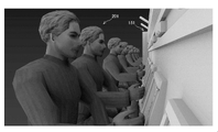
図1に示す管理システム2は、パチンコ店等の遊技店10を経営する団体(例えば企業)が遊技店10を管理するための管理システムである。図1に示すように、管理システム2は、遊技店10内に設けられる4個のカメラ50~53と、管理装置70と、端末装置100と、を備える。本実施例では、4個のカメラ50~53と管理装置70とは、有線ケーブル4を介して通信可能に有線接続されている。管理装置70と端末装置100とは、有線ケーブル6を介して通信可能に有線接続されている。なお、各装置50~53,70は、有線接続ではなく、無線接続されていてもよい。遊技店10内には、さらに、複数個の遊技台150と、1個のカウンタ160と、が設けられており、カウンタ160の背後の棚には、遊技媒体と交換可能な複数個の景品165が載置されている。また、遊技店10内には、複数名の遊技台150の利用者200が存在している。なお、図面では、遊技台、利用者、及び、景品の一部のみに参照番号が付されている。各遊技台150は、パチンコ玉を遊技媒体とするパチンコ機と、その周辺機器(例えば、呼出ランプ、アウトメータ、サンド等)を含む装置である。カウンタ160は、遊技媒体を景品165に交換する等の事務処理を行うための設備である。遊技台150とカウンタ160と景品165と利用者200とは、4個のカメラ50~53による撮影の対象である。以下では、遊技台150とカウンタ160と景品165と利用者200とのうち、経時的な動きが大きい景品165と利用者200とを「対象物」と呼び、経時的な動きが小さい遊技台150とカウンタ160とを「背景」と呼ぶ。
(First Example)
(Configuration of management system 2; FIG. 1)
The management system 2 shown in FIG. 1 is a management system for an organization (for example, a company) that manages a
(カメラ50~53の構成;図1)
4個のカメラ50~53は、遊技店10内を異なる角度から撮影するための撮影装置である。各カメラ50~53は、遊技店10内の対象物及び背景をリアルタイムで(即ち連続的に)撮影することができる。各カメラ50~53は、撮影された対象物及び背景の撮影画像を表わす撮影画像データを有線ケーブル4を介して管理装置70に供給する。
(Structure of
The four
(管理装置70の構成;図2)
続いて、管理装置70について説明する。管理装置70は、例えば、遊技店10を経営する団体によって設置されている装置であって、遊技店10内の状況を管理するための装置である。管理装置70は、例えばホールコンピュータである。他の例では、管理装置70は、ホールコンピュータを介して4個のカメラ50~53及び端末装置100と通信可能に有線接続されているサーバであってもよい。図3に示すように、管理装置70は、表示部72と、操作部74と、通信インターフェース76と、制御部78と、メモリ80と、を備える。表示部72は、様々な情報を表示するためのディスプレイである。操作部74は、キーボードとマウスを含み、管理装置70の管理者の操作を受け付ける。また、操作部74は、表示部72と一体として構成されるタッチパネルを含んでもよい。通信インターフェース76は、有線ケーブル4,6に接続されている。通信インターフェース76は、有線ケーブル4,6を介して、カメラ50~53及び端末装置100との通信を実行可能である。以下では、インターフェースのことを「I/F」と記載する。
(Configuration of
Subsequently, the
制御部78は、メモリ80に記憶されている各種プログラムに従って、後述の表示処理(図4参照)及び切替処理(図6参照)を含む様々な処理を実行する。メモリ80は、背景画像データ81と3D背景画像データ82とグラフィック生成プログラム84とグラフィック表示プログラム86とを含む各種プログラムを記憶している。
The
背景画像データ81は、各カメラ50~53によって予め撮影された背景(即ち、遊技台150及びカウンタ160)の撮影画像を表わす画像データである。背景画像データ81は、カメラ50~53のそれぞれから予め取得され、メモリ80に格納される。即ち、背景画像データ81には、カメラ50~53のそれぞれに対応する合計4個の背景画像データが含まれている。
The
3D背景画像データ82は、遊技店10内の背景(即ち、遊技台150及びカウンタ160)の3D画像を表わす画像データである。3D背景画像データ82は、以下のようにして生成される。即ち、メモリ80は、遊技店10内の背景を構成する構造物(即ち遊技台150及びカウンタ160)のそれぞれの大きさ、配置されている位置等を特定するための数値データ(即ち、モデルデータ)を予め記憶している(図示省略)。3D背景画像データ82は、当該モデルデータに基づいて、グラフィック設計プログラム(例えば、CAD(Computer-Aided Designの略)システム)を利用して予め生成されている。即ち、本実施例では、3D背景画像データ82は、モデルデータに基づいて予め生成された仮想的な3D背景画像を表わすデータを含んでいる。
The 3D
グラフィック生成プログラム84は、4個のカメラ50~53のそれぞれによって撮影された撮影画像を表わす合計4個の撮影画像データに基づいて、1個の3D画像を表わす3D画像データを生成するための生成プログラム(例えばreprojectImageTo3D等)である。グラフィック生成プログラム84は、任意の手段によって予めメモリ80内にインストールされている。
The
グラフィック表示プログラム86は、WebGL規格に従った表示プログラムであって、グラフィック生成プログラム84によって生成された3D画像データによって表わされる3D画像を表示させるための表示プログラム(例えば、「three.js」、「Away3D」、「Babylon.js」等)である。WebGL規格とは、ウェブブラウザ上で3D画像を表示させるための標準的な規格である。WebGL規格では、HTMLのcanvas要素が用いられる。グラフィック表示プログラム86は、3D画像を用いて情報を視覚的に容易に把握できるように可視化するためのプログラムと言い換えてもよい。グラフィック表示プログラム86は、任意の手段によって予めメモリ80内にインストールされている。
The graphic display program 86 is a display program according to the WebGL standard, and is a display program for displaying a 3D image represented by 3D image data generated by the graphic generation program 84 (for example, "three.js", "three.js", " "Away3D", "Babylon.js", etc.). The WebGL standard is a standard for displaying 3D images on a web browser. In the WebGL standard, the HTML canvas element is used. The graphic display program 86 may be paraphrased as a program for visualizing information so that it can be easily visually grasped by using a 3D image. The graphic display program 86 is pre-installed in the
(端末装置100の構成;図3)
端末装置100は、管理装置70によって生成された出力画面データ(詳しくは後述する)を取得して、出力画面データによって表わされる出力画面を表示するための装置である。本実施例では、端末装置100は、デジタルサイネージ端末(即ちデジタルディスプレイ端末)である。端末装置100は、例えば、遊技店10の入口近傍に配置されている。他の例では、端末装置100は、遊技店10内、遊技店10の駐車場等、遊技店10内外の任意の場所等に配置されていてもよい。変形例では、端末装置100は、据置型PC、携帯型PC、携帯電話等であってもよい。なお、端末装置100が携帯型の装置である場合には、持ち運びの観点から端末装置100は管理装置70と無線接続されているのが好ましい。図3に示すように、端末装置100は、表示部102と、操作部104と、通信I/F106と、制御部108と、メモリ110と、を備える。表示部102は、様々な情報を表示するためのディスプレイである。操作部104は、複数個のキーを有し、端末装置100の利用者の操作を受け付ける。なお、変形例において、端末装置100がPC等である場合には、操作部104は、キーボードとマウスを含んでいてもよい。また、操作部104は、表示部72と一体として構成されるタッチパネルを含んでもよい。通信I/F106は、有線ケーブル6を介して、管理装置70と通信を行うためのI/Fである。
(Configuration of
The
制御部108は、メモリ110に記憶されている各種プログラムに従って、後述の表示処理(図5参照)及び切替処理(図6参照)を含む様々な処理を実行する。メモリ110は、ブラウザプログラムを含む各種プログラムを記憶しているが、グラフィック表示プログラム(図2の符号86参照)を記憶していない。
The
(管理装置70の表示処理;図4)
続いて、図4を参照して、管理装置70の制御部78が実行する表示処理を説明する。管理装置70の電源がオンされると、制御部78は、図4の処理を開始する。S10では、制御部78は、4個のカメラ50~53のそれぞれから、有線ケーブル4を介して、当該カメラが現在撮影している遊技店10内の撮影画像を表わす撮影画像データを取得することを監視する。撮影画像データは、対象物の画像を表わす対象物撮影画像データと、背景の画像を表わす背景撮影画像データと、を含む。制御部78は、4個のカメラ50~53のそれぞれから撮影画像データを取得する場合(S10でYES)に、S15に進む。この場合、制御部78は、カメラ50~53から合計4個の撮影画像データを取得する。
(Display processing of
Subsequently, with reference to FIG. 4, the display process executed by the
S15では、制御部78は、S10で取得された各撮影画像データから対象物撮影画像データを抽出する。具体的には、まず、制御部78は、カメラ50による撮影画像データ(即ち対象物撮影画像データ及び背景撮影画像データ)から、カメラ50によるメモリ80内の背景画像データ81を差し引く。これにより、対象物画像(即ち利用者200及び景品165の画像)を表わす対象物撮影画像データが抽出される。同様に、制御部78は、カメラ51~53による撮影画像データについても同様の処理を実行する。これにより、カメラ50~53に由来する4個の対象物撮影画像データが抽出される。
In S15, the
S20では、制御部78は、グラフィック生成プログラム84を利用して、S15で抽出済みの4個の対象物撮影画像データに基づいて、対象物の3D画像を表わす1個の3D対象物画像データを生成する。
In S20, the
S25では、制御部78は、S20で生成済みの3D対象物画像データと、メモリ80内の3D背景画像データ82と、グラフィック表示プログラム86とを利用して、対象物3D画像と背景の3D画像とを含む出力画面を表わす出力画面データを生成する。
In S25, the
S30では、制御部78は、出力画面データに従って、表示部72に出力画面(後述の図7~図12参照)を表示させる。
In S30, the
S35では、制御部78は、有線ケーブル6を介して、出力画面データを端末装置100に供給する。制御部78は、S35を終えると、S10に戻る。
In S35, the
(端末装置100の表示処理;図5)
続いて、図5を参照して、端末装置100の制御部108が実行する表示処理の内容を説明する。端末装置100の電源がオンされると、制御部108は、図5の処理を開始する。S110では、制御部108は、有線ケーブル6を介して、管理装置70から出力画面データを取得することを監視する。制御部108は、管理装置70から出力画面データを取得する場合(S110でYES)に、S112に進む。
(Display processing of
Subsequently, with reference to FIG. 5, the contents of the display process executed by the
S112では、制御部108は、S110で取得済みの出力画面データに従って出力画面を表示部102に表示する。出力画面は、図4のS30の出力画面と同様である。制御部108は、S112を終えると、S110に戻る。
In S112, the
(管理装置70及び端末装置100の切替処理;図6)
続いて、図6を参照して、管理装置70の制御部78と、端末装置100の制御部108と、が実行する切替処理の内容を説明する。以下では、制御部78が切替処理の実行主体である場合について説明し、制御部108が実行主体である場合については、制御部78が実行主体である場合と同様であるため、説明を省略する。図4のS30において出力画面が表示されると、制御部78は、図6の処理を開始する。この場合に、表示されている出力画面は、対象物の3D画像と背景の3D画像とを所定の視点(以下では「初期の視点」と呼ぶ)から見た初期画像を含む初期出力画面である。
(Switching process of
Subsequently, with reference to FIG. 6, the contents of the switching process executed by the
S210では、制御部78は、初期画像の視点を切り換えるための切替指示がユーザによって操作部74に与えられることを監視する。切替指示は、例えば、カーソルキーを押下する操作、初期出力画面内の拡大表示したいオブジェクトを指定する操作等である。制御部78は、切替指示が与えられる場合(S210でYES)に、S215に進む。
In S210, the
S215では、制御部78は、出力画面データに従って、表示部72に、対象物の3D画像と背景の3D画像とを初期の視点とは異なる切替後の視点から見た切替後画像を含む切替後出力画面を表示させる。制御部78は、S215を終えると、S210に戻る。
In S215, the
(出力画面例;図7~図12)
続いて、図7~図12を参照して、出力画面の例について説明する。図7は、初期出力画面を示す。図7の初期出力画面は、斜め上の視点から見たビューであり、遊技台150を表わす3D画像151と、カウンタ160を表わす3D画像161と、景品165を表わす3D画像166と、利用者200を表わす3D画像201と、を含む。初期出力画面を見た者は、利用者200が遊技台150で遊技している様子、景品165の増減等を大まかに把握することができる。また、図4~図6の処理が繰り返し実行されることによって、初期出力画面が更新されるので、利用者200の動き、景品165の増減等も随時更新される。これにより、初期出力画面を見た者は、遊技店内の状況を経時的に把握することができる。図7の初期出力画面は、視点切替指示が与えられることによって、図8~図12の切替後出力画面に切り替わる。
(Example of output screen; FIGS. 7 to 12)
Subsequently, an example of the output screen will be described with reference to FIGS. 7 to 12. FIG. 7 shows an initial output screen. The initial output screen of FIG. 7 is a view viewed from an obliquely upper viewpoint, and is a
図8は、カウンタ160の背後の景品棚(即ち景品165)を正面から見る視点に切り替えた場合の出力画面を示す。図8の出力画面を見た者は、景品165の増減の様子をより容易に把握することができ、引き渡される景品165の傾向も把握し易くなる。
FIG. 8 shows an output screen when the prize shelf (that is, the prize 165) behind the
図9は、図7の初期出力画面における遊技店10内の奥側周辺を中心的に見る視点に切り替えた場合の出力画面を示す。図9の出力画面では、図7の初期出力画面において奥の方に示されている遊技台150とカウンタ160と利用者200とが手前に示されている。これにより、図9の出力画面を見た者は、図7の初期出力画面では把握しにくい店内の奥側の遊技台150とカウンタ160と利用者200との様子も容易に把握することができる。
FIG. 9 shows an output screen in the initial output screen of FIG. 7 when the viewpoint is switched to a viewpoint in which the periphery of the back side in the
図10は、遊技店10内全体を俯瞰するビューに切り替えた場合の出力画面を示す。図10の出力画面を見た者は、例えば、利用者200が、遊技店10内のどのエリアに集中しているのか等、遊技店10内全体の利用者200の動きを把握することができる。
FIG. 10 shows an output screen when the view is switched to a bird's-eye view of the entire inside of the
図11は、複数の利用者200の手元と表情を確認可能なビューに切り替えた場合の出力画面である。図11の出力画面を見た者は、例えば、遊技中の利用者200の手の動き、表情等を観察することによって、不審な動きをしている利用者200を特定することができる。
FIG. 11 is an output screen when the hands and facial expressions of the plurality of
図12は、不審な動きをしている人物として特定された利用者200の手元をさらに詳細に確認可能なビューに切り替えた場合の出力画面である。図11の出力画面は、特に、不審な動きをしている人物として特定された利用者200の手元の俯瞰図である。図12の出力画面を見た者は、当該人物が実際に不正行為をしていないかを確認することができ、不正行為を発見及び防止することができる。
FIG. 12 is an output screen when the hand of the
(作用効果)
本実施例の管理装置70は、4個のカメラ50~53のそれぞれから取得される対象物撮影画像データに基づいて、3D対象物画像データを生成する(図4のS10~S20)。そして、管理装置70は、3D対象物画像データとグラフィック表示プログラム86とを利用して、対象物(即ち利用者200及び景品165)の3D画像を含む出力画面を表わす出力画面データを生成し(S25)、出力画面データに従って、表示装置に出力画面を表示させる(S30)。出力画面は、3D画像を含むため、遊技店10内の状況を立体的に表示することができる。従って、出力画面が平面的な画像等のみを含み、3D画像を含まない従来の構成と比べて、出力画面を見た者が遊技店10内の状況を容易に直感的に把握することができる。
(Action effect)
The
また、本実施例では、管理装置70は、メモリ80に予め記憶済みの3D背景画像データ82を利用して、遊技台150の3D画像と、カウンタ160の画像と、を含む出力画面を表わす出力画面データを生成し(図4のS25)、出力画面を表示する(S30)。これにより、出力画面を見た者は遊技店10内の遊技台150及びカウンタ160の状況も容易に直感的に把握することができる。
Further, in the present embodiment, the
また、本実施例では、出力画面内の背景画像は、モデルデータに由来する3D背景画像データ82によって表わされているので、リアルには表現されていない(例えば、背景の細部が省略されて仮想的に表現されている)。一方、出力画面内の対象物画像は、カメラ50~53による撮影画像データに由来する3D対象物画像データによって表わされているので、比較的リアルに表現されている。そのため、出力画面では、リアルに表現されている対象物画像が目立つ。これにより、出力画面を見た者は、対象物画像に注目しやすくなる。
Further, in this embodiment, the background image in the output screen is represented by the 3D
また、本実施例では、初期出力画面が管理装置70に表示されている間に、切替指示が管理装置70に与えられる場合(図6のS210でYES)に、切替後出力画面を表示させる(S215)。これにより、管理装置70の利用者は、複数の視点から見た対象物の3D画像を見ることができる(図7~図12参照)。また、図7~図12の例に示されるように、管理装置70の利用者は、対象物の3D画像を見ながら、対象物の3D画像を見る視点を所望の視点に切り替えたり、対象物の3D画像の中の所望の部分をズームしたりすることができる。
Further, in this embodiment, when a switching instruction is given to the
また、本実施例では、端末装置100は、管理装置70から出力画面データを取得し(図5のS110でYES)、出力画面を表示する(S112)。これにより、端末装置100の利用者は、端末装置100において出力画面を見ることができる。
Further, in this embodiment, the
(対応関係)
本実施例と請求項の記載との対応関係を説明しておく。4個のカメラ50~53が、「複数個の画像撮影装置」の一例である。遊技店10が「所定の空間」の一例である。管理装置70の表示部72が、「表示装置」及び「管理表示部」の一例である。初期画像、初期出力画面が、それぞれ、「第1の画像」、「第1の出力画面」の一例である。切替後画像、切替後出力画面が、それぞれ、「第2の画像」、「第2の出力画面」の一例である。管理装置70、端末装置100によって実行される図6のS210の視点切替指示が、それぞれ、「第1種の切替指示」、「第2種の切替指示」の一例である。端末装置100の表示部102が、「端末表示部」の一例である。モデルデータに基づいて生成される3D背景画像データ82が、「第1種の3D背景データ」に基づいて生成されるデータの一例である。
(Correspondence)
The correspondence between this embodiment and the description of the claims will be described. The four
(第2実施例)
第1実施例と異なる点を中心に説明する。本実施例では、管理装置70の表示処理(図4)の内容、及び、端末装置100の表示処理(図5)が第1実施例とは異なる。
(Second Example)
The points different from the first embodiment will be mainly described. In this embodiment, the content of the display process of the management device 70 (FIG. 4) and the display process of the terminal device 100 (FIG. 5) are different from those of the first embodiment.
本実施例では、図4のS35において、管理装置70の制御部78は、有線ケーブル6を介して、S20で生成済みの3D対象物画像データと、メモリ80内の3D背景画像データ82と、グラフィック表示プログラム86と、を端末装置100に送信する。
In this embodiment, in S35 of FIG. 4, the
本実施例では、図5のS110において、端末装置100の制御部108は、有線ケーブル6を介して、3D対象物画像データと3D背景画像データ82とグラフィック表示プログラム86とを管理装置70から取得することを監視する。制御部108は、3D対象物画像データと3D背景画像データ82とグラフィック表示プログラム86とを管理装置70から取得する場合(S110でYES)に、S111に進む。S111では、制御部108は、管理装置70から取得された3D対象物画像データと3D背景画像データとグラフィック表示プログラムとを用いて、図4のS25と同様の手法で出力画面データを生成する。続くS112では、制御部108は、S111で生成された図出力画面データに従って、表示部102に出力画面を表示させる。
In this embodiment, in S110 of FIG. 5, the
(作用効果)
本実施例の管理システム2では、管理装置70だけではなく、端末装置100も出力画面データを生成している。本実施例でも、第1実施例と同様の効果を発揮することができる。さらに、本実施例では、端末装置100は、管理装置70からグラフィック表示プログラム86を取得するので(図5のS110でYES)、グラフィック表示プログラム86を予め記憶していなくても、出力画面を表示することができる(S112)。
(Action effect)
In the management system 2 of this embodiment, not only the
(第3実施例)
第1実施例と異なる点を中心に説明する。本実施例では、管理装置70の表示処理(図4)の内容が第1実施例とは異なる。
(Third Example)
The points different from the first embodiment will be mainly described. In this embodiment, the content of the display process (FIG. 4) of the
本実施例では、図4のS25において、管理装置70の制御部78は、S20で生成済みの3D対象物画像データと、グラフィック表示プログラム86とを利用して、出力画面を表わす出力画面データを生成する。出力画面は、対象物3D画像を含むが、背景3D画像を含まない。本実施例でも、出力画面は、遊技店10内の状況(特に対象物である利用者及び景品)を立体的に表示しているので、出力画面を見た者が遊技店10内の状況を容易に直感的に把握することができる。
In this embodiment, in S25 of FIG. 4, the
また、本実施例の出力画面が背景3D画像を含まないため、出力画面を見た者は、遊技店10内の人物の特徴と、当該人物が存在する位置と、を容易に把握することができる。これにより、例えば、出力画面を見た者は、不審な動きをしている利用者200を特定したり、遊技店10に頻繁に来店する利用者200を見つけて声掛けしたり、遊技店10内の通路を走り回る子どもに注目したりすることができる。
Further, since the output screen of this embodiment does not include the background 3D image, the person who sees the output screen can easily grasp the characteristics of the person in the
図16は、対象物3D画像である利用者200a~200eの画像を含む出力画面の一例を示す。図16の出力画面では、利用者200a~200eの画像が並べて表示されている。さらに、各利用者200a~200eの性別、年齢、及び遊技している遊技台150の識別番号が各利用者200a~200eの画像に対応付けて表示されている。例えば、制御部78は、公知の顔認識技術によって対象物撮影画像データから利用者の顔を表す顔画像を抽出し、顔画像から特定される特徴点に基づいて、利用者の性別、年齢を取得し、利用者の近傍の遊技台150から有線ケーブル(図示省略)を介して遊技台150の識別番号を取得する。そして、制御部78は、これらの取得された情報を利用者200a~200eに対応付けて表示する。
FIG. 16 shows an example of an output screen including images of
以上、本明細書で開示する技術の実施例を詳細に説明したが、上記の実施例は例示に過ぎず、特許請求の範囲を限定するものではない。特許請求の範囲に記載の技術には、以上に例示した具体例を様々に変形、変更したものが含まれる。例えば、以下の変形例を採用してもよい。 Although examples of the techniques disclosed in the present specification have been described in detail above, the above examples are merely examples and do not limit the scope of claims. The techniques described in the claims include various modifications and modifications of the specific examples exemplified above. For example, the following modification may be adopted.
(変形例1)図4のS25の出力画面データは、利用者を表わす画像に対応付けて表示される情報を含んでいてもよい。上述したように、例えば、制御部78は、利用者の顔を表す顔画像から特定される特徴点に基づいて、利用者の性別、年齢等の属性情報を取得する。また、制御部78は、利用者の近傍の遊技台150から有線ケーブルを介して遊技情報(遊技台150の識別番号、遊技の開始時間、成績等)を取得する。そして、制御部78は、属性情報及び遊技情報を含む出力画面データを生成する。この場合、S30の出力画面では、利用者を表わす画像に対応付けて、属性情報及び遊技情報が表示される。図13には、遊技情報として、利用者200を表わす3D画像201に王冠の3D画像300が重ねて表示される例が示されている。利用者200の遊技成績が優れている程、表示される王冠の数が多くなる。また、図14には、遊技情報として、3D画像201の近傍に遊技成績を表わす棒グラフの3D画像400が表示される例が示されている。その他の遊技情報の例として、利用者の表情を遊技成績に応じた表情に加工するための情報、利用者の周りに集まるキャラクターの画像を表わす情報、遊技媒体が入った箱の画像を表わす情報等が挙げられる。なお、属性情報について、属性情報が示す年齢が所定の年齢以下である場合に、注意を喚起するためのマークが表示されてもよい。
(Modification 1) The output screen data of S25 in FIG. 4 may include information displayed in association with an image representing a user. As described above, for example, the
さらに、制御部78は、属性情報と遊技情報とを対応付けることによって、利用者ごとに遊技情報の履歴をメモリ80に記憶させることもできる。この場合、S30の出力画面では、利用者を表わす3D画像に対応付けて、履歴が表示されてもよい。
Further, the
(変形例2)図4のS25の出力画面データは、3D対象物画像データを含まず、上記の遊技情報を含んでいてもよい。そして、S30の出力画面では、3D対象物画像が表示されず、遊技情報が表示されてもよい。この場合、遊技情報は、例えば、成績に応じたキャラクタの画像、成績を表わすグラフ等の態様で表示される。 (Modification 2) The output screen data of S25 in FIG. 4 does not include 3D object image data, but may include the above-mentioned game information. Then, the 3D object image may not be displayed on the output screen of S30, and the game information may be displayed. In this case, the game information is displayed in the form of, for example, an image of a character corresponding to the result, a graph showing the result, or the like.
(変形例3)各実施例の管理システム2は、4個のカメラ50~53を備える。変形例では、カメラの個数は4個に限られず、2個であってもよいし、3個以上であってもよい。カメラの個数が2個以上であれば、管理装置70は、2個以上のカメラのそれぞれに由来する2個以上の対象物撮影画像データに基づいて、3D対象物画像データを生成可能である。従って、変形例でも各実施例と同様の効果を発揮することができる。即ち、「画像撮影装置」の個数は、2個以上であればよい。
(Modification 3) The management system 2 of each embodiment includes four
(変形例4)「所定の空間」は、遊技店10に限られず、例えば、商店、映画館、公園等、撮影の対象が存在する空間であればどのような空間であってもよい。
(Modification 4) The “predetermined space” is not limited to the
(変形例5)各実施例では、背景画像データ81及び3D背景画像データ82が管理装置70のメモリ80に予め記憶されているが、変形例では、これらのデータが記憶されていなくてもよい。本変形例では、管理装置70の制御部78は、図4のS15を省略し、S20において、グラフィック生成プログラム84を利用して、カメラ50~53に由来する4個の撮影画像データに基づいて、対象物の3D画像と背景の3D画像とを表わす3D画像データを生成する。即ち、本変形例では、3D背景画像データと3D画像データとが同時に生成されているといえる。即ち、「記憶装置」は省略可能である。また、本変形例では、遊技台150、カウンタ160、景品165、及び利用者200の全てが、「対象物」の一例であると考えることもできる。
(Modification 5) In each embodiment, the
(変形例6)各実施例では、出力画面において、対象物と背景の双方が3D画像として表されている。これに限られず、出力画面では、対象物の3D画像と、背景の2D画像を含んでいてもよい。一般的に言うと、出力画面データは、対象物の3D画像を含む出力画面を表わしていればよい。 (Modification 6) In each embodiment, both the object and the background are represented as 3D images on the output screen. Not limited to this, the output screen may include a 3D image of the object and a 2D image of the background. Generally speaking, the output screen data may represent an output screen including a 3D image of the object.
(変形例7)3D背景画像データ82は、モデルデータに基づいて予め生成されるデータでなくてもよく、各カメラ50~53によって撮影された背景画像を表わす背景画像データ81と、グラフィック生成プログラム84と、を利用して生成されたデータであってもよい。この場合の3D背景画像データ82が、「第2種の3D背景データ」に基づいて生成されるデータの一例である。また、別の変形例では、3D背景画像データ82のうちの一部が、上記のように背景画像データ81を利用して生成され、他の一部が、各実施例のようにモデルデータを利用して生成されてもよい。
(Modification 7) The 3D
(変形例8)第1実施例では、S35において、管理装置70の制御部78は、有線ケーブル6を介して、出力画面データを端末装置100に供給する。第2実施例では、S35において、制御部78は、有線ケーブル6を介して、S20で生成済みの3D対象物画像データと、メモリ80内の3D背景画像データ82と、グラフィック表示プログラム86と、を端末装置100に送信する。変形例では、管理装置70の制御部78は、出力画面を表示させる対象の端末装置の能力に応じて、出力画面データを送信すること(即ち第1実施例のS35の処理)と、S20で生成済みの3D対象物画像データと、メモリ80内の3D背景画像データ82と、グラフィック表示プログラム86と、を端末装置に送信すること(即ち第2実施例のS35の処理)と、を切り替えて実行してもよい。
(Modification 8) In the first embodiment, in S35, the
(変形例9)各実施例では、視点切替指示が与えられる場合(図6のS210でYES)に、出力画面の視点が切り替わる(S215)。変形例では、例えば、定期的に出力画面の視点が切り替わってもよいし、出力画面の視点が固定されていてもよい。即ち、「第1種の切替指示」が管理装置に与えられなくてもよいし、「第2種の切替指示」が端末装置に与えられなくてもよい。 (Modification 9) In each embodiment, when the viewpoint switching instruction is given (YES in S210 in FIG. 6), the viewpoint of the output screen is switched (S215). In the modified example, for example, the viewpoint of the output screen may be switched periodically, or the viewpoint of the output screen may be fixed. That is, the "first-class switching instruction" may not be given to the management device, and the "second-class switching instruction" may not be given to the terminal device.
(変形例10)出力画面は、管理装置70の表示部72のみで表示され、端末装置100の表示部102では表示されなくてもよい。即ち、「端末装置」及び「供給部」は省略可能である。
(Modification 10) The output screen may be displayed only on the
(変形例11)出力画面は、端末装置100の表示部102のみで表示され、管理装置70の表示部72では表示されなくてもよい。この場合、端末装置100が「表示装置」の一例である。
(Modification 11) The output screen may be displayed only on the
(変形例12)上記の各実施例では、管理装置70は、表示部72、操作部74、通信I/F76、制御部78、及び、メモリ80をすべて含む1個の装置として構成されている。これに限られず、管理装置70は、上記の各構成要素72~80が、2個以上の装置に分かれて存在するように構成されていてもよい。例えば、管理装置70は、表示部72、操作部74、通信I/F76、及び、制御部78を含む第1の装置と、メモリ80(例えば外部メモリ)を含む第2の装置と、の組合せによって構成されていてもよい。端末装置100についても同様である。
(Modification 12) In each of the above embodiments, the
(変形例13)図15に示されるように、管理装置70は、物理的に分離した2個の装置70a,70bで構成されていてもよい。装置70aは、操作部74aと通信I/F76aと制御部78aとメモリ80aとを備える。装置70bは、表示部72と操作部74bと通信I/F76bと制御部78bとメモリ80bとを備える。操作部74a,74bは、操作部74と同様の構成を備える。通信I/F76aは、有線ケーブル4,8に接続されている。通信I/F76aは、有線ケーブル4,8を介して、カメラ50~53及び装置70bとの通信を実行可能である。通信I/F76bは、有線ケーブル6,8に接続されている。通信I/F76bは、有線ケーブル6,8を介して、装置70a及び端末装置100との通信を実行可能である。メモリ80aは、S15,S20で利用される背景画像データ81及びグラフィック生成プログラム84を記憶している。メモリ80bは、S25,S35で利用される3D背景画像データ82及びグラフィック表示プログラム86を記憶している。
(Modification 13) As shown in FIG. 15, the
制御部78aは、図4の表示処理のうちのS10~S20を実行し、通信I/F76aを介して、3D対象物画像データを装置70bに供給する。制御部78bは、通信I/F76bを介して、装置70aから3D対象物画像データを取得し、S25~S35を実行する。
The
また、本明細書又は図面に説明した技術要素は、単独であるいは各種の組合せによって技術的有用性を発揮するものであり、出願時請求項記載の組合せに限定されるものではない。また、本明細書又は図面に例示した技術は複数目的を同時に達成するものであり、そのうちの一つの目的を達成すること自体で技術的有用性を持つものである。 Further, the technical elements described in the present specification or the drawings exhibit technical usefulness alone or in various combinations, and are not limited to the combinations described in the claims at the time of filing. In addition, the techniques exemplified in this specification or drawings achieve a plurality of purposes at the same time, and achieving one of the purposes itself has technical usefulness.
2:管理システム
4,6:有線ケーブル
10:遊技店
50~53:カメラ
70:管理装置
72:表示部
74:操作部
76:通信インターフェース
78:制御部
80:メモリ
81:背景画像データ
82:3D背景画像データ
84:グラフィック生成プログラム
86:グラフィック表示プログラム
100:端末装置
102:表示部
104:操作部
106:通信インターフェース
108:制御部
110:メモリ
150:遊技台
151,161,201,300,400:3D画像
160:カウンタ
165:景品
200,200a~200e:利用者
2:
Claims (4)
前記管理装置は、
所定の空間内に設けられる画像撮影装置から、前記画像撮影装置が現在撮影している前記所定の空間内の対象物の撮影画像を表わす対象物撮影画像データを取得する管理取得部と、
前記画像撮影装置から取得される前記対象物撮影画像データに基づいて、前記対象物の3D画像を表わす3D対象物データを生成する第1データ生成部と、
前記3D対象物データと、WebGL規格に従った表示プログラムとを利用して、前記対象物の3D画像を含む出力画面を表わす出力画面データを生成する第2データ生成部と、
前記出力画面データに従って、表示装置に前記出力画面を表示させるための出力処理を実行する出力部と、
前記所定の空間内の前記対象物の背景の3D画像を表わす3D背景データを予め記憶する記憶装置と、を備え、
前記第2データ生成部は、前記3D対象物データと、前記記憶装置内の前記3D背景データと、前記表示プログラムと、を利用して、前記所定の空間における前記対象物と前記対象物の前記背景との位置関係に対応する位置関係で配置される前記対象物の3D画像と前記背景の3D画像とを含む前記出力画面を表わす前記出力画面データを生成し、
前記3D背景データは、
(a)前記背景に含まれる要素を特定するために予め定められたモデルデータに基づいて生成された第1種の3D画像を表わす第1種の3D背景データと、
(b)前記画像撮影装置が予め撮影した前記背景の撮影画像を表わす背景撮影画像データに基づいて生成された第2種の3D画像を表わす第2種の3D背景データと、
のうちの少なくとも一方に基づいて生成されたデータであり、
前記出力処理は、前記出力画面データを前記端末装置に供給することを含み、
前記端末装置は、
端末表示部と、
前記管理装置から前記出力画面データを取得する端末取得部と、
前記出力画面データに従って、前記端末表示部に前記出力画面を表示させる、表示制御部と、を備え、
前記表示制御部は、
前記出力画面データに従って、前記端末表示部に、前記対象物の3D画像を第1の視点から見た第1の画像を含む第1の出力画面を表示させ、
前記第1の出力画面が前記端末表示部に表示されている間に、視点を切り換えるための第2種の切替指示が前記端末装置に与えられると、前記出力画面データに従って、前記端末表示部に、前記対象物の3D画像を前記第1の視点とは異なる第2の視点から見た第2の画像を含む第2の出力画面を表示させ る、管理システム。 tube A management system including a physical device and a terminal device configured separately from the management device.
The management device is
A management acquisition unit that acquires object-photographed image data representing an image of an object in the predetermined space currently being imaged by the image-taking device from an image-taking device provided in the predetermined space.
A first data generation unit that generates 3D object data representing a 3D image of the object based on the object photographed image data acquired from the image photographing apparatus.
A second data generation unit that generates output screen data representing an output screen including a 3D image of the object by using the 3D object data and a display program according to the WebGL standard.
An output unit that executes output processing for displaying the output screen on the display device according to the output screen data.
A storage device for preliminarily storing 3D background data representing a 3D image of the background of the object in the predetermined space is provided.
The second data generation unit uses the 3D object data, the 3D background data in the storage device, and the display program to describe the object and the object in the predetermined space. The output screen data representing the output screen including the 3D image of the object and the 3D image of the background arranged in the positional relationship corresponding to the positional relationship with the background is generated.
The 3D background data is
(A) A type 1 3D background data representing a type 1 3D image generated based on a predetermined model data for specifying an element included in the background.,
((b) Type 2 3D background data representing a type 2 3D image generated based on background captured image data representing the background captured image captured in advance by the image capturing device, and
Data generated based on at least one of
The output process includes supplying the output screen data to the terminal device.
The terminal device is
Terminal display and
A terminal acquisition unit that acquires the output screen data from the management device, and
A display control unit for displaying the output screen on the terminal display unit according to the output screen data is provided.
The display control unit
According to the output screen data, the terminal display unit is made to display a first output screen including a first image of the 3D image of the object viewed from the first viewpoint.
When a second type of switching instruction for switching the viewpoint is given to the terminal device while the first output screen is displayed on the terminal display unit, the terminal display unit is in accordance with the output screen data. , Display a second output screen including a second image of the 3D image of the object viewed from a second viewpoint different from the first viewpoint. Management system.
前記出力処理は、
前記出力画面データに従って、前記管理表示部に、前記対象物の3D画像を第1の視点から見た第1の画像を含む第1の出力画面を表示させることと、
前記第1の出力画面が前記管理表示部に表示されている間に、視点を切り換えるための第1種の切替指示が前記管理装置に与えられる場合に、前記出力画面データに従って、前記管理表示部に、前記対象物の3D画像を前記第1の視点とは異なる第2の視点から見た第2の画像を含む第2の出力画面を表示させることと、を含む、
請求項1に記載の管理システム。 The management device further includes a management display unit which is the display device.
The output processing is
According to the output screen data, the management display unit is displayed with a first output screen including a first image of the 3D image of the object viewed from the first viewpoint.
When the management device is given a first-class switching instruction for switching the viewpoint while the first output screen is displayed on the management display unit, the management display unit according to the output screen data. Including displaying a second output screen including a second image of the object as viewed from a second viewpoint different from the first viewpoint.
The management system according to claim 1.
前記第2データ生成部は、前記属性情報をさらに含む前記出力画面データを生成する、請求項1又は2に記載の管理システム。 The management device further includes an attribute acquisition unit that acquires attribute information representing the attributes of the object.
The management system according to claim 1 or 2, wherein the second data generation unit generates the output screen data including the attribute information.
前記管理装置は、
所定の空間内に設けられる画像撮影装置から、前記画像撮影装置が現在撮影している前記所定の空間内の対象物の撮影画像を表わす対象物撮影画像データを取得する管理取得部と、
前記画像撮影装置から取得される前記対象物撮影画像データに基づいて、前記対象物の3D画像を表わす3D対象物データを生成するデータ生成部と、
前記3D対象物データと、WebGL規格に従った表示プログラムと、を前記端末装置に供給する供給部と、備え、
前記端末装置は、
端末表示部と、
前記管理装置から取得された前記3D対象物データと、前記表示プログラムとを利用して、前記対象物の3D画像を含む出力画像を表す出力画面データを生成する端末側生成部と、
前記出力画面データに従って、前記端末表示部に前記出力画面を表示させる、表示制御部と、を備え、
前記表示制御部は、
前記出力画面データに従って、前記端末表示部に、前記対象物の3D画像を第1の視点から見た第1の画像を含む第1の出力画面を表示させ、
前記第1の出力画面が前記端末表示部に表示されている間に、視点を切り換えるための切替指示が前記端末装置に与えられると、前記出力画面データに従って、前記端末表示部に、前記対象物の3D画像を前記第1の視点とは異なる第2の視点から見た第2の画像を含む第2の出力画面を表示させ る、管理システム。 tube A management system including a physical device and a terminal device configured separately from the management device.
The management device is
A management acquisition unit that acquires object-photographed image data representing an image of an object in the predetermined space currently being imaged by the image-taking device from an image-taking device provided in the predetermined space.
A data generation unit that generates 3D object data representing a 3D image of the object based on the object photographed image data acquired from the image photographing apparatus.
A supply unit that supplies the 3D object data and a display program according to the WebGL standard to the terminal device is provided.
The terminal device is
Terminal display and
Using the 3D object data acquired from the management device and the display program,Represents an output image that includes a 3D image of the objectThe terminal side generator that generates the output screen data, and
A display control unit for displaying the output screen on the terminal display unit according to the output screen data is provided.,
The display control unit
According to the output screen data, the terminal display unit is made to display a first output screen including a first image of the 3D image of the object viewed from the first viewpoint.
When a switching instruction for switching the viewpoint is given to the terminal device while the first output screen is displayed on the terminal display unit, the object is displayed on the terminal display unit according to the output screen data. A second output screen including a second image viewed from a second viewpoint different from the first viewpoint is displayed. Management system.
Priority Applications (1)
| Application Number | Priority Date | Filing Date | Title |
|---|---|---|---|
| JP2016227147A JP7101331B2 (en) | 2016-11-22 | 2016-11-22 | Management device and management system |
Applications Claiming Priority (1)
| Application Number | Priority Date | Filing Date | Title |
|---|---|---|---|
| JP2016227147A JP7101331B2 (en) | 2016-11-22 | 2016-11-22 | Management device and management system |
Publications (2)
| Publication Number | Publication Date |
|---|---|
| JP2018084924A JP2018084924A (en) | 2018-05-31 |
| JP7101331B2 true JP7101331B2 (en) | 2022-07-15 |
Family
ID=62238292
Family Applications (1)
| Application Number | Title | Priority Date | Filing Date |
|---|---|---|---|
| JP2016227147A Active JP7101331B2 (en) | 2016-11-22 | 2016-11-22 | Management device and management system |
Country Status (1)
| Country | Link |
|---|---|
| JP (1) | JP7101331B2 (en) |
Families Citing this family (1)
| Publication number | Priority date | Publication date | Assignee | Title |
|---|---|---|---|---|
| JP6525229B1 (en) * | 2019-01-25 | 2019-06-05 | 株式会社 テクノミライ | Digital search security system, method and program |
Citations (10)
| Publication number | Priority date | Publication date | Assignee | Title |
|---|---|---|---|---|
| JP2000209569A (en) | 1999-01-19 | 2000-07-28 | Oki Electric Ind Co Ltd | Remote monitor, remote monitoring method and remote monitoring system |
| JP2002247585A (en) | 2001-02-15 | 2002-08-30 | Nippon Telegr & Teleph Corp <Ntt> | Method for transmitting moving image, method for receiving moving image, program for moving image transmitting processing, recording medium for the program, program for moving image receiving processing, recording medium for the program |
| WO2005076621A1 (en) | 2004-02-03 | 2005-08-18 | Matsushita Electric Industrial Co., Ltd. | Monitoring system and camera terminal |
| JP2008066864A (en) | 2006-09-05 | 2008-03-21 | Mitsubishi Electric Corp | Monitoring unit and monitoring program |
| JP2010504711A (en) | 2006-09-26 | 2010-02-12 | ハリス コーポレイション | Video surveillance system and method for tracking moving objects in a geospatial model |
| JP2011108086A (en) | 2009-11-19 | 2011-06-02 | Fuji Xerox Co Ltd | System for managing memorandum information, apparatus for processing memorandum information and program |
| JP2011151459A (en) | 2010-01-19 | 2011-08-04 | Mitsubishi Electric Corp | Composite display device |
| WO2012131816A1 (en) | 2011-03-28 | 2012-10-04 | 日本電気株式会社 | Person tracking device, person tracking method, and non-temporary computer-readable medium storing person tracking program |
| JP2015097060A (en) | 2013-11-15 | 2015-05-21 | 萬里科技股▲ふん▼有限公司 | Method for using 3d geometric data for representing and controlling virtual reality image in 3d space |
| WO2016038240A1 (en) | 2014-09-09 | 2016-03-17 | Nokia Technologies Oy | Stereo image recording and playback |
-
2016
- 2016-11-22 JP JP2016227147A patent/JP7101331B2/en active Active
Patent Citations (10)
| Publication number | Priority date | Publication date | Assignee | Title |
|---|---|---|---|---|
| JP2000209569A (en) | 1999-01-19 | 2000-07-28 | Oki Electric Ind Co Ltd | Remote monitor, remote monitoring method and remote monitoring system |
| JP2002247585A (en) | 2001-02-15 | 2002-08-30 | Nippon Telegr & Teleph Corp <Ntt> | Method for transmitting moving image, method for receiving moving image, program for moving image transmitting processing, recording medium for the program, program for moving image receiving processing, recording medium for the program |
| WO2005076621A1 (en) | 2004-02-03 | 2005-08-18 | Matsushita Electric Industrial Co., Ltd. | Monitoring system and camera terminal |
| JP2008066864A (en) | 2006-09-05 | 2008-03-21 | Mitsubishi Electric Corp | Monitoring unit and monitoring program |
| JP2010504711A (en) | 2006-09-26 | 2010-02-12 | ハリス コーポレイション | Video surveillance system and method for tracking moving objects in a geospatial model |
| JP2011108086A (en) | 2009-11-19 | 2011-06-02 | Fuji Xerox Co Ltd | System for managing memorandum information, apparatus for processing memorandum information and program |
| JP2011151459A (en) | 2010-01-19 | 2011-08-04 | Mitsubishi Electric Corp | Composite display device |
| WO2012131816A1 (en) | 2011-03-28 | 2012-10-04 | 日本電気株式会社 | Person tracking device, person tracking method, and non-temporary computer-readable medium storing person tracking program |
| JP2015097060A (en) | 2013-11-15 | 2015-05-21 | 萬里科技股▲ふん▼有限公司 | Method for using 3d geometric data for representing and controlling virtual reality image in 3d space |
| WO2016038240A1 (en) | 2014-09-09 | 2016-03-17 | Nokia Technologies Oy | Stereo image recording and playback |
Also Published As
| Publication number | Publication date |
|---|---|
| JP2018084924A (en) | 2018-05-31 |
Similar Documents
| Publication | Publication Date | Title |
|---|---|---|
| US9654734B1 (en) | Virtual conference room | |
| US8970623B2 (en) | Information processing system, information processing method, information processing device and tangible recoding medium recording information processing program | |
| JP4933164B2 (en) | Information processing apparatus, information processing method, program, and storage medium | |
| US9064335B2 (en) | System, method, device and computer-readable medium recording information processing program for superimposing information | |
| CN104936665B (en) | Cooperation augmented reality | |
| CN107771309A (en) | Three dimensional user inputs | |
| CN108273265A (en) | The display methods and device of virtual objects | |
| EP3383036A2 (en) | Information processing device, information processing method, and program | |
| US20160371888A1 (en) | Interactive information display | |
| US20190268587A1 (en) | Information processing device, information processing method, and program | |
| WO2012063560A1 (en) | Image processing system, image processing method, and storage medium storing image processing program | |
| CN112346572A (en) | Method, system and electronic device for realizing virtual-real fusion | |
| WO2020248711A1 (en) | Display device and content recommendation method | |
| JP2002247602A (en) | Image generator and control method therefor, and its computer program | |
| CN107079186A (en) | enhanced interactive television experience | |
| CN111862348A (en) | Video display method, video generation method, video display device, video generation device, video display equipment and storage medium | |
| CN107079139A (en) | There is no the augmented reality of physical trigger | |
| CN109840946A (en) | Virtual objects display methods and device | |
| JP2015079433A (en) | Information processing program, information processing device, information processing system, and information processing method | |
| CN106536004A (en) | An augmented gaming platform | |
| CN111638798A (en) | AR group photo method, AR group photo device, computer equipment and storage medium | |
| JP7101331B2 (en) | Management device and management system | |
| CN109144598A (en) | Electronics mask man-machine interaction method and system based on gesture | |
| CN108141628A (en) | Information processing equipment, its control method and computer program | |
| EP2919094A1 (en) | Interactive information display |
Legal Events
| Date | Code | Title | Description |
|---|---|---|---|
| A621 | Written request for application examination |
Free format text: JAPANESE INTERMEDIATE CODE: A621 Effective date: 20191119 |
|
| A977 | Report on retrieval |
Free format text: JAPANESE INTERMEDIATE CODE: A971007 Effective date: 20201225 |
|
| A131 | Notification of reasons for refusal |
Free format text: JAPANESE INTERMEDIATE CODE: A131 Effective date: 20210112 |
|
| A521 | Request for written amendment filed |
Free format text: JAPANESE INTERMEDIATE CODE: A523 Effective date: 20210310 |
|
| A131 | Notification of reasons for refusal |
Free format text: JAPANESE INTERMEDIATE CODE: A131 Effective date: 20210810 |
|
| A521 | Request for written amendment filed |
Free format text: JAPANESE INTERMEDIATE CODE: A523 Effective date: 20211008 |
|
| A131 | Notification of reasons for refusal |
Free format text: JAPANESE INTERMEDIATE CODE: A131 Effective date: 20220208 |
|
| A521 | Request for written amendment filed |
Free format text: JAPANESE INTERMEDIATE CODE: A523 Effective date: 20220411 |
|
| TRDD | Decision of grant or rejection written | ||
| A01 | Written decision to grant a patent or to grant a registration (utility model) |
Free format text: JAPANESE INTERMEDIATE CODE: A01 Effective date: 20220510 |
|
| A61 | First payment of annual fees (during grant procedure) |
Free format text: JAPANESE INTERMEDIATE CODE: A61 Effective date: 20220606 |
|
| R150 | Certificate of patent or registration of utility model |
Ref document number: 7101331 Country of ref document: JP Free format text: JAPANESE INTERMEDIATE CODE: R150 |