JP7101038B2 - Toilet bowl body - Google Patents

Toilet bowl body Download PDF

Info

Publication number
JP7101038B2
JP7101038B2 JP2018086980A JP2018086980A JP7101038B2 JP 7101038 B2 JP7101038 B2 JP 7101038B2 JP 2018086980 A JP2018086980 A JP 2018086980A JP 2018086980 A JP2018086980 A JP 2018086980A JP 7101038 B2 JP7101038 B2 JP 7101038B2
Authority
JP
Japan
Prior art keywords
water
toilet bowl
flow
water reservoir
water discharge
Prior art date
Legal status (The legal status is an assumption and is not a legal conclusion. Google has not performed a legal analysis and makes no representation as to the accuracy of the status listed.)
Active
Application number
JP2018086980A
Other languages
Japanese (ja)
Other versions
JP2019190217A (en
Inventor
隆志 丸山
卓臣 上田
Current Assignee (The listed assignees may be inaccurate. Google has not performed a legal analysis and makes no representation or warranty as to the accuracy of the list.)
Lixil Corp
Original Assignee
Lixil Corp
Priority date (The priority date is an assumption and is not a legal conclusion. Google has not performed a legal analysis and makes no representation as to the accuracy of the date listed.)
Filing date
Publication date
Application filed by Lixil Corp filed Critical Lixil Corp
Priority to JP2018086980A priority Critical patent/JP7101038B2/en
Priority to DE102019110573.0A priority patent/DE102019110573A1/en
Priority to CN201910344410.0A priority patent/CN110409584A/en
Priority to US16/396,393 priority patent/US20190330833A1/en
Publication of JP2019190217A publication Critical patent/JP2019190217A/en
Priority to JP2022038347A priority patent/JP7401583B2/en
Application granted granted Critical
Publication of JP7101038B2 publication Critical patent/JP7101038B2/en
Priority to JP2023206597A priority patent/JP2024015253A/en
Active legal-status Critical Current
Anticipated expiration legal-status Critical

Links

Images

Description

本発明は、便器本体に関する。 The present invention relates to a toilet bowl body.

従来より、汚物を排出するための洗浄方式に関して種々の検討がなされている。特許文献1には、便鉢部の左右片側の側方領域を後方に向かう旋回流を形成し、その旋回流の一部を便鉢部の溜水部に後方から流入させることで、便器排水路の入口に汚物を押し込むための誘導流を形成できる水洗大便器が開示されている。 Conventionally, various studies have been made on a cleaning method for discharging filth. In Patent Document 1, a swirling flow is formed in the lateral region on one side of the left and right sides of the toilet bowl portion toward the rear, and a part of the swirling flow is allowed to flow into the reservoir portion of the toilet bowl portion from the rear to drain the toilet bowl. A flush toilet that can form a guided flow to push filth into the entrance of the road is disclosed.

特開2016-89431号公報Japanese Unexamined Patent Publication No. 2016-89431

便鉢部の溜水部に後方から洗浄水を流入させることで、便器排水路の入口に汚物を押し込む誘導流を形成する場合を考える。この場合、良好な汚物排出能力を得るうえで、溜水部への後方からの洗浄水の流入量を増大できるとよい。本発明者は、このような観点のもと、汚物排出能力の向上を図るうえで、新たな方策があるとの知見を得た。 Consider the case where the washing water is made to flow into the water reservoir of the toilet bowl from the rear to form a guided flow that pushes the filth into the entrance of the toilet drainage channel. In this case, in order to obtain a good filth discharge capacity, it is preferable that the inflow amount of the washing water from the rear to the water reservoir can be increased. From this point of view, the present inventor has found that there is a new measure for improving the filth discharge capacity.

本発明のある態様は、このような課題に鑑みてなされ、その目的の1つは、溜水部に後方から流入する水流を用いて汚物を排出するうえで、汚物排出能力の向上を図れる技術を提供することにある。 A certain aspect of the present invention has been made in view of such a problem, and one of the purposes thereof is a technique for improving the sewage discharge capacity in discharging sewage by using a water flow flowing into the water reservoir from the rear. Is to provide.

前述の課題を解決するための本発明の第1態様は便器本体である。第1態様の便器本体は、鉢状の汚物受け面、及び、前記汚物受け面の下端縁から下方に窪む溜水部を有する便鉢部と、前記便鉢部の底部に接続される排水部と、前記便鉢部内に周方向の一方側に向けて第1吐水孔から洗浄水を吐き出すことによって、前記溜水部より後側に位置する前記汚物受け面の後側領域を前記周方向の一方側に向けて伝う水流を形成する第1吐水部と、を備え、前記溜水部は、前記溜水部の左右片側に設けられる立壁面に接触しつつ前記溜水部に後方から流入する水流によって、前記排水部に汚物を押し込む誘導流を形成するように構成され、前記汚物受け面は、前記吐水孔から吐き出された洗浄水を周方向の一方側に導くための棚面を有し、前記棚面は、前記便鉢部の径方向に沿った切断面での形状が平坦面であり、前記後側領域での前記棚面の径方向での勾配は、前記溜水部より左右いずれかに位置する前記汚物受け面の横側領域での前記棚面の径方向での勾配より大きくなるように設定される。 The first aspect of the present invention for solving the above-mentioned problems is a toilet bowl body. The toilet bowl main body of the first aspect has a pot-shaped sewage receiving surface, a stool bowl portion having a reservoir portion recessed downward from the lower end edge of the filth receiving surface, and drainage connected to the bottom of the stool bowl portion. By discharging the washing water from the first water discharge hole toward one side in the circumferential direction in the toilet bowl portion and the toilet bowl portion, the rear region of the filth receiving surface located behind the pool portion is formed in the circumferential direction. It is provided with a first water discharge portion that forms a water flow that propagates toward one side, and the pool portion flows into the pool portion from behind while in contact with a vertical wall surface provided on one side of the left and right sides of the pool portion. The sewage receiving surface is configured to form an induced flow that pushes sewage into the drainage portion, and the sewage receiving surface has a shelf surface for guiding the washing water discharged from the water discharge hole to one side in the circumferential direction. However, the shape of the cut surface of the toilet bowl portion along the radial direction is a flat surface, and the radial gradient of the shelf surface in the rear region is larger than that of the water reservoir portion. It is set to be larger than the radial gradient of the shelf surface in the lateral region of the waste receiving surface located on either the left or right side.

第1態様によれば、後側領域での棚面の勾配を横側領域での棚面の勾配以下にする場合と比べ、後側領域の棚面を周方向に伝う洗浄水の一部を適度に溜水部に流し落とし易くなる。よって、溜水部への後方からの洗浄水の流入量を増大でき、汚物排出能力の向上を図れる。 According to the first aspect, as compared with the case where the slope of the shelf surface in the rear region is made equal to or less than the slope of the shelf surface in the lateral region, a part of the washing water transmitted in the circumferential direction on the shelf surface in the rear region is used. It becomes easy to drain it to the reservoir part moderately. Therefore, the inflow amount of the washing water from the rear to the water reservoir can be increased, and the filth discharge capacity can be improved.

第1実施形態の便器本体の斜視図である。It is a perspective view of the toilet bowl main body of 1st Embodiment. 第1実施形態の便器本体の平面図である。It is a top view of the toilet bowl main body of 1st Embodiment. 第1実施形態の便器本体の側面断面図である。It is a side sectional view of the toilet bowl main body of 1st Embodiment. 図3のA-A線断面図である。FIG. 3 is a cross-sectional view taken along the line AA of FIG. 図2のB-B線断面の一部を示す図である。It is a figure which shows a part of the BB line cross section of FIG. 図5のC-C線端面の一部を主に示す図である。It is a figure which mainly shows a part of the end face of the CC line of FIG. 第1実施形態の便器本体の分解斜視図である。It is an exploded perspective view of the toilet bowl main body of 1st Embodiment. 図3のD-D線断面図である。FIG. 3 is a sectional view taken along line DD of FIG. 図5のE-E線断面の一部を示す図である。It is a figure which shows a part of the EE line cross section of FIG. 第1実施形態の便器本体の他の平面図である。It is another plan view of the toilet bowl main body of 1st Embodiment. 第1実施形態の便器本体の更に他の平面図である。It is still another plan view of the toilet body of 1st Embodiment. 図3の一部の拡大図である。It is an enlarged view of a part of FIG. 図2のB-B線端面の一部を主に示す図である。It is a figure which mainly shows a part of the BB line end face of FIG. 第1段階での洗浄水の流れ方を示す図である。It is a figure which shows the flow of the washing water in the 1st stage. 第2段階での洗浄水の流れ方を示す図である。It is a figure which shows the flow of the washing water in the 2nd stage. 第2段階での洗浄水の流れ方を示す他の図である。It is another figure which shows the flow of the washing water in the 2nd stage. 第1実施形態の棚面の勾配を示すグラフである。It is a graph which shows the gradient of the shelf surface of 1st Embodiment. 第1実施形態の連結面の曲率半径を示すグラフである。It is a graph which shows the radius of curvature of the connecting surface of 1st Embodiment. 図4の一部の拡大図である。It is an enlarged view of a part of FIG. 図20(a)は、図3のF-F線断面図であり、図20(b)は、図3のG-G線断面図であり、図20(c)は、図3のH-H線断面図である。20 (a) is a sectional view taken along line FF of FIG. 3, FIG. 20 (b) is a sectional view taken along line GG of FIG. 3, and FIG. 20 (c) is an H-line of FIG. It is an H line sectional view.

以下、実施形態、変形例では、同一の構成要素に同一の符号を付し、重複する説明を省略する。各図面では、説明の便宜のため、構成要素の一部を適宜省略したり、構成要素の寸法を適宜拡大、縮小して示す。図面は符号の向きに合わせて見るものとする。本明細書での「接触」とは、特に明示がない限り、言及している二者が直接的に接触する場合の他に、他の部材を介して間接的に接触する場合も含む。 Hereinafter, in the embodiments and modifications, the same components are designated by the same reference numerals, and duplicate description will be omitted. In each drawing, for convenience of explanation, some of the components are omitted as appropriate, and the dimensions of the components are appropriately enlarged or reduced. The drawings shall be viewed according to the orientation of the reference numerals. Unless otherwise specified, the term "contact" as used herein includes not only the case where the two mentioned parties come into direct contact, but also the case where they come into indirect contact via other members.

(第1の実施の形態)
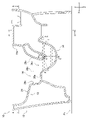
まず、第1実施形態の水洗大便器10の第1の工夫点を説明する。図1は、第1実施形態の水洗大便器10に用いられる便器本体12の斜視図である。図2は、便器本体12の平面図である。図3は、便器本体12の側面断面図である。図4は、図3のA-A線断面図である。
(First Embodiment)
First, the first device of the flush toilet bowl 10 of the first embodiment will be described. FIG. 1 is a perspective view of a toilet bowl body 12 used in the flush toilet bowl 10 of the first embodiment. FIG. 2 is a plan view of the toilet bowl main body 12. FIG. 3 is a side sectional view of the toilet bowl main body 12. FIG. 4 is a cross-sectional view taken along the line AA of FIG.

水洗大便器10は、便器本体12と、洗浄水供給装置14と、を備える。図4に示すように、本実施形態の洗浄水供給装置14は、貯水タンク(不図示)、分配器16等を用いて構成される。 The flush toilet bowl 10 includes a toilet bowl main body 12 and a flush water supply device 14. As shown in FIG. 4, the washing water supply device 14 of the present embodiment is configured by using a water storage tank (not shown), a distributor 16, and the like.

本実施形態の便器本体12は陶器を素材とするが、樹脂等を素材としてもよい。本実施形態の便器本体12は洋風大便器である。本実施形態の便器本体12は、トイレ室の床面Fs(図3参照)上に設置される床置き式である。 The toilet bowl body 12 of the present embodiment is made of pottery, but may be made of resin or the like. The toilet bowl body 12 of this embodiment is a Western-style toilet bowl. The toilet body 12 of the present embodiment is a floor-standing type installed on the floor surface Fs (see FIG. 3) of the toilet room.

以下、水洗大便器10の構成要素の位置関係に関して、互いに直交する三つの方向を用いて説明する。この方向とは、便器本体12の前後方向X、左右方向Y及び上下方向Zである。前後方向X、左右方向Yは水平方向であり、便器本体12に取り付けられる便座(不図示)に通常の姿勢で座る着座者の前後左右と対応する。上下方向Zは鉛直方向である。 Hereinafter, the positional relationship of the components of the flush toilet bowl 10 will be described using three directions orthogonal to each other. This direction is the front-back direction X, the left-right direction Y, and the up-down direction Z of the toilet bowl main body 12. The front-back direction X and the left-right direction Y are horizontal directions, and correspond to the front-back and left-right of a seated person sitting in a normal posture on a toilet seat (not shown) attached to the toilet body 12. The vertical direction Z is the vertical direction.

また、本明細書では、水洗大便器10の構成要素の位置関係に関して、便器本体12の便鉢部18の周方向、径方向を用いて説明する。ここでの「周方向」とは、便器本体12を上方から見て、その便鉢部18の上端内縁部18aの中心Cp(図2参照)周りを回る方向をいう。また、「径方向」とは、その中心Cpを通る鉛直線に直交する方向をいう。 Further, in the present specification, the positional relationship of the components of the flush toilet bowl 10 will be described using the circumferential direction and the radial direction of the toilet bowl portion 18 of the toilet bowl main body 12. Here, the "circumferential direction" refers to a direction in which the toilet bowl body 12 is viewed from above and orbits around the center Cp (see FIG. 2) of the upper end inner edge portion 18a of the toilet bowl portion 18. Further, the "diameter direction" means a direction orthogonal to the vertical straight line passing through the center Cp.

図2、図3を参照する。便器本体12は便鉢部18を有する。便鉢部18の上端内縁部18aは、便器本体12の上面部20に連なり、その上面部20の後部には便座を取り付けるための取付孔22が設けられる。 Refer to FIGS. 2 and 3. The toilet body 12 has a toilet bowl portion 18. The upper end inner edge portion 18a of the toilet bowl portion 18 is connected to the upper surface portion 20 of the toilet bowl main body 12, and a mounting hole 22 for mounting the toilet seat is provided at the rear portion of the upper surface portion 20.

便鉢部18は、汚物を受けるための鉢状の汚物受け面24と、汚物受け面24の下端縁から下方に窪む溜水部26と、を備える。汚物受け面24は、平面視での曲率半径が前端部24aにおいて最小となる形状である。 The toilet bowl portion 18 includes a pot-shaped filth receiving surface 24 for receiving filth, and a water reservoir portion 26 that is recessed downward from the lower end edge of the filth receiving surface 24. The filth receiving surface 24 has a shape in which the radius of curvature in a plan view is minimized at the front end portion 24a.

便鉢部18は、左右一方側となる左側(図2では紙面の右側)の左側方部分18b(第1側方部分)と、左右他方側(図2では紙面の左側)の右側方部分18c(第2側方領域)とを有する。左側方部分18bは、便鉢部18の左右中心線Lcに対して左右一方側に配置される便鉢部18の一部分であり、右側方部分18cは、その左右中心線Lcに対して左右他方側に配置される便鉢部18の一部分である。左右中心線Lcとは平面視において、便鉢部18の内面部分の左右方向Yに沿った寸法を二等分し、前後方向Xに沿って延びる直線をいう。 The toilet bowl portion 18 has a left side portion 18b (first side portion) on the left side (right side of the paper in FIG. 2) and a right side portion 18c on the left and right other sides (left side of the paper surface in FIG. 2). (Second side area). The left side portion 18b is a part of the toilet bowl portion 18 arranged on one of the left and right sides with respect to the left and right center line Lc of the toilet bowl portion 18, and the right side portion 18c is the left and right other side with respect to the left and right center line Lc. It is a part of the toilet bowl portion 18 arranged on the side. The left-right center line Lc is a straight line that bisects the dimension of the inner surface portion of the toilet bowl portion 18 along the left-right direction Y and extends along the front-back direction X in a plan view.

図4に示すように、便器本体12は、便鉢部18内に洗浄水を吐き出すための吐水部28A、28Bを備える。吐水部28A、28Bには、便鉢部18の右側方部分18cに形成される第1吐水孔30Aを有する第1吐水部28Aと、便鉢部18の左側方部分18bに形成される第2吐水孔30Bを有する第2吐水部28Bとが含まれる。本実施形態の第1吐水孔30Aや第2吐水孔30Bは、溜水部26より後方にて便鉢部18の後部に形成される。本実施形態の第1吐水孔30Aは、溜水部26より左右他方側となる右側に形成され、本実施形態の第2吐水孔30Bは、溜水部26より左右一方側となる左側に形成される。 As shown in FIG. 4, the toilet bowl main body 12 includes water discharge portions 28A and 28B for discharging wash water into the toilet bowl portion 18. The water discharge portions 28A and 28B have a first water discharge portion 28A having a first water discharge hole 30A formed in the right side portion 18c of the toilet bowl portion 18 and a second water discharge portion 28A formed in the left side portion 18b of the toilet bowl portion 18. A second spouting portion 28B having a spouting hole 30B is included. The first water discharge hole 30A and the second water discharge hole 30B of the present embodiment are formed behind the water reservoir portion 26 and behind the toilet bowl portion 18. The first water discharge hole 30A of the present embodiment is formed on the right side on the left and right sides of the water reservoir 26, and the second water discharge hole 30B of the present embodiment is formed on the left side on the left and right sides of the water reservoir 26. Will be done.

第1吐水孔30Aは前方に向けて開放しており、便鉢部18内に周方向の一方側(図9の紙面では反時計回り方向。以下、単に反時計回り方向ともいう)に洗浄水を吐き出す。第2吐水孔30Bは、左右他方側となる右側に向けて開放しており、便鉢部18内に反時計回り方向に洗浄水を吐き出す。 The first water discharge hole 30A is open toward the front, and the washing water is flushed in the toilet bowl portion 18 on one side in the circumferential direction (counterclockwise on the paper in FIG. 9, hereinafter simply referred to as counterclockwise). Spit out. The second water discharge hole 30B is open toward the right side, which is the other side of the left and right sides, and discharges the washing water into the toilet bowl portion 18 in the counterclockwise direction.

第1吐水部28Aは、第1吐水孔30Aに洗浄水を供給するための第1通水路32Aを有する。第2吐水部28Bは、第2吐水孔30Bに洗浄水を供給するための第2通水路32Bを有する。第1通水路32Aは便器本体12の右側の側方部分に設けられ、第2通水路32Bは便器本体12の左側の側方部分に設けられる。第1通水路32Aや第2通水路32Bには、洗浄水供給装置14から洗浄水が供給される。 The first water discharge unit 28A has a first water passage 32A for supplying wash water to the first water discharge hole 30A. The second water discharge unit 28B has a second water passage 32B for supplying wash water to the second water discharge hole 30B. The first water passage 32A is provided in the right side portion of the toilet body 12, and the second water passage 32B is provided in the left side portion of the toilet body 12. Washing water is supplied from the washing water supply device 14 to the first water passage 32A and the second water passage 32B.

図5は、図2のB-B線断面の一部を示す図である。図6は、図5のC-C線端面の一部を主に示す図である。便鉢部18は、便鉢部18の上端内縁部18aから垂下する垂下壁部34を有する。垂下壁部34の内周面は便鉢部18の上端内縁部18aから汚物受け面24の外周端部24bまで下方に連続している。垂下壁部34の内周面には、便鉢部18の上端内縁部18aから汚物受け面24の外周端部24bまでの範囲で水平面が設けられていないということである。これにより、垂下壁部34の内周面に水平面が設けられる場合と比べ、垂下壁部34の内周面を拭き易くなる。 FIG. 5 is a diagram showing a part of the cross section taken along the line BB of FIG. FIG. 6 is a diagram mainly showing a part of the end face of the CC line of FIG. The toilet bowl portion 18 has a hanging wall portion 34 that hangs down from the upper end inner edge portion 18a of the toilet bowl portion 18. The inner peripheral surface of the hanging wall portion 34 is continuous downward from the upper end inner edge portion 18a of the toilet bowl portion 18 to the outer peripheral end portion 24b of the filth receiving surface 24. The inner peripheral surface of the hanging wall portion 34 is not provided with a horizontal plane in the range from the upper end inner edge portion 18a of the toilet bowl portion 18 to the outer peripheral end portion 24b of the filth receiving surface 24. This makes it easier to wipe the inner peripheral surface of the hanging wall portion 34 as compared with the case where the horizontal surface is provided on the inner peripheral surface of the hanging wall portion 34.

垂下壁部34の内周面は、本実施形態において、上端内縁部18aから下方に向かうにつれて径方向内側に延びるように形成される。この他にも、垂下壁部34の内周面は、上端内縁部18aから下方に向かうにつれて径方向外側に延びるようなオーバーハング形状に形成されてもよい。 In the present embodiment, the inner peripheral surface of the hanging wall portion 34 is formed so as to extend radially inward from the upper end inner edge portion 18a toward the lower side. In addition to this, the inner peripheral surface of the hanging wall portion 34 may be formed in an overhang shape so as to extend radially outward from the upper end inner edge portion 18a toward the lower side.

本実施形態の垂下壁部34は、図1に示すように、便鉢部18の全周に亘る範囲に設けられる。本実施形態の垂下壁部34の内周面は、略全周に亘る範囲において、吐水孔30A、30B以外の箇所で、滑らかに連なっている。垂下壁部34は、便鉢部18の周方向の全周に亘る範囲のうち周方向の半分以上の範囲に少なくとも設けられていてもよい。この他にも、垂下壁部34は、便鉢部18の周方向の全周に亘る範囲のうち周方向の大部分の範囲に少なくとも設けられていてもよい。ここでの大部分とは、たとえば、便鉢部18の周方向の全周に亘る範囲のうち80%以上の範囲をいう。 As shown in FIG. 1, the hanging wall portion 34 of the present embodiment is provided over the entire circumference of the toilet bowl portion 18. The inner peripheral surface of the hanging wall portion 34 of the present embodiment is smoothly connected at locations other than the water discharge holes 30A and 30B in a range covering substantially the entire circumference. The hanging wall portion 34 may be provided at least in a range of at least half of the circumferential direction of the toilet bowl portion 18 over the entire circumferential direction. In addition to this, the hanging wall portion 34 may be provided at least in a large part of the circumferential direction of the entire circumference of the toilet bowl portion 18 in the circumferential direction. The majority here means, for example, a range of 80% or more of the entire circumference of the toilet bowl portion 18 in the circumferential direction.

以下、第1吐水部28Aと第2吐水部28Bは多くの構成が共通するため、その共通する構成に関して第1吐水部28Aを示す図面を参照しながら説明する。図5、図6を参照する。第1吐水部28Aの第1吐水孔30Aは垂下壁部34を貫通している。第1吐水孔30Aの内下面30aは、第1通水路32Aの内下面32aと、便鉢部18の内面としての汚物受け面24とを滑らかに連ねている。本明細書での「滑らかに」とは、言及している面にでこぼこや段差がなく、すべすべしているさまをいう。第1吐水孔30Aの内上面30bは、第1通水路32Aの内上面32bより下方に設けられる。 Hereinafter, since the first water discharge unit 28A and the second water discharge unit 28B have many configurations in common, the common configuration will be described with reference to the drawings showing the first water discharge unit 28A. See FIGS. 5 and 6. The first water discharge hole 30A of the first water discharge portion 28A penetrates the hanging wall portion 34. The inner lower surface 30a of the first water discharge hole 30A smoothly connects the inner lower surface 32a of the first water passage 32A and the filth receiving surface 24 as the inner surface of the toilet bowl portion 18. The term "smoothly" as used herein means that the surface referred to is smooth without any irregularities or steps. The inner upper surface 30b of the first water discharge hole 30A is provided below the inner upper surface 32b of the first water passage 32A.

垂下壁部34は、第1吐水孔30Aを形成するとともに第1吐水孔30Aより上方に設けられる第1孔形成部36Aを有する。第1孔形成部36Aの内周面は、便鉢部18の上端内縁部18aから第1吐水孔30Aまでの範囲で滑らかに連なっている。第1孔形成部36Aの内周面は、第1孔形成部36Aと周方向両側に隣接する垂下壁部34の他部分の内周面と滑らかに連なっている。 The hanging wall portion 34 has a first spouting hole 30A and a first hole forming portion 36A provided above the first spouting hole 30A. The inner peripheral surface of the first hole forming portion 36A is smoothly connected in the range from the upper end inner edge portion 18a of the toilet bowl portion 18 to the first water discharge hole 30A. The inner peripheral surface of the first hole forming portion 36A is smoothly connected to the inner peripheral surface of the first hole forming portion 36A and the other portion of the hanging wall portion 34 adjacent to both sides in the circumferential direction.

これにより、第1吐水孔30Aを形成する垂下壁部34の第1孔形成部36Aの内周面が便鉢部18の上端内縁部18aに滑らかに連なった箇所に設けられる。よって、便鉢部18の上端内縁部18aから奥まった箇所に第1吐水孔30Aを形成する壁部が配置される場合と比べ、便鉢部18の上端内縁部18aとともに垂下壁部34の第1孔形成部36Aの内周面を拭き易くなり、良好な清掃性を得られる。 As a result, the inner peripheral surface of the first hole forming portion 36A of the hanging wall portion 34 forming the first water discharge hole 30A is provided at a position where the inner peripheral surface of the first hole forming portion 36A is smoothly connected to the upper end inner edge portion 18a of the toilet bowl portion 18. Therefore, as compared with the case where the wall portion forming the first water discharge hole 30A is arranged at a position deep from the upper end inner edge portion 18a of the toilet bowl portion 18, the hanging wall portion 34 together with the upper end inner edge portion 18a of the toilet bowl portion 18 The inner peripheral surface of the 1-hole forming portion 36A can be easily wiped, and good cleanability can be obtained.

また、便鉢部18の上端内縁部18aが第1吐水孔30Aを形成する場合と比べ、第1吐水孔30Aの大きさが小さくなり、良好な意匠性を得られる。また、便鉢部18の上端内縁部18aが第1吐水孔30Aを形成する場合と比べ、第1吐水孔30Aから吐き出された洗浄水が上端内縁部18aを伝って、便器本体12の上面部20まで伝う事態を避け易くなる。また、便鉢部18の上端内縁部18aが第1吐水孔30Aを形成する場合と比べ、便鉢部18内を流れる洗浄水の高さを抑えられ、洗浄水の飛沫が便鉢部18の外部に飛散する事態を避け易くなる。 Further, the size of the first water discharge hole 30A is smaller than that in the case where the upper end inner edge portion 18a of the toilet bowl portion 18 forms the first water discharge hole 30A, and good designability can be obtained. Further, as compared with the case where the upper end inner edge portion 18a of the toilet bowl portion 18 forms the first water discharge hole 30A, the washing water discharged from the first water discharge hole 30A is transmitted through the upper end inner edge portion 18a and the upper surface portion of the toilet bowl main body 12. It becomes easier to avoid the situation that is transmitted up to 20. Further, as compared with the case where the upper end inner edge portion 18a of the toilet bowl portion 18 forms the first water discharge hole 30A, the height of the washing water flowing in the toilet bowl portion 18 can be suppressed, and the splash of the washing water of the toilet bowl portion 18 can be suppressed. It becomes easier to avoid the situation of scattering to the outside.

以上の効果を得る観点からは、次の条件を満たすと好ましい。垂下壁部34の第1孔形成部36Aの高さHaは、便鉢部18の上端内縁部18aの上端から第1吐水孔30Aの内上面30bまでの高さで定義される。また、便鉢部18の上端内縁部18aの上端から第1吐水孔30Aの内下面30aまでの高さをHbという。このとき、垂下壁部34の第1孔形成部36Aの高さHaは、高さHbの半分以上の大きさに設定されると好ましい。この条件は、本発明者による実験的な検討に基づき導き出したものである。これにより、垂下壁部34の第1孔形成部36Aの内周面が拭き掃除するうえで適度な大きさとなり、その内周面をより拭き易くなり、より良好な清掃性を得られる。 From the viewpoint of obtaining the above effects, it is preferable to satisfy the following conditions. The height Ha of the first hole forming portion 36A of the hanging wall portion 34 is defined by the height from the upper end of the upper end inner edge portion 18a of the toilet bowl portion 18 to the inner upper surface 30b of the first water discharge hole 30A. Further, the height from the upper end of the upper end inner edge portion 18a of the toilet bowl portion 18 to the inner lower surface 30a of the first water discharge hole 30A is referred to as Hb. At this time, it is preferable that the height Ha of the first hole forming portion 36A of the hanging wall portion 34 is set to a size equal to or more than half of the height Hb. This condition was derived based on an experimental study by the present inventor. As a result, the inner peripheral surface of the first hole forming portion 36A of the hanging wall portion 34 becomes an appropriate size for wiping and cleaning, and the inner peripheral surface thereof becomes easier to wipe, and better cleaning performance can be obtained.

また、第1吐水孔30Aの大きさが小さくなり、より良好な意匠性を得られる。また、第1吐水孔30Aから吐き出された洗浄水が上端内縁部18aまで伝わり難くなり、その洗浄水が便器本体12の上面部20まで伝う事態をより避け易くなる。また、便鉢部18内を流れる洗浄水の高さをより抑えられ、洗浄水の飛沫が便鉢部18の外部に飛散する事態をより避け易くなる。 In addition, the size of the first water discharge hole 30A becomes smaller, and better design can be obtained. Further, it becomes difficult for the washing water discharged from the first water discharge hole 30A to be transmitted to the upper end inner edge portion 18a, and it becomes easier to avoid the situation where the washing water is transmitted to the upper surface portion 20 of the toilet bowl main body 12. Further, the height of the washing water flowing in the toilet bowl portion 18 can be further suppressed, and it becomes easier to avoid the situation where the washing water droplets are scattered to the outside of the toilet bowl portion 18.

また、第1吐水孔30Aの内下面30aは、第1通水路32Aの内下面32aと、便鉢部18の内面としての汚物受け面24とを滑らかに連ねている。よって、第1通水路32A内の水が、第1通水路32A内にとどまることなく、第1吐水孔30Aの内下面30aを伝って便鉢部18内に流れ易くなり、良好な衛生性を得られる。 Further, the inner lower surface 30a of the first water discharge hole 30A smoothly connects the inner lower surface 32a of the first water passage 32A and the filth receiving surface 24 as the inner surface of the toilet bowl portion 18. Therefore, the water in the first water passage 32A does not stay in the first water passage 32A, but easily flows through the inner lower surface 30a of the first water discharge hole 30A into the toilet bowl portion 18, and has good hygiene. can get.

ここまで第1吐水部28Aに関して詳細に説明したが、第2吐水部28Bでも多くの点で共通する。つまり、第2吐水部28Bの第2吐水孔30Bも垂下壁部34を貫通している。図示はしないが、第2吐水孔30Bの内下面も、第2通水路32Bの内下面と、便鉢部18の汚物受け面24とを滑らかに連ねている。垂下壁部34は、第2吐水孔30Bを形成するとともに第2吐水孔30Bより上方に設けられる第2孔形成部36Bを有する。第2孔形成部36Bは第1孔形成部36Aと同様の構成になるため、その説明を省略する。 Although the first water discharge unit 28A has been described in detail so far, the second water discharge unit 28B is also common in many respects. That is, the second water discharge hole 30B of the second water discharge portion 28B also penetrates the hanging wall portion 34. Although not shown, the inner and lower surfaces of the second water discharge hole 30B also smoothly connects the inner and lower surfaces of the second water passage 32B and the sewage receiving surface 24 of the toilet bowl portion 18. The hanging wall portion 34 has a second spouting hole 30B and a second hole forming portion 36B provided above the second spouting hole 30B. Since the second hole forming portion 36B has the same configuration as the first hole forming portion 36A, the description thereof will be omitted.

次に、水洗大便器10の他の特徴を説明する。図7は、便器本体12の分解斜視図である。図1、図5、図7に示すように、本実施形態の便器本体12は、上面側部分38A、38Bと、上面側部分38A、38Bより下側の便鉢側部分40とを接合して構成される。上面側部分38A、38Bと便鉢側部分40とは接着等により接合される。上面側部分38A、38Bと便鉢側部分40は、陶器製の便器本体12を得るために必要な便器本体12の半製品であり、鋳込み成形により得られる鋳込み成形品である。本実施形態の便器本体12は、未焼成状態にある鋳込み成形品としての上面側部分38A、38Bと便鉢側部分40を接合した後、それらを焼成することで得られる。 Next, other features of the flush toilet 10 will be described. FIG. 7 is an exploded perspective view of the toilet bowl main body 12. As shown in FIGS. 1, 5, and 7, in the toilet bowl main body 12 of the present embodiment, the upper surface side portions 38A and 38B and the toilet bowl side portion 40 below the upper surface side portions 38A and 38B are joined. It is composed. The upper surface side portions 38A and 38B and the toilet bowl side portion 40 are joined by adhesion or the like. The upper surface side portions 38A and 38B and the toilet bowl side portion 40 are semi-finished products of the toilet bowl main body 12 necessary for obtaining the toilet bowl main body 12 made of pottery, and are cast-molded products obtained by casting molding. The toilet bowl main body 12 of the present embodiment is obtained by joining the upper surface side portions 38A and 38B as cast molded products in an unfired state and the toilet bowl side portion 40, and then firing them.

上面側部分38A、38Bと便鉢側部分40は、便器本体12を分割した形状を持つ。上面側部分38A、38Bは、便器本体12の上面部20の少なくとも一部を含む部分である。本実施形態の上面側部分38A、38Bには、第1吐水部28Aに対応する第1上面側部分38Aと、第2吐水部28Bに対応する第2上面側部分38Bとが含まれる。便鉢側部分40は、便器本体12の上面側部分38A、38Bより下側の部分であり、便鉢部18の大部分を含む部分である。以下、第1上面側部分38Aと第2上面側部分38Bは多くの構成が共通するため、その共通する構成に関して第1上面側部分38Aを示す図面を参照しながら説明する。 The upper surface side portions 38A and 38B and the toilet bowl side portion 40 have a shape in which the toilet bowl main body 12 is divided. The upper surface side portions 38A and 38B are portions including at least a part of the upper surface portion 20 of the toilet bowl main body 12. The upper surface side portions 38A and 38B of the present embodiment include a first upper surface side portion 38A corresponding to the first water discharge portion 28A and a second upper surface side portion 38B corresponding to the second water discharge portion 28B. The toilet bowl side portion 40 is a portion below the upper surface side portions 38A and 38B of the toilet bowl body 12, and is a portion including most of the toilet bowl portion 18. Hereinafter, since the first upper surface side portion 38A and the second upper surface side portion 38B have many configurations in common, the common configuration will be described with reference to the drawing showing the first upper surface side portion 38A.

図8は、図3のD-D線断面図である。図5、図8に示すように、上面側部分38A、38Bと便鉢側部分40の境界位置は、上面側部分38A、38Bに対応する吐水部28A、28Bを形成する壁部を上下に分割する位置に設定される。図5等では、説明の便宜のため、上面側部分38A、38Bと便鉢側部分40との境界位置を二点鎖線で示すが、これらは外観に現われなくともよい。便鉢側部分40の吐水孔30A、30Bや通水路32A、32Bを形成する箇所は上側に開放した形状となる。上面側部分38A、38Bは、便鉢側部分40の吐水孔30A、30Bや通水路32A、32Bを形成する箇所を上側から塞ぐように配置される。 FIG. 8 is a sectional view taken along line DD of FIG. As shown in FIGS. 5 and 8, the boundary position between the upper surface side portions 38A and 38B and the toilet bowl side portion 40 divides the wall portion forming the water discharge portions 28A and 28B corresponding to the upper surface side portions 38A and 38B into upper and lower parts. It is set to the position to be. In FIG. 5 and the like, for convenience of explanation, the boundary position between the upper surface side portions 38A and 38B and the toilet bowl side portion 40 is shown by a two-dot chain line, but these do not have to appear in the appearance. The portions forming the water discharge holes 30A and 30B and the water passages 32A and 32B of the toilet bowl side portion 40 have a shape that is open to the upper side. The upper surface side portions 38A and 38B are arranged so as to close the water discharge holes 30A and 30B of the toilet bowl side portion 40 and the portions forming the water passages 32A and 32B from the upper side.

図5、図7、図8に示すように、第1上面側部分38Aは、第1通水路32Aの内上面32bを構成する第1上壁部42Aと、垂下壁部34の第1孔形成部36Aを少なくとも構成する第1垂下側壁部44Aとを有する。第1上壁部42Aは、便器本体12の上面部20の一部を構成する。第1垂下側壁部44Aは、第1吐水孔30Aの内上面30bを構成する。第1垂下側壁部44Aの両側部44aは、第1孔形成部36Aと周方向両側に隣接する垂下壁部34の他部分を構成する。 As shown in FIGS. 5, 7, and 8, the first upper surface side portion 38A has a first upper wall portion 42A constituting the inner upper surface portion 32b of the first water passage 32A and a first hole formation of the hanging wall portion 34. It has at least a first hanging side wall portion 44A constituting the portion 36A. The first upper wall portion 42A constitutes a part of the upper surface portion 20 of the toilet bowl main body 12. The first hanging side wall portion 44A constitutes the inner upper surface 30b of the first water discharge hole 30A. Both side portions 44a of the first hanging side wall portion 44A constitute the first hole forming portion 36A and other parts of the hanging wall portion 34 adjacent to both sides in the circumferential direction.

便鉢側部分40は、第1通水路32Aの内側面32cを構成する一対の第1側壁部46Aと、第1通水路32Aの内下面32aを構成する第1下壁部48Aとを有する。一対の第1側壁部46Aは、第1吐水孔30Aを形成する入側開口部50を有する。第1下壁部48Aは第1吐水孔30Aの内下面30aも構成する。 The toilet bowl side portion 40 has a pair of first side wall portions 46A constituting the inner side surface 32c of the first water passage 32A, and a first lower wall portion 48A constituting the inner lower surface 32a of the first water passage 32A. The pair of first side wall portions 46A has an entry side opening 50 forming the first water discharge hole 30A. The first lower wall portion 48A also constitutes the inner lower surface 30a of the first water discharge hole 30A.

図9は、図5のE-E線断面の一部を示す図である。図7~図9に示すように、第1側壁部46Aは、第1段部52と、第1段部52の上面52aより低位置に形成される第2段部54とを有する。第2段部54は、第1側壁部46Aの入側開口部50に形成される。第1段部52の上面52aや第2段部54の上面54aは汚物受け面24の外周端部24bより高位置に形成される。第1段部52と第2段部54のそれぞれは、便器本体12の上面部20より低位置に形成される。 FIG. 9 is a diagram showing a part of the cross section taken along the line EE of FIG. As shown in FIGS. 7 to 9, the first side wall portion 46A has a first step portion 52 and a second step portion 54 formed at a position lower than the upper surface 52a of the first step portion 52. The second step portion 54 is formed in the entrance side opening 50 of the first side wall portion 46A. The upper surface 52a of the first stage portion 52 and the upper surface 54a of the second stage portion 54 are formed at positions higher than the outer peripheral end portion 24b of the filth receiving surface 24. Each of the first stage portion 52 and the second stage portion 54 is formed at a position lower than the upper surface portion 20 of the toilet bowl main body 12.

第1段部52の上面52aは、第1上面側部分38Aの第1上壁部42Aの側端部と接触して第1上壁部42Aを支持する。第2段部54の上面54aは、第1上面側部分38Aの第1垂下側壁部44Aの両側部と接触して第1垂下側壁部44Aを支持する。 The upper surface 52a of the first step portion 52 comes into contact with the side end portion of the first upper wall portion 42A of the first upper surface side portion 38A to support the first upper wall portion 42A. The upper surface 54a of the second step portion 54 comes into contact with both side portions of the first hanging side wall portion 44A of the first upper surface side portion 38A to support the first hanging side wall portion 44A.

第2段部54は、第2段部54の上面54aから立ち上がる側面54bを有する。第2段部54は、第1通水路32Aの内側面や垂下壁部34の内周面から水平方向に凹むように形成される。第2段部54の側面54bには、第1垂下側壁部44Aの両側部が接触している。 The second step portion 54 has a side surface 54b that rises from the upper surface 54a of the second step portion 54. The second step portion 54 is formed so as to be recessed in the horizontal direction from the inner side surface of the first water passage 32A and the inner peripheral surface of the hanging wall portion 34. Both sides of the first hanging side wall portion 44A are in contact with the side surface 54b of the second step portion 54.

以上の水洗大便器10の効果を説明する。かりに、便鉢側部分40と接触していない場合、第1上面側部分38Aの第1垂下側壁部44Aは、その第1上壁部42Aからぶら下がった状態となる。よって、第1上面側部分38Aの第1垂下側壁部44Aは、未焼成状態にあるときに自重により下向きの力成分が付与され、下向きに伸びる恐れがある。 The effect of the above-mentioned flush toilet bowl 10 will be described. When not in contact with the toilet bowl side portion 40, the first hanging side wall portion 44A of the first upper surface side portion 38A is in a state of hanging from the first upper wall portion 42A. Therefore, when the first hanging side wall portion 44A of the first upper surface side portion 38A is in the unfired state, a downward force component is applied by its own weight, and there is a possibility that the first hanging side wall portion 44A extends downward.

この点、本実施形態によれば、便鉢側部分40は、第1上面側部分38Aの第1垂下側壁部44Aと接触して第1垂下側壁部44Aを支持している。よって、第1上面側部分38Aの第1垂下側壁部44Aに付与される自重による下向きの力成分を便鉢側部分40に伝達できる。この結果、未焼成状態にあるとき、第1上面側部分38Aの第1垂下側壁部44Aに作用する下向きの力成分を低減でき、その第1垂下側壁部44Aが伸びてしまう事態を避けられる。これに伴い、第1上面側部分38Aの第1垂下側壁部44Aにより目的とする形状の第1吐水孔30Aを精度よく得やすくなる。 In this respect, according to the present embodiment, the toilet bowl side portion 40 is in contact with the first hanging side wall portion 44A of the first upper surface side portion 38A and supports the first hanging side wall portion 44A. Therefore, the downward force component due to its own weight applied to the first hanging side wall portion 44A of the first upper surface side portion 38A can be transmitted to the toilet bowl side portion 40. As a result, when it is in the unfired state, the downward force component acting on the first hanging side wall portion 44A of the first upper surface side portion 38A can be reduced, and the situation where the first hanging side wall portion 44A is stretched can be avoided. Along with this, the first hanging side wall portion 44A of the first upper surface side portion 38A makes it easier to accurately obtain the first water discharge hole 30A having the desired shape.

また、第1上面側部分38Aの第1垂下側壁部44Aは、第2段部54の側面54bと接触している。よって、便鉢側部分40に第1上面側部分38Aを接合する際、第1上面側部分38Aの第1垂下側壁部44Aと第2段部54の側面54bとの接触によって、便鉢側部分40に対する水平方向での第1上面側部分38Aの相対移動を規制できる。これに伴い、便鉢側部分40に対する第1上面側部分38Aの位置決め作業が容易になる。 Further, the first hanging side wall portion 44A of the first upper surface side portion 38A is in contact with the side surface 54b of the second step portion 54. Therefore, when the first upper surface side portion 38A is joined to the toilet bowl side portion 40, the contact between the first hanging side wall portion 44A of the first upper surface side portion 38A and the side surface 54b of the second step portion 54 causes the toilet bowl side portion. The relative movement of the first upper surface side portion 38A in the horizontal direction with respect to 40 can be restricted. Along with this, the positioning work of the first upper surface side portion 38A with respect to the toilet bowl side portion 40 becomes easy.

なお、この他にも、第1上面側部分38Aの第1上壁部42Aと第1段部52の側面52b(図7、図8参照)との接触によっても、便鉢側部分40に対する水平方向での第1上面側部分38Aの相対移動を規制できる。 In addition to this, the contact between the first upper wall portion 42A of the first upper surface side portion 38A and the side surface 52b (see FIGS. 7 and 8) of the first step portion 52 is also horizontal to the toilet bowl side portion 40. The relative movement of the first upper surface side portion 38A in the direction can be restricted.

便器本体12を製造する方法として、鋳込み成形により得られる単数の鋳込み成形品により便器本体12を構成し、その鋳込み成形品の一部を切除して吐水孔30A、30Bを形成する手法がある。このような手法を採る場合、鋳込み成形品の一部の切除に伴いバリが発生してしまい、目的とする形状の吐水孔30A、30Bを精度よく形成できないという問題がある。 As a method for manufacturing the toilet bowl main body 12, there is a method in which the toilet bowl main body 12 is formed of a single cast-molded product obtained by cast molding, and a part of the cast-molded product is cut off to form water discharge holes 30A and 30B. When such a method is adopted, there is a problem that burrs are generated due to the excision of a part of the cast molded product, and the water discharge holes 30A and 30B having the desired shape cannot be formed accurately.

この点、本実施形態のように、上面側部分38A、38Bと便鉢側部分40により便器本体12を構成する場合、上面側部分38A、38Bと便鉢側部分40により吐水孔30A、30Bを形成できる。よって、鋳込み成形品の一部の切除を伴い吐水孔30A、30Bを形成する手法と比べ、目的とする形状の吐水孔30A、30Bを精度よく形成できる利点がある。また、この他にも、単数の鋳込み成形品により便器本体12を構成する場合と比べ、便器本体12の通水路32A、32Bの高さを容易に小さくできる。これに伴い、吐水孔30A、30Bから洗浄水を吐き出すために通水路32A、32B内に供給すべき水量を低減できる利点もある。 In this respect, when the toilet bowl main body 12 is composed of the upper surface side portions 38A and 38B and the toilet bowl side portion 40 as in the present embodiment, the water discharge holes 30A and 30B are formed by the upper surface side portions 38A and 38B and the toilet bowl side portion 40. Can be formed. Therefore, there is an advantage that the water discharge holes 30A and 30B having the desired shape can be formed accurately as compared with the method of forming the water discharge holes 30A and 30B by cutting a part of the cast molded product. In addition to this, the heights of the water passages 32A and 32B of the toilet bowl body 12 can be easily reduced as compared with the case where the toilet bowl main body 12 is configured by a single cast molded product. Along with this, there is also an advantage that the amount of water to be supplied into the water passages 32A and 32B in order to discharge the washing water from the water discharge holes 30A and 30B can be reduced.

ここまで第1上面側部分38Aに関する構成の詳細を説明したが、第2上面側部分38Bでも多くの点で共通する。つまり、第2上面側部分38Bは、第2通水路32Bの内上面を構成する第2上壁部42Bと、垂下壁部34の第2孔形成部36Bを少なくとも構成する第2垂下側壁部44Bと、を有する。 Although the details of the configuration relating to the first upper surface side portion 38A have been described so far, the second upper surface side portion 38B is also common in many respects. That is, the second upper surface side portion 38B has a second upper wall portion 42B constituting the inner upper surface of the second water passage 32B and a second hanging side wall portion 44B constituting at least the second hole forming portion 36B of the hanging wall portion 34. And have.

便鉢側部分40は、第2通水路32Bの内側面32cを構成する一対の第2側壁部46Bと、第2通水路32Bの内下面32aを構成する第2下壁部48Bとを有する。第2側壁部46Bも、第1側壁部46Aと同様、第1段部52と第2段部54を有する。第1段部52の上面は、図示しないが、第2上面側部分38Bの第2垂下側壁部44Bと接触して第2垂下側壁部44Bを支持する。第2段部54の上面は、図示しないが、第2上面側部分38Bの第2垂下側壁部44Bと接触して第2垂下側壁部44Bを支持する。 The toilet bowl side portion 40 has a pair of second side wall portions 46B constituting the inner side surface 32c of the second water passage 32B, and a second lower wall portion 48B constituting the inner lower surface 32a of the second water passage 32B. The second side wall portion 46B also has a first step portion 52 and a second step portion 54, similarly to the first side wall portion 46A. Although not shown, the upper surface of the first step portion 52 comes into contact with the second hanging side wall portion 44B of the second upper surface side portion 38B to support the second hanging side wall portion 44B. Although not shown, the upper surface of the second step portion 54 comes into contact with the second hanging side wall portion 44B of the second upper surface side portion 38B to support the second hanging side wall portion 44B.

次に水洗大便器10の第2の工夫点を説明する。図2、図3を参照する。便器本体12は、便鉢部18の他に、便鉢部18の底部に接続される便器排水路56を備える。便器排水路56は、便鉢部18内から下水側水路(不図示)に排出される汚物や水の通り道となる。 Next, the second device of the flush toilet bowl 10 will be described. Refer to FIGS. 2 and 3. In addition to the toilet bowl portion 18, the toilet bowl main body 12 includes a toilet bowl drainage channel 56 connected to the bottom of the toilet bowl portion 18. The toilet drainage channel 56 serves as a passage for filth and water discharged from the toilet bowl portion 18 to the sewage side water channel (not shown).

溜水部26は、便鉢部18の底部を形成するとともに有底状をなす。溜水部26は、底壁面26aと、底壁面26aから立ち上がる複数の立壁面26b~26dと、を有する。底壁面26aの後部には便器排水路56の入口56aが開口する。溜水部26には溜水が溜められる。 The water reservoir portion 26 forms the bottom portion of the toilet bowl portion 18 and has a bottomed shape. The water reservoir portion 26 has a bottom wall surface 26a and a plurality of vertical wall surfaces 26b to 26d rising from the bottom wall surface 26a. The entrance 56a of the toilet drainage channel 56 opens at the rear of the bottom wall surface 26a. Reservoir is stored in the reservoir 26.

立壁面26b~26dには、溜水部26の左右一方側となる左側(図2の紙面では右側)に設けられる左側立壁面26b(第1立壁面)と、溜水部26の左右他方側となる右側(図2の紙面では左側)に設けられる右側立壁面26c(第2立壁部)とが含まれる。また、立壁面26b~26dには、溜水部26の後側に設けられる後側立壁面26dが含まれる。左側立壁面26bと右側立壁面26cは、後述する誘導流Fwf(図15参照)を形成するため、前方に向かうにつれて先細りする形状であり、その前端部が第1凹曲面26eを介して滑らかに連なっている。本実施形態の左側立壁面26bは、第2凹曲面26fを介して後側立壁面26dに滑らかに連なっている。本実施形態の右側立壁面26cは、第3凹曲面26gを介して後側立壁面26dに滑らかに連なっている。 On the standing walls 26b to 26d, the left standing wall 26b (first standing wall) provided on the left side (right side in the paper in FIG. 2) on the left and right sides of the water reservoir 26 and the left and right other sides of the water reservoir 26. The right side standing wall surface 26c (second standing wall portion) provided on the right side (left side in the paper of FIG. 2) is included. Further, the standing wall surfaces 26b to 26d include a rear side standing wall surface 26d provided on the rear side of the water reservoir portion 26. The left side standing wall surface 26b and the right side standing wall surface 26c have a shape that tapers toward the front in order to form a guided flow Fwf (see FIG. 15) described later, and the front end portions thereof are smoothly interposed through the first concave curved surface 26e. It is connected. The left side standing wall surface 26b of the present embodiment is smoothly connected to the rear side standing wall surface 26d via the second concave curved surface 26f. The right side standing wall surface 26c of the present embodiment is smoothly connected to the rear side standing wall surface 26d via the third concave curved surface 26g.

図10は、便器本体12の他の平面図である。汚物受け面24は、平面視において、溜水部26と前後方向Xに重なり溜水部26より後方に設けられる後側領域60と、溜水部26及び後側領域60と左右方向Yに重なる一対の横側領域62A、62Bとを有する。また、汚物受け面24は、平面視において、溜水部26や横側領域62A、62Bと前後方向Xに重なり溜水部26より前方に設けられる前側領域64を有する。 
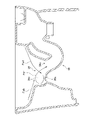
FIG. 10 is another plan view of the toilet bowl body 12. In a plan view, the filth receiving surface 24 overlaps the water reservoir 26 in the front-rear direction X and overlaps the rear side region 60 provided behind the water storage part 26 and the water storage part 26 and the rear side area 60 in the left-right direction Y. It has a pair of lateral regions 62A, 62B. Further, the filth receiving surface 24 has a front side region 64 which overlaps with the water storage portion 26 and the lateral regions 62A and 62B in the front-rear direction X and is provided in front of the water storage portion 26 in a plan view.

図11は、便器本体12の更に他の平面図である。便鉢部18は、吐水孔30A、30Bから吐き出された洗浄水を便鉢部18の内周面に沿って旋回させるように導くための棚面66を有する。本実施形態の棚面66は、第1吐水孔30Aの内下面に連なるように形成され、かつ、第2吐水孔30Bの内下面に連なるように形成される。 FIG. 11 is still another plan view of the toilet bowl body 12. The toilet bowl portion 18 has a shelf surface 66 for guiding the washing water discharged from the water discharge holes 30A and 30B so as to swirl along the inner peripheral surface of the toilet bowl portion 18. The shelf surface 66 of the present embodiment is formed so as to be connected to the inner and lower surfaces of the first water discharge hole 30A and to be connected to the inner and lower surfaces of the second water discharge hole 30B.

図12は、図3の一部の拡大図である。図13は、図2のB-B線端面の一部を主に示す図である。図11~図13に示すように、棚面66は、汚物受け面24の外周端部24bから径方向内側に向かう範囲の一部が構成している。棚面66は、便鉢部18の径方向に沿った切断面での形状が平坦面である。図12、図13では、このような径方向に沿った切断面の形状を示す。 FIG. 12 is an enlarged view of a part of FIG. FIG. 13 is a diagram mainly showing a part of the end face of the BB line of FIG. As shown in FIGS. 11 to 13, the shelf surface 66 constitutes a part of a range extending inward in the radial direction from the outer peripheral end portion 24b of the dirt receiving surface 24. The shape of the shelf surface 66 as a cut surface along the radial direction of the toilet bowl portion 18 is a flat surface. 12 and 13 show the shape of the cut surface along the radial direction.

棚面66は、汚物受け面24の後側領域60から横側領域62A、62Bにかけて連続するように形成される。本実施形態の棚面66は、汚物受け面24の後側領域60から一対の横側領域62A、62Bのそれぞれにかけて連続するように形成される。本実施形態の棚面66は、汚物受け面24の横側領域62A、62Bから前側領域64にはみ出るように形成される。本実施形態の棚面66は、汚物受け面24の後側領域60にて左右方向Xの全範囲に亘り形成される。 The shelf surface 66 is formed so as to be continuous from the rear side region 60 of the filth receiving surface 24 to the lateral regions 62A and 62B. The shelf surface 66 of the present embodiment is formed so as to be continuous from the rear side region 60 of the filth receiving surface 24 to each of the pair of lateral side regions 62A and 62B. The shelf surface 66 of the present embodiment is formed so as to protrude from the lateral regions 62A and 62B of the filth receiving surface 24 to the front region 64. The shelf surface 66 of the present embodiment is formed in the rear region 60 of the dirt receiving surface 24 over the entire range in the left-right direction X.

本実施形態の棚面66は、平面視において、溜水部26と前後方向Xに重なる位置で溜水部26の前方には形成されない。汚物受け面24の前側領域64には、溜水部26と前後方向Xに重なる位置で溜水部26の前方にて、下方に窪むような凹曲面部68が設けられる。これにより、汚物受け面24は、後述するが、汚物受け面24から溜水部26に前方から流入する水流として第1分流Fwb(図15参照)を形成するように構成される。 The shelf surface 66 of the present embodiment is not formed in front of the water reservoir 26 at a position overlapping the water reservoir 26 in the front-rear direction X in a plan view. In the front side region 64 of the filth receiving surface 24, a concave curved surface portion 68 that is recessed downward is provided in front of the water reservoir portion 26 at a position overlapping the water reservoir portion 26 in the front-rear direction X. As a result, the filth receiving surface 24 is configured to form a first shunt Fwb (see FIG. 15) as a water flow flowing from the front into the water reservoir portion 26 from the filth receiving surface 24, which will be described later.

便鉢部18は、棚面66と溜水部26の立壁面26b~26dを連結する連結面70を有する。連結面70は、便鉢部18の径方向に沿った切断面において、棚面66の内周端66aに連なる単数の曲率半径を持つ凸曲面状の部分である。棚面66に連なる連結面70は、汚物受け面24の後側領域60に少なくとも設けられる。本実施形態の連結面70は、汚物受け面24の後側領域60から横側領域62A、62Bに連続するように設けられる。連結面70は、汚物受け面24の横側領域62A、62Bにも設けられることになる。本実施形態の連結面70は、汚物受け面24の後側領域60にて左右方向Yの全範囲に亘り形成される。 The toilet bowl portion 18 has a connecting surface 70 that connects the shelf surface 66 and the vertical wall surfaces 26b to 26d of the water reservoir portion 26. The connecting surface 70 is a convex curved surface portion having a singular radius of curvature connected to the inner peripheral end 66a of the shelf surface 66 on the cut surface along the radial direction of the toilet bowl portion 18. The connecting surface 70 connected to the shelf surface 66 is provided at least in the rear region 60 of the dirt receiving surface 24. The connecting surface 70 of the present embodiment is provided so as to be continuous from the rear side region 60 of the filth receiving surface 24 to the lateral side regions 62A and 62B. The connecting surface 70 will also be provided in the lateral regions 62A and 62B of the dirt receiving surface 24. The connecting surface 70 of the present embodiment is formed in the rear region 60 of the dirt receiving surface 24 over the entire range in the left-right direction Y.

以上の水洗大便器10による洗浄方法を説明する。本実施形態の水洗大便器10は、水の落差を用いて汚物を押し流す洗い流し式の洗浄方式によって汚物を排出する。洗浄水供給装置14は、所定の洗浄開始条件を満たすと、所定の水量の洗浄水を通水路32A、32Bに供給する供給動作を行う。洗浄開始条件は、たとえば、レバー等の操作部材、または、リモートコントローラ、スマートフォン等の電気機器に対する操作を通じて洗浄水供給装置14が洗浄開始指令を受けることである。 The cleaning method using the above-mentioned flush toilet bowl 10 will be described. The flush toilet bowl 10 of the present embodiment discharges filth by a flush-type cleaning method in which the filth is washed away by using the head of water. When the predetermined cleaning start condition is satisfied, the cleaning water supply device 14 performs a supply operation of supplying a predetermined amount of cleaning water to the water passages 32A and 32B. The cleaning start condition is that, for example, the cleaning water supply device 14 receives a cleaning start command through an operation of an operating member such as a lever or an electric device such as a remote controller or a smartphone.

図14は、第1段階での洗浄水の流れ方を示す図である。ここでの第1段階とは、便鉢部18内に洗浄水が流れ始めた段階をいう。本図では、洗浄水の流れ方向に矢印を付して示す。 FIG. 14 is a diagram showing how the washing water flows in the first stage. The first stage here means a stage at which the washing water begins to flow into the toilet bowl portion 18. In this figure, the flow direction of the washing water is indicated by an arrow.

洗浄水は、洗浄水供給装置14から通水路32A、32Bを通して各吐水孔30A、30Bに供給され、各吐水孔30A、30Bから吐き出される。第1吐水部28Aは、第1吐水孔30Aから吐き出された洗浄水によって、便鉢部18の右側方部分18cにて汚物受け面24を前方に向かい、汚物受け面24の前端部24aを経由して、便鉢部18の左側方部分18bにて汚物受け面24を後方に向かう第1旋回流Fwaを形成する。第1旋回流Fwaは、汚物受け面24の右側の横側領域62Bや左側の横側領域62Aを伝うときに、それらの棚面66を通るように形成される。第1旋回流Fwaは主流として形成される。本明細書での「主流」とは、洗浄水の一部が部分的に集まった状態で流れるすじ状の流れのことをいう。 The washing water is supplied from the washing water supply device 14 to the water discharge holes 30A and 30B through the water passages 32A and 32B, and is discharged from the water discharge holes 30A and 30B. The first water discharge portion 28A faces the filth receiving surface 24 forward at the right side portion 18c of the toilet bowl portion 18 by the washing water discharged from the first water discharge hole 30A, and passes through the front end portion 24a of the filth receiving surface 24. Then, the left side portion 18b of the toilet bowl portion 18 forms a first swirling flow Fwa toward the rear of the filth receiving surface 24. The first swirl flow Fwa is formed so as to pass through the shelf surface 66 when traveling through the lateral region 62B on the right side and the lateral region 62A on the left side of the dirt receiving surface 24. The first swirl flow Fwa is formed as the mainstream. As used herein, the term "mainstream" refers to a streak-like flow in which a part of the washing water is partially collected.

第1旋回流Fwaを形成する洗浄水の一部は、便鉢部18の左側方部分18bにて汚物受け面24の前部で第1分流Fwbに分かれる。第1分流Fwbは、汚物受け面24から溜水部26側に向けて流れ落ちる主流として形成される。 A part of the washing water forming the first swirling flow Fwa is divided into a first shunt flow Fwb at the front portion of the filth receiving surface 24 at the left side portion 18b of the toilet bowl portion 18. The first shunt Fwb is formed as a main stream that flows down from the filth receiving surface 24 toward the water reservoir 26 side.

便鉢部18の左側方部分18bにて第1分流Fwbに分かれずに汚物受け面24を後方に向かう第1旋回流Fwaの一部Fwcは、第1分流Fwbより流量が多くなる。 A part Fwc of the first shunt current Fwa that is not divided into the first shunt Fwb at the left side portion 18b of the toilet bowl portion 18 and goes backward on the filth receiving surface 24 has a larger flow rate than the first shunt Fwb.

第2吐水部28Bは、第2吐水孔30Bから広角な範囲に洗浄水を吐き出すことによって、溜水部26に後方から流入する第1水流Fwdと、第1水流Fwdより後方にて汚物受け面24を反時計回り方向に伝う第2水流Fweとを形成する。第1水流Fwdと第2水流Fweは主流として形成される。第1水流Fwdは、第2水流Fweより流量が多くなる。第1水流Fwdは、第1旋回流Fwaの一部Fwcと合流していないとき、主に、便鉢部18の左側方部分18bにて溜水部26に後方から流入する。このとき、第1水流Fwdは、便鉢部18の右側方部分18cにおいて溜水部26の後方から流入する流量より、便鉢部18の左側方部分18bにおいて溜水部26の後方から流入する流量が多くなるように形成される。このとき、便鉢部18の右側方部分18cにおいて溜水部26の後方から流入する第1水流Fwdの流量は零でもよい。 The second water discharge portion 28B discharges the washing water from the second water discharge hole 30B into a wide-angle range, so that the first water flow Fwd that flows into the water reservoir 26 from the rear and the filth receiving surface behind the first water flow Fwd. It forms a second water flow Fwe that travels counterclockwise through 24. The first water flow Fwd and the second water flow Fwe are formed as mainstreams. The flow rate of the first water flow Fwd is larger than that of the second water flow Fwe. When the first water flow Fwd does not merge with a part Fwc of the first swirling flow Fwa, it mainly flows into the water reservoir 26 from the rear at the left side portion 18b of the toilet bowl portion 18. At this time, the first water flow Fwd flows in from the rear of the water reservoir 26 in the left side portion 18b of the toilet bowl 18 from the flow rate flowing in from the rear of the water reservoir 26 in the right side portion 18c of the toilet bowl portion 18. It is formed so that the flow rate is high. At this time, the flow rate of the first water flow Fwd flowing from the rear of the water reservoir portion 26 in the right side portion 18c of the toilet bowl portion 18 may be zero.

図15は、第2段階での洗浄水の流れ方を示す図である。ここでの第2段階とは、第1段階より時間が経過した後の段階をいう。第1旋回流Fwa、第1分流Fwbの流れ方は第1段階と同様である。 FIG. 15 is a diagram showing how the washing water flows in the second stage. The second stage here means a stage after a lapse of time from the first stage. The flow of the first swirl flow Fwa and the first shunt flow Fwb is the same as in the first stage.

第2段階では、第2吐水孔30Bから吐き出される洗浄水が形成する第1水流Fwdや第2水流Fweは、第1旋回流Fwaの一部Fwcと合流する。これにより、これら第1水流Fwdや第2水流Fweは、第1旋回流Fwaの一部Fwcとの合流前に流れていた位置よりも、汚物受け面24の後側領域60で汚物受け面24の外周端部24b寄りの箇所を通るように形成される。 In the second stage, the first water flow Fwd and the second water flow Fwe formed by the washing water discharged from the second water discharge hole 30B merge with a part Fwc of the first swirl flow Fwa. As a result, the first water flow Fwd and the second water flow Fwe are located in the rear region 60 of the filth receiving surface 24 from the position where the first water flow Fwd and the second water flow Fwe flowed before merging with a part of the Fwc of the first swirling flow Fwa. It is formed so as to pass through a portion near the outer peripheral end portion 24b of the above.

このとき、第1水流Fwdや第2水流Fweのいずれもが、汚物受け面24の後側領域60を反時計回り方向に向けて伝うように形成される。第1吐水部28Aや第2吐水部28Bは、第1吐水孔30Aや第2吐水孔30Bから洗浄水を吐き出すことによって、汚物受け面24の後側領域60を反時計回り方向に伝う第1水流Fwdを形成しているといえる。この第1水流Fwdは、汚物受け面24の後側領域60で棚面66や連結面70を反時計回り方向に伝うように形成される。 At this time, both the first water flow Fwd and the second water flow Fwe are formed so as to travel in the counterclockwise direction along the rear region 60 of the filth receiving surface 24. The first spouting portion 28A and the second spouting portion 28B discharge the washing water from the first spouting hole 30A and the second spouting hole 30B, so that the first spouting portion 28A and the second spouting portion 28B travel counterclockwise through the rear region 60 of the filth receiving surface 24. It can be said that the water flow Fwd is formed. The first water flow Fwd is formed so as to travel counterclockwise along the shelf surface 66 and the connecting surface 70 in the rear region 60 of the filth receiving surface 24.

第1水流Fwdは、第1旋回流Fwaの一部Fwcと合流しているとき、主に、溜水部26の右側立壁面26cに接触しつつ落ち込むように便鉢部18の右側方部分18cにて溜水部26内に後方に流入する。このとき、第1水流Fwdは、便鉢部18の左側方部分18bにおいて溜水部26内に後方から流入する流量より、便鉢部18の右側方部分18cにおいて溜水部26内に後方から流入する流量が多くなるように形成される。このとき、便鉢部18の左側方部分18bにおいて溜水部26の後方から流入する第1水流Fwdの流量は零でもよい。この第1水流Fwdは、汚物受け面24から溜水部26内に流入する水流のなかで最も流量が多い主流となる。 When the first water flow Fwd merges with a part Fwc of the first swirling flow Fwa, the right side portion 18c of the toilet bowl portion 18 mainly falls while contacting the right standing wall surface 26c of the water reservoir portion 26. Inflows backward into the water reservoir 26 at. At this time, the first water flow Fwd flows into the water reservoir 26 from the rear in the right side portion 18c of the toilet bowl 18 from the flow rate flowing into the water reservoir 26 from the rear in the left side portion 18b of the toilet bowl portion 18. It is formed so that the inflow flow rate is large. At this time, the flow rate of the first water flow Fwd flowing from the rear of the water reservoir portion 26 in the left side portion 18b of the toilet bowl portion 18 may be zero. This first water flow Fwd is the mainstream having the largest flow rate among the water flows flowing into the water reservoir 26 from the filth receiving surface 24.

図16は、第2段階での洗浄水の流れ方を示す他の図である。図15、図16に示すように、溜水部26内に後方から流入する第1水流Fwdは、溜水部26の右側立壁面26cに接触しつつ下向きに流れる。この第1水流Fwdは、溜水部26の底壁面26aや左側立壁面26bに衝突することで上方かつ後方に向きを変えた後、溜水部26内で上昇したうえで自重により下降する縦旋回流となる誘導流Fwfを形成する。この誘導流Fwfは、溜水部26内で後方に向けて上昇してから下降することで、便器排水路56の入口56aに汚物を押し込むような流れとなる。このように溜水部26は、右側立壁面26cに接触しつつ溜水部26内に後方から流入する流れによって、便器排水路56に汚物を押し込む誘導流Fwfを形成するように構成されている。 FIG. 16 is another diagram showing how the washing water flows in the second stage. As shown in FIGS. 15 and 16, the first water flow Fwd flowing into the water reservoir 26 from the rear flows downward while being in contact with the right vertical wall surface 26c of the water reservoir 26. This first water flow Fwd turns upward and backward by colliding with the bottom wall surface 26a and the left standing wall surface 26b of the water reservoir 26, then rises in the water reservoir 26 and then descends due to its own weight. A guided flow Fwf that becomes a swirling flow is formed. This guided flow Fwf rises toward the rear in the water reservoir 26 and then descends, so that the flow is such that filth is pushed into the inlet 56a of the toilet drainage channel 56. In this way, the water reservoir 26 is configured to form an induced flow Fwf that pushes filth into the toilet drainage channel 56 by the flow that flows into the water reservoir 26 from behind while in contact with the right vertical wall surface 26c. ..

なお、このような誘導流Fwfには、前述した溜水部26内に前方から流入する第1分流Fwbが合流する。これにより、誘導流Fwfの水勢が増幅される。 The first shunt Fwb flowing from the front into the above-mentioned water reservoir 26 joins the induced flow Fwf. As a result, the water force of the induced flow Fwf is amplified.

第2水流Fweは、汚物受け面24の後側領域60を反時計回り方向に伝うとともに、汚物受け面24の右側の横側領域62Bを前方に向けて伝う。第2水流Fweは、汚物受け面24の右側の横側領域62Bで第1旋回流Fwaと合流し、その第1旋回流Fwaの水勢を増幅させる。 The second water flow Fwe travels in the rear side region 60 of the filth receiving surface 24 in the counterclockwise direction, and travels forward in the lateral region 62B on the right side of the filth receiving surface 24. The second water flow Fwe merges with the first swirling flow Fwa in the lateral region 62B on the right side of the filth receiving surface 24, and amplifies the water force of the first swirling flow Fwa.

このように第1水流Fwdは、第1旋回流Fwaの一部Fwcと合流してから、溜水部26の右側立壁面26cに接触しつつ溜水部26内に後方から流入するように形成される。これにより、第1旋回流Fwaの一部Fwcと合流させない場合よりも、溜水部26の後方から流入する第1水流Fwdの流量を増大でき、汚物排出能力の向上を図れる。 In this way, the first water flow Fwd is formed so as to flow into the water reservoir 26 from the rear while contacting the right standing wall surface 26c of the water reservoir 26 after merging with a part Fwc of the first swirl flow Fwa. Will be done. As a result, the flow rate of the first water flow Fwd flowing in from the rear of the water reservoir 26 can be increased as compared with the case where the first swirl flow Fwa is not merged with a part of the Fwc, and the filth discharge capacity can be improved.

特に、第1水流Fwdは、第1旋回流Fwaの一部Fwcと合流しないときも、溜水部26に後方から流入するように形成される。よって、第1水流Fwdに対して第1旋回流Fwaが合流したとき、その第1旋回流Fwaの流れ方向が溜水部26を向くように、その流れ方向を変え易くなる。これに伴い、溜水部26に後方から流入せずに汚物受け面24の後側領域60を伝う水流の第1旋回流Fwaの全流量に対する割合を減少させ、その分、溜水部26に後方から流入する水流の第1旋回流Fwaの全流量に対する割合を増大できる。この結果、溜水部26の後方から流入する第1水流Fwdの流量をより増大でき、汚物排出能力の更なる向上を図れる。 In particular, the first water flow Fwd is formed so as to flow into the water reservoir 26 from the rear even when it does not merge with a part Fwc of the first swirling flow Fwa. Therefore, when the first swirling flow Fwa merges with the first water flow Fwd, it is easy to change the flow direction so that the flow direction of the first swirling flow Fwa faces the water reservoir portion 26. Along with this, the ratio of the water flow flowing through the rear region 60 of the filth receiving surface 24 to the total flow rate of the first swirling flow Fwa without flowing into the water reservoir 26 from the rear is reduced, and the water flow rate is reduced by that amount. The ratio of the water flow flowing from the rear to the total flow rate of the first swirling flow Fwa can be increased. As a result, the flow rate of the first water flow Fwd flowing in from the rear of the water reservoir 26 can be further increased, and the filth discharge capacity can be further improved.

ここで、本実施形態の水洗大便器10では、このような溜水部26に後方から流入する第1水流Fwdの流量を増大させるため、次の工夫をしている。図17は、棚面66の径方向での勾配を示すグラフである。ここでの「径方向での勾配」とは、便鉢部18の径方向に沿った切断面での棚面66の勾配(以下、単に勾配ともいう)を意味する。図17の位置A~Cは、図11の位置A~Cに対応する。 Here, in the flush toilet bowl 10 of the present embodiment, the following measures are taken in order to increase the flow rate of the first water flow Fwd flowing into the water reservoir 26 from the rear. FIG. 17 is a graph showing the gradient of the shelf surface 66 in the radial direction. Here, the "diameter gradient" means the gradient of the shelf surface 66 (hereinafter, also simply referred to as a gradient) at the cut surface along the radial direction of the toilet bowl portion 18. Positions A to C in FIG. 17 correspond to positions A to C in FIG.

図11~図13、図17に示すように、前述の後側領域60での棚面66の勾配は、横側領域62A、62Bでの棚面66の勾配より大きくなるように設定される。本実施形態の棚面66の勾配は、平面視において、便鉢部18の左右中心線Lcと重なる位置Aで最も大きくなるように設定される。棚面66の勾配は、左右中心線Lcと重なる位置Aから周方向に離れるにつれて、連続的に小さくなるように設定される。横側領域62A、62Bでの棚面66の勾配は、後側領域60から周方向に離れるにつれて、連続的に小さくなるように設定されるとも捉えられる。 As shown in FIGS. 11 to 13 and 17, the slope of the shelf surface 66 in the rear side region 60 is set to be larger than the slope of the shelf surface 66 in the lateral regions 62A and 62B. The slope of the shelf surface 66 of the present embodiment is set to be the largest at the position A overlapping the left and right center lines Lc of the toilet bowl portion 18 in a plan view. The slope of the shelf surface 66 is set to be continuously reduced as the distance from the position A overlapping the left and right center lines Lc in the circumferential direction. It can also be considered that the slope of the shelf surface 66 in the lateral regions 62A and 62B is set to be continuously reduced as the distance from the rear region 60 in the circumferential direction.

これにより、後側領域60での棚面66の勾配を横側領域62A、62Bでの棚面66の勾配以下にする場合と比べ、後側領域60の棚面66を反時計回り方向に伝う洗浄水の一部を適度に溜水部26に流し落とし易くなる。よって、溜水部26の後方からの洗浄水の流入量を増大でき、汚物排出能力の向上を図れる。 As a result, the shelf surface 66 of the rear area 60 is transmitted in the counterclockwise direction as compared with the case where the slope of the shelf surface 66 in the rear area 60 is made equal to or less than the slope of the shelf surface 66 in the lateral areas 62A and 62B. It becomes easy to drain a part of the washing water into the water reservoir 26 appropriately. Therefore, the inflow amount of the washing water from the rear of the water reservoir 26 can be increased, and the filth discharge capacity can be improved.

また、後側領域60の棚面66により洗浄水を便鉢部18の内周面に沿って導けるため、後側領域60に対して反時計回り方向に連なる右側の横側領域62Bの汚物受け面24にも適度な量の洗浄水を伝わせられる。よって、溜水部26への後方からの洗浄水の流入量を増大しつつ、右側の横側領域62Bでの汚物受け面24の洗浄能力の向上も図れる。 Further, since the washing water can be guided along the inner peripheral surface of the toilet bowl portion 18 by the shelf surface 66 of the rear side region 60, the dirt receiver of the right side side region 62B which is continuous in the counterclockwise direction with respect to the rear side region 60. An appropriate amount of washing water can be transmitted to the surface 24 as well. Therefore, it is possible to improve the cleaning ability of the filth receiving surface 24 in the lateral region 62B on the right side while increasing the inflow amount of the cleaning water from the rear to the water reservoir 26.

図18は、連結面70の径方向での曲率半径を示すグラフである。ここでの「径方向での曲率半径」とは、便鉢部18の径方向に沿った切断面での曲率半径(以下、単に曲率半径ともいう)を意味する。図18の位置A~Eは、図11の位置A~Eに対応する。 FIG. 18 is a graph showing the radius of curvature of the connecting surface 70 in the radial direction. Here, the "radius of curvature in the radial direction" means the radius of curvature at the cut surface of the toilet bowl portion 18 along the radial direction (hereinafter, also simply referred to as the radius of curvature). Positions A to E in FIG. 18 correspond to positions A to E in FIG.

図11~図13、図18に示すように、前述の後側領域60での連結面70の曲率半径は、横側領域62A、62Bでの連結面70の曲率半径より大きくなるように設定される。本実施形態の連結面70の曲率半径は、平面視において、溜水部26の後方にて便鉢部18の左右中心線Lcと重なる位置Aで最も大きくなるように設定される。連結面70の曲率半径は、左右中心線Lcと重なる位置Aから周方向に離れるにつれて、連続的に小さくなるように設定される。横側領域62A、62Bでの連結面70の曲率半径は、後側領域60から周方向に離れるにつれて、連続的に小さくなるように設定されるとも捉えられる。 As shown in FIGS. 11 to 13 and 18, the radius of curvature of the connecting surface 70 in the rear region 60 described above is set to be larger than the radius of curvature of the connecting surface 70 in the lateral regions 62A and 62B. The radius. The radius of curvature of the connecting surface 70 of the present embodiment is set to be the largest at the position A overlapping the left and right center lines Lc of the toilet bowl portion 18 behind the water reservoir portion 26 in a plan view. The radius of curvature of the connecting surface 70 is set so as to be continuously reduced as the distance from the position A overlapping the left and right center lines Lc in the circumferential direction. It can also be considered that the radius of curvature of the connecting surface 70 in the lateral regions 62A and 62B is set to be continuously reduced as the distance from the rear region 60 in the circumferential direction.

これにより、後側領域60での連結面70の曲率半径を横側領域62A、62Bでの連結面70の曲率半径以下にする場合と比べ、凸曲面状の連結面70が形成されている径方向での範囲を広くできる。これに伴い、後側領域60で連結面70上を通る洗浄水の量を増やすことができ、連結面70から溜水部26に流し落とせる洗浄水の量を増やし易くなる。この結果、溜水部26への後方からの洗浄水の流入量をさらに増大でき、汚物排出能力の向上を図れる。 As a result, the diameter of the convex curved connecting surface 70 is formed as compared with the case where the radius of curvature of the connecting surface 70 in the rear region 60 is equal to or less than the radius of curvature of the connecting surface 70 in the lateral regions 62A and 62B. The range in the direction can be widened. Along with this, the amount of washing water passing over the connecting surface 70 in the rear region 60 can be increased, and the amount of washing water that can be flushed from the connecting surface 70 to the water reservoir portion 26 can be easily increased. As a result, the inflow amount of the washing water from the rear to the water reservoir 26 can be further increased, and the filth discharge capacity can be improved.

かりに、溜水部26への後方からの洗浄水の流入量を増大させるうえで、汚物受け面24の後側領域60の広範囲に凹曲面を設け、その凹曲面により溜水部26に洗浄水を誘導する方策が考えられる。この点、本実施形態によれば、汚物受け面24の後側領域60には、平坦面である棚面66と凸曲面状の連結面70が設けられ、少なくとも棚面66の勾配により溜水部26への後方からの洗浄水の流入量を増大できる。よって、溜水部26への後方からの洗浄水の流入量を増大させるうえで、汚物受け面24の後側領域60の広範囲に凹曲面を設けずともよくなる。これに伴い、汚物受け面24の後側領域60をつっかえずに拭き易くなり、良好な清掃性を得られる。 In order to increase the amount of wash water flowing into the water reservoir 26 from the rear, a concave curved surface is provided over a wide area of the rear region 60 of the filth receiving surface 24, and the concave curved surface causes the wash water to be washed in the water reservoir 26. Can be considered as a measure to induce. In this respect, according to the present embodiment, the rear region 60 of the filth receiving surface 24 is provided with a shelf surface 66 which is a flat surface and a connecting surface 70 having a convex curved surface, and water is accumulated at least by the gradient of the shelf surface 66. The amount of wash water flowing into the portion 26 from the rear can be increased. Therefore, in order to increase the inflow amount of the washing water from the rear to the water reservoir 26, it is not necessary to provide a concave curved surface over a wide range of the rear region 60 of the filth receiving surface 24. Along with this, the rear area 60 of the dirt receiving surface 24 can be easily wiped without being stuck, and good cleaning performance can be obtained.

なお、連結面70は、平面視において、溜水部26の周りで全周に亘り連なるように設けられる。連結面70は、後側領域60以外では棚面66の内周端66aに連ならない箇所もある。連結面70の曲率半径は、平面視において溜水部26の前方にて便鉢部18の左右中心線Lcと重なる位置Eで最も小さくなるように設定される。 In addition, the connecting surface 70 is provided so as to be continuous over the entire circumference around the water reservoir portion 26 in a plan view. The connecting surface 70 may not be connected to the inner peripheral end 66a of the shelf surface 66 except for the rear region 60. The radius of curvature of the connecting surface 70 is set to be the smallest at the position E overlapping the left and right center lines Lc of the toilet bowl portion 18 in front of the water reservoir portion 26 in a plan view.

次に、水洗大便器10の他の特徴を説明する。図19は、図4の一部の拡大図である。便鉢部18は、便鉢部18の内周面を構成し、第1吐水孔30Aの内側面30cに連なるとともに、第1吐水孔30Aの中心軸線Ldに沿った吐出方向Paに延びる面部分18dを有する。本実施形態の面部分18dは前述の垂下壁部34が構成している。 Next, other features of the flush toilet 10 will be described. FIG. 19 is an enlarged view of a part of FIG. 4. The toilet bowl portion 18 constitutes an inner peripheral surface of the toilet bowl portion 18, is connected to the inner side surface 30c of the first water discharge hole 30A, and is a surface portion extending in the discharge direction Pa along the central axis Ld of the first water discharge hole 30A. Has 18d. The surface portion 18d of the present embodiment is composed of the above-mentioned hanging wall portion 34.

第1吐水孔30Aの中心軸線Ldを平面視において吐出方向Paに延長した線を延長線Leという。本実施形態において、この延長線Leは、平面視において、溜水部26を避けた箇所を通るように設けられる。 The line extending the central axis Ld of the first water discharge hole 30A in the discharge direction Pa in a plan view is referred to as an extension line Le. In the present embodiment, the extension line Le is provided so as to pass through a portion avoiding the water reservoir portion 26 in a plan view.

便鉢部18の面部分18dは、第1吐水孔30Aの内側面30cから吐出方向Paに向かうにつれて、平面視において、前述の延長線Leを挟んで溜水部26とは反対側(図19の紙面の左側)に向けて延びるように形成される。このような面部分18dは、第1吐水孔30Aの内側面30cとの間で、平面視において鈍角の角部30dを形成している。面部分18dは、吐出方向Paに向かうにつれて、前述の延長線Leから溜水部26とは反対側に離れてから近づくように湾曲している。 The surface portion 18d of the toilet bowl portion 18 is on the opposite side of the water reservoir portion 26 with the above-mentioned extension line Le sandwiched in a plan view from the inner surface surface 30c of the first water discharge hole 30A toward the discharge direction Pa (FIG. 19). It is formed so as to extend toward the left side of the paper. Such a surface portion 18d forms an obtuse angle portion 30d in a plan view with the inner surface surface 30c of the first water discharge hole 30A. The surface portion 18d is curved so as to move toward the discharge direction Pa, away from the above-mentioned extension line Le on the opposite side of the water reservoir portion 26, and then approach.

これにより、第1吐水孔30Aから吐き出される洗浄水は、第1吐水孔30Aから吐き出された直後、便鉢部18の面部分18dに沿って流れ難くなり、その面部分18dに沿って流れる水の流量を抑えられる。この利点を説明する。 As a result, the washing water discharged from the first water discharge hole 30A becomes difficult to flow along the surface portion 18d of the toilet bowl portion 18 immediately after being discharged from the first water discharge hole 30A, and the water flows along the surface portion 18d. The flow rate can be suppressed. This advantage will be explained.

第1吐水孔30Aから吐き出される洗浄水に対して、平面視において、前述の延長線Leに対して溜水部26側から第2水流Fweが合流したときを考える。このとき、第1吐水孔30Aから吐き出される洗浄水には、第2水流Fweと合流することによって、便鉢部18の面部分18dに近づくような力成分Faが付与される。この場合に、本実施形態によれば、便鉢部18の面部分18dに沿って流れる水の流量を抑えられる。よって、便鉢部18の面部分18dに近づくような力成分Faが付与されても、第1吐水孔30Aから吐き出される洗浄水の多くが便鉢部18の面部分18dに勢いよくぶつかる事態を避けられ、飛沫の発生を抑えられる。 Consider the case where the second water flow Fwe merges with the above-mentioned extension line Le from the water reservoir portion 26 side with respect to the washing water discharged from the first water discharge hole 30A in a plan view. At this time, the washing water discharged from the first water discharge hole 30A is provided with a force component Fa that approaches the surface portion 18d of the toilet bowl portion 18 by merging with the second water flow Fwe. In this case, according to the present embodiment, the flow rate of water flowing along the surface portion 18d of the toilet bowl portion 18 can be suppressed. Therefore, even if a force component Fa that approaches the surface portion 18d of the toilet bowl portion 18 is applied, most of the washing water discharged from the first water discharge hole 30A vigorously collides with the surface portion 18d of the toilet bowl portion 18. It can be avoided and the generation of splashes can be suppressed.

図20(a)は、図3のF-F線断面図であり、図20(b)は、図3のG-G線断面図であり、図20(c)は、図3のH-H線断面図である。 20 (a) is a sectional view taken along line FF of FIG. 3, FIG. 20 (b) is a sectional view taken along line GG of FIG. 3, and FIG. 20 (c) is an H-line of FIG. It is an H line sectional view.

以上、実施形態をもとに本発明を説明した。次に、各構成要素の変形例を説明する。 The present invention has been described above based on the embodiments. Next, a modification of each component will be described.

便器本体12は、床置き式である例を説明したが、壁掛け式でもよい。水洗大便器10は、洗い落し式以外の他の洗浄方式を用いて洗浄してもよい。この洗浄方式とは、たとえば、サイホン式である。洗浄水供給装置14は、その具体例について特に限定されない。洗浄水供給装置14は、たとえば、フラッシュバルブ等を用いて構成されてもよい。 Although the example in which the toilet bowl main body 12 is a floor-standing type has been described, it may be a wall-mounted type. The water-washing toilet bowl 10 may be washed using a washing method other than the wash-off type. This cleaning method is, for example, a siphon method. The washing water supply device 14 is not particularly limited with respect to a specific example thereof. The wash water supply device 14 may be configured by using, for example, a flush valve or the like.

(第1の工夫点に関して)
垂下壁部34の孔形成部36A、36Bの高さHaは、前述の高さHbの半分未満の大きさに設定されてもよい。
(Regarding the first device)
The height Ha of the hole forming portions 36A and 36B of the hanging wall portion 34 may be set to a size less than half of the above-mentioned height Hb.

便器本体12は、上面側部分38A、38Bと便鉢側部分40とを接合せずに、単数の鋳込み成形品により構成されてもよい。 The toilet body 12 may be made of a single cast-molded product without joining the upper surface side portions 38A and 38B and the toilet bowl side portion 40.

上面側部分38A、38Bの垂下側壁部44A、44Bは、便鉢側部分40の第2段部54とは異なる箇所に接触して支持されてもよい。たとえば、便鉢側部分40の汚物受け面24の外周端部24bに連なる箇所に接触して支持されてもよい。上面側部分38A、38Bの垂下側壁部44A、44Bは、便鉢側部分40の第2段部54の側面54bに接触していなくともよい。 The hanging side wall portions 44A and 44B of the upper surface side portions 38A and 38B may be supported in contact with a portion different from the second stage portion 54 of the toilet bowl side portion 40. For example, the toilet bowl side portion 40 may be supported in contact with a portion connected to the outer peripheral end portion 24b of the filth receiving surface 24. The hanging side wall portions 44A and 44B of the upper surface side portions 38A and 38B do not have to be in contact with the side surface 54b of the second stage portion 54 of the toilet bowl side portion 40.

(第2の工夫点に関して)
便器本体12は第1吐水部28Aのみを有し、第2吐水部28Bを有していなくともよい。この場合、第1吐水部28Aは、第1吐水孔30Aから吐き出される洗浄水によって、汚物受け面24の後側領域60を周方向に伝う水流を形成していればよい。この水流とは、たとえば、前述の第1水流Fwdである。この場合、第1吐水部28Aの第1吐水孔30Aの位置は特に限定されない。たとえば、第1吐水孔30Aは、実施形態で第2吐水孔30Bのある位置に形成されていてもよい。
(Regarding the second device)
The toilet body 12 has only the first water discharge portion 28A and does not have to have the second water discharge portion 28B. In this case, the first water discharge portion 28A may form a water flow that propagates in the circumferential direction through the rear region 60 of the filth receiving surface 24 by the washing water discharged from the first water discharge hole 30A. This water flow is, for example, the above-mentioned first water flow Fwd. In this case, the position of the first water discharge hole 30A of the first water discharge portion 28A is not particularly limited. For example, the first water discharge hole 30A may be formed at a position of the second water discharge hole 30B in the embodiment.

第1吐水孔30A、第2吐水孔30B、第1旋回流Fwa、第1分流Fwb、第1水流Fwd、第2水流Fwe、誘導流Fwf等は、実施形態での位置に対して左右で逆の位置に設けてもよい。たとえば、第1吐水部28Aは、便鉢部18内に時計回り方向に向けて第1吐水孔30Aから洗浄水を吐き出すことによって、汚物受け面24の後側領域60を時計回り方向に伝う第1水流Fwdを形成してもよい。この場合、溜水部26は、溜水部26の左右片側となる左側立壁面26bに接触しつつ溜水部26に後方から流入する水流によって誘導流Fwfを形成するように構成されていればよい。 The first water discharge hole 30A, the second water discharge hole 30B, the first swirl flow Fwa, the first shunt flow Fwb, the first water flow Fwd, the second water flow Fwe, the induced flow Fwf, etc. are opposite to the positions in the embodiment on the left and right. It may be provided at the position of. For example, the first water discharge portion 28A discharges the washing water from the first water discharge hole 30A into the toilet bowl portion 18 in the clockwise direction, so that the first water discharge portion 28A propagates in the rear region 60 of the filth receiving surface 24 in the clockwise direction. 1 Water flow Fwd may be formed. In this case, if the water reservoir 26 is configured to form an induced flow Fwf by the water flow flowing into the water reservoir 26 from the rear while contacting the left standing wall surface 26b on the left and right sides of the water reservoir 26. good.

汚物受け面24の棚面66は、汚物受け面24の後側領域60からいずれかの横側領域62A、62Bにかけて連続するように形成されていればよい。 The shelf surface 66 of the filth receiving surface 24 may be formed so as to be continuous from the rear side region 60 of the filth receiving surface 24 to any of the lateral regions 62A and 62B.

汚物受け面24の後側領域60での棚面66の勾配は、便鉢部18の周方向に連続的に変化するように設定される例を説明した。この他にも、後側領域60での棚面66の勾配は、便鉢部18の周方向に段階的に変化してもよいし、後側領域60で周方向に一定に設定されてもよい。いずれにしても、後側領域60での棚面66の勾配は、横側領域62A、62Bでの棚面66の勾配より大きくなるように設定されていればよい。また、後側領域60での棚面66の勾配は、一対の横側領域62A、62Bのうちいずれかの横側領域62A、62Bでの棚面66の勾配より大きくなるように設定されていればよい。 An example has been described in which the slope of the shelf surface 66 in the rear region 60 of the filth receiving surface 24 is set to continuously change in the circumferential direction of the toilet bowl portion 18. In addition to this, the slope of the shelf surface 66 in the rear region 60 may be changed stepwise in the circumferential direction of the toilet bowl portion 18, or may be set to be constant in the circumferential direction in the rear region 60. good. In any case, the slope of the shelf surface 66 in the rear side region 60 may be set to be larger than the slope of the shelf surface 66 in the lateral regions 62A and 62B. Further, the slope of the shelf surface 66 in the rear side region 60 is set to be larger than the slope of the shelf surface 66 in any of the lateral side regions 62A and 62B of the pair of lateral regions 62A and 62B. Just do it.

汚物受け面24の後側領域60の連結面70は凹曲面状をなしていてもよい。 The connecting surface 70 of the rear region 60 of the filth receiving surface 24 may have a concave curved surface shape.

汚物受け面24の後側領域60での連結面70の曲率半径は、便鉢部18の周方向に連続的に変化するように設定される例を説明した。この他にも、後側領域60での連結面70の曲率半径は、便鉢部18の周方向に段階的に変化してもよいし、後側領域60で周方向に一定に設定されてもよい。いずれにしても、後側領域60での連結面70の曲率半径は、横側領域62A、62Bでの曲率半径より大きくなるように設定されていればよい。また、後側領域60での連結面70の曲率半径は、一対の横側領域62A、62Bのうちいずれかの横側領域62A、62Bでの連結面70の曲率半径より大きくなるように設定されていればよい。 An example has been described in which the radius of curvature of the connecting surface 70 in the rear region 60 of the filth receiving surface 24 is set to continuously change in the circumferential direction of the toilet bowl portion 18. In addition to this, the radius of curvature of the connecting surface 70 in the rear region 60 may be changed stepwise in the circumferential direction of the toilet bowl portion 18, or may be set to be constant in the circumferential direction in the rear region 60. May be good. In any case, the radius of curvature of the connecting surface 70 in the rear region 60 may be set to be larger than the radius of curvature in the lateral regions 62A and 62B. Further, the radius of curvature of the connecting surface 70 in the rear region 60 is set to be larger than the radius of curvature of the connecting surface 70 in any of the pair of lateral regions 62A and 62B. You just have to.

以上、本発明の実施形態や変形例について詳細に説明した。前述した実施形態や変形例は、いずれも本発明を実施するにあたっての具体例を示したものにすぎない。実施形態や変形例の内容は、本発明の技術的範囲を限定するものではなく、請求の範囲に規定された発明の思想を逸脱しない範囲において、構成要素の変更、追加、削除等の多くの設計変更が可能である。前述の実施形態では、このような設計変更が可能な内容に関して、「実施形態の」「実施形態では」等との表記を付して強調しているが、そのような表記のない内容でも設計変更が許容される。以上の構成要素の任意の組み合わせも、本発明の態様として有効である。図面の断面に付したハッチングは、ハッチングを付した対象の材質を限定するものではない。 The embodiments and modifications of the present invention have been described in detail above. The above-mentioned embodiments and modifications are merely specific examples for carrying out the present invention. The contents of the embodiments and modifications do not limit the technical scope of the present invention, and many of the components are changed, added, deleted, etc. within the range not deviating from the idea of the invention defined in the claims. The design can be changed. In the above-mentioned embodiment, the contents that can be changed in such a design are emphasized by adding notations such as "in the embodiment" and "in the embodiment", but the design is made even if the contents do not have such a notation. Changes are allowed. Any combination of the above components is also effective as an aspect of the present invention. The hatching attached to the cross section of the drawing does not limit the material of the object to which the hatching is attached.

以上の実施形態、変形例により具体化される発明を一般化すると、以下の項目に記載の発明が含まれているともいえる。 Generalizing the inventions embodied by the above embodiments and modifications, it can be said that the inventions described in the following items are included.

(第1項目)
便鉢部と、
前記便鉢部内に周方向の一方側に向けて第1吐水孔から洗浄水を吐き出すための第1吐水部と、を備え、
前記便鉢部は、前記便鉢部の内周面を構成し、前記第1吐水孔の内側面から前記第1吐水孔の中心軸線に沿った吐出方向に延びる面部分を有し、
前記面部分は、前記第1吐水孔の内側面から前記吐出方向に向かうにつれて、平面視において前記中心軸線を挟んで前記溜水部とは反対側に向けて延びるように形成される便器本体。
(1st item)
Toilet bowl and
The toilet bowl portion is provided with a first spouting portion for discharging washing water from the first spouting hole toward one side in the circumferential direction.
The toilet bowl portion constitutes an inner peripheral surface of the toilet bowl portion, and has a surface portion extending from the inner side surface of the first water discharge hole in the discharge direction along the central axis of the first water discharge hole.
The surface portion is a toilet bowl body formed so as to extend from the inner surface of the first water discharge hole toward the discharge direction, sandwiching the central axis in a plan view, and extending toward the side opposite to the water reservoir portion.

以上の実施形態、変形例により具体化される発明を一般化すると、以下の技術的思想が導かれる。以下、発明が解決しようとする課題に記載の態様を用いて説明する。 By generalizing the invention embodied by the above embodiments and modifications, the following technical ideas are derived. Hereinafter, the aspects described in the problem to be solved by the invention will be described.

第2態様の便器本体は、第1態様において、前記汚物受け面は、前記溜水部の立壁面と前記棚面とを連結するとともに前記棚面に連なる凸曲面状の連結面を有し、前記連結面は、前記汚物受け面の前記後側領域に少なくとも設けられてもよい。
この態様によれば、溜水部への後方からの洗浄水の流入量を増大させるうえで、汚物受け面の後側領域の広範囲に凹曲面を設けずともよくなる。これに伴い、汚物受け面の後側領域をつっかえずに拭き易くなり、良好な清掃性を得られる。
In the first aspect, the toilet body of the second aspect has a convex curved surface that connects the vertical wall surface of the water reservoir and the shelf surface and is connected to the shelf surface. The connecting surface may be provided at least in the rear region of the waste receiving surface.
According to this aspect, in order to increase the inflow amount of the washing water from the rear to the water reservoir portion, it is not necessary to provide a concave curved surface over a wide area in the rear region of the dirt receiving surface. Along with this, it becomes easier to wipe the rear area of the dirt receiving surface without sticking, and good cleaning performance can be obtained.

第3態様の便器本体は、第2態様において、前記連結面は、前記汚物受け面の前記横側領域にも設けられ、前記後側領域での前記連結面の径方向での曲率半径は、前記横側領域での前記連結面の径方向での曲率半径より大きくなるように設定されてもよい。
この態様によれば、後側領域での連結面の曲率半径を横側領域での連結面の曲率半径以下にする場合と比べ、凸曲面状の連結面が形成されている径方向での範囲を広くできる。これに伴い、後側領域で連結面上を通る洗浄水の量を増やすことができ、連結面から溜水部に流し落とせる洗浄水の量を増やし易くなる。この結果、溜水部の後方からの洗浄水の流入量をさらに増大でき、汚物排出能力の向上を図れる。
In the second aspect of the toilet body of the third aspect, the connecting surface is also provided in the lateral region of the filth receiving surface, and the radial radius of curvature of the connecting surface in the rear region is set. It may be set to be larger than the radial radius of curvature of the connecting surface in the lateral region.
According to this aspect, the radial range in which the convex curved connecting surface is formed is compared with the case where the radius of curvature of the connecting surface in the rear region is equal to or less than the radius of curvature of the connecting surface in the lateral region. Can be widened. Along with this, the amount of washing water passing over the connecting surface in the rear region can be increased, and the amount of washing water that can be poured from the connecting surface to the water reservoir portion can be easily increased. As a result, the inflow amount of the washing water from the rear of the water reservoir can be further increased, and the filth discharge capacity can be improved.

第4態様の便器本体は、第1から第3態様のいずれかにおいて、前記第1吐水部は、前記第1吐水孔から洗浄水を吐き出すことによって、前記便鉢部の左右一方側の第1側方部分を後方に伝う第1旋回流を形成し、前記溜水部より後方にて前記第1側方部分に形成される第2吐水孔を有し、前記便鉢部内に前記周方向の一方側に向けて前記第2吐水孔から洗浄水を吐き出すことによって、前記溜水部に後方から流入する第1水流を形成する第2吐水部を備え、前記第1水流は、前記第1旋回流の一部と合流してから、前記立壁面に接触しつつ前記溜水部内に後方から流入するように形成されてもよい。
この態様によれば、溜水部に後方から流入する水流の流量を増大でき、汚物排出能力の向上を図れる。
In any one of the first to third aspects, the toilet body of the fourth aspect is the first on the left and right sides of the toilet bowl portion by discharging the washing water from the first water discharge hole. It forms a first swirling flow that propagates backward through the side portion, has a second water discharge hole formed in the first lateral portion behind the reservoir portion, and has the circumferential direction in the toilet bowl portion. A second water discharge portion is provided to form a first water flow that flows into the pool portion from the rear by discharging the washing water from the second water discharge hole toward one side, and the first water flow is the first swirl. After merging with a part of the stream, it may be formed so as to flow into the reservoir portion from the rear while contacting the standing wall surface.
According to this aspect, the flow rate of the water flow flowing into the water reservoir from the rear can be increased, and the filth discharge capacity can be improved.

第5態様の便器本体は、鉢状の汚物受け面、及び、前記汚物受け面の下端縁から下方に窪む溜水部を有する便鉢部と、前記便鉢部の底部に接続される便器排水路と、前記便鉢部内に周方向の一方側に向けて第1吐水孔から洗浄水を吐き出すことによって、前記便鉢部の左右一方側の第1側方部分を後方に伝う第1旋回流を形成する第1吐水部と、前記溜水部より後方にて前記第1側方部分に形成される第2吐水孔を有し、前記便鉢部内に前記周方向の一方側に向けて前記第2吐水孔から洗浄水を吐き出すことによって、前記溜水部に後方から流入する第1水流を形成する第2吐水部と、を備え、前記溜水部は、前記溜水部の左右片側に設けられる立壁面に接触しつつ前記溜水部に後方から流入する水流によって、前記便器排水路に汚物を押し込む誘導流を形成するように構成され、前記第1水流は、前記第1旋回流の一部と合流してから、前記立壁面に接触しつつ前記溜水部内に後方から流入するように形成される。
この態様によれば、溜水部に後方から流入する水流の流量を増大でき、汚物排出能力の向上を図れる。
The toilet bowl body of the fifth aspect is a toilet bowl portion having a pot-shaped filth receiving surface, a toilet bowl portion having a water reservoir portion recessed downward from the lower end edge of the filth receiving surface, and a toilet bowl connected to the bottom portion of the toilet bowl portion. By discharging the washing water from the drainage channel and the first water discharge hole toward one side in the circumferential direction in the toilet bowl portion, the first swivel traveling backward along the first lateral portion on the left and right sides of the toilet bowl portion. It has a first water discharge portion that forms a flow and a second water discharge hole that is formed in the first lateral portion behind the reservoir portion, and is directed toward one side in the circumferential direction in the toilet bowl portion. It is provided with a second water discharge portion that forms a first water flow that flows into the pool portion from behind by discharging wash water from the second water discharge hole, and the pool portion is provided on one side of the left and right sides of the pool portion. The first water flow is configured to form a guided flow that pushes filth into the toilet drainage channel by the water flow that flows into the pool portion from behind while in contact with the standing wall surface provided in the toilet bowl. After merging with a part of the water, it is formed so as to flow into the water reservoir from the rear while contacting the standing wall surface.
According to this aspect, the flow rate of the water flow flowing into the water reservoir from the rear can be increased, and the filth discharge capacity can be improved.

第6態様の便器本体は、第1から第5態様のいずれかにおいて、前記便鉢部は、前記便鉢部の内周面を構成し、前記第1吐水孔の内側面から前記第1吐水孔の中心軸線に沿った吐出方向に延びる面部分を有し、前記面部分は、前記第1吐水孔の内側面から前記吐出方向に向かうにつれて、平面視において前記中心軸線の延長線を挟んで前記溜水部とは反対側に向けて延びるように形成されてもよい。
この態様によれば、第1吐水孔から吐き出される洗浄水に対して、他の水流と合流することによって、便鉢部の面部分に近づくような力成分が付与される場合を考える。この場合に、第1吐水孔から吐き出される洗浄水の多くが便鉢部の面部分に勢いよくぶつかる事態を避けられ、飛沫の発生を抑えられる。
In any one of the first to fifth aspects, the toilet bowl body of the sixth aspect constitutes the inner peripheral surface of the toilet bowl portion, and the first water discharge from the inner surface of the first water discharge hole. It has a surface portion extending in the discharge direction along the central axis of the hole, and the surface portion sandwiches an extension line of the central axis in a plan view from the inner surface of the first water discharge hole toward the discharge direction. It may be formed so as to extend toward the side opposite to the water reservoir.
According to this aspect, it is considered that the washing water discharged from the first water discharge hole is subjected to a force component that approaches the surface portion of the toilet bowl portion by merging with another water flow. In this case, it is possible to avoid a situation in which most of the washing water discharged from the first water discharge hole vigorously collides with the surface portion of the toilet bowl portion, and the generation of droplets can be suppressed.

12…便器本体、18…便鉢部、24…汚物受け面、26…溜水部、26b~26d…立壁面、28A…第1吐水部、28B…第2吐水部、30A…第1吐水孔、30B…第2吐水孔、30c…内側面、56…便器排水路、60…後側領域、62A,62B…横側領域、66…棚面、70…連結面。 12 ... Toilet bowl body, 18 ... Toilet bowl part, 24 ... Sewage receiving surface, 26 ... Reservoir part, 26b-26d ... Standing wall surface, 28A ... 1st water discharge part, 28B ... 2nd water discharge part, 30A ... 1st water discharge hole , 30B ... second spout hole, 30c ... inner surface, 56 ... toilet drainage channel, 60 ... rear area, 62A, 62B ... lateral area, 66 ... shelf surface, 70 ... connecting surface.

Claims (4)

鉢状の汚物受け面、及び、前記汚物受け面の下端縁から下方に窪む溜水部を有する便鉢部と、
前記便鉢部の底部に接続される便器排水路と、
前記便鉢部内に周方向の一方側に向けて第1吐水孔から洗浄水を吐き出すことによって、前記溜水部より後側に位置する前記汚物受け面の後側領域を前記周方向の一方側に向けて伝う水流を形成する第1吐水部と、を備え、
前記溜水部は、前記溜水部の左右片側に設けられる立壁面に接触しつつ前記溜水部に後方から流入する水流によって、前記便器排水路に汚物を押し込む誘導流を形成するように構成され、
前記汚物受け面は、前記吐水孔から吐き出された洗浄水を周方向の一方側に導くための棚面を有し、
前記棚面は、前記便鉢部の径方向に沿った切断面での形状が平坦面であり、
前記後側領域での前記棚面の径方向での勾配は、前記溜水部より左右いずれかに位置する前記汚物受け面の横側領域での前記棚面の径方向での勾配より大きくなるように設定され
記汚物受け面は、前記溜水部の立壁面と前記棚面とを連結するとともに前記棚面に連なる凸曲面状の連結面を有し、
前記連結面は、前記溜水部より前方に設けられる前記汚物受け面の前側領域と、前記汚物受け面の前記後側領域及び前記横側領域とに設けられ、
前記連結面の径方向での曲率半径は、前記前側領域、前記横側領域、前記後側領域の順で大きくなるように設定される便器本体。
A pot-shaped filth receiving surface and a toilet bowl portion having a water reservoir portion that is recessed downward from the lower end edge of the filth receiving surface.
Toilet bowl drainage channel connected to the bottom of the toilet bowl
By discharging the washing water from the first water discharge hole into the toilet bowl portion toward one side in the circumferential direction, the rear region of the filth receiving surface located behind the water reservoir portion is set to one side in the circumferential direction. It is equipped with a first water discharge part that forms a water flow that travels toward.
The water reservoir is configured to form an induced flow that pushes filth into the toilet drainage channel by the water flow that flows into the water reservoir from behind while contacting the standing wall surface provided on one side of the left and right sides of the water reservoir. Being done
The filth receiving surface has a shelf surface for guiding the washing water discharged from the water discharge hole to one side in the circumferential direction.
The shape of the shelf surface as a cut surface along the radial direction of the toilet bowl portion is a flat surface.
The radial gradient of the shelf surface in the rear region is larger than the radial gradient of the shelf surface in the lateral region of the filth receiving surface located on either the left or right side of the water reservoir. Set to
The filth receiving surface has a convex curved surface-shaped connecting surface that connects the vertical wall surface of the water reservoir and the shelf surface and is connected to the shelf surface.
The connecting surface is provided in the front side region of the filth receiving surface provided in front of the water reservoir portion, and in the rear side region and the lateral side region of the filth receiving surface.
The toilet body whose radius of curvature in the radial direction of the connecting surface is set to increase in the order of the front side region, the lateral side region, and the rear side region .
前記第1吐水部は、前記第1吐水孔から洗浄水を吐き出すことによって、前記便鉢部の左右一方側の第1側方部分を後方に伝う第1旋回流を形成し、
前記溜水部より後方にて前記第1側方部分に形成される第2吐水孔を有し、前記便鉢部内に前記周方向の一方側に向けて前記第2吐水孔から洗浄水を吐き出すことによって、前記溜水部に後方から流入する第1水流を形成する第2吐水部を備え、
前記第1水流は、前記第1旋回流の一部と合流してから、前記立壁面に接触しつつ前記溜水部内に後方から流入するように形成される請求項1に記載の便器本体。
The first spouting portion forms a first swirling flow that propagates backward through the first lateral portion on one of the left and right sides of the toilet bowl portion by discharging the washing water from the first spouting hole.
It has a second water discharge hole formed in the first lateral portion behind the water reservoir portion, and discharges washing water into the toilet bowl portion toward one side in the circumferential direction from the second water discharge hole. As a result, the water discharge part is provided with a second water discharge part that forms a first water flow that flows in from the rear to the water reservoir part.
The toilet body according to claim 1, wherein the first water flow is formed so as to flow into the water reservoir portion from the rear while being in contact with the standing wall surface after merging with a part of the first swirling flow.
鉢状の汚物受け面、及び、前記汚物受け面の下端縁から下方に窪む溜水部を有する便鉢部と、
前記便鉢部の底部に接続される便器排水路と、
前記便鉢部内に周方向の一方側に向けて第1吐水孔から洗浄水を吐き出すことによって、前記便鉢部の左右一方側の第1側方部分を後方に伝う第1旋回流を形成する第1吐水部と、
前記溜水部より後方にて前記第1側方部分に形成される第2吐水孔を有し、前記便鉢部内に前記周方向の一方側に向けて前記第2吐水孔から洗浄水を吐き出すことによって、前記溜水部に後方から流入する第1水流を形成する第2吐水部と、を備え、
前記溜水部は、前記溜水部の左右片側に設けられる立壁面に接触しつつ前記溜水部に後方から流入する水流によって、前記便器排水路に汚物を押し込む誘導流を形成するように構成され、
前記第1水流は、前記第1旋回流の一部と合流してから、前記立壁面に接触しつつ前記溜水部内に後方から流入するように形成され
前記第1水流は、前記第1旋回流の一部と合流する前は、前記第1側方部分にて前記溜水部内に後方から流入し、前記第1旋回流の一部と合流した後は、前記便鉢部の前記第1側方部分とは左右反対側の第2側方部分にて前記溜水部内に後方から流入する便器本体。
A pot-shaped filth receiving surface and a toilet bowl portion having a water reservoir portion that is recessed downward from the lower end edge of the filth receiving surface.
Toilet bowl drainage channel connected to the bottom of the toilet bowl
By discharging the washing water into the toilet bowl portion toward one side in the circumferential direction from the first water discharge hole, a first swirling flow is formed which travels backward through the first lateral portion on one side of the left and right sides of the toilet bowl portion. The first water spouting part and
It has a second water discharge hole formed in the first lateral portion behind the water reservoir portion, and discharges washing water into the toilet bowl portion toward one side in the circumferential direction from the second water discharge hole. As a result, the water discharge part is provided with a second water discharge part that forms a first water flow that flows into the water reservoir from the rear.
The water reservoir is configured to form an induced flow that pushes filth into the toilet drainage channel by the water flow that flows into the water reservoir from behind while contacting the standing wall surface provided on one side of the left and right sides of the water reservoir. Being done
The first water flow is formed so as to flow into the water reservoir from the rear while contacting the standing wall surface after merging with a part of the first swirling flow .
Before merging with a part of the first swirling flow, the first water flow flows into the water reservoir from the rear at the first lateral portion and after merging with a part of the first swirling flow. Is a toilet bowl body that flows into the water reservoir from the rear at the second lateral portion on the left and right opposite to the first lateral portion of the toilet bowl portion.
前記便鉢部は、前記便鉢部の内周面を構成し、前記第1吐水孔の内側面から前記第1吐水孔の中心軸線に沿った吐出方向に延びる面部分を有し、
前記面部分は、前記第1吐水孔の内側面から前記吐出方向に向かうにつれて、平面視において前記中心軸線の延長線を挟んで前記溜水部とは反対側に向けて延びるように形成される請求項1からのいずれかに記載の便器本体。
The toilet bowl portion constitutes an inner peripheral surface of the toilet bowl portion, and has a surface portion extending from the inner side surface of the first water discharge hole in the discharge direction along the central axis of the first water discharge hole.
The surface portion is formed so as to extend from the inner side surface of the first water discharge hole toward the discharge direction, sandwiching an extension line of the central axis in a plan view, and extending toward the side opposite to the water reservoir portion. The toilet body according to any one of claims 1 to 3 .
JP2018086980A 2018-04-27 2018-04-27 Toilet bowl body Active JP7101038B2 (en)

Priority Applications (6)

Application Number Priority Date Filing Date Title
JP2018086980A JP7101038B2 (en) 2018-04-27 2018-04-27 Toilet bowl body
DE102019110573.0A DE102019110573A1 (en) 2018-04-27 2019-04-24 toilet bowl
CN201910344410.0A CN110409584A (en) 2018-04-27 2019-04-26 Toilet body
US16/396,393 US20190330833A1 (en) 2018-04-27 2019-04-26 Toilet body
JP2022038347A JP7401583B2 (en) 2018-04-27 2022-03-11 toilet bowl body
JP2023206597A JP2024015253A (en) 2018-04-27 2023-12-07 toilet bowl body

Applications Claiming Priority (1)

Application Number Priority Date Filing Date Title
JP2018086980A JP7101038B2 (en) 2018-04-27 2018-04-27 Toilet bowl body

Related Child Applications (1)

Application Number Title Priority Date Filing Date
JP2022038347A Division JP7401583B2 (en) 2018-04-27 2022-03-11 toilet bowl body

Publications (2)

Publication Number Publication Date
JP2019190217A JP2019190217A (en) 2019-10-31
JP7101038B2 true JP7101038B2 (en) 2022-07-14

Family

ID=68391416

Family Applications (3)

Application Number Title Priority Date Filing Date
JP2018086980A Active JP7101038B2 (en) 2018-04-27 2018-04-27 Toilet bowl body
JP2022038347A Active JP7401583B2 (en) 2018-04-27 2022-03-11 toilet bowl body
JP2023206597A Pending JP2024015253A (en) 2018-04-27 2023-12-07 toilet bowl body

Family Applications After (2)

Application Number Title Priority Date Filing Date
JP2022038347A Active JP7401583B2 (en) 2018-04-27 2022-03-11 toilet bowl body
JP2023206597A Pending JP2024015253A (en) 2018-04-27 2023-12-07 toilet bowl body

Country Status (1)

Country Link
JP (3) JP7101038B2 (en)

Families Citing this family (4)

* Cited by examiner, † Cited by third party
Publication number Priority date Publication date Assignee Title
JP2021055437A (en) 2019-09-30 2021-04-08 Toto株式会社 Water closet
JP7409410B2 (en) * 2022-02-28 2024-01-09 Toto株式会社 flush toilet
JP2023125543A (en) * 2022-02-28 2023-09-07 Toto株式会社 Flush toilet bowl
JP7409408B2 (en) 2022-02-28 2024-01-09 Toto株式会社 Flush toilet bowl

Citations (7)

* Cited by examiner, † Cited by third party
Publication number Priority date Publication date Assignee Title
JP2011157738A (en) 2010-02-01 2011-08-18 Lixil Corp Water closet
JP2014037723A (en) 2012-08-17 2014-02-27 Lixil Corp Toilet bowl body and siphon type flush toilet bowl comprises this
US20140130246A1 (en) 2012-11-13 2014-05-15 Globe Union Industrial Corp. Spiral Guiding Drain Structure
JP2015196960A (en) 2014-03-31 2015-11-09 Toto株式会社 Flush toilet bowl
JP2017066828A (en) 2015-10-02 2017-04-06 株式会社Lixil Water closet
JP2017160656A (en) 2016-03-09 2017-09-14 Toto株式会社 Water closet
JP2018048519A (en) 2016-09-23 2018-03-29 Toto株式会社 Water closet

Family Cites Families (1)

* Cited by examiner, † Cited by third party
Publication number Priority date Publication date Assignee Title
JP6538388B2 (en) * 2015-03-20 2019-07-03 株式会社Lixil Flush toilet

Patent Citations (7)

* Cited by examiner, † Cited by third party
Publication number Priority date Publication date Assignee Title
JP2011157738A (en) 2010-02-01 2011-08-18 Lixil Corp Water closet
JP2014037723A (en) 2012-08-17 2014-02-27 Lixil Corp Toilet bowl body and siphon type flush toilet bowl comprises this
US20140130246A1 (en) 2012-11-13 2014-05-15 Globe Union Industrial Corp. Spiral Guiding Drain Structure
JP2015196960A (en) 2014-03-31 2015-11-09 Toto株式会社 Flush toilet bowl
JP2017066828A (en) 2015-10-02 2017-04-06 株式会社Lixil Water closet
JP2017160656A (en) 2016-03-09 2017-09-14 Toto株式会社 Water closet
JP2018048519A (en) 2016-09-23 2018-03-29 Toto株式会社 Water closet

Also Published As

Publication number Publication date
JP7401583B2 (en) 2023-12-19
JP2022066577A (en) 2022-04-28
JP2019190217A (en) 2019-10-31
JP2024015253A (en) 2024-02-01

Similar Documents

Publication Publication Date Title
JP7101038B2 (en) Toilet bowl body
JP6071112B2 (en) Flush toilet
JP7441872B2 (en) flush toilet
JP2017160669A (en) Water closet
JP6848428B2 (en) Flush toilet
JP7079651B2 (en) Toilet bowl body
JP6789128B2 (en) Flush toilet
US20190330833A1 (en) Toilet body
JP6828426B2 (en) Flush toilet
WO2016027644A1 (en) Water-washing toilet, toilet, and water-washing toilet basin
JP6740565B2 (en) Flush toilet
WO2018131439A1 (en) Flush toilet
JP6180107B2 (en) Flush toilet
JP7458176B2 (en) flush toilet
JP6789125B2 (en) Flush toilet
JP6863749B2 (en) Flush toilet
JP7418191B2 (en) flush toilet
JP6789126B2 (en) Flush toilet
JP2013238048A (en) Flush toilet bowl
JP6789127B2 (en) Flush toilet
WO2017038258A1 (en) Flush toilet
JP6094939B2 (en) Flush toilet
JP6713223B2 (en) Flush toilet
JP7240837B2 (en) flush toilet
JP7300249B2 (en) flush toilet

Legal Events

Date Code Title Description
A521 Request for written amendment filed

Free format text: JAPANESE INTERMEDIATE CODE: A523

Effective date: 20180528

A521 Request for written amendment filed

Free format text: JAPANESE INTERMEDIATE CODE: A821

Effective date: 20180528

A711 Notification of change in applicant

Free format text: JAPANESE INTERMEDIATE CODE: A712

Effective date: 20210127

A621 Written request for application examination

Free format text: JAPANESE INTERMEDIATE CODE: A621

Effective date: 20210224

A977 Report on retrieval

Free format text: JAPANESE INTERMEDIATE CODE: A971007

Effective date: 20220126

A131 Notification of reasons for refusal

Free format text: JAPANESE INTERMEDIATE CODE: A131

Effective date: 20220201

A521 Request for written amendment filed

Free format text: JAPANESE INTERMEDIATE CODE: A523

Effective date: 20220404

TRDD Decision of grant or rejection written
A01 Written decision to grant a patent or to grant a registration (utility model)

Free format text: JAPANESE INTERMEDIATE CODE: A01

Effective date: 20220607

A61 First payment of annual fees (during grant procedure)

Free format text: JAPANESE INTERMEDIATE CODE: A61

Effective date: 20220704

R150 Certificate of patent or registration of utility model

Ref document number: 7101038

Country of ref document: JP

Free format text: JAPANESE INTERMEDIATE CODE: R150