JP6094939B2 - Flush toilet - Google Patents
Flush toilet Download PDFInfo
- Publication number
- JP6094939B2 JP6094939B2 JP2012217046A JP2012217046A JP6094939B2 JP 6094939 B2 JP6094939 B2 JP 6094939B2 JP 2012217046 A JP2012217046 A JP 2012217046A JP 2012217046 A JP2012217046 A JP 2012217046A JP 6094939 B2 JP6094939 B2 JP 6094939B2
- Authority
- JP
- Japan
- Prior art keywords
- bent pipe
- water
- pipe
- bent
- flush toilet
- Prior art date
- Legal status (The legal status is an assumption and is not a legal conclusion. Google has not performed a legal analysis and makes no representation as to the accuracy of the status listed.)
- Active
Links
Images


Description
本発明は、水洗大便器に係り、特に、便器本体に設けられ立上管路と立下管路を備えたトラップ排水路を有する水洗大便器に関する。 The present invention relates to a flush toilet, and more particularly, to a flush toilet having a trap drain provided in a toilet body and having a rising duct and a falling duct.
特許文献1に示されているように、排水ソケットの屈曲管路の内側下面を平坦面として、洗浄水が跳ね上がる量を増やし、屈曲管路の通水路の水膜によるシールを形成して、早期にサイホン作用を発生させる水洗大便器が知られている。
As shown in
また、特許文献2に示されているように、排水ソケットの横管路に横管路縮減部材を設けることにより、早期に横管路の通水路内を満水にして、早期にサイホン作用を発生させる水洗大便器が知られている。
In addition, as shown in
しかしながら、上述したような水洗大便器においては、近年の節水化においては、早期に管路の通水路の水膜によるシールを形成して早期にサイホン作用を発生させるには十分な対策となっておらず、早期にサイホン作用を発生させることができないという問題が生じていた。
また、サイホン作用を発生させるために管路を絞りすぎると、サイホン作用が発生した後の汚物等の搬送をスムーズに行うことができないといった問題が生じていた。
However, in the flush toilet as described above, in recent water saving, it is a sufficient measure to form a seal with the water film of the water passage of the pipe early and to generate the siphon action early. There was a problem that the siphon action could not be generated at an early stage.
Further, if the pipe line is too narrowed to generate the siphon action, there has been a problem in that the filth and the like after the siphon action cannot be smoothly conveyed.
本件発明は、このような従来技術の問題を解決するためになされたものであり、サイホン作用を早期に発生させることができ、且つ少ない水で汚物等を排出することができ、サイホン発生後は汚物等をスムーズに搬送することができる水洗大便器を提供することを目的としている。 The present invention has been made to solve such a problem of the prior art, can generate siphon action early, can discharge filth etc. with less water, and after the occurrence of siphon It aims at providing the flush toilet which can convey filth etc. smoothly.
上記の目的を達成するために、本発明は、立上管路と、この立上管路の下流端にその上流端が接続された立下管路を備えたトラップ排水路を有する水洗大便器において、トラップ排水路の立下管路の下流端に接続された屈曲管路と、この屈曲管路の下流端に接続された排水管路と、を有し、屈曲管路は、その屈曲管路の内側に沿って流れる洗浄水の旋回流れを屈曲管路の左右方向中央の軸線に対して左側及び右側で異ならせるように、屈曲管路内の洗浄水が通過する通水路の断面積のうち、屈曲管路の左右方向中央の軸線に対して一方側の通水路の断面積が、他方側の通水路の断面積より小さく形成されていることを特徴としている。
このように構成された本発明においては、その下流側が便器の後方に延びる排水管路に接続される屈曲管路の洗浄水が通過する通水路の断面積において、屈曲管路の左右方向中央の軸線に対して一方側の通水路の断面積を、他方側の通水路の断面積より小さく形成したために、立下管路から落下してきた洗浄水が、屈曲管路の左右方向中央の軸線に対して一方側の通水路内で屈曲管路の内側側面に沿って流れる洗浄水の流れと、屈曲管路の左右方向中央の軸線に対して他方側の通水路内で屈曲管路の内側側面に沿って流れる洗浄水の流れと、を左右で異なるように形成させることができ、屈曲管路の通水路の断面の水膜によるシールを早期に達成することができる。また、屈曲管路の洗浄水が通過する通水路の断面積において、屈曲管路の左右方向中央の軸線に対して一方側の通水路の断面積を、他方側の通水路の断面積より小さく形成するので、屈曲管路全体の通水路の断面積を絞りすぎず、汚物等を詰まらせることを抑制しながら汚物等をスムーズに搬送することができる。このため、本発明によれば、通水路を適度に絞り且つ洗浄水を左右非対称の流れにコントロールすることにより、サイホン作用を早期に発生させることができ、且つ少ない水で汚物等を排出することができ、サイホン発生後は汚物等をスムーズに搬送することが可能となる。
In order to achieve the above object, the present invention provides a flush toilet having a trap drain having a rising pipe and a falling pipe having an upstream end connected to the downstream end of the rising pipe. The bent pipe has a bent pipe connected to the downstream end of the falling pipe of the trap drain and a drain pipe connected to the downstream end of the bent pipe , and the bent pipe has the bent pipe. The cross-sectional area of the water passage through which the wash water in the bent pipe passes is different so that the swirling flow of the wash water flowing along the inner side of the pipe differs on the left and right sides with respect to the central axis in the left-right direction of the bent pipe. Of these, the cross-sectional area of the water passage on one side is smaller than the cross-sectional area of the water passage on the other side with respect to the central axis in the left-right direction of the bent pipe.
In the present invention configured as described above, in the cross-sectional area of the water passage through which the wash water of the bent pipe connected to the drain pipe extending downstream of the toilet is passed, the center of the bent pipe in the lateral direction is Since the cross-sectional area of the water passage on one side with respect to the axis is formed to be smaller than the cross-sectional area of the water passage on the other side, the wash water that has fallen from the falling pipe passes through the center line in the horizontal direction of the bent pipe. On the other hand, the flow of washing water flowing along the inner side surface of the bent pipe in the one side water passage, and the inner side surface of the bent pipe in the other side water passage with respect to the central axis in the left-right direction of the bent pipe The flow of the cleaning water flowing along the left and right sides can be formed differently on the left and right sides, and the sealing by the water film of the cross section of the water passage of the bent pipe can be achieved at an early stage. In addition, in the cross-sectional area of the water passage through which the washing water of the bent pipe passes, the cross-sectional area of the one water passage is smaller than the cross-sectional area of the other water pipe with respect to the central axis in the left-right direction of the bent pipe Since it forms, a filth etc. can be smoothly conveyed, suppressing clogging of filth etc., without restricting too much the cross-sectional area of the water flow path of the whole bending pipe line. For this reason, according to the present invention, the siphon action can be generated at an early stage by appropriately narrowing the water passage and controlling the wash water to a left-right asymmetric flow, and discharging filth etc. with less water. It is possible to smoothly transport filth and the like after the siphon is generated.
本発明において、好ましくは、屈曲管路の一方側の内側側面には平坦な面が形成されている。
このように構成された本発明においては、屈曲管路は屈曲管路の左右方向中央の軸線に対して一方側の内側側面が平坦な面形状に形成されているので、屈曲管路の左右方向中央の軸線に対して一方側のこの平坦面に沿った比較的小さな旋回半径の旋回流れを形成し、他方側では平坦面に沿った比較的小さな旋回半径の旋回流れよりも屈曲管路の内側側面に沿ったより大きな旋回半径の旋回流れを形成することができるので、これら一方側の旋回流れと他方側の旋回流れとが屈曲管路の内側で良好に重なり合い、屈曲管路の通水路の断面の水膜によるシールを早期に達成することができる。また、屈曲管路は、屈曲管路の左右方向中央の軸線に対して一方側の内側側面が平坦な面形状に形成されているので、屈曲管路全体の通水路の断面積を絞りすぎず、汚物等を詰まらせることを抑制しながら汚物等をスムーズに搬送することができる。このため、本発明によれば、通水路を適度に絞り且つ洗浄水を左右非対称の旋回流としてコントロールすることにより、サイホン作用を早期に発生させることができ、且つ少ない水で汚物等を排出することができ、サイホン発生後は汚物等をスムーズに搬送することが可能となる。
本発明において、好ましくは、屈曲管路の一方側の平坦な面は、屈曲管路の上流端から下流端にわたって形成されている。
In the present invention, preferably, a flat surface is formed on the inner side surface on one side of the bent conduit .
In the present invention configured as described above, the bent pipe is formed in a flat shape on the inner side surface on one side with respect to the central axis in the left-right direction of the bent pipe. A swirl flow with a relatively small turning radius along this flat surface on one side with respect to the central axis is formed, and on the other side, a swirling flow with a relatively small turning radius along the flat surface is inside the bent pipe. Since a swirl flow with a larger swirl radius along the side surface can be formed, the swirl flow on one side and the swirl flow on the other side overlap well inside the bent pipe, and the cross section of the water flow path of the bent pipe It is possible to achieve early sealing with a water film. In addition, the bent pipe is formed so that the inner side surface on one side is flat with respect to the central axis in the left-right direction of the bent pipe, so that the cross-sectional area of the water passage of the entire bent pipe is not reduced too much. In addition, filth and the like can be smoothly conveyed while suppressing clogging of filth and the like. Therefore, according to the present invention, the siphon action can be generated at an early stage by appropriately restricting the water passage and controlling the wash water as a left-right asymmetric swirl flow, and discharge filth and the like with less water. Therefore, it is possible to smoothly transport filth and the like after the siphon is generated.
In the present invention, the flat surface on one side of the bent pipe is preferably formed from the upstream end to the downstream end of the bent pipe.
本発明において、好ましくは、屈曲管路の一方側の内側側面には、平坦な面から下方に延びるR形状部が形成されている。
このように構成された本発明においては、屈曲管路の一方側の内側側面には、平坦な面から下方に延びるR形状部が形成されているので、立下管路から落下してきた洗浄水が、屈曲管路のR形状部に沿って上方にガイドされ、屈曲管路内でR形状部から上方に平坦な面に沿って上昇した後内側に旋回するように流れ易くなり、屈曲管路の通水路の断面の水膜を形成して断面をシールし易くなり、サイホン作用の起動をさらに早めることができる。
In the present invention, preferably, an R-shaped portion extending downward from a flat surface is formed on the inner side surface on one side of the bent conduit.
In the present invention configured as described above, since the R-shaped portion extending downward from the flat surface is formed on the inner side surface on one side of the bent conduit, the cleaning water that has fallen from the falling conduit Is guided upward along the R-shaped portion of the bent conduit, and flows upward in the bent conduit along the flat surface upward from the R-shaped portion, and then turns inwardly. It becomes easier to seal the cross section by forming a water film of the cross section of the water passage, and the activation of the siphon action can be further accelerated.
本発明において、好ましくは、屈曲管路の一方側の内側側面には、R形状部から上方のほぼ全体において平坦な面が形成されている。
このように構成された本発明においては、屈曲管路の一方側の内側側面には、R形状部から上方のほぼ全体において、一方側の内側側面が、平坦な面形状に形成されているので、確実に、屈曲管路の左右方向中央の軸線に対して一方側のこの平坦面に沿った比較的小さな旋回半径の旋回流れを形成し、他方側では平坦面に沿った比較的小さな旋回半径の旋回流れよりも屈曲管路の内側側面に沿ったより大きな旋回半径の旋回流れを形成することができるので、これら一方側の旋回流れと他方側の旋回流れとが屈曲管路の内側で確実に重なり合い、屈曲管路の通水路の断面の水膜によるシールを早期に達成することができる。また、屈曲管路は、R形状部から上方のほぼ全体において、一方側の内側側面が平坦な面に形成されているので、屈曲管路全体の通水路の断面積を絞りすぎず、汚物等を詰まらせることを抑制しながら汚物等をスムーズに搬送することができる。このため、本発明によれば、通水路を適度に絞り且つ洗浄水を左右非対称の旋回流としてコントロールすることにより、サイホン作用を早期に確実に発生させることができ、且つ少ない水で汚物等を排出することができ、サイホン発生後は汚物等をスムーズに搬送することが可能となる。
In the present invention, it is preferable that a flat surface is formed on the inner side surface on one side of the bent pipe line almost entirely above the R-shaped portion.
In the present invention configured as described above, the inner side surface on one side is formed in a flat surface shape on the inner side surface on one side of the bent pipe line, almost entirely above the R-shaped portion. Surely forms a swirl flow with a relatively small swirl radius along this flat surface on one side with respect to the axis in the left-right direction of the bent conduit, and a relatively small swirl radius along the flat surface on the other side Therefore, the swirl flow having a larger swirl radius along the inner side surface of the bent pipe than the swirl flow can be formed on the inner side of the bent pipe. It is possible to achieve early sealing with a water film in the cross section of the water passage of the overlapping pipe line. In addition, the bent pipe is formed so that the inner side surface on one side is a flat surface in almost the entire upper part from the R-shaped portion. It is possible to smoothly transport filth and the like while suppressing clogging. For this reason, according to the present invention, by appropriately restricting the water passage and controlling the wash water as a left-right asymmetric swirl flow, the siphon action can be reliably generated at an early stage, and filth and the like can be generated with less water. It can be discharged, and after the siphon is generated, filth and the like can be transported smoothly.
本発明において、好ましくは、屈曲管路には、その屈曲管路の内側下面の底部に、水溜り部が形成されている。
このように構成された本発明においては、屈曲管路には、その屈曲管路の内側下面の底部に、水溜り部が形成されているので、立下管路から落下してきた洗浄水が予め水溜り部に溜まっていた洗浄水と合わさって、予め水溜り部に溜まっていた洗浄水を用いながら、屈曲管路の通水路の断面の水膜によるシールをより早期に達成することができる。また、屈曲管路は、屈曲管路の内側下面の底部に、水溜り部を形成しているので、汚物等がこの水溜り部を通過することができ、屈曲管路全体の通水路の断面積を絞りすぎず、汚物等を詰まらせることを抑制しながら、汚物等をスムーズに搬送することができる。このため、本発明によれば、通水路を適度に絞り且つ洗浄水を左右非対称の旋回流としてコントロールすることにより、サイホン作用を早期に発生させることができ、且つ少ない水で汚物等を排出することができ、サイホン発生後は汚物等をスムーズに搬送することが可能となる。
In the present invention, preferably, the bending line is the bottom of the inner lower surface of the bent pipe, the water reservoir is formed.
In the thus constructed present invention, the bending line is the bottom of the inner lower surface of the bent pipe, since the water reservoir portion is formed, washing water previously that has dropped from Tatsuka conduit Sealing with a water film on the cross-section of the water passage of the bent pipe can be achieved at an earlier stage while using the cleaning water previously stored in the water reservoir together with the cleaning water stored in the water reservoir. In addition, since the bent pipe forms a pool of water at the bottom of the inner lower surface of the bent pipe, dirt and the like can pass through the pool, and the entire conduit is cut off. The filth and the like can be smoothly conveyed while suppressing the clogging of the filth and the like without reducing the area. Therefore, according to the present invention, the siphon action can be generated at an early stage by appropriately restricting the water passage and controlling the wash water as a left-right asymmetric swirl flow, and discharge filth and the like with less water. Therefore, it is possible to smoothly transport filth and the like after the siphon is generated.
本発明において、好ましくは、屈曲管路及び排水管路が、立下管路に着脱自在に取り付けられた排水ソケットに形成されている。
このように構成された本発明においては、屈曲管路及び排水管路が、立下管路に着脱自在に取り付けられた排水ソケットに形成されているので、便器への取り付け等が容易となり、また、設計及び製造の自由度が向上する。
In the present invention, preferably, the bending line and drain line is formed in the drain socket removably attached to Tatsuka conduit.
In the thus constructed present invention, the bending line and drain line is because it is formed in the drain socket removably attached to Tatsuka pipe, it is easy like attachment to the toilet bowl, but also The degree of freedom in design and manufacturing is improved.
本発明において、好ましくは、排水管路は、その下流側が水洗大便器の後方に延びる。 In the present invention, preferably, the drain pipe extends downstream from the flush toilet.
本発明の水洗大便器によれば、サイホン作用を早期に発生させることができ、且つ少ない水で汚物等を排出することができ、サイホン発生後は汚物等をスムーズに搬送することができる。 According to the flush toilet of the present invention, the siphon action can be generated at an early stage, filth and the like can be discharged with a small amount of water, and the filth and the like can be smoothly conveyed after the siphon is generated.
以下、添付図面を参照して、本発明の実施形態による水洗大便器を説明する。
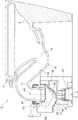
先ず、図1及び図2により、本発明の実施形態による水洗大便器を説明する。図1は、本発明の実施形態による水洗大便器を示す上面図であり、図2は、図1のII−II線に沿って見た断面図である。
Hereinafter, a flush toilet according to an embodiment of the present invention will be described with reference to the accompanying drawings.
First, referring to FIGS. 1 and 2, a flush toilet according to an embodiment of the present invention will be described. FIG. 1 is a top view showing a flush toilet according to an embodiment of the present invention, and FIG. 2 is a cross-sectional view taken along line II-II in FIG.
図1及び図2に示すように、本発明の実施形態による水洗大便器1は、所謂、壁排水タイプの水洗大便器であり、便器本体2を備え、この便器本体2には、リム吐水口(図示せず)と、汚物を受けるボウル部4と、このボウル部4の底部から延び汚物を外部へ排出するためのトラップ排水路6が形成されている。
トラップ排水路6は、ボウル部4の底部に設けられた入口部8と、この入口部8から頂部10に向かって斜め上方に延びた立上管路12と、この頂部10から鉛直方向下方に向かう立下管路14とを備えている。
As shown in FIGS. 1 and 2, a
The
トラップ排水路6の立下管路14の下端には、排水ソケット16が接続され、排水ソケット16は、流路がほぼ直角に屈曲した屈曲管路18と、その下流側が便器後方の壁に向かって横方向に延びる横排水管路20と、排水ソケット16全体の高さ等の位置を変更できる位置調節機構25と、停電時に使用するフラッパー弁26とを備えている。従って、トラップ排水路6の立下管路14の下端に、排水ソケット16の屈曲管路18が接続され、さらに、この屈曲管路18の便器後方側の下流端には、横方向に延びる横排水管路20が接続されている。この横排水管路20の下流端は、排水管(図示せず)を介して室内の排水管(図示せず)に接続される。
本実施形態の水洗大便器においては、屈曲管路18及び横排水管路20の部分を、トラップ排水路6とは別体の樹脂製の排水ソケット16としている。この排水ソケット16は、その上流端(上端)が、ゴム製のシール材22により、トラップ排水路6の立下管路14の下端に着脱自在に取り付けられるようになっている。
なお、他の実施形態(図示せず)においては、トラップ排水路の立上管路と立下管路、屈曲管路、及び、横排水管路が、陶器製であり、焼結により便器本体と共に一体的に成形されていてもよい。
A
In the flush toilet of this embodiment, the
In other embodiments (not shown), the rising and falling pipes, the bent pipes, and the horizontal drainage pipes of the trap drainage are made of earthenware, and the toilet body is made by sintering. In addition, it may be integrally formed.
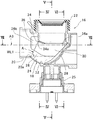
次に、図3乃至図7により、屈曲管路18について詳細に説明する。図3は、図2の排水ソケットを拡大した拡大断面図であり、図4は図3のIV−IV線に沿って見た断面図であり、図5は図3のV−V線に沿って見た断面図であり、図6は図3のVI−VI線に沿って見た断面図であり、図7は図3のVII−VII線に沿って見た断面図である。
屈曲管路18は、鉛直方向下方に向かう立下管路14の下端から横方向に延びる横排水管路20までを接続する屈曲した管路であり、その底部において下方へ向かう椀形状(平皿形状)の凹みが形成されて洗浄水が溜まる水溜り部24と、屈曲管路18の内側下面の幅方向の右側端部をR形状に形成したR形状部28と、屈曲管路18の内側右側面36にほぼ平坦な面形状に形成された平坦面30を備えている。
本発明の実施形態において、「右側」は便器本体2の前方に立って使用する場合の使用者側から見た場合における右側を示し、「左側」は便器本体2の前方に立って使用する場合の使用者側から見た場合における左側を示している。
Next, the
The
In the embodiment of the present invention, “right side” indicates the right side when viewed from the user side when standing in front of the
図1及び図4等に示すように、屈曲管路18の左右方向中央の軸線A0は、便器本体2の左右方向中央の軸線A1、及び立下管路14の左右方向中央の軸線A2、及び横排水管路20の左右方向中央の軸線A3と同一の左右方向中央の平面上に配置されている。これに対し、屈曲管路18内に形成された通水路の中心線A4は、以下に説明するように屈曲管路18内に左右非対称の通水路が形成されるので、左右非対称の通水路の形状に応じて、屈曲管路18の左右方向中央の軸線A0からずれて偏心された位置となっている。本発明の実施形態では、通水路中心線A4は、横排水管路20の軸線A3から水平方向に偏心された位置に配置されている。
As shown in FIG. 1 and FIG. 4 and the like, the axis A0 in the center in the left-right direction of the
屈曲管路18の水溜り部24は、屈曲管路18の内側下面の底部32の通水路を下方に拡げるように形成されている。水溜り部24においては、洗浄水が水位WL1まで溜まるようになっている。従って、屈曲管路18内において、立下管路14から流下してきた汚物等は屈曲管路18の流入部下端34と水溜り部24との間の領域を通過することができるようになっており、且つ立下管路14から流下してきた洗浄水は屈曲管路18の流入部下端34と水溜り部24に溜まっている洗浄水の水位WL1との間の空間領域を洗浄水で満たして水膜を形成し、屈曲管路18の通水路の断面の水膜によるシールを達成することができるようになっている。具体的に、流入下端34の下流側端34aと横排水管路20の下方側の上流側端20aとの間の通水路の断面Aで水膜によるシールを達成することができるようになっていることが好ましい。
The
屈曲管路18のR形状部28は、屈曲管路18の左右方向中央の軸線A0に対して一方側の平坦面30が形成される側の屈曲管路18の内側下面の幅方向の端部においてR形状に形成されている。R形状部28は、立下管路14から流下する洗浄水を、水溜り部24からR形状部28に沿って平坦面30に上昇させやすくすることができる。
The R-shaped
屈曲管路18の内側右側面36においては、平坦面30が、屈曲管路18の左右方向中央の軸線A0に対して一方側の通水路の内側側面を形成し、屈曲管路18内の湾曲した内周左側面38が、上記水洗大便器の左右方向中央の軸線に対して他方側の通水路の内側側面を形成している。
平坦面30は、本実施形態においては屈曲管路18の内側右側面36に形成されているが、屈曲管路18の内側左側面に形成されていてもよく、屈曲管路18内の左右方向中央の軸線A0に対して左右の通水路を左右非対称に形成するように屈曲管路18の内側側面が他の形状に形成されてもよく、屈曲管路18の内側両側面のうち少なくとも1面を平坦な形状にするように形成してもよい。
On the inner
In the present embodiment, the
平坦面30は、屈曲管路18の内側右側面36における、立下管路14の下端から横排水管路20の上流端までの領域のうち、R形状部28より上部のほぼ全体の領域にわたって形成されている。
The
平坦面30は、便器本体2の上下方向において、屈曲管路18の内側右側面36において、ほぼ垂直方向に直立する壁面として形成されている。平坦面30は、R形状部28の上端から上方に、立下管路14の下端と屈曲管路18との接続位置が変動した場合にも平坦面30が立下管路14の下端に形成されるように、屈曲管路18の上端近傍まで延びて形成されている。この平坦面30は、完全に平坦な面のみでなく、若干の湾曲や若干の凹凸の面も含むものである。
The
平坦面30は、便器本体2の左右方向において、図4乃至図6に示すように、屈曲管路18の左右方向中央の軸線A0から距離l1の位置に配置されている。この距離l1は、屈曲管路18内の平坦面30が形成されていない側における軸線A0から屈曲管路18の内周左側面38までの距離l2よりも小さく設定されている。
As shown in FIGS. 4 to 6, the
平坦面30は、便器本体2の前後方向において、屈曲管路18の内側右側面36のほぼ前端部36aからほぼ後端部36bにわたって形成されている。
ここで、平坦面30は、便器本体2の前後方向において、便器本体2の左右方向中央で便器前後方向に延びる軸線A1と平行に延びて形成されている(且つ横排水管路20の左右方向中央の便器前後方向に延びる軸線A3とも平行に延びて形成されている)立壁状の面であるが、例えば便器本体2の便器前後方向に延びる軸線A1に対して0度乃至5度の傾斜角度で便器本体2の後方に向かって外側に開くように延びて形成されていてもよく、また、例えば便器本体の便器前後方向に延びる軸線A1に対して0度乃至5度の傾斜角度で便器本体2の後方に向かって内側に閉じるように延びて形成されていてもよい。平坦面30を上記傾斜角度で形成することにより、水流をコントロールして洗浄水の旋回流を形成し易くなるだけでなく、さらに平坦面30の形成を容易にすることができる。
The
Here, the
このように形成された平坦面30により、屈曲管路18の左右方向中央の軸線A0に対して一方側の屈曲管路18の右側通水路P1の断面形状は、屈曲管路18の左右方向中央の軸線A0に対して他方側の屈曲管路18の左側通水路P2の断面形状と異なり、屈曲管路18内には軸線A0に対して左右非対称の形状の通水路が形成されている。
ここで、屈曲管路18の左右方向中央の軸線A0に対して一方側の屈曲管路18の右側通水路P1の断面積は、軸線A0に対して他方側の屈曲管路18の左側通水路P2の断面積よりも小さく形成されている。
Due to the
Here, the cross-sectional area of the right-side water passage P1 of the
本発明の実施形態の水洗大便器1は、所謂、壁排水タイプの水洗大便器であるが、変形例として、屈曲管路が、便器本体前方に向けて屈曲され、この屈曲管路の便器前方側の下流端には、床下に向かって縦方向に排水する縦排水管路が接続されているような、所謂、床排水タイプの水洗大便器にも本発明を適用することができる。
このように構成された変形例においても、屈曲管路の内側側面には、同様な、平坦面が形成されているので、上述した本発明の実施形態と同様な作用効果が奏される。
この変形例において、屈曲管路及び縦排水管路の部分を、トラップ排水路とは別体の樹脂製の排水ソケットとすることができ、また、トラップ排水路の立上管路と立下管路、屈曲管路、及び、縦排水管路が、陶器製であり、焼結により便器本体と共に一体的に成形されていてもよい。
The
Also in the modified example configured as described above, since the same flat surface is formed on the inner side surface of the bent conduit, the same effects as those of the above-described embodiment of the present invention are exhibited.
In this modification, the bent drainage pipe and the vertical drainage pipe can be made of resin drainage sockets that are separate from the trap drainage, and the trap drainage rise and fall pipes The road, the bent pipe, and the vertical drain pipe are made of earthenware, and may be integrally formed with the toilet body by sintering.
次に、本発明の実施形態による屈曲管路18内の洗浄水の流れを説明する。
図8は本発明の実施形態による屈曲管路18内の洗浄水の流れを下流方向(横排水管路20)から見て概略的に示す概略図である。ここで図8においては、洗浄水の流れを矢印で概略的に示している。
先ず、使用者により洗浄スイッチ(図示せず)が操作されると、リム吐水口(図示せず)から便器本体2内のボウル部4に洗浄水が供給される。これにより、ボウル部4の溜水の水位が上昇すると共に、トラップ排水路6内にも洗浄水が流入する。洗浄水は、トラップ排水路6の入口部8から立上管路12内を上昇し、次に、立下管路14内で鉛直方向下方に落下し、排水ソケット16の屈曲管路18に流入する。
屈曲管路18内に流入する洗浄水は、水溜り部24に流下し、予め水溜り部24に溜まっていた洗浄水とともに、屈曲管路18の内周に沿って上昇するような流れを形成する。このとき、洗浄水は、便器正面から見て屈曲管路18の左右方向中央の軸線A0から右側の右側通水路P1においては、水溜り部24から屈曲管路18の内側下面の右側端部におけるR形状部28に沿って上昇し、便器正面から見て屈曲管路18の左右方向中央の軸線A0から左側の左側通水路P2においては、水溜り部24から屈曲管路18の内周左側面38に沿って上に流れる。
Next, the flow of cleaning water in the
FIG. 8 is a schematic view schematically showing the flow of cleaning water in the
First, when a user operates a cleaning switch (not shown), cleaning water is supplied from the rim spout (not shown) to the bowl portion 4 in the
The cleaning water flowing into the
図8に示すように、便器正面から見て屈曲管路18の左右方向中央の軸線A0から右側の右側通水路P1においては、洗浄水は、水溜り部24からR形状部28を通り平坦面30に沿って上向きに流れた後、屈曲管路18内側に向かって旋回するように流れる第1の旋回流れF1を形成する。
便器正面から見て屈曲管路18の左右方向中央の軸線A0から左側の左側通水路P2においては、洗浄水は、水溜り部24から屈曲管路18の内周左側面38に沿って上昇しながら旋回するように流れる第2の旋回流れF2を形成する。
図8に示すように、一方側の第1の旋回流れF1は、平坦面30から屈曲管路18内側に向かって旋回するように折り返して流れるので、比較的小さな旋回半径r1の旋回流れを形成し、第2の旋回流れF2は、屈曲管路18の内周左側面38に沿って屈曲管路18の右側まで内周を旋回するように流れるので、第1の旋回流れF1と比較して大きな旋回半径r2の旋回流れを形成している。
従って、一方側の第1の旋回流れF1と他方側の第2の旋回流れF2とが、屈曲管路18内において、それぞれ旋回流れを形成するので二重の螺旋状の旋回流を形成するようになっている。
このように、第1の旋回流れF1と第2の旋回流れF2とが、それぞれ水流が異なる径の旋回流としてコントロールされて、第1の旋回流れF1と第2の旋回流れF2とが屈曲管路18の中心方向に向かって良好に重なり合い、屈曲管路18の通水路の中心近傍に水膜によるシールをより形成しやすくなり、洗浄が開始されてから早期に屈曲管路18の通水路の断面の水膜によるシールを形成する。この水膜によるシールが早期に形成されると、トラップ排水路6が早期に満水状態となり、サイホン作用の起動が早められる。このサイホン作用により、汚物が横排水管路20を経て外部に排出される。
As shown in FIG. 8, in the right side water passage P1 on the right side from the central axis A0 in the left-right direction of the
In the left side water passage P2 on the left side from the center line A0 in the left-right direction of the
As shown in FIG. 8, the first swirl flow F1 on one side is folded back and flows so as to swirl from the
Accordingly, the first swirl flow F1 on one side and the second swirl flow F2 on the other side form a swirl flow in the
Thus, the first swirl flow F1 and the second swirl flow F2 are controlled as swirl flows having different diameters, and the first swirl flow F1 and the second swirl flow F2 are bent pipes. It overlaps well toward the center direction of the
洗浄水及び汚物等が、立下管路14から鉛直方向下方に落下し、排水ソケット16内の屈曲管路18に流入するとき、洗浄水及び汚物等は、屈曲管路18内において平坦面30により狭められた通水路領域においても詰まることなくスムーズに搬送される。さらに、洗浄水及び汚物等は、水溜り部24が形成されているので、屈曲管路18内の通水路領域が平坦面30により狭められている状態においても、屈曲管路18の流入部下端34と水溜り部24との間の領域を詰まることなくスムーズに通過することができる。
また、屈曲管路18の通水路は通水路の中心が水平方向に偏心されているので、立下管路14から鉛直方向下方に落下した洗浄水及び汚物等は、水平方向に偏心した通水路に沿って左右非対称の旋回する流れが形成されやすく、サイホン作用の起動が早められ、更に、旋回した流れにより汚物が横排水管路20を経て外部に排出され易くなる。
このように、サイホン発生後は汚物等をスムーズに横排水管路20及び排水管(図示せず)等に搬送することができ、少ない水で汚物等を排出することが可能となる。
When washing water, filth, etc. fall vertically downward from the falling
In addition, since the center of the water flow path of the
As described above, after the siphon is generated, the filth and the like can be smoothly conveyed to the
次に、上述した本発明の実施形態による水洗大便器の作用効果を説明する。
本実施形態においては、その下流側が便器の後方に延びる横排水管路20に接続される屈曲管路18の洗浄水が通過する通水路の断面積において、屈曲管路18の左右方向中央の軸線A0に対して一方側の右側通水路P1の断面積を、他方側の左側通水路P2の断面積より小さく形成したために、立下管路14から落下してきた洗浄水が、屈曲管路18の左右方向中央の軸線A0に対して一方側の右側通水路P1内で屈曲管路18の内側右側面36に沿って上昇して内側に旋回するように流れる洗浄水の第1の旋回流れF1と、屈曲管路18の左右方向中央の軸線A0に対して他方側の左側通水路P2内で屈曲管路18の内周左側面38に沿って上昇して内側に旋回するように流れる洗浄水の第2の旋回流れF2と、を左右で異なるように形成させることができ、屈曲管路18の通水路の断面の水膜によるシールを早期に達成することができる。また、屈曲管路18の洗浄水が通過する通水路の断面積において、屈曲管路18の左右方向中央の軸線A0に対して一方側の右側通水路P1の断面積を、他方側の左側通水路P2の断面積より小さく形成するので、屈曲管路18全体の通水路の断面積を絞りすぎず、汚物等を詰まらせることを抑制しながら汚物等をスムーズに搬送することができる。このため、本発明によれば、左右一方の通水路を適度に絞って狭く形成し且つ洗浄水を左右非対称の流れにコントロールすることにより、サイホン作用を早期に発生させることができ、且つ少ない水で汚物等を排出することができ、サイホン発生後は汚物等をスムーズに搬送することが可能となる。
Next, the effect of the flush toilet according to the above-described embodiment of the present invention will be described.
In the present embodiment, in the cross-sectional area of the water passage through which the wash water of the
また、本実施形態においては、屈曲管路18は屈曲管路18の左右方向中央の軸線A0に対して一方側の内側側面が平坦面30に形成されているので、屈曲管路18の左右方向中央の軸線A0に対して一方側のこの平坦面30に沿った比較的小さな旋回半径r1の第1の旋回流れF1を形成し、他方側では平坦面30に沿った比較的小さな旋回半径r1の旋回流れよりも屈曲管路18の内側側面に沿ったより大きな旋回半径r2の第2の旋回流れF2を形成することができるので、これら一方側の第1の旋回流れF1と他方側の第2の旋回流れF2とが屈曲管路18の内側で良好に重なり合い、屈曲管路18の通水路の断面の水膜によるシールを早期に達成することができる。また、屈曲管路18は、屈曲管路18の左右方向中央の軸線A0に対して一方側の内側右側面36が平坦面30に形成されているので、屈曲管路18全体の通水路の断面積を絞りすぎず、汚物等を詰まらせることを抑制しながら汚物等をスムーズに搬送することができる。このため、本発明によれば、左右一方の通水路を適度に絞って狭く形成し且つ洗浄水を左右非対称の旋回流としてコントロールすることにより、サイホン作用を早期に発生させることができ、且つ少ない水で汚物等を排出することができ、サイホン発生後は汚物等をスムーズに搬送することが可能となる。
In the present embodiment, the
また、本実施形態においては、屈曲管路18は平坦面30から下方に延びるR形状部28が形成されているので、立下管路14から落下してきた洗浄水が、屈曲管路18のR形状部28に沿って上方にガイドされ、屈曲管路18内でR形状部28から上方に平坦面30に沿って上昇した後内側に旋回するように流れ易くなり、屈曲管路18の通水路の断面の水膜を形成して断面をシールし易くなり、サイホン作用の起動をさらに早めることができる。
In the present embodiment, the
また、本実施形態においては、屈曲管路18は、R形状部28から上方のほぼ全体において、一方側の内側右側面36が、平坦面30に形成されているので、確実に、屈曲管路18の左右方向中央の軸線に対して一方側のこの平坦面30に沿った比較的小さな旋回半径r1の第1の旋回流れF1を形成し、他方側では平坦面30に沿った比較的小さな旋回半径r1の第1の旋回流れF1よりも屈曲管路18の内周左側面38に沿ったより大きな旋回半径r2の第2の旋回流れF2を形成することができるので、これら一方側の第1の旋回流れF1と他方側の第2の旋回流れF2とが屈曲管路18の内側で確実に重なり合い、屈曲管路18の通水路の断面の水膜によるシールを早期に達成することができる。また、屈曲管路18は、R形状部28から上方のほぼ全体において、一方側の内側右側面36が平坦面30形状に形成されているので、屈曲管路18全体の通水路の断面積を絞りすぎず、汚物等を詰まらせることを抑制しながら汚物等をスムーズに搬送することができる。このため、本発明によれば、左右一方の通水路を適度に絞って狭く形成し且つ洗浄水を左右非対称の旋回流としてコントロールすることにより、サイホン作用を早期に確実に発生させることができ、且つ少ない水で汚物等を排出することができ、サイホン発生後は汚物等をスムーズに搬送することが可能となる。
Further, in the present embodiment, the
このように構成された本発明においては、屈曲管路18が、屈曲管路18の内側下面の底部に、水溜り部24を形成しているので、立下管路14から落下してきた洗浄水が予め水溜り部24に溜まっていた洗浄水と合わさって、予め水溜り部24に溜まっていた洗浄水を用いながら、屈曲管路18の通水路の断面の水膜によるシールをより早期に達成することができる。また、屈曲管路18は、屈曲管路18の内側下面の底部に、水溜り部24を形成しているので、汚物等が長大である場合にもこの水溜り部24を通過することができ、屈曲管路18全体の通水路の断面積を絞りすぎず、汚物等の詰まりを抑制しながら、汚物等をスムーズに搬送することができる。このため、本発明によれば、左右一方の通水路を適度に絞って狭く形成し且つ洗浄水を左右非対称の旋回流としてコントロールすることにより、サイホン作用を早期に発生させることができ、且つ少ない水で汚物等を排出することができ、サイホン発生後は汚物等をスムーズに搬送することが可能となる。
In the present invention configured as described above, the
このように構成された本発明においては、屈曲管路18及び横排水管路20が、立下管路14に着脱自在に取り付けられた排水ソケット16により形成されているので、便器への取り付け等が容易となり、また、設計及び製造の自由度が向上する。
In the present invention configured as described above, the
このように構成された本発明においては、水洗大便器1が、その下流側が便器の後方に延びる壁排水用の排水管路を有する場合及びその下流側が便器の床下方向に延びる床排水用の排水管路を有する場合にも、屈曲管路18の洗浄水が通過する通水路の断面積において、屈曲管路18の左右方向中央の軸線A0に対して一方側の右側通水路P1の断面積を、他方側の左側通水路P2の断面積より小さく形成したために、立下管路14から落下してきた洗浄水が、屈曲管路18の左右方向中央の軸線A0に対して一方側の右側通水路P1内で屈曲管路18の内側右側面36に沿って上昇して内側に旋回するように流れる洗浄水の第1の旋回流れF1と、屈曲管路18の左右方向中央の軸線A0に対して他方側の左側通水路P2内で屈曲管路18の内周左側面38に沿って上昇して内側に旋回するように流れる洗浄水の第2の旋回流れF2と、を左右で異なるように形成させることができ、屈曲管路18の通水路の断面の水膜によるシールを早期に達成することができる。また、屈曲管路18の洗浄水が通過する通水路の断面積において、屈曲管路18の左右方向中央の軸線A0に対して一方側の右側通水路P1の断面積を、他方側の左側通水路P2の断面積より小さく形成するので、屈曲管路18全体の通水路の断面積を絞りすぎず、汚物等を詰まらせることを抑制しながら汚物等をスムーズに搬送することができる。このため、本発明によれば、左右一方の通水路を適度に絞って狭く形成し且つ洗浄水を左右非対称の旋回流としてコントロールすることにより、サイホン作用を早期に発生させることができ、且つ少ない水で汚物等を排出することができ、サイホン発生後は汚物等をスムーズに搬送することが可能となる。
In the present invention configured as described above, when the
1 水洗大便器
2 便器本体
4 ボウル部
6 トラップ排水路
8 入口部
10 頂部
12 立上管路
14 立下管路
16 排水ソケット
18 屈曲管路
20 横排水管路
22 シール材
24 水溜り部
26 フラッパー弁
28 R形状部
30 平坦面
32 底部
34 流入部下端
36 内側右側面
36a 前端部
36b 後端部
38 内周左側面
A0 軸線
A1 軸線
A2 軸線
A3 軸線
A4 中心線
A5 軸線
l1 距離
l2 距離
P1 右側通水路
P2 左側通水路
r1 旋回半径
r2 旋回半径
WL1 水位
DESCRIPTION OF
Claims (8)
トラップ排水路の立下管路の下流端に接続された屈曲管路と、
この屈曲管路の下流端に接続された排水管路と、を有し、
上記屈曲管路は、その屈曲管路の内側に沿って流れる洗浄水の旋回流れを上記屈曲管路の左右方向中央の軸線に対して左側及び右側で異ならせるように、上記屈曲管路内の洗浄水が通過する通水路の断面積のうち、上記屈曲管路の左右方向中央の軸線に対して一方側の通水路の断面積が、他方側の通水路の断面積より小さく形成されていることを特徴とする水洗大便器。 In a flush toilet having a rising drain and a trap drain having a falling pipeline connected to the downstream end of the rising pipeline at its upstream end ,
A bent pipe connected to the downstream end of the falling pipe of the trap drain,
A drainage pipe connected to the downstream end of the bent pipe,
The bending conduit, the swirl flow of the washing water flowing along the inner side of the bent pipe to be different on the left and right relative to the axis of the horizontal center of the bending line, the bending duct Of the cross-sectional area of the water passage through which the washing water passes, the cross-sectional area of the one water passage is smaller than the cross-sectional area of the other water passage with respect to the central axis in the left-right direction of the bent pipe. A flush toilet characterized by that.
Priority Applications (1)
| Application Number | Priority Date | Filing Date | Title |
|---|---|---|---|
| JP2012217046A JP6094939B2 (en) | 2012-09-28 | 2012-09-28 | Flush toilet |
Applications Claiming Priority (1)
| Application Number | Priority Date | Filing Date | Title |
|---|---|---|---|
| JP2012217046A JP6094939B2 (en) | 2012-09-28 | 2012-09-28 | Flush toilet |
Publications (2)
| Publication Number | Publication Date |
|---|---|
| JP2014070416A JP2014070416A (en) | 2014-04-21 |
| JP6094939B2 true JP6094939B2 (en) | 2017-03-15 |
Family
ID=50745895
Family Applications (1)
| Application Number | Title | Priority Date | Filing Date |
|---|---|---|---|
| JP2012217046A Active JP6094939B2 (en) | 2012-09-28 | 2012-09-28 | Flush toilet |
Country Status (1)
| Country | Link |
|---|---|
| JP (1) | JP6094939B2 (en) |
Families Citing this family (1)
| Publication number | Priority date | Publication date | Assignee | Title |
|---|---|---|---|---|
| CN106638868A (en) * | 2015-11-02 | 2017-05-10 | 广东恒洁卫浴有限公司 | Equal-flow oblique-flushing inlet direct-falling type closestool |
Family Cites Families (3)
| Publication number | Priority date | Publication date | Assignee | Title |
|---|---|---|---|---|
| JPS5854219B2 (en) * | 1975-04-12 | 1983-12-03 | オオタケ ノボル | Rectifier bent pipe |
| WO1995027833A1 (en) * | 1994-04-08 | 1995-10-19 | Toto Ltd. | Connecting device for stool and drainage pipe |
| JP3158965B2 (en) * | 1995-06-09 | 2001-04-23 | 株式会社イナックス | Drain trap |
-
2012
- 2012-09-28 JP JP2012217046A patent/JP6094939B2/en active Active
Also Published As
| Publication number | Publication date |
|---|---|
| JP2014070416A (en) | 2014-04-21 |
Similar Documents
| Publication | Publication Date | Title |
|---|---|---|
| JP5093627B1 (en) | Flush toilet | |
| JP6472591B2 (en) | Flush toilet | |
| WO2013087195A1 (en) | Water closet | |
| JP6792187B2 (en) | Drainage socket and flush toilet equipped with it | |
| JP6848428B2 (en) | Flush toilet | |
| JP6701513B2 (en) | Flush toilet | |
| JP7055274B2 (en) | Washing toilet | |
| JP6341359B2 (en) | Flush toilet | |
| JP6094939B2 (en) | Flush toilet | |
| JP6627319B2 (en) | Flush toilet | |
| JP6826760B2 (en) | Flush toilet | |
| JP6789128B2 (en) | Flush toilet | |
| JP7118355B2 (en) | flush toilet | |
| JP2006214106A (en) | Drainage socket | |
| JP5979595B2 (en) | Flush toilet | |
| JP2022097731A (en) | Flush toilet bowl | |
| JP5674231B2 (en) | Flush toilet | |
| JP2015068127A (en) | Water closet | |
| JP2021113496A (en) | Flush toilet bowl | |
| JP6828426B2 (en) | Flush toilet | |
| JP6351064B2 (en) | Flush toilet | |
| JP6260796B2 (en) | Flush toilet | |
| EP3346065B1 (en) | Flush toilet | |
| JP6607341B2 (en) | urinal | |
| JP6843368B2 (en) | Flush toilet |
Legal Events
| Date | Code | Title | Description |
|---|---|---|---|
| A621 | Written request for application examination |
Free format text: JAPANESE INTERMEDIATE CODE: A621 Effective date: 20150909 |
|
| A977 | Report on retrieval |
Free format text: JAPANESE INTERMEDIATE CODE: A971007 Effective date: 20160608 |
|
| A131 | Notification of reasons for refusal |
Free format text: JAPANESE INTERMEDIATE CODE: A131 Effective date: 20160613 |
|
| A521 | Written amendment |
Free format text: JAPANESE INTERMEDIATE CODE: A523 Effective date: 20160810 |
|
| TRDD | Decision of grant or rejection written | ||
| A01 | Written decision to grant a patent or to grant a registration (utility model) |
Free format text: JAPANESE INTERMEDIATE CODE: A01 Effective date: 20170123 |
|
| R150 | Certificate of patent or registration of utility model |
Ref document number: 6094939 Country of ref document: JP Free format text: JAPANESE INTERMEDIATE CODE: R150 |
|
| A61 | First payment of annual fees (during grant procedure) |
Free format text: JAPANESE INTERMEDIATE CODE: A61 Effective date: 20170205 |