JP7100867B2 - Manufacturing method of ceramic molded body and ceramic molded body - Google Patents
Manufacturing method of ceramic molded body and ceramic molded body Download PDFInfo
- Publication number
- JP7100867B2 JP7100867B2 JP2020044536A JP2020044536A JP7100867B2 JP 7100867 B2 JP7100867 B2 JP 7100867B2 JP 2020044536 A JP2020044536 A JP 2020044536A JP 2020044536 A JP2020044536 A JP 2020044536A JP 7100867 B2 JP7100867 B2 JP 7100867B2
- Authority
- JP
- Japan
- Prior art keywords
- ceramic molded
- molded body
- irradiation
- ceramic
- crack length
- Prior art date
- Legal status (The legal status is an assumption and is not a legal conclusion. Google has not performed a legal analysis and makes no representation as to the accuracy of the status listed.)
- Active
Links
Images


Description
本発明は、積層造形法によりセラミックス成形体を製造するセラミックス成形体の製造方法および当該製造方法により製造したセラミックス成形体に関する。 The present invention relates to a method for manufacturing a ceramic molded body for manufacturing a ceramic molded body by a laminated molding method and a ceramic molded body manufactured by the manufacturing method.
従来、3次元積層造形技術(Additive Manufacturing、以下、AMともいう)は、3次元CADデータから立体複雑形状を付加製造により造形する技術である。AMは、形状確認などの試作を中心とした利用から、造形体を最終製品の部材として利用するダイレクトデジタルマニュファクチャリング(DMM)へと移行しつつあり、部材として利用できる素材も金属材料、スーパーエンジニアリングプラスティックなど各種材料の開発が進んでいる。一方、セラミックスに関しては、専用の造形装置は少なく、国内の3D製品化事例も極めて少ないのが現状である。セラミックスは、金属材料と比較して硬質脆性の難削材料であるため、以前から加工の必要のない最終形状やニアネットシェイプが求められており、セラミックスのAMに対する期待は大きい。 Conventionally, a three-dimensional laminated modeling technique (Adaptive Manufacturing, hereinafter also referred to as AM) is a technique for modeling a three-dimensional complex shape from three-dimensional CAD data by additional manufacturing. AM is shifting from using mainly prototypes such as shape confirmation to direct digital manufacturing (DMM) that uses the modeled body as a member of the final product, and the materials that can be used as members are also metal materials and supermarkets. Development of various materials such as engineering plastics is in progress. On the other hand, regarding ceramics, there are few dedicated modeling devices, and there are very few cases of 3D commercialization in Japan. Since ceramics are a difficult-to-cut material that is hard and brittle compared to metal materials, there has been a demand for a final shape and near-net shape that do not require processing for some time, and there are great expectations for ceramics AM.
セラミックスのAMは、光造形法、粉末床溶融結合法、材料押出法など各種提案されている。特許文献1は、粉末床溶融結合法(パウダーベッド法)によるセラミックス造形を示したものであり、セラミックス微粒子を液状の熱硬化性樹脂等の中に分散させる工程と、当該分散工程にて得られた混合物を硬化させる工程と、当該硬化工程にて得られた硬化物を、セラミックス微粒子よりも粒径が大きい粒子に粉砕して造形材料を得る工程とを備える、3次元造形に用いられる造形材料の製造方法が示されている。しかしながら、特許文献1に記載の技術は、積層造形と直接焼結とを同時に行い造形ブロック体を得るものであり、セラミックスのAMにおける直接焼結造形は、金属積層造形における粉末床溶融結合法と同じ考え方であるため、将来期待される工法であるものの、セラミックスは高温において溶融結合するとガラス化し、セラミックス本来の特性を発現できず、また、数十ミクロンの顆粒や粉末を使用するため高精細な造形が困難であった。
Various types of AM for ceramics have been proposed, such as a stereolithography method, a powder bed melt bonding method, and a material extrusion method.
また、材料押出法を利用してセラミックスの三次元形状の部材を製造する手法は、積層形成されている層間の密着強度が弱い場合や、層間(z方向)や横方向(xy方向)に欠陥が生じる恐れがある。このために、三次元積層部材の機械的強度が、要求されている強度よりも大幅に小さくなってしまうという問題や、積層形成されている層間等で破断が発生するという問題が生じる虞がある。 Further, in the method of manufacturing a three-dimensional ceramic member by using the material extrusion method, when the adhesion strength between the laminated layers is weak, or when the layers (z direction) or the lateral direction (xy direction) are defective. May occur. For this reason, there is a possibility that the mechanical strength of the three-dimensional laminated member becomes significantly smaller than the required strength, and that breakage occurs between the layers formed in the laminated layer. ..
一方、光造形法は高精細な造形が可能な工法として知られている。光造形法は、光の照射方向により、上面照射(自由液面法)と下面照射(規制液面法)に大別され、光の照射方法によって、レーザ式点露光走査タイプとプロジェクタ(DLP)式面露光タイプに分けられる。これらの中で下面照射型DLP式光造形法は、透明シート等を通して下面から光を照射するものであり、露光面がフラットであり、複雑なスキージング機構が必要ないため装置が簡便となる傾向にあり、一層ごと画像データを投影し積層させることで、迅速かつ安価に造形物を作製することができる。 On the other hand, the stereolithography method is known as a method capable of high-definition modeling. Stereolithography is roughly divided into top surface irradiation (free liquid level method) and bottom surface irradiation (regulated liquid level method) according to the light irradiation direction, and laser point exposure scanning type and projector (DLP) depending on the light irradiation method. It can be divided into formula surface exposure types. Among these, the bottom surface irradiation type DLP stereolithography method irradiates light from the bottom surface through a transparent sheet or the like, has a flat exposed surface, and does not require a complicated squeezing mechanism, so that the device tends to be simple. By projecting image data layer by layer and stacking them, it is possible to produce a modeled object quickly and inexpensively.
光造形法によるセラミックス造形として、特許文献2には、(A)電子顕微鏡法による数平均粒径が0.01~0.5μmのセラミックス粒子と、(B)重合性官能基を有する化合物と、(C)光重合開始剤を含有してなる光硬化性液状組成物とを有する光硬化性液状組成物を用いることで、セラミックス粉体等とバインダー組成物との混合物中に占めるセラミックス充填率を増加させても良好な流動性と光硬化性を示すことができ、光積層造形法により、所望の立体形状物を容易に造形できる立体形状物の製造方法が開示されている。しかしながら、特許文献2は、基本的に、レーザ式点露光走査タイプによるセラミックス造形に関するものであり、照射条件が造形精度に及ぼす影響の詳細については示されておらず、また造形焼結体の欠陥や強度特性についても示されていない。 As ceramics molding by stereolithography, Patent Document 2 describes (A) ceramic particles having a number average particle size of 0.01 to 0.5 μm by electron microscopy, and (B) a compound having a polymerizable functional group. (C) By using a photocurable liquid composition having a photocurable liquid composition containing a photopolymerization initiator, the ceramic filling ratio in the mixture of the ceramic powder or the like and the binder composition can be determined. A method for producing a three-dimensional shape object, which can exhibit good fluidity and photocurability even when the amount is increased and can easily form a desired three-dimensional shape object by a photolamination modeling method, is disclosed. However, Patent Document 2 basically relates to ceramics molding by a laser point exposure scanning type, does not show details of the influence of irradiation conditions on molding accuracy, and is a defect of the molded sintered body. And strength characteristics are not shown.
また、特許文献3には、セラミックス粒子に重合性不飽和基を結合することで、粒子に紫外線重合性を付与し、この粒子を含む紫外線硬化性樹脂組成物の層中に光学的手法を用いて紫外線を集光せしめ、その集光位置を三次元的に移動させて任意の位置を硬化することで、微細な三次元形状を得る技術が開示されている。また、特許文献3には、粒径が70nm以下と極めて微細なセラミックス粒子を用いれば、紫外線の透過率が高く、かつ光の散乱も抑制できるため、より微細かつ複雑な造形が可能となることも示されている。このように、特許文献3では、紫外線の透過率が高く、かつ光の散乱が抑制できる極めて微細なセラミックス粒子を用いることで、微細かつ複雑な造形が可能となることを示すものであるが、緻密な焼結体を得るには、造形後、流動性セラミックス材料の含侵工程が必要であり、この工程においては、造形体の表面に流動性セラミックス材料が堆積し内部にまで十分均一に浸透しない恐れがあるとともに、この工法においては、基本的に、1~1000μmオーダーの微小造形体を作製するものであり、数ミリメートル~数センチメートル以上の造形体の作製には適していなかった。 Further, in Patent Document 3, an ultraviolet polymerizable property is imparted to the particles by bonding a polymerizable unsaturated group to the ceramic particles, and an optical method is used in the layer of the ultraviolet curable resin composition containing the particles. Disclosed is a technique for obtaining a fine three-dimensional shape by condensing ultraviolet rays and moving the condensing position three-dimensionally to cure an arbitrary position. Further, in Patent Document 3, if extremely fine ceramic particles having a particle size of 70 nm or less are used, the transmittance of ultraviolet rays is high and the scattering of light can be suppressed, so that finer and more complicated modeling becomes possible. Is also shown. As described above, Patent Document 3 shows that fine and complicated modeling is possible by using extremely fine ceramic particles having high transmittance of ultraviolet rays and capable of suppressing light scattering. In order to obtain a dense sintered body, an impregnation step of the fluid ceramic material is required after molding. In this step, the fluid ceramic material is deposited on the surface of the molded body and penetrates sufficiently evenly into the inside. In addition, there is a risk that this method will not be used, and in this method, a micro model of 1 to 1000 μm order is basically produced, and it is not suitable for producing a model of several millimeters to several centimeters or more.
光造形法の一種である下面照射型DLP式光造形法は、高精細なセラミックス造形体を作製することが可能であるが、当該工法を活用したセラミックス造形においては、造形方法に由来する種々造形欠陥が内在し、そのため、射出成形等の従来工法と比較して機械的特性が低下する可能性がある。想定される具体的な造形欠陥は、次の3つである。
(1)接着阻害する因子が界面に存在することで、積層界面の不十分な接合による界面剥離(デラミネーション)
(2)各積層ピッチ内における照射エネルギー差に起因した端面段差
(3)プロジェクタの分解能(ピクセル)由来の端面段差
The bottom-illuminated DLP-type stereolithography, which is a type of stereolithography, can produce high-definition ceramic moldings, but in ceramics molding utilizing this method, various moldings derived from the molding method are used. Defects are inherent and may therefore reduce mechanical properties as compared to conventional methods such as injection molding. There are the following three specific modeling defects that can be assumed.
(1) Delamination due to insufficient bonding of laminated interfaces due to the presence of factors that inhibit adhesion at the interface.
(2) End face step due to irradiation energy difference in each stacking pitch (3) End face step due to projector resolution (pixels)
下面照射型DLP式光造形法において、これらすべての課題を効率的かつ最適に改善した方法は報告されていない。これら課題を克服しなければ、十分な機械的特性を有するセラミックス造形体は得られず、セラミックスの高品位なDDMを達成することはできない。 No method has been reported for efficiently and optimally improving all of these problems in the bottom-illuminated DLP stereolithography method. Unless these problems are overcome, a ceramic model having sufficient mechanical properties cannot be obtained, and high-quality DDM of ceramics cannot be achieved.
本発明は、下面照射型DLP式光造形法において、上記造形欠陥を改善し、立体複雑形状を有する高精細なセラミックス成形体の製造方法、およびそれにより作製したセラミックス成形体を提供することを目的としている。 It is an object of the present invention to provide a method for producing a high-definition ceramic molded product having a three-dimensional complex shape by improving the above-mentioned modeling defects in a bottom-illuminated DLP-type stereolithography method, and providing a ceramic molded product produced by the method. It is supposed to be.
本発明は上記課題を解決するためになされた。すなわち、本発明の主な目的は、三次元積層造形法により製造されるセラミックス成形体の機械的強度を高めることができる技術を提供することにある。 The present invention has been made to solve the above problems. That is, a main object of the present invention is to provide a technique capable of increasing the mechanical strength of a ceramic molded product manufactured by a three-dimensional laminated molding method.
本発明は下記(1)ないし(7)のセラミックス成形体の製造方法を要旨とする。
(1) 下面照射型DLP式光造形法によるセラミックス成形体の製造方法において、
焼結後の前記セラミックス成形体の端面段差が臨界亀裂長さよりも小さくなる積層ピッチを設定し、前記積層ピッチで各層を積層する造形工程と、造形したセラミック成形体を、常圧で焼成する焼成工程と、を有し、前記臨界亀裂長さは、下記式に基づいて求められる、セラミックス成形体の製造方法。
![]()
セラミックス成形体の製造方法。
(2)前記造形工程において、各層を鉛直方向に対して斜め方向に積層させる場合に、前記端面段差が臨界亀裂長さよりも小さくなる照射単位面積で照射光の照射範囲を制御しながら、各層を積層造形することを特徴とする、上記(1)に記載のセラミックス成形体の製造方法。
(3)前記造形工程において、積層ピッチに対して1/5以下の平均粒子径を有するセラミックス粉末を、光硬化性樹脂に10体積%以上80体積%以下添加した光硬化性セラミックススラリーを使用して造形することを特徴とする、上記(1)または(2)に記載のセラミックス成形体の製造方法。
(4)前記造形工程において使用する光硬化性セラミックススラリーの粘度が300mPa・s~5000mPa・sであることを特徴とする、上記(1)ないし(3)のいずれかに記載のセラミックス成形体の製造方法。
(5)前記造形工程において、積層ピッチに応じて特定される必要最小照射エネルギーの1.2~3.0倍の照射エネルギーの照射光を照射して造形を行うことを特徴とする、上記(1)ないし(4)のいずれかに記載のセラミックス成形体。
(6)前記造形工程において、照射光の照射エネルギーを一定としながら照射強度を低くすることで硬化深さが低下し始める照射強度を基準照射強度とした場合に、照射光の照射強度を前記基準照射強度の40~200%の強度にして造形を行うことを特徴とする、上記(1)ないし(5)のいずれかに記載のセラミックス成形体。
(7)焼結後のセラミックス成形体において、積層界面剥離が生じておらず、かつ、寸法誤差が5%以内である、上記(1)ないし(6)のいずれかに記載のセラミックス成形体の製造方法。
The gist of the present invention is the method for producing a ceramic molded product according to the following (1) to (7).
(1) In the method for manufacturing a ceramic molded body by a bottom-illuminated DLP-type stereolithography method .
A molding process in which the end face step of the ceramic molded body after sintering is set to be smaller than the critical crack length and each layer is laminated at the laminated pitch , and the molded ceramic molded body is fired at normal pressure. A method for manufacturing a ceramic molded body, which comprises a step and the critical crack length is determined based on the following formula .
![]()
A method for manufacturing a ceramic molded product.
(2) In the modeling step, when each layer is laminated in an oblique direction with respect to the vertical direction, each layer is controlled while controlling the irradiation range with an irradiation unit area in which the end face step is smaller than the critical crack length. The method for manufacturing a ceramic molded body according to (1) above, which comprises laminating molding.
(3) In the molding step, a photocurable ceramic slurry obtained by adding 10% by volume or more and 80% by volume or less of ceramic powder having an average particle diameter of 1/5 or less with respect to the stacking pitch to a photocurable resin is used. The method for producing a ceramic molded product according to (1) or (2) above, which is characterized by molding.
(4) The ceramic molded product according to any one of (1) to (3) above, wherein the photocurable ceramic slurry used in the molding step has a viscosity of 300 mPa · s to 5000 mPa · s. Production method.
(5) The above-mentioned (5), which is characterized in that, in the modeling step, irradiation light with an irradiation energy of 1.2 to 3.0 times the required minimum irradiation energy specified according to the stacking pitch is irradiated to perform modeling. The ceramic molded body according to any one of 1) to (4).
(6) In the modeling step, when the irradiation intensity at which the curing depth begins to decrease by lowering the irradiation intensity while keeping the irradiation energy of the irradiation light constant is set as the reference irradiation intensity, the irradiation intensity of the irradiation light is used as the reference. The ceramic molded body according to any one of (1) to (5) above, wherein the molding is performed with an intensity of 40 to 200% of the irradiation intensity.
(7) The ceramic molded product according to any one of (1) to (6) above, wherein the laminated interface peeling does not occur and the dimensional error is within 5% in the ceramic molded body after sintering. Production method.
また、本発明は下記(8)ないし(10)のセラミックス成形体を要旨とする。
(8) 下面照射型DLP式光造形法により成形されたセラミックス成形体であって、焼成後の前記セラミックス成形体の端面段差が臨界亀裂長さよりも小さくなる積層ピッチで、各層が積層されており、前記臨界亀裂長さは、下記式に基づいて求めることができる、セラミックス成形体。
![]()
(9)焼成後の前記端面段差が臨界亀裂長さよりも小さいことを特徴とする、上記(8)に記載のセラミックス成形体。
(10)焼結後に積層界面剥離が生じておらず、かつ、寸法誤差が5%以内である、上記(8)または(9)に記載のセラミックス成形体。
Further, the gist of the present invention is the ceramic molded body of the following (8) to (10).
(8) A ceramic molded body molded by a bottom-illuminated DLP-type stereolithography method , in which each layer is laminated at a stacking pitch in which the step on the end face of the ceramic molded body after firing is smaller than the critical crack length . , The critical crack length can be obtained based on the following formula, a ceramic molded product.
![]()
(9) The ceramic molded product according to (8) above, wherein the step on the end face after firing is smaller than the critical crack length.
(10) The ceramic molded product according to (8) or (9) above, wherein the laminated interface is not peeled off after sintering and the dimensional error is within 5%.
造形体の界面剥離や端面段差が少なくなり、従来工法と比較して遜色のない機械的特性を有するとともに、AMならではの立体複雑形状を具備する高付加価値な高精細セラミックス成形体を創製することが可能となる。 To create a high-value-added high-definition ceramic molded body that has mechanical properties comparable to those of conventional construction methods, with less interfacial peeling and end face steps of the modeled body, and has a three-dimensional complex shape unique to AM. Is possible.
《3次元積層造形機》
以下、図に基づいて、本発明に係るセラミックス成形体の実施形態を説明する。図1は、本実施形態に係るセラミックス成形体を成形するための3次元積層造形機1の構成図である。また、図2は、3次元積層造形技術の概略を説明するための図である。
<< 3D laminated modeling machine >>
Hereinafter, embodiments of the ceramic molded product according to the present invention will be described with reference to the drawings. FIG. 1 is a configuration diagram of a three-dimensional
図1に示すように、3次元積層造形機1は、制御装置10と、紫外線光などの照射光を照射するプロジェクタ20とを有し、プロジェクタ20により照射された照射光の照射先に、光硬化性セラミックススラリー(光硬化性樹脂液体とセラミックス粉末との混合物)を充填するための透明樹脂トレイ30が配置される。
As shown in FIG. 1, the three-dimensional
本実施形態では、セラミックス成形体の完成形のCADデータが制御装置10に入力され、制御装置10により、セラミックス成形体のスライスデータが作成される。そして、制御装置10は、図2に示すように、作成したスライスデータに基づいて、プロジェクタ20に照射光を照射させ、光硬化性セラミックススラリーを層ごとに硬化させることで、セラミックス成形体を成形する付加製造を行う。
In the present embodiment, CAD data of the completed form of the ceramic molded body is input to the
《プロジェクタ》
プロジェクタ20は、光硬化性セラミックススラリーを硬化させるために、紫外線などの照射光を、光硬化性セラミックススラリーが充填された透明樹脂トレイ30に向けて照射する。ここで、プロジェクタ20の照射光の照射エネルギーが十分でない場合には、セラミックス造形体の積層界面において界面剥離が発生するという問題があった。一方で、プロジェクタ20の照射光の照射エネルギーを過度に大きくしてしまうと、光硬化性セラミックススラリーに屈折率の異なるセラミックス粒子が多く含まれるため、光の散乱が大きくなり、硬化させた部分に歪みが生じる場合や膨れが生じる場合があり、想定した寸法と誤差が生じてしまい、高精細な造形が行えないという問題もあった。
"projector"
In order to cure the photocurable ceramic slurry, the
《照射光》
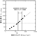
このような問題を考慮して、本実施形態に係るプロジェクタ20は、セラミックスの積層ピッチに応じた必要最小照射エネルギー(E1)の1.2~3.0倍、好ましくは1.5~2.5倍の範囲となるように、照射する照射光の照射エネルギーが設定される。ここで、積層ピッチに応じた必要最小照射エネルギーは、たとえば、光源波長405nmの光照射による単層硬化試験を行い、照射エネルギーと硬化深さの関係を次式のBeer-Lambert則を用いて求めることができる。

In consideration of such a problem, the
また、本実施形態では、照射光の照射強度も調整される。光硬化性セラミックススラリーは、光硬化性樹脂に屈折率の異なるセラミックス粒子を混合したものであり、照射強度により光の散乱の度合いが変化し、特に、セラミックス成形体の寸法制御に大きく影響すると考えられる。具体的には、照射強度を小さくすることで、光の散乱を抑制することができ、寸法制御に優れる造形が可能となる。一方で、照射強度を過度に小さくしてしまうと、照射エネルギーを、積層ピッチに応じた必要最小照射エネルギーに設定しても所望の硬化深さが得られない場合がある。そのため、本実施形態に係るプロジェクタ20では、照射光の照射強度が、所望の造形深さが造形できる基準照射強度の40~200%、好ましくは60~150%に設定される。40%より照射強度が低いと界面剥離が起こるとともに造形時間が膨大となってしまう。一方、200%より照射強度が高いと光の散乱が強くなり寸法制御が困難になる。なお、基準照射強度とは、照射エネルギーを一定とし、ある一定の硬化深さが得られる照射強度において、照射強度を小さくしていった場合に、その硬化深さが低下しはじめるときの照射強度をいう。
Further, in the present embodiment, the irradiation intensity of the irradiation light is also adjusted. The photocurable ceramics slurry is a mixture of photocurable resin and ceramic particles having different refractive indexes, and the degree of light scattering changes depending on the irradiation intensity, which is considered to have a great influence on the dimensional control of the ceramic molded body. Be done. Specifically, by reducing the irradiation intensity, light scattering can be suppressed, and modeling with excellent dimensional control becomes possible. On the other hand, if the irradiation intensity is excessively reduced, the desired curing depth may not be obtained even if the irradiation energy is set to the required minimum irradiation energy according to the stacking pitch. Therefore, in the
《光硬化性セラミックススラリー》
本実施形態では、光硬化性樹脂とセラミックス粉末とを混合した光硬化性セラミックススラリーを、プロジェクタ20により照射した照射光により硬化させることで、セラミックス成形体が成形される。なお、光硬化性セラミックススラリーは、以下のように調整することができる。まず、使用するセラミックス粉末の粒子径は、設定する積層ピッチに対して十分に小さいことが必要である。積層ピッチより大きかったり、積層ピッチに近いサイズであると十分な硬化接合が困難になり、積層が不十分となったり、積層欠陥が生じてしまう。したがって、積層ピッチに対して、1/5以下、望ましくは1/10以下の平均粒子径を有するセラミックス粉末を使用することが好ましい。また、光硬化性樹脂に添加するセラミックス粉末の含有量は、10体積%未満であると、焼成後収縮率が大きくなり亀裂の原因となるばかりか、緻密体を得るのが困難である。一方、80体積%より高いと、流動性を有するセラミックススラリーを調製することが困難である。したがって、光硬化性セラミックススラリーに含まれるセラミックス粉末は、10体積%以上かつ80体積%以下、望ましくは20体積%以上かつ60体積%以下が好ましい。また、光硬化性セラミックススラリーの粘度は、過度に高くしてしまうと、積層造形体を積層毎に吊り上げる際、界面に引張応力が働き、界面剥離を引き起こす原因となってしまう。一方、光硬化性セラミックススラリーの粘度を過度に低くしてしまうと、セラミックス粒子の分離が生じてしまう。そのため、本実施形態では、光硬化性セラミックススラリーは、粘性係数が300~5000mPa・s、好ましくは500~3000mPa・sに調整される。
《Photo-curable ceramic slurry》
In the present embodiment, the ceramic molded body is formed by curing the photocurable ceramics slurry, which is a mixture of the photocurable resin and the ceramic powder, with the irradiation light irradiated by the
《積層ピッチ》
次に、本実施形態に係るセラミックス成形体の積層ピッチについて説明する。ここで、図4(A)は、積層ピッチを150μmで造形したセラミックス成形体の端面段差を示す電子顕微鏡の写真あり、図4(B)は、積層ピッチを25μmで造形したセラミックス成形体の端面段差を示す電子顕微鏡の写真である。図4(A),(B)に示すように、積層造形法においては、各層を積層するように造形する際に、セラミックス成形体の端面(側面、積層方向の面)に端面段差が形成されてしまう。端面段差が大きい場合、積層界面において積層界面に平行方向の強度を著しく低下させるおそれがある。図4(A)および図4(B)に示すように、端面段差の大きさは、積層ピッチの大きさに依存し、たとえば図4(A)に示すように、積層ピッチを150μmで造形した場合には、端面段差は約70μmとなり、図4(B)に示すように、積層ピッチを25μmで造形した場合、端面段差は約10μmとなる。上述したように端面段差が大きいと、積層界面と平行方向の強度が著しく低下するため、積層ピッチを小さくすることで端面段差を小さくし、セラミックスの強度を高めることができる。しかしながら、積層ピッチを過度に小さくしてしまうと、セラミックスの造形にかかる時間が膨大となり、光硬化性セラミックススラリーの安定性が損なわれてしまう。そこで、本実施形態では、破壊力学に基づき、造形しようとするセラミックスが本来有する破壊源の臨界亀裂長さよりも端面段差が小さくになるように積層ピッチが設定される。
《Stacking pitch》
Next, the stacking pitch of the ceramic molded product according to the present embodiment will be described. Here, FIG. 4 (A) is a photograph of an electron microscope showing an end face step of a ceramic molded body formed with a lamination pitch of 150 μm, and FIG. 4 (B) is an end face of a ceramic molded body formed with a lamination pitch of 25 μm. It is a photograph of an electron microscope showing a step. As shown in FIGS. 4A and 4B, in the additive manufacturing method, when each layer is formed so as to be laminated, an end face step is formed on the end face (side surface, surface in the stacking direction) of the ceramic molded body. Will end up. If the end face step is large, the strength in the direction parallel to the laminated interface may be significantly reduced at the laminated interface. As shown in FIGS. 4 (A) and 4 (B), the size of the end face step depends on the size of the stacking pitch. For example, as shown in FIG. 4 (A), the stacking pitch is formed at 150 μm. In this case, the end face step is about 70 μm, and as shown in FIG. 4B, when the stacking pitch is 25 μm, the end face step is about 10 μm. As described above, when the end face step is large, the strength in the direction parallel to the laminated interface is remarkably lowered. Therefore, by reducing the stacking pitch, the end face step can be reduced and the strength of the ceramics can be increased. However, if the stacking pitch is made excessively small, the time required for forming the ceramics becomes enormous, and the stability of the photocurable ceramic slurry is impaired. Therefore, in the present embodiment, based on the fracture mechanics, the stacking pitch is set so that the step on the end face is smaller than the critical crack length of the fracture source originally possessed by the ceramic to be molded.
ここで、セラミックスの臨界亀裂長さcは、下記式2により表すことができる。
![]()
![]()
《プロジェクタの分解能》
セラミックス成形体を積層造形する場合に、各層を鉛直方向に対して斜め方向に積層する場合、図5に示すように、積層ピッチ由来の端面段差とは異なる端面段差が生じる。この段差は、積層ピッチに加えて、プロジェクタ20の照射面の分解能(1ピクセルのサイズ)に起因するものと考えられる。すなわち、DLP式光造形は面露光であり、プロジェクタ20が照射光を照射する最小の単位照射面を、プロジェクタ20の分解能として考えることができる。たとえば図5に示す例では、層Bを形成するために、プロジェクタ20の照射面のうち照射面aおよび照射面bで照射が行われるが、層Aを形成する場合には、照射面bでの照射は行われず、照射面aでの照射が行われる。このように積層方向に対して傾斜をつけてセラミックス成形体を造形する場合に、図5に示すように、端面段差が生じてしまう。ここで、端面段差の大きさは、積層ピッチと照射面の分解能(照射面の最小単位面積)に依存する。すなわち、端面段差の大きさを小さくするためには、積層ピッチを小さくするとともに、プロジェクタ20の照射面の分解能を小さくすればよい。しかしながら、積層ピッチを過度に小さくした場合の弊害は上述したとおりであるし、また、プロジェクタ20の照射面の分解能を高めるほど、装置が高額になり汎用性がなくなってしまう。そこで、鉛直方向に対して斜め方向にセラミックス成形体を造形する場合には、傾斜方向における端面段差が臨界亀裂長さよりも小さくなる照射面の分解能が得られる装置を用いて、セラミックス成形体を造形することで、斜め方向に積層したセラミックス成形体の強度低下を有効に防止することができる。
《Projector resolution》
When each layer is laminated in an oblique direction with respect to the vertical direction in the case of laminating a ceramic molded body, as shown in FIG. 5, an end face step different from the end face step derived from the stacking pitch is generated. It is considered that this step is caused by the resolution (size of 1 pixel) of the irradiation surface of the
(実施例1~11)
次に、本発明の実施例を下記表1に示す。下記表1に示すように、セラミックス粉末として、実施例1~4ではアルミナ粉末(純度99.99%、平均粒子径0.61μm)を用い、実施例5~8ではムライト粉末(平均粒子径1.2μm)を用い、実施例9~11では3molY-ジルコニア粉末(平均粒子径0.64μm)を用いた。また、実施例1~11では、光硬化性樹脂として、ラジカル重合系アクリルベースモノマー、単官能希釈モノマー、重合開始剤などを適量加えたものを用いた。この光硬化性樹脂は、屈折率が1.49であり、ずり速度3.06s-1および温度25℃において粘度計(東機産業製、R115型)で測定した粘度が48mPa・sであった。また、光硬化性樹脂の光硬化特性は、臨界照射エネルギー(Ec)が4.3mJ/cm2であり、光硬化感度(Dp)が183μmであった。
(Examples 1 to 11)
Next, examples of the present invention are shown in Table 1 below. As shown in Table 1 below, alumina powder (purity 99.99%, average particle size 0.61 μm) was used as the ceramic powder in Examples 1 to 4, and Murite powder (average particle size 1) was used in Examples 5 to 8. .2 μm) was used, and in Examples 9 to 11, 3 molY-zirconia powder (average particle size 0.64 μm) was used. Further, in Examples 1 to 11, as the photocurable resin, a radical polymerization type acrylic base monomer, a monofunctional diluted monomer, a polymerization initiator and the like were added in appropriate amounts. This photocurable resin had a refractive index of 1.49, a viscosity measured by a viscometer (manufactured by Toki Sangyo Co., Ltd., R115 type) at a shear rate of 3.06 s -1 and a temperature of 25 ° C., and was 48 mPa · s. .. The photocuring characteristics of the photocurable resin were that the critical irradiation energy (Ec) was 4.3 mJ / cm 2 and the photocuring sensitivity (Dp) was 183 μm.
本実施例では、各実施例1~11のセラミックス粉末と光硬化性樹脂とを混合し、さらに分散剤であるカルボキシル基含有の変性ポリマーを、セラミックス粉末に対して0.3~2.0wt%となる量を添加し溶解させた。また、実施例1~3,5~11では、セラミックス粉末の固形分濃度が35vol%となるように、実施例4ではセラミックス粉末の固形分濃度が40vol%となるように、セラミックス粉末と光硬化性樹脂とを混合した。そして、遊星撹拌装置(クラボウ製、マゼルスターKK-250S)を用いて混合攪拌し、光硬化性セラミックススラリーを調製した。 In this example, the ceramic powders of Examples 1 to 11 and the photocurable resin are mixed, and the modified polymer containing a carboxyl group as a dispersant is added in an amount of 0.3 to 2.0 wt% with respect to the ceramic powder. The above amount was added and dissolved. Further, in Examples 1 to 3, 5 to 11, the solid content concentration of the ceramic powder is 35 vol%, and in Example 4, the solid content concentration of the ceramic powder is 40 vol%. It was mixed with a sex resin. Then, a photocurable ceramic slurry was prepared by mixing and stirring using a planetary stirrer (Mazellster KK-250S manufactured by Kurabo Industries).
調製した光硬化性セラミックススラリーの粘度は、実施例1~3(アルミナ粉末35vol%)では728mPa・s、実施例4(アルミナ粉末40vol%)では3392mPa・s、実施例5~8(ムライト粉末35vol%)は568mPa・s、実施例9~11(ジルコニア粉末35vol%)では1216mPa・s(いずれもずり速度3.06s-1、温度25℃)であった。

セラミックス成形体の造形は、光源の波長を405nmとした下面照射型DLP式光造形装置(武藤工業製、ML-48)を用いて行った。セラミックス成形体の形状は、約2.5×2.5×10mmの直方体とし、長手方向がz軸方向と平行になるように造形した。 The ceramic molded body was molded using a bottom-illuminated DLP-type stereolithography apparatus (ML-48, manufactured by Muto Kogyo Co., Ltd.) in which the wavelength of the light source was 405 nm. The shape of the ceramic molded body was a rectangular cuboid of about 2.5 × 2.5 × 10 mm, and the shape was formed so that the longitudinal direction was parallel to the z-axis direction.
また、セラミックス成形体の造形において、上記表1に示すように積層ピッチを、実施例9では20μm、実施例1~5,10,11では25μm、実施例6~8では50μmとした。また、上記表1に示すように、実施例1~11では、プロジェクタ20の照射強度を0.27~0.84W/cm2で照射し、基準照射強度に対する相対照射強度を45~162%とした。また、実施例1~11では、照射時間を変えることで、照射エネルギー(照射強度×照射時間)を5.08~22.38mJ/cm2に調整し、必要最小照射エネルギーに対する相対照射エネルギーを150~300%とした。
Further, in the molding of the ceramic molded body, as shown in Table 1 above, the stacking pitch was set to 20 μm in Example 9, 25 μm in Examples 1 to 5, 10 and 11, and 50 μm in Examples 6 to 8. Further, as shown in Table 1 above, in Examples 1 to 11, the irradiation intensity of the
造形したセラミックス成形体は、窒素雰囲気650℃において脱脂し、大気雰囲気にて昇温速度1℃/分で1時間焼成した。なお、焼成温度は、実施例1~4(アルミナ粉末を含有)は1700℃、実施例5~8(ムライト粉末を含有)は1650℃、実施例9~11(ジルコニアを含有)は1500℃とした。焼成後のセラミックス成形体の端面段差は、FE-SEM(日本電子製JSM-7001F)を用いて評価した。 The molded ceramic molded body was degreased in a nitrogen atmosphere at 650 ° C. and fired in an atmospheric atmosphere at a heating rate of 1 ° C./min for 1 hour. The firing temperatures were 1700 ° C. for Examples 1 to 4 (containing alumina powder), 1650 ° C. for Examples 5 to 8 (containing mullite powder), and 1500 ° C. for Examples 9 to 11 (containing zirconia). did. The step on the end face of the ceramic molded product after firing was evaluated using FE-SEM (JSM-7001F manufactured by JEOL Ltd.).
上記表1に示すように、実施例1~11では、セラミックス成形体において積層界面の剥離は認められなかった。また、実施例1~11では、焼成後の寸法誤差も5%以内となった。さらに、実施例1~11では、焼成後の端面段差が臨界亀裂長さよりも小さくなっており、積層界面に対して平行方向の強度低下を有効に防止できた。このように、実施例1~11では、プロジェクタ20の照射強度を基準照射強度の40~200%の範囲とし、プロジェクタ20の照射エネルギーを各積層ピッチに対する必要最小照射エネルギーの120~300%とし、さらに、焼成後の端面段差が臨界亀裂長さよりも小さくなる積層ピッチで各層を積層造形することで、焼成後においても、積層界面の剥離がなく、寸法誤差も5%以内であり、かつ、端面段差が臨界亀裂長さよりも小さく強度の高い、セラミックス成形体を造形することができた。
As shown in Table 1 above, in Examples 1 to 11, no peeling of the laminated interface was observed in the ceramic molded product. Further, in Examples 1 to 11, the dimensional error after firing was also within 5%. Further, in Examples 1 to 11, the step on the end face after firing was smaller than the critical crack length, and it was possible to effectively prevent the strength decrease in the direction parallel to the laminated interface. As described above, in Examples 1 to 11, the irradiation intensity of the
(比較例1~11)
次に、比較例1~11について説明する。下記表2に示すように、セラミックス粉末として、比較例1~6ではアルミナ粉末(純度99.99%、平均粒子径0.61μm)を用い、比較例7~9ではムライト粉末(平均粒子径1.2μm)を用い、比較例10,11では3molY-ジルコニア粉末(平均粒子径0.64μm)を用いた。また、比較例1~11において、光硬化性樹脂は、実施例1~11と同じものを用いた。

Next, Comparative Examples 1 to 11 will be described. As shown in Table 2 below, alumina powder (purity 99.99%, average particle size 0.61 μm) was used as the ceramic powder in Comparative Examples 1 to 6, and Murite powder (average particle size 1) was used in Comparative Examples 7 to 9. .2 μm) was used, and in Comparative Examples 10 and 11, 3 molY-zirconia powder (average particle size 0.64 μm) was used. Further, in Comparative Examples 1 to 11, the same photocurable resins as those in Examples 1 to 11 were used.
また、比較例1~6は、実施例1~4と同じくアルミナ粉末を含有する光硬化性セラミックススラリーを用いてセラミックス成形体を造形するが、実施例1~4とは異なり、比較例3では積層ピッチを50μmとし、比較例4~6では積層ピッチを100μmとしてセラミックス成形体を造形した。同様に、比較例7~9は、実施例5~8と同じくムライト粉末を含有する光硬化性セラミックススラリーを用いてセラミックス成形体を造形しているが、実施例5~8とは異なり、比較例9では積層ピッチを100μmとしてセラミックス成形体を造形した。さらに、比較例10,11は、実施例9~11と同じくジルコニア粉末を含有する光硬化性セラミックススラリーを用いてセラミックス成形体を造形したが、実施例9~11とは異なり、比較例11では積層ピッチを50μmとしてセラミックス成形体を造形した。 Further, in Comparative Examples 1 to 6, the ceramic molded product is formed by using the photocurable ceramic slurry containing alumina powder as in Examples 1 to 4, but unlike Examples 1 to 4, in Comparative Example 3. In Comparative Examples 4 to 6, the stacking pitch was set to 50 μm, and the stacking pitch was set to 100 μm to form a ceramic molded body. Similarly, in Comparative Examples 7 to 9, the ceramic molded product was formed by using the photocurable ceramic slurry containing the mullite powder as in Examples 5 to 8, but unlike Examples 5 to 8, the comparison was made. In Example 9, a ceramic molded body was formed with a lamination pitch of 100 μm. Further, in Comparative Examples 10 and 11, the ceramic molded product was formed by using the photocurable ceramic slurry containing the zirconia powder as in Examples 9 to 11, but unlike Examples 9 to 11, in Comparative Example 11. A ceramic molded body was formed with a stacking pitch of 50 μm.
また、比較例1~3,7,10では、基準照射強度に対する相対照射強度を278%,30%,321%,213%,215%とし、実施例1~11における相対強度40~200%の範囲外でセラミックス成形体を造形した。さらに、比較例1、6、8、9では、必要最小照射エネルギーに対する相対照射エネルギーを301%,100%,100%,481%とし、実施例1~11における相対照射エネルギーの120~300%の範囲外でセラミックス成形体の造形を行った。 Further, in Comparative Examples 1 to 3, 7 and 10, the relative irradiation intensities with respect to the reference irradiation intensity were set to 278%, 30%, 321%, 213% and 215%, and the relative intensities of Examples 1 to 11 were 40 to 200%. A ceramic molded body was formed outside the range. Further, in Comparative Examples 1, 6, 8 and 9, the relative irradiation energy with respect to the required minimum irradiation energy was set to 301%, 100%, 100% and 481%, which was 120 to 300% of the relative irradiation energy in Examples 1 to 11. The ceramic molded body was molded outside the range.
その結果、上記表2に示すように、比較例1、3、6、7、9、10では、セラミックス成形体の寸法誤差が5%以上となった。また、比較例2、6、8では、セラミックス成形体において積層界面の剥離が観察された。さらに、比較例4、5、11では、プロジェクタ20の照射条件は適切であるが、積層ピッチが実施例1~11よりも大きく設定されており、焼結後のセラミックス成形体の端面段差が臨界亀裂長さより大きくなった。このように、比較例1~11では、プロジェクタ20の照射強度が基準照射強度の40~200%の範囲外、照射エネルギーが各積層ピッチに対する必要最小照射エネルギーの120~300%の範囲外、または、焼成後の端面段差が臨界亀裂長さよりも小さくなる積層ピッチよりも大きく設定したことで、界面剥離が観察されたり、寸法誤差が5%を超えたり、端面段差が臨界亀裂長さよりも大きくなり強度が大きく低下する恐れがあることがわかった。
As a result, as shown in Table 2 above, in Comparative Examples 1, 3, 6, 7, 9, and 10, the dimensional error of the ceramic molded product was 5% or more. Further, in Comparative Examples 2, 6 and 8, peeling of the laminated interface was observed in the ceramic molded product. Further, in Comparative Examples 4, 5 and 11, the irradiation conditions of the
実施例12として、下記の条件において、セラミックス成形体を製作した。すなわち、セラミックス粉末として、アルミナ粉末(純度99.99%、平均粒子径0.61μm)を用いた。また、焼結助剤として、酸化マグネシウム粉末(純度99.98%、平均粒子径0.05μm)をアルミナ粉末に500ppm添加した。また、光硬化性樹脂は、上述した実施例1~11および比較例1~11で用いたものと同じものを用いた。そして、セラミックス粉末の固形分濃度が35vol%となるように、アルミナ粉末と光硬化性樹脂とを混合し、さらに分散剤であるカルボキシル基含有の変性ポリマーをアルミナ粉末に対して0.3wt%添加して溶解させた後、遊星撹拌装置(クラボウ製 マゼルスターKK-250S)を用いて混合攪拌し、光硬化性セラミックススラリーを調製した。調製した光硬化性セラミックススラリーの粘度は、ずり速度3.06s-1および温度25℃において、936mPa・sであった。 As Example 12, a ceramic molded body was manufactured under the following conditions. That is, as the ceramic powder, alumina powder (purity 99.99%, average particle diameter 0.61 μm) was used. Further, as a sintering aid, 500 ppm of magnesium oxide powder (purity 99.98%, average particle diameter 0.05 μm) was added to the alumina powder. Further, as the photocurable resin, the same ones used in Examples 1 to 11 and Comparative Examples 1 to 11 described above were used. Then, the alumina powder and the photocurable resin are mixed so that the solid content concentration of the ceramic powder is 35 vol%, and 0.3 wt% of the modified polymer containing a carboxyl group as a dispersant is added to the alumina powder. Then, the mixture was mixed and stirred using a planetary stirrer (Mazelstar KK-250S manufactured by Kurabou) to prepare a photocurable ceramic slurry. The viscosity of the prepared photocurable ceramic slurry was 936 mPa · s at a shear rate of 3.06 s -1 and a temperature of 25 ° C.
また、実施例12では、以下のように、セラミックス成形体を造形した。すなわち、光源の波長を405nmとした下面照射型DLP式光造形装置(武藤工業製、ML-48)を用いて、約2.5×2.5×30mmの直方体を2つ造形した。具体的には、直方体の長手方向が界面方向(積層界面と平行な方向)となるものと、積層方向(積層界面と垂直な方向)となるものとを造形した。また、セラミックス成形体の造形において、積層ピッチを25μmとし、照射強度を0.89mW/cm2(基準照射強度に対する相対照射強度を148%)とし、照射エネルギーを6.2mJ/cm2(必要最小照射エネルギーに対する相対照射エネルギーを200%)とした。 Further, in Example 12, a ceramic molded body was molded as follows. That is, two rectangular cuboids having a size of about 2.5 × 2.5 × 30 mm were formed using a bottom-illuminated DLP-type stereolithography apparatus (ML-48 manufactured by Muto Kogyo Co., Ltd.) having a light source wavelength of 405 nm. Specifically, one in which the longitudinal direction of the rectangular cuboid is the interface direction (direction parallel to the laminated interface) and the other in which the rectangular cuboid is in the laminated direction (direction perpendicular to the laminated interface) are modeled. Further, in the molding of the ceramic molded body, the stacking pitch is 25 μm, the irradiation intensity is 0.89 mW / cm 2 (relative irradiation intensity with respect to the standard irradiation intensity is 148%), and the irradiation energy is 6.2 mJ / cm 2 (minimum required). The relative irradiation energy with respect to the irradiation energy was set to 200%).
成形したセラミックス成形体は、窒素雰囲気650℃にて脱脂し、焼成は、大気雰囲気にて昇温速度1℃/分、1700℃、1時間保持にて行った。焼成後の造形焼結体の端面段差は、FE-SEM(日本電子製JSM-7001F)を用いて評価した。焼結体の密度は水を媒液としたアルキメデス法にて測定し、曲げ強さをJISに準じた3点曲げ試験(n=9~10)にて評価した。 The molded ceramic molded body was degreased in a nitrogen atmosphere at 650 ° C., and firing was performed in an atmospheric atmosphere at a heating rate of 1 ° C./min and 1700 ° C. for 1 hour. The step on the end face of the molded sintered body after firing was evaluated using FE-SEM (JSM-7001F manufactured by JEOL Ltd.). The density of the sintered body was measured by the Archimedes method using water as a medium, and the bending strength was evaluated by a three-point bending test (n = 9 to 10) according to JIS.
その結果、焼成後のセラミックス成形体の寸法誤差は3.2%であり5%以内となった。また、積層界面の界面剥離は観察されなかった。さらに、焼成後の3次元積層造形部材の相対密度は約96%を示し、概ね緻密化していることもわかった。 As a result, the dimensional error of the ceramic molded product after firing was 3.2%, which was within 5%. In addition, no interfacial delamination was observed at the laminated interface. Furthermore, it was also found that the relative density of the three-dimensional laminated molding member after firing was about 96%, and it was almost densified.
また、長手方向が界面方向となるように造形したセラミックス成形体の焼結体に対して積層方向の荷重をかけたときの曲げ強さは400MPaとなり、破壊靭性値は2.9MPa・ml/2となった。これらの数値により臨界亀裂長さを算出すると、臨界亀裂長さは約16μmであった。次に、長手方向が積層方向となるように造形したセラミックス成形体焼成後のセラミックス成形体の端面段差を測定したところ、平均で9.9μmであり、最大で11.9μmであったため、臨界亀裂長さの16μmよりも小さくなった。また、長手方向が積層方向となるように造形したセラミックス成形体の焼結体に対して界面方向の荷重をかけたときの曲げ強さは356MPaであり、長手方向が界面方向となるように造形したセラミックス成形体の焼結体と比較して、強度は低下したものの、十分な強度を維持しており、端面段差の強度への影響を抑えた造形焼結体を作製することができた。 Further, the bending strength when a load in the stacking direction is applied to the sintered body of the ceramic molded body formed so that the longitudinal direction is the interface direction is 400 MPa, and the fracture toughness value is 2.9 MPa · ml /. It became 2 . When the critical crack length was calculated from these values, the critical crack length was about 16 μm. Next, when the step on the end face of the ceramic molded body after firing was measured so that the longitudinal direction was the stacking direction, the average was 9.9 μm and the maximum was 11.9 μm. It became smaller than the length of 16 μm. Further, the bending strength when a load in the interface direction is applied to the sintered body of the ceramic molded body molded so that the longitudinal direction is the laminating direction is 356 MPa, and the molding is performed so that the longitudinal direction is the interface direction. Although the strength was lower than that of the sintered body of the ceramic molded body, it was possible to produce a molded sintered body in which sufficient strength was maintained and the influence on the strength of the end face step was suppressed.
また、比較例12として、実施例12と同様に光硬化性セラミックススラリーを調製し、実施例12と同様の方法により、約2.5×2.5×30mmの直方体とし、直方体の長手方向が界面方向(積層界面と平行な方向)となるものと、積層方向となるものとを造形した。ただし、比較例12では、実施例12とは異なり、積層ピッチを100μmとして、セラミックス成形体を造形した。 Further, as Comparative Example 12, a photocurable ceramic slurry was prepared in the same manner as in Example 12, and a rectangular cuboid having a size of about 2.5 × 2.5 × 30 mm was prepared by the same method as in Example 12, and the longitudinal direction of the rectangular cuboid was changed. The one that is in the interface direction (direction parallel to the stacking interface) and the one that is in the stacking direction are modeled. However, in Comparative Example 12, unlike Example 12, the ceramic molded body was molded with a stacking pitch of 100 μm.
比較例12のセラミックス成形体では、実施例12と同様に、積層界面の界面剥離は観察されず、焼結体の相対密度も約97%を示し概ね緻密化していた。一方で、比較例12では、寸法誤差が9.2%となり、5%以上となった。ここで、長手方向が界面方向となるように造形したセラミックス成形体の焼結体に対して積層方向の荷重をかけたときの曲げ強さは391MPaであり、破壊靭性値は2.9MPa・ml/2であったため、臨界亀裂長さを算出すると約17μmとなった。次に、長手方向が積層方向となるように造形したセラミックス成形体の焼結体の端面段差を測定したところ、平均で45.7μm、最大で51.2μmであったため、焼成後のセラミックス成形体の端面段差が臨界亀裂長さの17μmよりも大きくなった。また、長手方向が積層方向となるように造形したセラミックス成形体の焼結体に対して界面方向の荷重をかけたときの曲げ強さは211MPaであり、長手方向が界面方向となるように造形したセラミックス成形体と比較して、強度は大きく低下した。 In the ceramic molded product of Comparative Example 12, no interfacial delamination was observed at the laminated interface as in Example 12, and the relative density of the sintered body was about 97%, which was almost densified. On the other hand, in Comparative Example 12, the dimensional error was 9.2%, which was 5% or more. Here, the bending strength when a load in the stacking direction is applied to the sintered body of the ceramic molded body formed so that the longitudinal direction is the interface direction is 391 MPa, and the fracture toughness value is 2.9 MPa · m. Since it was l / 2 , the critical crack length was calculated to be about 17 μm. Next, when the end face step of the sintered body of the ceramic molded body molded so that the longitudinal direction was the laminating direction was measured, the average was 45.7 μm and the maximum was 51.2 μm. The step on the end face of was larger than the critical crack length of 17 μm. Further, the bending strength when a load in the interface direction is applied to the sintered body of the ceramic molded body molded so that the longitudinal direction is the laminating direction is 211 MPa, and the molding is formed so that the longitudinal direction is the interface direction. The strength was greatly reduced as compared with the ceramic molded body.
さらに、実施例13では、セラミックス粉末としてムライト粉末(平均粒子径1.2μm)を用いた。光硬化性樹脂は、実施例12と同様のものを用いた。そして、実施例13では、セラミックス粉末の固形分濃度が35vol%となるように、アルミナ粉末と光硬化性樹脂とを混合し、さらに分散剤であるカルボキシル基含有の変性ポリマーをアルミナ粉末に対して0.8wt%添加した後、遊星撹拌装置(クラボウ製 マゼルスターKK-250S)を用いて混合攪拌し、光硬化性セラミックススラリーを調製した。調製した光硬化性セラミックススラリーの粘度は、ずり速度3.06s-1および温度25℃において、568mPa・sであった。 Further, in Example 13, mullite powder (average particle size 1.2 μm) was used as the ceramic powder. As the photocurable resin, the same one as in Example 12 was used. Then, in Example 13, the alumina powder and the photocurable resin are mixed so that the solid content concentration of the ceramic powder is 35 vol%, and a carboxyl group-containing modified polymer as a dispersant is added to the alumina powder. After adding 0.8 wt%, the mixture was mixed and stirred using a planetary stirrer (Mazelstar KK-250S manufactured by Kurabou) to prepare a photocurable ceramic slurry. The viscosity of the prepared photocurable ceramic slurry was 568 mPa · s at a shear rate of 3.06 s -1 and a temperature of 25 ° C.
また、実施例13では、セラミックス成形体を、実施例12と同様に、約2.5×2.5×30mmの直方体とし、直方体の長手方向が積層方向(z軸方向)となるもの(実施例13-1)と、直方体の長手方向が界面方向(y軸方向)であり、かつ積層方向(z軸方向)に対して45°に傾けたもの(実施例13-2)とをそれぞれ造形した。また、セラミックス成形体の造形において、積層ピッチを25μmとし、照射強度を0.78mW/cm2(基準照射強度に対する相対照射強度を100%)とし、照射エネルギーを5.1mJ/cm2(必要最小照射エネルギーに対する相対照射エネルギーを200%)とした。 Further, in Example 13, the ceramic molded body is a rectangular cuboid having a size of about 2.5 × 2.5 × 30 mm as in Example 12, and the longitudinal direction of the rectangular cuboid is the stacking direction (z-axis direction) (implementation). Example 13-1) and a rectangular cuboid whose longitudinal direction is the interface direction (y-axis direction) and tilted at 45 ° with respect to the stacking direction (z-axis direction) (Example 13-2) are modeled, respectively. did. Further, in the molding of the ceramic molded body, the stacking pitch is 25 μm, the irradiation intensity is 0.78 mW / cm 2 (relative irradiation intensity with respect to the standard irradiation intensity is 100%), and the irradiation energy is 5.1 mJ / cm 2 (minimum required). The relative irradiation energy with respect to the irradiation energy was set to 200%).
セラミックス成形体は、窒素雰囲気650℃にて脱脂し、焼成は、大気雰囲気にて昇温速度1℃/分、1650℃、1時間保持にて行った。焼成後の造形焼結体の端面段差は、FE-SEM(日本電子製JSM-7001F)を用いて評価した。 The ceramic molded body was degreased in a nitrogen atmosphere at 650 ° C., and firing was performed in an atmospheric atmosphere at a heating rate of 1 ° C./min and holding at 1650 ° C. for 1 hour. The step on the end face of the molded sintered body after firing was evaluated using FE-SEM (JSM-7001F manufactured by JEOL Ltd.).
直方体の長手方向が積層方向となるセラミックス成形体(実施例13-1)においては、以下のような評価となった。すなわち、焼成後のセラミックス成形体の寸法誤差は2.9%であり5%以内となった。また、積層界面の界面剥離は観察されなかった。さらに、端面段差は最大8μmであり、臨界亀裂長さの30μmより小さくなった。 In the ceramic molded body (Example 13-1) in which the longitudinal direction of the rectangular cuboid is the laminating direction, the evaluation was as follows. That is, the dimensional error of the ceramic molded product after firing was 2.9%, which was within 5%. In addition, no interfacial delamination was observed at the laminated interface. Further, the end face step was a maximum of 8 μm, which was smaller than the critical crack length of 30 μm.
また、直方体の長手方向が界面方向(y軸方向)であり、かつ積層方向(z軸方向)に対して45°に傾けたセラミックス成形体(実施例13-2)においては、積層ピッチに加えてプロジェクタ20の照射面の分解能に由来する端面段差が生じたが、その段差の大きさは約20~30μmであり、臨界亀裂長さである30μmよりも小さいものであった。本実施形態では、プロジェクタ20の照射面の分解能を40μmと高めることで、プロジェクタ由来の端面段差を臨界亀裂長さより小さくすることができ、造形方向による強度の低下を防ぐことができた。
Further, in the ceramic molded body (Example 13-2) in which the longitudinal direction of the rectangular cuboid is the interface direction (y-axis direction) and is inclined at 45 ° with respect to the stacking direction (z-axis direction), in addition to the stacking pitch. An end face step was generated due to the resolution of the irradiation surface of the
以上のように、本実施形態に係るセラミックス成形体は、焼成後のセラミックス成形体の端面段差が臨界亀裂長さよりも小さくなる所定の積層ピッチで、各層が積層されているため、端面段差が臨界亀裂長さよりも小さくなり、破壊力学的に、強度の高いセラミックス成形体を形成することができる。また、本実施形態に係るセラミックス成形体では、積層ピッチに対して1/5以下、望ましくは1/10以下 の平均粒子径を有するセラミックス粉末を、光硬化性樹脂に10体積%以上かつ80体積%以下、望ましくは20体積%以上かつ60体積%以下添加した光硬化性セラミックススラリーを使用して造形することで、焼成後において、積層界面の剥離がなく、寸法誤差の少ないセラミックス成形体を製造することができる。また、光硬化性セラミックススラリーの粘度を300mPa・s~5000mPa・sとすることで、積層界面の剥離を防止し、セラミックス粒子の分離も防止することができる。さらに、本実施形態に係るセラミックス成形体では、積層ピッチに応じて設定される必要最小照射エネルギーの1.2~3.0倍の照射エネルギーの照射光を照射するとともに、照射光の照射強度を前記基準照射強度の40~200%の強度にして照射することで、焼成後のセラミックス成形体において、積層界面の剥離を防止し、寸法誤差を5%以下とすることができる。 As described above, in the ceramic molded body according to the present embodiment, since each layer is laminated at a predetermined stacking pitch in which the end face step of the ceramic molded body after firing is smaller than the critical crack length, the end face step is critical. It becomes smaller than the crack length, and it is possible to form a ceramic molded body having high strength in terms of fracture mechanics. Further, in the ceramic molded body according to the present embodiment, the ceramic powder having an average particle diameter of 1/5 or less, preferably 1/10 or less with respect to the stacking pitch is added to the photocurable resin in an amount of 10% by volume or more and 80 volumes. % Or less, preferably 20% by volume or more and 60% by volume or less, is used for molding to produce a ceramic molded body having no peeling of the laminated interface after firing and having little dimensional error. can do. Further, by setting the viscosity of the photocurable ceramic slurry to 300 mPa · s to 5000 mPa · s, it is possible to prevent peeling of the laminated interface and prevent separation of ceramic particles. Further, in the ceramic molded body according to the present embodiment, irradiation light having an irradiation energy of 1.2 to 3.0 times the required minimum irradiation energy set according to the stacking pitch is irradiated, and the irradiation intensity of the irradiation light is increased. By irradiating with an intensity of 40 to 200% of the reference irradiation intensity, it is possible to prevent peeling of the laminated interface and reduce the dimensional error to 5% or less in the ceramic molded body after firing.
さらに、本実施形態に係るセラミックス成形体では、各層を鉛直方向に対して斜め方向に積層させた場合も、端面段差が臨界亀裂長さよりも小さくなる照射光の照射単位面積で積層造形されるため、照射光の分解能に応じて形成される端面段差を臨界亀裂長さよりも小さくすることができ、強度低下を防止することができる。 Further, in the ceramic molded body according to the present embodiment, even when each layer is laminated in an oblique direction with respect to the vertical direction, the end face step is laminated with an irradiation unit area of irradiation light in which the end face step is smaller than the critical crack length. The end face step formed according to the resolution of the irradiation light can be made smaller than the critical crack length, and the decrease in intensity can be prevented.
以上、本発明の好ましい実施形態例について説明したが、本発明の技術的範囲は上記実施形態の記載に限定されるものではない。上記実施形態例には様々な変更・改良を加えることが可能であり、そのような変更または改良を加えた形態のものも本発明の技術的範囲に含まれる。 Although the preferred embodiment of the present invention has been described above, the technical scope of the present invention is not limited to the description of the above embodiment. Various changes and improvements can be added to the above-described embodiments, and those in which such changes or improvements have been made are also included in the technical scope of the present invention.
10…制御装置
20…プロジェクタ
30…透明樹脂トレイ
10 ...
Claims (10)
焼結後の前記セラミックス成形体の端面段差が臨界亀裂長さよりも小さくなる積層ピッチを設定し、前記積層ピッチで各層を積層する造形工程と、
造形したセラミック成形体を、常圧で焼成する焼成工程と、 を有し、
前記臨界亀裂長さは、下記式に基づいて求められる、 セラミックス成形体の製造方法。
Lamination pitch at which the step on the end face of the ceramic molded product after sintering is smaller than the critical crack lengthAnd the stacking pitchModeling process of laminating each layer inWhen,
A firing process in which the molded ceramic molded body is fired at normal pressure, Havedeath,
The critical crack length is obtained based on the following equation. A method for manufacturing a ceramic molded product.
前記臨界亀裂長さは、下記式に基づいて求めることができる、セラミックス成形体。
The critical crack length can be obtained based on the following equation., Ceramic molded body.
The ceramic molded product according to claim 8 or 9, wherein the laminated interface is not peeled off after sintering and the dimensional error is within 5%.
Priority Applications (1)
| Application Number | Priority Date | Filing Date | Title |
|---|---|---|---|
| JP2020044536A JP7100867B2 (en) | 2020-03-13 | 2020-03-13 | Manufacturing method of ceramic molded body and ceramic molded body |
Applications Claiming Priority (1)
| Application Number | Priority Date | Filing Date | Title |
|---|---|---|---|
| JP2020044536A JP7100867B2 (en) | 2020-03-13 | 2020-03-13 | Manufacturing method of ceramic molded body and ceramic molded body |
Publications (2)
| Publication Number | Publication Date |
|---|---|
| JP2021142739A JP2021142739A (en) | 2021-09-24 |
| JP7100867B2 true JP7100867B2 (en) | 2022-07-14 |
Family
ID=77766840
Family Applications (1)
| Application Number | Title | Priority Date | Filing Date |
|---|---|---|---|
| JP2020044536A Active JP7100867B2 (en) | 2020-03-13 | 2020-03-13 | Manufacturing method of ceramic molded body and ceramic molded body |
Country Status (1)
| Country | Link |
|---|---|
| JP (1) | JP7100867B2 (en) |
Citations (1)
| Publication number | Priority date | Publication date | Assignee | Title |
|---|---|---|---|---|
| JP2004223774A (en) | 2003-01-20 | 2004-08-12 | Murakawa Masao | Thin film curing type optical shaping method and apparatus thereof |
Family Cites Families (7)
| Publication number | Priority date | Publication date | Assignee | Title |
|---|---|---|---|---|
| JP2715527B2 (en) * | 1989-03-14 | 1998-02-18 | ソニー株式会社 | 3D shape forming method |
| JPH0624773B2 (en) * | 1989-07-07 | 1994-04-06 | 三井造船株式会社 | Optical modeling method |
| JPH07256763A (en) * | 1994-03-24 | 1995-10-09 | Olympus Optical Co Ltd | Manufacture of structural body, manufacturing device and structural body manufactured by that method |
| JPH08252867A (en) * | 1995-03-17 | 1996-10-01 | Olympus Optical Co Ltd | Manufacture of sintered material of powder-mixed photosetting resin molded material |
| JPH09277384A (en) * | 1996-04-16 | 1997-10-28 | Olympus Optical Co Ltd | Manufacture of three dimensional structure and apparatus therefor |
| EP3284583B1 (en) * | 2016-08-18 | 2019-02-20 | Cubicure GmbH | Method and device for lithography-based generative production of three-dimensional moulds |
| JP7178103B2 (en) * | 2017-06-23 | 2022-11-25 | 国立大学法人九州大学 | Composition for producing inorganic molded article, method for producing inorganic molded article |
-
2020
- 2020-03-13 JP JP2020044536A patent/JP7100867B2/en active Active
Patent Citations (1)
| Publication number | Priority date | Publication date | Assignee | Title |
|---|---|---|---|---|
| JP2004223774A (en) | 2003-01-20 | 2004-08-12 | Murakawa Masao | Thin film curing type optical shaping method and apparatus thereof |
Also Published As
| Publication number | Publication date |
|---|---|
| JP2021142739A (en) | 2021-09-24 |
Similar Documents
| Publication | Publication Date | Title |
|---|---|---|
| Zakeri et al. | A comprehensive review of the photopolymerization of ceramic resins used in stereolithography | |
| Hu et al. | Design of a shaping system for stereolithography with high solid loading ceramic suspensions | |
| Jang et al. | Effect of the volume fraction of zirconia suspensions on the microstructure and physical properties of products produced by additive manufacturing | |
| Lakhdar et al. | Additive manufacturing of advanced ceramic materials | |
| Bae et al. | Ceramic stereolithography: additive manufacturing for 3D complex ceramic structures | |
| Chen et al. | 3D printing of ceramics: A review | |
| US20220097257A1 (en) | Slurry for light-curable 3d printing, preparation method therefor, and method of use thereof | |
| EP2402127B1 (en) | Method associated with anisotropic shrink in sintered ceramic items | |
| US6117612A (en) | Stereolithography resin for rapid prototyping of ceramics and metals | |
| Hinczewski et al. | Stereolithography for the fabrication of ceramic three‐dimensional parts | |
| JP2021536381A (en) | Laminated modeling methods for producing non-oxide ceramic articles, as well as airgels, xerogels, and porous ceramic articles. | |
| KR20180097540A (en) | Lamination of metal objects | |
| CN107635531A (en) | Purposes of the colloidal sol comprising nano zircite particle in the increasing material manufacturing method for preparing three-dimensional article | |
| JP7178103B2 (en) | Composition for producing inorganic molded article, method for producing inorganic molded article | |
| Kim et al. | Effect of dispersants on structural integrity of 3D printed ceramics | |
| JP2005067998A (en) | Slurry for optical three-dimensional shaping, method for fabricating optical three-dimensional shaped article, and optical three-dimensional shaped article | |
| CN112088148A (en) | Ceramic slurry for additive manufacturing techniques | |
| Mamatha et al. | Digital light processing of ceramics: An overview on process, materials and challenges | |
| Xin et al. | A comprehensive review on additive manufacturing of glass: Recent progress and future outlook | |
| JP7100867B2 (en) | Manufacturing method of ceramic molded body and ceramic molded body | |
| Wang et al. | Photopolymerization-based three-dimensional ceramic printing technology | |
| CN113226714B (en) | Three-dimensional object and method for manufacturing same | |
| Wang et al. | Fabrication of ceramic parts using a digital light projection system and tape casting | |
| Komissarenko et al. | DLP 3D printing of high strength semi-translucent zirconia ceramics with relatively low-loaded UV-curable formulations | |
| CN115157666A (en) | Evanescent wave-based dual-optical-path 3D printing method and device |
Legal Events
| Date | Code | Title | Description |
|---|---|---|---|
| A621 | Written request for application examination |
Free format text: JAPANESE INTERMEDIATE CODE: A621 Effective date: 20210316 |
|
| A977 | Report on retrieval |
Free format text: JAPANESE INTERMEDIATE CODE: A971007 Effective date: 20220121 |
|
| A131 | Notification of reasons for refusal |
Free format text: JAPANESE INTERMEDIATE CODE: A131 Effective date: 20220208 |
|
| A521 | Request for written amendment filed |
Free format text: JAPANESE INTERMEDIATE CODE: A523 Effective date: 20220404 |
|
| TRDD | Decision of grant or rejection written | ||
| A01 | Written decision to grant a patent or to grant a registration (utility model) |
Free format text: JAPANESE INTERMEDIATE CODE: A01 Effective date: 20220621 |
|
| A61 | First payment of annual fees (during grant procedure) |
Free format text: JAPANESE INTERMEDIATE CODE: A61 Effective date: 20220624 |
|
| R150 | Certificate of patent or registration of utility model |
Ref document number: 7100867 Country of ref document: JP Free format text: JAPANESE INTERMEDIATE CODE: R150 |