JP7099552B2 - Structural members and body structure - Google Patents
Structural members and body structure Download PDFInfo
- Publication number
- JP7099552B2 JP7099552B2 JP2020567716A JP2020567716A JP7099552B2 JP 7099552 B2 JP7099552 B2 JP 7099552B2 JP 2020567716 A JP2020567716 A JP 2020567716A JP 2020567716 A JP2020567716 A JP 2020567716A JP 7099552 B2 JP7099552 B2 JP 7099552B2
- Authority
- JP
- Japan
- Prior art keywords
- wall
- structural member
- groove portion
- groove
- closed cross
- Prior art date
- Legal status (The legal status is an assumption and is not a legal conclusion. Google has not performed a legal analysis and makes no representation as to the accuracy of the status listed.)
- Active
Links
Images


Classifications
-
- B—PERFORMING OPERATIONS; TRANSPORTING
- B62—LAND VEHICLES FOR TRAVELLING OTHERWISE THAN ON RAILS
- B62D—MOTOR VEHICLES; TRAILERS
- B62D21/00—Understructures, i.e. chassis frame on which a vehicle body may be mounted
- B62D21/15—Understructures, i.e. chassis frame on which a vehicle body may be mounted having impact absorbing means, e.g. a frame designed to permanently or temporarily change shape or dimension upon impact with another body
-
- B—PERFORMING OPERATIONS; TRANSPORTING
- B62—LAND VEHICLES FOR TRAVELLING OTHERWISE THAN ON RAILS
- B62D—MOTOR VEHICLES; TRAILERS
- B62D25/00—Superstructure or monocoque structure sub-units; Parts or details thereof not otherwise provided for
- B62D25/20—Floors or bottom sub-units
-
- F—MECHANICAL ENGINEERING; LIGHTING; HEATING; WEAPONS; BLASTING
- F16—ENGINEERING ELEMENTS AND UNITS; GENERAL MEASURES FOR PRODUCING AND MAINTAINING EFFECTIVE FUNCTIONING OF MACHINES OR INSTALLATIONS; THERMAL INSULATION IN GENERAL
- F16F—SPRINGS; SHOCK-ABSORBERS; MEANS FOR DAMPING VIBRATION
- F16F7/00—Vibration-dampers; Shock-absorbers
- F16F7/12—Vibration-dampers; Shock-absorbers using plastic deformation of members
Landscapes
- Engineering & Computer Science (AREA)
- General Engineering & Computer Science (AREA)
- Mechanical Engineering (AREA)
- Chemical & Material Sciences (AREA)
- Combustion & Propulsion (AREA)
- Transportation (AREA)
- Body Structure For Vehicles (AREA)
- Vibration Dampers (AREA)
Description
本開示は、構造部材及び車体構造に関する。 The present disclosure relates to structural members and vehicle body structures.
従来の構造部材及び車体構造においては、安全性の向上のため、衝突時の衝撃吸収特性をさらに向上させることが求められる。特に、自動車の側面衝突時には、サイドシル等の車両側部に配置された構造部材が、塑性変形し、衝撃を吸収する。 In the conventional structural members and vehicle body structures, in order to improve safety, it is required to further improve the impact absorption characteristics at the time of collision. In particular, at the time of a side collision of an automobile, structural members arranged on the side of the vehicle such as a side sill are plastically deformed to absorb an impact.
下記特許文献1にはサイドシルの閉断面内に補強部材、ガイド棒およびダンパーといった複数の機構または部材を組み合わせて配置し、衝撃吸収性能を高める技術が開示されている。
The following
しかし、上記特許文献1に記載の技術では、複数の機構または部材を組み合わせた結果、構造が複雑になり、重量も増大するという問題があった。また、上記特許文献1の技術では、衝撃吸収特性の中でも塑性変形時の構造部材の車体内部への侵入量を抑制することについては考慮されていなかった。
However, the technique described in
そこで、本開示は、上記問題に鑑みてなされたものであり、本開示の目的とするところは、複雑な機構部材を必要とせず、高い質量効率を実現しながら、構造部材における要求特性の一つである衝撃吸収性能をさらに向上させることが可能な、新規かつ改良された構造部材および車体構造を提供することにある。 Therefore, the present disclosure has been made in view of the above problems, and the purpose of the present disclosure is one of the required characteristics of the structural member while realizing high mass efficiency without requiring a complicated mechanical member. It is an object of the present invention to provide new and improved structural members and vehicle body structures capable of further improving the impact absorption performance.
上記課題を解決するために、本開示のある観点によれば、閉断面部と、前記閉断面部の内部に第1の壁と第2の壁を備え、前記閉断面部は、第1の面と第2の面を備え、前記第1の面と前記第2の面は、対向し、前記第1の壁と前記第2の壁は、前記第2の面から前記第1の面に向かって延在し、前記第1の壁と前記第2の壁は、前記閉断面部の軸方向に延在し、前記第1の壁は、前記第2の壁に向かって突出した、前記軸方向に延在する第1の溝部を備え、前記第2の壁は、前記第1の壁に向かって突出した、前記軸方向に延在する第2の溝部を備え、前記第1の壁の前記第1の面側の端部と前記第2の壁の前記第1の面側の端部は、連結部を介して繋がっていて、前記第1の壁の前記第2の面側の端部と前記第2の壁の前記第2の面側の端部は、それぞれ前記第2の面と繋がっていて、板形状の補強部材をさらに備え、前記補強部材は、前記第1の溝部と前記第2の溝部の間に配置され、前記補強部材の第1面と前記第1の溝部を接合している第1の接合部を備え、前記補強部材の第2面と前記第2の溝部を接合している第2の接合部を備える、構造部材が提供される。
また、本開示の別の観点によれば、閉断面部と、前記閉断面部の内部に第1の壁と第2の壁を備え、前記閉断面部は、第1の面と第2の面と第3の面と第4の面とを備え、前記第1の面と前記第2の面は、対向し、前記第3の面と前記第4の面は、対向し、前記第3の面と前記第4の面は、前記第2の面から前記第1の面に向かって延在し、前記第1の壁と前記第2の壁は、前記第2の面から前記第1の面に向かって延在し、前記第1の壁と前記第2の壁は、前記閉断面部の軸方向に延在し、前記第1の壁は、前記第2の壁に向かって突出した、前記軸方向に延在する第1の溝部を備え、前記第2の壁は、前記第1の壁に向かって突出した、前記軸方向に延在する第2の溝部を備え、前記第1の壁の前記第1の面側の端部と前記第2の壁の前記第1の面側の端部は、連結部を介して繋がっていて、前記第1の壁の前記第2の面側の端部に連続している第1のフランジを備え、前記第2の壁の前記第2の面側の端部に連続している第2のフランジを備え、前記第1のフランジと前記第2のフランジは、それぞれ前記第2の面と接合し、前記第1の壁と前記第2の壁は、それぞれ前記第3の面および前記第4の面に接していない、構造部材が提供される。
また、本開示の別の観点によれば、閉断面部と、前記閉断面部の内部に第1の壁と第2の壁を備え、前記閉断面部は、第1の面と第2の面を備え、前記第1の面と前記第2の面は、対向し、前記第1の壁と前記第2の壁は、前記第2の面から前記第1の面に向かって延在し、前記第1の壁と前記第2の壁は、前記閉断面部の軸方向に延在し、前記第1の壁は、前記第2の壁に向かって突出した、前記軸方向に延在する第1の溝部を備え、前記第2の壁は、前記第1の壁に向かって突出した、前記軸方向に延在する第2の溝部を備え、前記第1の壁の前記第1の面側の端部と前記第2の壁の前記第1の面側の端部は、連結部を介して繋がっていて、前記連結部は、前記第1の面に平行な面であり、前記第1の壁の前記第2の面側の端部に連続している第1のフランジを備え、前記第2の壁の前記第2の面側の端部に連続している第2のフランジを備え、前記第1のフランジと前記第2のフランジは、それぞれ前記第2の面と接合している、構造部材が提供される。
また、本開示の別の観点によれば、閉断面部と、前記閉断面部の内部に第1の壁と第2の壁を備え、前記閉断面部は、第1の面と第2の面を備え、前記第1の面と前記第2の面は、対向し、前記第1の壁と前記第2の壁は、前記第2の面から前記第1の面に向かって延在し、前記第1の壁と前記第2の壁は、前記閉断面部の軸方向に延在し、前記第1の壁は、前記第2の壁に向かって突出した、前記軸方向に延在する第1の溝部を備え、前記第2の壁は、前記第1の壁に向かって突出した、前記軸方向に延在する第2の溝部を備え、前記第1の壁の前記第1の面側の端部と前記第2の壁の前記第1の面側の端部は、連結部を介して繋がっていて、前記第1の壁の前記第2の面側の端部と前記第2の壁の前記第2の面側の端部は、それぞれ前記第2の面と繋がっていて、前記連結部は、前記第1の面に平行な面であり、補強部材を備え、前記補強部材は、前記第1の溝部と前記第2の溝部の間に配置され、前記補強部材は、前記第1の溝部に接合される、構造部材が提供される。
In order to solve the above problems, according to a certain aspect of the present disclosure, a closed cross section and a first wall and a second wall are provided inside the closed cross section, and the closed cross section is a first. A surface and a second surface are provided, the first surface and the second surface face each other, and the first wall and the second wall are transferred from the second surface to the first surface. The first wall and the second wall extend in the axial direction of the closed cross section, and the first wall protrudes toward the second wall. The second wall comprises a first groove extending axially and the second wall comprises a second groove extending axially extending towards the first wall and the first wall. The end on the first surface side of the first wall and the end on the first surface side of the second wall are connected via a connecting portion, and the end of the first wall on the second surface side. The end portion and the end portion of the second wall on the second surface side are connected to the second surface, respectively, and further include a plate-shaped reinforcing member, and the reinforcing member is the first groove portion. The second surface of the reinforcing member and the second surface of the reinforcing member are provided with a first joint portion which is arranged between the second surface and the second groove portion and joins the first surface of the reinforcing member and the first groove portion. A structural member is provided that comprises a second joint that joins the grooves.
Further, according to another aspect of the present disclosure, a closed cross section and a first wall and a second wall are provided inside the closed cross section, and the closed cross section is a first surface and a second. A surface, a third surface, and a fourth surface are provided, the first surface and the second surface face each other, and the third surface and the fourth surface face each other, and the third surface is opposed to each other. The surface and the fourth surface extend from the second surface toward the first surface, and the first wall and the second wall are from the second surface to the first surface. The first wall and the second wall extend in the axial direction of the closed cross section, and the first wall protrudes toward the second wall. The second wall comprises a first groove extending in the axial direction, and the second wall includes a second groove extending in the axial direction protruding toward the first wall. The first surface-side end of the
Further, according to another aspect of the present disclosure, a closed cross section and a first wall and a second wall are provided inside the closed cross section, and the closed cross section is a first surface and a second. The first surface and the second surface face each other, and the first wall and the second wall extend from the second surface toward the first surface. The first wall and the second wall extend in the axial direction of the closed cross section, and the first wall extends in the axial direction so as to project toward the second wall. The second wall comprises a second groove extending axially, projecting toward the first wall, and the first of the first walls. The end portion on the surface side and the end portion on the first surface side of the second wall are connected via a connecting portion, and the connecting portion is a surface parallel to the first surface. A second flange provided with a first flange continuous with the second face-side end of the first wall and continuous with the second face-side end of the second wall. A structural member is provided in which the first flange and the second flange are joined to the second surface, respectively.
Further, according to another aspect of the present disclosure, a closed cross section and a first wall and a second wall are provided inside the closed cross section, and the closed cross section is a first surface and a second. The first surface and the second surface face each other, and the first wall and the second wall extend from the second surface toward the first surface. The first wall and the second wall extend in the axial direction of the closed cross section, and the first wall extends in the axial direction so as to project toward the second wall. The second wall comprises a second groove extending axially, projecting toward the first wall, and the first of the first walls. The end portion on the surface side and the end portion on the first surface side of the second wall are connected via a connecting portion, and the end portion on the second surface side of the first wall and the first portion. The end of the second wall on the second surface side is connected to the second surface, respectively, and the connecting portion is a surface parallel to the first surface, and is provided with a reinforcing member to reinforce the wall. The member is arranged between the first groove portion and the second groove portion, and the reinforcing member is provided with a structural member to be joined to the first groove portion.
また、上記課題を解決するために、本開示の別の観点によれば、上記の構造部材を備え、前記第1の面が車外側に配置され、前記第2の面が車内側に配置されている、車体構造が提供される。 Further, in order to solve the above problems, according to another aspect of the present disclosure, the structural member is provided, the first surface is arranged on the outside of the vehicle, and the second surface is arranged on the inside of the vehicle. The body structure is provided.
以上説明したように本開示によれば、衝撃吸収性能をさらに向上させることが可能な、新規かつ改良された構造部材および車体構造が提供される。 As described above, the present disclosure provides new and improved structural members and vehicle body structures capable of further improving impact absorption performance.
以下に添付図面を参照しながら、本開示の好適な実施の形態について詳細に説明する。なお、本明細書及び図面において、実質的に同一の機能構成を有する構成要素については、同一の符号を付することにより重複説明を省略する。 Preferred embodiments of the present disclosure will be described in detail below with reference to the accompanying drawings. In the present specification and the drawings, components having substantially the same functional configuration are designated by the same reference numerals, and duplicate description will be omitted.
<1.第1の実施形態>
[車体構造の構成例]
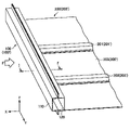
まず、図1を参照して、第1の実施形態に係る構造部材100の概略構成について説明する。図1は、本実施形態に係る構造部材100とその周辺構造の一例を示す斜視図である。図1に示すように、構造部材100は、図1におけるY方向を軸方向とし、軸方向を法線方向とする断面視(X-Z平面視)したときに、閉断面となっている部材である。構造部材100は、第1の部材110と、第2の部材120とを含んで構成されている。構造部材100の閉断面部101の内部には、補強部(図示せず。図2で後述する第1の壁131と第2の壁133に相当)が設けられている。<1. First Embodiment>
[Example of vehicle body structure configuration]
First, with reference to FIG. 1, a schematic configuration of the
図1に示すように、構造部材100は、外部から荷重Fを受ける場合がある。構造部材100は、第1の部材110が当該荷重Fを受けるように配置される。補強部は、当該荷重Fによる構造部材100の変形を抑制しつつ、衝撃吸収特性を向上させるために、設けられる。補強部についての詳細は後述する。
As shown in FIG. 1, the
また、図1に示すように、構造部材100は、車体構造200の一部として構成されてもよい。車体構造200は、構造部材100と、第1のクロス部材201と、第2のクロス部材203とを有する。また、車体構造200は、板状部材205を有してもよい。なお、後述する構造部材100の第1の面111は、車体構造200における車外側と車内側のうち車外側に配置され、第2の面121は車内側に配置される。
Further, as shown in FIG. 1, the
図1に示すように、第1のクロス部材201は、構造部材100に対して荷重Fが入力される側とは反対側の面において、構造部材100の軸方向と略直交する方向(図1におけるX方向)に取り付けられている。また、第2のクロス部材203は、構造部材100へ荷重Fが入力される側とは反対側の面において、第1のクロス部材201と平行な方向に取り付けられている。さらに、第2のクロス部材203は、構造部材100の軸方向において、第1のクロス部材201とは異なる位置に取り付けられている。補強部は、構造部材100の軸方向において、少なくとも第1のクロス部材201と第2のクロス部材203との間に設けられている。
As shown in FIG. 1, the
車体構造200は、自動車のフロア構造であることが好ましい。図1の例におけるフロア構造は、構造部材としてのサイドシル100’と、第1のクロス部材としての第1のフロアクロスメンバ201’と、第2のクロス部材としての第2のフロアクロスメンバ203’と、板状部材としてのフロア205’とを有する。構造部材がサイドシルである場合、後述の第1の面111は車幅方向(図1におけるX方向)の車外側の面であり、第2の面121は車幅方向の車内側の面である。
The
構造部材100は、キャビン骨格または衝撃吸収骨格として自動車骨格を構成し得る。キャビン骨格としての適用例は、特にクロス部材により支持されて曲げ入力が想定される、ルーフサイドレール、Bピラー、Aピラーロア、Aピラーアッパーが挙げられる。また、その他に、構造部材100は、ルーフセンタリンフォース、トンネル、キックリーンフォース、アンダーリーンフォース、フロントヘッダ等に適用されてもよい。
The
また、衝撃吸収骨格としての構造部材100の適用例は、特にクロス部材により支持されて曲げ入力が想定される、バンパリーンフォースが挙げられる。また、その他に、構造部材100は、リアサイドメンバー、エプロンアッパメンバ、バンパリーンフォース、クラッシュボックス、フロントサイドメンバー等に適用されてもよい。
Further, an example of application of the
[構造部材の構成例]
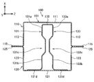
次に、図2を参照して、本実施形態に係る構造部材100の断面構造について説明する。図2は、本実施形態に係る構造部材100の断面構造の一例を示す、図1におけるI-I’断面図である。図2に示すように、構造部材100は、第1の部材110と、第2の部材120と、第1の壁131と、第2の壁133とを備えている。構造部材100は、第1の部材110と第2の部材120とにより、X-Z平面の断面において、閉断面部101が形成されている。構造部材100は、当該閉断面部101の内部に第1の壁131と第2の壁133を備えている。[Structural member configuration example]
Next, with reference to FIG. 2, the cross-sectional structure of the
第1の部材110は、X-Z平面の断面視でハット形状の部材である。詳述すると、第1の部材110は、閉断面部101の第1の面としての天板部111と、天板部111の短手方向(Z方向)の端部に屈曲部を挟んで隣接する縦壁部113と、縦壁部113の天板部111と反対側において別の屈曲部を挟んで隣接するフランジ部115とを有する。第1の部材110は、例えば鋼板のプレス加工等により製造される。
The
天板部111には、構造部材100の外方から荷重Fが入力され得る。荷重Fの入力によって、まず第1の部材110が変形する。このとき、天板部111とともに縦壁部113が面外変形する。このように縦壁部113により、荷重Fが入力された際の、第1の部材110の変形能が向上される。
A load F can be input to the
第2の部材120は、X-Z平面の断面視でハット形状の部材である。詳述すると、第2の部材120は、閉断面部101の第2の面としての天板部121と、天板部121の短手方向(Z方向)の端部に屈曲部を挟んで隣接する縦壁部123と、縦壁部123の天板部121と反対側において別の屈曲部を挟んで隣接するフランジ部125とを有する。第2の部材120は、例えば鋼板のプレス加工等により製造される。
The
第1の部材110と第2の部材120とが、それぞれのフランジ部115、125で互いに接合されるので、構造部材100が閉断面構造になる。接合方法は、レーザ溶接、スポット溶接などの公知の接合技術が用いられ、特に限定されない。
Since the
第1の部材110と、第2の部材120の材質は、例えば、引張強度で980MPa級の鋼材である。また、その他の材質として、例えば、その他の引張強度クラスの鋼材であってもよいし、アルミニウム基合金、マグネシウム基合金等の軽金属合金、CFRP(Carbon Fiber Reinforced Plastic)等の繊維強化樹脂であってもよい。また、第1の部材110と、第2の部材120とは、上記材料を組み合わせて、構成されてもよい。また、第1の部材110、および第2の部材120の板厚は、例えば、1.6mmであるが、特に限定されない。第1の部材110および第2の部材120の材質および板厚は、構造部材100の使用目的、用途等に応じて適宜選択され得る。
The material of the
[第1の壁と第2の壁]
引き続き、図2を参照しながら、本実施形態に係る第1の壁131と第2の壁133について説明する。図2に示すように、第1の壁131と第2の壁133は、構造部材100の閉断面部101の内部において第1の部材110の天板部111と第2の部材120の天板部121の間に設けられている。第1の壁131は、第2の部材120の天板部121から第1の部材110の天板部111に向かって延在している。同様に、第2の壁133は、第2の部材120の天板部121から第1の部材110の天板部111に向かって延在している。これらの第1の壁131と第2の壁133は、構造部材100の軸方向(図1におけるY方向)に延在している。衝撃吸収特性を向上させる観点からは、第1の壁131と第2の壁133は、構造部材100の軸方向(図1におけるY方向)の少なくとも一部において、設けられていればよい。[First wall and second wall]
Subsequently, with reference to FIG. 2, the
構造部材100は、第1の壁131の、第1の部材110の天板部111側端部と、第2の壁133の、第1の部材110の天板部111側端部の間を繋ぐ連結部135を有する。すなわち、X-Z平面断面視で、一対の第1の壁131と第2の壁133は、それぞれのZ方向端部で、連結部135により繋がっている。
The
第1の壁131は、第1の部位131aと、第2の部位131bと、第1の部位131aおよび第2の部位131bよりも第2の壁133に向かって突出した第1の溝部131cを有している。第1の溝部131cは、構造部材100の軸方向(Y方向)に延在している。また、第1の壁131は、図2のように第2の部位131bの端部から、第2の壁133と反対側へ屈曲された第1のフランジ131dを有してもよい。
The
第2の壁133は、第1の部位133aと、第2の部位133bと、第1の部位133aおよび第2の部位133bよりも第1の壁131に向かって突出した第2の溝部133cを有している。第2の溝部133cは、構造部材100の軸方向(Y方向)に延在している。また、第2の壁133は、第2の部位133bの端部から、第1の壁131と反対側へ屈曲された第2のフランジ133dを有してもよい。
The
第1の壁131と第2の壁133の間の距離は、例えば第1の部材110の天板部111の短手方向(Z方向)距離の1/4程度である。
The distance between the
第1の壁131の第1の部位131aは、第1の部材110の天板部111側にある平板状の部位である。第2の壁133の第1の部位133aは、第1の部材110の天板部111側にある平板状の部位である。また、第1の壁131の第2の部位131bは、第2の部材120の天板部121側にある平板状の部位である。第2の壁133の第2の部位133bは、第2の部材120の天板部121側にある平板状の部位である。
The
第1の溝部131cは、第1の壁131の、第1の部位131aと第2の部位131bの間に設けられている。第2の溝部133cは、第2の壁133の、第1の部位133aと第2の部位133bの間に設けられている。第1の溝部131cと第2の溝部133cは、図2におけるX方向で第1の壁131と第2の壁133の略中央に設けられていることが好ましい。換言すると、第1の溝部131cと第2の溝部133cは、中間面101aを横切る位置に設けられていることが好ましい。中間面101aとは、閉断面部101の第1の面(本実施形態では天板部111)と、第2の面(本実施形態では天板部121)の中間に位置する面である。より詳述すると、中間面101aは、第1の面に垂直な方向の第1の面と第2の面の間隔をDとしたときに、D/2の位置にある面である。
The
第1の溝部131cと第2の溝部133cが中間面101aを横切るように設けられていることで、第1の溝部131cと第2の溝部133cを起点として第1の壁131と第2の壁133が変形する際に、第1の壁131と第2の壁133の天板部111側の変形可能な部分を残しつつ、第1の壁131と第2の壁133の天板部121側の部分によって、背面侵入量を抑制することができる。なお、第1の壁131と第2の壁133の変形の詳細については後述する。
Since the
第1の溝部131cの深さ(第1の壁131の第1の部位131aからのZ方向距離)は、少なくとも6mmであることが好ましい。第2の溝部133cの深さ(第2の壁133の第1の部位133aからのZ方向距離)は、少なくとも6mmであることが好ましい。第1の溝部131cの幅(X方向距離)は、第1の壁131のX方向距離に対して、1/4~1/3であることが好ましい。第2の溝部133cの幅(X方向距離)は、第2の壁133のX方向距離に対して、1/4~1/3であることが好ましい。
The depth of the
また、第1の溝部131cと第2の溝部133cの形状は、図2に示したような形状に限定されない。例えば第1の部材110の天板部111への荷重入力後、第1の壁131と第2の壁133の変形開始に伴って、第1の溝部131cと第2の溝部133c同士が接触する形状であればよい。
Further, the shapes of the
本実施形態のように閉断面部101の内部に第1の壁131と第2の壁133が設けられていることにより、構造部材100の変形開始直後から、連結部135を介して第1の壁131と第2の壁133の変形も開始される。従って、第1の壁131と第2の壁133による耐荷重向上や衝撃吸収特性の向上効果が、変形開始初期から発揮される。
Since the
連結部135は、図2のように第1の部材110の天板部111に接触していてもよい。この場合、連結部135は、構造部材100の閉断面部101の内側に溶接等により接合されていてもよい。また、第1の壁131と第2の壁133は、図3のように第1の部材110の天板部111に直接接触または接合されていてもよい。この場合の連結部135とは、第1の部材110の天板部111である。また、連結部135は、図4のように第1の部材110の天板部111に当接していない、天板部111に平行な面であってもよい。図3および図4のような場合であっても、天板部111への荷重入力時には連結部135を介して第1の壁131と第2の壁133が変形することから、第1の壁131と第2の壁133が設けられていない場合に比べて衝撃吸収特性が向上する。
The connecting
第1の壁131は、連結部135に繋がっている端部とは反対側の端部に連続する第1のフランジ131dを有していてもよい。第2の壁133は、連結部135に繋がっている端部とは反対側の端部に連続する第2のフランジ133dを有していてもよい。図2の例において、第1の壁131と第2の壁133は、第2の部材120の天板部121の内側に、第1のフランジ131dと第2のフランジ133dを介して溶接等により取り付けられている。第1の壁131と第2の壁133が第1のフランジ131dと第2のフランジ133dを介して構造部材100の閉断面部101の内側に接合されていることにより、荷重入力時に第1の壁131と第2の壁133が安定して変形できる。
The
なお、第1の壁131と第2の壁133は、第1のフランジ131dと第2のフランジ133dを介さずに、第1の壁131と第2の壁133の端部が第2の部材120の閉断面部101の内側に直接突き当てられた状態で、溶接等によって接合されていてもよい。
In the
第1の壁131と第2の壁133の材質は、衝撃吸収特性、変形特性に応じて、適宜変更でき、特に限定されない。例えば、引張強度で980MPa級の鋼材や、その他の引張強度クラスの鋼材であってもよいし、アルミニウム基合金、マグネシウム基合金等の軽金属合金、CFRP等の繊維強化樹脂であってもよい。また、第1の壁131と第2の壁133の材質は、第1の部材110または第2の部材120と同一の材料であってもよいし、異なる材質であってもよい。
The materials of the
また、第1の壁131と第2の壁133の板厚についても、衝撃吸収特性、変形特性に応じて、適宜変更でき、特に限定されない。例えば、第1の壁131と第2の壁133の板厚は、1.6mm程度である。また、例えば、第1の壁131と第2の壁133の板厚は、第1の部材110または第2の部材120と同一または異なる板厚であってもよい。以上、本実施形態に係る構造部材100の構成例について説明した。
Further, the plate thicknesses of the
[構造部材の変形]
次に、図5A、図5Bを参照して、本実施形態に係る構造部材100に荷重がかかったときの変形の様子について説明する。図5Aは、本実施形態に係る構造部材100に荷重がかかったときの変形の様子を模式的に示す図である。図5Bは、本実施形態に係る構造部材100に荷重がかかったときの変形の様子を模式的に示す図である。図5Aに示すように、例えば荷重Fが、構造部材100の天板部111に対して入力される。このとき、第1の部材110の縦壁部113が面外変形するとともに、第1の壁131と第2の壁133が変形する。[Deformation of structural members]
Next, with reference to FIGS. 5A and 5B, a state of deformation when a load is applied to the
具体的には、第1の壁131と第2の壁133に第1の部材110の天板部111から荷重が伝達されると、第1の壁131と第2の壁133の第1の部位131a、133a、および連結部135が外方に膨らむようにして変形する。また、第1の壁131の第1の溝部131cと、第2の壁133の第2の溝部133c同士が接触する方向に変形する。その後、第1の壁131と第2の壁133は、連結部135側から次第に押し潰されるように変形する。このとき、第1の溝部131cと第2の溝部133c同士は接触しているので、第1の壁131と第2の壁133の第1の部材110側(第1の部位131a、133a、連結部135)での変形が主に進行する。すなわち、第1の溝部131cと第2の溝部133c同士が接触することにより、入力荷重に対して第1の部位131a、133aが図5AにおけるX方向に支持され、当該部位のみを選択的に変形させることができる。
Specifically, when a load is transmitted from the
この結果、図5Aに示すように、第1の部材110側の変形が進む一方で、第2の部材120側では、大きな変形が生じない。このように、構造部材100の衝撃吸収特性が向上しつつ、第1の部材110側という特定部位のみで変形を進行させることができる。
As a result, as shown in FIG. 5A, the deformation on the
さらに、変形が進むと、図5Bに示すように、第1の部材110は、大きく変形し、特に縦壁部113が著しく面外変形している。一方、第2の部材120も大きく変形しているが、第1の部材110と比較すれば、変形はある程度抑制されている。また、第1の壁131と第2の壁133の第1の部材110側は、ほぼ圧潰し、第1の壁131と第2の壁133の第2の部材120側も部分的に変形している。さらに、第1の壁131と第2の壁133が全体として図5B中のZ方向へ倒れるように変形している(図中矢印参照)。これは、第1の壁131と第2の壁133に生じた荷重Fによる曲げモーメントとの影響と考えられる。以上、本実施形態に係る構造部材100の変形の様子について説明した。
Further, as the deformation progresses, as shown in FIG. 5B, the
(作用効果)
本実施形態によれば、構造部材100の第1の溝部131cと第2の溝部133c同士の接触により、第1の壁131と第2の壁133の変形が部分的に抑制され、耐荷重が向上するとともに、一方、第1の部材110側の変形が進行し、変形能が向上する。この結果、構造部材100の衝撃吸収特性が向上する。(Action effect)
According to the present embodiment, the contact between the
特に、近年普及が進んでいる電気自動車やハイブリッド自動車等に搭載されているLiイオンバッテリモジュールは、自動車のフロア構造内に配置されていることがある。この場合、側面衝突により、フロア側方の構造部材(サイドシル等)が大きく変形すると構造内部へ侵入することがある。そこで、バッテリモジュールの安全性をさらに向上させるため、構造部材の侵入量(背面侵入量)を抑制することが求められる。 In particular, the Li-ion battery module mounted on an electric vehicle, a hybrid vehicle, or the like, which has become widespread in recent years, may be arranged in the floor structure of the vehicle. In this case, if the structural member (side sill or the like) on the side of the floor is significantly deformed due to a side collision, it may invade the inside of the structure. Therefore, in order to further improve the safety of the battery module, it is required to suppress the intrusion amount (rear intrusion amount) of the structural member.
本実施形態に係る構造部材100によれば、上述の様に、第1の部材110側を変形させて、第2の部材120側の変形を抑制できるので、背面侵入量を抑制することができる。特に、本実施形態に係る車体構造200が、フロア構造である場合に、構造内部への背面侵入量を抑制することができる。これにより、フロア構造内に配置されるLiイオンバッテリモジュール等の部品を保護し、安全性をさらに向上できる。
According to the
[変形例]
次に、図6を参照しながら、上記実施形態の一の変形例について説明する。図6は、本実施形態に係る構造部材100の一の変形例を示す断面図である。図2の例では、第1の壁131と第2の壁133の、天板部121側の端部に第1のフランジ131dと第2のフランジ133dが設けられていたが、図6のように第1のフランジ131dと第2のフランジ133dは設けられていなくてもよい。本変形例によれば、図6におけるX-Z平面断面視で、第1の壁131と第2の壁133の形状が、第1の部材110側と第2の部材120側とで対称となっている。[Modification example]
Next, a modified example of the above embodiment will be described with reference to FIG. FIG. 6 is a cross-sectional view showing a modified example of one of the
<2.第2の実施形態>
次に、図7~図9を参照しながら、第2の実施形態に係る構造部材100について説明する。図7は、第2の実施形態に係る構造部材100とその周辺構造の一例を示す斜視図である。図8は、本実施形態に係る構造部材100の第1の溝部131cと第2の溝部133cの断面構造の一例を示す、図7におけるII-II’端面図である。図9は、本実施形態に係る構造部材100の断面構造の一例を示す、図7におけるIII-III’端面図である。本実施形態の構造部材100は、補強部材140を有している。本実施形態の構造部材100は、第1の溝部131cと第2の溝部133c同士が接触するまでの第1の壁131と第2の壁133の変形が抑制される点で、上述した第1の実施形態と相違する。なお、本実施形態において、第1の実施形態と共通する構成については説明を省略することがある。<2. Second embodiment>
Next, the
図7~図9に示すように、本実施形態に係る構造部材100は、第1の壁131の第1の溝部131cと第2の壁133の第2の溝部133cとの間に、補強部材140を備えている。
As shown in FIGS. 7 to 9, the
図8に示すように、補強部材140は、第1の壁131の第1の溝部131cと、第2の壁133の第2の溝部133cとの間に配置された、複数の壁部141を有する。壁部141は、第1の溝部131cと第2の溝部133c同士の接触方向(図8におけるZ方向)が、壁部141の面内方向に略一致するまたは、所定の角度を有するように延在されている。すなわち、壁部141は、第1の壁131の第1の溝部131cと、第2の壁133の第2の溝部133cとの間を架け渡すように配置されている。これにより、第1の溝部131cと第2の溝部133c同士が接触するように変形する際の第1の壁131と第2の壁133の耐荷重を向上できる。
As shown in FIG. 8, the reinforcing
本実施形態の補強部材140は、第1の平面部143aと、第2の平面部143bと、第1の接合部145aと、第2の接合部145bを備えている。第1の平面部143aと第2の平面部143bの間には壁部141がある。第1の接合部145aでは、第1の平面部143aと第1の壁131の第1の溝部131cが接合され、第2の接合部145bでは、第2の平面部143bと第2の壁133の第2の溝部133cが接合されている。なお、第1の平面部143aと第2の平面部143bは設けられていなくてもよく、その場合、第1の接合部145aでは、補強部材140の第1面と第1の溝部131cが接合され、第2の接合部145bでは、補強部材140の第1面とは反対側の第2面と第2の溝部133cが接合されていることが好ましい。
The reinforcing
第1の平面部143aは、第1の溝部131cに溶接によって取り付けられ、第2の平面部143bは、第2の溝部133cに溶接によって取り付けられてもよい。このとき、溶接個所に対向する第1の溝部131cと第2の溝部133cには、当該溶接個所に対応する位置に第1の孔部139aと第2の孔部139bが設けられていてもよい。詳述すると、補強部材140は、図8に示すように第2の平面部143bと向き合う第1の溝部131cに第1の孔部139aを備え、第1の平面部143aと向き合う第2の溝部133cに第2の孔部139bを備えていてもよい。第1の孔部139aと第2の孔部139bは、溶接用の工具(例えば、スポット溶接の際の溶接ガン)が通過できる程度の開口面積を有している。第1の孔部139aと第2の孔部139bにより、スポット溶接の際の施工性が向上し、補強部材140が、簡便に第1の壁131と第2の壁133に取り付けられる。
The first
また、補強部材140は、図8におけるX方向視で波形状を有していてもよい。すなわち、補強部材140は、第1の壁131の第1の溝部131cと、第2の壁133の第2の溝部133cが対向する方向(図8のZ方向)に沿って振幅を有する波形状を有していてもよい。これにより、壁部141と第1の平面部143aと第2の平面部143bの数を多くすることができ、補強部材140による、第1の溝部131cと第2の溝部133c同士の連結を効率的かつ強固に行うことができる。このとき、補強部材140の溶接個所Wは、補強部材140の所定の波長Lの半分に対応する間隔で形成されてもよい。すなわち、補強部材140は、振幅が最大となる半波長位置であるL/2ごとに、第1の壁131の第1の溝部131cと、第2の壁133の第2の溝部133cと交互に溶接されている。
Further, the reinforcing
さらに、第1の孔部139aは、第2の接合部145bの間隔に対応するように第1の溝部131cに設けられている。また、第2の孔部139bは、第1の接合部145aの間隔に対応するように第2の溝部133cに設けられている。すなわち、第1の孔部139aと第2の孔部139bは、補強部材140の振幅が最大となる半波長位置であるL/2ごとに、第1の壁131の第1の溝部131cと、第2の壁133の第2の溝部133cに交互に設けられている。
Further, the
[構造部材の変形]
次に、図10を参照して、本実施形態に係る構造部材100に荷重がかかったときの変形の様子について説明する。図10は、本実施形態に係る構造部材100に荷重がかかったときの変形の様子を模式的に示す図である。図10に示すように、例えば荷重Fが第1の部材110の天板部111に入力され、変形が進むと、第1の部材110は、大きく変形し、特に縦壁部113が著しく面外変形している。一方、第2の部材120も大きく変形しているが、第1の部材110と比較すれば、変形はある程度抑制されている。また、第1の壁131と第2の壁133の第1の部材110側は、ほぼ圧潰し、第1の壁131と第2の壁133の第2の部材120側も部分的に変形している。[Deformation of structural members]
Next, with reference to FIG. 10, the state of deformation when a load is applied to the
ここで、本実施形態においては、第1の壁131と第2の壁133は、図5Bに示したような第1の壁131と第2の壁133が全体としてZ方向へ倒れるような変形を示していない。これは、第1の孔部139aが、第2の接合部145bに対応する位置に一定の間隔で設けられ、第2の孔部139bが第1の接合部145aに対応する位置に一定の間隔で設けられていることによる。すなわち、第1の孔部139aと第2の孔部139bが、均等に設けられていることで、荷重Fにより第1の壁131と第2の壁133に生じる曲げモーメントの影響が、第1の壁131と、第2の壁133との間で互いに打ち消し合うと考えられる。すなわち、荷重Fにより第1の壁131に生じる曲げモーメントと、第2の壁133に生じる曲げモーメントとが互いに反対であり、打ち消し合うように働く。この結果、第1の壁131と第2の壁133において、図9におけるZ方向に倒れる変形が抑制され、変形が安定化する効果が生じたと考えられる。
Here, in the present embodiment, the
(作用効果)
本実施形態によれば、補強部材140により、第1の溝部131cと第2の溝部133c同士が接触するまでの第1の壁131と第2の壁133の変形が抑制される。これにより、第1の壁131と第2の壁133の変形が部分的に抑制され、耐荷重が向上するとともに、一方、第1の部材110側の変形が進行し、変形能が向上する。この結果、構造部材100の衝撃吸収特性が向上する。以上、第2の実施形態に係る構造部材100について説明した。(Action effect)
According to the present embodiment, the reinforcing
なお、補強部材140の形状は、第1の溝部131cと第2の溝部133c同士が接触するまでの第1の溝部131cと第2の溝部133cの変形を抑制できればよく、特に限定されない。例えば、補強部材140は、中空もしくは中実の棒状、板状、または中空もしくは中実の箱形状の部材であり、第1の溝部131cと第2の溝部133cの間に構造部材100の軸方向(図6におけるY方向)に沿って設けられてもよい。すなわち、補強部材140が、第1の溝部131cと第2の溝部133cの間に配置され、かつ、第1の溝部131cまたは第2の溝部133cに接合されていれば、第2の実施形態のように衝撃吸収特性を向上させることができる。また、補強部材140の材質は、鋼材、軽金属、繊維強化樹脂、または、軟質もしくは硬質樹脂等であってもよい。
The shape of the reinforcing
なお、補強部材140の波形状は、矩形波状に限定されない。例えば、補強部材140の波形状は、変形特性に応じて、種々の波長、位相または振幅を有する波形状を採り得る。
The wave shape of the reinforcing
<3.第3の実施形態>
次に、図11~図12を参照しながら、第3の実施形態に係る構造部材100について説明する。図11は、第3の実施形態に係る構造部材の軸方向の断面構造の一例を示す図である。図12は、同実施形態に係る構造部材の断面構造の一例を示す、図11におけるIV-IV’端面図である。本実施形態の構造部材100は、第1の壁131と、第2の壁133と、二つの第3の壁150を備えている。第3の壁150は、構造部材100の軸方向(Y方向)に延在している。本実施形態の第3の壁150は板形状である。本実施形態においては、第3の壁150のZ方向の端部150a、150bのうち、端部150aは第1の溝部131cに接合されることで互いに繋がっており、端部150bは第2の溝部133cに接合されることで互いに繋がっている。第1の溝部131cと第2の溝部133cに対する第3の壁150の接合方法は特に限定されない。<3. Third Embodiment>
Next, the
本実施形態の構造部材100においては、第3の壁150が設けられていることによって、第2の実施形態の構造部材100と同様に第1の溝部131cと第2の溝部133cが接触するまでの第1の壁131と第2の壁133の変形が抑制される。これにより、第1の壁131と第2の壁133の変形が部分的に抑制され、耐荷重を向上させることができ、衝撃吸収特性が向上する。
In the
構造部材100は、図11のように第3の壁150を複数備えていることが好ましい。第3の壁150が一つだけ設けられている場合には、構造部材100への荷重入力時に、例えば第3の壁150の端部150aを回転中心とした曲げモーメントが発生し、第1の溝部131cと第2の溝部133c同士が接触するまでの変形を抑制する効果が小さい。一方、第3の壁150が二つ以上設けられていれば、一つの第3の壁150で生じる上記のような曲げモーメントによる変形を他の第3の壁150で抑制することができる。これにより、第1の溝部131cと第2の溝部133cが接触するまでの第1の壁131と第2の壁133の変形強度が大きくなり、耐荷重が向上する。
It is preferable that the
本実施形態の第3の壁150は、構造部材100の第1の面に対して傾斜していたが、第1の面に平行であってもよい。また、本実施形態の第3の壁150の形状が板形状であったが、第3の壁150の形状は特に限定されない。第3の壁150の材質は、鋼材、軽金属、繊維強化樹脂、または、軟質もしくは硬質樹脂等であってもよい。
The
構造部材100について性能を確認するため、構造部材100に対し、3点曲げのシミュレーションを実施した。比較例1は、第1の部材110と第2の部材120のみからなる構造部材とした。また、比較例2は、溝部を有さない第1の壁と第2の壁を有する構造部材とした。実施例1は、前述の第1の実施形態に係る構造部材100とした。
In order to confirm the performance of the
比較例1の第1の部材と第2の部材とは、いずれも引張強度で980MPa級の板厚1.8mmの鋼板とした。比較例2の第1の部材と第2の部材とは引張強度で980MPa級の板厚1.4mmの鋼板とし、補強部材は引張強度で980MPa級の板厚1.6mmの鋼板とした。実施例は、比較例2と同じ鋼板で構成されるものとした。 The first member and the second member of Comparative Example 1 were both steel plates having a tensile strength of 980 MPa and a plate thickness of 1.8 mm. The first member and the second member of Comparative Example 2 were steel plates having a tensile strength of 980 MPa class and a plate thickness of 1.4 mm, and the reinforcing members were steel plates having a tensile strength of 980 MPa class and a plate thickness of 1.6 mm. The example was made of the same steel plate as in Comparative Example 2.
3点曲げ試験のシミュレーション条件について、図13Aおよび図13Bを参照しながら説明する。図13Aおよび図13Bは、シミュレーション解析の条件の一例を説明するための図である。すなわち、図13Aに示すように、3点曲げの圧子P(ポール)の直径φは、254mmとし、ポールを所定の速度で構造部材の第1の部材110の荷重入力面111に向けて移動させた(図中矢印参照)。構造部材の第2の部材120側の2つの剛体支持点G1、G2の間隔tは300mmとし、2つの剛体支持点G1、G2の中間点にポールを衝突させた。ポールと構造部材との間に発生する荷重およびポール中央位置での第1の部材110への背面侵入量(δb)を計測した。
The simulation conditions of the three-point bending test will be described with reference to FIGS. 13A and 13B. 13A and 13B are diagrams for explaining an example of the conditions for simulation analysis. That is, as shown in FIG. 13A, the diameter φ of the indenter P (pole) for three-point bending is 254 mm, and the pole is moved at a predetermined speed toward the
ここで、背面侵入量δbは構造部材の荷重入力面とは反対側への侵入量の評価値であり、この値が小さいほど、構造部材の荷重入力面とは反対側への侵入量が抑制されていることを意味する。具体的には、図13Bに示すように、ポール衝突前の第2の部材120の天板部(2つの剛体支持点で支持される面)の荷重入力方向の初期位置と、変形に伴う第2の部材120の天板部の荷重入力方向の位置との差である。
Here, the back surface intrusion amount δb is an evaluation value of the intrusion amount of the structural member to the side opposite to the load input surface, and the smaller this value is, the more the intrusion amount of the structural member to the side opposite to the load input surface is suppressed. It means that it has been done. Specifically, as shown in FIG. 13B, the initial position in the load input direction of the top plate portion (the surface supported by the two rigid body support points) of the
図14Aは、3点曲げシミュレーションにおける構造部材のポール変位と背面侵入量比の関係を示すグラフである。背面侵入量(δb)比は、各測定結果を比較例1の背面侵入量δbの最大値で規格化した値である。図14Aに示すように、比較例1に比べ、凹部のない補強部材を有する比較例2は、背面侵入量(δb)比が2倍程度になっており、荷重入力面と反対側に構造部材が大きく侵入した。一方、本実施形態に係る第1の壁131と第2の壁133を有する実施例1は、比較例1と同程度の背面侵入量(δb)比であった。従って、本実施形態に係る構造部材100は、荷重入力面111と反対側への侵入量が抑制されることが示された。さらに、実施例の構造部材100の板厚が、1.6mmであり、比較例1の板厚は1.8mmであったことから、本実施形態に係る構造部材100は、軽量化を実現できることも示された。
FIG. 14A is a graph showing the relationship between the pole displacement of the structural member and the back penetration amount ratio in the three-point bending simulation. The back penetration amount (δb) ratio is a value obtained by normalizing each measurement result with the maximum value of the back penetration amount δb of Comparative Example 1. As shown in FIG. 14A, compared to Comparative Example 1, Comparative Example 2 having a reinforcing member having no recess has a back surface penetration amount (δb) ratio of about twice, and the structural member is on the opposite side to the load input surface. Invaded greatly. On the other hand, Example 1 having the
また、図14Bは、3点曲げシミュレーションにおける構造部材のポール変位と荷重比の関係を示すグラフである。荷重比は、ポール衝突時の入力荷重の測定結果を、比較例1の荷重の最大値で規格化したものである。図14Bに示すように、実施例1の荷重比は、比較例1に比べ高く、耐荷重が向上した。さらに、実施例1は、溝部のない第1の壁と第2の壁を有する比較例2と同程度である。このことから本実施形態に係る構造部材100は高い荷重で変形することが示された。
Further, FIG. 14B is a graph showing the relationship between the pole displacement of the structural member and the load ratio in the three-point bending simulation. The load ratio is a standardization of the measurement result of the input load at the time of pole collision with the maximum value of the load of Comparative Example 1. As shown in FIG. 14B, the load ratio of Example 1 was higher than that of Comparative Example 1, and the load capacity was improved. Further, Example 1 is similar to Comparative Example 2 having a first wall without a groove and a second wall. From this, it was shown that the
次に、構造部材のエネルギー吸収量(EA)について評価した。ここで、エネルギー吸収量EAはポール変位に対する荷重の積分値とした。エネルギー吸収量EAを構造部材の質量で除し、さらに背面侵入量δbで除したEA/質量/δbという値を評価値とし、比較する。この指標が大きいほど、高い衝撃吸収性能の質量効率と構造部材の侵入量抑制を両立した構造を意味する。比較結果を表1に示した。表1中の値は比較例1の値で規格化している。 Next, the energy absorption amount (EA) of the structural member was evaluated. Here, the energy absorption amount EA is an integral value of the load with respect to the pole displacement. The value of EA / mass / δb obtained by dividing the energy absorption amount EA by the mass of the structural member and further dividing by the back penetration amount δb is used as an evaluation value for comparison. The larger this index is, the more the mass efficiency of high impact absorption performance and the suppression of the intrusion amount of structural members are compatible with each other. The comparison results are shown in Table 1. The values in Table 1 are standardized by the values of Comparative Example 1.

表1に示すように、EA/質量/δb比の値は、比較例1、2と比較して、実施例1が著しく高かった。このことから、本実施形態に係る構造部材100は、高い衝撃吸収性能の質量効率と背面侵入量δbの抑制を両立していることが示された。
As shown in Table 1, the value of the EA / mass / δb ratio was significantly higher in Example 1 than in Comparative Examples 1 and 2. From this, it was shown that the
次に、構造部材100の衝撃吸収特性に第1の壁131と第2の壁133が与える影響を評価するため、実施例1~3を比較した。実施例2は、補強部材140を備える構造部材100とした。また、実施例3は、補強部材140を有し、さらに溶接個所に対応する位置に第1の孔部139aと第2の孔部139bを備える構造部材100とした。実施例1~3について、エネルギー吸収量(EA)比、背面侵入量(δb)比で比較した結果を表2に示す。EA比、δb比のいずれも測定結果を比較例1の値で規格化したものである。
Next, in order to evaluate the influence of the

実施例2と実施例3の背面侵入量(δb)比は、実施例1と同程度であった。一方で、実施例2と実施例3は、実施例1に比べエネルギー吸収量(EA)比が高かった。このことから、補強部材140によって、構造部材100の衝撃吸収性能が高まることが示された。また、実施例2と実施例3とを比較すると、実施例3の背面侵入量(δb)比が、実施例2に対して低減された。これは、第1の孔部139aと第2の孔部139bが均等に配置された結果、第1の壁131と第2の壁133が倒れるように変形する曲げモーメントが抑制され、衝撃吸収効果が向上したためと考えられる。このように、第1の孔部139aと第2の孔部139bを備える構造部材100により、背面侵入量がより抑制されることが示された。
The back penetration amount (δb) ratio of Example 2 and Example 3 was about the same as that of Example 1. On the other hand, in Example 2 and Example 3, the energy absorption amount (EA) ratio was higher than that in Example 1. From this, it was shown that the reinforcing
以上、添付図面を参照しながら本開示の好適な実施形態について詳細に説明したが、本開示はかかる例に限定されない。本開示の属する技術の分野における通常の知識を有する者であれば、特許請求の範囲に記載された技術的思想の範疇内において、各種の変更例または修正例に想到し得ることは明らかであり、これらについても、当然に本開示の技術的範囲に属するものと了解される。 Although the preferred embodiments of the present disclosure have been described in detail with reference to the accompanying drawings, the present disclosure is not limited to such examples. It is clear that anyone with ordinary knowledge in the field of the art to which this disclosure belongs can come up with various modifications or amendments within the scope of the technical ideas set forth in the claims. , These are also naturally understood to belong to the technical scope of the present disclosure.
例えば、上記実施形態では、第1の部材110をハット形状としたが、第1の部材110はかかる例に限定されない。第1の部材110は、構造部材100を形成するための形状を有していればよく、断面視でコの字形状、円弧形状等でもよい。また、第1の部材110は、断面視で部分的に屈曲されてもよいし、ビード形状等の凹凸を有してもよい。
For example, in the above embodiment, the
また、上記実施形態では、第2の部材120をハット形状としたが、第2の部材120はかかる例に限定されない。第2の部材120は、板状部材でもよい。すなわち、第1の部材が、断面視略ハット形状を有し、第2の部材がクロージングプレートである、いわゆる片ハット形状の構造部材100でもよい。また、第2の部材120は、断面視で部分的に屈曲されてもよいし、ビード形状等の凹凸を有してもよい。
Further, in the above embodiment, the
また、上記実施形態では、第1の部材110と第2の部材120とがフランジ部115、125を介して溶接されるとしたが、第1の部材110と第2の部材120の溶接位置はかかる例に限定されない。例えば、第1の部材110と第2の部材120とは、略ハット形状の縦壁部113、123の端部付近で溶接されるようにしてもよい。
Further, in the above embodiment, the
また、上記実施形態において、第1の部材110と、第2の部材120の他に、構造部材100の外形を成す部材が含まれてもよい。さらに、第1の部材110と第2の部材120との間に別の部材が、設けられてもよい。また、カバー部材により、第1の部材110と、第2の部材120とが外方から覆われてもよい。
Further, in the above embodiment, in addition to the
上記実施形態では、構造部材100の閉断面部101が第1の部材110と第2の部材120で構成されていたが、閉断面部101は、図15に示すように例えば角筒状の中空部材105で構成されていてもよい。図15の例においては、第1の壁131と第2の壁133は構造部材100の第1の面111と第2の面121に繋がっている。図15の例においては、第1の壁131と第2の壁133を繋ぐ連結部135は、第1の面111である。このような構造部材100は例えば押出成形によって製造される。中空部材105の材質は、例えば、引張強度で980MPa級の鋼材である。また、その他の材質として、例えば、その他の引張強度クラスの鋼材であってもよいし、アルミニウム基合金、マグネシウム基合金等の軽金属合金、CFRP等の繊維強化樹脂であってもよい。
In the above embodiment, the
閉断面部101が中空部材105で構成される場合、構造部材100は、例えば図16や図17等に示す構造であってもよい。図16の例における構造部材100は、第1の壁131と第2の壁133が第1の面111に繋がっておらず、第1の壁131と第2の壁133は閉断面部101の第1の面111に平行な面である連結部135を介して繋がっている。図17の例における構造部材100は、図11に示す構造と同様に第1の壁131と、第2の壁133と、複数の第3の壁150を備えている。
When the
以上のように、閉断面部101が中空部材105で構成される場合であっても、閉断面部101内の構造は第1~第3の実施形態のような構造が適用され得る。
As described above, even when the
100 構造部材
101 閉断面部
101a 中間面
105 中空部材
110 第1の部材
111 天板部(閉断面部の第1の面)
120 第2の部材
121 天板部(閉断面部の第2の面)
131 第1の壁
133 第2の壁
131c 第1の溝部
133c 第2の溝部
131d 第1のフランジ
133d 第2のフランジ
135 連結部
139a 第1の孔部
139b 第2の孔部
140 補強部材
141 壁部
143a 第1の平面部
143b 第2の平面部
145a 第1の接合部
145b 第2の接合部
150 第3の壁100
120
131
Claims (16)
前記閉断面部の内部に第1の壁と第2の壁を備え、
前記閉断面部は、第1の面と第2の面を備え、
前記第1の面と前記第2の面は、対向し、
前記第1の壁と前記第2の壁は、前記第2の面から前記第1の面に向かって延在し、
前記第1の壁と前記第2の壁は、前記閉断面部の軸方向に延在し、
前記第1の壁は、前記第2の壁に向かって突出した、前記軸方向に延在する第1の溝部を備え、
前記第2の壁は、前記第1の壁に向かって突出した、前記軸方向に延在する第2の溝部を備え、
前記第1の壁の前記第1の面側の端部と前記第2の壁の前記第1の面側の端部は、連結部を介して繋がっていて、
前記第1の壁の前記第2の面側の端部と前記第2の壁の前記第2の面側の端部は、それぞれ前記第2の面と繋がっていて、
板形状の補強部材をさらに備え、
前記補強部材は、前記第1の溝部と前記第2の溝部の間に配置され、
前記補強部材の第1面と前記第1の溝部を接合している第1の接合部を備え、
前記補強部材の第2面と前記第2の溝部を接合している第2の接合部を備える、構造部材。 With a closed cross section,
A first wall and a second wall are provided inside the closed cross section.
The closed cross section comprises a first surface and a second surface.
The first surface and the second surface face each other,
The first wall and the second wall extend from the second surface toward the first surface.
The first wall and the second wall extend in the axial direction of the closed cross section, and the first wall and the second wall extend in the axial direction.
The first wall comprises a axially extending first groove projecting towards the second wall.
The second wall comprises a second axially extending groove projecting towards the first wall.
The end of the first wall on the first surface side and the end of the second wall on the first surface side are connected via a connecting portion.
The end of the first wall on the second surface side and the end of the second wall on the second surface side are connected to the second surface, respectively.
Further equipped with a plate-shaped reinforcing member,
The reinforcing member is arranged between the first groove portion and the second groove portion.
A first joint portion for joining the first surface of the reinforcing member and the first groove portion is provided.
A structural member including a second joint portion that joins the second surface of the reinforcing member and the second groove portion.
前記第2の壁の前記第2の面側の端部に連続している第2のフランジを備え、
前記第1のフランジと前記第2のフランジは、それぞれ前記第2の面と接合している、請求項1の構造部材。 The first wall is provided with a continuous first flange at the end of the second face side.
The second wall is provided with a continuous second flange at the end of the second face side.
The structural member according to claim 1, wherein the first flange and the second flange are joined to the second surface, respectively.
前記閉断面部の内部に第1の壁と第2の壁を備え、
前記閉断面部は、第1の面と第2の面と第3の面と第4の面とを備え、
前記第1の面と前記第2の面は、対向し、
前記第3の面と前記第4の面は、対向し、
前記第3の面と前記第4の面は、前記第2の面から前記第1の面に向かって延在し、
前記第1の壁と前記第2の壁は、前記第2の面から前記第1の面に向かって延在し、
前記第1の壁と前記第2の壁は、前記閉断面部の軸方向に延在し、
前記第1の壁は、前記第2の壁に向かって突出した、前記軸方向に延在する第1の溝部を備え、
前記第2の壁は、前記第1の壁に向かって突出した、前記軸方向に延在する第2の溝部を備え、
前記第1の壁の前記第1の面側の端部と前記第2の壁の前記第1の面側の端部は、連結部を介して繋がっていて、
前記第1の壁の前記第2の面側の端部に連続している第1のフランジを備え、
前記第2の壁の前記第2の面側の端部に連続している第2のフランジを備え、
前記第1のフランジと前記第2のフランジは、それぞれ前記第2の面と接合し、
前記第1の壁と前記第2の壁は、それぞれ前記第3の面および前記第4の面に接していない、構造部材。 With a closed cross section,
A first wall and a second wall are provided inside the closed cross section.
The closed cross-section portion comprises a first surface, a second surface, a third surface, and a fourth surface.
The first surface and the second surface face each other,
The third surface and the fourth surface face each other,
The third surface and the fourth surface extend from the second surface toward the first surface.
The first wall and the second wall extend from the second surface toward the first surface.
The first wall and the second wall extend in the axial direction of the closed cross section, and the first wall and the second wall extend in the axial direction.
The first wall comprises a axially extending first groove projecting towards the second wall.
The second wall comprises a second axially extending groove projecting towards the first wall.
The end of the first wall on the first surface side and the end of the second wall on the first surface side are connected via a connecting portion.
The first wall is provided with a continuous first flange at the end of the second face side.
The second wall is provided with a continuous second flange at the end of the second face side.
The first flange and the second flange are respectively joined to the second surface.
A structural member in which the first wall and the second wall are not in contact with the third surface and the fourth surface, respectively.
前記補強部材は、前記第1の溝部と前記第2の溝部の間に配置され、
前記補強部材は、前記第1の溝部に接合される、請求項3の構造部材。 Equipped with reinforcing members
The reinforcing member is arranged between the first groove portion and the second groove portion.
The structural member according to claim 3, wherein the reinforcing member is joined to the first groove portion.
前記補強部材の第1面と前記第1の溝部を接合している第1の接合部を備え、
前記補強部材の第2面と前記第2の溝部を接合している第2の接合部を備える、請求項4の構造部材。 The reinforcing member has a plate shape and has a plate shape.
A first joint portion for joining the first surface of the reinforcing member and the first groove portion is provided.
The structural member according to claim 4, further comprising a second joint portion that joins the second surface of the reinforcing member and the second groove portion.
前記第2の接合部は、前記補強部材の第2の平面部と前記第2の溝部を接合し、
前記第1の平面部と向き合う前記第2の溝部には第2の孔部があり、
前記第2の平面部と向き合う前記第1の溝部には第1の孔部がある、請求項1、2または5の構造部材。 The first joint portion joins the first flat surface portion of the reinforcing member and the first groove portion.
The second joint portion joins the second flat surface portion of the reinforcing member and the second groove portion.
The second groove portion facing the first flat surface portion has a second hole portion.
The structural member according to claim 1, 2 or 5, wherein the first groove portion facing the second flat surface portion has a first hole portion.
前記第3の壁は、前記軸方向に延在し、
前記第3の壁の端部は、前記第1の溝部と前記第2の溝部に繋がっている、請求項3の構造部材。 With multiple third walls,
The third wall extends in the axial direction and extends.
The structural member according to claim 3, wherein the end portion of the third wall is connected to the first groove portion and the second groove portion.
前記閉断面部の内部に第1の壁と第2の壁を備え、
前記閉断面部は、第1の面と第2の面を備え、
前記第1の面と前記第2の面は、対向し、
前記第1の壁と前記第2の壁は、前記第2の面から前記第1の面に向かって延在し、
前記第1の壁と前記第2の壁は、前記閉断面部の軸方向に延在し、
前記第1の壁は、前記第2の壁に向かって突出した、前記軸方向に延在する第1の溝部を備え、
前記第2の壁は、前記第1の壁に向かって突出した、前記軸方向に延在する第2の溝部を備え、
前記第1の壁の前記第1の面側の端部と前記第2の壁の前記第1の面側の端部は、連結部を介して繋がっていて、
前記連結部は、前記第1の面に平行な面であり、
前記第1の壁の前記第2の面側の端部に連続している第1のフランジを備え、
前記第2の壁の前記第2の面側の端部に連続している第2のフランジを備え、
前記第1のフランジと前記第2のフランジは、それぞれ前記第2の面と接合している、構造部材。 With a closed cross section,
A first wall and a second wall are provided inside the closed cross section.
The closed cross section comprises a first surface and a second surface.
The first surface and the second surface face each other,
The first wall and the second wall extend from the second surface toward the first surface.
The first wall and the second wall extend in the axial direction of the closed cross section, and the first wall and the second wall extend in the axial direction.
The first wall comprises a axially extending first groove projecting towards the second wall.
The second wall comprises a second axially extending groove projecting towards the first wall.
The end of the first wall on the first surface side and the end of the second wall on the first surface side are connected via a connecting portion.
The connecting portion is a plane parallel to the first plane.
The first wall is provided with a continuous first flange at the end of the second face side.
The second wall is provided with a continuous second flange at the end of the second face side.
A structural member in which the first flange and the second flange are joined to the second surface, respectively.
前記補強部材は、前記第1の溝部と前記第2の溝部の間に配置され、
前記補強部材は、前記第1の溝部に接合される、請求項10の構造部材。 Equipped with reinforcing members
The reinforcing member is arranged between the first groove portion and the second groove portion.
The structural member according to claim 10, wherein the reinforcing member is joined to the first groove portion.
前記第3の壁は、前記軸方向に延在し、
前記第3の壁の端部は、前記第1の溝部と前記第2の溝部に繋がっている、請求項10の構造部材。 With multiple third walls,
The third wall extends in the axial direction and extends.
The structural member according to claim 10, wherein the end portion of the third wall is connected to the first groove portion and the second groove portion.
前記閉断面部の内部に第1の壁と第2の壁を備え、
前記閉断面部は、第1の面と第2の面を備え、
前記第1の面と前記第2の面は、対向し、
前記第1の壁と前記第2の壁は、前記第2の面から前記第1の面に向かって延在し、
前記第1の壁と前記第2の壁は、前記閉断面部の軸方向に延在し、
前記第1の壁は、前記第2の壁に向かって突出した、前記軸方向に延在する第1の溝部を備え、
前記第2の壁は、前記第1の壁に向かって突出した、前記軸方向に延在する第2の溝部を備え、
前記第1の壁の前記第1の面側の端部と前記第2の壁の前記第1の面側の端部は、連結部を介して繋がっていて、
前記第1の壁の前記第2の面側の端部と前記第2の壁の前記第2の面側の端部は、それぞれ前記第2の面と繋がっていて、
前記連結部は、前記第1の面に平行な面であり、
補強部材を備え、
前記補強部材は、前記第1の溝部と前記第2の溝部の間に配置され、
前記補強部材は、前記第1の溝部に接合される、構造部材。 With a closed cross section,
A first wall and a second wall are provided inside the closed cross section.
The closed cross section comprises a first surface and a second surface.
The first surface and the second surface face each other,
The first wall and the second wall extend from the second surface toward the first surface.
The first wall and the second wall extend in the axial direction of the closed cross section, and the first wall and the second wall extend in the axial direction.
The first wall comprises a axially extending first groove projecting towards the second wall.
The second wall comprises a second axially extending groove projecting towards the first wall.
The end of the first wall on the first surface side and the end of the second wall on the first surface side are connected via a connecting portion.
The end of the first wall on the second surface side and the end of the second wall on the second surface side are connected to the second surface, respectively.
The connecting portion is a plane parallel to the first plane.
Equipped with reinforcing members
The reinforcing member is arranged between the first groove portion and the second groove portion.
The reinforcing member is a structural member joined to the first groove portion.
前記第1の面が車外側に配置され、
前記第2の面が車内側に配置されている、車体構造。 The structural member according to any one of claims 1 to 15 is provided.
The first surface is arranged on the outside of the vehicle,
A vehicle body structure in which the second surface is arranged inside the vehicle.
Applications Claiming Priority (3)
| Application Number | Priority Date | Filing Date | Title |
|---|---|---|---|
| JP2019010101 | 2019-01-24 | ||
| JP2019010101 | 2019-01-24 | ||
| PCT/JP2020/002499 WO2020153473A1 (en) | 2019-01-24 | 2020-01-24 | Structure member and vehicle body structure |
Publications (2)
| Publication Number | Publication Date |
|---|---|
| JPWO2020153473A1 JPWO2020153473A1 (en) | 2021-10-14 |
| JP7099552B2 true JP7099552B2 (en) | 2022-07-12 |
Family
ID=71736890
Family Applications (1)
| Application Number | Title | Priority Date | Filing Date |
|---|---|---|---|
| JP2020567716A Active JP7099552B2 (en) | 2019-01-24 | 2020-01-24 | Structural members and body structure |
Country Status (2)
| Country | Link |
|---|---|
| JP (1) | JP7099552B2 (en) |
| WO (1) | WO2020153473A1 (en) |
Cited By (1)
| Publication number | Priority date | Publication date | Assignee | Title |
|---|---|---|---|---|
| WO2025027869A1 (en) | 2023-08-01 | 2025-02-06 | 豊田鉄工株式会社 | Shock absorption structure for vehicle body |
Families Citing this family (5)
| Publication number | Priority date | Publication date | Assignee | Title |
|---|---|---|---|---|
| JP2021038832A (en) * | 2019-09-05 | 2021-03-11 | アイシン精機株式会社 | Shock absorbing device |
| WO2023033820A1 (en) * | 2021-09-01 | 2023-03-09 | Shape Corp. | Rocker assembly insert with opposed crush channels |
| EP4208384A4 (en) * | 2020-09-01 | 2024-10-30 | Shape Corp. | ROCKER ARRANGEMENT INSERT WITH OPPOSITE CRUSH CHANNELS |
| JP7719432B2 (en) * | 2023-11-17 | 2025-08-06 | Jfeスチール株式会社 | Automobile side sill structure |
| WO2025169600A1 (en) * | 2024-02-09 | 2025-08-14 | 株式会社神戸製鋼所 | Side seal reinforcement structure |
Citations (2)
| Publication number | Priority date | Publication date | Assignee | Title |
|---|---|---|---|---|
| US20060005503A1 (en) | 2004-07-07 | 2006-01-12 | Jeffrey Bladow | Reinforced structural member and method for its manufacture |
| JP2011016410A (en) | 2009-07-08 | 2011-01-27 | Mazda Motor Corp | Frame structure for vehicle |
Family Cites Families (1)
| Publication number | Priority date | Publication date | Assignee | Title |
|---|---|---|---|---|
| JPH11255048A (en) * | 1998-03-10 | 1999-09-21 | Nippon Steel Corp | Structural member with reinforcement structure |
-
2020
- 2020-01-24 JP JP2020567716A patent/JP7099552B2/en active Active
- 2020-01-24 WO PCT/JP2020/002499 patent/WO2020153473A1/en not_active Ceased
Patent Citations (2)
| Publication number | Priority date | Publication date | Assignee | Title |
|---|---|---|---|---|
| US20060005503A1 (en) | 2004-07-07 | 2006-01-12 | Jeffrey Bladow | Reinforced structural member and method for its manufacture |
| JP2011016410A (en) | 2009-07-08 | 2011-01-27 | Mazda Motor Corp | Frame structure for vehicle |
Cited By (1)
| Publication number | Priority date | Publication date | Assignee | Title |
|---|---|---|---|---|
| WO2025027869A1 (en) | 2023-08-01 | 2025-02-06 | 豊田鉄工株式会社 | Shock absorption structure for vehicle body |
Also Published As
| Publication number | Publication date |
|---|---|
| WO2020153473A1 (en) | 2020-07-30 |
| JPWO2020153473A1 (en) | 2021-10-14 |
Similar Documents
| Publication | Publication Date | Title |
|---|---|---|
| JP7099552B2 (en) | Structural members and body structure | |
| JP5041064B2 (en) | Vehicle side structure | |
| KR101527338B1 (en) | Vehicle frame member structure with excellent impact resistance performance | |
| JP6973517B2 (en) | Structural members for vehicles | |
| CN106795933B (en) | shock absorbing parts | |
| CN102791532B (en) | Motor Vehicle Parts | |
| KR102521710B1 (en) | Bumper beams with steel reinforcement | |
| RU2756114C1 (en) | Bumper bar with an insert | |
| JP7288183B2 (en) | body parts | |
| CA3073187A1 (en) | Bumper beam and vehicle | |
| JP6484190B2 (en) | Bumper reinforcement | |
| JP6681912B2 (en) | Motor vehicle lockers and vehicles equipped with such rockers | |
| US11981370B2 (en) | Structural member for vehicle | |
| EP3386847B1 (en) | Vehicle underbody structure comprising a reinforcement element between a longitudinal beam and a lowerside sill part | |
| JP5283405B2 (en) | Automotive reinforcement | |
| JP7264597B2 (en) | Vehicle structural members and vehicles | |
| KR20250151462A (en) | Subframe structure of an automobile | |
| EP4640531A1 (en) | Side sill for vehicle | |
| CN115151449A (en) | Bumper for vehicle | |
| JP7842371B2 (en) | Automotive structural components | |
| KR102202098B1 (en) | Seat cross member assembly for vehicles | |
| KR101125320B1 (en) | Car frame structure of vehicle for improving the hardness of roof | |
| KR20100003983A (en) | A bumper beam unit for vehicles | |
| WO2024210056A1 (en) | Bumper beam | |
| WO2024210053A1 (en) | Bumper beam |
Legal Events
| Date | Code | Title | Description |
|---|---|---|---|
| A621 | Written request for application examination |
Free format text: JAPANESE INTERMEDIATE CODE: A621 Effective date: 20210329 |
|
| A131 | Notification of reasons for refusal |
Free format text: JAPANESE INTERMEDIATE CODE: A131 Effective date: 20220111 |
|
| A521 | Request for written amendment filed |
Free format text: JAPANESE INTERMEDIATE CODE: A523 Effective date: 20220224 |
|
| A131 | Notification of reasons for refusal |
Free format text: JAPANESE INTERMEDIATE CODE: A131 Effective date: 20220322 |
|
| A521 | Request for written amendment filed |
Free format text: JAPANESE INTERMEDIATE CODE: A523 Effective date: 20220511 |
|
| TRDD | Decision of grant or rejection written | ||
| A01 | Written decision to grant a patent or to grant a registration (utility model) |
Free format text: JAPANESE INTERMEDIATE CODE: A01 Effective date: 20220531 |
|
| A61 | First payment of annual fees (during grant procedure) |
Free format text: JAPANESE INTERMEDIATE CODE: A61 Effective date: 20220613 |
|
| R151 | Written notification of patent or utility model registration |
Ref document number: 7099552 Country of ref document: JP Free format text: JAPANESE INTERMEDIATE CODE: R151 |