JP7098558B2 - Electrodes, rechargeable batteries, battery packs, vehicles, and stationary power supplies - Google Patents
Electrodes, rechargeable batteries, battery packs, vehicles, and stationary power supplies Download PDFInfo
- Publication number
- JP7098558B2 JP7098558B2 JP2019047013A JP2019047013A JP7098558B2 JP 7098558 B2 JP7098558 B2 JP 7098558B2 JP 2019047013 A JP2019047013 A JP 2019047013A JP 2019047013 A JP2019047013 A JP 2019047013A JP 7098558 B2 JP7098558 B2 JP 7098558B2
- Authority
- JP
- Japan
- Prior art keywords
- electrode
- current collector
- negative electrode
- group
- battery
- Prior art date
- Legal status (The legal status is an assumption and is not a legal conclusion. Google has not performed a legal analysis and makes no representation as to the accuracy of the status listed.)
- Active
Links
Images


Classifications
-
- H—ELECTRICITY
- H01—ELECTRIC ELEMENTS
- H01M—PROCESSES OR MEANS, e.g. BATTERIES, FOR THE DIRECT CONVERSION OF CHEMICAL ENERGY INTO ELECTRICAL ENERGY
- H01M4/00—Electrodes
- H01M4/02—Electrodes composed of, or comprising, active material
- H01M4/36—Selection of substances as active materials, active masses, active liquids
- H01M4/48—Selection of substances as active materials, active masses, active liquids of inorganic oxides or hydroxides
- H01M4/485—Selection of substances as active materials, active masses, active liquids of inorganic oxides or hydroxides of mixed oxides or hydroxides for inserting or intercalating light metals, e.g. LiTi2O4 or LiTi2OxFy
-
- H—ELECTRICITY
- H01—ELECTRIC ELEMENTS
- H01M—PROCESSES OR MEANS, e.g. BATTERIES, FOR THE DIRECT CONVERSION OF CHEMICAL ENERGY INTO ELECTRICAL ENERGY
- H01M4/00—Electrodes
- H01M4/02—Electrodes composed of, or comprising, active material
- H01M4/62—Selection of inactive substances as ingredients for active masses, e.g. binders, fillers
- H01M4/628—Inhibitors, e.g. gassing inhibitors, corrosion inhibitors
-
- B—PERFORMING OPERATIONS; TRANSPORTING
- B60—VEHICLES IN GENERAL
- B60L—PROPULSION OF ELECTRICALLY-PROPELLED VEHICLES; SUPPLYING ELECTRIC POWER FOR AUXILIARY EQUIPMENT OF ELECTRICALLY-PROPELLED VEHICLES; ELECTRODYNAMIC BRAKE SYSTEMS FOR VEHICLES IN GENERAL; MAGNETIC SUSPENSION OR LEVITATION FOR VEHICLES; MONITORING OPERATING VARIABLES OF ELECTRICALLY-PROPELLED VEHICLES; ELECTRIC SAFETY DEVICES FOR ELECTRICALLY-PROPELLED VEHICLES
- B60L50/00—Electric propulsion with power supplied within the vehicle
-
- H—ELECTRICITY
- H01—ELECTRIC ELEMENTS
- H01M—PROCESSES OR MEANS, e.g. BATTERIES, FOR THE DIRECT CONVERSION OF CHEMICAL ENERGY INTO ELECTRICAL ENERGY
- H01M10/00—Secondary cells; Manufacture thereof
- H01M10/05—Accumulators with non-aqueous electrolyte
- H01M10/052—Li-accumulators
- H01M10/0525—Rocking-chair batteries, i.e. batteries with lithium insertion or intercalation in both electrodes; Lithium-ion batteries
-
- H—ELECTRICITY
- H01—ELECTRIC ELEMENTS
- H01M—PROCESSES OR MEANS, e.g. BATTERIES, FOR THE DIRECT CONVERSION OF CHEMICAL ENERGY INTO ELECTRICAL ENERGY
- H01M10/00—Secondary cells; Manufacture thereof
- H01M10/42—Methods or arrangements for servicing or maintenance of secondary cells or secondary half-cells
- H01M10/425—Structural combination with electronic components, e.g. electronic circuits integrated to the outside of the casing
-
- H—ELECTRICITY
- H01—ELECTRIC ELEMENTS
- H01M—PROCESSES OR MEANS, e.g. BATTERIES, FOR THE DIRECT CONVERSION OF CHEMICAL ENERGY INTO ELECTRICAL ENERGY
- H01M4/00—Electrodes
- H01M4/02—Electrodes composed of, or comprising, active material
- H01M4/04—Processes of manufacture in general
- H01M4/0402—Methods of deposition of the material
- H01M4/0416—Methods of deposition of the material involving impregnation with a solution, dispersion, paste or dry powder
-
- H—ELECTRICITY
- H01—ELECTRIC ELEMENTS
- H01M—PROCESSES OR MEANS, e.g. BATTERIES, FOR THE DIRECT CONVERSION OF CHEMICAL ENERGY INTO ELECTRICAL ENERGY
- H01M4/00—Electrodes
- H01M4/02—Electrodes composed of, or comprising, active material
- H01M4/13—Electrodes for accumulators with non-aqueous electrolyte, e.g. for lithium-accumulators; Processes of manufacture thereof
- H01M4/131—Electrodes based on mixed oxides or hydroxides, or on mixtures of oxides or hydroxides, e.g. LiCoOx
-
- H—ELECTRICITY
- H01—ELECTRIC ELEMENTS
- H01M—PROCESSES OR MEANS, e.g. BATTERIES, FOR THE DIRECT CONVERSION OF CHEMICAL ENERGY INTO ELECTRICAL ENERGY
- H01M4/00—Electrodes
- H01M4/02—Electrodes composed of, or comprising, active material
- H01M4/36—Selection of substances as active materials, active masses, active liquids
- H01M4/362—Composites
- H01M4/366—Composites as layered products
-
- H—ELECTRICITY
- H01—ELECTRIC ELEMENTS
- H01M—PROCESSES OR MEANS, e.g. BATTERIES, FOR THE DIRECT CONVERSION OF CHEMICAL ENERGY INTO ELECTRICAL ENERGY
- H01M4/00—Electrodes
- H01M4/02—Electrodes composed of, or comprising, active material
- H01M4/62—Selection of inactive substances as ingredients for active masses, e.g. binders, fillers
-
- H—ELECTRICITY
- H01—ELECTRIC ELEMENTS
- H01M—PROCESSES OR MEANS, e.g. BATTERIES, FOR THE DIRECT CONVERSION OF CHEMICAL ENERGY INTO ELECTRICAL ENERGY
- H01M4/00—Electrodes
- H01M4/02—Electrodes composed of, or comprising, active material
- H01M4/64—Carriers or collectors
- H01M4/66—Selection of materials
- H01M4/661—Metal or alloys, e.g. alloy coatings
-
- H—ELECTRICITY
- H01—ELECTRIC ELEMENTS
- H01M—PROCESSES OR MEANS, e.g. BATTERIES, FOR THE DIRECT CONVERSION OF CHEMICAL ENERGY INTO ELECTRICAL ENERGY
- H01M4/00—Electrodes
- H01M4/02—Electrodes composed of, or comprising, active material
- H01M4/64—Carriers or collectors
- H01M4/66—Selection of materials
- H01M4/665—Composites
- H01M4/667—Composites in the form of layers, e.g. coatings
-
- H—ELECTRICITY
- H01—ELECTRIC ELEMENTS
- H01M—PROCESSES OR MEANS, e.g. BATTERIES, FOR THE DIRECT CONVERSION OF CHEMICAL ENERGY INTO ELECTRICAL ENERGY
- H01M50/00—Constructional details or processes of manufacture of the non-active parts of electrochemical cells other than fuel cells, e.g. hybrid cells
- H01M50/50—Current conducting connections for cells or batteries
- H01M50/572—Means for preventing undesired use or discharge
- H01M50/584—Means for preventing undesired use or discharge for preventing incorrect connections inside or outside the batteries
- H01M50/588—Means for preventing undesired use or discharge for preventing incorrect connections inside or outside the batteries outside the batteries, e.g. incorrect connections of terminals or busbars
-
- H—ELECTRICITY
- H01—ELECTRIC ELEMENTS
- H01M—PROCESSES OR MEANS, e.g. BATTERIES, FOR THE DIRECT CONVERSION OF CHEMICAL ENERGY INTO ELECTRICAL ENERGY
- H01M50/00—Constructional details or processes of manufacture of the non-active parts of electrochemical cells other than fuel cells, e.g. hybrid cells
- H01M50/50—Current conducting connections for cells or batteries
- H01M50/572—Means for preventing undesired use or discharge
- H01M50/584—Means for preventing undesired use or discharge for preventing incorrect connections inside or outside the batteries
- H01M50/59—Means for preventing undesired use or discharge for preventing incorrect connections inside or outside the batteries characterised by the protection means
- H01M50/593—Spacers; Insulating plates
-
- H—ELECTRICITY
- H01—ELECTRIC ELEMENTS
- H01M—PROCESSES OR MEANS, e.g. BATTERIES, FOR THE DIRECT CONVERSION OF CHEMICAL ENERGY INTO ELECTRICAL ENERGY
- H01M10/00—Secondary cells; Manufacture thereof
- H01M10/42—Methods or arrangements for servicing or maintenance of secondary cells or secondary half-cells
- H01M10/4207—Methods or arrangements for servicing or maintenance of secondary cells or secondary half-cells for several batteries or cells simultaneously or sequentially
-
- H—ELECTRICITY
- H01—ELECTRIC ELEMENTS
- H01M—PROCESSES OR MEANS, e.g. BATTERIES, FOR THE DIRECT CONVERSION OF CHEMICAL ENERGY INTO ELECTRICAL ENERGY
- H01M10/00—Secondary cells; Manufacture thereof
- H01M10/42—Methods or arrangements for servicing or maintenance of secondary cells or secondary half-cells
- H01M10/425—Structural combination with electronic components, e.g. electronic circuits integrated to the outside of the casing
- H01M2010/4271—Battery management systems including electronic circuits, e.g. control of current or voltage to keep battery in healthy state, cell balancing
-
- H—ELECTRICITY
- H01—ELECTRIC ELEMENTS
- H01M—PROCESSES OR MEANS, e.g. BATTERIES, FOR THE DIRECT CONVERSION OF CHEMICAL ENERGY INTO ELECTRICAL ENERGY
- H01M2220/00—Batteries for particular applications
- H01M2220/10—Batteries in stationary systems, e.g. emergency power source in plant
-
- H—ELECTRICITY
- H01—ELECTRIC ELEMENTS
- H01M—PROCESSES OR MEANS, e.g. BATTERIES, FOR THE DIRECT CONVERSION OF CHEMICAL ENERGY INTO ELECTRICAL ENERGY
- H01M2220/00—Batteries for particular applications
- H01M2220/20—Batteries in motive systems, e.g. vehicle, ship, plane
Description
本発明の実施形態は、電極、二次電池、電池パック、車両、及び、定置用電源に関する。 Embodiments of the present invention relate to electrodes, secondary batteries, battery packs, vehicles, and stationary power supplies.
負極活物質として炭素材料やリチウムチタン酸化物を、正極活物質としてニッケル、コバルト、マンガン等を含有する層状酸化物用いた非水電解質電池、特に二次電池が幅広い分野における電源として既に実用化されている。なお、このような非水電解質電池の形態は、各種電子機器用のといった小型の物から、電気自動車用など大型の物まで多岐にわたる。これらの二次電池の電解質には、ニッケル水素電池や鉛蓄電池と異なり、エチレンカーボネートやメチルエチルカーボネートなどが混合された非水系の有機溶媒が用いられている。これらの溶媒を用いた電解質は、水溶液電解質よりも耐酸化性および耐還元性が高く、溶媒の電気分解が起こりにくい。そのため、非水系の二次電池では、2V~4.5Vの高い起電力を実現することができる。 Non-aqueous electrolyte batteries using carbon materials and lithium titanium oxides as negative electrode active materials and layered oxides containing nickel, cobalt, manganese, etc. as positive electrode active materials, especially secondary batteries, have already been put into practical use as power sources in a wide range of fields. ing. The forms of such non-aqueous electrolyte batteries range from small ones such as those for various electronic devices to large ones such as those for electric vehicles. Unlike nickel-metal hydride batteries and lead-acid batteries, a non-aqueous organic solvent mixed with ethylene carbonate, methyl ethyl carbonate, or the like is used as the electrolyte of these secondary batteries. Electrolytes using these solvents have higher oxidation resistance and reduction resistance than aqueous electrolytes, and electrolysis of the solvent is less likely to occur. Therefore, in a non-aqueous secondary battery, a high electromotive force of 2V to 4.5V can be realized.
一方で、有機溶媒の多くは可燃性物質であり、二次電池の安全性は、水溶液を用いた二次電池に比べて安全性が課題とされている。有機溶媒系の電解質を用いた二次電池の安全性を向上させるために種々の対策がなされているものの、必ずしも十分といえない。また、非水系の二次電池は、製造工程において、ドライ環境が必要になるため、製造コストが必然的に高くなる。そのほか、有機溶媒系の電解質は水系と比較してLi伝導度が劣るので、二次電池の内部抵抗が高くなりやすい。このような問題の解決が、電池安全性や電池コストが重要視される電気自動車やハイブリッド電気自動車、さらには電力貯蔵向けの大型蓄電池用途においては、大きな課題となっている。 On the other hand, most of the organic solvents are flammable substances, and the safety of the secondary battery is more important than that of the secondary battery using an aqueous solution. Although various measures have been taken to improve the safety of secondary batteries using organic solvent-based electrolytes, they are not always sufficient. Further, the non-aqueous secondary battery requires a dry environment in the manufacturing process, so that the manufacturing cost is inevitably high. In addition, since the organic solvent-based electrolyte is inferior in Li conductivity to the water-based electrolyte, the internal resistance of the secondary battery tends to be high. Solving such problems has become a major issue in electric vehicles and hybrid electric vehicles in which battery safety and battery cost are important, as well as in large storage battery applications for power storage.
2V以上の高い起電力を得るには非水電解質が必須となっている。安価でかつ安全性に優れる二次電池を実現するために、非水電解質から水系電解質への代替が期待されている。しかし、水系電解質を使用し2V以上の起電力を得ようとすれば、水溶媒の電気分解による自己放電が大きく、また集電体の腐食などの問題が生じるため、二次電池の動作が安定せず、満足な充放電を行う二次電池の実現には課題があった。 A non-aqueous electrolyte is indispensable for obtaining a high electromotive force of 2 V or more. In order to realize an inexpensive and highly safe secondary battery, it is expected to replace the non-aqueous electrolyte with an aqueous electrolyte. However, if an electromotive force of 2 V or more is to be obtained using an aqueous electrolyte, the self-discharge due to the electrolysis of the water solvent will be large, and problems such as corrosion of the current collector will occur, so the operation of the secondary battery will be stable. There was a problem in realizing a secondary battery that could be charged and discharged satisfactorily.
本発明が解決しようとする課題は、自己組織化膜による電極の表面処理により、電極における水素発生の要因となる水と活物質との接触を抑制することができ、水系電解質を使用した二次電池において水溶媒の電気分解や、集電体の腐食を抑制できる電極、その電極を用いた二次電池を提供することである。また、その二次電池を備える電池パック、及び、その電池パックを備える車両及び定置用電源を提供することである。 The problem to be solved by the present invention is that the surface treatment of the electrode with a self-assembling film can suppress the contact between water and the active material, which cause hydrogen generation in the electrode, and the secondary using an aqueous electrolyte is used. It is an object of the present invention to provide an electrode capable of suppressing electrolysis of an aqueous solvent and corrosion of a current collector in a battery, and a secondary battery using the electrode. It is also to provide a battery pack equipped with the secondary battery, a vehicle equipped with the battery pack, and a stationary power source.
実施形態の電極は、水系電解質を備える二次電池において使用するための電極であって、集電体と、第1自己組織化膜と、電極合剤層とを備える。第1自己組織化膜は、集電体の表面の少なくとも一部を被覆する。第1自己組織化膜は、有機分子による。電極合剤層は、第1自己組織化膜の少なくとも一部の上に配置される。 The electrode of the embodiment is an electrode for use in a secondary battery including an aqueous electrolyte, and includes a current collector, a first self-assembled monolayer, and an electrode mixture layer. The first self-assembled monolayer covers at least a portion of the surface of the current collector. The first self-assembled monolayer is made of organic molecules. The electrode mixture layer is placed on at least a portion of the first self-assembled monolayer.
以下、実施の形態について図面を参照しながら説明する。なお、実施の形態を通して共通の構成には同一の符号を付すものとし、重複する説明は省略する。また、各図は実施の形態の説明とその理解を促すための模式図であり、その形状や寸法、比などは実際の装置と異なる個所があるが、これらは以下の説明と公知の技術とを参酌して、適宜設計変更することができる。 Hereinafter, embodiments will be described with reference to the drawings. It should be noted that the same reference numerals are given to the common configurations throughout the embodiments, and duplicate description will be omitted. In addition, each figure is a schematic diagram for explaining the embodiment and promoting its understanding, and the shape, dimensions, ratio, etc. are different from those of the actual device, but these are described below and known techniques. The design can be changed as appropriate by taking into consideration.
(第1の実施形態)
非水系二次電池の課題を解決させるために、電解質の水溶液化の検討がなされている。水溶液電解質では、電池の充放電を実施する電位範囲を、溶媒として含まれている水の電気分解反応が起こらない電位範囲に留める必要がある。例えば、正極活物質としてリチウムマンガン酸化物および負極活物質としてリチウムバナジウム酸化物を用いることで、水溶媒の電気分解を回避できる。これらの組み合わせでは、1~1.5V程度の起電力が得られるものの、電池として十分なエネルギー密度が得られにくい。
(First Embodiment)
In order to solve the problem of non-aqueous secondary batteries, the use of aqueous electrolyte solution is being studied. In the aqueous electrolyte electrolyte, it is necessary to limit the potential range for charging and discharging the battery to the potential range in which the electrolysis reaction of water contained as a solvent does not occur. For example, by using lithium manganese oxide as the positive electrode active material and lithium vanadium oxide as the negative electrode active material, electrolysis of the aqueous solvent can be avoided. With these combinations, an electromotive force of about 1 to 1.5 V can be obtained, but it is difficult to obtain a sufficient energy density as a battery.
正極活物質にリチウムマンガン酸化物、負極活物質としてLiTi2O4、Li4Ti5O12などといったリチウムチタン酸化物を用いると、理論的には2.6~2.7V程度の起電力が得られ、エネルギー密度の観点からも魅力的な電池になりうる。このような正負極材料の組み合わせを採用した非水系のリチウムイオン電池では優れた寿命性能が得られ、このような電池は既に実用化されている。しかしながら、水溶液電解質においては、リチウムチタン酸化物のリチウム挿入脱離の電位は、リチウム電位基準にて約1.5V(vs.Li/Li+)であるため、水溶液電解質の電気分解が起こりやすい。特に負極においても、負極集電体、或いは負極と電気的に接続されている金属製の外装缶の表面での電気分解による水素発生が激しく、その影響で集電体から活物質が容易に剥離し得る。そのため、このような電池では動作が安定せず、満足な充放電が困難であった。 When lithium manganese oxide is used as the positive electrode active material and lithium titanium oxide such as LiTi 2 O 4 or Li 4 Ti 5 O 12 is used as the negative electrode active material, the electromotive force is theoretically about 2.6 to 2.7 V. It can be obtained and can be an attractive battery from the standpoint of energy density. A non-aqueous lithium-ion battery that employs such a combination of positive and negative electrode materials has excellent life performance, and such a battery has already been put into practical use. However, in the aqueous electrolyte, the potential of lithium insertion / removal of the lithium titanium oxide is about 1.5 V (vs. Li / Li + ) based on the lithium potential, so that the aqueous electrolyte is prone to electrolysis. Especially in the negative electrode, hydrogen is generated violently by electrolysis on the surface of the negative electrode current collector or the metal outer can electrically connected to the negative electrode, and the active material is easily separated from the current collector due to the effect. Can be. Therefore, the operation of such a battery is not stable, and it is difficult to charge and discharge the battery satisfactorily.
第1の実施形態に係る電極は、集電体と、集電体の表面に配置される電極合剤層と、を備える電極であって、集電体の表面の少なくとも一部に有機分子による自己組織化膜を有する。 The electrode according to the first embodiment is an electrode including a current collector and an electrode mixture layer arranged on the surface of the current collector, and at least a part of the surface of the current collector is made of organic molecules. It has a self-assembled membrane.
本実施形態の電極は正極及び負極として用いることができる。そのため、集電体とは正極集電体及び負極集電体のことを指す。電極合剤層とは正極合剤層及び負極合剤層のことを指す。電極活物質とは正極活物質及び負極活物質のことを指す。正極、及び負極に用いることのできる集電体や活物質については後述する。 The electrodes of this embodiment can be used as a positive electrode and a negative electrode. Therefore, the current collector refers to a positive electrode current collector and a negative electrode current collector. The electrode mixture layer refers to a positive electrode mixture layer and a negative electrode combination layer. The electrode active material refers to a positive electrode active material and a negative electrode active material. Current collectors and active materials that can be used for the positive electrode and the negative electrode will be described later.
第1の実施形態に係る電極は、集電体と電極活物質を含む電極合剤層と自己組織化膜とを備える。集電体の表面の少なくとも一部は、有機分子による自己組織化膜(被覆層)により被覆されている。被覆層は集電体の表面すべてを被覆してもよく、集電体において電極合剤層により被覆されていない部分を被覆してもよい。集電体の表面すべてを被覆したほうが好ましい。被覆層は、集電体のタブの部分に更に設けられていることが好ましい。被覆層は、電極合剤層の表面上にも設けられていてもよい。電極合剤層は、被覆層の少なくとも一部の上に配置される。電極合剤層は、自己組織化膜の少なくとも一部を介して集電体と対向してもよい。電極合剤層は、一部が集電体上に設けられ、他の部分が自己組織化膜上に設けられていてもよい。 The electrode according to the first embodiment includes a current collector, an electrode mixture layer containing an electrode active material, and a self-assembled monolayer. At least a part of the surface of the current collector is covered with a self-assembled monolayer (coating layer) made of organic molecules. The coating layer may cover the entire surface of the current collector, or may cover a portion of the current collector that is not covered by the electrode mixture layer. It is preferable to cover the entire surface of the current collector. The coating layer is preferably further provided on the tab portion of the current collector. The coating layer may also be provided on the surface of the electrode mixture layer. The electrode mixture layer is placed on at least a portion of the coating layer. The electrode mixture layer may face the current collector via at least a part of the self-assembled monolayer. The electrode mixture layer may be partially provided on the current collector and the other portion may be provided on the self-assembled monolayer.
有機分子は、R-XOn(化1)で表される構造を有することが望ましい。(化1)において、Rは、炭素鎖構造又は炭素鎖の末端に官能基を有する構造であり、Xは、Si、P、N及びCからなる群より選ばれる少なくとも1つを含み、nは、0、1、2又は3である。 It is desirable that the organic molecule has a structure represented by R- XOn (formation 1). In (Chemical formula 1), R is a carbon chain structure or a structure having a functional group at the end of the carbon chain, X contains at least one selected from the group consisting of Si, P, N and C, and n is n. , 0, 1, 2 or 3.
有機分子は、炭素からなる主鎖と反応官能基を有し得る。反応官能基の例は、ホスホン酸、カルボン酸、イソシア二ド、イソシアネート、硫黄を含む。反応官能基として、炭素骨格を側鎖に有する有機分子が挙げられる。有機分子の具体例には、デシルトリクロロシラン(C10H21SiCl3)、オクタデシルトリメトキシシラン(C18H37SiO3(CH3)3)、プロピルトリメトキシシラン(C3H7SiO3(CH3)3)、デシルホスホン酸(C10H21PO(OH)2)、へキシルホスホン酸(C6H13PO(OH)2)、オクタデシルホスホン酸(C18H37PO(OH)2)、へキシルイソシア二ド(C6H13NC)、デシルイソシアネート(C12H25NCO)、へキシルイソシアネート(C6H13NCO)、ステアリン酸(C17H35COOH)などが含まれる。これらの有機分子は、基板上に自己組織化膜を形成することができる。被覆層の厚さは、これらの有機分子の炭素鎖長を調整することで所望の厚さに設定することができる。 The organic molecule may have a backbone consisting of carbon and a reaction functional group. Examples of reaction functional groups include phosphonic acids, carboxylic acids, isocyanides, isocyanates and sulfur. Examples of the reaction functional group include organic molecules having a carbon skeleton in the side chain. Specific examples of organic molecules include decyltrichlorosilane (C 10 H 21 SiCl 3 ), octadecyltrimethoxysilane (C 18 H 37 SiO 3 (CH 3 ) 3 ), and propyltrimethoxysilane (C 3 H 7 SiO 3 ). CH 3 ) 3 ), decylphosphonic acid (C 10 H 21 PO (OH) 2 ), hexylphosphonic acid (C 6 H 13 PO (OH) 2 ), octadecylphosphonic acid (C 18 H 37 PO (OH) 2 ) ), Hexyl isocyanide (C 6 H 13 NC), decyl isocyanate (C 12 H 25 NC O), hexyl isocyanate (C 6 H 13 NC O), stearic acid (C 17 H 35 COOH) and the like. These organic molecules can form a self-assembled monolayer on the substrate. The thickness of the coating layer can be set to a desired thickness by adjusting the carbon chain length of these organic molecules.
また、有機分子は炭素鎖Rにフッ素を含むことが好ましい。これは、フッ素が含まれることで自己組織化膜の疎水性が向上するため、電極における水素発生の要因となる水と活物質との接触を抑制することができるからである。Rは炭素鎖であり末端に反応官能基を含んでも良い。反応官能基は、例えば、Si、P、N、Cのうち少なくとも一種の元素を含む。 Further, it is preferable that the organic molecule contains fluorine in the carbon chain R. This is because the inclusion of fluorine improves the hydrophobicity of the self-assembled monolayer, and thus it is possible to suppress the contact between water and the active material, which cause hydrogen generation in the electrode. R is a carbon chain and may contain a reaction functional group at the terminal. The reaction functional group contains, for example, at least one element of Si, P, N and C.
有機分子は、式(1)A-R1-Bで表される構造を有していてもよい。Aはカルボキシル基、フルオロアルキル基、ホスホン酸基、シラノール性ヒドロキシ基(silanolic hydroxy groups)、及びアミノ基からなる群より選ばれる1種であり、R1は、CaHbで表され、aは3以上17以下であり、bは1以上35以下であり、Bはカルボキシル基、ホスホン酸基、及びシラノール性ヒドロキシ基からなる群より選ばれる1種である。 The organic molecule may have a structure represented by the formula (1) A-R1 - B. A is one selected from the group consisting of a carboxyl group, a fluoroalkyl group, a phosphonic acid group, silanolic hydroxy groups, and an amino group, and R 1 is represented by Ca H b and a. Is 3 or more and 17 or less, b is 1 or more and 35 or less, and B is one selected from the group consisting of a carboxyl group, a phosphonic acid group, and a silanolic hydroxy group.
有機分子は、1H,1H,2H,2H-パーフルオロ-n-へキシルホスホン酸、10-カルボキシデシルホスホン酸、ステアリン酸、N-(2-アミノエチル)-3-アミノプロピルトリエトキシシラン、及びオクタデシルホスホン酸からなる群より選ばれる少なくとも1種であることが好ましい。 Organic molecules include 1H, 1H, 2H, 2H-perfluoro-n-hexylphosphonic acid, 10-carboxydecylphosphonic acid, stearic acid, N- (2-aminoethyl) -3-aminopropyltriethoxysilane, and It is preferably at least one selected from the group consisting of octadecylphosphonic acid.
この被覆層は電極と有機分子とを自己組織化的に化学反応させることで集電体の表面に形成される。ここで自己組織化的にとはどのようなものか説明する。自己組織化的にとは、有機分子の反応部位が基板の反応サイトと反応する際に、有機分子同士は静電気的な反発により互いに吸着することなく基板に化学的に結合することを意味する。その結果、原理的には基板の反応サイトに対して、有機分子の反応部位が全て結合した段階で、それ以降基板への有機分子の結合は停止する。そのため最終的には、基板に対して有機分子が一層のみ結合した自己組織化単分子膜(自己組織化膜)による被覆層が形成される。また、有機分子同士に静電気的な反発があることで、例えばストライプ構造などのパターンを有する均一な膜を形成することができる。 This coating layer is formed on the surface of a current collector by chemically reacting an electrode and an organic molecule in a self-organizing manner. Here, I will explain what it is like to be self-organizing. Self-organizing means that when the reaction site of an organic molecule reacts with the reaction site of the substrate, the organic molecules chemically bond to the substrate without being adsorbed to each other due to electrostatic repulsion. As a result, in principle, when all the reaction sites of the organic molecule are bound to the reaction site of the substrate, the binding of the organic molecule to the substrate is stopped thereafter. Therefore, finally, a coating layer made of a self-assembled monolayer (self-assembled monolayer) in which only one organic molecule is bonded to the substrate is formed. Further, since the organic molecules have electrostatic repulsion, it is possible to form a uniform film having a pattern such as a striped structure.
この反応が電極で生じると、集電体を基板として有機分子が自己組織化膜として集電体に化学的に結合し、被覆層を形成する。この被覆層が集電体に形成されることで電極表面への水分子の接触が抑制される。そのため、第1の実施形態に係る電極を負極に用いた場合は、負極での水還元分解を低減させることができ、第1の実施形態に係る電極を正極に用いた場合では、正極での集電体の腐食を抑制することができる。また、正極、負極いずれの場合でも被覆層が単分子膜で十分に薄いために、電極のLi伝導性や電子伝導性を損ねることなく、これらの効果を実現できる。なお、単分子膜の方が好ましいが、自己組織化膜は単分子膜に限られず、多層膜になることもできる。多層膜であっても、単分子膜と同様の働きをすることができる。多層膜は、前記(化1)におけるRにおいて、炭素鎖の末端に反応官能基を有することで形成することができる。 When this reaction occurs at the electrodes, the organic molecules chemically bond to the current collector as a self-assembled monolayer using the current collector as a substrate to form a coating layer. By forming this coating layer on the current collector, contact of water molecules with the electrode surface is suppressed. Therefore, when the electrode according to the first embodiment is used for the negative electrode, water reduction decomposition at the negative electrode can be reduced, and when the electrode according to the first embodiment is used for the positive electrode, the positive electrode is used. Corrosion of the current collector can be suppressed. Further, in both the positive electrode and the negative electrode, since the coating layer is a monolayer and is sufficiently thin, these effects can be realized without impairing the Li conductivity and the electron conductivity of the electrode. Although a monolayer is preferable, the self-assembled monolayer is not limited to the monolayer, and may be a multilayer film. Even a multilayer film can function in the same manner as a monolayer. The multilayer film can be formed by having a reaction functional group at the end of the carbon chain in R in (Chemical formula 1).
電極合剤層についても同様に有機分子は化学的に結合することができるため、電極合剤層にも集電体と同じように自己組織化膜の被覆層を形成することができる。 Similarly, since the organic molecules can be chemically bonded to the electrode mixture layer, a self-assembled monolayer can be formed on the electrode mixture layer in the same manner as the current collector.
また、この被覆層は電極合剤層や集電体の表面上に形成することができるが、電極合剤層にはアセチレンブラックやグラファイトなどの炭素材料やZnやAlなどの金属材料を導電剤として、またPVdFやPTFEなどの樹脂を結着剤として含んでいる。それら導電剤や結着材の表面にも被覆層を形成できる。このように、電極合剤層や集電体の表面に被覆層を存在させることで、電解質中に含まれる水系溶媒と接触した際に生じる水溶媒の電気分解や、導電剤や集電体に使用されている金属の溶出、つまり腐食が抑制できる。 Further, this coating layer can be formed on the surface of the electrode mixture layer or the current collector, and the electrode mixture layer is made of a carbon material such as acetylene black or graphite or a metal material such as Zn or Al as a conductive agent. Also, it contains a resin such as PVdF or PTFE as a binder. A coating layer can also be formed on the surface of these conductive agents and binders. In this way, by allowing the coating layer to exist on the surface of the electrode mixture layer and the current collector, the water solvent generated when it comes into contact with the aqueous solvent contained in the electrolyte can be electrolyzed, and the conductive agent and the current collector can be used. Elution of the metal used, that is, corrosion can be suppressed.
被覆層は、例えば自己組織化膜を形成する有機分子が溶解した溶液に対して、電極もしくは基材を浸漬させ、その後加熱乾燥させることで形成することができる。また、前記溶液と電極もしくは基材を密閉容器内に設置し加熱することで、被覆層を形成することもできる。加えて、電極もしくは基材に対して、前記溶液を塗布後、加熱乾燥させても被覆層を形成させることもできる。加熱乾燥では、例えば100℃以上で加熱乾燥させると、被覆層を電極や基材によりよく反応させることができる。しかし、例えば、200℃以上といった高温で乾燥させると電極、例えばバインダや、有機分子自体が分解してしまうため好ましくない。 The coating layer can be formed, for example, by immersing an electrode or a base material in a solution in which organic molecules forming a self-assembled monolayer are dissolved, and then heating and drying the coating layer. Further, a coating layer can be formed by placing the solution and the electrode or the base material in a closed container and heating the solution. In addition, a coating layer can be formed by applying the solution to the electrode or the substrate and then heating and drying it. In heat-drying, for example, when heat-dried at 100 ° C. or higher, the coating layer can be made to react better with the electrode or the base material. However, drying at a high temperature of, for example, 200 ° C. or higher is not preferable because the electrodes, for example, the binder and the organic molecule itself are decomposed.
電極として集電体と電極合剤層との積層体を用いた場合、有機分子が溶解した溶液は、電極合剤層に含浸される。したがって、自己組織化膜は、集電体の表面のうち、電極合剤層が集電体と接していない部分と、電極合剤層の表面とに形成される。また、自己組織化膜は、集電体のタブの表面、集電体の側面、電極合剤層の側面、及び、電極合剤層内の隙間にも設けられ得る。 When a laminate of a current collector and an electrode mixture layer is used as an electrode, the solution in which organic molecules are dissolved is impregnated into the electrode mixture layer. Therefore, the self-assembled monolayer is formed on the surface of the current collector, the portion where the electrode mixture layer is not in contact with the current collector, and the surface of the electrode mixture layer. Further, the self-assembled monolayer may be provided on the surface of the tab of the current collector, the side surface of the current collector, the side surface of the electrode mixture layer, and the gap in the electrode mixture layer.
基材として集電体を用いた場合、自己組織化膜は、集電体の表面の少なくとも一部、例えば、全面にわたって形成される。自己組織化膜が設けられた集電体の主面に、電極合剤層の材料を含むスラリーを塗布して乾燥させることにより、集電体、自己組織化膜、及び電極合剤層がこの順で積層した電極を得ることができる。このとき、自己組織化膜はタブの表面の少なくとも一部にも形成され得る。 When a current collector is used as the substrate, the self-assembled monolayer is formed over at least a portion of the surface of the current collector, eg, the entire surface. By applying a slurry containing the material of the electrode mixture layer to the main surface of the current collector provided with the self-assembled monolayer and drying it, the current collector, the self-assembled monolayer, and the electrode mixture layer are formed. It is possible to obtain electrodes laminated in order. At this time, the self-assembled monolayer can also be formed on at least a part of the surface of the tab.
有機分子を溶解させる溶液としては、有機分子の溶解性が高く、なおかつ有機分子の縮合反応を抑制するような溶媒が好ましい。有機分子の種類にもよるが、トルエン、キシレン、メシチレンなどの芳香族炭化水素類、シクロヘキサン、シクロヘプタン、シクロオクタン、シクロノナンなどのシクロアルカン類、ヘキサン、ヘプタン、オクタン、ノナン、デカンなどのアルカン類、メタノール、エタノール、1-プロパノール、2-プロパノールなどのアルキルアルコール類、水などを単独、もしくは混合して用いることができる。 As the solution for dissolving the organic molecule, a solvent having high solubility of the organic molecule and suppressing the condensation reaction of the organic molecule is preferable. Aromatic hydrocarbons such as toluene, xylene, and mesitylene, cycloalkanes such as cyclohexane, cycloheptane, cyclooctane, and cyclononane, and alkanes such as hexane, heptane, octane, nonane, and decane, depending on the type of organic molecule. , Methanol, ethanol, 1-propanol, 2-propanol and other alkyl alcohols, water and the like can be used alone or in combination.
例えば、本実施形態に係る電極を負極に用いた場合、電位が卑になっている電極表面において、自己組織化膜による被覆層が負極表面に存在することで、水溶媒が直接に負極に接触することを抑制し、水溶媒の還元分解反応を低減できる。また、電位的には低い負極においても電解質のpHが強酸、強アルカリの場合は、集電体や導電剤として金属材料を使用した場合、金属溶出が懸念される。しかし、負極表面に被覆層が形成されることで、溶出した金属イオンの溶媒和が抑制され、電極表面近傍からの金属イオンの拡散が抑制されることで、反応速度論的に腐食が抑制される。 For example, when the electrode according to the present embodiment is used for the negative electrode, the aqueous solvent comes into direct contact with the negative electrode because the coating layer made of the self-assembled film is present on the negative electrode surface on the electrode surface where the potential is low. It is possible to suppress the reduction and decomposition reaction of the aqueous solvent. Further, even in a negative electrode having a low potential, when the pH of the electrolyte is a strong acid or a strong alkali, there is a concern about metal elution when a metal material is used as a current collector or a conductive agent. However, by forming the coating layer on the negative electrode surface, the solvation of the eluted metal ions is suppressed, and the diffusion of the metal ions from the vicinity of the electrode surface is suppressed, so that corrosion is suppressed in terms of reaction kinetics. To.
また例えば、本実施形態に係る電極を正極に用いた場合は負極で記載した場合と同様に水電気分解や腐食を抑制することができる。特に、高電位になる正極においては腐食の影響が懸念されるため、被覆層による腐食抑制の効果は大きい。 Further, for example, when the electrode according to the present embodiment is used for the positive electrode, water electrolysis and corrosion can be suppressed in the same manner as in the case described for the negative electrode. In particular, since there is a concern about the influence of corrosion on the positive electrode having a high potential, the effect of suppressing corrosion by the coating layer is great.
そのため、本実施形態に係る電極が、負極や正極に用いられた二次電池は、電池特性である自己放電の抑制や、充放電効率の向上、寿命を向上させることができる。 Therefore, the secondary battery in which the electrode according to the present embodiment is used for the negative electrode or the positive electrode can suppress self-discharge, which is a battery characteristic, improve charge / discharge efficiency, and improve the life.
本実施形態に係る電極を正極及び負極の両方に用いた場合は、上記の被覆層を備える正極、負極により向上する電池特性を相乗させることができるため、正負極の双方に被覆層を形成した場合には、電池特性は相乗的に向上することができ、より電池特性を向上させることができる。 When the electrodes according to the present embodiment are used for both the positive electrode and the negative electrode, the coating layers are formed on both the positive and negative electrodes because the battery characteristics improved by the positive electrode and the negative electrode provided with the above-mentioned coating layer can be synergized. In some cases, the battery characteristics can be improved synergistically, and the battery characteristics can be further improved.
被覆層の厚さは、集電体上に形成される場合も、電極合剤層上に形成される場合であっても、0.4nm以上5nm以下が好ましい。この範囲の厚みで被覆層が存在することで、電極のLi伝導性や電子伝導性を損ねることなく水電気分解や電極の腐食などの副反応を抑制できる。また、被覆層の厚さは、より好ましくは0.7nm以上2.5nm以下である。被覆層の厚さがこの範囲にあると、電池特性と副反応抑制との両立に効果的である。被覆層の厚さの範囲は、単分子膜でも多層膜でも同様のことが言える。 The thickness of the coating layer is preferably 0.4 nm or more and 5 nm or less, regardless of whether it is formed on the current collector or the electrode mixture layer. The presence of the coating layer with a thickness within this range can suppress side reactions such as water electrolysis and corrosion of the electrode without impairing the Li conductivity and electron conductivity of the electrode. The thickness of the coating layer is more preferably 0.7 nm or more and 2.5 nm or less. When the thickness of the coating layer is within this range, it is effective in achieving both battery characteristics and suppression of side reactions. The same applies to the range of the thickness of the coating layer regardless of whether it is a monolayer or a multilayer film.
被覆層の厚さは、例えばエリプソメーター(J.A. Woollam Co. Inc., Typ M44)により測定することができる。光源として波長400-800nmのキセノンアークランプを使用し、入射角75°、試料表面の三点の平均としてスペクトルを測定し、膜厚を算出することができる。電極の集電体と電極合剤層の界面に形成された被覆層厚さを測定する場合は、合剤層をエタノールなどにより溶解させて集電体表面を露出させてから、集電体上の被覆層の膜厚を測定することができる。 The thickness of the coating layer can be measured, for example, by an ellipsometer (J.A. Woollam Co. Inc., Typ M44). Using a xenon arc lamp with a wavelength of 400-800 nm as a light source, the spectrum can be measured as the average of three points on the sample surface at an incident angle of 75 °, and the film thickness can be calculated. When measuring the thickness of the coating layer formed at the interface between the current collector of the electrode and the electrode mixture layer, dissolve the mixture layer with ethanol or the like to expose the surface of the current collector, and then put it on the current collector. The film thickness of the coating layer can be measured.
被覆層が0.4nm未満である場合は、水系溶媒の水分子と電極表面が近接することで、水の電気分解や金属材料の腐食を十分に抑制することができない。一方で、5nmより厚い場合は、電極のLi伝導性や電子伝導性の低下が顕著であるため、電池特性が大きく低下してしまう。より好ましい被覆層の厚さは、電極合剤層表面においては0.5nm以上2nm以下で、集電体表面では1.0nm以上4.0nm以下である。この範囲にあれば水電気分解や腐食を抑制しつつ電極のLi伝導性を維持できる。集電体上に設けられた被覆層の厚みは、Li伝導を考慮する必要がないため、電極合剤層上に設けられた被覆層と比較して大きくすることができる。 When the coating layer is less than 0.4 nm, the water molecules of the aqueous solvent and the electrode surface are in close proximity to each other, so that the electrolysis of water and the corrosion of the metal material cannot be sufficiently suppressed. On the other hand, when it is thicker than 5 nm, the Li conductivity and the electron conductivity of the electrode are remarkably lowered, so that the battery characteristics are greatly deteriorated. A more preferable thickness of the coating layer is 0.5 nm or more and 2 nm or less on the surface of the electrode mixture layer, and 1.0 nm or more and 4.0 nm or less on the surface of the current collector. Within this range, the Li conductivity of the electrode can be maintained while suppressing water electrolysis and corrosion. Since it is not necessary to consider Li conduction, the thickness of the coating layer provided on the current collector can be made larger than that of the coating layer provided on the electrode mixture layer.
また、被覆層が自己組織化膜であることは、原子間力顕微鏡(AFM:Atomic Force Microscope)観察により観測できる。サンプル表面の500nm×500nmの領域を、原子間力顕微鏡(例えば、Digital Instruments社 型式:NanoScope III)により、カンチレバーにシリコンチップ[NCH-50]を使用し、タッピングモードで測定して、得られた位相像からサンプル表面の微小な厚さ変化を測定できる。それにより、炭素鎖が規則的に配列し、例えばストライプ構造などのパターンを形成していることが確認できる。 Further, the fact that the coating layer is a self-assembled film can be observed by observing with an atomic force microscope (AFM). A region of 500 nm × 500 nm on the sample surface was measured by an atomic force microscope (for example, Digital Instruments model: NanoScope III) using a silicon chip [NCH-50] as a cantilever in a tapping mode. A small change in the thickness of the sample surface can be measured from the phase image. As a result, it can be confirmed that the carbon chains are regularly arranged to form a pattern such as a striped structure.
ここで、有機分子の測定方法について説明する。
有機分子は、例えばX線光電子分光測定(XPS:X-ray Photoelectron Spectroscopy)による検出を用いて確認することができる。例えば、先ず、初回充電を実施済みのリチウム二次電池を放電した後、この電池を解体して電極を取り出す。取り出した電極を純水で30分間洗浄した後、80℃の温度環境下で24時間真空乾燥させる。乾燥後、温度を25℃に戻し、測定エリアφ800μm、スパッタレート2.9nm/min、AlKα線を線源として例えば複合型電子分光分析装置(PHI製 ESCA-5800)を用いてXPS測定を実施し、取り出した電極表面に存在する有機分子の反応官能基を確認することができる。集電体表面について測定を実施する場合は、あらかじめ電極合剤層をエタノールなどにより溶解させて集電体表面を露出させてから、測定を行うことができる。
Here, a method for measuring organic molecules will be described.
Organic molecules can be confirmed using, for example, detection by X-ray Photoelectron Spectroscopy (XPS). For example, first, the lithium secondary battery that has been charged for the first time is discharged, and then the battery is disassembled and the electrodes are taken out. The removed electrodes are washed with pure water for 30 minutes and then vacuum dried in a temperature environment of 80 ° C. for 24 hours. After drying, the temperature was returned to 25 ° C., and XPS measurement was performed using, for example, a composite electron spectrophotometer (ESCA-5800 manufactured by PHI) with a measurement area of φ800 μm, a sputter rate of 2.9 nm / min, and an AlKα beam as the radiation source. , The reaction functional group of the organic molecule existing on the surface of the taken out electrode can be confirmed. When measuring the surface of the current collector, the electrode mixture layer can be previously dissolved with ethanol or the like to expose the surface of the current collector, and then the measurement can be performed.
集電体と電極合剤層との積層体を、有機分子を溶解した溶液に浸漬させる方法により被覆層を設けた場合、集電体表面上には、被覆層が設けられた部分と、被覆層が設けられていない部分とが混在し得る。集電体表面のうち電極合剤層と接していた部分には、被覆層が形成されにくいためである。エリプソメーターでは測定領域に存在する被覆層の厚さを測定するため、被覆層の存在しない部分も含めて、測定領域内に存在する被覆層の厚さを測定する。すなわち、エリプソメーターの測定においては、被覆層が設けられた部分と被覆層が設けられていない部分とが混在した領域を測定領域とする。そのため、集電体上に設けられた被覆層の厚さは、電極合剤層の表面上に設けられた被覆層の厚さよりも薄く測定され得る。 When the coating layer is provided by immersing the laminate of the current collector and the electrode mixture layer in a solution in which organic molecules are dissolved, the portion provided with the coating layer and the coating are provided on the surface of the current collector. There may be a mixture of parts without layers. This is because it is difficult to form a coating layer on the portion of the surface of the current collector that is in contact with the electrode mixture layer. Since the ellipsometer measures the thickness of the coating layer existing in the measurement region, the thickness of the coating layer existing in the measurement region is measured including the portion where the coating layer does not exist. That is, in the measurement of the ellipsometer, the region where the portion provided with the covering layer and the portion not provided with the covering layer are mixed is defined as the measurement region. Therefore, the thickness of the coating layer provided on the current collector can be measured thinner than the thickness of the coating layer provided on the surface of the electrode mixture layer.
本実施形態に係る電極は、集電体と、集電体の表面に配置される電極合剤層と、を備える電極であって、集電体の表面の少なくとも一部に有機分子による自己組織化膜を有する。そのため、電解質の水電気分解や電極の腐食といった副反応抑制をすることができ、電池特性である自己放電の抑制や、充放電効率の向上、寿命を向上させることができる。 The electrode according to the present embodiment is an electrode including a current collector and an electrode mixture layer arranged on the surface of the current collector, and self-assembled monolayers of organic molecules on at least a part of the surface of the current collector. It has a chemical film. Therefore, side reactions such as water electrolysis of the electrolyte and corrosion of the electrodes can be suppressed, self-discharge, which is a characteristic of the battery, can be suppressed, charge / discharge efficiency can be improved, and the life can be improved.
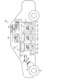
図1は、第1の実施形態に係る電極の一例を概略的に示す断面図である。図1に示す電極500は、集電体501と集電体501の上に配置される電極合剤層502とを備える。集電体501は、電極合剤層502により被覆されていない部分、すなわち、タブ501aを含む。電極合剤層502は、複数の活物質粒子502aを含む。電極合剤層502は多孔質である。
FIG. 1 is a cross-sectional view schematically showing an example of an electrode according to the first embodiment. The
図1に示す電極500は、集電体501と電極合剤層502との積層体を、有機分子溶液に浸漬した後乾燥させることにより得られたものである。集電体501の主面において、活物質粒子502aが接触していない部分は、第1自己組織化膜503cにより被覆されている。電極合剤層502の各々の主面は、第2自己組織化膜503bにより被覆されている。集電体のタブ501aの両方の主面は、第3自己組織化膜503aにより被覆されている。第1乃至第3自己組織化膜は、互いに同一の有機分子からなる。なお、第1乃至第3自己組織化膜は、互いに異なる有機分子を含んでいてもよい。
The
集電体501及び集電体のタブ501aの側面の少なくとも一部も、自己組織化膜により被覆されていてもよい。また、電極合剤層502の側面の少なくとも一部も、自己組織化膜により被覆されていてもよい。更に、電極合剤層502内の活物質粒子502aの表面上も、自己組織化膜により被覆されていてもよい。
At least a part of the side surface of the
第1乃至第3自己組織化膜は、同じ有機分子より形成されてもよく、それぞれ異なる有機分子でもよい。また、第1乃至第3自己組織化膜を自己組織化膜とも記載する。 The first to third self-assembled films may be formed from the same organic molecule, or may be different organic molecules. Further, the first to third self-assembled monolayers are also referred to as self-assembled monolayers.
(第2の実施形態)
第2の実施形態に係る二次電池は、正極と、負極と、水系電解質と、を備え、正極と負極の少なくとも一方は第1の実施形態に係る電極である。第2の実施形態に係る二次電池において用いることができる各部材の材料について詳しく説明する。
(Second embodiment)
The secondary battery according to the second embodiment includes a positive electrode, a negative electrode, and an aqueous electrolyte, and at least one of the positive electrode and the negative electrode is the electrode according to the first embodiment. The material of each member that can be used in the secondary battery according to the second embodiment will be described in detail.
1)負極
負極は、負極集電体と、負極集電体上に配置されている負極合剤層とを含む。負極合剤層は、負極集電体の少なくとも1つの面上に配置されている。例えば、負極集電体上の1つの面に負極合剤層が配置されていてもよく、または負極集電体上の1つの面とその裏面とに負極合剤層が配置されていてもよい。
1) Negative electrode The negative electrode includes a negative electrode current collector and a negative electrode mixture layer arranged on the negative electrode current collector. The negative electrode mixture layer is arranged on at least one surface of the negative electrode current collector. For example, the negative electrode mixture layer may be arranged on one surface on the negative electrode current collector, or the negative electrode mixture layer may be arranged on one surface on the negative electrode current collector and its back surface. ..
負極合剤層は、チタン酸化物、リチウムチタン酸化物、およびリチウムチタン複合酸化物からなる群より選択される少なくとも1種の化合物を含む負極活物質を含む。これら酸化物は1種類で用いることもできるし、複数種類を用いても良い。これらの酸化物では、リチウム電位基準にて1V以上2V以下(vs.Li/Li+)の範囲内でLi挿入脱離反応が起こる。そのため、二次電池の負極活物質としてこれらの酸化物を用いた場合には、充放電に伴う体積膨張収縮変化が小さいことから長寿命を実現することができる。 The negative electrode mixture layer contains a negative electrode active material containing at least one compound selected from the group consisting of titanium oxide, lithium titanium oxide, and lithium titanium composite oxide. These oxides may be used alone or in combination of two or more. With these oxides, the Li insertion / desorption reaction occurs within the range of 1 V or more and 2 V or less (vs. Li / Li + ) based on the lithium potential. Therefore, when these oxides are used as the negative electrode active material of the secondary battery, a long life can be realized because the change in volume expansion / contraction due to charging / discharging is small.
負極集電体には、Zn、Ga、In、Bi、Tl、Sn、Pb、Ti、Alから選ばれる少なくとも1種の元素Aを集電体内に含むことが好ましい。これらの元素は、これらの1種類で用いることもできるし、複数種類の元素を用いても良く、金属または金属合金として含むことができる。このような金属および金属合金は、単独で含まれていてもよく、或いは2種以上を混合して含んでいてもよい。これらの元素Aを集電体内に含んだ場合、集電体の機械的強度が高められ、加工性能が向上する。さらに、水系溶媒の電気分解を抑制し、水素発生を抑制させる効果が増加する。上記元素Aのなかでも、Zn、Pb、Ti、Alがより好ましい。 The negative electrode current collector preferably contains at least one element A selected from Zn, Ga, In, Bi, Tl, Sn, Pb, Ti, and Al in the current collector. These elements may be used in one of these elements, or a plurality of types of elements may be used, and may be contained as a metal or a metal alloy. Such metals and metal alloys may be contained alone or may be contained in combination of two or more. When these elements A are contained in the current collector, the mechanical strength of the current collector is enhanced and the processing performance is improved. Further, the effect of suppressing the electrolysis of the aqueous solvent and suppressing the generation of hydrogen is increased. Among the above elements A, Zn, Pb, Ti and Al are more preferable.
集電体は、例えばこれらの金属からなる金属箔である。また、集電体は、例えばこれらの金属を含んだ合金からなる箔である。このような箔は、元素A以外に例えば後述する元素を1種または2種以上含み得る。金属体の形状としては、箔以外にも、例えばメッシュや多孔体などが挙げられる。エネルギー密度や出力向上のためには、体積が小さく、表面積が大きい箔の形状が望ましい。 The current collector is, for example, a metal leaf made of these metals. Further, the current collector is, for example, a foil made of an alloy containing these metals. Such a foil may contain, for example, one or more elements described below in addition to the element A. Examples of the shape of the metal body include a mesh and a porous body in addition to the foil. In order to improve energy density and output, a foil shape with a small volume and a large surface area is desirable.
また、負極集電体は、元素Aとは異なる金属を含んだ基板を含むことができる。このような場合、この基板の表面の少なくとも一部に元素Aを含む化合物が存在することで、水素発生を抑制できる。表面に存在する元素Aを含む化合物は、負極合剤層と接するように配置されていることが望ましい。例えば基板に元素Aのメッキを施して、基板の表面に元素Aを存在させることができる。または、基板の表面に元素Aを含む合金を用いたメッキ処理を施すことができる。 Further, the negative electrode current collector can include a substrate containing a metal different from the element A. In such a case, hydrogen generation can be suppressed by the presence of the compound containing the element A on at least a part of the surface of the substrate. It is desirable that the compound containing the element A present on the surface is arranged so as to be in contact with the negative electrode mixture layer. For example, the substrate can be plated with the element A so that the element A can be present on the surface of the substrate. Alternatively, the surface of the substrate can be plated with an alloy containing the element A.
集電体は、元素Aからなる群より選択される少なくとも1種の化合物を含んでいてもよい。これら元素A酸化物、および/または元素A水酸化物、および/または塩基性炭酸元素A化合物、および/または元素Aの硫酸化合物は、集電体の表面領域の少なくとも一部において、表面から深さ方向へ5nm以上1μm以下までの深さ領域において含まれていることが好ましい。なお、元素Aの酸化物の例としてはZnO、元素Aの水酸化物の例としてはZn(OH)2、元素Aの塩基性炭酸化合物の例としては2ZnCO3・3Zn(OH)2、元素Aの硫酸化合物の例としては、ZnSO4・7H2Oなどが挙げられる。 The current collector may contain at least one compound selected from the group consisting of element A. These element A oxides and / or element A hydroxides and / or basic carbon dioxide element A compounds and / or element A sulfuric acid compounds are deep from the surface in at least a portion of the surface region of the current collector. It is preferably contained in a depth region of 5 nm or more and 1 μm or less in the isth direction. An example of an oxide of element A is ZnO, an example of a hydroxide of element A is Zn (OH) 2 , an example of a basic carbonate compound of element A is 2ZnCO 3.3 Zn (OH) 2 , and an element. Examples of the sulfuric acid compound of A include ZnSO 4.7H 2 O and the like.
集電体の表層部分に元素Aの酸化物、元素Aの水酸化物、元素Aの塩基性炭酸化合物、および元素Aの硫酸化合物の何れかが少なくとも1種存在すると、水素発生を抑制することができる。また、これらの化合物が集電体の表層部分に存在すると、集電体と活物質との密着性が向上し、電子伝導のパスを増やすことができることからサイクル特性の向上と、低抵抗化が可能である。 When at least one of an oxide of element A, a hydroxide of element A, a basic carbonic acid compound of element A, and a sulfuric acid compound of element A is present on the surface layer of the current collector, hydrogen generation is suppressed. Can be done. Further, when these compounds are present on the surface layer of the current collector, the adhesion between the current collector and the active material is improved, and the path of electron conduction can be increased, so that the cycle characteristics are improved and the resistance is lowered. It is possible.
基板は、Al、Fe、Cu、Ni、Tiから選択される少なくとも1種の金属を含むことが好ましい。これらの金属は、合金として含むこともできる。また、基板は、このような金属および金属合金を単独で含むことができ、或いは2種以上を混合して含むことができる。軽量化の観点から、基板がAl、Ti、またはこれらの合金を含むことが好ましい。 The substrate preferably contains at least one metal selected from Al, Fe, Cu, Ni and Ti. These metals can also be included as alloys. Further, the substrate may contain such a metal and a metal alloy alone, or may contain two or more kinds in a mixture. From the viewpoint of weight reduction, it is preferable that the substrate contains Al, Ti, or an alloy thereof.
集電体に元素Aからなる群より選択される少なくとも1種の化合物を含んでいるかどうかは、先述したように電池を分解し、その後、例えば誘導結合プラズマ(Inductively Coupled Plasma;ICP)発光分析を行うことで、調べることができる。 Whether or not the current collector contains at least one compound selected from the group consisting of element A is determined by decomposing the battery as described above and then performing, for example, inductively coupled plasma (ICP) emission analysis. By doing it, you can find out.
負極活物質は、チタン酸化物、リチウムチタン酸化物、およびリチウムチタン複合酸化物からなる群より選択される1種類又は2種類以上の化合物を含む。リチウムチタン複合酸化物の例に、ニオブチタン酸化物およびナトリウムニオブチタン酸化物が含まれる。これらの化合物のLi吸蔵電位は、1V(vs.Li/Li+)以上3V(vs.Li/Li+)以下の範囲であることが望ましい。 The negative electrode active material contains one or more compounds selected from the group consisting of titanium oxides, lithium titanium oxides, and lithium titanium composite oxides. Examples of lithium-titanium composite oxides include niobium-titanium oxide and sodium niobium-titanium oxide. The Li occlusion potential of these compounds is preferably in the range of 1 V (vs. Li / Li + ) or more and 3 V (vs. Li / Li + ) or less.
チタン酸化物の例に、単斜晶構造のチタン酸化物、ルチル構造のチタン酸化物、アナターゼ構造のチタン酸化物が含まれる。各結晶構造のチタン酸化物は、充電前の組成がTiO2、充電後の組成がLixTiO2(xは0≦x)で表すことができる。また、単斜晶構造のチタン酸化物の充電前構造をTiO2(B)と表すことができる。チタン酸化物は、酸化チタンとも称する。 Examples of titanium oxides include titanium oxide having a monoclinic structure, titanium oxide having a rutile structure, and titanium oxide having an anatase structure. The titanium oxide having each crystal structure can be represented by the composition before charging as TiO 2 and the composition after charging as Li x TiO 2 (x is 0 ≦ x). Further, the pre-charging structure of the titanium oxide having a monoclinic structure can be expressed as TiO 2 (B). Titanium oxide is also referred to as titanium oxide.
リチウムチタン酸化物の例に、スピネル構造リチウムチタン酸化物(例えば一般式Li4+xTi5O12(xは-1≦x≦3))、ラムスデライト構造のリチウムチタン酸化物(例えば、Li2+xTi3O7(-1≦x≦3))、Li1+xTi2O4(0≦x≦1)、Li1.1+xTi1.8O4(0≦x≦1)、Li1.07+xTi1.86O4(0≦x≦1)、LixTiO2(0<x)などが含まれる。 Examples of lithium titanium oxides include spinel-structured lithium titanium oxides (eg, general formula Li 4 + x Ti 5 O 12 (x is -1≤x≤3)) and rams delite-structured lithium titanium oxides (eg, Li 2 + x Ti). 3 O 7 (-1 ≤ x ≤ 3)), Li 1 + x Ti 2 O 4 (0 ≤ x ≤ 1), Li 1.1 + x Ti 1.8 O 4 (0 ≤ x ≤ 1), Li 1.07 + x Ti 1.86 O 4 (0 ≦ x ≦ 1), Li x TiO 2 (0 <x) and the like are included.
ニオブチタン酸化物の例に、LiaTiMbNb2±βO7±σ(0≦a≦5、0≦b≦0.3、0≦β≦0.3、0≦σ≦0.3、MはFe、V、Mo及びTaよりなる群から選択される少なくとも1種の元素)で表されるものが含まれる。ニオブチタン酸化物は、ニオブチタン複合酸化物とも称する。 Examples of niobium titanium oxides include Li a TiM b Nb 2 ± β O 7 ± σ (0 ≦ a ≦ 5, 0 ≦ b ≦ 0.3, 0 ≦ β ≦ 0.3, 0 ≦ σ ≦ 0.3, M includes those represented by at least one element selected from the group consisting of Fe, V, Mo and Ta). The niobium-titanium oxide is also referred to as a niobium-titanium composite oxide.
ナトリウムニオブチタン酸化物の例に、一般式Li2+vNa2-wM1xTi6-y-zNbyM2zO14+δ(0≦v≦4、0<w<2、0≦x<2、0<y<6、0≦z<3、y+z<6、-0.5≦δ≦0.5、M1はCs、K、Sr、Ba、Caより選択される少なくとも1つを含み、M2はZr、Sn、V、Ta、Mo、W、Fe、Co、Mn、Alより選択される少なくとも1つを含む)で表される斜方晶型Na含有ニオブチタン複合酸化物が含まれる。 An example of sodium niobium titanium oxide is the general formula Li 2 + v Na 2-w M1 x Ti 6-y-z Nby M2 z O 14 + δ (0 ≦ v ≦ 4, 0 <w <2, 0 ≦ x <2, 0 <y <6, 0 ≦ z <3, y + z <6, −0.5 ≦ δ ≦ 0.5, M1 contains at least one selected from Cs, K, Sr, Ba, Ca, and M2 is Includes an orthodox Na-containing niobium titanium composite oxide represented by (including at least one selected from Zr, Sn, V, Ta, Mo, W, Fe, Co, Mn, Al).
負極活物質として好ましい化合物に、アナターゼ構造のチタン酸化物、単斜晶構造のチタン酸化物、スピネル構造のリチウムチタン酸化物が含まれる。各化合物は、Li吸蔵電位が1.4V(vs.Li/Li+)以上2V(vs.Li/Li+)以下の範囲であるため、例えば正極活物質としてのリチウムマンガン酸化物と組み合わせることで、高い起電力を得ることができる。これらの中でも、スピネル構造のリチウムチタン酸化物は、充放電反応による体積変化が極めて少ないため、より好ましい。 Preferred compounds as the negative electrode active material include titanium oxide having an anatase structure, titanium oxide having a monoclinic structure, and lithium titanium oxide having a spinel structure. Since each compound has a Li storage potential in the range of 1.4 V (vs. Li / Li + ) or more and 2 V (vs. Li / Li + ) or less, for example, by combining it with lithium manganese oxide as a positive electrode active material. , High electromotive force can be obtained. Among these, lithium titanium oxide having a spinel structure is more preferable because the volume change due to the charge / discharge reaction is extremely small.
負極活物質は、粒子の形態で負極合剤層に含有され得る。負極活物質粒子は、単独の一次粒子、一次粒子の凝集体である二次粒子、あるいは、単独の一次粒子と二次粒子の混合物であり得る。粒子の形状は、特に限定されるものではなく、例えば、球状、楕円形状、扁平形状、繊維状等にすることができる。 The negative electrode active material may be contained in the negative electrode mixture layer in the form of particles. The negative electrode active material particles can be a single primary particle, a secondary particle which is an aggregate of the primary particles, or a mixture of a single primary particle and a secondary particle. The shape of the particles is not particularly limited, and may be, for example, spherical, elliptical, flat, fibrous, or the like.
負極活物質の二次粒子の平均粒子径(直径)が、3μm以上であることが好ましい。より好ましくは5μm以上20μm以下である。この範囲であると、活物質の表面積が小さいため、水素発生を抑制する効果を高めることができる。 The average particle diameter (diameter) of the secondary particles of the negative electrode active material is preferably 3 μm or more. More preferably, it is 5 μm or more and 20 μm or less. Within this range, the surface area of the active material is small, so that the effect of suppressing hydrogen generation can be enhanced.
二次粒子の平均粒子径が3μm以上の負極活物質は、例えば、次の方法で得られる。先ず、活物質原料を反応合成して平均粒子径1μm以下の活物質前駆体を作製する。その後、活物質前駆体に対し焼成処理を行い、ボールミルやジェトミルなどの粉砕機を用いて粉砕処理を施す。次いで焼成処理において、活物質前駆体を凝集して粒子径の大きい二次粒子に成長させる。 A negative electrode active material having an average particle diameter of secondary particles of 3 μm or more can be obtained, for example, by the following method. First, an active material raw material is reacted and synthesized to prepare an active material precursor having an average particle diameter of 1 μm or less. After that, the active material precursor is fired and then crushed using a crusher such as a ball mill or a jet mill. Next, in the firing process, the active material precursor is aggregated and grown into secondary particles having a large particle size.
負極活物質の一次粒子の平均粒子径は1μm以下とすることが望ましい。これにより、活物質内部でのLiイオンの拡散距離が短くなり、比表面積が大きくなる。そのため、優れた高入力性能(急速充電性能)が得られる。一方、平均粒子径が小さいと、粒子の凝集が起こりやすくなり、電解質の分布が負極に偏って正極での電解質の枯渇を招く恐れがあることから、下限値は0.001μmにすることが望ましい。さらに好ましい平均粒子径は、0.1μm以上0.8μm以下である。 It is desirable that the average particle size of the primary particles of the negative electrode active material is 1 μm or less. As a result, the diffusion distance of Li ions inside the active material is shortened, and the specific surface area is increased. Therefore, excellent high input performance (quick charge performance) can be obtained. On the other hand, if the average particle size is small, agglomeration of particles is likely to occur, and the distribution of the electrolyte is biased toward the negative electrode, which may lead to the depletion of the electrolyte at the positive electrode. Therefore, it is desirable to set the lower limit to 0.001 μm. .. A more preferable average particle size is 0.1 μm or more and 0.8 μm or less.
負極活物質粒子は、N2析出によるBET法での比表面積が3m2/g以上200m2/g以下の範囲であることが望ましい。これにより、負極と電解質との親和性をさらに高くすることができる。 It is desirable that the specific surface area of the negative electrode active material particles by the BET method by N2 precipitation is in the range of 3 m 2 / g or more and 200 m 2 / g or less. This makes it possible to further increase the affinity between the negative electrode and the electrolyte.
負極合剤層(集電体を除く)の比表面積は、3m2/g以上50m2/g以下の範囲であることが望ましい。比表面積のより好ましい範囲は、5m2/g以上50m2/g以下である。負極合剤層は、集電体上に担持された負極活物質、導電剤及び結着剤を含む多孔質の層であり得る。 The specific surface area of the negative electrode mixture layer (excluding the current collector) is preferably in the range of 3 m 2 / g or more and 50 m 2 / g or less. A more preferable range of the specific surface area is 5 m 2 / g or more and 50 m 2 / g or less. The negative electrode mixture layer can be a porous layer containing a negative electrode active material, a conductive agent and a binder supported on the current collector.
負極の多孔度(集電体を除く)は、20~50%の範囲にすることが望ましい。これにより、負極と電解質との親和性に優れ、かつ高密度な負極を得ることができる。多孔度のさらに好ましい範囲は、25~40%である。 The porosity of the negative electrode (excluding the current collector) is preferably in the range of 20 to 50%. As a result, it is possible to obtain a negative electrode having excellent affinity between the negative electrode and the electrolyte and having a high density. A more preferred range of porosity is 25-40%.
導電剤としては、アセチレンブラック、カーボンブラック、コークス、炭素繊維、黒鉛などの炭素材料やニッケル、亜鉛などの金属粉末を挙げることができる。導電剤の種類は1種類または2種類以上にすることができる。炭素材料は、それ自身から水素が発生するため、導電剤には金属粉末を使用することが望ましい。 Examples of the conductive agent include carbon materials such as acetylene black, carbon black, coke, carbon fiber and graphite, and metal powders such as nickel and zinc. The type of the conductive agent can be one type or two or more types. Since hydrogen is generated from the carbon material itself, it is desirable to use a metal powder as the conductive agent.
結着剤としては、例えば、ポリテトラフルオロエチレン(PTFE)、ポリフッ化ビニリデン(PVdF)、フッ素系ゴム、エチレン-ブタジエンゴム、ポリプロピレン(PP)、ポリエチレン(PE)、カルボキシメチルセルロース(CMC)、ポリイミド(PI)、ポリアクリルイミド(PAI)などが挙げられる。結着剤の種類は1種類または2種類以上にすることができる。 Examples of the binder include polytetrafluoroethylene (PTFE), polyvinylidene fluoride (PVdF), fluorine-based rubber, ethylene-butadiene rubber, polypropylene (PP), polyethylene (PE), carboxymethyl cellulose (CMC), and polyimide ( PI), polyacrylicimide (PAI) and the like can be mentioned. The type of binder may be one type or two or more types.
負極活物質、導電剤及び結着剤の負極合剤層における配合比については、負極活物質は70重量%以上95重量%以下、導電剤は3重量%以上20重量%以下、結着剤は2重量%以上10重量%以下の範囲にすることが好ましい。導電剤の配合比が3重量%以上であれば負極の導電性を良好にすることができ、20重量%以下であれば導電剤表面での電解質の分解を低減することができる。結着剤の配合比が2重量%以上であれば十分な電極強度が得られ、10重量%以下であれば電極の絶縁部を減少させることが出来る。 Regarding the compounding ratio of the negative electrode active material, the conductive agent and the binder in the negative electrode mixture layer, the negative electrode active material is 70% by weight or more and 95% by weight or less, the conductive agent is 3% by weight or more and 20% by weight or less, and the binder is. It is preferably in the range of 2% by weight or more and 10% by weight or less. When the compounding ratio of the conductive agent is 3% by weight or more, the conductivity of the negative electrode can be improved, and when it is 20% by weight or less, the decomposition of the electrolyte on the surface of the conductive agent can be reduced. When the compounding ratio of the binder is 2% by weight or more, sufficient electrode strength can be obtained, and when it is 10% by weight or less, the insulating portion of the electrode can be reduced.
負極は、例えば次のようにして作製することができる。先ず、負極活物質、導電剤及び結着剤を適切な溶媒に分散させてスラリーを調製する。このスラリーを集電体に塗布し、塗膜を乾燥させることで集電体上に負極合剤層を形成する。ここで、例えばスラリーを集電体上の1つの面に塗布してもよく、またはスラリーを集電体上の1つの面とその裏面とに塗布してもよい。次いで、集電体と負極合剤層とに対し、例えば加熱プレスなどのプレスを施すことにより負極を作製することができる。 The negative electrode can be manufactured, for example, as follows. First, the negative electrode active material, the conductive agent and the binder are dispersed in an appropriate solvent to prepare a slurry. This slurry is applied to the current collector and the coating film is dried to form a negative electrode mixture layer on the current collector. Here, for example, the slurry may be applied to one surface on the current collector, or the slurry may be applied to one surface on the current collector and its back surface. Next, the negative electrode can be manufactured by applying a press such as a heating press to the current collector and the negative electrode mixture layer.
2)正極
この正極は、正極集電体と、正極集電体の片面もしくは両面に担持され、活物質、導電剤および結着剤を含む正極合剤層とを有することができる。
2) Positive electrode This positive electrode can have a positive electrode current collector and a positive electrode mixture layer supported on one or both sides of the positive electrode current collector and containing an active material, a conductive agent and a binder.
正極集電体としてはステンレス、Al、Tiなどの金属からなる箔、多孔体、メッシュを用いることが好ましい。集電体と電解質との反応による集電体の腐食を防止するため、集電体表面を異種元素で被覆してもよい。 As the positive electrode current collector, it is preferable to use a foil, a porous body, or a mesh made of a metal such as stainless steel, Al, or Ti. In order to prevent corrosion of the current collector due to the reaction between the current collector and the electrolyte, the surface of the current collector may be coated with a different element.
正極活物質には、リチウムやナトリウムを吸蔵放出可能なものが使用され得る。正極は、1種類の正極活物質を含んでも良く、或いは2種類以上の正極活物質を含むことができる。正極活物質の例には、リチウムマンガン複合酸化物、リチウムニッケル複合酸化物、リチウムコバルトアルミニウム複合酸化物、リチウムニッケルコバルトマンガン複合酸化物、スピネル型リチウムマンガンニッケル複合酸化物、リチウムマンガンコバルト複合酸化物、リチウム鉄酸化物、リチウムフッ素化硫酸鉄、オリビン結晶構造のリン酸化合物(例えば、LixFePO4(0≦x≦1)、LixMnPO4(0≦x≦1))などが含まれる。オリビン結晶構造のリン酸化合物は、熱安定性に優れている。 As the positive electrode active material, a substance capable of occluding and releasing lithium or sodium can be used. The positive electrode may contain one kind of positive electrode active material, or may contain two or more kinds of positive electrode active materials. Examples of positive electrode active materials include lithium manganese composite oxide, lithium nickel composite oxide, lithium cobalt aluminum composite oxide, lithium nickel cobalt manganese composite oxide, spinel type lithium manganese nickel composite oxide, and lithium manganese cobalt composite oxide. , Lithium iron oxide, lithium fluorinated iron sulfate, phosphoric acid compounds having an olivine crystal structure (for example, Li x FePO 4 (0 ≦ x ≦ 1), Li x MnPO 4 (0 ≦ x ≦ 1)) and the like. .. The phosphoric acid compound having an olivine crystal structure has excellent thermal stability.
高い正極電位の得られる正極活物質の例を以下に記載する。例えばスピネル構造のLixMn2O4(0<x≦1)、LixMnO2(0<x≦1)などのリチウムマンガン複合酸化物、例えばLixNi1-yAlyO2(0<x≦1、0<y≦1)などのリチウムニッケルアルミニウム複合酸化物、例えばLixCoO2(0<x≦1)などのリチウムコバルト複合酸化物、例えばLixNi1-y-zCoyMnzO2(0<x≦1、0<y≦1、0≦z≦1)などのリチウムニッケルコバルト複合酸化物、例えばLixMnyCo1-yO2(0<x≦1、0<y≦1)などのリチウムマンガンコバルト複合酸化物、例えばLixMn2-yNiyO4(0<x≦1、0<y<2)などのスピネル型リチウムマンガンニッケル複合酸化物、例えばLixFePO4(0<x≦1)、LixFe1-yMnyPO4(0<x≦1、0≦y≦1)、LixCoPO4(0<x≦1)などのオリビン構造を有するリチウムリン酸化物、フッ素化硫酸鉄(例えばLixFeSO4F(0<x≦1))が挙げられる。 Examples of positive electrode active materials that can obtain a high positive electrode potential are described below. For example, lithium manganese composite oxides such as Li x Mn 2 O 4 (0 <x ≦ 1) and Li x MnO 2 (0 <x ≦ 1) having a spinel structure, for example, Li x Ni 1-y Ally O 2 (0). Lithium-nickel-aluminum composite oxides such as <x ≦ 1, 0 <y ≦ 1), such as lithium cobalt composite oxides such as Li x CoO 2 (0 <x ≦ 1), such as Li x Ni 1-yz Co. Lithium-nickel-cobalt composite oxides such as y Mn z O 2 (0 <x ≦ 1, 0 <y ≦ 1, 0 ≦ z ≦ 1), such as Li x Mn y Co 1-y O 2 (0 <x ≦ 1). , 0 <y ≦ 1) and other lithium manganese cobalt composite oxides, such as spinnel type lithium manganese nickel composite oxides such as Li x Mn 2-y Ny O 4 (0 <x ≦ 1, 0 <y <2). For example, Li x FePO 4 (0 <x ≦ 1), Li x Fe 1-y Mn y PO 4 (0 <x ≦ 1, 0 ≦ y ≦ 1), Li x CoPO 4 (0 <x ≦ 1), etc. Examples thereof include a lithium phosphorus oxide having an olivine structure and iron fluorinated iron sulfate (for example, Li x FeSO 4 F (0 <x ≦ 1)).
また、ナトリウムマンガン複合酸化物、ナトリウムニッケル複合酸化物、ナトリムコバルト複合酸化物、ナトリムニッケルコバルトマンガン複合酸化物、ナトリウム鉄複合酸化物、ナトリウムリン酸化物(例えば、ナトリウムリン酸鉄、ナトリウムリン酸バナジウム)、ナトリウム鉄マンガン複合酸化物、ナトリウムニッケルチタン複合酸化物、ナトリウムニッケル鉄複合酸化物、ナトリウムニッケルマンガン複合酸化物などが含まれる。 In addition, sodium manganese composite oxide, sodium nickel composite oxide, Natrim cobalt composite oxide, Natrim nickel cobalt manganese composite oxide, sodium iron composite oxide, sodium phosphate oxide (for example, iron sodium phosphate, vanadium sodium phosphate). ), Sodium iron manganese composite oxide, sodium nickel titanium composite oxide, sodium nickel iron composite oxide, sodium nickel manganese composite oxide and the like.
好ましい正極活物質の例に、鉄複合酸化物(例えばNayFeO2、0≦y≦1)、鉄マンガン複合酸化物(例えばNayFe1-xMnxO2、0<x<1、0≦y≦1)、ニッケルチタン複合酸化物(例えばNayNi1-xTixO2、0<x<1、0≦y≦1)、ニッケル鉄複合酸化物(例えばNayNi1-xFexO2、0<x<1、0≦y≦1)、ニッケルマンガン複合酸化物(例えばNayNi1-xMnxO2、0<x<1、0≦y≦1)、ニッケルマンガン鉄複合酸化物(例えばNayNi1-x-zMnxFezO2、0<x<1、0≦y≦1、0<z<1、0<1-x-z<1)、リン酸鉄(例えばNayFePO4、0≦y≦1)が含まれる。 Examples of preferred positive electrode active materials include iron composite oxides (eg, Ny FeO 2 , 0 ≦ y ≦ 1), iron manganese composite oxides (eg, Ny Fe 1-x Mn x O 2 , 0 <x <1, 0 ≦ y ≦ 1), nickel-titanium composite oxide (for example, Na y Ni 1-x Ti x O 2 , 0 <x <1, 0 ≦ y ≦ 1), nickel iron composite oxide (for example, Na y Ni 1- ). x Fe x O 2 , 0 <x <1, 0 ≦ y ≦ 1), nickel-manganese composite oxide (eg, Ny Ni 1-x Mn x O 2 , 0 <x <1, 0 ≦ y ≦ 1), Nickel manganese iron composite oxide (for example, Ny Ni 1-x-z Mn x Fe z O 2 , 0 <x <1, 0 ≦ y ≦ 1, 0 <z <1, 0 <1-x-z <1 ), Iron phosphate (eg, Nay FePO 4 , 0 ≦ y ≦ 1).
正極活物質の粒子は、単独の一次粒子、一次粒子の凝集体である二次粒子、または単独の一次粒子と二次粒子の双方を含むものであり得る。正極活物質の一次粒子の平均粒子径(直径)は10μm以下であることが好ましく、より好ましくは0.1μm~5μmである。正極活物質の二次粒子の平均粒子径(直径)は100μm以下であることが好ましく、より好ましくは10μm~50μmである。 The particles of the positive electrode active material can be single primary particles, secondary particles that are aggregates of primary particles, or both single primary particles and secondary particles. The average particle diameter (diameter) of the primary particles of the positive electrode active material is preferably 10 μm or less, more preferably 0.1 μm to 5 μm. The average particle diameter (diameter) of the secondary particles of the positive electrode active material is preferably 100 μm or less, and more preferably 10 μm to 50 μm.
正極活物質の粒子表面の少なくとも一部が炭素材料で被覆されていることが好ましい。炭素材料は、層構造、粒子構造、あるいは粒子の集合体の形態をとり得る。 It is preferable that at least a part of the particle surface of the positive electrode active material is covered with a carbon material. The carbon material can be in the form of a layered structure, a particle structure, or an aggregate of particles.
正極合剤層の電子伝導性を高め、集電体との接触抵抗を抑えるための導電剤としては、例えば、アセチレンブラック、カーボンブラック、黒鉛、平均繊維径1μm以下の炭素繊維等を挙げることができる。導電剤の種類は1種類又は2種類以上にすることができる。 Examples of the conductive agent for increasing the electron conductivity of the positive electrode mixture layer and suppressing the contact resistance with the current collector include acetylene black, carbon black, graphite, and carbon fibers having an average fiber diameter of 1 μm or less. can. The type of the conductive agent may be one type or two or more types.
活物質と導電剤とを結着させるための結着剤は、例えば、ポリテトラフルオロエチレン(PTFE)、ポリフッ化ビニリデン(PVdF)、フッ素系ゴム、エチレン-ブタジエンゴム(SBR)、ポリプロピレン(PP)、ポリエチレン(PE)、カルボキシメチルセルロース(CMC)、ポリイミド(PI)、ポリアクリルイミド(PAI)を含む。結着剤の種類は1種類又は2種類以上にすることができる。 The binder for binding the active material and the conductive agent is, for example, polytetrafluoroethylene (PTFE), polyvinylidene fluoride (PVdF), fluorine-based rubber, ethylene-butadiene rubber (SBR), polypropylene (PP). , Polyethylene (PE), Carboxymethylcellulose (CMC), Polyimide (PI), Polyacrylicimide (PAI). The type of binder may be one type or two or more types.
正極活物質、導電剤及び結着剤の正極合剤層における配合比については、正極活物質は70重量%以上95重量%以下、導電剤は3重量%以上20重量%以下、結着剤は2重量%以上10重量%以下の範囲にすることが好ましい。導電剤の配合比が3重量%以上であれば正極の導電性を良好にすることができ、20重量%以下であれば導電剤表面での電解質の分解を低減することができる。結着剤の配合比が2重量%以上であれば十分な電極強度が得られ、10重量%以下であれば電極の絶縁部を減少させることが出来る。 Regarding the compounding ratio of the positive electrode active material, the conductive agent and the binder in the positive electrode mixture layer, the positive electrode active material is 70% by weight or more and 95% by weight or less, the conductive agent is 3% by weight or more and 20% by weight or less, and the binder is. It is preferably in the range of 2% by weight or more and 10% by weight or less. When the compounding ratio of the conductive agent is 3% by weight or more, the conductivity of the positive electrode can be improved, and when it is 20% by weight or less, the decomposition of the electrolyte on the surface of the conductive agent can be reduced. When the compounding ratio of the binder is 2% by weight or more, sufficient electrode strength can be obtained, and when it is 10% by weight or less, the insulating portion of the electrode can be reduced.
正極は、例えば次のようにして作製することができる。先ず、正極活物質、導電剤及び結着剤を適切な溶媒に分散させてスラリーを調製する。このスラリーを集電体に塗布し、塗膜を乾燥させることで集電体上に正極合剤層を形成する。ここで、例えばスラリーを集電体上の1つの面に塗布してもよく、またはスラリーを集電体上の1つの面とその裏面とに塗布してもよい。次いで、集電体と正極合剤層とに対し、例えば加熱プレスなどのプレスを施すことにより正極を作製することができる。
3)電解質
電解質には、水系溶媒と第1の電解質とを含む電解液と、この電解液に高分子材料を複合化したゲル状電解質が挙げられる。この電解質を水系電解質ともいう。前述の高分子材料としては、例えば、ポリフッ化ビニリデン(PVdF)、ポリアクリロニトリル(PAN)、ポリエチレンオキサイド(PEO)等を挙げることができる。ここでは、電解液について説明する。電解質は、NO3
-、Cl-、LiSO4
-、SO4
2-、およびOH-からなる群より選択される少なくとも1種のアニオンを含む。電解質中に含まれるこれらのアニオンは、1種でもよく、或いは、2種以上のアニオンが含まれていてもよい。なお、電解液とゲル状電解質を総称するために用いた電解質と、溶質としての電解質を区別するために便宜上溶質としての電解質を第1の電解質と称している。
The positive electrode can be produced, for example, as follows. First, a positive electrode active material, a conductive agent and a binder are dispersed in an appropriate solvent to prepare a slurry. This slurry is applied to the current collector and the coating film is dried to form a positive electrode mixture layer on the current collector. Here, for example, the slurry may be applied to one surface on the current collector, or the slurry may be applied to one surface on the current collector and its back surface. Next, the positive electrode can be produced by applying a press such as a heating press to the current collector and the positive electrode mixture layer.
3) Electrolyte Examples of the electrolyte include an electrolytic solution containing an aqueous solvent and a first electrolyte, and a gel-like electrolyte in which a polymer material is compounded with the electrolytic solution. This electrolyte is also called an aqueous electrolyte. Examples of the above-mentioned polymer material include polyvinylidene fluoride (PVdF), polyacrylonitrile (PAN), polyethylene oxide (PEO) and the like. Here, the electrolytic solution will be described. The electrolyte contains at least one anion selected from the group consisting of NO 3- , Cl- , LiSO 4-, SO 4 2- , and OH-. These anions contained in the electrolyte may be one kind or may contain two or more kinds of anions. The electrolyte as a solute is referred to as a first electrolyte for convenience in order to distinguish between the electrolyte used to collectively refer to the electrolytic solution and the gel-like electrolyte and the electrolyte as the solute.
水系溶媒としては、水を含む溶液を用いることができる。ここで、水を含む溶液とは、純水であってもよく、或いは水と水以外の物質との混合溶液や混合溶媒であってもよい。 As the aqueous solvent, a solution containing water can be used. Here, the solution containing water may be pure water, or may be a mixed solution of water and a substance other than water, or a mixed solvent.
上記電解質は、溶質となる塩1molに対し、水溶媒量(例えば水系溶媒中の水量)が1mol以上であることが好ましい。さらに好ましい形態は、溶質となる塩1molに対する水溶媒量が3.5mol以上である。 The amount of the aqueous solvent (for example, the amount of water in the aqueous solvent) is preferably 1 mol or more with respect to 1 mol of the salt as the solute. A more preferable form is that the amount of the aqueous solvent with respect to 1 mol of the salt as a solute is 3.5 mol or more.
第1の電解質としては、水系溶媒に溶解したときに解離して上記アニオンを生じさせるものを用いることができる。特に、Liイオンと上記アニオンとに解離するリチウム塩が好ましい。このようなリチウム塩としては、例えばLiNO3、LiCl、Li2SO4、LiOHなどを挙げることができる。 As the first electrolyte, one that dissociates when dissolved in an aqueous solvent to generate the above-mentioned anion can be used. In particular, a lithium salt that dissociates between the Li ion and the anion is preferable. Examples of such lithium salts include LiNO 3 , LiCl, Li 2 SO 4 , LiOH and the like.
また、Liイオンと上記アニオンへと解離するリチウム塩は、水系溶媒における溶解度が比較的高い。そのため、アニオンの濃度が1-10Mと高く、Liイオン拡散性が良好である電解質を得ることができる。 Further, the lithium salt that dissociates from the Li ion and the above anion has a relatively high solubility in an aqueous solvent. Therefore, an electrolyte having a high anion concentration of 1-10M and good Li ion diffusivity can be obtained.
NO3 -及び/又はCl-を含む電解質は、0.1-10M程度の幅広いアニオン濃度の範囲で用いることができる。イオン伝導度と、リチウム平衡電位の両立の観点から、これらのアニオンの濃度が3-12Mと高いことが好ましい。NO3 -またはCl-を含む電解質のアニオン濃度が8-12Mであることがより好ましい。 The electrolyte containing NO 3- and / or Cl - can be used in a wide range of anion concentrations of about 0.1-10M. From the viewpoint of achieving both ionic conductivity and lithium equilibrium potential, the concentration of these anions is preferably as high as 3-12M. It is more preferable that the anion concentration of the electrolyte containing NO 3- or Cl- is 8-12M.
LiSO4 -及び/又はSO4 2-を含む電解質は、0.05-2.5M程度のアニオン濃度の範囲で用いることができる。イオン伝導度の観点から、これらのアニオンの濃度が1.5-2.5Mと高いことが好ましい。 The electrolyte containing LiSO 4- and / or SO 4-2- can be used in the range of anion concentration of about 0.05-2.5 M. From the viewpoint of ionic conductivity, the concentration of these anions is preferably as high as 1.5-2.5M.
電解質中のOH-濃度は、10-10-0.1Mであることが望ましい。 The OH-concentration in the electrolyte is preferably 10-10-0.1M .
また、電解質はリチウムイオンとナトリウムイオンとの両方を含むことができる。 Also, the electrolyte can contain both lithium and sodium ions.
電解質中の溶質、即ち第1の電解質は、例えばイオンクロマトグラフ法により定性および定量することができる。イオンクロマトグラフ法は、感度が高いため、分析手法として特に好ましい。 The solute in the electrolyte, i.e., the first electrolyte, can be qualitatively and quantified, for example, by ion chromatography. The ion chromatograph method is particularly preferable as an analytical method because of its high sensitivity.
イオンクロマトグラフ法による電解質に含まれる溶質の定性定量分析の具体的な測定条件の例を以下に示す:
システム: Prominence HIC-SP
分析カラム: Shim-pack IC-SA3
ガードカラム: Shim-pack IC-SA3(G)
溶離液: 3.6 mmol/L 炭酸ナトリウム水溶液
流量: 0.8 mL/min
カラム温度: 45℃
注入量: 50μL
検出: 電気伝導度
電解質中に水が含まれているかは、ガスクロマトグラフィー質量分析(Gas Chromatography - Mass Spectrometry;GC-MS)測定により確認できる。また、電解質中の水含有量の算出は、例えばICPの発光分析などで測定することができる。また電解質の比重を測定することで、溶媒のモル数を算出できる。電解質は正極側と負極側で同じものを用いてもよいし、異なるものを用いてもよい。この場合、正極の電解質のpHは1以上7以下であることが好ましい。正極の電解質のpHが8以上となると水の電気分解に起因する酸素発生反応が有利に進み、pH1未満だと活物質の分解が進行するため、好ましくない。負極の電解質はpH7以上であることが好ましく7未満では水の電気分解に起因する水素発生反応が有利に進むため、好ましくない。
Examples of specific measurement conditions for qualitative quantitative analysis of solutes contained in electrolytes by ion chromatography are shown below:
System: Prominence HIC-SP
Analytical column: Shim-pack IC-SA3
Guard column: Shim-pack IC-SA3 (G)
Eluent: 3.6 mmol / L sodium carbonate aqueous solution Flow rate: 0.8 mL / min
Column temperature: 45 ° C
Injection volume: 50 μL
Detection: Electrical Conductivity Whether water is contained in the electrolyte can be confirmed by gas chromatography-mass spectrometry (GC-MS) measurement. Further, the calculation of the water content in the electrolyte can be measured by, for example, luminescence analysis of ICP. In addition, the number of moles of the solvent can be calculated by measuring the specific gravity of the electrolyte. The same electrolyte may be used on the positive electrode side and the negative electrode side, or different electrolytes may be used. In this case, the pH of the electrolyte of the positive electrode is preferably 1 or more and 7 or less. When the pH of the electrolyte of the positive electrode is 8 or more, the oxygen evolution reaction caused by the electrolysis of water proceeds advantageously, and when the pH is less than 1, the decomposition of the active substance proceeds, which is not preferable. The pH of the electrolyte of the negative electrode is preferably 7 or more, and if it is less than 7, the hydrogen generation reaction caused by the electrolysis of water proceeds advantageously, which is not preferable.
また、電解質には第1の実施形態で説明した有機分子を含んでいてもよい。 Further, the electrolyte may contain the organic molecule described in the first embodiment.
4)セパレータ
正極と負極との間にはセパレータを配置することができる。セパレータを絶縁材料で構成することで、正極と負極とが電気的に接触することを防止することができる。また、正極と負極との間を電解質が移動可能な形状のものを使用することが望ましい。セパレータの例に、不織布、フィルム、紙などが含まれる。セパレータの構成材料の例に、ポリエチレンやポリプロピレンなどのポリオレフィン、セルロースが含まれる。好ましいセパレータの例に、セルロース繊維を含む不織布、ポリオレフィン繊維を含む多孔質フィルムを挙げることができる。セパレータの気孔率は60%以上にすることが好ましい。また、繊維径は10μm以下が好ましい。繊維径を10μm以下にすることで、電解質に対するセパレータの親和性が向上するので電池抵抗を小さくすることができる。繊維径のより好ましい範囲は3μm以下である。気孔率が60%以上のセルロース繊維含有不織布は、電解質の含浸性が良く、低温から高温まで高い出力性能を出すことができる。また、長期充電保存、フロート充電、過充電においても負極と反応せず、リチウム金属のデンドライト析出による負極と正極の短絡が発生しない。より好ましい範囲は62%~80%である。
4) Separator A separator can be placed between the positive electrode and the negative electrode. By forming the separator with an insulating material, it is possible to prevent the positive electrode and the negative electrode from electrically contacting each other. Further, it is desirable to use a shape in which the electrolyte can move between the positive electrode and the negative electrode. Examples of separators include non-woven fabrics, films, paper and the like. Examples of the constituent materials of the separator include polyolefins such as polyethylene and polypropylene, and cellulose. Examples of preferred separators include non-woven fabrics containing cellulose fibers and porous films containing polyolefin fibers. The porosity of the separator is preferably 60% or more. The fiber diameter is preferably 10 μm or less. By setting the fiber diameter to 10 μm or less, the affinity of the separator with respect to the electrolyte is improved, so that the battery resistance can be reduced. A more preferable range of the fiber diameter is 3 μm or less. A cellulose fiber-containing non-woven fabric having a porosity of 60% or more has good impregnation property of an electrolyte and can exhibit high output performance from low temperature to high temperature. In addition, it does not react with the negative electrode even during long-term charge storage, float charging, and overcharging, and a short circuit between the negative electrode and the positive electrode does not occur due to dendrite precipitation of lithium metal. A more preferable range is 62% to 80%.
また、セパレータとして、固体電解質を使用することもできる。固体電解質としてはNASICON型骨格を有するLATP(Li1+xAlxTi2-x(PO4)3;0.1≦x≦0.4)、アモルファス状のLIPON(Li2.9PO3.3N0.46)、ガーネット型のLLZ(Li7La3Zr2O12)などの酸化物が好ましい。 Further, a solid electrolyte can also be used as the separator. As the solid electrolyte, LATP (Li 1 + x Al x Ti 2-x (PO 4 ) 3 ; 0.1 ≦ x ≦ 0.4) having a NASICON type skeleton and amorphous LIPON (Li 2.9 PO 3.3 N) 0.46 ), garnet-type LLZ (Li 7 La 3 Zr 2 O 12 ) and other oxides are preferred.
また、βアルミナ、Na1+xZr2SixP3-xO12(0≦x≦3)、NaAlSi3O8などもあげることができる。 Further, β-alumina, Na 1 + x Zr 2 Si x P 3-x O 12 (0 ≦ x ≦ 3), NaAlSi 3 O 8 and the like can also be mentioned.
セパレータは、厚さが20μm以上100μm以下、密度が0.2g/cm3以上0.9g/cm3以下であることが好ましい。この範囲であると、機械的強度と電池抵抗の軽減のバランスを取ることができ、高出力で内部短絡が抑制された二次電池を提供することができる。また、高温環境下でのセパレータの熱収縮が少なく、良好な高温貯蔵性能を出すことが出来る。 The separator preferably has a thickness of 20 μm or more and 100 μm or less and a density of 0.2 g / cm 3 or more and 0.9 g / cm 3 or less. Within this range, a balance between mechanical strength and reduction of battery resistance can be achieved, and a secondary battery having high output and suppressed internal short circuit can be provided. In addition, the separator has little heat shrinkage in a high temperature environment, and good high temperature storage performance can be obtained.
5)容器
正極、負極及び電解質が収容される容器には、金属製容器や、ラミネートフィルム製容器、ポリエチレンやポリプロピレンなどの樹脂容器を使用することができる。
5) Container As the container in which the positive electrode, the negative electrode and the electrolyte are housed, a metal container, a laminated film container, or a resin container such as polyethylene or polypropylene can be used.
金属製容器としては、ニッケル、鉄、ステンレス、亜鉛などからなる金属缶で角形、円筒形の形状のものが使用できる。 As the metal container, a metal can made of nickel, iron, stainless steel, zinc or the like and having a square or cylindrical shape can be used.
樹脂製容器、金属製容器それぞれの板厚は、1mm以下にすることが望ましく、さらに好ましい範囲は0.5mm以下である。さらに好ましい範囲は0.3mm以下である。また、板厚の下限値は、0.05mmにすることが望ましい。 The plate thickness of each of the resin container and the metal container is preferably 1 mm or less, and a more preferable range is 0.5 mm or less. A more preferable range is 0.3 mm or less. Further, it is desirable that the lower limit of the plate thickness is 0.05 mm.
ラミネートフィルムとしては、例えば、金属層を樹脂層で被覆した多層フィルムなどを挙げることができる。金属層の例に、ステンレス箔、アルミニウム箔、アルミニウム合金箔が含まれる。樹脂層には、ポリプロピレン(PP)、ポリエチレン(PE)、ナイロン、ポリエチレンテレフタレート(PET)などの高分子を用いることができる。ラミネートフィルムの厚さの好ましい範囲は、0.5mm以下である。より好ましい範囲は0.2mm以下である。また、ラミネートフィルムの厚さの下限値は、0.01mmにすることが望ましい。 Examples of the laminated film include a multilayer film in which a metal layer is coated with a resin layer. Examples of metal layers include stainless steel foils, aluminum foils, aluminum alloy foils. As the resin layer, a polymer such as polypropylene (PP), polyethylene (PE), nylon, or polyethylene terephthalate (PET) can be used. The preferable range of the thickness of the laminated film is 0.5 mm or less. A more preferable range is 0.2 mm or less. Further, it is desirable that the lower limit of the thickness of the laminated film is 0.01 mm.
実施形態に係る二次電池は、角形、円筒形、扁平型、薄型、コイン型等の様々な形態の二次電池に適用することが可能である。さらにバイポーラ構造を有する二次電池であることが好ましい。これにより複数直列のセルを1個のセルで作製できる利点がある。 The secondary battery according to the embodiment can be applied to various types of secondary batteries such as a square type, a cylindrical type, a flat type, a thin type, and a coin type. Further, it is preferable that the secondary battery has a bipolar structure. This has the advantage that a plurality of serial cells can be produced with one cell.
実施形態に係る二次電池の一例を図2~図5を参照して説明する。 An example of the secondary battery according to the embodiment will be described with reference to FIGS. 2 to 5.
図2及び図3に、金属製容器を用いた二次電池の一例を示す。 2 and 3 show an example of a secondary battery using a metal container.
電極群1は、矩形筒状の金属製容器2内に収納されている。電極群1は、正極3及び負極4をその間にセパレータ5を介在させて偏平形状となるように渦巻き状に .回した構造を有する。電解質(図示しない)は、電極群1に保持されている。図3に示すように、電極群1の端面に位置する正極3の端部の複数個所それぞれに帯状の正極リード6が電気的に接続されている。また、この端面に位置する負極4の端部の複数個所それぞれに帯状の負極リード7が電気的に接続されている。この複数ある正極リード6は、一つに束ねられた状態で正極導電タブ8と電気的に接続されている。正極リード6と正極導電タブ8から正極端子が構成されている。また、負極リード7は、一つに束ねられた状態で負極導電タブ9と接続されている。負極リード7と負極導電タブ9から負極端子が構成されている。金属製の封口板10は、金属製容器2の開口部に溶接等により固定されている。正極導電タブ8及び負極導電タブ9は、それぞれ、封口板10に設けられた取出穴から外部に引き出されている。封口板10の各取出穴の内周面は、正極導電タブ8及び負極導電タブ9との接触による短絡を回避するために、絶縁部材で被覆されている。
The
封口板10の各取出穴の内周面には、正極タブ8及び負極タブ9との接触による短絡を回避するために、それぞれ正極ガスケット18及び負極ガスケット19が配置されている。正極ガスケット18及び負極ガスケット19を配置することで、角型二次電池の気密性を維持できる。
A
封口板10には制御弁22(安全弁)が配置されている。水系溶媒の電気分解により発生したガスに起因して電池セルにおける内圧が高まった場合には、制御弁22から発生ガスを外部へと放散できる。制御弁22としては、例えば内圧が設定値よりも高くなった場合に作動し、内圧が低下すると封止栓として機能する復帰式のものを使用することができる。或いは、一度作動すると封止栓としての機能が回復しない非復帰式の制御弁を使用してもよい。図2では、制御弁22が封口板10の中央に配置されているが、制御弁22の位置は封口板10の端部であってもよい。制御弁22は省略してもよい。
A control valve 22 (safety valve) is arranged on the sealing
また、封口板10には注液口23が設けられている。電解質は、この注液口23を介して注液され得る。注液口23は、電解質が注液された後、封止栓24により塞がれている。注液口23及び封止栓24は省略してもよい。
Further, the sealing
図4及び図5に、ラミネートフィルム製外装部材を用いた二次電池の一例を示す。 4 and 5 show an example of a secondary battery using a laminated film exterior member.
積層型電極群1は、2枚の樹脂フィルムの間に金属層を介在したラミネートフィルムからなる袋状容器2内に収納されている。積層型電極群1は、図5に示すように正極3と負極4とをその間にセパレータ5を介在させながら交互に積層した構造を有する。正極3は複数枚存在し、それぞれが集電体3aと、集電体3aの両面に形成された正極合剤層3bとを備える。負極4は複数枚存在し、それぞれが集電体4aと、集電体4aの両面に形成された負極合剤層4bとを備える。各負極4の集電体4aは、一辺が正極3から突出している。突出した集電体4aは、帯状の負極端子12に電気的に接続されている。帯状の負極端子12の先端は、容器2から外部に引き出されている。また、図示しないが、正極3の集電体3aは、集電体4aの突出辺と反対側に位置する辺が負極4から突出している。負極4から突出した集電体3aは、帯状の正極端子13に電気的に接続されている。帯状の正極端子13の先端は、負極端子12とは反対側に位置し、容器2の辺から外部に引き出されている。
The
図2~図5に示す二次電池には、容器内に発生した水素ガスを外部に放出させるための安全弁を設けることができる。安全弁は、内圧が設定値よりも高くなった場合に作動し、内圧が低下すると封止栓として機能する復帰式、一度作動すると封止栓としての機能が回復しない非復帰式のいずれでも使用可能である。また、図2~図5に示す二次電池は、密閉式であるが、水素ガスを水に戻す循環システムを備える場合には開放系とすることが可能である。 The secondary batteries shown in FIGS. 2 to 5 may be provided with a safety valve for releasing the hydrogen gas generated in the container to the outside. The safety valve can be used with either a return type that operates when the internal pressure rises above the set value and functions as a sealing plug when the internal pressure drops, or a non-returning type that does not recover the function as a sealing plug once it operates. Is. Further, although the secondary batteries shown in FIGS. 2 to 5 are closed type, they can be an open system when provided with a circulation system for returning hydrogen gas to water.
以上説明した実施形態によれば、第1の実施形態に係る電極を備えることができる二次電池であることにより、電解質の水電気分解や電極の腐食といった副反応抑制をすることができ、電池特性である自己放電の抑制や、充放電効率の向上、寿命を向上させることができる。 According to the embodiment described above, since the secondary battery can be provided with the electrode according to the first embodiment, it is possible to suppress side reactions such as water electrolysis of the electrolyte and corrosion of the electrode, and the battery It is possible to suppress self-discharge, which is a characteristic, improve charge / discharge efficiency, and improve the life.
(第3の実施形態)
第3の実施形態によれば、二次電池を単位セルとする組電池を提供することができる。二次電池には、第2の実施形態の二次電池を用いることができる。
(Third embodiment)
According to the third embodiment, it is possible to provide an assembled battery having a secondary battery as a unit cell. As the secondary battery, the secondary battery of the second embodiment can be used.
組電池の例には、電気的に直列又は並列に接続された複数の単位セルを構成単位として含むもの、電気的に直列接続された複数の単位セルからなるユニットまたは電気的に並列接続された複数の単位セルからなるユニットを含むもの等を挙げることができる。 Examples of assembled batteries include a plurality of unit cells electrically connected in series or in parallel as a constituent unit, a unit consisting of a plurality of electrically connected unit cells connected in series, or electrically connected in parallel. Examples include those including a unit composed of a plurality of unit cells.
組電池は、筐体に収容されていても良い。筐体は、アルミニウム合金、鉄、ステンレスなどからなる金属缶、プラスチック容器等が使用できる。また、容器の板厚は、0.5mm以上にすることが望ましい。 The assembled battery may be housed in a housing. As the housing, a metal can made of aluminum alloy, iron, stainless steel, etc., a plastic container, or the like can be used. Further, it is desirable that the plate thickness of the container is 0.5 mm or more.
二次電池の複数個を電気的に直列又は並列接続する形態の例には、それぞれが容器を備えた複数の二次電池を電気的に直列又は並列接続するもの、共通の筐体内に収容された複数の電極群を電気的に直列又は並列接続するものが含まれる。前者の具体例は、複数個の二次電池の正極端子と負極端子を金属製のバスバー(例えば、アルミニウム、ニッケル、銅)で接続するものである。後者の具体例は、1個の筐体内に複数個の電極群を隔壁により電気化学的に絶縁した状態で収容し、これら電極群を電気的に直列接続するものである。電気的に直列接続する電池個数を5~7の範囲にすることにより、鉛蓄電池との電圧互換性が良好になる。鉛蓄電池との電圧互換性をより高くするには、単位セルを5個または6個直列接続した構成が好ましい。 Examples of the form in which a plurality of secondary batteries are electrically connected in series or in parallel include those in which a plurality of secondary batteries each having a container are electrically connected in series or in parallel, and are housed in a common housing. This includes those in which a plurality of electrodes are electrically connected in series or in parallel. A specific example of the former is to connect the positive electrode terminal and the negative electrode terminal of a plurality of secondary batteries with a metal bus bar (for example, aluminum, nickel, copper). A specific example of the latter is to accommodate a plurality of electrode groups in a single housing in a state where they are electrochemically insulated by a partition wall, and these electrode groups are electrically connected in series. By setting the number of batteries electrically connected in series in the range of 5 to 7, the voltage compatibility with the lead storage battery is improved. In order to improve the voltage compatibility with the lead storage battery, a configuration in which 5 or 6 unit cells are connected in series is preferable.
組電池の一例を図6を参照して説明する。図6に示す組電池31は、第2の実施形態に係る角型の二次電池(例えば図2、図3)321~325を単位セルとして複数備える。電池321の正極導電タブ8と、その隣に位置する電池322の負極導電タブ9とが、リード33によって電気的に接続されている。さらに、この電池322の正極導電タブ8とその隣に位置する電池323の負極導電タブ9とが、リード33によって電気的に接続されている。このように電池321~325間が直列に接続されている。
An example of the assembled battery will be described with reference to FIG. The assembled
第3の実施形態の組電池によれば、第2の実施形態に係る二次電池含んでいるため、自己放電の抑制や、充放電効率の向上、寿命を向上させることができる組電池を提供することができる。 According to the assembled battery of the third embodiment, since the secondary battery according to the second embodiment is included, the assembled battery capable of suppressing self-discharge, improving the charge / discharge efficiency, and improving the life is provided. can do.
(第4の実施形態)
第4の実施形態によれば、電池パックが提供される。この電池パックは、第2の実施形態に係る二次電池を具備している。
(Fourth Embodiment)
According to the fourth embodiment, a battery pack is provided. This battery pack comprises the secondary battery according to the second embodiment.
第4の実施形態に係る電池パックは、先に説明した第2の実施形態に係る二次電池(単位セル)を1個または複数個具備することができる。第4の実施形態に係る電池パックに含まれ得る複数の二次電池は、電気的に直列、並列、又は直列および並列を組み合わせて接続されることができる。また、複数の二次電池は、電気的に接続された組電池を構成することもできる。複数の二次電池から組電池を構成する場合、第3の実施形態の組電池を使用することができる。 The battery pack according to the fourth embodiment may include one or a plurality of secondary batteries (unit cells) according to the second embodiment described above. The plurality of secondary batteries that may be included in the battery pack according to the fourth embodiment can be electrically connected in series, in parallel, or in combination of series and parallel. Further, the plurality of secondary batteries can also form an electrically connected assembled battery. When the assembled battery is composed of a plurality of secondary batteries, the assembled battery of the third embodiment can be used.
第4の実施形態に係る電池パックは、保護回路をさらに具備することができる。保護回路は、二次電池の充放電を制御するものである。或いは、電池パックを電源として使用する装置(例えば、電子機器、自動車等)に含まれる回路を、電池パックの保護回路として使用することができる。 The battery pack according to the fourth embodiment may further include a protection circuit. The protection circuit controls the charging and discharging of the secondary battery. Alternatively, a circuit included in a device that uses the battery pack as a power source (for example, an electronic device, an automobile, etc.) can be used as a protection circuit of the battery pack.
また、第4の実施形態に係る電池パックは、通電用の外部端子をさらに具備することもできる。通電用の外部端子は、二次電池からの電流を外部に出力するため、及び/又は単位セル51に電流を入力するためのものである。言い換えれば、電池パックを電源として使用する際、電流が通電用の外部端子を通して外部に供給される。また、電池パックを充電する際、充電電流(自動車などの動力の回生エネルギーを含む)は通電用の外部端子59を通して電池パックに供給される。
Further, the battery pack according to the fourth embodiment may further include an external terminal for energization. The external terminal for energization is for outputting the current from the secondary battery to the outside and / or for inputting the current to the
第4の実施形態に係る電池パックの例を、図7を参照して説明する。図7は、電池パックの一例を示す模式的な斜視図である。 An example of the battery pack according to the fourth embodiment will be described with reference to FIG. 7. FIG. 7 is a schematic perspective view showing an example of a battery pack.
電池パック40は、図4、7に示す二次電池からなる組電池を備える。電池パック40は、筐体41と、筐体41内に収容された組電池42とを含む。組電池42は、複数(例えば5個)の二次電池431~435が電気的に直列に接続されたものである。二次電池431~435は、厚さ方向に積層されている。筐体41は、上部及び4つの側面それぞれに開口部44を有している。二次電池431~435の正負極端子12、13が突出している側面が、筐体41の開口部44に露出している。組電池42の出力用正極端子45は、帯状をなし、一端が二次電池431~435のいずれかの正極端子13と電気的に接続され、かつ他端が筐体41の開口部44から突出して筐体41の上部から突き出ている。一方、組電池42の出力用負極端子46は、帯状をなし、一端が二次電池431~435のいずれかの負極端子12と電気的に接続され、かつ他端が筐体41の開口部44から突出して筐体41の上部から突き出ている。
The
第4の実施形態に係る電池パックの別の例を図8および図9を参照して詳細に説明する。図8は、第4の実施形態に係る他の例の電池パックの分解斜視図である。図9は、図8の電池パックの電気回路を示すブロック図である。 Another example of the battery pack according to the fourth embodiment will be described in detail with reference to FIGS. 8 and 9. FIG. 8 is an exploded perspective view of a battery pack of another example according to the fourth embodiment. FIG. 9 is a block diagram showing an electric circuit of the battery pack of FIG.
扁平型の二次電池から構成される複数の単位セル51は、外部に延出した負極端子52および正極端子53が同じ向きに揃えられるように積層され、粘着テープ54で締結することにより組電池55を構成している。これらの単位セル51は、図9に示すように互いに電気的に直列に接続されている。
A plurality of
プリント配線基板56は、負極端子52および正極端子53が延出する単位セル51側面と対向して配置されている。プリント配線基板56には、図9に示すようにサーミスタ57、保護回路58及び通電用の外部端子59が搭載されている。なお、組電池55と対向するプリント配線基板56の面には組電池55の配線と不要な接続を回避するために絶縁板(図示せず)が取り付けられている。
The printed
正極リード60は、組電池55の最下層に位置する正極端子53に接続され、その先端はプリント配線基板56の正極コネクタ61に挿入されて電気的に接続されている。負極リード62は、組電池55の最上層に位置する負極端子52に接続され、その先端はプリント配線基板56の負極側コネクタ63に挿入されて電気的に接続されている。これらのコネクタ61、63は、プリント配線基板56に形成された配線64、65を通して保護回路58に接続されている。
The
サーミスタ57は、単位セル51の温度を検出し、その検出信号は保護回路58に送信される。保護回路58は、所定の条件で保護回路58と通電用の外部端子59との間のプラス配線66aおよびマイナス配線66bを遮断できる。所定の条件とは、例えばサーミスタ57の検出温度が所定温度以上になったときである。また、所定の条件とは単位セル51の過充電、過放電、過電流等を検出したときである。この過充電等の検出は、個々の単位セル51もしくは組電池55について行われる。個々の単位セル51を検出する場合、電池電圧を検出してもよいし、正極電位もしくは負極電位を検出してもよい。後者の場合、個々の単位セル51中に参照極として用いるリチウム電極が挿入される。図8および図9の場合、単位セル51それぞれに電圧検出のための配線67を接続し、これら配線67を通して検出信号が保護回路58に送信される。
The
正極端子53および負極端子52が突出する側面を除く組電池55の三側面には、ゴムもしくは樹脂からなる保護シート68がそれぞれ配置されている。
A
組電池55は、各保護シート68およびプリント配線基板56と共に収納容器69内に収納される。すなわち、収納容器69の長辺方向の両方の内側面と短辺方向の内側面それぞれに保護シート68が配置され、短辺方向の反対側の内側面にプリント配線基板56が配置される。組電池55は、保護シート68およびプリント配線基板56で囲まれた空間内に位置する。蓋70は、収納容器69の上面に取り付けられている。
The assembled
なお、組電池55の固定には粘着テープ54に代えて、熱収縮テープを用いてもよい。この場合、組電池の両側面に保護シートを配置し、熱収縮テープを周回させた後、熱収縮テープを熱収縮させて組電池を結束させる。
A heat-shrinkable tape may be used instead of the
図8、図9では単位セル51を直列接続した形態を示したが、電池容量を増大させるためには並列に接続してもよい。或いは、直列接続と並列接続とを組み合わせてもよい。さらに、組み上がった電池パックを直列および/または並列に接続することもできる。
Although FIGS. 8 and 9 show a form in which the
また、電池パックの態様は用途により適宜変更される。電池パックの用途としては、大電流での充放電が望まれるものが好ましい。具体的には、デジタルカメラの電源用や、二輪乃至四輪のハイブリッド電気自動車、二輪乃至四輪の電気自動車、アシスト自転車、鉄道用車両等の車両の車載用、並びに定置用電池としての用途が挙げられる。特に、車載用が好適である。 In addition, the mode of the battery pack is appropriately changed depending on the application. The battery pack is preferably used for charging and discharging with a large current. Specifically, it is used as a power source for digital cameras, in-vehicle vehicles such as two-wheeled to four-wheeled hybrid electric vehicles, two-wheeled to four-wheeled electric vehicles, assisted bicycles, and railway vehicles, and as stationary batteries. Can be mentioned. In particular, it is suitable for in-vehicle use.
第4の実施形態に係る電池パックを搭載した自動車等の車両において、電池パックは、例えば車両の動力の回生エネルギーを回収するものである。 In a vehicle such as an automobile equipped with the battery pack according to the fourth embodiment, the battery pack recovers, for example, the regenerative energy of the power of the vehicle.
以上説明した第4の実施形態の電池パックによれば、第2の実施形態の二次電池を含むため、自己放電の抑制や、充放電効率の向上、寿命を向上させることができる電池パックを提供することができる。 According to the battery pack of the fourth embodiment described above, since the secondary battery of the second embodiment is included, the battery pack capable of suppressing self-discharge, improving the charge / discharge efficiency, and improving the life is provided. Can be provided.
(第5の実施形態)
第5の実施形態によると、車両が提供される。この車両は、第4の実施形態に係る電池パックを搭載している。
(Fifth Embodiment)
According to the fifth embodiment, a vehicle is provided. This vehicle is equipped with the battery pack according to the fourth embodiment.
第5の実施形態に係る車両において、電池パックは、例えば、車両の動力の回生エネルギーを回収するものである。 In the vehicle according to the fifth embodiment, the battery pack recovers, for example, the regenerative energy of the power of the vehicle.
第5の実施形態に係る車両の例としては、例えば、二輪乃至四輪のハイブリッド電気自動車、二輪乃至四輪の電気自動車、アシスト自転車、及び鉄道用車両が挙げられる。 Examples of the vehicle according to the fifth embodiment include, for example, a two-wheel to four-wheel hybrid electric vehicle, a two-wheel to four-wheel electric vehicle, an assisted bicycle, and a railroad vehicle.
第5の実施形態に係る車両における電池パックの搭載位置は、特には限定されない。例えば、電池パックを自動車に搭載する場合、電池パックは、車両のエンジンルーム、車体後方又は座席の下に搭載することができる。 The mounting position of the battery pack in the vehicle according to the fifth embodiment is not particularly limited. For example, when the battery pack is mounted in an automobile, the battery pack can be mounted in the engine room of the vehicle, behind the vehicle body, or under the seat.
次に、第5の実施形態に係る車両の一例について、図面を参照しながら説明する。 Next, an example of the vehicle according to the fifth embodiment will be described with reference to the drawings.
図10は、第5の実施形態に係る車両の一例を概略的に示す断面図である。 FIG. 10 is a cross-sectional view schematically showing an example of the vehicle according to the fifth embodiment.
図10に示す車両71は、車両本体と、電池パック72とを含んでいる。電池パック72は、第4の実施形態に係る電池パックであり得る。
The
図10に示す車両71は、四輪の自動車である。車両71としては、例えば、二輪乃至四輪のハイブリッド電気自動車、二輪乃至四輪の電気自動車、アシスト自転車、及び鉄道用車両を用いることができる。
The
この車両71は、複数の電池パック72を搭載してもよい。この場合、電池パック72は、直列に接続されてもよく、並列に接続されてもよく、直列接続及び並列接続を組み合わせて接続されてもよい。
The
電池パック72は、車両本体の前方に位置するエンジンルーム内に搭載されている。電池パック72の搭載位置は、特に限定されない。電池パック72は、車両本体の後方又は座席の下に搭載してもよい。この電池パック72は、車両71の電源として用いることができる。また、この電池パック72は、車両71の動力の回生エネルギーを回収することができる。
The
次に、図11を参照しながら、第5の実施形態に係る車両の実施態様について説明する。 Next, an embodiment of the vehicle according to the fifth embodiment will be described with reference to FIG. 11.
図11は、第5の実施形態に係る車両の他の例を概略的に示した図である。図11に示す車両300は、電気自動車である。
FIG. 11 is a diagram schematically showing another example of the vehicle according to the fifth embodiment. The
図11に示す車両300は、車両本体301と、車両用電源302と、車両用電源302の上位制御手段である車両ECU(ECU:Electric Control Unit;電気制御装置)380と、外部端子(外部電源に接続するための端子)370と、インバータ340と、駆動モータ345とを備えている。
The
車両300は、車両用電源302を、例えばエンジンルーム、自動車の車体後方又は座席の下に搭載している。なお、図11に示す、車両300では、車両用電源302の搭載箇所については概略的に示している。
The
車両用電源302は、複数(例えば3つ)の電池パック312a、312b及び312cと、電池管理装置(BMU:Battery Management Unit)311と、通信バス310と、を備えている。
The
3つの電池パック312a、312b及び312cは、電気的に直列に接続されている。電池パック312aは、組電池314aと組電池監視装置(VTM:Voltage Temperature Monitoring)313aと、を備えている。電池パック312bは、組電池314bと組電池監視装置313bと、を備えている。電池パック312cは、組電池314cと組電池監視装置313cと、を備えている。電池パック312a、312b、及び312cは、それぞれ独立して取り外すことが可能であり、別の電池パック312と交換することができる。
The three
組電池314a~314cのそれぞれは、直列に接続された複数の単電池を備えている。複数の単電池の少なくとも1つは、第2の実施形態に係る二次電池である。組電池314a~314cは、それぞれ、正極端子316及び負極端子317を通じて充放電を行う。
Each of the assembled
電池管理装置311は、車両用電源302の保全に関する情報を集めるために、組電池監視装置313a~313cとの間で通信を行い、車両用電源302に含まれる組電池314a~314cに含まれる単電池の電圧、及び温度などに関する情報を収集する。
The
電池管理装置311と組電池監視装置313a~313cとの間には、通信バス310が接続されている。通信バス310は、1組の通信線を複数のノード(電池管理装置と1つ以上の組電池監視装置と)で共有するように構成されている。通信バス310は、例えばCAN(Control Area Network)規格に基づいて構成された通信バスである。
A
組電池監視装置313a~313cは、電池管理装置311からの通信による指令に基づいて、組電池314a~314cを構成する個々の単電池の電圧及び温度を計測する。ただし、温度は1つの組電池につき数箇所だけで測定することができ、全ての単電池の温度を測定しなくてもよい。
The assembled
車両用電源302は、正極端子316と負極端子317との接続を入り切りするための電磁接触器(例えば図11に示すスイッチ装置333)を有することもできる。スイッチ装置333は、組電池314a~314cへの充電が行われるときにオンするプリチャージスイッチ(図示せず)、及び電池出力が負荷へ供給されるときにオンするメインスイッチ(図示せず)を含んでいる。プリチャージスイッチおよびメインスイッチは、スイッチ素子の近傍に配置されたコイルに供給される信号によりオン又はオフされるリレー回路(図示せず)を備えている。
The
インバータ340は、入力された直流電圧を、モータ駆動用の3相の交流(AC)の高電圧に変換する。インバータ340の3相の出力端子は、駆動モータ345の各3相の入力端子に接続されている。インバータ340は、電池管理装置311あるいは車両全体動作を制御するための車両ECU380からの制御信号に基づいて、出力電圧を制御する。
The
駆動モータ345は、インバータ340から供給される電力により回転する。この回転は、例えば差動ギアユニットを介して車軸および駆動輪Wに伝達される。
The
また、図示はしていないが、車両300は、回生ブレーキ機構(regenerator)を備えている。回生ブレーキ機構は、車両300を制動した際に駆動モータ345を回転させ、運動エネルギーを電気エネルギーとしての回生エネルギーに変換する。回生ブレーキ機構で回収した回生エネルギーは、インバータ340に入力され、直流電流に変換される。直流電流は、車両用電源302に入力される。
Further, although not shown, the
車両用電源302の負極端子317には、接続ラインL1の一方の端子が、電池管理装置311内の電流検出部(図示せず)を介して接続されている。接続ラインL1の他方の端子は、インバータ340の負極入力端子に接続されている。
One terminal of the connection line L1 is connected to the
車両用電源302の正極端子316には、接続ラインL2の一方の端子が、スイッチ装置333を介して接続されている。接続ラインL2の他方の端子は、インバータ340の正極入力端子に接続されている。
One terminal of the connection line L2 is connected to the
外部端子370は、電池管理装置311に接続されている。外部端子370は、例えば、外部電源に接続することができる。
The
車両ECU380は、運転者などの操作入力に応答して他の装置とともに電池管理装置311を協調制御して、車両全体の管理を行なう。電池管理装置311と車両ECU380との間では、通信線により、車両用電源302の残容量など、車両用電源302の保全に関するデータ転送が行われる。
The
第5の実施形態に係る車両は、第4の実施形態に係る電池パックを具備している。即ち、充放電効率と寿命性能の高い電池パックを備えているため、第5の実施形態に係る車両は充放電効率と寿命性能に優れており、且つ電池パックが自己放電特性に優れているため、信頼性が高い車両を提供することができる。 The vehicle according to the fifth embodiment is equipped with the battery pack according to the fourth embodiment. That is, since the battery pack has high charge / discharge efficiency and life performance, the vehicle according to the fifth embodiment has excellent charge / discharge efficiency and life performance, and the battery pack has excellent self-discharge characteristics. , It is possible to provide a highly reliable vehicle.
(第6の実施形態)
第6の実施形態によると、定置用電源が提供される。この定置用電源は、第4の実施形態に係る電池パックを搭載している。なお、この定置用電源は、第4の実施形態に係る電池パックの代わりに、第3の実施形態に係る組電池又は第2の実施形態に係る二次電池を搭載していてもよい。
(Sixth Embodiment)
According to the sixth embodiment, a stationary power supply is provided. This stationary power supply is equipped with the battery pack according to the fourth embodiment. The stationary power supply may be equipped with the assembled battery according to the third embodiment or the secondary battery according to the second embodiment instead of the battery pack according to the fourth embodiment.
第6の実施形態に係る定置用電源は、第4の実施形態に係る電池パックを搭載している。したがって、第6の実施形態に係る定置用電源は、長寿命を実現することができる。 The stationary power supply according to the sixth embodiment is equipped with the battery pack according to the fourth embodiment. Therefore, the stationary power supply according to the sixth embodiment can realize a long life.
図12は、第6実施形態に係る定置用電源を含むシステムの一例を示すブロック図である。図12は、第4の実施形態に係る電池パック40A、40Bの使用例として、定置用電源112、123への適用例を示す図である。図12に示す一例では、定置用電源112,123が用いられるシステム110が示される。システム110は、発電所111、定置用電源112、需要家側電力系統113及びエネルギー管理システム(EMS)115を備える。また、システム110には、電力網116及び通信網117が形成され、発電所111、定置用電源112、需要家側電力系統113及びEMS115は、電力網116及び通信網117を介して、接続される。EMS115は、電力網116及び通信網117を活用して、システム110全体を安定化させる制御を行う。
FIG. 12 is a block diagram showing an example of a system including a stationary power supply according to a sixth embodiment. FIG. 12 is a diagram showing an application example to the
発電所111は、火力及び原子力等の燃料源によって、大容量の電力を生成する。発電所111からは、電力網116等を通して電力が供給される。また、定置用電源112には、電池パック40Aが搭載される。電池パック40Aは、発電所111から供給される電力等を蓄電できる。また、定置用電源112は、電池パック40Aに蓄電された電力を、電力網116等を通して供給できる。システム110には、電力変換装置118が設けられる。電力変換装置118は、コンバータ、インバータ及び変圧器等を含む。したがって、電力変換装置118は、直流と交流との間の変換、互いに対して周波数が異なる交流の間の変換、及び、変圧(昇圧及び降圧)等を行うことができる。このため、電力変換装置118は、発電所111からの電力を、電池パック40Aへ蓄電可能な電力に変換できる。
The
需要家側電力系統113には、工場用の電力系統、ビル用の電力系統、及び、家庭用の電力系統等が、含まれる。需要家側電力系統113は、需要家側EMS121、電力変換装置122及び定置用電源123を備える。定置用電源123には、電池パック40Bが搭載される。需要家側EMS121は、需要家側電力系統113を安定化させる制御を行う。
The consumer-
需要家側電力系統113には、発電所111からの電力、及び、電池パック40Aからの電力が、電力網116を通して供給される。電池パック40Bは、需要家側電力系統113に供給された電力を蓄電できる。また、電力変換装置121は、電力変換装置118と同様に、コンバータ、インバータ及び変圧器等を含む。したがって、電力変換装置121は、直流と交流との間の変換、互いに対して周波数が異なる交流の間の変換、及び、変圧(昇圧及び降圧)等を行うことができる。このため、電力変換装置121は、需要家側電力系統113に供給された電力を、電池パック40Bへ蓄電可能な電力に変換できる。
The electric power from the
なお、電池パック40Bに蓄電された電力は、例えば、電気自動車等の車両の充電等に用いることができる。また、システム110には、自然エネルギー源が設けられてもよい。この場合、自然エネルギー源は、風力及び太陽光等の自然エネルギーによって、電力を生成する。そして、発電所111に加えて自然エネルギー源からも、電力網116を通して、電力が供給される。
The electric power stored in the
以下に実施例を説明するが、実施形態は、以下に掲載される実施例に限定されるものではない。
[実施例]
(正極の作製)
正極活物質として、100重量部のLiMn2O4の粉末を用い、導電剤として、10重量部のアセチレンブラックを用いた。また、結着剤として、10重量部のポリフッ化ビニリデン(PVdF)を用いた。そして、正極活物質、導電剤及び結着剤を、N-メチルピロリドン(N-methyl pyrrolidone;NMP)に加えて混合し、スラリーを調製した。また、調製したスラリーを、正極集電体の両面に塗布した。正極集電体は、厚さ15μmのチタン箔を用いた。そして、スラリーの塗膜を乾燥させた後、正極集電体と塗膜とに電極密度を2.5g/cm3となるようにプレスを施すことにより正極シートを作製した。作製した正極シートを打抜き、20mm×40mmのタブ部分と、40mm×40mmの電極部分と、から成る形状の正極を得た。
(負極の作製)
負極活物質として、100重量部のLi4Ti5O12粉末を用い、導電剤として、10重量部のアセチレンブラックを用いた。また、結着剤として、10重量部のPTFEを用いた。そして、負極活物質、導電剤及び結着剤を、NMPに加えて混合し、スラリーを調製した。また、調整したスラリーを、負極集電体の両面に塗布した。負極集電体は、層厚1μmの炭素含有被覆層を有する亜鉛箔を用い、厚さ15μmのものを用いた。そして、スラリーの塗膜を乾燥させた後、負極集電体と塗膜とに電極密度を2.0g/cm3になるようプレスを施すことにより負極シートを作製した。負極シートは、作製した負極シートを打抜き、20mm×40mmのタブ部分と、40mm×40mmの電極部分と、からなる形状の負極を形成した。
(負極への被覆層の形成)
打ち抜いた負極を2mMの1H,1H,2H,2H-パーフルオロ-n-へキシルホスホン酸(FHPA)水溶液に浸漬し、120℃にて加熱乾燥させて、被覆層を得た。被覆層の厚さをエリプソメーター(J.A. Woollam Co. Inc., Typ M44)により測定したところ、2.5nmであった。また、電極合剤層をエタノールにより剥離させて集電箔を露出させた後、集電箔を純水にて超音波洗浄し、集電箔表面に形成させた被覆層の厚さを測定した。その結果、集電箔表面の被覆層の厚さは0.5nmであった。
(二次電池の作製)
前述のように作製した正極及び負極を交互に積層して、電極群としてスタック体を作製した。スタック体では、正極と負極との間にセパレータを介在させ、セパレータによって、正極及び負極が互いに対して直接接触することを防止した。また、セパレータには、硬質ろ紙を用い、正極及び負極の電解質等の液体を介しての短絡を防止した。また、正極及び負極のそれぞれでは、タブ部分に対して、端子を超音波溶接した。端子は、表面を陽極酸化処理したアルミ二ウム製の端子を用いた。さらに、スタック体(電極群)を、ラミネートフィルムから成るパックに収納した。この際、ガラスフィルターでスタック体を挟み込み、スタック体(電極群)に電解質を含浸させ易くした。ガラスフィルターは、電極と同一形状で、厚さ1mmのフィルターを用いた。ラミネートフィルムとしては、厚さが40μmのアルミニウム箔の両面にポリプロピレン層が形成されたフィルムを、用いた。また、ラミネートフィルムの厚さは、0.1mmとした。
Examples will be described below, but the embodiments are not limited to the examples described below.
[Example]
(Preparation of positive electrode)
As the positive electrode active material, 100 parts by weight of LiMn 2 O 4 powder was used, and as the conductive agent, 10 parts by weight of acetylene black was used. In addition, 10 parts by weight of polyvinylidene fluoride (PVdF) was used as a binder. Then, the positive electrode active material, the conductive agent and the binder were added to N-methyl pyrrolidone (NMP) and mixed to prepare a slurry. Moreover, the prepared slurry was applied to both sides of the positive electrode current collector. A titanium foil having a thickness of 15 μm was used as the positive electrode current collector. Then, after the coating film of the slurry was dried, a positive electrode sheet was produced by pressing the positive electrode current collector and the coating film so that the electrode density was 2.5 g / cm 3 . The prepared positive electrode sheet was punched out to obtain a positive electrode having a shape consisting of a tab portion having a size of 20 mm × 40 mm and an electrode portion having a size of 40 mm × 40 mm.
(Manufacturing of negative electrode)
As the negative electrode active material, 100 parts by weight of Li 4 Ti 5 O 12 powder was used, and as the conductive agent, 10 parts by weight of acetylene black was used. Moreover, 10 parts by weight of PTFE was used as a binder. Then, the negative electrode active material, the conductive agent and the binder were added to NMP and mixed to prepare a slurry. Further, the adjusted slurry was applied to both sides of the negative electrode current collector. As the negative electrode current collector, a zinc foil having a carbon-containing coating layer having a layer thickness of 1 μm was used, and a current collector having a thickness of 15 μm was used. Then, after the coating film of the slurry was dried, a negative electrode sheet was produced by pressing the negative electrode current collector and the coating film so that the electrode density was 2.0 g / cm 3 . As the negative electrode sheet, the prepared negative electrode sheet was punched out to form a negative electrode having a shape consisting of a tab portion having a size of 20 mm × 40 mm and an electrode portion having a size of 40 mm × 40 mm.
(Formation of a coating layer on the negative electrode)
The punched negative electrode was immersed in a 2 mM 1H, 1H, 2H, 2H-perfluoro-n-hexylphosphonic acid (FHPA) aqueous solution and dried by heating at 120 ° C. to obtain a coating layer. The thickness of the coating layer was measured by an ellipsometer (JA Woollam Co. Inc., Typ M44) and found to be 2.5 nm. Further, after the electrode mixture layer was peeled off with ethanol to expose the current collector foil, the current collector foil was ultrasonically cleaned with pure water, and the thickness of the coating layer formed on the surface of the current collector foil was measured. .. As a result, the thickness of the coating layer on the surface of the current collector foil was 0.5 nm.
(Making a secondary battery)
The positive electrodes and negative electrodes prepared as described above were alternately laminated to prepare a stack as an electrode group. In the stack body, a separator was interposed between the positive electrode and the negative electrode, and the separator prevented the positive electrode and the negative electrode from coming into direct contact with each other. In addition, a hard filter paper was used as the separator to prevent short circuits through liquids such as electrolytes for the positive and negative electrodes. Further, in each of the positive electrode and the negative electrode, the terminals were ultrasonically welded to the tab portion. As the terminal, a terminal made of aluminum whose surface was anodized was used. Further, the stack body (electrode group) was housed in a pack made of a laminated film. At this time, the stack body was sandwiched between glass filters to facilitate impregnation of the stack body (electrode group) with the electrolyte. As the glass filter, a filter having the same shape as the electrode and having a thickness of 1 mm was used. As the laminated film, a film having polypropylene layers formed on both sides of an aluminum foil having a thickness of 40 μm was used. The thickness of the laminated film was 0.1 mm.
そして、作製した電極群に電解質として12MのLiCl水溶液を10ml滴下した。そして、電解質を注液した後、ラミネートフィルムのパックを、ヒートシールにより完全密閉した。これにより、ラミネートセル型の水系リチウムイオン電池を作製した。
(評価)
[被覆層の厚さ]
被覆層の厚さは、例えばエリプソメーター(J.A. Woollam Co. Inc., Typ M44)により測定した。電池から電極を取り出し、純水中に30分浸漬させた後、80℃真空乾燥して測定試料とした。測定試料に対して、光源として波長400-800nmのキセノンアークランプを使用し、入射角75°、試料表面の三点の平均としてスペクトルを測定し、膜厚を算出した。電極の集電体と合剤層の界面に形成された被覆層厚さを測定する場合は、合剤層をエタノールでふき取り集電体表面を露出させてから、測定を行った。実施例1にかかる正極負極それぞれの集電体の種類、被覆層の形成に用いた有機分子(被覆層部材)、被覆層の厚さは表1にまとめた。
Then, 10 ml of a 12 M LiCl aqueous solution as an electrolyte was added dropwise to the prepared electrode group. Then, after injecting the electrolyte, the laminated film pack was completely sealed by heat sealing. As a result, a laminated cell type aqueous lithium ion battery was produced.
(evaluation)
[Thickness of coating layer]
The thickness of the coating layer was measured, for example, by an ellipsometer (JA Woollam Co. Inc., Typ M44). The electrode was taken out from the battery, immersed in pure water for 30 minutes, and then vacuum dried at 80 ° C. to prepare a measurement sample. A xenon arc lamp having a wavelength of 400-800 nm was used as a light source for the measurement sample, the spectrum was measured as the average of three points on the sample surface at an incident angle of 75 °, and the film thickness was calculated. When measuring the thickness of the coating layer formed at the interface between the current collector of the electrode and the mixture layer, the mixture layer was wiped with ethanol to expose the surface of the current collector, and then the measurement was performed. Table 1 summarizes the types of current collectors for each of the positive and negative electrodes, the organic molecules (coating layer members) used to form the coating layer, and the thickness of the coating layer according to Example 1.
[平均充放電効率及び容量維持率]
作成した水系リチウムイオン電池を、充電電位を2.7V、放電電位を1.3Vとして、25℃の環境下にて1C(本実施例では10mA)の電流値での定電流充電を行った。そして、充電開始から1.1h(1.1時間)が経過した後、電流値が0.5C(本実施例では5mA)以下に収束したことに基づいて、1回の充電を終了した。この充放電を繰り返し100回行った際の平均充放電効率は85%であり、100サイクル後の容量維持率は96%であった。これら評価は表2にまとめた。
[Average charge / discharge efficiency and capacity retention rate]
The prepared aqueous lithium-ion battery was charged with a constant current at a current value of 1 C (10 mA in this embodiment) under an environment of 25 ° C. with a charging potential of 2.7 V and a discharge potential of 1.3 V. Then, after 1.1 hours (1.1 hours) had elapsed from the start of charging, one charging was completed based on the fact that the current value converged to 0.5 C (5 mA in this embodiment) or less. When this charging / discharging was repeated 100 times, the average charging / discharging efficiency was 85%, and the capacity retention rate after 100 cycles was 96%. These evaluations are summarized in Table 2.
以下の実施例2~16及び正極負極それぞれの集電体の種類、被覆層の形成に用いた有機分子(被覆層部材)、被覆層の厚さは表1にまとめ、平均充放電効率及び容量維持率の結果は表2にまとめた。比較例1~6については、正極負極それぞれの集電体の種類、被覆層の形成に用いた有機分子(被覆層部材)、被覆層の厚さは表3にまとめ、平均充放電効率及び容量維持率の結果は表4にまとめた。
[実施例2]
負極スラリーを塗布する前に集電箔に被覆層を形成した点以外は実施例1と同様に作製した。
[実施例3]
負極への被覆層を10-Carboxydecylphosphonic acid(10-CDPA)とした以外は実施例1と同様に作製した。
[実施例4]
負極スラリーを塗布する前に集電箔に被覆層を形成した以外は実施例3と同様に作製した。
[実施例5]
負極への被覆層をCH3[CH2]16COOH(ステアリン酸)とした以外は実施例1と同様に作製した。
[実施例6]
負極活物質をニオブチタン酸化物TiNb2O7とした以外は実施例1と同様に作製した。
[実施例7]
被覆層を正極に形成させ、負極合剤層には形成させなかった点以外は、実施例1と同様に作製した。
[実施例8]
正極スラリーを塗布する前に集電箔に被覆層を形成した点以外は実施例7と同様に作製した。
[実施例9]
正極活物質をLiNi0.5Mn0.2Co0.3O2とした以外は実施例8と同様に作製した。
[実施例10]
負極活物質をLi2NaTi5NbO14とした以外は実施例9と同様に作製した。
[実施例11]
正極活物質をLiMn2O4とした以外は実施例1と同様に作製した。
[実施例12]
正極の集電体をステンレスとした以外は実施例7と同様に作製した。
[実施例13]
正極活物質をLiMn0.8Fe0.2PO4とし、被覆層をN-(2-aminoethyl)-3-aminopropyltriethoxysilane(AEAPS)とした以外は実施例7と同様に作製した。なお、この際正極はAEAPS:トルエン1:7vol%溶液と密閉容器内で100℃下、3時間保持することで被覆処理した。
[実施例14]
0.5mMの1H,1H,2H,2H-パーフルオロ-n-へキシルホスホン酸(FHPA)水溶液を使用した以外は実施例1と同様に作製した。
[実施例15]
被覆層を正極に形成させた点以外は、実施例1と同様に作製した。
[実施例16]
正極スラリーを塗布する前に集電箔に被覆層を形成し、かつ負極スラリーを塗布する前に集電箔に被覆層を形成した点以外は実施例1と同様に作製した。
[実施例17]
0.5mMのOctadecylphosphonic acid水溶液を用いた以外は実施例16と同様に作製した。
[比較例1]
被覆層を形成しない点以外は、実施例1と同様に作製した。
[比較例2]
被覆層を形成しない点以外は、実施例6と同様に作製した。
[比較例3]
正極活物質をLiNi0.5Mn0.2Co0.3O2とした以外は比較例1と同様に作製した。
[比較例4]
負極活物質をLi2NaTi5NbO14とした以外は比較例3と同様に作製した。
[比較例5]
正極活物質をLiMn2O4とし、正極集電体をステンレスにした以外は比較例1と同様に作製した。
[比較例6]
正極活物質をLiMn0.8Fe0.2PO4とした以外は比較例1と同様に作製した。
Table 1 summarizes the types of current collectors of Examples 2 to 16 below and the positive and negative electrodes, the organic molecules (coating layer members) used to form the coating layer, and the thickness of the coating layer, and the average charge / discharge efficiency and capacity. The results of the maintenance rate are summarized in Table 2. For Comparative Examples 1 to 6, the types of current collectors for each of the positive and negative electrodes, the organic molecules (coating layer members) used to form the coating layer, and the thickness of the coating layer are summarized in Table 3, and the average charge / discharge efficiency and capacity are summarized in Table 3. The results of the maintenance rate are summarized in Table 4.
[Example 2]
It was produced in the same manner as in Example 1 except that a coating layer was formed on the current collector foil before the negative electrode slurry was applied.
[Example 3]
It was prepared in the same manner as in Example 1 except that the coating layer on the negative electrode was 10-Carboxydecylphosphonic acid (10-CDPA).
[Example 4]
It was produced in the same manner as in Example 3 except that a coating layer was formed on the current collector foil before the negative electrode slurry was applied.
[Example 5]
It was prepared in the same manner as in Example 1 except that the coating layer on the negative electrode was CH 3 [CH 2 ] 16 COOH (stearic acid).
[Example 6]
It was produced in the same manner as in Example 1 except that the negative electrode active material was niobium-titanium oxide TiNb 2 O 7 .
[Example 7]
It was produced in the same manner as in Example 1 except that the coating layer was formed on the positive electrode and not on the negative electrode mixture layer.
[Example 8]
It was produced in the same manner as in Example 7 except that a coating layer was formed on the current collector foil before the positive electrode slurry was applied.
[Example 9]
It was prepared in the same manner as in Example 8 except that the positive electrode active material was LiNi 0.5 Mn 0.2 Co 0.3 O 2 .
[Example 10]
It was prepared in the same manner as in Example 9 except that the negative electrode active material was Li 2 NaTi 5 NbO 14 .
[Example 11]
It was produced in the same manner as in Example 1 except that the positive electrode active material was LiMn 2 O 4 .
[Example 12]
It was produced in the same manner as in Example 7 except that the current collector of the positive electrode was made of stainless steel.
[Example 13]
It was prepared in the same manner as in Example 7 except that the positive electrode active material was LiMn 0.8 Fe 0.2 PO 4 and the coating layer was N- (2-aminoethyl) -3-aminopropyltriethoxysilane (AEAPS). At this time, the positive electrode was coated with AEAPS: toluene 1: 7 vol% solution by holding it in a closed container at 100 ° C. for 3 hours.
[Example 14]
It was prepared in the same manner as in Example 1 except that a 0.5 mM 1H, 1H, 2H, 2H-perfluoro-n-hexylphosphonic acid (FHPA) aqueous solution was used.
[Example 15]
It was produced in the same manner as in Example 1 except that the coating layer was formed on the positive electrode.
[Example 16]
It was produced in the same manner as in Example 1 except that the coating layer was formed on the current collector foil before the positive electrode slurry was applied and the coating layer was formed on the current collector foil before the negative electrode slurry was applied.
[Example 17]
It was prepared in the same manner as in Example 16 except that a 0.5 mM Octadecylphosphonic acid aqueous solution was used.
[Comparative Example 1]
It was produced in the same manner as in Example 1 except that the coating layer was not formed.
[Comparative Example 2]
It was produced in the same manner as in Example 6 except that the coating layer was not formed.
[Comparative Example 3]
It was prepared in the same manner as in Comparative Example 1 except that the positive electrode active material was LiNi 0.5 Mn 0.2 Co 0.3 O 2 .
[Comparative Example 4]
It was prepared in the same manner as in Comparative Example 3 except that the negative electrode active material was Li 2 NaTi 5 NbO 14 .
[Comparative Example 5]
It was produced in the same manner as in Comparative Example 1 except that the positive electrode active material was LiMn 2 O 4 and the positive electrode current collector was stainless steel.
[Comparative Example 6]
It was prepared in the same manner as in Comparative Example 1 except that the positive electrode active material was LiMn 0.8 Fe 0.2 PO 4 .


実施例と比較例を比較すると、実施例の方が比較例よりも平均充放電効率と容量維持率がともに優れていることがわかる。さらに、実施例でも、実施例1と実施例2、実施例3と実施例4、実施例7と実施例8を比較すると、被覆層が集電体表面にのみ存在する方が、平均充放電効率が優れていることがわかる。これは比較的厚い被覆層を集電体表面に形成することで、集電体の腐食や集電体表面での水溶媒分解の抑制に大きな効果が得られたことに拠ると考えられる。また、実施例1と14を比較すると、活物質の表面のみへの被覆でも一定の効果は得られるが、被覆厚さを薄くしてLi脱挿入に対する抵抗を低減することで、充放電効率の改善や維持率の向上により効果を発揮すると考えられる。 Comparing the examples and the comparative examples, it can be seen that the examples are superior in both the average charge / discharge efficiency and the capacity retention rate to the comparative examples. Further, also in Examples, when comparing Example 1 and Example 2, Example 3 and Example 4, and Example 7 and Example 8, it is the average charge / discharge that the coating layer is present only on the surface of the current collector. It can be seen that the efficiency is excellent. It is considered that this is because the formation of a relatively thick coating layer on the surface of the current collector has a great effect on suppressing the corrosion of the current collector and the decomposition of water solvent on the surface of the current collector. Further, comparing Examples 1 and 14, a certain effect can be obtained by coating only the surface of the active material, but by reducing the coating thickness to reduce the resistance to Li deinsertion, the charge / discharge efficiency can be improved. It is thought that it will be more effective by improving and improving the maintenance rate.
以下に発明を付記する。
[1]
集電体と、
前記集電体の表面に配置される電極合剤層と、
を備える電極であって、
前記集電体の表面の少なくとも一部に有機分子による自己組織化膜を有する電極。
[2]
前記自己組織化膜は(化1)で表される構造を有する有機分子で形成されている[1]記載の電極。
The invention will be described below.
[1]
With the current collector,
The electrode mixture layer arranged on the surface of the current collector and
Is an electrode with
An electrode having a self-assembled monolayer made of organic molecules on at least a part of the surface of the current collector.
[2]
The electrode according to [1], wherein the self-assembled monolayer is formed of an organic molecule having a structure represented by (Chemical formula 1).
R-XOn (化1)
(n=0,1,2,3、Rは炭素鎖、又は炭素鎖の末端に反応官能基を有するものであり、XはSi,P,N,Cのうち少なくとも1つを含む)
[3]
前記有機分子の備える前記炭素鎖Rはフッ素を含む[1]又は[2]記載の電極。
[4]
前記自己組織化膜はさらに前記電極合剤層の表面の少なくとも一部に形成される[1]ないし[3]のいずれか1項に記載の電極。
[5]
エリプソメーターで測定される前記自己組織化膜の厚さが、0.4nm以上5nm以下である[1]ないし[4]のいずれか1項に記載の電極。
[6]
正極と、
負極と、
水系電解質と、
を備える二次電池であって、
前記正極と前記負極の少なくとも一方は[1]ないし[5]に記載の電極である二次電池。
[7]
前記負極の備える負極活物質として酸化チタン、スピネル型構造を有するリチウムチタン酸化物、ニオブチタン複合酸化物、斜方晶型Na含有ニオブチタン複合酸化物からなる群より選択される少なくともひとつを含むチタン複合酸化物のいずれか一つ以上を含むことを特徴とする[6]記載の二次電池。
[8]
[6]乃至[7]の何れか1項に記載の二次電池を具備する電池パック。
[9]
通電用の外部端子と、
保護回路と、
をさらに含む[8]に記載の電池パック。
[10]
複数の前記二次電池を具備し、前記二次電池が直列、並列、又は直列及び並列を組み合わせて電気的に接続されている[8]又は[9]に記載の電池パック。
[11]
[8]乃至[10]の何れか1項に記載の電池パックを搭載した車両。
[12]
前記電池パックは、前記車両の動力の回生エネルギーを回収するものである[11]に記載の車両。
[13]
[8]乃至[12]の何れか1項に記載の電池パックを具備した定置用電源。
[14]
集電体と、
前記集電体の表面に配置される電極合剤層と、
を備える電極であって、
前記集電体の表面の少なくとも一部に有機分子による単分子膜を有する電極。
[15]
集電体と、
前記集電体の表面に配置される電極合剤層と、
を備える電極であって、
前記集電体の表面の少なくとも一部に(化1)で表される構造を有する有機分子膜を有する電極。
R-XOn (Chemical formula 1)
(N = 0, 1, 2, 3, R has a carbon chain or a reaction functional group at the end of the carbon chain, and X contains at least one of Si, P, N, C).
[3]
The electrode according to [1] or [2], wherein the carbon chain R included in the organic molecule contains fluorine.
[4]
The electrode according to any one of [1] to [3], wherein the self-assembled monolayer is further formed on at least a part of the surface of the electrode mixture layer.
[5]
The electrode according to any one of [1] to [4], wherein the thickness of the self-assembled monolayer measured by an ellipsometer is 0.4 nm or more and 5 nm or less.
[6]
With the positive electrode
With the negative electrode
With water-based electrolytes
It is a secondary battery equipped with
A secondary battery in which at least one of the positive electrode and the negative electrode is the electrode according to [1] to [5].
[7]
Titanium composite oxidation containing at least one selected from the group consisting of titanium oxide, lithium titanium oxide having a spinel type structure, niobitanium composite oxide, and oblique crystal Na-containing niobium titanium composite oxide as the negative electrode active material provided in the negative electrode. The secondary battery according to [6], which comprises any one or more of the objects.
[8]
A battery pack comprising the secondary battery according to any one of [6] to [7].
[9]
External terminal for energization and
With a protection circuit
The battery pack according to [8], further comprising.
[10]
The battery pack according to [8] or [9], wherein the battery pack comprises a plurality of the secondary batteries, and the secondary batteries are electrically connected in series, in parallel, or in series and in parallel.
[11]
A vehicle equipped with the battery pack according to any one of [8] to [10].
[12]
The vehicle according to [11], wherein the battery pack recovers the regenerative energy of the power of the vehicle.
[13]
A stationary power supply provided with the battery pack according to any one of [8] to [12].
[14]
With the current collector,
The electrode mixture layer arranged on the surface of the current collector and
Is an electrode with
An electrode having a monolayer made of organic molecules on at least a part of the surface of the current collector.
[15]
With the current collector,
The electrode mixture layer arranged on the surface of the current collector and
Is an electrode with
An electrode having an organic molecular film having a structure represented by (Chemical formula 1) on at least a part of the surface of the current collector.
R-XOn (化1)
(n=0,1,2,3、Rは炭素鎖、又は炭素鎖の末端に反応官能基を有するものであり、XはSi,P,N,Cのうち少なくとも1つを含む)
本発明のいくつかの実施形態を説明したが、これらの実施形態は、例として提示したものであり、発明の範囲を限定することは意図していない。これら新規な実施形態は、その他の様々な形態で実施されることが可能であり、発明の要旨を逸脱しない範囲で、種々の省略、置き換え、変更を行うことができる。これら実施形態やその変形は、発明の範囲や要旨に含まれるとともに、特許請求の範囲に記載された発明とその均等の範囲に含まれる。
以下に、本願出願の当初の特許請求の範囲に記載された発明を付記する。
[1]
集電体と、
前記集電体の表面の少なくとも一部を被覆する、有機分子による第1自己組織化膜と、
前記第1自己組織化膜の少なくとも一部の上に配置される電極合剤層と、
を備える電極。
[2]
前記有機分子は、R-XO
n
で表される構造を含み、前記Rは、炭素鎖構造又は炭素鎖の末端に官能基を有する構造であり、前記Xは、Si、P、N及びCからなる群より選ばれる少なくとも1つを含み、前記nは、0、1、2又は3である[1]記載の電極。
[3]
前記Rで表される炭素鎖構造又は末端に官能基を有する炭素鎖構造は、フッ素を含む[1]又は[2]記載の電極。
[4]
前記有機分子は、式(1)A-R
1
-Bで表される構造を有し、前記Aはカルボキシル基、フルオロアルキル基、ホスホン酸基、シラノール性ヒドロキシ基、及びアミノ基からなる群より選ばれる1種であり、前記R
1
は、C
a
H
b
で表され、aは3以上17以下であり、bは1以上35以下であり、前記Bはカルボキシル基、ホスホン酸基、及びシラノール性ヒドロキシ基からなる群より選ばれる1種である[1]に記載の電極。
[5]
エリプソメーターで測定される前記第1自己組織化膜の厚さが、0.4nm以上5nm以下である[1]ないし[4]のいずれか1に記載の電極。
[6]
前記電極合剤層の表面の少なくとも一部を被覆し、かつ、前記電極合剤層を介して前記第1自己組織化膜と向き合う第2自己組織化膜を更に備える[1]ないし[5]のいずれか1に記載の電極。
[7]
エリプソメーターで測定される前記第2自己組織化膜の厚さが、0.4nm以上5nm以下である[6]に記載の電極。
[8]
前記有機分子は、1H,1H,2H,2H-パーフルオロ-n-へキシルホスホン酸、10-カルボキシデシルホスホン酸、ステアリン酸、N-(2-アミノエチル)-3-アミノプロピルトリエトキシシラン、及びオクタデシルホスホン酸からなる群より選ばれる少なくとも1種を含む[1]ないし[7]のいずれか1項に記載の電極。
[9]
正極と、
負極と、
水系電解質と、
を備える二次電池であって、
前記正極と前記負極の少なくとも一方は[1]ないし[8]の何れか1に記載の電極である二次電池。
[10]
前記負極の備える負極活物質として酸化チタン、スピネル型構造を有するリチウムチタン酸化物、ニオブチタン複合酸化物、及び斜方晶型Na含有ニオブチタン複合酸化物からなる群より選択される少なくともひとつを含む[9]記載の二次電池。
[11]
[9]又は[10]に記載の二次電池を具備する電池パック。
[12]
通電用の外部端子と、
保護回路と、
をさらに含む[11]に記載の電池パック。
[13]
複数の前記二次電池を具備し、前記二次電池が直列、並列、又は直列及び並列を組み合わせて電気的に接続されている[11]又は[12]に記載の電池パック。
[14]
[11]ないし[13]の何れか1に記載の電池パックを搭載した車両。
[15]
前記電池パックは、前記車両の動力の回生エネルギーを回収するものである[14]に記載の車両。
[16]
[11]ないし[13]の何れか1に記載の電池パックを具備した定置用電源。
[17]
集電体と、
前記集電体の表面の少なくとも一部を被覆する、有機分子による単分子膜と、
前記単分子膜の少なくとも一部の上に配置される電極合剤層と
を備えた電極。
[18]
集電体と、
前記集電体の表面の少なくとも一部を被覆し、R-XO
n
で表される構造を有し、前記Rは、炭素鎖構造又は炭素鎖の末端に官能基を有する構造であり、前記Xは、Si、P、N及びCからなる群より選ばれる少なくとも1つを含み、前記nは、0、1、2又は3である有機分子膜と、
前記有機分子膜の少なくとも一部の上に配置される電極合剤層と
を備える電極。
R-XOn (Chemical formula 1)
(N = 0, 1, 2, 3, R has a carbon chain or a reaction functional group at the end of the carbon chain, and X contains at least one of Si, P, N, C).
Although some embodiments of the present invention have been described, these embodiments are presented as examples and are not intended to limit the scope of the invention. These novel embodiments can be implemented in various other embodiments, and various omissions, replacements, and changes can be made without departing from the gist of the invention. These embodiments and modifications thereof are included in the scope and gist of the invention, and are also included in the scope of the invention described in the claims and the equivalent scope thereof.
The inventions described in the original claims of the present application are described below.
[1]
With the current collector,
A first self-assembled monolayer made of organic molecules that covers at least a part of the surface of the current collector.
An electrode mixture layer arranged on at least a part of the first self-assembled monolayer, and
Electrode with.
[2]
The organic molecule contains a structure represented by R-XOn , where R is a carbon chain structure or a structure having a functional group at the end of the carbon chain, and the X is from Si, P, N and C. The electrode according to [1], which comprises at least one selected from the group, wherein n is 0, 1, 2 or 3.
[3]
The electrode according to [1] or [2], wherein the carbon chain structure represented by R or the carbon chain structure having a functional group at the terminal contains fluorine.
[4]
The organic molecule has a structure represented by the formula (1) A-R1- B , and the A is composed of a group consisting of a carboxyl group, a fluoroalkyl group, a phosphonic acid group, a silanolic hydroxy group, and an amino group. R 1 is represented by Ca H b , a is 3 or more and 17 or less, b is 1 or more and 35 or less, and B is a carboxyl group, a phosphonic acid group, and a silanol. The electrode according to [1], which is one selected from the group consisting of a sex hydroxy group.
[5]
The electrode according to any one of [1] to [4], wherein the thickness of the first self-assembled monolayer measured by an ellipsometer is 0.4 nm or more and 5 nm or less.
[6]
[1] to [5] further include a second self-assembled monolayer that covers at least a part of the surface of the electrode mixture layer and faces the first self-assembled monolayer via the electrode mixture layer [1] to [5]. The electrode according to any one of.
[7]
The electrode according to [6], wherein the thickness of the second self-assembled monolayer measured by an ellipsometer is 0.4 nm or more and 5 nm or less.
[8]
The organic molecule is 1H, 1H, 2H, 2H-perfluoro-n-hexylphosphonic acid, 10-carboxydecylphosphonic acid, stearic acid, N- (2-aminoethyl) -3-aminopropyltriethoxysilane, The electrode according to any one of [1] to [7], which comprises at least one selected from the group consisting of octadecylphosphonic acid and octadecylphosphonic acid.
[9]
With the positive electrode
With the negative electrode
With water-based electrolytes
It is a secondary battery equipped with
A secondary battery in which at least one of the positive electrode and the negative electrode is the electrode according to any one of [1] to [8].
[10]
The negative electrode active material included in the negative electrode includes at least one selected from the group consisting of titanium oxide, lithium titanium oxide having a spinel-type structure, niobitanium composite oxide, and oblique crystal Na-containing niobium-titanium composite oxide [9]. ] Described secondary battery.
[11]
A battery pack comprising the secondary battery according to [9] or [10].
[12]
External terminal for energization and
With a protection circuit
The battery pack according to [11].
[13]
The battery pack according to [11] or [12], wherein the battery pack comprises a plurality of the secondary batteries, and the secondary batteries are electrically connected in series, in parallel, or in series and in parallel.
[14]
A vehicle equipped with the battery pack according to any one of [11] to [13].
[15]
The vehicle according to [14], wherein the battery pack recovers the regenerative energy of the power of the vehicle.
[16]
A stationary power supply provided with the battery pack according to any one of [11] to [13].
[17]
With the current collector,
A monolayer made of organic molecules that covers at least a part of the surface of the current collector,
With the electrode mixture layer arranged on at least a part of the monolayer
Electrode with.
[18]
With the current collector,
It covers at least a part of the surface of the current collector and has a structure represented by R-XOn . The R is a carbon chain structure or a structure having a functional group at the end of the carbon chain, and the X Includes at least one selected from the group consisting of Si, P, N and C, wherein n is an organic molecular membrane of 0, 1, 2 or 3.
With the electrode mixture layer arranged on at least a part of the organic molecular film
Electrode with.
1…電極群、2…容器(外装部材)、3…正極、3a…正極集電体、3b…正極合剤層、4…負極、4a…負極集電体、4b…負極合剤層、5…セパレータ、6…正極リード、7…負極リード、8…正極導電タブ、9…負極導電タブ、10…封口板、12…負極端子、13…正極端子、18…正極ガスケット、19…負極ガスケット、22…制御弁、23…注液口、24…封止栓、31…組電池、321~325、431~435…二次電池、33…リード、40、40A、40B…電池パック、41…筐体、42…組電池、44…開口部、45…出力用正極端子、46…出力用負極端子、51…単位セル、55…組電池、56…プリント配線基板、57…サーミスタ、58…保護回路、59…通電用の外部端子、110…システム、111…発電所、112…定置用電源、113…需要家側電力系統、116…電力網、117…通信網、118…電力変換装置、121…電力変換装置、122…電力変換装置、123…定置用電源、71…車両、72…電池パック、300…車両、301…車両本体、302…車両用電源、310…通信バス、311…電池管理装置、312a~312c…電池パック、313a~313c…組電池監視装置、314a~314c…組電池、316…正極端子、317…負極端子、333…スイッチ装置、340…インバータ、345…駆動モータ、370…外部端子、380…車両ECU、L1、L2…接続ライン、W…駆動輪。 1 ... Electrode group, 2 ... Container (exterior member), 3 ... Positive electrode, 3a ... Positive electrode current collector, 3b ... Positive electrode mixture layer, 4 ... Negative electrode, 4a ... Negative electrode current collector, 4b ... Negative electrode mixture layer, 5 Separator, 6 ... Positive electrode lead, 7 ... Negative electrode lead, 8 ... Positive electrode conductive tab, 9 ... Negative electrode conductive tab, 10 ... Seal plate, 12 ... Negative electrode terminal, 13 ... Positive electrode terminal, 18 ... Positive electrode gasket, 19 ... Negative electrode gasket, 22 ... control valve, 23 ... liquid injection port, 24 ... sealing plug, 31 ... assembled battery, 321 to 325, 431 to 435 ... secondary battery, 33 ... lead, 40, 40A, 40B ... battery pack, 41 ... Body, 42 ... assembled battery, 44 ... opening, 45 ... positive electrode terminal for output, 46 ... negative electrode terminal for output, 51 ... unit cell, 55 ... assembled battery, 56 ... printed wiring board, 57 ... thermista, 58 ... protection circuit , 59 ... External terminal for energization, 110 ... System, 111 ... Power plant, 112 ... Stationary power supply, 113 ... Consumer side power system, 116 ... Power network, 117 ... Communication network, 118 ... Power converter, 121 ... Power Conversion device, 122 ... Power conversion device, 123 ... Stationary power supply, 71 ... Vehicle, 72 ... Battery pack, 300 ... Vehicle, 301 ... Vehicle body, 302 ... Vehicle power supply, 310 ... Communication bus, 311 ... Battery management device, 312a to 312c ... Battery pack, 313a to 313c ... Grouped battery monitoring device, 314a to 314c ... Grouped battery, 316 ... Positive electrode terminal, 317 ... Negative electrode terminal, 333 ... Switch device, 340 ... Inverter, 345 ... Drive motor, 370 ... External Terminals, 380 ... Vehicle ECU, L1, L2 ... Connection lines, W ... Drive wheels.
Claims (18)
集電体と、
前記集電体の表面の少なくとも一部を被覆する、有機分子による第1自己組織化膜と、
前記第1自己組織化膜の少なくとも一部の上に配置される電極合剤層と、
を備える電極。 An electrode for use in a secondary battery equipped with an aqueous electrolyte.
With the current collector,
A first self-assembled monolayer made of organic molecules that covers at least a part of the surface of the current collector.
An electrode mixture layer arranged on at least a part of the first self-assembled monolayer, and
Electrode with.
負極と、
水系電解質と、
を備える二次電池であって、
前記正極と前記負極の少なくとも一方は請求項1ないし8の何れか1項に記載の電極である二次電池。 With the positive electrode
With the negative electrode
With water-based electrolytes
It is a secondary battery equipped with
The secondary battery in which at least one of the positive electrode and the negative electrode is the electrode according to any one of claims 1 to 8.
保護回路と、
をさらに含む請求項11に記載の電池パック。 External terminal for energization and
With a protection circuit
The battery pack according to claim 11, further comprising.
集電体と、
前記集電体の表面の少なくとも一部を被覆する、有機分子による単分子膜と、
前記単分子膜の少なくとも一部の上に配置される電極合剤層と
を備えた電極。 An electrode for use in a secondary battery equipped with an aqueous electrolyte.
With the current collector,
A monolayer made of organic molecules that covers at least a part of the surface of the current collector,
An electrode comprising an electrode mixture layer disposed on at least a portion of the monolayer.
集電体と、
前記集電体の表面の少なくとも一部を被覆し、R-XOnで表される構造を有し、前記Rは、炭素鎖構造又は炭素鎖の末端に官能基を有する構造であり、前記Xは、Si、P、N及びCからなる群より選ばれる少なくとも1つを含み、前記nは、0、1、2又は3である有機分子膜と、
前記有機分子膜の少なくとも一部の上に配置される電極合剤層と
を備える電極。 An electrode for use in a secondary battery equipped with an aqueous electrolyte.
With the current collector,
It covers at least a part of the surface of the current collector and has a structure represented by R- XOn . The R is a carbon chain structure or a structure having a functional group at the end of the carbon chain, and the X Includes at least one selected from the group consisting of Si, P, N and C, wherein n is an organic molecular membrane of 0, 1, 2 or 3.
An electrode comprising an electrode mixture layer arranged on at least a part of the organic molecular film.
Priority Applications (3)
| Application Number | Priority Date | Filing Date | Title |
|---|---|---|---|
| PCT/JP2019/010984 WO2020059187A1 (en) | 2018-09-19 | 2019-03-15 | Electrode, secondary battery, battery pack, vehicle, and stationary power supply |
| EP19715253.1A EP3853928A1 (en) | 2018-09-19 | 2019-03-15 | Electrode, secondary battery, battery pack, vehicle, and stationary power supply |
| US16/804,355 US11462742B2 (en) | 2018-09-19 | 2020-02-28 | Electrode, secondary battery, battery pack, vehicle, and stationary power supply |
Applications Claiming Priority (2)
| Application Number | Priority Date | Filing Date | Title |
|---|---|---|---|
| JP2018175271 | 2018-09-19 | ||
| JP2018175271 | 2018-09-19 |
Publications (2)
| Publication Number | Publication Date |
|---|---|
| JP2020053385A JP2020053385A (en) | 2020-04-02 |
| JP7098558B2 true JP7098558B2 (en) | 2022-07-11 |
Family
ID=69997603
Family Applications (1)
| Application Number | Title | Priority Date | Filing Date |
|---|---|---|---|
| JP2019047013A Active JP7098558B2 (en) | 2018-09-19 | 2019-03-14 | Electrodes, rechargeable batteries, battery packs, vehicles, and stationary power supplies |
Country Status (3)
| Country | Link |
|---|---|
| US (1) | US11462742B2 (en) |
| EP (1) | EP3853928A1 (en) |
| JP (1) | JP7098558B2 (en) |
Families Citing this family (1)
| Publication number | Priority date | Publication date | Assignee | Title |
|---|---|---|---|---|
| JP2022141192A (en) * | 2021-03-15 | 2022-09-29 | プライムプラネットエナジー&ソリューションズ株式会社 | Positive electrode and non-aqueous electrolyte secondary battery including the same |
Citations (6)
| Publication number | Priority date | Publication date | Assignee | Title |
|---|---|---|---|---|
| JP2005294024A (en) | 2004-03-31 | 2005-10-20 | Ntt Data Ex Techno Corp | Coated collector for storage battery, its manufacturing method, and storage battery having coated collector |
| JP2008153053A (en) | 2006-12-18 | 2008-07-03 | Matsushita Electric Ind Co Ltd | Manufacturing method of positive electrode plate for nonaqueous electrolyte secondary battery and nonaqueous electrolyte secondary battery |
| JP2012043747A (en) | 2010-08-23 | 2012-03-01 | Furukawa Electric Co Ltd:The | Secondary battery electrode and method of manufacturing the same |
| WO2012049967A1 (en) | 2010-10-14 | 2012-04-19 | 株式会社クレハ | Negative electrode mix for non-aqueous electrolyte secondary batteries, negative electrode for non-aqueous electrolyte secondary batteries, and non-aqueous electrolyte secondary battery |
| JP2016177981A (en) | 2015-03-20 | 2016-10-06 | コニカミノルタ株式会社 | Battery electrode material and all-solid lithium ion battery |
| WO2018123238A1 (en) | 2016-12-26 | 2018-07-05 | パナソニックIpマネジメント株式会社 | Non-aqueous electrolyte secondary cell |
Family Cites Families (13)
| Publication number | Priority date | Publication date | Assignee | Title |
|---|---|---|---|---|
| JPH0620695A (en) * | 1992-07-01 | 1994-01-28 | Japan Storage Battery Co Ltd | Lead-acid battery |
| US20030186123A1 (en) * | 2002-03-29 | 2003-10-02 | Trupti Maddanimath | Process for the preparation of cathode materials, cathode materials prepared thereby and batteries containing said cathode materials |
| JP4826199B2 (en) | 2005-10-14 | 2011-11-30 | 株式会社豊田中央研究所 | Water-based lithium secondary battery |
| KR100976862B1 (en) | 2007-11-21 | 2010-08-23 | 주식회사 엘지화학 | secondary battery with improved storage characteristics and method for manufacturing the same |
| JP4650521B2 (en) * | 2008-06-05 | 2011-03-16 | ソニー株式会社 | Electrode, method for forming the same, and semiconductor device |
| TWI596827B (en) | 2011-08-04 | 2017-08-21 | 三井金屬礦業股份有限公司 | Method for producing negative electrode material of lithium ion secondary cell and negative electrode material for lithium ion secondary cell |
| JP2013152825A (en) | 2012-01-24 | 2013-08-08 | Sony Corp | Battery, battery pack, electronic device, electrically-powered vehicle, power storage device and electric power system |
| JP5722813B2 (en) * | 2012-03-02 | 2015-05-27 | Jx日鉱日石金属株式会社 | Electrode copper foil and negative electrode current collector for secondary battery |
| EP2999030B1 (en) | 2013-07-10 | 2017-09-27 | LG Chem, Ltd. | Electrode improving battery lifespan and lithium secondary battery having same |
| US9252421B1 (en) | 2013-10-18 | 2016-02-02 | A123 Systems Llc | Surface modification of active material structures in battery electrodes |
| JP2016207493A (en) * | 2015-04-23 | 2016-12-08 | 株式会社半導体エネルギー研究所 | Electrode, storage battery, and electronic equipment |
| JP6807010B2 (en) | 2015-06-18 | 2021-01-06 | 日本電気株式会社 | Positive electrode active material for lithium secondary battery, positive electrode for lithium secondary battery, lithium secondary battery and manufacturing method thereof |
| JP2017183101A (en) | 2016-03-30 | 2017-10-05 | 三洋化成工業株式会社 | Coated active material for lithium ion battery and method for manufacturing the same |
-
2019
- 2019-03-14 JP JP2019047013A patent/JP7098558B2/en active Active
- 2019-03-15 EP EP19715253.1A patent/EP3853928A1/en active Pending
-
2020
- 2020-02-28 US US16/804,355 patent/US11462742B2/en active Active
Patent Citations (6)
| Publication number | Priority date | Publication date | Assignee | Title |
|---|---|---|---|---|
| JP2005294024A (en) | 2004-03-31 | 2005-10-20 | Ntt Data Ex Techno Corp | Coated collector for storage battery, its manufacturing method, and storage battery having coated collector |
| JP2008153053A (en) | 2006-12-18 | 2008-07-03 | Matsushita Electric Ind Co Ltd | Manufacturing method of positive electrode plate for nonaqueous electrolyte secondary battery and nonaqueous electrolyte secondary battery |
| JP2012043747A (en) | 2010-08-23 | 2012-03-01 | Furukawa Electric Co Ltd:The | Secondary battery electrode and method of manufacturing the same |
| WO2012049967A1 (en) | 2010-10-14 | 2012-04-19 | 株式会社クレハ | Negative electrode mix for non-aqueous electrolyte secondary batteries, negative electrode for non-aqueous electrolyte secondary batteries, and non-aqueous electrolyte secondary battery |
| JP2016177981A (en) | 2015-03-20 | 2016-10-06 | コニカミノルタ株式会社 | Battery electrode material and all-solid lithium ion battery |
| WO2018123238A1 (en) | 2016-12-26 | 2018-07-05 | パナソニックIpマネジメント株式会社 | Non-aqueous electrolyte secondary cell |
Also Published As
| Publication number | Publication date |
|---|---|
| US11462742B2 (en) | 2022-10-04 |
| US20200203731A1 (en) | 2020-06-25 |
| EP3853928A1 (en) | 2021-07-28 |
| JP2020053385A (en) | 2020-04-02 |
Similar Documents
| Publication | Publication Date | Title |
|---|---|---|
| KR101889219B1 (en) | Secondary battery, battery pack and vehicle | |
| KR101930653B1 (en) | Secondary battery, battery module, battery pack and vehicle | |
| JP6873767B2 (en) | Rechargeable batteries, battery packs and vehicles | |
| JP6746520B2 (en) | Secondary battery, battery pack, and vehicle | |
| JP6659608B2 (en) | Rechargeable batteries, battery packs and vehicles | |
| JP6759173B2 (en) | Rechargeable batteries, battery packs and vehicles | |
| JP6672208B2 (en) | Rechargeable batteries, battery packs and vehicles | |
| US11018377B2 (en) | Secondary battery, battery pack, and vehicle | |
| JP7067985B2 (en) | Rechargeable batteries, battery packs, vehicles, and stationary power supplies | |
| JP6692308B2 (en) | Secondary battery, assembled battery, battery pack and vehicle | |
| CN110299506B (en) | Secondary battery, battery pack, vehicle, and stationary power supply | |
| JP6833752B2 (en) | Rechargeable batteries, battery packs, vehicles and stationary power supplies | |
| JP6951307B2 (en) | Rechargeable batteries, battery packs, vehicles and stationary power supplies | |
| JP6945788B2 (en) | Rechargeable batteries, battery packs, vehicles, stationary power supplies and negative electrodes | |
| JP7098558B2 (en) | Electrodes, rechargeable batteries, battery packs, vehicles, and stationary power supplies | |
| JP2021150216A (en) | Composite electrolyte, secondary battery, battery pack and vehicle | |
| CN112615067A (en) | Secondary battery, battery pack, vehicle, and stationary power supply | |
| JP7027363B2 (en) | Lithium-zinc rechargeable batteries, battery packs, vehicles and stationary power supplies | |
| WO2020059187A1 (en) | Electrode, secondary battery, battery pack, vehicle, and stationary power supply | |
| JP7269149B2 (en) | Secondary batteries, battery packs, vehicles, and stationary power supplies | |
| US11316153B2 (en) | Lithium zinc secondary battery, battery pack, vehicle, and stationary power supply | |
| JP7330148B2 (en) | Secondary batteries, battery packs, vehicle and stationary power supplies | |
| US20240047750A1 (en) | Nonaqueous electrolyte, secondary battery, battery pack, vehicle, and stationary power supply | |
| JP7034968B2 (en) | Rechargeable batteries, battery packs, vehicles and stationary power supplies | |
| JP2024043858A (en) | Secondary batteries, battery packs, vehicle and stationary power sources |
Legal Events
| Date | Code | Title | Description |
|---|---|---|---|
| A621 | Written request for application examination |
Free format text: JAPANESE INTERMEDIATE CODE: A621 Effective date: 20200907 |
|
| A131 | Notification of reasons for refusal |
Free format text: JAPANESE INTERMEDIATE CODE: A131 Effective date: 20210921 |
|
| A521 | Request for written amendment filed |
Free format text: JAPANESE INTERMEDIATE CODE: A523 Effective date: 20211028 |
|
| A131 | Notification of reasons for refusal |
Free format text: JAPANESE INTERMEDIATE CODE: A131 Effective date: 20220301 |
|
| A521 | Request for written amendment filed |
Free format text: JAPANESE INTERMEDIATE CODE: A523 Effective date: 20220310 |
|
| TRDD | Decision of grant or rejection written | ||
| A01 | Written decision to grant a patent or to grant a registration (utility model) |
Free format text: JAPANESE INTERMEDIATE CODE: A01 Effective date: 20220531 |
|
| A61 | First payment of annual fees (during grant procedure) |
Free format text: JAPANESE INTERMEDIATE CODE: A61 Effective date: 20220629 |
|
| R151 | Written notification of patent or utility model registration |
Ref document number: 7098558 Country of ref document: JP Free format text: JAPANESE INTERMEDIATE CODE: R151 |