JP7092123B2 - Lighting equipment - Google Patents
Lighting equipment Download PDFInfo
- Publication number
- JP7092123B2 JP7092123B2 JP2019520212A JP2019520212A JP7092123B2 JP 7092123 B2 JP7092123 B2 JP 7092123B2 JP 2019520212 A JP2019520212 A JP 2019520212A JP 2019520212 A JP2019520212 A JP 2019520212A JP 7092123 B2 JP7092123 B2 JP 7092123B2
- Authority
- JP
- Japan
- Prior art keywords
- light
- axis
- scanning
- diffusion
- illumination
- Prior art date
- Legal status (The legal status is an assumption and is not a legal conclusion. Google has not performed a legal analysis and makes no representation as to the accuracy of the status listed.)
- Active
Links
Images


Classifications
-
- F—MECHANICAL ENGINEERING; LIGHTING; HEATING; WEAPONS; BLASTING
- F21—LIGHTING
- F21S—NON-PORTABLE LIGHTING DEVICES; SYSTEMS THEREOF; VEHICLE LIGHTING DEVICES SPECIALLY ADAPTED FOR VEHICLE EXTERIORS
- F21S41/00—Illuminating devices specially adapted for vehicle exteriors, e.g. headlamps
- F21S41/10—Illuminating devices specially adapted for vehicle exteriors, e.g. headlamps characterised by the light source
- F21S41/14—Illuminating devices specially adapted for vehicle exteriors, e.g. headlamps characterised by the light source characterised by the type of light source
- F21S41/16—Laser light sources
-
- F—MECHANICAL ENGINEERING; LIGHTING; HEATING; WEAPONS; BLASTING
- F21—LIGHTING
- F21S—NON-PORTABLE LIGHTING DEVICES; SYSTEMS THEREOF; VEHICLE LIGHTING DEVICES SPECIALLY ADAPTED FOR VEHICLE EXTERIORS
- F21S41/00—Illuminating devices specially adapted for vehicle exteriors, e.g. headlamps
- F21S41/10—Illuminating devices specially adapted for vehicle exteriors, e.g. headlamps characterised by the light source
- F21S41/12—Illuminating devices specially adapted for vehicle exteriors, e.g. headlamps characterised by the light source characterised by the type of emitted light
- F21S41/125—Coloured light
-
- F—MECHANICAL ENGINEERING; LIGHTING; HEATING; WEAPONS; BLASTING
- F21—LIGHTING
- F21S—NON-PORTABLE LIGHTING DEVICES; SYSTEMS THEREOF; VEHICLE LIGHTING DEVICES SPECIALLY ADAPTED FOR VEHICLE EXTERIORS
- F21S41/00—Illuminating devices specially adapted for vehicle exteriors, e.g. headlamps
- F21S41/20—Illuminating devices specially adapted for vehicle exteriors, e.g. headlamps characterised by refractors, transparent cover plates, light guides or filters
- F21S41/285—Refractors, transparent cover plates, light guides or filters not provided in groups F21S41/24-F21S41/28
-
- F—MECHANICAL ENGINEERING; LIGHTING; HEATING; WEAPONS; BLASTING
- F21—LIGHTING
- F21S—NON-PORTABLE LIGHTING DEVICES; SYSTEMS THEREOF; VEHICLE LIGHTING DEVICES SPECIALLY ADAPTED FOR VEHICLE EXTERIORS
- F21S41/00—Illuminating devices specially adapted for vehicle exteriors, e.g. headlamps
- F21S41/40—Illuminating devices specially adapted for vehicle exteriors, e.g. headlamps characterised by screens, non-reflecting members, light-shielding members or fixed shades
-
- F—MECHANICAL ENGINEERING; LIGHTING; HEATING; WEAPONS; BLASTING
- F21—LIGHTING
- F21S—NON-PORTABLE LIGHTING DEVICES; SYSTEMS THEREOF; VEHICLE LIGHTING DEVICES SPECIALLY ADAPTED FOR VEHICLE EXTERIORS
- F21S41/00—Illuminating devices specially adapted for vehicle exteriors, e.g. headlamps
- F21S41/60—Illuminating devices specially adapted for vehicle exteriors, e.g. headlamps characterised by a variable light distribution
- F21S41/67—Illuminating devices specially adapted for vehicle exteriors, e.g. headlamps characterised by a variable light distribution by acting on reflectors
- F21S41/675—Illuminating devices specially adapted for vehicle exteriors, e.g. headlamps characterised by a variable light distribution by acting on reflectors by moving reflectors
-
- F—MECHANICAL ENGINEERING; LIGHTING; HEATING; WEAPONS; BLASTING
- F21—LIGHTING
- F21S—NON-PORTABLE LIGHTING DEVICES; SYSTEMS THEREOF; VEHICLE LIGHTING DEVICES SPECIALLY ADAPTED FOR VEHICLE EXTERIORS
- F21S45/00—Arrangements within vehicle lighting devices specially adapted for vehicle exteriors, for purposes other than emission or distribution of light
- F21S45/70—Prevention of harmful light leakage
-
- G—PHYSICS
- G02—OPTICS
- G02B—OPTICAL ELEMENTS, SYSTEMS OR APPARATUS
- G02B5/00—Optical elements other than lenses
- G02B5/18—Diffraction gratings
- G02B5/1861—Reflection gratings characterised by their structure, e.g. step profile, contours of substrate or grooves, pitch variations, materials
-
- G—PHYSICS
- G02—OPTICS
- G02B—OPTICAL ELEMENTS, SYSTEMS OR APPARATUS
- G02B5/00—Optical elements other than lenses
- G02B5/32—Holograms used as optical elements
-
- F—MECHANICAL ENGINEERING; LIGHTING; HEATING; WEAPONS; BLASTING
- F21—LIGHTING
- F21W—INDEXING SCHEME ASSOCIATED WITH SUBCLASSES F21K, F21L, F21S and F21V, RELATING TO USES OR APPLICATIONS OF LIGHTING DEVICES OR SYSTEMS
- F21W2102/00—Exterior vehicle lighting devices for illuminating purposes
- F21W2102/10—Arrangement or contour of the emitted light
- F21W2102/13—Arrangement or contour of the emitted light for high-beam region or low-beam region
- F21W2102/135—Arrangement or contour of the emitted light for high-beam region or low-beam region the light having cut-off lines, i.e. clear borderlines between emitted regions and dark regions
-
- G—PHYSICS
- G02—OPTICS
- G02B—OPTICAL ELEMENTS, SYSTEMS OR APPARATUS
- G02B5/00—Optical elements other than lenses
- G02B5/02—Diffusing elements; Afocal elements
Description
本発明は、照明装置に関し、特に、所定の照明対象面上に所定形状をもつ照明領域を形成して照明を行う照明装置に関する。 The present invention relates to a lighting device, and more particularly to a lighting device that forms a lighting region having a predetermined shape on a predetermined lighting target surface to perform lighting.
従来から、レーザ光源を用いた照明装置が提案されている。一般に、レーザ光源は、LED(Light Emitting Diode)に比べて発光面積が小さく、また、指向性の高いコヒーレント光を発することができるため、遠方まで光を届けることができるという利点がある。その一方で、レーザ光源を用いた照明装置には、光拡散面に対する照明を行うと、この光拡散面の各部で反射したコヒーレント光が互いに干渉して、スペックルが発生するという問題がある。また、遠方照射用途では、レーザ光源側で発生したスペックルが照明対象面上で照度分布ムラを引き起こすという問題もある。 Conventionally, a lighting device using a laser light source has been proposed. In general, a laser light source has an advantage that it has a smaller light emitting area than an LED (Light Emitting Diode) and can emit coherent light having high directivity, so that light can be delivered to a long distance. On the other hand, the lighting device using the laser light source has a problem that when the light diffusing surface is illuminated, the coherent light reflected by each part of the light diffusing surface interferes with each other to generate speckle. Further, in the distant irradiation application, there is a problem that the speckle generated on the laser light source side causes uneven illuminance distribution on the surface to be illuminated.
最近では、自動車などの車両に搭載して、レーザ光源からの照明光を路面に向けて照射する照明装置も提案されている。たとえば、下記の特許文献1には、コヒーレント光を発する光源と、このコヒーレント光によって所定の像を再生するホログラフィック光学素子と、を備えた車両用灯具が開示されている。また、特許文献2には、レーザ光源から射出されたレーザ光を透過型ホログラフィック光学素子に照射し、路面上に所望の照明パターンを形成する車載型の照明装置が開示されている。
Recently, a lighting device that is mounted on a vehicle such as an automobile and irradiates the road surface with the illumination light from a laser light source has also been proposed. For example,
ホログラフィック光学素子には、予め、所望の回折パターン(干渉縞パターン)を記録しておくことができるので、路面上に所望の形状をもった照明パターンを形成することができる。すなわち、ホログラフィック光学素子に対して所定方向から光を入射させると、記録されていた回折パターンに応じた方向に回折光が射出され、射出された回折光によって照明対象面の所定位置を、所望の照明パターンによって照明することができる。 Since a desired diffraction pattern (interference fringe pattern) can be recorded in advance in the holographic optical element, it is possible to form an illumination pattern having a desired shape on the road surface. That is, when light is incident on the holographic optical element from a predetermined direction, the diffracted light is emitted in the direction corresponding to the recorded diffraction pattern, and the emitted diffracted light is used to obtain a desired position on the illumination target surface. It can be illuminated by the illumination pattern of.
上述したとおり、レーザ光は、LED光などの非コヒーレント光に比べて、コヒーレント性が高いことから、原理的には照明対象面上に鮮明な照明パターンを形成することができる。しかしながら、実際には、レーザ光源から射出したレーザ光のビーム径などに起因して、照明対象面上に形成される照明パターン(所定形状をもつ照明領域)にはボケが生じる。具体的には、照明パターンを構成する照明領域の境界部分が不鮮明になる。特に、遠方の路面上に照明パターンを投影する用途に利用する場合、路面上に形成される照明パターンのボケは無視できないほどになる。このため、文字や標識マークなど、高い解像度を必要とする照明パターンを表示することが困難になる。 As described above, since the laser light has a higher coherent property than the non-coherent light such as the LED light, in principle, a clear illumination pattern can be formed on the illumination target surface. However, in reality, the illumination pattern (illumination region having a predetermined shape) formed on the illumination target surface is blurred due to the beam diameter of the laser light emitted from the laser light source and the like. Specifically, the boundary portion of the illumination area constituting the illumination pattern becomes unclear. In particular, when it is used for projecting an illumination pattern on a distant road surface, the blurring of the illumination pattern formed on the road surface cannot be ignored. For this reason, it becomes difficult to display lighting patterns that require high resolution, such as characters and sign marks.
また、レーザ光は、放射輝度がLED光などの非コヒーレント光よりもはるかに大きいため、レーザ光源を用いた照明装置では、レーザ光によって人間の目が損傷を受けないようにするために、何らかの安全対策が必要となる。前述した特許文献1,2に開示されているレーザ光源を用いた照明装置では、このようなボケの発生や、レーザ光に対する安全対策が十分に施されていない。
In addition, since laser light has a much higher radiation brightness than non-coherent light such as LED light, in a lighting device using a laser light source, in order to prevent the human eye from being damaged by the laser light, something is done. Safety measures are required. In the lighting device using the laser light source disclosed in
そこで本発明は、コヒーレント光に対する安全性を確保しつつ、照明対象面にボケを抑制した鮮明な照明領域を形成することができる照明装置を提供することを目的とする。 Therefore, an object of the present invention is to provide a lighting device capable of forming a clear lighting region in which blurring is suppressed on a surface to be illuminated while ensuring safety against coherent light.
(1) 本発明の第1の態様は、所定の照明対象面上に所定形状をもつ照明領域を形成して照明を行う照明装置において、
コヒーレントな光ビームを射出する光源と、
上記光ビームを走査する走査部材と、
走査部材によって走査された走査ビームを受光し、これを拡散させて拡散光を放出する光拡散素子と、
上記拡散光を照明対象面へと導く照明光学系と、
上記走査ビームの光拡散素子への入射点が所定の軌跡を描くように、走査部材の走査を制御する走査制御部と、
を設け、
光拡散素子の光放出面上に第1の拡散軸および第2の拡散軸を定義したときに、光拡散素子が、上記第1の拡散軸方向への拡散光の広がりの程度と上記第2の拡散軸方向への拡散光の広がりの程度とが異なるような異方性拡散を行い、
個々の走査時点において、上記異方性拡散によって得られた拡散光が、照明光学系を通して照明対象面上に描画スポットを形成するようにし、
走査制御部の制御により、照明対象面上で描画スポットを移動させて描画を行い、所定形状をもつ照明領域を形成するようにしたものである。(1) The first aspect of the present invention is in a lighting device that illuminates by forming an illumination region having a predetermined shape on a predetermined illumination target surface.
A light source that emits a coherent light beam,
A scanning member that scans the light beam and
A light diffusing element that receives the scanning beam scanned by the scanning member, diffuses it, and emits diffused light.
An illumination optical system that guides the diffused light to the illuminated surface,
A scanning control unit that controls scanning of the scanning member so that the incident point of the scanning beam on the light diffusing element draws a predetermined trajectory.
And
When the first diffusion axis and the second diffusion axis are defined on the light emission surface of the light diffusion element, the light diffusion element causes the degree of diffusion of the diffused light in the direction of the first diffusion axis and the second diffusion axis. Anisotropic diffusion is performed so that the degree of diffusion of diffused light in the direction of the diffusion axis is different.
At each scanning time point, the diffused light obtained by the anisotropic diffusion is made to form a drawing spot on the illuminated object surface through the illumination optical system.
Under the control of the scanning control unit, the drawing spot is moved on the illuminated surface to perform drawing, and an illuminated area having a predetermined shape is formed.
(2) 本発明の第2の態様は、上述した第1の態様に係る照明装置において、
第1の拡散軸および第2の拡散軸が互いに直交する軸であり、拡散光をその中心軸に直交する平面で切断した断面が矩形になるようにしたものである。(2) The second aspect of the present invention is the lighting device according to the first aspect described above.
The first diffusion axis and the second diffusion axis are axes orthogonal to each other, and the cross section of the diffused light cut by a plane orthogonal to the central axis is rectangular.
(3) 本発明の第3の態様は、上述した第2の態様に係る照明装置において、
XYZ三次元直交座標系を定義したときに、照明対象面がXY平面上に設定され、光拡散素子の光放出面がXZ平面に平行な平面上に位置し、第1の拡散軸がX軸に平行になり、第2の拡散軸がZ軸に平行になり、
光拡散素子の光放出面から放出された拡散光が照明対象面へと向かうように、かつ、この拡散光をその中心軸に直交する平面で切断したときの断面が、X軸に平行な二辺を長辺、他の二辺を短辺とする矩形になるように、光拡散素子が異方性拡散を行うようにしたものである。(3) A third aspect of the present invention is the lighting device according to the second aspect described above.
When the XYZ three-dimensional Cartesian coordinate system is defined, the illumination target plane is set on the XY plane, the light emission plane of the light diffusing element is located on the plane parallel to the XZ plane, and the first diffusion axis is the X axis. The second diffusion axis is parallel to the Z axis,
The cross section when the diffused light emitted from the light emitting surface of the light diffusing element is directed toward the illuminated surface and the diffused light is cut by a plane orthogonal to the central axis thereof is parallel to the X axis. The light diffusing element performs anisotropic diffusion so as to form a rectangle with one side as a long side and the other two sides as short sides.
(4) 本発明の第4の態様は、上述した第2の態様に係る照明装置において、
XYZ三次元直交座標系を定義するとともに、X軸を回転軸としてZ軸を所定の傾斜角だけ回転させることにより得られるZ′軸を定義したときに、照明対象面がXY平面上に設定され、光拡散素子の光放出面がXZ′平面に平行な平面上に位置し、第1の拡散軸がX軸に平行になり、第2の拡散軸がZ′軸に平行になり、
光拡散素子の光放出面から放出された拡散光が照明対象面へと向かうように、かつ、この拡散光をXZ′平面に平行な平面で切断したときの断面が、X軸に平行な二辺を長辺、Z′軸に平行な二辺を短辺とする矩形になるように、光拡散素子が異方性拡散を行うようにしたものである。(4) A fourth aspect of the present invention is the lighting device according to the second aspect described above.
When the XYZ three-dimensional Cartesian coordinate system is defined and the Z'axis obtained by rotating the Z axis by a predetermined tilt angle with the X axis as the rotation axis is defined, the illumination target surface is set on the XY plane. , The light emitting surface of the light diffusing element is located on a plane parallel to the XZ'plane, the first diffusing axis is parallel to the X axis, the second diffusing axis is parallel to the Z'axis, and so on.
The cross section of the diffused light emitted from the light emitting surface of the light diffusing element toward the illuminated surface and when the diffused light is cut in a plane parallel to the XZ'plane is parallel to the X axis. The light diffusing element performs anisotropic diffusion so as to form a rectangle having a long side and two short sides parallel to the Z'axis.
(5) 本発明の第5の態様は、上述した第1の態様に係る照明装置において、
光拡散素子が回折光学素子もしくはホログラフィック光学素子によって構成されており、
この光拡散素子の各部分には、所定の入射角をもつ入射光が与えられたときに、所定の1次回折光強度の角度空間分布をもった回折光が拡散光として放出されるような回折格子もしくは干渉縞が記録されており、
所定の入射点への入射光に対する回折光の変位角度を、第1の拡散軸方向への変位を示す第1方向変位角と第2の拡散軸方向への変位を示す第2方向変位角とによって表し、上記第1方向変位角を横座標軸にとり、上記第2方向変位角を縦座標軸にとり、上記第1方向変位角=0、上記第2方向変位角=0となる点を原点にとった分布グラフを定義したときに、
上記1次回折光強度の角度空間分布が、上記分布グラフ上において、縦座標軸を対称軸として左右対称をなす横長の矩形からなる回折光分布領域によって表されるようにしたものである。(5) A fifth aspect of the present invention is the lighting device according to the first aspect described above.
The light diffusing element is composed of a diffractive optical element or a holographic optical element.
Diffraction such that when incident light having a predetermined incident angle is given to each part of the light diffusing element, diffracted light having an angular spatial distribution of a predetermined primary diffracted light intensity is emitted as diffused light. Gratings or interference fringes are recorded,
The displacement angle of the diffracted light with respect to the incident light to a predetermined incident point is the first-direction displacement angle indicating the displacement in the first diffusion axis direction and the second-direction displacement angle indicating the displacement in the second diffusion axis direction. The first direction displacement angle is taken as the horizontal coordinate axis, the second direction displacement angle is taken as the vertical coordinate axis, and the point where the first direction displacement angle = 0 and the second direction displacement angle = 0 is taken as the origin. When defining the distribution graph,
The angular spatial distribution of the primary diffracted light intensity is represented on the distribution graph by a diffracted light distribution region composed of a horizontally long rectangle having left-right symmetry with the vertical coordinate axis as the axis of symmetry.
(6) 本発明の第6の態様は、上述した第5の態様に係る照明装置において、
XYZ三次元直交座標系を定義したときに、照明対象面がXY平面上に設定され、光拡散素子の光放出面がXZ平面に平行な平面上に位置し、第1の拡散軸がX軸に平行になり、第2の拡散軸がZ軸に平行になり、
光拡散素子の各部分についての1次回折光強度の角度空間分布が、分布グラフ上において、縦座標軸を中心として、拡散光が照明対象面へと向かうような所定の縦座標値をもつ位置に配置された横長の矩形からなる回折光分布領域によって表されるようにしたものである。(6) A sixth aspect of the present invention is the lighting device according to the fifth aspect described above.
When the XYZ three-dimensional Cartesian coordinate system is defined, the illumination target plane is set on the XY plane, the light emission plane of the light diffusing element is located on the plane parallel to the XZ plane, and the first diffusion axis is the X axis. The second diffusion axis is parallel to the Z axis,
The angular spatial distribution of the primary diffracted light intensity for each part of the light diffusing element is arranged at a position on the distribution graph having a predetermined vertical coordinate value such that the diffused light is directed toward the illumination target surface with the vertical coordinate axis as the center. It is represented by a diffracted light distribution region consisting of a horizontally long rectangle.
(7) 本発明の第7の態様は、上述した第5の態様に係る照明装置において、
XYZ三次元直交座標系を定義するとともに、X軸を回転軸としてZ軸を所定の傾斜角だけ回転させることにより得られるZ′軸を定義したときに、照明対象面がXY平面上に設定され、光拡散素子の光放出面がXZ′平面に平行な平面上に位置し、第1の拡散軸がX軸に平行になり、第2の拡散軸がZ′軸に平行になり、
光拡散素子の各部分についての1次回折光強度の角度空間分布が、分布グラフ上において、原点を中心として配置された横長の矩形からなる回折光分布領域によって表されるようにしたものである。(7) A seventh aspect of the present invention is the lighting device according to the fifth aspect described above.
When the XYZ three-dimensional Cartesian coordinate system is defined and the Z'axis obtained by rotating the Z axis by a predetermined tilt angle with the X axis as the rotation axis is defined, the illumination target surface is set on the XY plane. , The light emitting surface of the light diffusing element is located on a plane parallel to the XZ'plane, the first diffusing axis is parallel to the X axis, the second diffusing axis is parallel to the Z'axis, and so on.
The angular spatial distribution of the primary diffracted light intensity for each part of the light diffusing element is represented by a diffracted light distribution region composed of a horizontally long rectangle arranged around the origin on the distribution graph.
(8) 本発明の第8の態様は、上述した第7の態様に係る照明装置において、
光拡散素子が、Z′軸に平行な多数の格子線を複数通りのピッチで配置した回折格子を物理的構造体に記録した回折光学素子によって構成されているようにしたものである。(8) The eighth aspect of the present invention is the lighting device according to the seventh aspect described above.
The light diffusing element is configured by a diffractive optical element in which a diffraction grating in which a large number of lattice lines parallel to the Z'axis are arranged at a plurality of pitches is recorded on a physical structure.
(9) 本発明の第9の態様は、上述した第5~第7の態様に係る照明装置において、
光拡散素子が、個々の部分がそれぞれ所定位置に矩形面の再生像を生成するホログラフィック光学素子によって構成されているようにしたものである。(9) A ninth aspect of the present invention is the lighting device according to the fifth to seventh aspects described above.
The light diffusing element is configured such that each portion is composed of a holographic optical element that generates a reproduced image of a rectangular surface at a predetermined position.
(10) 本発明の第10の態様は、上述した第5~第7の態様に係る照明装置において、
光拡散素子が、複数の要素回折光学領域を有するホログラフィック光学素子であり、これら複数の要素回折光学領域には、それぞれ独立した個別ホログラムが記録されており、これら各個別ホログラムは、走査部材からの走査ビームを受光したときに、照明光学系を通して、照明対象面上の個別位置にそれぞれ別個の描画スポットを形成する拡散光を放出する機能を有しているようにしたものである。(10) A tenth aspect of the present invention is the lighting device according to the fifth to seventh aspects described above.
The light diffusing element is a holographic optical element having a plurality of element diffractive optical regions, and independent individual holograms are recorded in each of the plurality of element diffractive optical regions, and each of these individual holograms is obtained from a scanning member. When the scanning beam is received, it has a function of emitting diffused light that forms separate drawing spots at individual positions on the illumination target surface through the illumination optical system.
(11) 本発明の第11の態様は、上述した第9または第10の態様に係る照明装置において、
光拡散素子が、コンピュータによる演算によって求められた干渉縞を有するCGHを物理的構造体に記録したホログラフィック光学素子であるようにしたものである。(11) The eleventh aspect of the present invention is the lighting device according to the ninth or tenth aspect described above.
The light diffusing element is a holographic optical element in which a CGH having interference fringes obtained by calculation by a computer is recorded in a physical structure.
(12) 本発明の第12の態様は、上述した第1の態様に係る照明装置において、
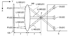
照明光学系の前面位置に、当該照明光学系の光軸に直交する仮想投影平面を定義したときに、個々の走査時点において、光拡散素子からの拡散光が上記仮想投影平面上に、一対の長辺と一対の短辺とを有する矩形状の拡散光スポットを形成するようにしたものである。(12) A twelfth aspect of the present invention is the lighting device according to the first aspect described above.
When a virtual projection plane orthogonal to the optical axis of the illumination optical system is defined at the front position of the illumination optical system, the diffused light from the light diffusing element is paired on the virtual projection plane at each scanning time point. A rectangular diffused light spot having a long side and a pair of short sides is formed.
(13) 本発明の第13の態様は、上述した第12の態様に係る照明装置において、
XYZ三次元直交座標系を定義したときに、照明対象面がXY平面上に設定され、光拡散素子の光放出面がXZ平面に平行な平面上に位置し、照明光学系の光軸が、光拡散素子の光放出面上の所定点から放出される拡散光の中心軸に平行になり、第1の拡散軸がX軸に平行になり、第2の拡散軸がZ軸に平行になり、
照明光学系の前面位置に、当該照明光学系の光軸に直交する仮想投影平面を定義したときに、個々の走査時点において、光拡散素子からの拡散光が上記仮想投影平面上に、X軸に平行な一対の長辺と他の一対の辺からなる短辺とを有する矩形状の拡散光スポットを形成するようにしたものである。(13) The thirteenth aspect of the present invention is the lighting device according to the twelfth aspect described above.
When the XYZ three-dimensional Cartesian coordinate system is defined, the illumination target plane is set on the XY plane, the light emission plane of the light diffusing element is located on the plane parallel to the XZ plane, and the optical axis of the illumination optical system is set. It becomes parallel to the central axis of the diffused light emitted from a predetermined point on the light emitting surface of the light diffusing element, the first diffusing axis becomes parallel to the X axis, and the second diffusing axis becomes parallel to the Z axis. ,
When a virtual projection plane orthogonal to the optical axis of the illumination optical system is defined at the front position of the illumination optical system, the diffused light from the light diffusing element is on the virtual projection plane on the X-axis at each scanning time point. A rectangular diffused light spot having a pair of long sides parallel to each other and a short side composed of another pair of sides is formed.
(14) 本発明の第14の態様は、上述した第12の態様に係る照明装置において、
XYZ三次元直交座標系を定義するとともに、X軸を回転軸としてZ軸を所定の傾斜角だけ回転させることにより得られるZ′軸を定義したときに、照明対象面がXY平面上に設定され、光拡散素子の光放出面がXZ′平面に平行な平面上に位置し、照明光学系の光軸がXZ′平面に直交し、第1の拡散軸がX軸に平行になり、第2の拡散軸がZ′軸に平行になり、
照明光学系の前面位置に、XZ′平面に平行な仮想投影平面を定義したときに、個々の走査時点において、光拡散素子からの拡散光が上記仮想投影平面上に、X軸に平行な一対の長辺とZ′軸に平行な一対の短辺とを有する矩形状の拡散光スポットを形成するようにしたものである。(14) The fourteenth aspect of the present invention is the lighting device according to the twelfth aspect described above.
When the XYZ three-dimensional Cartesian coordinate system is defined and the Z'axis obtained by rotating the Z axis by a predetermined tilt angle with the X axis as the rotation axis is defined, the illumination target surface is set on the XY plane. The light emission plane of the light diffusing element is located on a plane parallel to the XZ'plane, the optical axis of the illumination optical system is orthogonal to the XZ'plane, the first diffusing axis is parallel to the X axis, and the second The diffusion axis of is parallel to the Z'axis,
When a virtual projection plane parallel to the XZ'plane is defined at the front position of the illumination optical system, the diffused light from the light diffusing element is a pair parallel to the X axis on the virtual projection plane at each scanning time point. A rectangular diffused light spot having a long side and a pair of short sides parallel to the Z'axis is formed.
(15) 本発明の第15の態様は、上述した第1~第14の態様に係る照明装置において、
照明光学系がコリメートレンズによって構成されており、光拡散素子の光放出面が上記コリメートレンズの前側焦点位置に配置されているようにしたものである。(15) A fifteenth aspect of the present invention is the lighting device according to the first to fourteenth aspects described above.
The illumination optical system is composed of a collimating lens, and the light emitting surface of the light diffusing element is arranged at the front focal position of the collimating lens.
(16) 本発明の第16の態様は、上述した第1~第15の態様に係る照明装置において、
走査部材が、第1の面に入射した光を第2の面から射出する透過型走査体と、この透過型走査体を2軸まわりに回動して走査する走査機構と、を有し、
光源からの光ビームが上記透過型走査体を透過し、透過した光ビームが走査ビームとして光拡散素子へと向かうようにし、
走査制御部が、上記走査ビームの光拡散素子への入射点を二次元的に変化させる走査制御を行うようにしたものである。(16) The sixteenth aspect of the present invention is the lighting device according to the first to fifteenth aspects described above.
The scanning member has a transmissive scanning body that emits light incident on the first surface from the second surface, and a scanning mechanism that rotates the transmissive scanning body around two axes to scan.
The light beam from the light source is transmitted through the transmissive scanning body, and the transmitted light beam is directed toward the light diffusing element as a scanning beam.
The scanning control unit performs scanning control that two-dimensionally changes the incident point of the scanning beam on the light diffusing element.
(17) 本発明の第17の態様は、上述した第1~第15の態様に係る照明装置において、
走査部材が、入射した光を反射して射出する反射面を有する反射型走査体と、この反射型走査体を2軸まわりに回動して走査する走査機構と、を有し、
光源からの光ビームが上記反射型走査体を反射し、反射した光ビームが走査ビームとして光拡散素子へと向かうようにし、
走査制御部が、上記走査ビームの光拡散素子への入射点を二次元的に変化させる走査制御を行うようにしたものである。(17) The seventeenth aspect of the present invention is the lighting device according to the first to fifteenth aspects described above.
The scanning member has a reflective scanning body having a reflective surface that reflects and emits incident light, and a scanning mechanism that rotates and scans the reflective scanning body around two axes.
The light beam from the light source reflects the reflective scanning body, and the reflected light beam is directed toward the light diffusing element as a scanning beam.
The scanning control unit performs scanning control that two-dimensionally changes the incident point of the scanning beam on the light diffusing element.
(18) 本発明の第18の態様は、上述した第1~第17の態様に係る照明装置において、
走査制御部が、照明対象面上に形成された照明領域が、人間の目に連続した領域として視認される速度で走査を行うようにしたものである。(18) The eighteenth aspect of the present invention is the lighting device according to the first to seventeenth aspects described above.
The scanning control unit scans at a speed at which the illumination region formed on the illumination target surface is visually recognized as a continuous region by the human eye.
(19) 本発明の第19の態様は、上述した第1~第18の態様に係る照明装置において、
光源の点灯および消灯を制御する光点灯制御部を更に設け、
この光点灯制御部による点灯および消灯の制御が、走査制御部による走査制御に連動して行われるようにし、点灯時の描画スポットの集合体によって所定形状をもつ照明領域を形成するようにしたものである。(19) The 19th aspect of the present invention is the lighting device according to the 1st to 18th aspects described above.
A light lighting control unit that controls the lighting and extinguishing of the light source is further provided.
The lighting and extinguishing control by the light lighting control unit is performed in conjunction with the scanning control by the scanning control unit, and an illumination region having a predetermined shape is formed by a collection of drawing spots at the time of lighting. Is.
(20) 本発明の第20の態様は、上述した第1~第19の態様に係る照明装置を3組設けることによってカラー照明装置を構成し、
第1の照明装置の光源は赤色の光ビームを生成し、第2の照明装置の光源は緑色の光ビームを生成し、第3の照明装置の光源は青色の光ビームを生成し、
第1の照明装置の光拡散素子は赤色の拡散光によって赤色の照明領域を形成し、第2の照明装置の光拡散素子は緑色の拡散光によって緑色の照明領域を形成し、第3の照明装置の光拡散素子は青色の拡散光によって青色の照明領域を形成し、
上記赤色の照明領域、上記緑色の照明領域、および上記青色の照明領域の重複部分に所定色のカラー照明領域を形成するようにしたものである。(20) A twentieth aspect of the present invention constitutes a color lighting device by providing three sets of lighting devices according to the first to nineteenth aspects described above.
The light source of the first luminaire produces a red light beam, the light source of the second illuminator produces a green light beam, the light source of the third illuminator produces a blue light beam, and so on.
The light diffusing element of the first illuminating device forms a red illuminating area by the red diffused light, and the light diffusing element of the second illuminating device forms a green illuminating area by the green diffused light, and the third illuminating device. The light diffusing element of the device forms a blue illumination area by the blue diffused light,
A color illumination region of a predetermined color is formed in an overlapping portion of the red illumination region, the green illumination region, and the blue illumination region.
(21) 本発明の第21の態様は、上述した第1~第19の態様に係る照明装置または上述した第20の態様に係るカラー照明装置において、
車両に取り付けるための取付部を更に設け、照明対象面を路面上に設定し、上記車両から上記路面に対して照明を行うことができるようにしたものである。(21) The 21st aspect of the present invention is the lighting device according to the 1st to 19th aspects described above or the color lighting device according to the 20th aspect described above.
A mounting portion for mounting on a vehicle is further provided, and a surface to be illuminated is set on the road surface so that the vehicle can illuminate the road surface.
本発明に係る照明装置では、コヒーレントな光ビームが光拡散素子に照射され、そこからの拡散光によって照明対象面上に描画スポットが形成される。ここで、光ビームを走査すれば、移動する描画スポットによって所望の形状をもつ照明領域が描画される。しかも、光拡散素子が異方性拡散を行うため、拡散光の広がりが一方向に偏ることになる。このため、コヒーレント光に対する安全性を確保しつつ、照明対象面にボケを抑制した鮮明な照明領域を形成することができるようになる。 In the lighting device according to the present invention, a coherent light beam is applied to a light diffusing element, and a drawing spot is formed on an illuminated surface by the diffused light from the light diffusing element. Here, when the light beam is scanned, an illuminated area having a desired shape is drawn by the moving drawing spot. Moreover, since the light diffusing element performs anisotropic diffusion, the spread of the diffused light is biased in one direction. Therefore, it becomes possible to form a clear illumination region in which blurring is suppressed on the illumination target surface while ensuring safety against coherent light.
以下、本発明を図示する実施形態に基づいて説明する。なお、本願図面では、説明の便宜上、個々の構成要素の縮尺や縦横の寸法比等を、実際の部材のそれらから若干変更し、必要に応じて誇張して示してある。また、本願明細書に記載した個々の構成要素の形状や幾何学的条件、ならびにそれらを特定するために用いられている「平行」、「直交」、「同一」、「一致」、「矩形」等の用語、長さや角度の値等については、文言上の厳密な意味に縛られることなく、同様の機能を期待し得る程度の範囲を含めて解釈すべきものである。 Hereinafter, the present invention will be described based on the illustrated embodiment. In the drawings of the present application, for convenience of explanation, the scales and aspect ratios of the individual components are slightly changed from those of the actual members, and are exaggerated as necessary. In addition, the shapes and geometrical conditions of the individual components described herein, as well as the "parallel", "orthogonal", "identical", "match", and "rectangular" used to identify them. Terms such as, length and angle values should be interpreted to include the range in which similar functions can be expected without being bound by the strict meaning of the wording.
<<< §1. 車載型の照明装置の特徴 >>>
本発明に係る照明装置は、所定の照明対象面上に所定形状をもった照明領域を形成するのに適した装置であり、特に、路面上に所望の形状をもった照明パターンを形成する車載型の照明装置などへの用途に適している。このような用途では、照明光の光軸と照明対象面とのなす角が非常に小さくなるため、照明領域として提示される照明パターンが不鮮明になりやすい。本発明に係る照明装置では、このような用途においても、照明対象面上に鮮明な照明パターンを形成することが可能になる。そこで、この§1では、本発明の典型的な適用例として、路面上に所望の照明パターンを形成するための車載型の照明装置の特徴を簡単に述べておく。<<< §1. Features of in-vehicle lighting equipment >>>
The lighting device according to the present invention is a device suitable for forming a lighting region having a predetermined shape on a predetermined lighting target surface, and in particular, an in-vehicle device that forms a lighting pattern having a desired shape on a road surface. Suitable for applications such as type lighting equipment. In such an application, the angle formed by the optical axis of the illumination light and the illumination target surface becomes very small, so that the illumination pattern presented as the illumination area tends to be unclear. In the lighting device according to the present invention, it is possible to form a clear lighting pattern on the lighting target surface even in such an application. Therefore, in this §1, as a typical application example of the present invention, the characteristics of an in-vehicle lighting device for forming a desired lighting pattern on a road surface will be briefly described.
図1は、本発明に係る車載型の照明装置を用いた照明により、照明対象面となる路面10上に照明領域20を形成した一例を示す運転席からの俯瞰図である。この図は、車両(自動車)前方の路面10を、運転中の運転手から見た状態を示しており、路面前方の左側には、歩行者30が立っている。ここでは、説明の便宜上、図の右方向にX軸、図の奥行方向(車両の進行方向)にY軸を定義している。図1には示されていないが、路面10に対して直交する方向(鉛直方向)にはZ軸が定義される。
FIG. 1 is a bird's-eye view from the driver's seat showing an example in which a
図には、路面10上に矢印の形状をした照明領域20が形成されている例が示されている。この照明領域20は、車載型の照明装置からの照明光を路面10上に投影することにより得られたものであり、車両の走行とともに前方へ移動してゆくことになる。実際には、この照明領域20の内部の領域が照明されており、運転手や歩行者から見ると、路面10上に明るい領域として矢印図形の照明パターンが認識されることになる。この矢印図形の照明パターン(照明領域20)は、運転手もしくは歩行者30に対して、何らかの情報(たとえば、車両の進行方向)を提示するための路面上の指標として利用することができる。なお、照明領域20は、矢印図形に限定されるものではなく、後述する光ビームの走査により、任意の図形パターンや任意の文字パターンからなる照明領域20を形成することができる。
The figure shows an example in which an
本発明に係る照明装置の特徴は、照明対象面上に、任意の照明パターンを形成することができる点である。一般に夜間であれば、路面10上に形成された照明領域20は認識しやすいが、昼間の場合は、ある程度高い輝度で照明領域20が表示されるように、十分な照明強度を確保する必要がある。後述するように、本発明に係る照明装置には、レーザ光のようなコヒーレント光を放射するコヒーレント光源が用いられているため、十分な照明強度を確保することが可能である。
A feature of the lighting device according to the present invention is that an arbitrary lighting pattern can be formed on a surface to be illuminated. Generally, at night, the
なお、レーザ光のようなコヒーレント光は、一般の光に比べて放射強度がはるかに大きいため、観察者の目を損傷するおそれがある。たとえば、図1に示す例の場合、歩行者30や対向車の運転手などが、照明装置からの照明光を直視した場合でも、目に損傷を与える危険性がないような配慮が必要になる。本発明に係る照明装置の場合、後述するように、拡散光によって照明対象面を照らすようにしているため、照明光の単位面積当たりの光強度は十分に安全な程度にまで弱められる。このため、仮に歩行者30や対向車の運転手などが、照明装置の光源側を直視したとしても、強いコヒーレント光が人間の目に入ることはなく、人間の目を痛めるおそれはない。
It should be noted that coherent light such as laser light has a much higher radiant intensity than general light, and may damage the eyes of the observer. For example, in the case of the example shown in FIG. 1, it is necessary to take care so that there is no risk of damaging the eyes even when the
また、車載型の照明装置では、照明光の光軸と照明対象面(図示の例の場合、路面10)とのなす角が非常に小さくなるため、照明領域20として形成される照明パターンが不鮮明になりやすい。特に、路面10上に形成された照明パターンの奥の部分(図示の例の場合、矢印の先端部)および手前の部分(図示の例の場合、矢印の根元部)の輪郭にはボケが発生しやすい。本発明に係る照明装置は、このような問題に対処する機能も備えている。
Further, in an in-vehicle lighting device, the angle formed by the optical axis of the illumination light and the illumination target surface (
図2は、車載型の照明装置100からの照明により、路面10上に照明領域20(太線部分)を形成した一例を示す側面図である。この例では、車両(自動車)40は、路面10上を図の左から右へ向けて進行している。ここでは、図1と同様に、車両40の進行方向(図の右方向)にY軸を定義し、路面10に直交する方向(図の上方向)にZ軸を定義する。X軸は、図2には示されていないが、紙面垂直手前方向を向くことになる。
FIG. 2 is a side view showing an example in which a lighting region 20 (thick line portion) is formed on a
図示のとおり、車両40の前方には、本発明に係る照明装置100が取り付けられており、光軸Cに沿って路面10の前方が照明されている。ここに示す実施例における照明装置100は、ヘッドライト等とは別の装置であり、路面10上の所定の照明領域20を照明して、所定の照明パターンを提示する役割を果たす。ここに示す例の場合、照明領域20は、矢印形状の図形パターンになる。
As shown in the figure, a
図2に示す照明装置100は、自動車のヘッドライト等とは別の装置であるが、ヘッドライトとして利用することも可能であるし、ヘッドライトに組み込んで用いることも可能である。もちろん、この照明装置100は、自動車のテールライトやサーチライトなどの種々の照明灯として利用することも可能であり、これら種々の照明灯に組み込んで用いることも可能であるし、バンパー部などに取り付けて利用してもかまわない。
The
図2に示す車載型の照明装置100は、XY平面に位置する路面10上に任意形状の照明領域20を形成する機能を有している。運転手は、通常、路面10の進行方向に視線を向けている。したがって、照明領域20を運転手の視野の中心に入れるためには、路面10上のかなり遠方に照明領域20を形成する必要がある。たとえば、図2には、車両40の前方50m先の位置に、長手方向が10mにわたる照明領域20(太線部分)を形成した例が示されている。このような位置に照明領域20を形成する場合、照明装置100の設置高さを75cmとすると、光軸Cと路面10とのなす角θ(照明対象面に対する照射角)は、0.7°程度になる。図2では、便宜上、θの大きさをデフォルメして描いているが、実際には、光軸Cと路面10とのなす角度は極めて小さい。
The vehicle-mounted
このように、車載型の照明装置100は、一般的なプロジェクタなどと異なり、照明対象面に対する光の照射角θが極めて小さいという特徴がある。一般的なプロジェクタでは、照射角θの基準は90°であるため、上例のように照射角θが0.7°程度になるような使用形態は想定外である。したがって、一般的なプロジェクタに用いられている照明機構をそのまま車載用の照明装置に転用すると、投影面(照明対象面)上に鮮明な投影像を得ることが困難になる。
As described above, the vehicle-mounted
実際、図2に示す例のように、照明領域20のY軸方向の長さが10mに及ぶことになると、手前と奥との距離差が10mになるため、一般的なプロジェクタを用いた場合、照明領域20として提示される矩形パターンの輪郭線のすべてを鮮明に表示することは困難である。このため、運転手や歩行者30から見ると、路面10上に投影された照明パターンがボケているように観察される。照射角θが非常に小さいため、輪郭線のボケは、運転手から見て奥の部分(図2に示す照明領域20の右端)および手前の部分(図2に示す照明領域20の左端)において、特に顕著になる。
In fact, as in the example shown in FIG. 2, when the length of the
本発明に係る照明装置100では、後述するように、コヒーレントな光ビームを異方性拡散し、この拡散光によって照明対象面上に描画スポットを形成するようにし、光ビームを走査することによって描画スポットを移動させて所望の照明パターンからなる照明領域を形成する。このような異方性拡散は、後に詳述するように、照明領域の輪郭線のボケを抑制する上で効果的であり、また、コヒーレント光に対する安全性を確保する上でも効果的である。
In the
以上、本発明の典型的な適用例として、本発明を車載型の照明装置に適用した例を説明した。このような車載型の照明装置100には、車両40に取り付けるための取付部が設けられており、車両40の前方、後方、側方等に取り付けることにより、車両40から、路面10上に設定された照明対象面に対して照明を行うことが可能になる。
As described above, as a typical application example of the present invention, an example in which the present invention is applied to an in-vehicle lighting device has been described. Such an in-
もっとも、本発明に係る照明装置は、必ずしも車載型の照明装置に限定されるものではない。本発明に係る照明装置は、自動車、バイク、自転車等の車両だけでなく、船舶や飛行機、列車などを含む種々の乗物に搭載して利用することができる。また、本発明に係る照明装置は、このような乗物に搭載する用途だけでなく、様々な構造物に取り付けて、様々な情報を提示する用途にも利用可能である。たとえば、本発明に係る照明装置を、路面もしくは路面近傍に設置された構造物、または建物などに取り付ければ、各種案内標識や誘導標識を提示する用途に利用することも可能である。もちろん、本発明に係る照明装置によって照明領域が形成される照明対象面は、必ずしも平面である必要はなく、用途に応じて、曲面を照明対象面としてもかまわない。 However, the lighting device according to the present invention is not necessarily limited to the in-vehicle lighting device. The lighting device according to the present invention can be mounted and used not only on vehicles such as automobiles, motorcycles and bicycles, but also on various vehicles including ships, airplanes, trains and the like. Further, the lighting device according to the present invention can be used not only for mounting on such a vehicle but also for mounting on various structures and presenting various information. For example, if the lighting device according to the present invention is attached to a road surface or a structure installed near the road surface, a building, or the like, it can be used for presenting various guide signs and guidance signs. Of course, the illuminating target surface on which the illuminating region is formed by the illuminating device according to the present invention does not necessarily have to be a flat surface, and a curved surface may be used as the illuminating target surface depending on the application.
<<< §2. 基本的実施形態の全体構成 >>>
続いて、本発明の基本的実施形態の全体構成を説明する。図3は、本発明の基本的実施形態に係る照明装置100の基本構成を示す斜視図(一部はブロック図)である。この照明装置100は、§1で述べた車載型の装置であり、図2に示すように、車両40の前部に取り付けられ、照明対象面となる路面10上を照らして照明領域20を形成する機能を有している。<<< §2. Overall configuration of basic embodiment >>>
Subsequently, the overall configuration of the basic embodiment of the present invention will be described. FIG. 3 is a perspective view (partly a block diagram) showing a basic configuration of a
図3に示すとおり、この照明装置100は、光源110、走査部材120、光拡散素子130、照明光学系140、走査制御部150(ブロック図で示す)を備えており、所定の照明対象面S上に所定形状をもつ照明領域LAを形成して照明を行う。この例の場合、照明対象面Sは車両前方の路面であり、図3では、矢印図形の照明パターンからなる照明領域LAが形成された状態が示されている。なお、図3では、説明の便宜上、照明対象面Sの輪郭を矩形で示しているが、照明対象面Sは概念上の面であり、必ずしも矩形面である必要はない。また、上述したように、照明対象面Sは曲面であってもかまわない。
As shown in FIG. 3, the
ここでは、説明の便宜上、図示の各方向にX軸,Y軸,Z軸をとったXYZ三次元直交座標系を定義し、各構成要素の配置を、この座標系を参照しながら説明することにする。図3に示す座標系におけるX軸,Y軸,Z軸の向きは、図1および図2に示す各座標軸の向きと同じであり、Y軸は車両40の進行方向、X軸はこれに直交する横方向、Z軸は鉛直方向になる。X軸およびY軸は水平面上の軸になり、照明対象面S(路面10)はXY平面に相当する。
Here, for convenience of explanation, an XYZ three-dimensional Cartesian coordinate system having an X-axis, a Y-axis, and a Z-axis in each of the illustrated directions will be defined, and the arrangement of each component will be described with reference to this coordinate system. To. The directions of the X-axis, Y-axis, and Z-axis in the coordinate system shown in FIG. 3 are the same as the directions of the respective coordinate axes shown in FIGS. 1 and 2, the Y-axis is the traveling direction of the
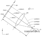
なお、Z′軸は、X軸を回転軸としてZ軸を所定の傾斜角ξだけ回転させること(X軸の負方向に向かって見たときに時計まわりに回転させること)により得られる軸である。したがって、XZ′平面は、XZ平面をX軸を回転軸として傾斜角ξだけ回転させて傾けた面になる。後述するように、光拡散素子130および照明光学系140は、このXZ′平面に平行な平面上に配置されている。
The Z'axis is an axis obtained by rotating the Z axis by a predetermined inclination angle ξ with the X axis as the rotation axis (rotating clockwise when viewed in the negative direction of the X axis). be. Therefore, the XZ'plane is a plane tilted by rotating the XZ plane by the tilt angle ξ with the X axis as the axis of rotation. As will be described later, the
光源110は、コヒーレントな光ビームL110を射出する構成要素であり、一般的には、レーザ光を射出するレーザ光源を用いればよい。レーザ光源には、様々なタイプのものがあるが、いずれのタイプのレーザ光源を用いてもかまわない。ここに示す実施例の場合、断面が直径数10μm程度の円形の光ビームL110を射出する半導体レーザを用いている。
The
走査部材120は、光源110からの光ビームL110を走査する構成要素である。図3には、走査部材120が、光ビームL110を一次元走査した例が示されている。具体的には、3つの走査時点t1,t2,t3について、走査後の光ビームL120(以下、走査ビームL120と呼ぶ)の光路が、それぞれ走査ビームL120(t1),走査ビームL120(t2),走査ビームL120(t3)として示されている。
The scanning
すなわち、走査時点t1において、光ビームL110は、走査ビームL120(t1)として光拡散素子130の入射点P(t1)に照射され、走査時点t2において、光ビームL110は、走査ビームL120(t2)として光拡散素子130の入射点P(t2)に照射され、走査時点t3において、光ビームL110は、走査ビームL120(t3)として光拡散素子130の入射点P(t3)に照射される。
That is, at the scanning time t1, the light beam L110 is irradiated to the incident point P (t1) of the
図示する実施例の場合、走査部材120は、第1の面に入射した光を第2の面から射出する透過型走査体(図に符号120で示されている構成要素)と、この透過型走査体を回動して走査する走査機構(モータや歯車などから構成される要素:図示省略)とを有している。透過型走査体としては、透明な板状部材やプリズムなどの屈折部材を用いることができる。これらの部材を回動することで、射出される光の進行方向を変化させることができる。上述した一次元走査を行う場合、Z′軸に平行な軸を回動軸として、走査機構により透過型走査体を回動軸まわりに回動させればよい。図に示す両方向矢印は、このような回動状態を示している。
In the case of the illustrated embodiment, the scanning
光拡散素子130は、XZ′平面に平行な平面上に配置されている平板状の構成要素であり、走査部材120が、上述した一次元走査(Z′軸に平行な軸まわりの回動走査)を行うと、走査ビームL120の光拡散素子130上の入射点Pは、図に破線で示すように、X軸に平行な走査線SLに沿って移動することになる。したがって、この場合、走査部材120は、光ビームをX軸方向に一次元走査することになる。走査部材120によって走査された走査ビームL120を受光した光拡散素子130は、受光した走査ビームL120を拡散させて、拡散光L130を放出する。図3には、走査時点t2において、入射点P(t2)に照射された走査ビームL120(t2)を拡散させることにより、拡散光L130(t2)が放出された状態が示されている。
The
図3には示されていないが、もちろん、走査時点t1においては、走査ビームL120(t1)の拡散光L130(t1)が入射点P(t1)から放出され、走査時点t3においては、走査ビームL120(t3)の拡散光L130(t3)が入射点P(t3)から放出される。 Although not shown in FIG. 3, of course, at the scanning time t1, the diffused light L130 (t1) of the scanning beam L120 (t1) is emitted from the incident point P (t1), and at the scanning time t3, the scanning beam is emitted. The diffused light L130 (t3) of L120 (t3) is emitted from the incident point P (t3).
ここで、重要な点は、光拡散素子130が、走査部材120によって走査されたコヒーレント光(走査ビームL120)を異方性拡散させる点である。ここで、異方性拡散とは、光拡散素子130の光放出面から二次元方向に等方的にコヒーレント光を拡散させるのではなく、所定方向に対するコヒーレント光の拡散範囲が、当該所定方向に交差する方向に対する拡散範囲よりも大きくなるように、コヒーレント光を拡散させることを意味する。より望ましくは、所定方向に対するコヒーレント光の拡散範囲を、当該所定方向に交差する方向に対する拡散範囲よりもはるかに大きくする。すなわち、光拡散素子130が、走査部材120で走査されたコヒーレント光(走査ビームL120)を、主に一軸方向に拡散させるようにすればよい。
Here, an important point is that the
別言すれば、図示のように、光拡散素子130の光放出面上に第1の拡散軸A1および第2の拡散軸A2を定義したときに、光拡散素子130が、第1の拡散軸方向A1への拡散光L130の広がりの程度を示す第1の拡散角度φ1と第2の拡散軸方向A2への拡散光の広がりの程度を示す第2の拡散角度φ2とが異なるような異方性拡散を行うようにする。図示の例の場合、光拡散素子130は、XZ′平面に平行な平面上に配置されており、第1の拡散軸A1は、X軸に平行な軸に設定され、第2の拡散軸A2は、Z′軸に平行な軸に設定されている。そして、第1の拡散角度φ1が第2の拡散角度φ2よりも大きくなるようにしている(たとえば、φ1がφ2の2倍以上、好ましくは5倍以上、更に好ましくは10倍以上になるようにする)。
In other words, as shown in the figure, when the first diffusion axis A1 and the second diffusion axis A2 are defined on the light emission surface of the
こうして、光拡散素子130から放出された拡散光L130は、照明光学系140に入射する。照明光学系140は、拡散光L130を照明対象面S(この例の場合、XY平面)へと導く光学系であり、ここに示す実施例の場合、コリメートレンズ(1枚の凸レンズ)を照明光学系140として用いている。もちろん、複数枚のレンズを組み合わせた光学系を照明光学系140として用いてもかまわない。
In this way, the diffused light L130 emitted from the
図示の例では、走査時点t2における拡散光L130(t2)が照明光学系140の前面に拡散光スポットG(t2)を形成した状態が示されている。この拡散光スポットG(t2)は、照明光学系140の前面位置(照明光学系140の光学作用を受ける前の位置)に定義された仮想投影平面上に形成されるスポットである。図示の実施例の場合、第1の拡散軸A1および第2の拡散軸A2は、互いに直交する軸になり、拡散光L130をその中心軸に直交する平面で切断した断面は矩形になる。このため、拡散光スポットG(t2)の形状も矩形になる。
In the illustrated example, a state in which the diffused light L130 (t2) at the scanning time t2 forms a diffused light spot G (t2) on the front surface of the illumination
こうして、照明光学系140を通過した拡散光L130(t2)は、照明光L140(t2)として照明対象面Sへと導かれ、この照明対象面S(XY平面)上に描画スポットD(t2)を形成する。描画スポットD(t2)は、拡散光スポットG(t2)を照明光学系140を通して照明対象面S上に投影したものになるので、若干変形されるものの、基本的には矩形に近い図形になる。しかも、この実施例の場合、X軸に沿った二辺を長辺、Y軸に沿った二辺を短辺とする矩形に近い図形になる。このような描画スポットD(t2)の形状は、§5で詳述するように、照明領域LA(図示の例の場合、矢印図形の照明パターン)のボケを低減する上で重要である。
In this way, the diffused light L130 (t2) that has passed through the illumination
図3には、走査時点t2において、拡散光スポットG(t2)に基づいて描画スポットD(t2)が形成された例が示されているが、もちろん、走査時点t1においては、拡散光スポットG(t1)に基づく描画スポットD(t1)が形成され、走査時点t3においては、拡散光スポットG(t3)に基づく描画スポットD(t3)が形成される。図示のような一次元走査を行うと、走査ビームL120の光拡散素子130への入射点Pは、X軸に平行な走査線SLに沿って移動するので、照明対象面S上に形成される描画スポットDも、この走査に応じて、ほぼX軸に沿って移動することになる。
FIG. 3 shows an example in which the drawing spot D (t2) is formed based on the diffused light spot G (t2) at the scanning time t2, but of course, at the scanning time t1, the diffused light spot G is shown. The drawing spot D (t1) based on (t1) is formed, and at the scanning time t3, the drawing spot D (t3) based on the diffused light spot G (t3) is formed. When one-dimensional scanning as shown in the figure is performed, the incident point P of the scanning beam L120 on the
このように、走査部材120による走査を行うと、個々の走査時点において、異方性拡散によって得られた拡散光L130が、照明光学系140を通して照明対象面S上に描画スポットDを形成することになる。しかも、この描画スポットDの形成位置は、個々の走査時点によって異なるので、個々の走査時点で得られる個々の描画スポットDの和集合として、所定形状をもつ照明領域LAが形成されることになる。
In this way, when scanning is performed by the scanning
図3には、このような描画スポットDの和集合として、矢印図形の照明パターンからなる照明領域LAが形成された状態が示されている。実際には、このような矢印図形の照明パターンを形成するためには、二次元走査が必要になる。もちろん、一次元走査によっても、X軸に沿った線状の照明パターンを形成することは可能であり、走査部材120による走査方向は、一次元方向でもよいし、二次元方向でもよい。ただ、任意形状の図形や文字などからなる照明領域LAを形成する上では、実用上は、走査部材120に二次元走査の機能をもたせておくのが好ましい。
FIG. 3 shows a state in which an illumination region LA composed of an illumination pattern of an arrow figure is formed as a union of such drawing spots D. In reality, two-dimensional scanning is required to form the illumination pattern of such an arrow figure. Of course, it is possible to form a linear illumination pattern along the X-axis by one-dimensional scanning, and the scanning direction by the scanning
もちろん、二次元走査を行った場合でも、得られる照明領域LAの解像度は、描画スポットDのサイズによる制限を受けることになるので、図3に例示したサイズの描画スポットDによって、図3に照明領域LAとして例示する矢印図形の矢尻の先鋭部を正確に描くことは困難であるが、描画スポットDのサイズを小さくすれば、二次元走査によって、より解像度の高い任意形状のパターンを描画することが可能になる。以下の説明では、光拡散素子130の入射面が二次元平面上に広がっており、この入射面の二次元方向に沿って、走査部材130がコヒーレント光を繰り返し走査させる例を説明する。
Of course, even when two-dimensional scanning is performed, the resolution of the obtained illumination area LA is limited by the size of the drawing spot D. Therefore, the drawing spot D having the size illustrated in FIG. 3 illuminates FIG. It is difficult to accurately draw the sharp edge of the arrowhead of the arrow figure exemplified as the region LA, but if the size of the drawing spot D is reduced, a pattern of an arbitrary shape with higher resolution can be drawn by two-dimensional scanning. Will be possible. In the following description, an example will be described in which the incident surface of the
図4は、図3に示す光拡散素子130上における二次元走査の例を示す平面図である。ここに示す二次元走査の方式は、一般にラスター走査と呼ばれている方式であり、CRTディスプレイにおける電子線の走査に利用されている。具体的には、まず、走査時点t11において、左上隅の入射点P(t11)に走査ビームL120を入射させ、この位置にビームスポットBを形成する。ここに示す例は、光源110から円形断面をもつ光ビームL110が射出された場合の例であり、光拡散素子130上の入射点P(t11)の位置には、破線で示すように、ほぼ円形のビームスポットBが形成される。
FIG. 4 is a plan view showing an example of two-dimensional scanning on the
ここで、走査部材120によって第1の拡散軸A1方向への一次元走査を行うと、ビームスポットBは、走査線SL1に沿って左から右へと移動してゆき、走査時点t12において、入射点P(t12)の位置へ到達する。続いて、ビームスポットBを左端の入射点P(t11)より1行分下の位置へと戻し、再び、左から右への走査を行った後に左端の1行分下の位置へと戻し、... という操作を順に繰り返してゆく。最後に、最下行の左端の入射点P(t31)の位置から走査線SL3に沿って左から右へと移動させ、右端の入射点P(t32)の位置へ到達すれば、1フレーム分の走査が完了する。
Here, when one-dimensional scanning is performed in the direction of the first diffusion axis A1 by the scanning
1フレーム分の走査が完了したら、ビームスポットBを右下隅の入射点P(t32)から左上隅の入射点P(t11)の位置へ戻し、再び、1フレーム分の走査を行う(あるいは、入射点P(t32)から入射点P(t11)へと、前回の1フレーム分の走査の経路を逆に辿って戻るようにしてもよい)。図3に示す入射点P(t1)→P(t2)→P(t3)への走査線SLは、図4に示す入射点P(t21)→P(t22)→P(t23)への走査線SL2に相当する。 After scanning for one frame is completed, the beam spot B is returned from the incident point P (t32) in the lower right corner to the incident point P (t11) in the upper left corner, and scanning for one frame is performed again (or incident). It is also possible to reverse the scanning path of the previous one frame from the point P (t32) to the incident point P (t11). The scanning line SL from the incident point P (t1) → P (t2) → P (t3) shown in FIG. 3 is a scan from the incident point P (t21) → P (t22) → P (t23) shown in FIG. Corresponds to line SL2.
この図4に示す例のように、走査ビームL120の入射点Pが、光拡散素子130の全領域に渡るようなラスター走査を行うと、照明対象面S上に形成される描画スポットDも同様に二次元走査されることになる。したがって、この場合、照明対象面S上には、ほぼ矩形状の照明領域(図3に示す矩形状の照明対象面Sのような矩形領域)が形成されることになる。図3に示すような矢印図形の照明領域LAを形成するには、光拡散素子130の全領域に渡るラスター走査ではなく、矢印図形に対応する部分領域内のみを走査すればよい(§6.1で述べる変形例を採用すれば、光源110に対する光点灯制御を行うことにより、全領域に渡るラスター走査を行いつつ、矢印図形等の任意のパターンからなる照明領域LAを形成できる)。
As in the example shown in FIG. 4, when the raster scanning is performed so that the incident point P of the scanning beam L120 covers the entire region of the
任意の図形パターンや文字パターンからなる照明領域LAを形成するには、上述したラスター走査の代わりに、ベクター走査を行うと便利である。ベクター走査は、光拡散素子130上に定義された任意のベクトルに沿ってビームスポットBを移動させる走査である。走査部材120に、二次元走査を行う機能をもたせておけば、第1の拡散軸A1方向への走査量と第2の拡散軸A2方向への走査量とを組み合わせることにより、ビームスポットBを光拡散素子130上の任意の位置へ移動させることが可能になる。すなわち、光拡散素子130上でビームスポットBが任意の軌跡を描くような走査が可能になる。
In order to form an illuminated area LA composed of an arbitrary graphic pattern or character pattern, it is convenient to perform vector scanning instead of the raster scanning described above. The vector scan is a scan in which the beam spot B is moved along an arbitrary vector defined on the
図3にブロックとして示された走査制御部150は、実際には、電子回路やコンピュータによって構成され、走査ビームL120の光拡散素子130への入射点Pが所定の軌跡を描くように、走査部材120の走査を制御する役割を果たす。照明対象面S上に任意形状の照明領域LAを形成するには、当該任意形状のパターンを描画することができるように、走査制御部150が、走査ビームL120の光拡散素子130への入射点Pを二次元的に変化させる走査制御を行うようにすればよい。そうすれば、照明対象面S上で描画スポットDを移動させて描画を行うことができ、所定形状をもつ照明領域LAを形成することができる。
The
もちろん、描画スポットDの移動速度が遅ければ、人間の目から見ると、矩形状の描画スポットDが移動しているように認識されてしまうので、実際には、走査制御部150は、照明対象面S上に形成される照明領域LAが、人間の目に連続した領域として視認される速度で走査を行うようにする。
Of course, if the moving speed of the drawing spot D is slow, the rectangular drawing spot D will be perceived as moving by the human eye. Therefore, the
<<< §3. 光拡散素子の構成 >>>
ここでは、図3に示す照明装置100における光拡散素子130の構成について、より詳細な説明を行う。<<< §3. Configuration of light diffusing element >>>
Here, the configuration of the
<3.1 回折現象によって拡散光を生成する光拡散素子>
既に§2で述べたとおり、本発明における光拡散素子130は、走査部材120によって走査された走査ビームL120を受光し、これを拡散させて拡散光L130を放出する構成要素であり、第1の拡散軸A1の方向への拡散光の広がりの程度(前述した実施例の場合、第1の拡散角度φ1)と、第2の拡散軸A2の方向への拡散光の広がりの程度(前述した実施例の場合、第2の拡散角度φ2)とが異なるような異方性拡散を行うという特徴を有している。<3.1 Light diffusing element that generates diffused light by diffraction phenomenon>
As already described in §2, the
このような特徴をもった異方性拡散を行う光拡散素子130としては、たとえば、回折光学素子(DOE:Diffractive Optical Element)や、ホログラフィック光学素子(HOE:Holographic Optical Element)などを用いることができる。この他、光拡散素子130は、マイクロレンズアレイやレンチキュラーレンズ、拡散板などで構成してもよい。もちろん、マイクロレンズアレイやレンチキュラーレンズの機能を回折光学素子に組み込むことにより、マイクロレンズアレイやレンチキュラーレンズと同等の機能を有する回折光学素子を用いるようにしてもよい。
As the
ここでは、光拡散素子130を、回折光学素子もしくはホログラフィック光学素子によって構成した例を詳述する。これらの素子は、光の回折現象によって拡散光を生成するものであり、記録する回折パターンの構成を工夫することにより回折角度を調整して、所望の異方性拡散の特性を実現することができる。以下、光の回折現象によって生じる異方性拡散の実態を、もう少し詳しく説明する。
Here, an example in which the
図5は、変位角θV,θHを用いて、光拡散素子130上の1点Pから放出される1次回折光強度の角度空間分布を表現する方法を示す図である。なお、光拡散素子130からは、0次回折光や2次以上の回折光も放出されるが、実用上、1次回折光の強度が支配的になるため、ここでは、1次回折光のみを考慮することにする。以下、光拡散素子130の回折面(光放出面)がXZ平面上に配置されているものとし、所定の入射角度で入射光Linを与えた場合に、座標(xp,yp,zp)に位置する回折面上の1点P(xp,yp,zp)から射出する1次回折光Lout の向きを考える。
FIG. 5 is a diagram showing a method of expressing an angular spatial distribution of the primary diffracted light intensity emitted from one point P on the
図5(a) は、XYZ三次元直交座標系を上方から見た投影図(XY平面への投影図)であり、図の右方がY軸正方向、図の下方がX軸正方向、図の紙面に垂直な手前方向がZ軸正方向になる。そして、光拡散素子130は、この座標系のXZ平面上に配置されている。ここで、この光拡散素子130上の点Pに所定の方向から入射光Linを与えた場合に、点Pから1次回折光として射出する射出光Lout の光路(破線)を考えてみる。図5(a) には、点Pから射出された1次回折光Lout(破線)が、三次元空間上の任意の点Q(xq,yq,zq)に向かう様子が示されている。
FIG. 5A is a projection drawing (projection view onto the XY plane) of the XYZ three-dimensional Cartesian coordinate system viewed from above. The front direction perpendicular to the paper surface of the figure is the Z-axis positive direction. The
図示の例の場合、1次回折光Lout は、点Pに立てた法線Np(Y軸に平行)に対して第1方向変位角θHをなす方向に射出している。この第1方向変位角θHは、入射光Linについての水平方向(XY平面に平行な水平面に沿った方向)の変位角に相当し、ここでは、図5(a) に示す投影図において、反時計まわりの方向を第1方向変位角θHの正の方向にとることにする(図示の変位角θHは負の値をとることになる)。 In the case of the illustrated example, the primary diffracted light Lout is emitted in a direction forming a first-direction displacement angle θH with respect to the normal Np (parallel to the Y-axis) set at the point P. This first-direction displacement angle θH corresponds to the displacement angle in the horizontal direction (direction along the horizontal plane parallel to the XY plane) with respect to the incident light Lin, and here, in the projection diagram shown in FIG. The clockwise direction is taken in the positive direction of the first direction displacement angle θH (the shown displacement angle θH has a negative value).
一方、図5(b) は、XYZ三次元直交座標系を側方から見た投影図(YZ平面への投影図)であり、図の右方がY軸正方向、図の上方がZ軸正方向、図の紙面に垂直な手前方向がX軸正方向になる。上述したとおり、光拡散素子130は、この座標系のXZ平面上に配置されている。ここでも、この光拡散素子130上の点Pに所定の方向から入射光Linを与えた場合に、点Pから1次回折光として射出する射出光Lout の光路(破線)を考えてみる。この図5(b) でも、点Pから射出された1次回折光Lout(破線)が、三次元空間上の点Q(図5(a) に示す点Qと同一の点)に向かう様子が示されている。
On the other hand, FIG. 5 (b) is a projection view (projection view on the YZ plane) of the XYZ three-dimensional Cartesian coordinate system viewed from the side. The positive direction and the front direction perpendicular to the paper in the figure are the positive X-axis directions. As described above, the
図示の例の場合、1次回折光Lout は、点Pに立てた法線Np(Y軸に平行)に対して第2方向変位角θVをなす方向に射出している。この第2方向変位角θVは、入射光Linについての垂直方向(Z軸に平行な方向)の変位角に相当し、ここでは、図5(b) に示す投影図において、反時計まわりの方向を第2方向変位角θVの正の方向にとることにする(図示の変位角θVは負の値をとることになる)。 In the case of the illustrated example, the primary diffracted light Lout is emitted in a direction forming a second-direction displacement angle θV with respect to the normal Np (parallel to the Y-axis) set at the point P. This second direction displacement angle θV corresponds to the displacement angle in the vertical direction (direction parallel to the Z axis) with respect to the incident light Lin, and here, in the projection diagram shown in FIG. 5 (b), the counterclockwise direction. Is taken in the positive direction of the second direction displacement angle θV (the illustrated displacement angle θV has a negative value).
このように、光拡散素子130の任意の1点Pから射出される1本の回折光Lout の進行方向(回折方向)は、第1方向変位角θHと第2方向変位角θVという2組の角度によって表現することができる。すなわち、点P(xp,yp,zp)から点Q(xq,yq,zq)に向かう回折光の向きは、(θH,θV)なる2組の角度によって表現できる。
In this way, the traveling direction (diffraction direction) of one diffracted light Lout emitted from any one point P of the
したがって、ある1点Pから射出する1次回折光の向きは、図5(c) に示すように、二次元直交座標系θH-θVで表現される角度空間分布図上の分布点Rの位置座標によって示すことができる。図5(c) に示す分布点Rは、この分布図における横座標値θH(R),縦座標値θV(R)で示される座標にプロットされた点であり、図5(a) ,(b) に示す射出光Lout の向きを示している。図5(a) ,(b) に示す光拡散素子130の回折面(XZ平面)を、図の右方向から観察した場合(法線Npの矢印とは逆方向に観察した場合)、点QのXZ平面への投影像は、点Pの左下に位置することになる。図5(c) に示す分布点Rは、図5(a) ,(b) に示す点Qに対応するものであり、やはり点Pの左下に位置している。
Therefore, as shown in FIG. 5 (c), the direction of the primary diffracted light emitted from a certain point P is the position coordinates of the distribution point R on the angular spatial distribution map represented by the two-dimensional Cartesian coordinate system θH−θV. Can be indicated by. The distribution point R shown in FIG. 5 (c) is a point plotted at the coordinates indicated by the abscissa value θH (R) and the coordinate value θV (R) in this distribution map, and FIGS. The direction of the emission light Lout shown in b) is shown. When the diffraction plane (XZ plane) of the
以上、説明の便宜上、光拡散素子130上の幾何学的な1点Pに入射光Linが入射し、この入射光Linが向きを変えて1本の射出光Lout として射出される例を示したが、実際には、光拡散素子130に入射する走査ビームL120は、図4に示すように、ある程度の面積をもったビームスポットBを形成する。このため、ある走査時点において光拡散素子130上で生じる光学現象は、1点Pの近傍領域にビームスポットBが照射され、当該近傍領域に形成されている回折パターンにより、当該近傍領域全体から拡散光L130が広がってゆく現象ということになる。したがって、実際には、図5(a) ,(b) に示すように、点Pから1本の射出光Lout が射出されるわけではなく、点P近傍から、ある程度の広がり幅をもった拡散光L130が放出されることになる。
As described above, for convenience of explanation, an example is shown in which the incident light Lin is incident on the geometrical point P on the
図5(c) に示す二次元直交座標系θH-θV上の各分布点Rについて、それぞれ所定の強度値を定めたものは、点Pの近傍の回折パターンによって回折される1次回折光強度の角度空間分布を示す情報になり、これは当該点Pの近傍の回折パターンの回折特性を示す情報になる。たとえば、図5(c) に示す分布点R(θH(R),θV(R))の位置にのみ強度値100が定義され、それ以外の部分にはすべて強度値0が定義された1次回折光強度の角度空間分布をもつ光拡散素子130は、図5(a) ,(b) に示すように、入射光Linに対して、強度値100をもつた1本の射出光Linのみを1次回折光として射出する回折特性を有する素子ということになる。
For each distribution point R on the two-dimensional Cartesian coordinate system θH-θV shown in FIG. 5 (c), the one in which a predetermined intensity value is determined is the primary diffraction light intensity diffracted by the diffraction pattern in the vicinity of the point P. The information indicates the angular spatial distribution, which is the information indicating the diffraction characteristics of the diffraction pattern in the vicinity of the point P. For example, the
もちろん、1次回折光強度の角度空間分布は、入射光Linの入射角に応じて変わる。図5(a) ,(b) に示す例の場合、入射角=0°であるが、この入射角を変化させると、射出光Lout の向きも変化し、第1方向変位角θHおよび第2方向変位角θVも変化し、図5(c) に示す角度空間分布も変化する。したがって、図5(c) に示す角度空間分布は、入射光Linを、ある特定の入射角で点Pの近傍に照射したときに得られる1次回折光の強度の角度空間分布を示している。 Of course, the angular spatial distribution of the primary diffracted light intensity changes depending on the incident angle of the incident light Lin. In the case of the examples shown in FIGS. 5 (a) and 5 (b), the incident angle = 0 °, but when this incident angle is changed, the direction of the emitted light Lout also changes, and the first-direction displacement angle θH and the second The directional displacement angle θV also changes, and the angular spatial distribution shown in FIG. 5 (c) also changes. Therefore, the angular spatial distribution shown in FIG. 5 (c) shows the angular spatial distribution of the intensity of the primary diffracted light obtained when the incident light Lin is irradiated in the vicinity of the point P at a specific incident angle.
<3.2 光拡散素子の垂直配置>
図6は、XZ平面上に配置された光拡散素子130上の点P近傍に入射光Linが与えられたときに、当該点P近傍から放出される拡散光L130の様子を示す図である。図6(a) は、図5(a) と同様に、XYZ三次元直交座標系を上方から見た投影図(XY平面への投影図)であり、図の右方がY軸正方向、図の下方がX軸正方向、図の紙面に垂直な手前方向がZ軸正方向になる。一方、図6(b) は、図5(b) と同様に、XYZ三次元直交座標系を側方から見た投影図(YZ平面への投影図)であり、図の右方がY軸正方向、図の上方がZ軸正方向、図の紙面に垂直な手前方向がX軸正方向になる。上述したとおり、光拡散素子130は、この座標系のXZ平面上に配置されている。<3.2 Vertical arrangement of light diffusing elements>
FIG. 6 is a diagram showing a state of the diffused light L130 emitted from the vicinity of the point P when the incident light Lin is given in the vicinity of the point P on the
この図6に示す例の場合、光拡散素子130の回折面(XZ平面)の点P近傍に所定の入射角(この例の場合、入射角=0°)をもつ入射光Linを与えると、X軸方向(水平方向)に関しては、図6(a) に示すように、法線Npを中心として第1の拡散角度φ1で広がり、Z軸方向(垂直方向)に関しては、図6(b)に示すように、法線Npより下方に向かうように第2の拡散角度φ2で広がる拡散光L130が得られる。図にハッチングを施して示す領域が、拡散光L130の回折範囲ということになる。なお、図6(a) ,(b) では、便宜上、1点Pから拡散光L130が広がってゆく状態が描かれているが、実際には、入射光Linとして照射された光ビームによって形成されるビームスポットBに応じた点Pの近傍領域全体から、拡散光L130が放出されることになる。
In the case of the example shown in FIG. 6, when the incident light Lin having a predetermined incident angle (incident angle = 0 ° in this example) is given to the vicinity of the point P on the diffraction surface (XZ plane) of the
結局、光拡散素子130の点P近傍の領域には、図6(a) ,(b) に示す拡散光L130を回折光として生じるような回折特性を有する回折パターンが形成されていることになる。この回折特性は、図6(c) に示す1次回折光強度の角度空間分布として示すことができる。図6(c) には、矩形状の回折光分布領域E(ハッチング部分)が示されているが、この回折光分布領域Eは、第1方向変位角θHおよび第2方向変位角θVの特定の範囲を示すものであり、その横幅は第1の拡散角度φ1、縦幅は第2の拡散角度φ2に相当する。
After all, in the region near the point P of the
なお、1次回折光強度の角度空間分布は、図6(c) に示す二次元座標系の各座標位置にそれぞれ所定の強度値を定義したものになる。すなわち、図6(c) には、回折光分布領域Eがハッチングを施した矩形領域として描かれているが、1次回折光強度の角度空間分布は、各部分に所定の強度値を定義したものになる。たとえば、図6(c) における回折光分布領域Eの内部に強度値100が定義され、それ以外の部分に強度値0が定義された1次回折光強度の角度空間分布をもつ光拡散素子130の場合、図6(a) ,(b) にハッチングを施して示す領域にのみ強度値100をもった1次回折光が進行し、それ以外の領域には1次回折光は全く進行しないことになる。
The angular spatial distribution of the primary diffracted light intensity defines a predetermined intensity value at each coordinate position of the two-dimensional coordinate system shown in FIG. 6 (c). That is, in FIG. 6 (c), the diffracted light distribution region E is drawn as a hatched rectangular region, but the angular spatial distribution of the primary diffracted light intensity defines a predetermined intensity value for each portion. become. For example, the
図6(c) に示す回折光分布領域Eが、縦軸θVを中心軸として左右対称になっているのは、図6(a) に示すように、拡散光L130が法線Npを中心とする対称形となるように広がっているためである。また、図6(c) に示す回折光分布領域Eが、原点Pよりも下方の位置(座標値θVが負の値となる位置)に配置されているのは、図6(b) に示すように、拡散光L130が法線Npよりも下方に向かって進行するためである。このように、拡散光L130が下方に向かって進行すれば、照明対象面となるXY平面を照明するために好都合である。 The diffracted light distribution region E shown in FIG. 6 (c) is bilaterally symmetric with the vertical axis θV as the central axis, because the diffused light L130 is centered on the normal Np as shown in FIG. 6 (a). This is because it spreads so as to have a symmetrical shape. Further, the diffracted light distribution region E shown in FIG. 6 (c) is arranged at a position below the origin P (a position where the coordinate value θV is a negative value), as shown in FIG. 6 (b). This is because the diffused light L130 travels downward from the normal Np. As described above, if the diffused light L130 travels downward, it is convenient for illuminating the XY plane to be illuminated.
図6に示す例は、光拡散素子130の光放出面(回折面)をXZ平面上に配置した例である。このように、光拡散素子130の光放出面をXZ平面もしくはXZ平面に平行な平面(本願では、XZ平面自身も含めて、単に、XZ平面に平行な平面と言う)上に配置すれば、光拡散素子130の光放出面は照明対象面(XY平面)に対して直交することになる。そこで、本願では、このような光拡散素子130の配置を「垂直配置」と呼ぶことにする。
The example shown in FIG. 6 is an example in which the light emitting surface (diffraction surface) of the
図2に示すような車載型の照明装置100において、光拡散素子130を垂直配置し、路面10を照明対象面として照明する場合、照明光の光軸Cを斜め下方に向ける必要がある。したがって、垂直配置を採用する実施例の場合、図6(b) に示すように、拡散光L130が下方に向かって進行するような回折特性を光拡散素子130にもたせておくと便利である。図6(c) に示す回折光分布領域Eは、このような配慮のもとに設計された光拡散素子130の回折特性を示すものである。
In the vehicle-mounted
図6(b) に示すように、拡散光L130は下方に向かって進行するため、照明光学系140は、この進行方向に配置するのが好ましい。また、照明光学系140は、その主面が拡散光L130の中心軸に対して直交する向きに配置するのが好ましい。なお、図6(b) に示す例では、入射光Linは法線Npの方向に入射しているので、光源110の光軸も法線Npに一致させれば、光源110、走査部材120、光拡散素子130を一直線上に配置することが可能になり、全体的に単純な構造をもった照明装置を実現できる。
As shown in FIG. 6B, since the diffused light L130 travels downward, it is preferable to arrange the illumination
もちろん、光源110や走査部材120は、設計上の都合に合わせて任意の位置に配置することができる。たとえば、図6(a) ,(b) では、入射光Lin(走査ビームL120)が入射面に対して垂直に入射する例を示したが、入射光Linの入射方向は入射面に対して必ずしも垂直にする必要はないので、光源110および走査部材120は、必ずしも法線Npを通る直線上に配置する必要はない。
Of course, the
光拡散素子130に対する入射光Lin(走査ビームL120)の向きを任意の方向に設定した場合でも、光拡散素子130に記録する回折パターンを調整すれば、図6(a) ,(b) に示す拡散光L130と全く同じ方向に向かう拡散光を得ることができる。したがって、本発明を実施する上で、光源110および走査部材120の配置は、特に限定されるものではない。ただ、光拡散素子130から放出される拡散光L130は、予め設定した照明対象面の方向へ向かうようにする必要があるので、光拡散素子130を設計する上では、入射光Lin(走査ビームL120)の入射方向を予め定めておき、当該方向から入射する入射光Linが照明対象面へ向かうような回折特性をもった回折パターンを光拡散素子130に記録しておくのが好ましい。
Even when the direction of the incident light Lin (scanning beam L120) with respect to the
<3.3 光拡散素子の傾斜配置>
一方、図7は、拡散素子130の光放出面(回折面)をXZ平面に対して傾斜させるように配置した例を示す側方投影図である。図に一点鎖線で示すZ′軸は、X軸を回転軸としてZ軸を所定の傾斜角ξだけ回転させることにより得られる軸である。この例の場合も、照明対象面はXY平面上に設定されているが、拡散素子130は、その光放出面(回折面)がXZ′平面もしくはXZ′平面に平行な平面(本願では、XZ′平面自身も含めて、単に、XZ′平面に平行な平面と言う)上に位置する。本願では、このような光拡散素子130の配置を「傾斜配置」と呼ぶことにする。<3.3 Inclined arrangement of light diffusing elements>
On the other hand, FIG. 7 is a side projection drawing showing an example in which the light emitting surface (diffraction surface) of the
図2に示すような車載型の照明装置100において、光拡散素子130を傾斜配置し、路面10を照明対象面として照明する場合、照明光の光軸Cを斜め下方に向ける必要があるが、図7に示す傾斜角ξを、図2に示す照射角θに一致させておけば、光拡散素子130の光放出面上の点Pに立てた法線Np′の方向を、図2に示す光軸Cの方向に一致させることができる。
In the vehicle-mounted
図7は、図6(b) と同様に、XYZ三次元直交座標系を側方から見た投影図(YZ平面への投影図)であり、図の右方がY軸正方向、図の上方がZ軸正方向、図の紙面に垂直な手前方向がX軸正方向になるが、光拡散素子130は、この座標系のXZ平面を傾斜させたXZ′平面上に配置されている。したがって、この図7は、XZ′平面上に配置された光拡散素子130上の点P近傍に入射光Linが与えられたときに、当該点P近傍から放出される拡散光L130の様子を示す図になっている。
FIG. 7 is a projection view (projection view on the YZ plane) of the XYZ three-dimensional Cartesian coordinate system viewed from the side, as in FIG. 6 (b). The upper part is the positive direction of the Z axis, and the front direction perpendicular to the paper surface of the figure is the positive direction of the X axis. The
この図7に示す光拡散素子130のX軸方向に関する拡散特性は、図6(a) に示す例と全く同様である。したがって、傾斜配置された光拡散素子130は、所定の入射角(この例の場合、入射角=0°)をもつ入射光Linが与えられたときに、X軸方向に関しては、図6(a) に示すように、法線Np(実際には、図7に示す法線Np′)を中心として第1の拡散角度φ1で広がり、Z′軸方向に関しては、図7に示すように、法線Np′を中心として第2の拡散角度φ2で広がる拡散光L130を放出することになる。なお、図7では、便宜上、1点Pから拡散光L130が広がってゆく状態が描かれているが、実際には、入射光Linとして照射された光ビームによって形成されるビームスポットBに応じた点Pの近傍領域全体から、拡散光L130が放出されることになる。
The diffusion characteristics of the
このような回折特性は、図7の右上の枠内に示す1次回折光強度の角度空間分布として示すことができる。この分布図には、矩形状の回折光分布領域E(ハッチング部分)が示されているが、この回折光分布領域Eは、第1方向変位角θHおよび第2方向変位角θVの特定の範囲を示すものであり、その横幅は第1の拡散角度φ1、縦幅は第2の拡散角度φ2に相当する。 Such diffraction characteristics can be shown as an angular spatial distribution of the primary diffraction light intensity shown in the upper right frame of FIG. 7. In this distribution map, a rectangular diffracted light distribution region E (hatched portion) is shown, and this diffracted light distribution region E is a specific range of the first direction displacement angle θH and the second direction displacement angle θV. The horizontal width corresponds to the first diffusion angle φ1 and the vertical width corresponds to the second diffusion angle φ2.
図6(c) に示す例(垂直配置の実施例)における回折光分布領域Eも、図7に示す例(傾斜配置の実施例)における回折光分布領域Eも、縦軸θVを中心軸として左右対称の矩形になっているが、これは、図6(a) に示すように、拡散光L130が法線Npを中心とした対称形になるように広がっているためである。 Both the diffracted light distribution region E in the example shown in FIG. 6 (c) (example of vertical arrangement) and the diffracted light distribution region E in the example shown in FIG. 7 (example of tilted arrangement) have the vertical axis θV as the central axis. The rectangular shape is symmetrical, because, as shown in FIG. 6A, the diffused light L130 spreads so as to have a symmetrical shape centered on the normal Np.
一方、図6(c) に示す回折光分布領域Eは、原点Pよりも下方の位置(座標値θVが負の値となる位置)に配置されているのに対し、図7に示す回折光分布領域Eは、原点Pを中心に配置されている。これは、垂直配置の実施例の場合、図6(b) に示すように、拡散光L130を照明対象面(XY平面)に向かわせるために下方に回折させているのに対して、傾斜配置の場合、図7に示すように、光拡散素子130自身が傾斜して配置されており、その法線Np′が照明対象面(XY平面)に向いているため、第2方向変位角θVは0°に近くても、拡散光L130が法線Np′に沿って照明対象面(XY平面)に向かうためである。
On the other hand, the diffracted light distribution region E shown in FIG. 6 (c) is arranged at a position below the origin P (a position where the coordinate value θV is a negative value), whereas the diffracted light shown in FIG. 7 is located. The distribution region E is arranged around the origin P. In the case of the example of the vertical arrangement, as shown in FIG. 6B, the diffused light L130 is diffracted downward in order to direct it toward the illumination target surface (XY plane), whereas the inclined arrangement is performed. In the case of, as shown in FIG. 7, since the
図3に示す基本的実施形態に係る照明装置100は、傾斜配置を採用した実施例に対応し、光拡散素子130の光放出面(回折面)および照明光学系140の光学的な主面は、XZ′平面に平行な平面上に配置されている。そして、光源110の光軸が照明光学系140の光軸に一致するように配置されており、光拡散素子130には、図7の右上枠内に示すような回折特性をもった回折パターンが記録されている。このため、光源110、走査部材120、光拡散素子130、照明光学系140を、一直線上に配置することができ、全体的に単純な構造をもった照明装置が実現されている。
The
<3.4 本発明に用いる光拡散素子の特徴>
これまで、光拡散素子130を垂直配置する場合の回折特性として、図6(c) に示す角度空間分布を例示し、光拡散素子130を傾斜配置する場合の回折特性として、図7に示す角度空間分布を例示したが、このような回折特性を採用するのは、拡散光L130をXY平面上に定義された照明対象面に導きやすくするための配慮である。したがって、本発明を実施するにあたり、必ずしも図6(c) や図7に示す回折特性を採用する必要はない。<3.4 Features of the light diffusing element used in the present invention>
So far, the angular spatial distribution shown in FIG. 6 (c) has been exemplified as the diffraction characteristic when the
たとえば、照明光学系140に、光拡散素子130からの拡散光L130を曲げたり、反射したりして照明対象面へと導く機能を設けておけば、光拡散素子130からの拡散光L130が照明対象面に向かって放出されていなくても、照明光学系140によって、これを照明対象面へと導くことが可能である。ただ、上述したような回折特性を採用すれば、照明光学系140として1枚の単純なコリメートレンズを用いただけでも、拡散光L130を照明対象面へと効率的に導くことができ、照明光学系140の構成を単純化することができる。
For example, if the illumination
本発明に用いる光拡散素子130の重要な特徴は、光放出面上に定義された第1の拡散軸A1方向への拡散光の広がりの程度を示す第1の拡散角度φ1と第2の拡散軸A2方向への拡散光の広がりの程度を示す第2の拡散角度φ2とが異なるような異方性拡散を行う点にある。このような異方性拡散によって、コヒーレント光に対する安全性を確保しつつ、照明対象面にボケを抑制した鮮明な照明領域を形成するという固有の作用効果が得られるのである(その理由は、§5で説明する)。
An important feature of the
特に、これまで述べてきた実施例は、第1の拡散軸A1および第2の拡散軸A2として互いに直交する軸を設定した例である。たとえば、図6に示す垂直配置の実施例の場合、第1の拡散軸A1はX軸に平行な軸になり、第2の拡散軸A2はZ軸に平行な軸になり、両軸は直交している。そして、第1の拡散角度φ1は、第2の拡散角度φ2よりも大きくなるように設定されており、回折光分布領域Eは横長の矩形になる。一方、図7に示す傾斜配置の実施例の場合、第1の拡散軸A1はX軸に平行な軸になり、第2の拡散軸A2はZ′軸に平行な軸になり、やはり両軸は直交している。ここでも、第1の拡散角度φ1は、第2の拡散角度φ2よりも大きくなるように設定されており、回折光分布領域Eは横長の矩形になる。 In particular, the examples described so far are examples in which axes orthogonal to each other are set as the first diffusion axis A1 and the second diffusion axis A2. For example, in the case of the vertical arrangement embodiment shown in FIG. 6, the first diffusion axis A1 is an axis parallel to the X axis, the second diffusion axis A2 is an axis parallel to the Z axis, and both axes are orthogonal to each other. is doing. The first diffusion angle φ1 is set to be larger than the second diffusion angle φ2, and the diffracted light distribution region E becomes a horizontally long rectangle. On the other hand, in the case of the example of the inclined arrangement shown in FIG. 7, the first diffusion axis A1 becomes an axis parallel to the X axis, the second diffusion axis A2 becomes an axis parallel to the Z'axis, and both axes also. Are orthogonal. Here, too, the first diffusion angle φ1 is set to be larger than the second diffusion angle φ2, and the diffracted light distribution region E becomes a horizontally long rectangle.
このように、回折光分布領域Eが矩形になるような回折特性をもった光拡散素子130からの拡散光L130を、その中心軸に直交する平面で切断すると、矩形の断面が得られる。図8は、図7に示す光拡散素子130から放出される拡散光L130を、XZ′平面に平行な平面で切断した断面図である。図4に示すように、光拡散素子130の入射面に等方的なほぼ円形のビームスポットBが照射された場合であっても、ビームスポットBが形成される領域の回折特性が図7の右上枠内の分布図になっていれば、光拡散素子130から放出される拡散光L130の断面は、図8に示すような矩形になる。図6に示す光拡散素子130から放出される拡散光L130を、その中心軸に直交する平面で切断した場合も、やはり矩形の断面が得られることになる。
As described above, when the diffused light L130 from the
図6(a) ,(b) および図7には、光拡散素子130の光放出面(回折面)上の特定の点Pから回折光として放出される拡散光L130が示されているが、光拡散素子130の放出面上のいずれの点についても、図6(c) もしくは図7の右上枠内に示す角度空間分布に応じた拡散光が得られるように、光拡散素子130の全面にわたって所定の回折パターンを形成しておけば、光放出面上のいずれの位置からも、図6(a) ,(b) または図7に示す方向に拡散光が放出されることになる。
6 (a), 6 (b) and 7 show diffused light L130 emitted as diffracted light from a specific point P on the light emitting surface (diffraction surface) of the
図6に示す垂直配置の実施例は、XYZ三次元直交座標系を定義したときに、照明対象面がXY平面上に設定され、光拡散素子130の光放出面がXZ平面に平行な平面上に位置し、第1の拡散軸A1がX軸に平行になり、第2の拡散軸A2がZ軸に平行になる実施例ということになる。そして、光拡散素子130の異方性拡散により、光放出面から放出された拡散光L130は、照明対象面となるXY平面へと向かい、この拡散光L130をその中心軸に直交する平面で切断したときの断面は、X軸に平行な二辺を長辺、他の二辺を短辺とする矩形になる。
In the example of the vertical arrangement shown in FIG. 6, when the XYZ three-dimensional Cartesian coordinate system is defined, the illumination target plane is set on the XY plane, and the light emission plane of the
一方、図7に示す傾斜配置の実施例は、XYZ三次元直交座標系を定義するとともに、X軸を回転軸としてZ軸を所定の傾斜角ξだけ回転させることにより得られるZ′軸を定義したときに、照明対象面がXY平面上に設定され、光拡散素子130の光放出面がXZ′平面に平行な平面上に位置し、第1の拡散軸A1がX軸に平行になり、第2の拡散軸A2がZ′軸に平行になる実施例ということになる。そして、光拡散素子130の異方性拡散により、光放出面から放出された拡散光L130は、照明対象面となるXY平面へと向かい、この拡散光L130をその中心軸に直交する平面(XZ′平面に平行な平面)で切断したときの断面は、X軸に平行な二辺を長辺、他の二辺(Z′軸に平行な二辺)を短辺とする矩形になる。
On the other hand, the example of the tilt arrangement shown in FIG. 7 defines an XYZ three-dimensional Cartesian coordinate system and defines a Z'axis obtained by rotating the Z axis by a predetermined tilt angle ξ with the X axis as the rotation axis. At that time, the illumination target surface is set on the XY plane, the light emission surface of the
図3に示す例の場合、光拡散素子130の異方性拡散によって、X軸に平行な二辺を長辺とする矩形断面をもつ拡散光L130が得られており、照明対象面S上には、X軸に平行な二辺を長辺、Y軸に平行な二辺を短辺とする矩形状の描画スポットDが投影されている。このように長辺と短辺の長さの比が大きい描画スポットDを走査して所望の照明パターンを描画すれば、コヒーレント光に対する安全性を確保しつつ、照明対象面にボケを抑制した鮮明な照明領域を形成することができる(§5参照)。
In the case of the example shown in FIG. 3, diffused light L130 having a rectangular cross section having two sides parallel to the X-axis as long sides is obtained by anisotropic diffusion of the
光拡散素子130を、回折光学素子(DOE)もしくはホログラフィック光学素子(HOE)によって構成する場合、光拡散素子130の各部分には、所定の入射角をもつ入射光Linが与えられたときに、所定の1次回折光強度の角度空間分布をもった回折光が拡散光L130として放出されるような回折格子もしくは干渉縞を記録しておけばよい。
When the
具体的には、所定の入射点Pへの入射光Linに対する回折光の変位角度を、第1の拡散軸方向A1への変位を示す第1方向変位角θHと第2の拡散軸方向A2への変位を示す第2方向変位角θVとによって表し、第1方向変位角θHを横座標軸にとり、第2方向変位角θVを縦座標軸にとり、第1方向変位角=0、第2方向変位角=0となる点を原点Pにとった分布グラフを定義したときに、この分布グラフ上において、1次回折光強度の角度空間分布が、縦座標軸を対称軸として左右対称をなす横長の矩形からなる回折光分布領域Eによって表されるような回折特性をもった回折格子もしくは干渉縞を記録しておけばよい。 Specifically, the displacement angle of the diffracted light with respect to the incident light Lin to the predetermined incident point P is set to the first direction displacement angle θH indicating the displacement in the first diffusion axis direction A1 and the second diffusion axis direction A2. The first direction displacement angle θH is taken as the horizontal coordinate axis, the second direction displacement angle θV is taken as the vertical coordinate axis, and the first direction displacement angle = 0, the second direction displacement angle =. When a distribution graph is defined with the point of 0 as the origin P, on this distribution graph, the angular spatial distribution of the primary diffraction light intensity is diffraction consisting of horizontally long rectangles symmetrical with the vertical coordinate axis as the axis of symmetry. A diffraction grid or interference fringes having diffraction characteristics as represented by the light distribution region E may be recorded.
図6に示す垂直配置の実施例の場合、光拡散素子130の各部分についての1次回折光強度の角度空間分布は、図6(c) に示すように、分布グラフ上において、縦座標軸を中心として、拡散光L130が照明対象面(XY平面)へと向かうような所定の縦座標値(負のθVの値)をもつ位置に配置された横長の矩形からなる回折光分布領域Eによって表されることになる。
In the case of the example of the vertical arrangement shown in FIG. 6, the angular spatial distribution of the primary diffracted light intensity for each part of the
これに対して、図7に示す傾斜配置の実施例の場合、光拡散素子130の各部分についての1次回折光強度の角度空間分布は、図7の右上枠内に示すように、分布グラフ上において、原点Pを中心として配置された横長の矩形からなる回折光分布領域Eによって表されることになる。図7の右上枠内に示す角度空間分布において、回折光分布領域Eの横幅φ1に比べて、縦幅φ2を十分に小さくする設計を行うのであれば、光拡散素子130には、実質的に水平方向(第1方向変位角θHの方向)にのみ回折を行う機能をもたせておけばよい。この場合、光拡散素子130を回折格子によって構成することができる。
On the other hand, in the case of the example of the inclined arrangement shown in FIG. 7, the angular spatial distribution of the primary diffracted light intensity for each part of the
図9は、図7に示す光拡散素子130を回折格子を利用して形成した例を示す平面図(図(a) )および側断面図(図(b) )である。この光拡散素子130は、図示のとおり、Z′軸に平行な多数の格子線131を複数通りのピッチで配置した回折格子を物理的構造体に記録した回折光学素子によって構成されている。図9(a) の平面図に示すとおり、各格子線131はいずれもZ′軸に平行な方向に形成されているが、そのピッチは様々になっている。図示の例の場合、中央部分の格子線ピッチは大きく、左右両端へゆくほど、格子線ピッチは徐々に小さくなっている。
9 is a plan view (FIG. (A)) and a side sectional view (FIG. (B)) showing an example in which the
また、図9(b) の側断面図に示すとおり、回折格子は、鋸歯状の物理的凹凸構造によって構成されており、しかも鋸歯を構成する傾斜面の向きは、右半分と左半分とで逆になっている。このため、同一方向から入射光Linを与えたとしても、回折する方向(X軸の正方向か負方向か)は右半分と左半分とで異なることになる。また、格子線のピッチも様々であるため、X軸方向への回折角も様々になる。結局、このような物理的構造をもつ回折格子を光拡散素子130として利用すれば、入射光LinをX軸方向の所定範囲内(図6(a) に示す第1の拡散角度φ1内)に回折することができる。
Further, as shown in the side sectional view of FIG. 9B, the diffraction grating is composed of a sawtooth-shaped physical uneven structure, and the orientations of the inclined surfaces constituting the sawtooth are the right half and the left half. It's the other way around. Therefore, even if the incident light Lin is given from the same direction, the direction of diffraction (whether the positive direction or the negative direction of the X-axis) is different between the right half and the left half. Further, since the pitch of the grid lines is also various, the diffraction angle in the X-axis direction is also various. After all, if a diffraction grating having such a physical structure is used as the
図9に示す光拡散素子130は、入射光LinをZ′軸方向に回折する機能を有していないが、実際には、図9(a) に破線の円で示すように、光拡散素子130への入射光Linは、ある程度面積をもったビームスポットBとして照射されるため、光拡散素子130からの拡散光L130は、Z′軸方向にもある程度広がった光になる。なお、図9では、説明の便宜上、格子線131のピッチがビームスポットBの寸法に比べて拡大されて描かれているが、実際の格子線ピッチは光の波長程度の寸法であり、ビームスポットB内に、様々なピッチをもつ多数の格子線が含まれることになる。したがって、ビームスポットBとして与えられた入射光Linは、X軸方向に様々な回折角をもって回折し、第1の拡散角度φ1内に広がることになる。
The
以上、図9を参照しながら、光拡散素子130を回折格子によって構成した実施例を説明したが、光拡散素子130を、ホログラフィック光学素子(HOE)によって構成すれば、より自由度の高い回折特性をもたせることが可能になる。たとえば、光拡散素子130を、個々の部分がそれぞれ所定位置に矩形面の再生像を生成するホログラフィック光学素子によって構成すれば、断面形状が矩形の拡散光L130を任意の方向に放出させることが可能である。
Although the embodiment in which the
たとえば、図3に示す例において、矩形状の拡散光スポットG(t2)をホログラム再生像として生成するための干渉縞を、光拡散素子130の入射点P(t2)の近傍領域に記録しておけば、走査時点t2において、入射点P(t2)の近傍に走査ビームL130(t2)を再生用照明光として照射すれば、図示する拡散光スポットG(t2)の位置に、矩形状のホログラム再生像が得られることになる。要するに、光拡散素子130には、入射光を第1の拡散軸A1の方向には大きく拡散し、これに交差する第2の拡散軸A2の方向には小さく拡散(たとえば、ビームスポットB程度の拡散)するような回折特性をもったホログラムが記録されていればよい。
For example, in the example shown in FIG. 3, an interference fringe for generating a rectangular diffused light spot G (t2) as a hologram reproduction image is recorded in a region near the incident point P (t2) of the
なお、このような矩形状のホログラム再生像を生成する機能をもった光拡散素子130は、たとえば、図3の拡散光スポットG(t2)の位置に矩形面を有する拡散板を配置し、図3の光拡散素子130の位置に感光性媒体(ブランクのホログラム記録材料)を配置し、走査ビームL130(t2)と同じビームを参照光として与え、拡散板からの物体光と参照光とによって生じた干渉縞を感光性媒体に記録する光学的な方法によって作成することができる。ただ、実用上は、CGH(Computer Generated Hologram)の手法を利用して作成するのが好ましい。
In the
CGHの手法を利用すれば、物体光を発生させる拡散板やこれを照明する光源、干渉縞を形成するための光学系、干渉縞を記録するための感光性媒体などを用意する必要がなく、干渉縞の記録工程をすべてコンピュータ上の演算によって行うことができる。このため、任意の回折特性を持つ干渉縞を簡易な手順で低コストにて再現性よく生成できる。たとえば、図4に示すように、等方的なビームスポットBとして、ほぼ円形の領域にコヒーレント光が照射された場合に、図8に示すような矩形断面をもつ拡散光L130が放出されるような異方性拡散を行う干渉縞の情報をコンピュータによって演算し、演算により得られた干渉縞をホログラム記録媒体に記録すればよい。 If the CGH method is used, it is not necessary to prepare a diffuser plate that generates object light, a light source that illuminates the diffuser plate, an optical system for forming interference fringes, and a photosensitive medium for recording interference fringes. The entire process of recording interference fringes can be performed by calculation on a computer. Therefore, interference fringes having arbitrary diffraction characteristics can be generated at low cost and with good reproducibility by a simple procedure. For example, as shown in FIG. 4, as an isotropic beam spot B, when coherent light is applied to an almost circular region, diffused light L130 having a rectangular cross section as shown in FIG. 8 is emitted. Information on the interference fringes that perform anisotropic diffusion may be calculated by a computer, and the interference fringes obtained by the calculation may be recorded on a hologram recording medium.
CGHの手法を利用して作成された光拡散素子130は、コンピュータによる演算によって求められた干渉縞を有するCGHを、物理的構造体に記録したホログラフィック光学素子ということになる。このようなCGHの手法を利用したホログラフィック光学素子の作成方法は公知の技術であるため、ここでは詳細な説明は省略する。
The
<<< §4. 照明領域の形成 >>>
ここでは、図3に示す照明装置100において、光拡散素子130から放出された拡散光L130が照明光学系L140を通って照明対象面S(XY平面)に照射され、描画スポットDを形成し、更に、この描画スポットDを走査することにより、照明対象面S上に所定形状をもつ照明領域LAを形成するプロセスを詳述する。<<< §4. Formation of illuminated area >>>
Here, in the
光拡散素子130の各位置から放出された拡散光L130は、いずれも図8に示すように断面が矩形形状をなす。そして、照明光学系140は、その光軸がXZ′軸に直交する向きに配置されている。したがって、図3に示すように、照明光学系140の位置に形成される拡散光スポットGも、拡散光L130の断面に相似した矩形形状になる。図3に示す実施例の場合、照明光学系140はコリメートレンズ(1枚の凸レンズ)によって構成されており、光拡散素子130の光放出面がこのコリメートレンズの前側焦点位置に配置されている。
As shown in FIG. 8, the diffused light L130 emitted from each position of the
図4に示すように、走査部材120による走査を受けて、ビームスポットBは、光拡散素子130上を移動する。このため、光拡散素子130から放出される拡散光L130も移動し、照明光学系140の位置に形成される拡散光スポットGも移動する。図10は、図4に示す走査を行った場合に、照明光学系140に入射する拡散光L130によって形成される拡散光スポットGの移動状態を示す平面図であり、図4に示す走査時点t11~t32に対応させて、矩形状の拡散光スポットG(t11)~G(t32)が形成される状態が示されている。
As shown in FIG. 4, the beam spot B moves on the
なお、ここに示す実施例の場合、照明光学系140はレンズから構成されており、その入射面は湾曲面になる。したがって、拡散光L130の断面が図8に示すような矩形であったとしても、レンズの入射面(湾曲面)に形成されるスポットは、正確な矩形にはならない。そこで、本願では、便宜上、照明光学系140(レンズ)の前面位置に、照明光学系140の光軸に直交する仮想投影平面Mを定義し、拡散光L130によってこの仮想投影平面M上に投影されるスポットを拡散光スポットGと定義することにする。
In the case of the embodiment shown here, the illumination
図10に一点鎖線で描かれている枠は、この仮想投影平面Mを示している。仮想投影平面Mは、照明光学系140(レンズ)の直前に配置され、照明光学系140の光軸に直交している。図示されている矩形状の拡散光スポットG(t11)~G(t32)は、いずれもこの仮想投影平面M上に位置している。また、光拡散素子130の任意の位置から放出される拡散光L130の断面は、いずれも、図8に示すように、X軸に平行な2辺を長辺とし、他の2辺を短辺とする矩形になる。したがって、図10に示す各拡散光スポットG(t11)~G(t32)も、X軸に平行な2辺を長辺とし、他の2辺を短辺とする矩形になる。
The frame drawn by the alternate long and short dash line in FIG. 10 indicates this virtual projection plane M. The virtual projection plane M is arranged immediately before the illumination optical system 140 (lens) and is orthogonal to the optical axis of the illumination
図10に示す拡散光スポットGの移動軌跡は、図4に示すビームスポットBの移動軌跡に応じたものになる。図示の例は、ラスター走査を行う例であり、拡散光スポットGは、走査線SL1,... ,SL2,... ,SL3,... に沿って二次元的に移動することになる。なお、図10は図4の走査と連動して拡散光スポットGが移動することを概念的に示すための図であり、拡散光スポットG(t11)~G(t32)の位置は、必ずしも正確なものではない。 The movement locus of the diffused light spot G shown in FIG. 10 corresponds to the movement locus of the beam spot B shown in FIG. The illustrated example is an example of performing raster scanning, and the diffused light spot G moves two-dimensionally along the scanning lines SL1, ..., SL2, ..., SL3, ... .. Note that FIG. 10 is a diagram for conceptually showing that the diffused light spot G moves in conjunction with the scanning of FIG. 4, and the positions of the diffused light spots G (t11) to G (t32) are not always accurate. It's not something like that.
要するに、ここに示す実施例の場合、照明光学系140の前面位置に、照明光学系140の光軸に直交する仮想投影平面Mを定義したときに、個々の走査時点において、光拡散素子130からの拡散光L130によって、仮想投影平面M上に、一対の長辺と一対の短辺とを有する矩形状の拡散光スポットGが形成されることになる。
In short, in the case of the embodiment shown here, when the virtual projection plane M orthogonal to the optical axis of the illumination
図3に示す照明装置100は、§3.3で述べた「光拡散素子の傾斜配置」の実施例に相当するものである。この「光拡散素子の傾斜配置」の実施例では、XYZ三次元直交座標系を定義するとともに、X軸を回転軸としてZ軸を所定の傾斜角ξだけ回転させることにより得られるZ′軸を定義したときに、光拡散素子130がXZ′平面に平行な平面上に配置され、照明対象面SがXY平面上に設定され、第1の拡散軸A1がX軸に平行になり、第2の拡散軸A2がZ′軸に平行になる。また、照明光学系140は、その光軸がXZ′軸に直交する向きに配置されている。
The
このため、照明光学系140の前面位置に、XZ′平面に平行な仮想投影平面Mを定義すれば、個々の走査時点において、光拡散素子130の個々の位置から放出される拡散光L130は、仮想投影平面M上に、X軸に平行な一対の長辺とZ′軸に平行な一対の短辺とを有する矩形状の拡散光スポットGを形成することになる。図10に示されている拡散光スポットG(t11)~G(t32)は、いずれもX軸に平行な一対の長辺とZ′軸に平行な一対の短辺とを有する矩形になっている。
Therefore, if a virtual projection plane M parallel to the XZ'plane is defined at the front position of the illumination
図11は、図3に示す照明装置100における光拡散素子130から得られる拡散光L130が、照明光学系140を経て照明対象面Sに到達する光路の一例を示す側面図である。照明光学系140は、光拡散素子130によって異方性拡散された拡散光L130(コヒーレント光)を照明対象面Sへと導びく役割を果たす。光拡散素子130は、理想的には照明光学系140の前側焦点位置に配置するのが好ましい。図11に示す例は、このような理想的な配置を行った例であり、光拡散素子130の拡散面(回折面)と照明光学系140(レンズ)の主面との距離が、照明光学系140の焦点距離fに一致するように設定されている。
FIG. 11 is a side view showing an example of an optical path in which the diffused light L130 obtained from the
一方、照明対象面Sは、通常、照明光学系140の後側焦点位置Fよりも遠くに位置する。たとえば、図2に示すような車載型の照明装置の場合、照明対象面Sは、路面10上のかなり遠方に設定される。図11では、走査時点t11において、光拡散素子130の点P(t11)から放出された拡散光L130(t11)の光路が破線で示され、走査時点t21において、点P(t21)から放出された拡散光L130(t21)の光路が実線で示され、走査時点t31において、点P(t31)から放出された拡散光L130(t31)の光路が一点鎖線で示されている。したがって、照明対象面S上には、走査時点t11において破線で示す照明光L140(t11)が到達し、走査時点t21において実線で示す照明光L140(t21)が到達し、走査時点t31において一点鎖線で示す照明光L140(t31)が到達する。
On the other hand, the illumination target surface S is usually located farther than the rear focal position F of the illumination
なお、図11に示す各光路は、拡散光L130や照明光L140の中心軸を示すものであり、実際には、拡散光L130および照明光L140は所定の幅をもった光になる。ここに示す実施例の場合、照明光学系140はコリメートレンズによって構成されており、光拡散素子130からの拡散光L130を平行化するコリメータとして機能する。このコリメートレンズ140に対する拡散光L130の入射位置は、図10に示すように、各走査時点t11~t31によって異なる。
Each optical path shown in FIG. 11 indicates the central axis of the diffused light L130 and the illumination light L140, and the diffused light L130 and the illumination light L140 are actually light having a predetermined width. In the case of the embodiment shown here, the illumination
ただ、光拡散素子130がコリメートレンズ140の前側焦点位置に配置されているため、コリメートレンズ140のどの位置に拡散光L130が入射しても、コリメートレンズ140は入射した拡散光L130を平行化して射出する。したがって、たとえば、図に破線で示す拡散光L130(t11)は、所定の拡散角度で広がる光になるが、照明光学系140を通ることにより平行化され、照明対象面Sへと向かう照明光L140(t11)は平行化された光になる。このため、照明対象面Sがかなり遠方に設定されていた場合でも、ほぼ矩形形状を維持した描画スポットDを形成することができる。
However, since the
図12は、図11に示す各構成要素を、視線方向V(図11の右上参照)から観察した状態を示す投影図である。この図では、走査時点t21において、光拡散素子130の点P(t21)から放出された拡散光L130(t21)の光路が破線で示され、走査時点t22において、点P(t22)から放出された拡散光L130(t22)の光路が実線で示され、走査時点t23において、点P(t23)から放出された拡散光L130(t23)の光路が一点鎖線で示されている。したがって、照明対象面S上には、走査時点t21において破線で示す照明光L140(t21)が到達して描画スポットD(t21)が形成され、走査時点t22において実線で示す照明光L140(t22)が到達して描画スポットD(t22)が形成され、走査時点t23において一点鎖線で示す照明光L140(t23)が到達して描画スポットD(t23)が形成される。
FIG. 12 is a projection drawing showing a state in which each component shown in FIG. 11 is observed from the line-of-sight direction V (see the upper right of FIG. 11). In this figure, the optical path of the diffused light L130 (t21) emitted from the point P (t21) of the
このように、コリメートレンズ140から射出する照明光L140の進行方向は、コリメートレンズ140のどの位置に拡散光L130が入射したかによって異なってくる。図11に示すように、拡散光L130の入射位置をZ′軸方向に変化させると、照明対象面Sに形成される描画スポットDの位置はY軸方向に変化し、図12に示すように、拡散光L130の入射位置をX軸方向に変化させると、照明対象面Sに形成される描画スポットDの位置はX軸方向に変化する。
As described above, the traveling direction of the illumination light L140 emitted from the
図8に示すように、拡散光L130の断面は、X軸に平行な2辺を長辺とする矩形になるため、拡散光L130のX軸方向への広がりは、Z′軸方向への広がりに比べて顕著になる。このため、図12では、拡散光L130(t21),拡散光L130(t22),拡散光L130(t23)の光路をそれぞれ広がりをもった光路として描いている。上述したように、照明光学系140はコリメートレンズによって構成されているため、照明光学系140を通った照明光L140(t21),拡散光L140(t22),拡散光L140(t23)は平行化され、照明対象面Sに到達する。その結果、図12に示すとおり、照明対象面S上に形成される描画スポットDも矩形になる。
As shown in FIG. 8, since the cross section of the diffused light L130 is a rectangle having two sides parallel to the X axis as long sides, the spread of the diffused light L130 in the X axis direction is spread in the Z'axis direction. It becomes remarkable compared to. Therefore, in FIG. 12, the optical paths of the diffused light L130 (t21), the diffused light L130 (t22), and the diffused light L130 (t23) are drawn as wide optical paths, respectively. As described above, since the illumination
以上、図3に示す照明装置100を例にとりながら、§3.3で述べた「光拡散素子の傾斜配置」の実施例における照明領域LAの形成プロセスを説明したが、§3.2で述べた「光拡散素子の垂直配置」の実施例における照明領域LAの形成プロセスもほぼ同様である。
The process of forming the illumination region LA in the embodiment of the “tilted arrangement of the light diffusing element” described in §3.3 has been described above by taking the
「光拡散素子の垂直配置」の実施例の場合、図6に示すように、XYZ三次元直交座標系を定義したときに、光拡散素子130がXZ平面に平行な平面上に配置され、照明対象面SがXY平面上に設定され、第1の拡散軸A1がX軸に平行になり、第2の拡散軸A2がZ軸に平行になる。このとき、照明光学系140は、その光軸が光拡散素子130の放出面上の所定点P(たとえば、放出面の中心点)から放出される拡散光L130の中心軸に平行になるような向きに配置するのが好ましい。より好ましくは、照明光学系140は、その光軸が光拡散素子130の放出面上の所定点Pから放出される拡散光L130の中心軸に一致するように配置するとよい。
In the case of the embodiment of "vertical arrangement of light diffusing elements", as shown in FIG. 6, when the XYZ three-dimensional Cartesian coordinate system is defined, the
この場合、照明光学系140の前面位置に、その光軸に直交する仮想投影平面Mを定義すると、図10に示す例と同様に、個々の走査時点において、光拡散素子130からの拡散光L130が、仮想投影平面M上に、X軸に平行な一対の長辺と他の一対の辺からなる短辺とを有する矩形状の拡散光スポットGを形成することになる。したがって、照明対象面S上にも、矩形状の描画スポットDを形成することができる。
In this case, if a virtual projection plane M orthogonal to the optical axis is defined at the front position of the illumination
このように、図3に示す照明装置100では、走査部材120の走査に応じて、照明光学系140(コリメートレンズ)に入射するコヒーレント光の入射位置が変化する。そして、コリメートレンズ140上のコヒーレント光の入射位置および入射角度に応じて、コリメートレンズ140から射出されるコヒーレント光の進行方向も変化する。その結果、照明対象面S上に形成される描画スポットDの位置も変化する。したがって、走査制御部150によって走査部材120の走査を制御することにより、照明対象面S上で描画スポットDを移動させ、任意形状のパターンからなる照明領域LAを形成することができる。
As described above, in the
以上、照明光学系140として1枚のコリメートレンズ(凸レンズ)を用いる例を述べたが、もちろん、複数枚のレンズを組み合わせたコリメート光学系を照明光学系140として用いてもかまわない。また、照明光学系140は必ずしもレンズで構成する必要はなく、同等の機能を果たす凹面鏡などの曲面ミラーを用いて構成してもよい。凹面鏡を照明光学系140として用いた場合でも、光拡散素子130を凹面鏡の焦点位置に配置するようにすれば、凹面鏡で反射されたコヒーレント光は、ほぼ平行な方向に進行し、照明対象面Sに到達することになる。
Although the example of using one collimating lens (convex lens) as the illumination
<<< §5. 本発明に固有の作用効果 >>>
既に述べたとおり、図3に示す照明装置100は、描画スポットDを移動させることにより、照明対象面S上に任意の形状をもつ照明領域LAを描くことができる。照明対象面S上に、矢印のパターンからなる照明領域LAを描画するためには、図13に示すように、光拡散素子130上の矢印状の走査領域SAの内部(ハッチングを施した部分)のみに、ビームスポットBが照射されるような走査を行えばよい。前述したとおり、このような走査は、ラスター走査で行うこともできるし、ベクター走査で行うこともできる。<<< §5. Actions and effects unique to the present invention >>>
As described above, the
照明対象面S上の描画スポットDの動きは、光拡散素子130上のビームスポットBの動きに連動したものになる。したがって、走査制御部150に所望の走査パターンのデータを用意しておき、この走査パターンに応じて走査部材120の走査を制御し、光拡散素子130上でビームスポットBにより所望の図形を描くようにすれば、照明対象面S上では、描画スポットDにより当該所望の図形を描くことができる。
The movement of the drawing spot D on the illumination target surface S is linked to the movement of the beam spot B on the
本発明の第1の利点は、光拡散素子130からの拡散光L130(光学的な現象によって得られる拡散光)によって形成された描画スポットDを、照明対象面S上で動かすことにより、所望の形状をもった照明領域LAを描画しているため、高い解像度をもった照明領域LAを得ることができる点である。以下、この第1の利点を、蛍光体を用いた第1の比較例を参照しながら、より詳しく説明する。
The first advantage of the present invention is that the drawing spot D formed by the diffused light L130 (diffused light obtained by an optical phenomenon) from the
図14は、本発明に対する第1の比較例に係る照明装置200の基本構成を示す図である。この照明装置200は、照明装置100における光拡散素子130の代わりに、蛍光体230を配置したものであり、図示のとおり、光源210、走査部材220、蛍光体230、照明光学系240、走査制御部250を有している。
FIG. 14 is a diagram showing a basic configuration of a
光源210は、たとえば、レーザ光源であり、コヒーレントな光ビームを発生する。この光ビームは、走査制御部250の制御の下に、走査部材220によって走査され、蛍光体230に照射される。蛍光体230において、光ビームによる照射を受けた部分の分子は、この光ビームを吸収することによって一旦励起状態となった後、再び基底状態に戻る際に波長変換された蛍光を発生させる。蛍光体230が発生した蛍光は、拡散光として照明光学系240によって照明対象面Sに導かれ、所定形状の照明領域LAを形成する。
The
この第1の比較例に係る照明装置200では、一応、走査部材220の走査を走査制御部250によって制御することにより、所望の形状を有する照明領域LAを形成することができる。しかしながら、蛍光体230に照射された光ビームに比べて、蛍光体230から発せられる拡散光(光学的な現象によって得られる拡散光ではなく、励起分子からの蛍光として発せられる拡散光)は大きく広がるため、蛍光体230に照射する光ビームの径が小さくても、照明対象面Sに形成される描画スポットのサイズは大きくなり、高い解像度をもった照明領域LAを形成することが困難になる。
In the
特に、この第1の比較例に係る照明装置200を、図2に示すような車載型の照明装置として用いると、蛍光体230から蛍光として発せられる光の径が、照明対象面Sとなる路面上ではY軸方向(運転手から見て奥行き方向)に引き伸ばされ、Y軸方向に関するボケは看過できないものになる。
In particular, when the
また、蛍光体230に微小スポット径のコヒーレント光を照射すると、蛍光体230が燃えてしまったり、蛍光体230のエッジが熱で変形してしまうなどの問題もあり、照明対象面Sに形成される照明領域LAのパターンは鮮明にならず、ボケが生じてしまう。
Further, when the
このように、第1の比較例に係る照明装置200には、照明対象面Sに形成される照明領域LAのパターンにボケが生じ、また、蛍光体230の劣化も起きやすいという問題がある。これに対して、本発明に係る照明装置100では、拡散光L130は回折現象などの光学的な現象によって得られるものであるため、照明対象面S上に形成される描画スポットDは、第1の比較例に係る照明装置200に比べて格段に鮮明なものになり、高い解像度をもった照明領域LAを得ることができる。また、蛍光体230の劣化という問題も生じない。
As described above, the
一方、本発明の第2の利点は、光拡散素子130が、第1の拡散軸A1方向への拡散光の広がりの程度(前述した実施例の場合、第1の拡散角度φ1)と第2の拡散軸A2方向への拡散光の広がりの程度(前述した実施例の場合、第2の拡散角度φ2)とが異なるような異方性拡散を行うため、コヒーレント光に対する安全性を確保しつつ、照明対象面Sにボケを抑制した鮮明な照明領域LAを形成することができるようになる点である。以下、この第2の利点を、2軸方向への等方性拡散を行う光拡散素子135を用いた第2の比較例を参照しながら、より詳しく説明する。
On the other hand, the second advantage of the present invention is that the
図15は、本発明に対する第2の比較例に係る照明装置100′の基本構成を示す斜視図である。この照明装置100′は、図3に示す照明装置100における光拡散素子130の代わりに、光拡散素子135を配置したものであり、両者の相違は、この点だけである。ここでは、図3および図15に示されている走査時点t2における光路を例にとって、両者を比較してみよう。
FIG. 15 is a perspective view showing a basic configuration of a lighting device 100'according to a second comparative example with respect to the present invention. In this lighting device 100', a
図3に示す光拡散素子130は、これまで述べてきたように、第1の拡散軸A1方向への拡散光の広がりの程度と第2の拡散軸A2方向への拡散光の広がりの程度とが異なるような異方性拡散を行うため、拡散光L130の断面は、図8に示すように、X軸に平行な2辺を長辺とする矩形になる。このため、図3に示すとおり、照明光学系140の位置に形成される拡散光スポットG(t2)もX軸に平行な2辺を長辺とする矩形になる。したがって、照明対象面S上に形成される描画スポットD(t2)も、拡散光スポットG(t2)に応じた矩形状になる。なお、描画スポットD(t2)のY軸方向の寸法は、図2に示す照射角θに依存するため、描画スポットD(t2)は、必ずしもX軸に平行な2辺を長辺とする矩形にはならない(照射角θによっては、Y軸に平行な2辺が長辺になることもある。)。
As described above, the
これに対して、図15に示す光拡散素子135は、第1の拡散軸A1方向への拡散光の広がりの程度と第2の拡散軸A2方向への拡散光の広がりの程度とが同じになるような等方性拡散を行う。このため、図示の拡散光L135(t2)の断面は正方形になり、照明光学系140の位置に形成される拡散光スポットJ(t2)も正方形になる。したがって、照明対象面S上に形成される描画スポットK(t2)も、拡散光スポットJ(t2)に応じた矩形状になる。
On the other hand, in the
結局、図3と図15との実質的な相違は、前者における拡散光スポットG(t2)が後者では拡散光スポットJ(t2)になる点と、前者における描画スポットD(t2)が後者では描画スポットK(t2)になる点だけである。両者の重要な点は、拡散光スポットG(t2)がX軸に平行な2辺を長辺とする矩形になるのに対して、拡散光スポットJ(t2)が正方形になる点である。この矩形の縦横比の相違は、照明対象面S上に形成される描画スポットD(t2)と描画スポットK(t2)の縦横比の相違として現れてくる。 After all, the substantial difference between FIG. 3 and FIG. 15 is that the diffused light spot G (t2) in the former becomes the diffused light spot J (t2) in the latter, and the drawing spot D (t2) in the former is the latter. Only the point that becomes the drawing spot K (t2). The important point of both is that the diffused light spot G (t2) becomes a rectangle having two sides parallel to the X axis as long sides, whereas the diffused light spot J (t2) becomes a square. This difference in the aspect ratio of the rectangle appears as a difference in the aspect ratio between the drawing spot D (t2) and the drawing spot K (t2) formed on the illuminated surface S.
描画スポットD(t2)や描画スポットK(t2)は、拡散光スポットG(t2)や拡散光スポットJ(t2)を斜め方向から投影することによって得られ、照明光学系140による平行化が行われるため、照明対象面S上で矩形を構成する。そして、描画スポットD(t2)や描画スポットK(t2)の縦横比は、図2に示す照射角θに依存する(θが小さくなればなるほど、Y軸方向に引き伸ばされることになる)。したがって、描画スポットD(t2)や描画スポットK(t2)について、X軸に平行な2辺が長辺になるのか、Y軸に平行な2辺が長辺になるのかは、照射角θに依存して定まる事項であり、一概に言うことはできない。
The drawing spot D (t2) and the drawing spot K (t2) are obtained by projecting the diffused light spot G (t2) and the diffused light spot J (t2) from an oblique direction, and are parallelized by the illumination
しかしながら、少なくとも、同じ照射角θで比較する限り、描画スポットD(t2)のY軸方向の寸法は、描画スポットK(t2)のY軸方向の寸法よりも小さくなる。このように、描画スポットのY軸方向の寸法を小さくすることは、この描画スポットの移動によって描画される照明領域LAのボケを低減することに貢献する。以下、その理由を説明する。 However, at least as long as the same irradiation angle θ is compared, the dimension of the drawing spot D (t2) in the Y-axis direction is smaller than the dimension of the drawing spot K (t2) in the Y-axis direction. As described above, reducing the dimension of the drawing spot in the Y-axis direction contributes to reducing the blurring of the illumination area LA drawn by the movement of the drawing spot. The reason will be explained below.
一般に、ディスプレイ装置上に表示される図形パターンは、画素の集合体によって構成され、表示される図形パターンの解像度は、画素のサイズに大きく依存する。図16(a) は、実線の正方形で示された画素Hの集合体によって、二等辺三角形からなる図形パターンを描いた例を示す。この例は、描画対象となる図形パターンのサイズに比べて、画素Hのサイズがかなり大きいため、本来の二等辺三角形からかなり外れた、解像度の低い図形が描かれている。解像度を上げて、より正確な二等辺三角形を描くためには、用いる画素Hのサイズをより小さくする必要がある。 In general, a graphic pattern displayed on a display device is composed of a collection of pixels, and the resolution of the displayed graphic pattern largely depends on the size of the pixels. FIG. 16A shows an example in which a graphic pattern consisting of an isosceles triangle is drawn by an aggregate of pixels H shown by a solid square. In this example, since the size of the pixel H is considerably larger than the size of the figure pattern to be drawn, a figure having a low resolution, which is considerably deviated from the original isosceles triangle, is drawn. In order to increase the resolution and draw a more accurate isosceles triangle, it is necessary to reduce the size of the pixel H used.
一方、本発明に係る照明装置のように、描画スポットによって、照明対象面S上に図形パターンを描く場合は、上述した画素Hによって図形パターンを構成する場合と比べて、若干事情が異なってくる。たとえば、図16(b) において、実線の正方形で示された描画スポットK1の集合体のみによって図形パターンを構成すると、図16(a) に示す例と同様に、低い解像度をもった二等辺三角形が得られる。ただ、個々の描画スポットは、画素とは異なり、走査部材120の走査により、照明対象面S上の任意の位置に形成することができる。したがって、たとえば、図16(b) において、破線の正方形で示された位置に描画スポットK2を形成することも可能である。ここで、描画スポットK2は、描画スポットK1を縦横にそれぞれ半ピッチずらしたものである。
On the other hand, when a graphic pattern is drawn on the illumination target surface S depending on the drawing spot as in the lighting device according to the present invention, the situation is slightly different from the case where the graphic pattern is formed by the above-mentioned pixel H. .. For example, in FIG. 16 (b), if a graphic pattern is constructed only by a collection of drawing spots K1 shown by solid squares, an isosceles triangle having a low resolution is formed as in the example shown in FIG. 16 (a). Is obtained. However, unlike the pixels, the individual drawing spots can be formed at arbitrary positions on the illuminated surface S by scanning the
そこで、図16(b) において、実線の正方形で示す描画スポットK1に、更に、破線の正方形で示す描画スポットK2を加えれば、図16(a) に示す画素Hの集合体からなる図形パターンに対して、2倍の解像度をもった図形パターンを形成することができる。図16(b) では、説明の便宜上、描画スポットK1と、これを半ピッチずらした描画スポットK2とを示したが、実際は、描画スポットを、照明対象面S上で連続的に移動させることができる。したがって、走査制御部150によって、適切な二次元走査を行えば、図16(b) に一点鎖線で示すような左斜め輪郭線CLおよび右斜め輪郭線CRをもった図形パターンを描画することが可能になり、より正確な形状をもった二等辺三角形が得られる。
Therefore, in FIG. 16 (b), if the drawing spot K2 shown by the broken line square is further added to the drawing spot K1 shown by the solid square, the graphic pattern consisting of the aggregate of the pixels H shown in FIG. 16 (a) can be obtained. On the other hand, it is possible to form a graphic pattern having twice the resolution. In FIG. 16B, for convenience of explanation, the drawing spot K1 and the drawing spot K2 shifted by half a pitch are shown, but in reality, the drawing spot may be continuously moved on the illumination target surface S. can. Therefore, if appropriate two-dimensional scanning is performed by the
結局、図16(a) のように、画素Hの集合体として所定の図形パターンを描く方法と、図16(b) のように、照明光による描画スポットKを走査して所定の図形パターンを描く方法とを比べると、画素Hおよび描画スポットKのサイズが同じであっても、前者より後者の方がより解像度の高い図形パターンが得られることになる。これが、画素Hと描画スポットKとの本質的な違いである。 After all, as shown in FIG. 16A, a method of drawing a predetermined graphic pattern as an aggregate of pixels H, and as shown in FIG. 16B, the drawing spot K by the illumination light is scanned to obtain a predetermined graphic pattern. Compared with the drawing method, even if the sizes of the pixel H and the drawing spot K are the same, a graphic pattern having a higher resolution can be obtained in the latter than in the former. This is the essential difference between the pixel H and the drawing spot K.
しかしながら、描画スポットKによって描画された図形パターンには、その輪郭部分にボケが生じるという潜在的な問題が生じる。その理由は、図16(b) に示すように、実線で示す描画スポットK1と破線で示す描画スポットK2とによって図形パターンを形成した場合の各部の輝度差を考えれば、容易に理解できる。 However, the graphic pattern drawn by the drawing spot K has a potential problem that the outline portion is blurred. As shown in FIG. 16B, the reason can be easily understood by considering the luminance difference of each part when the graphic pattern is formed by the drawing spot K1 shown by the solid line and the drawing spot K2 shown by the broken line.
図16(b) にドットによるハッチングを施した輪郭領域は、描画スポットK1のみによって構成される領域であるのに対して、斜線によるハッチングを施した内部領域は、描画スポットK1と描画スポットK2との双方が重なった領域になる。別言すれば、ドットによるハッチングを施した輪郭領域は、照明光が描画スポットK1の位置にあるときにしか照明されないのに対して、斜線によるハッチングを施した内部領域は、照明光が描画スポットK1の位置にあるときだけでなく、照明光が描画スポットK2の位置にあるときにも照明されることになる。 The contour area hatched by dots in FIG. 16B is an area composed only of drawing spots K1, whereas the internal areas hatched by diagonal lines are drawing spots K1 and drawing spots K2. It becomes an area where both sides overlap. In other words, the contour area hatched by dots is illuminated only when the illumination light is at the position of the drawing spot K1, whereas the internal area hatched by diagonal lines is illuminated by the illumination light at the drawing spot. It will be illuminated not only when it is at the position of K1 but also when the illumination light is at the position of the drawing spot K2.
実際には、描画スポットKは連続的に移動するため、形成された図形パターンの輪郭線の近傍には、輪郭線の位置から内部領域に向かって、なだらかな輝度差が生じることになり、このなだらかな輝度差が輪郭線のボケとして認識されることになる。図16(a) に示すように、画素Hの集合体によって構成された図形パターンの場合、このような事情に起因して輪郭線のボケが生じることはない。 In reality, since the drawing spot K moves continuously, a gentle luminance difference occurs from the position of the contour line toward the internal region in the vicinity of the contour line of the formed graphic pattern. A gentle difference in brightness will be recognized as a blur of the contour line. As shown in FIG. 16A, in the case of a graphic pattern composed of an aggregate of pixels H, the contour line is not blurred due to such a situation.
図17は、描画スポットにより図形パターンを形成すると、図形パターンの輪郭部分にボケが生じる理由を説明する図である。図17(a) は、横軸にY軸をとり、照明対象面S上で、正方形状の描画スポットKを、このY軸に沿って白矢印で示すように、左から右へと移動させた状態を示している。実線の正方形で示す描画スポットK1は、始点位置にある描画スポットを示し、破線の正方形で示す描画スポットK2,K3は、中途位置にある描画スポットを示し、実線の正方形で示す描画スポットK4は、終点位置にある描画スポットを示している。 FIG. 17 is a diagram illustrating the reason why the outline portion of the graphic pattern is blurred when the graphic pattern is formed by the drawing spots. In FIG. 17A, the horizontal axis is the Y axis, and the square drawing spot K is moved from left to right along the Y axis as indicated by the white arrow on the illuminated surface S. Shows the state. The drawing spot K1 indicated by the solid square indicates the drawing spot at the starting point position, the drawing spots K2 and K3 indicated by the broken line square indicate the drawing spot in the middle position, and the drawing spot K4 indicated by the solid square indicates the drawing spot. The drawing spot at the end point is shown.
図17(b) は、図17(a) に示すように、描画スポットをK1からK4へと移動させたときの、Y軸上の各位置における照明光の累積照射時間tを示すグラフである。図示のとおり、照明光の累積照射時間tは、左端においてなだらかに上昇し、右端においてなだらかに下降する。この上昇および下降の区間の長さは、描画スポットKのY軸方向に関する幅Wに一致する。Y軸上の特定位置における照明光の累積照射時間tは、当該特定位置における照明の輝度値に相当するので、図示の例の場合、左端近傍および右端近傍において、輝度値がなだらかな変化することになり、輪郭線のボケを生じさせる。 FIG. 17B is a graph showing the cumulative irradiation time t of the illumination light at each position on the Y-axis when the drawing spot is moved from K1 to K4, as shown in FIG. 17A. .. As shown in the figure, the cumulative irradiation time t of the illumination light gradually increases at the left end and gently decreases at the right end. The length of the ascending and descending sections corresponds to the width W of the drawing spot K in the Y-axis direction. Since the cumulative irradiation time t of the illumination light at a specific position on the Y-axis corresponds to the luminance value of the illumination at the specific position, in the case of the illustrated example, the luminance value changes gently in the vicinity of the left end and the vicinity of the right end. And causes blurring of the contour line.
一方、図17(c) は、図17(a) と同様に、照明対象面S上で、描画スポットDをY軸に沿って白矢印で示すように、左から右へと移動させた状態を示している。ただ、図17(a) に示す描画スポットKがY軸方向に関する幅Wをもった正方形状の描画スポットであるのに対し、図17(c) に示す描画スポットDはY軸方向に関する幅δをもった長方形状の描画スポットである。ここでも、実線の長方形で示す描画スポットD1は、始点位置にある描画スポットを示し、破線の長方形で示す描画スポットD2,D3は、中途位置にある描画スポットを示し、実線の長方形で示す描画スポットD4は、終点位置にある描画スポットを示している。 On the other hand, FIG. 17 (c) shows a state in which the drawing spot D is moved from left to right on the illuminated surface S along the Y axis as indicated by a white arrow, as in FIG. 17 (a). Is shown. However, while the drawing spot K shown in FIG. 17 (a) is a square drawing spot having a width W in the Y-axis direction, the drawing spot D shown in FIG. 17 (c) has a width δ in the Y-axis direction. It is a rectangular drawing spot with. Here, too, the drawing spot D1 shown by the solid line rectangle indicates the drawing spot at the starting point position, and the drawing spots D2 and D3 shown by the broken line rectangle indicate the drawing spot at the middle position, and the drawing spot shown by the solid line rectangle. D4 indicates a drawing spot at the end point position.
図17(d) は、図17(c) に示すように、描画スポットをD1からD4へと移動させたときの、Y軸上の各位置における照明光の累積照射時間tを示すグラフである。やはり、照明光の累積照射時間tは、左端において上昇し、右端において下降するが、この上昇および下降の区間の長さは、描画スポットDのY軸方向に関する幅δに一致する。もちろん、この場合も、左端近傍および右端近傍において、輝度値が変化することになり、輪郭線のボケが生じることになる。 FIG. 17 (d) is a graph showing the cumulative irradiation time t of the illumination light at each position on the Y-axis when the drawing spot is moved from D1 to D4, as shown in FIG. 17 (c). .. Again, the cumulative irradiation time t of the illumination light rises at the left end and falls at the right end, but the length of the rising and falling sections coincides with the width δ of the drawing spot D in the Y-axis direction. Of course, in this case as well, the luminance value changes in the vicinity of the left end and the vicinity of the right end, resulting in blurring of the contour line.
ただ、図17(b) と図17(d) とを比べると、輪郭線のボケが生じる区間の長さが相違することがわかる。すなわち、Y座標を座標値y1~y7の順に追ってゆくと、図17(b) のグラフにおける累積照射時間tは、座標値y1~y3の区間に徐々に増加し、座標値y3からy4を経てy5に至るまでは平坦になり、座標値y5~y7の区間に徐々に減少してゆく。これに対して、図17(d) のグラフにおける累積照射時間tは、座標値y1~y2の区間に徐々に増加し、座標値y2からy3,y4,y5を経てy6に至るまでは平坦になり、座標値y6~y7の区間に徐々に減少してゆく。 However, comparing FIGS. 17 (b) and 17 (d), it can be seen that the lengths of the sections where the contour lines are blurred are different. That is, when the Y coordinates are followed in the order of the coordinate values y1 to y7, the cumulative irradiation time t in the graph of FIG. 17B gradually increases in the section of the coordinate values y1 to y3, and passes through the coordinate values y3 to y4. It becomes flat until it reaches y5, and gradually decreases in the section of the coordinate values y5 to y7. On the other hand, the cumulative irradiation time t in the graph of FIG. 17 (d) gradually increases in the section of the coordinate values y1 to y2, and becomes flat from the coordinate values y2 through y3, y4, and y5 to y6. Then, it gradually decreases in the section of the coordinate values y6 to y7.
したがって、図17(a) に示すように、Y軸方向に関する幅Wをもった描画スポットKを用いた場合、輪郭線のボケが生じる領域は、座標値y1~y3に至る幅Wの区間と座標値y5~y7に至る幅Wの区間になるのに対して、図17(c) に示すように、Y軸方向に関する幅δをもった描画スポットDを用いた場合、輪郭線のボケが生じる領域は、座標値y1~y2に至る幅δの区間と座標値y6~y7に至る幅δの区間になる。このように、描画スポットのY軸方向に関する幅は、輪郭線近傍に生じるボケ量を左右する重要なパラメータになる。 Therefore, as shown in FIG. 17A, when the drawing spot K having the width W in the Y-axis direction is used, the region where the contour line is blurred is the section of the width W reaching the coordinate values y1 to y3. While the width W extends from the coordinate values y5 to y7, as shown in FIG. 17 (c), when the drawing spot D having the width δ in the Y-axis direction is used, the outline is blurred. The generated region is a section having a width δ reaching the coordinate values y1 to y2 and a section having a width δ reaching the coordinate values y6 to y7. As described above, the width of the drawing spot in the Y-axis direction is an important parameter that influences the amount of blur that occurs in the vicinity of the contour line.
ここで、図15に示す第2の比較例に係る照明装置100′と、図3に示す本発明に係る照明装置100とを比べると、前者では、図17(a) に示すように、Y軸方向に関する幅が大きい描画スポットKが形成されるのに対して、後者では、図17(c) に示すように、Y軸方向に関する幅がより小さい描画スポットDが形成されることがわかる。したがって、第2の比較例に係る照明装置100′に比べて、本発明に係る照明装置100では、Y軸方向に関する端部に形成された輪郭線近傍に生じるボケ量が低減することがわかる。
Here, when the lighting device 100'according to the second comparative example shown in FIG. 15 and the
また、走査部材120によるビーム走査の態様を同一に設定した場合で比較すると、Y軸上の位置に関して、図17に示す描画スポットK1の中心位置とD1の中心位置とがほぼ一致し、描画スポットK4の中心位置とD4の中心位置とがほぼ一致することになる。このため、実際の描画スポットK1の位置は図示の位置よりも若干左寄りになり、描画スポットK4の位置は図示の位置よりも若干右寄りになる。したがって、走査部材120によるビーム走査の態様が同一の場合、図3に示す照明領域LA(矢印図形)に比べて、図15に示す照明領域LA(矢印図形)の方が、Y軸方向に関する端部のエッジがY軸方向に若干引き伸ばされ、この部分に上述した原因に基づくボケが生じることになる。逆言すれば、本発明に係る照明装置100では、描画スポットKの代わりに、Y軸方向に関する幅が小さい描画スポットDが用いられるため、このようなY軸方向に関する端部のエッジに生じるボケ量を低減する効果が得られる。
Further, when comparing the cases where the mode of beam scanning by the scanning
なお、描画スポットKも描画スポットDも、X軸方向に関する幅は同じであるため、X軸方向に関する端部に形成された輪郭線近傍に生じるボケ量については、照明装置100も照明装置100′も変わりはない。ただ、図2に示すような車載用の照明装置として利用する場合、X軸方向に関する端部に形成された輪郭線のボケ対策よりも、Y軸方向に関する端部に形成された輪郭線のボケ対策の方がはるかに重要になる。これは、車載用の照明装置の場合、図2に示すとおり、かなり前方の路面10上に照明領域20が形成されるので、照明領域20を構成する図形パターンは、Y軸方向に引き伸ばされて提示されるためである。
Since both the drawing spot K and the drawing spot D have the same width in the X-axis direction, the
たとえば、図1に示す例の場合、運転者の目には、前方に矢印の図形パターンからなる照明領域20が観察されることになるが、路面10上に形成される実際の照明領域20は、たとえば、横幅(X軸方向の幅)がたかだか1m程度であるのに対して、縦幅(Y軸方向の幅)は、図2に示す例の場合、10mにも及ぶことになる。このように、路面10上に投影された図形パターンは、Y軸方向に引き伸ばされるので、Y軸方向に関する端部(矢印の先端部と根元部)の輪郭線近傍のボケは強調されることになる。特に、照明領域20の近くにいる歩行者30から観察すると、Y軸方向に関する端部に生じた輪郭線のボケは、非常に顕著なものになる。
For example, in the case of the example shown in FIG. 1, the driver's eyes observe the illuminated
このような理由から、車載用の照明装置など、照明対象面Sに対する照射角θが非常に小さくなるような環境で利用される照明装置の場合、Y軸方向に関する端部に形成された輪郭線のボケ対策は非常に重要である。図3に示す照明装置100では、図8に示すように、X軸に平行な2辺を長辺、他の2辺を短辺とする矩形断面をもった拡散光L130が生成され、この拡散光L130によって照明対象面S上に描画スポットDが形成されることになるので、図15に示す照明装置100′に比べて、Y軸方向に関する端部に形成された輪郭線のボケを効果的に抑制することができる。
For this reason, in the case of a lighting device used in an environment where the irradiation angle θ with respect to the lighting target surface S is very small, such as an in-vehicle lighting device, a contour line formed at an end portion in the Y-axis direction. It is very important to take measures against blurring. In the
また、図3に示す照明装置100で用いる拡散光L130は、その断面がX軸に平行な2辺を長辺とする矩形になるので、X軸方向(第1の拡散軸A1の方向)に関する拡散光の広がりの程度は十分に大きくとることができる。たとえば、図6に示す例の場合、Z軸方向(第2の拡散軸A2の方向)に関する拡散光の広がりの程度を示す第2の拡散角度φ2は小さく抑えられている(図6(b) 参照)のに対し、X軸方向(第1の拡散軸A1の方向)に関する拡散光の広がりの程度を示す第1の拡散角度φ1は十分大きく設定されている(図6(a) 参照)。これは、コヒーレント光に対する安全性を確保する上で重要である。
Further, since the diffused light L130 used in the
すなわち、第2の拡散角度φ2とともに、第1の拡散角度φ1も小さく抑えるようにすると、X軸方向に関する拡散光の広がり程度も小さくすることができ、照明領域LAのX軸方向に関する端部に形成された輪郭線のボケ対策も十分に行うことができるメリットは得られるが、高いエネルギー密度をもったコヒーレント光がそのまま照明対象面S上に照射されることになり、安全性が損なわれるという重大な問題が生じることになる。 That is, if the first diffusion angle φ1 is kept small together with the second diffusion angle φ2, the degree of diffusion of the diffused light in the X-axis direction can be reduced, and the end portion of the illumination region LA in the X-axis direction can be reduced. Although there is a merit that it is possible to sufficiently take measures against blurring of the formed contour line, the coherent light having a high energy density is directly irradiated on the illuminated object surface S, and the safety is impaired. Serious problems will arise.
たとえば、図1に示すように、車載用の照明装置を用いて路面10を照明する場合、歩行者30が、車両40に組み込まれた照明装置100の方向に視線を向けると、路面10に向かうコヒーレント光が歩行者30の目に直接入射する可能性がある。この場合、照明装置100から照明光として照射されるコヒーレント光のエネルギー密度が高いと、歩行者30の目に損傷を与える可能性がある。本発明に係る照明装置100では、光拡散素子130によって異方性拡散が行われるため、第2の拡散角度φ2は小さく抑えつつ、第1の拡散角度φ1は十分大きく設定することができる。このため、光源110から射出された光ビームのエネルギー密度は、第1の拡散角度φ1に応じてX軸方向に分散されることになり、十分な安全性を確保することが可能になる。
For example, as shown in FIG. 1, when the
既に述べたとおり、本発明に係る照明装置100では、光源110からのコヒーレントな光ビームL110が、走査部材120によって走査され、光拡散素子130の受光面に入射する。そして、入射した走査ビームL120は、拡散光L130として放出され、照明光学系140を経て照明対象面Sに描画スポットDを形成する。ここで、走査制御部150が、光ビームの走査を矢印形状の図形パターンに応じて制御したとすると、照明対象面S上には、移動する描画スポットDにより、矢印形状をもつ照明領域LAが形成される。光拡散素子130は、入射した光ビームを主としてX軸方向に広げる異方性拡散を行うため、拡散光L130の広がりは一方向に偏る。
As described above, in the
このように、「光拡散素子130が異方性拡散を行う」という本発明の基本的な特徴は、コヒーレント光に対する安全性を確保しつつ、照明対象面Sにボケを抑制した鮮明な照明領域を形成する、という作用効果を得る上で、非常に重要な特徴になる。すなわち、第1の拡散軸A1の方向に十分に広げた拡散光L130を用いた照明を行うことにより、照明光として照射されるコヒーレント光のエネルギー密度を低下させ、実用上、十分な安全性を確保することが可能になる。その一方で、第2の拡散軸A2の方向への広がりを小さく制限した拡散光L130を用いて描画スポットDを形成することにより、この描画スポットDで描かれた照明領域LAの輪郭線のボケを抑制し、鮮明な照明領域を形成することが可能になる。
As described above, the basic feature of the present invention that "the
もちろん、上記構成に基づくボケ抑制効果は、Y軸方向に関する端部に形成された輪郭線については有効であるが、X軸方向に関する端部に形成された輪郭線については有効でない。ただ、前述したとおり、車載用の照明装置など、照明対象面Sに対する照射角θが非常に小さくなるような環境で利用される照明装置の場合、Y軸方向に関する端部に形成された輪郭線のボケ対策は、X軸方向に関する端部に形成された輪郭線のボケ対策に比べて非常に重要になるので、本発明に基づくボケ抑制効果は、非常に実用性のある効果になる。 Of course, the blur suppression effect based on the above configuration is effective for the contour line formed at the end portion in the Y-axis direction, but is not effective for the contour line formed at the end portion in the X-axis direction. However, as described above, in the case of a lighting device used in an environment where the irradiation angle θ with respect to the lighting target surface S is very small, such as an in-vehicle lighting device, a contour line formed at an end portion in the Y-axis direction. Since the measures against blurring of the above are very important as compared with the measures against blurring of the contour line formed at the end in the X-axis direction, the blurring suppressing effect based on the present invention is a very practical effect.
なお、光源110として、屋外の路面上に、昼間でも人間が十分に認識可能な輝度で照明領域LAを形成できる機能をもった一般的な半導体レーザ装置を用いた場合について、第1の拡散軸A1方向への拡散光の広がりの、第2の拡散軸A2方向への拡散光の広がりに対する比(第1の拡散角度をφ1、第2の拡散角度をφ2としたときのφ1/φ2の値、もしくは、図8に示す拡散光L130の断面を構成する矩形の横幅/縦幅の値)を、いくつかの実験により求めたところ、当該比を2もしくはそれ以上に設定すれば、コヒーレント光に対する安全性を確保しつつ、照明対象面Sにボケを抑制した鮮明な照明領域LAを形成できることが判明した。実用上は、この比を5以上に設定するのが好ましく、特に、10以上に設定すると更に効果的である。したがって、本発明に係る照明装置を、車載型の照明装置など、屋外の路面上に照明領域LAを形成する照明装置として用いる場合、上記比を、2以上、好ましくは5以上、より好ましくは10以上に設定するのがよい。
The first diffusion axis is used as the
また、図15に示す描画スポットK(t2)と図3に示す描画スポットD(t2)とを比べると、前者に比べて後者の方が、Y軸方向に関する干渉パターンが細かくなるため、条件によっては、スペックルが低減するという付随的な効果も得られる。 Further, when the drawing spot K (t2) shown in FIG. 15 and the drawing spot D (t2) shown in FIG. 3 are compared, the latter has a finer interference pattern in the Y-axis direction than the former, and therefore, depending on the conditions. Also has the additional effect of reducing speckle.
<<< §6. 種々の変形例 >>>
ここでは、これまで述べてきた本発明の基本的実施形態に係る照明装置100について、いくつかの変形例を説明する。なお、以下に示す各変形例は、矛盾が生じない限り、相互に組み合わせて実施することが可能である。<<< §6. Various modifications >>>
Here, some modifications of the
<6.1 光点灯制御を行う変形例>
図18は、本発明の一変形例に係る、光点灯制御機能付き照明装置300の基本構成を示すブロック図である。この照明装置300は、図3に示す照明装置100の各構成要素に、更に、光点灯制御部160を付加したものである。したがって、図18に示す光源110、走査部材120、光拡散素子130、照明光学系140、走査制御部150は、図3に示す照明装置100に用いられている同一符号の構成要素と実質的に同じ構成要素である。<6.1 Modification example of performing light lighting control>
FIG. 18 is a block diagram showing a basic configuration of a
照明装置300において、新たに付加された光点灯制御部160は、光源110の点灯および消灯を制御する構成要素である。ここで、光点灯制御部160による点灯および消灯の制御は、走査制御部150による走査制御に連動して行われ、照明対象面S上には、光源110の点灯時に得られる描画スポットDの集合体によって所定形状をもつ照明領域LAが形成される。
In the
具体的には、走査制御部150から光点灯制御部160に対して、走査部材120による現時点の走査状態を示す信号が与えられ、光点灯制御部160は、この信号に基づいて、光源110を点灯したり、消灯したりする制御を行う。すなわち、光点灯制御部160は、走査部材120の走査位置に同期して、光源110の点灯または消灯を制御することになる。たとえば、光点灯制御部160は、走査部材120が走査ビームL120を所定の方向に向けたときのみ光源110を点灯する制御を行う。このような点灯制御により、照明対象面S上に任意の形状およびサイズの照明パターンを形成することができ、照明領域LAとして任意の情報を表示することができる。
Specifically, the
これまで述べてきた基本的実施形態に係る照明装置100の場合、図3に示すような矢印図形の照明領域LAを形成するためには、図13に示すように、光拡散素子130上において、矢印図形の走査領域SA内のみをビームスポットBが移動するような走査を行う必要がある。これに対して、図18に示す照明装置300の場合、光拡散素子130上におけるビームスポットBの走査は、常に、図4に示すような全面に対するラスター走査を行えばよい。このような全面走査を行うと、照明装置100の場合は、照明対象面S上に矩形の照明領域LAしか形成できないが、照明装置300の場合は、光点灯制御部160の点灯制御により、任意形状の照明領域LAを形成することができる。
In the case of the
たとえば、図13に示す例において、光拡散素子130の全面に対するラスター走査を行うと、ビームスポットBは、光拡散素子130の左上隅位置から右下隅位置まで、1行ずつ順次移動することになるが、光点灯制御部160によって、ビームスポットBが走査領域SA(ハッチングを施した矢印図形)内に位置するときにのみ光源110を点灯させる制御を行えば、照明対象面S上には、矢印図形の照明領域LAが形成されることになる。
For example, in the example shown in FIG. 13, when raster scanning is performed on the entire surface of the
結局、図18に示す照明装置300の場合、走査制御部150には、常に、図4に示すような全面ラスター走査を行うような走査制御を実行しつつ、現時点の走査位置を示す信号を光点灯制御部160に与える機能をもたせておき、光点灯制御部160には、照明対象面S上に所望の形状をもった照明領域LAが形成されるように、各時点の走査位置に同期して光源110を点灯もしくは消灯させる制御を行う機能をもたせておけばよい。このように、光源110の点灯制御を行えば、照明対象面S上に飛び地からなる複数の照明領域LAを形成することが可能になり、複数の文字からなるメッセージを表示することもできる。
After all, in the case of the
<6.2 カラー表示を行う変形例>
図19は、本発明の一変形例に係る、カラー照明装置400の基本構成を示す斜視図(一部はブロック図)である。このカラー照明装置400は、図3に示す照明装置100を3組用意することにより、照明対象面S上に任意の色をもった照明領域LAを形成できるようにしたものである。以下、これら3組の照明装置を、第1の照明装置、第2の照明装置、第3の照明装置と呼ぶ。<6.2 Modification example of color display>
FIG. 19 is a perspective view (partly a block diagram) showing a basic configuration of a
このカラー照明装置400に含まれる3組の照明装置の各構成要素は、基本的には、図3に示す照明装置100の各構成要素と同じものであり、図19では、個々の構成要素の符号として、図3の対応する構成要素の符号末尾に、R,G,Bなる符号を付して示している。ここで、符号Rを付した構成要素は、赤色の照明領域を形成するための第1の照明装置の構成要素であり、符号Gを付した構成要素は、緑色の照明領域を形成するための第2の照明装置の構成要素であり、符号Bを付した構成要素は、青色の照明領域を形成するための第3の照明装置の構成要素である。
Each component of the three sets of lighting devices included in the
なお、第1の照明装置の走査制御部150R、第2の照明装置の走査制御部150G、第3の照明装置の走査制御部150Bについては、それぞれ別個に設けてもかまわないが、図19に示す実施例では、これらを統合した統合走査制御部155を設けている。この統合走査制御部155は、各色用の走査部材120R,120G,120Bの走査制御を行う機能を有する。また、図3に示す照明装置100では用いられていなかったが、図19に示す照明装置400には、新たに、赤色光源用レンズ115R、緑色光源用レンズ115G、青色光源用レンズ115Bが付加されている。これらの光源用レンズは、各光源から発せられた光ビームの平行度を高める役割を果たす。
The scanning control unit 150R of the first lighting device, the scanning control unit 150G of the second lighting device, and the scanning control unit 150B of the third lighting device may be provided separately, but FIG. 19 shows. In the illustrated embodiment, an integrated
3組の光源110R,110G,110Bは、それぞれ異なる波長帯域のコヒーレントな光ビームを射出する。すなわち、第1の照明装置の光源110Rは赤色の光ビームを生成し、第2の照明装置の光源110Gは緑色の光ビームを生成し、第3の照明装置の光源110Bは青色の光ビームを生成する。こうして生成された各色の光ビームは、各色用の光源用レンズ115R,115G,115Bを経て、各色用の走査部材120R,120G,120Bで走査された後、各色用の光拡散素子130R,130G,130Bに入射する。
The three sets of
第1の照明装置の光拡散素子130Rには、赤色の走査ビームが与えられるので、赤色波長の光に適した回折パターンが記録されている。同様に、第2の照明装置の光拡散素子130Gには、緑色の走査ビームが与えられるので、緑色波長の光に適した回折パターンが記録されており、第3の照明装置の光拡散素子130Bには、青色の走査ビームが与えられるので、青色波長の光に適した回折パターンが記録されている。
Since the
こうして、第1の照明装置の光拡散素子130Rは、赤色用照明光学系140Rを介して、赤色の拡散光によって赤色の照明領域を形成する。同様に、第2の照明装置の光拡散素子130Gは、緑色用照明光学系140Gを介して、緑色の拡散光によって緑色の照明領域を形成し、第3の照明装置の光拡散素子130Bは、青色用照明光学系140Rを介して、青色の拡散光によって青色の照明領域を形成する。したがって、照明対象面S上には、赤色の照明領域、緑色の照明領域、青色の照明領域が形成され、これら各色の照明領域の重複部分に所定色のカラー照明領域が形成される。
In this way, the
各色用の光拡散素子130R,130G,130Bが、異方性拡散を行う点は、これまで述べてきた基本的実施形態と同様である。また、各色用の照明光学系140R,140G,140Bが、コリメートレンズによって構成され、その前側焦点位置に、各色用の光拡散素子130R,130G,130Bが配置されている点も、これまで述べてきた基本的実施形態と同様である。したがって、各色用の照明光学系140R,140G,140Bは、入射した拡散光を平行化して照明対象面Sに向けて射出する。
The point that the
カラー照明領域の色は、3組の光源110R,110G,110Bの出力を調整することにより、任意の色に変えることができる。また、§6.1で述べた光点灯制御を行う変形例と組み合わせれば、カラー照明領域の個々の部分ごとに色を変えることも可能になる。図19に示す例では、3組の光源110R,110G,110Bとして、それぞれ赤色,緑色,青色の3色の光ビームを発生させる光源を用いた例を述べたが、各光源の色は、これらに限定されるものではなく、赤緑青以外の色のコヒーレント光を発生させる光源を用いてもかまわないし、4組以上の照明装置を用いて、4色以上の光を合成してカラー照明領域を形成するようにしてもよい。あるいは、同一波長域の光源を複数組設けて、カラー照明領域の照明強度を向上させてもよい。
The color of the color illumination region can be changed to any color by adjusting the outputs of the three sets of
もちろん、図19に示す各構成要素の配置は、一例を示すものであり、この他にも様々な配置を利用することができる。たとえば、図19に示す例では、3組の光源110R,110G,110B、3組の走査部材120R,120G,120B、3組の光拡散素子130R,130G,130B、3組の照明光学系140R,140G,140Bを、それぞれ縦方向に積み上げて配置しているが、これらを横方向に並べて配置するようにしてもよい。
Of course, the arrangement of each component shown in FIG. 19 is an example, and various arrangements can be used in addition to the arrangement. For example, in the example shown in FIG. 19, three sets of
<6.3 反射型走査部材を用いた変形例>
図20は、本発明の一変形例に係る、反射型走査部材を用いた照明装置を示す斜視図である。この照明装置500は、図3に示す照明装置100の走査部材120を、走査部材125に置き換え、光源110の配置を若干変えたものである。したがって、図20に示す光源110、光拡散素子130、照明光学系140、走査制御部150は、図3に示す照明装置100に用いられている同一符号の構成要素と実質的に同じ構成要素である。<6.3 Modification using a reflective scanning member>
FIG. 20 is a perspective view showing a lighting device using a reflective scanning member according to a modification of the present invention. In this
図3に示す走査部材120は、透過型走査部材であり、第1の面に入射した光を第2の面から射出する透過型走査体を回動して走査を行うものである。したがって、光ビームL110は、この透過型走査体を透過して光拡散素子130に入射する。これに対して、図20に示す走査部材125は、反射型走査部材であり、入射した光ビームL110を反射して射出する反射面を有する反射型走査体(図に符号125で示されている構成要素)と、この反射型走査体を回動して走査する走査機構(モータや歯車などから構成される要素:図示省略)とを有している。
The scanning
反射型走査体としては、たとえば、MEMS(Micro Electro Mechanical Systems)ミラーなどの反射ミラーを用いることができる。この反射ミラーを走査機構によって所定の回動軸まわりに回動することにより、反射した光ビームの進行方向を変化させることができる。一次元走査を行う場合は、Z′軸に平行な軸を回動軸として、走査機構により反射型走査体を回動軸まわりに回動させればよい。光源110からの光ビームL110は、反射型走査体を反射し、反射した走査ビームL125が光拡散素子130へと向かうことになる。
As the reflective scanning body, for example, a reflective mirror such as a MEMS (Micro Electro Mechanical Systems) mirror can be used. By rotating this reflection mirror around a predetermined rotation axis by a scanning mechanism, the traveling direction of the reflected light beam can be changed. When performing one-dimensional scanning, the reflection type scanning body may be rotated around the rotation axis by the scanning mechanism with the axis parallel to the Z'axis as the rotation axis. The light beam L110 from the
二次元走査を行う場合は、反射型走査体を2軸まわりに回動して走査する走査機構を用意し、走査制御部150によって、走査ビームL125の光拡散素子130への入射点を二次元的に変化させる走査制御を行えばよい。たとえば、Z′軸に平行な第1の回動軸まわりの回動と、X軸に平行な第2の回動軸まわりの回動とを行うことができる走査機構を用いれば、反射した光ビームによって光拡散素子130上に形成されるビームスポットBを、図4に示すように二次元走査して移動させることができる。
When performing two-dimensional scanning, a scanning mechanism is prepared in which the reflective scanning body is rotated around two axes to scan, and the
<6.4 要素回折光学領域を用いた変形例>
図21は、本発明の変形例に用いる、要素回折光学領域を有する光拡散素子170の機能を示す斜視図である。既に述べたように、図3に示す照明装置100における光拡散素子130は、所定の回折パターンが記録されたホログラフィック光学素子によって構成することができる。図21に示す光拡散素子170も、ホログラフィック光学素子によって構成された光拡散素子の例であるが、この光拡散素子170は、図示のとおり、複数の領域に分割されており、個々の領域がそれぞれ独立したホログラムとして機能する。ここで述べる変形例を実施する場合、図3に示す照明装置100における光拡散素子130の代わりに、図21に示す光拡散素子170を用いればよい。<Modification example using 6.4 element diffraction optical region>
FIG. 21 is a perspective view showing the function of the
ここでは、この光拡散素子170を構成する個々の領域を、要素回折光学領域と呼ぶ。個々の要素回折光学領域から放出された拡散光は、照明光学系140(図21では、図示が省略されている)を介して、照明対象面S上のそれぞれ異なる位置に、別個の描画スポットDを形成する。たとえば、図にハッチングを施して示す要素回折光学領域171からの拡散光は、図示されていない照明光学系140を通って、照明対象面S上に描画スポットD1を形成する。同様に、要素回折光学領域172からの拡散光は、照明対象面S上に描画スポットD2を形成し、要素回折光学領域173からの拡散光は、照明対象面S上に描画スポットD3を形成する。他の要素回折光学領域についても同様である。なお、実際には、図示されていない照明光学系140による平行化が行われるため、照明対象面Sに入射する照明光は平行光になる。
Here, the individual regions constituting the
別言すれば、個々の要素回折光学領域には、それぞれ独立した個別ホログラムが記録されており、これら個別ホログラムは、走査部材120からの走査ビームL120を受光したときに、図示されていない照明光学系140を通して、照明対象面S上の個別位置にそれぞれ別個の描画スポットDを形成する拡散光を放出する機能を有している。たとえば、要素回折光学領域171に記録されている個別ホログラムは、走査ビームL120が所定方向から入射したときに、図示されていない照明光学系140を通して照明対象面S上に描画スポットD1を形成するような拡散光を放出する機能を有していることになる。
In other words, independent individual holograms are recorded in each element diffractive optical region, and these individual holograms are illuminated when the scanning beam L120 from the scanning
各要素回折光学領域に記録されている個別ホログラムには、全く同一の回折パターンを記録しておくこともできるし、互いに異なる回折パターンを記録しておくこともできる。個々の個別ホログラムに全く同一の回折パターンを記録しておくと、すべての要素回折光学領域は同一の回折特性を有することになるが、それぞれ光拡散素子170上の位置が異なり、また、走査ビームL120の入射角度も異なるため、照明対象面S上には、それぞれ異なる位置に描画スポットが形成されることになる。もちろん、個々の個別ホログラムごとに異なる回折パターンを記録するようにすれば、照明対象面S上に形成される描画スポットの位置を個別に調整することができる。
Exactly the same diffraction pattern can be recorded in the individual hologram recorded in each element diffraction optical region, or different diffraction patterns can be recorded. If the exact same diffraction pattern is recorded in each individual hologram, all the element diffraction optical regions have the same diffraction characteristics, but the positions on the
走査部材120からの走査ビームL120は、図21に示す光拡散素子170の裏面に照射され、ビームスポットBを形成する。走査部材120によって二次元走査を行えば、ビームスポットBは、光拡散素子170上を二次元的に移動し、移動場所の要素回折光学領域から所定の拡散光が放出される。たとえば、要素回折光学領域171の位置にビームスポットBが移動してきたときには、照明対象面S上に図示する描画スポットD1が形成されることになる。
The scanning beam L120 from the scanning
ビームスポットBの径が各要素回折光学領域の寸法よりも大きい場合、ある走査時点において、ビームスポットBが、隣接する複数の要素回折光学領域を覆うことになる。この場合、個々の要素回折光学領域からの拡散光によって、それぞれ異なる位置に描画スポットDが形成され、照明対象面S上には、複数の描画スポットDが現れることになるが、そもそも複数の描画スポットDの集合体として所定形状をもつ照明領域LAが形成されることになるので、何ら支障は生じない。 When the diameter of the beam spot B is larger than the dimension of each element diffractive optical region, the beam spot B covers a plurality of adjacent element diffractive optical regions at a certain scanning time point. In this case, the drawing spots D are formed at different positions by the diffused light from the individual element diffractive optical regions, and a plurality of drawing spots D appear on the illuminated surface S, but a plurality of drawing spots D are drawn in the first place. Since the illumination region LA having a predetermined shape is formed as an aggregate of the spots D, no problem occurs.
これに対して、ビームスポットBの径が各要素回折光学領域の寸法よりも小さい場合は、ビームスポットBが同一の要素回折光学領域内に留まる限り、照明対象面S上には、同一の描画スポットが現れることになる。ただ、ビームスポットBが隣接する要素回折光学領域内に移動すれば、別な位置に描画スポットが現れることになるので、やはり支障は生じない。 On the other hand, when the diameter of the beam spot B is smaller than the dimension of each element diffractive optical region, the same drawing is made on the illuminated surface S as long as the beam spot B stays in the same element diffractive optical region. Spots will appear. However, if the beam spot B moves into the adjacent element diffraction optical region, the drawing spot will appear at another position, so that there is no problem.
もちろん、要素回折光学領域を有する光拡散素子170を用いると、ビームスポットBが同一の要素回折光学領域内に留まる限り、同じ位置に描画スポットが現れることになるので、描画スポットの移動は連続的ではなく離散的になる。ただ、走査制御部150による走査速度をある程度速く設定すれば、描画スポットが離散的に移動したとしても、照明対象面S上に形成される照明領域LAが、人間の目に単一の領域として視認される点に変わりはなく、特に支障は生じない。なお、要素回折光学領域を有する光拡散素子170を用いると、各要素回折光学領域からのコヒーレント光の重ね合わせにより照明領域LAが形成されることになるので、コヒーレント光の安全性がより向上するとともに、スペックルも視認しにくくなるというメリットが得られる。
Of course, if the
もちろん、各要素回折光学領域から放出される拡散光は、これまで述べてきた実施例と同様に、第1の拡散軸方向への拡散光の広がりの程度と第2の拡散軸方向への拡散光の広がりの程度とが異なるような異方性拡散によって得られたものであり、その断面は、図8に示すような矩形状になる。したがって、光拡散素子170を用いた場合でも、§5で述べた本発明に固有の作用効果が得られることになる。
Of course, the diffused light emitted from each element diffractive optical region has the degree of diffusion of the diffused light in the first diffusion axis direction and the diffusion in the second diffusion axis direction, as in the above-described embodiments. It was obtained by anisotropic diffusion with a different degree of spread of light, and its cross section has a rectangular shape as shown in FIG. Therefore, even when the
なお、各要素回折光学領域に記録する個別ホログラムには、たとえば、三次元空間上の任意の位置に矩形面(縦横比がある程度大きな矩形の面)の再生像を形成する機能をもったホログラムを用いることができる。このような個別ホログラムは、光学的なプロセス(たとえば、矩形面を有する拡散板を三次元空間上の所定の位置に配置し、この拡散板の矩形面からの物体光と所定の参照光との干渉縞を感光性媒体に記録するプロセス)によって作成することも可能であるが、実用上は、CGHの手法を利用して、コンピュータによる演算によって求められた干渉縞を物理的構造体に記録することにより作成するのが好ましい。 The individual hologram recorded in each element diffractive optical region is, for example, a hologram having a function of forming a reproduced image of a rectangular surface (rectangular surface having a large aspect ratio to some extent) at an arbitrary position in three-dimensional space. Can be used. Such an individual hologram is an optical process (eg, a diffuser having a rectangular surface placed at a predetermined position in three-dimensional space, and the object light from the rectangular surface of the diffuser and the predetermined reference light. It is possible to create it by the process of recording the interference fringes on a photosensitive medium), but in practice, the interference fringes obtained by computer calculation are recorded on the physical structure using the CGH method. It is preferable to make it by.
要素回折光学領域を用いた変形例の利点は、走査部材120による走査方向と、照明対象面S上での描画スポットDの移動方向と、を全く無関係に設定できる点である。たとえば、図4に示す基本的実施形態の場合、走査線SL1,SL2,SL3という経路に沿った走査を行うと、照明光学系140について形成される拡散光スポットGは、図10に示すように、走査線SL1,SL2,SL3という経路に沿って移動し、照明対象面S上の描画スポットDも同様の経路に沿って移動する。これは、図4に示す光拡散素子130には、全面にわたって、所定の拡散特性をもつ回折パターンが記録されているため、入射光の入射位置や入射角度がビーム走査によって変化してゆくと、放出される回折光の向きも、このビーム走査の変化に準じた方向に変化してゆくためである。
The advantage of the modification using the element diffraction optical region is that the scanning direction by the scanning
図21に示す要素回折光学領域を用いた変形例の場合も、説明の便宜上、描画スポットDが走査方向に準じた動きを行うように設定した例を示した。しかしながら、図21に示す個々の要素回折光学領域171は、それぞれ独立した個別ホログラムを記録したものなので、ホログラム再生像の位置はそれぞれ任意に設定することが可能である。たとえば、図21において、要素回折光学領域171からの回折光によって描画スポットD2が形成されるように設定したり、要素回折光学領域172からの回折光によって描画スポットD3が形成されるように設定したりすることもできる。要するに、どの要素回折光学領域からの回折光によってどの位置に描画スポットDを形成するかは、設計時に任意に定めることができる。
Also in the case of the modification using the element diffraction optical region shown in FIG. 21, for convenience of explanation, an example in which the drawing spot D is set to move according to the scanning direction is shown. However, since the individual element diffraction
このように、要素回折光学領域を用いた変形例では、光拡散素子170に対する入射光の走査方向と、照明対象面S上での描画スポットDの移動方向と、を全く無関係に設定できるので、たとえば、光ビームをX軸方向に走査しつつ、描画スポットDをY軸方向に移動させたり、描画スポットDをジグザグに移動させたり、描画スポットDを全くランダムな位置に移動させたりすることもできる。この特徴は、コヒーレント光に対する安全性を確保する、という本発明の目的を達成する上で大きく貢献できる。
As described above, in the modified example using the element diffraction optical region, the scanning direction of the incident light with respect to the
すなわち、照明対象面S上での描画スポットDの移動経路が、光ビームの走査経路に応じた所定の軌跡に沿ったものになると、光源方向に視線を向けた人間の目には、光源からの光が連続的に入ることになる。これに対して、上述のように、描画スポットDをジグザグに移動させたり、ランダムな位置に移動させたりする方法を採用すれば、照明方向を分散させることができるので、人間の目に入る光源からの光を分散させ、安全性を向上させることが可能になる。 That is, when the movement path of the drawing spot D on the illumination target surface S follows a predetermined trajectory according to the scanning path of the light beam, the human eye looking toward the light source can see from the light source. Light will enter continuously. On the other hand, as described above, if the method of moving the drawing spot D in a zigzag manner or moving it to a random position is adopted, the illumination direction can be dispersed, so that a light source that can be seen by human eyes. It is possible to disperse the light from and improve the safety.
要するに、要素回折光学領域を用いた変形例では、走査部材120による光ビームの走査経路と、照明対象面S上での描画スポットDの移動経路とが異なるように、各要素回折光学領域に所定の回折特性をもった回折パターンを記録しておくことが可能になり、そうすることにより、人間の目に入る光源からの光を分散させ、安全性を向上させることができる。
In short, in the modification using the element diffractive optical region, each element diffractive optical region is predetermined so that the scanning path of the light beam by the scanning
<6.5 異方性拡散の方向に関する変形例>
これまで述べてきた実施例は、本発明を車載型の照明装置として利用することを想定し、路面上に形成された照明領域20のY軸方向に関する端部に形成された輪郭線のボケを解消することを目的としたものであった。§5で述べたとおり、車載用の照明装置など、照明対象面Sに対する照射角θが非常に小さくなるような環境で利用される照明装置の場合、照明領域20はY軸方向に引き伸ばされるため、Y軸方向に関する端部(図1に示すように、車両の運転手から路面を見たときに、照明領域20の奥の部分と手前の部分)に形成された輪郭線のボケ対策が非常に重要になる。<6.5 Modification example regarding the direction of anisotropic diffusion>
In the examples described so far, it is assumed that the present invention is used as an in-vehicle lighting device, and the blur of the contour line formed at the end of the
しかしながら、本発明に係る照明装置の用途は、必ずしも車載型の照明装置に限定されるものではなく、たとえば、建物の壁面上に所定形状の照明領域を形成するような用途にも利用可能である。したがって、利用環境によっては、Y軸方向に関する端部に形成された輪郭線のボケ対策よりも、X軸方向に関する端部に形成された輪郭線のボケ対策の方が重要なケースもあり得る。また、図1に示すような車載型の照明装置に利用する場合であっても、照明領域20として提示する図形や文字の性質上、Y軸方向に関する端部(奥の部分と手前の部分)よりも、X軸方向に関する端部(左右の端)についてのエッジ部分のボケ抑制の方が重要になるケースもあり得る。
However, the application of the lighting device according to the present invention is not necessarily limited to the vehicle-mounted lighting device, and can be used, for example, in applications such as forming a lighting region having a predetermined shape on the wall surface of a building. .. Therefore, depending on the usage environment, it may be more important to take measures against blurring of the contour line formed at the end portion in the X-axis direction than to take measures against blurring of the contour line formed at the end portion in the Y-axis direction. Further, even when it is used for an in-vehicle lighting device as shown in FIG. 1, due to the nature of the figures and characters presented as the
このようなケースでは、図8に示す図形を90°回転させた断面形状を有する拡散光が放出される光拡散素子を用いるようにすればよい。すなわち、これまでの実施例では、図7の右上枠内に示すように、横長矩形で示される角度空間分布をもった1次回折光が得られる光拡散素子を用いていたが、その代わりに、縦長矩形で示される角度空間分布をもった1次回折光が得られる光拡散素子を用いるようにすればよい。そうすれば、Y軸方向に関する端部に形成された輪郭線のボケ対策の代わりに、X軸方向に関する端部に形成された輪郭線のボケ対策を施した照明を行うことができる。 In such a case, a light diffusing element that emits diffused light having a cross-sectional shape obtained by rotating the figure shown in FIG. 8 by 90 ° may be used. That is, in the examples so far, as shown in the upper right frame of FIG. 7, a light diffusing element that can obtain first-order diffracted light having an angular spatial distribution shown by a horizontally long rectangle has been used. A light diffusing element that can obtain first-order diffracted light having an angular spatial distribution shown by a vertically long rectangle may be used. Then, instead of the blurring countermeasure of the contour line formed at the end portion in the Y-axis direction, it is possible to perform lighting with the blurring countermeasure of the contour line formed at the end portion in the X-axis direction.
もちろん、特殊な照明環境において、照明領域20の特定部分の輪郭線のボケ対策を行う必要がある場合には、図8に示す図形を任意の角度だけ回転させた断面形状を有する拡散光が放出される光拡散素子を用いることも可能である。
Of course, in a special lighting environment, when it is necessary to take measures against blurring of the contour line of a specific portion of the
本発明の要点は、光拡散素子130の光放出面上に第1の拡散軸および第2の拡散軸を定義したときに、光拡散素子130が、第1の拡散軸方向への拡散光の広がりの程度と第2の拡散軸方向への拡散光の広がりの程度とが異なるような異方性拡散を行うようにした点にある。これまで述べてきた実施例では、第1の拡散軸をX軸に平行な方向にとり、第2の拡散軸をZ軸もしくはZ′軸に平行な方向にとり、第1の拡散軸方向への拡散光の広がりの程度を第2の拡散軸方向への拡散光の広がりの程度よりも大きく設定しているが、逆に、第2の拡散軸方向への拡散光の広がりの程度を第1の拡散軸方向への拡散光の広がりの程度よりも大きく設定してもかまわない。また、第1の拡散軸および第2の拡散軸は、互いに交差する方向であれば、任意の方向に設定することができ、両軸は必ずしも直交している必要はない。
The main point of the present invention is that when the first diffusion axis and the second diffusion axis are defined on the light emission surface of the
<6.6 多数のレンズを用いた変形例>
図22に示す照明装置600は、図20に示す照明装置500と同様に、反射型走査部材125を用いた変形例であるが、より多数のレンズを用いて装置を構成した例である。すなわち、この照明装置600の場合、光源111と反射型走査部材125との間にコリメートレンズ180が配置されており、反射型走査部材125と光拡散素子130との間に集光レンズ190が配置されている。また、照明光学系140は、図示のとおり、複数のレンズからなるレンズ群によって構成されている。<6.6 Modification using a large number of lenses>
The
この変形例で用いられている光源111は、点光源からレーザ光を発散させるタイプのものであり、光源111からのコヒーレント光は、細い光ビームではなく、点光源の位置から円錐状に広がる発散光として放出される。コリメートレンズ180は、この点光源からのコヒーレント光を平行化する役割を果たす。したがって、反射型走査部材125に対しては、図示のように、幅をもった平行光(円形断面を有する)が入射する。反射型走査部材125は、走査制御部150の制御のもとに、図の矢印のように回動する可動ミラーによって構成されており、この可動ミラーで反射した平行光は、集光レンズ190を通って光拡散素子130の入射面に照射される。
The
光拡散素子130の入射面は、集光レンズ190の後側焦点位置に配置されているため、集光レンズ190によって集光されたコヒーレント光は、光拡散素子130の入射面上において、微小なビームスポットBを形成する。走査部材125により、このビームスポットBが光拡散素子130上で走査される点は、これまで述べてきた基本的実施形態と同様である。また、光拡散素子130にビームスポットBとして照射されたコヒーレント光が、異方性拡散して照明光学系140へ向かう点も、これまで述べてきた基本的実施形態と同様である。この変形例では、照明光学系140が、複数のレンズによって構成されているが、この照明光学系140がコリメートレンズの役割を果たす点も、これまで述べてきた基本的実施形態と同様であり、照明光学系140から射出される照明光は平行光として照明対象面Sへと向かうことになる。
Since the incident surface of the
<<< §7. 本発明の基礎概念のまとめ >>>
最後に本発明の基礎概念をまとめ、その骨子を記載しておく。本発明は、コヒーレント光に対する安全性を確保しつつ、照明対象面にボケを抑制した鮮明な照明領域を形成することができる照明装置を提供するものであり、次のような種々の態様をもつ。<<< §7. Summary of the basic concept of the present invention >>>
Finally, the basic concept of the present invention is summarized and the outline thereof is described. The present invention provides a lighting device capable of forming a clear lighting region in which blurring is suppressed on a surface to be illuminated while ensuring safety against coherent light, and has various aspects as follows. ..
本発明の基本的な態様は、コヒーレント光を射出する光源と、入射されたコヒーレント光を異方性拡散させる光拡散素子と、前記光源から射出されたコヒーレント光を前記光拡散素子上で走査させる走査部材と、前記異方性拡散されたコヒーレント光を被照明領域に導光する照明光学系と、を備える照明装置に係るものである。 A basic aspect of the present invention is to scan a light source that emits coherent light, a light diffusing element that anisotropically diffuses incident coherent light, and coherent light emitted from the light source on the light diffusing element. The present invention relates to a lighting device including a scanning member and an illumination optical system that guides the anisotropic diffused coherent light to an illuminated region.
本発明の一態様は、上記照明装置において、前記照明光学系が、前記異方性拡散されたコヒーレント光をコリメートするコリメータであるようにしたものである。 In one aspect of the present invention, in the lighting device, the illumination optical system is a collimator that collimates the anisotropic diffused coherent light.
本発明の一態様は、上記照明装置において、前記光拡散素子が、前記照明光学系の前側焦点位置に配置されるようにしたものである。 In one aspect of the present invention, in the lighting device, the light diffusing element is arranged at the front focal position of the illumination optical system.
本発明の一態様は、上記照明装置において、前記光拡散素子が、前記走査部材にて走査されたコヒーレント光を一軸方向に拡散させるようにしたものである。 In one aspect of the present invention, in the lighting device, the light diffusing element diffuses the coherent light scanned by the scanning member in the uniaxial direction.
本発明の一態様は、上記照明装置において、前記光拡散素子が、前記走査部材にて走査されたコヒーレント光を、前記被照明領域の法線方向と前記照明光学系の光軸中心方向とを通過する面の法線方向に拡散させるようにしたものである。 In one aspect of the present invention, in the lighting device, the light diffusing element transmits the coherent light scanned by the scanning member in the normal direction of the illuminated region and the optical axis center direction of the illumination optical system. It is designed to diffuse in the normal direction of the passing surface.
本発明の一態様は、上記照明装置において、前記光拡散素子が、前記光拡散素子に入射される前記走査部材からのコヒーレント光のビームスポットのサイズよりも大きいサイズで所定方向にコヒーレント光を拡散させ、前記所定方向に交差する方向については前記ビームスポットのサイズでコヒーレント光を拡散させるようにしたものである。 In one aspect of the present invention, in the lighting device, the light diffusing element diffuses coherent light in a predetermined direction with a size larger than the size of a beam spot of coherent light from the scanning member incident on the light diffusing element. The coherent light is diffused by the size of the beam spot in the direction intersecting the predetermined direction.
本発明の一態様は、上記照明装置において、前記照明光学系が、前記光拡散素子にて拡散されたコヒーレント光の前記照明光学系への入射位置に応じて、前記被照明領域内の照明位置、照明形状および照明サイズの少なくとも一つが相違する照明範囲を照明するようにしたものである。 In one aspect of the present invention, in the lighting device, the illumination optical system has an illumination position in the illuminated area according to the incident position of the coherent light diffused by the light diffusing element on the illumination optical system. , At least one of different lighting shapes and sizes is designed to illuminate different lighting ranges.
本発明の一態様は、上記照明装置において、前記照明光学系が、レンズ、凹面鏡または曲面ミラーであるようにしたものである。 In one aspect of the present invention, in the lighting device, the illumination optical system is a lens, a concave mirror, or a curved mirror.
本発明の一態様は、上記照明装置において、前記光拡散素子は、回折光学素子またはホログラフィック光学素子であるようにしたものである。 In one aspect of the present invention, in the lighting device, the light diffusing element is made to be a diffractive optical element or a holographic optical element.
このように、本発明の実施例に係る照明装置では、異方性拡散を行う光拡散素子130からのコヒーレント光をレンズ等の光学照明系140で平行化して照明対象面Sを照明するため、照明対象面Sに形成される照明領域LAの照明ボケを抑制でき、任意の形状の照明パターンを鮮明に表示できる。このため、照明領域LAの近くにいる観察者が照明パターンを観察した場合でも、これを正しく認識することができる。
As described above, in the lighting device according to the embodiment of the present invention, the coherent light from the
また、光拡散素子130は、走査部材120からのコヒーレント光を所定方向に大きく拡散させるため、観察者が照明領域LA側から光源110側に目を向けても、目を痛めるほどの光強度のコヒーレント光が観察者の目に入らないよう設計することが可能となり、コヒーレント光の安全性を向上できる。
Further, since the
以上、本発明をいくつかの実施例に基づいて説明したが、本開示の態様は、上述した個々の実施形態に限定されるものではなく、当業者が想到しうる種々の変形も含むものであり、本開示の効果も上述した内容に限定されない。すなわち、特許請求の範囲に規定された内容およびその均等物から導き出される本開示の概念的な思想と趣旨を逸脱しない範囲で種々の追加、変更および部分的削除が可能である。 Although the present invention has been described above based on some examples, the embodiments of the present disclosure are not limited to the individual embodiments described above, and include various modifications that can be conceived by those skilled in the art. However, the effect of the present disclosure is not limited to the above-mentioned contents. That is, various additions, changes and partial deletions are possible without departing from the conceptual idea and purpose of the present disclosure derived from the contents specified in the claims and their equivalents.
本発明に係る照明装置は、所定の照明対象面上に任意形状をもつ照明領域を形成して照明を行う用途に広く利用することができる。特に、道路の路面を照明する用途など、照明光の光軸と被照明面とのなす角が小さくなるような照明環境への利用に最適である。 The illuminating device according to the present invention can be widely used for illuminating by forming an illuminating area having an arbitrary shape on a predetermined illuminating object surface. In particular, it is most suitable for use in a lighting environment where the angle between the optical axis of the illumination light and the illuminated surface is small, such as for illuminating the road surface.
10:路面(照明対象面)
20:照明領域(照明パターン)
30:歩行者
40:車両
100,100′:照明装置
110:光源
110R:赤色光源
110G:緑色光源
110B:青色光源
111:光源
115R:赤色光源用レンズ
115G:緑色光源用レンズ
115B:青色光源用レンズ
120:走査部材(透過型)
120R:赤色用走査部材
120G:緑色用走査部材
120B:青色用走査部材
125:走査部材(反射型)
130:光拡散素子
130R:赤色用光拡散素子
130G:緑色用光拡散素子
130B:青色用光拡散素子
131:格子線
135:光拡散素子
140:照明光学系(コリメートレンズ)
140R:赤色用照明光学系
140G:緑色用照明光学系
140B:青色用照明光学系
150:走査制御部
155:統合走査制御部
160:光点灯制御部
170:光拡散素子
171~173:要素回折光学領域
180:コリメートレンズ
190:集光レンズ
200:照明装置
210:光源
220:走査部材
230:蛍光体
240:照明光学系
250:走査制御部
300:光点灯制御機能付き照明装置
400:カラー照明装置
500:反射型走査部材を用いた照明装置
600:多数のレンズを用いた照明装置
A1:第1の拡散軸
A2:第2の拡散軸
B:ビームスポット
C:光軸(照明光の中心軸)
CL:左斜め輪郭線
CR:右斜め輪郭線
D,D1~D4,D(t2)~D(t23):描画スポット
E:回折光分布領域
F:焦点
f:焦点距離
G,G(t2)~G(t32):拡散光スポット
H:画素
J(t2):拡散光スポット
K1~K4,K(t2):描画スポット
L110:光ビーム
L120,L120(t1)~L120(t3):走査ビーム
L125:走査ビーム
L130,L130(t2)~L130(t31):拡散光(異方性拡散)
L135(t2):拡散光(等方性拡散)
L140,L140(t2)~L140(t31):照明光
LA:照明領域
Lin:入射光
Lout :射出光
M:仮想投影平面
Np:垂直配置した光拡散素子上の点Pに立てた法線
Np′:傾斜配置した光拡散素子上の点Pに立てた法線
O:座標系の原点
P,P(t1)~P(t32):入射点/角度空間分布グラフの原点
Q:空間上の1点
R:角度空間分布図上の分布点
S:照明対象面(XY平面)
SA:走査領域
SL,SL1~SL3:走査線
t:照明光の累積照射時間
t1~t32:走査時点
V:視線方向
W:描画スポットK1~K4のY軸方向に関する幅
X,Y,Z:三次元直交座標系の各座標軸
y1~y7:Y座標値
Z′:傾斜軸
xp,yp,zp:点Pの三次元直交座標系の座標値
xq,yq,zq:点Qの三次元直交座標系の座標値
δ:描画スポットD1~D4の幅
θ:照明対象面に対する照射角
θH:第1方向変位角
θV:第2方向変位角
ξ:傾斜角
φ1:第1の拡散角度
φ2:第2の拡散角度10: Road surface (illuminated surface)
20: Illumination area (illumination pattern)
30: Pedestrian 40:
120R:
130:
140R: Illumination optical system for red 140G: Illumination optical system for green 140B: Illumination optical system for blue 150: Scan control unit 155: Integrated scanning control unit 160: Light lighting control unit 170:
CL: Left diagonal contour line CR: Right diagonal contour line D, D1 to D4, D (t2) to D (t23): Drawing spot E: Diffracted light distribution area F: Focus f: Focal length G, G (t2) to G (t32): Diffracted light spot H: Pixel J (t2): Diffused light spots K1 to K4, K (t2): Drawing spot L110: Light beam L120, L120 (t1) to L120 (t3): Scanning beam L125: Scanning beams L130, L130 (t2) to L130 (t31): diffused light (anisotropic diffusion)
L135 (t2): Diffused light (isotropic diffusion)
L140, L140 (t2) to L140 (t31): Illumination light LA: Illumination area Lin: Incident light Lout: Emission light M: Virtual projection plane Np: Normal line Np ′ standing at a point P on a vertically arranged light diffusing element : Normal line O erected at point P on tilted light diffusing element: Origin P, P (t1) to P (t32) of coordinate system: Incident point / origin of angle spatial distribution graph Q: One point on space R: Distribution point on the angular space distribution map S: Illumination target surface (XY plane)
SA: Scanning area SL, SL1 to SL3: Scanning line t: Cumulative irradiation time of illumination light t1 to t32: Scanning time V: Line-of-sight direction W: Widths X, Y, Z: tertiary of drawing spots K1 to K4 in the Y-axis direction Each coordinate axis y1 to y7 of the original Cartesian coordinate system: Y coordinate value Z': Inclined axis xp, yp, zp: Coordinate value of the three-dimensional Cartesian coordinate system of the point P xq, yq, zq: Three-dimensional orthogonal coordinate system of the point Q Coordinate value δ: Width θ of drawing spots D1 to D4: Irradiation angle θH with respect to the illuminated surface: First direction displacement angle θV: Second direction displacement angle ξ: Inclined angle φ1: First diffusion angle φ2: Second Diffusion angle
Claims (19)
コヒーレントな光ビーム(L110)を射出する光源(110)と、
前記光ビーム(L110)を走査する走査部材(120)と、
前記走査部材(120)によって走査された走査ビーム(L120)を受光し、これを拡散させて拡散光(L130)を放出する光拡散素子(130)と、
前記拡散光(L130)を前記照明対象面(S)へと導く照明光学系(140)と、
前記走査ビーム(L120)の前記光拡散素子(130)への入射点(P1~P3)が所定の軌跡を描くように、前記走査部材(120)の走査を制御する走査制御部(150)と、
を備え、
前記光拡散素子(130)の光放出面上に第1の拡散軸(A1)および第2の拡散軸(A2)を定義したときに、前記光拡散素子(130)が、前記第1の拡散軸方向(A1)への拡散光の広がりの程度と前記第2の拡散軸方向(A2)への拡散光の広がりの程度とが異なるような異方性拡散を行い、
個々の走査時点において、前記異方性拡散によって得られた拡散光(L130)が、前記照明光学系(140)を通して前記照明対象面(S)上に描画スポット(D)を形成するようにし、
前記走査制御部(150)の制御により、前記照明対象面(S)上で前記描画スポット(D)を移動させて描画を行い、所定形状をもつ照明領域(LA)を形成し、
第1の拡散軸(A1)および第2の拡散軸(A2)が互いに直交する軸であり、拡散光(L130)をその中心軸に直交する平面で切断した断面が矩形であり、
XYZ三次元直交座標系を定義したときに、照明対象面(S)がXY平面上に設定され、光拡散素子(130)の光放出面がXZ平面に平行な平面上に位置し、第1の拡散軸(A1)がX軸に平行になり、第2の拡散軸(A2)がZ軸に平行になり、
前記光放出面から放出された拡散光(L130)が前記照明対象面(S)へと向かうように、かつ、前記拡散光(L130)をその中心軸に直交する平面で切断したときの断面が、X軸に平行な二辺を長辺、他の二辺を短辺とする矩形になるように、前記光拡散素子(130)が異方性拡散を行うことを特徴とする照明装置。 A lighting device (100) that forms an illumination region (LA) having a predetermined shape on a predetermined illumination target surface (S) to perform illumination.
A light source (110) that emits a coherent light beam (L110),
A scanning member (120) that scans the light beam (L110),
A light diffusing element (130) that receives a scanning beam (L120) scanned by the scanning member (120), diffuses the scanning beam (L120), and emits diffused light (L130).
An illumination optical system (140) that guides the diffused light (L130) to the illumination target surface (S), and
With the scanning control unit (150) that controls scanning of the scanning member (120) so that the incident points (P1 to P3) of the scanning beam (L120) on the light diffusing element (130) draw a predetermined trajectory. ,
Equipped with
When the first diffusion axis (A1) and the second diffusion axis (A2) are defined on the light emission surface of the light diffusion element (130), the light diffusion element (130) causes the first diffusion element. Anisotropic diffusion is performed so that the degree of diffusion of diffused light in the axial direction (A1) differs from the degree of diffusion of diffused light in the second diffusion axis direction (A2).
At each scanning time point, the diffused light (L130) obtained by the anisotropic diffusion is made to form a drawing spot (D) on the illuminated object surface (S) through the illumination optical system (140).
Under the control of the scanning control unit (150), the drawing spot (D) is moved on the illumination target surface (S) to perform drawing, and an illumination region (LA) having a predetermined shape is formed .
The first diffusion axis (A1) and the second diffusion axis (A2) are axes orthogonal to each other, and the cross section of the diffused light (L130) cut by a plane orthogonal to the central axis is rectangular.
When the XYZ three-dimensional Cartesian coordinate system is defined, the illuminated surface (S) is set on the XY plane, and the light emitting surface of the light diffusing element (130) is located on the plane parallel to the XZ plane. The diffusion axis (A1) of is parallel to the X axis, and the second diffusion axis (A2) is parallel to the Z axis.
The cross section when the diffused light (L130) emitted from the light emitting surface is directed toward the illuminated object surface (S) and the diffused light (L130) is cut in a plane orthogonal to the central axis thereof is , A lighting device characterized in that the light diffusing element (130) performs anisotropic diffusion so as to form a rectangle having two sides parallel to the X axis as long sides and the other two sides as short sides .
コヒーレントな光ビーム(L110)を射出する光源(110)と、
前記光ビーム(L110)を走査する走査部材(120)と、
前記走査部材(120)によって走査された走査ビーム(L120)を受光し、これを拡散させて拡散光(L130)を放出する光拡散素子(130)と、
前記拡散光(L130)を前記照明対象面(S)へと導く照明光学系(140)と、
前記走査ビーム(L120)の前記光拡散素子(130)への入射点(P1~P3)が所定の軌跡を描くように、前記走査部材(120)の走査を制御する走査制御部(150)と、
を備え、
前記光拡散素子(130)の光放出面上に第1の拡散軸(A1)および第2の拡散軸(A2)を定義したときに、前記光拡散素子(130)が、前記第1の拡散軸方向(A1)への拡散光の広がりの程度と前記第2の拡散軸方向(A2)への拡散光の広がりの程度とが異なるような異方性拡散を行い、
個々の走査時点において、前記異方性拡散によって得られた拡散光(L130)が、前記照明光学系(140)を通して前記照明対象面(S)上に描画スポット(D)を形成するようにし、
前記走査制御部(150)の制御により、前記照明対象面(S)上で前記描画スポット(D)を移動させて描画を行い、所定形状をもつ照明領域(LA)を形成し、
第1の拡散軸(A1)および第2の拡散軸(A2)が互いに直交する軸であり、拡散光(L130)をその中心軸に直交する平面で切断した断面が矩形であり、
XYZ三次元直交座標系を定義するとともに、X軸を回転軸としてZ軸を所定の傾斜角(ξ)だけ回転させることにより得られるZ′軸を定義したときに、照明対象面(S)がXY平面上に設定され、光拡散素子(130)の光放出面がXZ′平面に平行な平面上に位置し、第1の拡散軸(A1)がX軸に平行になり、第2の拡散軸(A2)が前記Z′軸に平行になり、
前記光放出面から放出された拡散光(L130)が前記照明対象面(S)へと向かうように、かつ、前記拡散光(L130)をXZ′平面に平行な平面で切断したときの断面が、X軸に平行な二辺を長辺、Z′軸に平行な二辺を短辺とする矩形になるように、前記光拡散素子(130)が異方性拡散を行うことを特徴とする照明装置。 A lighting device (100) that forms an illumination region (LA) having a predetermined shape on a predetermined illumination target surface (S) to perform illumination.
A light source (110) that emits a coherent light beam (L110),
A scanning member (120) that scans the light beam (L110),
A light diffusing element (130) that receives a scanning beam (L120) scanned by the scanning member (120), diffuses the scanning beam (L120), and emits diffused light (L130).
An illumination optical system (140) that guides the diffused light (L130) to the illumination target surface (S), and
With the scanning control unit (150) that controls scanning of the scanning member (120) so that the incident points (P1 to P3) of the scanning beam (L120) on the light diffusing element (130) draw a predetermined trajectory. ,
Equipped with
When the first diffusion axis (A1) and the second diffusion axis (A2) are defined on the light emission surface of the light diffusion element (130), the light diffusion element (130) causes the first diffusion element. Anisotropic diffusion is performed so that the degree of diffusion of diffused light in the axial direction (A1) differs from the degree of diffusion of diffused light in the second diffusion axis direction (A2).
At each scanning time point, the diffused light (L130) obtained by the anisotropic diffusion is made to form a drawing spot (D) on the illuminated object surface (S) through the illumination optical system (140).
Under the control of the scanning control unit (150), the drawing spot (D) is moved on the illumination target surface (S) to perform drawing, and an illumination region (LA) having a predetermined shape is formed.
The first diffusion axis (A1) and the second diffusion axis (A2) are axes orthogonal to each other, and the cross section of the diffused light (L130) cut by a plane orthogonal to the central axis is rectangular.
When the XYZ three-dimensional Cartesian coordinate system is defined and the Z'axis obtained by rotating the Z axis by a predetermined tilt angle (ξ) with the X axis as the rotation axis is defined, the illuminated plane (S) becomes. Set on the XY plane, the light emitting surface of the light diffusing element (130) is located on a plane parallel to the XZ'plane, the first diffusion axis (A1) is parallel to the X axis, and the second diffusion The axis (A2) becomes parallel to the Z'axis,
The cross section when the diffused light (L130) emitted from the light emitting surface is directed toward the illuminated surface (S) and the diffused light (L130) is cut in a plane parallel to the XZ'plane is The light diffusing element (130) performs anisotropic diffusion so as to form a rectangle having two sides parallel to the X axis as long sides and two sides parallel to the Z'axis as short sides. Lighting device.
コヒーレントな光ビーム(L110)を射出する光源(110)と、
前記光ビーム(L110)を走査する走査部材(120)と、
前記走査部材(120)によって走査された走査ビーム(L120)を受光し、これを拡散させて拡散光(L130)を放出する光拡散素子(130)と、
前記拡散光(L130)を前記照明対象面(S)へと導く照明光学系(140)と、
前記走査ビーム(L120)の前記光拡散素子(130)への入射点(P1~P3)が所定の軌跡を描くように、前記走査部材(120)の走査を制御する走査制御部(150)と、
を備え、
前記光拡散素子(130)の光放出面上に第1の拡散軸(A1)および第2の拡散軸(A2)を定義したときに、前記光拡散素子(130)が、前記第1の拡散軸方向(A1)への拡散光の広がりの程度と前記第2の拡散軸方向(A2)への拡散光の広がりの程度とが異なるような異方性拡散を行い、
個々の走査時点において、前記異方性拡散によって得られた拡散光(L130)が、前記照明光学系(140)を通して前記照明対象面(S)上に描画スポット(D)を形成するようにし、
前記走査制御部(150)の制御により、前記照明対象面(S)上で前記描画スポット(D)を移動させて描画を行い、所定形状をもつ照明領域(LA)を形成し、
光拡散素子(130)が回折光学素子もしくはホログラフィック光学素子によって構成されており、
前記光拡散素子(130)の各部分には、所定の入射角をもつ入射光(Lin)が与えられたときに、所定の1次回折光強度の角度空間分布をもった回折光が拡散光(L130)として放出されるような回折格子もしくは干渉縞が記録されており、
所定の入射点(P)への入射光に対する回折光の変位角度を、第1の拡散軸方向(A1)への変位を示す第1方向変位角(θH)と第2の拡散軸方向(A2)への変位を示す第2方向変位角(θV)とによって表し、前記第1方向変位角(θH)を横座標軸にとり、前記第2方向変位角(θV)を縦座標軸にとり、前記第1方向変位角=0、前記第2方向変位角=0となる点を原点(P)にとった分布グラフを定義したときに、
前記1次回折光強度の角度空間分布が、前記分布グラフ上において、前記縦座標軸を対称軸として左右対称をなす横長の矩形からなる回折光分布領域(E)によって表されることを特徴とする照明装置。 A lighting device (100) that forms an illumination region (LA) having a predetermined shape on a predetermined illumination target surface (S) to perform illumination.
A light source (110) that emits a coherent light beam (L110),
A scanning member (120) that scans the light beam (L110),
A light diffusing element (130) that receives a scanning beam (L120) scanned by the scanning member (120), diffuses the scanning beam (L120), and emits diffused light (L130).
An illumination optical system (140) that guides the diffused light (L130) to the illumination target surface (S), and
With the scanning control unit (150) that controls scanning of the scanning member (120) so that the incident points (P1 to P3) of the scanning beam (L120) on the light diffusing element (130) draw a predetermined trajectory. ,
Equipped with
When the first diffusion axis (A1) and the second diffusion axis (A2) are defined on the light emission surface of the light diffusion element (130), the light diffusion element (130) causes the first diffusion element. Anisotropic diffusion is performed so that the degree of diffusion of diffused light in the axial direction (A1) differs from the degree of diffusion of diffused light in the second diffusion axis direction (A2).
At each scanning time point, the diffused light (L130) obtained by the anisotropic diffusion is made to form a drawing spot (D) on the illuminated object surface (S) through the illumination optical system (140).
Under the control of the scanning control unit (150), the drawing spot (D) is moved on the illumination target surface (S) to perform drawing, and an illumination region (LA) having a predetermined shape is formed.
The light diffusing element (130) is composed of a diffractive optical element or a holographic optical element.
When incident light (Lin) having a predetermined incident angle is given to each portion of the light diffusing element (130), diffracted light having an angular spatial distribution of a predetermined primary diffracted light intensity is diffused light (Lin). A diffraction grating or interference fringes such as those emitted as L130) are recorded.
The displacement angle of the diffracted light with respect to the incident light to the predetermined incident point (P) is the first direction displacement angle (θH) indicating the displacement in the first diffusion axis direction (A1) and the second diffusion axis direction (A2). ) Is represented by a second direction displacement angle (θV), the first direction displacement angle (θH) is taken on the horizontal coordinate axis, the second direction displacement angle (θV) is taken on the vertical coordinate axis, and the first direction is taken. When a distribution graph is defined with the origin (P) at the point where the displacement angle = 0 and the displacement angle in the second direction = 0,
Illumination characterized in that the angular spatial distribution of the primary diffracted light intensity is represented by a diffracted light distribution region (E) composed of a horizontally long rectangle having left-right symmetry with the vertical coordinate axis as the axis of symmetry on the distribution graph. Device.
XYZ三次元直交座標系を定義したときに、照明対象面(S)がXY平面上に設定され、光拡散素子(130)の光放出面がXZ平面に平行な平面上に位置し、第1の拡散軸(A1)がX軸に平行になり、第2の拡散軸(A2)がZ軸に平行になり、
光拡散素子(130)の各部分についての1次回折光強度の角度空間分布が、分布グラフ上において、縦座標軸を中心として、拡散光(L130)が前記照明対象面(S)へと向かうような所定の縦座標値をもつ位置に配置された横長の矩形からなる回折光分布領域(E)によって表されることを特徴とする照明装置。 In the lighting device (100) according to claim 3 .
When the XYZ three-dimensional Cartesian coordinate system is defined, the illuminated surface (S) is set on the XY plane, and the light emitting surface of the light diffusing element (130) is located on the plane parallel to the XZ plane. The diffusion axis (A1) of is parallel to the X axis, and the second diffusion axis (A2) is parallel to the Z axis.
The angular spatial distribution of the primary diffracted light intensity for each part of the light diffusing element (130) is such that the diffused light (L130) heads toward the illumination target surface (S) with the coordinate axis as the center on the distribution graph. A lighting device characterized by being represented by a diffracted light distribution region (E) composed of a horizontally long rectangle arranged at a position having a predetermined coordinate value.
XYZ三次元直交座標系を定義するとともに、X軸を回転軸としてZ軸を所定の傾斜角(ξ)だけ回転させることにより得られるZ′軸を定義したときに、照明対象面(S)がXY平面上に設定され、光拡散素子(130)の光放出面がXZ′平面に平行な平面上に位置し、第1の拡散軸(A1)がX軸に平行になり、第2の拡散軸(A2)が前記Z′軸に平行になり、
光拡散素子(130)の各部分についての1次回折光強度の角度空間分布が、分布グラフ上において、原点(P)を中心として配置された横長の矩形からなる回折光分布領域(E)によって表されることを特徴とする照明装置。 In the lighting device (100) according to claim 3 .
When the XYZ three-dimensional Cartesian coordinate system is defined and the Z'axis obtained by rotating the Z axis by a predetermined tilt angle (ξ) with the X axis as the rotation axis is defined, the illuminated plane (S) becomes. Set on the XY plane, the light emitting surface of the light diffusing element (130) is located on a plane parallel to the XZ'plane, the first diffusion axis (A1) is parallel to the X axis, and the second diffusion The axis (A2) becomes parallel to the Z'axis,
The angular spatial distribution of the primary diffracted light intensity for each part of the light diffusing element (130) is represented by a diffracted light distribution region (E) composed of horizontally long rectangles arranged around the origin (P) on the distribution graph. A lighting device characterized by being made.
光拡散素子(130)が、Z′軸に平行な多数の格子線(131)を複数通りのピッチで配置した回折格子を物理的構造体に記録した回折光学素子によって構成されていることを特徴とする照明装置。 In the lighting device (100) according to claim 5 .
The light diffusing element (130) is characterized by being composed of a diffractive optical element in which a diffraction grating in which a large number of lattice lines (131) parallel to the Z'axis are arranged at a plurality of pitches is recorded on a physical structure. Lighting device.
光拡散素子(130)が、個々の部分がそれぞれ所定位置に矩形面の再生像を生成するホログラフィック光学素子によって構成されていることを特徴とする照明装置。 In the lighting device (100) according to any one of claims 3 to 5 .
A lighting device, wherein the light diffusing element (130) is composed of a holographic optical element in which individual portions each generate a reproduced image of a rectangular surface at a predetermined position.
光拡散素子(170)が、複数の要素回折光学領域(171-173)を有するホログラフィック光学素子であり、前記複数の要素回折光学領域(171-173)には、それぞれ独立した個別ホログラムが記録されており、前記各個別ホログラムは、走査部材(120)からの走査ビーム(L120)を受光したときに、照明光学系(140)を通して、照明対象面(S)上の個別位置にそれぞれ別個の描画スポット(D1~D3)を形成する拡散光を放出する機能を有していることを特徴とする照明装置。 In the lighting device (100) according to any one of claims 3 to 5 .
The light diffusing element (170) is a holographic optical element having a plurality of element diffractive optical regions (171-173), and independent individual holograms are recorded in the plurality of element diffractive optical regions (171-173). When the scanning beam (L120) from the scanning member (120) is received, the individual holograms are individually positioned at individual positions on the illuminated surface (S) through the illumination optical system (140). An illuminating device having a function of emitting diffused light forming drawing spots (D1 to D3).
光拡散素子(130)が、コンピュータによる演算によって求められた干渉縞を有するCGHを物理的構造体に記録したホログラフィック光学素子であることを特徴とする照明装置。 In the lighting device (100) according to claim 7 or 8 .
A lighting device characterized in that the light diffusing element (130) is a holographic optical element in which a CGH having interference fringes obtained by calculation by a computer is recorded in a physical structure.
コヒーレントな光ビーム(L110)を射出する光源(110)と、
前記光ビーム(L110)を走査する走査部材(120)と、
前記走査部材(120)によって走査された走査ビーム(L120)を受光し、これを拡散させて拡散光(L130)を放出する光拡散素子(130)と、
前記拡散光(L130)を前記照明対象面(S)へと導く照明光学系(140)と、
前記走査ビーム(L120)の前記光拡散素子(130)への入射点(P1~P3)が所定の軌跡を描くように、前記走査部材(120)の走査を制御する走査制御部(150)と、
を備え、
前記光拡散素子(130)の光放出面上に第1の拡散軸(A1)および第2の拡散軸(A2)を定義したときに、前記光拡散素子(130)が、前記第1の拡散軸方向(A1)への拡散光の広がりの程度と前記第2の拡散軸方向(A2)への拡散光の広がりの程度とが異なるような異方性拡散を行い、
個々の走査時点において、前記異方性拡散によって得られた拡散光(L130)が、前記照明光学系(140)を通して前記照明対象面(S)上に描画スポット(D)を形成するようにし、
前記走査制御部(150)の制御により、前記照明対象面(S)上で前記描画スポット(D)を移動させて描画を行い、所定形状をもつ照明領域(LA)を形成し、
照明光学系(140)の前面位置に、前記照明光学系(140)の光軸に直交する仮想投影平面(M)を定義したときに、個々の走査時点において、光拡散素子(130)からの拡散光(L130)が前記仮想投影平面(M)上に、一対の長辺と一対の短辺とを有する矩形状の拡散光スポット(G)を形成することを特徴とする照明装置。 A lighting device (100) that forms an illumination region (LA) having a predetermined shape on a predetermined illumination target surface (S) to perform illumination.
A light source (110) that emits a coherent light beam (L110),
A scanning member (120) that scans the light beam (L110),
A light diffusing element (130) that receives a scanning beam (L120) scanned by the scanning member (120), diffuses the scanning beam (L120), and emits diffused light (L130).
An illumination optical system (140) that guides the diffused light (L130) to the illumination target surface (S), and
With the scanning control unit (150) that controls scanning of the scanning member (120) so that the incident points (P1 to P3) of the scanning beam (L120) on the light diffusing element (130) draw a predetermined trajectory. ,
Equipped with
When the first diffusion axis (A1) and the second diffusion axis (A2) are defined on the light emission surface of the light diffusion element (130), the light diffusion element (130) causes the first diffusion element. Anisotropic diffusion is performed so that the degree of diffusion of diffused light in the axial direction (A1) differs from the degree of diffusion of diffused light in the second diffusion axis direction (A2).
At each scanning time point, the diffused light (L130) obtained by the anisotropic diffusion is made to form a drawing spot (D) on the illuminated object surface (S) through the illumination optical system (140).
Under the control of the scanning control unit (150), the drawing spot (D) is moved on the illumination target surface (S) to perform drawing, and an illumination region (LA) having a predetermined shape is formed.
When a virtual projection plane (M) orthogonal to the optical axis of the illumination optical system (140) is defined at the front position of the illumination optical system (140), from the light diffusing element (130) at each scanning time point. A lighting device characterized in that diffused light (L130) forms a rectangular diffused light spot (G) having a pair of long sides and a pair of short sides on the virtual projection plane (M).
XYZ三次元直交座標系を定義したときに、照明対象面(S)がXY平面上に設定され、光拡散素子(130)の光放出面がXZ平面に平行な平面上に位置し、照明光学系(140)の光軸が、光拡散素子(130)の光放出面上の所定点(P)から放出される拡散光(L130)の中心軸に平行になり、第1の拡散軸(A1)がX軸に平行になり、第2の拡散軸(A2)がZ軸に平行になり、
前記照明光学系(140)の前面位置に、前記照明光学系(140)の光軸に直交する仮想投影平面(M)を定義したときに、個々の走査時点において、光拡散素子(130)からの拡散光(L130)が前記仮想投影平面(M)上に、X軸に平行な一対の長辺と他の一対の辺からなる短辺とを有する矩形状の拡散光スポット(G)を形成することを特徴とする照明装置。 In the lighting device (100) according to claim 10 .
When the XYZ three-dimensional Cartesian coordinate system is defined, the illuminated surface (S) is set on the XY plane, the light emitting surface of the light diffusing element (130) is located on the plane parallel to the XZ plane, and the illumination optics. The optical axis of the system (140) becomes parallel to the central axis of the diffused light (L130) emitted from the predetermined point (P) on the light emitting surface of the light diffusing element (130), and the first diffusion axis (A1) ) Is parallel to the X axis, the second diffusion axis (A2) is parallel to the Z axis, and so on.
When a virtual projection plane (M) orthogonal to the optical axis of the illumination optical system (140) is defined at the front position of the illumination optical system (140), from the light diffusing element (130) at each scanning time point. The diffused light (L130) of the above forms a rectangular diffused light spot (G) having a pair of long sides parallel to the X axis and a short side composed of another pair of sides on the virtual projection plane (M). Lighting equipment characterized by
XYZ三次元直交座標系を定義するとともに、X軸を回転軸としてZ軸を所定の傾斜角(ξ)だけ回転させることにより得られるZ′軸を定義したときに、照明対象面(S)がXY平面上に設定され、光拡散素子(130)の光放出面がXZ′平面に平行な平面上に位置し、照明光学系(140)の光軸がXZ′平面に直交し、第1の拡散軸(A1)がX軸に平行になり、第2の拡散軸(A2)が前記Z′軸に平行になり、
前記照明光学系(140)の前面位置に、XZ′平面に平行な仮想投影平面(M)を定義したときに、個々の走査時点において、光拡散素子(130)からの拡散光(L130)が前記仮想投影平面(M)上に、X軸に平行な一対の長辺とZ′軸に平行な一対の短辺とを有する矩形状の拡散光スポット(G)を形成することを特徴とする照明装置。 In the lighting device (100) according to claim 10 .
When the XYZ three-dimensional Cartesian coordinate system is defined and the Z'axis obtained by rotating the Z axis by a predetermined tilt angle (ξ) with the X axis as the rotation axis is defined, the illuminated plane (S) becomes. Set on the XY plane, the light emitting surface of the light diffusing element (130) is located on a plane parallel to the XZ'plane, and the optical axis of the illumination optical system (140) is orthogonal to the XZ'plane. The diffusion axis (A1) becomes parallel to the X axis, and the second diffusion axis (A2) becomes parallel to the Z'axis.
When a virtual projection plane (M) parallel to the XZ'plane is defined at the front position of the illumination optical system (140), diffused light (L130) from the light diffusing element (130) is emitted at each scanning time point. It is characterized in that a rectangular diffused light spot (G) having a pair of long sides parallel to the X axis and a pair of short sides parallel to the Z'axis is formed on the virtual projection plane (M). Lighting device.
照明光学系(140)がコリメートレンズによって構成されており、光拡散素子(130)の光放出面が前記コリメートレンズの前側焦点位置に配置されていることを特徴とする照明装置。 In the lighting device (100) according to any one of claims 1 to 12 .
An illumination device characterized in that the illumination optical system (140) is composed of a collimating lens, and the light emitting surface of the light diffusing element (130) is arranged at the front focal position of the collimating lens.
走査部材(120)が、第1の面に入射した光を第2の面から射出する透過型走査体と、この透過型走査体を2軸まわりに回動して走査する走査機構と、を有し、
光源(110)からの光ビーム(L110)が前記透過型走査体を透過し、透過した光ビームが走査ビーム(L120)として光拡散素子(130)へと向かうようにし、
走査制御部(150)が、前記走査ビーム(L120)の前記光拡散素子(130)への入射点(P(t1)~P(t32))を二次元的に変化させる走査制御を行うことを特徴とする照明装置。 In the lighting device (100) according to any one of claims 1 to 13 .
A transmissive scanning body in which the scanning member (120) emits light incident on the first surface from the second surface, and a scanning mechanism that rotates the transmissive scanning body around two axes to scan. Have and
The light beam (L110) from the light source (110) is transmitted through the transmissive scanning body, and the transmitted light beam is directed toward the light diffusing element (130) as a scanning beam (L120).
The scanning control unit (150) performs scanning control for two-dimensionally changing the incident point (P (t1) to P (t32)) of the scanning beam (L120) on the light diffusing element (130). A characteristic lighting device.
走査部材(120)が、入射した光を反射して射出する反射面を有する反射型走査体と、この反射型走査体を2軸まわりに回動して走査する走査機構と、を有し、
光源(110)からの光ビーム(L110)が前記反射型走査体を反射し、反射した光ビームが走査ビーム(L120)として光拡散素子(130)へと向かうようにし、
走査制御部(150)が、前記走査ビーム(L120)の前記光拡散素子(130)への入射点(P1~P3)を二次元的に変化させる走査制御を行うことを特徴とする照明装置。 In the lighting device (100) according to any one of claims 1 to 13 .
The scanning member (120) has a reflective scanning body having a reflecting surface that reflects and emits incident light, and a scanning mechanism that rotates and scans the reflective scanning body around two axes.
The light beam (L110) from the light source (110) reflects the reflective scanning body, and the reflected light beam is directed toward the light diffusing element (130) as a scanning beam (L120).
A lighting device characterized in that a scanning control unit (150) performs scanning control for two-dimensionally changing an incident point (P1 to P3) of the scanning beam (L120) on the light diffusing element (130).
走査制御部(150)が、照明対象面(S)上に形成された照明領域(LA)が、人間の目に連続した領域として視認される速度で走査を行うことを特徴とする照明装置。 In the lighting device (100) according to any one of claims 1 to 15 .
A lighting device characterized in that a scanning control unit (150) scans at a speed at which an illumination region (LA) formed on an illumination target surface (S) is visually recognized as a continuous region by the human eye.
光源(110)の点灯および消灯を制御する光点灯制御部(160)を更に備え、
前記光点灯制御部(160)による点灯および消灯の制御が、走査制御部(150)による走査制御に連動して行われるようにし、点灯時の描画スポット(D)の集合体によって所定形状をもつ照明領域(LA)を形成することを特徴とする照明装置。 In the lighting device (300) according to any one of claims 1 to 16 .
Further provided with a light lighting control unit (160) for controlling the lighting and extinguishing of the light source (110).
The lighting and extinguishing control by the light lighting control unit (160) is performed in conjunction with the scanning control by the scanning control unit (150), and the drawing spot (D) at the time of lighting has a predetermined shape. A lighting device characterized by forming a lighting area (LA).
第1の照明装置の光源(110R)は赤色の光ビームを生成し、第2の照明装置の光源(110G)は緑色の光ビームを生成し、第3の照明装置の光源(110B)は青色の光ビームを生成し、
前記第1の照明装置の光拡散素子(130R)は赤色の拡散光によって赤色の照明領域を形成し、前記第2の照明装置の光拡散素子(130G)は緑色の拡散光によって緑色の照明領域を形成し、前記第3の照明装置の光拡散素子(130B)は青色の拡散光によって青色の照明領域を形成し、
前記赤色の照明領域、前記緑色の照明領域、および前記青色の照明領域の重複部分に所定色のカラー照明領域を形成することを特徴とするカラー照明装置。 A color lighting device (400) including three sets of the lighting devices according to any one of claims 1 to 17 .
The light source (110R) of the first illuminator produces a red light beam, the light source (110G) of the second illuminator produces a green light beam, and the light source (110B) of the third illuminator is blue. Generates a light beam of
The light diffusing element (130R) of the first lighting device forms a red lighting region by the red diffused light, and the light diffusing element (130G) of the second lighting device forms a green lighting region by the green diffused light. The light diffusing element (130B) of the third illuminating device forms a blue illuminating region by the blue diffused light.
A color illuminating device comprising forming a color illuminating region of a predetermined color in an overlapping portion of the red illuminating region, the green illuminating region, and the blue illuminating region.
車両(40)に取り付けるための取付部を更に備え、照明対象面(S)が路面(10)上に設定され、前記車両から前記路面に対して照明を行うことができるようにしたことを特徴とする照明装置またはカラー照明装置。 In the lighting device (100) according to any one of claims 1 to 17 , or the color lighting device (400) according to claim 18 .
It is characterized by further including a mounting portion for mounting on the vehicle (40), the illuminated target surface (S) is set on the road surface (10), and the vehicle can illuminate the road surface. Lighting device or color lighting device.
Applications Claiming Priority (3)
| Application Number | Priority Date | Filing Date | Title |
|---|---|---|---|
| JP2017101101 | 2017-05-22 | ||
| JP2017101101 | 2017-05-22 | ||
| PCT/JP2018/019262 WO2018216609A1 (en) | 2017-05-22 | 2018-05-18 | Illumination device |
Publications (2)
| Publication Number | Publication Date |
|---|---|
| JPWO2018216609A1 JPWO2018216609A1 (en) | 2020-03-26 |
| JP7092123B2 true JP7092123B2 (en) | 2022-06-28 |
Family
ID=64395604
Family Applications (1)
| Application Number | Title | Priority Date | Filing Date |
|---|---|---|---|
| JP2019520212A Active JP7092123B2 (en) | 2017-05-22 | 2018-05-18 | Lighting equipment |
Country Status (5)
| Country | Link |
|---|---|
| US (1) | US11092305B2 (en) |
| EP (1) | EP3633266A4 (en) |
| JP (1) | JP7092123B2 (en) |
| CN (1) | CN110678789B (en) |
| WO (1) | WO2018216609A1 (en) |
Families Citing this family (5)
| Publication number | Priority date | Publication date | Assignee | Title |
|---|---|---|---|---|
| JP2021068629A (en) * | 2019-10-25 | 2021-04-30 | 市光工業株式会社 | Vehicle lamp |
| JP7400403B2 (en) | 2019-11-28 | 2023-12-19 | 大日本印刷株式会社 | Lighting devices, optical members, lighting systems and lighting methods |
| CN112304959B (en) * | 2020-12-28 | 2021-03-30 | 维嘉数控科技(苏州)有限公司 | Light source control device and method for detection equipment and detection equipment |
| CN114035319B (en) * | 2021-11-24 | 2023-05-26 | 重庆紫光华山智安科技有限公司 | Lens design method and related device |
| FR3133036B1 (en) * | 2022-02-28 | 2024-02-02 | Valeo Vision | Compact near-field pattern projection system |
Citations (1)
| Publication number | Priority date | Publication date | Assignee | Title |
|---|---|---|---|---|
| JP2015204272A (en) | 2014-04-16 | 2015-11-16 | 株式会社小糸製作所 | Vehicular lighting tool |
Family Cites Families (16)
| Publication number | Priority date | Publication date | Assignee | Title |
|---|---|---|---|---|
| JPS5596475A (en) * | 1979-01-19 | 1980-07-22 | Nissan Motor Co Ltd | Obstacle detector for vehicle |
| DE4215584C2 (en) | 1992-05-12 | 2002-06-20 | Bosch Gmbh Robert | Lighting device with a reflector and with optically effective elements |
| IT1261132B (en) | 1993-12-23 | 1996-05-09 | Carello Spa | DIFFRACTION PATTERN SUITABLE FOR GENERATING A FLUX OF LIGHT RADIATION WITH INTENSITY DISTRIBUTION PREFIXED IN AN AREA UNDERLYING THE FLOW ITSELF. |
| JP5282368B2 (en) * | 2007-01-31 | 2013-09-04 | 株式会社リコー | Image reading apparatus and image forming apparatus |
| EP3623874B1 (en) * | 2010-09-08 | 2021-11-10 | Dai Nippon Printing Co., Ltd. | Illumination device, projection apparatus and projection-type image display apparatus |
| JP2012146621A (en) | 2010-12-20 | 2012-08-02 | Stanley Electric Co Ltd | Vehicular lamp |
| JP5698065B2 (en) * | 2011-04-22 | 2015-04-08 | 株式会社小糸製作所 | Obstacle detection device |
| JP2013125693A (en) * | 2011-12-15 | 2013-06-24 | Koito Mfg Co Ltd | Vehicular lamp |
| JP6323743B2 (en) * | 2013-12-13 | 2018-05-16 | 大日本印刷株式会社 | Optical scanning device, illumination device, projection device, and optical element |
| JP6344545B2 (en) | 2014-01-14 | 2018-06-20 | 大日本印刷株式会社 | Display device and vehicle equipped with display device |
| AT516113B1 (en) * | 2014-08-12 | 2017-12-15 | Zkw Group Gmbh | Headlight for motor vehicles with laser unit |
| EP3216650A4 (en) | 2014-11-07 | 2018-06-13 | Dai Nippon Printing Co., Ltd. | Lighting device |
| JP6653521B2 (en) | 2015-01-23 | 2020-02-26 | 株式会社小糸製作所 | Road surface lighting unit |
| JP6198151B2 (en) * | 2015-09-25 | 2017-09-20 | 大日本印刷株式会社 | Illumination device and light deflection device |
| JP2019528579A (en) * | 2016-08-31 | 2019-10-10 | ルミレッズ ホールディング ベーフェー | Laser-based light source with tuned illumination pattern |
| CN110023140B (en) * | 2016-12-28 | 2023-01-24 | 大日本印刷株式会社 | Lighting device |
-
2018
- 2018-05-18 EP EP18806189.9A patent/EP3633266A4/en active Pending
- 2018-05-18 CN CN201880033300.6A patent/CN110678789B/en active Active
- 2018-05-18 US US16/609,556 patent/US11092305B2/en active Active
- 2018-05-18 WO PCT/JP2018/019262 patent/WO2018216609A1/en active Application Filing
- 2018-05-18 JP JP2019520212A patent/JP7092123B2/en active Active
Patent Citations (1)
| Publication number | Priority date | Publication date | Assignee | Title |
|---|---|---|---|---|
| JP2015204272A (en) | 2014-04-16 | 2015-11-16 | 株式会社小糸製作所 | Vehicular lighting tool |
Also Published As
| Publication number | Publication date |
|---|---|
| CN110678789A (en) | 2020-01-10 |
| EP3633266A4 (en) | 2021-02-17 |
| WO2018216609A1 (en) | 2018-11-29 |
| CN110678789B (en) | 2021-12-24 |
| US11092305B2 (en) | 2021-08-17 |
| US20200063933A1 (en) | 2020-02-27 |
| JPWO2018216609A1 (en) | 2020-03-26 |
| EP3633266A1 (en) | 2020-04-08 |
Similar Documents
| Publication | Publication Date | Title |
|---|---|---|
| US11530792B2 (en) | Illumination device and method of manufacturing the same | |
| JP7092123B2 (en) | Lighting equipment | |
| JP7022394B2 (en) | Lighting equipment | |
| JP6713869B2 (en) | Vehicle lighting | |
| WO2016208628A1 (en) | Illumination apparatus | |
| JP2017228432A (en) | Vehicular lighting fixture | |
| JP6803009B2 (en) | Lighting device | |
| JP6569958B2 (en) | Lighting device | |
| WO2018128162A1 (en) | Lighting device | |
| JP2019008135A (en) | Image display unit | |
| JP6939315B2 (en) | Lighting device | |
| JP2019021471A (en) | Illumination device | |
| JP2022130103A (en) | Lighting system and method of designing lighting system | |
| US10462435B2 (en) | Image display device and screen for car windshield and manufacturing thereof | |
| JP6146680B2 (en) | Lighting device | |
| JP6722411B2 (en) | Lighting equipment | |
| JP6146681B2 (en) | Lighting device | |
| JP2019148711A (en) | Method of designing diffraction characteristic of diffraction optical element, and illumination device |
Legal Events
| Date | Code | Title | Description |
|---|---|---|---|
| A521 | Request for written amendment filed |
Free format text: JAPANESE INTERMEDIATE CODE: A523 Effective date: 20190912 |
|
| A621 | Written request for application examination |
Free format text: JAPANESE INTERMEDIATE CODE: A621 Effective date: 20210215 |
|
| A131 | Notification of reasons for refusal |
Free format text: JAPANESE INTERMEDIATE CODE: A131 Effective date: 20220215 |
|
| A521 | Request for written amendment filed |
Free format text: JAPANESE INTERMEDIATE CODE: A523 Effective date: 20220328 |
|
| TRDD | Decision of grant or rejection written | ||
| A01 | Written decision to grant a patent or to grant a registration (utility model) |
Free format text: JAPANESE INTERMEDIATE CODE: A01 Effective date: 20220517 |
|
| A61 | First payment of annual fees (during grant procedure) |
Free format text: JAPANESE INTERMEDIATE CODE: A61 Effective date: 20220530 |
|
| R150 | Certificate of patent or registration of utility model |
Ref document number: 7092123 Country of ref document: JP Free format text: JAPANESE INTERMEDIATE CODE: R150 |