JP7091483B2 - Band saw blade - Google Patents
Band saw blade Download PDFInfo
- Publication number
- JP7091483B2 JP7091483B2 JP2020566952A JP2020566952A JP7091483B2 JP 7091483 B2 JP7091483 B2 JP 7091483B2 JP 2020566952 A JP2020566952 A JP 2020566952A JP 2020566952 A JP2020566952 A JP 2020566952A JP 7091483 B2 JP7091483 B2 JP 7091483B2
- Authority
- JP
- Japan
- Prior art keywords
- saw blade
- tooth
- sub
- sawtooth
- group
- Prior art date
- Legal status (The legal status is an assumption and is not a legal conclusion. Google has not performed a legal analysis and makes no representation as to the accuracy of the status listed.)
- Active
Links
- 238000005520 cutting process Methods 0.000 claims description 127
- 229910045601 alloy Inorganic materials 0.000 claims description 14
- 239000000956 alloy Substances 0.000 claims description 14
- 241001646071 Prioneris Species 0.000 description 24
- 239000000463 material Substances 0.000 description 18
- 238000010586 diagram Methods 0.000 description 13
- 238000013461 design Methods 0.000 description 7
- 238000000034 method Methods 0.000 description 7
- 238000012360 testing method Methods 0.000 description 7
- PXHVJJICTQNCMI-UHFFFAOYSA-N Nickel Chemical compound [Ni] PXHVJJICTQNCMI-UHFFFAOYSA-N 0.000 description 6
- 229910000816 inconels 718 Inorganic materials 0.000 description 5
- 238000003801 milling Methods 0.000 description 5
- 238000000227 grinding Methods 0.000 description 4
- 238000004519 manufacturing process Methods 0.000 description 3
- 229910052759 nickel Inorganic materials 0.000 description 3
- 230000008569 process Effects 0.000 description 3
- 230000009471 action Effects 0.000 description 2
- 230000000694 effects Effects 0.000 description 2
- 229910052751 metal Inorganic materials 0.000 description 2
- 239000002184 metal Substances 0.000 description 2
- 239000000758 substrate Substances 0.000 description 2
- 229910000640 Fe alloy Inorganic materials 0.000 description 1
- 238000004458 analytical method Methods 0.000 description 1
- 230000001174 ascending effect Effects 0.000 description 1
- 206010006514 bruxism Diseases 0.000 description 1
- BIJOYKCOMBZXAE-UHFFFAOYSA-N chromium iron nickel Chemical compound [Cr].[Fe].[Ni] BIJOYKCOMBZXAE-UHFFFAOYSA-N 0.000 description 1
- 238000010835 comparative analysis Methods 0.000 description 1
- 230000003247 decreasing effect Effects 0.000 description 1
- 238000011156 evaluation Methods 0.000 description 1
- 238000005242 forging Methods 0.000 description 1
- 229910001026 inconel Inorganic materials 0.000 description 1
- 238000012986 modification Methods 0.000 description 1
- 230000004048 modification Effects 0.000 description 1
- 238000000465 moulding Methods 0.000 description 1
- 238000012545 processing Methods 0.000 description 1
- 238000003672 processing method Methods 0.000 description 1
- 238000004080 punching Methods 0.000 description 1
- 230000009467 reduction Effects 0.000 description 1
- 238000011160 research Methods 0.000 description 1
- 238000010008 shearing Methods 0.000 description 1
- 238000004088 simulation Methods 0.000 description 1
- 239000007779 soft material Substances 0.000 description 1
- 239000011343 solid material Substances 0.000 description 1
- 239000002699 waste material Substances 0.000 description 1
Images


Classifications
-
- B—PERFORMING OPERATIONS; TRANSPORTING
- B23—MACHINE TOOLS; METAL-WORKING NOT OTHERWISE PROVIDED FOR
- B23D—PLANING; SLOTTING; SHEARING; BROACHING; SAWING; FILING; SCRAPING; LIKE OPERATIONS FOR WORKING METAL BY REMOVING MATERIAL, NOT OTHERWISE PROVIDED FOR
- B23D61/00—Tools for sawing machines or sawing devices; Clamping devices for these tools
- B23D61/12—Straight saw blades; Strap saw blades
- B23D61/121—Types of set; Variable teeth, e.g. variable in height or gullet depth; Varying pitch; Details of gullet
Description
本発明は、帯鋸刃に関し、切断用金属刃物の分野に属し、特に切削しにくいニッケル基合金を切断する硬質合金帯鋸刃に関する。 The present invention relates to a band saw blade, which belongs to the field of metal blades for cutting, and relates to a hard alloy band saw blade that cuts a nickel-based alloy that is particularly difficult to cut.
切削しにくい大型の材料を切断するときに要する切削力を顕著に低減するという目標を達成するために、業界の技術者は、さまざまな努力をし、例えば、アサリなしトリプルチップ歯型を用いるが、該方法がサイクル内の歯数に制限されるため、切削力の低減が顕著ではない。各歯の平均切削力を増加するが総切削力を変えない又は低減するようにしてアサリなし切り屑3枚型歯型の切削する歯数が多すぎるという問題を克服するために、鋸背を波形にする場合がある。例えば、大型鍛造のインコネル(inconel)718材料の切断について、大きな残留内部応力があり、切断中に鋸が挟まれる等の現象を引き起こしやすく、また、この種類の材料が非常に高価で、一旦切断を始めると、切断を完了する必要があり、そうでないと材料が浪費し、高いコスト損失をもたらす。鋸が挟まれるという問題を解決するために、アサリあり鋸刃はアサリ振出量を増加して切り欠きを広くしてもよく、アサリなしのものは溶接される硬質合金歯先を大きくする必要があり、且つ大きくした後の硬質合金歯先がさらに動き難くなりやすく、動き難くなりやすいことはアサリなし歯型製品の1つの主な弱点である。 To achieve the goal of significantly reducing the cutting force required when cutting large materials that are difficult to cut, industry engineers have made various efforts, for example using triple-tip tooth molds without burrs. Since the method is limited to the number of teeth in the cycle, the reduction in cutting force is not remarkable. To overcome the problem of too many teeth to be cut in the 3-sheet chip type tooth mold without burrs by increasing the average cutting force of each tooth but not changing or reducing the total cutting force. It may be a waveform. For example, when cutting a large forged inconel 718 material, there is a large residual internal stress, which tends to cause phenomena such as sawing during cutting, and this type of material is very expensive and cuts once. If you start, you have to complete the cutting, otherwise the material is wasted and the cost loss is high. In order to solve the problem that the saw is pinched, the saw blade with scissors may increase the amount of scuffing and widen the notch, and the one without scissors needs to have a large cemented carbide tooth tip to be welded. It is one of the main weaknesses of the toothless tooth mold product that the hard alloy tooth tip after being enlarged is more likely to be difficult to move and is likely to be difficult to move.
帯鋸刃は主に金属の棒材及び型材の切断に用いられ、丸鋸に比べて、切り幅が小さく、材料が浪費しないという利点を有し、大型のインコネル合金を切断する場合、砥石車による切断は切り幅が広すぎるため大量の高価な材料の損失をもたらすが、帯鋸刃はそうではない。帯鋸刃の適用劣勢は、切断抵抗力が帯鋸刃の送り力を超えると、帯鋸刃が徐々にねじり剛性を失うため、帯鋸刃の切断が傾く恐れがあることである。この点から、これは、送り力を小さくするために帯鋸刃の歯型を調整できることを意味し、このような設計については、切削中の直線切断ガイド作用として、ある歯先高さをより高く設計し、且つ歯先の高さを異ならせるように設計し、切り屑を横方向に分けるが、切り屑の厚さが厚くなる。この概念における最も典型的な歯型は、例えば、アサリなし切り屑3枚型歯型である。 Band saw blades are mainly used for cutting metal rods and molds, and have the advantages of smaller cutting width and less material waste than circular saws. When cutting large Inconel alloys, a grindstone is used. Cutting is too wide and results in the loss of large amounts of expensive material, but band saw blades do not. The inferior application of the band saw blade is that when the cutting resistance exceeds the feed force of the band saw blade, the band saw blade gradually loses its torsional rigidity, and the cutting of the band saw blade may be tilted. From this point, this means that the tooth profile of the band saw blade can be adjusted to reduce the feed force, and for such designs, a higher tip height is provided as a linear cutting guide action during cutting. It is designed and designed so that the height of the tooth tip is different, and the chips are divided laterally, but the thickness of the chips becomes thicker. The most typical tooth pattern in this concept is, for example, a three-sheet chip type tooth pattern without lajonkairia lajonkairia.
両側の切削抵抗力を低減させる唯一の方法は、最大の切削抵抗力を、左右の両側に対になるように発生させることである。対になるように発生するこの抵抗力間の距離が切削に同時に発生するまで十分に小さくなると、この2つの力は相互のバランスを達成できる。しかし、距離が十分に小さいことは、多くの歯が同時に切断することを意味し、つまり、大型の中実材料を切断する時、総送り力が増加する。 The only way to reduce the cutting resistance on both sides is to generate the maximum cutting resistance in pairs on both the left and right sides. When the distance between the paired resistance forces is small enough to occur simultaneously in the cutting, the two forces can achieve mutual balance. However, a sufficiently small distance means that many teeth are cut at the same time, which means that when cutting large solid materials, the total feed force increases.
帯鋸刃が薄くて長いという幾何学的形状の特徴のため、「シャンク」に相当する鋸背部の剛性は低い。切削中のもう1つの問題は、基材剛性の低い鋸刃の多くの送り分力が同時に発生し、各ピッチが同じであると、各分力の距離も同じであり、それにより、振動、ノイズ、マット及び鋸刃の耐用年数低下を引き起こすことである。鋸刃の耐用年数低下は、振動によって歯先エッジが損傷されるためであり、特に硬質合金の刃口は振動に非常に敏感である。数本の歯だけが同時に切削すると、切削抵抗力のバランスが崩れ、さらにワーク表面に波紋が発生する。1988年の米国特許US4784033から、ワークの波紋問題に対して新しい歯型を専ら設計することにより両側の切削抵抗力が等しくないという問題を克服し、両側の切削抵抗力を同一歯に同時に印加することにより、ワークの加工面を滑らかにする。 Due to the geometrical characteristics of the band saw blade being thin and long, the rigidity of the saw back, which corresponds to the "shank", is low. Another problem during cutting is that many feed components of a saw blade with low substrate rigidity are generated at the same time, and if each pitch is the same, the distance of each component is also the same, resulting in vibration, It causes noise, mats and saw blades to reduce their useful life. The decrease in the service life of the saw blade is due to the damage to the tooth tip edge due to vibration, and the cutting edge of a hard alloy is particularly sensitive to vibration. If only a few teeth are cut at the same time, the balance of cutting resistance will be lost and ripples will occur on the work surface. From the US patent US4784033 of 1988, the problem that the cutting resistance on both sides is not equal is overcome by exclusively designing a new tooth mold for the ripple problem of the work, and the cutting resistance on both sides is applied to the same tooth at the same time. This makes the machined surface of the work smooth.
帯鋸刃は、「シャンク」の剛性が低いため、複雑な状況で切削しにくい大きな材料を切断することは言うまでもなく、特定の切断条件下でもその設計を最適化しにくい。切削しにくい大型の材料の切断問題を解決するために、多くの試みがなされてきた。歯先の高低歯の設計方式は、ガイドに用いられるだけでなく、いくつかのより長い歯が、合理的な切断効率に基づいて、硬い材料を切断する時にはより多くの切削タスクが割り当てられ、そして、柔らかい材料を切断する時には、すべての歯によって切削する。 Due to the low rigidity of the "shank", band saw blades are difficult to optimize their design even under certain cutting conditions, not to mention cutting large materials that are difficult to cut in complex situations. Many attempts have been made to solve the problem of cutting large materials that are difficult to cut. The high and low tooth design scheme is not only used for guides, but also when some longer teeth cut hard material based on reasonable cutting efficiency, more cutting tasks are assigned. And when cutting soft materials, cut with all teeth.
可変ピッチは、振動を減少することができ、対になる同じ高さの歯が同時に切削でき、より多くの歯が同時に切削する必要がない。異なるアサリ振出量を設定することによって切り屑を複数枚に分割して切り屑の成形(より狭い、より厚い)を改善することができる。帯鋸刃のアサリ振り出しの通常のロジックは、直歯-右アサリ歯-左アサリ歯(左右歯が対になるように現れる)であるが、常に、5つ以上の歯が切削し、低歯が高歯よりも大きなアサリ振出量を有する傾向がある。 Variable pitch can reduce vibration, allow paired teeth of the same height to be cut at the same time, and more teeth do not need to be cut at the same time. By setting different feedout amounts, the chips can be divided into a plurality of sheets to improve chip forming (narrower, thicker). The usual logic for swinging out the band saw blade is straight tooth-right tooth-left tooth (appearing in pairs of left and right teeth), but always 5 or more teeth are cut and low teeth are Tends to have a larger amount of shavings than high teeth.
通常の状況では、歯型サイクルは、歯研削、歯フライス加工、パンチングによって歯型に対して加工成形を行い、且つアサリ振り出し装置を用いて鋸刃に対してアサリ振り出し加工を行う。歯型サイクルが長すぎると、それを加工するために、より大きな装置が必要となり、装置が大きいほど、高価になり、また、このような装置を提供できるメーカーがない恐れがある。 Under normal circumstances, the tooth mold cycle processes and forms the tooth mold by tooth grinding, milling, and punching, and performs the tooth mold drawing process on the saw blade using the tooth die drawing device. If the tooth cycle is too long, a larger device is needed to process it, the larger the device, the more expensive it is, and there is a risk that no manufacturer can provide such a device.
これらの米国特許US4727788、US5832803、US5331876、US4727788、US6119571において、例えば高低歯、可変ピッチ、可変アサリ振出量の3つの異なる技術を適用して、切削しにくい大型材料の切断問題を解決する。しかし、US4727788に記載の歯型の製造過程が複雑すぎ、ほとんどの特許が主張した改良製品の製造コストがいずれも高すぎるため、製品の競争に不利である。 In these US patents US4727788, US5832803, US5331876, US4727788, US6119571, for example, three different techniques of high and low teeth, variable pitch, and variable shear ejection amount are applied to solve the cutting problem of a large material that is difficult to cut. However, the manufacturing process of the tooth mold described in US472778 is too complicated, and the manufacturing cost of the improved products claimed by most patents is too high, which is disadvantageous to the competition of products.
切削しにくい大型のニッケル基合金を切断し、切断過程でできるだけ多くの切り屑を生じて総切削力を低減するために、本発明は帯鋸刃を提供し、具体的な技術的解決手段は以下のとおりである。 In order to cut a large nickel-based alloy that is difficult to cut and generate as much chips as possible in the cutting process to reduce the total cutting force, the present invention provides a band saw blade, and specific technical solutions are as follows. It is as follows.
鋸刃本体及び鋸刃本体にある鋸歯を含む帯鋸刃であって、順に並ぶ9つの鋸歯は1つのメイン鋸歯グループを形成し、各メイン鋸歯グループは、第1サブ鋸歯グループ、第2サブ鋸歯グループ及び第3サブ鋸歯グループを含み、各サブ鋸歯グループは、いずれも順に並ぶ第1鋸歯、第2鋸歯及び第3鋸歯を含み、前記第1鋸歯は直歯であり、前記第2鋸歯及び第3鋸歯はそれぞれ左アサリ歯及び右アサリ歯であり、
前記第1サブ鋸歯グループの第1鋸歯は第1高さを有し、その両側にいずれも面取りが設けられ、前記第2サブ鋸歯グループの第1鋸歯は第2高さを有し、その両側にいずれも面取りが設けられ、且つ最上部平面幅が前記第1サブ鋸歯グループの第1鋸歯の最上部平面幅より大きく、前記第3サブ鋸歯グループの第1鋸歯は第3高さを有し、且つ最上部平面幅が前記第2サブ鋸歯グループの第1鋸歯の最上部平面幅より大きく、
前記第1サブ鋸歯グループの第2鋸歯、第3鋸歯と前記第3サブ鋸歯グループの第2鋸歯、第3鋸歯は同じ第5高さを有し、前記第2サブ鋸歯グループの第2鋸歯、第3鋸歯は第4高さを有し、且つ第2サブ鋸歯グループの第2鋸歯、第3鋸歯の外側に面取りが設けられ、
前記第1高さ、第2高さ、第3高さ、第4高さ及び第5高さは順に逓減することを特徴とする。
A band saw blade including saw blades in the saw blade body and the saw blade body, and nine saw blades arranged in order form one main saw blade group, and each main saw blade group is a first sub-saw blade group and a second sub-saw blade group. And a third sub-saw blade group, each sub-saw blade group includes a first saw blade, a second saw blade and a third saw tooth which are arranged in order, the first saw blade is a straight tooth, and the second saw tooth and the third saw tooth. The saw blades are the left and right saw blades, respectively.
The first sawtooth of the first sub-sawtooth group has a first height and chamfers are provided on both sides thereof, and the first sawtooth of the second sub-sawtooth group has a second height and both sides thereof. The top plane width is larger than the top plane width of the first sawtooth of the first sub-sawtooth group, and the first sawtooth of the third sub-sawtooth group has a third height. And the uppermost plane width is larger than the uppermost plane width of the first sawtooth of the second sub-sawtooth group.
The second and third sawtooths of the first sub-sawtooth group and the second and third sawtooths of the third sub-sawtooth group have the same fifth height, and the second sawtooth of the second sub-sawtooth group, The third sawtooth has a fourth height and is chamfered on the outside of the second and third sawtooths of the second sub-sawtooth group.
The first height, the second height, the third height, the fourth height, and the fifth height are characterized in that they gradually decrease in order.
さらに、前記鋸歯は硬質合金型材の刃口を含む。 Further, the saw blade includes a cutting edge of a cemented carbide profile.
さらに、前記第1高さ、第2高さ、第3高さ、第4高さ及び第5高さは等差数列で順に逓減する。 Further, the first height, the second height, the third height, the fourth height, and the fifth height are gradually decreased in arithmetic progression.
さらに、前記第1サブ鋸歯グループの第1鋸歯の最上部平面幅は鋸刃厚さの20~30%に等しく、好ましくは25%である。 Further, the top plane width of the first saw blade of the first sub-saw blade group is equal to 20 to 30% of the saw blade thickness, preferably 25%.
さらに、前記第2サブ鋸歯グループの第1鋸歯の最上部平面幅は鋸刃厚さの60~70%に等しく、好ましくは66%である。 Further, the top plane width of the first saw blade of the second sub-saw blade group is equal to 60 to 70% of the saw blade thickness, preferably 66%.
さらに、前記第3サブ鋸歯グループの第1鋸歯に面取りが設けられていない。 Further, the first saw tooth of the third sub saw tooth group is not chamfered.
さらに、前記第1サブ鋸歯グループの第2鋸歯、第3鋸歯及び前記第3サブ鋸歯グループの第2鋸歯、第3鋸歯にいずれも面取りが設けられていない。 Further, none of the second sawtooth and the third sawtooth of the first sub-sawtooth group and the second sawtooth and the third sawtooth of the third sub-sawtooth group are chamfered.
さらに、上記面取りはいずれも45°の面取りを用い、且つ前記第2サブ鋸歯グループの第2鋸歯、第3鋸歯の面取り幅はアサリ振出量の1/2である。 Further, the chamfering uses 45 ° chamfering, and the chamfering width of the second sawtooth and the third sawtooth of the second sub-sawtooth group is 1/2 of the amount of scooping out.
さらに、前記鋸歯の逃げ角は10~30度であり、好ましくは25度であり、前記鋸歯のすくい角は0~15度であり、好ましくは10度である。 Further, the clearance angle of the saw blade is 10 to 30 degrees, preferably 25 degrees, and the rake angle of the saw teeth is 0 to 15 degrees, preferably 10 degrees.
さらに、前記帯鋸刃は固定ピッチ又は可変ピッチを用いる。1インチあたりの平均歯数(TPI)は帯鋸刃の幾何学的パターンにおいて任意の数であってもよい。 Further, the band saw blade uses a fixed pitch or a variable pitch. The average number of teeth per inch (TPI) may be any number in the geometric pattern of the band saw blade.
さらに、第1サブ鋸歯グループ、第2サブ鋸歯グループ及び第3サブ鋸歯グループの並び順序は限定されず、任意の順序で並んでもよいが、前記切り屑の数又はサイズ又は切削能力に影響を与えない。 Further, the order of the first sub-sawtooth group, the second sub-sawtooth group and the third sub-sawtooth group is not limited and may be arranged in any order, but it affects the number or size of the chips or the cutting ability. do not have.
本発明は、異なる歯部に対して面取りを行うことによって、帯鋸刃が切削しにくい大型の材料を切削する時に切り屑を11枚に分け、切削しにくい大型のニッケル基合金、例えばinconel718などの切削に必要な力を低減する。できるだけ多くの切り屑を生じて、総切削力を低減することができ、本発明の帯鋸刃を用いて切削する時、同じ切削効率の状況下で、各歯の平均切削力がより小さく、生じた切り屑が狭くて厚い。 In the present invention, by chamfering different tooth portions, chips are divided into 11 pieces when cutting a large material that is difficult for the band saw blade to cut, and a large nickel-based alloy that is difficult to cut, for example, inconel718, etc. Reduce the force required for cutting. It is possible to generate as much chip as possible and reduce the total cutting force, and when cutting with the band saw blade of the present invention, the average cutting force of each tooth is smaller under the same cutting efficiency situation. The chips are narrow and thick.
以下、図面を参照しながら本発明をさらに詳細に説明する。 Hereinafter, the present invention will be described in more detail with reference to the drawings.
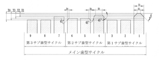
図1~3、12を参照し、本発明の硬質合金帯鋸刃であって、9つの鋸歯を1つのメインサイクルとし(9つの鋸歯は1つのメイン鋸歯グループを形成する)、3つずつの鋸歯を1つのサブサイクルとし(3つの鋸歯は1つのサブ鋸歯グループを形成する)、各サブサイクルには順に並ぶ1つの直歯ガイド歯、1つの左アサリ歯、1つの右アサリ歯が含まれる(図2において、Sはアサリなし直歯であり、Lは左向きアサリ歯であり、Rは右向きアサリ歯である)。9つの鋸歯には5段階の歯高さがある。、歯高さとは鋸歯の歯先高さを指し、高い順に、第1段階の高さ~第5段階の高さに分けられ、好ましくは、各段階の高さ段差が同じである(図3において、Y1~Y4は歯間の高さの差であり、各段階の高さ差はいずれも同じである)。9つの鋸歯には4種類の歯先形状がある。この4種類の歯先形状は、以下のとおりである。
第1種類、直歯で面取りがない
第2種類、直歯で両側に面取りがある
第3種類、アサリあり、外側に面取りがある
第4種類、アサリあり、面取りがない
With reference to FIGS. 1 to 3 and 12, in the hard alloy band saw blade of the present invention, nine saw teeth are used as one main cycle (nine saw teeth form one main saw tooth group), and three saw teeth are formed. Is one subcycle (three saw teeth form one sub-saw tooth group), and each subcycle contains one straight tooth guide tooth, one left tooth, and one right tooth in order (one right tooth). In FIG. 2, S is a straight tooth without a set, L is a left-facing tooth, and R is a right-facing tooth). The nine saw teeth have five levels of tooth height. The tooth height refers to the height of the tooth tip of the saw tooth, and is divided into the height of the first stage to the height of the fifth stage in descending order, and preferably the height step of each stage is the same (FIG. 3). In, Y1 to Y4 are differences in height between teeth, and the height difference in each step is the same). There are four types of tooth tip shapes in the nine saw teeth. These four types of tooth tip shapes are as follows.
1st type, straight teeth without chamfering 2nd type, straight teeth with chamfers on both sides 3rd type, with shavings, with chamfering on the outside 4th type, with shavings, no chamfering
メインサイクルにおいて、1番の歯は最も高い歯であり、歯先高さが第1段階であり、第2種類の歯先形状を有し、面取りされていない部分の幅X2が鋸刃厚さX1の25%である。 In the main cycle, the first tooth is the tallest tooth, the tooth tip height is the first stage, it has the second kind of tooth tip shape, and the width X2 of the non-chatomed part is the saw blade thickness. It is 25% of X1.
その後の2番の歯、3番の歯は第4種類の歯先であり、それらの高さが第5段階であり、且つ対称的に左右にアサリ振り出し加工が行われた。 Subsequent 2nd and 3rd teeth are the 4th kind of tooth tips, their height is the 5th stage, and the shaving processing is performed symmetrically to the left and right.
4番の歯は第2種類の直歯であり、1番の歯の高さより一段低く、高さが第2段階である。面取りされていない部分の幅X3が帯鋸刃厚さX1の66%である。 The fourth tooth is the second kind of straight tooth, which is one step lower than the height of the first tooth, and the height is the second step. The width X3 of the unchamfered portion is 66% of the band saw blade thickness X1.
5番の歯、6番の歯は第3種類の歯先であり、それぞれ左右にアサリ振り出し加工が行われ、歯先高さが第4段階であり、2番の歯、3番の歯より一段高い。一方側が面取りされ、その面取り幅X4がアサリ振出量Sの50%である。 The 5th and 6th teeth are the 3rd type of tooth tips, each of which is sewn out to the left and right, and the tooth tip height is the 4th stage, from the 2nd tooth and the 3rd tooth. One step higher. One side is chamfered, and the chamfer width X4 is 50% of the feedout amount S.
7番の歯は第1種類の直歯の歯型であり、歯先高さが第3段階である。
The 7th tooth is a
8番の歯、9番の歯は第1種類の歯先であり、それぞれ左右にアサリ振り出し加工が行われ、歯先高さが第5段階であり、アサリ振出量及び高さがいずれも2番の歯、3番の歯と同じである。 The 8th and 9th teeth are the first type of tooth tips, and the tooth tip is drawn out to the left and right respectively, the tooth tip height is the 5th stage, and the amount and height of the tooth tip are both 2. It is the same as the third tooth.
1番の歯、2番の歯、3番の歯は第1サブ鋸歯グループを構成し、4番の歯、5番の歯、6番の歯は第2サブ鋸歯グループを構成し、7番の歯、8番の歯、9番の歯は第3サブ鋸歯グループを構成する。なお、第1サブ鋸歯グループ、第2サブ鋸歯グループ及び第3サブ鋸歯グループの並び方法は自由に組み合わせることができ、切削数又はサイズ又は切削能力に影響を与えない。 The 1st tooth, the 2nd tooth, the 3rd tooth constitutes the 1st sub-sawtooth group, the 4th tooth, the 5th tooth, the 6th tooth constitutes the 2nd sub-sawtooth group, and the 7th tooth. The tooth No. 8, the tooth No. 8 and the tooth No. 9 constitute the third sub-sawtooth group. The arrangement method of the first sub-sawtooth group, the second sub-sawtooth group and the third sub-sawtooth group can be freely combined and does not affect the number or size of cutting or the cutting ability.
本発明の歯型は、硬質合金ヘッドが溶接される前に歯フライス加工(又は他の加工方式)によって成形された基材の歯型と必然的な関連性がなく、例えば、歯フライス加工によって形成された歯型サイクルは、7つの歯が1つのサイクルを形成し又は5つの歯が1つのサイクルを形成する可能性がある。従って、基材の歯先成形後の歯型サイクルが7つの歯であり、且つ歯先研削サイクルが本発明によって設計される場合、実際に鋸刃の歯型サイクルは64個の歯が1つのサイクルを形成するものである。歯フライス加工サイクルと歯研削サイクルとが合致しないため、歯フライス加工によって成形された同一の歯型において1番の研削歯の歯先が64個の歯ごとに現れる。 The tooth mold of the present invention is not necessarily related to the tooth mold of the substrate formed by tooth milling (or other processing method) before the cemented carbide head is welded, for example, by tooth milling. In the formed tooth pattern cycle, 7 teeth may form one cycle or 5 teeth may form one cycle. Therefore, when the tooth mold cycle after the tooth tip molding of the base material is 7 teeth and the tooth tip grinding cycle is designed by the present invention, the saw blade tooth mold cycle is actually one tooth of 64 teeth. It forms a cycle. Since the tooth milling cycle and the tooth grinding cycle do not match, the tip of the first grinding tooth appears every 64 teeth in the same tooth mold formed by the tooth milling.
本願の別の変更は逃げ角を従来の20度から25度に調整することである。1986年から、主に逃げ角が大きくなると切断中に振動が大きすぎることを懸念するため、硬質合金帯鋸刃の歯先の逃げ角は20度を用いてきた。しかし、本発明によって設計される歯型は、現場でインコネル718の切断を試みることにより、25度の逃げ角が大きすぎる振動を引き起こさないことを証明した。逃げ角増大の目的は切削力をさらに低減することである。 Another modification of the present application is to adjust the clearance angle from the conventional 20 degrees to 25 degrees. Since 1986, the clearance angle of the tooth tip of the cemented carbide band saw blade has been used to be 20 degrees, mainly because there is a concern that the vibration becomes too large during cutting when the clearance angle becomes large. However, the tooth molds designed by the present invention have proved by attempting to cut Inconel 718 in the field that a 25 degree clearance angle does not cause vibrations that are too large. The purpose of increasing the clearance angle is to further reduce the cutting force.
本願の主な目的は、できるだけ多くの切り屑を生じて総切削力を低減することである。該歯型を用いて切削する時、同じ切削効率の状況下で、各歯の平均切削力がより小さく、生じた切り屑が狭くて厚い。 The main purpose of the present application is to generate as much chips as possible to reduce the total cutting force. When cutting with the tooth mold, the average cutting force of each tooth is smaller and the generated chips are narrower and thicker under the same cutting efficiency situation.
本願の別の目的も米国特許US5832803に開示されている歯型とは異なり、それは現在のより大きくてより切削しにくい材料に対応できる。勿論、US5832803の製品は市場に20年ほど存在できることは、その成功した設計からであり、それは米国特許US5331871の更新バージョンの設計ではなく、別の理念である。 Another object of the present application is also different from the tooth profile disclosed in US patent US5832803, which can accommodate larger and more difficult-to-cut materials at present. Of course, the fact that the US5832803 product can exist on the market for about 20 years is due to its successful design, which is not the design of the updated version of the US patent US5331871, but another idea.
本発明の歯型設計の目的は、切削力を低減し、さらに切刃の張力損失を低減することである。これによって、切断の品質を向上させ且つ帯鋸刃の耐用年数を延長させる。 An object of the tooth mold design of the present invention is to reduce the cutting force and further reduce the tension loss of the cutting edge. This improves the quality of cutting and extends the service life of the band saw blade.
本願の帯鋸刃歯型と他の歯型との切削力の分析比較 Analytical comparison of cutting force between the band saw blade tooth mold of the present application and other tooth molds
切削力の低減に関するほとんどの歯型特許の明細書では、原理を分析せず、主にさまざまな形態の複数の切り屑を生じる歯の幾何学的形状に注目しており、また、性能評価を特許審査官に任せ、エンドユーザーがこれらの請求項を受けることを事実とする。 Most tooth mold patent specifications for reducing cutting force do not analyze the principle, but mainly focus on the geometry of the tooth that produces multiple chips of various forms, and also perform performance evaluation. It is the fact that the end user receives these claims, leaving it to the patent examiner.
以下では、さまざまな歯型がどのように切削力に影響を与えるかを原理的に分析する。先ず、切り屑厚さと切り屑の形成に必要な切削力との関係を理解する必要がある。2002年、ドイツのドレスデン(Dresden)で開催されたフレキシブル自動化とスマート製造国際会議では、M.Sarwar、H.Hellberg、A.R、Doraisingam及びM.Perssonは「帯鋸刃の断続的な切削動作のシミュレーション(Simulation of the Intermittent Cutting Action of a Bandsaw Blade)」をタイトルとする論文を提案した。該研究は、イギリス・ニューカッスル・ノーザンブリア大学の工学部で完了された。 In the following, we will analyze in principle how various tooth patterns affect the cutting force. First, it is necessary to understand the relationship between the chip thickness and the cutting force required to form the chips. At the 2002 International Conference on Flexible Automation and Smart Manufacturing held in Dresden, Germany, M.D. Sarwar, H. et al. Hellberg, A.M. R, Doraisingam and M.D. Persson proposed a paper entitled "Simulation of the Intermitted Cutting Action of a Bandsaw Blade". The study was completed at the Faculty of Engineering, Northumbria University, Newcastle, England.
該研究は本質的に切断時に生じる切削力と切り屑厚さとの関係を研究したものである。彼らは1つの単一歯切断試料を旋盤の回転治具に取り付ける。単一の歯台に取り付けられた計器は切削力及び送り力を測定した。該論文の1つの図は本出願の図4に示される。 The study essentially studies the relationship between the cutting force generated during cutting and the chip thickness. They attach one single tooth cutting sample to the rotating jig of a lathe. Instruments mounted on a single tooth stand measured cutting and feeding forces. One figure of the paper is shown in Figure 4 of this application.
本願の発明者は1991年から2006年までの15年間一緒に働いたHellberg氏とPersson氏の同僚である。この期間、「経験則」によって、切り屑厚さを2倍にすると、切削力が60%しか増加しないと考えられた。長年にわたって、すべてのタイプの材料に対する切断テストは、この理論を証明し、帯鋸刃はバイメタル及び硬質合金チップ帯鋸刃を含む。該研究結果及び試験結果に基づき、図5の切削力と切り屑厚さとの関係曲線をまとめた。 The inventor of the present application is a colleague of Mr. Hellberg and Mr. Persson who worked together for 15 years from 1991 to 2006. During this period, according to the "rule of thumb", it was considered that doubling the chip thickness would increase the cutting force by only 60%. Over the years, cutting tests on all types of materials have proved this theory, and band saw blades include bimetal and hard alloy tip band saw blades. Based on the research results and test results, the relationship curve between the cutting force and the chip thickness in FIG. 5 is summarized.
該図では、横軸の切り屑深さと縦軸の切削力は標準化された。標準切り屑厚さ値「1.0」は特定の材料を切断する時の帯鋸刃切断の歯あたりの推奨切削深さを表す。標準切削力「1.0」は、1mm幅の単一歯で、切削される特定の材料の1.0標準化切り屑厚さを切削するのに必要な力を表す(以下では単位切削力と称する)。 In the figure, the chip depth on the horizontal axis and the cutting force on the vertical axis are standardized. The standard chip thickness value "1.0" represents the recommended cutting depth per tooth for band saw blade cutting when cutting a specific material. The standard cutting force "1.0" represents the force required to cut the 1.0 standardized chip thickness of a specific material to be cut with a single tooth with a width of 1 mm (hereinafter referred to as the unit cutting force). Call).
図4のグラフを標準化した場合の図5の曲線を検証する。図5の曲線図は、切削される材料に関わらず、さまざまな歯型の相対的な切削力を比較することに用いられる。 The curve of FIG. 5 when the graph of FIG. 4 is standardized is verified. The curve diagram of FIG. 5 is used to compare the relative cutting forces of different tooth molds, regardless of the material being cut.
前人の歯型設計と本願の歯型との比較分析はインコネル718の切断を例とする。該分析は、同じ切削速度、同じ送り速度、同じ切り幅(2.6mm)、同じ材料及び同じピッチというパラメータに基づくものである。 The comparative analysis between the tooth pattern design of the former and the tooth pattern of the present application takes the cutting of Inconel 718 as an example. The analysis is based on the parameters of the same cutting speed, the same feed rate, the same cutting width (2.6 mm), the same material and the same pitch.
図6はフラット歯切削の模式図である。C1は生じた1番目の切り屑であり、切り屑厚さtc=1.0、F=1.0f/mm、fは1mmあたりの切り屑幅で表れる1つの単位切削力であり、Ft=(2.6)×F=2.6f、歯あたりの平均切削力は2.6fである。 FIG. 6 is a schematic diagram of flat tooth cutting. C1 is the first chip generated, chip thickness tc = 1.0, F = 1.0 f / mm, f is one unit cutting force expressed by the chip width per 1 mm, and Ft = (2.6) × F = 2.6f, and the average cutting force per tooth is 2.6f.
図7はバーコ(Bahco)3868 TSX、レノックス(Lenox)Tri Tech、ビチャムプ(Bichamp)CB MP等の三歯のアサリあり歯型の切削模式図である。C1~C3は生じた3枚の切り屑を示し、
Ft=((2)×(0.65)×(2.1)+(1.3)×(2.1))f
Ft=2.73+2.73=5.46f
歯あたりの平均切削力=総切削力/総歯数=5.46f/3=1.82f。
FIG. 7 is a schematic cutting diagram of a tooth mold with three teeth such as Bahco 3868 TSX, Lenox Tri Tech, and Bichamp CB MP. C1 to C3 indicate the three chips generated,
Ft = ((2) × (0.65) × (2.1) + (1.3) × (2.1)) f
Ft = 2.73 + 2.73 = 5.46f
Average cutting force per tooth = total cutting force / total number of teeth = 5.46f / 3 = 1.82f.
図8はバーコ(Bahco)3881 THQ、ビチャムプ(Bichamp)CB PRO等の六歯のアサリあり歯型の切削模式図である。C1~C7は生じた7枚の切り屑を示し、
Ft=(2.6)×(3.35)=9.1f
歯あたりの平均切削力=総切削力/歯数=9.1f/6=1.516f。
FIG. 8 is a schematic cutting diagram of a six-toothed tooth mold such as Bahco 3881 THQ and Bichamp CB PRO. C1 to C7 indicate the seven chips generated,
Ft = (2.6) x (3.35) = 9.1f
Average cutting force per tooth = total cutting force / number of teeth = 9.1f / 6 = 1.516f.
図9はレノックス(Lenox)Cast Masterの三歯のアサリなし歯型の切削模式図である。C1~C5は生じた5枚の切り屑を示し、
Ft=(2.6)×(2.1)=5.46f
歯あたりの平均切削力=総切削力/歯数=5.46f/3=1.82f。
FIG. 9 is a schematic cutting diagram of a three-toothed tooth mold of Lenox Cast Master. C1 to C5 indicate the five chips generated,
Ft = (2.6) x (2.1) = 5.46f
Average cutting force per tooth = total cutting force / number of teeth = 5.46f / 3 = 1.82f.
図10はWikus542のアサリなし歯型の切削模式図である。C1~C7は生じた7枚の切り屑を示し、
Ft=((1)×(2.56)+(2)×(0.45)×(2.56)+4×(0.35)×(2.1))f
=(2.56+2.304+2.24)f
Ft=7.104f
歯あたりの平均切削力=総切削力/歯数=7.104f/4=1.776f。
FIG. 10 is a schematic cutting diagram of a tooth mold without lajonkairia lajonkairia of Wikus 542. C1 to C7 indicate the seven chips generated,
Ft = ((1) × (2.56) + (2) × (0.45) × (2.56) + 4 × (0.35) × (2.1)) f
= (2.56 + 2.304 + 2.24) f
Ft = 7.104f
Average cutting force per tooth = total cutting force / number of teeth = 7.104f / 4 = 1.776f.
図11は標準のアサリなし切り屑3枚型歯型の切削模式図である。C1~C3は生じた3枚の切り屑を示し、
Ft=(2.6)×(1.6)=4.16f
歯あたりの平均切削力=総切削力/歯数=4.16f/2=2.08f。
FIG. 11 is a schematic cutting diagram of a standard three-sheet chip type tooth mold without lajonkairia lajonkairia. C1 to C3 indicate the three chips generated,
Ft = (2.6) x (1.6) = 4.16f
Average cutting force per tooth = total cutting force / number of teeth = 4.16f / 2 = 2.08f.
図12は本願の歯型の切削模式図である。C1~C11は生じた11枚の切り屑を示し、
切り屑厚さはtcであり、
切り屑(3,4,5,6,7,8,9)tc=9、F=4.5f
切り屑(2,10)tc=6、F=3.35f
切り屑(1,11)tc=3、F=2.1f
Ft=((2.1)×(4.5)+(2)×(0.25)×(2.1)+(2)×(0.25)×(3.35))f
=(9.45+1.05+1.675)f
Ft=12.175f
歯あたりの平均切削力=総切削力/歯数=12.175f/9=1.352f。
FIG. 12 is a schematic cutting diagram of the tooth mold of the present application. C1 to C11 indicate the 11 chips generated,
The chip thickness is ct,
Chips (3,4,5,6,7,8,9) tk = 9, F = 4.5f
Chips (2,10) tk = 6, F = 3.35f
Chips (1,11) tk = 3, F = 2.1f
Ft = ((2.1) x (4.5) + (2) x (0.25) x (2.1) + (2) x (0.25) x (3.35)) f
= (9.45 + 1.05 + 1.675) f
Ft = 12.175f
Average cutting force per tooth = total cutting force / number of teeth = 12.175f / 9 = 1.352f.
最後に、さまざまな歯型の歯あたりの平均切削力を比較する。その結果は刃物の最も低い切削力に基づくものであり、7つの歯型の歯あたりの平均切削力は低い順に表1に示される。 Finally, we compare the average cutting forces per tooth of different tooth types. The results are based on the lowest cutting force of the blade, and the average cutting force per tooth of the seven tooth molds is shown in Table 1 in ascending order.

明らかに、本願の歯型の切削力が最も低い。なお、切削力が線形的で、切り屑厚さが切削力の2倍であると仮定する場合、すべての歯が同じ2.6倍の単位切削力を有する。また、本願の歯型の最上部隙間角を25度まで増加することを考慮すると、実際には、切削力はより小さくなる。 Obviously, the cutting force of the tooth mold of the present application is the lowest. Assuming that the cutting force is linear and the chip thickness is twice the cutting force, all teeth have the same unit cutting force of 2.6 times. Further, considering that the uppermost clearance angle of the tooth mold of the present application is increased to 25 degrees, the cutting force is actually smaller.
米国特許出願公開US2005/257660A1に開示された書類において、その時にバーコ(Bahco)ツールのパートタイム従業員であった本願の発明者は、三歯のアサリあり歯型を2つ提案した。基本的に、該出願はBahco 3881 THQと類似する歯型であり、薄い切り屑を生成するためのアサリあり面取り歯を除き、より小さいアサリ振出量を有する面取りされていない平歯を使用し、該出願の歯型が3868 TSPと表記される。標準Bahco 3868 TSX及び3881 THQに提案された歯型に基づいてサンプルを設計し、耐摩耗テストを行った。テストワークは140mm角の304 SSである。各鋸刃の初期切削力が予想されたものと合致し、TSX鋸刃が最大の力を有し、THQ及びTSPの力が80%低減する。興味深いことに、歯先切削力を比較する新しい方法には類似する比較がある。TSX歯型は55枚を切断し、THQは90枚を切断し、TSPは27枚だけの切削を完了する。TSP歯型は失敗したと考えられ、該プロジェクトはキャンセルされ、特許は拒絶された。その時、理解されていないことは、複数のアサリ振出量の組み合わせの場合、硬質合金鋸刃は必ず失敗するが、バイメタルにこの問題がないことである。根本的な理由は、鋸刃の逃げ角の差であり、通常、硬質合金鋸刃は20度であるが、バイメタル鋸刃は30度である。該角度は逆に歯先のねじれ角に影響を与え、メイン逃げ角が小さいほど、ねじれ角が小さくなる。ねじれ角が小さいほど、歯先がエッジ摩耗しやすくなり、それにより、より高い横方向力及びより低い横方向切削能力をもたらし、これは、TSP鋸刃が低いアサリ振出量を設定するため失敗する理由である。 In a document disclosed in US Patent Application Publication US2005 / 257660A1, the inventor of the present application, who was a part-time employee of Bahco Tools at the time, proposed two tooth patterns with three-toothed teeth. Basically, the application is a tooth profile similar to Bahco 3881 THQ, using unchamfered flat teeth with a smaller amount of scuffing, except for chamfered chamfered teeth to produce thin chips. The tooth pattern of the application is referred to as 3868 TSP. Samples were designed and wear resistant tested based on the tooth molds proposed in the standard Bahco 3868 TSX and 3881 THQ. The test work is a 140 mm square 304 SS. The initial cutting force of each saw blade matches what was expected, the TSX saw blade has the maximum force, and the THQ and TSP forces are reduced by 80%. Interestingly, there are similar comparisons in the new way of comparing tooth tip cutting forces. The TSX tooth mold cuts 55 pieces, THQ cuts 90 pieces, and TSP cuts only 27 pieces. The TSP tooth pattern was considered unsuccessful, the project was canceled and the patent was rejected. At that time, what is not understood is that in the case of a combination of multiple feedout amounts, the carbide saw blade always fails, but the bimetal does not have this problem. The fundamental reason is the difference in the clearance angle of the saw blade, which is usually 20 degrees for a hard alloy saw blade, but 30 degrees for a bimetal saw blade. On the contrary, the angle affects the helix angle of the tooth tip, and the smaller the main clearance angle, the smaller the helix angle. The smaller the twist angle, the more prone to edge wear of the tooth tip, which results in higher lateral force and lower lateral cutting ability, which fails because the TSP saw blade sets a lower shear feed rate. That's the reason.
特殊なアサリ振出方式でアサリ振り出し加工が行われた、正常なアサリ振出量を保つ硬質合金鋸刃は、歯先をできるだけねじることで、十分なねじれ角度を達成し、切断が早すぎることを防止する。皮肉なことに、最初に面取り歯の概念のみを使用するのは、主にその時にアサリ振り出し装置が複数の段階のアサリ振出量を形成できないからである。さらなる証拠として、市場には複数のアサリ振出量段階の硬質合金鋸刃がなく、そして、バイメタル帯鋸刃の高低歯はマルチ段階のアサリ歯である。 The hard alloy saw blade that maintains the normal amount of shavings, which has been sewn out by a special shaving method, achieves a sufficient twisting angle by twisting the tip of the tooth as much as possible and prevents cutting too early. do. Ironically, the first use of the concept of chamfered teeth is primarily due to the inability of the lajonkairia lajonkai to form multiple stages of lajonkairia lajonkairia at that time. As further evidence, there are no hard alloy saw blades on the market with multiple feedout stages, and the high and low teeth of bimetal band saw blades are multi-stage lajonkai teeth.
図13では、ねじれ角に対する逃げ角とアサリ振出量の影響が示される。 FIG. 13 shows the effects of the clearance angle and the amount of shearing on the helix angle.
試験テスト
中国の1つの大手クロムニッケル鉄合金メーカーで試験を行った。目標はサイズが550ミリメートル(21インチ)を超える大型のInconel 718鍛造品の切断を完了することである。この前に米国のメーカーが製造したTriple Set型の硬質合金ブレードで切断することを試み、3つの鋸刃を用いても該タスクを完了できなかった。ビチャムプ(Bichamp)のCB PRO帯鋸刃で行われたテストでは、16時間以内に1回の切断が行われたが、切断された底部三分の一の箇所で切断が傾いた。
Test test Tested by one of the leading manufacturers of chromium nickel iron alloys in China. The goal is to complete the cutting of large Inconel 718 forgings that are over 550 millimeters (21 inches) in size. Prior to this, an attempt was made to cut with a Triple Set type carbide blade manufactured by an American manufacturer, and the task could not be completed even with three saw blades. In a test performed with Bichamp's CB PRO band saw blade, one cut was made within 16 hours, but the cut was tilted at the bottom third of the cut.
本願の帯鋸刃を用いる場合、初めての切断では、8時間以内にワーク全体の切断加工をうまく完了し、切断が傾くなどの故障がない。帯鋸刃作業者は非常に注意深く慎重であることを考えると、切断時間はそれほど長くない。その後、複数の同様な製品を用いてテストを行った結果、本願の切断効率、切断効果及び切断耐用年数は、他の製品に比べて、いずれも顕著に改良された。 When the band saw blade of the present application is used, in the first cutting, the cutting process of the entire work is successfully completed within 8 hours, and there is no failure such as tilting of the cutting. The cutting time is not very long, considering that the band saw blade worker is very careful and careful. After that, as a result of testing using a plurality of similar products, the cutting efficiency, cutting effect and cutting service life of the present application were all significantly improved as compared with other products.
以上、図面を参照しながら本発明の実施例を説明し、矛盾しない限り、本発明の実施例及び実施例の特徴は相互に組み合わせることができる。本発明は上記具体的な実施形態に制限されず、上記具体的な実施形態は例示的なものに過ぎず、限定的なものではなく、当業者は本発明の示唆下で、本発明の趣旨及び特許請求の範囲の保護範囲から逸脱することなく、多くの形態をとることができ、これらはいずれも本発明の保護範囲内に属する。 Examples of the present invention will be described above with reference to the drawings, and as long as there is no contradiction, the examples of the present invention and the features of the examples can be combined with each other. The present invention is not limited to the above-mentioned specific embodiment, and the above-mentioned specific embodiment is merely exemplary and not limiting. And many forms can be taken without departing from the scope of the claims, all of which fall within the scope of the invention.
Claims (10)
前記第1サブ鋸歯グループの第1鋸歯は第1高さを有し、その両側にいずれも面取りが設けられ、前記第2サブ鋸歯グループの第1鋸歯は第2高さを有し、その両側にいずれも面取りが設けられ、且つ最上部平面幅が前記第1サブ鋸歯グループの第1鋸歯の最上部平面幅より大きく、前記第3サブ鋸歯グループの第1鋸歯は第3高さを有し、且つ最上部平面幅が前記第2サブ鋸歯グループの第1鋸歯の最上部平面幅より大きく、
前記第1サブ鋸歯グループの第2鋸歯、第3鋸歯と前記第3サブ鋸歯グループの第2鋸歯、第3鋸歯は、同じ第5高さ及びアサリ振出量を有し、前記第2サブ鋸歯グループの第2鋸歯、第3鋸歯は第4高さを有し、且つ第2サブ鋸歯グループの第2鋸歯、第3鋸歯の外側に面取りが設けられ、
前記第1高さ、第2高さ、第3高さ、第4高さ及び第5高さは順に逓減する、ことを特徴とする帯鋸刃。 A band saw blade including saw blades in the saw blade body and the saw blade body, and nine saw blades arranged in order form one main saw blade group, and each main saw blade group is a first sub-saw blade group and a second sub-saw blade group. And a third sub-saw blade group, each sub-saw blade group includes a first saw blade, a second saw blade and a third saw tooth which are arranged in order, the first saw blade is a straight tooth, and the second saw tooth and the third saw tooth. The saw blades are the left and right saw blades, respectively.
The first sawtooth of the first sub-sawtooth group has a first height and chamfers are provided on both sides thereof, and the first sawtooth of the second sub-sawtooth group has a second height and both sides thereof. The top plane width is larger than the top plane width of the first sawtooth of the first sub-sawtooth group, and the first sawtooth of the third sub-sawtooth group has a third height. And the uppermost plane width is larger than the uppermost plane width of the first sawtooth of the second sub-sawtooth group.
The second sawtooth and the third sawtooth of the first sub-sawtooth group and the second sawtooth and the third sawtooth of the third sub-sawtooth group have the same fifth height and chamfering amount , and the second sub-sawtooth group. The second saw tooth and the third saw tooth have a fourth height, and chamfers are provided on the outside of the second saw tooth and the third saw tooth of the second sub saw tooth group.
A band saw blade characterized in that the first height, the second height, the third height, the fourth height, and the fifth height gradually decrease in order.
Applications Claiming Priority (1)
| Application Number | Priority Date | Filing Date | Title |
|---|---|---|---|
| PCT/CN2019/093228 WO2020258141A1 (en) | 2019-06-27 | 2019-06-27 | Band saw blade |
Publications (2)
| Publication Number | Publication Date |
|---|---|
| JP2021531984A JP2021531984A (en) | 2021-11-25 |
| JP7091483B2 true JP7091483B2 (en) | 2022-06-27 |
Family
ID=74060425
Family Applications (1)
| Application Number | Title | Priority Date | Filing Date |
|---|---|---|---|
| JP2020566952A Active JP7091483B2 (en) | 2019-06-27 | 2019-06-27 | Band saw blade |
Country Status (4)
| Country | Link |
|---|---|
| US (1) | US11376679B2 (en) |
| EP (1) | EP3848141B1 (en) |
| JP (1) | JP7091483B2 (en) |
| WO (1) | WO2020258141A1 (en) |
Citations (3)
| Publication number | Priority date | Publication date | Assignee | Title |
|---|---|---|---|---|
| JP2003340643A (en) | 2002-05-22 | 2003-12-02 | Amada Co Ltd | Band saw blade |
| JP2005305639A (en) | 2004-04-16 | 2005-11-04 | Kapman Ab | Band saw tooth and method of manufacturing band saw tooth |
| JP2012232409A (en) | 2011-05-06 | 2012-11-29 | Wikus-Saegenfabrik Wilhelm H Kullmann Gmbh & Co Kg | Saw blade for sawing hollow profile and profile |
Family Cites Families (17)
| Publication number | Priority date | Publication date | Assignee | Title |
|---|---|---|---|---|
| JPH0724973B2 (en) * | 1985-04-03 | 1995-03-22 | 株式会社アマダ | Saw blade |
| CA1277573C (en) | 1985-04-03 | 1990-12-11 | Sumio Yoshida | Saw blade |
| US4784033A (en) | 1986-01-22 | 1988-11-15 | Milford Products Corporation | Triple chip ground carbide tip bandsaw blade with ductile filler |
| US5331876A (en) * | 1992-07-30 | 1994-07-26 | Sandvik Ab | Saw blade for cutting metal |
| DE9321337U1 (en) | 1992-07-30 | 1997-06-26 | Sandvik Ab | Saw blade for metal cutting |
| US5331871A (en) | 1992-12-16 | 1994-07-26 | Carrier Corporation | Method of turning grooves |
| US5832803A (en) | 1996-08-21 | 1998-11-10 | Sandvik Ab | Tooth structure of a bandsaw blade |
| US6119571A (en) | 1998-04-10 | 2000-09-19 | Sandvik Aktiebolag | Sawblade having unequal spacing between identical tooth groups |
| ATE238123T1 (en) | 1999-08-17 | 2003-05-15 | Handschuh & Scheider Gmbh | SAW BLADE WITH GROUPS OF TEETH OF DIFFERENT WIDTHS OR HEIGHTS |
| DE19963396C2 (en) * | 1999-12-28 | 2003-12-04 | Kullmann Wikus Saegenfab | Saw blade with a basic body and unrestricted teeth |
| DE60318178T2 (en) | 2003-04-25 | 2008-12-04 | Kapman Ab | band saw blade |
| EP1586401A1 (en) | 2004-04-16 | 2005-10-19 | Kapman AB | Bandsaw blade and method of manufacturing bandsaw blade |
| JP5600473B2 (en) * | 2009-05-12 | 2014-10-01 | 株式会社アマダ | Band saw blade |
| DE102009027896B4 (en) | 2009-07-21 | 2011-09-22 | WIKUS-Sägenfabrik Wilhelm H. Kullmann GmbH & Co. KG | Saw blade with teeth with a chip forming element |
| DE102011053720B4 (en) | 2011-09-16 | 2015-12-24 | WIKUS-Sägenfabrik Wilhelm H. Kullmann GmbH & Co. KG | Saw blade with power teeth and surface teeth |
| JP5903345B2 (en) | 2012-07-17 | 2016-04-13 | 株式会社アマダホールディングス | Optimum arrangement method of each tooth of saw blade and saw blade |
| US10926343B2 (en) | 2016-04-19 | 2021-02-23 | The M. K. Morse Company | Ground set saw blade |
-
2019
- 2019-06-27 US US17/252,625 patent/US11376679B2/en active Active
- 2019-06-27 JP JP2020566952A patent/JP7091483B2/en active Active
- 2019-06-27 EP EP19935404.4A patent/EP3848141B1/en active Active
- 2019-06-27 WO PCT/CN2019/093228 patent/WO2020258141A1/en unknown
Patent Citations (3)
| Publication number | Priority date | Publication date | Assignee | Title |
|---|---|---|---|---|
| JP2003340643A (en) | 2002-05-22 | 2003-12-02 | Amada Co Ltd | Band saw blade |
| JP2005305639A (en) | 2004-04-16 | 2005-11-04 | Kapman Ab | Band saw tooth and method of manufacturing band saw tooth |
| JP2012232409A (en) | 2011-05-06 | 2012-11-29 | Wikus-Saegenfabrik Wilhelm H Kullmann Gmbh & Co Kg | Saw blade for sawing hollow profile and profile |
Also Published As
| Publication number | Publication date |
|---|---|
| JP2021531984A (en) | 2021-11-25 |
| WO2020258141A1 (en) | 2020-12-30 |
| EP3848141A1 (en) | 2021-07-14 |
| EP3848141A4 (en) | 2021-11-03 |
| EP3848141B1 (en) | 2023-03-08 |
| US20220105580A1 (en) | 2022-04-07 |
| US11376679B2 (en) | 2022-07-05 |
Similar Documents
| Publication | Publication Date | Title |
|---|---|---|
| JP5108106B2 (en) | Throw-away cutting rotary tool | |
| US20050257660A1 (en) | Bandsaw blade and method of manufacturing a bandsaw blade | |
| CN110202209B (en) | Band saw blade | |
| US8689442B2 (en) | Method for the fabrication of integrally bladed rotors | |
| US9038512B2 (en) | Method for manufacturing bandsaw blade, and bandsaw blade | |
| US20150097305A1 (en) | Milling method for the manufacture of dental prostheses | |
| JP4704495B2 (en) | Turbine blade connecting groove cutting method and Christmas cutter used therefor | |
| JP2002505626A5 (en) | ||
| JP2004338083A (en) | Band saw blade | |
| JP2002505626A (en) | Improved band saw | |
| US20220126383A1 (en) | Saw blade and system and method for manufacturing a saw blade | |
| JP7091483B2 (en) | Band saw blade | |
| CN109311107B (en) | Band saw blade and manufacturing method thereof | |
| CN110480095B (en) | Band saw blade | |
| JP2012171028A (en) | Square end mill | |
| JPWO2010023760A1 (en) | Throw-away cutting rotary tool | |
| CN218311059U (en) | Cyclone milling cutter for processing car crankshaft connecting rod neck | |
| JP6315867B1 (en) | Circular saw for metal cutting | |
| JP2012091259A (en) | End mill | |
| JP6527897B2 (en) | Hard tip band saw blade | |
| EP1586401A1 (en) | Bandsaw blade and method of manufacturing bandsaw blade | |
| CN220497947U (en) | Band saw | |
| EP3624977A1 (en) | Saw blade and method of manufacturing the same | |
| CN214867530U (en) | Automatic correction saw blade milling cutter for cutting deep and narrow grooves | |
| CN117139732A (en) | Band saw blade |
Legal Events
| Date | Code | Title | Description |
|---|---|---|---|
| A621 | Written request for application examination |
Free format text: JAPANESE INTERMEDIATE CODE: A621 Effective date: 20201125 |
|
| A131 | Notification of reasons for refusal |
Free format text: JAPANESE INTERMEDIATE CODE: A131 Effective date: 20211214 |
|
| A521 | Request for written amendment filed |
Free format text: JAPANESE INTERMEDIATE CODE: A523 Effective date: 20220308 |
|
| TRDD | Decision of grant or rejection written | ||
| A01 | Written decision to grant a patent or to grant a registration (utility model) |
Free format text: JAPANESE INTERMEDIATE CODE: A01 Effective date: 20220607 |
|
| A61 | First payment of annual fees (during grant procedure) |
Free format text: JAPANESE INTERMEDIATE CODE: A61 Effective date: 20220615 |
|
| R150 | Certificate of patent or registration of utility model |
Ref document number: 7091483 Country of ref document: JP Free format text: JAPANESE INTERMEDIATE CODE: R150 |