JP7091068B2 - Electronics - Google Patents

Electronics Download PDF

Info

Publication number
JP7091068B2
JP7091068B2 JP2017251259A JP2017251259A JP7091068B2 JP 7091068 B2 JP7091068 B2 JP 7091068B2 JP 2017251259 A JP2017251259 A JP 2017251259A JP 2017251259 A JP2017251259 A JP 2017251259A JP 7091068 B2 JP7091068 B2 JP 7091068B2
Authority
JP
Japan
Prior art keywords
image
output
target image
connection
control unit
Prior art date
Legal status (The legal status is an assumption and is not a legal conclusion. Google has not performed a legal analysis and makes no representation as to the accuracy of the status listed.)
Active
Application number
JP2017251259A
Other languages
Japanese (ja)
Other versions
JP2019118029A (en
JP2019118029A5 (en
Inventor
智昭 ▲高▼橋
Current Assignee (The listed assignees may be inaccurate. Google has not performed a legal analysis and makes no representation or warranty as to the accuracy of the list.)
Canon Inc
Original Assignee
Canon Inc
Priority date (The priority date is an assumption and is not a legal conclusion. Google has not performed a legal analysis and makes no representation as to the accuracy of the date listed.)
Filing date
Publication date
Priority to JP2017251259A priority Critical patent/JP7091068B2/en
Application filed by Canon Inc filed Critical Canon Inc
Priority to BR102018076873-5A priority patent/BR102018076873A2/en
Priority to KR1020180166846A priority patent/KR20190079536A/en
Priority to EP18215099.5A priority patent/EP3522000B1/en
Priority to US16/228,999 priority patent/US10972674B2/en
Priority to CN201811574812.1A priority patent/CN110049231B/en
Priority to CN201811574883.1A priority patent/CN110049258B/en
Priority to EP18215098.7A priority patent/EP3506078B1/en
Priority to KR1020180166847A priority patent/KR20190079537A/en
Priority to US16/228,970 priority patent/US10986280B2/en
Publication of JP2019118029A publication Critical patent/JP2019118029A/en
Priority to US16/837,246 priority patent/US11050943B2/en
Publication of JP2019118029A5 publication Critical patent/JP2019118029A5/ja
Application granted granted Critical
Publication of JP7091068B2 publication Critical patent/JP7091068B2/en
Active legal-status Critical Current
Anticipated expiration legal-status Critical

Links

Images

Description

本発明は、外部機器に画像を出力して表示することのできる電子機器に関する。 The present invention relates to an electronic device capable of outputting and displaying an image on an external device.

撮影された画像から輝度の度数分布を示すヒストグラム情報(輝度ヒストグラム)を取得して、画像とヒストグラム情報を外部機器(液晶モニターなどの表示装置)に出力して表示する電子機器がある。ユーザーは、ヒストグラム情報を参照することで、画像の露出が適正であったか否か、撮影条件が適切であったか否か、等を判断できる。 There is an electronic device that acquires histogram information (brightness histogram) indicating the frequency distribution of brightness from a captured image and outputs the image and histogram information to an external device (display device such as a liquid crystal monitor) for display. By referring to the histogram information, the user can determine whether or not the exposure of the image is appropriate, whether or not the shooting conditions are appropriate, and the like.

外部機器への画像の出力方法として、画像をダイナミックレンジの広いHDR画像に変換する変換処理を行い、HDR画像を外部機器に出力する方法(HDR映像出力)がある。変換処理が行われるため、HDR画像から取得されるヒストグラム情報は、変換処理前の画像から取得されるヒストグラム情報と異なる。なお、HDRとは、High Dynamic Range(ハイダイナミックレンジ)のことであり、SDR(スタンダードダイナミックレンジ)よりも広いダイナミックレンジのことである。 As a method of outputting an image to an external device, there is a method of performing a conversion process of converting the image into an HDR image having a wide dynamic range and outputting the HDR image to the external device (HDR video output). Since the conversion process is performed, the histogram information acquired from the HDR image is different from the histogram information acquired from the image before the conversion process. The HDR is a High Dynamic Range (high dynamic range), which is a wider dynamic range than the SDR (standard dynamic range).

特許文献1には、画像処理前のヒストグラム情報に近づける補正を画像処理後のヒストグラム情報に施すことで、撮影時の露光条件に近いヒストグラム情報を得る技術が開示されている。 Patent Document 1 discloses a technique for obtaining histogram information close to the exposure conditions at the time of shooting by applying a correction to the histogram information after image processing to bring it closer to the histogram information before image processing.

特開2006-33089号公報Japanese Unexamined Patent Publication No. 2006-33089

同一の元画像から生成された、階調分解能や色域がそれぞれ異なる画像を表示する場合がある。例えば、デジタルカメラの背面モニタではRAW画像から生成したSDR画像を表示し、デジタルカメラに接続された外部モニタには同一のRAW画像から生成されたHDR画像を表示する場合などである。 Images generated from the same original image with different gradation resolutions and color gamuts may be displayed. For example, the rear monitor of the digital camera may display the SDR image generated from the RAW image, and the external monitor connected to the digital camera may display the HDR image generated from the same RAW image.

この場合に、SDR画像から取得したヒストグラム情報を、HDR画像と共に外部モニタに表示する場合を考える。この場合には、例えば、ヒストグラム情報からは明るい部分の階調が失われていると判断できるのに対し、HDR画像からは明るい部分の階調が残っていると判断できるといった不一致が起こり、ユーザーに違和感を与える可能性がある。 In this case, consider a case where the histogram information acquired from the SDR image is displayed on an external monitor together with the HDR image. In this case, for example, it can be determined from the histogram information that the gradation of the bright part is lost, but from the HDR image, it can be determined that the gradation of the bright part remains. May give a sense of discomfort.

次に、HDR画像からヒストグラム情報を取得し、取得したヒストグラム情報をHDR画像と共に外部モニタに表示する場合を考える。この場合には、例えば、SDR画像では明るい部分の階調に余裕がないにもかかわらず、ユーザーが、ヒストグラム情報から明るい部分の階調に余裕があると判断し、デジタルカメラの露出を上げる操作を行うことがある。その結果、明るい部分の階調が失われ、意図せぬ露出の画像が撮影される可能性がある。 Next, consider a case where histogram information is acquired from the HDR image and the acquired histogram information is displayed on an external monitor together with the HDR image. In this case, for example, although there is no margin in the gradation of the bright portion in the SDR image, the user determines from the histogram information that there is a margin in the gradation of the bright portion, and increases the exposure of the digital camera. May be done. As a result, the gradation of the bright part is lost, and an image with unintended exposure may be taken.

特許文献1のヒストグラムの補正を行っても、上述の課題は解決されない。また、ヒストグラム以外にも、輝度、階調、色味の少なくとも1つに関する情報表示にも同様の課題がある。すなわち、同一の元画像から生成された階調分解能や色域がそれぞれ異なる画像を表示する場合、輝度、階調、色味の少なくとも1つに関する情報表示によって、ユーザ
ーの違和感や誤解を招き、不適切な操作や撮影が行われる可能性がある。
Even if the histogram of Patent Document 1 is corrected, the above-mentioned problem is not solved. In addition to the histogram, there is a similar problem in displaying information regarding at least one of luminance, gradation, and tint. That is, when displaying images having different gradation resolutions and color gamuts generated from the same original image, displaying information on at least one of luminance, gradation, and tint causes discomfort and misunderstanding of the user, which is not possible. Appropriate operation and shooting may be performed.

本発明は、輝度、階調、色味の少なくとも1つに関する情報表示によるユーザーの誤解を抑制できる技術を提供することを目的とする。 An object of the present invention is to provide a technique capable of suppressing a user's misunderstanding by displaying information on at least one of luminance, gradation, and tint.

本発明の電子機器は、外部機器と接続する接続手段と、表示手段と、前記表示手段に対象画像を表示する際に、所定の画面において、前記対象画像を第1階調分解能で表示するとともに、前記対象画像の輝度、階調、色味の少なくとも1つに関する情報表示アイテムを表示し、前記対象画像を前記接続手段から出力する際に、前記対象画像の前記情報表示アイテムを出力することなく、前記対象画像を前記第1階調分解能よりも高い第2階調分解能で出力するように制御する制御手段と、を有することを特徴とする。 The electronic device of the present invention displays the target image with a first gradation resolution on a predetermined screen when the target image is displayed on the connection means, the display means, and the display means connected to the external device. When displaying an information display item relating to at least one of the brightness, gradation, and tint of the target image and outputting the target image from the connection means, the information display item of the target image is not output. It is characterized by having a control means for controlling the target image to be output with a second gradation resolution higher than that of the first gradation resolution.

本発明によれば、輝度、階調、色味の少なくとも1つに関する情報表示によるユーザーの誤解を抑制できる。 According to the present invention, it is possible to suppress a user's misunderstanding due to information display regarding at least one of luminance, gradation, and tint.

本実施形態に係るデジタルカメラの外観図である。It is an external view of the digital camera which concerns on this embodiment. 本実施形態に係るデジタルカメラの構成例を示すブロック図である。It is a block diagram which shows the structural example of the digital camera which concerns on this embodiment. 本実施形態に係るデジタルカメラと外部機器との接続を表す図である。It is a figure which shows the connection between the digital camera which concerns on this embodiment, and an external device. 本実施形態に係るデジタルカメラのフローチャートである。It is a flowchart of the digital camera which concerns on this embodiment. 本実施形態に係るデジタルカメラのフローチャートである。It is a flowchart of the digital camera which concerns on this embodiment. 本実施形態に係るデジタルカメラのフローチャートである。It is a flowchart of the digital camera which concerns on this embodiment. 本実施形態に係るデジタルカメラのフローチャートである。It is a flowchart of the digital camera which concerns on this embodiment. 本実施形態に係るデジタルカメラのフローチャートである。It is a flowchart of the digital camera which concerns on this embodiment. 本実施形態に係るデジタルカメラのフローチャートである。It is a flowchart of the digital camera which concerns on this embodiment. 本実施形態に係るデジタルカメラ/外部機器の画面例である。It is a screen example of the digital camera / external device which concerns on this embodiment. 本実施形態に係るデジタルカメラ/外部機器の画面例である。It is a screen example of the digital camera / external device which concerns on this embodiment. 本実施形態に係るデジタルカメラ/外部機器の画面例である。It is a screen example of the digital camera / external device which concerns on this embodiment. 本実施形態に係るデジタルカメラ/外部機器の画面例である。It is a screen example of the digital camera / external device which concerns on this embodiment. 本実施形態に係るデジタルカメラのフローチャートである。It is a flowchart of the digital camera which concerns on this embodiment. 本実施形態に係るデジタルカメラ/外部機器の画面例である。It is a screen example of the digital camera / external device which concerns on this embodiment. 本実施形態に係るデジタルカメラのフローチャートである。It is a flowchart of the digital camera which concerns on this embodiment. 本実施形態に係るデジタルカメラのフローチャートである。It is a flowchart of the digital camera which concerns on this embodiment. 本実施形態に係るデジタルカメラ/外部機器の画面例である。It is a screen example of the digital camera / external device which concerns on this embodiment.

<構成>
以下、図面を参照して本発明の好適な実施形態を説明する。図1(A),1(B)に、本発明を適用可能な装置の一例としてのデジタルカメラ100の外観図を示す。図1(A)はデジタルカメラ100の前面斜視図であり、図1(B)はデジタルカメラ100の背面斜視図である。
<Structure>
Hereinafter, preferred embodiments of the present invention will be described with reference to the drawings. FIGS. 1 (A) and 1 (B) show external views of a digital camera 100 as an example of a device to which the present invention can be applied. 1A is a front perspective view of the digital camera 100, and FIG. 1B is a rear perspective view of the digital camera 100.

表示部28は、デジタルカメラ100の背面に設けられた表示部であり、画像や各種情報を表示する。ファインダー外表示部43は、デジタルカメラ100の上面に設けられた表示部であり、シャッター速度や絞りをはじめとするデジタルカメラ100の様々な設定値を表示する。端子カバー40は、デジタルカメラ100を外部機器に接続する接続ケーブル等のコネクタを保護するカバーである。コネクタには、USBケーブルの接続端子(不図示)と、HDMI(登録商標)出力端子である出力I/F91(後述)が含まれる。
クイックリターンミラー12は、システム制御部50(後述)から指示されて、不図示のアクチュエータによりアップダウンされる。通信端子10は、デジタルカメラ100がレンズユニット150(後述;着脱可能)側と通信を行うための通信端子である。接眼ファインダー16は、フォーカシングスクリーン13(後述)を観察することで、レンズユニット150を通して得た被写体の光学像の焦点や構図の確認を行うための覗き込み型のファインダーである。蓋202は、記録媒体200(後述)を格納するスロットの蓋である。グリップ部90は、ユーザーがデジタルカメラ100を構えた際に右手で握りやすい形状とした保持部である。
The display unit 28 is a display unit provided on the back surface of the digital camera 100, and displays an image and various information. The out-of-finder display unit 43 is a display unit provided on the upper surface of the digital camera 100, and displays various set values of the digital camera 100 such as a shutter speed and an aperture. The terminal cover 40 is a cover that protects a connector such as a connection cable that connects the digital camera 100 to an external device. The connector includes a USB cable connection terminal (not shown) and an HDMI (registered trademark) output terminal, an output I / F91 (described later).
The quick return mirror 12 is instructed by the system control unit 50 (described later) and is moved up and down by an actuator (not shown). The communication terminal 10 is a communication terminal for the digital camera 100 to communicate with the lens unit 150 (described later; detachable) side. The eyepiece finder 16 is a peep-type finder for confirming the focus and composition of the optical image of the subject obtained through the lens unit 150 by observing the focusing screen 13 (described later). The lid 202 is a lid for a slot that stores the recording medium 200 (described later). The grip portion 90 is a holding portion having a shape that makes it easy for the user to hold the digital camera 100 with his / her right hand.

また、デジタルカメラ100は、モード切替スイッチ60、シャッターボタン61、メイン電子ダイヤル71、電源スイッチ72、サブ電子ダイヤル73、4方向キー74、SETボタン75、及び、LVボタン76を有する。デジタルカメラは00は、拡大ボタン77、縮小ボタン78、再生ボタン79、タッチパネル70a、AF(オートフォーカス)-ONボタン70b、クイック設定ボタン70c(Qボタン70c)、及び、アクティブ枠切替ボタン70dも有する。デジタルカメラ100は、メニューボタン70e、ファンクションボタン70f、及び、インフォボタン70gも有する。デジタルカメラ100は、他の操作部材を有していてもよい。各種操作部材については後述する。 Further, the digital camera 100 has a mode changeover switch 60, a shutter button 61, a main electronic dial 71, a power switch 72, a sub electronic dial 73, a four-way key 74, a SET button 75, and an LV button 76. The digital camera 00 also has an enlargement button 77, a reduction button 78, a play button 79, a touch panel 70a, an AF (autofocus) -ON button 70b, a quick setting button 70c (Q button 70c), and an active frame switching button 70d. .. The digital camera 100 also has a menu button 70e, a function button 70f, and an info button 70g. The digital camera 100 may have other operating members. Various operating members will be described later.

図2は、デジタルカメラ100の構成例を示すブロック図である。 FIG. 2 is a block diagram showing a configuration example of the digital camera 100.

レンズユニット150は、交換可能な撮影レンズを搭載するレンズユニットである。レンズ103は通常、複数枚のレンズから構成されるが、図2では簡略して一枚のレンズのみを示している。通信端子6は、レンズユニット150がデジタルカメラ100側と通信を行うための通信端子であり、通信端子10は、デジタルカメラ100がレンズユニット150側と通信を行うための通信端子である。レンズユニット150は、これら通信端子6,10を介してシステム制御部50と通信する。そして、レンズユニット150は、内部のレンズシステム制御回路4によって絞り駆動回路2を介して絞り1の制御を行う。また、レンズユニット150は、レンズシステム制御回路4によってAF駆動回路3を介してレンズ103の位置を変位させることで焦点を合わせる。 The lens unit 150 is a lens unit equipped with an interchangeable photographing lens. The lens 103 is usually composed of a plurality of lenses, but FIG. 2 simply shows only one lens. The communication terminal 6 is a communication terminal for the lens unit 150 to communicate with the digital camera 100 side, and the communication terminal 10 is a communication terminal for the digital camera 100 to communicate with the lens unit 150 side. The lens unit 150 communicates with the system control unit 50 via these communication terminals 6 and 10. Then, the lens unit 150 controls the diaphragm 1 via the diaphragm drive circuit 2 by the internal lens system control circuit 4. Further, the lens unit 150 focuses by shifting the position of the lens 103 via the AF drive circuit 3 by the lens system control circuit 4.

AE(自動露出)センサー17は、レンズユニット150を通した被写体(被写体光)の輝度を測光する。 The AE (automatic exposure) sensor 17 measures the brightness of the subject (subject light) that has passed through the lens unit 150.

焦点検出部11は、システム制御部50にデフォーカス量情報を出力する。システム制御部50は、デフォーカス量情報に基づいてレンズユニット150を制御し、位相差AFを行う。 The focus detection unit 11 outputs defocus amount information to the system control unit 50. The system control unit 50 controls the lens unit 150 based on the defocus amount information, and performs phase difference AF.

クイックリターンミラー12(ミラー12)は、露光、ライブビュー撮影、動画撮影、等の際にシステム制御部50から指示されて、不図示のアクチュエータによりアップダウンされる。ミラー12は、レンズ103から入射した光束をファインダー16側と撮像部22側とに切り替えるためのミラーである。ミラー12は、通常時には、ファインダー16へと光束を導く(反射させる)ように配されるが(ミラーダウン)、撮影やライブビュー表示が行われる場合には、撮像部22へと光束を導くように上方に跳ね上がり光束中から待避する(ミラーアップ)。また、ミラー12は、その中央部が光の一部を透過できるようにハーフミラーとなっており、光束の一部を、焦点検出を行うための焦点検出部11に入射するように透過させる。 The quick return mirror 12 (mirror 12) is instructed by the system control unit 50 at the time of exposure, live view shooting, moving image shooting, etc., and is moved up and down by an actuator (not shown). The mirror 12 is a mirror for switching the luminous flux incident from the lens 103 between the finder 16 side and the image pickup unit 22 side. Normally, the mirror 12 is arranged so as to guide (reflect) the light flux to the finder 16 (mirror down), but when shooting or live view display is performed, the mirror 12 is directed to the image pickup unit 22. It jumps upward and escapes from the luminous flux (mirror lockup). Further, the mirror 12 is a half mirror so that the central portion thereof can transmit a part of light, and a part of the light flux is transmitted so as to be incident on the focus detection unit 11 for performing focus detection.

撮影者は、ペンタプリズム14とファインダー16を介して、フォーカシングスクリーン13を観察することで、レンズユニット150を通して得た被写体の光学像の焦点や構図の確認が可能となる。 By observing the focusing screen 13 via the pentaprism 14 and the finder 16, the photographer can confirm the focus and composition of the optical image of the subject obtained through the lens unit 150.

シャッター101は、システム制御部50の制御で撮像部22の露光時間を自由に制御できるフォーカルプレーンシャッターである。 The shutter 101 is a focal plane shutter that can freely control the exposure time of the imaging unit 22 under the control of the system control unit 50.

撮像部22は、光学像を電気信号に変換するCCDやCMOS素子などで構成される撮像素子である。A/D変換器23は、撮像部22から出力されるアナログ信号をデジタル信号に変換する。 The image pickup unit 22 is an image pickup device composed of a CCD, a CMOS element, or the like that converts an optical image into an electric signal. The A / D converter 23 converts the analog signal output from the image pickup unit 22 into a digital signal.

画像処理部24は、A/D変換器23からのデータ、又は、メモリ制御部15からのデータに対し所定の処理(画素補間、縮小といったリサイズ処理、色変換処理、等)を行う。また、画像処理部24では、撮像した画像データを用いて所定の演算処理が行われ、得られた演算結果に基づいてシステム制御部50が露光制御や測距制御を行う。これにより、TTL(スルー・ザ・レンズ)方式のAF処理、AE処理、EF(フラッシュプリ発光)処理、等が行われる。画像処理部24では更に、撮像した画像データを用いて所定の演算処理が行われ、得られた演算結果に基づいてTTL方式のAWB(オートホワイトバランス)処理も行われる。 The image processing unit 24 performs predetermined processing (resizing processing such as pixel interpolation and reduction, color conversion processing, etc.) on the data from the A / D converter 23 or the data from the memory control unit 15. Further, in the image processing unit 24, a predetermined calculation process is performed using the captured image data, and the system control unit 50 performs exposure control and distance measurement control based on the obtained calculation result. As a result, TTL (through-the-lens) AF processing, AE processing, EF (flash pre-flash) processing, and the like are performed. Further, the image processing unit 24 performs a predetermined calculation process using the captured image data, and also performs a TTL method AWB (auto white balance) process based on the obtained calculation result.

A/D変換器23からの出力データは、画像処理部24及びメモリ制御部15を介して、或いは、メモリ制御部15を介してメモリ32に直接書き込まれる。メモリ32は、撮像部22によって得られA/D変換器23によりデジタルデータに変換された画像データや、表示部28、または、外部モニターなどの外部機器300に表示するための画像データを格納する。メモリ32は、所定枚数の静止画像や所定時間の動画像および音声を格納するのに十分な記憶容量を備えている。 The output data from the A / D converter 23 is written directly to the memory 32 via the image processing unit 24 and the memory control unit 15 or via the memory control unit 15. The memory 32 stores image data obtained by the image pickup unit 22 and converted into digital data by the A / D converter 23, and image data to be displayed on the display unit 28 or an external device 300 such as an external monitor. .. The memory 32 has a storage capacity sufficient to store a predetermined number of still images, moving images for a predetermined time, and audio.

また、メモリ32は画像表示用のメモリ(ビデオメモリ)を兼ねている。D/A変換器19は、メモリ32に格納されている画像表示用のデータをアナログ信号に変換して表示部28に供給する。こうして、メモリ32に書き込まれた表示用の画像データはD/A変換器19を介して表示部28により表示される。表示部28は、LCD等の表示器上で、D/A変換器19からのアナログ信号に応じた表示を行う。A/D変換器23によってA/D変換されメモリ32に蓄積されたデジタル信号をD/A変換器19においてD/A変換し、表示部28に逐次転送して表示することで、電子ビューファインダーの機能が実現でき、スルー画像表示(ライブビュー表示)が行える。 Further, the memory 32 also serves as a memory (video memory) for displaying an image. The D / A converter 19 converts the image display data stored in the memory 32 into an analog signal and supplies it to the display unit 28. In this way, the image data for display written in the memory 32 is displayed by the display unit 28 via the D / A converter 19. The display unit 28 displays on a display device such as an LCD according to the analog signal from the D / A converter 19. The digital signal that has been A / D converted by the A / D converter 23 and stored in the memory 32 is D / A converted by the D / A converter 19 and sequentially transferred to the display unit 28 for display. Function can be realized, and through image display (live view display) can be performed.

ファインダー内表示部41には、ファインダー内表示部駆動回路42を介して、現在オートフォーカスが行われている測距点を示す枠(AF枠)や、カメラの設定状態を表すアイコンなどが表示される。 The display unit 41 in the viewfinder displays a frame (AF frame) indicating the AF point at which autofocus is currently being performed, an icon indicating the setting state of the camera, and the like via the display unit drive circuit 42 in the viewfinder. To.

ファインダー外表示部43には、ファインダー外表示部駆動回路44を介して、シャッター速度や絞りをはじめとするデジタルカメラ100の様々な設定値が表示される。 Various set values of the digital camera 100 such as the shutter speed and the aperture are displayed on the out-of-finder display unit 43 via the out-of-viewfinder display unit drive circuit 44.

出力I/F91は、メモリ32に格納されている画像表示用のデータをデジタル信号のまま外部機器300に供給する。こうして、メモリ32に書き込まれた表示用の画像データは外部機器300に表示される。 The output I / F 91 supplies the image display data stored in the memory 32 to the external device 300 as a digital signal. In this way, the display image data written in the memory 32 is displayed on the external device 300.

不揮発性メモリ56は、電気的に消去・記録可能なメモリであり、例えばEEPROM等が用いられる。不揮発性メモリ56には、システム制御部50の動作用の定数、プログラム等が記憶される。ここでいう、プログラムとは、本実施形態にて後述する各種フローチャートを実行するためのプログラムのことである。 The non-volatile memory 56 is a memory that can be electrically erased and recorded, and for example, EEPROM or the like is used. The non-volatile memory 56 stores constants, programs, and the like for the operation of the system control unit 50. The program referred to here is a program for executing various flowcharts described later in this embodiment.

システム制御部50は、少なくとも1つのプロセッサーを有する制御部であり、デジタ
ルカメラ100全体を制御する。システム制御部50は、前述した不揮発性メモリ56に記録されたプログラムを実行することで、後述する本実施形態の各処理を実現する。システムメモリ52は例えばRAMであり、システム制御部50は、システム制御部50の動作用の定数、変数、不揮発性メモリ56から読み出したプログラム等をシステムメモリ52に展開する。また、システム制御部50は、メモリ32、D/A変換器19、出力I/F91、表示部28等を制御することにより表示制御も行う。
The system control unit 50 is a control unit having at least one processor and controls the entire digital camera 100. The system control unit 50 realizes each process of the present embodiment described later by executing the program recorded in the above-mentioned non-volatile memory 56. The system memory 52 is, for example, a RAM, and the system control unit 50 expands the operation constants, variables, programs read from the non-volatile memory 56, and the like of the system control unit 50 into the system memory 52. The system control unit 50 also controls the display by controlling the memory 32, the D / A converter 19, the output I / F91, the display unit 28, and the like.

システムタイマー53は、各種制御に用いる時間や、内蔵された時計の時間を計測する計時部である。 The system timer 53 is a time measuring unit that measures the time used for various controls and the time of the built-in clock.

電源制御部80は、電池検出回路、DC-DCコンバータ、通電するブロックを切り替えるスイッチ回路等により構成され、電池の装着の有無、電池の種類、電池残量の検出等を行う。また、電源制御部80は、その検出結果及びシステム制御部50の指示に基づいてDC-DCコンバータを制御し、必要な電圧を必要な期間、記録媒体200を含む各部へ供給する。 The power supply control unit 80 includes a battery detection circuit, a DC-DC converter, a switch circuit for switching a block to be energized, and the like, and detects whether or not a battery is installed, the type of battery, the remaining battery level, and the like. Further, the power supply control unit 80 controls the DC-DC converter based on the detection result and the instruction of the system control unit 50, and supplies a necessary voltage to each unit including the recording medium 200 for a necessary period.

電源部30は、アルカリ電池やリチウム電池等の一次電池やNiCd電池やNiMH電池、Li電池等の二次電池、ACアダプター等からなる。記録媒体I/F18は、メモリカードやハードディスク等の記録媒体200とのインターフェースである。記録媒体200は、撮影された画像を記録するためのメモリカード等の記録媒体であり、半導体メモリや磁気ディスク等から構成される。 The power supply unit 30 includes a primary battery such as an alkaline battery or a lithium battery, a secondary battery such as a NiCd battery, a NiMH battery, or a Li battery, an AC adapter, or the like. The recording medium I / F18 is an interface with a recording medium 200 such as a memory card or a hard disk. The recording medium 200 is a recording medium such as a memory card for recording a captured image, and is composed of a semiconductor memory, a magnetic disk, or the like.

通信部54は、無線または有線ケーブルによって接続された外部機器に対して、映像信号や音声信号の送受信を行う。通信部54は無線LAN(Local Area Network)やインターネットとも接続可能である。通信部54は撮像部22で撮像した画像(スルー画像を含む)や、記録媒体200に記録された画像を送信可能であり、外部機器から画像データやその他の各種情報を受信することができる。 The communication unit 54 transmits / receives a video signal or an audio signal to an external device connected by a wireless or wired cable. The communication unit 54 can also be connected to a wireless LAN (Local Area Network) or the Internet. The communication unit 54 can transmit an image (including a through image) captured by the image pickup unit 22 and an image recorded on the recording medium 200, and can receive image data and other various information from an external device.

姿勢検知部55は、重力方向に対するデジタルカメラ100の姿勢を検知する。姿勢検知部55で検知された姿勢に基づいて、撮像部22で撮影された画像が、デジタルカメラ100を横に構えて撮影された画像であるか、縦に構えて撮影された画像なのかを判別可能である。システム制御部50は、姿勢検知部55で検知された姿勢に応じた向き情報を撮像部22で撮像された撮像画像の画像ファイルに付加したり、画像を回転して記録することが可能である。姿勢検知部55としては、加速度センサーやジャイロセンサーなどを用いることができる。 The posture detection unit 55 detects the posture of the digital camera 100 with respect to the direction of gravity. Based on the posture detected by the posture detection unit 55, whether the image taken by the image pickup unit 22 is an image taken by holding the digital camera 100 horizontally or an image taken by holding the digital camera 100 vertically. It is possible to distinguish. The system control unit 50 can add orientation information according to the posture detected by the posture detection unit 55 to the image file of the image captured by the image pickup unit 22, or can rotate and record the image. .. As the posture detection unit 55, an acceleration sensor, a gyro sensor, or the like can be used.

操作部70は、システム制御部50に各種の動作指示を入力するための操作手段である。操作部70は、ユーザーからの操作(ユーザー操作)を受け付ける入力部としての各種操作部材を含む。具体的には、操作部70は、モード切替スイッチ60、シャッターボタン61、メイン電子ダイヤル71、電源スイッチ72、サブ電子ダイヤル73、4方向キー74、SETボタン75、LVボタン76、拡大ボタン77、及び、縮小ボタン78を含む。また、操作部材は、再生ボタン79、タッチパネル70a、AF-ONボタン70b、Qボタン70c、アクティブ枠切替ボタン70d、メニューボタン70e、ファンクションボタン70f、及び、インフォボタン70gを含む。操作部70の各操作部材は、表示部28、または、外部機器300に表示される種々の機能アイコンを選択操作することなどにより、場面ごとに適宜機能が割り当てられ、各種機能ボタンとして作用する。機能ボタンとしては、例えば、終了ボタン、戻るボタン、画像送りボタン、ジャンプボタン、絞込みボタン、属性変更ボタン、等がある。 The operation unit 70 is an operation means for inputting various operation instructions to the system control unit 50. The operation unit 70 includes various operation members as an input unit for receiving an operation (user operation) from the user. Specifically, the operation unit 70 includes a mode changeover switch 60, a shutter button 61, a main electronic dial 71, a power switch 72, a sub electronic dial 73, a four-way key 74, a SET button 75, an LV button 76, and an enlargement button 77. And, the reduction button 78 is included. Further, the operation member includes a play button 79, a touch panel 70a, an AF-ON button 70b, a Q button 70c, an active frame switching button 70d, a menu button 70e, a function button 70f, and an info button 70g. Each operation member of the operation unit 70 is assigned a function as appropriate for each scene by selecting and operating various function icons displayed on the display unit 28 or the external device 300, and acts as various function buttons. Examples of the function button include an end button, a back button, an image feed button, a jump button, a narrowing button, an attribute change button, and the like.

モード切替スイッチ60は、各種モードを切り替えるための操作部材である。モード切
替スイッチ60は、システム制御部50の動作モードを静止画記録モード、動画撮影モード、再生モード等のいずれかに切り替える。静止画記録モードに含まれるモードとして、オート撮影モード、オートシーン判別モード、マニュアルモード、絞り優先モード(Avモード)、シャッター速度優先モード(Tvモード)がある。また、撮影シーン別の撮影設定となる各種シーンモード、プログラムAEモード、カスタムモード等がある。モード切替スイッチ60で、これらのモードのいずれかに直接切り替えられる。あるいは、モード切替スイッチ60で撮影モードの一覧画面に一旦切り替えた後に、表示された複数のモードのいずれかに、他の操作部材を用いて切り替えるようにしてもよい。同様に、動画撮影モードにも複数のモードが含まれていてもよい。
The mode changeover switch 60 is an operation member for switching various modes. The mode changeover switch 60 switches the operation mode of the system control unit 50 to any one of a still image recording mode, a moving image shooting mode, a playback mode, and the like. The modes included in the still image recording mode include an auto shooting mode, an auto scene discrimination mode, a manual mode, an aperture priority mode (Av mode), and a shutter speed priority mode (Tv mode). In addition, there are various scene modes, program AE modes, custom modes, etc. that are shooting settings for each shooting scene. The mode changeover switch 60 directly switches to any of these modes. Alternatively, after switching to the shooting mode list screen once with the mode changeover switch 60, the mode may be switched to any of the displayed modes by using another operation member. Similarly, the moving image shooting mode may include a plurality of modes.

シャッターボタン61は、撮影指示を行うための操作部材である。シャッターボタン61は、第1シャッタースイッチ62と第2シャッタースイッチ64を備える。第1シャッタースイッチ62は、シャッターボタン61の操作途中、いわゆる半押し(撮影準備指示)でONとなり、第1シャッタースイッチ信号SW1を発生する。システム制御部50は、第1シャッタースイッチ信号SW1により、AF処理、AE処理、AWB処理、EF処理、等の動作を開始する。第2シャッタースイッチ64は、シャッターボタン61の操作完了、いわゆる全押し(撮影指示)でONとなり、第2シャッタースイッチ信号SW2を発生する。システム制御部50は、第2シャッタースイッチ信号SW2により、撮像部22からの信号読み出しから記録媒体200に画像データを書き込むまでの一連の撮影処理の動作を開始する。 The shutter button 61 is an operating member for giving a shooting instruction. The shutter button 61 includes a first shutter switch 62 and a second shutter switch 64. The first shutter switch 62 is turned on by a so-called half-pressing (shooting preparation instruction) during the operation of the shutter button 61, and the first shutter switch signal SW1 is generated. The system control unit 50 starts operations such as AF processing, AE processing, AWB processing, and EF processing by the first shutter switch signal SW1. The second shutter switch 64 is turned on when the operation of the shutter button 61 is completed, that is, when the shutter button 61 is fully pressed (shooting instruction), and the second shutter switch signal SW2 is generated. The system control unit 50 starts a series of shooting processes from reading the signal from the image pickup unit 22 to writing the image data to the recording medium 200 by the second shutter switch signal SW2.

メイン電子ダイヤル71は回転操作部材であり、メイン電子ダイヤル71を回すことで、シャッター速度や絞りなどの設定値の変更等が行える。電源スイッチ72は、デジタルカメラ100の電源のON/OFFを切り替える操作部材である。サブ電子ダイヤル73は、回転操作部材であり、サブ電子ダイヤル73を回すことで、選択枠の移動や画像送りなどが行える。4方向キー74は、上、下、左、右の各部を押し込み可能に構成される。4方向キー74の押した部分に応じた処理が可能である。本実施形態では4方向キー74一体的な操作部材として説明しているが、上ボタン、下ボタン、右ボタン、左ボタンがそれぞれ独立した方向ボタンであってもよい。以下、上または下部分を上下キー、左または右部分を左右キーと称する。SETボタン75は、押しボタンであり、主に選択項目の決定などに用いられる。 The main electronic dial 71 is a rotation operation member, and by turning the main electronic dial 71, setting values such as a shutter speed and an aperture can be changed. The power switch 72 is an operating member for switching ON / OFF of the power of the digital camera 100. The sub-electronic dial 73 is a rotation operation member, and by turning the sub-electronic dial 73, the selection frame can be moved, an image can be fed, and the like. The four-way key 74 is configured so that each of the up, down, left, and right parts can be pushed in. Processing according to the pressed portion of the four-way key 74 is possible. In the present embodiment, the four-way key 74 is described as an integrated operation member, but the upper button, the lower button, the right button, and the left button may be independent direction buttons. Hereinafter, the upper or lower part is referred to as an up / down key, and the left or right part is referred to as a left / right key. The SET button 75 is a push button and is mainly used for determining a selection item or the like.

LVボタン76は、静止画撮影モードおいてライブビュー(LV)のON/OFFを切り替えるボタンである。動画撮影モードにおいては、LVボタン76は、動画撮影(記録)の開始、停止の指示に用いられる。拡大ボタン77は、撮影モードのライブビュー表示において拡大モードのON/OFFの切り替え及び拡大モード中の拡大率の変更を行うための操作ボタンである。再生モードにおいては、拡大ボタン77は、再生画像を拡大したり、その拡大率を増加させたりするための拡大ボタンとして機能する。縮小ボタン78は、拡大された再生画像の拡大率を低減させ、表示された画像を縮小させるためのボタンである。再生ボタン79は、撮影モードと再生モードとを切り替える操作ボタンである。撮影モード中に再生ボタン79を押下することで再生モードに移行し、記録媒体200に記録された画像のうち最新の画像を表示部28または外部機器300に表示させることができる。 The LV button 76 is a button for switching ON / OFF of the live view (LV) in the still image shooting mode. In the moving image shooting mode, the LV button 76 is used to instruct to start and stop moving image shooting (recording). The enlargement button 77 is an operation button for switching ON / OFF of the enlargement mode and changing the enlargement ratio in the enlargement mode in the live view display of the shooting mode. In the reproduction mode, the enlargement button 77 functions as an enlargement button for enlarging the reproduced image and increasing the enlargement ratio thereof. The reduction button 78 is a button for reducing the enlargement ratio of the enlarged reproduced image and reducing the displayed image. The play button 79 is an operation button for switching between a shooting mode and a play mode. By pressing the playback button 79 during the shooting mode, the playback mode can be entered, and the latest image among the images recorded on the recording medium 200 can be displayed on the display unit 28 or the external device 300.

タッチパネル70aは、タッチパネル70aに対する接触を検知する。タッチパネル70aと表示部28とは一体的に構成することができる。例えば、タッチパネル70aを、光の透過率が表示部28の表示を妨げないように構成し、表示部28の表示面の上層に取り付ける。そして、タッチパネル70aにおける入力座標と、表示部28上の表示座標とを対応付ける。これにより、恰もユーザーが表示部28上に表示された画面を直接的に操作可能であるかのようなGUI(グラフィカルユーザーインターフェース)を構成するこ
とができる。システム制御部50は、タッチパネル70aへの以下の操作、あるいは状態を検出できる。
・タッチパネル70aにタッチしていなかった指やペンが新たにタッチパネル70aにタッチしたこと、すなわち、タッチの開始(以下、タッチダウン(Touch-Down)と称する)
・タッチパネル70aを指やペンがタッチしている状態であること(以下、タッチオン(Touch-On)と称する)
・指やペンがタッチパネル70aをタッチしたまま移動していること(以下、タッチムーブ(Touch-Move)と称する)
・タッチパネル70aへタッチしていた指やペンがタッチパネル70aから離れたこと、すなわち、タッチの終了(以下、タッチアップ(Touch-Up)と称する)
・タッチパネル70aに何もタッチしていない状態(以下、タッチオフ(Touch-Off)と称する)
The touch panel 70a detects contact with the touch panel 70a. The touch panel 70a and the display unit 28 can be integrally configured. For example, the touch panel 70a is configured so that the light transmittance does not interfere with the display of the display unit 28, and is attached to the upper layer of the display surface of the display unit 28. Then, the input coordinates on the touch panel 70a and the display coordinates on the display unit 28 are associated with each other. This makes it possible to configure a GUI (graphical user interface) as if the user can directly operate the screen displayed on the display unit 28. The system control unit 50 can detect the following operations or states on the touch panel 70a.
-A finger or pen that has not touched the touch panel 70a newly touches the touch panel 70a, that is, the start of touch (hereinafter referred to as touchdown).
-The touch panel 70a is in a state of being touched by a finger or a pen (hereinafter referred to as touch-on).
-The finger or pen is moving while touching the touch panel 70a (hereinafter referred to as Touch-Move).
-The finger or pen touching the touch panel 70a is separated from the touch panel 70a, that is, the end of the touch (hereinafter referred to as touch-up).
-A state in which nothing is touched on the touch panel 70a (hereinafter referred to as touch-off).

タッチダウンが検出されると、同時にタッチオンも検出される。タッチダウンの後、タッチアップが検出されない限りは、通常はタッチオンが検出され続ける。タッチムーブが検出された場合も、同時にタッチオンが検出される。タッチオンが検出されていても、タッチ位置が移動していなければタッチムーブは検出されない。タッチしていた全ての指やペンがタッチアップしたことが検出されると、タッチオフが検出される。 When a touchdown is detected, a touch-on is also detected at the same time. After touchdown, touch-on usually continues to be detected unless touch-up is detected. When a touch move is detected, touch-on is detected at the same time. Even if touch-on is detected, touch move is not detected unless the touch position is moved. Touch-off is detected when it is detected that all touched fingers and pens have touched up.

これらの操作・状態や、タッチパネル70a上に指やペンがタッチしている位置座標は内部バスを通じてシステム制御部50に通知される。そして、システム制御部50は通知された情報に基づいてタッチパネル70a上にどのような操作(タッチ操作)が行なわれたかを判定する。タッチムーブについてはタッチパネル70a上で移動する指やペンの移動方向についても、位置座標の変化に基づいて、タッチパネル70a上の垂直成分・水平成分毎に判定できる。所定距離以上をタッチムーブしたことが検出された場合はスライド操作が行なわれたと判定するものとする。タッチパネル70a上に指をタッチしたままある程度の距離だけ素早く動かして、そのまま離すといった操作をフリックと呼ぶ。フリックは、言い換えればタッチパネル70a上を指ではじくように素早くなぞる操作である。所定距離以上を、所定速度以上でタッチムーブしたことが検出され、そのままタッチアップが検出されるとフリックが行なわれたと判定できる(スライド操作に続いてフリックがあったものと判定できる)。更に、複数箇所(例えば2点)を同時にタッチして、互いのタッチ位置を近づけるタッチ操作をピンチイン、互いのタッチ位置を遠ざけるタッチ操作をピンチアウトと称する。ピンチアウトとピンチインを総称してピンチ操作(あるいは単にピンチ)と称する。タッチパネル70aは、抵抗膜方式や静電容量方式、表面弾性波方式、赤外線方式、電磁誘導方式、画像認識方式、光センサー方式等、様々な方式のタッチパネルのうちいずれの方式のものを用いてもよい。タッチパネルに対する接触があったことでタッチがあったと検出する方式や、タッチパネルに対する指やペンの接近があったことでタッチがあったと検出する方式があるが、いずれの方式でもよい。 These operations / states and the position coordinates that the finger or the pen is touching on the touch panel 70a are notified to the system control unit 50 through the internal bus. Then, the system control unit 50 determines what kind of operation (touch operation) has been performed on the touch panel 70a based on the notified information. Regarding the touch move, the moving direction of the finger or pen moving on the touch panel 70a can also be determined for each vertical component / horizontal component on the touch panel 70a based on the change in the position coordinates. When it is detected that the touch move is performed for a predetermined distance or more, it is determined that the slide operation has been performed. An operation in which a finger is touched on the touch panel 70a and quickly moved by a certain distance and then released is called a flick. In other words, flicking is an operation of swiftly tracing on the touch panel 70a as if flicking with a finger. It can be determined that a flick has been performed when it is detected that the touch move is performed at a predetermined speed or more over a predetermined distance and the touch-up is detected as it is (it can be determined that there was a flick following the slide operation). Further, a touch operation in which a plurality of points (for example, two points) are touched at the same time to bring the touch positions closer to each other is called a pinch-in, and a touch operation to move the touch positions away from each other is called a pinch-out. Pinch out and pinch in are collectively called pinch operation (or simply pinch). The touch panel 70a may use any of various touch panels such as a resistance film method, a capacitance method, a surface acoustic wave method, an infrared ray method, an electromagnetic induction method, an image recognition method, and an optical sensor method. good. There are a method of detecting that there is a touch due to contact with the touch panel and a method of detecting that there is a touch due to the approach of a finger or a pen to the touch panel, but any method may be used.

メニューボタン70eは押しボタンスイッチであり、メニューボタン70eを押下することで、各種の設定が可能なメニュー画面が表示部28または外部機器300に表示される。ユーザーは、表示部28または外部機器300に表示されたメニュー画面と、4方向キー74やSETボタン75とを用いて直感的に各種設定を行うことができる。 The menu button 70e is a push button switch, and by pressing the menu button 70e, a menu screen on which various settings can be made is displayed on the display unit 28 or the external device 300. The user can intuitively make various settings by using the menu screen displayed on the display unit 28 or the external device 300, and the four-way key 74 and the SET button 75.

インフォボタン70gは、押しボタンスイッチであり、各種情報表示の切り替えなどに使用される。 The info button 70g is a push button switch and is used for switching various information displays.

図3は、デジタルカメラ100と外部機器300との接続を表す図である。接続ケーブルであるHDMI(登録商標)ケーブル302を用いて、デジタルカメラ100の出力I
/F91と外部機器300とのHDMI接続が可能である。HDMI接続がされると、デジタルカメラ100の表示部28が消灯し、デジタルカメラ100に表示されていた画像が外部機器300の表示部(外部表示部)301に表示される。
FIG. 3 is a diagram showing a connection between the digital camera 100 and the external device 300. Output I of the digital camera 100 using HDMI (registered trademark) cable 302 which is a connection cable
HDMI connection between / F91 and external device 300 is possible. When the HDMI connection is made, the display unit 28 of the digital camera 100 is turned off, and the image displayed on the digital camera 100 is displayed on the display unit (external display unit) 301 of the external device 300.

<再生モード処理(本体)>
図4は、デジタルカメラ100で行われる再生モード処理の詳細を示すフローチャートである。この処理は、不揮発性メモリ56に記録されたプログラムをシステムメモリ52に展開してシステム制御部50が実行することで実現する。
<Playback mode processing (main unit)>
FIG. 4 is a flowchart showing the details of the reproduction mode processing performed by the digital camera 100. This process is realized by expanding the program recorded in the non-volatile memory 56 to the system memory 52 and executing the program by the system control unit 50.

S401では、システム制御部50は、デジタルカメラ100が外部機器300に接続されているか否かを判定する。接続されていると判定された場合はS403に進み、そうでない場合はS402に進む。 In S401, the system control unit 50 determines whether or not the digital camera 100 is connected to the external device 300. If it is determined that the connection is established, the process proceeds to S403, and if not, the process proceeds to S402.

S402では、システム制御部50は、再生する画像のファイルから、当該画像の情報を取得する。取得される情報は、メタデータ(属性情報を含む)、ファイル名、等である。再生する画像のファイルは記録媒体200に記録されており、当該画像の情報は、記録媒体200から記録媒体I/F18を用いてシステムメモリ52に読み込まれる。 In S402, the system control unit 50 acquires the information of the image from the file of the image to be reproduced. The acquired information is metadata (including attribute information), file name, and the like. The file of the image to be reproduced is recorded in the recording medium 200, and the information of the image is read from the recording medium 200 into the system memory 52 using the recording medium I / F18.

S403では、システム制御部50は、デジタルカメラ100と外部機器300の接続処理を行う。接続処理(外部接続処理)の詳細は図5(A)~5(D)を用いて後述する。 In S403, the system control unit 50 performs connection processing between the digital camera 100 and the external device 300. Details of the connection process (external connection process) will be described later with reference to FIGS. 5 (A) to 5 (D).

S404では、システム制御部50は、S402や後述のS424で取得した情報(再生する画像のメタデータ、ファイル名、等)から、再生する画像がRAW画像(現像処理前の画像)か否かを判定する。RAW画像と判定された場合はS406に進み、そうでない場合はS405に進む。RAW画像のファイル、すなわちRAWファイルには、RAW画像、表示用JPEG画像、DCFサムネイル画像、等が含まれている。 In S404, the system control unit 50 determines whether or not the image to be reproduced is a RAW image (image before development processing) from the information (metadata of the image to be reproduced, file name, etc.) acquired in S402 and S424 described later. judge. If it is determined to be a RAW image, the process proceeds to S406, and if not, the process proceeds to S405. The RAW image file, that is, the RAW file includes a RAW image, a JPEG image for display, a DCF thumbnail image, and the like.

S405では、システム制御部50は、S402や後述のS424で取得した情報(再生する画像のメタデータ、ファイル名、等)から、再生する画像がJPEG画像か否かを判定する。JPEG画像と判定された場合はS407に進み、そうでない場合はS408に進む。ここでのJPEG画像は、RAWファイルに含まれた表示用JPEG画像ではなく、独立したJPEGファイルの画像である。 In S405, the system control unit 50 determines whether or not the image to be reproduced is a JPEG image from the information (metadata of the image to be reproduced, file name, etc.) acquired in S402 or S424 described later. If it is determined to be a JPEG image, the process proceeds to S407, and if not, the process proceeds to S408. The JPEG image here is not a display JPEG image included in the RAW file, but an image of an independent JPEG file.

S406では、システム制御部50は、再生するRAW画像に関連付けられて記録された表示用JPEG画像(付帯画像)のみを記録媒体200から読み出し、表示部28に表示する。例えば、図10の再生画面1000が表示部28に表示される。再生画面1000は、JPEG画像(表示用JPEG画像)に基づいて表示された再生画像1001と、RAW画像を表示していることを表すアイテム(アイコン)1002とを含んでいる。各種アイテムとして、アイコン、ガイダンス、等が使用できる。アイコン1002は、圧縮率と画素数(解像度、画像サイズ)を示すアイコンである。圧縮率を表していることから、再生画像1001が圧縮された画像、すなわちRAWファイルではなくJPEGファイルなどの圧縮符号化された画像ファイルの画像であることが識別できる。 In S406, the system control unit 50 reads only the display JPEG image (incidental image) recorded in association with the RAW image to be reproduced from the recording medium 200 and displays it on the display unit 28. For example, the reproduction screen 1000 of FIG. 10 is displayed on the display unit 28. The reproduction screen 1000 includes a reproduction image 1001 displayed based on a JPEG image (JPEG image for display), and an item (icon) 1002 indicating that a RAW image is displayed. Icons, guidance, etc. can be used as various items. The icon 1002 is an icon indicating the compression rate and the number of pixels (resolution, image size). Since it represents the compression ratio, it can be identified that the reproduced image 1001 is a compressed image, that is, an image of a compression-encoded image file such as a JPEG file instead of a RAW file.

S407では、システム制御部50は、再生するJPEG画像を記録媒体200から読み出し、表示部28に表示する。例えば、図10の再生画面1010が表示部28に表示される。再生画面1010は、JPEG画像に基づいて表示された再生画像1001と、JPEG画像を表示していることを表すアイコン1012とを含んでいる。 In S407, the system control unit 50 reads the JPEG image to be reproduced from the recording medium 200 and displays it on the display unit 28. For example, the reproduction screen 1010 of FIG. 10 is displayed on the display unit 28. The reproduction screen 1010 includes a reproduction image 1001 displayed based on the JPEG image and an icon 1012 indicating that the JPEG image is displayed.

S408では、システム制御部50は、再生する動画を記録媒体200から読み出し、
当該動画の先頭フレームを表示部28に表示する。例えば、図18(B)の動画再生準備画面1850が表示部28に表示される。動画再生準備画面1850は、動画の先頭フレームの画像1851と、当該動画の再生開始を指示するためのアイテム1852とを含んでいる。動画を表示していることを表すアイテムが動画再生準備画面に含まれていてもよい。
In S408, the system control unit 50 reads the moving image to be reproduced from the recording medium 200, and reads the moving image to be reproduced.
The first frame of the moving image is displayed on the display unit 28. For example, the moving image reproduction preparation screen 1850 of FIG. 18B is displayed on the display unit 28. The moving image reproduction preparation screen 1850 includes an image 1851 of the first frame of the moving image and an item 1852 for instructing the start of playing the moving image. An item indicating that a video is displayed may be included in the video playback preparation screen.

S409では、システム制御部50は、操作受付処理を行う。デジタルカメラ100が外部機器300に接続されていない場合の操作受付処理の詳細は図14(A)を用いて後述する。 In S409, the system control unit 50 performs an operation acceptance process. The details of the operation acceptance process when the digital camera 100 is not connected to the external device 300 will be described later with reference to FIG. 14 (A).

S410では、システム制御部50は、動画表示処理を行う。デジタルカメラ100が外部機器300に接続されていない場合の動画表示処理の詳細は図8(A)を用いて後述する。 In S410, the system control unit 50 performs moving image display processing. The details of the moving image display processing when the digital camera 100 is not connected to the external device 300 will be described later with reference to FIG. 8A.

S411では、システム制御部50は、ユーザーによりメニューボタン70eが押下されたか否かを判定する。メニューボタン70eが押下されたと判定された場合はS413に進み、そうでない場合はS414に進む。S412でも、システム制御部50は、メニューボタン70eが押下されたか否かを判定する。メニューボタン70eが押下されたと判定された場合はS413に進み、そうでない場合はS415に進む。S413では、システム制御部50は、メニュー処理を行う。デジタルカメラ100が外部機器300に接続されていない場合のメニュー処理の詳細は後述する。 In S411, the system control unit 50 determines whether or not the menu button 70e is pressed by the user. If it is determined that the menu button 70e is pressed, the process proceeds to S413, and if not, the process proceeds to S414. Also in S412, the system control unit 50 determines whether or not the menu button 70e is pressed. If it is determined that the menu button 70e is pressed, the process proceeds to S413, and if not, the process proceeds to S415. In S413, the system control unit 50 performs menu processing. The details of the menu processing when the digital camera 100 is not connected to the external device 300 will be described later.

S414では、システム制御部50は、ユーザーによりシャッターボタン61の半押しが行われたか否かを判定する。シャッターボタン61の半押しが行われたと判定された場合はS416に進み、そうでない場合はS417に進む。S415でも、システム制御部50は、シャッターボタン61の半押しが行われたか否かを判定する。シャッターボタン61の半押しが行われたと判定された場合はS416に進み、そうでない場合はS418に進む。 In S414, the system control unit 50 determines whether or not the shutter button 61 has been half-pressed by the user. If it is determined that the shutter button 61 has been half-pressed, the process proceeds to S416, and if not, the process proceeds to S417. Also in S415, the system control unit 50 determines whether or not the shutter button 61 is half-pressed. If it is determined that the shutter button 61 has been half-pressed, the process proceeds to S416, and if not, the process proceeds to S418.

S416では、システム制御部50は、撮影モード処理を行う。撮影モード処理は、撮影を行うためのモードである。撮影モード処理により、例えば、図13の撮影待機画面1300が表示部28に表示される。撮影待機画面1300は、撮影モードを表すアイコン1301、デジタルカメラ100に設定された各種情報を表すアイコン1302、及び、被写体をリアルタイムで表すライブビュー画像1303を含んでいる。撮影モード処理では、システム制御部50は、撮影指示に応じて撮影を行い、当該撮影によって得られた撮像画像の撮影確認画面(クイックレビュー画面)に、表示部28の表示画面を自動的に切り替える。例えば、図13の撮影確認画面1310が表示部28に表示される。撮影確認画面1310は、直前の撮影によって得られた撮像画像の確認画面であり、直前の撮影によって得られた撮像画像の再生画像1311を含む。 In S416, the system control unit 50 performs shooting mode processing. The shooting mode processing is a mode for shooting. By the shooting mode processing, for example, the shooting standby screen 1300 of FIG. 13 is displayed on the display unit 28. The shooting standby screen 1300 includes an icon 1301 representing a shooting mode, an icon 1302 representing various information set in the digital camera 100, and a live view image 1303 representing a subject in real time. In the shooting mode processing, the system control unit 50 shoots according to a shooting instruction, and automatically switches the display screen of the display unit 28 to the shooting confirmation screen (quick review screen) of the captured image obtained by the shooting. .. For example, the shooting confirmation screen 1310 of FIG. 13 is displayed on the display unit 28. The shooting confirmation screen 1310 is a confirmation screen of the captured image obtained by the immediately preceding shooting, and includes a reproduced image 1311 of the captured image obtained by the immediately preceding shooting.

S417では、システム制御部50は、デジタルカメラ100が外部機器300に接続されているか否かを判定する。接続されていると判定された場合はS419に進み、そうでない場合はS420に進む。S418でも、システム制御部50は、デジタルカメラ100が外部機器300に接続されているか否かを判定する。接続されていると判定された場合はS419に進み、そうでない場合はS421に進む。S419では、システム制御部50は、図5(A)~5(D)を用いて後述する外部接続処理を行う。 In S417, the system control unit 50 determines whether or not the digital camera 100 is connected to the external device 300. If it is determined that the connection is established, the process proceeds to S419, and if not, the process proceeds to S420. Also in S418, the system control unit 50 determines whether or not the digital camera 100 is connected to the external device 300. If it is determined that the connection is established, the process proceeds to S419, and if not, the process proceeds to S421. In S419, the system control unit 50 performs an external connection process described later using FIGS. 5A to 5D.

S420では、システム制御部50は、ユーザーにより電源スイッチ72が操作されて電源オフが指示されたか否かを判定する。電源オフが指示されたと判定された場合は再生モード処理を終了し、そうでない場合はS422に進む。S421でも、システム制御部
50は、電源オフが指示されたか否かを判定する。電源オフが指示されたと判定された場合は再生モード処理を終了し、そうでない場合はS423に進む。
In S420, the system control unit 50 determines whether or not the power switch 72 has been operated by the user to instruct the power to be turned off. If it is determined that the power off is instructed, the reproduction mode process is terminated, and if not, the process proceeds to S422. Also in S421, the system control unit 50 determines whether or not the power off is instructed. If it is determined that the power off is instructed, the reproduction mode process is terminated, and if not, the process proceeds to S423.

S422では、システム制御部50は、操作部70を用いた画像切替操作がユーザーにより行われたか否かを判定する。画像切替操作が行われたと判定された場合はS424に進み、そうでない場合はS409に進む。S423でも、システム制御部50は、画像切替操作が行われたか否かを判定する。画像切替操作が行われたと判定された場合はS424に進み、そうでない場合はS410に進む。 In S422, the system control unit 50 determines whether or not the image switching operation using the operation unit 70 has been performed by the user. If it is determined that the image switching operation has been performed, the process proceeds to S424, and if not, the process proceeds to S409. Also in S423, the system control unit 50 determines whether or not the image switching operation has been performed. If it is determined that the image switching operation has been performed, the process proceeds to S424, and if not, the process proceeds to S410.

S424では、システム制御部50は、次に再生する画像のファイルから、当該画像の情報(メタデータ、ファイル名、等)を取得する。 In S424, the system control unit 50 acquires information (metadata, file name, etc.) of the image from the file of the image to be reproduced next.

<外部接続処理>
図5(A)は、外部接続処理(図4のS403とS419)の詳細を示すフローチャートである。この処理は、不揮発性メモリ56に記録されたプログラムをシステムメモリ52に展開してシステム制御部50が実行することで実現する。
<External connection processing>
FIG. 5A is a flowchart showing the details of the external connection process (S403 and S419 in FIG. 4). This process is realized by expanding the program recorded in the non-volatile memory 56 to the system memory 52 and executing the program by the system control unit 50.

S501では、システム制御部50は、外部機器300がHDR映像信号に対応しているか(HDR表示を行う能力があるか)否かを判定する。HDR映像信号に対応していると判定された場合はS502に進み、そうでない場合はS504に進む。なお、HDRとは、High Dynamic Range(ハイダイナミックレンジ)のことであり、SDR(スタンダードダイナミックレンジ)よりも広いダイナミックレンジのことである。 In S501, the system control unit 50 determines whether or not the external device 300 supports the HDR video signal (whether or not it has the ability to display HDR). If it is determined that the HDR video signal is supported, the process proceeds to S502, and if not, the process proceeds to S504. The HDR is a High Dynamic Range (high dynamic range), which is a wider dynamic range than the SDR (standard dynamic range).

S502では、システム制御部50は、デジタルカメラ100においてHDR出力設定(HDR映像信号の出力を有効とすることの設定。言い換えると、基本的にHDR接続モードを設定すべきであることの設定)が有効であるか否かを判定する。有効であると判定された場合はS503に進み、そうでない場合はS504に進む。HDR接続モードは、HDR画像を出力する接続モードである。 In S502, the system control unit 50 sets the HDR output setting (setting that the output of the HDR video signal is enabled, in other words, the setting that the HDR connection mode should be basically set) in the digital camera 100). Determine if it is valid. If it is determined to be valid, the process proceeds to S503, and if not, the process proceeds to S504. The HDR connection mode is a connection mode for outputting an HDR image.

S503では、システム制御部50は、HDR接続モードを設定し、再生モード処理を行う。デジタルカメラ100がHDR接続モードで外部機器300に接続されている場合の再生モード処理の詳細は図6を用いて後述する。 In S503, the system control unit 50 sets the HDR connection mode and performs the reproduction mode processing. The details of the reproduction mode processing when the digital camera 100 is connected to the external device 300 in the HDR connection mode will be described later with reference to FIG.

S504では、システム制御部50は、SDR接続モードを設定し、再生モード処理を行う。SDR接続モードは、SDR画像を出力する接続モードである。デジタルカメラ100がSDR接続モードで外部機器300に接続されている場合の再生モード処理の詳細も後述する。 In S504, the system control unit 50 sets the SDR connection mode and performs the reproduction mode processing. The SDR connection mode is a connection mode for outputting an SDR image. The details of the reproduction mode processing when the digital camera 100 is connected to the external device 300 in the SDR connection mode will also be described later.

図5(B)は、デジタルカメラ100と外部機器300が互いに接続された場合の、デジタルカメラ100と外部機器300の制御手順を示すシーケンス図である。本実施形態では、デジタルカメラ100と外部機器300とのHDMI接続が行われるものとして説明する。 FIG. 5B is a sequence diagram showing a control procedure of the digital camera 100 and the external device 300 when the digital camera 100 and the external device 300 are connected to each other. In the present embodiment, it is assumed that the HDMI connection between the digital camera 100 and the external device 300 is performed.

S511では、システム制御部50は+5V信号の送信開始を出力I/F91に指示し、出力I/F91は+5V信号の送信を開始する。送信された+5V信号は、接続ケーブル302の+5V信号線(不図示)を通じて、外部機器300に伝送される。外部機器300は、接続ケーブル302の+5V信号を受信する。 In S511, the system control unit 50 instructs the output I / F91 to start transmitting the + 5V signal, and the output I / F91 starts transmitting the + 5V signal. The transmitted + 5V signal is transmitted to the external device 300 through the + 5V signal line (not shown) of the connection cable 302. The external device 300 receives the + 5V signal of the connection cable 302.

S512では、外部機器300は、+5V信号の受信によって、接続ケーブル302を
介したデジタルカメラ100の接続を検知する。
In S512, the external device 300 detects the connection of the digital camera 100 via the connection cable 302 by receiving the + 5V signal.

S513では、外部機器300は、接続ケーブル302のHPD信号線(不図示。HPD:Hot Plug Detect)へのHPD信号の送信を開始する。デジタルカメラ100の出力I/F91は、送信されたHPD信号を、接続ケーブル302を介して受信する。出力I/F91は、HPD信号を受信すると、システム制御部50にHPD信号の受信を通知する。 In S513, the external device 300 starts transmitting the HPD signal to the HPD signal line (not shown. HPD: Hot Plug Direct) of the connection cable 302. The output I / F 91 of the digital camera 100 receives the transmitted HPD signal via the connection cable 302. When the output I / F 91 receives the HPD signal, the output I / F 91 notifies the system control unit 50 of the reception of the HPD signal.

S514では、システム制御部50は、HPD信号の受信通知によって外部機器300の接続を検知する。S514の処理が、図4のS401、S417、及び、S418の処理に対応する。システム制御部50は、HPD信号が受信されている期間に、デジタルカメラ100が外部機器300に接続されていると判定し、それ以外の期間に、デジタルカメラ100が外部機器300に接続されていないと判定する。 In S514, the system control unit 50 detects the connection of the external device 300 by the reception notification of the HPD signal. The processing of S514 corresponds to the processing of S401, S417, and S418 in FIG. The system control unit 50 determines that the digital camera 100 is connected to the external device 300 during the period when the HPD signal is received, and the digital camera 100 is not connected to the external device 300 during the other period. Is determined.

S515では、システム制御部50は、出力I/F91を制御して、接続ケーブル302からEDID要求信号を送信する(EDID:Extended Display Identification Data)。送信されたEDID要求信号は、接続ケーブル302のEDID信号線(不図示)を通じて、外部機器300に伝送される。外部機器300は、EDID要求信号を受信する。 In S515, the system control unit 50 controls the output I / F 91 to transmit an EDID request signal from the connection cable 302 (EDID: Extended Display Identification Data). The transmitted EDID request signal is transmitted to the external device 300 through the EDID signal line (not shown) of the connection cable 302. The external device 300 receives the EDID request signal.

S516では、外部機器300は、接続ケーブル302のEDID信号線(不図示)へEDIDを送信する。デジタルカメラ100の出力I/F91は、送信されたEDIDを接続ケーブル302を介して受信する。出力I/F91は、EDIDを受信すると、システム制御部50にEDIDの受信を通知する。 In S516, the external device 300 transmits the EDID to the EDID signal line (not shown) of the connection cable 302. The output I / F 91 of the digital camera 100 receives the transmitted EDID via the connection cable 302. When the output I / F 91 receives the EDID, the output I / F 91 notifies the system control unit 50 of the reception of the EDID.

S517では、システム制御部50は、出力I/F91に対し、S516において受信したEDIDのシステムメモリ52へのコピーを指示する。コピー完了後、システム制御部50は、システムメモリ52に展開されたEDIDを解析し、外部機器300がどのような映像信号を受付可能かの能力を判断する。S517の処理が、図5(A)のS501の処理に対応する。 In S517, the system control unit 50 instructs the output I / F 91 to copy the EDID received in S516 to the system memory 52. After the copy is completed, the system control unit 50 analyzes the EDID expanded in the system memory 52 and determines the ability of the external device 300 to accept what kind of video signal. The process of S517 corresponds to the process of S501 of FIG. 5 (A).

S518では、システム制御部50は、HDR出力設定が有効であるか否かを判定する。外部機器300がHDR映像信号を受付可能であり、且つ、HDR出力設定が有効である場合には、システム制御部50は、外部機器300にHDR映像信号を出力すると判断する。そうでない場合には、システム制御部50は、外部機器300にSDR映像信号を出力すると判断する。S518の処理が、図5(A)のS502の処理に対応する。 In S518, the system control unit 50 determines whether or not the HDR output setting is valid. When the external device 300 can accept the HDR video signal and the HDR output setting is valid, the system control unit 50 determines that the HDR video signal is output to the external device 300. If not, the system control unit 50 determines that the SDR video signal is output to the external device 300. The process of S518 corresponds to the process of S502 in FIG. 5 (A).

S519では、システム制御部50は、出力I/F91に対し、S518で判断した映像信号(HDR映像信号またはSDR映像信号)の送信開始を指示する。S519の処理が、図5(A)のS503やS504の処理に対応する。 In S519, the system control unit 50 instructs the output I / F 91 to start transmitting the video signal (HDR video signal or SDR video signal) determined in S518. The process of S519 corresponds to the process of S503 and S504 of FIG. 5 (A).

S520では、デジタルカメラ100の出力I/F91は、接続ケーブル302のTMDS信号線(不図示。TMDS:Transition Minimized Differential Signaling)へ、S518で判断された映像信号を出力し、外部機器300は、接続ケーブル302のTMDS信号線(不図示)を介して当該映像信号を受信する。 In S520, the output I / F 91 of the digital camera 100 outputs the video signal determined in S518 to the TMDS signal line (not shown. TMDS: Transition Minimized Differential Signaling) of the connection cable 302, and the external device 300 is connected. The video signal is received via the TMDS signal line (not shown) of the cable 302.

S521では、外部機器300は、S518において受信した映像信号を解析し、外部表示部301の駆動設定が当該映像信号を表示できない設定である場合には、当該映像信号を表示できる設定に外部表示部301の駆動設定を切り替える。 In S521, the external device 300 analyzes the video signal received in S518, and if the drive setting of the external display unit 301 is a setting that cannot display the video signal, the external display unit is set to display the video signal. The drive setting of 301 is switched.

S522では、外部機器300は、S518において受信した映像信号を外部表示部301に表示する。 In S522, the external device 300 displays the video signal received in S518 on the external display unit 301.

図5(C)は、外部機器300との接続モードをSDR接続モードからHDR接続モードに切り替える場合の制御手順を示すシーケンス図である。このシーケンスでは、デジタルカメラ100と外部機器300との間の接続は図5(B)で説明したシーケンスで完了しており、SDR接続モードが設定されているものとする。 FIG. 5C is a sequence diagram showing a control procedure when the connection mode with the external device 300 is switched from the SDR connection mode to the HDR connection mode. In this sequence, it is assumed that the connection between the digital camera 100 and the external device 300 is completed in the sequence described in FIG. 5B, and the SDR connection mode is set.

S531では、システム制御部50は、出力I/F91に対しSDR映像信号の送信を指示する。S532では、デジタルカメラ100の出力I/F91は、接続ケーブル302のTMDS信号線(不図示)へSDR映像信号を出力し、外部機器300は、接続ケーブル302のTMDS信号線(不図示)を介してSDR映像信号を受信する。S533では、外部機器300は、S532において受信したSDR映像信号を外部表示部301に表示する。 In S531, the system control unit 50 instructs the output I / F 91 to transmit the SDR video signal. In S532, the output I / F 91 of the digital camera 100 outputs an SDR video signal to the TMDS signal line (not shown) of the connection cable 302, and the external device 300 passes through the TMDS signal line (not shown) of the connection cable 302. And receive the SDR video signal. In S533, the external device 300 displays the SDR video signal received in S532 on the external display unit 301.

SDR接続モードが設定されている間は、S531からS533の処理を繰り返すことで、外部表示部301にSDR画像が表示される。設定されている接続モードがSDR接続モードからHDR接続モードに切り替えられると、S534以降の処理が実行される。 While the SDR connection mode is set, the SDR image is displayed on the external display unit 301 by repeating the processes of S531 to S533. When the set connection mode is switched from the SDR connection mode to the HDR connection mode, the processing after S534 is executed.

S534では、システム制御部50は、出力I/F91に対しSDR映像信号の出力停止を指示する。S535では、デジタルカメラ100の出力I/F91は、接続ケーブル302のTMDS信号線(不図示)へのSDR映像信号の出力を停止する。それにより、外部機器300では、接続ケーブル302のTMDS信号線(不図示)を介したSDR映像信号の受信が停止される。S536では、外部機器300は、デジタルカメラ100からの映像信号の受信が停止したため、外部表示部301への映像の表示を停止する。 In S534, the system control unit 50 instructs the output I / F 91 to stop the output of the SDR video signal. In S535, the output I / F 91 of the digital camera 100 stops the output of the SDR video signal to the TMDS signal line (not shown) of the connection cable 302. As a result, the external device 300 stops receiving the SDR video signal via the TMDS signal line (not shown) of the connection cable 302. In S536, since the external device 300 has stopped receiving the video signal from the digital camera 100, it stops displaying the video on the external display unit 301.

S537では、システム制御部50は、出力I/F91に対しHDR映像信号の送信を指示する。S538では、デジタルカメラ100の出力I/F91は、接続ケーブル302のTMDS信号線(不図示)へHDR映像信号を出力し、外部機器300は、接続ケーブル302のTMDS信号線(不図示)を介してHDR映像信号を受信する。 In S537, the system control unit 50 instructs the output I / F 91 to transmit the HDR video signal. In S538, the output I / F 91 of the digital camera 100 outputs the HDR video signal to the TMDS signal line (not shown) of the connection cable 302, and the external device 300 passes through the TMDS signal line (not shown) of the connection cable 302. To receive the HDR video signal.

S539では、外部機器300は、S538において受信した映像信号を解析し、HDR映像信号を表示できる設定に外部表示部301の駆動設定を切り替える。S540では、外部機器300は、S538において受信したHDR映像信号を外部表示部301に表示する。このとき、S539とS540の処理時間は外部機器300の性能によって異なり、映像が表示されるまでに1秒から5秒程度の時間がかかる。 In S539, the external device 300 analyzes the video signal received in S538 and switches the drive setting of the external display unit 301 to a setting capable of displaying the HDR video signal. In S540, the external device 300 displays the HDR video signal received in S538 on the external display unit 301. At this time, the processing time of S539 and S540 differs depending on the performance of the external device 300, and it takes about 1 to 5 seconds for the image to be displayed.

図5(D)は、外部機器300との接続モードをHDR接続モードからSDR接続モードに切り替える場合の制御手順を示すシーケンス図である。このシーケンスでは、デジタルカメラ100と外部機器300との間の接続は図5(B)で説明したシーケンスで完了しており、HDR接続モードが設定されているものとする。 FIG. 5D is a sequence diagram showing a control procedure when the connection mode with the external device 300 is switched from the HDR connection mode to the SDR connection mode. In this sequence, it is assumed that the connection between the digital camera 100 and the external device 300 is completed in the sequence described with reference to FIG. 5B, and the HDR connection mode is set.

S551では、システム制御部50は、出力I/F91に対しHDR映像信号の送信を指示する。S552では、デジタルカメラ100の出力I/F91は、接続ケーブル302のTMDS信号線(不図示)へHDR映像信号を出力し、外部機器300は、接続ケーブル302のTMDS信号線(不図示)を介してHDR映像信号を受信する。S553では、外部機器300は、S552において受信したHDR映像信号を外部表示部301に表示する。 In S551, the system control unit 50 instructs the output I / F 91 to transmit the HDR video signal. In S552, the output I / F 91 of the digital camera 100 outputs the HDR video signal to the TMDS signal line (not shown) of the connection cable 302, and the external device 300 passes through the TMDS signal line (not shown) of the connection cable 302. To receive the HDR video signal. In S553, the external device 300 displays the HDR video signal received in S552 on the external display unit 301.

HDR接続モードが設定されている間は、S551からS553の処理を繰り返すことで、外部表示部301にHDR画像が表示される。設定されている接続モードがHDR接続モードからSDR接続モードに切り替えられると、S554以降の処理が実行される。 While the HDR connection mode is set, the HDR image is displayed on the external display unit 301 by repeating the processes of S551 to S553. When the set connection mode is switched from the HDR connection mode to the SDR connection mode, the processing after S554 is executed.

S554では、システム制御部50は、出力I/F91に対しHDR映像信号の出力停止を指示する。S555では、デジタルカメラ100の出力I/F91は、接続ケーブル302のTMDS信号線(不図示)へのHDR映像信号の出力を停止する。それにより、外部機器300では、接続ケーブル302のTMDS信号線(不図示)を介したHDR映像信号の受信が停止される。S556では、外部機器300は、デジタルカメラ100からの映像信号の受信が停止したため、外部表示部301への映像の表示を停止する。 In S554, the system control unit 50 instructs the output I / F 91 to stop the output of the HDR video signal. In S555, the output I / F 91 of the digital camera 100 stops the output of the HDR video signal to the TMDS signal line (not shown) of the connection cable 302. As a result, the external device 300 stops receiving the HDR video signal via the TMDS signal line (not shown) of the connection cable 302. In S556, since the external device 300 has stopped receiving the video signal from the digital camera 100, it stops displaying the video on the external display unit 301.

S557では、システム制御部50は、出力I/F91に対しSDR映像信号の送信を指示する。S558では、デジタルカメラ100の出力I/F91は、接続ケーブル302のTMDS信号線(不図示)へSDR映像信号を出力し、外部機器300は、接続ケーブル302のTMDS信号線(不図示)を介してSDR映像信号を受信する。 In S557, the system control unit 50 instructs the output I / F 91 to transmit the SDR video signal. In S558, the output I / F 91 of the digital camera 100 outputs an SDR video signal to the TMDS signal line (not shown) of the connection cable 302, and the external device 300 passes through the TMDS signal line (not shown) of the connection cable 302. And receive the SDR video signal.

S559では、外部機器300は、S558において受信した映像信号を解析し、SDR映像信号を表示できる設定に外部表示部301の駆動設定を切り替える。S560では、外部機器300は、S558において受信したSDR映像信号を外部表示部301に表示する。このとき、S559とS560の処理時間は外部機器300の性能によって異なり、映像が表示されるまでに1秒から5秒程度の時間がかかる。 In S559, the external device 300 analyzes the video signal received in S558 and switches the drive setting of the external display unit 301 to a setting capable of displaying the SDR video signal. In S560, the external device 300 displays the SDR video signal received in S558 on the external display unit 301. At this time, the processing time of S559 and S560 differs depending on the performance of the external device 300, and it takes about 1 to 5 seconds for the image to be displayed.

なお、図5(A)~5(D)では、外部機器300との接続としてHDMI接続を用いて説明したが、Display Portやその他のデジタル接続手段を用いた接続が行われてもよい。 Although the HDMI connection has been described in FIGS. 5 (A) to 5 (D) as the connection with the external device 300, the connection may be performed by using DisplayPort or other digital connection means.

<再生モード処理(HDR接続モード)>
図6は、HDR接続モードでの接続がされている場合の再生モード処理(図5のS503)の詳細を示すフローチャートである。この処理は、不揮発性メモリ56に記録されたプログラムをシステムメモリ52に展開してシステム制御部50が実行することで実現する。
<Playback mode processing (HDR connection mode)>
FIG. 6 is a flowchart showing the details of the reproduction mode processing (S503 in FIG. 5) when the connection is made in the HDR connection mode. This process is realized by expanding the program recorded in the non-volatile memory 56 to the system memory 52 and executing the program by the system control unit 50.

S601では、システム制御部50は、再生する画像のファイルから、当該画像の情報(メタデータ、ファイル名、等)を取得する。 In S601, the system control unit 50 acquires information (metadata, file name, etc.) of the image from the file of the image to be reproduced.

S602では、システム制御部50は、S601や後述のS637で取得した情報(再生する画像のメタデータ、ファイル名、等)から、再生する画像がデジタルカメラ100で現像可能なRAW画像(対応RAW画像)か否かを判定する。対応RAW画像と判定された場合はS603に進み、そうでない場合はS612に進む。対応RAW画像は例えばデジタルカメラ100で撮影されたRAW画像である。RAW画像ファイルの属性情報に記録された、当該RAW画像を撮影したカメラの機種情報またはRAW画像のバージョン情報に基づき、デジタルカメラ100と同じ機種で撮影されたRAW画像であれば、対応RAW画像であると判定される。他の機種で撮影されたRAW画像には、非対応RAW画像と判定されるものもある。 In S602, the system control unit 50 uses the information acquired in S601 and S637 described later (metadata of the image to be reproduced, file name, etc.) to develop a RAW image (corresponding RAW image) in which the image to be reproduced can be developed by the digital camera 100. ) Whether or not. If it is determined to be a corresponding RAW image, the process proceeds to S603, and if not, the process proceeds to S612. The corresponding RAW image is, for example, a RAW image taken by the digital camera 100. If it is a RAW image taken with the same model as the digital camera 100 based on the model information of the camera that took the RAW image or the version information of the RAW image recorded in the attribute information of the RAW image file, the corresponding RAW image is used. It is determined that there is. Some RAW images taken by other models are determined to be non-compliant RAW images.

S603では、システム制御部50は、再生する対応RAW画像に関連付けられて記録された表示用JPEG画像を、記録媒体200から記録媒体I/F18を用いてメモリ32に読み込み、疑似HDR変換処理でHDR画像に変換してメモリ32に書き込む。本実施形態では、疑似HDR変換処理は、8bitの階調分解能を有するJPEG画像(特定種別の画像)を、10bitまたは12bitの階調分解能を有するHDR画像(疑似H
DR画像;変換画像)に変換する処理である。例えば、BT.2020ではHDR画像の階調分解能として10bitの階調分解能が規定されている。HDR画像の階調分解能として12bitの階調分解能を規定するものもある。疑似HDR変換処理の詳細は図9(A),9(B)を用いて後述する。
In S603, the system control unit 50 reads the display JPEG image associated with the corresponding RAW image to be reproduced into the memory 32 from the recording medium 200 using the recording medium I / F18, and performs HDR in a pseudo HDR conversion process. It is converted into an image and written to the memory 32. In the present embodiment, the pseudo HDR conversion process performs a JPEG image (specific type image) having a gradation resolution of 8 bits and an HDR image (pseudo H) having a gradation resolution of 10 bits or 12 bits.
It is a process of converting to a DR image (converted image). For example, BT. In 2020, a gradation resolution of 10 bits is defined as the gradation resolution of the HDR image. There is also one that defines a gradation resolution of 12 bits as the gradation resolution of the HDR image. Details of the pseudo HDR conversion process will be described later with reference to FIGS. 9 (A) and 9 (B).

S604では、システム制御部50は、出力I/F91を制御し、メモリ32に格納されている疑似HDR画像をデジタル信号のまま外部機器300に出力(供給)する。これにより、S603でメモリ32に書き込まれた疑似HDR画像は、外部機器300の外部表示部301に表示される(HDR表示)。例えば、図10の再生画面1020が外部表示部301に表示される。再生画面1020は、疑似HDR画像1021、HDR表示が行われていることを表すアイコン1022、及び、RAW画像を表示していることを表すアイコン1002を含んでいる。対応RAW画像の現像には時間がかかるため、本実施形態では、対応RAW画像を現像したHDR画像を表示する前に、当該対応RAW画像に関連付けられた表示用JPEG画像を疑似HDR画像に変換して表示する。 In S604, the system control unit 50 controls the output I / F 91 and outputs (supplies) the pseudo HDR image stored in the memory 32 to the external device 300 as a digital signal. As a result, the pseudo HDR image written in the memory 32 in S603 is displayed on the external display unit 301 of the external device 300 (HDR display). For example, the reproduction screen 1020 of FIG. 10 is displayed on the external display unit 301. The reproduction screen 1020 includes a pseudo HDR image 1021, an icon 1022 indicating that HDR display is being performed, and an icon 1002 indicating that a RAW image is being displayed. Since it takes time to develop the corresponding RAW image, in the present embodiment, the display JPEG image associated with the corresponding RAW image is converted into a pseudo HDR image before displaying the developed HDR image of the corresponding RAW image. To display.

S605では、システム制御部50は、操作部70を用いた画像切替操作が行われたか否かを判定する。画像切替操作が行われたと判定された場合はS637に進み、そうでない場合はS606に進む。 In S605, the system control unit 50 determines whether or not the image switching operation using the operation unit 70 has been performed. If it is determined that the image switching operation has been performed, the process proceeds to S637, and if not, the process proceeds to S606.

S606では、システム制御部50は、再生する対応RAW画像を記録媒体200から記録媒体I/F18を用いてメモリ32に読み込む。 In S606, the system control unit 50 reads the corresponding RAW image to be reproduced from the recording medium 200 into the memory 32 using the recording medium I / F18.

S607では、システム制御部50は、操作部70を用いた画像切替操作が行われたか否かを判定する。画像切替操作が行われたと判定された場合はS637に進み、そうでない場合はS608に進む。 In S607, the system control unit 50 determines whether or not the image switching operation using the operation unit 70 has been performed. If it is determined that the image switching operation has been performed, the process proceeds to S637, and if not, the process proceeds to S608.

S608では、システム制御部50は、S606でメモリ32に読み込まれた対応RAW画像からHDR画像を生成するHDR生成処理(HDR現像処理)を開始する。本実施形態では、HDR生成処理は、所定のデフォルトパラメータでRAW画像から現像HDR画像を生成する現像処理(色処理を含む)である。システム制御部50は、生成した現像HDR画像をメモリ32に書き込む。なお、HDR現像処理は、RAW画像を現像して8bitSDRの画像を生成する現像処理(例えばRAW画像からJPEG画像を生成する処理)とは異なり、10bitHDR画像を生成する処理である。 In S608, the system control unit 50 starts the HDR generation process (HDR development process) for generating the HDR image from the corresponding RAW image read in the memory 32 in S606. In the present embodiment, the HDR generation process is a development process (including color process) for generating a developed HDR image from a RAW image with predetermined default parameters. The system control unit 50 writes the generated developed HDR image to the memory 32. The HDR development process is a process of generating a 10-bit HDR image, unlike a development process of developing a RAW image to generate an 8-bit SDR image (for example, a process of generating a JPEG image from a RAW image).

S609では、システム制御部50は、操作部70を用いた画像切替操作が行われたか否かを判定する。画像切替操作が行われたと判定された場合はS637に進み、そうでない場合はS610に進む。 In S609, the system control unit 50 determines whether or not the image switching operation using the operation unit 70 has been performed. If it is determined that the image switching operation has been performed, the process proceeds to S637, and if not, the process proceeds to S610.

S610では、システム制御部50は、S608で開始したHDR現像処理が完了しているか否かを判定する。現像処理が完了していると判定された場合はS611に進み、そうでない場合はS609に進む。 In S610, the system control unit 50 determines whether or not the HDR development process started in S608 is completed. If it is determined that the development process is completed, the process proceeds to S611, and if not, the process proceeds to S609.

S611では、システム制御部50は、メモリ32に格納されている現像HDR画像を外部機器300に出力する。これにより、S608のHDR現像処理で生成された現像HDR画像は、S604で表示された疑似HDR画像に代えて、外部機器300の外部表示部301に表示される(HDR表示)。例えば、図10の再生画面1030が外部表示部301に表示される。再生画面1030は、現像HDR画像1031、RAW画像を表示していることを表すアイコン1002、及び、HDR表示が行われていることを表すアイコン1022を含んでいる。 In S611, the system control unit 50 outputs the developed HDR image stored in the memory 32 to the external device 300. As a result, the developed HDR image generated by the HDR development process of S608 is displayed on the external display unit 301 of the external device 300 instead of the pseudo HDR image displayed in S604 (HDR display). For example, the reproduction screen 1030 of FIG. 10 is displayed on the external display unit 301. The reproduction screen 1030 includes a developed HDR image 1031, an icon 1002 indicating that a RAW image is displayed, and an icon 1022 indicating that HDR display is being performed.

図10において、再生画面1020の疑似HDR画像1021と、再生画面1030の現像HDR画像1031とを比較すると、疑似HDR画像1021では白飛びしていた空の雲が、現像HDR画像1031では白飛びせずに階調が表現されている。これは、RAW画像やHDR画像の階調分解能がJPEG画像などのSDR画像の階調分解能よりも高いことに起因する。具体的には、JPEG画像の階調分解能は低いため、JPEG画像には白飛びが生じやすい。そして、JPEG画像を変換した疑似HDR画像にも、当該JPEG画像に存在する白飛びが残るため、白飛びが生じやすい。一方で、RAW画像やHDR画像の階調分解能は高いため、RAW画像には白飛びが生じにくく、RAW画像を現像した現像HDRにも白飛びが生じにくい。 In FIG. 10, when the pseudo HDR image 1021 of the reproduction screen 1020 and the developed HDR image 1031 of the reproduction screen 1030 are compared, the sky clouds that were overexposed in the pseudo HDR image 1021 are overexposed in the developed HDR image 1031. The gradation is expressed without. This is because the gradation resolution of RAW images and HDR images is higher than the gradation resolution of SDR images such as JPEG images. Specifically, since the gradation resolution of the JPEG image is low, overexposure is likely to occur in the JPEG image. Then, even in the pseudo HDR image obtained by converting the JPEG image, the overexposure existing in the JPEG image remains, so that the overexposure is likely to occur. On the other hand, since the gradation resolution of the RAW image and the HDR image is high, the RAW image is less likely to be overexposed, and the developed HDR developed from the RAW image is also less likely to be overexposed.

S612では、システム制御部50は、S601や後述のS637で取得した情報(再生する画像のメタデータ、ファイル名、等)から、再生する画像がデジタルカメラ100での現像処理に対応していないRAW画像(非対応RAW画像)か否かを判定する。非対応RAW画像と判定された場合はS613に進み、そうでない場合はS614に進む。 In S612, the system control unit 50 uses information acquired in S601 and S637 described later (metadata of the image to be reproduced, file name, etc.), and the RAW image to be reproduced does not correspond to the development process in the digital camera 100. Determine if it is an image (non-compliant RAW image). If it is determined that the image is not compatible with RAW, the process proceeds to S613, and if not, the process proceeds to S614.

S613では、システム制御部50は、S603と同様に、再生する非対応RAW画像に関連付けられて記録された表示用JPEG画像を疑似HDR画像に変換する。 In S613, the system control unit 50 converts the display JPEG image associated with the non-corresponding RAW image to be reproduced and recorded into a pseudo HDR image, similarly to S603.

S614では、システム制御部50は、S601や後述のS637で取得した情報(再生する画像のメタデータ、ファイル名、等)から、再生する画像がJPEG画像か否かを判定する。JPEG画像と判定された場合はS615に進み、そうでない場合はS617に進む。ここでのJPEG画像は、RAWファイルに含まれた表示用JPEG画像ではなく、独立したJPEGファイルの画像である。 In S614, the system control unit 50 determines whether or not the image to be reproduced is a JPEG image from the information (metadata of the image to be reproduced, file name, etc.) acquired in S601 or S637 described later. If it is determined to be a JPEG image, the process proceeds to S615, and if not, the process proceeds to S617. The JPEG image here is not a display JPEG image included in the RAW file, but an image of an independent JPEG file.

S615では、システム制御部50は、再生するJPEG画像を、記録媒体200から記録媒体I/F18を用いてメモリ32に読み込み、図9(A),9(B)を用いて後述する疑似HDR変換処理で疑似HDR画像に変換してメモリ32に書き込む。 In S615, the system control unit 50 reads the JPEG image to be reproduced from the recording medium 200 into the memory 32 using the recording medium I / F18, and uses FIGS. 9A and 9B to perform pseudo HDR conversion described later. It is converted into a pseudo HDR image by processing and written to the memory 32.

S616では、システム制御部50は、S604と同様に、S613やS615で生成された疑似HDR画像を、外部機器300に出力して表示する(HDR表示)。例えば、再生する画像が非対応RAW画像である場合には図10の再生画面1020と同様の再生画面が外部表示部301に表示され、再生する画像がJPEG画像である場合には図10の再生画面1040が外部表示部301に表示される。再生画面1020と同様に、再生画面1040は、疑似HDR画像1021と、HDR表示が行われていることを表すアイコン1022とを含んでいる。但し、再生画面1040は、RAW画像を表示していることを表すアイコン1002ではなく、JPEG画像を表示していることを表すアイコン1012を含んでいる。なお、対応RAW画像の場合と異なり、この後に疑似HDR画像を対応するHDR画像に置き替えることはない。 In S616, the system control unit 50 outputs the pseudo HDR image generated in S613 or S615 to the external device 300 and displays it (HDR display), similarly to S604. For example, when the image to be reproduced is a non-compliant RAW image, a reproduction screen similar to the reproduction screen 1020 of FIG. 10 is displayed on the external display unit 301, and when the image to be reproduced is a JPEG image, the reproduction of FIG. 10 is performed. The screen 1040 is displayed on the external display unit 301. Similar to the reproduction screen 1020, the reproduction screen 1040 includes a pseudo HDR image 1021 and an icon 1022 indicating that HDR display is being performed. However, the reproduction screen 1040 includes an icon 1012 indicating that a JPEG image is displayed, not an icon 1002 indicating that a RAW image is displayed. Note that, unlike the case of the corresponding RAW image, the pseudo HDR image is not replaced with the corresponding HDR image after this.

S617では、システム制御部50は、再生する動画の先頭フレームの画像を、記録媒体200から記録媒体I/F18を用いてメモリ32に読み込み、後述の疑似HDR変換処理で疑似HDR画像に変換してメモリ32に書き込む。 In S617, the system control unit 50 reads the image of the first frame of the moving image to be reproduced from the recording medium 200 into the memory 32 using the recording medium I / F18, and converts it into a pseudo HDR image by a pseudo HDR conversion process described later. Write to memory 32.

S618では、システム制御部50は、S604と同様に、S617で生成された疑似HDR画像を、外部機器300に出力して表示する(HDR表示)。例えば、図18(B)の動画再生準備画面1850と同様の動画再生準備画面が表示される。 In S618, the system control unit 50 outputs the pseudo HDR image generated in S617 to the external device 300 and displays it (HDR display), similarly to S604. For example, a moving image reproduction preparation screen similar to the moving image reproduction preparation screen 1850 of FIG. 18B is displayed.

S619では、システム制御部50は、操作受付処理を行う。デジタルカメラ100がHDR接続モードで外部機器300に接続されている場合の操作受付処理の詳細は図14(B)を用いて後述する。S620では、システム制御部50は、動画表示処理を行う。
デジタルカメラ100がHDR接続モードで外部機器300に接続されている場合の動画表示処理の詳細は図8(B)を用いて後述する。
In S619, the system control unit 50 performs an operation acceptance process. The details of the operation acceptance process when the digital camera 100 is connected to the external device 300 in the HDR connection mode will be described later with reference to FIG. 14 (B). In S620, the system control unit 50 performs a moving image display process.
The details of the moving image display processing when the digital camera 100 is connected to the external device 300 in the HDR connection mode will be described later with reference to FIG. 8B.

S621では、システム制御部50は、メニューボタン70eが押下されたか否かを判定する。メニューボタン70eが押下されたと判定された場合はS623に進み、そうでない場合はS626に進む。S622でも、システム制御部50は、メニューボタン70eが押下されたか否かを判定する。メニューボタン70eが押下されたと判定された場合はS623に進み、そうでない場合はS627に進む。 In S621, the system control unit 50 determines whether or not the menu button 70e is pressed. If it is determined that the menu button 70e is pressed, the process proceeds to S623. If not, the process proceeds to S626. Also in S622, the system control unit 50 determines whether or not the menu button 70e is pressed. If it is determined that the menu button 70e is pressed, the process proceeds to S623, and if not, the process proceeds to S627.

S623では、システム制御部50は、HDR接続モードフラグを1に設定する。HDR接続モードフラグは、1に設定されていた場合に、SDR接続モードが設定される直前にHDR接続モードが設定されていたこと、一時的なSDR接続を行っている状態であることを示す。S624では、システム制御部50は、設定されている接続モードをHDR接続モードからSDR接続モードに切り替え、SDR接続モードでの接続のための外部接続処理(図5(D)で前述したSDR接続処理)を行う。S625では、システム制御部50は、メニュー処理を行う。デジタルカメラ100が外部機器300に接続されている場合のメニュー処理の詳細は図7を用いて後述する。このように、HDR接続モードで接続していた状態から、再生画像(撮影された画像)を含まないメニュー画面へ遷移する際に、自動的にSDR接続モードに切り替える。 In S623, the system control unit 50 sets the HDR connection mode flag to 1. When the HDR connection mode flag is set to 1, it indicates that the HDR connection mode was set immediately before the SDR connection mode was set, and that a temporary SDR connection is being performed. In S624, the system control unit 50 switches the set connection mode from the HDR connection mode to the SDR connection mode, and the external connection process for connection in the SDR connection mode (SDR connection process described above in FIG. 5D). )I do. In S625, the system control unit 50 performs menu processing. The details of the menu processing when the digital camera 100 is connected to the external device 300 will be described later with reference to FIG. 7. In this way, when transitioning from the state of being connected in the HDR connection mode to the menu screen that does not include the reproduced image (captured image), the mode is automatically switched to the SDR connection mode.

S626では、システム制御部50は、シャッターボタン61の半押しが行われたか否かを判定する。シャッターボタン61の半押しが行われたと判定された場合はS628に進み、そうでない場合はS631に進む。S627でも、システム制御部50は、シャッターボタン61の半押しが行われたか否かを判定する。シャッターボタン61の半押しが行われたと判定された場合はS628に進み、そうでない場合はS632に進む。 In S626, the system control unit 50 determines whether or not the shutter button 61 is half-pressed. If it is determined that the shutter button 61 has been half-pressed, the process proceeds to S628, and if not, the process proceeds to S631. Also in S627, the system control unit 50 determines whether or not the shutter button 61 is half-pressed. If it is determined that the shutter button 61 has been half-pressed, the process proceeds to S628, and if not, the process proceeds to S632.

S628では、システム制御部50は、HDR接続モードフラグを1に設定する。S629では、システム制御部50は、設定されている接続モードをHDR接続モードからSDR接続モードに切り替え、図5(D)で前述したSDR接続処理(再接続処理)を行う。S630では、システム制御部50は、撮影モード処理を行う。例えば、撮影モード処理では、システム制御部50は、図13の撮影待機画面1300を外部機器300に出力して表示する。撮影待機画面を表示している状態(撮影待機状態)では、システム制御部50は、撮影指示に応じて撮影を行う。撮影が行われると、図13の撮影確認画面1310に、外部機器300への出力画面を自動的に切り替える。これにより、撮影確認画面1310に外部表示部301の表示画面が自動的に切り替えられる。このように、再生モードにおいてHDR接続モードで接続していた状態から撮影モードに切り替えられると、接続モードを自動的にSDR接続モードに切り替える。なお、HDR接続モードフラグが1の状態で、撮影モードから再生ボタン79が押下され、再び再生モードに切り替えられると、SDR接続モードからHDR接続モードに接続し直して、再生画像を表示する。 In S628, the system control unit 50 sets the HDR connection mode flag to 1. In S629, the system control unit 50 switches the set connection mode from the HDR connection mode to the SDR connection mode, and performs the SDR connection process (reconnection process) described above in FIG. 5D. In S630, the system control unit 50 performs shooting mode processing. For example, in the shooting mode processing, the system control unit 50 outputs and displays the shooting standby screen 1300 of FIG. 13 to the external device 300. In the state where the shooting standby screen is displayed (shooting standby state), the system control unit 50 shoots according to the shooting instruction. When shooting is performed, the output screen to the external device 300 is automatically switched to the shooting confirmation screen 1310 of FIG. As a result, the display screen of the external display unit 301 is automatically switched to the shooting confirmation screen 1310. In this way, when the shooting mode is switched from the state of being connected in the HDR connection mode in the playback mode, the connection mode is automatically switched to the SDR connection mode. When the playback button 79 is pressed from the shooting mode and the playback mode is switched again while the HDR connection mode flag is 1, the SDR connection mode is reconnected to the HDR connection mode and the playback image is displayed.

S631では、システム制御部50は、デジタルカメラ100が外部機器300に接続されているか否かを判定する。接続されていないと判定された場合は図4のS402に進み、そうでない場合はS633に進む。S632でも、システム制御部50は、デジタルカメラ100が外部機器300に接続されているか否かを判定する。接続されていないと判定された場合は図4のS402に進み、そうでない場合はS634に進む。 In S631, the system control unit 50 determines whether or not the digital camera 100 is connected to the external device 300. If it is determined that the connection is not established, the process proceeds to S402 in FIG. 4, and if not, the process proceeds to S633. Also in S632, the system control unit 50 determines whether or not the digital camera 100 is connected to the external device 300. If it is determined that the connection is not established, the process proceeds to S402 in FIG. 4, and if not, the process proceeds to S634.

S633では、システム制御部50は、電源オフが指示されたか否かを判定する。電源オフが指示されたと判定された場合は再生モード処理を終了し、そうでない場合はS635に進む。S634でも、システム制御部50は、電源オフが指示されたか否かを判定する。電源オフが指示されたと判定された場合は再生モード処理を終了し、そうでない場合
はS636に進む。
In S633, the system control unit 50 determines whether or not the power off is instructed. If it is determined that the power off is instructed, the reproduction mode process is terminated, and if not, the process proceeds to S635. Also in S634, the system control unit 50 determines whether or not the power off is instructed. If it is determined that the power off is instructed, the reproduction mode process is terminated, and if not, the process proceeds to S636.

S635では、システム制御部50は、画像切替操作が行われたか否かを判定する。画像切替操作が行われたと判定された場合はS637に進み、そうでない場合はS619に進む。S636でも、システム制御部50は、画像切替操作が行われたか否かを判定する。画像切替操作が行われたと判定された場合はS637に進み、そうでない場合はS620に進む。 In S635, the system control unit 50 determines whether or not the image switching operation has been performed. If it is determined that the image switching operation has been performed, the process proceeds to S637, and if not, the process proceeds to S619. Also in S636, the system control unit 50 determines whether or not the image switching operation has been performed. If it is determined that the image switching operation has been performed, the process proceeds to S637, and if not, the process proceeds to S620.

S637では、システム制御部50は、S601と同様に、次に再生する画像のファイルから、当該画像の情報(メタデータ、ファイル名、等)を取得する。 In S637, the system control unit 50 acquires information (metadata, file name, etc.) of the image from the file of the image to be reproduced next, similarly to S601.

以上が、HDR接続モードでの接続がされている場合の再生モード処理である。一方で、SDR接続モードでの接続がされている場合の再生モード処理では、図4と同様の処理が行われる。但し、S401とS403に対応する処理は行われず、図4の説明における「表示部28」を「外部表示部301」に読み替えた処理が行われる。また、S417に対応する処理では、デジタルカメラ100が外部機器300に接続されていないと判定された場合にS402に進み、そうでない場合にS420に対応する処理に進む。同様に、S418に対応する処理では、デジタルカメラ100が外部機器300に接続されていないと判定された場合にS402に進み、そうでない場合にS421に対応する処理に進む。すなわち、SDR接続モードで接続されていた場合に、メニュー画面へ遷移、あるいは撮影モードに切り替えられても、接続モードの変更は行わない。 The above is the playback mode processing when the connection is made in the HDR connection mode. On the other hand, in the reproduction mode processing when the connection is made in the SDR connection mode, the same processing as in FIG. 4 is performed. However, the processing corresponding to S401 and S403 is not performed, and the processing in which the "display unit 28" in the description of FIG. 4 is replaced with the "external display unit 301" is performed. Further, in the process corresponding to S417, if it is determined that the digital camera 100 is not connected to the external device 300, the process proceeds to S402, and if not, the process proceeds to the process corresponding to S420. Similarly, in the process corresponding to S418, if it is determined that the digital camera 100 is not connected to the external device 300, the process proceeds to S402, and if not, the process proceeds to the process corresponding to S421. That is, when the connection is made in the SDR connection mode, the connection mode is not changed even if the menu screen is displayed or the shooting mode is switched.

<メニュー処理>
図7は、デジタルカメラ100が外部機器300に接続されている場合のメニュー処理(図6のS625)の詳細を示すフローチャートである。この処理は、不揮発性メモリ56に記録されたプログラムをシステムメモリ52に展開してシステム制御部50が実行することで実現する。
<Menu processing>
FIG. 7 is a flowchart showing details of menu processing (S625 in FIG. 6) when the digital camera 100 is connected to the external device 300. This process is realized by expanding the program recorded in the non-volatile memory 56 to the system memory 52 and executing the program by the system control unit 50.

S701では、システム制御部50は、外部機器300にメニュー画面を出力して表示する。メニュー画面などの自然画でない画面では、文字、アイコン、背景、等の色として明るい白色が使用されることが多い。例えば、図11のメニュー画面1100が外部表示部301に表示される。メニュー画面1100は、複数のメニュータブ1101と、複数のメニュー項目1102とを含む。複数のメニュー項目1102は、メニュー項目1103~1105を含む。メニュー項目1103は、HDR出力設定の有効/無効を切り替えるためのメニュー項目である。メニュー項目1104は、画像プロテクト(画像を削除不可にして保護する属性)の有効/無効を切り替えるためのメニュー項目である。メニュー項目1105は、複数の画像を順番に切り替えて表示するスライドショー処理の実行を指示するためのメニュー項目である。 In S701, the system control unit 50 outputs and displays a menu screen to the external device 300. On non-natural screens such as menu screens, bright white is often used as the color of characters, icons, backgrounds, and the like. For example, the menu screen 1100 of FIG. 11 is displayed on the external display unit 301. The menu screen 1100 includes a plurality of menu tabs 1101 and a plurality of menu items 1102. The plurality of menu items 1102 include menu items 1103 to 1105. The menu item 1103 is a menu item for switching between valid / invalid of the HDR output setting. The menu item 1104 is a menu item for switching between valid / invalid of image protection (an attribute that makes an image undeleteable and protects it). The menu item 1105 is a menu item for instructing the execution of the slide show process in which a plurality of images are sequentially switched and displayed.

S702では、システム制御部50は、HDR出力設定の有効/無効を切り替えるためのメニュー項目1103がユーザーによって選択されたか否かを判定する。選択されたと判定された場合はS703に進み、そうでない場合はS710に進む。メニュー項目1103が選択されると、システム制御部50は、S701で出力したメニュー画面から、HDR出力設定の有効/無効を切り替えるための基本設定切替画面に、外部機器300への出力画面を切り替える。例えば、外部機器300への出力画面が図11のメニュー画面1100からHDR出力設定の設定画面1110に切り替えられ、外部表示部301の表示が切り替わる。HDR出力設定の設定画面1110は、メニュー画面1100と同種の画面であるが、HDR出力設定を無効にするための選択項目1111と、HDR出力設定を有効にするための選択項目1112とを含む。 In S702, the system control unit 50 determines whether or not the menu item 1103 for switching the enable / disable of the HDR output setting is selected by the user. If it is determined that the selection is made, the process proceeds to S703, and if not, the process proceeds to S710. When the menu item 1103 is selected, the system control unit 50 switches the output screen to the external device 300 from the menu screen output in S701 to the basic setting switching screen for switching the enable / disable of the HDR output setting. For example, the output screen to the external device 300 is switched from the menu screen 1100 in FIG. 11 to the HDR output setting setting screen 1110, and the display of the external display unit 301 is switched. The HDR output setting setting screen 1110 is the same screen as the menu screen 1100, but includes a selection item 1111 for invalidating the HDR output setting and a selection item 1112 for enabling the HDR output setting.

S703では、システム制御部50は、HDR出力設定を無効(「しない」)から有効(「する」)に切り替えるユーザー操作が行われたか否かを判定する。HDR出力設定を無効から有効に切り替えるユーザー操作は、HDR出力設定が無効である状態での、HDR出力設定を有効にするための選択項目1112の選択である。ユーザー操作が行われたと判定された場合はS707に進み、そうでない場合はS704に進む。 In S703, the system control unit 50 determines whether or not a user operation for switching the HDR output setting from invalid (“not”) to valid (“yes”) has been performed. The user operation for switching the HDR output setting from invalid to valid is the selection of the selection item 1112 for enabling the HDR output setting when the HDR output setting is invalid. If it is determined that the user operation has been performed, the process proceeds to S707, and if not, the process proceeds to S704.

S704では、システム制御部50は、HDR出力設定を有効(「する」)から無効(「しない」)に切り替えるユーザー操作が行われたか否かを判定する。HDR出力設定を有効から無効に切り替えるユーザー操作は、HDR出力設定が有効である状態での、HDR出力設定を無効にするための選択項目1111の選択である。ユーザー操作が行われたと判定された場合はS705に進み、そうでない場合はS709に進む。 In S704, the system control unit 50 determines whether or not a user operation for switching the HDR output setting from valid (“Yes”) to invalid (“No”) has been performed. The user operation for switching the HDR output setting from valid to invalid is the selection of the selection item 1111 for invalidating the HDR output setting when the HDR output setting is enabled. If it is determined that the user operation has been performed, the process proceeds to S705, and if not, the process proceeds to S709.

S705では、システム制御部50は、HDR出力設定を有効から無効に変更し、その設定値をシステムメモリ52に記録する。S706では、システム制御部50は、HDR接続モードフラグを0に設定する。 In S705, the system control unit 50 changes the HDR output setting from valid to invalid, and records the set value in the system memory 52. In S706, the system control unit 50 sets the HDR connection mode flag to 0.

S707では、システム制御部50は、HDR出力設定を無効から有効に変更し、その設定値をシステムメモリ52に記録する。S708では、システム制御部50は、HDR接続モードフラグを1に設定する。 In S707, the system control unit 50 changes the HDR output setting from invalid to valid, and records the setting value in the system memory 52. In S708, the system control unit 50 sets the HDR connection mode flag to 1.

S709では、システム制御部50は、S702からS703に進む際に表示されたHDR出力設定の設定画面からトップメニュー画面に戻るユーザー操作が行われたか否かを判定する。ユーザー操作が行われたと判定された場合はS701に進み、そうでない場合はS703に進む。 In S709, the system control unit 50 determines whether or not a user operation of returning to the top menu screen from the HDR output setting setting screen displayed when proceeding from S702 to S703 has been performed. If it is determined that the user operation has been performed, the process proceeds to S701, and if not, the process proceeds to S703.

S710では、システム制御部50は、画像プロテクトの有効/無効を切り替えるためのメニュー項目1104がユーザーによって選択されたか否かを判定する。選択されたと判定された場合はS711に進み、そうでない場合はS713に進む。 In S710, the system control unit 50 determines whether or not the menu item 1104 for switching the enable / disable of the image protection is selected by the user. If it is determined that the selection is made, the process proceeds to S711, and if not, the process proceeds to S713.

S711では、システム制御部50は、S701で出力したメニュー画面から、画像プロテクトの有効/無効を切り替えるためのプロテクト設定切替画面に、外部機器300への出力画面を切り替える。例えば、外部機器300への出力画面が図11のメニュー画面1100からプロテクト設定切替画面1120に切り替えられ、外部表示部301の表示が切り替わる。プロテクト設定切替画面1120は、画像プロテクトの有効/無効を切り替える対象の画像1121と、プロテクト設定切替画面であることを表すアイコン1122とを含んでいる。また、プロテクト設定切替画面1120は、画像プロテクトの有効/無効を切り替えるための操作部材がSETボタン75であることを表すアイコン1123を含んでいる。プロテクト設定切替画面1120は、プロテクト設定切替画面1120から抜けるための操作部材がメニューボタン70eであることを表すアイコン1124も含んでいる。SETボタン75が押下される度に、システム制御部50は、画像プロテクトの有効/無効を切り替える。画像プロテクトが有効である場合には、システム制御部50は、画像プロテクトが有効であることを表すアイコン1125がさらに表示されるように、出力画面を変更する。 In S711, the system control unit 50 switches the output screen to the external device 300 from the menu screen output in S701 to the protection setting switching screen for switching the enable / disable of the image protection. For example, the output screen to the external device 300 is switched from the menu screen 1100 in FIG. 11 to the protect setting switching screen 1120, and the display of the external display unit 301 is switched. The protect setting switching screen 1120 includes an image 1121 for which image protection is enabled / disabled, and an icon 1122 indicating that the image protection switching screen is used. Further, the protection setting switching screen 1120 includes an icon 1123 indicating that the operation member for switching the enable / disable of the image protection is the SET button 75. The protect setting switching screen 1120 also includes an icon 1124 indicating that the operating member for exiting the protect setting switching screen 1120 is the menu button 70e. Each time the SET button 75 is pressed, the system control unit 50 switches between enabling / disabling image protection. When the image protection is enabled, the system control unit 50 changes the output screen so that the icon 1125 indicating that the image protection is enabled is further displayed.

プロテクト設定切替画面1120の画像1121は、メニュー処理の直前に再生された画像、記録媒体200に記録された複数の画像から他のユーザー操作によって選択された画像、等である。画像1121は、対応RAW画像の画像ファイルの画像であっても、設定されている接続モードがSDR接続モードからHDR接続モードに切り替えられることなく表示される。すなわち、対応RAW画像がプロテクト設定の対象である場合には、RAW画像ファイルに含まれる表示用JPEGがSDR接続モードで出力される。メニュー
処理では、画像の選択削除、画像に対するレーティング(重要度)などの他の属性の付与、画像の属性変更、トリミングなどの画像編集、等を行う場合にも、画像1121のような画像が表示されることがある。そのような場合にも、設定されている接続モードがHDR接続モードに切り替えられることなく画像が表示される。
The image 1121 of the protect setting switching screen 1120 is an image reproduced immediately before the menu process, an image selected by another user operation from a plurality of images recorded on the recording medium 200, and the like. The image 1121 is displayed even if it is an image of the image file of the corresponding RAW image, without the set connection mode being switched from the SDR connection mode to the HDR connection mode. That is, when the corresponding RAW image is the target of the protection setting, the display JPEG included in the RAW image file is output in the SDR connection mode. In the menu processing, an image like image 1121 is displayed even when selecting and deleting an image, assigning other attributes such as rating (importance) to an image, changing image attributes, and editing an image such as trimming. May be done. Even in such a case, the image is displayed without switching the set connection mode to the HDR connection mode.

S712では、システム制御部50は、S711で表示されたプロテクト設定切替画面からメニュー画面に戻るユーザー操作(メニューボタン70eの押下)が行われたか否かを判定する。ユーザー操作が行われたと判定された場合はS701に進み、そうでない場合はS711に進む。 In S712, the system control unit 50 determines whether or not a user operation (pressing the menu button 70e) for returning to the menu screen from the protection setting switching screen displayed in S711 has been performed. If it is determined that the user operation has been performed, the process proceeds to S701, and if not, the process proceeds to S711.

S713では、システム制御部50は、スライドショー処理の実行を指示するためのメニュー項目1105がユーザーによって選択されたか否かを判定する。選択されたと判定された場合はS714に進み、そうでない場合はS715に進む。 In S713, the system control unit 50 determines whether or not the menu item 1105 for instructing the execution of the slide show processing has been selected by the user. If it is determined that the selection is made, the process proceeds to S714, and if not, the process proceeds to S715.

S714では、システム制御部50は、スライドショー処理を行う。スライドショー処理の詳細は図16(A),16(B),17を用いて後述する。 In S714, the system control unit 50 performs a slide show process. Details of the slide show processing will be described later with reference to FIGS. 16A, 16B, and 17.

S715では、システム制御部50は、メニュー項目1103~1105ではないメニュー項目がユーザーによって選択されたか否かを判定する。選択されたと判定された場合はS716に進み、そうでない場合はS717に進む。 In S715, the system control unit 50 determines whether or not a menu item other than the menu items 1103 to 1105 has been selected by the user. If it is determined that the selection is made, the process proceeds to S716, and if not, the process proceeds to S717.

S716では、システム制御部50は、S715で選択されたメニュー項目に応じた処理を行う。例えば、画像の選択削除、画像に対する属性付与、画像の属性変更、画像編集、撮像画像の確認時間の変更、電子音出力の有効/無効の切り替え、または、外部ストロボの制御が行われる。 In S716, the system control unit 50 performs processing according to the menu item selected in S715. For example, image selection / deletion, image attribute assignment, image attribute change, image editing, image confirmation time change, electronic sound output enable / disable switching, or external strobe control are performed.

S717では、システム制御部50は、ユーザーによりメニュー処理終了操作が行われたか否かを判定する。メニュー処理終了操作が行われたと判定された場合はS718に進み、そうでない場合はS701に進む。 In S717, the system control unit 50 determines whether or not the menu processing end operation has been performed by the user. If it is determined that the menu processing end operation has been performed, the process proceeds to S718, and if not, the process proceeds to S701.

S718では、システム制御部50は、HDR接続モードフラグが1か否かを判定する。HDR接続モードフラグが1であると判定された場合はS719に進み、そうでない場合はS721に進む。 In S718, the system control unit 50 determines whether or not the HDR connection mode flag is 1. If it is determined that the HDR connection mode flag is 1, the process proceeds to S719, and if not, the process proceeds to S721.

S719では、システム制御部50は、前述したS501と同様に、外部機器300がHDRに対応しているか否かを判定する。対応していると判定された場合はS720に進み、そうでない場合はS721に進む。 In S719, the system control unit 50 determines whether or not the external device 300 is compatible with HDR, as in the case of S501 described above. If it is determined that it corresponds, the process proceeds to S720, and if not, the process proceeds to S721.

S720では、システム制御部50は、設定されている接続モードをSDR接続モードからHDR接続モードに切り替え、HDR接続モードでの接続のための外部接続処理(図5(C)で前述したHDR接続処理;再接続処理)を行う。 In S720, the system control unit 50 switches the set connection mode from the SDR connection mode to the HDR connection mode, and the external connection process for connection in the HDR connection mode (HDR connection process described above in FIG. 5C). ; Reconnect processing).

S721では、システム制御部50は、SDR接続モードでの接続がされている場合の再生モード処理(図4の変形)を行う。 In S721, the system control unit 50 performs reproduction mode processing (transformation of FIG. 4) when the connection is made in the SDR connection mode.

S722では、システム制御部50は、HDR接続モードでの接続がされている場合の再生モード処理(図6)を行う。 In S722, the system control unit 50 performs reproduction mode processing (FIG. 6) when the connection is made in the HDR connection mode.

以上が、デジタルカメラ100が外部機器300に接続されている場合のメニュー処理である。デジタルカメラ100が外部機器300に接続されていない場合のメニュー処理
でも、図7と同様の処理が行われる。但し、S718~S722に対応する処理は行われず、図7の説明における「外部表示部301」を「表示部28」に読み替えた処理が行われる。また、S717に対応する処理においてメニュー処理終了操作が行われたと判定された場合は、システム制御部50は、図4の再生モード処理を行う。
The above is the menu processing when the digital camera 100 is connected to the external device 300. Even in the menu processing when the digital camera 100 is not connected to the external device 300, the same processing as in FIG. 7 is performed. However, the processing corresponding to S718 to S722 is not performed, and the processing in which the "external display unit 301" in the description of FIG. 7 is replaced with the "display unit 28" is performed. Further, when it is determined that the menu processing end operation has been performed in the processing corresponding to S717, the system control unit 50 performs the reproduction mode processing of FIG.

<動画表示処理>
図8(A)は、デジタルカメラ100が外部機器300に接続されていない場合の動画表示処理(図4のS410)の詳細を示すフローチャートである。この処理は、不揮発性メモリ56に記録されたプログラムをシステムメモリ52に展開してシステム制御部50が実行することで実現する。この処理の開始時には、図18(B)の動画再生準備画面1850が表示部28に表示されている(図4のS408)。
<Video display processing>
FIG. 8A is a flowchart showing details of the moving image display process (S410 in FIG. 4) when the digital camera 100 is not connected to the external device 300. This process is realized by expanding the program recorded in the non-volatile memory 56 to the system memory 52 and executing the program by the system control unit 50. At the start of this process, the moving image reproduction preparation screen 1850 of FIG. 18B is displayed on the display unit 28 (S408 of FIG. 4).

S801では、システム制御部50は、ユーザーにより動画再生の指示がされたか否かを判定する。動画再生の指示がされた場合はS807に進み、そうでない場合はS802に進む。 In S801, the system control unit 50 determines whether or not the user has instructed to play the moving image. If the video playback instruction is instructed, the process proceeds to S807, and if not, the process proceeds to S802.

S802では、システム制御部50は、動画再生の操作パネルの表示指示がユーザーによってされたか否かを判定する。操作パネルの表示指示がされた場合はS803に進み、そうでない場合は動画表示処理を終了する。 In S802, the system control unit 50 determines whether or not the display instruction on the operation panel for video reproduction has been given by the user. If the display instruction on the operation panel is given, the process proceeds to S803, and if not, the moving image display process is terminated.

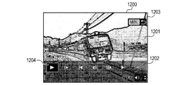
S803では、システム制御部50は、操作パネルを表示部28に表示する。例えば、図12の画面1200が表示される。画面1200は、再生対象の動画のフレーム1201、動画再生に関する各種ユーザー操作のための操作パネル1202、及び、動画表示処理を終了して再生モード処理に戻るためのユーザー操作を表すアイコン1203を含む。動画の再生を開始していない場合には動画の先頭フレームがフレーム1201として表示され、動画の再生中にはフレーム1201として表示されるフレームが時間経過によって順次変化する。操作パネル1202は、動画の再生開始を指示するための再生ボタン11204を含む。操作パネル1202は、コマ送りを指示するためのボタン、コマ戻しを指示するためのボタン、スロー再生を指示するためのボタン、等も含む。操作パネル1202は、編集モードへの遷移を指示するためのボタン、表示しているフレームの時間位置を表すインジケータバー、音量調整を指示するためのボタン、等も含む。アイコン1203は、動画表示処理を終了して再生モード処理に戻るためのユーザー操作がメニューボタン70eの押下であることを表している。 In S803, the system control unit 50 displays the operation panel on the display unit 28. For example, the screen 1200 of FIG. 12 is displayed. The screen 1200 includes a frame 1201 of a moving image to be played back, an operation panel 1202 for various user operations related to moving image playback, and an icon 1203 representing a user operation for ending the moving image display processing and returning to the playback mode processing. When the reproduction of the moving image is not started, the first frame of the moving image is displayed as the frame 1201, and the frame displayed as the frame 1201 changes sequentially with the passage of time during the reproduction of the moving image. The operation panel 1202 includes a playback button 11204 for instructing the start of playback of the moving image. The operation panel 1202 also includes a button for instructing frame advance, a button for instructing frame return, a button for instructing slow playback, and the like. The operation panel 1202 also includes a button for instructing the transition to the edit mode, an indicator bar indicating the time position of the displayed frame, a button for instructing the volume adjustment, and the like. Icon 1203 indicates that the user operation for ending the moving image display processing and returning to the playback mode processing is pressing the menu button 70e.

S804では、システム制御部50は、ユーザーにより動画再生指示(再生ボタン1204の選択など)がされたか否かを判定する。動画再生指示がされた場合はS807に進み、そうでない場合はS805に進む。 In S804, the system control unit 50 determines whether or not a moving image reproduction instruction (selection of the reproduction button 1204, etc.) has been given by the user. If the video playback instruction is given, the process proceeds to S807, and if not, the process proceeds to S805.

S805では、システム制御部50は、ユーザーにより動画表示処理の終了指示(メニューボタン70eの押下など)がされたか否かを判定する。動画表示処理の終了指示がされた場合は動画表示処理を終了し、そうでない場合はS806に進む。 In S805, the system control unit 50 determines whether or not the user has given an instruction to end the moving image display process (such as pressing the menu button 70e). If the instruction to end the moving image display process is given, the moving image display process is ended, and if not, the process proceeds to S806.

S806では、システム制御部50は、他のユーザ操作が行われた場合に当該ユーザ操作に応じた処理を行う。例えば、再生時における動画の音量の調整、コマ送り、コマ戻し、スロー再生、動画編集、等が行われる。 In S806, the system control unit 50 performs processing according to the user operation when another user operation is performed. For example, adjustment of the volume of the moving image at the time of reproduction, frame advance, frame return, slow playback, moving image editing, and the like are performed.

S807では、システム制御部50は、動画再生処理を行う。これにより、動画の進行映像が表示部28に表示される。 In S807, the system control unit 50 performs a moving image reproduction process. As a result, the progress image of the moving image is displayed on the display unit 28.

S808では、システム制御部50は、ユーザーにより動画再生の停止指示がされたか
否かを判定する。動画再生の停止指示がされた場合はS803に進み、そうでない場合はS807に進む。S808からS803に進む際に、システム制御部50は、動画再生の停止処理を行う。それにより、画面1200のフレーム1201が順次変化しなくなる。
In S808, the system control unit 50 determines whether or not the user has instructed to stop the video reproduction. If the instruction to stop the video reproduction is given, the process proceeds to S803, and if not, the process proceeds to S807. When proceeding from S808 to S803, the system control unit 50 performs a moving image reproduction stop process. As a result, the frame 1201 of the screen 1200 does not change sequentially.

SDR接続モードでの接続がされている場合の動画表示処理でも、図8(A)と同様の処理が行われる。但し、図8(A)の説明における「表示部28」を「外部表示部301」に読み替えた処理が行われる。 In the moving image display processing when the connection is made in the SDR connection mode, the same processing as in FIG. 8A is performed. However, the process of replacing the "display unit 28" in the description of FIG. 8A with the "external display unit 301" is performed.

図8(B)は、HDR接続モードでの接続がされている場合の動画表示処理(図6のS620)の詳細を示すフローチャートである。この処理は、不揮発性メモリ56に記録されたプログラムをシステムメモリ52に展開してシステム制御部50が実行することで実現する。この処理の開始前には、図18(B)の動画再生準備画面1850と同様の動画再生準備画面が外部表示部301に表示されている(図6のS618)。 FIG. 8B is a flowchart showing the details of the moving image display process (S620 in FIG. 6) when the connection is made in the HDR connection mode. This process is realized by expanding the program recorded in the non-volatile memory 56 to the system memory 52 and executing the program by the system control unit 50. Before the start of this process, a video playback preparation screen similar to the video playback preparation screen 1850 of FIG. 18B is displayed on the external display unit 301 (S618 of FIG. 6).

S811では、システム制御部50は、ユーザーにより動画再生の指示がされたか否かを判定する。動画再生の指示がされた場合はS821に進み、そうでない場合はS812に進む。 In S811, the system control unit 50 determines whether or not the user has instructed to play the moving image. If the video playback instruction is instructed, the process proceeds to S821, and if not, the process proceeds to S812.

S821では、システム制御部50は、設定されている接続モードをHDR接続モードからSDR接続モードに切り替え、SDR接続モードでの接続のための外部接続処理(図5(D)で前述したSDR接続処理;再接続処理)を行う。続いて、S817に進み、動画再生処理を行う。これにより、動画の進行映像が外部機器300に出力され、外部表示部301に表示される。 In S821, the system control unit 50 switches the set connection mode from the HDR connection mode to the SDR connection mode, and the external connection process for connection in the SDR connection mode (SDR connection process described above in FIG. 5D). ; Reconnect processing) is performed. Subsequently, the process proceeds to S817, and the moving image reproduction process is performed. As a result, the progress video of the moving image is output to the external device 300 and displayed on the external display unit 301.

S812では、システム制御部50は、動画再生の操作パネルの表示指示がユーザーによってされたか否かを判定する。操作パネルの表示指示がされた場合はS822に進み、そうでない場合は動画表示処理を終了する。 In S812, the system control unit 50 determines whether or not the display instruction on the operation panel for video reproduction has been given by the user. If the display instruction on the operation panel is given, the process proceeds to S822, and if not, the moving image display process is terminated.

S822では、システム制御部50は、設定されている接続モードをHDR接続モードからSDR接続モードに切り替える、SDR接続モードでの接続のための外部接続処理(図5(D)で前述したSDR接続処理;再接続処理)を行う。続いて、S813に進み、操作パネルを外部機器300に出力し、外部表示部301に表示させる。 In S822, the system control unit 50 switches the set connection mode from the HDR connection mode to the SDR connection mode, and the external connection process for connection in the SDR connection mode (SDR connection process described above in FIG. 5D). ; Reconnect processing) is performed. Subsequently, the process proceeds to S813, the operation panel is output to the external device 300, and the operation panel is displayed on the external display unit 301.

S814~S818の処理は、前述のS804~S808と同様であるので説明を省略する。ただし、映像の出力先は表示部28ではなく外部機器300である。 Since the processing of S814 to S818 is the same as that of S804 to S808 described above, the description thereof will be omitted. However, the output destination of the video is not the display unit 28 but the external device 300.

動画再生の操作パネルが出力されている状態で、S815で動画表示処理の終了指示が行われたと判定すると、S823に進む。 If it is determined in S815 that the instruction to end the video display process has been given while the operation panel for video playback is being output, the process proceeds to S823.

S823では、システム制御部50は、設定されている接続モードをSDR接続モードからHDR接続モードに切り替える、HDR接続モードでの接続のための外部接続処理(図5(C)で前述したHDR接続処理;再接続処理)を行う。 In S823, the system control unit 50 switches the set connection mode from the SDR connection mode to the HDR connection mode, and the external connection process for connection in the HDR connection mode (HDR connection process described above in FIG. 5C). ; Reconnect processing).

このように、HDR接続モードで映像を出力している場合は、画像切替操作をして動画が選択されると、画像切替操作後に最初に表示される動画の代表画像として、S618で疑似HDR変換されたものがHDR接続モードのまま出力される。そして、動画を再生することなく次の画像へ切り替えた場合、接続モードの切り替え処理を発生させずに次の画像を表示できる。したがって、ユーザーが画像切替操作を連続して行っている画像送り(または画像戻し)の状態では接続モードの切り替えは発生しないので、ユーザーは快適な速度で画像切替を連続して行うことができる。一方、疑似HDR変換した動画の代表画像
が表示されている状態で、動画の再生指示や、操作パネルの表示指示が行われた場合は、ユーザーは表示されている動画に興味を持って視聴しようとした場合であると想定される。この場合は、接続モードをHDR接続モードからSDR接続モードに切り替えて(再接続して)動画を表示する。このようにすることで、再接続の処理時間はかかるものの、SDR画質で記録されている動画を変換(疑似HDR変換)することなく表示できるので、記録された通りの正確な色味で動画を視聴することができる。動画の視聴が終了すると、S823で自動的に元のHDR接続モードに戻す。
In this way, when the video is output in the HDR connection mode, when the video is selected by performing the image switching operation, pseudo HDR conversion is performed with S618 as the representative image of the video displayed first after the image switching operation. The output is output in HDR connection mode. Then, when switching to the next image without playing the moving image, the next image can be displayed without causing the connection mode switching process. Therefore, since the connection mode is not switched in the image feed (or image return) state in which the user continuously performs the image switching operation, the user can continuously perform the image switching at a comfortable speed. On the other hand, if a video playback instruction or an operation panel display instruction is given while the representative image of the pseudo-HDR converted video is displayed, the user will be interested in watching the displayed video. It is assumed that this is the case. In this case, the connection mode is switched from the HDR connection mode to the SDR connection mode (reconnected) to display the moving image. By doing so, although it takes time to reconnect, the video recorded in SDR image quality can be displayed without conversion (pseudo HDR conversion), so the video can be displayed with the exact color as recorded. You can watch it. When the video viewing is finished, S823 automatically returns to the original HDR connection mode.

<疑似HDR変換処理>
図9(A)は、疑似HDR変換処理(図6のS603、S613、S615、及び、S617)の詳細を示すフローチャートである。この処理は、不揮発性メモリ56に記録されたプログラムをシステムメモリ52に展開してシステム制御部50が実行することで実現する。疑似HDR変換処理では、画像の階調分解能が高められると共に、画像の階調特性(階調値と輝度の対応関係)が変換される。本実施形態では、疑似HDR変換処理により、YCC422(BT.601,BT.601)のSDR画像(例えばJPEG画像)をYCC422(ST.2084,BT.2020)の疑似HDR画像に変換する例を説明する。ここで、YCC(BT.601,BT.601)は、色空間(階調特性,階調分解能)=YCC422(BT.601で規定された階調特性,BT.601で規定された階調分解能)を意味する。同様に、YCC422(ST.2084,BT.2020)は、YCC422(ST.2084で規定された階調特性,BT.2020で規定された階調分解能)を意味する。以下で述べる他の記載についても、同様の解釈方法が適用される。
<Pseudo HDR conversion processing>
FIG. 9A is a flowchart showing the details of the pseudo HDR conversion process (S603, S613, S615, and S617 in FIG. 6). This process is realized by expanding the program recorded in the non-volatile memory 56 to the system memory 52 and executing the program by the system control unit 50. In the pseudo HDR conversion process, the gradation resolution of the image is enhanced, and the gradation characteristics (correspondence between the gradation value and the brightness) of the image are converted. In this embodiment, an example of converting an SDR image (for example, a JPEG image) of YCC422 (BT.601, BT.601) into a pseudo HDR image of YCC422 (ST.2084, BT.2020) by a pseudo HDR conversion process will be described. do. Here, in YCC (BT.601, BT.601), the color space (gradation characteristic, gradation resolution) = YCC422 (gradation characteristic specified by BT.601, gradation resolution specified by BT.601). ) Means. Similarly, YCC422 (ST.2084, BT.2020) means YCC422 (gradation characteristic specified by ST.2084, gradation resolution specified by BT.2020). The same interpretation applies to the other statements described below.

S901では、システム制御部50は、メモリ32に書き込まれたYCC422(BT.601,BT.601)のSDR画像の色空間を、RGBに変換する。これにより、YCC422(BT.601,BT.601)のSDR画像が、RGB(BT.601,BT.601)の画像に変換される。 In S901, the system control unit 50 converts the color space of the SDR image of the YCC 422 (BT.601, BT.601) written in the memory 32 into RGB. As a result, the SDR image of YCC422 (BT.601, BT.601) is converted into an RGB (BT.6011, BT.601) image.

S902では、システム制御部50は、S901で得られたRGB(BT.601,BT.601)の画像の階調特性を、階調値の増加に対して輝度が線形に増加する線形特性に変換する(所定のγカーブを用いたγ変換)。これにより、RGB(BT.601,BT.601)の画像が、RGB(線形特性,BT.601)の画像に変換される。 In S902, the system control unit 50 converts the gradation characteristics of the RGB (BT.6011, BT.601) image obtained in S901 into linear characteristics in which the luminance increases linearly with the increase of the gradation value. (Γ conversion using a predetermined γ curve). As a result, the RGB (BT.601, BT.601) image is converted into the RGB (linear characteristic, BT.601) image.

S903では、システム制御部50は、S902で得られたRGB(線形特性,BT.601)の画像の階調分解能を、BT.2020で規定された階調分解能に変換する(CG変換)。これにより、RGB(線形特性,BT.601)の画像が、RGB(線形特性,BT.2020)の画像に変換される。BT.601の階調分解能からBT.2020の階調分解能に画像の階調分解能が高められると、画像の色域(表現可能な色のレンジ)が広がる。 In S903, the system control unit 50 determines the gradation resolution of the RGB (linear characteristic, BT.601) image obtained in S902 by BT. It is converted to the gradation resolution specified in 2020 (CG conversion). As a result, the RGB (linear characteristic, BT.601) image is converted into the RGB (linear characteristic, BT.2020) image. BT. From the gradation resolution of 601 to BT. When the gradation resolution of the image is increased to the gradation resolution of 2020, the color gamut (the range of colors that can be expressed) of the image is widened.

S904では、システム制御部50は、S903で得られたRGB(線形特性,BT.2020)の画像の階調特性を、ST.2084で規定された階調特性に変換する(図9(B)のγカーブを用いたγ変換)。これにより、RGB(線形特性,BT.2020)の画像が、RGB(ST.2084,BT.2020)の画像に変換される。ST.2084で規定された階調特性は、PQ(Perceptual Quantization)などと呼ばれる。 In S904, the system control unit 50 determines the gradation characteristics of the RGB (linear characteristics, BT.2020) image obtained in S903 by ST. It is converted to the gradation characteristic specified by 2084 (γ conversion using the γ curve of FIG. 9B). As a result, the RGB (linear characteristic, BT.2020) image is converted into the RGB (ST.2084, BT.2020) image. ST. The gradation characteristic defined by 2084 is called PQ (Perceptual Quantization) or the like.

S905では、システム制御部50は、S904で得られたRGB(ST.2084,BT.2020)の画像の色空間を、YCC422に変換する。これにより、RGB(ST.2084,BT.2020)の画像が、YCC422(ST.2084,BT.20
20)の疑似HDR画像に変換される。
In S905, the system control unit 50 converts the color space of the RGB (ST.2084, BT.2020) image obtained in S904 into YCC422. As a result, the RGB (ST.2084, BT.2020) image becomes YCC422 (ST.2084, BT.20).
It is converted into the pseudo HDR image of 20).

<図4~9のまとめ>
本実施形態によれば、HDR接続モードでの接続がされていない場合に、表示に時間がかかる現像処理後の画像が表示されず、表示に時間がかからないJPEG画像が表示される(図4のS406、S407、及び、S408)。HDR接続モードでの接続がされている場合にも、表示に時間がかからない疑似HDR画像が表示される(図6のS604、S616、及び、S618)。そして、表示に時間がかかる現像HDR画像を表示する場合には、疑似HDR画像が表示された後に、疑似HDR画像に代えて現像HDR画像が表示される(図6のS604とS611)。また、現像処理やRAW画像の読み込みなどの処理が完了する前に、次の画像への切替指示があると、当該処理が中断されて次の画像を表示するための処理が行われる(図6のS605、S607、及び、S609のYes)。さらに、接続モードの切り替えは表示開始の遅延をまねくが、HDR接続モードでの接続を継続(維持)したまま、JPEG画像が疑似HDR画像に変換されて表示される(図6のS616とS618)。これらにより、種々の画像が好適に表示可能となる。例えば、種々の画像を、時間をかけずに表示したり、接続モードの切り替え無しで表示したりできる。そのため、ユーザーは好適(快適)な画像鑑賞を行うことができる。
<Summary of Figures 4-9>
According to the present embodiment, when the connection is not made in the HDR connection mode, the image after the development process, which takes a long time to display, is not displayed, and the JPEG image which does not take a long time to display is displayed (FIG. 4). S406, S407, and S408). Even when the connection is made in the HDR connection mode, a pseudo HDR image that does not take a long time to be displayed is displayed (S604, S616, and S618 in FIG. 6). When displaying the developed HDR image that takes a long time to display, the developed HDR image is displayed instead of the pseudo HDR image after the pseudo HDR image is displayed (S604 and S611 in FIG. 6). Further, if there is an instruction to switch to the next image before the processing such as the development process and the reading of the RAW image is completed, the process is interrupted and the process for displaying the next image is performed (FIG. 6). S605, S607, and Yes of S609). Further, switching the connection mode causes a delay in the start of display, but the JPEG image is converted into a pseudo HDR image and displayed while the connection in the HDR connection mode is continued (maintained) (S616 and S618 in FIG. 6). .. As a result, various images can be suitably displayed. For example, various images can be displayed in a short time or without switching the connection mode. Therefore, the user can enjoy a suitable (comfortable) image viewing.

さらに、図13に示すように、HDR表示の再生画面1030などから、明るい白色がよく使われるメニュー画面1100などに切り替える指示があると、SDR接続モードへの切り替えが行われる(図6のS624)。それにより、明るい白色がよく使われる画面のギラつきを抑制して、各画面を好適な接続モードで表示できる。 Further, as shown in FIG. 13, when there is an instruction to switch from the playback screen 1030 of the HDR display to the menu screen 1100 or the like where bright white is often used, the switching to the SDR connection mode is performed (S624 of FIG. 6). .. As a result, it is possible to suppress glare on the screen, which is often used in bright white, and display each screen in a suitable connection mode.

また、接続モードの切り替えは表示開始の遅延をまねく。そのため、メニュー項目の1つの画面であるプロテクト設定切替画面1120などの場合は、画面にHDR画質で表示可能な撮影画像(対応RAW画像ファイルの画像)が含まれていても、HDR接続モードへの切り替えが行われずに、当該画面が表示される。これにより、操作の流れの中で、接続モードの切り替えによる待ち時間の発生を抑制できる。 Also, switching the connection mode causes a delay in the start of display. Therefore, in the case of the protect setting switching screen 1120, which is one of the menu items, even if the screen contains a captured image (image of a compatible RAW image file) that can be displayed in HDR image quality, the HDR connection mode is entered. The screen is displayed without switching. As a result, it is possible to suppress the occurrence of waiting time due to switching of the connection mode in the operation flow.

また、撮影時にHDR表示が行われると、表示画像と撮像画像が異なる可能性がある。そのため、図13に示すように、HDR表示の再生画面1030などから撮影待機画面1300などに切り替える指示があると、SDR接続モードへの切り替えが行われる(図6のS629)。これにより、表示画像を撮像画像に一致させることができ、使い勝手が向上する。そして、撮影確認画面1310の表示もSDR表示であるため、接続モードの切り替えによる待ち時間の発生を抑制でき、ユーザーは撮影結果の確認や次の撮影などを快適に行うことができる。 Further, if HDR display is performed at the time of shooting, the displayed image and the captured image may be different. Therefore, as shown in FIG. 13, when there is an instruction to switch from the playback screen 1030 or the like of the HDR display to the shooting standby screen 1300 or the like, the switching to the SDR connection mode is performed (S629 in FIG. 6). As a result, the displayed image can be matched with the captured image, and the usability is improved. Since the display of the shooting confirmation screen 1310 is also an SDR display, it is possible to suppress the occurrence of a waiting time due to the switching of the connection mode, and the user can comfortably check the shooting result and perform the next shooting.

HDR表示の再生画面1030と、画面1100,1120,1300,1310との間の切り替えが行われる度に、接続モードの切り替えが行われる。なお、設定されている接続モードの切り替えが行われる際に、設定されている接続モードが切り替わる旨のアイテム(メッセージなど)を含む画面が表示されてもよい。 Each time the playback screen 1030 of the HDR display and the screens 1100, 1120, 1300, and 1310 are switched, the connection mode is switched. When the set connection mode is switched, a screen including an item (message or the like) indicating that the set connection mode is switched may be displayed.

なお、撮像画像を出力したり表示したりする例を説明したが、コンピューターグラフィックなどであってもよい。また、SDR接続モードおよびHDR接続モードとは異なる接続モードが設定可能であってもよい。SDR接続モードで出力される画像はJPEG画像でなくてもよいし、その階調分解能は8bitの階調分解能でなくてもよい。例えば、8bitの階調分解能以下の階調分解能を有する画像がSDR接続モードで出力されてもよい。HDR接続モードで出力される画像の階調分解能は10bitや12bitでなくてもよい。HDR生成処理は、現像処理以外の処理を含んでもいてもよいし、現像処理を含んでいなくてもよい。HDR生成処理が施される画像の種別はRAWでなくてもよい。所
望の階調分解能と所望の階調特性を有する画像が得られれば、疑似HDR変換処理は特に限定されない。例えば、疑似HDR変換処理は色空間の変換を含まなくてもよい。HLG(Hybrid Log Gamma)と呼ばれる階調特性を有する疑似HDR画像が得られてもよい。各種画面も上述したものに限られない。
Although an example of outputting and displaying a captured image has been described, computer graphics and the like may be used. Further, a connection mode different from the SDR connection mode and the HDR connection mode may be set. The image output in the SDR connection mode does not have to be a JPEG image, and its gradation resolution does not have to be an 8-bit gradation resolution. For example, an image having a gradation resolution of 8 bits or less may be output in the SDR connection mode. The gradation resolution of the image output in the HDR connection mode does not have to be 10 bits or 12 bits. The HDR generation process may include a process other than the development process, or may not include the development process. The type of image to which HDR generation processing is performed does not have to be RAW. The pseudo HDR conversion process is not particularly limited as long as an image having a desired gradation resolution and a desired gradation characteristic can be obtained. For example, the pseudo HDR conversion process may not include color space conversion. A pseudo HDR image having a gradation characteristic called HLG (Hybrid Log Gamma) may be obtained. The various screens are not limited to those described above.

<操作受付処理>
図14(A)は、デジタルカメラ100が外部機器300に接続されていない場合の操作受付処理(図4のS409)の詳細を示すフローチャートである。この処理は、不揮発性メモリ56に記録されたプログラムをシステムメモリ52に展開してシステム制御部50が実行することで実現する。
<Operation reception process>
FIG. 14A is a flowchart showing the details of the operation acceptance process (S409 in FIG. 4) when the digital camera 100 is not connected to the external device 300. This process is realized by expanding the program recorded in the non-volatile memory 56 to the system memory 52 and executing the program by the system control unit 50.

S1401では、システム制御部50は、インフォボタン70gが押下されたか否かを判定する。インフォボタン70gが押下されたと判定された場合はS1402に進み。そうでない場合は処理を終了する。S1402では、システム制御部50は、撮影情報(撮影設定情報)を表示部28に表示しているか否かを判定する。撮影情報を表示していると判定された場合はS1403に進み。そうでない場合はS1404に進む。S1403では、システム制御部50は、輝度ヒストグラム(画像の輝度分布を示すヒストグラム)を表示部28に表示しているか否かを判定する。輝度ヒストグラムを表示していると判定された場合はS1406に進み、そうでない場合はS1405に進む。S1404では、システム制御部50は、撮影情報を表示部28に表示する。S1405では、システム制御部50は、輝度ヒストグラムを表示部28に表示する。S1406では、システム制御部50は、撮影情報と輝度ヒストグラムの表示を行わないように制御する。 In S1401, the system control unit 50 determines whether or not the info button 70g is pressed. If it is determined that the info button 70g has been pressed, the process proceeds to S1402. If not, the process ends. In S1402, the system control unit 50 determines whether or not the shooting information (shooting setting information) is displayed on the display unit 28. If it is determined that the shooting information is displayed, the process proceeds to S1403. If not, the process proceeds to S1404. In S1403, the system control unit 50 determines whether or not the luminance histogram (histogram showing the luminance distribution of the image) is displayed on the display unit 28. If it is determined that the luminance histogram is displayed, the process proceeds to S1406, and if not, the process proceeds to S1405. In S1404, the system control unit 50 displays the shooting information on the display unit 28. In S1405, the system control unit 50 displays the luminance histogram on the display unit 28. In S1406, the system control unit 50 controls so as not to display the shooting information and the luminance histogram.

図15(A)は、インフォボタン70gの押下による表示部28の表示の遷移を示す。画像(対象画像)1501のみを含む画面1500が表示部28に表示されている状態でインフォボタン70gが押下されると、図14(A)のS1404の処理により、画面1500から画面1510に表示部28の表示が遷移する。画面1510では、画像1501の上部と下部に画像1501の撮影情報1511と撮影情報1512がそれぞれ重ねられている。画面1510が表示部28に表示されている状態でインフォボタン70gが押下されると、図14(A)のS1405の処理により、画面1510から画面1520に表示部28の表示が遷移する。画面1520は、画像1501を縮小した画像1521、画像1501の輝度ヒストグラム1522、及び、画像1501の撮影情報1523を含む。画面1520が表示部28に表示されている状態でインフォボタン70gが押下されると、図14(A)のS1406の処理により、画面1520から画面1500に表示部28の表示が遷移する。 FIG. 15A shows a transition of the display of the display unit 28 by pressing the info button 70g. When the info button 70g is pressed while the screen 1500 containing only the image (target image) 1501 is displayed on the display unit 28, the display unit is displayed on the screen 1500 to the screen 1510 by the processing of S1404 in FIG. 14 (A). The display of 28 changes. On the screen 1510, the shooting information 1511 and the shooting information 1512 of the image 1501 are superimposed on the upper part and the lower part of the image 1501, respectively. When the info button 70g is pressed while the screen 1510 is displayed on the display unit 28, the display of the display unit 28 shifts from the screen 1510 to the screen 1520 by the process of S1405 in FIG. 14 (A). The screen 1520 includes an image 1521 obtained by reducing the image 1501, a brightness histogram 1522 of the image 1501, and shooting information 1523 of the image 1501. When the info button 70g is pressed while the screen 1520 is displayed on the display unit 28, the display of the display unit 28 shifts from the screen 1520 to the screen 1500 by the process of S1406 in FIG. 14 (A).

なお、画面1510の撮影情報1512と画面1520の撮影情報1523とで、表示される情報表示アイテム(情報表示の項目)の種類やサイズが異なっているものとする。例えば、撮影情報1523は、露出補正の情報1524、ホワイトバランス設定の情報1525、ホワイトバランス設定を補正する設定情報1526、及び、画像のシャープネスやコントラストを設定するピクチャースタイル設定の情報1527を含んでいる。これらの情報は、撮影情報1512には含まれていない。他の設定項目の設定内容、画像のRGB値の分布を示すヒストグラム、画像の色空間の設定情報、等が画面に含まれていてもよい。 It is assumed that the type and size of the displayed information display item (information display item) are different between the shooting information 1512 on the screen 1510 and the shooting information 1523 on the screen 1520. For example, the shooting information 1523 includes exposure compensation information 1524, white balance setting information 1525, white balance setting correction setting information 1526, and picture style setting information 1527 for setting image sharpness and contrast. .. This information is not included in the shooting information 1512. The screen may include setting contents of other setting items, a histogram showing the distribution of RGB values of the image, setting information of the color space of the image, and the like.

SDR接続モードでの接続がされている場合の操作受付処理でも、図14(A)と同様の処理が行われる。但し、図14(A)の説明における「表示部28」を「外部表示部301」に読み替えた処理が行われる。 In the operation acceptance process when the connection is made in the SDR connection mode, the same process as in FIG. 14A is performed. However, the process of replacing the "display unit 28" in the description of FIG. 14A with the "external display unit 301" is performed.

図14(B)は、HDR接続モードでの接続がされている場合の操作受付処理(図6の
S619)の詳細を示すフローチャートである。この処理は、不揮発性メモリ56に記録されたプログラムをシステムメモリ52に展開してシステム制御部50が実行することで実現する。
FIG. 14B is a flowchart showing the details of the operation acceptance process (S619 in FIG. 6) when the connection is made in the HDR connection mode. This process is realized by expanding the program recorded in the non-volatile memory 56 to the system memory 52 and executing the program by the system control unit 50.

S1411では、システム制御部50は、インフォボタン70gが押下されたか否かを判定する。インフォボタン70gが押下されたと判定された場合はS1412に進み。そうでない場合は処理を終了する。S1412では、システム制御部50は、撮影情報を外部機器300に出力しているか否かを判定する。撮影情報を出力していると判定された場合はS1414に進み。そうでない場合はS1413に進む。S1413では、システム制御部50は、撮影情報を外部機器300に出力して表示する。S1414では、システム制御部50は、撮影情報の出力を行わないように制御する。 In S1411, the system control unit 50 determines whether or not the info button 70g is pressed. If it is determined that the info button 70g has been pressed, the process proceeds to S1412. If not, the process ends. In S1412, the system control unit 50 determines whether or not the shooting information is output to the external device 300. If it is determined that the shooting information is being output, the process proceeds to S1414. If not, the process proceeds to S1413. In S1413, the system control unit 50 outputs and displays the shooting information to the external device 300. In S1414, the system control unit 50 controls so as not to output shooting information.

図15(B)は、インフォボタン70gの押下による外部表示部301の表示の遷移を示す。画像1531のみを含む画面1530が外部表示部301に表示されている状態でインフォボタン70gが押下されると、図14(B)のS1413の処理により、画面1530から画面1540に外部表示部301の表示が遷移する。画面1540では、画像1531の上部と下部に画像1531の撮影情報1541と撮影情報1542がそれぞれ重ねられている。また、HDR表示(HDR接続モードでの接続)が行われていることを表すアイコン1543が表示されている。画面1540が外部表示部301に表示されている状態でインフォボタン70gが押下されると、図14(B)のS1414の処理により、画面1540から画面1530に外部表示部301の表示が遷移する。 FIG. 15B shows a transition of the display of the external display unit 301 by pressing the info button 70g. When the info button 70g is pressed while the screen 1530 containing only the image 1531 is displayed on the external display unit 301, the external display unit 301 is displayed from the screen 1530 to the screen 1540 by the process of S1413 in FIG. 14 (B). The display changes. On the screen 1540, the shooting information 1541 and the shooting information 1542 of the image 1531 are superimposed on the upper part and the lower part of the image 1531, respectively. In addition, an icon 1543 indicating that HDR display (connection in HDR connection mode) is being performed is displayed. When the info button 70g is pressed while the screen 1540 is displayed on the external display unit 301, the display of the external display unit 301 shifts from the screen 1540 to the screen 1530 by the process of S1414 in FIG. 14 (B).

このように、HDR接続モードでの接続が行われている場合には、システム制御部50は、画面1520のような輝度ヒストグラムを表示し、画像を縮小して画像以外が占める面積の大きい画面である所定の画面に遷移しないように画面遷移の制御を行う。これによって、HDR接続モードでの接続がされている場合に、輝度ヒストグラムは表示されない。前述したとおり、デジタルカメラ100の本体モニタである表示部28では、対応RAW画像であってもRAW画像ファイルに含まれる表示用JPEGがSDR画質で表示される。この時表示されるヒストグラムは、表示部28に表示されたSDR画質の画像に基づいて算出される。一方、同じ対応RAW画像をHDR現像処理してHDR画質で表示している際に、本体モニタの場合と同じヒストグラムを表示してしまうと、ユーザーが外部表示部301で見ている映像とヒストグラムは正確には一致しなくなる。これは、本体モニタの場合のヒストグラムは、表示されているHDR画質の映像に基づいて算出されたヒストグラムではないからである。一例として、本体モニタでは空の白い部分が飽和しており、ヒストグラムでは輝度の最大値が多いヒストグラムとなっている場合を考える。この場合でも、外部表示部301でHDR表示した場合には、空の白い部分について飽和する部分が少なく、本体モニタよりも階調豊かに表示される場合がある。この場合、輝度の最大値が多いヒストグラムは外部表示部301での画像の見た目と正確に一致しなくなるため、ユーザーに違和感を与える。逆に、同じ対応RAW画像をHDR現像処理したHDR画質の画像に基づいてヒストグラムを算出して表示すると、同じ画像についてのヒストグラムであるのに、本体モニタで見た場合と外部表示部301で見た場合とでヒストグラムが違うものになってしまう。そのため、やはり、ユーザーに違和感を与える。そこで、本実施形態のように、HDR接続モードで出力している際にヒストグラムを表示しないようにすれば、ユーザーがHDR画質での映像を見ながらヒストグラム情報を参照することはない。従って、ユーザーの違和感、露出などに対するユーザの誤判断、ユーザによる誤った撮影設定、等を抑制でき、ユーザーの認識とは異なる画像の撮影などを抑制できる。 In this way, when the connection is made in the HDR connection mode, the system control unit 50 displays a luminance histogram like the screen 1520, reduces the image, and displays a screen with a large area other than the image. The screen transition is controlled so as not to transition to a predetermined screen. As a result, the luminance histogram is not displayed when the connection is made in the HDR connection mode. As described above, the display unit 28, which is the main body monitor of the digital camera 100, displays the display JPEG included in the RAW image file in SDR image quality even if it is a corresponding RAW image. The histogram displayed at this time is calculated based on the image of SDR image quality displayed on the display unit 28. On the other hand, if the same compatible RAW image is HDR-developed and displayed in HDR image quality and the same histogram as in the case of the main unit monitor is displayed, the image and histogram that the user is viewing on the external display unit 301 will be displayed. It will not match exactly. This is because the histogram in the case of the main body monitor is not a histogram calculated based on the displayed HDR image quality image. As an example, consider the case where the white part of the sky is saturated on the main body monitor and the histogram has a large maximum luminance value. Even in this case, when HDR is displayed on the external display unit 301, there are few saturated parts in the white part of the sky, and the display may be richer in gradation than the main body monitor. In this case, the histogram having a large maximum luminance value does not exactly match the appearance of the image on the external display unit 301, which gives the user a sense of discomfort. Conversely, when a histogram is calculated and displayed based on an HDR-developed HDR image of the same corresponding RAW image, the histogram is for the same image, but it is viewed on the main unit monitor and on the external display unit 301. The histogram will be different depending on the case. Therefore, it still gives the user a sense of discomfort. Therefore, if the histogram is not displayed when the output is performed in the HDR connection mode as in the present embodiment, the user does not refer to the histogram information while viewing the image in HDR image quality. Therefore, it is possible to suppress the user's discomfort, misjudgment of the user regarding exposure, erroneous shooting setting by the user, and the like, and it is possible to suppress shooting of an image different from the user's recognition.

また、画像を縮小して画像以外が占める面積(例えば単色の白色などで表示される可能性のある面積)の大きい画面への遷移も抑制されているため、単色の白色表示などによる画面のギラつきを抑制できる。 In addition, since the transition to a screen in which the image is reduced and the area occupied by other than the image (for example, the area that may be displayed in a single color white) is large is suppressed, the screen glare due to the single color white display or the like is suppressed. It can suppress sticking.

なお、HDR接続モードでの接続が行われている場合には、画面1520のような詳細な撮影情報を表示する画面に遷移してもよい。しかし、SDR表示とHDR表示とでの画像の見えの差に関係のある情報(輝度、階調、色味の少なくとも1つに関する情報表示アイテム)は表示されないことが好ましい。例えば、露出補正の情報、ホワイトバランス設定の情報、ホワイトバランス設定を補正する設定情報、画像のシャープネスやコントラストを設定するピクチャースタイル設定の情報は表示されないことが好ましい。また、画像のRGB値の分布を示すヒストグラム、画像の色空間の設定情報、等も表示されないことが好ましい。 When the connection is made in the HDR connection mode, the screen may transition to a screen displaying detailed shooting information such as the screen 1520. However, it is preferable that the information related to the difference in the appearance of the image between the SDR display and the HDR display (information display item relating to at least one of luminance, gradation, and color) is not displayed. For example, it is preferable that the exposure compensation information, the white balance setting information, the white balance setting correction setting information, and the picture style setting information for setting the sharpness and contrast of the image are not displayed. Further, it is preferable that the histogram showing the distribution of RGB values of the image, the setting information of the color space of the image, and the like are not displayed.

また、画面1540から画面1530への遷移の際に、システム制御部50は、輝度ヒストグラムを表示する画面に遷移できないことを示すガイダンス1551を含む画面1550を外部機器300に一時的に出力して表示してもよい(図15(C))。さらに、システム制御部50は、ガイダンス1551の画面1550を出力した後に、HDR接続モードを解除してSDR接続モードを設定するか否かのガイダンスを含む画面を外部機器300に出力して表示してもよい。HDR接続モードを解除する指示があった場合は、システム制御部50は、設定されている接続モードをHDR接続モードからSDR接続モードに切り替え、SDR接続処理を行う。SDR接続モードが設定されることで、画面1520のような画面に遷移できるようになる。また、所定の閾値以上の輝度情報を持つ画像領域を点滅表示などで強調する処理(ハイライト警告表示)を行える場合は、画像1531を表示している状態において、当該処理を行わないようにしてもよい。 Further, at the time of transition from screen 1540 to screen 1530, the system control unit 50 temporarily outputs and displays the screen 1550 including the guidance 1551 indicating that the transition to the screen displaying the luminance histogram cannot be performed to the external device 300. It may be (FIG. 15 (C)). Further, after outputting the screen 1550 of the guidance 1551, the system control unit 50 outputs and displays a screen including guidance on whether to cancel the HDR connection mode and set the SDR connection mode to the external device 300. May be good. When instructed to cancel the HDR connection mode, the system control unit 50 switches the set connection mode from the HDR connection mode to the SDR connection mode, and performs the SDR connection process. By setting the SDR connection mode, it becomes possible to transition to a screen such as the screen 1520. If a process (highlight warning display) that emphasizes an image area having luminance information equal to or higher than a predetermined threshold value by blinking display or the like can be performed, the process should not be performed while the image 1531 is displayed. May be good.

<スライドショー処理>
図16(A)は、スライドショー処理(図7のS714)の詳細を示すフローチャートである。この処理は、不揮発性メモリ56に記録されたプログラムをシステムメモリ52に展開してシステム制御部50が実行することで実現する。
<Slide show processing>
FIG. 16A is a flowchart showing the details of the slide show process (S714 of FIG. 7). This process is realized by expanding the program recorded in the non-volatile memory 56 to the system memory 52 and executing the program by the system control unit 50.

S1601では、システム制御部50は、HDR接続モードフラグが1に設定されているか否かを判定する。設定されている場合はS1602に進み、そうでない場合はS1603に進む。S1602では、システム制御部50は、S501と同様に、外部機器300がHDRに対応しているか否かを判定する。対応していると判定された場合はS1604に進み、そうでない場合はS1603に進む。S1603では、システム制御部50は、図16(B)のスライドショー処理を実行する。S1604では、システム制御部50は、図17のスライドショー処理を実行する。 In S1601, the system control unit 50 determines whether or not the HDR connection mode flag is set to 1. If it is set, the process proceeds to S1602, and if not, the process proceeds to S1603. In S1602, the system control unit 50 determines whether or not the external device 300 supports HDR, as in S501. If it is determined that they correspond, the process proceeds to S1604, and if not, the process proceeds to S1603. In S1603, the system control unit 50 executes the slide show process of FIG. 16B. In S1604, the system control unit 50 executes the slide show process of FIG.

図16(B)は、図16(A)のS1603で行われるスライドショー処理の詳細を示すフローチャートである。この処理は、不揮発性メモリ56に記録されたプログラムをシステムメモリ52に展開してシステム制御部50が実行することで実現する。なお、図16(B)のスライドショー処理における各種画面は、デジタルカメラ100が外部機器300に接続されていない場合には表示部28に、SDR接続モードでの接続がされている場合には外部表示部301に表示される。 16 (B) is a flowchart showing the details of the slide show processing performed in S1603 of FIG. 16 (A). This process is realized by expanding the program recorded in the non-volatile memory 56 to the system memory 52 and executing the program by the system control unit 50. The various screens in the slide show processing of FIG. 16B are displayed on the display unit 28 when the digital camera 100 is not connected to the external device 300, and externally displayed when the digital camera 100 is connected in the SDR connection mode. It is displayed in the unit 301.

S1611では、システム制御部50は、図18(A)に示すスライドショー開始準備画面1800を表示する。 In S1611, the system control unit 50 displays the slide show start preparation screen 1800 shown in FIG. 18A.

S1612では、システム制御部50は、スライドショー処理で最初に表示する画像のファイルから、当該画像の情報(メタデータ、ファイル名、等)を取得する。 In S1612, the system control unit 50 acquires information (metadata, file name, etc.) of the image from the file of the image to be displayed first in the slide show processing.

S1613では、システム制御部50は、スライドショー開始準備画面を非表示にする。 In S1613, the system control unit 50 hides the slide show start preparation screen.

S1614では、システム制御部50は、表示対象の画像を表示する。S1614の処理は、表示対象が静止画ファイルの画像である場合は、図4のS404~S407の処理と同様である。表示対象が動画である場合は図8のS807と同様の処理である。なお、図4などの説明では省略したが、画像を表示する際に、システム制御部50は、表示する画像(画像データ)を記録媒体200から読み込みんでメモリ32へ展開する。そして、システム制御部50は、展開した画像のフォーマット・サイズを表示部28や外部表示部301で表示できるフォーマット・サイズに画像処理部24でデコード・リサイズする。処理された画像はメモリ32に格納される。 In S1614, the system control unit 50 displays an image to be displayed. The processing of S1614 is the same as the processing of S404 to S407 of FIG. 4 when the display target is an image of a still image file. When the display target is a moving image, the process is the same as that of S807 in FIG. Although omitted in the description of FIG. 4, when displaying an image, the system control unit 50 reads the image (image data) to be displayed from the recording medium 200 and expands it into the memory 32. Then, the system control unit 50 decodes and resizes the format size of the expanded image to a format size that can be displayed by the display unit 28 and the external display unit 301 by the image processing unit 24. The processed image is stored in the memory 32.

S1615では、システム制御部50は、S1614の画像表示からスライドショーの1枚当たりの表示時間として予め設定された所定時間(切替間隔)が経過したか否かを判定する。所定時間が経過したと判定された場合はS1616に進み、そうでない場合はS1617に進む。なお、表示対象が動画である場合には、S1615の処理は所定時間が経過したか否かではなく、動画を終端まで再生したか、または画像の切り替え操作が行われたかの判定となる。何れかが真となるとS1616に進み、そうでない場合にはS1617に進む。 In S1615, the system control unit 50 determines whether or not a predetermined time (switching interval) preset as a display time per slide show has elapsed from the image display of S1614. If it is determined that the predetermined time has elapsed, the process proceeds to S1616, and if not, the process proceeds to S1617. When the display target is a moving image, the process of S1615 is not whether or not a predetermined time has elapsed, but whether or not the moving image has been reproduced to the end or whether or not the image switching operation has been performed. If any of them is true, the process proceeds to S1616, and if not, the process proceeds to S1617.

S1616では、システム制御部50は、次に表示する画像のファイルから、当該画像の情報(メタデータ、ファイル名、等)を取得する。 In S1616, the system control unit 50 acquires information (metadata, file name, etc.) of the image from the file of the image to be displayed next.

S1617では、システム制御部50は、スライドショー処理を終了するか否かを判定する。システム制御部50は、ユーザーによりスライドショー終了の指示がされた場合、スライドショー処理で再生対象とされる全ての画像の表示が完了した場合、等において、スライドショー処理を終了すると判定し、それらでない場合に終了しないと判定する。スライドショー処理を終了すると判定された場合はスライドショー処理を終了し、そうでない場合はS1615に進む。 In S1617, the system control unit 50 determines whether or not to end the slide show processing. The system control unit 50 determines that the slide show processing is terminated when the user instructs the end of the slide show, the display of all the images to be reproduced in the slide show processing is completed, and the like, and when they are not. Judge that it does not end. If it is determined that the slide show processing is finished, the slide show processing is finished, and if not, the process proceeds to S1615.

図17は、図16(A)のS1604で行われるスライドショー処理の詳細を示すフローチャートである。この処理は、不揮発性メモリ56に記録されたプログラムをシステムメモリ52に展開してシステム制御部50が実行することで実現する。 FIG. 17 is a flowchart showing details of the slide show processing performed in S1604 of FIG. 16A. This process is realized by expanding the program recorded in the non-volatile memory 56 to the system memory 52 and executing the program by the system control unit 50.

S1701では、システム制御部50は、SDR接続モードフラグを1に設定する。SDR接続モードフラグは、SDR接続モードの設定が一時的なものであるか否かを示す。 In S1701, the system control unit 50 sets the SDR connection mode flag to 1. The SDR connection mode flag indicates whether or not the SDR connection mode setting is temporary.

S1702では、システム制御部50は、スライドショー開始準備画面を、出力I/F91を介して外部機器300に出力する。これにより、図18(A)に示すように、スライドショー開始準備画面1800が外部表示部301に表示される。 In S1702, the system control unit 50 outputs the slide show start preparation screen to the external device 300 via the output I / F 91. As a result, as shown in FIG. 18A, the slide show start preparation screen 1800 is displayed on the external display unit 301.

S1704では、システム制御部50は、スライドショー処理で最初に出力する画像のファイルから、当該画像の情報(メタデータ、ファイル名、等)を取得する。 In S1704, the system control unit 50 acquires information (metadata, file name, etc.) of the image from the image file that is first output in the slide show processing.

S1705では、システム制御部50は、S1704や後述のS1728で取得した情報(出力する画像のメタデータ、ファイル名、等)から、出力する画像が動画であるか否かを判定する。動画である場合はS1706に進み、そうでない場合はS1715に進む。 In S1705, the system control unit 50 determines whether or not the output image is a moving image from the information (metadata of the output image, file name, etc.) acquired in S1704 and S1728 described later. If it is a moving image, proceed to S1706, and if not, proceed to S1715.

S1706では、システム制御部50は、SDR接続モードフラグが0に設定されているか否かを判定する。0に設定されている場合はS1707に進み、そうでない場合はS1711に進む。 In S1706, the system control unit 50 determines whether or not the SDR connection mode flag is set to 0. If it is set to 0, the process proceeds to S1707, and if not, the process proceeds to S1711.

S1707では、システム制御部50は、設定されている接続モードをHDR接続モードからSDR接続モードに切り替える、図5(D)で前述したSDR接続処理を行う。S1708では、システム制御部50は、SDR接続モードフラグを1に設定する。 In S1707, the system control unit 50 performs the SDR connection process described above in FIG. 5D, in which the set connection mode is switched from the HDR connection mode to the SDR connection mode. In S1708, the system control unit 50 sets the SDR connection mode flag to 1.

S1709では、システム制御部50は、出力する動画を記録媒体200から読み出し、当該動画の先頭フレーム(停止映像)を外部機器300に出力して表示する。 In S1709, the system control unit 50 reads the moving image to be output from the recording medium 200, outputs the first frame (stopped image) of the moving image to the external device 300, and displays the moving image.

S1710では、システム制御部50は、先頭フレームを出力してから所定時間(SDR接続処理に要すると想定される時間よりも長い時間であり、5秒程度以上)が経過したか否かを判定する。ここでの所定時間は、前述の切替間隔(スライドショーの1枚当たりの表示時間として予め設定された時間)とは無関係の時間であり、前述の切り替え時間とは別に独立して設定された時間である。また、ここでの所定時間は、少なくとも動画の進行映像を出力する場合のフレームレートの1フレーム分の時間(30fpsであれば1/30秒)よりも長い。また、少なくとも、0.3秒以上である。所定時間が経過したと判定された場合はS1711に進み、そうでない場合はS1710に進む。なお、複数の動画の出力が連続する場合には、2つ目以降の動画についてはS1706でNoと判定されるため、S1709の処理(停止映像の出力)とS1710の処理(所定時間の待機)とは省略される。 In S1710, the system control unit 50 determines whether or not a predetermined time (a time longer than the time expected to be required for the SDR connection process, about 5 seconds or more) has elapsed since the first frame was output. .. The predetermined time here is a time irrelevant to the above-mentioned switching interval (time preset as the display time per slide show), and is a time set independently of the above-mentioned switching time. be. Further, the predetermined time here is longer than at least one frame's time (1/30 second at 30 fps) when outputting a moving image of a moving image. Moreover, it is at least 0.3 seconds or more. If it is determined that the predetermined time has elapsed, the process proceeds to S1711, and if not, the process proceeds to S1710. When the output of a plurality of moving images is continuous, the second and subsequent moving images are determined to be No in S1706, so that the processing of S1709 (output of stopped video) and the processing of S1710 (waiting for a predetermined time). Is abbreviated.

S1711では、システム制御部50は、先頭フレームからの動画再生処理を行う。これにより、動画の進行映像が外部機器300に出力されて表示される。 In S1711, the system control unit 50 performs a moving image reproduction process from the first frame. As a result, the progress video of the moving image is output to the external device 300 and displayed.

S1712では、システム制御部50は、ユーザーにより画像切替操作が行われたか否かを判定する。画像切替操作が行われたと判定された場合はS1713に進み、そうでない場合はS1714に進む。 In S1712, the system control unit 50 determines whether or not the image switching operation has been performed by the user. If it is determined that the image switching operation has been performed, the process proceeds to S1713, and if not, the process proceeds to S1714.

S1713では、システム制御部50は、動画再生の停止処理を行う。 In S1713, the system control unit 50 performs a moving image reproduction stop process.

S1714では、システム制御部50は、動画が最後まで(終端まで)再生されたか否かを判定する。最後まで再生されたと判定された場合はS1728に進み、そうでない場合はS1712に進む。 In S1714, the system control unit 50 determines whether or not the moving image has been played to the end (until the end). If it is determined that the reproduction has been completed to the end, the process proceeds to S1728, and if not, the process proceeds to S1712.

一方、出力する画像が静止画である場合には、S1715で、システム制御部50は、SDR接続モードフラグが1に設定されているか否かを判定する。設定されている場合はS1716に進み、そうでない場合はS1718に進む。 On the other hand, when the image to be output is a still image, in S1715, the system control unit 50 determines whether or not the SDR connection mode flag is set to 1. If it is set, the process proceeds to S1716, and if not, the process proceeds to S1718.

S1716では、システム制御部50は、設定されている接続モードをSDR接続モードからHDR接続モードに切り替える、図5(C)で前述したHDR接続処理を行う。S1717では、システム制御部50は、SDR接続モードフラグを0に設定する。 In S1716, the system control unit 50 performs the HDR connection process described above in FIG. 5C, which switches the set connection mode from the SDR connection mode to the HDR connection mode. In S1717, the system control unit 50 sets the SDR connection mode flag to 0.

S1718では、システム制御部50は、S1704や後述のS1728で取得した情報(出力する画像のメタデータ、ファイル名、等)から、出力する画像が対応RAW画像か否かを判定する。対応RAW画像と判定された場合はS1719に進み、そうでない場合はS1722に進む。 In S1718, the system control unit 50 determines whether or not the output image is a corresponding RAW image from the information (metadata of the output image, file name, etc.) acquired in S1704 and S1728 described later. If it is determined to be a corresponding RAW image, the process proceeds to S1719, and if not, the process proceeds to S1722.

S1719では、システム制御部50は、出力する対応RAW画像を、記録媒体200から読み込み、メモリ32に展開する。S1720では、システム制御部50は、S1719でメモリ32に展開された対応RAW画像から現像HDR画像を生成するHDR現像処理を行う。S1721では、システム制御部50は、S1720で生成された現像HD
R画像を外部機器300に出力して表示する。
In S1719, the system control unit 50 reads the corresponding RAW image to be output from the recording medium 200 and expands it into the memory 32. In S1720, the system control unit 50 performs HDR development processing for generating a developed HDR image from the corresponding RAW image expanded in the memory 32 in S1719. In S1721, the system control unit 50 uses the developed HD generated in S1720.
The R image is output to the external device 300 and displayed.

S1722では、システム制御部50は、S1704や後述のS1728で取得した情報(出力する画像のメタデータ、ファイル名、等)から、出力する画像が非対応RAW画像か否かを判定する。非対応RAW画像と判定された場合はS1723に進み、そうでない場合はS1724に進む。 In S1722, the system control unit 50 determines whether or not the output image is a non-compliant RAW image from the information (metadata of the output image, file name, etc.) acquired in S1704 and S1728 described later. If it is determined that the image is not compatible with RAW, the process proceeds to S1723, and if not, the process proceeds to S1724.

S1723では、システム制御部50は、出力する非対応RAW画像に関連付けられて記録された表示用JPEG画像を疑似HDR画像に変換する。S1724では、システム制御部50は、出力するJPEG画像を疑似HDR画像に変換する(図9(A)で前述した処理)。S1724のJPEG画像は、RAWファイルに含まれた表示用JPEG画像ではなく、独立したJPEGファイルの画像である。S1725では、システム制御部50は、S1723またはS1724で生成された疑似HDR画像を外部機器300に出力して表示する。 In S1723, the system control unit 50 converts the display JPEG image associated with the output non-corresponding RAW image and recorded into a pseudo HDR image. In S1724, the system control unit 50 converts the output JPEG image into a pseudo HDR image (the process described above in FIG. 9A). The JPEG image of S1724 is not a display JPEG image included in the RAW file, but an image of an independent JPEG file. In S1725, the system control unit 50 outputs the pseudo HDR image generated in S1723 or S1724 to the external device 300 and displays it.

S1726では、システム制御部50は、S1721またはS1725で画像を出力してから所定時間(スライドショー1枚当たりの表示時間として予め設定された切替間隔)が経過したか否かを判定する。所定時間が経過したと判定された場合はS1728に進み、そうでない場合はS1727に進む。S1726の所定時間は、S1710の所定時間と異なっていてもよいし、同じであってもよい。 In S1726, the system control unit 50 determines whether or not a predetermined time (a switching interval preset as a display time per slide show) has elapsed since the image was output in S1721 or S1725. If it is determined that the predetermined time has elapsed, the process proceeds to S1728, and if not, the process proceeds to S1727. The predetermined time of S1726 may be different from or the same as the predetermined time of S1710.

S1727では、システム制御部50は、ユーザーにより画像切替操作が行われたか否かを判定する。画像切替操作が行われたと判定された場合はS1728に進み、そうでない場合はS1729に進む。 In S1727, the system control unit 50 determines whether or not the image switching operation has been performed by the user. If it is determined that the image switching operation has been performed, the process proceeds to S1728, and if not, the process proceeds to S1729.

S1728では、システム制御部50は、次に出力する画像のファイルから、当該画像の情報(メタデータ、ファイル名、等)を取得する。 In S1728, the system control unit 50 acquires information (metadata, file name, etc.) of the image from the image file to be output next.

S1729では、システム制御部50は、スライドショー処理を終了するか否かを判定する。スライドショー処理を終了すると判定された場合はスライドショー処理を終了し、そうでない場合はS1726に進む。 In S1729, the system control unit 50 determines whether or not to end the slide show processing. If it is determined that the slide show processing is finished, the slide show processing is finished, and if not, the process proceeds to S1726.

図18(A)は、図17のスライドショー処理における画面の遷移例を示す。 FIG. 18A shows an example of screen transition in the slide show processing of FIG.

まず、図17のS1702の処理により、スライドショー開始準備画面1800が外部表示部301に表示される。スライドショー開始準備画面1800が表示されている間に、S1704の情報取得が行われる。 First, by the process of S1702 in FIG. 17, the slide show start preparation screen 1800 is displayed on the external display unit 301. While the slide show start preparation screen 1800 is displayed, the information of S1704 is acquired.

最初の出力画像が、対応RAW画像、非対応RAW画像、及び、JPEG画像のいずれかである場合には、HDR接続モードでの接続に切り替えられる。そして、S1721またはS1725の処理により、それら画像のいずれかの画面1810がHDR接続モードで外部表示部301に表示される(HDR表示)。このとき、SDR接続モードフラグは0である。この状態で、画像切替操作または所定時間の経過により次の画像に切り替わり、次の画像が動画であった場合は、S1707でSDR接続処理が行われることになる。 If the first output image is any of a corresponding RAW image, a non-corresponding RAW image, and a JPEG image, the connection is switched to HDR connection mode. Then, by the processing of S1721 or S1725, the screen 1810 of any of those images is displayed on the external display unit 301 in the HDR connection mode (HDR display). At this time, the SDR connection mode flag is 0. In this state, the image is switched to the next image by the image switching operation or the lapse of a predetermined time, and if the next image is a moving image, the SDR connection process is performed in S1707.

S1707のSDR接続処理中には、接続モードの切り替え途中の表示が見えないように、画像の出力が停止され、外部表示部301の表示画面が画面1810から画面1820に遷移する。 During the SDR connection process of S1707, the output of the image is stopped so that the display during the switching of the connection mode cannot be seen, and the display screen of the external display unit 301 transitions from the screen 1810 to the screen 1820.

ここで、S1711の動画再生処理(進行映像の出力)が直ちに行われる場合を考える
。この場合には、外部表示部301が表示を行うための準備が完了する前に、進行映像がデジタルカメラ100から出力されることがある。準備が完了する前に進行映像が出力されると、動画の冒頭部分が外部表示部301に表示されず、画面1830に示すように動画の途中から外部表示部301に表示されるため、ユーザーが冒頭部分を見ることができない。
Here, consider a case where the moving image reproduction process (output of the progress image) of S1711 is immediately performed. In this case, the progress image may be output from the digital camera 100 before the preparation for displaying is completed by the external display unit 301. If the progress video is output before the preparation is completed, the beginning part of the video is not displayed on the external display unit 301, but is displayed on the external display unit 301 from the middle of the video as shown on the screen 1830. I can't see the beginning.

そこで、本実施形態では、デジタルカメラ100は、SDR接続処理後に、動画の先頭フレーム(停止映像)を出力し、所定時間が経過した後に動画再生処理を開始する。これにより、画面1840に示すように、ユーザーに動画を冒頭から見せることができる。画面1840は、停止映像の画面である。画面1840には、所定時間経過後に自動的に動画再生処理が行われる旨を示すアイテム1841が含まれている。 Therefore, in the present embodiment, the digital camera 100 outputs the first frame (stop video) of the moving image after the SDR connection processing, and starts the moving image reproduction processing after a predetermined time has elapsed. This allows the user to see the video from the beginning, as shown on screen 1840. The screen 1840 is a screen of a stopped image. The screen 1840 includes an item 1841 indicating that the moving image reproduction process is automatically performed after a predetermined time has elapsed.

なお、動画の再生開始を指示するためのアイテム(図18(B)のアイテム1852)を停止映像の画面に含めると、ユーザーは、何か操作を行わなければ進行映像が表示されないと誤解する虞がある。そのため、そのようなアイテムは停止映像の画面に含まれていないことが好ましい。 If the item for instructing the start of playback of the moving image (item 1852 in FIG. 18B) is included in the screen of the stopped image, the user may misunderstand that the progress image is not displayed unless some operation is performed. There is. Therefore, it is preferable that such an item is not included in the screen of the stopped image.

但し、外部表示部301が表示を行うための準備が、動画再生処理が自動的に行われる前に完了することがある。そのため、システム制御部50は、停止映像の出力から所定時間経過後までにあった所定のユーザー操作(動画再生指示など)に応じて、進行映像の出力を開始することが好ましい。これにより、ユーザーは、停止映像の出力から所定時間が経過するのを待たずに進行映像を見ることができるようになるため、使い勝手が向上する。 However, the preparation for displaying by the external display unit 301 may be completed before the moving image reproduction process is automatically performed. Therefore, it is preferable that the system control unit 50 starts outputting the progress video in response to a predetermined user operation (moving image reproduction instruction or the like) that has occurred from the output of the stopped video to the lapse of a predetermined time. As a result, the user can watch the progress video without waiting for a predetermined time to elapse from the output of the stop video, which improves usability.

<図16,17のまとめ>
本実施形態によれば、設定されている接続モードをHDR接続モードからSDR接続モードに切り替えて動画を再生する際に、当該切り替えの際に動画の停止映像が出力される。そして、停止映像の出力開始から所定時間経過後に自動的に動画の進行映像が出力される。これにより、設定されている接続モードをHDR接続モードからSDR接続モードに切り替えて動画を再生する際に、外部表示部301が表示を行うための準備が完了する前に進行映像の出力が開始され動画の冒頭部分が表示されないという状況を回避できる。その結果、動画を冒頭部分からユーザーに鑑賞させることができる。このような動画の再生方法は、図8(B)の動画表示処理にも適用可能である。すなわち、図8(B)のS821の後に図17のS1709、S1710の処理を行ってからS817の処理を行うものとしても良い。
<Summary of Figures 16 and 17>
According to the present embodiment, when the set connection mode is switched from the HDR connection mode to the SDR connection mode and the moving image is played back, the stopped image of the moving image is output at the time of the switching. Then, the progress video of the moving image is automatically output after a predetermined time has elapsed from the start of the output of the stopped video. As a result, when the set connection mode is switched from the HDR connection mode to the SDR connection mode and the moving image is played back, the output of the progress video is started before the preparation for displaying the external display unit 301 is completed. You can avoid the situation where the beginning of the video is not displayed. As a result, the user can watch the video from the beginning. Such a moving image reproduction method can also be applied to the moving image display process of FIG. 8B. That is, the process of S1709 and S1710 of FIG. 17 may be performed after S821 of FIG. 8B, and then the process of S817 may be performed.

なお、SDR接続モードとHDR接続モードの切り替えに限らず、他の要因による接続モードの切り替えの際に上述と同様の処理を行っても良い。例えば、動画の再生を開始する際に、画像サイズ(解像度)が異なる接続モード、フレームレートが異なる接続モードに接続し直す必要がある場合に、図17のS1709、S1710の処理を行ってから動画の進行映像の出力を開始するようにしても良い。例えば、2KフルHD画質の画像を出力する接続モードで接続していた場合に、4K画質(4K解像度、横4,000×縦2,000前後の画面解像度)の動画の再生が指示された場合に、4K画質用の接続モードに接続し直す処理を行うことが想定される。この場合に、図17のS1709、S1710の処理を行ってから動画の進行映像の出力を開始すれば、4K画質での動画の冒頭部分を見逃すことを防止できる。同様に、フレームレートが24pの映像を出力する接続モードで接続していた場合に、60pで記録された動画の再生が指示された場合に、60p用の接続モードに接続し直す処理を行うことが想定される。この場合に、図17のS1709、S1710の処理を行ってから動画の進行映像の出力を開始すれば、60pでの動画の冒頭部分を見逃すことを防止できる。 It should be noted that the same processing as described above may be performed when switching the connection mode due to other factors, not limited to the switching between the SDR connection mode and the HDR connection mode. For example, when it is necessary to reconnect to a connection mode having a different image size (resolution) or a connection mode having a different frame rate when starting playback of a moving image, the moving image is processed after performing the processes of S1709 and S1710 in FIG. You may start to output the progress image of. For example, when a connection mode is used to output a 2K full HD image quality image, and a video with 4K image quality (4K resolution, screen resolution of about 4,000 horizontal x 2,000 vertical) is instructed to play. It is assumed that the process of reconnecting to the connection mode for 4K image quality will be performed. In this case, if the processing of S1709 and S1710 in FIG. 17 is performed and then the output of the progress video of the moving image is started, it is possible to prevent the beginning portion of the moving image in 4K image quality from being overlooked. Similarly, if a connection mode is used to output video with a frame rate of 24p and a video recorded at 60p is instructed to play, the process of reconnecting to the connection mode for 60p is performed. Is assumed. In this case, if the processing of S1709 and S1710 in FIG. 17 is performed and then the output of the moving image of the moving image is started, it is possible to prevent the beginning portion of the moving image at 60p from being overlooked.

なお、システム制御部50が行うものとして説明した上述の各種制御は、1つのハードウェアが行ってもよいし、複数のハードウェア(例えば、複数のプロセッサーや回路)が処理を分担することで、装置全体の制御を行ってもよい。 The above-mentioned various controls described as being performed by the system control unit 50 may be performed by one hardware, or by a plurality of hardware (for example, a plurality of processors and circuits) sharing the processing. The entire device may be controlled.

また、本発明をその好適な実施形態に基づいて詳述してきたが、本発明はこれら特定の実施形態に限られるものではなく、この発明の要旨を逸脱しない範囲の様々な形態も本発明に含まれる。さらに、上述した各実施形態は本発明の一実施形態を示すものにすぎず、各実施形態を適宜組み合わせることも可能である。 Further, although the present invention has been described in detail based on the preferred embodiment thereof, the present invention is not limited to these specific embodiments, and various embodiments within the range not deviating from the gist of the present invention are also included in the present invention. included. Further, each of the above-described embodiments is merely an embodiment of the present invention, and each embodiment can be appropriately combined.

また、上述した実施形態においては、本発明をデジタルカメラ(撮像装置)に適用した場合を例にして説明したが、これはこの例に限定されず外部機器に画像を出力可能な電子機器であれば適用可能である。例えば、本発明は、パーソナルコンピュータやPDA、携帯電話端末や携帯型の画像ビューワ、プリンタ装置、デジタルフォトフレーム、音楽プレーヤー、ゲーム機、電子ブックリーダー、映像プレーヤー、表示装置(投影装置を含む)、タブレット端末、スマートフォン、家電装置や車載装置などに適用可能である。 Further, in the above-described embodiment, the case where the present invention is applied to a digital camera (imaging device) has been described as an example, but the present invention is not limited to this example, and any electronic device capable of outputting an image to an external device can be used. Applicable if. For example, the present invention relates to a personal computer, a PDA, a mobile phone terminal, a portable image viewer, a printer device, a digital photo frame, a music player, a game machine, an electronic book reader, a video player, a display device (including a projection device), and the like. It can be applied to tablet terminals, smartphones, home appliances and in-vehicle devices.

また、撮像装置本体に限らず、有線または無線通信を介して撮像装置(ネットワークカメラを含む)と通信し、撮像装置を遠隔で制御する制御装置にも本発明を適用可能である。撮像装置を遠隔で制御する装置としては、例えば、スマートフォンやタブレットPC、デスクトップPCなどの装置がある。制御装置側で行われた操作や制御装置側で行われた処理に基づいて、制御装置側から撮像装置に各種動作や設定を行わせるコマンドを通知することにより、撮像装置を遠隔から制御可能である。また、撮像装置で撮影したライブビュー画像を有線または無線通信を介して受信して制御装置側で表示できるようにしてもよい。 Further, the present invention can be applied not only to the image pickup device main body but also to a control device that communicates with an image pickup device (including a network camera) via wired or wireless communication and remotely controls the image pickup device. As a device for remotely controlling the image pickup device, for example, there is a device such as a smartphone, a tablet PC, or a desktop PC. The image pickup device can be controlled remotely by notifying the image pickup device of commands for performing various operations and settings from the control device side based on the operations performed on the control device side and the processing performed on the control device side. be. Further, the live view image taken by the image pickup device may be received via wired or wireless communication and displayed on the control device side.

(その他の実施形態)
本発明は、上述の実施形態の1以上の機能を実現するプログラムを、ネットワーク又は記憶媒体を介してシステム又は装置に供給し、そのシステム又は装置のコンピュータにおける1つ以上のプロセッサーがプログラムを読出し実行する処理でも実現可能である。また、1以上の機能を実現する回路(例えば、ASIC)によっても実現可能である。
(Other embodiments)
The present invention supplies a program that realizes one or more functions of the above-described embodiment to a system or device via a network or storage medium, and one or more processors in the computer of the system or device reads and executes the program. It can also be realized by the processing to be performed. It can also be realized by a circuit (for example, ASIC) that realizes one or more functions.

100:デジタルカメラ 300:外部機器
28:表示部 50:システム制御部 91:出力I/F
100: Digital camera 300: External device 28: Display unit 50: System control unit 91: Output I / F

Claims (16)

外部機器と接続する接続手段と、
表示手段と、
前記表示手段に対象画像を表示する際に、所定の画面において、前記対象画像を第1階調分解能で表示するとともに、前記対象画像の輝度、階調、色味の少なくとも1つに関する情報表示アイテムを表示し、
前記対象画像を前記接続手段から出力する際に、前記対象画像の前記情報表示アイテムを出力することなく、前記対象画像を前記第1階調分解能よりも高い第2階調分解能で出力する
ように制御する制御手段と、
を有することを特徴とする電子機器。
Connection means to connect to external devices,
Display means and
When displaying a target image on the display means, the target image is displayed at a first gradation resolution on a predetermined screen, and an information display item relating to at least one of the brightness, gradation, and color of the target image is displayed. And display
When the target image is output from the connection means, the target image is output with a second gradation resolution higher than the first gradation resolution without outputting the information display item of the target image. Control means to control and
An electronic device characterized by having.
前記第1階調分解能を有する特定種別の画像を、階調分解能を前記第1階調分解能よりも高い第2階調分解能に変換するとともに階調特性を変換する処理を施した変換画像に変換する変換手段、をさらに有し、
前記対象画像が前記特定種別の画像である場合には、前記制御手段は、前記対象画像を前記接続手段から出力する際に、前記対象画像を前記変換手段で変換して出力するように制御する
ことを特徴とする請求項1に記載の電子機器。
The specific type of image having the first gradation resolution is converted into a converted image that has been subjected to a process of converting the gradation resolution to a second gradation resolution higher than the first gradation resolution and converting the gradation characteristics. Further has a conversion means,
When the target image is an image of the specific type, the control means controls the target image to be converted and output by the conversion means when the target image is output from the connection means. The electronic device according to claim 1.
前記特定種別の画像はJPEG画像である
ことを特徴とする請求項2に記載の電子機器。
The electronic device according to claim 2, wherein the image of the specific type is a JPEG image.
前記制御手段は、前記表示手段に対象画像を前記第1階調分解能で表示する際には画面が前記所定の画面に遷移するように制御し、前記対象画像を前記接続手段から前記第2階調分解能で出力する際には画面が前記所定の画面に遷移しないように制御する
ことを特徴とする請求項1~3のいずれか1項に記載の電子機器。
The control means controls the screen to transition to the predetermined screen when the target image is displayed on the display means with the first gradation resolution, and the target image is displayed on the second floor from the connection means. The electronic device according to any one of claims 1 to 3, wherein the screen is controlled so as not to transition to the predetermined screen when the output is performed with the tonal resolution.
前記画面が前記所定の画面に遷移しないように制御されている場合に、前記制御手段は、前記所定の画面に遷移できない旨を示すアイテムを含む画面を前記接続手段から出力す
るように制御する
ことを特徴とする請求項4に記載の電子機器。
When the screen is controlled so as not to transition to the predetermined screen, the control means controls to output a screen including an item indicating that the screen cannot transition to the predetermined screen from the connection means. The electronic device according to claim 4.
特定の操作部材に対するユーザー操作がある度に、前記対象画像に関する情報の量が互いに異なる複数の画面の何れかに切り替える切替手段、をさらに有し、
前記所定の画面は、前記複数の画面に含まれる画面である
ことを特徴とする請求項1~5のいずれか1項に記載の電子機器。
Further, it has a switching means for switching to any of a plurality of screens in which the amount of information about the target image is different from each other each time there is a user operation on a specific operating member.
The electronic device according to any one of claims 1 to 5, wherein the predetermined screen is a screen included in the plurality of screens.
前記第1階調分解能は8bitの階調分解能である
ことを特徴とする請求項1~6のいずれか1項に記載の電子機器。
The electronic device according to any one of claims 1 to 6, wherein the first gradation resolution is an 8-bit gradation resolution.
前記第2階調分解能は、10bitまたは12bitの階調分解能である
ことを特徴とする請求項1~7のいずれか1項に記載の電子機器。
The electronic device according to any one of claims 1 to 7, wherein the second gradation resolution is a gradation resolution of 10 bits or 12 bits.
前記外部機器との接続モードを、前記第1階調分解能以下の階調分解能を有する画像を出力する第1接続モードと、前記第1階調分解能よりも高い階調分解能を有する画像を出力する第2接続モードとを含む複数の接続モードの何れかに設定する設定手段、をさらに有し、
前記制御手段は、
前記第接続モードでの接続がされている場合には、前記対象画像を前記接続手段から出力する際に、前記所定の画面において、前記対象画像を前記第1階調分解能で出力するとともに、前記対象画像の輝度ヒストグラムを出力し、
前記第接続モードでの接続がされている場合には、前記対象画像を前記接続手段から出力する際に、前記対象画像の輝度ヒストグラムを出力することなく、前記対象画像を前記第2階調分解能で出力する
ように制御する
ことを特徴とする請求項1~8のいずれか1項に記載の電子機器。
The connection mode with the external device is the first connection mode for outputting an image having a gradation resolution equal to or lower than the first gradation resolution, and the image having a gradation resolution higher than the first gradation resolution is output. Further, it has a setting means for setting to any of a plurality of connection modes including a second connection mode.
The control means is
When the connection is made in the first connection mode, when the target image is output from the connection means, the target image is output with the first gradation resolution on the predetermined screen, and the target image is output with the first gradation resolution. The luminance histogram of the target image is output, and the luminance histogram is output.
When the connection is made in the second connection mode, when the target image is output from the connection means, the target image is output to the second gradation without outputting the luminance histogram of the target image. The electronic device according to any one of claims 1 to 8, wherein the electronic device is controlled so as to output at a resolution.
前記情報表示アイテムは輝度ヒストグラムである
ことを特徴とする請求項1~9のいずれか1項に記載の電子機器。
The electronic device according to any one of claims 1 to 9, wherein the information display item is a luminance histogram.
前記情報表示アイテムは、露出補正、ホワイトバランス設定、ホワイトバランス設定を補正する設定、画像のシャープネスやコントラストを設定する設定項目の設定内容、画像のRGB値の分布を示すヒストグラム、画像の色空間の設定、のうち少なくとも1つを表すものである
ことを特徴とする請求項1~9のいずれか1項に記載の電子機器。
The information display items include exposure compensation, white balance setting, setting for correcting white balance setting, setting content of setting item for setting image sharpness and contrast, histogram showing distribution of RGB values of image, and color space of image. The electronic device according to any one of claims 1 to 9, wherein the electronic device represents at least one of the settings.
外部機器と接続する接続手段と、
前記外部機器との接続モードを、第1階調分解能以下の階調分解能を有する画像を出力する第1接続モードと、前記第1階調分解能よりも高い階調分解能を有する画像を出力する第2接続モードとを含む複数の接続モードの何れかに設定する設定手段と、
前記第接続モードでの接続がされている場合には、対象画像を前記接続手段から出力する際に、所定の画面において、前記対象画像を第1階調分解能で出力するとともに、前記対象画像の輝度ヒストグラムを出力し、
前記第接続モードでの接続がされている場合には、前記対象画像を前記接続手段から出力する際に、前記対象画像の輝度ヒストグラムを出力することなく、前記対象画像を前記第1階調分解能よりも高い第2階調分解能で出力する
ように制御する制御手段と、
を有することを特徴とする電子機器。
Connection means to connect to external devices,
The connection mode with the external device is the first connection mode for outputting an image having a gradation resolution equal to or lower than the first gradation resolution, and the first connection mode for outputting an image having a gradation resolution higher than the first gradation resolution. Setting means for setting to any of multiple connection modes including 2 connection modes, and
When the connection is made in the first connection mode, when the target image is output from the connection means, the target image is output with the first gradation resolution on a predetermined screen, and the target image is output. Outputs the brightness histogram of
When the connection is made in the second connection mode, when the target image is output from the connection means, the target image is output to the first gradation without outputting the luminance histogram of the target image. A control means for controlling output with a second gradation resolution higher than the resolution, and
An electronic device characterized by having.
表示手段を有する電子機器の制御方法であって、
外部機器と接続する接続ステップと、
前記表示手段に対象画像を表示する際に、所定の画面において、前記対象画像を第1階調分解能で表示するとともに、前記対象画像の輝度、階調、色味の少なくとも1つに関する情報表示アイテムを表示し、
前記対象画像を前記外部機器に出力する際に、前記対象画像の前記情報表示アイテムを出力することなく、前記対象画像を前記第1階調分解能よりも高い第2階調分解能で出力する
ように制御する制御ステップと、
を有することを特徴とする電子機器の制御方法。
A method for controlling an electronic device having a display means.
Connection steps to connect to external devices,
When displaying a target image on the display means, the target image is displayed at a first gradation resolution on a predetermined screen, and an information display item relating to at least one of the brightness, gradation, and color of the target image is displayed. And display
When outputting the target image to the external device, the target image is output with a second gradation resolution higher than the first gradation resolution without outputting the information display item of the target image. Control steps to control and
A method of controlling an electronic device, characterized in that it has.
外部機器と接続する接続ステップと、
前記外部機器との接続モードを、第1階調分解能以下の階調分解能を有する画像を出力する第1接続モードと、前記第1階調分解能よりも高い階調分解能を有する画像を出力する第2接続モードとを含む複数の接続モードの何れかに設定する設定ステップと、
前記第接続モードでの接続がされている場合には、対象画像を前記外部機器に出力する際に、所定の画面において、前記対象画像を第1階調分解能で出力するとともに、前記対象画像の輝度ヒストグラムを出力し、
前記第接続モードでの接続がされている場合には、前記対象画像を前記外部機器に出力する際に、前記対象画像の輝度ヒストグラムを出力することなく、前記対象画像を前記第1階調分解能よりも高い第2階調分解能で出力する
ように制御する制御ステップと、
を有することを特徴とする電子機器の制御方法。
Connection steps to connect to external devices,
The connection mode with the external device is the first connection mode for outputting an image having a gradation resolution equal to or lower than the first gradation resolution, and the first connection mode for outputting an image having a gradation resolution higher than the first gradation resolution. Setting steps to set to any of multiple connection modes, including 2 connection modes,
When the connection is made in the first connection mode, when the target image is output to the external device, the target image is output with the first gradation resolution on a predetermined screen, and the target image is output. Outputs the brightness histogram of
When the connection is made in the second connection mode, when the target image is output to the external device, the target image is output to the first gradation without outputting the luminance histogram of the target image. A control step that controls output with a second gradation resolution higher than the resolution,
A method of controlling an electronic device, characterized in that it has.
コンピュータを、請求項1~12のいずれか1項に記載の電子機器の各手段として機能させるためのプログラム。 A program for making a computer function as each means of the electronic device according to any one of claims 1 to 12. コンピュータを、請求項1~12のいずれか1項に記載の電子機器の各手段として機能させるためのプログラムを格納したコンピュータが読み取り可能な記録媒体。 A computer-readable recording medium containing a program for causing the computer to function as each means of the electronic device according to any one of claims 1 to 12.
JP2017251259A 2017-12-27 2017-12-27 Electronics Active JP7091068B2 (en)

Priority Applications (11)

Application Number Priority Date Filing Date Title
JP2017251259A JP7091068B2 (en) 2017-12-27 2017-12-27 Electronics
KR1020180166847A KR20190079537A (en) 2017-12-27 2018-12-21 Electronic apparatus
EP18215099.5A EP3522000B1 (en) 2017-12-27 2018-12-21 Electronic apparatus
US16/228,999 US10972674B2 (en) 2017-12-27 2018-12-21 Electronic apparatus
CN201811574812.1A CN110049231B (en) 2017-12-27 2018-12-21 Electronic device, control method thereof, and computer-readable medium
CN201811574883.1A CN110049258B (en) 2017-12-27 2018-12-21 Electronic device, control method thereof, and computer-readable medium
BR102018076873-5A BR102018076873A2 (en) 2017-12-27 2018-12-21 ELECTRONIC DEVICE
KR1020180166846A KR20190079536A (en) 2017-12-27 2018-12-21 Electronic apparatus
US16/228,970 US10986280B2 (en) 2017-12-27 2018-12-21 Electronic apparatus
EP18215098.7A EP3506078B1 (en) 2017-12-27 2018-12-21 Electronic apparatus
US16/837,246 US11050943B2 (en) 2017-12-27 2020-04-01 Electronic apparatus

Applications Claiming Priority (1)

Application Number Priority Date Filing Date Title
JP2017251259A JP7091068B2 (en) 2017-12-27 2017-12-27 Electronics

Publications (3)

Publication Number Publication Date
JP2019118029A JP2019118029A (en) 2019-07-18
JP2019118029A5 JP2019118029A5 (en) 2021-02-04
JP7091068B2 true JP7091068B2 (en) 2022-06-27

Family

ID=67304684

Family Applications (1)

Application Number Title Priority Date Filing Date
JP2017251259A Active JP7091068B2 (en) 2017-12-27 2017-12-27 Electronics

Country Status (1)

Country Link
JP (1) JP7091068B2 (en)

Families Citing this family (2)

* Cited by examiner, † Cited by third party
Publication number Priority date Publication date Assignee Title
KR102080490B1 (en) * 2017-11-13 2020-02-24 창원대학교 산학협력단 Apparatus for suppression of vertical motion of net in the fishing farm
JP7079886B1 (en) * 2021-11-01 2022-06-02 パナソニックIpマネジメント株式会社 Imaging device

Citations (7)

* Cited by examiner, † Cited by third party
Publication number Priority date Publication date Assignee Title
JP2005354170A (en) 2004-06-08 2005-12-22 Fuji Photo Film Co Ltd Imaging device
JP2006191302A (en) 2005-01-05 2006-07-20 Toshiba Corp Electronic camera device and its operation guiding method
JP2006317576A (en) 2005-05-11 2006-11-24 Nikon Corp Display device, electronic equipment, and camera
JP2009038618A (en) 2007-08-02 2009-02-19 Nikon Corp Camera
JP2012147425A (en) 2010-12-21 2012-08-02 Nikon Corp Electronic apparatus and program
JP2013198095A (en) 2012-03-22 2013-09-30 Canon Inc Electronic apparatus, method and program
WO2017145722A1 (en) 2016-02-26 2017-08-31 ソニー株式会社 Information processing apparatus, display apparatus, information recording medium, information processing method, and program

Patent Citations (7)

* Cited by examiner, † Cited by third party
Publication number Priority date Publication date Assignee Title
JP2005354170A (en) 2004-06-08 2005-12-22 Fuji Photo Film Co Ltd Imaging device
JP2006191302A (en) 2005-01-05 2006-07-20 Toshiba Corp Electronic camera device and its operation guiding method
JP2006317576A (en) 2005-05-11 2006-11-24 Nikon Corp Display device, electronic equipment, and camera
JP2009038618A (en) 2007-08-02 2009-02-19 Nikon Corp Camera
JP2012147425A (en) 2010-12-21 2012-08-02 Nikon Corp Electronic apparatus and program
JP2013198095A (en) 2012-03-22 2013-09-30 Canon Inc Electronic apparatus, method and program
WO2017145722A1 (en) 2016-02-26 2017-08-31 ソニー株式会社 Information processing apparatus, display apparatus, information recording medium, information processing method, and program

Also Published As

Publication number Publication date
JP2019118029A (en) 2019-07-18

Similar Documents

Publication Publication Date Title
EP3506078B1 (en) Electronic apparatus
CN110691187B (en) Electronic device, control method of electronic device, and computer-readable medium
CN111385470B (en) Electronic device, control method of electronic device, and computer-readable medium
JP6792372B2 (en) Image processing equipment, control methods, programs, and storage media
JP7091068B2 (en) Electronics
JP6968690B2 (en) Electronics
JP6410778B2 (en) Imaging apparatus and control method thereof
US11165970B2 (en) Image processing apparatus, imaging apparatus, image processing method, and non-transitory computer readable medium
JP7005340B2 (en) Electronics
JP7191649B2 (en) Electronics
JP6625113B2 (en) Electronics
JP7313865B2 (en) Imaging device and control method
JP2021166357A (en) Electronic apparatus
JP6460785B2 (en) Electronic device and control method of electronic device
JP2021034827A (en) Imaging controller, its control method and program
JP2020167457A (en) Image processing device, image processing method, and program
CN116634121A (en) Electronic device, control method of electronic device, and storage medium
JP2021034779A (en) Electronic device, control method of the same, program, and storage medium
JP2019197949A (en) Electronic equipment and control method thereof

Legal Events

Date Code Title Description
RD02 Notification of acceptance of power of attorney

Free format text: JAPANESE INTERMEDIATE CODE: A7422

Effective date: 20181116

A521 Request for written amendment filed

Free format text: JAPANESE INTERMEDIATE CODE: A523

Effective date: 20201216

A621 Written request for application examination

Free format text: JAPANESE INTERMEDIATE CODE: A621

Effective date: 20201216

A977 Report on retrieval

Free format text: JAPANESE INTERMEDIATE CODE: A971007

Effective date: 20211006

A131 Notification of reasons for refusal

Free format text: JAPANESE INTERMEDIATE CODE: A131

Effective date: 20211207

A521 Request for written amendment filed

Free format text: JAPANESE INTERMEDIATE CODE: A523

Effective date: 20211214

TRDD Decision of grant or rejection written
A01 Written decision to grant a patent or to grant a registration (utility model)

Free format text: JAPANESE INTERMEDIATE CODE: A01

Effective date: 20220517

A61 First payment of annual fees (during grant procedure)

Free format text: JAPANESE INTERMEDIATE CODE: A61

Effective date: 20220615

R151 Written notification of patent or utility model registration

Ref document number: 7091068

Country of ref document: JP

Free format text: JAPANESE INTERMEDIATE CODE: R151