JP7090613B2 - Suction port filter device for pressure generator - Google Patents
Suction port filter device for pressure generator Download PDFInfo
- Publication number
- JP7090613B2 JP7090613B2 JP2019530073A JP2019530073A JP7090613B2 JP 7090613 B2 JP7090613 B2 JP 7090613B2 JP 2019530073 A JP2019530073 A JP 2019530073A JP 2019530073 A JP2019530073 A JP 2019530073A JP 7090613 B2 JP7090613 B2 JP 7090613B2
- Authority
- JP
- Japan
- Prior art keywords
- particle filter
- suction port
- filter
- pressure generator
- support
- Prior art date
- Legal status (The legal status is an assumption and is not a legal conclusion. Google has not performed a legal analysis and makes no representation as to the accuracy of the status listed.)
- Active
Links
Images


Classifications
-
- A—HUMAN NECESSITIES
- A61—MEDICAL OR VETERINARY SCIENCE; HYGIENE
- A61M—DEVICES FOR INTRODUCING MEDIA INTO, OR ONTO, THE BODY; DEVICES FOR TRANSDUCING BODY MEDIA OR FOR TAKING MEDIA FROM THE BODY; DEVICES FOR PRODUCING OR ENDING SLEEP OR STUPOR
- A61M16/00—Devices for influencing the respiratory system of patients by gas treatment, e.g. mouth-to-mouth respiration; Tracheal tubes
- A61M16/10—Preparation of respiratory gases or vapours
- A61M16/105—Filters
- A61M16/106—Filters in a path
- A61M16/107—Filters in a path in the inspiratory path
-
- A—HUMAN NECESSITIES
- A61—MEDICAL OR VETERINARY SCIENCE; HYGIENE
- A61M—DEVICES FOR INTRODUCING MEDIA INTO, OR ONTO, THE BODY; DEVICES FOR TRANSDUCING BODY MEDIA OR FOR TAKING MEDIA FROM THE BODY; DEVICES FOR PRODUCING OR ENDING SLEEP OR STUPOR
- A61M16/00—Devices for influencing the respiratory system of patients by gas treatment, e.g. mouth-to-mouth respiration; Tracheal tubes
- A61M16/0057—Pumps therefor
-
- A—HUMAN NECESSITIES
- A61—MEDICAL OR VETERINARY SCIENCE; HYGIENE
- A61M—DEVICES FOR INTRODUCING MEDIA INTO, OR ONTO, THE BODY; DEVICES FOR TRANSDUCING BODY MEDIA OR FOR TAKING MEDIA FROM THE BODY; DEVICES FOR PRODUCING OR ENDING SLEEP OR STUPOR
- A61M16/00—Devices for influencing the respiratory system of patients by gas treatment, e.g. mouth-to-mouth respiration; Tracheal tubes
- A61M16/10—Preparation of respiratory gases or vapours
- A61M16/105—Filters
-
- F—MECHANICAL ENGINEERING; LIGHTING; HEATING; WEAPONS; BLASTING
- F04—POSITIVE - DISPLACEMENT MACHINES FOR LIQUIDS; PUMPS FOR LIQUIDS OR ELASTIC FLUIDS
- F04D—NON-POSITIVE-DISPLACEMENT PUMPS
- F04D29/00—Details, component parts, or accessories
- F04D29/70—Suction grids; Strainers; Dust separation; Cleaning
- F04D29/701—Suction grids; Strainers; Dust separation; Cleaning especially adapted for elastic fluid pumps
- F04D29/703—Suction grids; Strainers; Dust separation; Cleaning especially adapted for elastic fluid pumps specially for fans, e.g. fan guards
-
- A—HUMAN NECESSITIES
- A61—MEDICAL OR VETERINARY SCIENCE; HYGIENE
- A61M—DEVICES FOR INTRODUCING MEDIA INTO, OR ONTO, THE BODY; DEVICES FOR TRANSDUCING BODY MEDIA OR FOR TAKING MEDIA FROM THE BODY; DEVICES FOR PRODUCING OR ENDING SLEEP OR STUPOR
- A61M2202/00—Special media to be introduced, removed or treated
- A61M2202/02—Gases
- A61M2202/0208—Oxygen
-
- A—HUMAN NECESSITIES
- A62—LIFE-SAVING; FIRE-FIGHTING
- A62B—DEVICES, APPARATUS OR METHODS FOR LIFE-SAVING
- A62B23/00—Filters for breathing-protection purposes
- A62B23/02—Filters for breathing-protection purposes for respirators
-
- B—PERFORMING OPERATIONS; TRANSPORTING
- B01—PHYSICAL OR CHEMICAL PROCESSES OR APPARATUS IN GENERAL
- B01D—SEPARATION
- B01D2265/00—Casings, housings or mounting for filters specially adapted for separating dispersed particles from gases or vapours
- B01D2265/06—Details of supporting structures for filtering material, e.g. cores
-
- F—MECHANICAL ENGINEERING; LIGHTING; HEATING; WEAPONS; BLASTING
- F04—POSITIVE - DISPLACEMENT MACHINES FOR LIQUIDS; PUMPS FOR LIQUIDS OR ELASTIC FLUIDS
- F04D—NON-POSITIVE-DISPLACEMENT PUMPS
- F04D29/00—Details, component parts, or accessories
- F04D29/70—Suction grids; Strainers; Dust separation; Cleaning
Description
関連出願の相互参照
[01] 本特許出願は、米国特許法119条(e)の定めにより、2017年12月7日に出願された米国仮特許出願第62/430,970号について優先権の利益を主張するものであり、その内容は、参照により本明細書に組み込まれる。
Cross-reference of related applications
[01] This patent application claims the priority benefit of US Provisional Patent Application No. 62 / 430,970 filed on December 7, 2017, pursuant to Article 119 (e) of the US Patent Act. And its contents are incorporated herein by reference.
[02] 本開示は、システムの圧力発生器の吸引口に引き入れられるガスのフィルタリングを容易にするように構成された圧力発生器用吸引口装置を含む治療用ガス送達システムに関する。 [02] The present disclosure relates to a therapeutic gas delivery system comprising a pressure generator suction port device configured to facilitate filtering of gas drawn into the pressure generator suction port of the system.
[03] 両面ディスクフィルタ、又はパンケーキ(pancake)フィルタが知られている。これらのフィルタは、低い圧力及び/又は流量においてガスが呼吸装置に引き入れられるハーフフェース及びフルフェースの個人用呼吸装置(例えば、ガスマスク)において使用される。これらのフィルタは、治療用ガス送達システムにおいては使用されず、これは、このようなシステムには、ガスが、パンケーキフィルタの陥没を引き起こすような(より高い)圧力及び/又は流量において引き入れられるからである。 [03] Double-sided disc filters or pancake filters are known. These filters are used in half-face and full-face personal breathing devices (eg, gas masks) where gas is drawn into the breathing device at low pressure and / or flow rate. These filters are not used in therapeutic gas delivery systems, which are drawn into such systems at (higher) pressures and / or flow rates where the gas causes the pancake filter to collapse. Because.
[04] 故に、本開示の1つ又は複数の態様は、圧力発生器用吸引口装置に関する。圧力発生器用吸引口装置は、本体部、支持体、及び/又は他のコンポーネントを備える。本体部は、圧力発生器の吸引口に取り外し可能に係合して粒子フィルタを収容するように構成される。本体部は、圧力発生器の吸引口へと粒子フィルタを通過したガスを誘導するように構成された開口部を形成する。支持体は、開口部において又はその近くにおいて本体部に結合される。支持体は、本体部から粒子フィルタに向かって延在して粒子フィルタを支持するように構成される。支持体は、粒子フィルタを通過して圧力発生器の吸引口へと流れるガスによって引き起こされる開口部内への粒子フィルタの陥没に抵抗するように構成される。いくつかの実施形態において、粒子フィルタは両面ディスクフィルタである。いくつかの実施形態において、両面ディスクフィルタはパンケーキフィルタである。いくつかの実施形態において、本体部は、本体部の第1の側面において吸引口に結合し、本体部の第1の側面の反対側の第2の側面において粒子フィルタを収容するように構成される。いくつかの実施形態において、支持体は突起であり、突起は、本体部の第2の側面から粒子フィルタに向かって延在して粒子フィルタを支持するように構成される。 [04] Therefore, one or more aspects of the present disclosure relate to a suction port device for a pressure generator. The pressure generator suction port device comprises a body, a support, and / or other components. The body is configured to detachably engage the suction port of the pressure generator to accommodate the particle filter. The body forms an opening configured to guide the gas that has passed through the particle filter to the suction port of the pressure generator. The support is coupled to the body at or near the opening. The support is configured to extend from the main body toward the particle filter to support the particle filter. The support is configured to resist the sinking of the particle filter into the opening caused by the gas flowing through the particle filter to the suction port of the pressure generator. In some embodiments, the particle filter is a double-sided disc filter. In some embodiments, the double-sided disc filter is a pancake filter. In some embodiments, the body is configured to couple to a suction port on the first side of the body and to accommodate a particle filter on the second side opposite the first side of the body. To. In some embodiments, the support is a protrusion, which is configured to extend from the second side of the body towards the particle filter to support the particle filter.
[05] 本開示の別の態様は、圧力発生器用吸引口装置によって圧力発生器に引き入れられるガスをフィルタリングするための方法に関する。圧力発生器用吸引口装置は、本体部、支持体、及び/又は他のコンポーネントを備える。方法は、圧力発生器の吸引口を本体部に取り外し可能に係合し、粒子フィルタを本体部によって収容するステップを有する。本体部は、圧力発生器の吸引口へと粒子フィルタを通過したガスを誘導するように構成された開口部を形成する。方法は、開口部において又はその近くにおいて支持体を本体部に結合するステップを更に有する。支持体は、本体部から粒子フィルタに向かって延在して粒子フィルタを支持するように構成される。支持体は、粒子フィルタを通過して圧力発生器の吸引口へと流れるガスによって引き起こされる開口部内への粒子フィルタの陥没に抵抗するように構成される。いくつかの実施形態において、粒子フィルタは両面ディスクフィルタである。いくつかの実施形態において、両面ディスクフィルタはパンケーキフィルタである。いくつかの実施形態において、本体部は、本体部の第1の側面において吸引口に結合し、本体部の第1の側面の反対側の第2の側面において粒子フィルタを収容する。いくつかの実施形態において、支持体は突起であり、突起は、本体部の第2の側面から粒子フィルタに向かって延在して粒子フィルタを支持する。 [05] Another aspect of the present disclosure relates to a method for filtering gas drawn into a pressure generator by a pressure generator suction port device. The pressure generator suction port device comprises a body, a support, and / or other components. The method has a step of detachably engaging the suction port of the pressure generator with the main body and accommodating the particle filter by the main body. The body forms an opening configured to guide the gas that has passed through the particle filter to the suction port of the pressure generator. The method further comprises joining the support to the body at or near the opening. The support is configured to extend from the main body toward the particle filter to support the particle filter. The support is configured to resist the sinking of the particle filter into the opening caused by the gas flowing through the particle filter to the suction port of the pressure generator. In some embodiments, the particle filter is a double-sided disc filter. In some embodiments, the double-sided disc filter is a pancake filter. In some embodiments, the body is coupled to the suction port on the first side of the body and houses the particle filter on the second side opposite the first side of the body. In some embodiments, the support is a protrusion that extends from the second side of the body towards the particle filter to support the particle filter.
[06] 本開示の更に別の態様は、圧力発生器の吸引口に取り外し可能に係合して粒子フィルタを収容する手段であって、圧力発生器の吸引口へと粒子フィルタを通過したガスを誘導するように構成された開口部を形成する、係合して粒子フィルタを収容する手段と、粒子フィルタを支持する手段であって、支持する手段は、開口部において又はその近くにおいて本体部に結合され、支持する手段は、係合し収容する手段から粒子フィルタに向かって延在して粒子フィルタを支持するように構成され、支持する手段は、粒子フィルタを通過して圧力発生器の吸引口へと流れるガスによって引き起こされる開口部内への粒子フィルタの陥没に抵抗するように構成される、手段と、を備える圧力発生器用吸引口装置に関する。いくつかの実施形態において、粒子フィルタは両面ディスクフィルタである。いくつかの実施形態において、両面ディスクフィルタはパンケーキフィルタである。いくつかの実施形態において、係合して粒子フィルタを収容する手段は、係合して粒子フィルタを収容する手段の第1の側面において吸引口に結合し、係合して粒子フィルタを収容する手段の第1の側面の反対側の第2の側面において粒子フィルタを収容する。いくつかの実施形態において、支持する手段は突起を含む。いくつかの実施形態において、突起は、係合して粒子フィルタを収容する手段の第2の側面から粒子フィルタに向かって延在して粒子フィルタを支持する。 [06] Yet another aspect of the present disclosure is a means of detachably engaging the suction port of the pressure generator to accommodate the particle filter, the gas passing through the particle filter into the suction port of the pressure generator. Means for engaging and accommodating the particle filter and means for supporting the particle filter, the means for supporting the particle filter, forming an opening configured to guide the gas, and the means for supporting the main body portion in or near the opening. The means coupled to and supporting are configured to extend from the engaging and accommodating means towards the particle filter to support the particle filter, and the supporting means pass through the particle filter and of the pressure generator. The present invention relates to a suction port device for a pressure generator, comprising means, wherein the particle filter is configured to resist the depression of the particle filter into the opening caused by the gas flowing into the suction port. In some embodiments, the particle filter is a double-sided disc filter. In some embodiments, the double-sided disc filter is a pancake filter. In some embodiments, the means for engaging and accommodating the particle filter are coupled to the suction port on the first side of the means for engaging and accommodating the particle filter and engaging and accommodating the particle filter. The particle filter is housed on the second side opposite to the first side of the means. In some embodiments, supporting means include protrusions. In some embodiments, the protrusions extend from the second side of the means for engaging and accommodating the particle filter towards the particle filter to support the particle filter.
[07] 本開示のこれらの及び他の目的、特徴及び特性、並びに、動作の方法、構造体の関連する要素及び部分の組合せの機能、及び製造の経済性は、添付の図面を参照して以下の説明及び添付の特許請求の範囲を検討することにより明らかになるであろう。図面は全て、本明細書の一部を形成し、類似の参照番号は、様々な図面において対応する部分を指す。しかしながら、図面は、例示及び説明のみを目的とし、本開示の限定の定義として意図されるものでないことを、明確に理解されたい。 [07] For these and other purposes, features and properties of the present disclosure, as well as the method of operation, the function of the combination of related elements and parts of the structure, and the economics of manufacture, see the accompanying drawings. It will be clarified by examining the following explanation and the scope of the attached claims. All drawings form part of this specification and similar reference numbers refer to the corresponding parts in the various drawings. However, it should be clearly understood that the drawings are for illustration and illustration purposes only and are not intended as a limitation definition of the present disclosure.
[20] 本明細書において使用されるとき、単数形の「a」、「an」及び「the」は、コンテキストが明確にそうでないことを示さない限り、複数の参照先を含む。本明細書において使用されるとき、2つ以上の部分又はコンポーネントが「結合される」という記述は、それらの部分が、直接的に又は間接的にのいずれかにおいて、すなわち、リンクが生じる限りにおいて1つ又は複数の中間的な部分又はコンポーネントを介して、一緒に接合され又は動作することを意味する。本明細書において使用されるとき、「直接的に結合される」とは、2つの要素が互いに対して直接的に接触していることを意味する。本明細書において使用されるとき、「固定的に結合される」又は「固定される」とは、2つのコンポーネントが、互いに対して一定の向きを維持しつつ、一体的に移動するように結合されることを意味する。 [20] As used herein, the singular forms "a," "an," and "the" include multiple references unless the context explicitly indicates otherwise. As used herein, the statement that two or more parts or components are "combined" is either directly or indirectly, i.e., as long as a link arises. Means joined or operated together via one or more intermediate parts or components. As used herein, "directly coupled" means that the two elements are in direct contact with each other. As used herein, "fixed" or "fixed" means that the two components are coupled so that they move together while maintaining a constant orientation with respect to each other. Means to be done.
[21] 本明細書において使用されるとき、「単体の」という語は、コンポーネントが、単一の部品又はユニットとして作成されていることを意味する。すなわち、別個に作成され、次いで1つのユニットとして結合された複数の部品を含むコンポーネントは、「単体の」コンポーネント又は本体ではない。本明細書において用いられるとき、2つ以上の部分又はコンポーネントが互いに「係合する」という記述は、それらの部分が、直接的に又は1つ以上の中間的な部分又はコンポーネントを介して、互いに対して力を及ぼすことを意味する。本明細書において用いられるとき、「数」という用語は、1又は1より大きい整数(すなわち、複数)を意味する。 [21] As used herein, the term "single" means that a component is created as a single part or unit. That is, a component that contains multiple components that are created separately and then combined as a unit is not a "single" component or body. As used herein, the statement that two or more parts or components "engage" with each other means that those parts either directly or through one or more intermediate parts or components. It means exerting force on it. As used herein, the term "number" means one or an integer greater than one (ie, plural).
[22] 本明細書において使用される方向性を示す語句、例えば、これらに限定されるものではないが、上部、底部、左、右、上側、下側、前、後など及びこれらの派生語は、図面において図示される要素の向きに関し、明示的に述べられていない限り、特許請求の範囲を限定するものではない。 [22] Directional terms used herein, such as, but not limited to, top, bottom, left, right, top, bottom, front, back, etc. and derivatives thereof. Does not limit the scope of claims unless explicitly stated with respect to the orientation of the elements illustrated in the drawings.
[23] 図1は、システム8における圧力発生器16の吸引口14に引き入れられるガスのフィルタリングを容易にするように構成された圧力発生器用吸引口装置10を含む治療用ガス送達システム8の概略図である。いくつかの実施形態において、システム8は、吸引口装置10、圧力発生器16、ガス送達流路52、1つ又は複数のセンサ60、コントローラ70、電子記憶装置80、ユーザインタフェース90、及び/又は他のコンポーネントのうちの1つ又は複数を備える。
[23] FIG. 1 outlines a therapeutic
[24] 図2は、圧力発生器16(図1)の吸引口14(図1)のためのマフラーアセンブリ200を示す。いくつかの実施形態において、図2において図示されるように、装置10は、マフラーアセンブリ200に含まれる。装置10は、圧力発生器16の吸引口14を介してシステム8(図1)内に引き入れられたガスをフィルタリングするために市販の両面ディスクパンケーキフィルタ18及び/又は他のフィルタの使用を容易にする。典型的には、これらのフィルタは、低い圧力及び/又は流量においてガスが呼吸装置に引き入れられるハーフフェース及びフルフェースの個人用呼吸装置(例えば、ガスマスク)において使用される。普通の健康な成人においては、平均生成圧力は5cmH2O前後である。典型的な流量は1分間に約30~60リットル(lpm)である。例えば、これらの市販のパンケーキフィルタには、3M2000シリーズのフィルタ及び/又は他のフィルタなどがある。これらのフィルタは、最小限の抵抗を提供し、非常に効率的で(例えば、99.97%)、アメリカ国立労働安全衛生研究所(NIOSH:National Institute for Occupational Safety and Health)によって規定され、広く受け入れられるユーザインタフェースを有し、簡単に入手可能であり、安価であり、治療用ガス送達システムとともに使用されるならば、フィルタがなかった場合には典型的な治療用ガス送達システム内に進入する粒子をフィルタリングする。しかしながら、現在に至るまで、これらのフィルタは、治療用ガス送達システムにおいては使用されておらず、これは、このようなシステムには、ガスが、パンケーキフィルタの陥没を引き起こすような(より高い)圧力及び/又は流量(例えば、最大で約225lpmまでにおいて最大で約40cmH2Oまで)において引き入れられるからである。圧力発生器16の吸引口14内へのパンケーキフィルタの陥没は、吸引口14にわたる圧力降下を増加させ、(例えば、以下に説明されるように)治療用途のための圧力を生成する圧力発生器16の性能を制限する。
[24] FIG. 2 shows the
[25] いくつかの実施形態において、マフラーアセンブリ200は、装置10、ガスケット11、両面ディスクパンケーキフィルタ18、カバー15、全体粒子フィルタ(gross particulate filter)21、及び/又は他のコンポーネントを含む。ガスは、全体粒子フィルタ21、カバー15、フィルタ18、及び装置10を通過した後、圧力発生器16(図1)の吸引口14(図1)に流入する。全体粒子フィルタ21は、マフラーアセンブリ200に進入するガスに対して初期濾過を行うように構成される。初期濾過は、約0.017インチ又はそれより大きい粒子をフィルタ21を通過するガスからフィルタリングすることを含む。いくつかの実施形態において、全体粒子フィルタ21は、家庭用除湿器の吸引口フィルタと類似のもの及び/又は同一のものであってよく、並びに/又は他のフィルタであってもよい。図2において、全体粒子フィルタ21は円形の形状を有するものとして図示されている。これは、限定を意図するものではない。全体粒子フィルタは、マフラーアセンブリ200のカバー15及び/又は他のコンポーネントとの結合を容易にする任意の形状及び/又はサイズを有する。カバー15は、フィルタ21と結合するように構成された結合機構23を備える。
[25] In some embodiments, the
[26] カバー15は、装置10と結合してフィルタ18をカバー15と装置10との間に保持するように構成された結合機構25も備える。カバー15は、フィルタ18へとフィルタ21を通過したガスの誘導を容易にする開口部27を更に備える。結合機構23及び25は、マフラーアセンブリ200のコンポーネントの結合を容易にする溝、スロット、窪み、開口部、クランプ、表面形状、傾斜ロック機構、圧縮ロック機構、及び/又は他の機構(このリスト及び図2の図解は限定を意図するものではない)を含む。ガスケット11は、装置10によるフィルタ18の収容を容易にするように構成される。ガスケット11は、任意の形状及び/又はサイズを有し、及び/又は、装置10が本明細書において説明されるように機能することを可能にする任意の材料から作られる。いくつかの実施形態において、ガスケット11は、3Mによって作られたガスケット(例えば、3Mの部品番号6895)と類似のもの及び/又は同一のものであってよく、並びに/又は他のガスケットであってもよい。
[26] The
[27] 装置10は、本体部12、支持体24、及び/又は他のコンポーネントを備える。本体部12は、圧力発生器16(図1)の吸引口14(図1)に、取り外し可能に結合する。本体部12はフィルタ18を収容する。上に説明されたように、いくつかの実施形態において、フィルタ18は、両面ディスクフィルタ及び/又は他のフィルタである。いくつかの実施形態において、両面ディスクフィルタは、パンケーキフィルタ及び/又は他のフィルタである。本体部12は、圧力発生器の吸引口14へとフィルタ18を通過したガスを誘導するように構成された開口部19を形成する。いくつかの実施形態において、本体部12は、本体部12の第1の側面20において吸引口14に結合し、本体部12の第1の側面の反対側の第2の側面22においてフィルタ18を収容する。いくつかの実施形態において、第2の側面22の1つ又は複数の部分は、フィルタ18の形状に対応する形状及び/又は他の形状を有する。いくつかの実施形態において、本体部12は、フィルタ18を本体部12に取り外し可能に係合することを容易にするように構成されたフィルタロック機構43(例えば、クリップ、クランプ、溝、チャンネル、及び/又は他の機構)を含む。フィルタロック機構は、(図2において図示されるように)開口部19に又はその近くに、及び/又は他の場所に位置する。
[27] The
[28] いくつかの実施形態において、本体部12は、マフラーアセンブリ200のカバー15及び/又は他のコンポーネントと結合することを容易にする結合コンポーネント31(例えば、傾斜ロック機構、圧縮ロック機構、及び/又は他の機構)、本体部12及び/又はマフラーアセンブリ200が圧力発生器16と結合すること、及び/又は、本体部12及び/又はマフラーアセンブリ200が圧力発生器16内へ着座することを容易にするように構成された結合コンポーネント33(例えば、溝、面、チャンネル、傾いた面、及び/又は他の機構)、及び/又は他の結合コンポーネントを含む。いくつかの実施形態において、結合コンポーネント33の形状及び/又はサイズは、本体部12及び/又はマフラーアセンブリ200と圧力発生器16との間の結合を容易にするように、圧力発生器16における結合機構の形状及び/又はサイズに対応する。例えば、図2において図示されるように、結合コンポーネント33は、圧力発生器16との結合を容易にする、マフラーアセンブリ200の第1の端部37に位置する着座プレート35及びマフラーアセンブリ200の側部41の着座面39を含む。結合コンポーネント33は、圧力発生器16の対応する機構(例えば、ネジ山)と係合するネジ及び/又は他の結合コンポーネントを受けるように構成された開口部45及び/又は他のコンポーネントを含む。
[28] In some embodiments, the
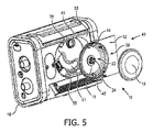
[29] 非限定的な例示として、図3は、ガスケット11及びフィルタ18を収容する本体部12の拡大図を示す。図4は、マフラーアセンブリ200(図2)の端部37から見た本体部12の図を示す。図5は、本体部12及びフィルタ18と圧力発生器16との結合を示す。図4において図示されるように、着座プレート35は、ネジ83及び/又は他の結合メカニズムを介して本体部12に結合される。図4及び図5において図示されるように、着座プレート35は、圧力発生器16における収容機構51(図5)に対応する着座機構49(図4)を含む。着座面39(図4)は、着座面39を受けるように構成された圧力発生器16の部分53(図5)に対応する。開口部45(図4及び図5)は、圧力発生器16における対応する機構55(例えば、ネジ山)に係合するネジ及び/又は他の結合コンポーネントを受ける。
[29] As a non-limiting example, FIG. 3 shows an enlarged view of the
[30] 図6は、本体部12に結合された支持体24を示す。支持体24は、(例えば、図2において図示されるように)本体部12からフィルタ18に向かって延在してフィルタ18を支持するように構成される。支持体24は、本体部12の開口部19及び/又は圧力発生器16(図1)の吸引口14(図1)内へのフィルタ18の陥没に抵抗する。開口部19(及び/又は吸引口14)内へのフィルタ18の陥没は、フィルタ18を通過して圧力発生器の吸引口14へと流れるガスによって、及び/又は他の力によって引き起こされる。支持体24は、開口部19及び吸引口14にわたる圧力降下を減少させるために開口部19を通過する自由な流動断面積を依然として実質的に最大化しつつ、フィルタ18の陥没を防止する。支持体24は、開口部19において又はその近くにおいて本体部12に結合される。いくつかの実施形態において、支持体24は突起であり、本体部12の第2の側面22からフィルタ18に向かって延在してフィルタ18を支持する。
[30] FIG. 6 shows a
[31] いくつかの実施形態において、支持体24は、3つの弓状部材32、34、36及び/又は他のコンポーネントを備える。いくつかの実施形態において、支持体24は、3つより多い又は3つより少ない弓状部材を備える。いくつかの実施形態において、支持体24は、1つ又は複数の非弓状部材を備える。いくつかの実施形態において、個々の弓状部材32、34及び/又は36は、本体部12の第2の側面22において又はその近くにおいて開口部19の縁部に結合された一端部と、本体部12の第2の側面22に対する突出位置59において他の弓状部材に結合された反対側端部とを有する。いくつかの実施形態において、開口部19は、中央軸61を有する円形状の断面を有し、弓状部材32、34及び/又は36の反対側端部は、突出位置59における、円形状の開口部19の中央軸61に対応する場所において結合される。例えば、図6において、突出位置59は中央軸61に沿っている。
[31] In some embodiments, the
[32] いくつかの実施形態において、弓状部材32、34及び/又は36の端部は、開口部19の周縁の周りの実質的に等距離な位置63、65、67及び/又は他の場所に位置付けられる。いくつかの実施形態において、開口部19は、最大で約1インチまでの直径を有する。いくつかの実施形態において、開口部19は、約0.5インチから約1インチの間の直径を有する。いくつかの実施形態において、開口部19は、約0.75インチの直径を有する。いくつかの実施形態において、弓状部材32、34及び/又は36は、支持体24がフィルタ18によって支持体24に及ぼされる力及び/又は他の力を支持することが可能であるように構成された幅91、厚さ93(図7)及び/又は位置63、65、67を有する。幅91、厚さ93及び/又は位置63、65、67は、支持体24を作成するために使用される材料、開口部19の直径、支持体24に及ぼされる力の大きさ及び/又は方向、及び/又は他の要因に依存する。
[32] In some embodiments, the ends of the
[33] いくつかの実施形態において、支持体24は、プラスチック射出成形、金属加工及び/又は金属製作、及び/又は他の方法の使用を含むがこれらに限定されない様々なやり方によって製造される。いくつかの実施形態において、支持体24は、接着剤、ネジ、ナット、ボルト、クリップ、クランプ、フック、及び/又は他の結合デバイス、スロット、溝、チャンネル及び/又は本体部12における他の表面機構、及び/又は他の結合コンポーネントなどの、結合コンポーネントを介して本体部12に結合される。いくつかの実施形態において、支持体24は本体部12と一体的である。非限定的な例示として、図6において図示される支持体24の例は、射出成形され、「バイパス」鋼が支持体24の機構(例えば、本明細書において説明されるもの)を生むために使用された。
[33] In some embodiments, the
[34] 図7は、本体部12及びフィルタ18の切り欠き図を示す。図7において図示されるように、着座プレート35は、封止リング81及び/又は他の結合メカニズムを介して本体部12に結合される。着座機構49は、開口部19から圧力発生器の吸引口14(図7においては不図示)にガスを誘導するように構成された流路を形成する。本体部12によって収容される(例えば、図7において示されるように、ガスケット11における対応する溝73、フィルタ18における位置合わせ機構75、及び/又は他のコンポーネントを介する)ことに応じて、パンケーキフィルタ18の第1の側面26は、本体部12の第2の側面22と係合する。いくつかの実施形態において、支持体24は、最大で約1インチまでの距離71だけ第2の側面22から延在する。いくつかの実施形態において、支持体24は、約0.5インチから約1インチの間の距離71だけ第2の側面22から延在する。いくつかの実施形態において、支持体24は、約0.68インチから約0.75インチの間の距離71だけ第2の側面22から延在する。支持体24は、パンケーキフィルタ18の第1の側面26を超えてパンケーキフィルタ18の内部28に延在し、パンケーキフィルタ18の反対側の第2の側面30を内部28から支持する。例えば、図7において図示されるように、支持体24は、側面30の内部が支持体24の突出位置59と係合するように構成される。
[34] FIG. 7 shows a notched view of the
[35] 開口部19の縁部における支持体24の本体部12に対する結合の説明、弓状部材32、34及び36によって形成される支持体24の説明、及び本明細書において説明される寸法は、限定を意図するものではない。支持体24は、任意の結合コンポーネントによって本体部12に結合されてよく、装置10が本明細書において説明されるように機能することを可能にする任意の形状を有してよい。支持体24は、任意の結合方法によって本体部12と結合されてよく、及び/又は、開口部19及び/又は圧力発生器16(図1)の吸引口14(図1)内へのフィルタ18の陥没を防止する任意の形状を有してよい。支持体24は、他の形状及び/又は結合方法によって、開口部19及び吸引口14にわたる圧力降下を減少させるために開口部19を通過する自由な流動断面積を依然として実質的に最大化しつつ、フィルタ18の陥没を防止してよい。寸法は、装置10が本明細書において説明されるように機能することを可能にする任意のサイズに拡大縮小されてよい。
[35] The description of the coupling of the
[36] 例えば、図8は、支持体24の別の実施形態を示す。図8において、支持体24は、開口部19の中央部分99にクリップされた単一の弓状コンポーネント97によって形成される。いくつかの実施形態において、中央部分99は、開口部19において支持体24を収容するように、本体部12の一部として形成され、及び/又は、中央部分99は、開口部19において及び/又はその近くにおいて本体部12に結合される。いくつかの実施形態において、弓状コンポーネント97は、図7において図示される支持体24の実施形態と同一の突出位置59へと延在する。いくつかの実施形態において、弓状コンポーネント97は、例えば、弓状コンポーネント97の特性(例えば、材料、厚さ、クリップメカニズムなど)及び/又は他の要因に応じて、異なる位置へと延在する。
[36] For example, FIG. 8 shows another embodiment of the
[37] 図9から図11は、支持体24(図2)がある状態及びない状態でのマフラーアセンブリ200(図2)におけるパンケーキフィルタ18(図2)の使用を示す。図9から図11は、圧力対流量のグラフにプロットされた圧力降下曲線によって、吸引口14(図1)における圧力降下を示す。図9は、パンケーキフィルタ18又は支持体24がマフラーアセンブリ200に設置されていない状態で(例えば、基準のために)測定された第1の圧力降下曲線101、及びパンケーキフィルタ18が設置されているが支持体24が設置されていない状態で測定された第2の圧力降下曲線103を示す。2つの曲線101と103との間には、(以下に説明される図10及び図11と比べて)大きな差異105があるが、これは、曲線103について行われた測定中にフィルタ18が開口部19(図2)及び/又は吸引口14内へと陥没しやすいからである。図10は、第1の圧力降下曲線101、第2の圧力降下曲線103、及びフィルタ18と第1の実施形態(例えば、図2から図7において示された実施形態)の支持体24とが設置された状態で測定された第3の圧力降下曲線107を示す。図10は、圧力降下の向上109を示すが、これは、フィルタ18が支持体24によって支持されたからである。図10において図示されるように、第1の実施形態の支持体24の設置によって、曲線101と107との間の差異111は、曲線101と103との間の差異105(図9)に比べて小さくなっている。図11は、第1の圧力降下曲線101、第2の圧力降下曲線103、及びフィルタ18と第2の実施形態(例えば、図8において示された実施形態)の支持体24とが設置された状態で測定された第4の圧力降下曲線113を示す。図10と同様に、図11は、圧力降下の向上115を示すが、これは、フィルタ18が支持体24によって支持されたからである。図11において図示されるように、第2の実施形態の支持体24の設置によって、曲線101と113との間の差異117は、曲線101と103との間の差異105(図9)に比べて小さくなっている。
[37] FIGS. 9-11 show the use of the pancake filter 18 (FIG. 2) in the muffler assembly 200 (FIG. 2) with and without the support 24 (FIG. 2). 9 to 11 show the pressure drop at the suction port 14 (FIG. 1) by the pressure drop curve plotted in the pressure vs. flow graph. FIG. 9 shows a first
[38] 図1に戻ると、圧力発生器16は、対象者50の気道への送達のためにガスの流れを生成するように構成される。圧力発生器16は、治療目的のため及び/又は他の目的のために、ガスの流れの1つ又は複数のパラメータ(例えば、流量、圧力、ボリューム、温度、ガス組成など)を制御する。非限定的な例示として、圧力発生器16は、対象者50の気道に対する圧力支援を提供するために、ガスの流れの流量及び/又は圧力を制御するように構成される。圧力発生器16は、吸引口14を通る周囲大気及び/又は他の源などのガス源からのガスの流れを受け入れ、対象者50の気道への送達のためにこのガスの圧力を上昇させる。圧力発生器16は、対象者50への送達のために受け入れたガスの圧力を上昇させることが可能な、例えば、ポンプ、送風機、ピストン、ふいご及び/又は他のデバイスなどの1つ又は複数のデバイスを備える。圧力発生器16は、ガスの圧力/流量を制御するために1つ又は複数のバルブを備えてよい。本開示は、患者に提供されるガスの圧力/流れを制御するために、圧力発生器16に含まれる送風機の動作速度を単独で又はこのようなバルブとの組合せによって制御することも企図する。
[38] Returning to FIG. 1, the
[39] ガス送達流路52は、圧力発生器16と対象者50との間でガスを伝達するように構成される。そのため、ガス送達流路52は、インタフェース器具54、1つ又は複数の導管56及び/又は他のコンポーネントを備える。1つ又は複数の導管56は、インタフェース器具54へとガスの圧流を運ぶように構成される。1つ又は複数の導管56は、柔軟な長さのホース、及び/又は圧力発生器16とインタフェース器具54との間でガスを伝達するように構成された他の導管を備える。インタフェース器具54は、対象者50の気道へとガスの流れを送達するように構成される。いくつかの実施形態において、インタフェース器具54は、対象者50の口及び/又は鼻によって非侵襲的に係合されるように構成される。非侵襲的係合は、対象者50の気道とインタフェース器具54との間でガスを伝達するために、対象者50の気道の1つ又は複数の外部開口(例えば、鼻孔及び/又は口)に取り外し可能に係合することを含む。非侵襲的インタフェース器具54のいくつかの例としては、例えば、鼻カニューレ、鼻マスク、鼻/口腔マスク、フルフェースマスク、全体フェースマスク、及び/又は対象者の気道とガスの流れを伝達する他のインタフェース器具などがある。いくつかの実施形態において、インタフェース器具54は、気管内チューブ又は他の侵襲的器具などの侵襲的器具を含む。本開示は、これらの例に限定されるものではなく、任意のインタフェース器具を使用した対象者へのガスの流れの送達を企図する。
[39] The
[40] 図1においてガス送達流路52は、対象者50の気道へのガスの送達のための単一リムのインタフェースとして示されているが、これは限定を意図するものではない。本開示の範囲は、対象者の気道にガスの流れを提供するように構成された第1のリムと、ガスを選択的に排出する(例えば、呼気ガスを排出する)ように構成された第2のリムとを有する二重リム回路を含む。このような第2のリムは、例えば、周囲大気にガスを排出し、及び/又はインタフェース器具54を圧力発生器16の吸引口14に結合する。
[40] In FIG. 1, the
[41] 1つ又は複数のシステムセンサ60は、システム8内のガスの1つ又は複数のパラメータに関する情報及び/又は他の情報を運ぶ出力信号を生成するように構成される。システム8内のガスの1つ又は複数のパラメータは、呼吸可能なガス圧流に関するガスパラメータ、対象者50の呼吸に関する呼吸パラメータ、及び/又は他のパラメータを含む。センサ60は、このようなパラメータを(例えば、インタフェース器具54におけるガスの流れとの流体連通を通じて)直接的に測定する1つ又は複数のセンサを備える。センサ60は、1つ又は複数のパラメータに関する代理出力信号を間接的に生成する1つ又は複数のセンサを備える。例えば、センサ60は、圧力発生器16の動作パラメータ(例えば、モータ電流からの流量及び/又は圧力の推定値、電圧、回転ベロシティ、及び/又は他の動作パラメータ)に基づいて出力を生成するように構成された1つ又は複数のセンサ、及び/又は他のセンサを備える。
[41] The
[42] 呼吸可能なガスの圧流の1つ又は複数のガスパラメータは、例えば、流量、ボリューム、圧力、湿度、温度、加速度、ベロシティ、ガスの化学的組成に関連する1つ又は複数のパラメータ、及び/又は他のガスパラメータのうちの1つ又は複数を含む。対象者50の呼吸に関する呼吸パラメータは、一回呼吸量、タイミング(例えば、吸気の開始及び/又は終了、並びに呼気の開始及び/又は終了など)、呼吸速度、期間(例えば、吸気、呼気、及び単一の呼吸サイクルの期間など)、呼吸数、及び/又は他の呼吸パラメータを含む。図1においてセンサ60はシステム8の1つの場所にのみ示されているが、これは限定を意図するものではない。例えば、センサ60は、圧力発生器16内及びインタフェース器具54内(又はこれと通信する)の様々な場所及び/又は他の場所などの複数の場所に配置されたセンサを備えてよい。
[42] One or more gas parameters of the pressure flow of a breathable gas may be, for example, one or more parameters related to flow rate, volume, pressure, humidity, temperature, acceleration, velocity, chemical composition of the gas. And / or includes one or more of other gas parameters. Respiratory parameters for the subject 50's breathing include one-time breathing volume, timing (eg, start and / or end of inspiration, and start and / or end of exhalation, etc.), respiratory rate, duration (eg, inspiration, exhalation, and exhalation). Includes (such as the duration of a single breathing cycle), breathing rate, and / or other breathing parameters. Although the
[43] コントローラ70は、圧力支援治療法及び/又は他の治療法に従ってガスの流れを生成するように圧力発生器16を制御するように構成される。いくつかの実施形態において、圧力発生器16によって生成されたガスの圧流は、患者の通常の呼吸に取って代わるように、及び/又は患者の通常の呼吸を補完するように制御される。圧力支援治療は、患者からの努力を僅かしか必要とせず及び/又は患者からの努力を必要とせずに酸素及び二酸化炭素がより容易に交換されるように、患者の開いた気道を維持するために使用される。非限定的な例示として、コントローラ70は、対象者に対してガスの流れを介して提供される圧力支援が、連続的気道陽圧(CPAP:continuous positive airway pressure)支援、二相性気道陽圧(BPAP:bi-level positive airway pressure)支援、比例気道陽圧(PPAP:proportional positive airway pressure)支援、強制振動技術、及び/又は他のタイプの圧力支援治療を含むように圧力発生器16を制御する。
[43] The
[44] CPAPは、患者における気道陽圧の連続的なレベルを維持するために一定の陽圧を供給する。BPAPは、第1の吸気圧(IPAP:inspiratory pressure)及び換気中のより容易な呼気のために典型的にはこれより低い第2の呼気圧(EPAP:expiratory pressure)を提供する。いくつかの治療モード(例えば、PPAP)において、コントローラ70は、吸気の期間及び/又は呼気の期間中に患者に対して提供される圧力の量が呼吸ごとに決定されて提供されるような可変的な圧力支援を与えるように圧力発生器16を制御する。いくつかの実施形態において、コントローラ70は、患者に必要とされる呼気のための努力を減少させるために、呼気(C-FLex)の期間中に提供される圧力を一時的に降下させるように圧力発生器16を制御するように構成される。いくつかの実施形態において、コントローラ70は、段階的な圧力支援を提供するように圧力発生器16を制御するように構成される。段階的な圧力支援治療において、圧力発生器16によって提供される圧力は、時間とともに徐々に増加する。いくつかの実施形態において、コントローラ70は、対象者50の呼吸に関する情報及び/又は他の情報に基づいて治療モードを切り替えるように圧力発生器16を制御する。例えば、コントローラ70は、対象者50による特定の回数の呼吸の後、BPAPからCPAPに変更するように圧力発生器16を制御する。コントローラ70は、センサ60からの出力信号によって運ばれる情報、ユーザによってユーザインタフェース90に入力された情報、電子記憶装置80に記憶された情報、及び/又は他の情報に基づいて圧力発生器16を制御するように構成される。
[44] CPAP supplies a constant positive pressure to maintain continuous levels of positive airway pressure in the patient. BPAP provides a first inspiratory pressure (IPAP) and a second expiratory pressure (EPAP) typically lower for easier exhalation during ventilation. In some modes of treatment (eg PPAP), the
[45] ユーザインタフェース90は、システム8と対象者50及び/又は他のユーザとの間のインタフェースを提供するように構成され、これを通じて対象者50及び/又は他のユーザはシステム8に情報を提供し、システム8から情報を受け取る。他のユーザには、例えば、介護者、医師、及び/又は他のユーザが含まれる。これは、データ、キュー、結果及び/又は命令並びに集合的に「情報」と称される任意の他の通信可能なアイテムが、ユーザ(例えば対象者50)と、圧力発生器16、コントローラ70及び/又はシステム8の他のコンポーネントのうちの1つ又は複数との間で通信されることを可能にする。例えば、ユーザは、ユーザインタフェース90を使用して、対象者50に提供されるべき1つ又は複数の治療法を指定する。次いで、コントローラ70は、対象者50に提供される治療法を、ユーザによってユーザインタフェースに対して行われた1つ又は複数の入力に基づいてカスタマイズする。別の例として、治療圧力、対象者50の呼吸速度及び/又は他の情報は、ユーザインタフェース90を介してユーザ(例えば、対象者50)に対して表示される。
[45] The
[46] ユーザインタフェース90に含まれるのに適したインタフェースデバイスの例としては、キーパッド、ボタン、スイッチ、キーボード、ノブ、レバー、表示スクリーン、タッチスクリーン、スピーカ、マイクロホン、インジケータライト、可聴アラーム、プリンタ、触覚フィードバックデバイス及び/又は他のインタフェースデバイスなどがある。一実施形態において、ユーザインタフェース90は、複数の別個のインタフェースを含む。一実施形態において、ユーザインタフェース90は、圧力発生器16及び/又はコントローラ70と一体的に提供された少なくとも1つのインタフェースを含む。
[46] Examples of suitable interface devices included in the
[47] 配線で接続されたもの又は無線の他の通信技術も、本開示によってユーザインタフェース90として企図されることを理解されたい。例えば、本開示は、ユーザインタフェース90は、電子記憶装置80によって提供される取り外し可能な記憶装置インタフェースと一体化されることを企図する。この例においては、情報は、ユーザがシステム8の実施態様をカスタマイズすることを可能にする取り外し可能な記憶装置(例えば、スマートカード、フラッシュドライブ、取り外し可能ディスクなど)からシステム8にロードされる。ユーザインタフェース90としてシステム8とともに使用されることに適合された他の例示的な入力デバイス及び技術としては、これらに限定されるものではないが、RS-232ポート、RFリンク、IRリンク、モデム(電話機、ケーブルなど)などがある。端的に言えば、システム8と情報を通信する任意の技術が、本開示によってユーザインタフェース90として企図される。
[47] It should be understood that other wiring-connected or wireless communication techniques are also contemplated as the
[48] いくつかの実施形態において、電子記憶装置80は、情報を電子的に記憶する電子記憶媒体を備える。電子記憶装置80の電子記憶媒体は、システム8と一体的に(すなわち、実質的に取り外し不可能に)提供されるシステム記憶装置、及び/又は、例えば、ポート(例えば、USBポート、ファイヤワイヤポートなど)又はドライブ(例えば、ディスクドライブなど)を介してシステム8に取り外し可能に接続可能な取り外し可能記憶装置のうちの一方又は両方を備える。電子記憶装置80は、光学的読み取り可能記憶媒体(例えば、光学的ディスクなど)、磁気的読み取り可能記憶媒体(例えば、磁気テープ、磁気的ハードドライブ、フロッピードライブなど)、電荷ベースの記憶媒体(例えば、EEPROM、RAMなど)、固体記憶媒体(例えば、フラッシュドライブなど)及び/又は他の電子的に読み取り可能な記憶媒体のうちの1つ又は複数を備える。電子記憶装置80は、ソフトウェアアルゴリズム、コントローラ70によって決定された情報、ユーザインタフェース90を介して受信された情報及び/又はシステム8が適切に動作することを可能にする他の情報を記憶する。電子記憶装置80は、(全体的に又は部分的に)システム8内の別個のコンポーネントであってよく、又は、電子記憶装置80は、システム8の1つ又は複数の他のコンポーネント(例えば、ユーザインタフェース90、コントローラ70、圧力発生器16など)と(全体的に又は部分的に)一体的に提供されてよい。
[48] In some embodiments, the
[49] コントローラ70によって決定された情報及び/又は電子記憶装置80によって記憶された情報は、対象者50の呼吸に関する情報、コンプライアンス、使用頻度及び/又は他の情報を含む。電子記憶装置80によって記憶された情報は、ユーザインタフェース90を介して、及び/又は他の方法を介して閲覧される。電子記憶装置80によって記憶された情報は、例えば、設定を調節するために、医師が医療的決定を行うために、及び/又は他の用途のために使用される。いくつかの実施形態において、システム8は、無線送信機(不図示)を含み、コントローラ70によって決定された情報、電子記憶装置80によって記憶された情報及び/又は他の情報は、例えば、無線ネットワークを通じて介護者に通信される。
[49] The information determined by the
[50] 図12は、圧力発生器用吸引口装置によって圧力発生器内に引き入れられたガスをフィルタリングするための方法1200を示す。吸引口装置は、本体部、支持体及び/又は他のコンポーネントを備える。以下に提示される方法1200の動作は、例示的なものであると意図される。いくつかの実施形態において、方法1200は、説明されていない1つ又は複数の追加的な動作によって達成され、及び/又は、論じられている動作のうちの1つ又は複数がなくても達成される。加えて、図12において方法1200の動作が示され、以下において説明される順番は、限定を意図するものではない。 [50] FIG. 12 shows a method 1200 for filtering gas drawn into a pressure generator by a pressure generator suction port device. The suction port device comprises a body, a support and / or other components. The behavior of method 1200 presented below is intended to be exemplary. In some embodiments, method 1200 is accomplished by one or more additional actions not described and / or without one or more of the actions discussed. To. In addition, the operation of method 1200 is shown in FIG. 12 and the order described below is not intended to be limiting.
[51] 動作1202において、圧力発生器の吸引口は、圧力発生器用吸引口装置の本体部に取り外し可能に係合される。動作1202において、本体部は粒子フィルタを収容する。本体部は、圧力発生器の吸引口へとフィルタを通過したガスを誘導するように構成された開口部を形成する。いくつかの実施形態において、フィルタは両面ディスクフィルタである。いくつかの実施形態において、両面ディスクフィルタはパンケーキフィルタである。いくつかの実施形態において、本体部は、本体部の第1の側面において吸引口に結合し、本体部の第1の側面の反対側の第2の側面においてフィルタを収容する。いくつかの実施形態において、動作1202は、(図2において図示され、本明細書において説明される)本体部12と同一の又は類似の本体部によって行われる。
[51] In
[52] 動作1204において、支持体は、本体部に結合される。支持体は、開口部において又はその近くにおいて本体部に結合される。支持体は、本体部からフィルタに向かって延在してフィルタを支持するように構成される。支持体は、フィルタを通過して圧力発生器の吸引口へと流れるガスによって引き起こされる本体部の開口部内へのフィルタの陥没に抵抗する。いくつかの実施形態において、支持体は突起であり、突起は、本体部の第2の側面からフィルタに向かって延在してフィルタを支持する。いくつかの実施形態において、本体部によって収容されることに応じて、パンケーキフィルタの第1の側面は、本体部の第2の側面に係合し、突起は、パンケーキフィルタの第1の側面を越えてパンケーキフィルタの内部に延在し、パンケーキフィルタの反対側の第2の側面を内部から支持する。
[52] In
[53] いくつかの実施形態において、突起は、3つの弓状部材及び/又は他のコンポーネントを備える。個々の弓状部材は、本体部の第2の側面において又はその近くにおいて開口部の縁部に結合された一端部と、本体部の第2の側面に対する突出位置において他の弓状部材に結合された反対側端部とを有する。いくつかの実施形態において、開口部は、中央軸を有する円形状の断面を有し、弓状部材の反対側端部は、突出位置における、円形状の開口部の中央軸に対応する場所において結合される。いくつかの実施形態において、動作1204は、(図2において図示され、本明細書において説明される)支持体24と同一の又は類似の支持体によって行われる。
[53] In some embodiments, the protrusion comprises three arched members and / or other components. The individual arched members are coupled to one end of the body at or near the edge of the opening and to the other arched member at a protruding position with respect to the second side of the body. Has a contralateral end. In some embodiments, the opening has a circular cross section with a central axis, and the opposite end of the arched member is in the protruding position, at a location corresponding to the central axis of the circular opening. Be combined. In some embodiments,
[54] 特許請求の範囲において、括弧の間に置かれた任意の参照符号は、請求項を限定するものと解釈されるべきではない。「備える」又は「含む」という語は、請求項に列記されたもの以外の要素又はステップの存在を排除するものではない。いくつかの手段を列挙するデバイスの請求項において、これらの手段のうちのいくつかは、1つの同一のハードウェアアイテムによって具現化され得る。ある要素に先行する「1つの(a又はan)」という語は、そのような要素が複数存在することを排除するものではない。いくつかの手段を列挙する任意のデバイスの請求項において、これらの手段のうちのいくつかは、1つの同一のハードウェアアイテムによって具現化され得る。特定の要素が互いに異なる従属請求項に記載されるという単なる事実は、これらの要素が組み合わされて使用され得ないことを示すものではない。 [54] In the claims, any reference code placed between parentheses should not be construed as limiting the claim. The word "preparing" or "including" does not preclude the existence of elements or steps other than those listed in the claims. In a device claim enumerating several means, some of these means may be embodied by one and the same hardware item. The word "one (a or an)" preceding an element does not preclude the existence of multiple such elements. In any device claim that enumerates several means, some of these means may be embodied by one and the same hardware item. The mere fact that certain elements are described in different dependent claims does not indicate that these elements cannot be used in combination.
[55] 上に提供された説明は、現在のところ最も実際的で好ましいと考えられる実施形態に基づいて例示を目的として詳細を提供したが、そのような詳細は、その目的のためだけのものであり、本開示は、明確に開示された実施形態に限定されるものではなく、それどころか、添付の特許請求の範囲の精神及び範囲内にある修正及び等価な構成をカバーするものと意図されることを理解されたい。例えば、本開示は、可能な限り、任意の実施形態の1つ又は複数の特徴が、任意の他の実施形態の1つ又は複数の特徴と組み合わされ得ることを企図することを理解されたい。
[55] The description provided above has provided details for illustration purposes based on embodiments currently considered to be the most practical and preferred, but such details are solely for that purpose. And the present disclosure is not limited to the expressly disclosed embodiments, but is intended to cover amendments and equivalent configurations within the spirit and scope of the appended claims. Please understand that. For example, it should be understood that the present disclosure contemplates, wherever possible, one or more features of any embodiment may be combined with one or more features of any other embodiment.
Claims (8)
前記開口部において又はその近くにおいて前記本体部に結合された支持体であって、前記支持体は、前記本体部から前記粒子フィルタに向かって延在して前記粒子フィルタを支持し、前記支持体は、前記粒子フィルタを通過して前記圧力発生器の吸引口へと流れるガスによって引き起こされる前記開口部内への前記粒子フィルタの陥没に抵抗するように構成される、支持体と
を備える、圧力発生器用吸引口装置であって、
前記本体部は、前記本体部の第1の側面において前記吸引口に結合し、前記本体部の前記第1の側面の反対側の、前記本体部の第2の側面において前記粒子フィルタの第1の側面を収容し、
前記支持体は突起であり、前記突起は、前記本体部の前記第2の側面から前記粒子フィルタの前記第1の側面を通って延在し、前記粒子フィルタの第2の反対側面に係合することによって前記粒子フィルタの陥没に抵抗する、
圧力発生器用吸引口装置。 A main body that is detachably engaged with the suction port of the pressure generator to accommodate the particle filter of the double-sided disc, and the main body is a gas that has passed through the particle filter to the suction port of the pressure generator. The main body, which forms the opening to guide,
A support coupled to the main body at or near the opening, the support extending from the main body toward the particle filter to support the particle filter and supporting the support. Includes a support configured to resist the depression of the particle filter into the opening caused by the gas flowing through the particle filter and into the suction port of the pressure generator. It is a dexterous suction port device,
The main body is coupled to the suction port on the first side surface of the main body, and the first of the particle filters is on the second side surface of the main body opposite to the first side surface of the main body. Accommodates the sides of
The support is a protrusion that extends from the second side of the body through the first side of the particle filter and engages the second opposite side of the particle filter. By doing so, it resists the depression of the particle filter.
Suction port device for pressure generator.
前記粒子フィルタを支持する手段であって、前記支持する手段は、前記開口部において又はその近くにおいて前記係合して粒子フィルタを収容する手段に結合され、前記支持する手段は、前記係合して粒子フィルタを収容する手段から前記粒子フィルタに向かって延在して前記粒子フィルタを支持し、前記粒子フィルタを通過して前記圧力発生器の吸引口へと流れるガスによって引き起こされる前記開口部内への前記粒子フィルタの陥没に抵抗するように構成される、前記支持する手段と
を備え、
前記係合して粒子フィルタを収容する手段は、前記係合して粒子フィルタを収容する手段の第1の側面において前記吸引口に結合し、前記係合して粒子フィルタを収容する手段の前記第1の側面の反対側の、前記係合して粒子フィルタを収容する手段の第2の側面において前記粒子フィルタの第1の側面を収容する、圧力発生器用吸引口装置であって、
前記支持する手段は突起を含み、前記突起は、前記係合して粒子フィルタを収容する手段の前記第2の側面から前記粒子フィルタの前記第1の側面を通って延在し、前記粒子フィルタの第2の反対側面に係合することによって前記粒子フィルタの陥没に抵抗する、圧力発生器用吸引口装置。 A means for detachably engaging with the suction port of the pressure generator to accommodate the particle filter of the double-sided disk, and forming an opening for guiding the gas passing through the particle filter to the suction port of the pressure generator. The means for engaging and accommodating the particle filter,
The means for supporting the particle filter, wherein the supporting means is coupled to the engaging means for accommodating the particle filter at or near the opening, and the supporting means is the engaging means. Into the opening caused by the gas extending from the means accommodating the particle filter toward the particle filter to support the particle filter and flowing through the particle filter to the suction port of the pressure generator. With said supporting means configured to resist the depression of said particle filter.
The means for accommodating the engaged particle filter is the means for engaging and accommodating the particle filter, which is coupled to the suction port on the first side surface of the means for accommodating the engaged particle filter. A suction port device for a pressure generator, which accommodates the first side surface of the particle filter on the second side surface of the means for accommodating the engaged particle filter on the opposite side of the first side surface.
The supporting means comprises a protrusion, which extends from the second side of the engaging means for accommodating the particle filter through the first side of the particle filter and the particle filter. A suction port device for a pressure generator that resists the depression of the particle filter by engaging with the second opposite side surface of the particle filter.
Applications Claiming Priority (3)
| Application Number | Priority Date | Filing Date | Title |
|---|---|---|---|
| US201662430970P | 2016-12-07 | 2016-12-07 | |
| US62/430,970 | 2016-12-07 | ||
| PCT/EP2017/081797 WO2018104437A1 (en) | 2016-12-07 | 2017-12-07 | Pressure generator inlet filter apparatus |
Publications (3)
| Publication Number | Publication Date |
|---|---|
| JP2020500621A JP2020500621A (en) | 2020-01-16 |
| JP2020500621A5 JP2020500621A5 (en) | 2021-01-21 |
| JP7090613B2 true JP7090613B2 (en) | 2022-06-24 |
Family
ID=60582607
Family Applications (1)
| Application Number | Title | Priority Date | Filing Date |
|---|---|---|---|
| JP2019530073A Active JP7090613B2 (en) | 2016-12-07 | 2017-12-07 | Suction port filter device for pressure generator |
Country Status (4)
| Country | Link |
|---|---|
| US (1) | US11623055B2 (en) |
| EP (1) | EP3551269B1 (en) |
| JP (1) | JP7090613B2 (en) |
| WO (1) | WO2018104437A1 (en) |
Families Citing this family (2)
| Publication number | Priority date | Publication date | Assignee | Title |
|---|---|---|---|---|
| US11883690B2 (en) * | 2019-11-04 | 2024-01-30 | Koninklijke Philips N.V. | Multi-directional filtration arrangement, flow generating device and system including same |
| WO2023219665A1 (en) * | 2022-05-11 | 2023-11-16 | Watt Fuel Cell Corp. | Blower filter assembly |
Citations (2)
| Publication number | Priority date | Publication date | Assignee | Title |
|---|---|---|---|---|
| JP2013501541A (en) | 2009-08-11 | 2013-01-17 | レスメド・モーター・テクノロジーズ・インコーポレーテッド | Single stage, axisymmetric blower and portable ventilator |
| JP2014508594A (en) | 2011-02-25 | 2014-04-10 | レスメド・モーター・テクノロジーズ・インコーポレーテッド | Blower and PAP system |
Family Cites Families (24)
| Publication number | Priority date | Publication date | Assignee | Title |
|---|---|---|---|---|
| US2201650A (en) * | 1936-12-14 | 1940-05-21 | United Specialties Co | Air cleaner |
| US2959247A (en) | 1958-10-31 | 1960-11-08 | W W Sly Mfg Company | Filter bag |
| US3339533A (en) * | 1967-01-26 | 1967-09-05 | Nordstrom Per Ingemar | Air filter for internal combustion engines |
| US3686837A (en) * | 1969-02-07 | 1972-08-29 | Walker Mfg Co | Dual media air filter |
| US3681898A (en) * | 1970-07-27 | 1972-08-08 | Tenneco Inc | Dual media air filter |
| BE788211A (en) * | 1971-09-16 | 1973-02-28 | Pall Corp | DEVICE AVAILABLE FOR FILTERING GAS |
| US3884658A (en) * | 1972-04-18 | 1975-05-20 | Pall Corp | Air cleaner for supercharged engines |
| US4199334A (en) * | 1978-05-26 | 1980-04-22 | Donaldson Company, Inc. | Self-cleaning air filter |
| AT365090B (en) * | 1980-04-16 | 1981-12-10 | Inkomag | FILTRATION DEVICE |
| US4543112A (en) * | 1984-04-30 | 1985-09-24 | Figgie International Inc. | Sorbent type filter assembly for a respirator and method of making same |
| US4548626A (en) * | 1984-04-30 | 1985-10-22 | Figgie International Inc. | Particulate air filter assembly |
| GB2195545B (en) * | 1985-05-04 | 1989-02-08 | Protector Safety Ltd | Respirators |
| CH679122A5 (en) * | 1989-09-29 | 1991-12-31 | Micronel Ag | |
| JP2720286B2 (en) | 1994-01-06 | 1998-03-04 | 株式会社エッチ・ケー・エス | Air cleaner device |
| CN101850147B (en) * | 2003-06-10 | 2012-11-21 | 雷斯梅德有限公司 | Multiple stage blower and enclosure therefor |
| US7419526B2 (en) * | 2005-03-03 | 2008-09-02 | 3M Innovative Properties Company | Conformal filter cartridges and methods |
| JP4378331B2 (en) | 2005-08-25 | 2009-12-02 | 株式会社ニフコ | Fuel filter device |
| US20090223368A1 (en) | 2008-03-07 | 2009-09-10 | Augustine Biomedical And Design, Llc | Distal hose end filter |
| US8070848B2 (en) | 2008-09-23 | 2011-12-06 | General Electric Company | Air filter mounting system and method for fabricating the same |
| AU2012207222B2 (en) | 2011-01-20 | 2016-07-14 | Scott Technologies, Inc. | Low profile frame for a filter incorporating a negative pressure check mechanism |
| JP2016528036A (en) * | 2013-08-02 | 2016-09-15 | オールタナティブ フュエル コンテイナーズ、エル・エル・シーAlternative Fuel Containers, Llc | Fuel gas pre-filter unit for vehicles |
| JP2015217750A (en) | 2014-05-15 | 2015-12-07 | 株式会社デンソー | Ventilation unit of air conditioner for vehicle |
| DE102015002052A1 (en) | 2015-02-16 | 2016-08-18 | Weinmann Emergency Medical Technology Gmbh + Co. Kg | Filter and device for ventilation with filter |
| CN205478403U (en) | 2016-01-15 | 2016-08-17 | 深圳市联创科技集团有限公司 | Electric fan capable of purifying air |
-
2017
- 2017-12-07 EP EP17809312.6A patent/EP3551269B1/en active Active
- 2017-12-07 JP JP2019530073A patent/JP7090613B2/en active Active
- 2017-12-07 US US16/465,369 patent/US11623055B2/en active Active
- 2017-12-07 WO PCT/EP2017/081797 patent/WO2018104437A1/en unknown
Patent Citations (2)
| Publication number | Priority date | Publication date | Assignee | Title |
|---|---|---|---|---|
| JP2013501541A (en) | 2009-08-11 | 2013-01-17 | レスメド・モーター・テクノロジーズ・インコーポレーテッド | Single stage, axisymmetric blower and portable ventilator |
| JP2014508594A (en) | 2011-02-25 | 2014-04-10 | レスメド・モーター・テクノロジーズ・インコーポレーテッド | Blower and PAP system |
Also Published As
| Publication number | Publication date |
|---|---|
| JP2020500621A (en) | 2020-01-16 |
| US20190388633A1 (en) | 2019-12-26 |
| US11623055B2 (en) | 2023-04-11 |
| WO2018104437A1 (en) | 2018-06-14 |
| EP3551269A1 (en) | 2019-10-16 |
| EP3551269B1 (en) | 2022-08-17 |
Similar Documents
| Publication | Publication Date | Title |
|---|---|---|
| US10166360B2 (en) | System and method for controlling flow during exhalation in a respiratory support system | |
| JP6175056B2 (en) | System and method for limited flow respiratory therapy | |
| NZ586099A (en) | Patient interface assembly comprising a jet pump including a venturi assembly defining an entrainment region, a throat region and an expansion region | |
| JP6288861B2 (en) | System and method for pressure-assisted therapy with shaped airflow | |
| JP6408464B2 (en) | System and method for improved compliance with respiratory therapy | |
| EP3209357B1 (en) | System for controlling leak | |
| WO2016103116A1 (en) | Secretion loosening and cough segmenting therapy | |
| JP7090613B2 (en) | Suction port filter device for pressure generator | |
| EP3880283B1 (en) | Pressure support system valve | |
| US11147939B2 (en) | Compact dual limb diaphragm valve system and method | |
| US20150306325A1 (en) | System for providing pressure pulses to the airway of a subject | |
| US11052207B2 (en) | Gas sensing apparatus | |
| US10881821B2 (en) | Mechanical ventilation based on alveolar ventilation |
Legal Events
| Date | Code | Title | Description |
|---|---|---|---|
| A521 | Request for written amendment filed |
Free format text: JAPANESE INTERMEDIATE CODE: A523 Effective date: 20201204 |
|
| A621 | Written request for application examination |
Free format text: JAPANESE INTERMEDIATE CODE: A621 Effective date: 20201204 |
|
| A977 | Report on retrieval |
Free format text: JAPANESE INTERMEDIATE CODE: A971007 Effective date: 20211022 |
|
| A131 | Notification of reasons for refusal |
Free format text: JAPANESE INTERMEDIATE CODE: A131 Effective date: 20211029 |
|
| A521 | Request for written amendment filed |
Free format text: JAPANESE INTERMEDIATE CODE: A523 Effective date: 20220120 |
|
| TRDD | Decision of grant or rejection written | ||
| A01 | Written decision to grant a patent or to grant a registration (utility model) |
Free format text: JAPANESE INTERMEDIATE CODE: A01 Effective date: 20220517 |
|
| A61 | First payment of annual fees (during grant procedure) |
Free format text: JAPANESE INTERMEDIATE CODE: A61 Effective date: 20220614 |
|
| R150 | Certificate of patent or registration of utility model |
Ref document number: 7090613 Country of ref document: JP Free format text: JAPANESE INTERMEDIATE CODE: R150 |