以下、添付図面に従って本開示の技術に係る実施形態の一例について説明する。
Hereinafter, an example of an embodiment according to the technique of the present disclosure will be described with reference to the accompanying drawings.
先ず、以下の説明で使用される用語の意味について説明する。以下の説明において、MEMSとは、“Micro Electro Mechanical Systems”の略称を指す。また、以下の説明において、I/Fとは、“Interface”の略称を指す。また、以下の説明において、I/Oとは、インプット・アウトプット・インタフェースの略称を指す。また、以下の説明において、USBとは、“universal serial bus”の略称を指す。また、以下の説明において、IDとは、“IDentification”の略称を指す。
First, the meanings of the terms used in the following description will be described. In the following description, MEMS refers to an abbreviation for "Micro Electro Electro Mechanical Systems". Further, in the following description, the I / F refers to the abbreviation of "Interface". Further, in the following description, I / O refers to an abbreviation for an input / output interface. Further, in the following description, USB refers to an abbreviation for "universal serial bus". Further, in the following description, the ID refers to the abbreviation of "IDentification".
また、以下の説明において、CPUとは、“Central Processing Unit”の略称を指す。また、以下の説明において、RAMとは、“Random Access Memory”の略称を指す。また、以下の説明において、HDDとは、“Hard Disk Drive”の略称を指す。また、以下の説明において、EEPROMとは、“Electrically Erasable and Programmable Read Only Memory”の略称を指す。また、以下の説明において、SSDとは、“Solid State Drive”の略称を指す。また、以下の説明において、DVD-ROMとは、“Digital Versatile Disc Read Only Memory”の略称を指す。
Further, in the following description, the CPU refers to an abbreviation of "Central Processing Unit". Further, in the following description, RAM refers to an abbreviation of "Random Access Memory". Further, in the following description, HDD refers to an abbreviation of "Hard Disk Drive". Further, in the following description, EEPROM refers to an abbreviation of "Electrically Erasable and Programmable Read Only Memory". Further, in the following description, SSD refers to the abbreviation of "Solid State Drive". Further, in the following description, DVD-ROM refers to an abbreviation of "Digital Versail Disc Read Only Memory".
また、以下の説明において、ASICとは、“Application Specific Integrated Circuit”の略称を指す。また、以下の説明において、FPGAとは、“Field-Programmable Gate Array”の略称を指す。また、以下の説明において、“PLD”とは、“Programmable Logic Device”の略称を指す。また、以下の説明において、LANとは、“Local Area Network”の略称を指す。
Further, in the following description, ASIC refers to an abbreviation for "Application Specific Integrated Circuit". Further, in the following description, FPGA refers to an abbreviation of "Field-Programmable Gate Array". Further, in the following description, "PLD" refers to an abbreviation for "Programmable Logic Device". Further, in the following description, LAN refers to an abbreviation of "Local Area Network".
また、本実施形態において、左右方向とは、例えば、患者の右眼の瞳孔の中心と左眼の瞳孔の中心とを通る直線の方向を指す。なお、以下では、説明の便宜上、「左右方向」を「X方向」とも称し、被検眼の瞳孔の中心から被検眼の後極に向かう方向を「Z方向」と称し、X方向及びZ方向の双方に対して垂直な方向を「Y方向」と称する。
Further, in the present embodiment, the left-right direction refers to, for example, the direction of a straight line passing through the center of the pupil of the right eye and the center of the pupil of the left eye of the patient. In the following, for convenience of explanation, the "left-right direction" is also referred to as the "X direction", and the direction from the center of the pupil of the eye to be inspected toward the posterior pole of the inspected eye is referred to as the "Z direction" in the X direction and the Z direction. The direction perpendicular to both is referred to as "Y direction".
[第1実施形態]
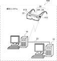
一例として図1に示すように、眼科システム10は、患者に対する視野の検査(以下、単に「視野検査」と称する)に供するシステムである。本実施形態では、視野検査が、患者(被検者)の被検眼の網膜にレーザ光を照射することで実現される。なお、レーザ光は、本開示の技術に係る「光源からの光」及び「視野検査に用いられる光源に基づく光である視野検査光」の一例である。[First Embodiment]
As shown in FIG. 1 as an example, the ophthalmic system 10 is a system used for a visual field examination (hereinafter, simply referred to as "visual field examination") for a patient. In the present embodiment, the visual field test is realized by irradiating the retina of the eye to be inspected of the patient (subject) with a laser beam. The laser beam is an example of "light from a light source" and "visual field inspection light which is light based on a light source used for visual field inspection" according to the technique of the present disclosure.
眼科システム10は、複数台のウエアラブル端末装置12と、管理装置14と、サーバ装置15と、ビューワ17と、を含む。なお、ウエアラブル端末装置12は、本開示の技術に係る眼科機器及びウエアラブル型眼科機器の一例である。
The ophthalmic system 10 includes a plurality of wearable terminal devices 12, a management device 14, a server device 15, and a viewer 17. The wearable terminal device 12 is an example of an ophthalmic device and a wearable ophthalmic device according to the technique of the present disclosure.
ウエアラブル端末装置12は、本開示の技術に係るアイウエア端末の一例であるアイウエア端末装置16、制御装置18、及び光分岐部20を含む。
The wearable terminal device 12 includes an eyewear terminal device 16, a control device 18, and an optical branching portion 20, which are examples of eyewear terminals according to the technique of the present disclosure.
アイウエア端末装置16は、患者に装着される眼鏡型の端末装置の一種である。ここで言う「患者」とは、眼底に疾患を有する患者を指す。なお、患者は、本開示の技術に係る被検者の一例である。
The eyewear terminal device 16 is a kind of eyeglass-type terminal device worn by a patient. The term "patient" as used herein refers to a patient having a disease in the fundus. The patient is an example of a subject according to the technique of the present disclosure.
アイウエア端末装置16は、一般的な眼鏡と同様に、リム22及びテンプル24を備えている。また、アイウエア端末装置16は、光学系27を備えている。
The eyewear terminal device 16 includes a rim 22 and a temple 24 like general eyeglasses. Further, the eyewear terminal device 16 includes an optical system 27.
リム22は、光学系27を保持している。テンプル24は、左側テンプル24Lと右側テンプル24Rとに大別される。左側テンプル24Lの一端部は、リム22の左端部に取り付けられており、右側テンプル24Rは、リム22の右端部に取り付けられている。
The rim 22 holds the optical system 27. The temple 24 is roughly classified into a left temple 24L and a right temple 24R. One end of the left temple 24L is attached to the left end of the rim 22, and the right temple 24R is attached to the right end of the rim 22.
左側テンプル24Lは、耳掛け部24L1を有する。右側テンプル24Rは、耳掛け部24R1を有する。耳掛け部24L1は、患者の左耳に掛けられ、耳掛け部24R1は、患者の右耳に掛けられる。
The left temple 24L has an ear hook portion 24L1. The right temple 24R has an ear hook 24R1. The ear hook 24L1 is hung on the patient's left ear, and the ear hook 24R1 is hung on the patient's right ear.
耳掛け部24L1には、スピーカ140が設けられている。スピーカ140は、制御装置18の制御下で、音声を出力する。スピーカ140は、患者の鼓膜に音波を直接当てるスピーカであってもよいし、振動を患者の鼓膜に間接的に伝達する骨伝導式のスピーカであってもよい。なお、スピーカ140は、患者の聴覚に働きかけることで患者に情報を通知する通知部の一例である。
The ear hook portion 24L1 is provided with a speaker 140. The speaker 140 outputs sound under the control of the control device 18. The speaker 140 may be a speaker that directly applies sound waves to the eardrum of the patient, or may be a bone conduction type speaker that indirectly transmits vibration to the eardrum of the patient. The speaker 140 is an example of a notification unit that notifies the patient of information by acting on the hearing of the patient.
制御装置18は、例えば、患者が把持したり、患者が自身の衣服又は身体等に装着したりして用いられる。制御装置18は、応答ボタン19を備えている。なお、応答ボタン19は、本開示の技術に係る応答部の一例である。ここでは、応答ボタン19を例示しているが、本開示の技術はこれに限定されない。例えば、応答ボタン19に代えてタッチパネルを用いてもよいし、患者がレーザ光を知覚したことに応答する場合の患者の音声をマイクで取得し、マイクで取得した音声を認識する音声認識装置を用いてもよい。この場合、タッチパネル及び音声認識装置は、患者からの働きかけに応じて、後述する応答情報を出力する。
The control device 18 is used, for example, by being grasped by the patient or worn by the patient on his / her clothes or body. The control device 18 includes a response button 19. The response button 19 is an example of a response unit according to the technique of the present disclosure. Although the response button 19 is illustrated here, the technique of the present disclosure is not limited to this. For example, a touch panel may be used instead of the response button 19, or a voice recognition device that acquires the patient's voice when the patient perceives the laser beam with a microphone and recognizes the voice acquired by the microphone. You may use it. In this case, the touch panel and the voice recognition device output the response information described later in response to the action from the patient.
応答ボタン19は、患者によって操作され、患者による操作に応じた情報を出力する。応答ボタン19は、レーザ光が被検眼44(図2参照)の網膜46(図2参照)に照射された場合にレーザ光を患者が知覚したか否かの操作を受け付ける。換言すると、応答ボタン19は、患者がレーザ光を知覚したことに応答する場合の患者による操作を受け付ける。すなわち、応答ボタンの応答情報とマーク投影位置情報とを対応させる処理を行う。
The response button 19 is operated by the patient and outputs information according to the operation by the patient. The response button 19 accepts an operation as to whether or not the patient perceives the laser beam when the laser beam is applied to the retina 46 (see FIG. 2) of the eye 44 (see FIG. 2). In other words, the response button 19 accepts an operation by the patient in response to the patient's perception of the laser beam. That is, the process of associating the response information of the response button with the mark projection position information is performed.
応答ボタン19は、医療サービス者の問い掛けに対して患者が応える場合に患者によって押下されることもある。なお、ここで言う「医療サービス者」とは、例えば、眼科で医師の指示のもとに視能検査を行う視機能訓練士の資格を持った医療技術者を指す。応答ボタン19と制御装置18とは無線及び/又は有線通信可能に接続されており、応答ボタン19が操作されたことによる応答情報が制御装置18に送信される。なお、制御装置18には1つの応答ボタン19が機器番号などの番号で対応付けられている。無線通信としては、例えば、Wi-Fi(登録商標)又はBluetooth(登録商標)等による通信が挙げられる。有線通信としては、ケーブルによる通信が挙げられる。
The response button 19 may also be pressed by the patient when the patient responds to the question of the medical service provider. The term "medical service provider" as used herein refers to, for example, a medical engineer who is qualified as a visual function trainer who performs a visual examination under the direction of a doctor in an ophthalmologist. The response button 19 and the control device 18 are connected to each other via wireless and / or wire communication, and response information due to the operation of the response button 19 is transmitted to the control device 18. A response button 19 is associated with the control device 18 by a number such as a device number. Examples of wireless communication include communication by Wi-Fi (registered trademark), Bluetooth (registered trademark), and the like. Wired communication includes communication by cable.
制御装置18は、管理装置14に対して無線通信可能な状態で接続されており、管理装置14と各種情報の授受を行う。制御装置18は、ケーブル25を介して光分岐部20に接続されており、光分岐部20を制御する。なお、制御装置18は、管理装置14に対して無線通信可能な状態で接続されていてもよい。
The control device 18 is connected to the management device 14 in a state in which wireless communication is possible, and exchanges various information with the management device 14. The control device 18 is connected to the optical branching portion 20 via the cable 25, and controls the optical branching portion 20. The control device 18 may be connected to the management device 14 in a state where wireless communication is possible.
ケーブル25は、光ファイバ30及びバスライン32を含む。制御装置18は、光ファイバ30を介して光分岐部20にレーザ光を供給し、バスライン32を介して光分岐部20を制御する。
The cable 25 includes an optical fiber 30 and a bus line 32. The control device 18 supplies laser light to the optical branching portion 20 via the optical fiber 30 and controls the optical branching portion 20 via the bus line 32.
光学系27は、光分岐部20を備えている。光分岐部20は、ケーブル34,36を介してアイウエア端末装置16に接続されている。ケーブル34は、右側テンプル24Rに接続されており、ケーブル36は、左側テンプル24Lに接続されている。ケーブル34,36は共にバスライン32を含む。従って、制御装置18は、バスライン32を介してアイウエア端末装置16と各種電気信号の授受を行う。
The optical system 27 includes an optical branching portion 20. The optical branch portion 20 is connected to the eyewear terminal device 16 via cables 34 and 36. The cable 34 is connected to the right temple 24R, and the cable 36 is connected to the left temple 24L. Both cables 34 and 36 include a bus line 32. Therefore, the control device 18 sends and receives various electric signals to and from the eyewear terminal device 16 via the bus line 32.
ケーブル34は、光ファイバ38を含み、ケーブル36は、光ファイバ40を含む。光分岐部20は、制御装置18から光ファイバ30介して供給されたレーザ光を光ファイバ38及び/又は光ファイバ40に分岐させる。光分岐部20により分岐されて得られた一方のレーザ光は、光ファイバ38を介してアイウエア端末装置16に供給され、光分岐部20により分岐されて得られた他方のレーザ光は、光ファイバ40を介してアイウエア端末装置16に供給される。
The cable 34 includes an optical fiber 38, and the cable 36 includes an optical fiber 40. The optical branching unit 20 branches the laser light supplied from the control device 18 via the optical fiber 30 to the optical fiber 38 and / or the optical fiber 40. One laser beam obtained by being branched by the optical branching portion 20 is supplied to the eyewear terminal device 16 via an optical fiber 38, and the other laser beam obtained by being branched by the optical branching portion 20 is light. It is supplied to the eyewear terminal device 16 via the fiber 40.
光学系27は、反射ミラー42を備えている。反射ミラー42は、本開示の技術に係る反射部材の一例である。反射ミラー42は、光分岐部20からケーブル34,36を介して供給されたレーザ光を反射させることで、一例として図2に示すように、レーザ光を患者の被検眼44の網膜46に導く。なお、一例として図2に示すように、被検眼44は、右眼44Rと左眼44Lとに大別される。また、網膜46は、本開示の技術に係る右側網膜の一例である網膜46Rと、本開示の技術に係る左側網膜の一例である網膜46Lとに大別される。
The optical system 27 includes a reflection mirror 42. The reflection mirror 42 is an example of a reflection member according to the technique of the present disclosure. The reflection mirror 42 reflects the laser light supplied from the optical branch portion 20 via the cables 34 and 36, thereby guiding the laser light to the retina 46 of the patient's eye 44 as shown in FIG. 2 as an example. .. As an example, as shown in FIG. 2, the eye 44 to be inspected is roughly classified into a right eye 44R and a left eye 44L. The retina 46 is roughly classified into a retina 46R, which is an example of the right retina according to the technique of the present disclosure, and a retina 46L, which is an example of the left retina according to the technique of the present disclosure.
反射ミラー42は、右眼用反射ミラー42Rと左眼用反射ミラー42Lとに大別される。右眼用反射ミラー42Rは、アイウエア端末装置16が正しく装着された状態の患者の右眼44Rの前方に位置するようにリム22に保持されている。左眼用反射ミラー42Lは、アイウエア端末装置16が正しく装着された状態の患者の左眼44Lの前方に位置するようにリム22に保持されている。
The reflection mirror 42 is roughly classified into a reflection mirror 42R for the right eye and a reflection mirror 42L for the left eye. The reflection mirror 42R for the right eye is held on the rim 22 so as to be located in front of the patient's right eye 44R with the eyewear terminal device 16 properly attached. The left eye reflection mirror 42L is held on the rim 22 so as to be located in front of the patient's left eye 44L with the eyewear terminal device 16 properly attached.
右眼用反射ミラー42Rは、光分岐部20から光ファイバ38を介して供給されたレーザ光を反射させることで、一例として図2に示すように、レーザ光を患者の右眼44Rの網膜46Rに導く。左眼用反射ミラー42Lは、光分岐部20から光ファイバ40を介して供給されたレーザ光を反射させることで、一例として図2に示すように、患者の左眼44Lの網膜46Lに導く。
The reflection mirror 42R for the right eye reflects the laser light supplied from the optical branch portion 20 via the optical fiber 38, and as an example, as shown in FIG. 2, the laser light is transmitted to the retina 46R of the patient's right eye 44R. Lead to. The reflection mirror 42L for the left eye reflects the laser light supplied from the optical branch portion 20 via the optical fiber 40, and is guided to the retina 46L of the patient's left eye 44L as an example, as shown in FIG.
アイウエア端末装置16は、右眼用インカメラ48R及び左眼用インカメラ48Lを備えている。右眼用インカメラ48R及び左眼用インカメラ48Lは、制御装置18の制御下で、被写体を撮影する。
The eyewear terminal device 16 includes an in-camera 48R for the right eye and an in-camera 48L for the left eye. The right-eye in-camera 48R and the left-eye in-camera 48L photograph a subject under the control of the control device 18.
右眼用インカメラ48R及び左眼用インカメラ48Lは、リム22の上縁部に取り付けられている。右眼用インカメラ48Rは、Y方向において右眼用反射ミラー42Rとずれた位置に設けられており、右眼44Rの前方領域の斜め上方から被写体として右眼44Rの前眼部を撮影する。左眼用インカメラ48Lは、Y方向において左眼用反射ミラー42Lとずれた位置に設けられており、左眼44Lの前方領域の斜め上方から被写体として左眼44Lの前眼部を撮影する。なお、右眼用インカメラ48R及び左眼用インカメラ48Lは、本開示の技術に係る前眼部カメラの一例である。また、ここでは、右眼用インカメラ48R及び左眼用インカメラ48Lを例示したが、本開示の技術はこれに限定されない。例えば、右眼用インカメラ48R及び左眼用インカメラ48Lに代えて、右眼44Rの前眼部と左眼44Lの前眼部との双方を撮影する単一のカメラを適用してもよい。
The right-eye in-camera 48R and the left-eye in-camera 48L are attached to the upper edge of the rim 22. The in-camera 48R for the right eye is provided at a position deviated from the reflection mirror 42R for the right eye in the Y direction, and photographs the anterior segment of the right eye 44R as a subject from diagonally above the front region of the right eye 44R. The left-eye in-camera 48L is provided at a position deviated from the left-eye reflection mirror 42L in the Y direction, and photographs the anterior segment of the left eye 44L as a subject from diagonally above the front region of the left eye 44L. The in-camera 48R for the right eye and the in-camera 48L for the left eye are examples of the anterior segment camera according to the technique of the present disclosure. Further, although the in-camera 48R for the right eye and the in-camera 48L for the left eye are exemplified here, the technique of the present disclosure is not limited to this. For example, instead of the in-camera 48R for the right eye and the in-camera 48L for the left eye, a single camera that captures both the anterior segment of the right eye 44R and the anterior segment of the left eye 44L may be applied. ..
管理装置14は、複数台のウエアラブル端末装置12の各々による視野検査の管理を一元的に行う。ここで、ウエアラブル端末装置12による視野検査とは、換言すると、ウエアラブル端末装置12を用いた視野検査を意味する。また、ここで、視野検査の管理とは、例えば、視野検査に用いられるレーザ光の管理と、レーザ光が網膜46に照射されることで、照射されたレーザ光を患者が視覚的に知覚したことを示す知覚情報の管理と、を含む管理を指す。
The management device 14 centrally manages the visual field inspection by each of the plurality of wearable terminal devices 12. Here, the visual field inspection by the wearable terminal device 12 means, in other words, the visual field inspection using the wearable terminal device 12. Further, here, the management of the visual field test means, for example, the management of the laser beam used for the visual field test and the irradiation of the laser beam on the retina 46, so that the patient visually perceives the irradiated laser beam. It refers to the management of perceptual information indicating that, and the management including.
制御装置18は、管理装置14からの指示に従って、レーザ光を、光ファイバ30,38,40を介してアイウエア端末装置16に供給する。
The control device 18 supplies the laser light to the eyewear terminal device 16 via the optical fibers 30, 38, 40 according to the instruction from the management device 14.
なお、本実施形態では、ウエアラブル端末装置12と管理装置14との間で無線通信が行われる例を挙げて説明しているが、本開示の技術はこれに限定されるものではない。例えば、ウエアラブル端末装置12と管理装置14との間で有線通信が行われるようにしてもよい。
In the present embodiment, an example in which wireless communication is performed between the wearable terminal device 12 and the management device 14 is described, but the technique of the present disclosure is not limited to this. For example, wired communication may be performed between the wearable terminal device 12 and the management device 14.
サーバ装置15は、管理装置14及び/又はビューワ17等の外部装置からの要求に応じた情報の提供及び/又は情報処理を行い、且つ、複数の患者の個人情報を一元的に管理する。サーバ装置15は、ケーブル23を介して管理装置14に接続されており、管理装置14との間で各種情報の授受を行う。ケーブル23の一例としては、LANケーブルが挙げられる。なお、本実施形態では、サーバ装置15と管理装置14との間で有線通信が行われる場合を例示しているが、本開示の技術はこれに限定されるものではなく、サーバ装置15と管理装置14との間で無線通信が行われるようにしてもよい。
The server device 15 provides and / or processes information in response to a request from an external device such as the management device 14 and / or the viewer 17, and centrally manages personal information of a plurality of patients. The server device 15 is connected to the management device 14 via a cable 23, and exchanges various information with and from the management device 14. An example of the cable 23 is a LAN cable. In the present embodiment, a case where wired communication is performed between the server device 15 and the management device 14 is illustrated, but the technique of the present disclosure is not limited to this, and the server device 15 and the management device 15 are managed. Wireless communication may be performed with the device 14.
一例として図2に示すように、光学系27は、レーザ光を網膜46R及び/又は網膜46Lに導く。光学系27は、スキャナ28及び反射ミラー42を有する。スキャナ28は、制御装置18から光分岐部20を介いて供給されたレーザ光を走査する。反射ミラー42は、スキャナ28により走査されたレーザ光を網膜46に反射させる。
As an example, as shown in FIG. 2, the optical system 27 directs the laser beam to the retina 46R and / or the retina 46L. The optical system 27 includes a scanner 28 and a reflection mirror 42. The scanner 28 scans the laser beam supplied from the control device 18 via the optical branch portion 20. The reflection mirror 42 reflects the laser beam scanned by the scanner 28 on the retina 46.
光学系27は、右眼用光学系27Rと左眼用光学系27Lとを有する。光分岐部20は、制御装置18から光ファイバ30を介して供給されたレーザ光を右眼用光学系27Rと左眼用光学系27Lとに分岐させる。
The optical system 27 includes an optical system 27R for the right eye and an optical system 27L for the left eye. The optical branching unit 20 branches the laser light supplied from the control device 18 via the optical fiber 30 into the optical system 27R for the right eye and the optical system 27L for the left eye.
右眼用光学系27Rは、光分岐部20から光ファイバ38を介して供給されたレーザ光を網膜46Rに導く。左眼用光学系27Lは、光分岐部20から光ファイバ40を介して供給されたレーザ光を網膜46Lに導く。
The right eye optical system 27R guides the laser light supplied from the optical branch portion 20 via the optical fiber 38 to the retina 46R. The left eye optical system 27L guides the laser light supplied from the optical branch portion 20 via the optical fiber 40 to the retina 46L.
スキャナ28は、右眼用スキャナ28Rと左眼用スキャナ28Lとを有する。右眼用光学系27Rは、右眼用スキャナ28Rと右眼用反射ミラー42Rとを有する。左眼用光学系27Lは、左眼用スキャナ28Lと左眼用反射ミラー42Lとを有する。
The scanner 28 has a right-eye scanner 28R and a left-eye scanner 28L. The right-eye optical system 27R includes a right-eye scanner 28R and a right-eye reflection mirror 42R. The left-eye optical system 27L includes a left-eye scanner 28L and a left-eye reflection mirror 42L.
右眼用スキャナ28Rは、MEMSミラー54,56及び右眼用反射ミラー42Rを有し、光分岐部20から光ファイバ38を介して供給されたレーザ光を走査する。右眼用照射部52は、光分岐部20から光ファイバ38を介して供給されたレーザ光を照射する。右眼用照射部52によるレーザ光の照射方向には、MEMSミラー54が配置されており、MEMSミラー54は、右眼用照射部52から照射されたレーザ光を反射させることで、MEMSミラー56に導く。MEMSミラー56は、MEMSミラー54によって導かれたレーザ光を反射させることで、右眼用反射ミラー42Rに導く。
The right-eye scanner 28R has a MEMS mirror 54, 56 and a right-eye reflection mirror 42R, and scans the laser beam supplied from the optical branch portion 20 via the optical fiber 38. The irradiation unit 52 for the right eye irradiates the laser beam supplied from the optical branching unit 20 via the optical fiber 38. A MEMS mirror 54 is arranged in the irradiation direction of the laser beam by the irradiation unit 52 for the right eye, and the MEMS mirror 54 reflects the laser beam emitted from the irradiation unit 52 for the right eye, thereby reflecting the MEMS mirror 56. Lead to. The MEMS mirror 56 is guided to the reflection mirror 42R for the right eye by reflecting the laser beam guided by the MEMS mirror 54.
ここで、例えば、MEMSミラー54はY方向にレーザ光を走査し、MEMSミラー56はX方向にレーザ光を走査する。MEMSミラー54,56により網膜に対して二次元走査が可能となり、映像を二次元走査して網膜へ投影することが可能となる。
Here, for example, the MEMS mirror 54 scans the laser beam in the Y direction, and the MEMS mirror 56 scans the laser beam in the X direction. The MEMS mirrors 54 and 56 enable two-dimensional scanning of the retina, and two-dimensional scanning of an image can be projected onto the retina.
なお、MEMSミラー54をX方向の走査とし、MEMSミラー56をY方向の走査とするようにしてもよいことは言うまでもない。
Needless to say, the MEMS mirror 54 may be scanned in the X direction and the MEMS mirror 56 may be scanned in the Y direction.
更に、右眼用スキャナ28Rは、反射ミラー42RとXY方向に走査可能なMEMSミラー56とするようにしてもよい。
Further, the scanner 28R for the right eye may be a reflection mirror 42R and a MEMS mirror 56 capable of scanning in the XY directions.
右眼用反射ミラー42Rは、右眼用スキャナ28Rにより走査されたレーザ光を網膜46Rに反射させる。
The reflection mirror 42R for the right eye reflects the laser beam scanned by the scanner 28R for the right eye onto the retina 46R.
右眼用反射ミラー42Rは、湾曲面42R1を有する。湾曲面42R1は、アイウエア端末装置16が装着された状態の患者の右眼44Rから見て凹状に形成された面であり、MEMSミラー56によって導かれたレーザ光を反射させることで、右眼44Rの瞳孔下の水晶体64Rを通して右眼44Rの網膜46Rにレーザ光を導く。
The reflection mirror 42R for the right eye has a curved surface 42R1. The curved surface 42R1 is a surface formed in a concave shape when viewed from the right eye 44R of the patient in which the eyewear terminal device 16 is attached, and by reflecting the laser light guided by the MEMS mirror 56, the right eye. The laser beam is guided to the retina 46R of the right eye 44R through the crystalline lens 64R under the pupil of the 44R.
左眼用スキャナ28Lは、MEMSミラー60,62及び左眼用反射ミラー42Lを有し、光分岐部20から光ファイバ40を介して供給されたレーザ光を走査する。左眼用照射部58は、光分岐部20から光ファイバ40を介して供給されたレーザ光を照射する。左眼用照射部58によるレーザ光の照射方向には、MEMSミラー60が配置されており、MEMSミラー60は、左眼用照射部58から照射されたレーザ光を反射させることで、MEMSミラー62に導く。MEMSミラー62は、MEMSミラー60によって導かれたレーザ光を反射させることで、左眼用反射ミラー42Lに導く。
The left-eye scanner 28L has a MEMS mirror 60, 62 and a left-eye reflection mirror 42L, and scans the laser beam supplied from the optical branch portion 20 via the optical fiber 40. The irradiation unit 58 for the left eye irradiates the laser beam supplied from the optical branching unit 20 via the optical fiber 40. A MEMS mirror 60 is arranged in the irradiation direction of the laser beam by the left eye irradiation unit 58, and the MEMS mirror 60 reflects the laser light emitted from the left eye irradiation unit 58 to form the MEMS mirror 62. Lead to. The MEMS mirror 62 is guided to the reflection mirror 42L for the left eye by reflecting the laser beam guided by the MEMS mirror 60.
ここで、例えば、MEMSミラー60はY方向にレーザ光を走査し、MEMSミラー62はX方向にレーザ光を走査する。MEMSミラー60,62により網膜に対して二次元走査が可能となり、映像を二次元走査して網膜へ投影することが可能となる。
Here, for example, the MEMS mirror 60 scans the laser beam in the Y direction, and the MEMS mirror 62 scans the laser beam in the X direction. The MEMS mirrors 60 and 62 enable two-dimensional scanning of the retina, and two-dimensional scanning of an image can be projected onto the retina.
なお、MEMSミラー60をX方向の走査、MEMSミラー62をY方向の走査とするようにしてもよいことは言うまでもない。
Needless to say, the MEMS mirror 60 may be scanned in the X direction and the MEMS mirror 62 may be scanned in the Y direction.
更に、左眼用スキャナ28Lは、反射ミラー42LとXY方向に走査可能なMEMSミラー56とするようにしてもよい。
Further, the scanner 28L for the left eye may be a reflection mirror 42L and a MEMS mirror 56 capable of scanning in the XY direction.
図2に示す例では、MEMSミラー54,56,60,62が例示されているが、本開示の技術はこれに限定されるものではない。例えば、MEMSミラー54,56,60,62に代えて、又は、MEMSミラー54,56,60,62のうちの少なくとも1つと共に、ガルバノミラー及び/又はポリゴンミラー等の、電気的に反射面の位置を制御可能なミラーを用いてもよい。
In the example shown in FIG. 2, MEMS mirrors 54, 56, 60, 62 are exemplified, but the technique of the present disclosure is not limited thereto. For example, in place of the MEMS mirror 54, 56, 60, 62, or with at least one of the MEMS mirrors 54, 56, 60, 62, an electrically reflective surface such as a galvano mirror and / or a polygon mirror. A mirror whose position can be controlled may be used.
左眼用反射ミラー42Lは、左眼用スキャナ28Lにより走査されたレーザ光を網膜46Lに反射させる。
The left-eye reflection mirror 42L reflects the laser beam scanned by the left-eye scanner 28L onto the retina 46L.
左眼用反射ミラー42Lは、湾曲面42L1を有する。湾曲面42L1は、アイウエア端末装置16が装着された状態の患者の左眼44Lから見て凹状に形成された面であり、MEMSミラー62によって導かれたレーザ光を反射させることで、左眼46Rの瞳孔下の水晶体64Lを通して左眼44Lの網膜46Lにレーザ光を導く。
The reflection mirror 42L for the left eye has a curved surface 42L1. The curved surface 42L1 is a surface formed in a concave shape when viewed from the left eye 44L of the patient in which the eyewear terminal device 16 is attached, and by reflecting the laser light guided by the MEMS mirror 62, the left eye. The laser beam is guided to the retina 46L of the left eye 44L through the crystalline lens 64L under the pupil of 46R.
なお、以下では、説明の便宜上、水晶体64R,64Lを区別して説明する必要がない場合、「水晶体64」と称する。
In the following, for convenience of explanation, when it is not necessary to distinguish between the crystalline lenses 64R and 64L, they are referred to as “lens body 64”.
光学系27は、右眼用スライド機構70R、左眼用スライド機構70L、右眼用駆動源72R、及び左眼用駆動源72Lを備えている。右眼用駆動源72R及び左眼用駆動源72Lの一例としては、ステッピングモータ、ソレノイド、又は圧電素子などが挙げられる。なお、以下では、説明の便宜上、右眼用駆動源72R及び左眼用駆動源72Lを区別して説明する必要がない場合、「ミラー駆動源72」と称する。
The optical system 27 includes a slide mechanism 70R for the right eye, a slide mechanism 70L for the left eye, a drive source 72R for the right eye, and a drive source 72L for the left eye. Examples of the drive source 72R for the right eye and the drive source 72L for the left eye include a stepping motor, a solenoid, a piezoelectric element, and the like. In the following, for convenience of explanation, when it is not necessary to distinguish between the drive source 72R for the right eye and the drive source 72L for the left eye, the term “mirror drive source 72” will be used.
右眼用スライド機構70Rは、リム22に取り付けられており、右眼用反射ミラー42Rを左右方向にスライド可能に保持している。右眼用スライド機構70Rは、右眼用駆動源72Rに接続されており、右眼用駆動源72Rによって生成された動力を受けることで、右眼用反射ミラー42Rを左右方向にスライドさせる。
The slide mechanism 70R for the right eye is attached to the rim 22 and holds the reflection mirror 42R for the right eye so as to be slidable in the left-right direction. The slide mechanism 70R for the right eye is connected to the drive source 72R for the right eye, and receives the power generated by the drive source 72R for the right eye to slide the reflection mirror 42R for the right eye in the left-right direction.
左眼用スライド機構70Lは、リム22に取り付けられており、左眼用反射ミラー42Lを左右方向にスライド可能に保持している。左眼用スライド機構70Lは、左眼用駆動源72Lに接続されており、左眼用駆動源72Lによって生成された動力を受けることで、左眼用反射ミラー42Lを左右方向にスライドさせる。
The left eye slide mechanism 70L is attached to the rim 22 and holds the left eye reflection mirror 42L so as to be slidable in the left-right direction. The left eye slide mechanism 70L is connected to the left eye drive source 72L, and receives the power generated by the left eye drive source 72L to slide the left eye reflection mirror 42L in the left-right direction.
なお、本実施形態に係る眼科システム10では、マックスウェル視光学系によって被検眼44の網膜46に対してレーザ光に基づく映像が投影される。ここで言う「マックスウェル視光学系」とは、被検眼44の瞳孔下の水晶体64でレーザ光が収束され、水晶体64で収束されたレーザ光が被検眼44の網膜46に照射されることで、レーザ光に基づく映像が被検眼44の網膜46に投影される光学系を指す。本実施形態に係る眼科システム10では、スキャナ28及びミラー駆動源72が制御装置18によって制御されることで、マックスウェル視光学系が実現される。
In the ophthalmology system 10 according to the present embodiment, an image based on the laser beam is projected onto the retina 46 of the eye 44 to be inspected by the Maxwell visual optical system. The term "Maxwell visual optics" as used herein means that the laser beam is focused on the crystalline lens 64 under the pupil of the subject 44, and the focused laser light is applied to the retina 46 of the subject eye 44. Refers to an optical system in which an image based on laser light is projected onto the retina 46 of the eye 44 to be inspected. In the ophthalmic system 10 according to the present embodiment, the scanner 28 and the mirror drive source 72 are controlled by the control device 18, so that the Maxwell visual optical system is realized.
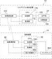
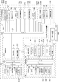
一例として図3に示すように、管理装置14は、主制御部80、無線通信部82、受付デバイス84、タッチパネル・ディスプレイ86、及び外部I/F88を備えている。
As an example, as shown in FIG. 3, the management device 14 includes a main control unit 80, a wireless communication unit 82, a reception device 84, a touch panel display 86, and an external I / F 88.
主制御部80は、CPU90、一次記憶部92、二次記憶部94、バスライン96、及びI/O98を含む。CPU90、一次記憶部92、及び二次記憶部94は、バスライン96を介して接続されている。バスライン96には、I/O98が接続されている。なお、本実施形態では、CPU90として単数のCPUを採用しているが、CPU90に代えて複数のCPUを採用してもよい。
The main control unit 80 includes a CPU 90, a primary storage unit 92, a secondary storage unit 94, a bus line 96, and an I / O 98. The CPU 90, the primary storage unit 92, and the secondary storage unit 94 are connected via the bus line 96. I / O 98 is connected to the bus line 96. In this embodiment, a single CPU is used as the CPU 90, but a plurality of CPUs may be used instead of the CPU 90.
CPU90は、管理装置14の全体を制御する。一次記憶部92は、各種プログラムの実行時のワークエリア等として用いられる揮発性のメモリであり、一次記憶部92の一例としては、RAMが挙げられる。二次記憶部94は、管理装置14の基本的な動作を制御するプログラム及び各種パラメータ等を記憶する不揮発性のメモリである。二次記憶部94の一例としては、HDD、EEPROM、又はフラッシュメモリ等が挙げられる。
The CPU 90 controls the entire management device 14. The primary storage unit 92 is a volatile memory used as a work area or the like when executing various programs, and an example of the primary storage unit 92 is a RAM. The secondary storage unit 94 is a non-volatile memory that stores a program that controls the basic operation of the management device 14, various parameters, and the like. An example of the secondary storage unit 94 is an HDD, EEPROM, a flash memory, or the like.
無線通信部82は、I/O98に接続されている。CPU90は、制御装置18への送信対象とされる電気信号を無線通信部82に出力する。無線通信部82は、CPU90から入力された電気信号を電波で制御装置18に送信する。また、無線通信部82は、制御装置18からの電波を受信し、受信した電波に応じた電気信号をCPU90に出力する。
The wireless communication unit 82 is connected to the I / O 98. The CPU 90 outputs an electric signal to be transmitted to the control device 18 to the wireless communication unit 82. The wireless communication unit 82 transmits the electric signal input from the CPU 90 to the control device 18 by radio waves. Further, the wireless communication unit 82 receives the radio wave from the control device 18 and outputs an electric signal corresponding to the received radio wave to the CPU 90.
なお、無線通信部112は、本開示の技術に係る通信部の一例である。すなわち、無線通信部82は、ウエアラブル端末装置12に対して、ウエアラブル端末装置12を制御する制御情報であって、患者の両眼のうちの眼科検査の検査対象眼を指示する指示情報を有する制御情報をウエアラブル端末装置12に対して送信する。
The wireless communication unit 112 is an example of the communication unit according to the technique of the present disclosure. That is, the wireless communication unit 82 controls the wearable terminal device 12 with control information for controlling the wearable terminal device 12 and having instruction information for instructing the eye to be examined in the ophthalmic examination among both eyes of the patient. Information is transmitted to the wearable terminal device 12.
受付デバイス84は、タッチパネル84A、キーボード84B、及びマウス84Cを含み、タッチパネル84A、キーボード84B、及びマウス84Cは、I/O98に接続されている。従って、CPU90は、タッチパネル84A、キーボード84B、及びマウス84Cの各々によって受け付けられた各種指示を把握することができる。
The reception device 84 includes a touch panel 84A, a keyboard 84B, and a mouse 84C, and the touch panel 84A, the keyboard 84B, and the mouse 84C are connected to the I / O 98. Therefore, the CPU 90 can grasp various instructions received by each of the touch panel 84A, the keyboard 84B, and the mouse 84C.
外部I/F88は、サーバ装置15、パーソナル・コンピュータ、及び/又はUSBメモリ等の外部装置に接続され、外部装置とCPU90との間の各種情報の送受信を司る。なお、図3に示す例では、外部I/F88は、ケーブル23を介してサーバ装置15に接続されている。
The external I / F 88 is connected to an external device such as a server device 15, a personal computer, and / or a USB memory, and controls transmission / reception of various information between the external device and the CPU 90. In the example shown in FIG. 3, the external I / F 88 is connected to the server device 15 via the cable 23.
タッチパネル・ディスプレイ86は、ディスプレイ86A及びタッチパネル84Aを含む。ディスプレイ86Aは、本開示の技術に係る表示部の一例である。ディスプレイ86Aは、I/O98に接続されており、CPU90の制御下で、映像を含む各種情報を表示する。タッチパネル84Aは、透過型のタッチパネルであり、ディスプレイ86Aに重ねられている。
The touch panel display 86 includes a display 86A and a touch panel 84A. The display 86A is an example of a display unit according to the technique of the present disclosure. The display 86A is connected to the I / O 98 and displays various information including video under the control of the CPU 90. The touch panel 84A is a transmissive touch panel and is superimposed on the display 86A.
二次記憶部94は、端末管理プログラム94A、表示制御プログラム94B、及び通信エラー対応プログラム94Cを記憶している。以下では、説明の便宜上、端末管理プログラム94A、表示制御プログラム94B、及び通信エラー対応プログラム94Cを区別して説明する必要がない場合、これらを「管理装置側プログラム」と称する。
The secondary storage unit 94 stores the terminal management program 94A, the display control program 94B, and the communication error response program 94C. In the following, for convenience of explanation, when it is not necessary to separately explain the terminal management program 94A, the display control program 94B, and the communication error response program 94C, these are referred to as "management device side programs".
CPU90は、二次記憶部94から管理装置側プログラムを読み出し、読み出した管理装置側プログラムを一次記憶部92に展開する。そして、CPU90は、一次記憶部92に展開した管理装置側プログラムを実行する。
The CPU 90 reads a program on the management device side from the secondary storage unit 94, and expands the read program on the management device side to the primary storage unit 92. Then, the CPU 90 executes the management device side program expanded in the primary storage unit 92.
制御装置18は、前述した応答ボタン19の他に、主制御部110、無線通信部112、レーザ光源114、及び光源制御回路116を備えている。
In addition to the response button 19 described above, the control device 18 includes a main control unit 110, a wireless communication unit 112, a laser light source 114, and a light source control circuit 116.
主制御部110は、CPU120、一次記憶部122、二次記憶部124、バスライン126、及びI/O128を含む。CPU120、一次記憶部122、及び二次記憶部124は、バスライン126を介して接続されている。バスライン126には、I/O128が接続されている。なお、本実施形態では、CPU120として単数のCPUを採用しているが、CPU120に代えて複数のCPUを採用してもよい。
The main control unit 110 includes a CPU 120, a primary storage unit 122, a secondary storage unit 124, a bus line 126, and an I / O 128. The CPU 120, the primary storage unit 122, and the secondary storage unit 124 are connected via the bus line 126. I / O 128 is connected to the bus line 126. In this embodiment, a single CPU is used as the CPU 120, but a plurality of CPUs may be used instead of the CPU 120.
CPU120は、ウエアラブル端末装置12の全体を制御する。一次記憶部122は、各種プログラムの実行時のワークエリア等として用いられる揮発性のメモリであり、一次記憶部122の一例としては、RAMが挙げられる。二次記憶部124は、ウエアラブル端末装置12の基本的な動作を制御するプログラム及び各種パラメータ等を記憶する不揮発性のメモリである。二次記憶部124の一例としては、HDD、EEPROM、又はフラッシュメモリ等が挙げられる。
The CPU 120 controls the entire wearable terminal device 12. The primary storage unit 122 is a volatile memory used as a work area or the like when executing various programs, and an example of the primary storage unit 122 is a RAM. The secondary storage unit 124 is a non-volatile memory that stores a program that controls the basic operation of the wearable terminal device 12, various parameters, and the like. An example of the secondary storage unit 124 is an HDD, EEPROM, a flash memory, or the like.
応答ボタン19は、I/O128に接続されており、応答ボタン19が押下されると、応答信号が応答ボタン19からCPU120に出力される。
The response button 19 is connected to the I / O 128, and when the response button 19 is pressed, a response signal is output from the response button 19 to the CPU 120.
無線通信部112は、ウエアラブル端末装置12による視野検査の管理を管理装置14に対して行わせるように管理装置14との間で無線通信を行う。無線通信部112は、I/O128に接続されている。CPU120は、管理装置14への送信対象とされる電気信号を無線通信部112に出力する。無線通信部112は、CPU120から入力された電気信号を電波で管理装置14に送信する。また、無線通信部112は、管理装置14からの電波を受信し、受信した電波に応じた電気信号をCPU120に出力する。
The wireless communication unit 112 performs wireless communication with the management device 14 so that the management device 14 manages the visual field inspection by the wearable terminal device 12. The wireless communication unit 112 is connected to the I / O 128. The CPU 120 outputs an electric signal to be transmitted to the management device 14 to the wireless communication unit 112. The wireless communication unit 112 transmits the electric signal input from the CPU 120 to the management device 14 by radio waves. Further, the wireless communication unit 112 receives the radio wave from the management device 14, and outputs an electric signal corresponding to the received radio wave to the CPU 120.
レーザ光源114は、光ファイバ30を介して光分岐部20に接続されている。レーザ光源114は、レーザ光を生成し、生成したレーザ光を、光ファイバ30を介して光分岐部20に射出する。
The laser light source 114 is connected to the optical branch portion 20 via an optical fiber 30. The laser light source 114 generates laser light, and emits the generated laser light to the optical branch portion 20 via the optical fiber 30.
レーザ光源114は、光源制御回路116に接続されている。光源制御回路116は、I/O128に接続されている。光源制御回路116は、CPU120の指示に従って光源制御信号をレーザ光源に供給することで、レーザ光源114を制御する。
The laser light source 114 is connected to the light source control circuit 116. The light source control circuit 116 is connected to the I / O 128. The light source control circuit 116 controls the laser light source 114 by supplying a light source control signal to the laser light source according to the instruction of the CPU 120.
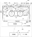
一例として図5に示すように、レーザ光源114は、R光源114A、G光源114B、B光源114C、及びミラーユニット130を備えている。
As an example, as shown in FIG. 5, the laser light source 114 includes an R light source 114A, a G light source 114B, a B light source 114C, and a mirror unit 130.
R光源114Aは、R(赤色)、G(緑色)、及びB(青色)のうちのRのレーザ光であるRレーザ光を射出する。G光源114Bは、R、G、及びBのうちのGのレーザ光であるGレーザ光を射出する。B光源114Cは、R、G、及びBのうちのBのレーザ光であるBレーザ光を射出する。なお、ここでは、レーザ光源114がR光源114A、G光源114B、及びB光源114Cを備えている場合を例示しているが、本開示の技術はこれに限定されるものではない。例えば、レーザ光源114は、IR光源(図示省略)を備えていてもよい。ここで、「IR」とは、“near-infrared”の略称を意味する。IR光源は、SLO及び/又はOCTによる撮影用のレーザ光である近赤外光を射出する。
The R light source 114A emits an R laser beam which is an R laser beam among R (red), G (green), and B (blue). The G light source 114B emits a G laser beam, which is a laser beam of G among R, G, and B. The B light source 114C emits a B laser beam, which is a laser beam of B among R, G, and B. Although the case where the laser light source 114 includes the R light source 114A, the G light source 114B, and the B light source 114C is illustrated here, the technique of the present disclosure is not limited to this. For example, the laser light source 114 may include an IR light source (not shown). Here, "IR" means an abbreviation for "near-infrared". The IR light source emits near-infrared light, which is a laser beam for photographing by SLO and / or OCT.
ミラーユニット130は、第1ミラー130A、第2ミラー130B、及び第3ミラー130Cを備えている。第1ミラー130A、第2ミラー130B、及び第3ミラー130Cのうち、第2ミラー130Bは、ダイクロイックミラーであり、Bレーザ光を透過させ、且つ、Gレーザ光を反射する。第3ミラー130Cは、ダイクロイックミラーであり、Rレーザ光を透過させ、且つ、Gレーザ光及びBレーザ光を反射する。
The mirror unit 130 includes a first mirror 130A, a second mirror 130B, and a third mirror 130C. Of the first mirror 130A, the second mirror 130B, and the third mirror 130C, the second mirror 130B is a dichroic mirror, which transmits the B laser light and reflects the G laser light. The third mirror 130C is a dichroic mirror, which transmits R laser light and reflects G laser light and B laser light.
第1ミラー130Aは、B光源114CによるBレーザ光の射出方向に配置されており、B光源114Cから射出されたBレーザ光を反射させることで、第2ミラー130BにBレーザ光を導く。
The first mirror 130A is arranged in the emission direction of the B laser beam by the B light source 114C, and guides the B laser beam to the second mirror 130B by reflecting the B laser beam emitted from the B light source 114C.
第2ミラー130Bは、G光源114BによるGレーザ光の射出方向であり、且つ、第1ミラー130Aで反射されたBレーザ光の進行方向に配置されている。第2ミラー130Bは、G光源114Bから射出されたGレーザ光を反射させることで、第1ミラー130AにGレーザ光を導き、且つ、第1ミラー130Aで反射されたBレーザ光を透過させることで、第1ミラー130AにBレーザ光を導く。
The second mirror 130B is arranged in the emission direction of the G laser beam by the G light source 114B and in the traveling direction of the B laser beam reflected by the first mirror 130A. The second mirror 130B guides the G laser beam to the first mirror 130A by reflecting the G laser beam emitted from the G light source 114B, and transmits the B laser beam reflected by the first mirror 130A. Then, the B laser beam is guided to the first mirror 130A.
第3ミラー130Cは、R光源114AによるRレーザ光の射出方向であり、且つ、第2ミラー130Bで反射されたGレーザ光の進行方向であり、且つ、第2ミラー130Bを透過したGレーザ光の進行方向に配置されている。第3ミラー130Cは、R光源114Aから射出されたRレーザ光を透過させる。また、第3ミラー130Cは、Rレーザ光と同方向にGレーザ光及びBレーザ光を反射させることで、Rレーザ光、Gレーザ光及びBレーザ光を外部に射出する。なお、本実施形態では、説明の便宜上、レーザ光源114から外部に射出されるRレーザ光、Gレーザ光、及びBレーザ光を、単に「レーザ光」と称する。
The third mirror 130C is the emission direction of the R laser beam by the R light source 114A, the traveling direction of the G laser beam reflected by the second mirror 130B, and the G laser beam transmitted through the second mirror 130B. It is arranged in the direction of travel of. The third mirror 130C transmits the R laser beam emitted from the R light source 114A. Further, the third mirror 130C emits the R laser beam, the G laser beam and the B laser beam to the outside by reflecting the G laser beam and the B laser beam in the same direction as the R laser beam. In the present embodiment, for convenience of explanation, the R laser light, the G laser light, and the B laser light emitted from the laser light source 114 to the outside are simply referred to as "laser light".
一例として図3に示すように、バスライン32は、I/O128に接続されており、光分岐部20は、バスライン32に接続されている。従って、光分岐部20は、CPU120の制御下で動作する。
As an example, as shown in FIG. 3, the bus line 32 is connected to the I / O 128, and the optical branch portion 20 is connected to the bus line 32. Therefore, the optical branching unit 20 operates under the control of the CPU 120.
一例として図6に示すように、光分岐部20は、右眼用シャッタ121R、左眼用シャッタ121L、第1スライド機構122R、第2スライド機構122L、第1シャッタ用駆動源134R、第2シャッタ用駆動源134L、ビームスプリッタ136、及び反射ミラー138を備えている。
As an example, as shown in FIG. 6, the optical branching portion 20 includes a right eye shutter 121R, a left eye shutter 121L, a first slide mechanism 122R, a second slide mechanism 122L, a first shutter drive source 134R, and a second shutter. It is equipped with a drive source 134L, a beam splitter 136, and a reflection mirror 138.
なお、以下では、説明の便宜上、右眼用シャッタ121R及び左眼用シャッタ121Lを区別して説明する必要がない場合、「シャッタ121」と称する。
In the following, for convenience of explanation, when it is not necessary to distinguish between the right eye shutter 121R and the left eye shutter 121L, the term “shutter 121” is used.
ビームスプリッタ136は、レーザ光源114から光ファイバ130を介して供給されたレーザ光を反射させ、且つ、透過させる。ビームスプリッタ136で反射したレーザ光である左眼用レーザ光は、光ファイバ40(図1及び図2参照)の入口に向けて進行する。
The beam splitter 136 reflects and transmits the laser light supplied from the laser light source 114 via the optical fiber 130. The laser beam for the left eye, which is the laser beam reflected by the beam splitter 136, travels toward the inlet of the optical fiber 40 (see FIGS. 1 and 2).
反射ミラー138は、ビームスプリッタ136を透過したレーザ光を反射する。反射ミラー138で反射したレーザ光である右眼用レーザ光は、光ファイバ38(図1及び図2参照)の入口に向けて進行する。
The reflection mirror 138 reflects the laser light transmitted through the beam splitter 136. The laser beam for the right eye, which is the laser beam reflected by the reflection mirror 138, travels toward the inlet of the optical fiber 38 (see FIGS. 1 and 2).
第1スライド機構122Rは、右眼用シャッタ121Rを第1位置P1と第2位置P2との間でスライド可能に保持している。第1位置P1とは、右眼用レーザ光を通過させて光ファイバ38の入口に導く位置を指し、第2位置P2とは、右眼用レーザ光を遮蔽する位置を指す。
The first slide mechanism 122R holds the shutter 121R for the right eye slidably between the first position P1 and the second position P2. The first position P1 refers to a position where the laser beam for the right eye is passed and guided to the inlet of the optical fiber 38, and the second position P2 refers to a position where the laser beam for the right eye is shielded.
第2スライド機構122Lは、左眼用シャッタ121Lを第3位置P3と第4位置P4との間でスライド可能に保持している。第3位置P3とは、左眼用レーザ光を通過させて光ファイバ40の入口に導く位置を指し、第4位置P4とは、左眼用レーザ光を遮蔽する位置を指す。
The second slide mechanism 122L holds the left eye shutter 121L slidably between the third position P3 and the fourth position P4. The third position P3 refers to a position where the laser beam for the left eye is passed and guided to the inlet of the optical fiber 40, and the fourth position P4 refers to a position where the laser beam for the left eye is shielded.
第1シャッタ用駆動源134R及び第2シャッタ用駆動源134Lの一例としては、ステッピングモータ、ソレノイド、又は圧電素子などが挙げられる。第1シャッタ用駆動源134R及び第2シャッタ用駆動源134Lは、バスライン32に接続されており、第1シャッタ用駆動源134R及び第2シャッタ用駆動源134Lは、CPU120の制御下で作動する。
Examples of the drive source 134R for the first shutter and the drive source 134L for the second shutter include a stepping motor, a solenoid, a piezoelectric element, and the like. The drive source 134R for the first shutter and the drive source 134L for the second shutter are connected to the bus line 32, and the drive source 134R for the first shutter and the drive source 134L for the second shutter operate under the control of the CPU 120. ..
第1スライド機構122Rは、第1シャッタ用駆動源134Rに接続されており、第1シャッタ用駆動源134Rによって生成された動力を受けることで右眼用シャッタ121Rを第1位置P1と第2位置P2との間でスライドさせる。
The first slide mechanism 122R is connected to the drive source 134R for the first shutter, and receives the power generated by the drive source 134R for the first shutter to move the shutter 121R for the right eye to the first position P1 and the second position. Slide between P2.
第2スライド機構122Lは、第2シャッタ用駆動源134Lに接続されており、第2シャッタ用駆動源134Lによって生成された動力を受けることで左眼用シャッタ121Lを第3位置P3と第4位置P4との間でスライドさせる。
The second slide mechanism 122L is connected to the second shutter drive source 134L, and receives the power generated by the second shutter drive source 134L to move the left eye shutter 121L to the third position P3 and the fourth position. Slide to and from P4.
なお、図6に示す例では、右眼用シャッタ121Rが第1位置P1に配置されているので、右眼用レーザ光は光ファイバ38に供給され、左眼用シャッタ121Lが第4位置P4に配置されているので、左眼用レーザ光は左眼用シャッタ121Lによって遮蔽される。
In the example shown in FIG. 6, since the right eye shutter 121R is arranged at the first position P1, the laser light for the right eye is supplied to the optical fiber 38, and the left eye shutter 121L is located at the fourth position P4. Since it is arranged, the laser beam for the left eye is shielded by the shutter 121L for the left eye.
一例として図3に示すように、スピーカ140は、バスライン32に接続されており、CPU120の制御下で音声を出力する。
As an example, as shown in FIG. 3, the speaker 140 is connected to the bus line 32 and outputs sound under the control of the CPU 120.
バスライン32には、右眼用駆動源72R及び左眼用駆動源72Lが接続されており、CPU120は、右眼用駆動源72R及び左眼用駆動源72Lを制御する。
A drive source 72R for the right eye and a drive source 72L for the left eye are connected to the bus line 32, and the CPU 120 controls the drive source 72R for the right eye and the drive source 72L for the left eye.
バスライン32には、右眼用インカメラ48R及び左眼用インカメラ48Lが接続されており、CPU120は、左眼用インカメラ48L及び右眼用インカメラ48Rとの間で各種情報の授受を行う。
A right-eye in-camera 48R and a left-eye in-camera 48L are connected to the bus line 32, and the CPU 120 exchanges various information between the left-eye in-camera 48L and the right-eye in-camera 48R. conduct.
バスライン32には、右眼用照射部52、左眼用照射部58、及びMEMSミラー54,56,60,62が接続されており、CPU120は、右眼用照射部52、左眼用照射部58、及びMEMSミラー54,56,60,62を制御する。
The irradiation unit 52 for the right eye, the irradiation unit 58 for the left eye, and the MEMS mirrors 54, 56, 60, 62 are connected to the bus line 32, and the CPU 120 has the irradiation unit 52 for the right eye and the irradiation for the left eye. The unit 58 and the MEMS mirrors 54, 56, 60, 62 are controlled.
バスライン32には、装着検出器139が接続されている。装着検出器139は、例えば、感圧センサである。装着検出器139は、アイウエア端末装置16のフレームに設けられており、アイウエア端末装置16が正しく装着されたことを検出する。CPU120は、装着検出器139での検出結果を取得する。なお、アイウエア端末装置350のフレームとは、例えば、リム22及びテンプル24を指す。
A mounting detector 139 is connected to the bus line 32. The mounting detector 139 is, for example, a pressure sensitive sensor. The wearing detector 139 is provided on the frame of the eyewear terminal device 16 and detects that the eyewear terminal device 16 is correctly mounted. The CPU 120 acquires the detection result of the mounting detector 139. The frame of the eyewear terminal device 350 refers to, for example, the rim 22 and the temple 24.
二次記憶部124は、端末側プログラム124Aを記憶している。CPU120は、二次記憶部124から端末側プログラム124Aを読み出し、読み出した端末側プログラム124Aを一次記憶部122に展開する。そして、CPU120は、一次記憶部122に展開した端末側プログラム124Aを実行する。
The secondary storage unit 124 stores the terminal-side program 124A. The CPU 120 reads the terminal-side program 124A from the secondary storage unit 124, and expands the read terminal-side program 124A into the primary storage unit 122. Then, the CPU 120 executes the terminal-side program 124A expanded in the primary storage unit 122.
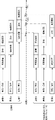
一例として図4に示すように、サーバ装置15は、主制御部150、受付デバイス154、タッチパネル・ディスプレイ156、及び外部I/F158を備えている。
As an example, as shown in FIG. 4, the server device 15 includes a main control unit 150, a reception device 154, a touch panel display 156, and an external I / F 158.
主制御部150は、CPU160、一次記憶部162、二次記憶部164、バスライン166、及びI/O168を含む。CPU160、一次記憶部162、及び二次記憶部164は、バスライン166を介して接続されている。バスライン166には、I/O168が接続されている。なお、本実施形態では、CPU160として単数のCPUを採用しているが、CPU160に代えて複数のCPUを採用してもよい。
The main control unit 150 includes a CPU 160, a primary storage unit 162, a secondary storage unit 164, a bus line 166, and an I / O 168. The CPU 160, the primary storage unit 162, and the secondary storage unit 164 are connected via a bus line 166. An I / O 168 is connected to the bus line 166. In this embodiment, a single CPU is used as the CPU 160, but a plurality of CPUs may be used instead of the CPU 160.
CPU160は、サーバ装置15の全体を制御する。一次記憶部162は、各種プログラムの実行時のワークエリア等として用いられる揮発性のメモリであり、一次記憶部162の一例としては、RAMが挙げられる。二次記憶部164は、サーバ装置164の基本的な動作を制御するプログラム及び各種パラメータ等を記憶する不揮発性のメモリである。二次記憶部164の一例としては、HDD、EEPROM、又はフラッシュメモリ等が挙げられる。
The CPU 160 controls the entire server device 15. The primary storage unit 162 is a volatile memory used as a work area or the like when executing various programs, and an example of the primary storage unit 162 is a RAM. The secondary storage unit 164 is a non-volatile memory that stores a program that controls the basic operation of the server device 164, various parameters, and the like. An example of the secondary storage unit 164 is an HDD, EEPROM, a flash memory, or the like.
受付デバイス154は、タッチパネル154A、キーボード154B、及びマウス154Cを含み、タッチパネル154A、キーボード154B、及びマウス154Cは、I/O168に接続されている。従って、CPU160は、タッチパネル154A、キーボード154B、及びマウス154Cの各々によって受け付けられた各種指示を把握することができる。
The reception device 154 includes a touch panel 154A, a keyboard 154B, and a mouse 154C, and the touch panel 154A, the keyboard 154B, and the mouse 154C are connected to the I / O 168. Therefore, the CPU 160 can grasp various instructions received by each of the touch panel 154A, the keyboard 154B, and the mouse 154C.
外部I/F158は、管理装置14、パーソナル・コンピュータ、及び/又はUSBメモリ等の外部装置に接続され、外部装置とCPU160との間の各種情報の送受信を司る。なお、図3に示す例では、外部I/F158は、ケーブル23を介して管理装置14の外部I/F88に接続されている。
The external I / F 158 is connected to an external device such as a management device 14, a personal computer, and / or a USB memory, and controls transmission / reception of various information between the external device and the CPU 160. In the example shown in FIG. 3, the external I / F 158 is connected to the external I / F 88 of the management device 14 via the cable 23.
タッチパネル・ディスプレイ156は、ディスプレイ156A及びタッチパネル154Aを含む。ディスプレイ86Aは、I/O168に接続されており、CPU160の制御下で、映像を含む各種情報を表示する。タッチパネル154Aは、透過型のタッチパネルであり、ディスプレイ156Aに重ねられている。
The touch panel display 156 includes a display 156A and a touch panel 154A. The display 86A is connected to the I / O 168 and displays various information including video under the control of the CPU 160. The touch panel 154A is a transmissive touch panel and is superimposed on the display 156A.
二次記憶部164は、患者情報164A及びサーバ側プログラム164Bを記憶している。
The secondary storage unit 164 stores the patient information 164A and the server-side program 164B.
患者情報164Aは、患者に関する情報である。本実施形態において、患者情報164Aには、患者のプロフィール情報164A1(例えば、患者を特定するID、患者の名前、患者の性別、患者の年齢、身体情報、過去の治療歴、来院状況など現在の患者情報から、疾患のリスクや身体状態など)と、患者に対して行われた検眼情報164A2(例えば、角膜屈折力、角膜波面収差、視力、近視/遠視/乱視、視野、眼軸長、眼底写真などの別の検眼機器(屈折力測定器、眼軸長測定器、視力検査器、前眼部測定器、後眼部測定器など)により得られた患者の右眼/左眼に関する情報)と、を含む。
Patient information 164A is information about the patient. In the present embodiment, the patient information 164A includes the patient profile information 164A1 (for example, the ID that identifies the patient, the name of the patient, the gender of the patient, the age of the patient, the physical information, the past treatment history, the visit status, etc. From the patient information, the risk of the disease, physical condition, etc.) and the eye examination information 164A2 (for example, corneal refractive force, corneal wave surface aberration, visual acuity, myopic / distant vision / random vision, visual field, axial length, fundus) performed on the patient. Information about the patient's right / left eye obtained by another eye examination device such as a photograph (refractive force measuring device, axial length measuring device, vision tester, anterior eye measuring device, posterior eye measuring device, etc.) And, including.
一例として図4に示すように、ビューワ17は、主制御部17A、タッチパネル・ディスプレイ17B、受付デバイス17D、及び外部I/F17Mを備えている。
As an example, as shown in FIG. 4, the viewer 17 includes a main control unit 17A, a touch panel display 17B, a reception device 17D, and an external I / F 17M.
主制御部17Aは、CPU17H、一次記憶部17I、二次記憶部17J、バスライン17K、及びI/O17Lを含む。CPU17H、一次記憶部17I、及び二次記憶部17Jは、バスライン17Kを介して接続されている。バスライン17Kには、I/O17Lが接続されている。なお、本実施形態では、CPU17Hとして単数のCPUを採用しているが、CPU17Hに代えて複数のCPUを採用してもよい。
The main control unit 17A includes a CPU 17H, a primary storage unit 17I, a secondary storage unit 17J, a bus line 17K, and an I / O 17L. The CPU 17H, the primary storage unit 17I, and the secondary storage unit 17J are connected via the bus line 17K. I / O 17L is connected to the bus line 17K. In this embodiment, a single CPU is used as the CPU 17H, but a plurality of CPUs may be used instead of the CPU 17H.
CPU17Hは、ビューワ17の全体を制御する。一次記憶部17Iは、各種プログラムの実行時のワークエリア等として用いられる揮発性のメモリであり、一次記憶部17Iの一例としては、RAMが挙げられる。二次記憶部17Jは、ビューワ17の基本的な動作を制御するプログラム及び各種パラメータ等を記憶する不揮発性のメモリである。二次記憶部17Jの一例としては、HDD、EEPROM、又はフラッシュメモリ等が挙げられる。二次記憶部164は、ビューワ側プログラム17J1を記憶している。
The CPU 17H controls the entire viewer 17. The primary storage unit 17I is a volatile memory used as a work area or the like when executing various programs, and an example of the primary storage unit 17I is a RAM. The secondary storage unit 17J is a non-volatile memory that stores a program that controls the basic operation of the viewer 17, various parameters, and the like. An example of the secondary storage unit 17J is an HDD, EEPROM, a flash memory, or the like. The secondary storage unit 164 stores the viewer side program 17J1.
受付デバイス17Dは、タッチパネル17E、キーボード17F、及びマウス17Gを含み、タッチパネル17E、キーボード17F、及びマウス17Gは、I/O17Lに接続されている。従って、CPU17Hは、タッチパネル17E、キーボード17F、及びマウス17Gの各々によって受け付けられた各種指示を把握することができる。
The reception device 17D includes a touch panel 17E, a keyboard 17F, and a mouse 17G, and the touch panel 17E, the keyboard 17F, and the mouse 17G are connected to the I / O 17L. Therefore, the CPU 17H can grasp various instructions received by each of the touch panel 17E, the keyboard 17F, and the mouse 17G.
外部I/F17Mは、管理装置14、サーバ装置15、パーソナル・コンピュータ、及び/又はUSBメモリ等の外部装置に接続され、外部装置とCPU17Hとの間の各種情報の送受信を司る。なお、図4に示す例では、外部I/F17Mは、ケーブル23を介して管理装置14の外部I/F88及びサーバ装置15の外部I/F158に接続されている。
The external I / F17M is connected to an external device such as a management device 14, a server device 15, a personal computer, and / or a USB memory, and controls transmission / reception of various information between the external device and the CPU 17H. In the example shown in FIG. 4, the external I / F 17M is connected to the external I / F 88 of the management device 14 and the external I / F 158 of the server device 15 via the cable 23.
タッチパネル・ディスプレイ17Bは、ディスプレイ17C及びタッチパネル17Eを含む。ディスプレイ17Cは、I/O17Lに接続されており、CPU17Hの制御下で、映像を含む各種情報を表示する。タッチパネル17Eは、透過型のタッチパネルであり、ディスプレイ17Cに重ねられている。
The touch panel display 17B includes a display 17C and a touch panel 17E. The display 17C is connected to the I / O 17L and displays various information including an image under the control of the CPU 17H. The touch panel 17E is a transmissive touch panel and is superimposed on the display 17C.
CPU160は、二次記憶部164からサーバ側プログラム164Bを読み出し、読み出したサーバ側プログラム164Bを一次記憶部162に展開する。そして、CPU160は、一次記憶部162に展開したサーバ側プログラム164Bを実行する。
The CPU 160 reads the server-side program 164B from the secondary storage unit 164, and deploys the read server-side program 164B to the primary storage unit 162. Then, the CPU 160 executes the server-side program 164B expanded in the primary storage unit 162.
ウエアラブル端末装置12に含まれる主制御部110のCPU120は、端末側プログラム124Aを実行することで、一例として図14に示すように、制御部170及び処理部172として動作する。
The CPU 120 of the main control unit 110 included in the wearable terminal device 12 operates as the control unit 170 and the processing unit 172 by executing the terminal-side program 124A, as shown in FIG. 14 as an example.
処理部172は、CPU120を制御部170として動作させるために必要な処理を行う。制御部170は、レーザ光が網膜46R及び/又は網膜46Lに照射されることで網膜46R及び/又は網膜46Lの視野検査が行われるように光学系27を制御する。
The processing unit 172 performs processing necessary for operating the CPU 120 as the control unit 170. The control unit 170 controls the optical system 27 so that the visual field test of the retina 46R and / or the retina 46L is performed by irradiating the retina 46R and / or the retina 46L with the laser beam.
また、処理部172は、本開示の技術に係る第1処理部の一例であり、応答ボタン19の操作に応じた処理を行う。応答ボタン19の操作に応じた処理とは、例えば、後述のマーク投影位置情報を一次記憶部122に記憶する処理、及び/又は、応答ボタン19から入力された応答信号に応じて知覚情報を出力する処理を指す。なお、知覚情報とは、患者がレーザ光を視覚的に知覚したことを示す情報を指す。
Further, the processing unit 172 is an example of the first processing unit according to the technique of the present disclosure, and performs processing according to the operation of the response button 19. The processing according to the operation of the response button 19 is, for example, the processing of storing the mark projection position information described later in the primary storage unit 122 and / or outputting the perceptual information according to the response signal input from the response button 19. Refers to the processing to be performed. The perceptual information refers to information indicating that the patient visually perceives the laser beam.
更に、処理部172は、本開示の技術に係る第2処理部の一例であり、視野検査の進捗状況に関する情報を送信する処理を行う。視野検査の進捗状況に関する情報の送信先は、例えば、管理装置14であるが、本開示の技術はこれに限定されるものではない。例えば、視野検査の進捗状況に関する情報が、管理装置14以外のパーソナル・コンピュータ及び/又はサーバ装置などの外部装置に送信されるようにしてもよい。
Further, the processing unit 172 is an example of the second processing unit according to the technique of the present disclosure, and performs a process of transmitting information regarding the progress of the visual field test. The destination of information regarding the progress of the visual field test is, for example, the management device 14, but the technique of the present disclosure is not limited to this. For example, information on the progress of the visual field test may be transmitted to an external device such as a personal computer and / or a server device other than the management device 14.
管理装置14に含まれる主制御部80のCPU90は、端末管理プログラム94Aを実行することで、一例として図14に示すように、処理部180及び取得部182として動作する。また、CPU90は、表示制御プログラム94Bを実行することで、一例として図14に示すように、処理部180及び表示制御部184として動作する。
The CPU 90 of the main control unit 80 included in the management device 14 operates as the processing unit 180 and the acquisition unit 182 by executing the terminal management program 94A, as shown in FIG. 14 as an example. Further, the CPU 90 operates as the processing unit 180 and the display control unit 184 by executing the display control program 94B, as shown in FIG. 14 as an example.
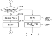
処理部180は、CPU90を取得部182及び表示制御部184として動作させるために必要な処理を行う。取得部182は、視野検査の結果を示す検査結果情報を取得する。検査結果情報の一例としては、後述の視野欠損マップ情報が挙げられる(図9Bのステップ258V参照)。
The processing unit 180 performs processing necessary for operating the CPU 90 as the acquisition unit 182 and the display control unit 184. The acquisition unit 182 acquires inspection result information indicating the result of the visual field inspection. As an example of the test result information, there is a visual field defect map information described later (see step 258V in FIG. 9B).
表示制御部184は、視野検査の進捗状況に応じた画面である進捗状況画面190(図13参照)を生成し、生成した進捗状況画面190を含む画像を示す画像信号を出力する。ディスプレイ86Aは、表示制御部184から入力された画像信号に基づいて進捗状況画面190を表示する。すなわち、表示制御部184は、ディスプレイ86Aに対して、進捗状況画面190を表示させるように、ディスプレイ86Aを制御する。表示制御部184は、無線通信部82,112を介してウエアラブル端末装置12と管理装置14とが通信を行うことで、ウエアラブル端末装置12から視野検査の進捗状況を示す進捗状況情報を取得する。表示制御部184は、進捗状況情報に基づいて進捗状況画面190を生成し、生成した進捗状況画面190をディスプレイ86Aに対して表示させるようにディスプレイ86Aを制御する。
The display control unit 184 generates a progress status screen 190 (see FIG. 13), which is a screen according to the progress status of the visual field test, and outputs an image signal showing an image including the generated progress status screen 190. The display 86A displays the progress screen 190 based on the image signal input from the display control unit 184. That is, the display control unit 184 controls the display 86A so that the display 86A displays the progress status screen 190. The display control unit 184 acquires progress status information indicating the progress status of the visual field test from the wearable terminal device 12 by communicating between the wearable terminal device 12 and the management device 14 via the wireless communication units 82 and 112. The display control unit 184 generates a progress status screen 190 based on the progress status information, and controls the display 86A so that the generated progress status screen 190 is displayed on the display 86A.
なお、本実施形態では、一例として図13に示すように、進捗状況画面190は、第1進捗状況画面190A、第2進捗状況画面190B、第3進捗状況画面190C、第4進捗状況画面190D、第5進捗状況画面190E、及び第6進捗状況画面190Fに大別される。すなわち、ディスプレイ86Aには、第1進捗状況画面190A、第2進捗状況画面190B、第3進捗状況画面190C、第4進捗状況画面190D、第5進捗状況画面190E、及び第6進捗状況画面190Fが表示される。
In the present embodiment, as shown in FIG. 13, as an example, the progress status screen 190 includes the first progress status screen 190A, the second progress status screen 190B, the third progress status screen 190C, and the fourth progress status screen 190D. It is roughly divided into a fifth progress screen 190E and a sixth progress screen 190F. That is, the display 86A has a first progress status screen 190A, a second progress status screen 190B, a third progress status screen 190C, a fourth progress status screen 190D, a fifth progress status screen 190E, and a sixth progress status screen 190F. Is displayed.
次に、眼科システム10の本開示の技術に係る部分の作用について説明する。
Next, the operation of the part of the ophthalmic system 10 according to the technique of the present disclosure will be described.
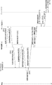
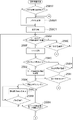
先ず、端末管理処理の実行開始の指示が受付デバイス84によって受け付けられた場合にCPU90が端末管理プログラム94Aを実行することで実現される端末管理処理について図7A及び図7Bを参照して説明する。
First, the terminal management process realized by the CPU 90 executing the terminal management program 94A when the instruction to start the execution of the terminal management process is received by the receiving device 84 will be described with reference to FIGS. 7A and 7B.
また、以下では、説明の便宜上、少なくとも1名の患者がウエアラブル端末装置12を適切に装備していることを前提として説明する。
Further, in the following, for convenience of explanation, it is assumed that at least one patient is appropriately equipped with the wearable terminal device 12.
また、以下では、説明の便宜上、固視標が患者に対して視認可能な状態で提示されていることを前提として説明する。
Further, in the following, for convenience of explanation, it is assumed that the fixative is presented in a state in which it can be visually recognized by the patient.
図7Aに示す端末管理処理では、先ず、ステップ200で、処理部180は、受付デバイス84及び/又はサーバ装置15によって必要な情報が全て受け付けられたか否かを判定する。ここで言う「必要な情報」とは、検査対象眼指示情報、患者ID、及びアイウエアID等の眼科検査に要する情報を指す。検査対象眼指示情報とは、右眼44R及び左眼44Lのうちの検査対象の被検眼44を指示する情報(つまり、右眼44R、左眼44L、及び両眼の何れが検査対象かを示す情報)を指す。患者IDとは、患者を一意に特定可能な情報を指す。アイウエアIDとは、患者に装着されたウエアラブル端末装置12を一意に特定可能な情報を指す。
In the terminal management process shown in FIG. 7A, first, in step 200, the processing unit 180 determines whether or not all the necessary information has been received by the reception device 84 and / or the server device 15. The "necessary information" referred to here refers to information required for an ophthalmologic examination such as an eye instruction information to be examined, a patient ID, and an eyewear ID. The inspection target eye instruction information indicates information indicating which of the right eye 44R and the left eye 44L is the inspection target eye 44 (that is, the right eye 44R, the left eye 44L, and both eyes). Information). The patient ID refers to information that can uniquely identify the patient. The eyewear ID refers to information that can uniquely identify the wearable terminal device 12 worn on the patient.
ステップ200において、受付デバイス84によって必要な情報が全て受け付けられていない場合は、判定が否定されて、ステップ202へ移行する。ステップ200において、受付デバイス84によって必要な情報が全て受け付けられた場合は、判定が肯定されて、ステップ206へ移行する。
If all the necessary information is not received by the reception device 84 in step 200, the determination is denied and the process proceeds to step 202. If all the necessary information is received by the reception device 84 in step 200, the determination is affirmed and the process proceeds to step 206.
ステップ202で、処理部180は、不足情報をディスプレイ86Aに対して表示させ、その後、ステップ204へ移行する。ここで、不足情報とは、例えば、眼科検査に要する情報として不足している情報が何かを示すメッセージを指す。
In step 202, the processing unit 180 displays the shortage information on the display 86A, and then proceeds to step 204. Here, the missing information refers to, for example, a message indicating what kind of information is missing as information required for an ophthalmologic examination.
ステップ204で、処理部180は、端末管理処理に係る終了条件を満足したか否かを判定する。端末管理処理に係る終了条件とは、端末管理処理を終了する条件を指す。端末管理処理に係る終了条件の一例としては、所定時間が経過したとの条件、受付デバイス84が終了指示を受け付けたとの条件、及び/又は端末管理処理を強制的に終了せざるを得ない不具合がCPU90によって検出されたとの条件等が挙げられる。
In step 204, the processing unit 180 determines whether or not the end condition related to the terminal management process is satisfied. The end condition related to the terminal management process refers to a condition for terminating the terminal management process. As an example of the end condition related to the terminal management process, the condition that the predetermined time has elapsed, the condition that the receiving device 84 has received the end instruction, and / or the defect that the terminal management process must be forcibly terminated. The condition that is detected by the CPU 90 and the like can be mentioned.
ステップ204において、端末管理処理に係る終了条件を満足していない場合は、判定が否定されて、ステップ200へ移行する。ステップ204において、端末管理処理に係る終了条件を満足した場合は、判定が肯定されて、端末管理処理を終了する。
If the end condition related to the terminal management process is not satisfied in step 204, the determination is denied and the process proceeds to step 200. If the end condition related to the terminal management process is satisfied in step 204, the determination is affirmed and the terminal management process is terminated.
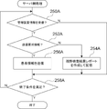
ステップ206で、処理部180は、患者情報164Aの送信を要求する送信要求情報をサーバ装置15に送信し、その後、ステップ208へ移行する。
In step 206, the processing unit 180 transmits the transmission request information requesting the transmission of the patient information 164A to the server device 15, and then proceeds to step 208.
本ステップ206の処理が実行されることで、後述のサーバ側処理に含まれるステップ256の処理によりサーバ装置15から患者情報等が送信される。ここで、患者情報等とは、少なくとも患者情報164Aを含む情報を指す。
By executing the process of this step 206, patient information and the like are transmitted from the server device 15 by the process of step 256 included in the server-side process described later. Here, the patient information and the like refer to information including at least patient information 164A.
ステップ208で、処理部180は、無線通信部82によって患者情報等が受信されたか否かを判定する。ステップ208において、患者情報等が受信されていない場合は、判定が否定されて、ステップ210へ移行する。ステップ206において、患者情報等が受信された場合は、判定が肯定されて、ステップ212へ移行する。
In step 208, the processing unit 180 determines whether or not the patient information or the like has been received by the wireless communication unit 82. If the patient information or the like has not been received in step 208, the determination is denied and the process proceeds to step 210. If the patient information or the like is received in step 206, the determination is affirmed and the process proceeds to step 212.
ステップ210で、処理部180は、端末管理処理に係る終了条件を満足したか否かを判定する。ステップ210において、端末管理処理に係る終了条件を満足していない場合は、判定が否定されて、ステップ208へ移行する。ステップ210において、端末管理処理に係る終了条件を満足した場合は、判定が肯定されて、端末管理処理を終了する。
In step 210, the processing unit 180 determines whether or not the end condition related to the terminal management process is satisfied. If the end condition related to the terminal management process is not satisfied in step 210, the determination is denied and the process proceeds to step 208. If the end condition related to the terminal management process is satisfied in step 210, the determination is affirmed and the terminal management process is terminated.
ステップ212で、処理部180は、無線通信部82,112を介して制御装置18と通信を行うことで、アイウエア端末装置16が患者に正しく装着されているか否かを判定する。ステップ212において、アイウエア端末装置16が患者に正しく装着されていない場合は、判定が否定されて、ステップ214へ移行する。ステップ212において、アイウエア端末装置16が患者に正しく装着されている場合は、判定が肯定されて、ステップ216へ移行する。なお、アイウエア端末装置16が患者に正しく装着されているか否かは、装着検出器139による検出結果に基づいて判定される。
In step 212, the processing unit 180 communicates with the control device 18 via the wireless communication units 82 and 112 to determine whether or not the eyewear terminal device 16 is correctly attached to the patient. If the eyewear terminal device 16 is not correctly attached to the patient in step 212, the determination is denied and the process proceeds to step 214. In step 212, if the eyewear terminal device 16 is correctly attached to the patient, the determination is affirmed and the process proceeds to step 216. Whether or not the eyewear terminal device 16 is correctly worn by the patient is determined based on the detection result of the wearing detector 139.
ステップ214で、処理部180は、端末管理処理に係る終了条件を満足したか否かを判定する。ステップ214において、端末管理処理に係る終了条件を満足していない場合は、判定が否定されて、ステップ212へ移行する。ステップ214において、端末管理処理に係る終了条件を満足した場合は、判定が肯定されて、端末管理処理を終了する。
In step 214, the processing unit 180 determines whether or not the end condition related to the terminal management process is satisfied. If the end condition related to the terminal management process is not satisfied in step 214, the determination is denied and the process proceeds to step 212. If the end condition related to the terminal management process is satisfied in step 214, the determination is affirmed and the terminal management process is terminated.
ステップ216で、処理部180は、制御装置18と無線通信を行うことで、右眼用インカメラ48R及び左眼用インカメラ48Lに対して、被検眼44の前眼部の撮影を開始させ、その後、ステップ217へ移行する。
In step 216, the processing unit 180 wirelessly communicates with the control device 18 to cause the right-eye in-camera 48R and the left-eye in-camera 48L to start photographing the anterior eye portion of the eye to be inspected 44. After that, the process proceeds to step 217.
以下では、説明の便宜上、右眼用インカメラ48Rによって右眼44Rの前眼部が撮影されて得られた画像を右眼前眼部画像と称し、左眼用インカメラ48Lによって左眼44Lの前眼部が撮影されて得られた画像を左眼前眼部画像と称する。また、以下では、説明の便宜上、右眼前眼部画像及び左眼前眼部画像を区別して説明する必要がない場合、単に「前眼部画像」と称する。
In the following, for convenience of explanation, an image obtained by photographing the anterior segment of the right eye 44R by the in-camera 48R for the right eye is referred to as an anterior segment image of the right eye, and is in front of the left eye 44L by the in-camera 48L for the left eye. The image obtained by photographing the eye portion is referred to as a left eye anterior ocular segment image. Further, in the following, for convenience of explanation, when it is not necessary to distinguish between the right eye anterior segment image and the left eye anterior segment image, the term “anterior segment image” is simply referred to.
なお、本実施形態において、左眼用インカメラ48Lによる左眼44Lの前眼部の撮影、及び右眼用インカメラ48Rによる右眼44Rの前眼部の撮影は、60fps(フレーム/秒)のフレームレートで行われる。すなわち、左眼用インカメラ48L及び右眼用インカメラ48Rを作動させることにより、被検眼44の前眼部を被写体とした動画像が処理部180によって取得される。
In the present embodiment, the image of the anterior segment of the left eye 44L by the left-eye in-camera 48L and the imaging of the anterior segment of the right eye 44R by the right-eye in-camera 48R are 60 fps (frames / second). It is done at the frame rate. That is, by operating the left-eye in-camera 48L and the right-eye in-camera 48R, the processing unit 180 acquires a moving image with the anterior eye portion of the eye to be inspected 44 as the subject.
ステップ217で、処理部217は、調整指示情報をウエアラブル端末装置12に送信し、その後、ステップ218へ移行する。ここで、調整指示情報とは、反射ミラー42の位置の調整、レーザ光の光軸の補正、及び原点出しをウエアラブル端末装置12に指示する情報を指す。
In step 217, the processing unit 217 transmits the adjustment instruction information to the wearable terminal device 12, and then proceeds to step 218. Here, the adjustment instruction information refers to information instructing the wearable terminal device 12 to adjust the position of the reflection mirror 42, correct the optical axis of the laser beam, and set the origin.
ステップ218(図7B参照)で、処理部180は、制御装置18と無線通信を行うことで、スピーカ140に対してテスト用の音声を出力させ、スピーカ140の音声が良好か否かを判定する。テスト用の音声とは、例えば、「音が聞こえたら応答ボタンを押して下さい」等の音声を指す。従って、例えば、スピーカ140の音声が良好か否かは、スピーカ140からテスト用の音声が出力されている間に、患者によって応答ボタン19が押されたか否かによって判定される。
In step 218 (see FIG. 7B), the processing unit 180 wirelessly communicates with the control device 18 to output the test voice to the speaker 140, and determines whether the voice of the speaker 140 is good or not. .. The test voice refers to a voice such as "Please press the response button when you hear the sound". Therefore, for example, whether or not the sound of the speaker 140 is good is determined by whether or not the response button 19 is pressed by the patient while the test sound is being output from the speaker 140.
ステップ218において、スピーカ140の音声が良好でない場合は、判定が否定されて、ステップ220へ移行する。ステップ218において、スピーカ140の音声が良好の場合は、判定が肯定されて、ステップ222へ移行する。
If the sound of the speaker 140 is not good in step 218, the determination is denied and the process proceeds to step 220. If the sound of the speaker 140 is good in step 218, the determination is affirmed and the process proceeds to step 222.
ステップ220で、処理部180は、端末管理処理に係る終了条件を満足したか否かを判定する。ステップ220において、端末管理処理に係る終了条件を満足していない場合は、判定が否定されて、ステップ218へ移行する。ステップ220において、端末管理処理に係る終了条件を満足した場合は、判定が肯定されて、端末管理処理を終了する。
In step 220, the processing unit 180 determines whether or not the end condition related to the terminal management process is satisfied. If the end condition related to the terminal management process is not satisfied in step 220, the determination is denied and the process proceeds to step 218. If the end condition related to the terminal management process is satisfied in step 220, the determination is affirmed and the terminal management process is terminated.
ステップ222で、処理部180は、受付デバイス84によって視野検査指示が受け付けられたか否かを判定する。視野検査指示とは、ウエアラブル端末装置12に対して後述の視野検査処理を実行させる指示を指す。
In step 222, the processing unit 180 determines whether or not the visual field inspection instruction has been received by the reception device 84. The visual field inspection instruction refers to an instruction to cause the wearable terminal device 12 to execute the visual field inspection process described later.
ステップ222において、受付デバイス84によって視野検査指示が受け付けられていない場合は、判定が否定されて、ステップ224へ移行する。ステップ222において、受付デバイス84によって視野検査指示が受け付けられた場合は、判定が肯定されて、ステップ226へ移行する。
If the visual field test instruction is not received by the reception device 84 in step 222, the determination is denied and the process proceeds to step 224. If the visual field test instruction is received by the reception device 84 in step 222, the determination is affirmed and the process proceeds to step 226.
ステップ224で、処理部180は、端末管理処理に係る終了条件を満足したか否かを判定する。ステップ224において、端末管理処理に係る終了条件を満足していない場合は、判定が否定されて、ステップ222へ移行する。ステップ224において、端末管理処理に係る終了条件を満足した場合は、判定が肯定されて、端末管理処理を終了する。
In step 224, the processing unit 180 determines whether or not the end condition related to the terminal management process is satisfied. If the end condition related to the terminal management process is not satisfied in step 224, the determination is denied and the process proceeds to step 222. If the end condition related to the terminal management process is satisfied in step 224, the determination is affirmed and the terminal management process is terminated.
ステップ226で、処理部180は、本開示の技術の一例である視野検査指示情報をウエアラブル端末装置12に送信し、その後、ステップ228へ移行する。なお、視野検査指示情報とは、ウエアラブル端末装置12に対して後述の視野検査処理(図9A及び図9B)の実行を指示する情報を指す。また、視野検査指示情報には、ステップ200において受け付けられた必要な情報と、ステップ208において無線通信部82によって受信された患者情報等とが含まれる。
In step 226, the processing unit 180 transmits the visual field inspection instruction information, which is an example of the technique of the present disclosure, to the wearable terminal device 12, and then proceeds to step 228. The visual field inspection instruction information refers to information instructing the wearable terminal device 12 to execute the visual field inspection process (FIGS. 9A and 9B) described later. Further, the visual field test instruction information includes necessary information received in step 200, patient information received by the wireless communication unit 82 in step 208, and the like.
本実施形態では、端末側プログラム124Aに視野検査用の複数のマーク投影位置情報が組み込まれている。マーク投影位置情報とは、網膜46にマークを投影する位置(以下、「マーク投影位置」又は「投影位置」とも言う)を示す情報を指す。ここで言う「マーク」とは、例えば、正常な網膜46であれば白色点として知覚されるマークを指す。網膜46へのマークの投影は、レーザ光の照射により実現される。
In the present embodiment, a plurality of mark projection position information for visual field inspection is incorporated in the terminal side program 124A. The mark projection position information refers to information indicating a position where the mark is projected on the retina 46 (hereinafter, also referred to as “mark projection position” or “projection position”). The "mark" here refers to a mark that is perceived as a white point in the case of a normal retina 46, for example. The projection of the mark on the retina 46 is realized by irradiation with a laser beam.
また、マークの投影位置情報とともにレーザ光の明るさ(強度)を示す情報を組み合わせて、マーク投影情報を視野検査用に保持しておいてもよい。投影位置と明るさ情報とが組み合わされることにより、網膜の感度の情報を視野検査で得ることが可能となる。
Further, the mark projection information may be retained for the visual field inspection by combining the information indicating the brightness (intensity) of the laser beam together with the mark projection position information. By combining the projection position and the brightness information, it becomes possible to obtain information on the sensitivity of the retina by a visual field test.
また、端末側プログラム124A内の複数のマーク投影位置情報は、制御装置18の制御部170によってスキャナ28の制御に用いられる。すなわち、スキャナ28が制御部170によって複数のマーク投影位置情報に従って制御されることで、複数のマーク投影位置情報の各々により示される位置(マーク投影位置情報に従った投影位置)にレーザ光が照射される。
Further, the plurality of mark projection position information in the terminal side program 124A is used for controlling the scanner 28 by the control unit 170 of the control device 18. That is, the scanner 28 is controlled by the control unit 170 according to the plurality of mark projection position information, so that the laser beam irradiates the position indicated by each of the plurality of mark projection position information (projection position according to the mark projection position information). Will be done.
ステップ228で、取得部182は、ウエアラブル端末装置12から送信される視野欠損マップ情報が無線通信部82によって受信されたか否かを判定する。なお、視野欠損マップ情報は、後述の端末側処理に含まれるステップ260の処理が処理部172によって実行されることでウエアラブル端末装置12から送信される。
In step 228, the acquisition unit 182 determines whether or not the visual field defect map information transmitted from the wearable terminal device 12 has been received by the wireless communication unit 82. The visual field defect map information is transmitted from the wearable terminal device 12 by the processing unit 172 executing the processing of step 260 included in the terminal side processing described later.
ステップ228において、ウエアラブル端末装置12から送信される視野欠損マップ情報が無線通信部82によって受信されていない場合は、判定が否定されて、ステップ230へ移行する。ステップ228において、ウエアラブル端末装置12から送信される視野欠損マップ情報が無線通信部82によって受信された場合は、判定が肯定されて、ステップ232へ移行する。
In step 228, if the visual field defect map information transmitted from the wearable terminal device 12 is not received by the wireless communication unit 82, the determination is denied and the process proceeds to step 230. In step 228, when the visual field defect map information transmitted from the wearable terminal device 12 is received by the wireless communication unit 82, the determination is affirmed and the process proceeds to step 232.
ステップ230で、処理部180は、端末管理処理に係る終了条件を満足したか否かを判定する。ステップ230において、端末管理処理に係る終了条件を満足していない場合は、判定が否定されて、ステップ228へ移行する。ステップ230において、端末管理処理に係る終了条件を満足した場合は、判定が肯定されて、端末管理処理を終了する。
In step 230, the processing unit 180 determines whether or not the end condition related to the terminal management process is satisfied. If the end condition related to the terminal management process is not satisfied in step 230, the determination is denied and the process proceeds to step 228. If the end condition related to the terminal management process is satisfied in step 230, the determination is affirmed and the terminal management process is terminated.
ステップ232で、取得部182は、ステップ228において無線通信部82によって受信された視野欠損マップ情報を取得し、その後、ステップ234へ移行する。
In step 232, the acquisition unit 182 acquires the visual field defect map information received by the wireless communication unit 82 in step 228, and then proceeds to step 234.
ステップ234で、処理部180は、制御装置18と無線通信を行うことで、右眼用インカメラ48R及び左眼用インカメラ48Lに対して、被検眼44の前眼部の撮影を終了させ、その後、ステップ236へ移行する。
In step 234, the processing unit 180 wirelessly communicates with the control device 18 to end the imaging of the anterior segment of the eye 44 with respect to the in-camera 48R for the right eye and the in-camera 48L for the left eye. After that, the process proceeds to step 236.
ステップ236で、処理部180は、ステップ232で取得部182によって取得された視野欠損マップ情報をサーバ装置15に送信し、その後、端末管理処理を終了する。なお、管理装置14の処理部180と表示制御部184とによって、ウエアラブル端末装置12から送信される情報に基づいて、適宜、図13に示す進捗状況画面190の表示内容が更新され、表示内容が更新された進捗状況画面190がディスプレイ86Aに表示される。
In step 236, the processing unit 180 transmits the visual field defect map information acquired by the acquisition unit 182 in step 232 to the server device 15, and then ends the terminal management process. The processing unit 180 and the display control unit 184 of the management device 14 appropriately update the display content of the progress status screen 190 shown in FIG. 13 based on the information transmitted from the wearable terminal device 12, and the display content is changed. The updated progress screen 190 is displayed on the display 86A.
次に、ウエアラブル端末装置12の主電源(図示省略)が投入された場合にCPU120が端末側プログラム124Aを実行することで実現される端末側処理について図8を参照して説明する。
Next, the terminal-side processing realized by the CPU 120 executing the terminal-side program 124A when the main power supply (not shown) of the wearable terminal device 12 is turned on will be described with reference to FIG.
図8に示す端末側処理では、ステップ250で、処理部172は、管理装置14からの視野検査指示情報が無線通信部112によって受信されたか否かを判定する。ステップ250において、管理装置14からの視野検査指示情報が無線通信部112によって受信されていない場合は、判定が否定されて、ステップ252へ移行する。ステップ250において、管理装置14からの視野検査指示情報が無線通信部112によって受信された場合は、判定が肯定されて、ステップ258へ移行する。
In the terminal-side processing shown in FIG. 8, in step 250, the processing unit 172 determines whether or not the visual field inspection instruction information from the management device 14 has been received by the wireless communication unit 112. In step 250, if the visual field inspection instruction information from the management device 14 is not received by the wireless communication unit 112, the determination is denied and the process proceeds to step 252. In step 250, when the visual field inspection instruction information from the management device 14 is received by the wireless communication unit 112, the determination is affirmed and the process proceeds to step 258.
ステップ252で、処理部172は、端末管理処理に含まれるステップ217の処理が実行されることによって管理装置14から送信される調整指示情報が無線通信部112によって受信されたか否かを判定する。ステップ252において、調整指示情報が無線通信部112によって受信されていない場合は、判定が否定されて、ステップ256へ移行する。ステップ252において、調整指示情報が無線通信部112によって受信された場合は、判定が肯定されて、ステップ254へ移行する。
In step 252, the processing unit 172 determines whether or not the adjustment instruction information transmitted from the management device 14 is received by the wireless communication unit 112 by executing the process of step 217 included in the terminal management process. If the adjustment instruction information is not received by the wireless communication unit 112 in step 252, the determination is denied and the process proceeds to step 256. If the adjustment instruction information is received by the wireless communication unit 112 in step 252, the determination is affirmed and the process proceeds to step 254.
ステップ254で、制御部170は、反射ミラー42の位置の調整、レーザ光の光軸の補正、及び原点出しを行った後、ステップ256へ移行する。
In step 254, the control unit 170 adjusts the position of the reflection mirror 42, corrects the optical axis of the laser beam, and sets the origin, and then proceeds to step 256.
ステップ254では、反射ミラー42の位置の調整、レーザ光の光軸の補正、及び原点出しを行うために、先ず、最新の右眼前眼部画像と最新の左眼前眼部画像とに基づいて瞳孔間距離が制御部170によって検出される。そして、ウエアラブル端末装置12のアイウエアID及び検出された瞳孔間距離等に基づいて、制御部170によって、反射ミラー42の位置の調整、レーザ光の光軸の補正、及び原点出しが行われる。なお、ここで、瞳孔間距離とは、右眼前眼部画像により示される右眼44Rの前眼部内の瞳孔と左眼前眼部画像により示される左眼44Lの前眼部内の瞳孔との間の距離を指す。また、反射ミラー42の位置は、ミラー駆動源72が制御部170によって制御されることで調整される。また、レーザ光の光軸の補正及び原点出しは、スキャナ28が制御部170によって制御されることで実現される。
In step 254, in order to adjust the position of the reflection mirror 42, correct the optical axis of the laser beam, and determine the origin, first, the pupil is based on the latest right eye anterior segment image and the latest left eye anterior segment image. The interpupillary distance is detected by the control unit 170. Then, based on the eyewear ID of the wearable terminal device 12, the detected interpupillary distance, and the like, the control unit 170 adjusts the position of the reflection mirror 42, corrects the optical axis of the laser beam, and sets the origin. Here, the interpupillary distance refers to the pupil in the anterior segment of the right eye 44R shown by the image of the anterior segment of the right eye and the pupil in the anterior segment of the left eye 44L indicated by the image of the anterior segment of the left eye. Refers to the distance between. Further, the position of the reflection mirror 42 is adjusted by controlling the mirror drive source 72 by the control unit 170. Further, the correction of the optical axis of the laser beam and the origin setting are realized by controlling the scanner 28 by the control unit 170.
ステップ256で、処理部171は、端末側処理に係る終了条件を満足したか否かを判定する。端末側処理に係る終了条件とは、端末側処理を終了する条件を指す。端末側処理に係る終了条件の一例としては、所定時間が経過したとの条件、管理装置14から終了指示を示す情報を受信したとの条件、及び/又は端末側処理を強制的に終了せざるを得ない不具合がCPU120によって検出されたとの条件等が挙げられる。
In step 256, the processing unit 171 determines whether or not the end condition related to the terminal side processing is satisfied. The end condition related to the terminal side processing refers to the condition for terminating the terminal side processing. As an example of the end condition related to the terminal side processing, the condition that the predetermined time has elapsed, the condition that the information indicating the end instruction is received from the management device 14, and / or the terminal side processing must be forcibly terminated. The condition that the trouble that cannot be obtained is detected by the CPU 120 and the like can be mentioned.
ステップ256において、端末側処理に係る終了条件を満足していない場合は、判定が否定されて、ステップ250へ移行する。ステップ256において、端末側処理に係る終了条件を満足した場合は、判定が肯定されて、端末側処理を終了する。
If the end condition related to the terminal side processing is not satisfied in step 256, the determination is denied and the process proceeds to step 250. If the end condition related to the terminal-side processing is satisfied in step 256, the determination is affirmed and the terminal-side processing is terminated.
ステップ258で、制御部170は、一例として図9A及び図9Bに示す視野検査処理を実行し、その後、ステップ260へ移行する。
In step 258, the control unit 170 executes the visual field inspection process shown in FIGS. 9A and 9B as an example, and then proceeds to step 260.
一例として図9Aに示すように、視野検査処理では、ステップ258Aで、制御部170は、視野検査指示情報に含まれる前述の必要な情報内の検査対象眼指示情報に基づいて、シャッタ121を移動させる必要があるか否かを判定する。
As shown in FIG. 9A as an example, in the visual field inspection process, in step 258A, the control unit 170 moves the shutter 121 based on the inspection target eye instruction information in the above-mentioned necessary information included in the visual field inspection instruction information. Determine if it needs to be done.
ステップ258Aにおいて、シャッタ121を移動させる必要がない場合は、判定が否定されて、ステップ258Cへ移行する。ステップ258Aにおいて、シャッタ121を移動させる必要がある場合は、判定が肯定されて、ステップ258Bへ移行する。
If it is not necessary to move the shutter 121 in step 258A, the determination is denied and the process proceeds to step 258C. If it is necessary to move the shutter 121 in step 258A, the determination is affirmed and the process proceeds to step 258B.
ステップ258Bで、制御部170は、視野検査指示情報に含まれる前述の必要な情報内の検査対象眼指示情報に基づいてシャッタ121を移動させ、その後、ステップ258Cへ移行する。
In step 258B, the control unit 170 moves the shutter 121 based on the inspection target eye instruction information in the above-mentioned necessary information included in the visual field inspection instruction information, and then shifts to step 258C.
ステップ258Cで、制御部170は、光管理部114及び光学系27に対して、検査対象眼の網膜46へのレーザ光による走査を開始させ、その後、ステップ258Dへ移行する。
In step 258C, the control unit 170 causes the optical control unit 114 and the optical system 27 to start scanning the retina 46 of the eye to be inspected with a laser beam, and then proceeds to step 258D.
ステップ258Dで、制御部170は、端末側プログラム124A内の複数のマーク投影位置情報のうちの1つのマーク投影位置情報により示される位置にレーザ光が到達したか否かを判定する。なお、本ステップ258Dでは、「1つのマーク投影位置情報」として、ステップ258Mにおいて判定が肯定された場合、再び同じマーク投影位置情報が用いられる。また、本ステップ258Dでは、「1つのマーク投影位置情報」として、ステップ258Nにおいて判定が否定された場合、複数のマーク投影位置情報のうちの未使用のマーク投影位置情報が用いられる。
In step 258D, the control unit 170 determines whether or not the laser beam has reached the position indicated by the mark projection position information of one of the plurality of mark projection position information in the terminal side program 124A. In this step 258D, if the determination is affirmed in step 258M, the same mark projection position information is used again as "one mark projection position information". Further, in this step 258D, when the determination is denied in step 258N, unused mark projection position information among the plurality of mark projection position information is used as "one mark projection position information".
本実施形態では、本ステップ258Dにおいて複数のマーク投影位置情報が用いられる順序は予め定められているが、本開示の技術はこれに限定されるものではない。例えば、管理装置14を介して医療サービス者によって指示されたマーク投影位置情報が本ステップ258Dで用いられるようにしてもよい。また、本ステップ258Dで用いられるマーク投影位置情報の順序が、管理装置14を介して医療サービス者によって変更されるようにしてもよい。
In the present embodiment, the order in which the plurality of mark projection position information is used in the present step 258D is predetermined, but the technique of the present disclosure is not limited to this. For example, the mark projection position information instructed by the medical service provider via the management device 14 may be used in this step 258D. Further, the order of the mark projection position information used in this step 258D may be changed by the medical service provider via the management device 14.
ステップ258Dにおいて、端末側プログラム124A内の複数のマーク投影位置情報のうちの1つのマーク投影位置情報により示される位置にレーザ光が到達していない場合は、判定が否定されて、ステップ258Eへ移行する。ステップ258Dにおいて、複数のマーク投影位置情報のうちの1つのマーク投影位置情報により示される位置にレーザ光が到達した場合は、判定が肯定されて、ステップ258Fへ移行する。
In step 258D, if the laser beam does not reach the position indicated by the mark projection position information of one of the plurality of mark projection position information in the terminal side program 124A, the determination is denied and the process proceeds to step 258E. do. In step 258D, when the laser beam reaches the position indicated by the mark projection position information of one of the plurality of mark projection position information, the determination is affirmed and the process proceeds to step 258F.
ステップ258Eにおいて、制御部170は、端末側処理に係る終了条件を満足したか否かを判定する。ステップ258Eにおいて、端末側処理に係る終了条件を満足していない場合は、判定が否定されて、ステップ258Dへ移行する。ステップ258Eにおいて、端末側処理に係る終了条件を満足した場合は、判定が肯定されて、端末側処理を終了する。
In step 258E, the control unit 170 determines whether or not the end condition related to the terminal side processing is satisfied. If the end condition related to the terminal side processing is not satisfied in step 258E, the determination is denied and the process proceeds to step 258D. In step 258E, if the end condition relating to the terminal side processing is satisfied, the determination is affirmed and the terminal side processing is terminated.
ステップ258Fで、制御部170は、光源制御回路115を介してレーザ光源ユニット113を制御することで、網膜46に対してマークを投影させ、その後、ステップ258Gへ移行する。なお、マークが投影される位置は、ステップ258Dで用いられた最新のマーク投影位置情報により示される位置である。
In step 258F, the control unit 170 controls the laser light source unit 113 via the light source control circuit 115 to project the mark onto the retina 46, and then shifts to step 258G. The position where the mark is projected is the position indicated by the latest mark projection position information used in step 258D.
ステップ258Gで、制御部170は、応答ボタン19が押されたか否かを判定する。なお、応答ボタン19が押されたか否かは、応答ボタン19から応答信号が入力されたか否かによって判定される。
In step 258G, the control unit 170 determines whether or not the response button 19 has been pressed. Whether or not the response button 19 is pressed is determined by whether or not a response signal is input from the response button 19.
ステップ258Gにおいて、応答ボタン19が押されていない場合は、判定が否定されて、ステップ258Hへ移行する。ステップ258Gにおいて、応答ボタン19が押された場合は、判定が肯定されて、ステップ258Jへ移行する。
If the response button 19 is not pressed in step 258G, the determination is denied and the process proceeds to step 258H. If the response button 19 is pressed in step 258G, the determination is affirmed and the process proceeds to step 258J.
ステップ258Jで、制御部170は、最新のマーク投影位置情報を一次記憶部122に記憶し、その後、ステップ258Kへ移行する。ここで、最新のマーク投影位置情報とは、ステップ258Dで用いられた最新のマーク投影位置情報を指し、換言すると、応答ボタン19が押されたタイミングで網膜46に投影されているマークに関するマーク投影位置情報を指す。
In step 258J, the control unit 170 stores the latest mark projection position information in the primary storage unit 122, and then proceeds to step 258K. Here, the latest mark projection position information refers to the latest mark projection position information used in step 258D, in other words, the mark projection related to the mark projected on the retina 46 at the timing when the response button 19 is pressed. Refers to location information.
ステップ258Hで、制御部170は、ステップ258Fの処理が実行されてから予め定められた時間(例えば、2秒)が経過したか否かを判定する。ステップ258Hにおいて、ステップ258Fの処理が実行されてから予め定められた時間が経過していない場合は、判定が否定されて、ステップ258Gへ移行する。ステップ258Hにおいて、ステップ258Fの処理が実行されてから予め定められた時間が経過した場合は、判定が肯定されて、ステップ258Iへ移行する。
In step 258H, the control unit 170 determines whether or not a predetermined time (for example, 2 seconds) has elapsed since the process of step 258F was executed. In step 258H, if a predetermined time has not elapsed since the process of step 258F was executed, the determination is denied and the process proceeds to step 258G. In step 258H, if a predetermined time has elapsed since the process of step 258F was executed, the determination is affirmed and the process proceeds to step 258I.
ステップ258Iで、制御部170は、端末側処理に係る終了条件を満足したか否かを判定する。ステップ258Iにおいて、端末側処理に係る終了条件を満足していない場合は、判定が否定されて、ステップ258Kへ移行する。ステップ258Iにおいて、端末側処理に係る終了条件を満足した場合は、判定が肯定されて、端末側処理を終了する。
In step 258I, the control unit 170 determines whether or not the end condition related to the terminal side processing is satisfied. If the end condition related to the terminal side processing is not satisfied in step 258I, the determination is denied and the process proceeds to step 258K. In step 258I, if the end condition relating to the terminal side processing is satisfied, the determination is affirmed and the terminal side processing is terminated.
ステップ258Kで、制御部170は、患者の視線が固視標からずれているか否かを判定する。患者の視線が固視標からずれているか否かは、最新の前眼部画像に基づいて判定される。
At step 258K, the control unit 170 determines whether the patient's line of sight deviates from the fixative. Whether or not the patient's line of sight deviates from the fixative is determined based on the latest anterior ocular segment image.
ステップ258Kにおいて、患者の視線が固視標からずれている場合は、判定が肯定されて、ステップ258Lへ移行する。ステップ258Kにおいて、患者の視線が固視標からずれていない場合は、判定が否定されて、ステップ258Nへ移行する。
If the patient's line of sight deviates from the fixative in step 258K, the determination is affirmed and the process proceeds to step 258L. If the patient's line of sight does not deviate from the fixative in step 258K, the determination is denied and the process proceeds to step 258N.
ステップ258Lで、制御部170は、スピーカ140に対して、視線誘導音声を出力させ、その後、ステップ258Mへ移行する。
In step 258L, the control unit 170 causes the speaker 140 to output the line-of-sight guidance voice, and then shifts to step 258M.
視線誘導音声とは、視線を固視標の方向へ誘導する音声を指す。視線誘導音声は、視線と固視標との位置関係に応じて生成される。視線の位置は、最新の前眼部画像に基づいて特定される。なお、視線誘導音声の一例としては、「固視標を見て下さい。」という内容の音声、又は、「もう少し右側を向いて下さい。」という内容の音声等が挙げられる。
The line-of-sight guidance voice refers to a voice that guides the line of sight in the direction of the fixative. The line-of-sight guidance voice is generated according to the positional relationship between the line of sight and the fixative. The position of the line of sight is determined based on the latest anterior segment image. As an example of the line-of-sight guidance voice, a voice with the content "Please look at the fixative" or a voice with the content "Please turn a little more to the right" can be mentioned.
ステップ258Mで、制御部170は、患者の視線と固視標とのずれが解消されたか否かを判定する。患者の視線と固視標とのずれが解消されたか否かは、最新の前眼部画像に基づいて判定される。
At step 258M, the control unit 170 determines whether or not the deviation between the patient's line of sight and the fixative has been resolved. Whether or not the deviation between the patient's line of sight and the fixative is resolved is determined based on the latest anterior ocular segment image.
ステップ258Mにおいて、患者の視線と固視標とのずれが解消されていない場合は、判定が否定されて、ステップ258Lへ移行する。ステップ258Mにおいて、患者の視線と固視標とのずれが解消された場合は、判定が肯定されて、ステップ258Dへ移行する。
If the deviation between the patient's line of sight and the fixative is not resolved in step 258M, the determination is denied and the process proceeds to step 258L. If the deviation between the patient's line of sight and the fixative is resolved in step 258M, the determination is affirmed and the process proceeds to step 258D.
ステップ258Nで、制御部170は、全てのマーク投影位置にマークが投影されたか否かを判定する。ステップ258Nにおいて、全てのマーク投影位置にマークが投影されていない場合は、判定が否定されて、ステップ258Dへ移行する。ステップ258Nにおいて、全てのマーク投影位置にマークが投影された場合は、判定が肯定されて、図9Bに示すステップ258Rへ移行する。
In step 258N, the control unit 170 determines whether or not the mark is projected at all the mark projection positions. If the marks are not projected at all the mark projection positions in step 258N, the determination is denied and the process proceeds to step 258D. If the marks are projected at all the mark projection positions in step 258N, the determination is affirmed and the process proceeds to step 258R shown in FIG. 9B.
ステップ258Rで、制御部170は、視野検査が未実施の検査対象眼があるか否かを判定する。視野検査が未実施の検査対象眼があるか否かは、視野検査指示情報に含まれる前述の必要な情報内の検査対象眼指示情報に基づいて判定される。
In step 258R, the control unit 170 determines whether or not there is an eye to be inspected for which the visual field test has not been performed. Whether or not there is an eye to be inspected for which the visual field test has not been performed is determined based on the eye instruction information to be inspected in the above-mentioned necessary information included in the visual field test instruction information.
ステップ258Rにおいて、視野検査が未実施の検査対象眼がある場合は、判定が肯定されて、ステップ258Sへ移行する。ステップ258Rにおいて、視野検査が未実施の検査対象眼がない場合は、判定が否定されて、ステップ258Uへ移行する。
In step 258R, if there is an eye to be inspected for which the visual field test has not been performed, the determination is affirmed and the process proceeds to step 258S. In step 258R, if there is no eye to be inspected for which the visual field test has not been performed, the determination is denied and the process proceeds to step 258U.
ステップ258Sで、制御部170は、スピーカ140に対して、変更通知音声を出力させ、その後、ステップ258Tへ移行する。変更通知音声とは、検査対象眼が変更されることを患者に通知する音声を指す。なお、変更通知音声の一例としては、「右眼の視野検査が終わりましたので、次に左眼の視野検査を行います。」という内容の音声が挙げられる。
In step 258S, the control unit 170 causes the speaker 140 to output the change notification voice, and then shifts to step 258T. The change notification voice refers to a voice that notifies the patient that the eye to be examined is changed. As an example of the change notification voice, there is a voice that says, "Since the visual field test of the right eye has been completed, the visual field test of the left eye will be performed next."
ステップ258Tで、制御部170は、光管理部114及び光学系27を制御することで、光管理部114及び光学系27に対して、検査対象眼の網膜46へのレーザ光による走査を終了させ、その後、ステップ258Bへ移行する。
In step 258T, the control unit 170 controls the optical control unit 114 and the optical system 27 to terminate the scanning of the optical control unit 114 and the optical system 27 by the laser beam on the retina 46 of the eye to be inspected. After that, the process proceeds to step 258B.
ステップ258Uで、制御部170は、光管理部114及び光学系27を制御することで、光管理部114及び光学系27に対して、検査対象眼の網膜46へのレーザ光による走査を終了させ、その後、ステップ258Vへ移行する。
In step 258U, the control unit 170 controls the optical control unit 114 and the optical system 27 to terminate the scanning of the optical control unit 114 and the optical system 27 by the laser beam to the retina 46 of the eye to be inspected. After that, the process proceeds to step 258V.
ステップ258Vで、制御部170は、ステップ258Jの処理が実行されることで一次記憶部122に記憶されたマーク投影位置情報に基づいて視野欠損マップ情報を作成し、その後、視野検査処理を終了する。
In step 258V, the control unit 170 creates the visual field defect map information based on the mark projection position information stored in the primary storage unit 122 by executing the process of step 258J, and then ends the visual field inspection process. ..
なお、視野欠損マップ情報とは、患者ID、視野欠損マップを描くための情報、及び視野欠損マップの画像等を含む情報を指す。視野欠損マップとは、患者の視野の欠損箇所を特定可能なマップを指す。図13に示す第2進捗状況画面190Bの画像表示領域190B3には、視野欠損マップ240が表示されている。視野欠損マップ240では、無彩色の濃淡で欠損箇所と正常箇所とが表現されており、主な欠損箇所は、黒色で表示されている。
The visual field defect map information refers to information including a patient ID, information for drawing a visual field defect map, an image of the visual field defect map, and the like. The visual field defect map refers to a map that can identify the defective part of the patient's visual field. The visual field defect map 240 is displayed in the image display area 190B3 of the second progress screen 190B shown in FIG. In the visual field defect map 240, the defect portion and the normal portion are represented by shades of achromatic color, and the main defect portion is displayed in black.
図8に示すステップ260で、処理部172は、視野検査処理に含まれるステップ258V(図9B参照)の処理が実行されることで作成された視野欠損マップ情報を、無線通信部112を介して管理装置14に送信し、その後、端末側処理を終了する。
In step 260 shown in FIG. 8, the processing unit 172 transfers the visual field defect map information created by executing the process of step 258V (see FIG. 9B) included in the visual field inspection process via the wireless communication unit 112. It is transmitted to the management device 14, and then the terminal side processing is terminated.
次に、サーバ装置15の主電源(図示省略)が投入された場合にCPU160がサーバ側プログラム164Bを実行することで実現されるサーバ側処理について図10を参照して説明する。
Next, the server-side processing realized by the CPU 160 executing the server-side program 164B when the main power supply (not shown) of the server device 15 is turned on will be described with reference to FIG.
図10に示すサーバ側処理では、先ず、ステップ250Aで、CPU160は、管理装置情報を受信したか否かを判定する。管理装置情報とは、端末管理処理が管理装置14のCPU90によって実行されることでサーバ装置15に送信された情報を指す。
In the server-side process shown in FIG. 10, first, in step 250A, the CPU 160 determines whether or not the management device information has been received. The management device information refers to information transmitted to the server device 15 by executing the terminal management process by the CPU 90 of the management device 14.
ステップ250Aにおいて、管理装置情報を受信していない場合は、判定が否定されて、ステップ258Aへ移行する。ステップ250Aにおいて管理装置情報を受信した場合は、判定が肯定されて、ステップ252Aへ移行する。
If the management device information is not received in step 250A, the determination is denied and the process proceeds to step 258A. When the management device information is received in step 250A, the determination is affirmed and the process proceeds to step 252A.
ステップ252Aで、CPU160は、ステップ250Aで受信した管理装置情報が送信要求情報か否かを判定する。ステップ252Aにおいて、ステップ250Aで受信した管理装置情報が送信要求情報でない場合、すなわち、ステップ250Aで受信した管理装置情報が視野欠損マップ情報の場合は、判定が否定されて、ステップ254Aへ移行する。ステップ252Aにおいて、ステップ250Aで受信した管理装置情報が送信要求情報の場合は、判定が肯定されて、ステップ256Aへ移行する。
In step 252A, the CPU 160 determines whether or not the management device information received in step 250A is transmission request information. In step 252A, if the management device information received in step 250A is not transmission request information, that is, if the management device information received in step 250A is visual field defect map information, the determination is denied and the process proceeds to step 254A. In step 252A, if the management device information received in step 250A is transmission request information, the determination is affirmed and the process proceeds to step 256A.
ステップ254Aで、CPU160Aは、視野欠損マップ情報に基づいて、視野検査の結果を示すレポートである視野検査結果レポートを作成し、作成した視野検査結果レポートを二次記憶部164に記憶し、その後、ステップ258Aへ移行する。作成された視野検査結果レポートは、例えば、ビューワ17等の外部機器から要求があった場合にビューワ17に送信される。
In step 254A, the CPU 160A creates a visual field test result report, which is a report showing the results of the visual field test, based on the visual field defect map information, stores the created visual field test result report in the secondary storage unit 164, and then stores the created visual field test result report in the secondary storage unit 164. The process proceeds to step 258A. The created visual field test result report is transmitted to the viewer 17 when requested by an external device such as the viewer 17, for example.
ステップ256Aで、CPU160は、前述した患者情報等を管理装置14に送信し、その後、ステップ258Aへ移行する。なお、患者情報等に含まれる患者情報164Aは、二次記憶部164から取得される。
In step 256A, the CPU 160 transmits the patient information and the like described above to the management device 14, and then proceeds to step 258A. The patient information 164A included in the patient information and the like is acquired from the secondary storage unit 164.
ステップ258Aで、CPU160は、サーバ側処理に係る終了条件を満足したか否かを判定する。サーバ側処理に係る終了条件とは、サーバ側処理を終了する条件を指す。サーバ側処理に係る終了条件の一例としては、所定時間が経過したとの条件、受付デバイス154が終了指示を受け付けたとの条件、及び/又はサーバ側処理を強制的に終了せざるを得ない不具合がCPU160によって検出されたとの条件等が挙げられる。
In step 258A, the CPU 160 determines whether or not the termination condition related to the server-side processing is satisfied. The termination condition related to the server-side processing refers to the condition for terminating the server-side processing. As an example of the termination condition related to the server-side processing, the condition that the predetermined time has elapsed, the condition that the receiving device 154 has received the termination instruction, and / or the problem that the server-side processing must be forcibly terminated. The condition that is detected by the CPU 160 and the like can be mentioned.
ステップ258Aにおいて、サーバ側処理に係る終了条件を満足していない場合は、判定が否定されて、ステップ250Aへ移行する。ステップ258Aにおいて、サーバ側処理に係る終了条件を満足した場合は、判定が肯定されて、サーバ側処理を終了する。
If the end condition related to the server-side processing is not satisfied in step 258A, the determination is denied and the process proceeds to step 250A. If the end condition related to the server-side process is satisfied in step 258A, the determination is affirmed and the server-side process is terminated.
次に、端末管理処理の実行が開始されることでCPU90が表示制御プログラム94Bを実行することによって実現される表示制御処理について図11を参照して説明する。
Next, the display control process realized by the CPU 90 executing the display control program 94B when the execution of the terminal management process is started will be described with reference to FIG. 11.
以下では、説明の便宜上、図7Aに示す端末管理処理に含まれるステップ200の処理が実行されることで、受付デバイス84によって必要な情報が全て受け付けられていることを前提として説明する。
Hereinafter, for convenience of explanation, it is assumed that all the necessary information is received by the receiving device 84 by executing the process of step 200 included in the terminal management process shown in FIG. 7A.
また、以下では、説明の便宜上、管理装置14は最大で6台のウエアラブル端末装置12を管理することができることを前提として説明する。なお、6台は、あくまでも一例の台数であり、様々な最大管理台数をとることができる。更に、以下では、説明の便宜上、管理装置14と5台のウエアラブル端末装置12との通信が確立されている状態であることを前提とし、表示制御処理については、5台のウエアラブル端末装置12のうちの1台のウエアラブル端末装置12を例に挙げて説明する。
Further, in the following, for convenience of explanation, the management device 14 will be described on the premise that it can manage up to six wearable terminal devices 12. It should be noted that the number of 6 units is just an example, and various maximum management units can be taken. Further, in the following, for convenience of explanation, it is assumed that communication between the management device 14 and the five wearable terminal devices 12 is established, and the display control process is performed on the five wearable terminal devices 12. One of the wearable terminal devices 12 will be described as an example.
図11に示す表示制御処理では、ステップ400で、表示制御部184は、一例として図13に示すように、ディスプレイ86Aに対して進捗状況画面190の表示を開始させ、その後、ステップ402へ移行する。
In the display control process shown in FIG. 11, in step 400, the display control unit 184 causes the display 86A to start displaying the progress status screen 190 as shown in FIG. 13 as an example, and then proceeds to step 402. ..
ステップ402で、表示制御部184は、装置情報を受信したか否かを判定する。ここで言う「装置情報」とは、ウエアラブル端末装置12と通信を行うことでウエアラブル端末装置12の処理部171から無線通信部112を介して送信された端末情報と、サーバ装置15と通信を行うことでサーバ装置15から送信された患者情報等とを指す。端末情報は、ウエアラブル端末装置12に関する情報である。ここで、ウエアラブル端末装置12に関する情報とは、例えば、眼科検査の進捗状況に関する情報を指す。眼科検査の進捗状況に関する情報には、最新の前眼部画像と、視野検査の進捗の程度を示す進捗程度情報と、アイウエア端末装置16が患者に正しく装着されているか否かを示すアイウエア着脱情報と、が含まれる。
In step 402, the display control unit 184 determines whether or not the device information has been received. The "device information" referred to here means the terminal information transmitted from the processing unit 171 of the wearable terminal device 12 via the wireless communication unit 112 and the server device 15 by communicating with the wearable terminal device 12. This refers to patient information and the like transmitted from the server device 15. The terminal information is information about the wearable terminal device 12. Here, the information regarding the wearable terminal device 12 refers to, for example, information regarding the progress of an ophthalmologic examination. Information on the progress of the ophthalmologic examination includes the latest anterior ocular segment image, progress information indicating the degree of progress of the visual field examination, and eyewear indicating whether or not the eyewear terminal device 16 is correctly attached to the patient. Detachment information and is included.
ステップ402において、装置情報を受信していない場合は、判定が否定されて、ステップ416へ移行する。ステップ402において、装置情報を受信した場合は、判定が肯定されて、ステップ404へ移行する。
If the device information is not received in step 402, the determination is denied and the process proceeds to step 416. If the device information is received in step 402, the determination is affirmed and the process proceeds to step 404.
ステップ404で、表示制御部184は、受信した装置情報が端末情報か否かを判定する。ステップ404において、受信した装置情報が端末情報でない場合、すなわち、受信した装置情報が患者情報164Aの場合は、判定が否定されて、ステップ412へ移行する。ステップ404において、受信した装置情報が端末情報の場合は、判定が肯定されて、ステップ406へ移行する。
In step 404, the display control unit 184 determines whether or not the received device information is terminal information. In step 404, if the received device information is not terminal information, that is, if the received device information is patient information 164A, the determination is denied and the process proceeds to step 412. If the received device information is terminal information in step 404, the determination is affirmed and the process proceeds to step 406.
ステップ406で、表示制御部184は、受信した端末情報に関連する情報が進捗状況画面190に表示されているか否かを判定する。ステップ406において、受信した端末情報に関連する情報が進捗状況画面190に表示されていない場合は、判定が否定されて、ステップ408へ移行する。ステップ406において、受信した端末情報に関連する情報が進捗状況画面190に表示されている場合は、判定が肯定されて、ステップ410へ移行する。
In step 406, the display control unit 184 determines whether or not the information related to the received terminal information is displayed on the progress status screen 190. In step 406, if the information related to the received terminal information is not displayed on the progress status screen 190, the determination is denied and the process proceeds to step 408. In step 406, if the information related to the received terminal information is displayed on the progress status screen 190, the determination is affirmed and the process proceeds to step 410.
ステップ408で、表示制御部184は、ディスプレイ86Aに対して、端末情報に関連する情報の表示を開始させ、その後、ステップ416へ移行する。これにより、進捗状況画面190には、端末情報に関連する情報が表示される。
In step 408, the display control unit 184 causes the display 86A to start displaying information related to the terminal information, and then proceeds to step 416. As a result, information related to the terminal information is displayed on the progress status screen 190.
一例として図13に示すように、第1進捗状況画面190Aは、端末ID表示領域190A1、進捗状況表示領域190A2、前眼部画像表示領域190A3、アイウエア着用状況表示領域190A4、及び患者情報表示領域190A5を有する。端末ID表示領域190A1、進捗状況表示領域190A2、前眼部画像表示領域190A3、及びアイウエア着用状況表示領域190A4には、端末情報に関連する情報が表示され、患者情報表示領域190A5には、患者情報164Aが表示される。
As an example, as shown in FIG. 13, the first progress screen 190A has a terminal ID display area 190A1, a progress status display area 190A2, an anterior eye image display area 190A3, an eyewear wearing status display area 190A4, and a patient information display area. It has 190A5. Information related to terminal information is displayed in the terminal ID display area 190A1, the progress status display area 190A2, the anterior eye image display area 190A3, and the eyewear wearing status display area 190A4, and the patient information display area 190A5 is the patient. Information 164A is displayed.
端末ID表示領域190A1には、管理装置14との通信が確立されている5台のウエアラブル端末装置12のうちの第1番目のウエアラブル端末装置12を一意に特定可能な端末IDが表示される。なお、本実施形態では、受信した端末情報に対応するアイウエア端末装置16のアイウエアIDが端末IDとして採用されている。
In the terminal ID display area 190A1, a terminal ID that can uniquely identify the first wearable terminal device 12 among the five wearable terminal devices 12 for which communication with the management device 14 is established is displayed. In this embodiment, the eyewear ID of the eyewear terminal device 16 corresponding to the received terminal information is adopted as the terminal ID.
進捗状況表示領域190A2には、主に視野検査の進行状況が表示される。図13に示す例では、視野検査対象眼を特定可能な情報として、「視野検査対象:右眼のみ」という内容の情報と、視野検査中の検査対象眼を特定可能な情報として、「右眼:検査中」という内容の情報と、進捗状況の程度を示すインジケータと、が表示されている。進捗状況表示領域190A2では、インジケータが検査中の位置を指し示している。
The progress status of the visual field test is mainly displayed in the progress status display area 190A2. In the example shown in FIG. 13, the information "visual field test target: only the right eye" is used as the information that can identify the eye to be inspected, and the "right eye" is used as the information that can identify the eye to be inspected during the visual field test. Information with the content ": Inspecting" and an indicator showing the degree of progress are displayed. In the progress display area 190A2, the indicator indicates the position during inspection.
前眼部画像表示領域190A3には、患者情報表示領域190A5に表示されている患者情報164により特定される患者の最新の前眼部画像が表示される。患者情報表示領域190A5に表示されている患者情報164Aにより特定される患者とは、換言すると、端末ID表示領域190A1に表示されている端末IDにより特定されるウエアラブル端末装置12を現時点で使用している患者を指す。図13に示す例では、右眼前眼部画像と左眼前眼部画像とが表示されており、検査対象眼でない左眼前眼部画像がグレイアウト表示されている。
In the anterior eye image display area 190A3, the latest anterior eye image of the patient specified by the patient information 164 displayed in the patient information display area 190A5 is displayed. The patient specified by the patient information 164A displayed in the patient information display area 190A5 is, in other words, the wearable terminal device 12 specified by the terminal ID displayed in the terminal ID display area 190A1 at present. Refers to a patient who is. In the example shown in FIG. 13, the right eye anterior segment image and the left eye anterior segment image are displayed, and the left eye anterior segment image that is not the inspection target eye is displayed in gray layout.
アイウエア着用状況表示領域190A4には、アイウエア端末装置16が患者に装着された状態であるか否かを示す情報が表示される。図13に示す例では、アイウエア端末装置16が患者に装着されていることを示す「着用中」という内容の情報が表示されている。また、アイウエア着用状況表示領域190A4の背景色は、進捗状況に応じて変化する。例えば、背景色は、白色、黄色、桃色、及び灰色の何れかである。白色は、視野検査前であることを表し、黄色は、視野検査中であることを表し、桃色は、視野検査が完了したことを表し、灰色は、視野検査の検査対象眼が指示されていないことを表す。
In the eyewear wearing status display area 190A4, information indicating whether or not the eyewear terminal device 16 is worn by the patient is displayed. In the example shown in FIG. 13, the information of "wearing" indicating that the eyewear terminal device 16 is worn by the patient is displayed. Further, the background color of the eyewear wearing status display area 190A4 changes according to the progress status. For example, the background color is any of white, yellow, pink, and gray. White indicates that the visual field test has not been performed, yellow indicates that the visual field test is in progress, pink indicates that the visual field test has been completed, and gray indicates that the eye to be examined for the visual field test is not indicated. Represents that.
なお、図13に示す例では、第1進捗状況画面190Aは、端末IDが“EA”のアイウエア端末装置16を含むウエアラブル端末装置12に対応する画面である。また、第2進捗状況画面190Bは、端末IDが“EC”のアイウエア端末装置16を含むウエアラブル端末装置12に対応する画面である。また、第3進捗状況画面190Cは、端末IDが“YV”のアイウエア端末装置16を含むウエアラブル端末装置12に対応する画面である。また、第4進捗状況画面190Dは、端末IDが“MI”のアイウエア端末装置16を含むウエアラブル端末装置12に対応する画面である。更に、第5進捗状況画面190Eは、端末IDが“GZ”のアイウエア端末装置16を含むウエアラブル端末装置12に対応する画面である。
In the example shown in FIG. 13, the first progress screen 190A is a screen corresponding to the wearable terminal device 12 including the eyewear terminal device 16 whose terminal ID is “EA”. Further, the second progress status screen 190B is a screen corresponding to the wearable terminal device 12 including the eyewear terminal device 16 whose terminal ID is “EC”. Further, the third progress status screen 190C is a screen corresponding to the wearable terminal device 12 including the eyewear terminal device 16 whose terminal ID is “YV”. Further, the fourth progress status screen 190D is a screen corresponding to the wearable terminal device 12 including the eyewear terminal device 16 whose terminal ID is “MI”. Further, the fifth progress status screen 190E is a screen corresponding to the wearable terminal device 12 including the eyewear terminal device 16 whose terminal ID is “GZ”.
第2進捗状況画面190Bは、端末ID表示領域190B1、進捗状況表示領域190B2、前眼部画像表示領域190B3、アイウエア着用状況表示領域190B4、及び患者情報表示領域190B5を有する。
The second progress screen 190B has a terminal ID display area 190B1, a progress status display area 190B2, an anterior eye image display area 190B3, an eyewear wearing status display area 190B4, and a patient information display area 190B5.
図13に示す例において、端末ID表示領域190B1には、管理装置14との通信が確立されている5台のウエアラブル端末装置12のうちの第2番目のウエアラブル端末装置12を一意に特定可能な端末IDが表示される。進捗状況表示領域190B2には、「検査完了」という内容の情報が表示されている。また、進捗状況表示領域190B2では、インジケータが検査完了の位置を指し示している。前眼部画像表示領域190B3には、前述したように、視野欠損マップ240が表示されている。アイウエア着用状況表示領域190B4には、アイウエア端末装置16が患者に装着されていないことを示す情報として、「非着用」という内容の情報が表示されている。
In the example shown in FIG. 13, in the terminal ID display area 190B1, the second wearable terminal device 12 among the five wearable terminal devices 12 for which communication with the management device 14 is established can be uniquely specified. The terminal ID is displayed. Information with the content of "inspection completed" is displayed in the progress status display area 190B2. Further, in the progress status display area 190B2, the indicator indicates the position where the inspection is completed. As described above, the visual field defect map 240 is displayed in the anterior eye portion image display area 190B3. In the eyewear wearing status display area 190B4, information having the content of "not worn" is displayed as information indicating that the eyewear terminal device 16 is not worn by the patient.
第3進捗状況画面190Cは、端末ID表示領域190C1、進捗状況表示領域190C2、前眼部画像表示領域190C3、アイウエア着用状況表示領域190C4、及び患者情報表示領域190C5を有する。
The third progress screen 190C has a terminal ID display area 190C1, a progress status display area 190C2, an anterior eye image display area 190C3, an eyewear wearing status display area 190C4, and a patient information display area 190C5.
図13に示す例において、端末ID表示領域190C1には、管理装置14との通信が確立されている5台のウエアラブル端末装置12のうちの第3番目のウエアラブル端末装置12を一意に特定可能な端末IDが表示される。進捗状況表示領域190C2には、「右眼:検査中」という内容の情報が表示されている。また、進捗状況表示領域190C2では、インジケータが検査中の位置を指し示している。前眼部画像表示領域190C3には、患者情報表示領域190C5に表示されている患者情報164Aにより特定される患者の前眼部画像が表示されている。また、アイウエア着用状況表示領域190C4には、アイウエア端末装置16が患者に装着されていることを示す情報として、「非着用」という内容の情報と、「Error」という内容の情報とが表示されている。なお、「Error」という内容の情報の表示は、後述のステップ452のエラー処理が実行されることで実現される。
In the example shown in FIG. 13, in the terminal ID display area 190C1, the third wearable terminal device 12 among the five wearable terminal devices 12 for which communication with the management device 14 is established can be uniquely specified. The terminal ID is displayed. In the progress status display area 190C2, information having the content of "right eye: under examination" is displayed. Further, in the progress status display area 190C2, the indicator indicates the position during inspection. In the anterior eye image display area 190C3, the anterior eye image of the patient specified by the patient information 164A displayed in the patient information display area 190C5 is displayed. Further, in the eyewear wearing status display area 190C4, information having the content of "not worn" and information having the content of "Error" are displayed as information indicating that the eyewear terminal device 16 is worn by the patient. Has been done. It should be noted that the display of the information having the content of "Error" is realized by executing the error processing in step 452 described later.
第4進捗状況画面190Dは、端末ID表示領域190D1、進捗状況表示領域190D2、前眼部画像表示領域190D3、アイウエア着用状況表示領域190D4、及び患者情報表示領域190D5を有する。
The fourth progress screen 190D has a terminal ID display area 190D1, a progress status display area 190D2, an anterior eye image display area 190D3, an eyewear wearing status display area 190D4, and a patient information display area 190D5.
図13に示す例において、端末ID表示領域190D1には、管理装置14との通信が確立されている5台のウエアラブル端末装置12のうちの第4番目のウエアラブル端末装置12を一意に特定可能な端末IDが表示される。進捗状況表示領域190D2には、「音声案内中」という内容の情報が表示されている。「音声案内中」とは、例えば、図9Aに示すステップ258L又は図9Bに示すステップ258Sの処理が実行されることでスピーカ140から出力される音声によって患者が案内されている状態を指す。また、前眼部画像表示領域190D3には、患者情報表示領域190D5に表示されている患者情報164Aにより特定される患者の最新の前眼部画像が表示されている。また、アイウエア着用状況表示領域190D4には、アイウエア端末装置16が患者に装着されていることを示す情報として、「着用中」という内容の情報が表示されている。
In the example shown in FIG. 13, in the terminal ID display area 190D1, the fourth wearable terminal device 12 among the five wearable terminal devices 12 for which communication with the management device 14 is established can be uniquely specified. The terminal ID is displayed. In the progress status display area 190D2, information having the content of "voice guidance in progress" is displayed. “During voice guidance” refers to a state in which the patient is guided by the voice output from the speaker 140 by executing the process of step 258L shown in FIG. 9A or step 258S shown in FIG. 9B, for example. Further, in the anterior eye part image display area 190D3, the latest anterior eye part image of the patient specified by the patient information 164A displayed in the patient information display area 190D5 is displayed. Further, in the eyewear wearing status display area 190D4, information having the content of "wearing" is displayed as information indicating that the eyewear terminal device 16 is worn by the patient.
また、図13に示す例では、端末IDが“GZ”のアイウエア端末装置16を含むウエアラブル端末装置12が充電中のため、第5進捗状況画面190Eには、充電中であることを視覚的に認識可能な情報として「充電中」という内容の情報が表示されている。また、第5進捗状況画面190Eには、バッテリの容量を示す情報として、「バッテリ88%」という内容の情報と、バッテリの容量を示すインジケータとが表示されている。
Further, in the example shown in FIG. 13, since the wearable terminal device 12 including the eyewear terminal device 16 having the terminal ID “GZ” is being charged, the fifth progress status screen 190E visually indicates that the device is being charged. Information with the content of "charging" is displayed as recognizable information. Further, on the fifth progress status screen 190E, as information indicating the capacity of the battery, information having the content of "battery 88%" and an indicator indicating the capacity of the battery are displayed.
なお、図13に示す例では、現時点で管理装置14に対してウエアラブル端末装置12が5台しか通信可能な状態で接続されていないので、第6進捗状況画面190Fが非表示状態になっている。
In the example shown in FIG. 13, since only five wearable terminal devices 12 are connected to the management device 14 in a communicable state at present, the sixth progress status screen 190F is hidden. ..
図11に示すステップ410で、表示制御部184は、ディスプレイ86Aに対して、端末情報に関連する情報の表示内容を更新させ、その後、ステップ416へ移行する。これにより、端末ID表示領域190A1、進捗状況表示領域190A2、前眼部画像表示領域190A3、及びアイウエア着用状況表示領域190A4の表示内容が更新される。
In step 410 shown in FIG. 11, the display control unit 184 causes the display 86A to update the display content of the information related to the terminal information, and then proceeds to step 416. As a result, the display contents of the terminal ID display area 190A1, the progress status display area 190A2, the anterior eye portion image display area 190A3, and the eyewear wearing status display area 190A4 are updated.
例えば、アイウエア端末装置16が患者から外されると、アイウエア着用状況表示領域190A4には、第2進捗状況画面190Bのアイウエア着用状況表示領域190B4に示すように、「非着用」という内容の情報が表示される。また、後述のステップ452のエラー処理が実行されると、第3進捗状況画面190Cのアイウエア着用状況表示領域190C4に示すように、「Error」という内容の情報が表示される。また、視野検査が完了すると、第2進捗状況画面190Bの進捗状況表示領域190B2に示すように、「検査完了」という内容の情報が表示され、且つ、インジケータが検査完了の位置を指し示す状態になる。更に、スピーカ140からの音声による案内中の場合は、第4進捗状況画面190Dの進捗状況表示領域190D2に示すように、「音声案内中」とう内容の情報が表示される。
For example, when the eyewear terminal device 16 is removed from the patient, the eyewear wearing status display area 190A4 has the content of "not worn" as shown in the eyewear wearing status display area 190B4 of the second progress screen 190B. Information is displayed. Further, when the error processing in step 452 described later is executed, information having the content of "Error" is displayed as shown in the eyewear wearing status display area 190C4 of the third progress status screen 190C. Further, when the visual field inspection is completed, as shown in the progress status display area 190B2 of the second progress status screen 190B, the information of "inspection completed" is displayed, and the indicator indicates the position where the inspection is completed. .. Further, in the case of voice guidance from the speaker 140, information of the content of "voice guidance in progress" is displayed as shown in the progress status display area 190D2 of the fourth progress status screen 190D.
ステップ412で、表示制御部184は、患者情報64Aが非表示状態か否かを判定する。例えば、表示制御部184は、端末ID表示領域190A1に表示されている端末IDにより特定されるウエアラブル端末装置12を使用している患者に関する患者情報64Aが患者情報表示領域190A5に表示されていないか否かを判定する。
In step 412, the display control unit 184 determines whether or not the patient information 64A is in the non-display state. For example, in the display control unit 184, is the patient information 64A regarding the patient using the wearable terminal device 12 specified by the terminal ID displayed in the terminal ID display area 190A1 displayed in the patient information display area 190A5? Judge whether or not.
ステップ412において、患者情報64Aが非表示状態の場合は、判定が肯定されて、ステップ414へ移行する。ステップ412において、患者情報64Aが非表示状態でない場合、すなわち、患者情報64Aが表示されている場合は、判定が否定されて、ステップ416へ移行する。
If the patient information 64A is hidden in step 412, the determination is affirmed and the process proceeds to step 414. In step 412, when the patient information 64A is not in the non-display state, that is, when the patient information 64A is displayed, the determination is denied and the process proceeds to step 416.
ステップ414で、表示制御部184は、ディスプレイ86Aに対して患者情報64Aの表示を開始させ、その後、ステップ416へ移行する。これにより、例えば、端末ID表示領域190A1に表示されている端末IDにより特定されるウエアラブル端末装置12を使用している患者に関する患者情報64Aであれば、患者情報64Aは患者情報表示領域190A5に表示される。
In step 414, the display control unit 184 starts displaying the patient information 64A on the display 86A, and then proceeds to step 416. Thereby, for example, if the patient information 64A regarding the patient using the wearable terminal device 12 specified by the terminal ID displayed in the terminal ID display area 190A1, the patient information 64A is displayed in the patient information display area 190A5. Will be done.
ステップ416で、表示制御部184は、表示制御処理に係る終了条件を満足したか否かを判定する。表示制御処理に係る終了条件とは、表示制御処理を終了する条件を指す。表示制御処理に係る終了条件の一例としては、所定時間が経過したとの条件、受付デバイス84が終了指示を受け付けたとの条件、及び/又は表示制御処理を強制的に終了せざるを得ない不具合がCPU90によって検出されたとの条件等が挙げられる。
In step 416, the display control unit 184 determines whether or not the end condition related to the display control process is satisfied. The end condition related to the display control process refers to a condition for terminating the display control process. As an example of the end condition related to the display control process, the condition that the predetermined time has elapsed, the condition that the reception device 84 has received the end instruction, and / or the problem that the display control process must be forcibly terminated. The condition that is detected by the CPU 90 and the like can be mentioned.
ステップ416において、表示制御処理に係る終了条件を満足していない場合は、判定が否定されて、ステップ402へ移行する。ステップ416において、表示制御処理に係る終了条件を満足した場合は、判定が肯定されて、ステップ418へ移行する。
If the end condition related to the display control process is not satisfied in step 416, the determination is denied and the process proceeds to step 402. If the end condition related to the display control process is satisfied in step 416, the determination is affirmed and the process proceeds to step 418.
ステップ418で、表示制御部184は、ディスプレイ86Aに対して進捗状況画面190の表示を終了させ、その後、表示制御処理を終了する。
In step 418, the display control unit 184 ends the display of the progress status screen 190 on the display 86A, and then ends the display control process.
次に、端末管理処理の実行が開始されることでCPU90が通信エラー対応プログラム94Cを実行することによって実現される通信エラー対応処理について図12を参照して説明する。以下、通信エラー対応処理については、説明の便宜上、図13に示す進捗状況画面190Cの端末ID表示領域190C1に表示されている端末IDにより特定されるウエアラブル端末装置12、管理装置14、及びサーバ装置15を例に挙げて説明する。
Next, the communication error handling process realized by the CPU 90 executing the communication error handling program 94C when the execution of the terminal management process is started will be described with reference to FIG. Hereinafter, for convenience of explanation, the communication error handling process is the wearable terminal device 12, the management device 14, and the server device specified by the terminal ID displayed in the terminal ID display area 190C1 of the progress status screen 190C shown in FIG. 15 will be described as an example.
図12に示す通信エラー対応処理では、ステップ450で、表示制御部184は、通信エラーが発生したか否かを判定する。ここで言う「通信エラー」とは、例えば、ウエアラブル端末装置12と管理装置14との間での通信上のエラー、又は、管理装置14とサーバ装置15との間での通信上のエラーを指す。通信上のエラーとは、例えば、意図しないタイミングで通信が切断される現象を指す。
In the communication error handling process shown in FIG. 12, in step 450, the display control unit 184 determines whether or not a communication error has occurred. The "communication error" referred to here refers to, for example, a communication error between the wearable terminal device 12 and the management device 14, or a communication error between the management device 14 and the server device 15. .. A communication error refers to, for example, a phenomenon in which communication is disconnected at an unintended timing.
ステップ450において、通信エラーが発生していない場合は、判定が否定されて、ステップ454へ移行する。ステップ450において、通信エラーが発生した場合は、判定が肯定されて、ステップ452へ移行する。
If no communication error has occurred in step 450, the determination is denied and the process proceeds to step 454. If a communication error occurs in step 450, the determination is affirmed and the process proceeds to step 452.
ステップ452で、表示制御部184は、エラー処理を実行し、その後、ステップ454へ移行する。エラー処理とは、例えば、アイウエア着用状況表示領域190C4に「Error」という内容の情報が表示されるようにディスプレイ86Aを制御する処理を指す。また、エラー処理の他の例としては、「通信エラーが発生しました」等の音声をスピーカ(図示省略)に対して出力させる処理が挙げられる。
In step 452, the display control unit 184 executes error processing, and then proceeds to step 454. The error processing refers to a process of controlling the display 86A so that information having the content of "Error" is displayed in the eyewear wearing status display area 190C4, for example. Further, as another example of error processing, there is a process of outputting a voice such as "a communication error has occurred" to a speaker (not shown).
ステップ454で、表示制御部184は、通信エラー対応処理に係る終了条件を満足したか否かを判定する。通信エラー対応処理に係る終了条件とは、通信エラー対応処理を終了する条件を指す。通信エラー対応処理に係る終了条件の一例としては、所定時間が経過したとの条件、受付デバイス84が終了指示を受け付けたとの条件、及び/又は通信エラー対応処理を強制的に終了せざるを得ない不具合がCPU90によって検出されたとの条件等が挙げられる。
In step 454, the display control unit 184 determines whether or not the end condition related to the communication error handling process is satisfied. The end condition related to the communication error handling process refers to the condition for terminating the communication error handling process. As an example of the end condition related to the communication error handling process, the condition that the predetermined time has elapsed, the condition that the receiving device 84 has received the termination instruction, and / or the communication error handling process must be forcibly terminated. The condition that no defect is detected by the CPU 90 can be mentioned.
ステップ454において、通信エラー対応処理に係る終了条件を満足していない場合は、判定が否定されて、ステップ450へ移行する。ステップ454において、通信エラー処理に係る終了条件を満足した場合は、判定が肯定されて、通信エラー対応処理を終了する。
If the end condition related to the communication error handling process is not satisfied in step 454, the determination is denied and the process proceeds to step 450. If the end condition related to the communication error processing is satisfied in step 454, the determination is affirmed and the communication error handling process is terminated.
次に、ウエアラブル端末装置12と、管理装置14と、サーバ装置15と、ビューワ17との間での処理の流れについて図15を参照しながら説明する。
Next, the flow of processing between the wearable terminal device 12, the management device 14, the server device 15, and the viewer 17 will be described with reference to FIG.
一例として図15に示すように、管理装置14は、患者情報等の送信をサーバ装置15に要求する(S1)。サーバ装置15は、管理装置14からの要求に応じて患者情報等を管理装置14に送信する(S2)。
As an example, as shown in FIG. 15, the management device 14 requests the server device 15 to transmit patient information and the like (S1). The server device 15 transmits patient information and the like to the management device 14 in response to a request from the management device 14 (S2).
管理装置14は、サーバ装置15から送信された患者情報等を受信すると、準備処理を実行する(S3)。ここで、準備処理とは、例えば、図7A及び図7Bに示すステップ212~ステップ220の処理を指す。管理装置14は、準備処理中に、各種情報の送信をウエアラブル端末装置12に対して要求する(S4)。各種情報とは、例えば、ウエアラブル端末装置12の動作状況を示す情報等を指す。各種情報としては、例えば、被検眼44の前眼部の撮影が開始されたか否かを示す情報、瞳孔間距離が検出されたか否かを示す情報、及び/又は応答ボタン19が押されたか否かを示す情報等を指す。
Upon receiving the patient information or the like transmitted from the server device 15, the management device 14 executes the preparation process (S3). Here, the preparatory process refers to, for example, the process of steps 212 to 220 shown in FIGS. 7A and 7B. The management device 14 requests the wearable terminal device 12 to transmit various information during the preparation process (S4). The various information refers to, for example, information indicating the operating status of the wearable terminal device 12. The various information includes, for example, information indicating whether or not imaging of the anterior segment of the eye to be inspected 44 has started, information indicating whether or not the interpupillary distance has been detected, and / or whether or not the response button 19 has been pressed. Refers to information that indicates whether or not.
ウエアラブル端末装置12は、管理装置14からの要求に応じて各種情報を管理装置14に送信する(S5)。管理装置14は、準備処理を完了すると、ウエアラブル端末装置12に対して視野検査の実行を要求する(S6)。
The wearable terminal device 12 transmits various information to the management device 14 in response to a request from the management device 14 (S5). When the management device 14 completes the preparation process, the management device 14 requests the wearable terminal device 12 to execute the visual field test (S6).
ウエアラブル端末装置12は、一例として図9A及び図9Bに示すように視野検査処理を実行することで、管理装置14からの要求に応じて検査対象眼に対して視野検査を実行する(S7)。ウエアラブル端末装置12は、視野検査の結果を管理装置14に提供する(S8)。ここで、「視野検査の結果」とは、例えば、マーク投影位置情報及び知覚情報を指す。なお、「視野検査の結果」は、応答ボタン19が押されたタイミングで投影されたマークの位置に関するマーク投影位置情報のみであってもよい。
The wearable terminal device 12 executes a visual field test process as shown in FIGS. 9A and 9B as an example, and executes a visual field test on the eye to be inspected in response to a request from the management device 14 (S7). The wearable terminal device 12 provides the result of the visual field test to the management device 14 (S8). Here, the "result of the visual field test" refers to, for example, mark projection position information and perceptual information. The "result of the visual field test" may be only the mark projection position information regarding the position of the projected mark at the timing when the response button 19 is pressed.
上記第1実施形態では、一例として図9Bに示すように、ウエアラブル端末装置12が視野欠損マップ情報を作成しているが(図9Bのステップ258V参照)、本開示の技術はこれに限定されるものではない。例えば、図15に示すように、管理装置14が視野欠損マップ情報を作成してもよい。
In the first embodiment, as shown in FIG. 9B as an example, the wearable terminal device 12 creates the visual field defect map information (see step 258V in FIG. 9B), but the technique of the present disclosure is limited to this. It's not a thing. For example, as shown in FIG. 15, the management device 14 may create the visual field defect map information.
すなわち、図15に示す例では、管理装置14が、視野検査の結果に基づいて視野欠損マップ240(図13参照)を作成する(S9)。このように、管理装置14にて視野欠損マップ240が作成されると、管理装置14は、作成した視野欠損マップ240を含む情報である視野欠損マップ情報をサーバ装置15に送信する(S10)。
That is, in the example shown in FIG. 15, the management device 14 creates the visual field defect map 240 (see FIG. 13) based on the result of the visual field test (S9). As described above, when the visual field defect map 240 is created by the management device 14, the management device 14 transmits the visual field defect map information, which is the information including the created visual field defect map 240, to the server device 15 (S10).
サーバ装置15は、管理装置14から送信された視野欠損マップ情報を受信し、受信した視野欠損マップ情報に基づいて視野検査の結果を示す視野検査結果レポートを作成する(S11)。また、サーバ装置15は、作成した視野検査結果レポートを二次記憶部94に記憶する(S12)。そして、サーバ装置15は、作成した視野検査結果レポートをビューワ17に送信する(S13)。
The server device 15 receives the visual field defect map information transmitted from the management device 14, and creates a visual field test result report showing the results of the visual field test based on the received visual field defect map information (S11). Further, the server device 15 stores the created visual field test result report in the secondary storage unit 94 (S12). Then, the server device 15 transmits the created visual field test result report to the viewer 17 (S13).
なお、ウエアラブル端末装置12又は管理装置14によって視野欠損マップ240が作成されるだけなく、サーバ装置15によって視野欠損マップが改めて描画され、視野検査結果レポートが作成されるようにしてもよい。また、例えば、同じ患者(患者IDが同一の患者)の視野欠損マップ情報だけで視野欠損マップが作成されるのではなく、眼底画像上に視野の欠損エリアが重畳表示されたり、3D-OCT画像上に視野の欠損エリアが重畳表示されたりするようにしてもよい。
Not only the visual field defect map 240 may be created by the wearable terminal device 12 or the management device 14, but also the visual field defect map may be drawn again by the server device 15 to create a visual field inspection result report. Further, for example, the visual field defect map is not created only by the visual field defect map information of the same patient (patient with the same patient ID), but the visual field defect area is superimposed and displayed on the fundus image, or the 3D-OCT image. The defective area of the visual field may be superimposed and displayed on the top.
ビューワ17は、視野検査結果レポートを受信し、受信した視野検査結果レポートをディスプレイ17Cに表示する(S14)。
The viewer 17 receives the visual field test result report and displays the received visual field test result report on the display 17C (S14).
なお、上記のS14に示したビューワ17による処理は、CPU17Hがビューワ側プログラム17J1を読み出し、読み出したビューワ側プログラム17J1を実行することで実現される処理である。
The process by the viewer 17 shown in S14 is a process realized by the CPU 17H reading the viewer-side program 17J1 and executing the read-out viewer-side program 17J1.
ところで、従来は、患者A~Cが来院/受付を済ませてから、視野検査⇒診察⇒眼底撮影の順に処置が行われる場合、1台の据置型の視野検査装置に対して1人の医療サービス者が操作を行って1人ずつの患者に対して順に視野検査を行っていた。そのため、図24に示す従来例のように、患者A~Cに対してシーケンシャルに処置が進められていた。
By the way, conventionally, when patients A to C complete the visit / reception and then perform the procedure in the order of visual field test ⇒ medical examination ⇒ fundus photography, one medical service is provided for one stationary visual field test device. The person performed the operation and performed the visual field test for each patient in order. Therefore, as in the conventional example shown in FIG. 24, the treatment was sequentially advanced for the patients A to C.
これに対し、本実施形態に係る眼科システム10では、複数台のウエアラブル端末装置12が管理装置14と無線通信可能に接続されており、管理装置14が複数台のウエアラブル端末装置12を一元的に管理することができる。そのため、一例として図16に示すように、患者A~Cに対して1人の医療サービス者がパラレルで視野検査を実施することができる。
On the other hand, in the ophthalmology system 10 according to the present embodiment, a plurality of wearable terminal devices 12 are connected to the management device 14 in a wireless communication manner, and the management device 14 centrally connects the plurality of wearable terminal devices 12. Can be managed. Therefore, as shown in FIG. 16 as an example, one medical service provider can perform a visual field test in parallel for patients A to C.
図16に示す例のように、同時に3人の患者が来院した場合、視野検査⇒診察⇒眼底撮影の順に処置が行われるのに要する総時間(以下、単に「総時間」と称する)が二人目以降は短くなる。以下、より詳細に説明する。
As shown in the example shown in FIG. 16, when three patients visit the hospital at the same time, the total time required for the treatment in the order of visual field examination ⇒ examination ⇒ fundus photography (hereinafter, simply referred to as “total time”) is two. It becomes shorter after the eye. Hereinafter, a more detailed description will be given.
従来の視野検査装置を使用した場合の一人目の患者についての総時間は“TEA”であり、眼科システム10を使用した場合の一人目の患者についての総時間も“TEA”である。しかし、従来の視野検査装置を使用した場合の二人目の患者についての総時間は“TEB2”であり、眼科システム10を使用した場合の二人目の患者についての総時間は“TEB1”(<TEB2)である。すなわち、眼科システム10を使用した場合の二人目の患者は、従来の視野検査装置を使用した場合の二人目の患者に比べ、“TEB2-TEB1”だけ院内での滞在時間が短い。また、従来の視野検査装置を使用した場合の三人目の患者についての総時間は“TEC2”であり、眼科システム10を使用した場合の三人目の患者についての総時間は“TEC1”(<TEC2)である。すなわち、眼科システム10を使用した場合の三人目の患者は、従来の視野検査装置を使用した場合の三人目の患者に比べ、“TEC2-TEC1”だけ院内での滞在時間が短い。The total time for the first patient when using the conventional visual field test device is "TE A ", and the total time for the first patient when using the ophthalmic system 10 is also "TE A ". However, the total time for the second patient when using the conventional visual field test device is "TE B2 " and the total time for the second patient when using the ophthalmic system 10 is "TE B1 " ( <TE B2 ). That is, the second patient using the ophthalmic system 10 has a shorter stay time in the hospital by "TE B2 -TE B1 " than the second patient using the conventional visual field test device. Also, the total time for the third patient when using the conventional visual field test device is "TEC2", and the total time for the third patient when using the ophthalmic system 10 is "TEC1" (TE C1 ) . < TEC2 ). That is, the third patient using the ophthalmic system 10 has a shorter stay time in the hospital by " TEC2 - TEC1 " than the third patient using the conventional visual field test device.
また、眼科システム10を使用することで、各患者は、従来例よりも診察及び眼科撮影を早く受けることができる。これは、患者にかかる負担を軽減するだけでなく、眼科側にとってもメリットがある。ここで言うメリットとは、従来よりも業務を早く進めることができる、というメリットである。従って、眼科側は、眼科システム10を使用することで、従来と同じ診療時間内で、従来よりも多くの患者に対して、視野検査⇒診察⇒眼底撮影という一連の処置を施すことが可能となる。
In addition, by using the ophthalmologic system 10, each patient can receive a medical examination and an ophthalmologic examination earlier than in the conventional case. This not only reduces the burden on the patient, but is also beneficial to the ophthalmologist. The merit mentioned here is that the work can be carried out faster than before. Therefore, by using the ophthalmology system 10, the ophthalmologist can perform a series of procedures of visual field examination ⇒ examination ⇒ fundus photography for more patients than before within the same medical treatment time as before. Become.
また、従来の据置型の視野検査装置に対して、ウエアラブル端末装置12は携帯型なので、設置スペースの確保を必要としない。更に、ウエアラブル端末装置12が携帯型なので、待合室などで視野検査を行うことができる。よって、ウエアラブル端末装置12によれば、従来の据置型の視野検査装置を使用する場合に比べ、患者の院内での滞在時間を短くすることができる。
Further, since the wearable terminal device 12 is a portable type as compared with the conventional stationary visual field inspection device, it is not necessary to secure an installation space. Further, since the wearable terminal device 12 is a portable type, a visual field test can be performed in a waiting room or the like. Therefore, according to the wearable terminal device 12, it is possible to shorten the staying time of the patient in the hospital as compared with the case of using the conventional stationary visual field test device.
以上説明したように、ウエアラブル端末装置12は、レーザ光を網膜46R及び/又は網膜46Lに導く光学系27を備えている。そして、ウエアラブル端末装置12は、レーザ光が網膜46R及び/又は網膜46Lに照射されることで網膜46R及び/又は網膜46Lの視野検査が行われるように光学系27を制御する制御部170を備えている。従って、ウエアラブル端末装置12によれば、視野検査の効率的な実施に寄与することができる。
As described above, the wearable terminal device 12 includes an optical system 27 that guides the laser beam to the retina 46R and / or the retina 46L. The wearable terminal device 12 includes a control unit 170 that controls the optical system 27 so that the visual field test of the retina 46R and / or the retina 46L is performed by irradiating the retina 46R and / or the retina 46L with the laser beam. ing. Therefore, according to the wearable terminal device 12, it is possible to contribute to the efficient implementation of the visual field test.
また、ウエアラブル端末装置12は、右眼用光学系27Rと左眼用光学系27Lとを備えている。従って、ウエアラブル端末装置12によれば、1つのレーザ光源114で両眼に対して視野検査を実施することができる。
Further, the wearable terminal device 12 includes an optical system 27R for the right eye and an optical system 27L for the left eye. Therefore, according to the wearable terminal device 12, it is possible to perform a visual field test on both eyes with one laser light source 114.
また、ウエアラブル端末装置12は、レーザ光を走査するスキャナ28と、スキャナ28により走査されたレーザ光を網膜46に反射させる反射ミラー42と、を備えている。従って、ウエアラブル端末装置12によれば、白内障の患者、すなわち、水晶体が白濁している患者であっても、視野検査に要するレーザ光を視覚的に知覚させることができる。
Further, the wearable terminal device 12 includes a scanner 28 that scans the laser beam and a reflection mirror 42 that reflects the laser beam scanned by the scanner 28 onto the retina 46. Therefore, according to the wearable terminal device 12, even a patient with cataract, that is, a patient whose crystalline lens is cloudy, can visually perceive the laser beam required for the visual field test.
また、ウエアラブル端末装置12は、被検眼44の前眼部を撮影する右眼用インカメラ48R及び左眼用インカメラ48Lを備えている。そして、制御部170は、右眼用インカメラ48R及び左眼用インカメラ48Lによって撮影されて得られた右眼前眼部画像及び左眼前眼部画像に基づいて瞳孔間距離を検出し、検出した瞳孔間距離に基づいて反射ミラー42の位置を制御する。従って、ウエアラブル端末装置12によれば、瞳孔間距離が異なる患者であっても、視野検査を精度良く実施することができる。
Further, the wearable terminal device 12 includes a right-eye in-camera 48R and a left-eye in-camera 48L for photographing the anterior segment of the eye to be inspected 44. Then, the control unit 170 detects and detects the interpupillary distance based on the right eye anterior segment image and the left eye anterior segment image obtained by the in-camera 48R for the right eye and the in-camera 48L for the left eye. The position of the reflection mirror 42 is controlled based on the interpupillary distance. Therefore, according to the wearable terminal device 12, even patients with different interpupillary distances can perform the visual field test with high accuracy.
また、ウエアラブル端末装置12は、レーザ光が網膜46に照射された場合にレーザ光を患者が知覚したか否かを示す操作を受け付ける応答ボタン19を備えている。そして、ウエアラブル端末装置12は、応答ボタン19によって受け付けられ操作に応じた情報を出力する出力部172を備えている。なお、上記第1実施形態では、出力部172が知覚情報を管理装置14に送信している。従って、ウエアラブル端末装置12によれば、医療サービス者は網膜46内でのレーザ光の不感位置を容易に把握することができる。
Further, the wearable terminal device 12 includes a response button 19 that accepts an operation indicating whether or not the patient perceives the laser beam when the laser beam is applied to the retina 46. The wearable terminal device 12 includes an output unit 172 that is received by the response button 19 and outputs information according to the operation. In the first embodiment, the output unit 172 transmits the perceptual information to the management device 14. Therefore, according to the wearable terminal device 12, the medical service provider can easily grasp the insensitive position of the laser beam in the retina 46.
また、ウエアラブル端末装置12は、管理装置14に対して視野検査の管理を行わせるように管理装置14との間で通信を行う無線通信部112を備えている。従って、ウエアラブル端末装置12によれば、視野検査の管理に関する処理負荷を軽減することができる。
Further, the wearable terminal device 12 includes a wireless communication unit 112 that communicates with the management device 14 so that the management device 14 manages the visual field test. Therefore, according to the wearable terminal device 12, the processing load related to the management of the visual field test can be reduced.
なお、視野検査の管理は、例えば、視野検査に用いられるレーザ光の管理と、レーザ光が網膜46に照射されることで、照射されたレーザ光を患者が視覚的に知覚したことを示す知覚情報の管理と、を含む管理である。従って、ウエアラブル端末装置12は、少なくとも視野検査に用いられるレーザ光の管理と知覚情報の管理とに関する処理負荷を軽減することができる。
The management of the visual field test is, for example, the management of the laser beam used for the visual field test and the perception that the patient visually perceives the irradiated laser beam by irradiating the retina 46 with the laser beam. Information management and management including. Therefore, the wearable terminal device 12 can reduce the processing load related to at least the management of the laser beam used for the visual field test and the management of the perceptual information.
また、管理装置14は、検査対象眼指示情報と患者情報64Aとをウエアラブル端末装置12に提供する提供部180を備えている。そして、管理装置14は、ウエアラブル端末装置12と無線通信を行うことで、ウエアラブル端末装置12から知覚情報を取得する取得部182を備えている。従って、管理装置14によれば、視野検査の効率的な実施に寄与することができる。
Further, the management device 14 includes a providing unit 180 that provides the test target eye instruction information and the patient information 64A to the wearable terminal device 12. The management device 14 includes an acquisition unit 182 that acquires perceptual information from the wearable terminal device 12 by performing wireless communication with the wearable terminal device 12. Therefore, according to the management device 14, it is possible to contribute to the efficient implementation of the visual field test.
また、管理装置14は、視野検査の進捗状況に応じた進捗状況画面190をディスプレイ86Aに対して表示させるようにディスプレイ86Aを制御する表示制御部184を備えている。従って、ウエアラブル端末装置12は、医療サービス者に対して視野検査の進捗状況を容易に把握させることができる。
Further, the management device 14 includes a display control unit 184 that controls the display 86A so that the progress status screen 190 according to the progress status of the visual field test is displayed on the display 86A. Therefore, the wearable terminal device 12 can easily make the medical service person grasp the progress of the visual field test.
また、管理装置14では、提供部180が、複数台のウエアラブル端末装置12の各々と無線通信を行うことで、ウエアラブル端末装置12の各々に対して検査対象眼指示情報と患者情報64Aとを提供する。そして、取得部182は、複数台のウエアラブル端末装置12の各々と無線通信を行うことで、ウエアラブル端末装置12の各々から知覚情報を取得する。従って、ウエアラブル端末装置12は、1人の医療サービス者が複数人の患者に対して視野検査を並行して実施することができる。
Further, in the management device 14, the providing unit 180 provides the inspection target eye instruction information and the patient information 64A to each of the wearable terminal devices 12 by wirelessly communicating with each of the plurality of wearable terminal devices 12. do. Then, the acquisition unit 182 acquires perceptual information from each of the wearable terminal devices 12 by performing wireless communication with each of the plurality of wearable terminal devices 12. Therefore, in the wearable terminal device 12, one medical service provider can perform visual field tests on a plurality of patients in parallel.
[第2実施形態]
上記第1実施形態では、1つの光源からレーザ光が照射される場合について説明したが、本第2実施形態では、2つの光源の各々からレーザ光が照射される場合について説明する。[Second Embodiment]
In the first embodiment, the case where the laser beam is emitted from one light source has been described, but in the second embodiment, the case where the laser beam is emitted from each of the two light sources will be described.
なお、本第2実施形態では、上記第1実施形態と同一の構成要素については同一の符号を付し、その説明を省略し、上記第1実施形態と異なる部分について説明する。
In the second embodiment, the same components as those in the first embodiment are designated by the same reference numerals, the description thereof will be omitted, and the parts different from those in the first embodiment will be described.
一例として図17に示すように本第2実施形態に係る眼科システム500は、眼科システム10に比べ、ウエアラブル端末装置12に代えてウエアラブル端末装置502を有する点が異なる。
As an example, as shown in FIG. 17, the ophthalmology system 500 according to the second embodiment is different from the ophthalmology system 10 in that it has a wearable terminal device 502 instead of the wearable terminal device 12.
ウエアラブル端末装置502は、ウエアラブル端末装置12に比べ、制御装置18に代えて制御装置503を有する点、アイウエア端末装置16に代えてアイウエア端末装置506を有する点、及び光分岐部20を有しない点が異なる。また、ウエアラブル端末装置502は、ウエアラブル端末装置12に比べ、光ファイバ30,38,40を有しない点が異なる。なお、眼科システム500も、眼科システム10と同様に、ウエアラブル端末装置502を複数台有しており、各々のウエアラブル端末装置502は、管理装置14と無線通信可能な状態で接続される。
Compared to the wearable terminal device 12, the wearable terminal device 502 has a point having a control device 503 instead of the control device 18, a point having an eyewear terminal device 506 instead of the eyewear terminal device 16, and an optical branching portion 20. The difference is that it does not. Further, the wearable terminal device 502 is different from the wearable terminal device 12 in that it does not have the optical fibers 30, 38, and 40. Similar to the ophthalmology system 10, the ophthalmology system 500 also has a plurality of wearable terminal devices 502, and each wearable terminal device 502 is connected to the management device 14 in a state where wireless communication is possible.
アイウエア端末装置506は、アイウエア端末装置16に比べ、光学系27に代えて光学系507を有する点、スキャナ28に代えてスキャナ508を有する点、
Compared to the eyewear terminal device 16, the eyewear terminal device 506 has an optical system 507 instead of the optical system 27, and has a scanner 508 instead of the scanner 28.
光学系507は、光学系27に比べ、右眼用光学系27Rに代えて右側用光学系507Rを有する点、及び左眼用光学系27Lに代えて左側用光学系507Lを有する点が異なる。また、光学系506は、光学系27に比べ、スキャナ28に代えてスキャナ508を有する点が異なる。
The optical system 507 is different from the optical system 27 in that it has the right-hand optical system 507R instead of the right-eye optical system 27R and the left-hand optical system 507L instead of the left-eye optical system 27L. Further, the optical system 506 is different from the optical system 27 in that it has a scanner 508 instead of the scanner 28.
スキャナ508は、スキャナ28に比べ、右眼用スキャナ28Rに代えて右眼用スキャナ508Rを有する点、及び左眼用スキャナ28Lに代えて左眼用スキャナ508Lを有する点が異なる。
The scanner 508 is different from the scanner 28 in that it has a right-eye scanner 508R instead of the right-eye scanner 28R and a left-eye scanner 508L instead of the left-eye scanner 28L.
右眼用スキャナ508Rは、右眼用スキャナ28Rに比べ、右眼用照射部52に代えて右眼用レーザ光源510Rを有する点が異なる。右眼用レーザ光源510Rは、本開示の技術に係る右眼用光源の一例である。右眼用レーザ光源510Rは、右眼用照射部52と同様にレーザ光をMEMSミラー54に射出する。右眼用レーザ光源510Rは、右眼用レーザ光源制御回路(図示省略)を介してバスライン32に接続されており、CPU120の制御下で作動する。なお、右眼用レーザ光源制御回路は、CPU120の指示に従って右眼用レーザ光源510Rを制御するドライバである。
The right-eye scanner 508R is different from the right-eye scanner 28R in that it has a right-eye laser light source 510R instead of the right-eye irradiation unit 52. The laser light source for the right eye 510R is an example of the light source for the right eye according to the technique of the present disclosure. The laser light source 510R for the right eye emits laser light to the MEMS mirror 54 in the same manner as the irradiation unit 52 for the right eye. The laser light source 510R for the right eye is connected to the bus line 32 via a laser light source control circuit for the right eye (not shown), and operates under the control of the CPU 120. The laser light source control circuit for the right eye is a driver that controls the laser light source 510R for the right eye according to the instruction of the CPU 120.
左眼用スキャナ508Lは、左眼用スキャナ28Lに比べ、左眼用照射部58に代えて左眼用レーザ光源510Lを有する点が異なる。左眼用レーザ光源510Lは、本開示の技術に係る左眼用光源の一例である。左眼用レーザ光源510Lは、左眼用照射部58と同様にレーザ光をMEMSミラー60に射出する。左眼用レーザ光源510Lは、左眼用レーザ光源制御回路(図示省略)を介してバスライン32に接続されており、CPU120の制御下で作動する。なお、右眼用レーザ光源制御回路は、CPU120の指示に従って左眼用レーザ光源510Lを制御するドライバである。
The left-eye scanner 508L is different from the left-eye scanner 28L in that it has a left-eye laser light source 510L instead of the left-eye irradiation unit 58. The laser light source for the left eye 510L is an example of the light source for the left eye according to the technique of the present disclosure. The left eye laser light source 510L emits laser light to the MEMS mirror 60 in the same manner as the left eye irradiation unit 58. The left eye laser light source 510L is connected to the bus line 32 via a left eye laser light source control circuit (not shown) and operates under the control of the CPU 120. The laser light source control circuit for the right eye is a driver that controls the laser light source 510L for the left eye according to the instruction of the CPU 120.
一例として図18に示すように、制御装置503は、制御装置18に比べ、主制御部110に代えて主制御部510を有する点が異なる。主制御部510は、主制御部110に比べ、端末側プログラム124Aに代えて端末側プログラム524Aが二次記憶部124に記憶されている点が異なる。
As an example, as shown in FIG. 18, the control device 503 is different from the control device 18 in that it has a main control unit 510 instead of the main control unit 110. The main control unit 510 is different from the main control unit 110 in that the terminal side program 524A is stored in the secondary storage unit 124 instead of the terminal side program 124A.
CPU120は、二次記憶部124から端末側プログラム524Aを読み出し、読み出した端末側プログラム524Aを一次記憶部162に展開する。そして、CPU120は、一次記憶部122に展開した端末側プログラム524Aを実行する。
The CPU 120 reads the terminal-side program 524A from the secondary storage unit 124, and deploys the read terminal-side program 524A to the primary storage unit 162. Then, the CPU 120 executes the terminal-side program 524A expanded in the primary storage unit 122.
CPU120は、端末側プログラム524Aを実行することで、一例として図23に示すように、制御部570及び出力部172として動作する。
By executing the terminal-side program 524A, the CPU 120 operates as a control unit 570 and an output unit 172 as shown in FIG. 23 as an example.
制御部570は、右眼用レーザ光及び/又は左眼用レーザ光の光学系507への供給が行われることで網膜46R及び/又は網膜46Lの視野検査が行われるように右眼用レーザ光源510R及び左眼用レーザ光源510Lを制御する。右眼用レーザ光は、本開示の技術に係る右眼用光の一例であり、左眼用レーザ光は、本開示の技術に係る左眼用光の一例である。なお、右眼用レーザ光とは、右眼用レーザ光源510Rからのレーザ光を指す。左眼用レーザ光とは、左眼用レーザ光源510Lからのレーザ光を指す。
The control unit 570 is a laser light source for the right eye so that the retina 46R and / or the retina 46L can be inspected by supplying the laser light for the right eye and / or the laser light for the left eye to the optical system 507. It controls the 510R and the left eye laser light source 510L. The laser beam for the right eye is an example of the light for the right eye according to the technique of the present disclosure, and the laser beam for the left eye is an example of the light for the left eye according to the technique of the present disclosure. The laser beam for the right eye refers to the laser beam from the laser light source 510R for the right eye. The laser beam for the left eye refers to the laser beam from the laser light source 510L for the left eye.
なお、本第2実施形態に係るウエアラブル端末装置502では、右眼用レーザ光源フラグがオンされた場合に右眼用レーザ光源510Rの使用が許可され、左眼用レーザ光源フラグがオンされた場合に左眼用レーザ光源510Lの使用が許可される。以下では、説明の便宜上、右眼用レーザ光源フラグ及び左眼用レーザ光源フラグを区別して説明する必要がない場合、「レーザ光源フラグ」と称する。
In the wearable terminal device 502 according to the second embodiment, when the laser light source flag for the right eye is turned on, the use of the laser light source 510R for the right eye is permitted, and the laser light source flag for the left eye is turned on. The use of a laser light source for the left eye 510L is permitted. Hereinafter, for convenience of explanation, when it is not necessary to distinguish between the laser light source flag for the right eye and the laser light source flag for the left eye, they are referred to as “laser light source flag”.
次に、ウエアラブル端末装置502の主電源(図示省略)が投入された場合にCPU120が端末側プログラム524Aを実行することで実現される端末側処理について図19及び図9Bを参照して説明する。
Next, the terminal-side processing realized by the CPU 120 executing the terminal-side program 524A when the main power supply (not shown) of the wearable terminal device 502 is turned on will be described with reference to FIGS. 19 and 9B.
なお、以下では、説明の便宜上、上記第1実施形態に係る端末管理処理と同一の処理については同一のステップ番号を付してその説明を省略する。
In the following, for convenience of explanation, the same process as the terminal management process according to the first embodiment is assigned the same step number and the description thereof will be omitted.
本第2実施形態に係る端末側処理は、上記第1実施形態に係る端末側処理に比べ、ステップ258Aに代えてステップ258A1を有する点、及びステップ258Bに代えてステップ258B1を有する点が異なる。また、本第2実施形態に係る端末側処理は、上記第1実施形態に係る端末側処理に比べ、ステップ258Cに代えてステップ258C1を有する点、及びステップ258Uに代えてステップ258U1(図9B参照)を有する点が異なる。
The terminal-side processing according to the second embodiment is different from the terminal-side processing according to the first embodiment in that it has step 258A1 instead of step 258A and step 258B1 instead of step 258B. Further, the terminal-side processing according to the second embodiment has a step 258C1 instead of the step 258C and a step 258U1 instead of the step 258U (see FIG. 9B) as compared with the terminal-side processing according to the first embodiment. ) Is different.
図19に示すステップ258A1で、制御部570は、視野検査指示情報に含まれる前述の必要な情報内の検査対象眼指示情報に基づいて、現時点でオンされているレーザ光源フラグを変更する必要があるか否かを判定する。
In step 258A1 shown in FIG. 19, the control unit 570 needs to change the currently turned on laser light source flag based on the inspection target eye instruction information in the above-mentioned necessary information included in the visual field inspection instruction information. Determine if it exists.
ステップ258A1において、現時点でオンされているレーザ光源フラグを変更する必要がない場合は、判定が否定されて、ステップ258C1へ移行する。ステップ258A1において、現時点でオンされているレーザ光源フラグを変更する必要がある場合は、判定が肯定されて、ステップ258B1へ移行する。
If it is not necessary to change the currently turned on laser light source flag in step 258A1, the determination is denied and the process proceeds to step 258C1. If it is necessary to change the currently turned on laser light source flag in step 258A1, the determination is affirmed and the process proceeds to step 258B1.
ステップ258A1で、制御部570は、視野検査指示情報に含まれる前述の必要な情報内の検査対象眼指示情報に基づいて、レーザ光源フラグの変更を行い、その後、ステップ308へ移行する。ここで、「レーザ光源フラグの変更」とは、オンされているレーザ光源フラグをオフしたり、オフされているレーザ光源フラグをオンしたりすることを指す。
In step 258A1, the control unit 570 changes the laser light source flag based on the inspection target eye instruction information in the above-mentioned necessary information included in the visual field inspection instruction information, and then proceeds to step 308. Here, "changing the laser light source flag" means turning off the turned on laser light source flag or turning on the turned off laser light source flag.
例えば、網膜46Rに対してレーザ光による走査が行われる場合、右眼用レーザ光源フラグをオンし、左眼用レーザ光源フラグをオフする。また、網膜46Lに対してレーザ光による走査が行われる場合、左眼用レーザ光源フラグをオンし、右眼用レーザ光源フラグをオフする。
For example, when scanning with a laser beam is performed on the retina 46R, the laser light source flag for the right eye is turned on and the laser light source flag for the left eye is turned off. When scanning the retina 46L with a laser beam is performed, the laser light source flag for the left eye is turned on and the laser light source flag for the right eye is turned off.
ステップ258C1で、制御部570は、右眼用レーザ光源510R及び左眼用レーザ光源510Lのうち、現時点でオン状態のレーザ光源フラグに対応するレーザ光源からのレーザ光の照射を開始させることで、網膜46に対するレーザ光による走査を開始させる。例えば、現時点で右眼用レーザ光源フラグがオンされている場合、右眼用レーザ光源510Rからの右眼用レーザ光の照射を開始させることで、網膜46Rに対する右眼用レーザ光による走査を開始させる。また、例えば、現時点で左眼用レーザ光源フラグがオンされている場合、左眼用レーザ光源510Lからの左眼用レーザ光の照射を開始させることで、網膜46Lに対する左眼用レーザ光による走査を開始させる。
In step 258C1, the control unit 570 starts irradiating the laser light from the laser light source corresponding to the laser light source flag currently on among the laser light source 510R for the right eye and the laser light source 510L for the left eye. Laser scanning of the retina 46 is initiated. For example, when the laser light source flag for the right eye is turned on at this time, scanning of the laser beam for the right eye on the retina 46R is started by starting the irradiation of the laser light for the right eye from the laser light source 510R for the right eye. Let me. Further, for example, when the laser light source flag for the left eye is turned on at the present time, the irradiation of the laser light for the left eye from the laser light source 510L for the left eye is started, so that the retina 46L is scanned by the laser light for the left eye. To start.
図9Bに示すステップ258U1で、制御部570は、網膜46Rに対する右眼用レーザ光による走査が行われている場合に、右眼用レーザ光源510Rを制御することで、右眼用レーザ光源510Rによる走査を終了させる。また、制御部570は、網膜46Lに対する左眼用レーザ光による走査が行われている場合に、左眼用レーザ光源510Lを制御することで、左眼用レーザ光源510Lによる走査を終了させる。
In step 258U1 shown in FIG. 9B, the control unit 570 controls the laser light source 510R for the right eye when scanning the retina 46R with the laser light for the right eye is performed, so that the laser light source 510R for the right eye is used. End the scan. Further, the control unit 570 controls the left eye laser light source 510L when scanning the retina 46L with the left eye laser light is performed, thereby ending the scanning by the left eye laser light source 510L.
以上説明したように、ウエアラブル端末装置502は、右眼用レーザ光を網膜46Rに導き、且つ、左眼用レーザ光を網膜46Lに導く光学系507を備えている。そして、ウエアラブル端末装置502は、右眼用レーザ光及び/又は左眼用レーザ光の光学系507への供給が行われることで網膜46R及び/又は網膜46Lの視野検査が行われるように右眼用レーザ光源510R及び左眼用レーザ光源510Lを制御する制御部570を備えている。従って、ウエアラブル端末装置502によれば、視野検査の効率的な実施に寄与することができる。
As described above, the wearable terminal device 502 includes an optical system 507 that guides the laser beam for the right eye to the retina 46R and guides the laser beam for the left eye to the retina 46L. Then, the wearable terminal device 502 supplies the laser beam for the right eye and / or the laser beam for the left eye to the optical system 507 so that the visual field examination of the retina 46R and / or the retina 46L is performed on the right eye. The control unit 570 for controlling the laser light source 510R for the left eye and the laser light source 510L for the left eye is provided. Therefore, according to the wearable terminal device 502, it is possible to contribute to the efficient implementation of the visual field test.
なお、上記第1実施形態では、アイウエア端末装置16の外側に制御装置18及び光分岐部20が引き出されたウエアラブル端末装置12を例示したが、本開示の技術はこれに限定されるものではない。例えば、図20に示すように、眼科システム10に代えて眼科システム600を採用してもよい。
In the first embodiment, the wearable terminal device 12 in which the control device 18 and the optical branching portion 20 are pulled out to the outside of the eyewear terminal device 16 is exemplified, but the technique of the present disclosure is not limited thereto. do not have. For example, as shown in FIG. 20, an ophthalmic system 600 may be adopted instead of the ophthalmic system 10.
眼科システム600は、眼科システム10に比べ、制御装置18、光分岐部20、及びケーブル25,34,36を有しない点が異なる。また、眼科システム600は、眼科システム10に比べ、アイウエア端末装置16に代えてアイウエア端末装置610を有する点が異なる。
The ophthalmic system 600 is different from the ophthalmic system 10 in that it does not have the control device 18, the optical branching portion 20, and the cables 25, 34, 36. Further, the ophthalmology system 600 is different from the ophthalmology system 10 in that it has an eyewear terminal device 610 instead of the eyewear terminal device 16.
アイウエア端末装置610は、制御装置18に相当する機能を有する装置と、光分岐部20に相当する機能を有する装置とが一体化されたコントローラ352が左側テンプル24Lに収容されている。この場合、ケーブル34,36に相当するケーブルもアイウエア端末装置350のフレームに収容される。ここで、アイウエア端末装置350のフレームとは、例えば、リム22及びテンプル24を指す。
In the eyewear terminal device 610, a controller 352 in which a device having a function corresponding to the control device 18 and a device having a function corresponding to the optical branching portion 20 are integrated is housed in the left temple 24L. In this case, the cables corresponding to the cables 34 and 36 are also housed in the frame of the eyewear terminal device 350. Here, the frame of the eyewear terminal device 350 refers to, for example, the rim 22 and the temple 24.
アイウエア端末装置610で、応答反応を検出する方法の一例としては、テンプル24に設けられたタッチセンサ(図示省略)が患者によってタッチされることで応答反応を検出する方法が挙げられる。また、アイウエア端末装置610で、応答反応を検出する方法の他の例としては、音声認識装置を用いて応答反応を検出する方法が挙げられる。この場合、例えば、音声認識装置が、患者の「YES」(マーク(光)を感じた場合の意思表示の発話)及び「NO」(マーク(光)を感じなかった場合の意思表示の発話)を認識することで応答反応を検出する。また、応答ボタン19だけを別構成にして患者に把持させ、応答ボタン19による応答結果をアイウエア端末装置610に送信するようにしてもよい。
As an example of the method of detecting the response response in the eyewear terminal device 610, there is a method of detecting the response response by touching the touch sensor (not shown) provided on the temple 24 by the patient. Further, as another example of the method of detecting the response response in the eyewear terminal device 610, there is a method of detecting the response response using the voice recognition device. In this case, for example, the voice recognition device "YES" (speaking of intention when the mark (light) is felt) and "NO" (speaking of intention when the mark (light) is not felt). The response is detected by recognizing. Further, only the response button 19 may be configured separately so that the patient can grasp it, and the response result by the response button 19 may be transmitted to the eyewear terminal device 610.
コントローラ352は、右側テンプル24Rに設けられていてもよい。また、制御装置18に相当する機能を有する装置と、光分岐部20に相当する機能を有する装置とが別々にアイウエア端末装置350のフレームに収容されていてもよい。この場合、ケーブル25に相当するケーブル、すなわち、制御装置18に相当する機能を有する装置と、光分岐部20に相当する機能を有する装置とを接続するケーブルもアイウエア端末装置350のフレームに収容される。
The controller 352 may be provided on the right temple 24R. Further, the device having the function corresponding to the control device 18 and the device having the function corresponding to the optical branching portion 20 may be separately housed in the frame of the eyewear terminal device 350. In this case, the cable corresponding to the cable 25, that is, the cable connecting the device having the function corresponding to the control device 18 and the device having the function corresponding to the optical branch portion 20 is also accommodated in the frame of the eyewear terminal device 350. Will be done.
従って、アイウエア端末装置610によれば、ケーブル25,34,36及び光分岐部20が不要になるので、装置全体の小型化に寄与することができる。
Therefore, according to the eyewear terminal device 610, the cables 25, 34, 36 and the optical branching portion 20 are not required, which can contribute to the miniaturization of the entire device.
なお、上記第2実施形態に係るウエアラブル端末装置500についても、図20に示すウエアラブル端末装置610のように、ワイヤレスのウエアラブル端末装置にすることが可能である。すなわち、右眼用レーザ光源510R、左眼用レーザ光源510L、光学系507、及び制御装置503に相当する装置のうちの少なくとも光学系507を有するアイウエア端末装置を含むウエアラブル端末装置が採用されてもよい。この場合も、装置全体の小型化に寄与することができる。
The wearable terminal device 500 according to the second embodiment can also be a wireless wearable terminal device like the wearable terminal device 610 shown in FIG. That is, a wearable terminal device including an eyewear terminal device having at least an optical system 507 among the devices corresponding to the laser light source 510R for the right eye, the laser light source 510L for the left eye, the optical system 507, and the control device 503 is adopted. It is also good. In this case as well, it is possible to contribute to the miniaturization of the entire device.
また、上記第1実施形態では、シャッタ121を例示したが、本開示の技術はこれに限定されるものではなく、シャッタ121に代えて、液晶シャッタ等の光の透過を制御することが可能なデバイスを採用してもよい。
Further, in the first embodiment, the shutter 121 is exemplified, but the technique of the present disclosure is not limited to this, and it is possible to control the transmission of light of a liquid crystal shutter or the like instead of the shutter 121. A device may be adopted.
また、上記各実施形態では、レーザ光を例示したが、本開示の技術はこれに限定されるものではなく、例えば、レーザ光に代えて、スーパールミネッセントダイオード(Super Luminescent Diode)による光を採用してもよい。
Further, in each of the above embodiments, laser light is exemplified, but the technique of the present disclosure is not limited to this, and for example, light by a super luminescent diode is used instead of the laser light. May be adopted.
また、上記各実施形態では、応答ボタン19を例示したが、本開示の技術はこれに限定されるものではない。例えば、応答ボタン19に代えてタッチパネル・ディスプレイ、キーボード、又はマウス等を用いてもよい。
Further, in each of the above embodiments, the response button 19 has been exemplified, but the technique of the present disclosure is not limited thereto. For example, a touch panel display, a keyboard, a mouse, or the like may be used instead of the response button 19.
また、上記各実施形態では、ウエアラブル端末装置12(502)で視野欠損マップが作成される場合を例示したが、本開示の技術はこれに限定されるものではない。例えば、図15に示すように、管理装置14で視野欠損マップが作成されるようにしてもよい。この場合、例えば、処理部171が知覚情報と知覚情報に関連するマーク投影位置情報とを対応付けた対応付け情報を生成し、生成した対応付け情報を、無線通信部112を介して管理装置14に送信し、管理装置14が対応付け情報に基づいて視野欠損マップを作成するようにしてもよい。なお、知覚情報に関連するマーク投影位置情報とは、応答ボタン19が押されたタイミングでマークが投影された位置に対応するマーク投影位置情報を指す。また、応答ボタン19が押されたタイミングでマークが投影された位置に対応するマーク投影位置情報を、処理部171が無線通信部112を介して管理装置14に送信し、管理装置14がマーク投影位置情報に基づいて視野欠損マップを作成するようにしてもよい。
Further, in each of the above embodiments, the case where the visual field defect map is created by the wearable terminal device 12 (502) is illustrated, but the technique of the present disclosure is not limited to this. For example, as shown in FIG. 15, the visual field defect map may be created by the management device 14. In this case, for example, the processing unit 171 generates the correspondence information in which the perceptual information and the mark projection position information related to the perceptual information are associated with each other, and the generated association information is transmitted to the management device 14 via the wireless communication unit 112. The management device 14 may create a visual field defect map based on the correspondence information. The mark projection position information related to the perceptual information refers to the mark projection position information corresponding to the position where the mark is projected at the timing when the response button 19 is pressed. Further, the processing unit 171 transmits the mark projection position information corresponding to the position where the mark is projected at the timing when the response button 19 is pressed to the management device 14 via the wireless communication unit 112, and the management device 14 projects the mark. A visual field defect map may be created based on the position information.
また、上記各実施形態では、MEMSミラー54,56,60,62を例示したが、本開示の技術はこれに限定されるものではない。例えば、MEMSミラー54,56,60,62に代えて、又は、MEMSミラー54,56,60,62のうちの少なくとも1つと共に、ガルバノミラー及び/又はポリゴンミラー等の、電気的に反射面の位置を制御可能なミラーを用いてもよい。
Further, in each of the above embodiments, the MEMS mirrors 54, 56, 60, 62 have been exemplified, but the technique of the present disclosure is not limited thereto. For example, in place of the MEMS mirror 54, 56, 60, 62, or with at least one of the MEMS mirrors 54, 56, 60, 62, an electrically reflective surface such as a galvano mirror and / or a polygon mirror. A mirror whose position can be controlled may be used.
また、上記各実施形態では、端末側プログラム124A(524A)を二次記憶部124から読み出す場合を例示したが、必ずしも最初から二次記憶部124に記憶させておく必要はない。例えば、図21に示すように、SSD、USBメモリ、又はDVD-ROM等の任意の可搬型の記憶媒体700に先ずは端末側プログラム124A(524A)を記憶させておいてもよい。この場合、記憶媒体700の端末側プログラム124A(524A)がウエアラブル端末装置12(502)にインストールされ、インストールされた端末側プログラム124A(524A)がCPU120によって実行される。
Further, in each of the above embodiments, the case where the terminal-side program 124A (524A) is read from the secondary storage unit 124 is illustrated, but it is not always necessary to store the terminal side program 124A (524A) in the secondary storage unit 124 from the beginning. For example, as shown in FIG. 21, the terminal-side program 124A (524A) may be first stored in an arbitrary portable storage medium 700 such as an SSD, a USB memory, or a DVD-ROM. In this case, the terminal-side program 124A (524A) of the storage medium 700 is installed in the wearable terminal device 12 (502), and the installed terminal-side program 124A (524A) is executed by the CPU 120.
また、通信網(図示省略)を介してウエアラブル端末装置12(502)に接続される他のコンピュータ又はサーバ装置等の記憶部に端末側プログラム124A(524A)を記憶させておき、端末側プログラム124A(524A)がウエアラブル端末装置12(502)の要求に応じてインストールされるようにしてもよい。この場合、インストールされた端末側プログラム124A(524A)はCPU120によって実行される。
Further, the terminal side program 124A (524A) is stored in a storage unit of another computer or server device connected to the wearable terminal device 12 (502) via a communication network (not shown), and the terminal side program 124A is stored. (524A) may be installed at the request of the wearable terminal device 12 (502). In this case, the installed terminal-side program 124A (524A) is executed by the CPU 120.
また、上記各実施形態では、管理装置側プログラムを二次記憶部94から読み出す場合を例示したが、必ずしも最初から二次記憶部94に記憶させておく必要はない。例えば、図22に示すように、SSD、USBメモリ、又はDVD-ROM等の任意の可搬型の記憶媒体750に先ずは管理装置側プログラムを記憶させておいてもよい。この場合、記憶媒体750の管理装置側プログラムが管理装置14にインストールされ、インストールされた管理装置側プログラムがCPU90によって実行される。
Further, in each of the above embodiments, the case where the program on the management device side is read from the secondary storage unit 94 is illustrated, but it is not always necessary to store the program in the secondary storage unit 94 from the beginning. For example, as shown in FIG. 22, the management device side program may be first stored in an arbitrary portable storage medium 750 such as an SSD, a USB memory, or a DVD-ROM. In this case, the management device side program of the storage medium 750 is installed in the management device 14, and the installed management device side program is executed by the CPU 90.
また、通信網(図示省略)を介して管理装置14に接続される他のコンピュータ又はサーバ装置等の記憶部に管理装置側プログラムを記憶させておき、管理装置側プログラムが管理装置14の要求に応じてインストールされるようにしてもよい。この場合、インストールされた管理装置側プログラムはCPU90によって実行される。
Further, the program on the management device side is stored in the storage unit of another computer or server device connected to the management device 14 via the communication network (not shown), and the program on the management device side responds to the request of the management device 14. It may be installed accordingly. In this case, the installed management device side program is executed by the CPU 90.
また、上記実施形態で説明した端末管理処理、端末側処理、サーバ側処理、表示制御処理、及び通信エラー対応処理はあくまでも一例である。従って、主旨を逸脱しない範囲内において不要なステップを削除したり、新たなステップを追加したり、処理順序を入れ替えたりしてもよいことは言うまでもない。
Further, the terminal management process, the terminal side process, the server side process, the display control process, and the communication error handling process described in the above embodiment are merely examples. Therefore, it goes without saying that unnecessary steps may be deleted, new steps may be added, or the processing order may be changed within a range that does not deviate from the purpose.
また、上記実施形態では、コンピュータを利用したソフトウェア構成により端末管理処理、端末側処理、サーバ側処理、表示制御処理、及び通信エラー対応処理が実現される場合を例示したが、本開示の技術はこれに限定されるものではない。例えば、コンピュータを利用したソフトウェア構成に代えて、FPGA又はASIC等のハードウェア構成のみによって、端末管理処理、端末側処理、サーバ側処理、表示制御処理、及び通信エラー対応処理のうちの少なくとも1つの処理が実行されるようにしてもよい。端末管理処理、端末側処理、サーバ側処理、表示制御処理、及び通信エラー対応処理のうちの少なくとも1つの処理がソフトウェア構成とハードウェア構成との組み合わせた構成によって実行されるようにしてもよい。
Further, in the above embodiment, the case where the terminal management process, the terminal side process, the server side process, the display control process, and the communication error handling process are realized by the software configuration using the computer is illustrated, but the technique of the present disclosure is described. It is not limited to this. For example, instead of the software configuration using a computer, at least one of terminal management processing, terminal side processing, server side processing, display control processing, and communication error handling processing is performed only by a hardware configuration such as FPGA or ASIC. The process may be executed. At least one of the terminal management process, the terminal side process, the server side process, the display control process, and the communication error handling process may be executed by a configuration in which a software configuration and a hardware configuration are combined.
つまり、端末管理処理、端末側処理、サーバ側処理、表示制御処理、及び通信エラー対応処理等の各種処理を実行するハードウェア資源としては、例えば、プログラムを実行することで各種処理を実行するハードウェア資源として機能する汎用的なプロセッサであるCPUが挙げられる。また、他のハードウェア資源としては、例えば、専用に設計されたFPGA、PLD、又はASICなどの回路構成を有するプロセッサである専用電気回路が挙げられる。また、これらのプロセッサのハードウェア的な構造としては、半導体素子などの回路素子を組み合わせた電気回路を用いることができる。各種処理を実行するハードウェア資源は、上述した複数種類のプロセッサのうちの1つであってもよいし、同種または異種の2つ以上のプロセッサの組み合わせであってもよい。
That is, as a hardware resource for executing various processes such as terminal management process, terminal side process, server side process, display control process, and communication error handling process, for example, hardware that executes various processes by executing a program. An example is a CPU, which is a general-purpose processor that functions as a hardware resource. In addition, other hardware resources include, for example, a dedicated electric circuit which is a processor having a circuit configuration such as an FPGA, PLD, or an ASIC specially designed. Further, as the hardware structure of these processors, an electric circuit in which circuit elements such as semiconductor elements are combined can be used. The hardware resource that executes various processes may be one of the above-mentioned plurality of types of processors, or may be a combination of two or more processors of the same type or different types.
また、一例として図14に示す管理装置14の処理部180、取得部182、及び表示制御部184は、ウエアラブル型の眼科機器ではなく、据置型で両眼を観察することができる視野検査機能を有する装置(例えば、据置型眼科機器)と通信可能に接続された管理装置に対しても適用可能である。つまり、管理装置14によって実行される処理は、据置型で両眼を観察することができる視野検査機能を有する装置でも実行可能である。
Further, as an example, the processing unit 180, the acquisition unit 182, and the display control unit 184 of the management device 14 shown in FIG. 14 are not wearable type ophthalmic devices, but have a visual field inspection function capable of observing both eyes in a stationary type. It is also applicable to a management device that is communicably connected to a device (for example, a stationary ophthalmic device). That is, the process executed by the management device 14 can also be executed by a device having a visual field inspection function capable of observing both eyes in a stationary type.
本明細書において、「A及び/又はB」は、「A及びBのうちの少なくとも1つ」と同義である。つまり、「A及び/又はB」は、Aだけであってもよいし、Bだけであってもよいし、A及びBの組み合わせであってもよい、という意味である。また、本明細書において、3つ以上の事柄を「及び/又は」で結び付けて表現する場合も、「A及び/又はB」と同様の考え方が適用される。
As used herein, "A and / or B" is synonymous with "at least one of A and B." That is, "A and / or B" means that it may be only A, it may be only B, or it may be a combination of A and B. Further, in the present specification, when three or more matters are connected and expressed by "and / or", the same concept as "A and / or B" is applied.
本明細書に記載された全ての文献、特許出願及び技術規格は、個々の文献、特許出願及び技術規格が参照により取り込まれることが具体的かつ個々に記された場合と同程度に、本明細書中に参照により取り込まれる。
All documents, patent applications and technical standards described herein are to the same extent as if it were specifically and individually stated that the individual documents, patent applications and technical standards are incorporated by reference. Incorporated by reference in the book.