JP7087301B2 - Bioanalyzers, bioanalysis methods and programs - Google Patents
Bioanalyzers, bioanalysis methods and programs Download PDFInfo
- Publication number
- JP7087301B2 JP7087301B2 JP2017157160A JP2017157160A JP7087301B2 JP 7087301 B2 JP7087301 B2 JP 7087301B2 JP 2017157160 A JP2017157160 A JP 2017157160A JP 2017157160 A JP2017157160 A JP 2017157160A JP 7087301 B2 JP7087301 B2 JP 7087301B2
- Authority
- JP
- Japan
- Prior art keywords
- index
- blood
- integrated
- living body
- calculation unit
- Prior art date
- Legal status (The legal status is an assumption and is not a legal conclusion. Google has not performed a legal analysis and makes no representation as to the accuracy of the status listed.)
- Active
Links
Images


Description
本発明は、生体を解析するための技術に関する。 The present invention relates to a technique for analyzing a living body.
脈波伝播速度等の生体情報を解析する各種の測定技術が従来から提案されている。例えば特許文献1には、生体の上肢および下肢の各々に装着されたカフを利用して脈波伝播速度を測定する測定装置が開示されている。具体的には、上肢側のカフで検出された脈波と下肢側のカフで検出された脈波との時間差を利用して、生体の脈波伝播速度が算定される。 Various measurement techniques for analyzing biological information such as pulse wave velocity have been conventionally proposed. For example, Patent Document 1 discloses a measuring device for measuring a pulse wave velocity using a cuff attached to each of the upper limbs and the lower limbs of a living body. Specifically, the pulse wave velocity of the living body is calculated by using the time difference between the pulse wave detected by the cuff on the upper limb side and the pulse wave detected by the cuff on the lower limb side.
特許文献1の技術では、生体の上肢および下肢の各々にカフを装着する必要があるから、被験者の負担が大きい。以上の事情を考慮して、本発明は、被験者の身体的な負荷を軽減しながら、生体の血管に関する指標を高精度に算定することを目的とする。 In the technique of Patent Document 1, since it is necessary to attach a cuff to each of the upper limbs and the lower limbs of the living body, the burden on the subject is large. In consideration of the above circumstances, it is an object of the present invention to calculate an index relating to a blood vessel of a living body with high accuracy while reducing the physical load on the subject.
以上の課題を解決するために、本発明の好適な態様に係る生体解析装置は、生体の血液量に関する血液量指標を積算期間について積算した血液量積算値と、生体の血流量に関する血流量指標を積算期間について積算した血流量積算値とに応じて、生体の血管に関する血管指標を算定する血管算定部を具備する。以上の構成では、血液量積算値と血流量積算値とに応じて血管指標が算定されるから、原理的にカフが不要である。したがって、被験者の身体的な負荷を軽減しながら、生体の血管指標を高精度に算定することができる。 In order to solve the above problems, the bioanalyzer according to a preferred embodiment of the present invention has a blood volume integrated value obtained by integrating a blood volume index related to a living body blood volume for an integration period and a blood flow index related to a living body blood flow volume. It is provided with a blood vessel calculation unit that calculates a blood vessel index related to a blood vessel of a living body according to the accumulated blood flow value for the integration period. In the above configuration, since the blood vessel index is calculated according to the integrated blood flow rate value and the integrated blood flow rate value, a cuff is not required in principle. Therefore, it is possible to calculate the blood vessel index of the living body with high accuracy while reducing the physical load on the subject.
本発明の好適な態様において、血液量積算値と血流量積算値との比に応じて、血管指標を算定する。以上の構成では、血液量積算値と血流量積算値との比に応じて血管指標が算定されるから、血液量積算値と血流量積算値との比が脈波伝播速度に相関(具体的には正の相関)するという傾向を利用して高精度に血管指標を算定することができる。 In a preferred embodiment of the present invention, the blood vessel index is calculated according to the ratio of the integrated blood flow rate and the integrated blood flow rate. In the above configuration, since the blood vessel index is calculated according to the ratio between the integrated blood volume value and the integrated blood flow value, the ratio between the integrated blood volume value and the integrated blood flow value correlates with the pulse wave velocity (specifically). It is possible to calculate the vascular index with high accuracy by utilizing the tendency of positive correlation).
本発明の好適な態様において、血管指標は、脈圧に関する脈圧指標である。 In a preferred embodiment of the present invention, the vascular index is a pulse pressure index relating to pulse pressure.
本発明の好適な態様において、血管算定部は、血液量指標の時間変化の振幅と血流量指標の時間変化の振幅との比を、生体の血流速度の時間変化の振幅に関する振幅指標として算定する振幅算定部と、血液量積算値と血流量積算値との比を、生体の血管抵抗に関する抵抗指標として算定する抵抗算定部と、振幅指標と抵抗指標とに応じた脈圧指標を算定する脈圧算定部とを具備する。以上の構成では、血液量指標の時間変化の振幅と血流量指標の時間変化の振幅との比が生体の血流速度の時間変化の振幅に関する振幅指標として算定されるから、血液量指標の時間変化の振幅と血流量指標の時間変化の振幅との比と血流速度とが相関するという傾向を利用して、高精度に振幅指標を算定することができる。また、皮膚厚の影響を低減しながら振幅指標を算定することができる。さらには、血液量積算値と血流量積算値との比が生体の血管抵抗に関する抵抗指標として算定されるから、血液量積算値と血流量積算値との比が脈波伝播速度と相関するという傾向を利用して、高精度に抵抗指標を算定することができる。ひいては、血液量指標の時間変化の振幅と血流量指標の時間変化の振幅との比と、血液量積算値と血流量積算値との比との積が脈圧に相関するという傾向を利用して、高精度に脈圧指標を算定することが可能である。 In a preferred embodiment of the present invention, the blood vessel calculation unit calculates the ratio of the time-varying amplitude of the blood volume index to the time-varying amplitude of the blood flow index as an amplitude index relating to the time-varying amplitude of the blood flow velocity of the living body. The amplitude calculation unit, the resistance calculation unit that calculates the ratio between the blood volume integrated value and the blood flow integrated value as a resistance index related to the vascular resistance of the living body, and the pulse pressure index according to the amplitude index and the resistance index are calculated. It is equipped with a pulse pressure calculation unit. In the above configuration, the ratio of the amplitude of the time change of the blood volume index to the amplitude of the time change of the blood flow index is calculated as the amplitude index of the time change of the blood flow velocity of the living body, so that the time of the blood volume index is calculated. The amplitude index can be calculated with high accuracy by utilizing the tendency that the ratio of the amplitude of change and the amplitude of time change of the blood flow index correlates with the blood flow velocity. In addition, the amplitude index can be calculated while reducing the influence of the skin thickness. Furthermore, since the ratio between the integrated blood volume and the integrated blood flow is calculated as a resistance index related to the vascular resistance of the living body, the ratio between the integrated blood volume and the integrated blood flow correlates with the pulse wave velocity. The tendency can be used to calculate the resistance index with high accuracy. As a result, the tendency that the product of the ratio of the time change amplitude of the blood volume index and the time change amplitude of the blood flow index and the ratio of the blood volume integrated value and the blood flow integrated value correlates with the pulse pressure is used. Therefore, it is possible to calculate the pulse pressure index with high accuracy.
本発明の好適な態様において、抵抗算定部は、血液量指標を正規化範囲内に正規化した数値を積算期間について積算した血液量積算値と、血流量指標を正規化範囲内に正規化した数値を積算期間について積算した血流量積算値との比を、抵抗指標として算定する。以上の構成では、血液量指標を正規化範囲内に正規化した数値を積算期間について積算した血液量積算値と、血流量指標を正規化範囲内に正規化した数値を積算期間について積算した血流量積算値との比が抵抗指標として算定される。血液量指標を正規化した数値を積算した血液量積算値と、血流量指標を正規化した数値を積算した血流量積算値との比が脈波伝播速度に相関するという傾向を利用して、高精度に抵抗指標を算定することができる。 In a preferred embodiment of the present invention, the resistance calculation unit normalizes the integrated blood volume value obtained by integrating the value obtained by normalizing the blood volume index within the normalization range for the integration period and the blood flow index within the normalization range. The ratio of the numerical value to the integrated blood flow value accumulated for the integration period is calculated as a resistance index. In the above configuration, the blood volume integrated value obtained by integrating the value obtained by normalizing the blood volume index within the normalized range for the integration period and the blood obtained by integrating the value obtained by normalizing the blood flow index within the normalized range for the integration period. The ratio with the integrated flow rate is calculated as a resistance index. Taking advantage of the tendency that the ratio of the integrated blood volume value obtained by integrating the normalized value of the blood volume index and the integrated blood volume value obtained by integrating the normalized value of the blood flow index correlates with the pulse wave velocity. The resistance index can be calculated with high accuracy.
本発明の好適な態様において、血管指標は、生体の血管抵抗に関する抵抗指標である。以上の構成では、生体の血管抵抗に関する抵抗指標が血管指標として算定されるので、血液量積算値と血流量積算値との比に応じて血管指標が算定されるから、血液量積算値と血流量積算値との比が脈波伝播速度に相関するという傾向を利用して高精度に抵抗指標を算定することができる。 In a preferred embodiment of the present invention, the vascular index is a resistance index relating to vascular resistance of a living body. In the above configuration, the resistance index related to the vascular resistance of the living body is calculated as the blood vessel index, and the blood vessel index is calculated according to the ratio between the blood volume integrated value and the blood vessel integrated value. Therefore, the blood volume integrated value and blood The resistance index can be calculated with high accuracy by utilizing the tendency that the ratio with the integrated flow rate correlates with the pulse wave propagation velocity.
本発明の好適な態様に係る生体解析装置は、生体の上腕または手首に装着される。以上の態様によれば、生体解析装置を生体に装着しやすい。 The bioanalytical device according to a preferred embodiment of the present invention is attached to the upper arm or wrist of a living body. According to the above aspects, the bioanalytical device can be easily attached to the living body.
本発明の好適な態様において、生体にレーザー光を照射する発光部と、生体の内部で反射したレーザー光を受光する受光部と、受光部による受光レベルを表す検出信号を利用して血液量指標と血流量指標とを算定する指標算定部とを具備し、血管算定部は、指標算定部が算定した血液量指標と血流量指標とから血管指標を算定する。 In a preferred embodiment of the present invention, a blood volume index is used by using a light emitting unit that irradiates a living body with a laser beam, a light receiving unit that receives the laser light reflected inside the living body, and a detection signal indicating the light receiving level by the light receiving unit. The blood vessel calculation unit calculates the blood vessel index from the blood volume index and the blood vessel volume index calculated by the index calculation unit.
本発明の好適な態様において、血管算定部は、検出信号の周波数に関する強度スペクトルにおける各周波数の強度を所定の周波数範囲について積算して血液量指標を算定する。 In a preferred embodiment of the present invention, the blood vessel calculation unit calculates the blood volume index by integrating the intensities of each frequency in the intensity spectrum with respect to the frequency of the detection signal for a predetermined frequency range.
本発明の好適な態様において、血管算定部は、検出信号の周波数に関する強度スペクトルにおける各周波数の強度と当該周波数との積を所定の周波数範囲について積算して血流量指標を算定する。 In a preferred embodiment of the present invention, the blood vessel calculation unit calculates the blood flow index by integrating the product of the intensity of each frequency in the intensity spectrum with respect to the frequency of the detection signal and the frequency in a predetermined frequency range.
本発明の好適な態様に係る生体解析方法は、生体の血液量に関する血液量指標を積算期間について積算した血液量積算値と、生体の血流量に関する血流量指標を積算期間について積算した血流量積算値との比に応じて、生体の血管に関する血管指標を算定する。 In the biological analysis method according to a preferred embodiment of the present invention, a blood volume integrated value obtained by integrating a blood volume index related to a living body blood volume for an integrated period and a blood volume integrated value obtained by integrating a blood flow index related to a living body blood volume for an integrated period are integrated. The vascular index for the blood vessels of the living body is calculated according to the ratio to the value.
本発明の好適な態様に係るプログラムは、生体の血液量に関する血液量指標を積算期間について積算した血液量積算値と、生体の血流量に関する血流量指標を積算期間について積算した血流量積算値との比に応じて、生体の血管に関する血管指標を算定する血管算定部としてコンピューターを機能させる。 The program according to a preferred embodiment of the present invention includes a blood volume integrated value obtained by integrating a blood volume index related to a living body blood volume for an integrated period and a blood volume integrated value obtained by integrating a blood flow index related to a living body blood volume for an integrated period. The computer functions as a blood vessel calculation unit that calculates blood vessel indexes related to blood vessels in the living body according to the ratio of blood vessels.
<第1実施形態>
図1は、本発明の第1実施形態に係る生体解析装置100の側面図である。生体解析装置100は、被験者の生体情報を非侵襲的に測定する測定機器である。第1実施形態の生体解析装置100は、被験者の身体のうち特定の部位(以下「測定部位」という)Hの脈圧ΔPを生体情報として測定する。以下の説明では、被験者の手首または上腕を測定部位Hとして例示する。図2は、血圧Pの時間変化PTを示すグラフである。収縮期血圧(最高血圧)Pmaxと拡張期血圧(最低血圧)Pminとの差が脈圧ΔPである。第1実施形態では、拍動の1拍分に相当する解析期間(約0.5~1秒間)Tにおける血圧Pの変化量を脈圧ΔPとする。なお、解析期間Tの時間長は1拍分に限定されない。例えば1拍分に相当する時間長より長い期間を解析期間Tとしてもよい。図2のPaveは、解析期間Tにおける平均血圧である。
<First Embodiment>
FIG. 1 is a side view of the
ここで、血圧Pは、以下のウォーターハンマー(water-hammer)を表す式(1)で表現できることが知られている。数式(1)から理解される通り、血圧Pは、血液密度ρと脈波伝播速度PWVと血管の血流速度Vとの積として表現される。

血液密度ρと脈波伝播速度PWVは時間変動が少ないため、解析期間Tにおける血液密度ρの変化量と脈波伝播速度PWVの変化量とは一定とみなすことができる。したがって、数式(2)に示される通り、脈圧(つまり解析期間Tにおける圧力の変化量)ΔPは、血液密度ρと、脈波伝播速度PWVと、解析期間Tにおける血流速度Vの変化量(つまり生体の血流速度の時間変化の振幅)ΔVとの積として表現される。血液密度ρは、個人差が小さいため、所定値(例えば1070kg/m3)に設定することが可能である。すなわち、脈波伝播速度PWVと血流速度Vの血流速度の時間変化の振幅(以下「血流速振幅」という)ΔVとを算出することで、脈圧ΔPを算定することが可能である。

図1の生体解析装置100は、測定部位H(上腕または手首)に装着される。第1実施形態の生体解析装置100は、筐体部12とベルト14とを具備する腕時計型の携帯機器である。生体解析装置100は、測定部位Hにベルト14を巻回することで被験者の身体に装着される。
The
図3は、生体解析装置100の機能に着目した構成図である。第1実施形態の生体解析装置100は、制御装置21と記憶装置22と表示装置23と検出装置30Aとを具備する。制御装置21および記憶装置22は、筐体部12の内部に設置される。
FIG. 3 is a configuration diagram focusing on the function of the
表示装置23(例えば液晶表示パネル)は、図1に例示される通り、例えば筐体部12における測定部位Hとは反対側の表面に設置される。表示装置23は、測定結果を含む各種の画像を制御装置21による制御のもとで表示する。
As exemplified in FIG. 1, the display device 23 (for example, a liquid crystal display panel) is installed on the surface of the
図3の検出装置30Aは、測定部位Hの状態に応じた検出信号ZAを生成する光学センサーモジュールである。具体的には、検出装置30Aは、発光部Eと受光部Rとを具備する。発光部Eおよび受光部Rは、例えば筐体部12において測定部位Hに対向する位置(典型的には測定部位Hに接触する表面)に設置される。
The
発光部Eは、測定部位Hに光を照射する光源である。第1実施形態の発光部Eは、狭帯域でコヒーレントなレーザー光を測定部位H(生体)に照射する。例えば共振器内の共振によりレーザー光を出射するVCSEL(Vertical Cavity Surface Emitting LASER)等の発光素子が発光部Eとして好適に利用される。第1実施形態の発光部Eは、例えば近赤外領域内の所定の波長(例えば800nm~1300nm)の光を測定部位Hに照射する。発光部Eは、制御装置21の制御により光を出射する。なお、発光部Eが出射する光は近赤外光に限定されない。
The light emitting unit E is a light source that irradiates the measurement site H with light. The light emitting unit E of the first embodiment irradiates the measurement site H (living body) with a coherent laser beam in a narrow band. For example, a light emitting element such as a VCSEL (Vertical Cavity Surface Emitting LASER) that emits laser light by resonance in a resonator is suitably used as a light emitting unit E. The light emitting unit E of the first embodiment irradiates the measurement site H with light having a predetermined wavelength (for example, 800 nm to 1300 nm) in the near infrared region, for example. The light emitting unit E emits light under the control of the
発光部Eから測定部位Hに入射した光は、測定部位Hの内部を通過しながら拡散反射を繰返したうえで筐体部12側に出射する。具体的には、測定部位Hの内部に存在する動脈(例えば、上腕動脈、橈骨動脈または尺骨動脈)等の血管と血管内の血液とを通過した光が測定部位Hから筐体部12側に出射する。
The light incident on the measurement portion H from the light emitting portion E is repeatedly diffusely reflected while passing through the inside of the measurement portion H, and then emitted to the
受光部Rは、測定部位Hの内部で反射したレーザー光を受光する。具体的には、受光部Rは、測定部位H内を通過した光の受光レベルを表す検出信号ZAを生成する。例えば、受光強度に応じた電荷を発生するフォトダイオード(PD:Photo Diode)等の受光素子が受光部Rとして利用される。具体的には、近赤外領域に高い感度を示すInGaAs(インジウムガリウム砒素)で光電変換層が形成された受光素子が受光部Rとして好適である。以上の説明から理解される通り、第1実施形態の検出装置30Aは、発光部Eと受光部Rとが測定部位Hに対して片側に位置する反射型の光学センサーである。ただし、発光部Eと受光部Rとが測定部位Hを挟んで反対側に位置する透過型の光学センサーを検出装置30Aとして利用してもよい。なお、検出装置30Aは、例えば、駆動電流の供給により発光部Eを駆動する駆動回路と、受光部Rの出力信号を増幅およびA/D変換する出力回路(例えば増幅回路とA/D変換器)を包含するが、図3では各回路の図示を省略した。
The light receiving unit R receives the laser light reflected inside the measurement site H. Specifically, the light receiving unit R generates a detection signal ZA indicating the light receiving level of the light that has passed through the measurement site H. For example, a light receiving element such as a photodiode (PD) that generates an electric charge according to the light receiving intensity is used as the light receiving unit R. Specifically, a light receiving element in which a photoelectric conversion layer is formed of InGaAs (indium gallium arsenide) showing high sensitivity in the near infrared region is suitable as the light receiving portion R. As can be understood from the above description, the
受光部Rに到達する光は、測定部位Hの内部において静止する組織(静止組織)で拡散反射した成分と、測定部位Hの内部の血管の内部において移動する物体(典型的には赤血球)で拡散反射した成分とを含む。静止組織での拡散反射の前後において光の周波数は変化しない。他方、赤血球での拡散反射の前後では、赤血球の移動速度(すなわち血流速度)に比例した変化量(以下「周波数シフト量」という)だけ光の周波数が変化する。すなわち、測定部位Hを通過して受光部Rに到達する光は、発光部Eが出射する光の周波数に対して周波数シフト量だけ変動(周波数シフト)した成分を含有する。以上の説明から理解される通り、制御装置21に供給される検出信号ZAは、測定部位Hの内部の血流による周波数シフトが反映された光ビート信号である。
The light that reaches the light receiving portion R is a component that is diffusely reflected by a tissue that is stationary inside the measurement site H (stationary tissue) and an object that moves inside the blood vessel inside the measurement site H (typically red blood cells). Includes diffusely reflected components. The frequency of light does not change before and after diffuse reflection in stationary tissue. On the other hand, before and after diffuse reflection in erythrocytes, the frequency of light changes by the amount of change (hereinafter referred to as "frequency shift amount") proportional to the movement speed (that is, blood flow velocity) of erythrocytes. That is, the light that passes through the measurement portion H and reaches the light receiving portion R contains a component that fluctuates (frequency shifts) by the frequency shift amount with respect to the frequency of the light emitted by the light emitting portion E. As understood from the above description, the detection signal ZA supplied to the
図3の制御装置21は、CPU(Central Processing Unit)またはFPGA(Field-Programmable Gate Array)等の演算処理装置であり、生体解析装置100の全体を制御する。記憶装置22は、例えば不揮発性の半導体メモリーで構成され、制御装置21が実行するプログラムと制御装置21が使用する各種のデータとを記憶する。なお、制御装置21の機能を複数の集積回路に分散した構成、または、制御装置21の一部または全部の機能を専用の電子回路で実現した構成も採用され得る。また、図3では制御装置21と記憶装置22とを別個の要素として図示したが、記憶装置22を内包する制御装置21を例えばASIC(Application Specific Integrated Circuit)等により実現することも可能である。
The
第1実施形態の制御装置21は、記憶装置22に記憶されたプログラムを実行することで、検出装置30Aが生成した検出信号ZAから脈圧ΔPを算定するための複数の機能(指標算定部51Aおよび血管算定部53)を実現する。なお、制御装置21の一部の機能を専用の電子回路で実現してもよい。
The
図3の指標算定部51Aは、検出装置30Aが生成した検出信号ZAから、測定部位Hの血液量指標MAと血流量指標FAとを算定する。血液量指標MA(いわゆるMASS値)は、生体の血液量(具体的には単位体積内の赤血球の個数)に関する指標である。心臓の拍動に同期した血管径の脈動に連動して血液量は変動する。すなわち、血液量指標MAは血管径にも相関する。したがって、血液量指標MAは、生体の血管径(さらには血管の断面積)の指標とも換言され得る。他方、血流量指標FA(いわゆるFLOW値)は、生体の血流量(すなわち単位時間内に動脈内を移動する血液の体積)に関する指標である。
The
指標算定部51Aは、検出信号ZAから強度スペクトルを算定し、当該強度スペクトルから血液量指標MAおよび血流量指標FAを算定する。強度スペクトルは、周波数軸上の各周波数(ドップラー周波数)における検出信号ZAの信号成分の強度(パワーまたは振幅)G(f)の分布である。強度スペクトルの算定には、高速フーリエ変換(FFT:Fast Fourier Transform)等の公知の周波数解析が任意に採用され得る。強度スペクトルの算定は、解析期間Tと比較して短い周期で反復的に実行される。
The
血液量指標MAは、以下の数式(3a)で表現される。なお、数式(3a)の記号<I2>は、検出信号ZAの全帯域にわたる平均強度、または、強度スペクトルのうち0Hzにおける強度G(0)(すなわち直流成分の強度)である。

数式(3a)から理解される通り、強度スペクトルにおける各周波数fの強度G(f)を、周波数軸上の下限値fLと上限値fHとの間の範囲について積算することで血液量指標MAが算定される。下限値fLは上限値fHを下回る。なお、数式(3a)の積分を総和(Σ)に置換した以下の数式(3b)の演算により血液量指標MAを算定してもよい。数式(3b)の記号Δfは、周波数軸上で1個の強度G(f)に対応する帯域幅であり、周波数軸上に配列された複数の矩形で強度スペクトルを近似したときの各矩形の横幅に相当する。血液量指標MAの算定は解析期間Tと比較して短い周期で反復的に実行される。図4は、指標算定部51Aが解析期間Tについて算定した血液量指標M(MA)の時間変化MTである。なお、第1実施形態の血液量指標MAのほか、後述の各形態で例示する血液量指標MCも、数式(3a)または数式(3b)の血液量指標Mとして算定される。以上の説明から理解される通り、血液量指標Mは、レーザー光の照射により生体の内部で反射して受光された光の周波数に関する強度スペクトルから(具体的には強度スペクトルにおける各周波数の強度を所定の周波数範囲について積算して)算定される。

血流量指標FAは、以下の数式(4a)で表現される。

数式(4a)から理解される通り、強度スペクトルにおける各周波数fの強度G(f)と当該周波数fとの積である1次モーメント(f×G(f))を、周波数軸上の下限値fLと上限値fHとの間の範囲について積算することで血流量指標FAが算定される。なお、数式(4a)の積分を総和(Σ)に置換した以下の数式(4b)の演算により血流量指標FAを算定してもよい。血流量指標FAの算定は、解析期間Tと比較して短い周期で反復的に実行される。図5は、指標算定部51Aが解析期間Tについて算定した血流量指標F(FA)の時間変化FTである。なお、第1実施形態の血流量指標FAのほか、後述の各形態で例示する血流量指標FBも、数式(4a)または数式(4b)の血流量指標Fとして算定される。以上の説明から理解される通り、血流量指標Fは、レーザー光の照射により生体の内部で反射して受光された光の周波数に関する強度スペクトルから(具体的には強度スペクトルにおける各周波数の強度と当該周波数との積を所定の周波数範囲について積算して)算定される。

図3の血管算定部53は、指標算定部51Aが算定した血液量指標MAおよび血流量指標FAを利用して、測定部位Hの脈圧ΔPを算定する。第1実施形態の血管算定部53は、振幅算定部531と抵抗算定部533と脈圧算定部535とを具備する。
The blood
振幅算定部531は、指標算定部51Aが生成した血液量指標MAおよび血流量指標FAを利用して、血流速振幅ΔVに関する指標(以下「振幅指標」という)を算定する。具体的には、振幅算定部531は、血液量指標MAの時間変化MTの振幅ΔMと、血流量指標Fの時間変化FTの振幅ΔFとに応じて振幅指標を算定する。図4に例示される通り、振幅ΔMは、解析期間Tにおける血液量指標MAの最大値Mmaxと最小値Mminとの差である。また、図5に例示される通り、振幅ΔFは、解析期間Tにおける血流量指標FAの最大値Fmaxと最小値Fminとの差である。
The
図6は、被験者について実測された血流速振幅ΔVと、指標算定部51Aが特定する振幅ΔMとの関係を示すグラフであり、図7は、被験者について実測された血流速振幅ΔVと、指標算定部51Aが特定する振幅ΔFとの関係を示すグラフである。図6および図7には、被験者の皮膚厚を変化させた複数の場合が示されている。皮膚厚は、皮膚の表面から血管までの距離である。血流速振幅ΔVは、公知の測定技術による実測値である。図6および図7から把握される通り、振幅ΔMおよび振幅ΔFの各々は、血流速振幅ΔVに相関はあるものの、皮膚厚に応じて大幅に変動する。図8は、被験者について実測された血流速振幅ΔVと、指標算定部51Aが特定する振幅ΔMと振幅ΔFとの比(具体的には振幅ΔMに対する振幅ΔFの比)との関係を、被験者の皮膚厚を変化させた複数の場合について示すグラフである。図8から把握される通り、振幅ΔMに対する振幅ΔFの比(ΔF/ΔM)は、血流速振幅ΔVに正の相関(一方が増加すると他方も増加する)があり、かつ、皮膚厚に応じた変動が小さいという知見が得られた。以上の知見を背景として、第1実施形態の振幅算定部531は、振幅ΔMと振幅ΔFとの比(ΔF/ΔM)を振幅指標として算定する。
FIG. 6 is a graph showing the relationship between the blood flow velocity amplitude ΔV actually measured for the subject and the amplitude ΔM specified by the
図3の抵抗算定部533は、指標算定部51Aが生成した血液量指標MAおよび血流量指標FAを利用して、脈波伝播速度PWVに関する指標を算定する。脈波伝播速度PWVは、血管抵抗に相関する。具体的には、血管抵抗が高いと脈波伝播速度PWVが速くなる傾向がある。この傾向を踏まえて、脈波伝播速度PWVに関する指標を「抵抗指標」という。つまり、抵抗算定部533は、血液量指標MAおよび血流量指標FAを利用して抵抗指標を算定する。具体的には、血液量指標を積算期間について積算した値(以下「血液量積算値」という)SMと、血流量指標を積算期間について積算した値(以下「血流量積算値」という)SFとに応じて、振幅指標を算定する。例えば積算期間は、解析期間T(つまり拍動の1拍分に相当する期間)と一致する。なお、積算期間と解析期間Tとは相違してもよい。
The
第1実施形態では、正規化血液量指標MNを解析期間Tについて積算した血液量積算値SMと、正規化血流量指標FNを解析期間Tについて積算した血流量積算値SFとに応じて振幅指標が算定される。正規化血液量指標MNは、血液量指標MAを正規化範囲内に正規化した数値であり、正規化血流量指標FNは、血流量指標FAを正規化範囲内に正規化した数値である。 In the first embodiment, the amplitude index corresponds to the blood volume integrated value SM in which the normalized blood volume index MN is integrated for the analysis period T and the blood volume integrated value SF in which the normalized blood volume index FN is integrated for the analysis period T. Is calculated. The normalized blood volume index MN is a numerical value obtained by normalizing the blood volume index MA within the normalized range, and the normalized blood volume index FN is a numerical value obtained by normalizing the blood flow index FA within the normalized range.
図9は、正規化血液量指標MNの時間変化MNTおよび正規化血流量指標FNの時間変化FNTをそれぞれ示すグラフである。図9には、血液量指標MAおよび血流量指標FAの各々を、0以上1以下の正規化範囲に正規化する場合が図示されている。つまり、解析期間Tにおける最小値Mminと最小値Fminとが0になり、解析期間Tにおける最大値Mmaxと最大値Fmaxとが1になるように、血液量指標MAおよび血流量指標FAが正規化される。すなわち、正規化血液量指標MNの振幅ΔMNと正規化血流量指標FNの振幅ΔFNとは1である。具体的には、血液量積算値SMは、解析期間Tにおける正規化血液量指標MNの時間積分値であり、血流量積算値SFは、解析期間Tにおける正規化血流量指標FNの時間積分値である。正規化血液量指標MNの時間変化MNTを表す曲線と時間軸(MN=0の直線)とで囲まれた領域の面積が血液量積算値SMであり、正規化血流量指標FNの時間変化FNTを表す曲線と時間軸(FN=0の直線)とで囲まれた領域の面積が血流量積算値SFであるとも換言される。 FIG. 9 is a graph showing the time-varying MNT of the normalized blood flow rate index MN and the time-varying FNT of the normalized blood flow rate index FN, respectively. FIG. 9 shows a case where each of the blood volume index MA and the blood flow index FA is normalized to a normalization range of 0 or more and 1 or less. That is, the blood volume index MA and the blood flow rate index FA are normalized so that the minimum value Mmin and the minimum value Fmin in the analysis period T become 0 and the maximum value Mmax and the maximum value Fmax in the analysis period T become 1. Will be done. That is, the amplitude ΔMN of the normalized blood volume index MN and the amplitude ΔFN of the normalized blood flow index FN are 1. Specifically, the integrated blood volume value SM is the time-integrated value of the normalized blood volume index MN in the analysis period T, and the integrated blood flow value SF is the time-integrated value of the normalized blood volume index FN in the analysis period T. Is. The area of the area surrounded by the curve representing the time-varying MNT of the normalized blood volume index MN and the time axis (straight line of MN = 0) is the blood volume integrated value SM, and the time-varying FNT of the normalized blood volume index FN. It is also said that the area of the region surrounded by the curve representing the above and the time axis (straight line with FN = 0) is the blood flow integrated value SF.
図10は、被験者について実測された脈波伝播速度PWVと、血液量積算値SMと血流量積算値SFとの比との関係を、複数の被験者について示したグラフである。脈波伝播速度PWVは、公知の測定技術による実測値である。図10から把握される通り、脈波伝播速度PWVは、血液量積算値SMと血流量積算値SFとの比(具体的には血流量積算値SMに対する血液量積算値SFの比)に相関するという知見が得られた。以上の知見を背景として、第1実施形態の抵抗算定部533は、血液量積算値SMと血流量積算値SFとの比(SF/SM)を抵抗指標として算定する。
FIG. 10 is a graph showing the relationship between the pulse wave velocity PWV actually measured for the subject and the ratio of the blood volume integrated value SM and the blood flow integrated value SF for a plurality of subjects. The pulse wave velocity PWV is an actually measured value by a known measurement technique. As can be seen from FIG. 10, the pulse wave velocity PWV correlates with the ratio of the integrated blood volume value SM and the integrated blood flow value SF (specifically, the ratio of the integrated blood volume value SF to the integrated blood volume value SM). The finding that it does is obtained. Based on the above findings, the
図3の脈圧算定部535は、振幅算定部531が算定した振幅指標と抵抗算定部533が算定した抵抗指標とに応じて脈圧ΔPを算定する。具体的には、脈圧算定部535は、前述の数式(2)を利用して、振幅指標と抵抗指標との積に応じて脈圧ΔPを算定する。図11は、被験者について実測された脈圧ΔPと、振幅指標と抵抗指標との積((ΔF/ΔM)×(SF/SM))との関係を、複数の被験者についてそれぞれ示すグラフである。脈圧ΔPは、公知の測定技術による実測値である。図11から把握される通り、振幅指標および抵抗指標の積と、脈圧ΔPとの間には相関(具体的には比例関係)がある。したがって、脈圧ΔPは、以下の数式(5a)で表現される。数式(5a)から理解される通り、振幅指標(ΔF/ΔM)と抵抗指標(SF/SM)との積に予め定められた係数Kを乗算することで、脈圧ΔPを算定することができる。例えば、係数Kは、被験者の属性(例えば年齢,性別および体重)に応じて設定される。以上の説明から理解される通り、血管算定部53は、血液量積算値SMと血流量積算値SFとに応じて脈圧ΔPを算定する要素として機能する。制御装置21は、血管算定部53が算定した脈圧ΔPを表示装置23に表示させる。

図12は、制御装置21が実行する処理(以下「生体解析処理」という)のフローチャートである。時間軸上の解析期間T毎に図12の生体解析処理が実行される。生体解析処理を開始すると、指標算定部51Aは、解析期間Tにおける血液量指標MAの時間変化MTを生成する(Sa1)。血液量指標MAの算定には、前述の数式(3a)または数式(3b)が利用される。次に、指標算定部51Aは、解析期間Tにおける血流量指標FAの時間変化FTを生成する(Sa2)。血流量指標FAの算定には、前述の数式(4a)または数式(4b)が利用される。
FIG. 12 is a flowchart of a process (hereinafter referred to as “biological analysis process”) executed by the
振幅算定部531は、指標算定部51Aが生成した時間変化MTの振幅ΔMと時間変化FTの振幅ΔFとに応じて振幅指標を算定する(Sa3)。具体的には、振幅ΔMと振幅ΔFとの比(ΔF/ΔM)が振幅指標として算定される。次に、抵抗算定部533は、指標算定部51Aが生成した時間変化MTおよび時間変化FTから抵抗指標を算定する(Sa4)。具体的には、血液量積算値SMと血流量積算値SFとの比(SF/SM)が抵抗指標として算定される。脈圧算定部535は、振幅算定部531が算定した振幅指標と抵抗算定部533が算定した抵抗指標と応じた脈圧ΔPを算定する(Sa5)。ステップSa3からステップSa5までの処理は、血液量積算値SMと血流量積算値SFとに応じて脈圧ΔPを算定する処理である。具体的には、振幅指標と抵抗指標との積に応じた脈圧ΔPが算定される。制御装置21は、脈圧算定部535が算定した脈圧ΔPを表示装置23に表示させる(Sa6)。なお、血液量指標MAの時間変化MTの生成(Sa1)と血流量指標FAの時間変化FTの生成(Sa2)との順序を逆転してもよい。以上に説明した生体解析処理が解析期間T毎に実行されることで、複数の脈圧ΔPの時系列(すなわち脈圧ΔPの時間変化)が算定される。
The
図13は、抵抗指標を算定する処理Sa4の具体的な内容を示すフローチャートである。抵抗算定部533は、血液量指標MAおよび血流量指標FAのそれぞれを正規化範囲内に正規化した正規化血液量指標MNと正規化血流量指標FNとを算定する(Sa4-1)。次に、抵抗算定部533は、正規化血液量指標MNおよび正規化血流量指標FNのそれぞれを解析期間Tについて積算した血液量積算値SMおよび血流量積算値SFを算定する(Sa4-2)。抵抗算定部533は、血液量積算値SMと血流量積算値SFとの比(SF/SM)を抵抗指標として算定する(Sa4-3)。
FIG. 13 is a flowchart showing the specific contents of the process Sa4 for calculating the resistance index. The
以上に説明した通り、第1実施形態では、血液量指標MAの時間変化MTの振幅ΔMと血流量指標FAの時間変化FTの振幅ΔFとに応じて振幅指標(ΔF/ΔM)が算定され、血液量積算値SMと血流量積算値SFとに応じて抵抗指標(SF/SM)が算定され、振幅指標と抵抗指標とから脈圧ΔPが算定される。以上の各指標(振幅指標,抵抗指標および脈圧ΔP)の算定にあたり、原理的にカフが不要である。したがって、被験者の身体的な負荷を軽減しながら、脈圧ΔPを高精度に算定することが可能である。 As described above, in the first embodiment, the amplitude index (ΔF / ΔM) is calculated according to the amplitude ΔM of the time-varying MT of the blood volume index MA and the amplitude ΔF of the time-varying FT of the blood flow index FA. The resistance index (SF / SM) is calculated according to the blood volume integrated value SM and the blood flow volume integrated value SF, and the pulse pressure ΔP is calculated from the amplitude index and the resistance index. In principle, no cuff is required to calculate each of the above indexes (amplitude index, resistance index and pulse pressure ΔP). Therefore, it is possible to calculate the pulse pressure ΔP with high accuracy while reducing the physical load on the subject.
第1実施形態では特に、振幅ΔMと振幅ΔFとの比(ΔF/ΔM)と、血液量積算値SMと血流量積算値SFの比(SF/SM)との積が脈圧ΔPに相関するという傾向を利用して、高精度に脈圧ΔPを算定することが可能である。さらに、血液量指標MAの振幅ΔMと血流量指標FAの振幅ΔFとの比をとることで、皮膚厚が変化した場合でも高精度に振幅指標を算定できる。 In the first embodiment, in particular, the product of the ratio of the amplitude ΔM to the amplitude ΔF (ΔF / ΔM) and the ratio of the blood volume integrated value SM to the blood flow integrated value SF (SF / SM) correlates with the pulse pressure ΔP. It is possible to calculate the pulse pressure ΔP with high accuracy by utilizing this tendency. Further, by taking the ratio of the amplitude ΔM of the blood volume index MA and the amplitude ΔF of the blood flow index FA, the amplitude index can be calculated with high accuracy even when the skin thickness changes.
<第2実施形態>
本発明の第2実施形態を説明する。なお、以下に例示する各形態において作用または機能が第1実施形態と同様である要素については、第1実施形態の説明で使用した符号を流用して各々の詳細な説明を適宜に省略する。
<Second Embodiment>
A second embodiment of the present invention will be described. For the elements whose actions or functions are the same as those of the first embodiment in each of the embodiments exemplified below, the reference numerals used in the description of the first embodiment will be diverted and detailed description of each will be omitted as appropriate.
図14は、第2実施形態における生体解析装置100の構成図である。第2実施形態の生体解析装置100は、第1実施形態の生体解析装置100に、検出装置30Bおよび検出装置30Cと、指標算定部51Bおよび指標算定部51Cを追加した構成である。第1実施形態では、検出装置30Aが生成した検出信号ZAを利用して振幅指標と抵抗指標とを算定した。それに対して、第2実施形態では、検出装置30Aが生成した検出信号ZAを利用して振幅指標を算定し、検出装置30Aとは別個の2つの検出装置30(30B,30C)の各々が生成する検出信号Z(ZB,ZC)を利用して抵抗指標を算定する。
FIG. 14 is a block diagram of the
第2実施形態の検出装置30Aは、第1実施形態と同様の構成および機能であり、測定部位Hの状態に応じた検出信号ZAを生成する。検出装置30Bは、検出装置30Aと同様の受光部Rおよび発光部Eを具備し、測定部位Hの状態に応じた検出信号ZBを生成する。同様に、検出装置30Cは、受光部Rおよび発光部Eを具備し、測定部位Hの状態に応じた検出信号ZCを生成する。検出装置30Cの発光部Eとしては、インコヒーレントな光を測定部位Hに照射するLED(light emitting diode)等の発光素子が好適に利用される。なお、コヒーレントなレーザー光を出射するVCSELを発光部Eとして利用してもよい。検出装置30Cの受光部Rは、検出装置30Bの受光部Rと同様に、測定部位H内を通過した光の受光レベルに応じた検出信号ZCを生成する。検出信号ZCは、光電容積脈波を表す信号である。なお、測定部位Hの表面の変位を表わす(すなわち血管径の変位を表わす)検出信号を生成する圧力センサーを検出装置30Cとして採用してもよい。
The
第2実施形態の指標算定部51Aは、第1実施形態と同様に、検出装置30Aが生成した検出信号ZAから、測定部位Hの血液量指標MAと血流量指標FAとを算定する。第2実施形態の指標算定部51Aは、第1実施形態と同様に、指標算定部51Aが生成した血液量指標MAおよび血流量指標FAを利用して振幅指標を算定する。
Similar to the first embodiment, the
指標算定部51Bは、検出装置30Bが生成した検出信号ZBから血流量指標FBを算定する。血流量指標FBは、血流量指標FAと同様の方法(数式(4a)または数式(4b))で算定される。指標算定部51Cは、検出装置30Cが生成した検出信号ZCから血液量指標MCを算定する。前述の通り、血液量指標MAは血管径に相関する。以上の関係を前提として、指標算定部51Cは、検出信号ZCから血管径の変位を算定し、当該血管径の変位から血液量指標MCを算定する。
The
第2実施形態の振幅算定部531は、第1実施形態と同様に、指標算定部51Aが算定した血液量指標MAおよび血流量指標FAから振幅指標(ΔF/ΔM)を算定する。第2実施形態の抵抗算定部533は、指標算定部51Bが算定した血流量指標FBと、指標算定部51Cが算定した血液量指標MCとから抵抗指標(SF/SM)を算定する。抵抗指標の算定方法は、第1実施形態と同様である。脈圧算定部535は、第1実施形態と同様に、振幅算定部531が算定した振幅指標と抵抗算定部533が算定した抵抗指標とに応じて脈圧ΔPを算定する。第2実施形態においても、第1実施形態と同様の効果が実現される。
The
<第3実施形態>
第1実施形態では、血流速振幅ΔVに相関がある比(ΔF/ΔM)を振幅指標として算定した。それに対して、第3実施形態では、血流速振幅ΔVそのものを振幅指標として算定する。図15は、第3実施形態における生体解析装置100の構成図である。第3実施形態の生体解析装置100は、第1実施形態の生体解析装置100に、検出装置30Dを追加した構成である。
<Third Embodiment>
In the first embodiment, the ratio (ΔF / ΔM) having a correlation with the blood flow velocity amplitude ΔV was calculated as an amplitude index. On the other hand, in the third embodiment, the blood flow velocity amplitude ΔV itself is calculated as an amplitude index. FIG. 15 is a block diagram of the
第3実施形態の検出装置30Aの構成および機能は、第1実施形態と同様である。検出装置30Dは、測定部位Hの状態に応じた検出信号ZDを生成する超音波センサーモジュールである。具体的には、検出装置30Dは、発信部EDと受信部RDとを具備する。発信部EDは、測定部位Hに超音波を発信する。他方、受信部RDは、発信部EDから発信されて測定部位H内を通過した超音波の受信レベルに応じた検出信号ZDを生成する。例えば圧電セラミック等の圧電素子が発信部EDおよび受信部RDとして好適に利用される。
The configuration and function of the
第3実施形態の指標算定部51Aは、検出装置30Aが生成した検出信号ZAから、測定部位Hの血液量指標MAと血流量指標FAとを算定する。血液量指標MAおよび血流量指標FAは、第1実施形態と同様の方法で算定される。第3実施形態の抵抗算定部533は、第1実施形態と同様に、指標算定部51Aが生成した血液量指標MAおよび血流量指標FAを利用して抵抗指標を算定する。
The
第1実施形態の振幅算定部531は、指標算定部51Aが算定した血液量指標MAおよび血流量指標FAから振幅指標を算定した。それに対して、第3実施形態の振幅算定部531は、検出装置30Dが生成した検出信号ZDから、直接的に振幅指標(血流速振幅ΔV)を算定する。脈圧算定部535は、第1実施形態と同様に、振幅算定部531が算定した振幅指標(ΔV)と抵抗算定部533が算定した抵抗指標(SF/SM)とに応じて脈圧ΔPを算定する。
The
第3実施形態においても、第1実施形態と同様の効果が実現される。第3実施形態では特に、血流速振幅ΔVを振幅指標として算定するので、血流速振幅ΔVに相関がある比(ΔF/ΔM)を振幅指標として算定する構成と比較して、高精度に脈圧ΔPを算定することが可能である。 Also in the third embodiment, the same effect as that of the first embodiment is realized. In particular, in the third embodiment, since the blood flow velocity amplitude ΔV is calculated as an amplitude index, the ratio (ΔF / ΔM) having a correlation with the blood flow velocity amplitude ΔV is calculated as an amplitude index with higher accuracy. It is possible to calculate the pulse pressure ΔP.
<第4実施形態>
図16は、血流量指標Fの時間変化FTを示すグラフである。図16に例示される通り、血流量指標Fの時間変化FTを表す曲線と最低値Fminの直線とで囲まれた領域の面積OFは、正規化血流量指標FNを解析期間Tについて積算した血流量積算値SFと、振幅ΔFとの積(ΔF×SF)に等しい。また、血液量指標Mの時間変化MTを表す曲線と最低値Mminの直線とで囲まれた領域の面積OMは、正規化血液量指標MNを解析期間Tについて積算した血液量積算値SMと、振幅ΔMとの積(ΔM×SM)に等しい。したがって、前述の数式(5a)から、以下の数式(5b)が導出される。数式(5b)から理解される通り、脈圧ΔPは、面積OFと面積OMとの比(具体的には面積OMに対する面積OFの比)と、係数Kとの積として表現される。以上の理由から、第4実施形態では、面積OFと面積OMとから脈圧ΔPを算定する。
<Fourth Embodiment>
FIG. 16 is a graph showing the time-varying FT of the blood flow index F. As illustrated in FIG. 16, the area OF of the region surrounded by the curve representing the time-varying FT of the blood flow index F and the straight line of the minimum value Fmin is the blood obtained by integrating the normalized blood flow index FN for the analysis period T. It is equal to the product (ΔF × SF) of the flow integrated value SF and the amplitude ΔF. Further, the area OM of the region surrounded by the curve representing the time change MT of the blood volume index M and the straight line of the minimum value Mmin is the blood volume integrated value SM obtained by integrating the normalized blood volume index MN for the analysis period T. Equal to the product (ΔM × SM) with the amplitude ΔM. Therefore, the following formula (5b) is derived from the above formula (5a). As understood from the equation (5b), the pulse pressure ΔP is expressed as the product of the ratio of the area OF to the area OM (specifically, the ratio of the area OF to the area OM) and the coefficient K. For the above reasons, in the fourth embodiment, the pulse pressure ΔP is calculated from the area OF and the area OM.

図17は、第4実施形態における生体解析装置100の構成図である。第4実施形態の生体解析装置100は、第1実施形態の生体解析装置100の制御装置21から、振幅算定部531および抵抗算定部533を削除した構成である。その他の構成については、第1実施形態と同様である。
FIG. 17 is a block diagram of the
第4実施形態の脈圧算定部535は、指標算定部51Aが算定した血液量指標MAと血流量指標FAとから脈圧ΔPを算定する。脈圧ΔPは、血液量指標MAを解析期間Tについて積算した血液量積算値SMと、血流量指標FAを解析期間Tについて積算した血流量積算値SFとに応じて算定される。第4実施形態では、脈圧算定部535は、面積OMを血液量積算値SMとして算定し、面積OFを血流量積算値SFとして算定する。すなわち、第4実施形態では、図12の振幅指標を算定する処理Sa3と抵抗指標を算定する処理Sa4とが省略される。具体的には、脈圧算定部535は、面積OMおよび面積OFを算定し、面積OFと面積OMとの比(OF/OM)に係数Kを乗算することで脈圧ΔPを算定する。面積OMは、血液量指標MAを解析期間Tについて積算した血液量積算値SMに相当し、面積OFは、血流量指標FAを解析期間Tについて積算した血流量積算値SFに相当する。
The pulse
第4実施形態においても、第1実施形態と同様に、脈圧ΔPの算定にあたり、原理的にカフが不要である、という効果が実現される。したがって、被験者の身体的な負荷を軽減しながら、脈圧ΔPを高精度に算定することが可能である。第4実施形態では特に、振幅ΔFおよび振幅ΔMの算定と、血流量指標Fおよび血液量指標Mの正規化とが不要になるので、脈圧ΔPを算定する処理負荷が低減される。 Also in the fourth embodiment, as in the first embodiment, the effect that the cuff is unnecessary in principle is realized in the calculation of the pulse pressure ΔP. Therefore, it is possible to calculate the pulse pressure ΔP with high accuracy while reducing the physical load on the subject. In particular, in the fourth embodiment, the calculation of the amplitude ΔF and the amplitude ΔM and the normalization of the blood flow rate index F and the blood volume index M become unnecessary, so that the processing load for calculating the pulse pressure ΔP is reduced.
<第5実施形態>
第5実施形態では、第1実施形態で算定した脈圧ΔPを利用して血圧を算定する構成を例示する。図18は、第5実施形態における生体解析装置100の構成図である。第5実施形態の生体解析装置100は、第1実施形態における生体解析装置100に、検出装置30Eと平均血圧算定部55と血圧算定部57とを追加した構成である。平均血圧算定部55および血圧算定部57は、記憶装置22に記憶されたプログラムを制御装置21が実行することで実現される。
<Fifth Embodiment>
In the fifth embodiment, a configuration in which the blood pressure is calculated using the pulse pressure ΔP calculated in the first embodiment is illustrated. FIG. 18 is a block diagram of the
検出装置30Eは、測定部位H(具体的には測定部位Hの内部の血管)の状態に応じた検出信号ZEを生成する検出機器である。例えば、光学センサーモジュールまたは超音波センサーモジュール等の機器が検出装置30Eとして好適に利用される。平均血圧算定部55は、検出装置30Eが生成した検出信号ZEから平均血圧Paveを算定する。図2に例示する解析期間Tにおける平均血圧Paveが算定される。平均血圧Paveの算定には、公知の技術が任意に採用され得る。血管算定部53は、第1実施形態と同様に、脈圧ΔPを算定する。
The
図18の血圧算定部57は、血管算定部53が算定した脈圧ΔPと平均血圧算定部55が算定した平均血圧Paveとから血圧Pを算定する。第5実施形態の血圧算定部57は、収縮期血圧Pmaxと拡張期血圧Pminとを算定する。図2に例示される通り、収縮期血圧Pmaxは、解析期間Tにおける最高血圧であり、拡張期血圧Pminは、解析期間Tにおける最低血圧である。平均血圧Paveと脈圧ΔPと収縮期血圧Pmaxと拡張期血圧Pminとの間には、以下の数式(6)および数式(7)の関係が近似的に成立する。血圧算定部57は、以下の数式(6)により収縮期血圧Pmaxを算定し、以下の数式(7)により拡張期血圧Pminを算定する。制御装置21は、血圧算定部57が算定した収縮期血圧Pmaxおよび拡張期血圧Pminを表示装置23に表示させる。


第5実施形態においても、第1実施形態と同様の効果が実現される。第5実施形態では特に、脈圧ΔPと平均血圧Paveとから血圧(収縮期血圧Pmaxおよび拡張期血圧Pmin)が算定されるから、血圧の算定において原理的にカフが不要になる。 Also in the fifth embodiment, the same effect as that of the first embodiment is realized. In particular, in the fifth embodiment, since the blood pressure (systolic blood pressure Pmax and diastolic blood pressure Pmin) is calculated from the pulse pressure ΔP and the mean blood pressure Pave, the cuff is not required in principle in the calculation of the blood pressure.
<第6実施形態>
図19は、第6実施形態における生体解析装置100の使用例を示す模式図である。図19に例示される通り、生体解析装置100は、相互に別体で構成された検出ユニット71と表示ユニット72とを具備する。検出ユニット71は、前述の各形態で例示した検出装置30を具備する。図19には、被験者の上腕に装着される形態の検出ユニット71が例示されている。図20に例示される通り、被験者の手首に装着される形態の検出ユニット71も好適である。
<Sixth Embodiment>
FIG. 19 is a schematic diagram showing a usage example of the
表示ユニット72は、前述の各形態で例示した表示装置23を具備する。例えば携帯電話機またはスマートフォン等の情報端末が表示ユニット72の好適例である。ただし、表示ユニット72の具体的な形態は任意である。例えば、被験者が携帯可能な腕時計型の情報端末、または、生体解析装置100の専用の情報端末を表示ユニット72として利用してもよい。
The
検出信号Zから脈圧ΔPを算定する算定するための要素(以下「演算処理部」という)は、例えば表示ユニット72に搭載される。演算処理部は、図3に例示された要素(指標算定部51および血管算定部53)を包含する。検出ユニット71の検出装置30が生成した検出信号Zが有線または無線で表示ユニット72に送信される。表示ユニット72の演算処理部は、検出信号Zから脈圧ΔPを算定して表示装置23に表示する。なお、第5実施形態で例示した平均血圧算定部55および血圧算定部57を表示ユニット72に搭載することも可能である。
An element for calculating the pulse pressure ΔP from the detection signal Z (hereinafter referred to as “calculation processing unit”) is mounted on the
なお、演算処理部を検出ユニット71に搭載してもよい。演算処理部は、検出装置30が生成した検出信号Zから脈圧ΔPを算定し、当該脈圧ΔPを表示するためのデータを表示ユニット72に有線または無線で送信する。表示ユニット72の表示装置23は、検出ユニット71から受信したデータが示す脈圧ΔPを表示する。なお、演算処理部は、第5実施形態で算定した血圧を表示するためのデータを表示ユニット72に送信してもよい。
The arithmetic processing unit may be mounted on the
<各構成の有無の検討>
前述の各形態における例示の通り、本発明の好適な態様は、血液量指標Mを積算期間について積算した血液量積算値SMと、血流量指標Fを積算期間について積算した血流量積算値SFとに応じて脈圧ΔPを算定するという構成(以下「構成A」という)を採用する。実際の生体解析装置(以下「実製品」という)90が構成Aを採用しているか否かの判断方法について以下に説明する。以下、構成Aを採用することが確認されている生体解析装置100を「本願製品」という。
<Examination of the presence or absence of each configuration>
As illustrated in each of the above-described embodiments, the preferred embodiments of the present invention include a blood volume integrated value SM in which the blood volume index M is integrated for the integrated period, and a blood volume integrated value SF in which the blood volume index F is integrated for the integrated period. A configuration in which the pulse pressure ΔP is calculated according to the above (hereinafter referred to as “configuration A”) is adopted. The method of determining whether or not the actual bioanalytical device (hereinafter referred to as “actual product”) 90 adopts the configuration A will be described below. Hereinafter, the
実製品90は、図21に例示される通り、発光部Eおよび受光部Rを含む検出装置91と、検出装置91が出力する検出信号から脈圧ΔPwを算定する処理部93と、処理部93が算定した脈圧ΔPwを表示する表示装置95とを具備する。実製品90の処理部93と、本願製品の制御装置との各々に、解析期間T内の波形が相違する複数(例えば3種類以上)の試験信号Uを順次に供給する場面を想定する。実製品90については処理部93(例えば検出装置91と処理部93との間の配線や端子)に各試験信号U(U1,U2,U3)が供給される。例えばパルスジェネレーター等の信号発生器により各試験信号Uは生成される。複数の試験信号Uは、振幅指標と抵抗指標との積((ΔF/ΔM)×(SF/SM))が異なる。例えば複数の試験信号Uの各々について算定される積((ΔF/ΔM)×(SF/SM))のうち、最大値と最小値との差が2倍以上となるように、複数の試験信号Uを生成する。なお、解析期間Tよりも長い時間長の波形ついて試験信号Uを生成してもよい。
As illustrated in FIG. 21, the
実製品90の表示装置95に被験者の脈圧ΔPwが測定結果として表示される場合を想定する。試験信号U1を実製品90に供給した場合に脈圧ΔPw1が表示され、試験信号U2を実製品90に供給した場合に脈圧ΔPw2が表示され、試験信号U3を実製品90に供給した場合に脈圧ΔPw3が表示されたと仮定する。また、試験信号U1を本願製品に供給した場合に脈圧ΔP1が表示され、試験信号U2を本願製品に供給した場合に脈圧ΔP2が表示され、試験信号U3を本願製品に供給した場合に脈圧ΔP3が表示されたと仮定する。
It is assumed that the pulse pressure ΔPw of the subject is displayed as a measurement result on the
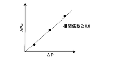
図22は、実製品90について表示された脈圧ΔPwと本願製品について表示された脈圧ΔPとの関係を示すグラフである。実製品90について構成Aを採用している場合、実製品90で測定された複数の脈圧ΔPw(ΔPw1,ΔPw2,ΔPw3)と本願製品で測定された複数の脈圧ΔP(ΔP1,ΔP2,ΔP3)との間には相関が観測される。具体的には、実製品90について表示された複数の脈圧ΔPwと、本願製品について表示された複数の脈圧ΔPとの相関係数が0.8以上になる。以上の事情を考慮して、実製品90に複数の試験信号Uを供給して算定された脈圧ΔPwと、本願製品に複数の試験信号Uを供給して算定された脈圧ΔPとの相関係数が0.8以上となる場合は、当該実製品90については構成Aを採用している可能性が充分に高い。なお、相関係数としては、例えばピアソンの積算相関係数が好適である。
FIG. 22 is a graph showing the relationship between the pulse pressure ΔPw displayed for the
なお、以上の説明では試験信号Uを実製品90の処理部93に供給したが、実製品90において検出信号を生成する受光部Rに、試験信号Uが生成されるような光を受光させ、これにより算定された脈圧ΔPwを本願製品の脈圧ΔPと対比してもよい。また、以上の説明では実製品90の表示装置95に表示される脈圧ΔPwと本願製品の表示装置に表示される脈圧ΔPとを対比したが、実製品90の処理部93から出力されるデータと本願製品の制御装置から出力されるデータとを対比することで実製品90における構成Aの有無を判断してもよい。
In the above description, the test signal U is supplied to the
以上の説明では実製品90が脈圧ΔPwを表示する場合を便宜的に想定したが、実製品90が被験者の血圧P(収縮期血圧Pmaxおよび拡張期血圧Pmin)を表示する場合も、同様の方法により、実製品90における構成Aの有無を推定することが可能である。すなわち、複数の試験信号Uを実製品90に順次に供給することで測定される複数の血圧Pと、複数の試験信号Uを本願製品(第5実施形態)に順次に供給することで測定される複数の血圧Pとの間の相関係数を算定する。相関係数が0.8以上である場合には、実製品90が構成Aを採用している可能性が高い。
In the above description, it is assumed for convenience that the
実製品90が被験者の抵抗指標を出力する場合には、血液量積算値SMと血流量積算値SFとの比を抵抗指標として算定する構成(以下「構成B」という)を実製品90が具備するか否かを、以上の説明と同様の方法により推定することが可能である。具体的には、血液量積算値SMと血流量積算値SFとの比(SF/SM)が異なる複数の試験信号Uを実製品90に供給することで算定される複数の比(SF/SM)と、複数の試験信号Uを本願製品に順次に供給することで測定される複数の比(SF/SM)との間の相関係数を算定する。相関係数が0.8以上である場合には、実製品90が構成Bを採用している可能性が高い。
When the
実製品90が被験者の振幅指標を出力する場合には、振幅ΔMと振幅ΔFとの比を振幅指標として算定する構成(以下「構成C」という)を実製品90が具備するか否かを、以上の説明と同様の方法により推定することが可能である。具体的には、振幅ΔMと振幅ΔFとの比(ΔF/ΔM)が異なる複数の試験信号Uを実製品90に供給することで算定される複数の比(ΔF/ΔM)と、複数の試験信号Uを本願製品に順次に供給することで算定される複数の比(ΔF/ΔM)との間の相関係数を算定する。相関係数が0.8以上である場合には、実製品90が構成Bを採用している可能性が高い。
When the
前述の通り、構成Cによれば、皮膚厚が変化した場合でも高精度に振幅指標を算定できるという効果が実現される。したがって、実製品90における構成Cの有無については、以下の方法でも推定される。まず、血液が流れる疑似血管が埋設された人体モデルを想定し、人体モデルの皮膚厚を変化させた複数の場合について、実製品90と本願製品とで振幅指標を算定する。実製品90で算定される複数の振幅指標と、本願製品で算定される複数の振幅指標との間の相関係数が0.8以上である場合には、実製品90が構成Cを採用している可能性が高い。また、実製品90および本願製品の各々について、発光部Eと受光部R間との距離を変化させた複数の場合について、実製品90と本願製品とで振幅指標を算定する。実製品90で算定される複数の振幅指標と、本願製品で算定される複数の振幅指標との間の相関係数が0.8以上である場合には、実製品90が構成Cを採用している可能性が高い。
As described above, according to the configuration C, the effect that the amplitude index can be calculated with high accuracy even when the skin thickness changes is realized. Therefore, the presence or absence of the configuration C in the
<変形例>
以上に例示した各形態は多様に変形され得る。具体的な変形の態様を以下に例示する。以下の例示から任意に選択された2以上の態様を適宜に併合することも可能である。
<Modification example>
Each of the above-exemplified forms can be variously modified. Specific modes of modification are illustrated below. It is also possible to appropriately merge two or more embodiments arbitrarily selected from the following examples.
(1)第1実施形態では、血液量積算値SMと血流量積算値SFとの比(SF/SM)を抵抗指標として算定したが、抵抗指標は以上の例示に限定されない。例えば脈波伝播速度PWVそのものを抵抗指標として算定することも可能である。図23は、変形例における生体解析装置100の構成図である。変形例における生体解析装置100は、第1実施形態の生体解析装置100に2つの検出装置30(30F,30G)を追加し、第1実施形態の抵抗算定部533に代えてPWV算定部537を具備する構成である。各検出装置30(30F,30G)は、例えば検出装置30Aと同様の光学式センサーモジュールであり、測定部位Hの状態を反映した検出信号Zを生成する。PWV算定部537は、検出装置30Fが生成した検出信号ZFと検出信号30Gが生成した検出信号ZGとを利用して、脈波伝播速度PWVを抵抗指標として算定する。脈圧算定部535は、振幅算定部531が算定した振幅指標と、PWV算定部537が算定した抵抗指標とに応じて脈圧ΔPを算定する。なお、第2実施形態,第3実施形態および第5実施形態についても、以上の変形例は適用し得る。
(1) In the first embodiment, the ratio (SF / SM) of the integrated blood flow rate SM and the integrated blood flow rate SF is calculated as a resistance index, but the resistance index is not limited to the above examples. For example, the pulse wave velocity PWV itself can be calculated as a resistance index. FIG. 23 is a configuration diagram of the
(2)前述の各形態では、血管算定部53は脈圧ΔPを算定したが、血管算定部53が算定する指標は脈圧ΔPに限定されない。例えば、算定した脈圧ΔPを利用して、血管算定部53が、被験者の脈圧ΔPの状態を示す指標(例えば、異常/高目/通常、など)を特定してもよい。以上の説明から理解される通り、血管算定部53が算定する指標は、脈圧ΔPに関する指標(以下「脈圧指標」という)として包括的に表現され、脈圧指標には、脈圧ΔPそのものと脈圧ΔPを利用して算定される指標との双方を含む。
(2) In each of the above-mentioned forms, the blood
また、血管算定部53が脈圧指標以外の指標を算定してもよい。ここで、動脈硬化が進行すると血管抵抗が大きくなるという傾向がある。前述の通り、抵抗指標は血管抵抗に相関するので、動脈硬化の指標としても抵抗指標を利用することができる。そこで、血管算定部53が算定した抵抗指標を利用者に提示してもよい。具体的には、血管抵抗部は、血液量積算値SMと血流量積算値SFとに応じて抵抗指標を算定し(比(SF/SM)を抵抗指標として算定し)、当該抵抗指標を表示装置23に表示させる。また、血管算定部53は、比(SF/SM)を算定し、当該比(SF/SM)から脈波伝播速度PWVを抵抗指標として算定してもよい。また、血管算定部53は、算定した比(SF/SM)または脈波伝播速度PWVから、例えば動脈硬化の度合を示す指標を抵抗指標として算定してもよい。すなわち、抵抗指標は、生体の血管抵抗に関する指標として包括的に表現される。以上の説明から理解される通り、血管算定部53が算定する指標は、血管に関する指標(以下「血管指標」という)として包括的に表現され、血管指標には脈圧指標と抵抗指標との双方が含まれる。つまり、血管算定部53は、血液量積算値SMと血流量積算値SFとに応じて(典型的には血液量積算値SMと血流量積算値SFとの比に応じて)血管指標を算定する要素として機能する。
Further, the blood
また、血管算定部53が振幅指標を算定し、当該振幅指標を表示装置23に表示させてもよい。以上の説明から理解される通り、血管算定部53が算定した振幅指標と抵抗指標とは、独立した指標として被験者に提示してもよい。振幅指標または抵抗指標を独立した指標として算定する構成においても、原理的にカフが不要であるので、被験者の身体的な負荷を軽減しながら、各指標を高精度に算定することが可能である。
Further, the blood
(3)第1実施形態では、血液量積算値SMと血流量積算値SFとの比(SF/SM)を抵抗指標として算定したが、抵抗指標として算定する値は比(SF/SM)に限定されない。例えば比(SF/SM)を所定の関数に代入して抵抗指標を算定する構成、または、比(SF/SM)に係数を乗算することで抵抗指標を算定する構成も採用され得る。また、例えば血液量積算値SMと血流量積算値SFとの差を抵抗指標として算定する構成も採用され得る。ただし、血液量積算値SMと血流量積算値SFとの比を利用して抵抗指標を算定する構成によれば、血液量積算値SMと血流量積算値SFとの比が脈波伝播速度と相関するという傾向を利用して、高精度に抵抗指標を算定することができる。なお、第2実施形態,第3実施形態および第5実施形態についても、以上の変形例は適用し得る。 (3) In the first embodiment, the ratio (SF / SM) of the integrated blood volume value SM and the integrated blood flow value SF is calculated as the resistance index, but the value calculated as the resistance index is the ratio (SF / SM). Not limited. For example, a configuration in which the ratio (SF / SM) is substituted into a predetermined function to calculate the resistance index, or a configuration in which the ratio (SF / SM) is multiplied by a coefficient to calculate the resistance index can be adopted. Further, for example, a configuration in which the difference between the integrated blood flow rate SM and the integrated blood flow rate SF is calculated as a resistance index can be adopted. However, according to the configuration in which the resistance index is calculated using the ratio of the blood volume integrated value SM and the blood flow integrated value SF, the ratio of the blood volume integrated value SM and the blood flow integrated value SF is the pulse wave velocity. The resistance index can be calculated with high accuracy by using the tendency of correlation. The above modifications can be applied to the second embodiment, the third embodiment, and the fifth embodiment.
(4)第1実施形態では、振幅ΔFと振幅ΔMとの比(ΔF/ΔM)を振幅指標として算定したが、振幅指標として算定する値は比(ΔF/ΔM)に限定されない。例えば比(ΔF/ΔM)を所定の関数に代入して振幅指標を算定する構成、または、比(ΔF/ΔM)に係数を乗算することで振幅指標を算定する構成も採用され得る。また、例えば振幅ΔFと振幅ΔMとの差を振幅指標として算定する構成も採用され得る。ただし、振幅ΔFと振幅ΔMとの比を利用して振幅指標を算定する構成によれば、振幅ΔMと振幅ΔFとの比(ΔF/ΔM)と血流速度とが相関する傾向を利用して、高精度に振幅指標を算定することができる。また、皮膚厚の影響を低減しながら振幅指標を算定することができる。 (4) In the first embodiment, the ratio (ΔF / ΔM) of the amplitude ΔF and the amplitude ΔM is calculated as the amplitude index, but the value calculated as the amplitude index is not limited to the ratio (ΔF / ΔM). For example, a configuration in which the ratio (ΔF / ΔM) is substituted into a predetermined function to calculate the amplitude index, or a configuration in which the ratio (ΔF / ΔM) is multiplied by a coefficient to calculate the amplitude index can be adopted. Further, for example, a configuration in which the difference between the amplitude ΔF and the amplitude ΔM is calculated as an amplitude index can be adopted. However, according to the configuration in which the amplitude index is calculated using the ratio of the amplitude ΔF and the amplitude ΔM, the tendency that the ratio (ΔF / ΔM) between the amplitude ΔM and the amplitude ΔF and the blood flow velocity correlate is used. , The amplitude index can be calculated with high accuracy. In addition, the amplitude index can be calculated while reducing the influence of the skin thickness.
(5)前述の各形態では、1つの解析期間Tにおける血液量指標Mの時間変化MTを脈圧ΔPの算定に利用したが、複数の解析期間Tの各々における血液量指標Mの時間変化MTを複数の解析期間Tにわたり平均した時間変化MTを脈圧ΔPの算定に利用してもよい。なお、血流量指標Fについても、複数の解析期間Tの各々における血流量指標Fの時間変化FTを複数の解析期間Tにわたり平均した時間変化FTを脈圧ΔPの算定に利用してもよい。 (5) In each of the above-mentioned forms, the time-varying MT of the blood volume index M in one analysis period T was used for calculating the pulse pressure ΔP, but the time-varying MT of the blood volume index M in each of the plurality of analysis periods T. The time-varying MT averaged over a plurality of analysis periods T may be used to calculate the pulse pressure ΔP. As for the blood flow index F, the time change FT obtained by averaging the time change FT of the blood flow index F in each of the plurality of analysis periods T over the plurality of analysis periods T may be used for calculating the pulse pressure ΔP.
(6)第1実施形態では、血液量指標MAおよび血流量指標FAの各々を、0以上1以下の正規化範囲に正規化したが、血液量指標MAおよび血流量指標FAが共通の範囲で正規化されれば正規化範囲の上限値および下限値は任意である。なお、第2実施形態,第3実施形態および第5実施形態についても、以上の変形例は適用し得る。 (6) In the first embodiment, each of the blood volume index MA and the blood flow index FA is normalized to the normalization range of 0 or more and 1 or less, but the blood volume index MA and the blood flow index FA are in the common range. Once normalized, the upper and lower limits of the normalization range are arbitrary. The above modifications can be applied to the second embodiment, the third embodiment, and the fifth embodiment.
(7)前述の各形態では、単体の機器として構成された生体解析装置100を例示したが、以下の例示の通り、生体解析装置100の複数の要素は相互に別体の装置として実現され得る。なお、以下の説明では、検出信号ZAから脈圧ΔPを算定する要素を「演算処理部27」と表記する。演算処理部27は、例えば、図3に例示された要素(指標算定部51および血管算定部53)を包含する。
(7) In each of the above-described embodiments, the
前述の各形態では、検出装置30(30A,30B,30C,30D,30E)を具備する生体解析装置100を例示したが、図24に例示される通り、検出装置30を生体解析装置100とは別体とした構成も想定される。検出装置30は、例えば被験者の手首や上腕等の測定部位Hに装着される可搬型の光学センサーモジュールである。生体解析装置100は、例えば携帯電話機またはスマートフォン等の情報端末で実現される。腕時計型の情報端末で生体解析装置100を実現してもよい。検出装置30が生成した検出信号Zが有線または無線で生体解析装置100に送信される。生体解析装置100の演算処理部27は、検出信号Zから脈圧ΔPを算定して表示装置23に表示する。以上の説明から理解される通り、検出装置30は生体解析装置100から省略され得る。
In each of the above-described embodiments, the
前述の各形態では、表示装置23を具備する生体解析装置100を例示したが、図25に例示される通り、表示装置23を生体解析装置100とは別体とした構成も想定される。生体解析装置100の演算処理部27は、検出信号Zから脈圧ΔPを算定し、当該脈圧ΔPを表示するためのデータを表示装置23に送信する。表示装置23は、専用の表示機器であってもよいが、例えば、携帯電話機もしくはスマートフォン等の情報端末、または、被験者が携帯可能な腕時計型の情報端末に搭載されてもよい。生体解析装置100の演算処理部27が算定した脈圧ΔPは、有線または無線により表示装置23に送信される。表示装置23は、生体解析装置100から受信した脈圧ΔPを表示する。以上の説明から理解される通り、表示装置23は生体解析装置100から省略され得る。
In each of the above-described embodiments, the
図26に例示される通り、検出装置30および表示装置23を生体解析装置100(演算処理部27)とは別体とした構成も想定される。例えば、生体解析装置100(演算処理部27)が、携帯電話機やスマートフォン等の情報端末に搭載される。
As illustrated in FIG. 26, it is assumed that the
なお、検出装置30と生体解析装置100とを別体とした構成において、指標算定部51を検出装置30に搭載することも可能である。指標算定部51が算定した血液量指標Mおよび血流量指標Fが有線または無線により検出装置30Aから生体解析装置100に送信される。以上の説明から理解される通り、指標算定部51は生体解析装置100から省略され得る。
It is also possible to mount the index calculation unit 51 on the
(8)前述の各形態では、筐体部12とベルト14とを具備する腕時計型の生体解析装置100を例示したが、生体解析装置100の具体的な形態は任意である。例えば、被験者の身体に貼付可能なパッチ型、被験者の耳部に装着可能な耳装着型、被験者の指先に装着可能な指装着型(例えば着爪型)、または、被験者の頭部に装着可能な頭部装着型など、任意の形態の生体解析装置100が採用され得る。
(8) In each of the above-described embodiments, the wristwatch-
(9)前述の各形態では、被験者の脈圧ΔPを表示装置23に表示したが、脈圧ΔPを被験者に報知するための構成は以上の例示に限定されない。例えば、脈圧ΔPを音声で被験者に報知することも可能である。被験者の耳部に装着可能な耳装着型の生体解析装置100においては、脈圧ΔPを音声で報知する構成が特に好適である。また、脈圧ΔPを被験者に報知することは必須ではない。例えば、生体解析装置100が算定した脈圧ΔPを通信網から他の通信装置に送信してもよい。また、生体解析装置100の記憶装置22や生体解析装置100に着脱可能な可搬型の記録媒体に脈圧ΔPを格納してもよい。
(9) In each of the above-described embodiments, the pulse pressure ΔP of the subject is displayed on the
(10)前述の各形態に係る生体解析装置100は、前述の例示の通り、制御装置21とプログラムとの協働により実現される。本発明の好適な態様に係るプログラムは、コンピューターが読取可能な記録媒体に格納された形態で提供されてコンピューターにインストールされ得る。また、配信サーバーが具備する記録媒体に格納されたプログラムを、通信網を介した配信の形態でコンピューターに提供することも可能である。記録媒体は、例えば非一過性(non-transitory)の記録媒体であり、CD-ROM等の光学式記録媒体(光ディスク)が好例であるが、半導体記録媒体または磁気記録媒体等の公知の任意の形式の記録媒体を包含し得る。なお、非一過性の記録媒体とは、一過性の伝搬信号(transitory, propagating signal)を除く任意の記録媒体を含み、揮発性の記録媒体を除外するものではない。
(10) The
100…生体解析装置、12…筐体部、14…ベルト、21…制御装置、22…記憶装置、23…表示装置、27…演算処理部、30…検出装置、51…指標算定部、53…血管算定部、55…平均血圧算定部、57…血圧算定部、531…振幅算定部、533…抵抗算定部、535…脈圧算定部、537…PWV算定部、71…検出ユニット、72…表示ユニット、90…実製品、91…検出装置、93…処理部、E…発光部、ED…発信部、R…受光部、RD…受信部。 100 ... Bioanalysis device, 12 ... Housing unit, 14 ... Belt, 21 ... Control device, 22 ... Storage device, 23 ... Display device, 27 ... Arithmetic processing unit, 30 ... Detection device, 51 ... Index calculation unit, 53 ... Blood vessel calculation unit, 55 ... mean blood pressure calculation unit, 57 ... blood pressure calculation unit, 513 ... amplitude calculation unit, 533 ... resistance calculation unit, 535 ... pulse pressure calculation unit, 537 ... PWV calculation unit, 71 ... detection unit, 72 ... display Unit, 90 ... actual product, 91 ... detection device, 93 ... processing unit, E ... light emitting unit, ED ... transmitting unit, R ... light receiving unit, RD ... receiving unit.
Claims (12)
を具備する生体解析装置。 The blood volume index related to the blood volume of the living body is integrated for the integrated period corresponding to one beat of the pulsation of the living body, and the blood volume index related to the blood flow volume of the living body is integrated for the integrated period. A biological analysis device provided with a blood vessel calculation unit that calculates a blood vessel index related to the blood vessel of the living body according to the integrated flow rate value.
請求項1の生体解析装置。 The bioanalytical device according to claim 1, which calculates the blood vessel index according to the ratio of the integrated blood volume value to the integrated blood volume value.
請求項1または請求項2の生体解析装置。 The blood vessel index is the bioanalytical device according to claim 1 or 2, which is a pulse pressure index related to pulse pressure.
前記血管算定部は、
前記血液量指標の時間変化の振幅と前記血流量指標の時間変化の振幅との比を、前記生体の血流速度の時間変化の振幅に関する振幅指標として算定する振幅算定部と、
前記血液量積算値と前記血流量積算値との比を、前記生体の血管抵抗に関する抵抗指標として算定する抵抗算定部と、
前記振幅指標と前記抵抗指標とに応じた前記脈圧指標を算定する脈圧算定部とを含む
生体解析装置。 The pulse pressure of the living body according to the integrated blood volume value obtained by accumulating the blood volume index related to the blood volume of the living body for the integration period and the integrated blood volume index obtained by accumulating the blood flow index relating to the blood flow volume of the living body for the integration period. Equipped with a blood vessel calculation unit that calculates the pulse pressure index for
The blood vessel calculation unit
An amplitude calculation unit that calculates the ratio of the time change amplitude of the blood volume index to the time change amplitude of the blood flow index as an amplitude index relating to the time change amplitude of the blood flow velocity of the living body.
A resistance calculation unit that calculates the ratio of the blood volume integrated value and the blood flow integrated value as a resistance index related to the vascular resistance of the living body.
A bioanalyzer including a pulse pressure calculation unit that calculates the pulse pressure index according to the amplitude index and the resistance index.
請求項4の生体解析装置。 The resistance calculation unit calculates the blood volume integrated value obtained by integrating the value obtained by normalizing the blood volume index within the normalized range for the integration period, and the value obtained by normalizing the blood flow index within the normalized range. The bioanalyzer according to claim 4, wherein the ratio with the integrated blood flow value integrated for the integration period is calculated as the resistance index.
請求項1または請求項2の生体解析装置。 The blood vessel index is the biological analysis device according to claim 1 or 2, which is a resistance index relating to the vascular resistance of the living body.
請求項1から請求項6の何れかの生体解析装置。 The biological analysis device according to any one of claims 1 to 6, which is attached to the upper arm or wrist of the living body.
前記生体の内部で反射した前記レーザー光を受光する受光部と、
前記受光部による受光レベルを表す検出信号を利用して、前記生体の血液量に関する血液量指標と、前記生体の血流量に関する血流量指標とを算定する指標算定部と、
前記血液量指標を積算期間について積算した血液量積算値と、前記血流量指標を前記積算期間について積算した血流量積算値とに応じて、前記生体の血管に関する血管指標を算定する血管算定部と
を具備する生体解析装置。 A light emitting part that irradiates a living body with laser light,
A light receiving unit that receives the laser beam reflected inside the living body, and a light receiving portion.
An index calculation unit that calculates a blood volume index relating to the blood volume of the living body and a blood flow index relating to the blood flow volume of the living body by using a detection signal indicating the light receiving level by the light receiving unit.
A blood vessel calculation unit that calculates a blood vessel index related to a blood vessel of a living body according to a blood volume integrated value obtained by integrating the blood volume index for an integrated period and a blood vessel integrated value obtained by accumulating the blood volume index for the integrated period. A bioanalyzer equipped with.
前記生体の内部で反射した前記レーザー光を受光する受光部と、
前記受光部による受光レベルを表す検出信号を利用して、前記生体の血液量に関する血液量指標と、前記生体の血流量に関する血流量指標とを算定する指標算定部と、
前記血液量指標を積算期間について積算した血液量積算値と、前記血流量指標を前記積算期間について積算した血流量積算値とに応じて、前記生体の血管に関する血管指標を算定する血管算定部とを具備し、
前記指標算定部は、
前記検出信号の周波数に関する強度スペクトルにおける各周波数の強度を所定の周波数範囲について積算して前記血液量指標を算定する
生体解析装置。 A light emitting part that irradiates a living body with laser light,
A light receiving unit that receives the laser beam reflected inside the living body, and a light receiving portion.
An index calculation unit that calculates a blood volume index relating to the blood volume of the living body and a blood flow index relating to the blood flow volume of the living body by using a detection signal indicating the light receiving level by the light receiving unit.
A blood vessel calculation unit that calculates a blood vessel index related to a blood vessel of a living body according to a blood volume integrated value obtained by integrating the blood volume index for an integrated period and a blood vessel integrated value obtained by accumulating the blood volume index for the integrated period. Equipped with
The index calculation unit
A bioanalyzer that calculates the blood volume index by integrating the intensities of each frequency in the intensity spectrum with respect to the frequency of the detection signal for a predetermined frequency range.
前記検出信号の周波数に関する強度スペクトルにおける各周波数の強度と当該周波数との積を所定の周波数範囲について積算して前記血流量指標を算定する
請求項8または請求項9の生体解析装置。 The index calculation unit
The bioanalyzer according to claim 8 or 9, wherein the product of the intensity of each frequency in the intensity spectrum relating to the frequency of the detection signal and the frequency is integrated over a predetermined frequency range to calculate the blood flow index.
生体解析方法。 The blood volume index related to the blood volume of the living body is integrated for the integrated period corresponding to one beat of the pulsation of the living body, and the blood volume index related to the blood flow volume of the living body is integrated for the integrated period. A biological analysis method for calculating a blood vessel index relating to a blood vessel of the living body according to the ratio with the integrated flow rate value.
としてコンピューターを機能させるプログラム。
The blood volume index related to the blood volume of the living body is integrated for the integrated period corresponding to one beat of the pulsation of the living body, and the blood volume index related to the blood flow volume of the living body is integrated for the integrated period. A program that makes a computer function as a blood vessel calculation unit that calculates blood vessel indexes related to the blood vessels of the living body according to the ratio with the integrated flow rate.
Priority Applications (2)
| Application Number | Priority Date | Filing Date | Title |
|---|---|---|---|
| JP2017157160A JP7087301B2 (en) | 2017-08-16 | 2017-08-16 | Bioanalyzers, bioanalysis methods and programs |
| US15/998,546 US11116414B2 (en) | 2017-08-16 | 2018-08-16 | Biological analysis device, biological analysis method, and program |
Applications Claiming Priority (1)
| Application Number | Priority Date | Filing Date | Title |
|---|---|---|---|
| JP2017157160A JP7087301B2 (en) | 2017-08-16 | 2017-08-16 | Bioanalyzers, bioanalysis methods and programs |
Publications (2)
| Publication Number | Publication Date |
|---|---|
| JP2019033901A JP2019033901A (en) | 2019-03-07 |
| JP7087301B2 true JP7087301B2 (en) | 2022-06-21 |
Family
ID=65636304
Family Applications (1)
| Application Number | Title | Priority Date | Filing Date |
|---|---|---|---|
| JP2017157160A Active JP7087301B2 (en) | 2017-08-16 | 2017-08-16 | Bioanalyzers, bioanalysis methods and programs |
Country Status (1)
| Country | Link |
|---|---|
| JP (1) | JP7087301B2 (en) |
Citations (4)
| Publication number | Priority date | Publication date | Assignee | Title |
|---|---|---|---|---|
| JP2002200052A (en) | 2000-12-28 | 2002-07-16 | Fukuda Denshi Co Ltd | Vascular endothelium function tester |
| JP2008114037A (en) | 2006-10-12 | 2008-05-22 | Nippon Telegr & Teleph Corp <Ntt> | Blood pressure measuring apparatus and control method for blood pressure measuring apparatus |
| WO2012142455A2 (en) | 2011-04-14 | 2012-10-18 | Regents Of The University Of Minnesota | Vascular characterization using ultrasound imaging |
| JP2016146958A (en) | 2015-02-12 | 2016-08-18 | セイコーエプソン株式会社 | Blood pressure measuring device and blood pressure measuring method |
-
2017
- 2017-08-16 JP JP2017157160A patent/JP7087301B2/en active Active
Patent Citations (4)
| Publication number | Priority date | Publication date | Assignee | Title |
|---|---|---|---|---|
| JP2002200052A (en) | 2000-12-28 | 2002-07-16 | Fukuda Denshi Co Ltd | Vascular endothelium function tester |
| JP2008114037A (en) | 2006-10-12 | 2008-05-22 | Nippon Telegr & Teleph Corp <Ntt> | Blood pressure measuring apparatus and control method for blood pressure measuring apparatus |
| WO2012142455A2 (en) | 2011-04-14 | 2012-10-18 | Regents Of The University Of Minnesota | Vascular characterization using ultrasound imaging |
| JP2016146958A (en) | 2015-02-12 | 2016-08-18 | セイコーエプソン株式会社 | Blood pressure measuring device and blood pressure measuring method |
Also Published As
| Publication number | Publication date |
|---|---|
| JP2019033901A (en) | 2019-03-07 |
Similar Documents
| Publication | Publication Date | Title |
|---|---|---|
| US11116414B2 (en) | Biological analysis device, biological analysis method, and program | |
| JP6597410B2 (en) | Biological information measuring device and biological information measuring method | |
| KR102299361B1 (en) | Apparatus and method for monitoring blood pressure, wearable device having function of blood pressure monitoring | |
| US20190053767A1 (en) | Biological analysis device, biological analysis method, and program | |
| US20130109947A1 (en) | Methods and systems for continuous non-invasive blood pressure measurement using photoacoustics | |
| US20170251930A1 (en) | Biological information measurement apparatus and biological information measurement method | |
| US11179045B2 (en) | Blood pressure measurement device and blood pressure measurement method | |
| US10058273B2 (en) | Detection device and measuring apparatus | |
| JP7087301B2 (en) | Bioanalyzers, bioanalysis methods and programs | |
| JP7069598B2 (en) | Bioanalyzers, bioanalysis methods and programs | |
| US10772513B2 (en) | Blood pressure ratio calculation device, blood pressure ratio calculation method, blood pressure ratio calculation program, and recording medium recording said program | |
| JP2019187637A (en) | Living body analysis apparatus, living body analysis method, and program | |
| JP7135449B2 (en) | Biological analysis device, biological analysis method and program | |
| JP7124460B2 (en) | Biological analysis device, biological analysis method and program | |
| US20180303429A1 (en) | Blood flow analyzer, blood flow analysis method, and program | |
| US11253205B2 (en) | Pulse pressure and blood pressure analysis device, pulse pressure and blood pressure analysis method, and program | |
| JP7187824B2 (en) | Biological analysis device, biological analysis method and program | |
| JP2019033900A (en) | Organism analyzer, organism analysis method and program | |
| JP6996157B2 (en) | Bioanalyzers, bioanalysis methods and programs | |
| JP6996220B2 (en) | Bioanalyzers, bioanalysis methods and programs | |
| JP2018029870A (en) | Detection device and detection method | |
| JP2019115549A (en) | Living body analysis device, living body analysis method, and program | |
| JP6825341B2 (en) | Measuring device, blood pressure measuring device and measuring method | |
| US20170172416A1 (en) | Biological information acquisition apparatus and biological information acquisition method | |
| JP6996224B2 (en) | Blood flow analyzer, blood flow analysis method and program |
Legal Events
| Date | Code | Title | Description |
|---|---|---|---|
| A621 | Written request for application examination |
Free format text: JAPANESE INTERMEDIATE CODE: A621 Effective date: 20200713 |
|
| A977 | Report on retrieval |
Free format text: JAPANESE INTERMEDIATE CODE: A971007 Effective date: 20210521 |
|
| A131 | Notification of reasons for refusal |
Free format text: JAPANESE INTERMEDIATE CODE: A131 Effective date: 20210608 |
|
| A521 | Request for written amendment filed |
Free format text: JAPANESE INTERMEDIATE CODE: A523 Effective date: 20210730 |
|
| A131 | Notification of reasons for refusal |
Free format text: JAPANESE INTERMEDIATE CODE: A131 Effective date: 20211214 |
|
| A521 | Request for written amendment filed |
Free format text: JAPANESE INTERMEDIATE CODE: A523 Effective date: 20220127 |
|
| TRDD | Decision of grant or rejection written | ||
| A01 | Written decision to grant a patent or to grant a registration (utility model) |
Free format text: JAPANESE INTERMEDIATE CODE: A01 Effective date: 20220510 |
|
| A61 | First payment of annual fees (during grant procedure) |
Free format text: JAPANESE INTERMEDIATE CODE: A61 Effective date: 20220523 |
|
| R150 | Certificate of patent or registration of utility model |
Ref document number: 7087301 Country of ref document: JP Free format text: JAPANESE INTERMEDIATE CODE: R150 |