JP7086962B2 - Ultrasonic surgical instrument with transducer slip joint - Google Patents
Ultrasonic surgical instrument with transducer slip joint Download PDFInfo
- Publication number
- JP7086962B2 JP7086962B2 JP2019531711A JP2019531711A JP7086962B2 JP 7086962 B2 JP7086962 B2 JP 7086962B2 JP 2019531711 A JP2019531711 A JP 2019531711A JP 2019531711 A JP2019531711 A JP 2019531711A JP 7086962 B2 JP7086962 B2 JP 7086962B2
- Authority
- JP
- Japan
- Prior art keywords
- proximal
- transducer
- junction
- distal
- assembly
- Prior art date
- Legal status (The legal status is an assumption and is not a legal conclusion. Google has not performed a legal analysis and makes no representation as to the accuracy of the status listed.)
- Active
Links
Images


Classifications
-
- A—HUMAN NECESSITIES
- A61—MEDICAL OR VETERINARY SCIENCE; HYGIENE
- A61B—DIAGNOSIS; SURGERY; IDENTIFICATION
- A61B17/00—Surgical instruments, devices or methods, e.g. tourniquets
- A61B17/32—Surgical cutting instruments
- A61B17/320068—Surgical cutting instruments using mechanical vibrations, e.g. ultrasonic
-
- A—HUMAN NECESSITIES
- A61—MEDICAL OR VETERINARY SCIENCE; HYGIENE
- A61B—DIAGNOSIS; SURGERY; IDENTIFICATION
- A61B17/00—Surgical instruments, devices or methods, e.g. tourniquets
- A61B17/00234—Surgical instruments, devices or methods, e.g. tourniquets for minimally invasive surgery
-
- A—HUMAN NECESSITIES
- A61—MEDICAL OR VETERINARY SCIENCE; HYGIENE
- A61B—DIAGNOSIS; SURGERY; IDENTIFICATION
- A61B17/00—Surgical instruments, devices or methods, e.g. tourniquets
- A61B17/28—Surgical forceps
- A61B17/29—Forceps for use in minimally invasive surgery
-
- A—HUMAN NECESSITIES
- A61—MEDICAL OR VETERINARY SCIENCE; HYGIENE
- A61B—DIAGNOSIS; SURGERY; IDENTIFICATION
- A61B17/00—Surgical instruments, devices or methods, e.g. tourniquets
- A61B17/32—Surgical cutting instruments
- A61B17/320068—Surgical cutting instruments using mechanical vibrations, e.g. ultrasonic
- A61B17/320092—Surgical cutting instruments using mechanical vibrations, e.g. ultrasonic with additional movable means for clamping or cutting tissue, e.g. with a pivoting jaw
-
- A—HUMAN NECESSITIES
- A61—MEDICAL OR VETERINARY SCIENCE; HYGIENE
- A61B—DIAGNOSIS; SURGERY; IDENTIFICATION
- A61B18/00—Surgical instruments, devices or methods for transferring non-mechanical forms of energy to or from the body
- A61B18/04—Surgical instruments, devices or methods for transferring non-mechanical forms of energy to or from the body by heating
-
- A—HUMAN NECESSITIES
- A61—MEDICAL OR VETERINARY SCIENCE; HYGIENE
- A61B—DIAGNOSIS; SURGERY; IDENTIFICATION
- A61B90/00—Instruments, implements or accessories specially adapted for surgery or diagnosis and not covered by any of the groups A61B1/00 - A61B50/00, e.g. for luxation treatment or for protecting wound edges
- A61B90/03—Automatic limiting or abutting means, e.g. for safety
-
- A—HUMAN NECESSITIES
- A61—MEDICAL OR VETERINARY SCIENCE; HYGIENE
- A61N—ELECTROTHERAPY; MAGNETOTHERAPY; RADIATION THERAPY; ULTRASOUND THERAPY
- A61N7/00—Ultrasound therapy
- A61N7/02—Localised ultrasound hyperthermia
-
- A—HUMAN NECESSITIES
- A61—MEDICAL OR VETERINARY SCIENCE; HYGIENE
- A61B—DIAGNOSIS; SURGERY; IDENTIFICATION
- A61B17/00—Surgical instruments, devices or methods, e.g. tourniquets
- A61B2017/00477—Coupling
-
- A—HUMAN NECESSITIES
- A61—MEDICAL OR VETERINARY SCIENCE; HYGIENE
- A61B—DIAGNOSIS; SURGERY; IDENTIFICATION
- A61B17/00—Surgical instruments, devices or methods, e.g. tourniquets
- A61B17/32—Surgical cutting instruments
- A61B17/320068—Surgical cutting instruments using mechanical vibrations, e.g. ultrasonic
- A61B2017/320069—Surgical cutting instruments using mechanical vibrations, e.g. ultrasonic for ablating tissue
-
- A—HUMAN NECESSITIES
- A61—MEDICAL OR VETERINARY SCIENCE; HYGIENE
- A61B—DIAGNOSIS; SURGERY; IDENTIFICATION
- A61B17/00—Surgical instruments, devices or methods, e.g. tourniquets
- A61B17/32—Surgical cutting instruments
- A61B17/320068—Surgical cutting instruments using mechanical vibrations, e.g. ultrasonic
- A61B2017/320071—Surgical cutting instruments using mechanical vibrations, e.g. ultrasonic with articulating means for working tip
-
- A—HUMAN NECESSITIES
- A61—MEDICAL OR VETERINARY SCIENCE; HYGIENE
- A61B—DIAGNOSIS; SURGERY; IDENTIFICATION
- A61B17/00—Surgical instruments, devices or methods, e.g. tourniquets
- A61B17/32—Surgical cutting instruments
- A61B17/320068—Surgical cutting instruments using mechanical vibrations, e.g. ultrasonic
- A61B17/320092—Surgical cutting instruments using mechanical vibrations, e.g. ultrasonic with additional movable means for clamping or cutting tissue, e.g. with a pivoting jaw
- A61B2017/320094—Surgical cutting instruments using mechanical vibrations, e.g. ultrasonic with additional movable means for clamping or cutting tissue, e.g. with a pivoting jaw additional movable means performing clamping operation
-
- A—HUMAN NECESSITIES
- A61—MEDICAL OR VETERINARY SCIENCE; HYGIENE
- A61B—DIAGNOSIS; SURGERY; IDENTIFICATION
- A61B17/00—Surgical instruments, devices or methods, e.g. tourniquets
- A61B17/32—Surgical cutting instruments
- A61B17/320068—Surgical cutting instruments using mechanical vibrations, e.g. ultrasonic
- A61B17/320092—Surgical cutting instruments using mechanical vibrations, e.g. ultrasonic with additional movable means for clamping or cutting tissue, e.g. with a pivoting jaw
- A61B2017/320095—Surgical cutting instruments using mechanical vibrations, e.g. ultrasonic with additional movable means for clamping or cutting tissue, e.g. with a pivoting jaw with sealing or cauterizing means
-
- A—HUMAN NECESSITIES
- A61—MEDICAL OR VETERINARY SCIENCE; HYGIENE
- A61B—DIAGNOSIS; SURGERY; IDENTIFICATION
- A61B18/00—Surgical instruments, devices or methods for transferring non-mechanical forms of energy to or from the body
- A61B2018/00315—Surgical instruments, devices or methods for transferring non-mechanical forms of energy to or from the body for treatment of particular body parts
- A61B2018/00345—Vascular system
-
- A—HUMAN NECESSITIES
- A61—MEDICAL OR VETERINARY SCIENCE; HYGIENE
- A61B—DIAGNOSIS; SURGERY; IDENTIFICATION
- A61B18/00—Surgical instruments, devices or methods for transferring non-mechanical forms of energy to or from the body
- A61B2018/00571—Surgical instruments, devices or methods for transferring non-mechanical forms of energy to or from the body for achieving a particular surgical effect
- A61B2018/00601—Cutting
-
- A—HUMAN NECESSITIES
- A61—MEDICAL OR VETERINARY SCIENCE; HYGIENE
- A61B—DIAGNOSIS; SURGERY; IDENTIFICATION
- A61B18/00—Surgical instruments, devices or methods for transferring non-mechanical forms of energy to or from the body
- A61B2018/00571—Surgical instruments, devices or methods for transferring non-mechanical forms of energy to or from the body for achieving a particular surgical effect
- A61B2018/00619—Welding
-
- A—HUMAN NECESSITIES
- A61—MEDICAL OR VETERINARY SCIENCE; HYGIENE
- A61B—DIAGNOSIS; SURGERY; IDENTIFICATION
- A61B18/00—Surgical instruments, devices or methods for transferring non-mechanical forms of energy to or from the body
- A61B2018/00571—Surgical instruments, devices or methods for transferring non-mechanical forms of energy to or from the body for achieving a particular surgical effect
- A61B2018/0063—Sealing
-
- A—HUMAN NECESSITIES
- A61—MEDICAL OR VETERINARY SCIENCE; HYGIENE
- A61B—DIAGNOSIS; SURGERY; IDENTIFICATION
- A61B90/00—Instruments, implements or accessories specially adapted for surgery or diagnosis and not covered by any of the groups A61B1/00 - A61B50/00, e.g. for luxation treatment or for protecting wound edges
- A61B90/03—Automatic limiting or abutting means, e.g. for safety
- A61B2090/031—Automatic limiting or abutting means, e.g. for safety torque limiting
Description
様々な外科用器具が、組織を(例えば、組織細胞内のタンパク質を変性させることにより)切断及び/又は封止するために、超音波周波数で振動するブレード要素を有するエンドエフェクタを含む。これらの器具は、電力を超音波振動に変換する圧電素子を含んでおり、それらの振動は音波導波管に沿ってブレード要素に伝達される。切断及び凝固の精度は、外科医の技術、並びに電力レベル、ブレードエッジ、組織引張、及びブレード圧力を調節することによって制御され得る。 Various surgical instruments include end effectors with blade elements that vibrate at ultrasonic frequencies to cut and / or seal tissue (eg, by denaturing proteins in tissue cells). These instruments include piezoelectric elements that convert electric power into ultrasonic vibrations, which are transmitted to the blade elements along the sonic waveguide. The accuracy of cutting and coagulation can be controlled by the surgeon's technique and by adjusting the power level, blade edge, tissue tension, and blade pressure.
超音波外科用器具の例としては、HARMONIC ACE(登録商標)Ultrasonic Shears、HARMONIC WAVE(登録商標)Ultrasonic Shears、HARMONIC FOCUS(登録商標)Ultrasonic Shears、及びHARMONIC SYNERGY(登録商標)Ultrasonic Bladesが挙げられ、これらはいずれもEthicon Endo-Surgery,Inc.(Cincinnati,Ohio)製である。そのようなデバイス及び関連する概念の更なる例は、その開示が本明細書に参照により組み込まれる、米国特許第5,322,055号、名称「Clamp Coagulator/Cutting System for Ultrasonic Surgical Instruments」(1994年6月21日発行);その開示が本明細書に参照により組み込まれる、米国特許第5,873,873号、名称「Ultrasonic Clamp Coagulator Apparatus Having Improved Clamp Mechanism」(1999年2月23日発行);その開示が参照により本明細書に組み込まれる、米国特許第5,980,510号、名称「Ultrasonic Clamp Coagulator Apparatus Having Improved Clamp Arm Pivot Mount」(1997年10月10日発行);その開示が本明細書に参照により組み込まれる、米国特許第6,325,811号、名称「Blades with Functional Balance Asymmetries for use with Ultrasonic Surgical Instruments」(2001年12月4日発行);その開示が本明細書に参照により組み込まれる、米国特許第6,773,444号、名称「Blades with Functional Balance Asymmetries for Use with Ultrasonic Surgical Instruments」(2004年8月10日発行);その開示が本明細書に参照により組み込まれる、米国特許第6,783,524号、名称「Robotic Surgical Tool with Ultrasound Cauterizing and Cutting Instrument」(2004年8月31日発行);その開示が本明細書に参照により組み込まれる、米国特許第8,461,744号、名称「Rotating Transducer Mount for Ultrasonic Surgical Instruments」(2013年6月11日発行);その開示が参照により本明細書に組み込まれる、米国特許第8,591,536号、名称「Ultrasonic Surgical Instrument Blades」(2013年11月26日発行);及びその開示が参照により本明細書に組み込まれる、米国特許第8,623,027号、名称「Ergonomic Surgical Instruments」(2014年1月7日発行)に開示されている。 Examples of ultrasonic surgical instruments include HARMONIC ACE (registered trademark) Ultrasonic Shears, HARMONIC WAVE (registered trademark) Ultrasonic Shears, HARMONIC FOCUS (registered trademark) Ultrasonic Shears, and HARMON (registered trademark) Ultrasonic Shears, and HARMON (registered trademark). All of these are described in Ethicon Endo-Surgery, Inc. (Cincinnati, Ohio). Further examples of such devices and related concepts are incorporated herein by reference in US Pat. No. 5,322,055, entitled "Clump Coagulator / Cutting System for Ultrasonic Structural Instruments" (1994). (Published June 21, 1999); US Pat. No. 5,873,873, the disclosure of which is incorporated herein by reference, entitled "Ultrasonic Clamp Coagulator Appartus Haveing Improveed Clamp Mechanism" (issued February 23, 1999). US Pat. No. 5,980,510, the disclosure of which is incorporated herein by reference, entitled "Ultrasonic Clamp Coagulator Appartus Having Implemented Clump Arm Pivot Mount" (issued October 10, 1997); the disclosure of the present. US Pat. No. 6,325,811, incorporated by reference in the specification, entitled "Blades with Fundamental Balance Asymmetrics for us with Ultrasonic Structural Instruments" (issued December 4, 2001); reference herein. Incorporated by US Pat. No. 6,773,444, entitled "Blades with Fundamental Balance Asymmetrics for Use with Ultrasonic Surgical Instruments" (issued August 10, 2004); incorporated herein by reference. US Pat. No. 6,783,524, entitled "Robotic Surgical Tool with Ultrasound Cutting and Cutting Instrument" (issued August 31, 2004); US Pat. No. 8,461, the disclosure of which is incorporated herein by reference. , 744, named "Rotating Transducer Patent for Ultrasonic Surgical Instruments" (issued June 11, 2013); US Pat. No. 8,591,536, the name "Ultrasonic Surgical Instrument Blades" (issued November 26, 2013), the disclosure of which is incorporated herein by reference; and the disclosure of which is incorporated herein by reference. , US Pat. No. 8,623,027, entitled "Ergonomic Surgical Instruments" (issued January 7, 2014).
超音波外科用器具のなお更なる例は、その開示が本明細書に参照により組み込まれる、米国特許出願公開第2006/0079874号、名称「Tissue Pad for Use with an Ultrasonic Surgical Instrument」(2006年4月13日公開);その開示が本明細書に参照により組み込まれる、米国特出願許公開第2007/0191713号、名称「Ultrasonic Device for Cutting and Coagulating」(2007年8月16日公開);その開示が本明細書に参照により組み込まれる、米国特許出願公開第2007/0282333号、名称「Ultrasonic Waveguide and Blade」(2007年12月6日公開);その開示が本明細書に参照により組み込まれる、米国特許出願公開第2008/0200940号、名称「Ultrasonic Device for Cutting and Coagulating」(2008年8月21日公開);及びその開示が参照により本明細書に組み込まれる、米国特許出願公開第2010/0069940号、名称「Ultrasonic Device for Fingertip Control」(2010年3月18日公開)に開示されている。 A further example of an ultrasonic surgical instrument is that the disclosure is incorporated herein by reference in US Patent Application Publication No. 2006/0079874, entitled "Tisse Pad for Use with an Ultrasonic Instrument" (2006 4). (Published 13 August); The disclosure of which is incorporated herein by reference, US Patent Application Publication No. 2007/01/91713, entitled "Ultrasonic Device for Cutting and Coagulating" (published August 16, 2007); the disclosure. US Patent Application Publication No. 2007/0282333, entitled "Ultrasonic Waveguide and Blade" (published December 6, 2007); the disclosure of which is incorporated herein by reference, the United States. Patent Application Publication No. 2008/0200940, entitled "Ultrasonic Device for Cutting and Coagulating" (published August 21, 2008); and US Patent Application Publication No. 2010/0069940, the disclosure of which is incorporated herein by reference. , The name "Ultrasonic Device for Patent Control" (published March 18, 2010).
一部の超音波外科用器具は、その開示が本明細書に参照により組み込まれる、米国特許出願公開第2012/0112687号、名称「Recharge System for Medical Devices」(2012年5月10日公開);その開示が本明細書に参照により組み込まれる、米国特許出願公開第2012/0116265号、名称「Surgical Instrument with Charging Devices」(2012年5月10日公開);及び/又はその開示が本明細書に参照により組み込まれる、米国特許出願第61/410,603号、名称「Energy-Based Surgical Instruments」(2010年11月5日出願)に開示されているもののような、コードレストランスデューサを含んでよい。 Some ultrasonic surgical instruments, the disclosure of which is incorporated herein by reference, US Patent Application Publication No. 2012/0112687, entitled "Change System for Medical Devices" (published May 10, 2012); US Patent Application Publication No. 2012/0116265, entitled "Surgical Instrument with Sharing Devices" (published May 10, 2012), the disclosure of which is incorporated herein by reference; and / or its disclosure herein. Cordless transducers, such as those disclosed in US Patent Application No. 61 / 410,603, entitled "Energy-Based Surgical Instruments" (filed November 5, 2010), which are incorporated by reference, may be included.
加えて、一部の超音波外科用器具は、関節運動シャフト部及び/又は屈曲性超音波導波管を含み得る。かかる超音波外科用器具の例は、その開示が参照により本願に組み込まれる、米国特許第5,897,523号、名称「Articulating Ultrasonic Surgical Instrument」(1999年4月27日発行);その開示が参照により本願に組み込まれる、米国特許第5,989,264号、名称「Ultrasonic Polyp Snare」(1999年11月23日発行);その開示が参照により本願に組み込まれる、米国特許第6,063,098号、名称「Articulable Ultrasonic Surgical Apparatus」(2000年5月16日発行);その開示が参照により本願に組み込まれる、米国特許第6,090,120号、名称「Articulating Ultrasonic Surgical Instrument」(2000年7月18日発行);その開示が参照により本願に組み込まれる、米国特許第6,454,782号、名称「Actuation Mechanism for Surgical Instruments」(2002年9月24日発行);その開示が参照により本願に組み込まれる、米国特許第6,589,200号、名称「Articulating Ultrasonic Surgical Shears」(2003年7月8日発行);その開示が参照により本願に組み込まれる、米国特許第6,752,815号、名称「Method and Waveguides for Changing the Direction of Longitudinal Vibrations」(2004年6月22日発行);米国特許第7,135,030号、名称「Articulating Ultrasonic Surgical Shears」(2006年11月14日発行);その開示が参照により本願に組み込まれる、米国特許第7,621,930号、名称「Ultrasound Medical Instrument Having a Medical Ultrasonic Blade」(2009年11月24日発行);その開示が参照により本明細書に組み込まれる、米国特許出願公開第2014/0005701号、名称「Surgical Instruments with Articulating Shafts」(2014年1月2日公開);その開示が参照により本明細書に組み込まれる、米国特許出願公開第2014/005703号、名称「Surgical Instruments with Articulating Shafts」(2014年1月2日公開);その開示が参照により本明細書に組み込まれる、米国特許出願公開第2014/0114334号、名称「Flexible Harmonic Waveguides/Blades for Surgical Instruments」(2014年4月24日公開);その開示が参照により本明細書に組み込まれる、米国特許出願公開第2015/0080924号、名称「Articulation Features for Ultrasonic Surgical Instrument」)2015年3月19日公開);及び、その開示が参照により本明細書に組み込まれる、米国特許出願第14/258,179号、名称「Ultrasonic Surgical Device with Articulating End Effector」(2014年4月22日出願)、に開示されている。 In addition, some ultrasonic surgical instruments may include a joint motion shaft portion and / or a flexible ultrasonic waveguide. An example of such an ultrasonic surgical instrument is US Pat. No. 5,897,523, the name "Articalating Ultrasonic Structural Instrument" (issued April 27, 1999); the disclosure of which is incorporated herein by reference. US Pat. No. 5,989,264, entitled "Ultrasonic Polyp Snare" (issued November 23, 1999), incorporated herein by reference; US Pat. No. 6,063, the disclosure of which is incorporated herein by reference. No. 098, named "Artical Ultrasonic Surgical Instrument" (issued May 16, 2000); US Pat. No. 6,090,120, whose disclosure is incorporated herein by reference, named "Articulating Ultrasonic Surgical Instrument" (2000). (Issued July 18, 18); US Pat. No. 6,454,782, the disclosure of which is incorporated herein by reference, entitled "Actuation Mechanism for Surgical Instruments" (issued September 24, 2002); the disclosure of which is by reference. US Pat. No. 6,589,200, entitled "Articalating Ultrasonic Surgical Shears" (issued July 8, 2003), incorporated herein by reference; US Pat. No. 6,752,815, the disclosure of which is incorporated herein by reference. Issue, name "Method and Waveguides for Changing the Direction of Longitudinal Vibrations" (issued June 22, 2004); US Patent No. 7,135,030, name "Articulating Ultrasound, dated June 14, 2004" ); US Pat. No. 7,621,930, whose disclosure is incorporated herein by reference, entitled "Ultrasound Medical Instrument Having a Medical Ultrasonic Blade" (issued November 24, 2009); the disclosure is herein by reference. US Patent Application Publication No. 2014/0005701, entitled "Surgical Instrument", incorporated into the book. "Ruments with Articulating Shafts" (published January 2, 2014); US Patent Application Publication No. 2014/005703, entitled "Surgical Instruments with Articulating Shafts" (January 2014), the disclosure of which is incorporated herein by reference. (Published 2nd); US Patent Application Publication No. 2014/0114334, entitled "Flexible Harmonic Waveguides / Blades for Structural Instruments" (published April 24, 2014); disclosure thereof, the disclosure of which is incorporated herein by reference. US Patent Application Publication No. 2015/0080924, entitled "Articulation Features for Ultrasonic Surgical Instrument"), published March 19, 2015); and its disclosure is incorporated herein by reference. Incorporated, US Patent Application No. 14 / 258,179, entitled "Ultrasonic Surgical Device with Articulating End Effector" (filed April 22, 2014).
いくつかの外科用器具及びシステムが作製され使用されてきたが、本発明者らよりも以前に、添付の特許請求の範囲に記載する本発明を作製又は使用した者は存在しないと考えられている。 Although several surgical instruments and systems have been made and used, it is believed that no one has made or used the invention described in the appended claims prior to the present inventors. There is.
本明細書は、本技術を具体的に指摘し、かつ明確にその権利を特許請求する、特許請求の範囲により完結するが、本技術は、以下の特定の実施例の説明を添付図面と併せ読むことでよりよく理解されるものと考えられ、図面において同様の参照符号は同じ要素を特定する。
図面は、いかなる方式でも限定することを意図しておらず、本技術の様々な実施形態は、図面に必ずしも描写されていないものを含め、その他の様々な方式で実施し得ることが企図される。本明細書に組み込まれ、本明細書の一部をなす添付の図面は、本技術のいくつかの態様を示しており、その説明と共に本技術の原理を説明するのに役立つものであるが、本技術は、示される厳密な配置構成に限定されないことが理解される。 The drawings are not intended to be limited in any manner, and it is contemplated that various embodiments of the technique may be implemented in a variety of other ways, including those not necessarily depicted in the drawings. .. The accompanying drawings, which are incorporated herein and form part of this specification, show some aspects of the art and are helpful in explaining the principles of the art along with their description. It is understood that the art is not limited to the exact arrangement shown.
本技術の特定の実施例の以下の説明文は、その範囲を限定する目的で用いられるべきではない。本技術の他の実施例、特徴、態様、実施形態、及び利点は、実例として、本技術を実施する上で想到される最良の態様の1つである以下の説明により、当業者には明らかとなるであろう。理解されるように、本明細書に記載される技術は、いずれもその技術から逸脱することなく、その他の異なる、かつ明らかな態様が可能である。したがって、図面及び説明は、限定的な性質のものではなく、例示的な性質のものと見なされるべきである。 The following description of a particular embodiment of the technique should not be used for the purpose of limiting its scope. Other examples, features, embodiments, embodiments, and advantages of the present art will be apparent to those skilled in the art by the following description, which is, by way of example, one of the best possible embodiments of the art. Will be. As will be appreciated, none of the techniques described herein can deviate from that technique in any other different and obvious manner. Therefore, drawings and descriptions should be considered of exemplary nature, not of limited nature.
本明細書に記載される教示、表現、実施形態、実施例などの任意の1つ以上のものを、本明細書に記載される他の教示、表現、実施形態、実施例などの任意の1つ以上のものと組み合わせることができる点も、更に理解されよう。したがって、以下に記載される教示、表現、実施形態、実施例などは、互いに対して切り離して考慮されるべきではない。本明細書の教示に照らして、本明細書の教示を組み合わせることができる様々な好適な方法が、当業者には容易に明らかとなろう。このような修正及び変形形態は、「特許請求の範囲」内に含まれるものとする。 Any one or more of the teachings, expressions, embodiments, examples, etc. described herein can be any one of the other teachings, expressions, embodiments, examples, etc. described herein. It will also be further understood that it can be combined with more than one. Therefore, the teachings, expressions, embodiments, examples, etc. described below should not be considered separately from each other. Various suitable methods of combining the teachings herein will be readily apparent to those of skill in the art in the light of the teachings herein. Such modifications and variations shall be included in the "claims".
本開示の明瞭さのために、「近位」及び「遠位」という用語は、人間又はロボットである外科用器具の操作者に対して、本明細書で定義する。用語「近位」とは、人間又はロボットである外科用器具の操作者により近く、かつ、外科用器具の外科用エンドエフェクタから更に離れた要素の位置を意味する。用語「遠位」とは、外科用器具の外科用エンドエフェクタにより近く、かつ、人間又はロボットである外科用器具の操作者から更に離れた要素の位置を意味する。このため、「近位」及び「遠位」という用語は、相対的な用語であり、本明細書に記載の発明を不必要に制限することは意図されない。 For the clarity of the present disclosure, the terms "proximal" and "distal" are defined herein for the operator of a surgical instrument that is a human or robot. The term "proximal" means the location of an element that is closer to the operator of the surgical instrument, which is a human or robot, and further away from the surgical end effector of the surgical instrument. The term "distal" means the location of an element that is closer to the surgical end effector of the surgical instrument and further away from the operator of the surgical instrument, which is a human or robot. For this reason, the terms "proximal" and "distal" are relative terms and are not intended to unnecessarily limit the inventions described herein.
I.例示的な超音波外科用器具
図1は、例示的な超音波外科用器具(10)を示している。器具(10)の少なくとも一部は、本明細書で引用する種々の特許、特許出願公開、及び特許出願のいずれかの教示の少なくともいくつかに従って構築され得、かつ作動可能であり得る。本明細書に記載されるように、また以下にて更に詳細に記載するように、器具(10)は、実質的に同時に、組織を切断し、かつ組織(例えば、血管など)を封止又は溶接するように操作可能である。
I. Exemplary Ultrasonic Surgical Instruments FIG. 1 shows an exemplary ultrasonic surgical instrument (10). At least a portion of the instrument (10) may be constructed and operable in accordance with at least some of the teachings of any of the various patents, patent application publications, and patent applications cited herein. As described herein, and as described in more detail below, the instrument (10) cuts the tissue and seals the tissue (eg, blood vessels, etc.) at substantially the same time. It can be operated like welding.
本実施例の器具(10)は、ハンドルアセンブリ(12)、シャフトアセンブリ(14)、及びエンドエフェクタ(16)を備える。ハンドルアセンブリ(12)は、ピストルグリップ(20)及び一対のボタン(22)を含む本体(18)を備える。ハンドルアセンブリ(12)はまた、ピストルグリップ(20)に向かって、かつピストルグリップ(20)から離れるように枢動可能なトリガ(24)を含む。しかしながら、はさみグリップ構成が挙げられるがこれに限定されない、様々な他の好適な構成が使用され得ることを理解されたい。エンドエフェクタ(16)は、超音波ブレード(26)及び枢動クランプアーム(28)を含む。クランプアーム(28)は、トリガ(24)と結合し、そのためクランプアーム(28)は、ピストルグリップ(20)へと向かうトリガ(24)の枢動に対応して、超音波ブレード(26)に向かって枢動可能であり、かつ、そのためクランプアーム(28)は、ピストルグリップ(20)から離れるようなトリガ(24)の枢動に対応して、超音波ブレード(26)から離れるように枢動可能となる。クランプアーム(28)をトリガ(24)と結合させ得る様々な好適な方法が、本明細書の教示を考慮すれば当業者に明らかとなるであろう。いくつかの変形形態では、クランプアーム(28)及び/又はトリガ(24)を図1に示す開放位置に付勢するために、1つ又は2つ以上の弾性部材が使用される。 The instrument (10) of this embodiment comprises a handle assembly (12), a shaft assembly (14), and an end effector (16). The handle assembly (12) comprises a body (18) that includes a pistol grip (20) and a pair of buttons (22). The handle assembly (12) also includes a trigger (24) that can be pivoted towards and away from the pistol grip (20). However, it should be understood that a variety of other suitable configurations may be used, including but not limited to scissor grip configurations. The end effector (16) includes an ultrasonic blade (26) and a pivot clamp arm (28). The clamp arm (28) is coupled to the trigger (24) so that the clamp arm (28) is attached to the ultrasonic blade (26) in response to the pivot of the trigger (24) towards the pistol grip (20). It is pivotable towards and therefore the clamp arm (28) is pivoted away from the ultrasonic blade (26) in response to the pivoting of the trigger (24) away from the pistol grip (20). It becomes possible to move. Various suitable methods by which the clamp arm (28) can be coupled to the trigger (24) will be apparent to those of skill in the art in light of the teachings herein. In some variants, one or more elastic members are used to urge the clamp arm (28) and / or the trigger (24) to the open position shown in FIG.
図3及び図4に最も良く示されるように、超音波トランスデューサアセンブリ(30)は、ハンドルアセンブリ(12)の本体(18)内に位置決めされる。トランスデューサアセンブリ(30)は、電源コード(33)を介して発生器(32)と結合され、そのためトランスデューサアセンブリ(30)は、発生器(32)から電力を受容する。電源コード(33)はまた、本明細書に記載されるようにケーブル(33)と称されてもよい。トランスデューサアセンブリ(30)は、複数の圧電素子(36)を有する超音波トランスデューサ(34)を含有するトランスデューサハウジング(114)を含む。トランスデューサアセンブリ(30)内の圧電素子(36)は、発生器(32)からの電力を超音波振動に変換する。発生器(32)は電源、及びトランスデューサアセンブリ(30)による超音波振動の生成に特に適した電力プロファイルをトランスデューサアセンブリ(30)提供するように構成された制御モジュール含み得る。あくまで一例として、発生器(32)は、Ethicon Endo-Surgery,Inc.(Cincinnati,Ohio)によって販売されるGEN04又はGEN11を含み得る。加えて、又は代替的に、発生器(32)は、その開示が本明細書に参照により組み込まれる、米国特許出願公開第2011/0087212号、名称「Surgical Generator for Ultrasonic and Electrosurgical Devices」(2011年4月14日公開)の教示のうちの少なくともいくつかに従って構築され得る。更に、発生器(32)の機能の少なくとも一部をハンドルアセンブリ(12)に組み込むことができ、ハンドルアセンブリ(12)は、ケーブル(14)が省略されるように電池又は他の内蔵電源を更に含み得、一方で他のケーブルが、様々な構成要素を電気的に結合するために代替的に使用され得るということもまた理解されたい。発生器(32)がとり得る更なる他の好適な形態、並びに発生器(32)が提供し得る様々な特徴及び動作性は、本明細書の教示を考慮すれば当業者に明らかとなるであろう。 As best shown in FIGS. 3 and 4, the ultrasonic transducer assembly (30) is positioned within the body (18) of the handle assembly (12). The transducer assembly (30) is coupled to the generator (32) via a power cord (33) so that the transducer assembly (30) receives power from the generator (32). The power cord (33) may also be referred to as a cable (33) as described herein. The transducer assembly (30) includes a transducer housing (114) containing an ultrasonic transducer (34) having a plurality of piezoelectric elements (36). The piezoelectric element (36) in the transducer assembly (30) converts the power from the generator (32) into ultrasonic vibrations. The generator (32) may include a power supply and a control module configured to provide a power profile particularly suitable for generating ultrasonic vibrations by the transducer assembly (30). As an example, the generator (32) is described by Ethicon Endo-Surgery, Inc. May include GEN04 or GEN11 sold by (Cincinnati, Ohio). In addition, or alternatively, the generator (32), the disclosure of which is incorporated herein by reference, US Patent Application Publication No. 2011/0087212, entitled "Surgical Generator for Ultrasonic and Electrical Devices" (2011). It can be constructed according to at least some of the teachings (published April 14). In addition, at least some of the functionality of the generator (32) can be incorporated into the handle assembly (12), which further incorporates a battery or other built-in power supply so that the cable (14) is omitted. It should also be understood that other cables can be included, while other cables can be used alternatives to electrically couple the various components. Further other suitable embodiments that the generator (32) can take, as well as various features and operability that the generator (32) can provide, will be apparent to those of skill in the art in light of the teachings herein. There will be.
A.例示的なエンドエフェクタ及びシャフトアセンブリ
図1~図2で最も良く示されるように、本実施例のエンドエフェクタ(16)は、上記で簡潔に述べられたように、クランプアーム(28)及び超音波ブレード(28)を備える。クランプアーム(28)は、ブレード(26)に面するクランプパッド(37)を含む。クランプアーム(28)は、ブレード(26)に向かって、かつブレード(26)から離れるように枢動可能であり、それによってクランプパッド(37)とブレード(26)との間で選択的に組織を圧迫する。より具体的には、ブレード(26)は、下記でより詳細に説明されるように、管(40、42)を通って同軸に延在し、かつブレード(26)に超音波振動を伝達するように構成された、音波導波管(38)の遠位端部の一体型特徴部である。
A. Exemplary End Effector and Shaft Assembly As best shown in FIGS. 1-2, the end effector (16) of this embodiment is a clamp arm (28) and ultrasonic waves, as briefly described above. A blade (28) is provided. The clamp arm (28) includes a clamp pad (37) facing the blade (26). The clamp arm (28) is pivotable towards and away from the blade (26), thereby selectively tissue between the clamp pad (37) and the blade (26). Squeeze. More specifically, the blade (26) extends coaxially through the tubes (40, 42) and transmits ultrasonic vibrations to the blade (26), as described in more detail below. It is an integrated feature portion of the distal end portion of the ultrasonic waveguide (38) configured as described above.
シャフトアセンブリ(14)は、外側管(40)及び内側管(42)を備える。外側管(40)は、内側管(42)に対して長手方向に並進して、クランプアーム(28)をブレード(26)に向かって、かつブレード(26)から離れるように選択的に枢動させるように動作可能である。これを達成するために、また図2で最も良く示されるように、クランプアーム(28)のそれぞれの突出部(44)から内側に延在する一体型ピン特徴部(図示せず)は、クランプアーム(28)の第1の部分を外側管(40)の遠位に突出する舌部(46)に枢動可能に固定し、一方で、挿入されたピン(48)は、クランプアーム(28)の第2の部分を内側管(42)の遠位に突出した舌部(50)に枢動可能に固定する。このため、外側管(40)が内側管(42)に対して近位に引き込まれるとき、管(40、42)は、協働して、クランプアーム(28)をブレード(26)に向かって枢動させる。クランプアーム(28)は、外側管(40)を内側管(42)に対して遠位に並進させることによって、ブレード(26)から離れるように枢動され得ることを理解されたい。1つの例示的な使用において、クランプアーム(28)は、ブレード(26)に向かって枢動して、クランプパッド(37)とブレード(26)との間に捕捉された組織を把持、圧迫、封止、及び切断することができる。クランプアーム(28)は、ブレード(26)から離れて枢動して、クランプパッド(37)とブレード(26)との間から組織を解放することができ、及び/又は対向するクランプアーム(28)及びブレード(26)の外側表面に係合した組織の鈍的切開を実施することができる。いくつかの代替的な変形形態では、内側管(42)は、外側管(40)が静止してとどまっている間に並進して、クランプアーム(28)の枢動移動を提供する。 The shaft assembly (14) comprises an outer tube (40) and an inner tube (42). The outer tube (40) is longitudinally translated with respect to the inner tube (42) and selectively pivots the clamp arm (28) toward the blade (26) and away from the blade (26). It can be operated to make it work. To achieve this, and as best shown in FIG. 2, the integrated pin feature (not shown) extending inward from each protrusion (44) of the clamp arm (28) is clamped. The first portion of the arm (28) is pivotally secured to the tongue (46) protruding distal to the lateral tube (40), while the inserted pin (48) is clamped to the clamp arm (28). ) Is pivotally fixed to the distally protruding tongue (50) of the medial canal (42). Thus, when the outer tube (40) is pulled proximal to the inner tube (42), the tubes (40, 42) work together to direct the clamp arm (28) towards the blade (26). Pivot. It should be appreciated that the clamp arm (28) can be pivoted away from the blade (26) by translating the outer tube (40) distal to the inner tube (42). In one exemplary use, the clamp arm (28) pivots towards the blade (26) to grip and compress the tissue trapped between the clamp pad (37) and the blade (26). Can be sealed and cut. The clamp arm (28) can pivot away from the blade (26) to release tissue between the clamp pad (37) and the blade (26) and / or the opposite clamp arm (28). ) And a blunt incision of the tissue engaged with the outer surface of the blade (26) can be performed. In some alternative variants, the inner tube (42) translates while the outer tube (40) remains stationary, providing pivotal movement of the clamp arm (28).
図1~図2に示されるように、本実施例のシャフトアセンブリ(14)は、ハンドルアセンブリ(12)から遠位に延在する。回転制御アセンブリ(52)は、回転制御ノブ(54)の形態の回転制御部材を有し、回転制御部材は、外側管(40)の近位部分に固定される。ノブ(54)は、本体(18)に対して回転可能であり、そのためシャフトアセンブリ(14)は、ハンドルアセンブリ(12)に対して、外側管(40)によって画定される長手方向軸の周りで回転可能である。このような回転は、エンドエフェクタ(16)及びシャフトアセンブリ(30)の回転を単一的に提供することができ、これはまたハンドルアセンブリ(12)内のトランスデューサアセンブリ(30)と結合された音響導波管(38)の一体的な回転もまた含む。代替的な実施形態では、所望であれば、様々な回転可能な特徴は、単に省略及び/又は代替的な回転可能な特徴と交換されてもよい。本シャフトアセンブリ(14)は、概して、剛性かつ線形であるが、代替的なシャフトアセンブリは、外側管(40)によって画定される長手方向軸に対して、様々な横方向偏向角度でエンドエフェクタ(16)を偏向させるための関節区分(図示せず)を含み得ることが理解されよう。関節区分(図示せず)は、様々な形態をとり得ることが理解されよう。あくまで一例として、関節区分(現在図示される)は、その開示が本明細書に参照により組み込まれる、米国特許出願公開第2012/0078247号の1つ又は2つ以上の教示に従って構成することができる。別の単なる例示的な実施例として、関節区分(図示せず)は、その開示が参照により本明細書に組み込まれる、米国特許出願公開第2014/0005701号、及び/又は米国特許出願公開第2014/0114334号の1つ以上の教示に従って構成することができる。関節区分(図示せず)がとり得る種々の他の好適な形態は、本明細書の教示を考慮すれば当業者に明らかとなるであろう。 As shown in FIGS. 1 and 2, the shaft assembly (14) of this embodiment extends distally from the handle assembly (12). The rotation control assembly (52) has a rotation control member in the form of a rotation control knob (54), the rotation control member being fixed to the proximal portion of the outer tube (40). The knob (54) is rotatable with respect to the body (18) so that the shaft assembly (14) is relative to the handle assembly (12) around the longitudinal axis defined by the outer tube (40). It is rotatable. Such rotation can provide a single rotation of the end effector (16) and the shaft assembly (30), which is also acoustically coupled with the transducer assembly (30) within the handle assembly (12). It also includes the integral rotation of the waveguide (38). In an alternative embodiment, various rotatable features may simply be omitted and / or replaced with alternative rotatable features, if desired. While the shaft assembly (14) is generally rigid and linear, the alternative shaft assembly is an end effector with various lateral deflection angles with respect to the longitudinal axis defined by the outer tube (40). It will be appreciated that it may include joint delimiters (not shown) for deflecting 16). It will be understood that joint divisions (not shown) can take various forms. By way of example only, a joint segment (currently illustrated) can be constructed according to one or more of the teachings of US Patent Application Publication No. 2012/0078247, the disclosure of which is incorporated herein by reference. .. As another mere exemplary embodiment, the joint classification (not shown) is incorporated herein by reference in US Patent Application Publication No. 2014/0005701 and / or US Patent Application Publication No. 2014. It can be configured according to one or more of the teachings of / 0114334. Various other suitable forms of joint classification (not shown) will be apparent to those of skill in the art in light of the teachings herein.
更に、本実施例では、シャフトアセンブリ(14)及びシャフトアセンブリ(14)から遠位に延在するエンドエフェクタ(16)は、交換可能な構成要素である。このため、シャフトアセンブリ(14)は、使用後に廃棄のためにハンドルアセンブリ(12)から取り外され、更なる使用のために、別のシャフトアセンブリ(14)及びエンドエフェクタ(16)などの別のアセンブリと交換されてもよい。代替的に、シャフトアセンブリ(14)は、外科用器具(10)の全体が所定の回数の使用後に再利用可能、又は単純に使いきりであり得るように、ハンドルアセンブリ(12)と一体的に接続されてもよい。いずれの場合も、本明細書に記載される本発明は、本明細書に記載されるような交換式又は再利用可能な構成要素のみを使用することに限定されることを意図するものではない。 Further, in this embodiment, the shaft assembly (14) and the end effector (16) extending distally from the shaft assembly (14) are replaceable components. For this reason, the shaft assembly (14) is removed from the handle assembly (12) for disposal after use, and for further use, another assembly such as another shaft assembly (14) and end effector (16). May be exchanged for. Alternatively, the shaft assembly (14) is integrated with the handle assembly (12) so that the entire surgical instrument (10) can be reused or simply used up after a predetermined number of uses. May be connected. In any case, the invention described herein is not intended to be limited to using only interchangeable or reusable components as described herein. ..
B.例示的なハンドルアセンブリ
図1及び図3において見られるように、ハンドルアセンブリ(12)は、上述のように再利用可能であり、互いに接合された一対の相補的ハウジング(56)によって画定される本体(18)を備える。ハウジング(56)は、ピストルグリップ(20)を集合的に画定し、かつコード支持基部(58)を含み、ケーブル(33)はこのコード支持基部(58)を通ってトランスデューサアセンブリ(30)と発生器(32)との間に延在する。この実施例では、本体(18)はピストルグリップ(20)を含むが、他の任意の好適な種類のグリップを使用することができることを理解されたい。
B. Exemplary Handle Assemblies As seen in FIGS. 1 and 3, the handle assembly (12) is reusable as described above and is a body defined by a pair of complementary housings (56) joined together. (18) is provided. The housing (56) collectively defines the pistol grip (20) and includes a cord support base (58), the cable (33) spawns through the cord support base (58) with the transducer assembly (30). It extends between the vessel (32). It should be appreciated that in this embodiment the body (18) includes a pistol grip (20), but any other suitable type of grip can be used.
導波管(38)は、ノブ(54)を通って近位に延在して本体(18)に入り、トランスデューサアセンブリ(30)と機械的に結合する。導波管(38)がトランスデューサアセンブリ(30)と充分に結合されているとき、トランスデューサアセンブリ(30)によって発生した超音波振動が導波管(38)に沿って伝達されて、ブレード(26)に達する。本実施例では、ブレード(26)の遠位端部は、音響アセンブリに組織の負荷がかかっていないとき、好ましい共振周波数foに、音響アセンブリを調整するために、導波管(38)を通して伝達される共振超音波振動と関連付けられるアンチノードに対応する位置に位置付けられる。トランスデューサアセンブリ(30)が通電されると、ブレード(26)の遠位端部は、例えば、55.5kHzの所定の振動周波数foで、例えば、ピーク間で約10~500ミクロンの範囲、場合によっては、約20~約200ミクロンの範囲で、長手方向に移動するように構成されている。本実施例のトランスデューサアセンブリ(30)が起動されるとき、これらの機械的振動が、導波管(38)を通じて伝達されて、ブレード(26)に達し、それによって共振超音波周波数でのブレード(26)の振動を提供する。このため、組織がブレード(26)とクランプパッド(37)との間に固定されるとき、ブレード(26)の超音波振動は、組織の切断及び隣接する組織細胞におけるタンパク質の変性を同時に行い、それによって、比較的小さい熱拡散で凝固効果が提供され得る。いくつかの変形形態では、電流もまた、組織を封止するために、ブレード(26)及び/又はクランプパッド(37)を通して提供されてもよい。 The waveguide (38) extends proximally through the knob (54) into the body (18) and mechanically couples with the transducer assembly (30). When the waveguide (38) is well coupled to the transducer assembly (30), the ultrasonic vibrations generated by the transducer assembly (30) are transmitted along the waveguide (38) to the blade (26). To reach. In this embodiment, the distal end of the blade (26) is passed through a waveguide (38) to adjust the acoustic assembly to a preferred resonant frequency fo when the acoustic assembly is not tissue loaded. Positioned at the position corresponding to the antinode associated with the transmitted resonant ultrasonic vibration. When the transducer assembly (30) is energized, the distal end of the blade (26) is, for example, at a predetermined vibration frequency fo of 55.5 kHz, eg, in the range of about 10-500 microns between peaks, if Some are configured to move longitudinally in the range of about 20 to about 200 microns. When the transducer assembly (30) of this embodiment is activated, these mechanical vibrations are transmitted through the waveguide (38) and reach the blade (26), thereby the blade at the resonant ultrasonic frequency (30). 26) Provides vibration. Thus, when the tissue is anchored between the blade (26) and the clamp pad (37), the ultrasonic vibration of the blade (26) simultaneously cuts the tissue and denatures the protein in adjacent tissue cells. Thereby, the coagulation effect can be provided with a relatively small heat diffusion. In some variants, the current may also be provided through the blade (26) and / or the clamp pad (37) to seal the tissue.
外科用器具(10)の使い捨て及び/又は再利用可能な部分に関する更なる例示的な特徴及び動作について、以下により詳細に説明するが、本明細書の教示を考慮すれば、他の変形例が当業者にとって明らかとなろう。 Further exemplary features and behavior with respect to the disposable and / or reusable portion of the surgical instrument (10) will be described in more detail below, but given the teachings herein, other variations are available. It will be obvious to those skilled in the art.
II.トランスデューサアセンブリの回転及び低減されたコードの巻取り
外科用器具(10)に関して上述したように、ノブ(54)の選択的回転は、シャフトアセンブリ(14)の残部、エンドエフェクタ(16)、導波管(38)、及びトランスデューサアセンブリ(30)をハンドルアセンブリ(12)に対して集合的に回転させる。次に、トランスデューサアセンブリ(30)と電気的及び機械的に結合されたケーブル(33)は、トランスデューサアセンブリ(30)の回転に対応するように、様々な実施例において同様に回転し得る。しかしながら、ケーブル(33)は、発生器(32)、ハンドルアセンブリ(12)の本体(18)、又は任意の他の構成要素に堅く接続され得、これが、ケーブル(33)が回転可能なトランスデューサアセンブリ(30)とそのような剛性の非回転式接続部との間に巻き付く原因となり得る。そのようなケーブルの巻き付きは、使用中にノブ(54)を介してエンドエフェクタ(16)を選択的に回転させるユーザの能力を低減させる、ケーブル(33)内の反動トルクを発生させ得る。更に、連続ケーブルの巻き付きは、ケーブル(33)の構造的一体性を更に低下させることがあり、その結果、性能の低下、更に外科用器具(10)に恒久的な損傷をもたらす場合がある。
II. Rotation of Transducer Assembly and Reduced Cord Winding As mentioned above for surgical instruments (10), selective rotation of the knob (54) is the rest of the shaft assembly (14), end effector (16), waveguide. The tube (38) and the transducer assembly (30) are collectively rotated with respect to the handle assembly (12). The cable (33) electrically and mechanically coupled to the transducer assembly (30) can then rotate similarly in various embodiments to accommodate the rotation of the transducer assembly (30). However, the cable (33) may be tightly connected to the generator (32), the body (18) of the handle assembly (12), or any other component, which is the transducer assembly in which the cable (33) is rotatable. It can cause wrapping between (30) and such a rigid non-rotating connection. Winding of such a cable can generate recoil torque in the cable (33) that reduces the user's ability to selectively rotate the end effector (16) through the knob (54) during use. In addition, wrapping the continuous cable can further reduce the structural integrity of the cable (33), resulting in poor performance and even permanent damage to the surgical instrument (10).
このように、トランスデューサアセンブリ(30)がケーブル(33)に対して回転して、ケーブルの巻き付きの可能性を低減するように構成されるように、トランスデューサアセンブリ(30)とケーブル(33)との間に回転可能なスリップ結合部を提供することが望ましい場合がある。回転可能なスリップ結合部を提供するための様々な代替的なコネクタは、米国特許出願公開第2012/0116261号及び米国特許出願公開第2013/0090675号において記載されており、その開示は、本明細書に参照により組み込まれる。場合によっては、これらの様々な代替的なコネクタが望ましい場合があるが、そのような代替的なコネクタは、外科用器具の詳細に応じて1つ又は2つ以上の理由で望ましくない場合があることが理解されよう。このため、以下の説明は、上記でより詳細に考察した外科用器具(10)と共に使用するための、第1の例示的なスリップ接合部(110)及び第2の例示的なスリップ接合部(310)に関する。スリップ接合部(110、310)の各々は、トランスデューサアセンブリ(30)の回転時にケーブル(33)が巻き取られることを阻止するために、ケーブル(33)をケーブル(33)に対してトランスデューサアセンブリ(30)に電気的及び機械的に接続するように構成されている。したがって、本明細書に記載される同様の数字は、各例示的なスリップ接合部(110、310)に関して同様の特徴を示す。各スリップ接合部(110、310)は、トランスデューサアセンブリ(30)とケーブル(33)との間に連続的な電気的連続性を提供しながら、ケーブル(33)に対するトランスデューサアセンブリ(30)の自由な回転を可能にするように構成されることを理解されたい。 Thus, the transducer assembly (30) and the cable (33) are configured such that the transducer assembly (30) rotates with respect to the cable (33) to reduce the possibility of cable wrapping. It may be desirable to provide a rotatable slip joint between them. Various alternative connectors for providing rotatable slip couplings are described in U.S. Patent Application Publication No. 2012/0116261 and U.S. Patent Application Publication No. 2013/0090675, the disclosure of which is described herein. Incorporated by reference in the book. In some cases, these various alternative connectors may be desirable, but such alternative connectors may not be desirable for one or more reasons, depending on the details of the surgical instrument. Will be understood. For this reason, the following description describes the first exemplary slip joint (110) and the second exemplary slip joint (10) for use with the surgical instrument (10) discussed in more detail above. 310). Each of the slip junctions (110, 310) connects the cable (33) to the transducer assembly (33) to prevent the cable (33) from being wound up during rotation of the transducer assembly (30). It is configured to be electrically and mechanically connected to 30). Therefore, similar numbers described herein show similar characteristics for each exemplary slip junction (110, 310). Each slip junction (110, 310) is free of transducer assembly (30) to cable (33) while providing continuous electrical continuity between transducer assembly (30) and cable (33). It should be understood that it is configured to allow rotation.
A.第1の例示的なスリップ接合部
図3~図4は、トランスデューサ缶とも称され得るトランスデューサハウジング(114)内に収容されたトランスデューサ(112)を有するトランスデューサアセンブリ(30)と接続された第1の例示的なスリップ接合部(110)を示す。スリップ接合部(110)は、近位空洞(118)及び隣接する遠位空洞(120)を有するトランスデューサハウジング(114)の遠位部分(116)に一体化される。近位空洞(118)は、遠位空洞(120)と近位開口部(122)との間で、本体(18)内のトランスデューサハウジング(114)の外部まで延在する。本実施例では、スリップ接合部(110)は、長手方向軸に沿って遠位空洞(120)及び近位空洞(122)内に概して位置決めされる。より具体的には、スリップ接合部(110)、遠位空洞(120)、及び近位空洞(122)は、長手方向軸に沿って同心円状に整列され、遠位空洞(120)は、近位空洞(122)よりも大きい直径を有する。
A. First Exemplary Slip Joint FIGS. 3-4 are first connected to a transducer assembly (30) having a transducer (112) housed in a transducer housing (114), which may also be referred to as a transducer can. An exemplary slip junction (110) is shown. The slip junction (110) is integrated into the distal portion (116) of the transducer housing (114) having a proximal cavity (118) and an adjacent distal cavity (120). The proximal cavity (118) extends between the distal cavity (120) and the proximal opening (122) to the outside of the transducer housing (114) within the body (18). In this embodiment, the slip junction (110) is generally positioned in the distal cavity (120) and the proximal cavity (122) along the longitudinal axis. More specifically, the slip junction (110), the distal cavity (120), and the proximal cavity (122) are concentrically aligned along the longitudinal axis, and the distal cavity (120) is near. It has a larger diameter than the cavity (122).
トランスデューサハウジング(114)は、長手方向軸を横断する平面において長手方向軸の周りで外側プロファイルを画定する。スリップ接合部(110)は、トランスデューサハウジング(114)の遠位部分(116)に一体化され、そのためスリップ接合部(110)は、トランスデューサハウジング(114)の外側プロファイル内に嵌合するように横方向にサイズ決めされる。本実施例では、スリップ結合部(110)の横断面における外側プロファイルは、長手方向軸の周りのトランスデューサハウジング(114)の外側プロファイルよりも小さい。加えて、圧電素子(36)を有するトランスデューサ(34)はまた、トランスデューサハウジング(114)の外側プロファイルよりも小さい横断面内の外側プロファイルを画定する。更なる実施例として、圧電素子(36)を有するトランスデューサ(34)の外側プロファイルは、スリップ接合部(110)の外側プロファイルよりも大きい。 The transducer housing (114) defines an outer profile around the longitudinal axis in a plane traversing the longitudinal axis. The slip junction (110) is integrated into the distal portion (116) of the transducer housing (114) so that the slip junction (110) is laterally fitted within the outer profile of the transducer housing (114). Sized in the direction. In this embodiment, the outer profile in the cross section of the slip joint (110) is smaller than the outer profile of the transducer housing (114) around the longitudinal axis. In addition, the transducer (34) with the piezoelectric element (36) also defines an outer profile within a cross section that is smaller than the outer profile of the transducer housing (114). As a further embodiment, the outer profile of the transducer (34) with the piezoelectric element (36) is larger than the outer profile of the slip junction (110).
本明細書で使用される際、外側プロファイルに関する「嵌合する」という語句はまた、「嵌合する」より小さい外側プロファイルに加えて、別の外側プロファイルと重なる1つ又は2つ以上の外側プロファイルも含む。例えば、別のスリップ接合部の例示的な外側プロファイルは、別のトランスデューサハウジングの例示的な外側プロファイルと同じであってもよく、それでもなお、トランスデューサハウジングの外側プロファイルに「嵌合する」と考えられる。このため、本発明は、所定の外側プロファイルが別の他のプロファイルの中に嵌合するように別の他のプロファイルよりも小さいことに不必要に限定されることを意図するものではなく、別の外側プロファイルと重なり合う所定の外側プロファイルを含んでもよい。 As used herein, the phrase "fitting" with respect to an outer profile also includes one or more outer profiles that overlap another outer profile, in addition to the outer profile smaller than "fitting". Also includes. For example, the exemplary outer profile of another slip junction may be the same as the exemplary outer profile of another transducer housing and is nevertheless considered to "fit" into the outer profile of the transducer housing. .. For this reason, the invention is not intended to be unnecessarily limited to being smaller than another profile such that a given outer profile fits into another profile. It may include a predetermined outer profile that overlaps with the outer profile of.
ケーブル(33)は、コード支持基部(58)において本体(18)に堅く接続し、コード支持基部(58)は、ケーブル(33)を使用中に支持し、本体(18)との接続の際、応力集中がケーブル(33)に蓄積することを低減させるように構成されている。ケーブル(33)は、概して、少なくとも一対のワイヤ(126)を保護する外側カバー(124)を含む。いくつかの変形形態では、各ワイヤ(126)は、発生器(32)(図1を参照)から延在する、それぞれ正及び負のワイヤ(126)であり、スリップ接合部(110)を介してそれらに沿ってトランスデューサアセンブリ(30)に電力を送達するためのものである。様々な他の種類のワイヤ、例えば、限定するものではないが、動作電力の通信を提供することに加えて、又はその代わりに、データの通信を提供するワイヤなどがケーブル(33)内に収容されてもよいことを理解されたい。 The cable (33) is tightly connected to the body (18) at the cord support base (58), and the cord support base (58) supports the cable (33) during use and is connected to the body (18). , It is configured to reduce the accumulation of stress concentration in the cable (33). The cable (33) generally includes an outer cover (124) that protects at least a pair of wires (126). In some variants, each wire (126) is a positive and negative wire (126) extending from the generator (32) (see FIG. 1), respectively, via a slip junction (110). To deliver power to the transducer assembly (30) along them. Various other types of wires, such as, but not limited to, wires that provide communication of data in addition to, or instead of, communication of operating power, etc. are contained within the cable (33). Please understand that it may be done.
この目的のために、スリップ接合部(110)は、近位空洞(118)内に位置決めされた近位結合部(128)と、遠位空洞(120)内に位置決めされた遠位結合部(130)とを含む。より具体的には、近位及び遠位結合部(128、130)は、それぞれ本体(18)に関して、静的及び動的結合部(128、130)である。換言すれば、静的結合部(128)は、本体(18)に対して長手方向軸の周りに回転式に固着される一方、動的結合部(130)は、本体(18)に対して長手方向軸の周りで回転するように、回転可能なトランスデューサハウジング(114)と固着される。静的結合部(128)は、概して、本体(18)又はケーブル(33)に対して回転しないように固着されているが、代替的な近位結合部は、移動が制限される限りにおいて、回転するか、又は別様にある程度移動してもよく、それによって、ケーブル(33)の性能が低下する及び/又はケーブル(33)が損傷するのいずれかとなるようにケーブル(33)が過度に巻き取られることを阻止することができる。このため、近位結合部(128)は、本明細書に記載される本発明による1つの固着位置に不必要に限定されることを意図しない。いずれの場合も、静的結合部(128)は、正及び負のワイヤ(126)から電気的な動作電力を受容し、トランスデューサアセンブリ(30)に電力を供給するための動的結合部(130)に電力を方向付ける。トランスデューサハウジング(114)は、次に、静的結合部(128)と動的結合部(130)との間の相対運動を提供しながら、それらの間に電力を伝達するために、静的及び動的結合部(128、130)を互いに対して機械的に支持する。 For this purpose, the slip junction (110) has a proximal junction (128) positioned within the proximal cavity (118) and a distal junction (128) positioned within the distal cavity (120). 130) and is included. More specifically, the proximal and distal junctions (128, 130) are static and dynamic junctions (128, 130) with respect to the body (18), respectively. In other words, the static coupling (128) is rotationally fixed around the longitudinal axis to the body (18), while the dynamic coupling (130) is to the body (18). It is fastened to a rotatable transducer housing (114) so that it rotates about a longitudinal axis. The static junction (128) is generally fixed to the body (18) or cable (33) so that it does not rotate, while the alternative proximal junction is to the extent that movement is restricted. The cable (33) may be rotated or otherwise moved to some extent, thereby causing the cable (33) to be excessively degraded and / or damaged. It can be prevented from being taken up. For this reason, the proximal junction (128) is not intended to be unnecessarily limited to one anchoring position according to the invention described herein. In either case, the static coupling (128) receives electrical operating power from the positive and negative wires (126) and powers the transducer assembly (30) with a dynamic coupling (130). ) Direct power. The transducer housing (114) is then statically and statically and to transfer power between the static couplings (128) and the dynamic couplings (130) while providing relative motion between them. Dynamic couplings (128, 130) are mechanically supported against each other.
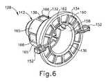
図4~図6に示されるように、静的結合部(128)は、長手方向軸に沿って遠位方向に狭まる一連の環状部分を有する静的本体(132)を含む。最大直径近位部分から最小直径遠位部分までの一連の環状部分は、より具体的には、近位フランジ(134)、電気ポッティング穴(136)、接続カラー(138)、外側ポスト(140)、及び内側ポスト(142)を含む。本実施例の静的本体(132)は、非導電性材料で一体的かつ単一的に形成され、これにより、電力が不注意に静的本体(132)の中を通過して、ワイヤ(126)によって供給される電力を短絡させることを阻止する。当然ながら、静的本体(132)は、既知の締結具及び/又は他の機械的に結合された構造体を使用して共に組み立てられた、様々な構成要素から代替的に形成されてもよいことが理解されよう。 As shown in FIGS. 4-6, the static junction (128) includes a static body (132) having a series of annular portions that narrow distally along the longitudinal axis. The series of annular portions from the proximal maximum diameter to the distal minimum diameter more specifically include the proximal flange (134), the electrical potting hole (136), the connecting collar (138), and the outer post (140). , And the inner post (142). The static body (132) of this embodiment is integrally and unitarily formed of a non-conductive material, whereby power is inadvertently passed through the static body (132) and the wire ( It prevents the power supplied by 126) from being short-circuited. Of course, the static body (132) may be formed alternative from various components assembled together using known fasteners and / or other mechanically coupled structures. Will be understood.
静的本体(132)は、非導電性であるが、静的結合部(128)は、本明細書において外側及び内側ケーブル接点(144、146)とも称される、導電性接点を更に含む。以下に更に詳細に記載される外側及び内側ケーブル接点(144、146)は、それぞれ、外側及び内側端子(148、150)を画定するように、外側及び内側ポスト(140、142)にそれぞれ固定される。本実施例の外側及び内側端子(148、150)は、正及び負のワイヤ(126)に電気的に接続するように構成された、正極及び負極端子(148、150)に対応する。当然ながら、他の実施例では、ケーブル(33)からトランスデューサアセンブリ(30)に電力を適切に結合することが所望される際、これら端子(148、150)の極性を反転させるための代替的な配線を使用することができる。 Although the static body (132) is non-conductive, the static coupling (128) further includes conductive contacts, also referred to herein as outer and inner cable contacts (144, 146). The outer and inner cable contacts (144, 146) described in more detail below are fixed to the outer and inner posts (140, 142), respectively, to define the outer and inner terminals (148, 150), respectively. To. The outer and inner terminals (148, 150) of this embodiment correspond to positive and negative terminal (148, 150) configured to be electrically connected to the positive and negative wires (126). Of course, in other embodiments, alternatives for reversing the polarities of these terminals (148, 150) when it is desired to properly couple power from the cable (33) to the transducer assembly (30). Wiring can be used.
静的本体(132)は、近位フランジ(134)がトランスデューサハウジング(114)に当接して更なる挿入を制限するまで、近位空洞(118)にトランスデューサハウジング(114)の近位開口部(122)を通して遠位に挿入されるように構成されている。近位フランジ(134)はまた、本体(18)と係合して、本体(18)に対する静的本体(132)の回転を阻止するように構成された一対の対向するタブ(152)を含む。各ハウジング(56)は、長手方向スロット(156)をそれらの間に画定する一対の長手方向に延在する内側リブ(154)を含む。各長手方向スロット(156)は、近位フランジ(134)から延在するそれぞれのタブ(152)を受容し、そのため静的本体(132)は、長手方向スロット(156)内への挿入及び/又は取り外しのために長手方向に摺動することができ、一方、リブ(154)は、タブ(152)と回転可能に係合し、それによってハウジング(56)に対する静的本体(132)の回転を阻止する。 The static body (132) has a proximal opening (114) in the transducer housing (114) in the proximal cavity (118) until the proximal flange (134) abuts on the transducer housing (114) to limit further insertion. It is configured to be inserted distally through 122). The proximal flange (134) also includes a pair of opposing tabs (152) configured to engage the body (18) and prevent rotation of the static body (132) with respect to the body (18). .. Each housing (56) includes a pair of longitudinally extending inner ribs (154) that define longitudinal slots (156) between them. Each longitudinal slot (156) accepts a tab (152) extending from the proximal flange (134) so that the static body (132) is inserted into and / or inserted into the longitudinal slot (156). Or can be slid longitudinally for removal, while the rib (154) rotatably engages the tab (152), thereby rotating the static body (132) relative to the housing (56). To prevent.
図4~図6に示されるように、電気ポッティング穴(136)は、近位フランジ(134)から遠位に延在し、外側及び内側ケーブル接点(144、146)との電気的接続のためにワイヤ(126)を機械的に取り付ける内側ボア(158)を画定する。一対の接触基部(160)は、以下により詳細に記載されるように、内側ボア(158)の周りを電気ポッティング穴(136)内で長手方向に延在し、外側及び内側ケーブル接点(144、146)の近位接触部材(162)を受容するように構成されている。それによって、電気ポッティング穴(136)は、ワイヤ(126)を機械的に取り付けるための空間を提供し、近位の接触部材(162)に直接などの、電気ポッティング穴(136)内にワイヤ(126)を取り付けるための任意の既知の構造が、本発明に従って使用され得ることが理解されよう。 As shown in FIGS. 4-6, the electrical potting holes (136) extend distally from the proximal flange (134) for electrical connection with the outer and inner cable contacts (144, 146). Defines an inner bore (158) to which the wire (126) is mechanically attached to. The pair of contact bases (160) extend longitudinally within the electrical potting holes (136) around the inner bore (158) and the outer and inner cable contacts (144,) as described in more detail below. It is configured to receive the proximal contact member (162) of 146). Thereby, the electric potting hole (136) provides a space for mechanically attaching the wire (126) into the wire (136) into the electric potting hole (136), such as directly to the proximal contact member (162). It will be appreciated that any known structure for mounting 126) can be used in accordance with the present invention.
電気ポッティング穴(136)の外側表面は、破片及び/又は流体などの異物が環状運動用シール(163)を遠位に越えて、更に近位空洞(118)内に通過することを阻止するために環状運動用シール(163)を受容するように更に構成されている。トランスデューサハウジング(114)の近位端部は、近位開口部(122)を包囲し、長手方向軸に沿って同心円状に整列する、環状運動用シール(163)を受容するように構成された環状近位溝(164)を含む。環状運動用シール(163)は、それによって、電気ポッティング穴(136)の外側表面とトランスデューサハウジング(114)の内側表面との間に位置決めされる。加えて、環状運動用シール(163)は、トランスデューサ(112)に向かう異物の遠位への通過を依然として阻止しながら、トランスデューサハウジング(114)と静的結合部(128)との間の相対回転を提供するように構成される。以下に記載されるように、スリップ接合部(110)及びトランスデューサアセンブリ(30)の様々な部分に異物が入り込むことを阻止するために、追加のシールが、本明細書における本発明に従って使用され得る。当然ながら、代替的な実施例は、スリップ接合部(110)及びトランスデューサアセンブリ(30)が望ましい使用を考慮して動作可能である限り、より多くのシールを使用してもよく、又はシールを使用しなくてもよい。このため、本発明は、本明細書に記載されているシール配置構成に不必要に制限されることを意図しない。 The outer surface of the electric potting hole (136) is to prevent foreign matter such as debris and / or fluid from passing distally beyond the annular motion seal (163) and further into the proximal cavity (118). Is further configured to receive the annular motion seal (163). The proximal end of the transducer housing (114) was configured to surround the proximal opening (122) and receive an annular motion seal (163) that is concentrically aligned along the longitudinal axis. Includes annular proximal groove (164). The annular motion seal (163) is thereby positioned between the outer surface of the electrical potting hole (136) and the inner surface of the transducer housing (114). In addition, the annular motion seal (163) rotates relative to the transducer housing (114) and the static junction (128) while still blocking the distal passage of foreign matter towards the transducer (112). Is configured to provide. As described below, additional seals may be used in accordance with the present invention to prevent foreign material from entering various parts of the slip junction (110) and the transducer assembly (30). .. Of course, alternative embodiments may use more seals, or use seals, as long as the slip joint (110) and transducer assembly (30) are operational in view of their desired use. You don't have to. For this reason, the invention is not intended to be unnecessarily restricted to the seal arrangement configurations described herein.
接続カラー(138)は、電気ポッティング穴(136)から遠位に延在し、複数の長手方向に延在する支持ガイド(165)及び複数の長手方向に延在するスナップ(166)を含む。支持ガイド(165)及びスナップ(166)は、接続カラー(138)の周りに角度の付いた状態で位置決めされ、一対の支持ガイド(165)の間の1つのスナップ(166)と交互に配置され、逆もまた同様である。例示的な接続カラー(138)は、4つの支持ガイド(165)及び4つのスナップ(166)を含む。各スナップ(166)は、電気ポッティング穴(136)から弾性的に延在し、内部環状リップ(168)を含むトランスデューサハウジング(114)への初期挿入時に、半径方向内向きに偏向するように構成されている。近位フランジ(134)が静的本体(132)の挿入中にトランスデューサハウジング(114)に近づくと、弾性スナップ(166)は内部環状リップ(168)を半径方向外向きに付勢し、内部環状リップ(168)と係合して、トランスデューサハウジング(114)に対する静的本体(132)の近位並進を制限する。このように、スナップ(166)及び静的結合部(128)の近位フランジ(134)は、それぞれ、トランスデューサハウジング(114)の内部環状リップ(168)及び近位端部と協働して、静的結合部(128)をトランスデューサハウジング(114)に長手方向に固着する。本実施例は、トランスデューサハウジング(114)を長手方向に係合するためのスナップ(166)を含むが、そのような固定に代替的な締結具を使用することができ、本明細書に記載される本発明は、必ずしもスナップ(166)に限定されることを意図するものではないことが理解されよう。 The connecting collar (138) includes a plurality of longitudinally extending support guides (165) and a plurality of longitudinally extending snaps (166) extending distally from the electrical potting hole (136). The support guides (165) and snaps (166) are positioned at an angle around the connection collar (138) and alternate with one snap (166) between the pair of support guides (165). , And vice versa. An exemplary connection collar (138) includes four support guides (165) and four snaps (166). Each snap (166) elastically extends from the electrical potting hole (136) and is configured to deflect radially inward upon initial insertion into the transducer housing (114) including the internal annular lip (168). Has been done. As the proximal flange (134) approaches the transducer housing (114) during insertion of the static body (132), the elastic snap (166) urges the internal annular lip (168) radially outward and the internal annular. Engage with the lip (168) to limit the proximal translation of the static body (132) to the transducer housing (114). Thus, the snap (166) and the proximal flange (134) of the static junction (128) cooperate with the internal annular lip (168) and the proximal end of the transducer housing (114), respectively. The static joint (128) is longitudinally secured to the transducer housing (114). The present embodiment includes snaps (166) for longitudinally engaging the transducer housing (114), although alternative fasteners can be used for such fixation and are described herein. It will be appreciated that the present invention is not necessarily intended to be limited to snaps (166).
静的結合部(128)は、トランスデューサハウジング(114)に対して長手方向に固着されるが、トランスデューサハウジング(114)及び静的結合部(128)は、相対回転するように構成されたままである。より具体的には、スナップ(166)は、長手方向の移動を制限するために内部環状リップ(168)と長手方向に重なり合うが、スナップ(116)は、トランスデューサハウジング(114)との回転係合をほとんど又は全く提供しない。接続カラー(138)とトランスデューサハウジング(114)との間にある程度の摩擦係合がある場合であっても、トランスデューサハウジング(114)は、静止結合部(128)に対して回転するように依然として構成される。いくつかの実施例では、スリップ接合部(110)は、使用中の摩擦を低減するために、相互間の相対回転を生じやすい1つ又は2つ以上の表面上に様々なコーティングを更に含んでもよい。いずれの場合も、トランスデューサハウジング(114)は、概して、接続カラー(138)上で所望どおりに自由に回転するように構成される。 The static coupling (128) is longitudinally secured to the transducer housing (114), while the transducer housing (114) and static coupling (128) remain configured to rotate relative to each other. .. More specifically, the snap (166) longitudinally overlaps the internal annular lip (168) to limit longitudinal movement, whereas the snap (116) is rotationally engaged with the transducer housing (114). With little or no provision. Even if there is some frictional engagement between the connection collar (138) and the transducer housing (114), the transducer housing (114) is still configured to rotate with respect to the quiescent coupling (128). Will be done. In some embodiments, the slip junction (110) may further comprise various coatings on one or more surfaces that are prone to relative rotation between each other in order to reduce friction during use. good. In each case, the transducer housing (114) is generally configured to rotate freely as desired on the connecting collar (138).
外側ポスト(140)は、支持ガイド(165)から半径方向内向きに接続カラー(138)に堅く接続され、接続カラー(138)から遠位に延在する。同様に、内側ポストは、内側ポストから半径方向内向きに外側ポスト(140)に堅く接続され、動的結合部(130)に向かって遠位に延在する。各外側及び内側ポスト(140、142)は、それぞれの遠位環状表面(図示せず)を有する略円筒形である。遠位環状表面(図示せず)の各々は、図5~図7に示されるように、外側及び内側ケーブル接点(144、146)をそれぞれ受容する。より具体的には、外側及び内側ケーブル接点(144、146)は、静的結合部(128)に対する動的結合部(130)の回転位置に関係なく電気的接続を提供するための、遠位環状表面(図示せず)を囲むそれぞれの遠位環状リング(174)を有する。近位接触部材(162)は、上述のように、ワイヤ(126)と接続するために、遠位環状リング(174)から電気ポッティング穴(136)内に近位に延在する。加えて、複数のアンカー部材(176)がまた、遠位環状リング(174)から近位に延在しており、外側及び内側ケーブル接点(144、146)を外側及び内側ポスト(140、142)に固定して、外側及び内側端子(148、150)を形成するように構成されている。一実施例において、遠位環状リング(174)、アンカー部材(176)、及び近位接触部材(162)は、導電性材料から単一的かつ一体的に形成され、追加の導電性のために金めっきされてもよい。しかしながら、外側及び内側ケーブル接点(144、146)を形成するための様々な構成要素の代替的な構成もまた、他の実施例で使用され得ることが理解されよう。このため、本明細書に記載される本発明は、本実施例に示される単一的かつ一体的に形成された外側及び内側ケーブル接点(144、146)に不必要に限定されることを意図するものではない。 The outer post (140) is tightly connected radially inward from the support guide (165) to the connecting collar (138) and extends distally from the connecting collar (138). Similarly, the inner post is tightly connected radially inward from the inner post to the outer post (140) and extends distally towards the dynamic junction (130). Each outer and inner post (140, 142) is substantially cylindrical with a respective distal annular surface (not shown). Each of the distal annular surfaces (not shown) receives the outer and inner cable contacts (144, 146), respectively, as shown in FIGS. 5-7. More specifically, the outer and inner cable contacts (144, 146) are distal to provide electrical connection to the static coupling (128) regardless of the rotational position of the dynamic coupling (130). Each has a distal annular ring (174) surrounding an annular surface (not shown). The proximal contact member (162) extends proximally into the electrical potting hole (136) from the distal annular ring (174) to connect with the wire (126), as described above. In addition, a plurality of anchor members (176) also extend proximally from the distal annular ring (174), with outer and inner cable contacts (144, 146) on the outer and inner posts (140, 142). It is configured to form outer and inner terminals (148, 150) by being fixed to. In one embodiment, the distal annular ring (174), anchor member (176), and proximal contact member (162) are formed from the conductive material in a single and integral manner for additional conductivity. It may be gold-plated. However, it will be appreciated that alternative configurations of various components for forming the outer and inner cable contacts (144, 146) can also be used in other embodiments. For this reason, the invention described herein is intended to be unnecessarily limited to the single and integrally formed outer and inner cable contacts (144, 146) set forth in this example. It's not something to do.
図4及び図8~図11は、第1の例示的な動的結合部(130)をより詳細に示す。この目的のために、動的結合部(130)は、略円筒形を有する動的本体(178)を含む。動的本体(178)は、静的結合部(128)を受容するように構成された近位面(180)と、トランスデューサ(112)に当接するように構成された遠位面(182)と、トランスデューサハウジング(114)内に固定するように構成された外側環状表面(186)とを含む。本実施例の外側環状表面(186)は、遠位空洞(120)を囲む複数の内側ねじ山(190)と螺着可能に係合する複数の外側ねじ山(188)を含む。遠位空洞(120)内に設置されている間、動的結合部(130)は、動的本体(178)の近位面(180)がトランスデューサハウジング(114)の遠位空洞(120)内の座部(192)と係合するまで、回転可能に近位に駆動される。本実施例の遠位面(182)は、設置中の更なる工具グリップのための線状スロット(194)を更に含む。加えて、静的シール(195)は、一対の外側環状フランジ(197)の間の環状溝(196)内の外側環状表面(186)の一部分を取り囲む。このため、動的本体(178)の内側表面は、トランスデューサ(112)を更に封止し、かつ運動用シール(163)を通過した可能性がある異物が静的シール(195)を越えて遠位に通過するのを阻止するために、静的シール(195)に対して圧縮される(図4参照)。 4 and 8-11 show the first exemplary dynamic coupling (130) in more detail. For this purpose, the dynamic coupling portion (130) includes a dynamic body (178) having a substantially cylindrical shape. The dynamic body (178) has a proximal surface (180) configured to receive the static coupling (128) and a distal surface (182) configured to abut the transducer (112). , Includes an outer annular surface (186) configured to be secured within the transducer housing (114). The outer annular surface (186) of this embodiment includes a plurality of outer threads (188) that are screwably engaged with a plurality of inner threads (190) surrounding the distal cavity (120). While installed in the distal cavity (120), the dynamic junction (130) has the proximal surface (180) of the dynamic body (178) in the distal cavity (120) of the transducer housing (114). It is rotatably and proximally driven until it engages with the seat (192) of the. The distal surface (182) of this embodiment further includes a linear slot (194) for additional tool grips during installation. In addition, the static seal (195) surrounds a portion of the outer annular surface (186) within the annular groove (196) between the pair of outer annular flanges (197). For this reason, the inner surface of the dynamic body (178) further seals the transducer (112) and foreign matter that may have passed through the exercise seal (163) is far beyond the static seal (195). Compressed against the static seal (195) to prevent it from passing through the position (see Figure 4).
動的アセンブリ(178)は、外側ボア(198)と、内側ボア(200)とを更に含む。外側ボア(198)は、内側ボア(200)よりも大きい直径を有するが、概して、内側ボア(200)よりも浅い。外側及び内側ボア(198、200)は、長手方向軸に沿って同心円状に整列され、静的結合部(128)の外側及び内側端子(148、150)をそれぞれ受容するように位置決めされる。加えて、外側及び内側ボア(198、200)は、内部に取り付けられたそれぞれの環状トランスデューサ接点(204a、204b)を有する。各トランスデューサ接点(204a、204b)は、外側及び内側ボア(198、200)の周りに角度を付けて位置決めされた、複数の弾性で内向きに延在する接触アーム(206)を含む。接触アーム(206)は、外側及び内側ケーブル接点(144、146)との電気通信のために、静的結合部(128)の外側及び内側ケーブル接点(144、146)に向かって延在し、かつこれらと接触する。例示的なトランスデューサ接点(204a、204b)は、各々、外側及び内側ボア(198、200)の周りに等角に位置決めされた4つの接触アーム(206)を有するが、外側及び内側ケーブル接点(144、146)との電気通信を維持するために、代替的な数及びトランスデューサ接点(204a、204b)に対する位置決めが、所望どおりに設置され得ることが理解されよう。 The dynamic assembly (178) further includes an outer bore (198) and an inner bore (200). The outer bore (198) has a larger diameter than the inner bore (200), but is generally shallower than the inner bore (200). The outer and inner bores (198, 200) are concentrically aligned along the longitudinal axis and positioned to receive the outer and inner terminals (148, 150) of the static coupling (128), respectively. In addition, the outer and inner bores (198,200) have their respective annular transducer contacts (204a, 204b) mounted inside. Each transducer contact (204a, 204b) includes a plurality of elastic, inwardly extending contact arms (206) that are angled around the outer and inner bores (198, 200). The contact arm (206) extends towards the outer and inner cable contacts (144, 146) of the static coupling (128) for telecommunications with the outer and inner cable contacts (144, 146). And come into contact with these. An exemplary transducer contact (204a, 204b) has four contact arms (206) equiangularly positioned around the outer and inner bores (198, 200), respectively, while the outer and inner cable contacts (144). It will be appreciated that in order to maintain telecommunications with 146), alternative numbers and positioning with respect to the transducer contacts (204a, 204b) can be installed as desired.
各トランスデューサ接点(204a、204b)は、近位面(180)を通って遠位面(182)まで遠位に延在する、遠位接触部材(208)を更に含む。具体的には、各遠位接触部材(208)は、遠位面(182)上の遠位ポッティング穴(210)内で遠位に終端する。各遠位ポッティング穴(210)は、トランスデューサ(112)を、例えば追加のワイヤ(212)によって、トランスデューサ接点(204a、204b)に電気的に接続するのに十分な空間を提供するように構成されている。各トランスデューサ接点(204a、204b)はまた、一対の対向するアンカー部材(214)を有して、各々のトランスデューサ接点(204a、204b)を、それぞれ、各外側及び内側ボア(198、200)内に堅く固定する。 Each transducer contact (204a, 204b) further comprises a distal contact member (208) extending distally through the proximal plane (180) to the distal plane (182). Specifically, each distal contact member (208) terminates distally within a distal potting hole (210) on the distal surface (182). Each distal potting hole (210) is configured to provide sufficient space to electrically connect the transducer (112) to the transducer contacts (204a, 204b), eg, by additional wire (212). ing. Each transducer contact (204a, 204b) also has a pair of opposing anchor members (214) with each transducer contact (204a, 204b) in each outer and inner bore (198, 200), respectively. Securely fix.
本実施例に関して本明細書に示され、かつ記載されるように、トランスデューサ接点(204a、204b)は、長手方向軸を横断する平面において長手方向軸の周りで外側プロファイルを画定し、外側及び内側ケーブル接点(144、146)の各々は、それぞれ、長手方向軸を横断する平面内で長手方向軸の周りで外側プロファイルを画定する。各トランスデューサ接点(204a、204b)並びに外側及び内側ケーブル接点(144、146)の外側プロファイルは、圧電素子(36)並びにトランスデューサハウジング(114)を有するトランスデューサ(34)の外側プロファイルよりも小さい。加えて、外側及び内側ケーブル接点(144、146)はまた、トランスデューサ接点(204a、204b)のそれぞれの外側プロファイルよりも小さい。したがって、外側及び内側ケーブル接点(144、146)並びにトランスデューサ接点(204a、204b)の外側プロファイルは、トランスデューサアセンブリ(30)及びスリップ接合部(110)のサイズを低減するために、トランスデューサ(34)及びトランスデューサハウジング(114)の外側プロファイル内に全て入れ子にされる。このため、トランスデューサアセンブリ(30)及びスリップ接合部(110)を収容するための本体(18)の全体的なサイズは、ユーザによってより容易に操作され得る、より小さく、より簡便な収容のために、トランスデューサアセンブリ(30)を取り囲む代替的なスリップ接合部と比較して、長手方向軸の周りで低減される。 As shown and described herein with respect to this embodiment, the transducer contacts (204a, 204b) define an outer profile around the longitudinal axis in a plane across the longitudinal axis, outer and inner. Each of the cable contacts (144, 146) defines an outer profile around the longitudinal axis in a plane traversing the longitudinal axis, respectively. The outer profile of each transducer contact (204a, 204b) and the outer and inner cable contacts (144, 146) is smaller than the outer profile of the transducer (34) having the piezoelectric element (36) and the transducer housing (114). In addition, the outer and inner cable contacts (144, 146) are also smaller than the respective outer profiles of the transducer contacts (204a, 204b). Therefore, the outer profiles of the outer and inner cable contacts (144, 146) and the transducer contacts (204a, 204b) have the transducer (34) and the transducer (34) to reduce the size of the transducer assembly (30) and slip junction (110). All nested within the outer profile of the transducer housing (114). For this reason, the overall size of the body (18) for accommodating the transducer assembly (30) and slip junction (110) is for smaller and more convenient accommodation that can be more easily manipulated by the user. , Reduced around the longitudinal axis compared to alternative slip junctions surrounding the transducer assembly (30).
使用中、図3~図11は、スリップ接合部(110)を介してケーブル(33)と機械的かつ電気的に結合されたトランスデューサアセンブリ(30)を示す。外科用器具(10)の操作及び患者の治療中、ユーザは、エンドエフェクタ(16)をシャフトアセンブリ(14)の長手方向軸の周りで所望の角度配向で位置決めするために、ノブ(54)を選択的に回転させる。そうすることで、ユーザはまた、シャフトアセンブリ(14)、導波管(38)、及びトランスデューサアセンブリ(30)を、シャフトアセンブリ(14)の長手方向軸の周りで集合的に回転させる。トランスデューサ(112)と電気的かつ機械的に結合された動的結合部(130)もまた、トランスデューサアセンブリ(30)と共に回転し、一方、静的結合部(128)は器具本体(18)に対して回転して固着されたままである。より具体的には、内部リブ(154)は、タブ(152)と係合して、近位開口部(122)を通ってトランスデューサハウジング(114)の遠位部分(116)内に長手方向に固着されながら、静的結合部(128)の回転を阻止する。 In use, FIGS. 3-11 show a transducer assembly (30) mechanically and electrically coupled to a cable (33) via a slip junction (110). During the operation of the surgical instrument (10) and the treatment of the patient, the user sets the knob (54) to position the end effector (16) in the desired angular orientation around the longitudinal axis of the shaft assembly (14). Selectively rotate. In doing so, the user also collectively rotates the shaft assembly (14), waveguide (38), and transducer assembly (30) around the longitudinal axis of the shaft assembly (14). The dynamic coupling (130), which is electrically and mechanically coupled to the transducer (112), also rotates with the transducer assembly (30), while the static coupling (128) with respect to the instrument body (18). Rotates and remains fixed. More specifically, the internal rib (154) engages the tab (152) and longitudinally into the distal portion (116) of the transducer housing (114) through the proximal opening (122). While being fixed, it prevents the rotation of the static joint (128).
静的結合部(128)と動的結合部(130)との間の電気通信を維持するために、トランスデューサ接点(204a、204b)の接触アーム(206)は、接触アーム(206)が外側及び内側ケーブル接点(144、146)の周りを回転する際、外側及び内側ケーブル接点(144、146)に対して半径方向に付勢されたままである。このため、ユーザは、トランスデューサアセンブリ(30)を、長手方向軸の周りで任意の回転位置に移動させることができ、接触アーム(206)は、外側及び内側ケーブル接点(144、146)と物理的に接触したままとなり、トランスデューサ(112)とケーブル(33)との間の電気通信を維持する。 In order to maintain telecommunications between the static coupling (128) and the dynamic coupling (130), the contact arm (206) of the transducer contacts (204a, 204b) has the contact arm (206) on the outside and the contact arm (206) on the outside. As it rotates around the inner cable contacts (144, 146), it remains radially urged with respect to the outer and inner cable contacts (144, 146). This allows the user to move the transducer assembly (30) to any rotational position around the longitudinal axis, with the contact arm (206) physically with the outer and inner cable contacts (144, 146). Remains in contact with and maintains telecommunications between the transducer (112) and the cable (33).
動的結合部(130)が回転する間、静的結合部(128)は、器具本体(18)に対して静止したままである。このため、ワイヤ(126)が静的結合部(138)に接続されたケーブル(33)は、ケーブル(33)がトランスデューサアセンブリ(30)の回転中に巻き取られることを更に阻止するために、器具本体(18)に対して回転することを阻止される。 While the dynamic coupling (130) rotates, the static coupling (128) remains stationary with respect to the instrument body (18). Therefore, the cable (33) to which the wire (126) is connected to the static coupling (138) further prevents the cable (33) from being wound up during rotation of the transducer assembly (30). It is prevented from rotating with respect to the instrument body (18).
B.第2の例示的なスリップ接合部
図12~図15は、トランスデューサアセンブリ(30)と接続された第2の例示的なスリップ接合部(310)を示す。トランスデューサアセンブリ(30)は、トランスデューサハウジング(314)内に収容されたトランスデューサ(112)を有する。スリップ接合部(310)は、近位空洞(318)及び隣接する遠位空洞(320)を有するトランスデューサハウジング(314)の遠位部分(316)に一体化される。近位空洞(318)は、遠位空洞(320)と近位開口部(322)との間で、本体(18)内のトランスデューサハウジング(314)の外部まで延在する。本実施例では、スリップ接合部(310)は、長手方向軸に沿って遠位空洞(320)及び近位空洞(322)内に概して位置決めされる。より具体的には、スリップ接合部(310)、遠位空洞(320)、及び近位空洞(322)は、長手方向軸に沿って同心円状に整列され、遠位空洞(320)は、近位空洞(322)よりも大きい直径を有する。
B. Second Exemplary Slip Joint FIGS. 12-15 show a second exemplary slip joint (310) connected to the transducer assembly (30). The transducer assembly (30) has a transducer (112) housed within a transducer housing (314). The slip junction (310) is integrated into the distal portion (316) of the transducer housing (314) having a proximal cavity (318) and an adjacent distal cavity (320). The proximal cavity (318) extends between the distal cavity (320) and the proximal opening (322) to the outside of the transducer housing (314) within the body (18). In this embodiment, the slip junction (310) is generally positioned in the distal cavity (320) and the proximal cavity (322) along the longitudinal axis. More specifically, the slip junction (310), the distal cavity (320), and the proximal cavity (322) are concentrically aligned along the longitudinal axis, and the distal cavity (320) is near. It has a larger diameter than the cavity (322).
トランスデューサハウジング(314)は、長手方向軸を横断する平面において長手方向軸の周りで外側プロファイルを画定する。スリップ接合部(310)は、トランスデューサハウジング(314)の遠位部分(316)に一体化され、そのためスリップ接合部(310)は、トランスデューサハウジング(314)の外側プロファイル内に嵌合するように横方向にサイズ決めされる。本実施例では、スリップ結合部(310)の横断面における外側プロファイルは、長手方向軸の周りのトランスデューサハウジング(314)の外側プロファイルよりも小さい。加えて、圧電素子(36)を有するトランスデューサ(34)はまた、トランスデューサハウジング(314)の外側プロファイルよりも小さい横断面内の外側プロファイルを画定する。更なる実施例として、圧電素子(36)を有するトランスデューサ(34)の外側プロファイルは、スリップ接合部(310)の外側プロファイルよりも大きい。 The transducer housing (314) defines an outer profile around the longitudinal axis in a plane traversing the longitudinal axis. The slip junction (310) is integrated into the distal portion (316) of the transducer housing (314) so that the slip junction (310) is laterally fitted within the outer profile of the transducer housing (314). Sized in the direction. In this embodiment, the outer profile in the cross section of the slip joint (310) is smaller than the outer profile of the transducer housing (314) around the longitudinal axis. In addition, the transducer (34) with the piezoelectric element (36) also defines an outer profile within the cross section that is smaller than the outer profile of the transducer housing (314). As a further embodiment, the outer profile of the transducer (34) with the piezoelectric element (36) is larger than the outer profile of the slip junction (310).
スリップ接合部(110)(図4を参照)と同様に、スリップ接合部(310)はまた、近位空洞(318)内に位置決めされた近位静的結合部(328)と、遠位空洞(320)内に位置決めされた遠位動的結合部(330)とを含む。静的結合部(328)は、正及び負のワイヤ(126)から電力を受容し、トランスデューサアセンブリ(30)に給電するために動的結合部(330)に電力を方向付ける。トランスデューサハウジング(314)は、次に、静的結合部(328)と動的結合部(330)との間の相対運動を提供しながら、それらの間に電力を伝達するために、静的及び動的結合部(328、330)を互いに対して機械的に支持する。 Similar to the slip junction (110) (see FIG. 4), the slip junction (310) also has a proximal static junction (328) positioned within the proximal cavity (318) and a distal cavity. Includes a distal dynamic junction (330) positioned within (320). The static coupling (328) receives power from the positive and negative wires (126) and directs power to the dynamic coupling (330) to power the transducer assembly (30). The transducer housing (314) is then statically and statically and to transfer power between the static couplings (328) and the dynamic couplings (330) while providing relative motion between them. Dynamic couplings (328, 330) are mechanically supported against each other.
図12~図14に示されるように、静的結合部(328)は、長手方向軸に沿って近位方向に狭まる一連の環状部分を有する静的本体(332)を含む。最小直径近位部分から最大直径遠位部分までの一連の環状部分は、より具体的には、電気ポッティング穴(336)、円筒形首部(338)、及び遠位円筒形壁(340)を含む。本実施例の静的本体(332)は、電気的非導電性材料で一体的かつ単一的に形成され、これにより、電力が不注意に静的本体(332)を通過して、ワイヤ(126)によって供給される電力を短絡させることを阻止する。当然ながら、静的本体(332)は、既知の締結具及び/又は他の機械的に結合された構造体を使用して共に組み立てられた、様々な構成要素から代替的に形成されてもよいことが理解されよう。 As shown in FIGS. 12-14, the static junction (328) includes a static body (332) having a series of annular portions that narrow proximally along the longitudinal axis. The series of annular portions from the minimum diameter proximal portion to the maximum diameter distal portion more specifically includes an electrical potting hole (336), a cylindrical neck (338), and a distal cylindrical wall (340). .. The static body (332) of this embodiment is integrally and unitarily formed of an electrically non-conductive material, whereby power is inadvertently passed through the static body (332) and the wire (332). It prevents the power supplied by 126) from being short-circuited. Of course, the static body (332) may be formed alternative from various components assembled together using known fasteners and / or other mechanically coupled structures. Will be understood.
静的本体(332)は、非導電性であるが、静的結合部(128)は、外側及び内側ケーブル接点(344、346)を更に含む。以下で更に詳細に記載される外側及び内側ケーブル接点(344、346)は、それぞれ外側及び内側端子(348、350)を画定するために、遠位面(343)上の外側及び内側環状溝(341、342)内にそれぞれ固定される。本実施例の外側及び内側端子(348、350)は、正及び負のワイヤ(126)に電気的に接続するように構成された、正極端子及び負極端子(348、350)に対応する。当然ながら、他の実施例では、ケーブル(34)からトランスデューサアセンブリ(30)に電力を適切に結合することが所望される際、これらの端子(348、350)の極性を反転させるための代替的な配線を使用することができる。 The static body (332) is non-conductive, while the static coupling (128) further includes outer and inner cable contacts (344, 346). The outer and inner cable contacts (344, 346), described in more detail below, are outer and inner annular grooves (344, 346) on the distal surface (343) to define the outer and inner terminals (348, 350), respectively. It is fixed in 341 and 342), respectively. The outer and inner terminals (348, 350) of this embodiment correspond to positive and negative terminal (348, 350) configured to be electrically connected to the positive and negative wires (126). Of course, in other embodiments, alternatives for reversing the polarities of these terminals (348, 350) when it is desired to properly couple power from the cable (34) to the transducer assembly (30). Wiring can be used.
静的本体(332)は、遠位円筒形壁(340)が遠位空洞(320)内のトランスデューサハウジング(314)に当接して更なる挿入を制限するまで、遠位及び近位空洞(320、318)によってトランスデューサハウジング(114)の近位開口部(122)を通って近位方向に挿入されるように構成されている。具体的には、電気ポッティング穴(336)は、近位開口部(322)を通って、トランスデューサハウジング(314)から近位に突出する。電気ポッティング穴(336)の外側表面は、本体(18)に対する蝶ナット(353)及び静的本体(332)の回転を阻止するために本体(18)と係合するように構成された一対の対向するタブ(353)を有する蝶ナット(353)などの締結具を螺着可能に受容するように構成された複数のねじ山(352)を含む。本体(18)は、間に横断スロット(356)を画定する一対の上部及び下部内部リブ(354)を含む。各横断スロット(356)は、蝶ナット(352)のそれぞれのタブ(353)を受容し、一方、リブ(354)は、タブ(353)と回転可能に係合し、それによって本体(18)に対する静的本体(332)の回転を阻止する。 The static body (332) is a distal and proximal cavity (320) until the distal cylindrical wall (340) abuts on the transducer housing (314) within the distal cavity (320) to limit further insertion. , 318) are configured to be inserted proximally through the proximal opening (122) of the transducer housing (114). Specifically, the electrical potting hole (336) projects proximally from the transducer housing (314) through the proximal opening (322). The outer surface of the electric potting hole (336) is a pair configured to engage the body (18) to prevent rotation of the wing nut (353) and the static body (332) with respect to the body (18). Includes a plurality of threads (352) configured to screwably receive fasteners such as wing nuts (353) with opposed tabs (353). The body (18) includes a pair of upper and lower internal ribs (354) defining a transverse slot (356) in between. Each crossing slot (356) receives a respective tab (353) of the wing nut (352), while the rib (354) rotatably engages the tab (353) thereby the body (18). Prevents the rotation of the static body (332) with respect to.
電気ポッティング穴(336)は、外側及び内側ケーブル接点(344、346)との電気的接続のためにワイヤ(126)をその内部に機械的に装着する内側ボア(358)を画定する。一対の接触チャネル(360)は、以下により詳細に記載されるように、首部(338)を通って遠位面(343)から、電気ポッティング穴(336)まで長手方向に延在し、外側及び内側ケーブル接点(344、346)の近位接触部材(362)を受容するように構成されている。これにより、電気ポッティング穴(336)は、ワイヤ(126)を機械的に取り付けるための空間を提供し、近位の接触部材(362)に直接などの、電気ポッティング穴(336)内にワイヤ(126)を取り付けるための任意の既知の構造が、本発明に従って使用され得ることが理解されよう。 The electrical potting holes (336) define an inner bore (358) into which a wire (126) is mechanically mounted for electrical connection with outer and inner cable contacts (344, 346). The pair of contact channels (360) extend longitudinally from the distal surface (343) through the neck (338) to the electrical potting holes (336), outward and outward, as described in more detail below. It is configured to receive the proximal contact member (362) of the inner cable contact (344, 346). Thereby, the electric potting hole (336) provides a space for mechanically attaching the wire (126) into the wire (336) into the electric potting hole (336), such as directly to the proximal contact member (362). It will be appreciated that any known structure for mounting 126) can be used in accordance with the present invention.
首部(338)は、近位空洞(318)を通して電気ポッティング穴(36)と遠位円筒形壁(340)との間を剛性に接続するために、電気ポッティング穴(36)から遠位円筒形壁(340)まで遠位に延在する。首部(338)は、破片及び/又は流体などの異物が環状運動用シール(363)を遠位に越えて、更に近位空洞(318)内に通過することを阻止するために、環状運動用シール(363)を受容するように更に構成されている。首部(338)は、トランスデューサハウジング(314)の内側表面に対して近位空洞(318)を取り囲む環状運動用シール(363)を受容するように構成された環状近位溝(364)を含む。本実施例では、環状運動用シール(363)は、首部(338)の外側表面とトランスデューサハウジング(314)の内側表面との間に位置決めされた長手方向軸に沿って同心円状に整列される。加えて、環状運動用シール(363)は、トランスデューサ(112)に向かう異物流体の遠位への通過を依然として阻止しながら、トランスデューサハウジング(314)と静的結合部(328)との間の相対回転を提供するように構成される。 The neck (338) is distally cylindrical from the electrical potting hole (36) to provide a rigid connection between the electrical potting hole (36) and the distal cylindrical wall (340) through the proximal cavity (318). It extends distally to the wall (340). The neck (338) is for annular movement to prevent foreign matter such as debris and / or fluid from passing distally beyond the annular movement seal (363) and further into the proximal cavity (318). It is further configured to accept the seal (363). The neck (338) includes an annular proximal groove (364) configured to receive an annular motion seal (363) surrounding the proximal cavity (318) with respect to the inner surface of the transducer housing (314). In this embodiment, the annular motion seal (363) is concentrically aligned along a longitudinal axis positioned between the outer surface of the neck (338) and the inner surface of the transducer housing (314). In addition, the annular motion seal (363) is relative between the transducer housing (314) and the static junction (328) while still blocking the distal passage of foreign fluid towards the transducer (112). It is configured to provide rotation.
近位空洞(320)に隣接して遠位に位置決めされた遠位円筒形壁(340)と、近位空洞(320)に隣接して近位に位置決めされた蝶ナット(352)と、それらの間に延在する首部(338)とにより、静的結合部(328)は、トランスデューサハウジング(314)に対して長手方向に固着されるが、依然として相対的に回転するように構成されている。相対回転を補助するために、静的結合部(328)とトランスデューサハウジング(314)との間に摩擦を発生させる傾向がある係合表面は、シリコンなどの低摩擦コーティングでコーティングされてもよい。依然として、静的結合部(328)とトランスデューサハウジング(314)との間にある程度の摩擦係合がある場合であっても、トランスデューサハウジング(314)は、静止結合部(328)に対して回転するように依然として構成される。 A distal cylindrical wall (340) positioned distally adjacent to the proximal cavity (320) and a wing nut (352) positioned proximally adjacent to the proximal cavity (320) and them. With the neck (338) extending in between, the static joint (328) is longitudinally anchored to the transducer housing (314) but is still configured to rotate relative to it. .. To aid relative rotation, the engaging surface, which tends to generate friction between the static coupling (328) and the transducer housing (314), may be coated with a low friction coating such as silicon. The transducer housing (314) still rotates with respect to the static coupling (328), even if there is some frictional engagement between the static coupling (328) and the transducer housing (314). Is still configured.
遠位円筒形壁(340)は、首部(338)から、外側端子及び内側端子(348、350)を含む遠位面(343)まで遠位に延在する。より具体的には、外側及び内側ケーブル接点(344、346)は、上述のように、ワイヤ(126)との接続のために、電気ポッティング穴(336)内に近位に延在する近位接触部材(362)を有する外側及び内側環状リング(370、372)をそれぞれ含む。本実施例では、外側環状リング(370)は、内側環状リング(372)よりも大きい直径を有し、内側環状リング(372)は、外側環状リング(370)内で同心円状に位置決めされる。加えて、複数のアンカー部材(376)がまた、外側及び内側環状リング(370、372)から近位に延在しており、外側及び内側ケーブル接点(344、346)の遠位面(343)を外側及び内側環状溝(341、342)内に固定して、外側及び内側端子(348、350)を形成するように構成されている。いくつかの変形形態では、外側及び内側ケーブル接点(344、346)の各々は、導電性材料から単一的かつ一体的に形成され、追加の導電性のために金めっきされてもよい。しかしながら、外側及び内側ケーブル接点(344、346)を形成するための様々な構成要素の代替的な構成もまた、他の実施例で使用され得ることが理解されよう。このため、本明細書に記載される本発明は、本実施例に示される単一的かつ一体的に形成された外側及び内側ケーブル接点(344、346)に不必要に限定されることを意図するものではない。 The distal cylindrical wall (340) extends distally from the neck (338) to the distal surface (343) including the outer and inner terminals (348, 350). More specifically, the outer and inner cable contacts (344, 346) are proximally extending within the electrical potting hole (336) for connection with the wire (126), as described above. Includes outer and inner annular rings (370, 372) with contact members (362), respectively. In this embodiment, the outer annular ring (370) has a larger diameter than the inner annular ring (372) and the inner annular ring (372) is concentrically positioned within the outer annular ring (370). In addition, a plurality of anchor members (376) also extend proximally from the outer and inner annular rings (370, 372) and the distal faces (343) of the outer and inner cable contacts (344, 346). Is configured to be fixed in the outer and inner annular grooves (341, 342) to form the outer and inner terminals (348, 350). In some variants, each of the outer and inner cable contacts (344, 346) may be single and integrally formed from the conductive material and gold plated for additional conductivity. However, it will be appreciated that alternative configurations of various components for forming the outer and inner cable contacts (344, 346) can also be used in other embodiments. For this reason, the invention described herein is intended to be unnecessarily limited to the single and integrally formed outer and inner cable contacts (344, 346) set forth in this example. It's not something to do.
図12、図13、及び図15は、第1の例示的な動的結合部(330)をより詳細に示す。この目的のために、動的結合部(330)は、略円筒形を有する動的本体(378)を含む。動的本体(378)は、静的結合部(328)を受容するように構成された近位面(380)と、トランスデューサ(112)に当接するように構成された遠位面(382)と、トランスデューサハウジング(314)内に固定するように構成された外側環状表面(386)とを含む。本実施例の外側環状表面(386)は、遠位空洞(320)を囲む複数の内側ねじ山(390)と螺着可能に係合する複数の外側ねじ山(388)を含む。遠位空洞(320)内に設置されている間、動的結合部(330)は、動的本体(378)の近位面(380)がトランスデューサハウジング(314)の遠位空洞(320)内の座部(392)と係合するまで、回転可能に近位に駆動される。本実施例の遠位面(182)は、設置中の工具グリップのための、六角凹部などの機械的に係合可能な凹部(394)を更に含む。 12, 13, and 15 show the first exemplary dynamic coupling (330) in more detail. For this purpose, the dynamic coupling (330) includes a dynamic body (378) having a substantially cylindrical shape. The dynamic body (378) has a proximal surface (380) configured to receive the static junction (328) and a distal surface (382) configured to abut the transducer (112). , Includes an outer annular surface (386) configured to be secured within the transducer housing (314). The outer annular surface (386) of this embodiment includes a plurality of outer threads (388) that are screwably engaged with a plurality of inner threads (390) surrounding the distal cavity (320). While installed in the distal cavity (320), the dynamic coupling (330) has the proximal surface (380) of the dynamic body (378) in the distal cavity (320) of the transducer housing (314). It is rotatably and proximally driven until it engages with the seat (392) of the. The distal surface (182) of this embodiment further includes a mechanically engageable recess (394), such as a hexagonal recess, for a tool grip during installation.
動的本体(178)は、内側ボア(400)から半径方向外向きに位置決めされた外側ボア(398)を更に含む。外側ボア(398)は、長手方向軸の周りで外側ケーブル接点(344)と半径方向に整列し、一方で内側ボア(400)は、長手方向軸の周りで内側ケーブル接点(346)と半径方向に整列する。各外側及び内側ボア(398、400)は、複数弾性でかつ近位に延在する接触アーム(406)を有するトランスデューサ接点(404)を受容する。これにより、接触アーム(406)は、近位に延在し、静的結合部(328)の外側及び内側ケーブル接点(344、346)と、相互間の電気通信のために接触するように位置決めされる。 The dynamic body (178) further includes an outer bore (398) positioned radially outward from the inner bore (400). The outer bore (398) is radially aligned with the outer cable contact (344) around the longitudinal axis, while the inner bore (400) is radially aligned with the inner cable contact (346) around the longitudinal axis. Align to. Each outer and inner bore (398, 400) receives a transducer contact (404) with multiple elastic and proximally extending contact arms (406). Thereby, the contact arm (406) extends proximally and is positioned to contact the outer and inner cable contacts (344, 346) of the static coupling (328) for telecommunications between each other. Will be done.
各トランスデューサ接点(404)は、アーム(406)から近位面(380)から遠位面(382)まで遠位に延在する、遠位接触部材(408)を更に含む。具体的には、各遠位接触部材(308)は、遠位面(482)上の遠位ポッティング穴(410)内で遠位に終端する。各遠位ポッティング穴(410)は、トランスデューサ(412)を、例えば追加のワイヤ(412)によって、トランスデューサ接点(404)に電気的に接続するのに十分な空間を提供するように構成されている。各トランスデューサ接点(404)はまた、一対の対向するアンカー部材(図示せず)を有して、各トランスデューサ接点(404)を、トランスデューサ接点(404)それぞれの外側及び内側ボア(398、400)内に堅く固定する。 Each transducer contact (404) further comprises a distal contact member (408) extending distally from the arm (406) to the proximal plane (380) to the distal plane (382). Specifically, each distal contact member (308) terminates distally within a distal potting hole (410) on the distal surface (482). Each distal potting hole (410) is configured to provide sufficient space to electrically connect the transducer (412) to the transducer contact (404), for example with an additional wire (412). .. Each transducer contact (404) also has a pair of opposing anchor members (not shown) with each transducer contact (404) in the outer and inner bores (398, 400) of the transducer contact (404), respectively. Firmly fixed to.
本実施例に関して本明細書に示され、かつ記載されるように、トランスデューサ接点(404)は、長手方向軸を横断する平面において長手方向軸の周りで外側プロファイルを画定し、外側及び内側ケーブル接点(344、346)の各々は、それぞれ、長手方向軸を横断する平面内で長手方向軸の周りで外側プロファイルを画定する。各トランスデューサ接点(404)並びに外側及び内側ケーブル接点(344、346)の外側プロファイルは、圧電素子(36)並びにトランスデューサハウジング(414)を有するトランスデューサ(34)の外側プロファイルよりも小さい。したがって、外側及び内側ケーブル接点(344、346)並びにトランスデューサ接点(404)の外側プロファイルは、トランスデューサアセンブリ(30)及びスリップ接合部(310)のサイズを低減するために、トランスデューサ(34)及びトランスデューサハウジング(314)の外側プロファイル内に全て入れ子にされる。このため、トランスデューサアセンブリ(30)及びスリップ接合部(310)を収容するための本体(18)の全体的なサイズは、ユーザによってより容易に操作され得る、より小さく、より簡便な収容のために、トランスデューサアセンブリ(30)を取り囲む代替的なスリップ接合部と比較して、長手方向軸の周りで低減される。 As shown and described herein with respect to this embodiment, the transducer contacts (404) define an outer profile around the longitudinal axis in a plane across the longitudinal axis and the outer and inner cable contacts. Each of (344, 346) defines an outer profile around the longitudinal axis in a plane traversing the longitudinal axis, respectively. The outer profile of each transducer contact (404) and the outer and inner cable contacts (344, 346) is smaller than the outer profile of the transducer (34) having the piezoelectric element (36) and the transducer housing (414). Therefore, the outer profile of the outer and inner cable contacts (344, 346) and the transducer contact (404) is to reduce the size of the transducer assembly (30) and slip junction (310), in order to reduce the size of the transducer (34) and transducer housing. All nested within the outer profile of (314). For this reason, the overall size of the body (18) for accommodating the transducer assembly (30) and slip junction (310) is for smaller and more convenient accommodation that can be more easily manipulated by the user. , Reduced around the longitudinal axis compared to alternative slip junctions surrounding the transducer assembly (30).
使用中、図12~図15は、スリップ接合部(310)を介してケーブル(33)と機械的かつ電気的に結合されたトランスデューサアセンブリ(30)を示す。外科用器具(10)の操作及び患者の治療中、ユーザは、エンドエフェクタ(16)をシャフトアセンブリ(14)の長手方向軸の周りで所望の角度配向で位置決めするために、ノブ(54)を選択的に回転させる。そうすることで、ユーザはまた、シャフトアセンブリ(14)、導波管(38)、及びトランスデューサアセンブリ(30)を、シャフトアセンブリ(14)の長手方向軸の周りで集合的に回転させる。トランスデューサ(112)と電気的かつ機械的に結合された動的結合部(330)もまた、トランスデューサアセンブリ(30)と共に回転し、一方、静的結合部(328)は器具本体(18)に対して回転式に固着されたままである。より具体的には、上部及び下部内部リブ(354)は、タブ(352)と係合して、近位開口部(322)を通ってトランスデューサハウジング(314)の遠位部分(316)内に長手方向に固着されながら、静的結合部(328)の回転を阻止する。 In use, FIGS. 12-15 show a transducer assembly (30) mechanically and electrically coupled to a cable (33) via a slip junction (310). During the operation of the surgical instrument (10) and the treatment of the patient, the user sets the knob (54) to position the end effector (16) in the desired angular orientation around the longitudinal axis of the shaft assembly (14). Selectively rotate. In doing so, the user also collectively rotates the shaft assembly (14), waveguide (38), and transducer assembly (30) around the longitudinal axis of the shaft assembly (14). The dynamic coupling (330), which is electrically and mechanically coupled to the transducer (112), also rotates with the transducer assembly (30), while the static coupling (328) is relative to the instrument body (18). It remains fixed in a rotary manner. More specifically, the upper and lower internal ribs (354) engage the tab (352) and through the proximal opening (322) into the distal portion (316) of the transducer housing (314). While being fixed in the longitudinal direction, it prevents the rotation of the static joint (328).
静的結合部(328)と動的結合部(330)との間の電気通信を維持するために、外側及び内側トランスデューサ接点(404)の接触アーム(406)は、接触アーム(406)が外側及び内側ケーブル接点(344、346)の周りを回転する際、外側及び内側ケーブル接点(344、346)に対して近位に付勢されたままである。したがって、ユーザは、トランスデューサアセンブリ(30)を長手方向軸の周りで任意の回転位置に移動させることができ、接触アーム(406)は、外側及び内側ケーブル接点(344、346)と物理的に接触したままとなり、トランスデューサ(112)とケーブル(33)との間の電気通信を維持する。 In order to maintain telecommunications between the static coupling (328) and the dynamic coupling (330), the contact arm (406) of the outer and inner transducer contacts (404) has the contact arm (406) on the outside. And as it rotates around the inner cable contacts (344, 346), it remains urged proximally to the outer and inner cable contacts (344, 346). Thus, the user can move the transducer assembly (30) to any rotational position around the longitudinal axis, and the contact arm (406) is in physical contact with the outer and inner cable contacts (344, 346). It remains to maintain telecommunications between the transducer (112) and the cable (33).
動的結合部(330)が回転する間、静的結合部(328)は、器具本体(18)に対して静止したままである。このため、ワイヤ(126)が静的結合部(338)に接続されたケーブル(33)は、ケーブル(33)がトランスデューサアセンブリ(30)の回転中に巻き取られることを更に阻止するために、器具本体(18)に対して回転することを阻止される。 While the dynamic coupling (330) rotates, the static coupling (328) remains stationary with respect to the instrument body (18). Therefore, the cable (33) to which the wire (126) is connected to the static coupling (338) further prevents the cable (33) from being wound up during rotation of the transducer assembly (30). It is prevented from rotating with respect to the instrument body (18).
III.例示的な組み合わせ
以下の実施例は、本明細書の教示を組み合わせるか又は適用することができる、様々な非網羅的な方法に関する。以下の実施例は、本出願における又は本出願の後の出願におけるどの時点でも提示され得る、いずれの請求項の適用範囲をも限定することを目的としたものではないと理解されよう。一切の棄権を意図するものではない。以下の実施例は、単なる例示の目的で与えられるものにすぎない。本明細書の様々な教示は、他の多くの方法で構成及び適用が可能であると考えられる。また、いくつかの変形では、以下の実施例において言及される特定の特徴を省略してよいことも考えられる。したがって、本発明者又は本発明者の利益の継承者により、後日、そうである旨が明示的に示されない限り、以下に言及される態様又は特徴のいずれも重要なものとして見なされるべきではない。以下に言及される特徴以外の更なる特徴を含む請求項が本出願において、又は本出願に関連する後の出願において示される場合、それらの更なる特徴は、特許性に関連するいかなる理由によっても追加されたものとして仮定されるべきではない。
III. Illustrative Combinations The following examples relate to various non-exhaustive methods to which the teachings herein can be combined or applied. It will be appreciated that the following examples are not intended to limit the scope of any claim that may be presented at any time in this application or in subsequent applications. It is not intended to abstain at all. The following examples are given for purposes of illustration only. It is believed that the various teachings herein can be constructed and applied in many other ways. It is also conceivable that some modifications may omit the specific features mentioned in the examples below. Therefore, any of the embodiments or features referred to below should not be considered significant unless explicitly indicated at a later date by the inventor or the successor to the interests of the inventor. .. Where a claim containing further features other than those referred to below is presented in this application or in a later application related to this application, those further features may be for any reason relating to patentability. It should not be assumed as added.
(実施例1)
外科用器具であって、(a)器具本体と、(b)超音波トランスデューサアセンブリであって、器具本体内の長手方向軸に沿って回転可能に取り付けられ、そのため超音波トランスデューサアセンブリが、長手方向軸の周りで選択的に回転するように構成され、超音波トランスデューサアセンブリが、長手方向軸を横断する第1の外側プロファイルを画定する、超音波トランスデューサアセンブリと、(c)器具本体から突出し、音響導波管を動作させるために超音波トランスデューサアセンブリに電力を提供するように構成されている電源コードと、(d)電源コードと超音波トランスデューサアセンブリとの間に位置決めされ、長手方向軸を横断する第2の外側プロファイルを画定する、トランスデューサスリップ接合部であって、トランスデューサスリップ接合部が、電源コードを超音波トランスデューサアセンブリに電気的に接続し、かつ電源コードを超音波トランスデューサアセンブリに機械的に接続するように構成され、そのため超音波トランスデューサアセンブリは、器具本体に対する超音波トランスデューサアセンブリの回転時に電源コードが巻き取られることを阻止するために、電源コードに対して選択的に回転するように構成され、第2の外側プロファイルが、超音波トランスデューサアセンブリの第1の外側プロファイル内に嵌合する、トランスデューサスリップ接合部と、を備える、外科用器具。
(Example 1)
Surgical instruments, (a) the instrument body and (b) the ultrasonic transducer assembly, which are rotatably mounted along the longitudinal axis within the instrument body so that the ultrasonic transducer assembly is longitudinally mounted. The ultrasonic transducer assembly, which is configured to selectively rotate around the axis and defines a first outer profile across the longitudinal axis, and (c) projecting from the instrument body and acoustically. A power cord configured to power the ultrasonic transducer assembly to operate the waveguide, and (d) positioned between the power cord and the ultrasonic transducer assembly and traverse the longitudinal axis. A transducer slip junction that defines a second outer profile, the transducer slip junction electrically connects the power cord to the ultrasonic transducer assembly and mechanically connects the power cord to the ultrasonic transducer assembly. Therefore, the ultrasonic transducer assembly is configured to selectively rotate with respect to the power cord in order to prevent the power cord from being wound up when the ultrasonic transducer assembly is rotated with respect to the instrument body. , A surgical instrument comprising a transducer slip joint, wherein a second outer profile fits within the first outer profile of the ultrasonic transducer assembly.
(実施例2)
トランスデューサスリップ接合部が、(i)電源コードに取り付けられ、第1の電気コード接点及び第2の電気コード接点を有する近位結合部であって、第1及び第2の電気コード接点の各々が、電源コードに電気的に接続され、第1及び第2の電気コード接点のうちの少なくとも1つが、少なくとも1つの遠位に配向された電気接点を提供する、近位結合部と、(ii)超音波トランスデューサアセンブリに取り付けられ、第1の電気トランスデューサ接点及び第2の電気トランスデューサ接点を有する遠位結合部であって、第1及び第2の電気トランスデューサ接点の各々が、超音波トランスデューサアセンブリに電気的に接続され、第1及び第2の電気トランスデューサ接点のうちの少なくとも1つが、少なくとも1つの近位に配向された電気接点を提供し、少なくとも1つの遠位に配向された電気接点が、少なくとも1つの近位に配向された電気接点と摺動可能に係合するように構成されている、遠位結合部と、を含み、近位結合部及び遠位結合部が、共に固定され、そのため遠位結合部が、第1の電気コード接点と第1の電気トランスデューサ接点との間の電気的接続、並びに第2の電気コード接点と第2の電気トランスデューサ接点との間の電気的接続を維持しながら、近位結合部に対して超音波トランスデューサアセンブリと共に回転するように構成されている、実施例1の外科用器具。
(Example 2)
The transducer slip junction is (i) a proximal junction attached to the power cord and having a first electrical cord contact and a second electrical cord contact, each of the first and second electrical cord contacts. (Ii), a proximal coupling, which is electrically connected to a power cord and at least one of the first and second electrical cord contacts provides at least one distally oriented electrical contact. A distal coupling that is attached to an ultrasonic transducer assembly and has a first electrical transducer contact and a second electrical transducer contact, each of the first and second electrical transducer contacts electrical to the ultrasonic transducer assembly. At least one of the first and second electrical transducer contacts is connected to provide at least one proximally oriented electrical contact, and at least one distally oriented electrical contact is at least. Containing a distal junction, which is configured to slidably engage with one proximally oriented electrical contact, the proximal and distal junctions are both anchored and therefore. The distal coupling maintains the electrical connection between the first electrical cord contact and the first electrical transducer contact, as well as the electrical connection between the second electrical cord contact and the second electrical transducer contact. The surgical instrument of Example 1, which is configured to rotate with the ultrasonic transducer assembly with respect to the proximal joint.
(実施例3)
近位結合部及び遠位結合部が、長手方向軸に沿って軸方向に位置決めされ、そのため遠位結合部が、長手方向軸の周りで近位結合部に対して回転するように構成されている、実施例2の外科用器具。
(Example 3)
Proximal and distal junctions are axially positioned along the longitudinal axis so that the distal junction is configured to rotate about the longitudinal axis with respect to the proximal junction. Yes, the surgical instrument of Example 2.
(実施例4)
近位結合部及び遠位結合部が更に、共に固定され、そのため近位結合部が、長手方向軸に沿って遠位結合部に長手方向に固着されている、実施例3の外科用器具。
(Example 4)
The surgical instrument of Example 3, wherein the proximal and distal junctions are further anchored together so that the proximal junction is longitudinally anchored to the distal junction along the longitudinal axis.
(実施例5)
近位結合部は、器具本体と係合して、近位結合部が器具本体内で回転するのを阻止する、実施例4に記載の外科用器具。
(Example 5)
The surgical instrument according to Example 4, wherein the proximal junction engages with the instrument body to prevent the proximal junction from rotating within the instrument body.
(実施例6)
器具本体が、内部リブを含み、近位結合部が、近位本体と、近位本体から半径方向外向きに延在するタブと、を更に含み、内部リブが、タブを内部リブに対して受容するように構成され、そのため近位結合部が器具本体内で回転することを内部リブが阻止している、実施例5の外科用器具。
(Example 6)
The instrument body includes an internal rib, the proximal junction further comprises a proximal body and a tab extending radially outward from the proximal body, the internal rib further comprising the tab relative to the internal rib. The surgical instrument of Example 5, which is configured to receive and thus the internal ribs prevent the proximal joint from rotating within the instrument body.
(実施例7)
器具本体が、内部リブを含み、近位結合部が、近位本体と、近位本体の上に螺着された蝶ナットと、を更に含み、内部リブが、蝶ナットを内部リブに対して受容するように構成され、そのため近位結合部が器具本体内で回転することを内部リブが阻止している、実施例5~6のいずれの1つ又は2つ以上の外科用器具。
(Example 7)
The instrument body includes an internal rib, the proximal joint further comprises a proximal body and a wing nut screwed onto the proximal body, and the internal rib further comprises the wing nut against the internal rib. One or more surgical instruments of any of Examples 5-6, wherein the internal ribs are configured to receive and thus prevent the proximal junction from rotating within the instrument body.
(実施例8)
超音波トランスデューサアセンブリが、長手方向軸に沿って延在するトランスデューサハウジングを含み、トランスデューサハウジングが、遠位空洞及び隣接する近位空洞を有する遠位端部分を有し、遠位結合部が、遠位空洞内でトランスデューサハウジングに対して固定され、そのためトランスデューサハウジングが、トランスデューサハウジングに対する回転及び並進を阻止し、近位結合部が、近位空洞内でトランスデューサハウジングに対して固定され、そのためトランスデューサハウジングが、トランスデューサハウジングに対する並進を阻止し、かつ近位結合部が、トランスデューサハウジング内で回転するように構成されている、実施例2~7のいずれの1つ又は2つ以上の外科用器具。
(Example 8)
The ultrasonic transducer assembly includes a transducer housing that extends along the longitudinal axis, the transducer housing has a distal end portion with a distal cavity and an adjacent proximal cavity, and the distal junction is distant. It is secured to the transducer housing in the cavity so that the transducer housing prevents rotation and translation with respect to the transducer housing and the proximal junction is secured to the transducer housing in the proximal cavity so that the transducer housing , One or more surgical instruments of any of Examples 2-7, wherein the proximal joint is configured to rotate within the transducer housing, preventing translation to the transducer housing.
(実施例9)
トランスデューサハウジングが、近位結合部を近位空洞内で遠位に受容するように構成され、近位結合部が、近位結合部をトランスデューサハウジング内に長手方向に固定するように構成された接続特徴を含む、実施例8の外科用器具。
(Example 9)
A connection in which the transducer housing is configured to receive the proximal junction distally within the proximal cavity and the proximal junction is configured to longitudinally secure the proximal junction within the transducer housing. The surgical instrument of Example 8, including features.
(実施例10)
器具本体が、内部リブを含み、近位結合部が、近位本体と、近位本体から半径方向外向きに延在するタブと、を更に含み、内部リブが、タブを内部リブに対して受容するように構成され、そのため近位結合部が器具本体内で回転することを内部リブが阻止している、実施例9に記載の外科用器具。
(Example 10)
The instrument body includes an internal rib, the proximal junction further comprises a proximal body and a tab extending radially outward from the proximal body, the internal rib further comprising the tab relative to the internal rib. The surgical instrument according to Example 9, wherein the internal ribs are configured to receive and thus prevent the proximal joint from rotating within the instrument body.
(実施例11)
トランスデューサハウジングが、近位壁を有し、遠位空洞を通って、近位空洞内に近位結合部を近位方向に受容するように構成され、近位結合部が、遠位結合部と近位壁との間に捕捉されて、近位結合部をトランスデューサハウジング内に長手方向に固定している、実施例8~10のいずれの1つ又は2つ以上の外科用器具。
(Example 11)
The transducer housing has a proximal wall and is configured to pass through the distal cavity and receive the proximal junction proximally into the proximal cavity, with the proximal junction and the distal junction. One or more surgical instruments of any of Examples 8-10 that are captured between the proximal wall and longitudinally secure the proximal junction within the transducer housing.
(実施例12)
器具本体が、内部リブを含み、近位結合部が、近位本体と、近位本体の上に螺着された蝶ナットと、を更に含み、内部リブが、蝶ナットを内部リブに対して受容するように構成され、そのため近位結合部が器具本体内で回転することを内部リブが阻止している、実施例11の外科用器具。
(Example 12)
The instrument body includes an internal rib, the proximal joint further comprises a proximal body and a wing nut screwed onto the proximal body, and the internal rib further comprises the wing nut against the internal rib. The surgical instrument of Example 11, configured to receive, and thus the internal ribs prevent the proximal joint from rotating within the instrument body.
(実施例13)
トランスデューサハウジングとトランスデューサハウジングの中に受容された近位結合部との間で近位空洞内に位置決めされた環状運動用シールを更に備え、環状運動用シールは、超音波トランスデューサアセンブリが近位結合部の周りで回転する際に、異物が超音波トランスデューサアセンブリ内に更に遠位に入り込むことを阻止するように構成されている、実施例8~12のいずれの1つ又は2つ以上の外科用器具。
(Example 13)
Further provided with an annular motion seal positioned within the proximal cavity between the transducer housing and the proximal junction received within the transducer housing, the annular motion seal is the proximal junction of the ultrasonic transducer assembly. One or more surgical instruments of any of Examples 8-12 that are configured to prevent foreign matter from further distally entering the ultrasonic transducer assembly as it rotates around. ..
(実施例14)
第1及び第2の電気コード接点の各々が、環状である、実施例2~13のいずれの1つ又は2つ以上の外科用器具。
(Example 14)
One or more surgical instruments of any of Examples 2 to 13, wherein each of the first and second electrical cord contacts is annular.
(実施例15)
(a)器具本体及び超音波トランスデューサアセンブリを含むハンドルアセンブリと、(b)ハンドルアセンブリから遠位に延在するシャフトアセンブリと、(c)シャフトアセンブリから遠位に延在するエンドエフェクタと、(d)超音波トランスデューサアセンブリに動作可能に接続され、超音波トランスデューサアセンブリからシャフトアセンブリに沿ってエンドエフェクタまで遠位に延在する音響導波管と、を更に備える、実施例1~14のいずれの1つ又は2つ以上の外科用器具。
(Example 15)
(A) A handle assembly that includes the instrument body and ultrasonic transducer assembly, (b) a shaft assembly that extends distally from the handle assembly, and (c) an end effector that extends distally from the shaft assembly, (d). 1 of any of Examples 1-14, further comprising an acoustic waveguide operably connected to the ultrasonic transducer assembly and extending distally from the ultrasonic transducer assembly to the end effector along the shaft assembly. One or more surgical instruments.
(実施例16)
外科用器具であって、(a)器具本体と、(b)超音波トランスデューサアセンブリであって、器具本体内の長手方向軸に沿って回転可能に取り付けられ、そのため超音波トランスデューサアセンブリが、長手方向軸の周りで選択的に回転するように構成されている、超音波トランスデューサアセンブリと、超音波トランスデューサアセンブリ、(c)器具本体から突出し、音響導波管を動作させるために超音波トランスデューサアセンブリに電力を提供するように構成されている電源コードと、(d)電源コードと超音波トランスデューサアセンブリとの間に位置決めされたトランスデューサスリップ接合部であって、(i)電源コードに取り付けられ、電源コードに電気的に接続された第1の電気コード接点を有する、近位結合部と、(ii)超音波トランスデューサアセンブリに取り付けられ、超音波トランスデューサアセンブリに電気的に接続された第1の電気トランスデューサ接点を有する遠位結合部であって、第1の電気トランスデューサ接点が、長手方向軸に対して第1の電気コード接点から半径方向外向きに位置決めされ、第1の電気コード接点を第1の電気トランスデューサ接点に対して半径方向に摺動可能に受容し、そのため第1の電気トランスデューサ接点及び第1の電気コード接点が、それらの間で電力を伝達するように構成されている、遠位結合部と、を含む、トランスデューサスリップ接合部と、を備え、トランスデューサスリップ接合部が、電源コードを超音波トランスデューサアセンブリに機械的に接続するように構成され、そのため超音波トランスデューサアセンブリは、器具本体に対する超音波トランスデューサアセンブリの回転時に電源コードが巻き取られることを阻止するために、電源コードに対して選択的に回転するように構成されている、外科用器具。
(Example 16)
A surgical instrument, (a) an instrument body and (b) an ultrasonic transducer assembly, rotatably mounted along a longitudinal axis within the instrument body so that the ultrasound transducer assembly is longitudinally mounted. An ultrasonic transducer assembly and an ultrasonic transducer assembly that are configured to selectively rotate around an axis, (c) power the ultrasonic transducer assembly to project from the instrument body and operate an acoustic waveguide. A power cord configured to provide, (d) a transducer slip junction positioned between the power cord and the ultrasonic transducer assembly, (i) attached to the power cord and to the power cord. A proximal coupling with a first electrically connected electrical cord contact and (ii) a first electrical transducer contact attached to and electrically connected to the ultrasonic transducer assembly. A distal coupling having a first electrical transducer contact that is positioned radially outward from the first electrical cord contact with respect to the longitudinal axis, with the first electrical cord contact being the first electrical transducer. With a distal coupling that is radially slidable with respect to the contacts so that the first electrical transducer contact and the first electrical cord contact are configured to transfer power between them. The transducer slip junction comprises, including, the transducer slip junction is configured to mechanically connect the power cord to the ultrasonic transducer assembly, so that the ultrasonic transducer assembly is an ultrasonic transducer to the instrument body. A surgical instrument that is configured to rotate selectively with respect to the power cord to prevent the power cord from being wound up as the assembly rotates.
(実施例17)
超音波トランスデューサアセンブリが、長手方向軸に沿って延在するトランスデューサハウジングを含み、トランスデューサハウジングが、遠位空洞及び隣接する近位空洞を有する遠位端部分を有し、トランスデューサハウジングが、近位空洞内で近位結合部を遠位に受容するように構成され、近位結合部が、近位結合部をトランスデューサハウジング内に長手方向に固定するように構成された接続特徴を含む、実施例16の外科用器具。
(Example 17)
The ultrasonic transducer assembly includes a transducer housing that extends along the longitudinal axis, the transducer housing has a distal end portion with a distal cavity and an adjacent proximal cavity, and the transducer housing is a proximal cavity. Example 16 comprising a connection feature configured to receive the proximal junction distally within and the proximal junction configured to longitudinally secure the proximal junction within the transducer housing. Surgical instruments.
(実施例18)
近位結合部が、電源コードに電気的に接続された第2の電気コード接点を有し、遠位結合部が、超音波トランスデューサアセンブリに電気的に接続された第2の電気トランスデューサ接点を有し、第2の電気トランスデューサ接点が、長手方向軸に対して第2の電気コード接点から半径方向外向きに位置決めされ、第2の電気コード接点を、第2の電気トランスデューサ接点に対して半径方向に摺動可能に受容し、そのため第2の電気トランスデューサ接点及び第2の電気コード接点が、それらの間で電力を伝達するように構成されている、実施例17の外科用器具。
(Example 18)
The proximal coupling has a second electrical cord contact that is electrically connected to the power cord, and the distal coupling has a second electrical transducer contact that is electrically connected to the ultrasonic transducer assembly. The second electrical transducer contact is positioned radially outward from the second electrical cord contact with respect to the longitudinal axis, and the second electrical cord contact is radially outward with respect to the second electrical transducer contact. The surgical instrument of Example 17, which is slidably received in, and thus the second electrical transducer contact and the second electrical cord contact are configured to transfer power between them.
(実施例19)
外科用器具であって、(a)器具本体と、(b)超音波トランスデューサアセンブリであって、器具本体内の長手方向軸に沿って回転可能に取り付けられ、そのため超音波トランスデューサアセンブリが、長手方向軸の周りで選択的に回転するように構成されている、超音波トランスデューサアセンブリと、超音波トランスデューサアセンブリ、(c)器具本体から突出し、音響導波管を動作させるために超音波トランスデューサアセンブリに電力を提供するように構成されている電源コードと、(d)電源コードと超音波トランスデューサアセンブリとの間に位置決めされたトランスデューサスリップ接合部であって、(i)電源コードに取り付けられ、電源コードに電気的に接続された電気コード接点を有する、近位結合部と、(ii)超音波トランスデューサアセンブリに取り付けられ、超音波トランスデューサアセンブリに電気的に接続された電気トランスデューサ接点を有する遠位結合部であって、電気トランスデューサ接点が、対して電気コード接点から遠位に位置決めされ、電気コード接点を電気トランスデューサ接点に対して長手方向に摺動可能に受容し、そのため電気トランスデューサ接点及び電気コード接点が、それらの間で電力を伝達するように構成されている、遠位結合部と、を含む、トランスデューサスリップ接合部と、を備え、トランスデューサスリップ接合部が、電源コードを超音波トランスデューサアセンブリに機械的に接続するように構成され、そのため超音波トランスデューサアセンブリは、器具本体に対する超音波トランスデューサアセンブリの回転時に電源コードが巻き取られることを阻止するために、電源コードに対して選択的に回転するように構成されている、外科用器具。
(Example 19)
A surgical instrument, (a) an instrument body and (b) an ultrasonic transducer assembly, rotatably mounted along a longitudinal axis within the instrument body so that the ultrasound transducer assembly is longitudinally mounted. An ultrasonic transducer assembly and an ultrasonic transducer assembly that are configured to selectively rotate around an axis, (c) power the ultrasonic transducer assembly to project from the instrument body and operate an acoustic waveguide. A power cord configured to provide, (d) a transducer slip junction positioned between the power cord and the ultrasonic transducer assembly, (i) attached to the power cord and to the power cord. At the proximal junction with electrically connected electrical cord contacts and (ii) at the distal junction with electrical transducer contacts attached to and electrically connected to the ultrasonic transducer assembly. The electrical transducer contacts are positioned distal to the electrical cord contacts and slidably receive the electrical cord contacts in the longitudinal direction with respect to the electrical transducer contacts so that the electrical transducer contacts and electrical cord contacts are It comprises a transducer slip junction, including a distal junction, which is configured to transfer power between them, and the transducer slip junction mechanically connects the power cord to the ultrasonic transducer assembly. It is configured to connect, so the ultrasonic transducer assembly is configured to selectively rotate with respect to the power cord to prevent the power cord from being wound up when the ultrasonic transducer assembly rotates with respect to the instrument body. Surgical instruments that have been made.
(実施例20)
超音波トランスデューサアセンブリが、長手方向軸に沿って延在するトランスデューサハウジングを含み、トランスデューサハウジングが、遠位空洞及び隣接する近位空洞を有する遠位端部分を有し、トランスデューサハウジングが、近位壁を有し、かつ近位結合部を遠位空洞を通って近位空洞内に近位に受容するように構成され、近位結合部が、遠位結合部と近位壁との間に捕捉されて、近位結合部をトランスデューサハウジング内に長手方向に固定する、実施例19の外科用器具。
(Example 20)
The ultrasonic transducer assembly includes a transducer housing that extends along the longitudinal axis, the transducer housing has a distal end portion with a distal cavity and an adjacent proximal cavity, and the transducer housing is a proximal wall. And is configured to receive the proximal junction proximally into the proximal cavity through the distal cavity, the proximal junction trapped between the distal junction and the proximal wall. The surgical instrument of Example 19, wherein the proximal joint is longitudinally secured within the transducer housing.
IV.その他
本明細書に記載される器具のバージョンのいずれも、上述されるものに加えて、又はそれらの代わりに、様々なその他の特徴を含み得ると理解されたい。あくまで一例として、本明細書に記載される器具のいずれも、本明細書に参照により組み込まれる様々な参考文献のいずれかにおいて開示される様々な特徴のうちの1つ以上も含むことができる。本明細書の教示は、本明細書に引用されるその他の参考文献のいずれかに記載される器具のいずれにも容易に適用され得、そのため、本明細書の教示は、本明細書に引用される参考文献のいずれかの教示と多くの方法で容易に組み合わせることができることも理解されたい。更に、当業者であれば、本明細書の種々の教示が、電気外科器具、ステープル留め器具、及び他の種類の外科器具に容易に適用され得ることを認識するであろう。本明細書の教示が組み込まれ得るその他の種類の器具が、当業者には明らかとなるであろう。
IV. Others It should be understood that any of the versions of the instruments described herein may include various other features in addition to or in place of those described above. As an example only, any of the instruments described herein may include one or more of the various features disclosed in any of the various references incorporated herein by reference. The teachings herein may be readily applicable to any of the instruments described in any of the other references cited herein, so the teachings herein are cited herein. It should also be appreciated that it can be easily combined in many ways with the teachings of any of the references given. Moreover, one of ordinary skill in the art will recognize that the various teachings herein can be readily applied to electrosurgical instruments, staple fastening instruments, and other types of surgical instruments. Other types of instruments to which the teachings herein may be incorporated will be apparent to those of skill in the art.
本明細書に参照により組み込まれると言及されるいかなる特許、公報、又はその他の開示内容も、全体的に又は部分的に、組み込まれる内容が現行の定義、見解、又は本開示に記載されるその他の開示内容とあくまで矛盾しない範囲でのみ本明細書に組み込まれると理解されるべきである。それ自体、また必要な範囲で、本明細書に明瞭に記載される開示内容は、参考により本明細書に組み込まれるあらゆる矛盾する記載に優先するものとする。現行の定義、見解、又は本明細書に記載される他の開示内容と矛盾する任意の内容、又はそれらの部分は本明細書に参考として組み込まれるものとするが、参照内容と現行の開示内容との間に矛盾が生じない範囲においてのみ、参照されるものとする。 Any patent, gazette, or other disclosure that is referred to herein by reference, in whole or in part, is the current definition, opinion, or other disclosure that is incorporated herein. It should be understood that it is incorporated herein only to the extent that it is consistent with the disclosure of. As such, and to the extent necessary, the disclosures expressly set forth herein shall supersede any contradictory statements incorporated herein by reference. Any content that conflicts with current definitions, views, or other disclosures described herein, or parts thereof, shall be incorporated herein by reference, but with reference and current disclosure. It shall be referred to only to the extent that there is no contradiction with.
上記のデバイスのバージョンは、医療専門家により行われる従来の医療処置及び手術における用途のみではなく、ロボット支援された医療処置及び手術における用途をも有することができる。あくまで一例として、本明細書の様々な教示は、ロボット外科用システム、例えばIntuitive Surgical,Inc.(Sunnyvale,California)によるDAVINCI(商標)システムなどに容易に組み込まれ得る。同様に、本明細書の様々な教示は、その開示が本明細書に参照により組み込まれる、米国特許第6,783,524号、名称「Robotic Surgical Tool with Ultrasound Cauterizing and Cutting Instrument」(2004年8月31日公開)の様々な教示と容易に組み合わされ得ることを、当業者であれば理解するであろう。 The above device versions can have applications in robot-assisted medical procedures and surgery as well as applications in conventional medical procedures and surgery performed by medical professionals. As an example, the various teachings herein refer to robotic surgical systems such as Intuitive Surgical, Inc. It can be easily incorporated into a DAVINCI ™ system by (Sunnyvale, California). Similarly, various teachings herein are incorporated herein by reference in US Pat. No. 6,783,524, entitled "Robotic Surgical Tool with Ultrasound Cauterizing and Cutting Instrument" (2004 8). Those skilled in the art will appreciate that it can be easily combined with the various teachings (published on 31st March).
上記の変形形態は、1回の使用後に廃棄されるように設計されてもよいし、又はそれらは複数回使用されるように設計されることもできる。変形形態は、いずれか又は両方の場合においても、少なくとも1回の使用後に再利用のために再調整され得る。再調整は、デバイスの分解工程、それに続く特定の部品の洗浄又は交換工程、及びその後の再組み立て工程の、任意の組み合わせを含み得る。特に、デバイスのいくつかの変形形態は分解することができ、また、デバイスの任意の数の特定の部分若しくは部品を、任意の組み合わせで選択的に交換又は取り外してもよい。特定の部品の洗浄及び/又は交換後、デバイスのいくつかの変形形態を、再調整用の施設において、又は処置の直前に使用者によってのいずれかで、その後の使用のために再組み立てすることができる。当業者であれば、デバイスの再調整において、分解、洗浄/交換、及び再組み立てのための様々な技術を利用することができることを理解するであろう。このような技術の使用、及び結果として得られる再調整されたデバイスは、全て本出願の範囲内にある。 The above variants may be designed to be discarded after a single use, or they may be designed to be used multiple times. The variants can be readjusted for reuse after at least one use in either or both cases. The readjustment may include any combination of a device disassembly step, followed by a cleaning or replacement step of a particular part, and a subsequent reassembly step. In particular, some variants of the device can be disassembled and any number of specific parts or parts of the device may be selectively replaced or removed in any combination. After cleaning and / or replacing certain parts, reassembling some variants of the device, either in a readjustment facility or by the user shortly before treatment, for subsequent use. Can be done. Those skilled in the art will appreciate that various techniques for disassembly, cleaning / replacement, and reassembly can be utilized in the readjustment of the device. The use of such techniques and the resulting readjusted devices are all within the scope of this application.
単に一例として、本明細書に記載される変形形態は、処置の前及び/又は後に滅菌されてもよい。1つの滅菌技術では、デバイスをプラスチック製又はTYVEK製のバックなど、閉鎖及び封止された容器に入れる。次いで、容器及びデバイスを、γ線、X線、又は高エネルギー電子線などの、容器を透過し得る放射線場に置いてもよい。放射線は、デバイス上及び容器内の細菌を死滅させ得る。次に、滅菌されたデバイスを、後の使用のために、滅菌容器内に保管してもよい。β線若しくはγ線、エチレンオキシド、又は水蒸気が挙げられるがこれらに限定されない、当該技術分野で既知のその他の任意の技術を用いて、デバイスを滅菌してもよい。 As merely an example, the variants described herein may be sterilized before and / or after treatment. One sterilization technique places the device in a closed and sealed container, such as a plastic or TYVEK bag. The container and device may then be placed in a radiation field that can penetrate the container, such as gamma rays, X-rays, or high energy electron beams. Radiation can kill bacteria on the device and in the container. The sterilized device may then be stored in a sterilized container for later use. The device may be sterilized using any other technique known in the art, including but not limited to beta or gamma rays, ethylene oxide, or water vapor.
以上、本発明の様々な実施形態を示し、記載したが、当業者による適切な改変により、本発明の範囲から逸脱することなく、本明細書に記載の方法及びシステムの更なる適合化を実現することができる。そのような可能な改変のうちのいくつかについて述べたが、他の改変も当業者には明らかとなるであろう。例えば、上記の実施例、実施形態、形状、材料、寸法、比率、工程などは例示的なものであって、必須のものではない。したがって、本発明の範囲は、以下の特許請求の範囲の観点から考慮されるべきものであり、本明細書及び図面に示され記載された構造及び動作の細部に限定されないものとして理解される。 Although various embodiments of the present invention have been shown and described above, appropriate modifications by those skilled in the art will realize further adaptation of the methods and systems described in the present specification without departing from the scope of the present invention. can do. Some of such possible modifications have been mentioned, but other modifications will be apparent to those of skill in the art. For example, the above examples, embodiments, shapes, materials, dimensions, ratios, processes, etc. are exemplary and not essential. Accordingly, the scope of the invention should be considered in the light of the following claims and is understood to be not limited to the structural and operational details shown and described herein and in the drawings.
〔実施の態様〕
(1) 外科用器具であって、
(a)器具本体と、
(b)超音波トランスデューサアセンブリであって、前記器具本体内の長手方向軸に沿って回転可能に取り付けられ、そのため前記超音波トランスデューサアセンブリが、前記長手方向軸の周りで選択的に回転するように構成され、前記超音波トランスデューサアセンブリが、前記長手方向軸を横断する第1の外側プロファイルを画定する、超音波トランスデューサアセンブリと、
(c)前記器具本体から突出し、音響導波管を動作させるために前記超音波トランスデューサアセンブリに電力を提供するように構成されている電源コードと、
(d)前記電源コードと前記超音波トランスデューサアセンブリとの間に位置決めされ、前記長手方向軸を横断する第2の外側プロファイルを画定する、トランスデューサスリップ接合部であって、前記トランスデューサスリップ接合部が、前記電源コードを前記超音波トランスデューサアセンブリに電気的に接続し、かつ前記電源コードを前記超音波トランスデューサアセンブリに機械的に接続するように構成され、そのため前記超音波トランスデューサアセンブリは、前記器具本体に対する前記超音波トランスデューサアセンブリの回転時に前記電源コードが巻き取られることを阻止するために、前記電源コードに対して選択的に回転するように構成され、前記第2の外側プロファイルが、前記超音波トランスデューサアセンブリの前記第1の外側プロファイル内に嵌合する、トランスデューサスリップ接合部と、を備える、外科用器具。
(2) 前記トランスデューサスリップ接合部が、
(i)前記電源コードに取り付けられ、第1の電気コード接点及び第2の電気コード接点を有する近位結合部であって、前記第1及び第2の電気コード接点の各々が、前記電源コードに電気的に接続され、前記第1及び第2の電気コード接点のうちの少なくとも1つが、少なくとも1つの遠位に配向された電気接点を提供する、近位結合部と、
(ii)前記超音波トランスデューサアセンブリに取り付けられ、第1の電気トランスデューサ接点及び第2の電気トランスデューサ接点を有する遠位結合部であって、前記第1及び第2の電気トランスデューサ接点の各々が、前記超音波トランスデューサアセンブリに電気的に接続され、前記第1及び第2の電気トランスデューサ接点のうちの少なくとも1つが、少なくとも1つの近位に配向された電気接点を提供し、前記少なくとも1つの遠位に配向された電気接点が、前記少なくとも1つの近位に配向された電気接点と摺動可能に係合するように構成されている、遠位結合部と、を含み、
前記近位結合部及び前記遠位結合部が、共に固定され、そのため前記遠位結合部が、前記第1の電気コード接点と前記第1の電気トランスデューサ接点との間の電気的接続、並びに前記第2の電気コード接点と前記第2の電気トランスデューサ接点との間の電気的接続を維持しながら、前記近位結合部に対して前記超音波トランスデューサアセンブリと共に回転するように構成されている、実施態様1に記載の外科用器具。
(3) 前記近位結合部及び前記遠位結合部が、前記長手方向軸に沿って軸方向に位置決めされ、そのため前記遠位結合部が、前記長手方向軸の周りで前記近位結合部に対して回転するように構成されている、実施態様2に記載の外科用器具。
(4) 前記近位結合部及び前記遠位結合部が更に、共に固定され、そのため前記近位結合部が、前記長手方向軸に沿って前記遠位結合部に長手方向に固着されている、実施態様3に記載の外科用器具。
(5) 前記近位結合部は、前記器具本体と係合して、前記近位結合部が前記器具本体内で回転することを阻止する、実施態様4に記載の外科用器具。
[Implementation mode]
(1) It is a surgical instrument and
(A) The main body of the instrument and
(B) An ultrasonic transducer assembly that is rotatably mounted along a longitudinal axis within the instrument body so that the ultrasonic transducer assembly selectively rotates about the longitudinal axis. With the ultrasonic transducer assembly configured, the ultrasonic transducer assembly defines a first outer profile across the longitudinal axis.
(C) A power cord that projects from the instrument body and is configured to power the ultrasonic transducer assembly to operate the acoustic waveguide.
(D) A transducer slip junction that is positioned between the power cord and the ultrasonic transducer assembly and defines a second outer profile that traverses the longitudinal axis, wherein the transducer slip junction is: The power cord is configured to electrically connect to the ultrasonic transducer assembly and mechanically connect the power cord to the ultrasonic transducer assembly so that the ultrasonic transducer assembly is the same as the instrument body. The second outer profile is configured to selectively rotate with respect to the power cord to prevent the power cord from being wound up during rotation of the ultrasonic transducer assembly. A surgical instrument comprising a transducer slip joint, which fits within said first outer profile of the.
(2) The transducer slip joint is
(I) A proximal coupling portion attached to the power cord and having a first electric cord contact and a second electric cord contact, and each of the first and second electric cord contacts is the power cord. With a proximal coupling, which is electrically connected to the proximal coupling, wherein at least one of the first and second electrical cord contacts provides at least one distally oriented electrical contact.
(Ii) A distal coupling that is attached to the ultrasonic transducer assembly and has a first electrical transducer contact and a second electrical transducer contact, wherein each of the first and second electrical transducer contacts is said. Electrically connected to the ultrasonic transducer assembly, at least one of the first and second electrical transducer contacts provides at least one proximally oriented electrical contact and at least one distally. An oriented electrical contact comprises a distal coupling that is configured to slidably engage the at least one proximally oriented electrical contact.
The proximal coupling and the distal coupling are both anchored so that the distal coupling is an electrical connection between the first electrical cord contact and the first electrical transducer contact, as well as said. It is configured to rotate with the ultrasonic transducer assembly with respect to the proximal coupling while maintaining an electrical connection between the second electrical cord contact and the second electrical transducer contact. The surgical instrument according to aspect 1.
(3) The proximal junction and the distal junction are axially positioned along the longitudinal axis so that the distal junction is around the longitudinal axis to the proximal junction. The surgical instrument according to embodiment 2, which is configured to rotate relative to.
(4) The proximal junction and the distal junction are further fixed together so that the proximal junction is longitudinally secured to the distal junction along the longitudinal axis. The surgical instrument according to embodiment 3.
(5) The surgical instrument according to
(6) 前記器具本体が、内部リブを含み、前記近位結合部が、近位本体と、前記近位本体から半径方向外向きに延在するタブと、を更に含み、前記内部リブが、前記タブを前記内部リブに対して受容するように構成され、そのため前記近位結合部が前記器具本体内で回転することを前記内部リブが阻止している、実施態様5に記載の外科用器具。
(7) 前記器具本体が、内部リブを含み、前記近位結合部が、近位本体と、前記近位本体の上に螺着された蝶ナットと、を更に含み、前記内部リブが、前記蝶ナットを前記内部リブに対して受容するように構成され、そのため前記近位結合部が前記器具本体内で回転することを前記内部リブが阻止している、実施態様5に記載の外科用器具。
(8) 前記超音波トランスデューサアセンブリが、前記長手方向軸に沿って延在するトランスデューサハウジングを含み、前記トランスデューサハウジングが、遠位空洞及び隣接する近位空洞を有する遠位端部分を有し、前記遠位結合部が、前記遠位空洞内で前記トランスデューサハウジングに対して固定され、そのため前記トランスデューサハウジングが、前記トランスデューサハウジングに対する回転及び並進を阻止し、前記近位結合部が、前記近位空洞内で前記トランスデューサハウジングに対して固定され、そのため前記トランスデューサハウジングが、前記トランスデューサハウジングに対する並進を阻止し、かつ前記近位結合部が、前記トランスデューサハウジング内で回転するように構成されている、実施態様2に記載の外科用器具。
(9) 前記トランスデューサハウジングが、前記近位結合部を前記近位空洞内で遠位に受容するように構成され、前記近位結合部が、前記近位結合部を前記トランスデューサハウジング内に長手方向に固定するように構成された接続特徴を含む、実施態様8に記載の外科用器具。
(10) 前記器具本体が、内部リブを含み、前記近位結合部が、近位本体と、前記近位本体から半径方向外向きに延在するタブと、を更に含み、前記内部リブが、前記タブを前記内部リブに対して受容するように構成され、そのため前記近位結合部が前記器具本体内で回転することを前記内部リブが阻止している、実施態様9に記載の外科用器具。
(6) The instrument body includes an internal rib, the proximal joint further comprises a proximal body and a tab extending radially outward from the proximal body, the internal rib. 5. The surgical instrument according to embodiment 5, wherein the tab is configured to receive the internal rib so that the internal rib prevents the proximal joint from rotating within the instrument body. ..
(7) The instrument body includes an internal rib, the proximal joint further comprises a proximal body and a wing nut screwed onto the proximal body, and the internal rib is said. 5. The surgical instrument according to embodiment 5, wherein the wing nut is configured to receive the internal rib so that the internal rib prevents the proximal joint from rotating within the instrument body. ..
(8) The ultrasonic transducer assembly comprises a transducer housing extending along the longitudinal axis, wherein the transducer housing has a distal end portion having a distal cavity and an adjacent proximal cavity, said. The distal junction is secured to the transducer housing in the distal cavity so that the transducer housing prevents rotation and translation with respect to the transducer housing and the proximal junction is in the proximal cavity. 2. The transducer housing is configured to prevent translation to the transducer housing and the proximal coupling portion to rotate within the transducer housing. Surgical instruments described in.
(9) The transducer housing is configured to receive the proximal junction distally within the proximal cavity, and the proximal junction longitudinally accommodates the proximal junction into the transducer housing. 8. The surgical instrument according to embodiment 8, comprising a connection feature configured to be immobilized on.
(10) The instrument body comprises an internal rib, the proximal junction further comprises a proximal body and a tab extending radially outward from the proximal body, the internal rib comprising: 9. The surgical instrument according to embodiment 9, wherein the tab is configured to receive the internal rib so that the internal rib prevents the proximal joint from rotating within the instrument body. ..
(11) 前記トランスデューサハウジングが、近位壁を有し、前記遠位空洞を通って、前記近位空洞内に前記近位結合部を近位方向に受容するように構成され、前記近位結合部が、前記遠位結合部と前記近位壁との間に捕捉されて、前記近位結合部を前記トランスデューサハウジング内に長手方向に固定している、実施態様8に記載の外科用器具。
(12) 前記器具本体が、内部リブを含み、前記近位結合部が、近位本体と、前記近位本体の上に螺着された蝶ナットと、を更に含み、前記内部リブが、前記蝶ナットを前記内部リブに対して受容するように構成され、そのため前記近位結合部が前記器具本体内で回転することを前記内部リブが阻止している、実施態様11に記載の外科用器具。
(13) 前記トランスデューサハウジングと前記トランスデューサハウジングの中に受容された前記近位結合部との間で前記近位空洞内に位置決めされた環状運動用シールを更に備え、前記環状運動用シールは、前記超音波トランスデューサアセンブリが前記近位結合部の周りで回転する際に、異物が前記超音波トランスデューサアセンブリ内に更に遠位に入り込むことを阻止するように構成されている、実施態様8に記載の外科用器具。
(14) 前記第1及び第2の電気コード接点の各々が、環状である、実施態様2に記載の外科用器具。
(15) (a)前記器具本体及び前記超音波トランスデューサアセンブリを含むハンドルアセンブリと、
(b)前記ハンドルアセンブリから遠位に延在するシャフトアセンブリと、
(c)前記シャフトアセンブリから遠位に延在するエンドエフェクタと、
(d)前記超音波トランスデューサアセンブリに動作可能に接続され、前記超音波トランスデューサアセンブリから前記シャフトアセンブリに沿って前記エンドエフェクタまで遠位に延在する音響導波管と、を更に備える、実施態様1に記載の外科用器具。
(11) The transducer housing has a proximal wall and is configured to pass through the distal cavity and receive the proximal junction in the proximal cavity in the proximal direction. 8. The surgical instrument according to embodiment 8, wherein the portion is captured between the distal joint and the proximal wall to longitudinally secure the proximal joint within the transducer housing.
(12) The instrument body comprises an internal rib, the proximal joint further comprises a proximal body and a wing nut screwed onto the proximal body, the internal rib comprising said. 11. The surgical instrument according to embodiment 11, wherein the internal rib is configured to receive the wing nut to the internal rib so that the internal rib prevents the proximal joint from rotating within the instrument body. ..
(13) Further comprising an annular motion seal positioned in the proximal cavity between the transducer housing and the proximal junction received within the transducer housing, the annular motion seal is said. 8. The surgery according to embodiment 8, wherein the ultrasound transducer assembly is configured to prevent foreign matter from further distally entering the ultrasound transducer assembly as it rotates around the proximal junction. Equipment.
(14) The surgical instrument according to the second embodiment, wherein each of the first and second electric cord contacts is annular.
(15) (a) A handle assembly including the instrument body and the ultrasonic transducer assembly,
(B) A shaft assembly extending distally from the handle assembly,
(C) An end effector extending distally from the shaft assembly,
(D) Embodiment 1 further comprising an acoustic waveguide operably connected to the ultrasonic transducer assembly and extending distally from the ultrasonic transducer assembly to the end effector along the shaft assembly. Surgical instruments described in.
(16) 外科用器具であって、
(a)器具本体と、
(b)超音波トランスデューサアセンブリであって、前記器具本体内の長手方向軸に沿って回転可能に取り付けられ、そのため前記超音波トランスデューサアセンブリが、前記長手方向軸の周りで選択的に回転するように構成されている、超音波トランスデューサアセンブリと、前記超音波トランスデューサアセンブリ、
(c)前記器具本体から突出し、音響導波管を動作させるために前記超音波トランスデューサアセンブリに電力を提供するように構成されている電源コードと、
(d)前記電源コードと前記超音波トランスデューサアセンブリとの間に位置決めされたトランスデューサスリップ接合部であって、
(i)前記電源コードに取り付けられ、前記電源コードに電気的に接続された第1の電気コード接点を有する、近位結合部と、
(ii)前記超音波トランスデューサアセンブリに取り付けられ、前記超音波トランスデューサアセンブリに電気的に接続された第1の電気トランスデューサ接点を有する遠位結合部であって、前記第1の電気トランスデューサ接点が、前記長手方向軸に対して前記第1の電気コード接点から半径方向外向きに位置決めされ、前記第1の電気コード接点を前記第1の電気トランスデューサ接点に対して半径方向に摺動可能に受容し、そのため前記第1の電気トランスデューサ接点及び前記第1の電気コード接点が、それらの間で電力を伝達するように構成されている、遠位結合部と、を含む、トランスデューサスリップ接合部と、を備え、
前記トランスデューサスリップ接合部が、前記電源コードを前記超音波トランスデューサアセンブリに機械的に接続するように構成され、そのため前記超音波トランスデューサアセンブリは、前記器具本体に対する前記超音波トランスデューサアセンブリの回転時に前記電源コードが巻き取られることを阻止するために、前記電源コードに対して選択的に回転するように構成されている、外科用器具。
(17) 前記超音波トランスデューサアセンブリが、前記長手方向軸に沿って延在するトランスデューサハウジングを含み、前記トランスデューサハウジングが、遠位空洞及び隣接する近位空洞を有する遠位端部分を有し、前記トランスデューサハウジングが、前記近位空洞内で前記近位結合部を遠位に受容するように構成され、前記近位結合部が、前記近位結合部を前記トランスデューサハウジング内に長手方向に固定するように構成された接続特徴を含む、実施態様16に記載の外科用器具。
(18) 前記近位結合部が、前記電源コードに電気的に接続された第2の電気コード接点を有し、前記遠位結合部が、前記超音波トランスデューサアセンブリに電気的に接続された第2の電気トランスデューサ接点を有し、前記第2の電気トランスデューサ接点が、前記長手方向軸に対して前記第2の電気コード接点から半径方向外向きに位置決めされ、前記第2の電気コード接点を、前記第2の電気トランスデューサ接点に対して半径方向に摺動可能に受容し、そのため前記第2の電気トランスデューサ接点及び前記第2の電気コード接点が、それらの間で電力を伝達するように構成されている、実施態様17に記載の外科用器具。
(19) 外科用器具であって、
(a)器具本体と、
(b)超音波トランスデューサアセンブリであって、前記器具本体内の長手方向軸に沿って回転可能に取り付けられ、そのため前記超音波トランスデューサアセンブリが、前記長手方向軸の周りで選択的に回転するように構成されている、超音波トランスデューサアセンブリと、前記超音波トランスデューサアセンブリ、
(c)前記器具本体から突出し、音響導波管を動作させるために前記超音波トランスデューサアセンブリに電力を提供するように構成されている電源コードと、
(d)前記電源コードと前記超音波トランスデューサアセンブリとの間に位置決めされたトランスデューサスリップ接合部であって、
(i)前記電源コードに取り付けられ、前記電源コードに電気的に接続された電気コード接点を有する、近位結合部と、
(ii)前記超音波トランスデューサアセンブリに取り付けられ、前記超音波トランスデューサアセンブリに電気的に接続された電気トランスデューサ接点を有する遠位結合部であって、前記電気トランスデューサ接点が、対して前記電気コード接点から遠位に位置決めされ、前記電気コード接点を前記電気トランスデューサ接点に対して長手方向に摺動可能に受容し、そのため前記電気トランスデューサ接点及び前記電気コード接点が、それらの間で電力を伝達するように構成されている、遠位結合部と、を含む、トランスデューサスリップ接合部と、を備え、
前記トランスデューサスリップ接合部が、前記電源コードを前記超音波トランスデューサアセンブリに機械的に接続するように構成され、そのため前記超音波トランスデューサアセンブリは、前記器具本体に対する前記超音波トランスデューサアセンブリの回転時に前記電源コードが巻き取られることを阻止するために、前記電源コードに対して選択的に回転するように構成されている、外科用器具。
(20) 前記超音波トランスデューサアセンブリが、前記長手方向軸に沿って延在するトランスデューサハウジングを含み、前記トランスデューサハウジングが、遠位空洞及び隣接する近位空洞を有する遠位端部分を有し、前記トランスデューサハウジングが、近位壁を有し、かつ前記近位結合部を前記遠位空洞を通って前記近位空洞内に近位に受容するように構成され、前記近位結合部が、前記遠位結合部と前記近位壁との間に捕捉されて、前記近位結合部を前記トランスデューサハウジング内に長手方向に固定する、実施態様19に記載の外科用器具。
(16) It is a surgical instrument and
(A) The main body of the instrument and
(B) An ultrasonic transducer assembly that is rotatably mounted along a longitudinal axis within the instrument body so that the ultrasonic transducer assembly selectively rotates about the longitudinal axis. The ultrasonic transducer assembly and the ultrasonic transducer assembly, which are configured,
(C) A power cord that projects from the instrument body and is configured to power the ultrasonic transducer assembly to operate the acoustic waveguide.
(D) Transducer slip junction positioned between the power cord and the ultrasonic transducer assembly.
(I) A proximal coupling with a first electrical cord contact attached to the power cord and electrically connected to the power cord.
(Ii) A distal coupling portion having a first electrical transducer contact attached to the ultrasonic transducer assembly and electrically connected to the ultrasonic transducer assembly, wherein the first electrical transducer contact is the said. Positioned radially outward from the first electrical cord contact with respect to the longitudinal axis, the first electrical cord contact is slidably received relative to the first electrical transducer contact. Thus, the first electrical transducer contact and the first electrical cord contact are provided with a transducer slip junction, including a distal coupling, which is configured to transfer power between them. ,
The transducer slip junction is configured to mechanically connect the power cord to the ultrasonic transducer assembly, so that the ultrasonic transducer assembly is the power cord during rotation of the ultrasonic transducer assembly with respect to the instrument body. A surgical instrument configured to selectively rotate with respect to the power cord to prevent it from being wound up.
(17) The ultrasonic transducer assembly comprises a transducer housing extending along the longitudinal axis, wherein the transducer housing has a distal end portion having a distal cavity and an adjacent proximal cavity, said. The transducer housing is configured to receive the proximal junction distally within the proximal cavity so that the proximal junction clamps the proximal junction longitudinally within the transducer housing. 16. The surgical instrument according to
(18) The proximal coupling has a second electrical cord contact electrically connected to the power cord, and the distal coupling is electrically coupled to the ultrasonic transducer assembly. It has two electrical transducer contacts, the second electrical transducer contact is positioned radially outward from the second electrical cord contact with respect to the longitudinal axis, and the second electrical cord contact is The second electric transducer contact is slidably received in the radial direction with respect to the second electric transducer contact, so that the second electric transducer contact and the second electric cord contact are configured to transmit power between them. The surgical instrument according to embodiment 17.
(19) It is a surgical instrument and
(A) The main body of the instrument and
(B) An ultrasonic transducer assembly that is rotatably mounted along a longitudinal axis within the instrument body so that the ultrasonic transducer assembly selectively rotates about the longitudinal axis. The ultrasonic transducer assembly and the ultrasonic transducer assembly, which are configured,
(C) A power cord that projects from the instrument body and is configured to power the ultrasonic transducer assembly to operate the acoustic waveguide.
(D) Transducer slip junction positioned between the power cord and the ultrasonic transducer assembly.
(I) A proximal coupling with an electrical cord contact attached to the power cord and electrically connected to the power cord.
(Ii) A distal coupling portion having an electrical transducer contact attached to the ultrasonic transducer assembly and electrically connected to the ultrasonic transducer assembly, wherein the electrical transducer contact is from the electrical cord contact. Positioned distally, the electrical cord contacts are slidably received longitudinally with respect to the electrical transducer contacts so that the electrical transducer contacts and the electrical cord contacts transmit power between them. It comprises a transducer slip joint, including a distal joint, which is configured.
The transducer slip junction is configured to mechanically connect the power cord to the ultrasonic transducer assembly, so that the ultrasonic transducer assembly is the power cord during rotation of the ultrasonic transducer assembly with respect to the instrument body. A surgical instrument configured to selectively rotate with respect to the power cord to prevent it from being wound up.
(20) The ultrasonic transducer assembly comprises a transducer housing extending along the longitudinal axis, wherein the transducer housing has a distal end portion having a distal cavity and an adjacent proximal cavity, said said. The transducer housing has a proximal wall and is configured to receive the proximal junction proximally into the proximal cavity through the distal cavity, the proximal junction being said distant. 19. The surgical instrument according to embodiment 19, wherein the proximal joint is captured between the position joint and the proximal wall and the proximal joint is longitudinally secured within the transducer housing.
Claims (15)
(a)器具本体と、
(b)超音波トランスデューサアセンブリであって、前記器具本体内の長手方向軸に沿って回転可能に取り付けられ、そのため前記超音波トランスデューサアセンブリが、前記長手方向軸の周りで選択的に回転するように構成され、前記超音波トランスデューサアセンブリが、前記長手方向軸を横断する第1の外側プロファイルを画定する、超音波トランスデューサアセンブリと、
(c)前記器具本体から突出し、音響導波管を動作させるために前記超音波トランスデューサアセンブリに電力を提供するように構成されている電源コードと、
(d)前記電源コードと前記超音波トランスデューサアセンブリとの間に位置決めされ、前記長手方向軸を横断する第2の外側プロファイルを画定する、トランスデューサスリップ接合部であって、前記トランスデューサスリップ接合部が、前記電源コードを前記超音波トランスデューサアセンブリに電気的に接続し、かつ前記電源コードを前記超音波トランスデューサアセンブリに機械的に接続するように構成され、そのため前記超音波トランスデューサアセンブリは、前記器具本体に対する前記超音波トランスデューサアセンブリの回転時に前記電源コードが巻き取られることを阻止するために、前記電源コードに対して選択的に回転するように構成され、前記第2の外側プロファイルが、前記超音波トランスデューサアセンブリの前記第1の外側プロファイル内に嵌合する、トランスデューサスリップ接合部と、を備える、外科用器具。 It ’s a surgical instrument,
(A) The main body of the instrument and
(B) An ultrasonic transducer assembly that is rotatably mounted along a longitudinal axis within the instrument body so that the ultrasonic transducer assembly selectively rotates about the longitudinal axis. With the ultrasonic transducer assembly configured, the ultrasonic transducer assembly defines a first outer profile across the longitudinal axis.
(C) A power cord that projects from the instrument body and is configured to power the ultrasonic transducer assembly to operate the acoustic waveguide.
(D) A transducer slip junction that is positioned between the power cord and the ultrasonic transducer assembly and defines a second outer profile that traverses the longitudinal axis, wherein the transducer slip junction is: The power cord is configured to electrically connect to the ultrasonic transducer assembly and mechanically connect the power cord to the ultrasonic transducer assembly so that the ultrasonic transducer assembly is the same as the instrument body. The second outer profile is configured to selectively rotate with respect to the power cord to prevent the power cord from being wound up during rotation of the ultrasonic transducer assembly. A surgical instrument comprising a transducer slip joint, which fits within said first outer profile of the.
(i)前記電源コードに取り付けられ、第1の電気コード接点及び第2の電気コード接点を有する近位結合部であって、前記第1及び第2の電気コード接点の各々が、前記電源コードに電気的に接続され、前記第1及び第2の電気コード接点のうちの少なくとも1つが、少なくとも1つの遠位に配向された電気接点を提供する、近位結合部と、
(ii)前記超音波トランスデューサアセンブリに取り付けられ、第1の電気トランスデューサ接点及び第2の電気トランスデューサ接点を有する遠位結合部であって、前記第1及び第2の電気トランスデューサ接点の各々が、前記超音波トランスデューサアセンブリに電気的に接続され、前記第1及び第2の電気トランスデューサ接点のうちの少なくとも1つが、少なくとも1つの近位に配向された電気接点を提供し、前記少なくとも1つの遠位に配向された電気接点が、前記少なくとも1つの近位に配向された電気接点と摺動可能に係合するように構成されている、遠位結合部と、を含み、
前記近位結合部及び前記遠位結合部が、共に固定され、そのため前記遠位結合部が、前記第1の電気コード接点と前記第1の電気トランスデューサ接点との間の電気的接続、並びに前記第2の電気コード接点と前記第2の電気トランスデューサ接点との間の電気的接続を維持しながら、前記近位結合部に対して前記超音波トランスデューサアセンブリと共に回転するように構成されている、請求項1に記載の外科用器具。 The transducer slip joint is
(I) A proximal coupling portion attached to the power cord and having a first electric cord contact and a second electric cord contact, and each of the first and second electric cord contacts is the power cord. With a proximal coupling, which is electrically connected to the proximal coupling, wherein at least one of the first and second electrical cord contacts provides at least one distally oriented electrical contact.
(Ii) A distal coupling that is attached to the ultrasonic transducer assembly and has a first electrical transducer contact and a second electrical transducer contact, wherein each of the first and second electrical transducer contacts is said. Electrically connected to the ultrasonic transducer assembly, at least one of the first and second electrical transducer contacts provides at least one proximally oriented electrical contact and at least one distally. An oriented electrical contact comprises a distal coupling that is configured to slidably engage the at least one proximally oriented electrical contact.
The proximal coupling and the distal coupling are both anchored so that the distal coupling is an electrical connection between the first electrical cord contact and the first electrical transducer contact, as well as said. Claimed to rotate with the ultrasonic transducer assembly with respect to the proximal coupling while maintaining an electrical connection between the second electrical cord contact and the second electrical transducer contact. Item 1. The surgical instrument according to Item 1.
(b)前記ハンドルアセンブリから遠位に延在するシャフトアセンブリと、
(c)前記シャフトアセンブリから遠位に延在するエンドエフェクタと、
(d)前記超音波トランスデューサアセンブリに動作可能に接続され、前記超音波トランスデューサアセンブリから前記シャフトアセンブリに沿って前記エンドエフェクタまで遠位に延在する音響導波管と、を更に備える、請求項1に記載の外科用器具。 (A) A handle assembly including the instrument body and the ultrasonic transducer assembly,
(B) A shaft assembly extending distally from the handle assembly,
(C) An end effector extending distally from the shaft assembly,
(D) Further comprising an acoustic waveguide operably connected to the ultrasonic transducer assembly and extending distally from the ultrasonic transducer assembly to the end effector along the shaft assembly. Surgical instruments described in.
Applications Claiming Priority (3)
| Application Number | Priority Date | Filing Date | Title |
|---|---|---|---|
| US15/378,488 | 2016-12-14 | ||
| US15/378,488 US9833256B1 (en) | 2016-12-14 | 2016-12-14 | Ultrasonic surgical instrument with transducer slip joint |
| PCT/US2017/063869 WO2018111563A1 (en) | 2016-12-14 | 2017-11-30 | Ultrasonic surgical instrument with transducer slip joint |
Publications (2)
| Publication Number | Publication Date |
|---|---|
| JP2020501693A JP2020501693A (en) | 2020-01-23 |
| JP7086962B2 true JP7086962B2 (en) | 2022-06-20 |
Family
ID=60451511
Family Applications (1)
| Application Number | Title | Priority Date | Filing Date |
|---|---|---|---|
| JP2019531711A Active JP7086962B2 (en) | 2016-12-14 | 2017-11-30 | Ultrasonic surgical instrument with transducer slip joint |
Country Status (5)
| Country | Link |
|---|---|
| US (6) | US9833256B1 (en) |
| JP (1) | JP7086962B2 (en) |
| KR (1) | KR102572912B1 (en) |
| BR (1) | BR112019012145B1 (en) |
| MX (1) | MX2019006984A (en) |
Families Citing this family (23)
| Publication number | Priority date | Publication date | Assignee | Title |
|---|---|---|---|---|
| US8182501B2 (en) | 2004-02-27 | 2012-05-22 | Ethicon Endo-Surgery, Inc. | Ultrasonic surgical shears and method for sealing a blood vessel using same |
| EP1802245B8 (en) | 2004-10-08 | 2016-09-28 | Ethicon Endo-Surgery, LLC | Ultrasonic surgical instrument |
| US8057498B2 (en) | 2007-11-30 | 2011-11-15 | Ethicon Endo-Surgery, Inc. | Ultrasonic surgical instrument blades |
| US8808319B2 (en) | 2007-07-27 | 2014-08-19 | Ethicon Endo-Surgery, Inc. | Surgical instruments |
| US8523889B2 (en) | 2007-07-27 | 2013-09-03 | Ethicon Endo-Surgery, Inc. | Ultrasonic end effectors with increased active length |
| US8430898B2 (en) | 2007-07-31 | 2013-04-30 | Ethicon Endo-Surgery, Inc. | Ultrasonic surgical instruments |
| US8512365B2 (en) | 2007-07-31 | 2013-08-20 | Ethicon Endo-Surgery, Inc. | Surgical instruments |
| US9044261B2 (en) | 2007-07-31 | 2015-06-02 | Ethicon Endo-Surgery, Inc. | Temperature controlled ultrasonic surgical instruments |
| US10010339B2 (en) | 2007-11-30 | 2018-07-03 | Ethicon Llc | Ultrasonic surgical blades |
| US8334635B2 (en) | 2009-06-24 | 2012-12-18 | Ethicon Endo-Surgery, Inc. | Transducer arrangements for ultrasonic surgical instruments |
| US8951272B2 (en) | 2010-02-11 | 2015-02-10 | Ethicon Endo-Surgery, Inc. | Seal arrangements for ultrasonically powered surgical instruments |
| US9820768B2 (en) | 2012-06-29 | 2017-11-21 | Ethicon Llc | Ultrasonic surgical instruments with control mechanisms |
| US10226273B2 (en) | 2013-03-14 | 2019-03-12 | Ethicon Llc | Mechanical fasteners for use with surgical energy devices |
| US11020140B2 (en) | 2015-06-17 | 2021-06-01 | Cilag Gmbh International | Ultrasonic surgical blade for use with ultrasonic surgical instruments |
| US10357303B2 (en) | 2015-06-30 | 2019-07-23 | Ethicon Llc | Translatable outer tube for sealing using shielded lap chole dissector |
| US10245064B2 (en) | 2016-07-12 | 2019-04-02 | Ethicon Llc | Ultrasonic surgical instrument with piezoelectric central lumen transducer |
| USD847990S1 (en) * | 2016-08-16 | 2019-05-07 | Ethicon Llc | Surgical instrument |
| US10828056B2 (en) | 2016-08-25 | 2020-11-10 | Ethicon Llc | Ultrasonic transducer to waveguide acoustic coupling, connections, and configurations |
| US10952759B2 (en) | 2016-08-25 | 2021-03-23 | Ethicon Llc | Tissue loading of a surgical instrument |
| US9833256B1 (en) * | 2016-12-14 | 2017-12-05 | Ethicon Endo-Surgery, Llc | Ultrasonic surgical instrument with transducer slip joint |
| CN109009331B (en) * | 2018-08-08 | 2024-02-06 | 北京安和加利尔科技有限公司 | Ultrasonic operation integrated knife |
| CN113813020A (en) * | 2021-08-08 | 2021-12-21 | 蔡宇倩 | Ultrasonic knife connecting handle |
| CN114159129B (en) * | 2021-12-03 | 2023-12-22 | 北京安和加利尔科技有限公司 | Shear type ultrasonic knife with replaceable cutter bar |
Citations (6)
| Publication number | Priority date | Publication date | Assignee | Title |
|---|---|---|---|---|
| JP2013081779A (en) | 2011-10-10 | 2013-05-09 | Ethicon Endo Surgery Inc | Ultrasonic surgical instrument with modular end effector |
| JP2013081777A (en) | 2011-10-10 | 2013-05-09 | Ethicon Endo Surgery Inc | Surgical instrument with clutching slip ring assembly to power ultrasonic transducer |
| JP2013085954A (en) | 2011-10-13 | 2013-05-13 | Ethicon Endo Surgery Inc | Coupling for slip ring assembly and ultrasonic transducer in surgical instrument |
| JP2013545534A (en) | 2010-11-05 | 2013-12-26 | エシコン・エンド−サージェリィ・インコーポレイテッド | Surgical instrument comprising a slip ring assembly for powering an ultrasonic transducer |
| JP2016501072A (en) | 2012-11-15 | 2016-01-18 | エシコン・エンド−サージェリィ・インコーポレイテッドEthicon Endo−Surgery,Inc. | Ultrasound and electrosurgical equipment |
| JP2017506547A (en) | 2014-02-28 | 2017-03-09 | エシコン・エンド−サージェリィ・エルエルシーEthicon Endo−Surgery, LLC | Ultrasonic surgical instrument having a detachable handle assembly |
Family Cites Families (69)
| Publication number | Priority date | Publication date | Assignee | Title |
|---|---|---|---|---|
| US4170234A (en) * | 1977-10-11 | 1979-10-09 | Dytek Corporation | System for use with electro-surgical pencil |
| US5322055B1 (en) | 1993-01-27 | 1997-10-14 | Ultracision Inc | Clamp coagulator/cutting system for ultrasonic surgical instruments |
| US6099537A (en) * | 1996-02-26 | 2000-08-08 | Olympus Optical Co., Ltd. | Medical treatment instrument |
| JPH09299381A (en) * | 1996-05-20 | 1997-11-25 | Olympus Optical Co Ltd | Ultrasonic operation device |
| JPH10127655A (en) * | 1996-11-06 | 1998-05-19 | Olympus Optical Co Ltd | Ultrasonic surgical operation equipment |
| US6063098A (en) | 1996-12-23 | 2000-05-16 | Houser; Kevin | Articulable ultrasonic surgical apparatus |
| US5980510A (en) | 1997-10-10 | 1999-11-09 | Ethicon Endo-Surgery, Inc. | Ultrasonic clamp coagulator apparatus having improved clamp arm pivot mount |
| US5873873A (en) | 1997-10-10 | 1999-02-23 | Ethicon Endo-Surgery, Inc. | Ultrasonic clamp coagulator apparatus having improved clamp mechanism |
| US6454782B1 (en) | 1998-04-13 | 2002-09-24 | Ethicon Endo-Surgery, Inc. | Actuation mechanism for surgical instruments |
| US5897523A (en) | 1998-04-13 | 1999-04-27 | Ethicon Endo-Surgery, Inc. | Articulating ultrasonic surgical instrument |
| US6589200B1 (en) | 1999-02-22 | 2003-07-08 | Ethicon Endo-Surgery, Inc. | Articulating ultrasonic surgical shears |
| US5989264A (en) | 1998-06-11 | 1999-11-23 | Ethicon Endo-Surgery, Inc. | Ultrasonic polyp snare |
| US6325811B1 (en) | 1999-10-05 | 2001-12-04 | Ethicon Endo-Surgery, Inc. | Blades with functional balance asymmetries for use with ultrasonic surgical instruments |
| US6204592B1 (en) * | 1999-10-12 | 2001-03-20 | Ben Hur | Ultrasonic nailing and drilling apparatus |
| US6752815B2 (en) | 2001-01-31 | 2004-06-22 | Ethicon Endo-Surgery, Inc. | Method and waveguides for changing the direction of longitudinal vibrations |
| US6986686B2 (en) * | 2001-02-23 | 2006-01-17 | Olympus Corporation | Electrical plug for supplying electric power from a power supply to a medical instrument |
| US6783524B2 (en) | 2001-04-19 | 2004-08-31 | Intuitive Surgical, Inc. | Robotic surgical tool with ultrasound cauterizing and cutting instrument |
| US20070276352A1 (en) * | 2002-06-04 | 2007-11-29 | Stemcor Systems, Inc. | Removable device and method for tissue disruption |
| EP1635718B1 (en) * | 2003-06-17 | 2021-02-24 | Ethicon LLC | Hand activated ultrasonic instrument |
| US20090090763A1 (en) * | 2007-10-05 | 2009-04-09 | Tyco Healthcare Group Lp | Powered surgical stapling device |
| US9113880B2 (en) * | 2007-10-05 | 2015-08-25 | Covidien Lp | Internal backbone structural chassis for a surgical device |
| US10041822B2 (en) * | 2007-10-05 | 2018-08-07 | Covidien Lp | Methods to shorten calibration times for powered devices |
| EP1802245B8 (en) | 2004-10-08 | 2016-09-28 | Ethicon Endo-Surgery, LLC | Ultrasonic surgical instrument |
| US9486274B2 (en) * | 2005-09-07 | 2016-11-08 | Ulthera, Inc. | Dissection handpiece and method for reducing the appearance of cellulite |
| US20070191713A1 (en) | 2005-10-14 | 2007-08-16 | Eichmann Stephen E | Ultrasonic device for cutting and coagulating |
| US7621930B2 (en) | 2006-01-20 | 2009-11-24 | Ethicon Endo-Surgery, Inc. | Ultrasound medical instrument having a medical ultrasonic blade |
| US20120292367A1 (en) * | 2006-01-31 | 2012-11-22 | Ethicon Endo-Surgery, Inc. | Robotically-controlled end effector |
| US8114104B2 (en) | 2006-06-01 | 2012-02-14 | Ethicon Endo-Surgery, Inc. | Mechanism for assembly of ultrasonic instrument |
| CN101600393B (en) | 2007-01-16 | 2014-06-04 | 伊西康内外科公司 | Ultrasonic device for cutting and coagulating |
| US8057498B2 (en) | 2007-11-30 | 2011-11-15 | Ethicon Endo-Surgery, Inc. | Ultrasonic surgical instrument blades |
| US8967443B2 (en) * | 2007-10-05 | 2015-03-03 | Covidien Lp | Method and apparatus for determining parameters of linear motion in a surgical instrument |
| AU2008308606B2 (en) | 2007-10-05 | 2014-12-18 | Ethicon Endo-Surgery, Inc. | Ergonomic surgical instruments |
| US8960520B2 (en) * | 2007-10-05 | 2015-02-24 | Covidien Lp | Method and apparatus for determining parameters of linear motion in a surgical instrument |
| US9314261B2 (en) * | 2007-12-03 | 2016-04-19 | Covidien Ag | Battery-powered hand-held ultrasonic surgical cautery cutting device |
| AU2009291688A1 (en) | 2008-09-12 | 2010-03-18 | Ethicon Endo-Surgery, Inc. | Ultrasonic device for fingertip control |
| US8461744B2 (en) | 2009-07-15 | 2013-06-11 | Ethicon Endo-Surgery, Inc. | Rotating transducer mount for ultrasonic surgical instruments |
| US9039695B2 (en) | 2009-10-09 | 2015-05-26 | Ethicon Endo-Surgery, Inc. | Surgical generator for ultrasonic and electrosurgical devices |
| US8531064B2 (en) * | 2010-02-11 | 2013-09-10 | Ethicon Endo-Surgery, Inc. | Ultrasonically powered surgical instruments with rotating cutting implement |
| US9402682B2 (en) | 2010-09-24 | 2016-08-02 | Ethicon Endo-Surgery, Llc | Articulation joint features for articulating surgical device |
| US20120116265A1 (en) | 2010-11-05 | 2012-05-10 | Houser Kevin L | Surgical instrument with charging devices |
| US9039720B2 (en) * | 2010-11-05 | 2015-05-26 | Ethicon Endo-Surgery, Inc. | Surgical instrument with ratcheting rotatable shaft |
| US9381058B2 (en) | 2010-11-05 | 2016-07-05 | Ethicon Endo-Surgery, Llc | Recharge system for medical devices |
| US10959769B2 (en) * | 2010-11-05 | 2021-03-30 | Ethicon Llc | Surgical instrument with slip ring assembly to power ultrasonic transducer |
| EP2654579B1 (en) * | 2010-12-21 | 2018-01-24 | Stryker Corporation | Powered surgical tool with a control module in a sealed housing , the housing having active seals for protecting internal components from the effects of sterilization |
| JP5503035B2 (en) * | 2012-03-13 | 2014-05-28 | 富士フイルム株式会社 | Endoscope substrate connector and endoscope using the same |
| US9393037B2 (en) | 2012-06-29 | 2016-07-19 | Ethicon Endo-Surgery, Llc | Surgical instruments with articulating shafts |
| US9408622B2 (en) | 2012-06-29 | 2016-08-09 | Ethicon Endo-Surgery, Llc | Surgical instruments with articulating shafts |
| US9510802B2 (en) * | 2012-09-21 | 2016-12-06 | Guided Therapy Systems, Llc | Reflective ultrasound technology for dermatological treatments |
| US9095367B2 (en) | 2012-10-22 | 2015-08-04 | Ethicon Endo-Surgery, Inc. | Flexible harmonic waveguides/blades for surgical instruments |
| CN203193047U (en) * | 2013-02-18 | 2013-09-11 | 正凌精密工业股份有限公司 | Push-and-pull self-locking type connector |
| RU2669463C2 (en) * | 2013-03-01 | 2018-10-11 | Этикон Эндо-Серджери, Инк. | Surgical instrument with soft stop |
| US9358003B2 (en) * | 2013-03-01 | 2016-06-07 | Ethicon Endo-Surgery, Llc | Electromechanical surgical device with signal relay arrangement |
| US9220569B2 (en) * | 2013-03-13 | 2015-12-29 | Ethicon Endo-Surgery, Inc. | Electrosurgical device with disposable shaft having translating gear and snap fit |
| EP3005964A4 (en) * | 2013-06-06 | 2017-03-01 | Olympus Corporation | Handle unit and surgical device |
| US9583896B2 (en) * | 2013-06-26 | 2017-02-28 | Intuitive Surgical Operations, Inc | Connector for medical device |
| US10172636B2 (en) | 2013-09-17 | 2019-01-08 | Ethicon Llc | Articulation features for ultrasonic surgical instrument |
| US10028761B2 (en) * | 2014-03-26 | 2018-07-24 | Ethicon Llc | Feedback algorithms for manual bailout systems for surgical instruments |
| CN106659492B (en) * | 2014-04-25 | 2020-04-28 | 夏普应用流体力学有限责任公司 | System and method for improving operating room efficiency |
| US20160066913A1 (en) * | 2014-09-05 | 2016-03-10 | Ethicon Endo-Surgery, Inc. | Local display of tissue parameter stabilization |
| BR112017004361B1 (en) * | 2014-09-05 | 2023-04-11 | Ethicon Llc | ELECTRONIC SYSTEM FOR A SURGICAL INSTRUMENT |
| US10226274B2 (en) * | 2015-04-16 | 2019-03-12 | Ethicon Llc | Ultrasonic surgical instrument with articulation joint having plurality of locking positions |
| US11317892B2 (en) * | 2015-08-12 | 2022-05-03 | Muffin Incorporated | Over-the-wire ultrasound system with torque-cable driven rotary transducer |
| CN105125255B (en) | 2015-10-12 | 2017-08-04 | 重庆市生耐美科技有限公司 | Ultrasonic transducer is separable to slide ring type cable |
| US10646300B2 (en) * | 2016-12-14 | 2020-05-12 | Ethicon Llc | Ultrasonic surgical instrument with transducer locking feature |
| US10603129B2 (en) * | 2016-12-14 | 2020-03-31 | Ethicon Llc | Ultrasonic surgical instrument with integral torque wrench and longitudinal engagement |
| US9833256B1 (en) | 2016-12-14 | 2017-12-05 | Ethicon Endo-Surgery, Llc | Ultrasonic surgical instrument with transducer slip joint |
| US10660722B2 (en) * | 2016-12-14 | 2020-05-26 | Ethicon Llc | Ultrasonic surgical instrument with integral shaft assembly torque wrench |
| US10743872B2 (en) * | 2017-09-29 | 2020-08-18 | Ethicon Llc | System and methods for controlling a display of a surgical instrument |
| US20220240970A1 (en) * | 2019-07-08 | 2022-08-04 | Covidien Lp | Ultrasonic transducer assembly and ultrasonic surgical instrument incorporating the same |
-
2016
- 2016-12-14 US US15/378,488 patent/US9833256B1/en active Active
-
2017
- 2017-10-27 US US15/795,851 patent/US10363058B2/en active Active
- 2017-11-30 JP JP2019531711A patent/JP7086962B2/en active Active
- 2017-11-30 MX MX2019006984A patent/MX2019006984A/en unknown
- 2017-11-30 KR KR1020197020373A patent/KR102572912B1/en active IP Right Grant
- 2017-11-30 BR BR112019012145-5A patent/BR112019012145B1/en active IP Right Grant
-
2019
- 2019-02-15 US US16/276,708 patent/US10751079B2/en active Active
-
2020
- 2020-07-02 US US16/919,290 patent/US11350961B2/en active Active
-
2022
- 2022-01-13 US US17/575,219 patent/US11883057B2/en active Active
-
2023
- 2023-12-11 US US18/535,220 patent/US20240108375A1/en active Pending
Patent Citations (6)
| Publication number | Priority date | Publication date | Assignee | Title |
|---|---|---|---|---|
| JP2013545534A (en) | 2010-11-05 | 2013-12-26 | エシコン・エンド−サージェリィ・インコーポレイテッド | Surgical instrument comprising a slip ring assembly for powering an ultrasonic transducer |
| JP2013081779A (en) | 2011-10-10 | 2013-05-09 | Ethicon Endo Surgery Inc | Ultrasonic surgical instrument with modular end effector |
| JP2013081777A (en) | 2011-10-10 | 2013-05-09 | Ethicon Endo Surgery Inc | Surgical instrument with clutching slip ring assembly to power ultrasonic transducer |
| JP2013085954A (en) | 2011-10-13 | 2013-05-13 | Ethicon Endo Surgery Inc | Coupling for slip ring assembly and ultrasonic transducer in surgical instrument |
| JP2016501072A (en) | 2012-11-15 | 2016-01-18 | エシコン・エンド−サージェリィ・インコーポレイテッドEthicon Endo−Surgery,Inc. | Ultrasound and electrosurgical equipment |
| JP2017506547A (en) | 2014-02-28 | 2017-03-09 | エシコン・エンド−サージェリィ・エルエルシーEthicon Endo−Surgery, LLC | Ultrasonic surgical instrument having a detachable handle assembly |
Also Published As
| Publication number | Publication date |
|---|---|
| US10751079B2 (en) | 2020-08-25 |
| BR112019012145A2 (en) | 2019-12-24 |
| BR112019012145B1 (en) | 2023-10-03 |
| US20240108375A1 (en) | 2024-04-04 |
| MX2019006984A (en) | 2019-12-16 |
| KR102572912B1 (en) | 2023-09-04 |
| JP2020501693A (en) | 2020-01-23 |
| US9833256B1 (en) | 2017-12-05 |
| US20190247075A1 (en) | 2019-08-15 |
| US20180161061A1 (en) | 2018-06-14 |
| US11350961B2 (en) | 2022-06-07 |
| US20200367923A1 (en) | 2020-11-26 |
| US11883057B2 (en) | 2024-01-30 |
| US20220192695A1 (en) | 2022-06-23 |
| US10363058B2 (en) | 2019-07-30 |
| KR20190100936A (en) | 2019-08-29 |
Similar Documents
| Publication | Publication Date | Title |
|---|---|---|
| JP7086962B2 (en) | Ultrasonic surgical instrument with transducer slip joint | |
| CN110602999B (en) | Ultrasonic surgical instrument with transducer slip joint | |
| JP6938613B2 (en) | Ultrasonic surgical instrument with electric joint motion drive in the shaft rotation knob | |
| EP3282973B1 (en) | Surgical instrument with rotatable shaft having plurality of locking positions | |
| JP6144026B2 (en) | Coupling a slip ring assembly and an ultrasonic transducer in a surgical instrument | |
| CN109068937B (en) | Ultrasonic surgical instrument | |
| JP6542253B2 (en) | Ultrasonic forceps | |
| US20190216490A1 (en) | Methods and features for coupling ultrasonic surgical instrument components together | |
| JP6873913B2 (en) | Ultrasound surgical instrument with end effectors that move joints with curved blades | |
| CN110753523B (en) | Ultrasonic surgical instrument | |
| JP6896643B2 (en) | Ultrasonic surgical instrument with removable handle assembly | |
| JP2020531196A (en) | Ultrasound surgical instruments with pre-assembled acoustic assembly | |
| JP6918801B2 (en) | Ultrasound surgical instrument with lavage port | |
| JP2017527407A (en) | Ultrasonic surgical instrument with removable clamp arm | |
| JP2020501687A (en) | Ultrasonic surgical instrument with integrated torque wrench and lateral engagement |
Legal Events
| Date | Code | Title | Description |
|---|---|---|---|
| A621 | Written request for application examination |
Free format text: JAPANESE INTERMEDIATE CODE: A621 Effective date: 20201130 |
|
| A977 | Report on retrieval |
Free format text: JAPANESE INTERMEDIATE CODE: A971007 Effective date: 20210924 |
|
| A131 | Notification of reasons for refusal |
Free format text: JAPANESE INTERMEDIATE CODE: A131 Effective date: 20211012 |
|
| A521 | Request for written amendment filed |
Free format text: JAPANESE INTERMEDIATE CODE: A523 Effective date: 20211220 |
|
| TRDD | Decision of grant or rejection written | ||
| A01 | Written decision to grant a patent or to grant a registration (utility model) |
Free format text: JAPANESE INTERMEDIATE CODE: A01 Effective date: 20220510 |
|
| A61 | First payment of annual fees (during grant procedure) |
Free format text: JAPANESE INTERMEDIATE CODE: A61 Effective date: 20220608 |
|
| R150 | Certificate of patent or registration of utility model |
Ref document number: 7086962 Country of ref document: JP Free format text: JAPANESE INTERMEDIATE CODE: R150 |