JP7086940B2 - Finger-worn device with sensor and tactile sensation - Google Patents
Finger-worn device with sensor and tactile sensation Download PDFInfo
- Publication number
- JP7086940B2 JP7086940B2 JP2019511729A JP2019511729A JP7086940B2 JP 7086940 B2 JP7086940 B2 JP 7086940B2 JP 2019511729 A JP2019511729 A JP 2019511729A JP 2019511729 A JP2019511729 A JP 2019511729A JP 7086940 B2 JP7086940 B2 JP 7086940B2
- Authority
- JP
- Japan
- Prior art keywords
- finger
- tactile output
- user
- force sensor
- fingertip
- Prior art date
- Legal status (The legal status is an assumption and is not a legal conclusion. Google has not performed a legal analysis and makes no representation as to the accuracy of the status listed.)
- Active
Links
- 230000035807 sensation Effects 0.000 title description 5
- 230000000007 visual effect Effects 0.000 claims description 41
- 239000003550 marker Substances 0.000 claims description 22
- 238000005259 measurement Methods 0.000 claims description 18
- 230000033001 locomotion Effects 0.000 claims description 17
- 229910052751 metal Inorganic materials 0.000 claims description 17
- 239000002184 metal Substances 0.000 claims description 17
- 210000004905 finger nail Anatomy 0.000 claims description 14
- 230000003287 optical effect Effects 0.000 claims description 12
- 229920000642 polymer Polymers 0.000 claims description 11
- 230000006854 communication Effects 0.000 claims description 10
- 238000004891 communication Methods 0.000 claims description 10
- 230000003190 augmentative effect Effects 0.000 claims description 9
- 238000001514 detection method Methods 0.000 claims description 9
- 238000000926 separation method Methods 0.000 claims description 5
- 230000004044 response Effects 0.000 claims description 3
- 230000006835 compression Effects 0.000 claims 3
- 238000007906 compression Methods 0.000 claims 3
- 210000000078 claw Anatomy 0.000 claims 1
- 239000010410 layer Substances 0.000 description 23
- 238000010586 diagram Methods 0.000 description 15
- 239000000463 material Substances 0.000 description 10
- 210000003128 head Anatomy 0.000 description 7
- 238000012545 processing Methods 0.000 description 5
- 239000000758 substrate Substances 0.000 description 5
- 238000005452 bending Methods 0.000 description 4
- 230000001413 cellular effect Effects 0.000 description 4
- 230000005540 biological transmission Effects 0.000 description 3
- 229920001971 elastomer Polymers 0.000 description 3
- 239000000806 elastomer Substances 0.000 description 3
- 239000006260 foam Substances 0.000 description 3
- 230000006870 function Effects 0.000 description 3
- 230000003993 interaction Effects 0.000 description 3
- 238000010079 rubber tapping Methods 0.000 description 3
- 210000001015 abdomen Anatomy 0.000 description 2
- 230000008859 change Effects 0.000 description 2
- 238000006073 displacement reaction Methods 0.000 description 2
- 239000013013 elastic material Substances 0.000 description 2
- 239000013536 elastomeric material Substances 0.000 description 2
- 229920001746 electroactive polymer Polymers 0.000 description 2
- 239000004744 fabric Substances 0.000 description 2
- 239000011521 glass Substances 0.000 description 2
- 238000012986 modification Methods 0.000 description 2
- 230000004048 modification Effects 0.000 description 2
- 238000012544 monitoring process Methods 0.000 description 2
- 229920001296 polysiloxane Polymers 0.000 description 2
- 229910001285 shape-memory alloy Inorganic materials 0.000 description 2
- 239000007787 solid Substances 0.000 description 2
- 238000012546 transfer Methods 0.000 description 2
- 230000001133 acceleration Effects 0.000 description 1
- 230000009471 action Effects 0.000 description 1
- 238000003491 array Methods 0.000 description 1
- 230000007175 bidirectional communication Effects 0.000 description 1
- 238000009530 blood pressure measurement Methods 0.000 description 1
- 239000003990 capacitor Substances 0.000 description 1
- 239000000919 ceramic Substances 0.000 description 1
- 239000011247 coating layer Substances 0.000 description 1
- 230000000694 effects Effects 0.000 description 1
- 238000004146 energy storage Methods 0.000 description 1
- 230000005057 finger movement Effects 0.000 description 1
- 238000010438 heat treatment Methods 0.000 description 1
- 230000001939 inductive effect Effects 0.000 description 1
- 150000002739 metals Chemical class 0.000 description 1
- 230000003278 mimic effect Effects 0.000 description 1
- 210000003205 muscle Anatomy 0.000 description 1
- 230000000284 resting effect Effects 0.000 description 1
- 230000035945 sensitivity Effects 0.000 description 1
- 238000010008 shearing Methods 0.000 description 1
- 230000003068 static effect Effects 0.000 description 1
- 230000001360 synchronised effect Effects 0.000 description 1
Images


Classifications
-
- G—PHYSICS
- G06—COMPUTING; CALCULATING OR COUNTING
- G06F—ELECTRIC DIGITAL DATA PROCESSING
- G06F3/00—Input arrangements for transferring data to be processed into a form capable of being handled by the computer; Output arrangements for transferring data from processing unit to output unit, e.g. interface arrangements
- G06F3/01—Input arrangements or combined input and output arrangements for interaction between user and computer
- G06F3/011—Arrangements for interaction with the human body, e.g. for user immersion in virtual reality
- G06F3/014—Hand-worn input/output arrangements, e.g. data gloves
-
- G—PHYSICS
- G01—MEASURING; TESTING
- G01L—MEASURING FORCE, STRESS, TORQUE, WORK, MECHANICAL POWER, MECHANICAL EFFICIENCY, OR FLUID PRESSURE
- G01L1/00—Measuring force or stress, in general
- G01L1/14—Measuring force or stress, in general by measuring variations in capacitance or inductance of electrical elements, e.g. by measuring variations of frequency of electrical oscillators
-
- G—PHYSICS
- G01—MEASURING; TESTING
- G01L—MEASURING FORCE, STRESS, TORQUE, WORK, MECHANICAL POWER, MECHANICAL EFFICIENCY, OR FLUID PRESSURE
- G01L1/00—Measuring force or stress, in general
- G01L1/16—Measuring force or stress, in general using properties of piezoelectric devices
-
- G—PHYSICS
- G01—MEASURING; TESTING
- G01P—MEASURING LINEAR OR ANGULAR SPEED, ACCELERATION, DECELERATION, OR SHOCK; INDICATING PRESENCE, ABSENCE, OR DIRECTION, OF MOVEMENT
- G01P15/00—Measuring acceleration; Measuring deceleration; Measuring shock, i.e. sudden change of acceleration
-
- G—PHYSICS
- G01—MEASURING; TESTING
- G01P—MEASURING LINEAR OR ANGULAR SPEED, ACCELERATION, DECELERATION, OR SHOCK; INDICATING PRESENCE, ABSENCE, OR DIRECTION, OF MOVEMENT
- G01P15/00—Measuring acceleration; Measuring deceleration; Measuring shock, i.e. sudden change of acceleration
- G01P15/003—Kinematic accelerometers, i.e. measuring acceleration in relation to an external reference frame, e.g. Ferratis accelerometers
-
- G—PHYSICS
- G02—OPTICS
- G02B—OPTICAL ELEMENTS, SYSTEMS OR APPARATUS
- G02B27/00—Optical systems or apparatus not provided for by any of the groups G02B1/00 - G02B26/00, G02B30/00
- G02B27/01—Head-up displays
- G02B27/017—Head mounted
-
- G—PHYSICS
- G06—COMPUTING; CALCULATING OR COUNTING
- G06F—ELECTRIC DIGITAL DATA PROCESSING
- G06F3/00—Input arrangements for transferring data to be processed into a form capable of being handled by the computer; Output arrangements for transferring data from processing unit to output unit, e.g. interface arrangements
- G06F3/01—Input arrangements or combined input and output arrangements for interaction between user and computer
- G06F3/016—Input arrangements with force or tactile feedback as computer generated output to the user
-
- G—PHYSICS
- G06—COMPUTING; CALCULATING OR COUNTING
- G06F—ELECTRIC DIGITAL DATA PROCESSING
- G06F3/00—Input arrangements for transferring data to be processed into a form capable of being handled by the computer; Output arrangements for transferring data from processing unit to output unit, e.g. interface arrangements
- G06F3/01—Input arrangements or combined input and output arrangements for interaction between user and computer
- G06F3/017—Gesture based interaction, e.g. based on a set of recognized hand gestures
-
- G—PHYSICS
- G06—COMPUTING; CALCULATING OR COUNTING
- G06F—ELECTRIC DIGITAL DATA PROCESSING
- G06F3/00—Input arrangements for transferring data to be processed into a form capable of being handled by the computer; Output arrangements for transferring data from processing unit to output unit, e.g. interface arrangements
- G06F3/01—Input arrangements or combined input and output arrangements for interaction between user and computer
- G06F3/03—Arrangements for converting the position or the displacement of a member into a coded form
- G06F3/033—Pointing devices displaced or positioned by the user, e.g. mice, trackballs, pens or joysticks; Accessories therefor
- G06F3/0346—Pointing devices displaced or positioned by the user, e.g. mice, trackballs, pens or joysticks; Accessories therefor with detection of the device orientation or free movement in a 3D space, e.g. 3D mice, 6-DOF [six degrees of freedom] pointers using gyroscopes, accelerometers or tilt-sensors
-
- G—PHYSICS
- G06—COMPUTING; CALCULATING OR COUNTING
- G06F—ELECTRIC DIGITAL DATA PROCESSING
- G06F3/00—Input arrangements for transferring data to be processed into a form capable of being handled by the computer; Output arrangements for transferring data from processing unit to output unit, e.g. interface arrangements
- G06F3/01—Input arrangements or combined input and output arrangements for interaction between user and computer
- G06F3/03—Arrangements for converting the position or the displacement of a member into a coded form
- G06F3/041—Digitisers, e.g. for touch screens or touch pads, characterised by the transducing means
- G06F3/042—Digitisers, e.g. for touch screens or touch pads, characterised by the transducing means by opto-electronic means
- G06F3/0421—Digitisers, e.g. for touch screens or touch pads, characterised by the transducing means by opto-electronic means by interrupting or reflecting a light beam, e.g. optical touch-screen
-
- G—PHYSICS
- G06—COMPUTING; CALCULATING OR COUNTING
- G06F—ELECTRIC DIGITAL DATA PROCESSING
- G06F3/00—Input arrangements for transferring data to be processed into a form capable of being handled by the computer; Output arrangements for transferring data from processing unit to output unit, e.g. interface arrangements
- G06F3/01—Input arrangements or combined input and output arrangements for interaction between user and computer
- G06F3/03—Arrangements for converting the position or the displacement of a member into a coded form
- G06F3/041—Digitisers, e.g. for touch screens or touch pads, characterised by the transducing means
- G06F3/042—Digitisers, e.g. for touch screens or touch pads, characterised by the transducing means by opto-electronic means
- G06F3/0425—Digitisers, e.g. for touch screens or touch pads, characterised by the transducing means by opto-electronic means using a single imaging device like a video camera for tracking the absolute position of a single or a plurality of objects with respect to an imaged reference surface, e.g. video camera imaging a display or a projection screen, a table or a wall surface, on which a computer generated image is displayed or projected
- G06F3/0426—Digitisers, e.g. for touch screens or touch pads, characterised by the transducing means by opto-electronic means using a single imaging device like a video camera for tracking the absolute position of a single or a plurality of objects with respect to an imaged reference surface, e.g. video camera imaging a display or a projection screen, a table or a wall surface, on which a computer generated image is displayed or projected tracking fingers with respect to a virtual keyboard projected or printed on the surface
-
- G—PHYSICS
- G06—COMPUTING; CALCULATING OR COUNTING
- G06F—ELECTRIC DIGITAL DATA PROCESSING
- G06F3/00—Input arrangements for transferring data to be processed into a form capable of being handled by the computer; Output arrangements for transferring data from processing unit to output unit, e.g. interface arrangements
- G06F3/01—Input arrangements or combined input and output arrangements for interaction between user and computer
- G06F3/048—Interaction techniques based on graphical user interfaces [GUI]
- G06F3/0481—Interaction techniques based on graphical user interfaces [GUI] based on specific properties of the displayed interaction object or a metaphor-based environment, e.g. interaction with desktop elements like windows or icons, or assisted by a cursor's changing behaviour or appearance
- G06F3/04815—Interaction with a metaphor-based environment or interaction object displayed as three-dimensional, e.g. changing the user viewpoint with respect to the environment or object
-
- G—PHYSICS
- G06—COMPUTING; CALCULATING OR COUNTING
- G06F—ELECTRIC DIGITAL DATA PROCESSING
- G06F3/00—Input arrangements for transferring data to be processed into a form capable of being handled by the computer; Output arrangements for transferring data from processing unit to output unit, e.g. interface arrangements
- G06F3/01—Input arrangements or combined input and output arrangements for interaction between user and computer
- G06F3/048—Interaction techniques based on graphical user interfaces [GUI]
- G06F3/0487—Interaction techniques based on graphical user interfaces [GUI] using specific features provided by the input device, e.g. functions controlled by the rotation of a mouse with dual sensing arrangements, or of the nature of the input device, e.g. tap gestures based on pressure sensed by a digitiser
- G06F3/0488—Interaction techniques based on graphical user interfaces [GUI] using specific features provided by the input device, e.g. functions controlled by the rotation of a mouse with dual sensing arrangements, or of the nature of the input device, e.g. tap gestures based on pressure sensed by a digitiser using a touch-screen or digitiser, e.g. input of commands through traced gestures
- G06F3/04886—Interaction techniques based on graphical user interfaces [GUI] using specific features provided by the input device, e.g. functions controlled by the rotation of a mouse with dual sensing arrangements, or of the nature of the input device, e.g. tap gestures based on pressure sensed by a digitiser using a touch-screen or digitiser, e.g. input of commands through traced gestures by partitioning the display area of the touch-screen or the surface of the digitising tablet into independently controllable areas, e.g. virtual keyboards or menus
-
- G—PHYSICS
- G06—COMPUTING; CALCULATING OR COUNTING
- G06T—IMAGE DATA PROCESSING OR GENERATION, IN GENERAL
- G06T19/00—Manipulating 3D models or images for computer graphics
- G06T19/006—Mixed reality
-
- G—PHYSICS
- G02—OPTICS
- G02B—OPTICAL ELEMENTS, SYSTEMS OR APPARATUS
- G02B27/00—Optical systems or apparatus not provided for by any of the groups G02B1/00 - G02B26/00, G02B30/00
- G02B27/01—Head-up displays
- G02B27/017—Head mounted
- G02B2027/0178—Eyeglass type
-
- G—PHYSICS
- G06—COMPUTING; CALCULATING OR COUNTING
- G06F—ELECTRIC DIGITAL DATA PROCESSING
- G06F2203/00—Indexing scheme relating to G06F3/00 - G06F3/048
- G06F2203/033—Indexing scheme relating to G06F3/033
- G06F2203/0331—Finger worn pointing device
Description
本出願は一般に、電子デバイスに関し、より詳細には、装着型電子デバイスに関する。 The present application generally relates to electronic devices, and more particularly to wearable electronic devices.
本出願は、2018年6月21日付出願の米国特許出願第16/015,043号、及び2017年6月29日付出願の米国仮特許出願第62/526,792号に対する優先権を主張するものであり、それらの全体が参照により本明細書に組み込まれる。
コンピュータ及びヘッドマウントディスプレイシステムなどの電子機器は、手袋などの入出力装置を用いて制御されることがある。手袋は、ユーザの手の動作を検出するセンサを備え得る。ユーザの手の動作は、電子機器を制御することに使用され得る。
This application claims priority to US Patent Application No. 16/015,043 filed June 21, 2018 and US Provisional Patent Application No. 62 / 526,792 filed June 29, 2017. And all of them are incorporated herein by reference.
Electronic devices such as computers and head-mounted display systems may be controlled using input / output devices such as gloves. The glove may include a sensor that detects the movement of the user's hand. User hand movements can be used to control electronic devices.
電子機器を制御するための入力を収集するために、装着型デバイスを使用することが、課題となることがある。留意されない場合、手袋などのデバイスは、ユーザの周囲の物体を感じる能力に影響を与え、使用は不快であり得て、又はユーザから適切な入力を収集しない可能性がある。 Using wearable devices to collect inputs to control electronic devices can be a challenge. If not noted, devices such as gloves may affect the ability to feel objects around the user, may be uncomfortable to use, or may not collect appropriate input from the user.
指装着デバイスは、制御回路に結合された指装着ユニットを含み得る。制御回路は、外部デバイスを制御するために、指装着ユニットで収集された情報を、外部デバイスに無線送信し得る。制御回路は、ユーザの指に触覚フィードバックなどのフィードバックをもたらすために、指装着ユニットを使用し得る。例えば、制御回路は、外部デバイスから無線で受信した情報に基づいて、ユーザの指に触覚出力を提供し得る。触覚出力は、仮想現実又は拡張現実の触覚出力に対応し得る。 The finger-mounted device may include a finger-mounted unit coupled to a control circuit. The control circuit may wirelessly transmit the information collected by the finger-worn unit to the external device in order to control the external device. The control circuit may use a finger-worn unit to provide feedback, such as tactile feedback, to the user's finger. For example, the control circuit may provide a tactile output to the user's finger based on information received wirelessly from an external device. The tactile output may correspond to the tactile output of virtual reality or augmented reality.
指装着ユニットは、本体をそれぞれ有し得る。本体は、力センサ、加速度計、及び他のセンサなどの構成要素、並びに触覚出力装置のための支持構造体として機能する。動作中、ユーザは、外部の対象と相互作用する間、ユーザの指の先端上に指装着ユニットを着用し得る。 Each finger mounting unit may have a body. The body functions as a component such as a force sensor, an accelerometer, and other sensors, as well as a support structure for the tactile output device. During operation, the user may wear a finger-wearing unit on the tip of the user's finger while interacting with an external object.
各指装着ユニットの本体は、ユーザの指の爪に隣接して静止する部分に結合された側壁部を有し得る。ユーザの指先は、側壁部分の間で受けられ得る。本体は、金属などの変形可能な材料から形成され得て、又は磁気引力、ばね、若しくは他の構造体を用いて互いに結合された、摺動本体部などの調節可能な構造から形成され得る。これにより、指装着ユニット本体が、異なる指サイズを収容するように調整することが可能になる。 The body of each finger-worn unit may have a side wall that is coupled to a resting portion adjacent to the fingernail of the user. The user's fingertips can be received between the sidewall portions. The body can be formed from a deformable material such as metal, or from an adjustable structure such as a sliding body that is coupled to each other using magnetic attraction, springs, or other structures. This allows the finger mounting unit body to be adjusted to accommodate different finger sizes.
各指装着ユニットの本体は、本体がユーザの指の指先に結合されたとき、各指の指の腹が露出されたままされる、U字型断面外形を有し得る。制御回路は、センサを用いて、指押圧入力、横方向の指動作入力、及び指タップ入力を収集し、触覚出力デバイスを用いて、触覚出力を提供し得る。 The body of each finger mounting unit may have a U-shaped cross-sectional outline that leaves the pad of each finger's finger exposed when the body is coupled to the fingertips of the user's fingers. The control circuit may use the sensor to collect the finger press input, the lateral finger motion input, and the finger tap input and use the tactile output device to provide the tactile output.
装着型電子デバイスは、ユーザからの入力を収集するために用いられ、ユーザに触覚出力又は他の出力を提供するために使用され得る。例えば、指装着デバイスなどの装着型デバイスは、ユーザがユーザの周囲にある表面と相互作用するとき、ユーザの指からの入力を収集するために使用され得て、これらの相互作用中に、クリック及び他の触覚出力を提供するために使用され得る。このようにして収集された入力は、ユーザがどれだけしっかりと対象物に対して押圧しているのか(指押圧入力)、表面に対するユーザの指の軽いタップに関連付けられた指タップ入力、ユーザがどれだけしっかりその指を横方向に表面を押圧しているのかを示す、せん断力情報などの横方向の指の動作情報、及び他のユーザ入力に関する情報を含み得る。触覚出力は、ユーザに、軽いタップ入力が認識されたことを確認するために、又はそうでなければユーザにフィードバックを提供するために提供され得る。触覚フィードバックは、ユーザがテーブル面などの堅くて平坦面上をタッピングしているときでも、ユーザに、可動ボタン部材を用いて、物理キーボード又は他の入力デバイス上をタッピングする感覚を提供し得る。装着型電子デバイスを用いて、ユーザに提供された触覚出力は、ユーザがヘッドマウントディスプレイ、又はユーザのための仮想現実又は拡張現実の環境を作成する他のデバイスを装着している間に提供される、仮想現実の触覚出力又は拡張現実の触覚出力であり得る。 Wearable electronic devices are used to collect input from the user and may be used to provide the user with tactile or other outputs. Wearable devices, such as finger-worn devices, can be used to collect input from the user's fingers as the user interacts with the surface around the user, and clicks during these interactions. And can be used to provide other tactile outputs. The input collected in this way is how firmly the user is pressing against the object (finger pressing input), the finger tap input associated with the light tap of the user's finger on the surface, and the user. It may include lateral finger motion information, such as shear force information, and information about other user inputs, indicating how firmly the finger is pressing the surface laterally. Tactile output may be provided to the user to confirm that a light tap input has been recognized, or to provide feedback to the user otherwise. Tactile feedback can provide the user with the sensation of tapping on a physical keyboard or other input device using a movable button member, even when the user is tapping on a hard, flat surface such as a table surface. The tactile output provided to the user using the wearable electronic device is provided while the user is wearing a head-mounted display or other device that creates a virtual reality or augmented reality environment for the user. It can be the tactile output of virtual reality or the tactile output of augmented reality.
ユーザが現実世界の対象物を正確に感じることができるように、指装着デバイスは、U字型断面外形又はユーザの指先の下側の部分が環境に露出可能な他の形状を有し得る。指装着デバイス用のセンサ構成要素は、力センサ、光学センサ、及び他のセンサから構成される。触覚出力デバイスは、圧電アクチュエータ及び触覚出力を提供する他の構成要素を含み得る。いくつかの構成では、圧電デバイス又は他の構成要素は、触覚出力を提供すること(出力信号を用いて駆動されるとき)、及び力センサ入力を収集することの両方のために使用され得る。 The finger-mounted device may have a U-shaped cross-sectional outline or other shape in which the lower portion of the user's fingertip is exposed to the environment so that the user can accurately perceive a real-world object. Sensor components for finger-worn devices consist of force sensors, optical sensors, and other sensors. The tactile output device may include a piezoelectric actuator and other components that provide tactile output. In some configurations, the piezoelectric device or other component can be used both to provide a tactile output (when driven with an output signal) and to collect force sensor inputs.
指装着デバイスは、仮想現実又は拡張現実システムを制御するために使用され得て、ユーザがテーブル面(例えば、ヘッドマウントディスプレイを用いてテーブル面と一直線に表示されている仮想キーボード面)上に指タップを作っているとき、ユーザに物理キーボード上の相互作用する感覚を提供し得て、ユーザがユーザの指先の横方向の動作のみを用いてジョイスティック型の入力を供給することを可能にし得て、他の機器を制御することに用いられる力センサの測定値(ユーザの指押圧力測定値)を収集し得て、並びに/又は入力を収集すること及び他のシステム環境での触覚出力をユーザに提供することに使用され得る。 A finger-worn device can be used to control a virtual reality or augmented reality system, where the user fingers on a table surface (eg, a virtual keyboard surface that is aligned with the table surface using a head-mounted display). When making a tap, it could provide the user with a sense of interaction on a physical keyboard, allowing the user to supply joystick-type input using only the lateral movement of the user's fingertips. The user can collect measurements of force sensors (user's finger press pressure measurements) used to control other equipment, and / or collect inputs and tactile outputs in other system environments. Can be used to provide to.
図1は、指装着デバイスなどの装着型デバイスを含む例示的なシステムの図である。図1に示すように、システム12は、電子デバイス20などの電子機器と相互作用する電子装置10などの指装着デバイスを含み得る。指装着デバイス10は、力センサ16、触覚出力装置18、及び制御回路14などのセンサを含み得る。これらのような構成要素は、ユーザの体の一部の上に(例えば、ユーザの指先上に)、筐体構造体(本体構造体又は本体部材と呼ばれる場合がある)を用いて、取り付けられ得る。筐体構造体は、1つ以上の指上に存在するデバイス10の部分用に形成され得る。例えば、デバイス10は、個別の本体部材及びユーザの複数の異なる指毎に結合した構成要素を含み得る。筐体構造体は、金属、ポリマー、ファブリック、ガラス、セラミック、他の材料、又はこれらの材料の組合せから形成され得る。いくつかの構成では、無線又は有線リンクが、指先構成要素へ、及び指先構成要素からデバイス10の他の部分(例えば、ユーザの手の裏側に配置されたデバイス10の一部)へ、信号を送信するために使用され得る。
FIG. 1 is a diagram of an exemplary system including a wearable device such as a finger wear device. As shown in FIG. 1, the
所望であれば、デバイス10は、力センサ14の他の入出力デバイスを含み得る。例えば、デバイス10は、光学センサ(例えば、光を検出するセンサ又は光を発光し反射光を検出するセンサ)、画像センサ、状態表示光及びディスプレイ(例えば、1つ以上の領域光を発光する発光ダイオード、画像、文字及びグラフィックス表示用の画素アレイなどのような光に基づく構成要素)を含み得て、ボタン(例えば、電源ボタン及び他の制御ボタン)、オーディオ構成要素(例えば、マイクロフォン、スピーカ、階調発生装置、など)、タッチセンサ、位置、向き、及び/又は動作の検出用のセンサ(例えば、加速度計、コンパスセンサなどの磁気センサ、ジャイロスコープ、これらのセンサの一部又は全部を含む慣性測定ユニット)、指動作を検出する筋肉活動センサ(EMG)、並びに/あるいは入力を収集する他の回路を含み得る。
If desired, the
触覚出力デバイス18は、電磁アクチュエータ(例えば、振動器、リニアソレノイド、など)であり得て、圧電デバイス(例えば、デバイス10の力検知圧電デバイスとは別個の圧電デバイス、及び/又は触覚出力デバイスと力センサとの両方として機能する圧電デバイス)であり得て、熱誘起物理的変化を用いて触覚出力を生成する構成要素(例えば、形状記憶合金を加熱することによって)であり得て、電気活性ポリマー構成要素であり得て、触覚出力を生成する他の好適な構成要素であり得る。
The
制御回路14は、デバイス10の動作を支援する記憶及び処理回路構成を含み得る。記憶及び処理回路は、非揮発性メモリ(例えば、フラッシュメモリ又はソリッドステートドライブを形成するように構成された他の電気的にプログラム可能な読み出し専用メモリ)、揮発性メモリ(例えば、スタティック又はダイナミックランダムアクセスメモリ)などのような記憶装置を含み得る。制御回路14の処理回路は、センサ及び他の入力デバイスからの入力を収集するために使用され得て、触覚出力デバイス18などの出力デバイスを制御するためにも使用され得る。処理回路は、1つ以上のマイクロプロセッサ、マイクロコントローラ、デジタル信号プロセッサ、ベースバンドプロセッサ及び他の無線通信回路、電力管理ユニット、オーディオチップ、特定用途向け集積回路、などに基づき得る。
The
制御回路14は、アンテナ、高周波送受信機回路、並びに電子装置20などの外部機器との通信を支援する、他の無線通信回路及び/又は有線通信回路を含み得る。制御回路14は、例えば、無線ローカルエリアネットワークリンク、セルラー電話機リンク、又は他の好適な有線若しくは無線通信リンク(例えば、Bluetooth(登録商標)リンク、WiFi(登録商標)リンク、60GHzリンク、など)を介したデバイス20との双方向通信を支援し得る。装置20は、例えば、タブレットコンピュータ、デスクトップコンピュータ、セルラー電話機、ヘッドマウントディスプレイなどのヘッドマウントデバイス、装着型機器、腕時計デバイス、セットトップボックス、ゲーミングユニット、テレビ、デスクトップコンピュータ又は他の電子機器に結合されるディスプレイ、音声制御スピーカ、ホームオートメーション機器、アクセサリ(例えば、イヤホン、携帯デバイス用の着脱可能なケース、など)、又は他の電子機器であり得る。デバイス20は、センサ、ボタン、カメラ、ディスプレイ、及び他の入出力デバイスなどの入出力回路を含み得て、デバイス20の動作を制御する制御回路(例えば、制御回路14などの制御回路)を含み得る。制御回路14は、無線電力回路(例えば、対応するコイルを用いた無線電力送出回路を有する、無線電力送出デバイスから無線で送出された電力を受けとるコイル及び整流器)を含み得る。無線送電動作中(例えば、誘導送電)、無線電力は、デバイス20に供給され、デバイス20の負荷回路(例えば、回路14、装置18、センサ16、など)に分配され得る。回路14は、有線パワーデバイス及び/又はワイヤレス送電デバイスからの電力を貯蔵するエネルギー貯蔵回路(例えば、バッテリ及び/又はコンデンサ)を含み得る。
The
デバイス20は、システム12の1つ以上の付加的なデバイスに結合され得る。例えば、ディスプレイを備えたヘッドマウントデバイスは、視覚コンテンツ(仮想現実コンテンツ及び/又は拡張現実コンテンツ)をユーザに表示するために使用され得る。このヘッドマウントデバイスは、セルラー電話機、タブレットコンピュータ、ラップトップコンピュータ、又は他の機器などの電子装置に、有線及び/又は無線通信リンクを使用して結合され得る。デバイス20は、デバイス10と、入力(例えば、ユーザの指位置情報)を収集するため、及び出力(例えば、デバイス内の触覚出力構成要素を用いて)を提供するために、通信し得る。
The
動作中、デバイス10の制御回路14は、力センサ情報及びデバイス20の制御に用いる他のセンサからデバイス20への情報などの、ユーザ入力を送信するために通信回路を使用し得る。デバイス10のセンサ及び他の入力デバイスからの情報並びに/又はデバイス20からの情報は、制御回路14によって、触覚出力デバイス18を有するユーザへ提供される、触覚出力の強度及び持続時間を決定することに、使用され得る。
During operation, the
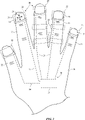
図2は、ユーザの手及び例示的な指装着デバイスの平面図である。図2に示すように、デバイス10は、ユーザの指32に装着された1つ以上の指装着ユニット22から形成され得る。ユニット22は、例えば、指32の先端に装着され得る(例えば、指の爪34に重ねて)。制御回路14の一部又は全部は、ユニット22に含まれ得る、又は別個の筐体構造体内に搭載され得る(例えば、リストバンドの一部、手袋、指無し手袋又はユーザの指先の腹の部分が除去されている手袋などの部分的手袋、など)。信号経路24などの信号経路は、ユニット22の回路及び/又はユニット22の外に配置される制御回路14などの追加の回路を、相互接続することに使用され得る。
FIG. 2 is a plan view of a user's hand and an exemplary finger-worn device. As shown in FIG. 2, the
信号経路24は、有線又は無線リンクを含み得る。有線経路は、例えば、フレキシブルプリント配線などのプリント配線の金属配線を用いて、配線を用いて、織られた、編まれた、又は編組されたファブリック状の導電性の撚線(例えば、配線若しくは金属被覆ポリマー撚線)を用いて、かつ/あるいは他の導電性の信号ラインを用いて、形成され得る。制御回路14の一部又は全部がユニット22の外に配置される構成では、信号経路24などの信号経路は、ユニット22の回路をこの制御回路に結合するために、ユーザの手30の一部又は全部にわたって流れ得る。制御回路10が1つ以上のユニット22内に配置され、これらのユニット22が有線又は無線経路24によって相互接続される構成が、所望であれば、使用され得る。
The
ユニット22がユーザの指先上に配置されているとき、ユニット22の構成要素は、ユーザの指先と外部面との間の接触を検知し得る。いくつかの構成では、ユーザの指先(例えば、ユーザの指先の腹)は、表面と接触し得て、指先が表面と接触している間、ユーザは、図2の横方向28及び26などの横方向へ、指先を横に移動させ得る。指先の腹が表面と接触している間の指先の横方向の動作(例えば、接触されている表面の平面に平行な次元での指先の動作)は、1つ以上のユニット22の構成要素によって検出され得るせん断力を発生させ得る。このことにより、ユーザの指先自体が、図1のデバイス20などのデバイスにおけるスクリーン上のカーソル又は他の調節可能なシステムの機能を制御し得る、ポインティングデバイスとして使用されること(例えば、ジョイスティックとして使用されること)が可能になる。いくつかの構成では、ユニット22は、指32の指先の他の手30の部分に装着され得る。例えば、ユニット22は、図2の例示的なユニット22’によって示されるように、指32の長さ方向に沿った他の部位に装着され得る。所望であれば、ユニット22及び22’は、デバイス10内で(例えば、複数の指の位置から情報を収集するために)同時に使用され得る。ユニット22が指32の先端に装着される例示的な構成が、一例として本明細書で説明されることがあり得る。
When the
ユニット22は、指32の指先を部分的に又は全体的に囲み得る。図3は、ユニット22の本体が指32を囲む(例えば、ユニット22が指32の上側、側面の部分、及び下側の指の腹部分を有する)配置でのユーザの指32上の例示的な指装着デバイス(ユニット22)の断面図である。図3のユニット22は、一例として、ユーザがユニット22を介して表面を感じることを可能にする、柔軟なエラストマ材料、ファブリック、又は他の弾性材料から形成され得る。所望であれば、センサ、触覚デバイス、及び/又は他の構成要素は、位置36のような位置の指32の腹の下に装着され得る。
The
所望であれば、ユニット22は、ユニット22がユーザの指の上部及び/又は側面だけを覆い、ユーザの指先の腹は露出され、デバイス10の何れの部分によっても覆われないようにする、U字型断面外形を有し得る。この種の構成のユニット22により、ユーザがユーザ自身の皮膚で表面に触れることが可能になり得て、それにより、デバイス10が使用される環境へのユーザの感度を向上させる。例えば、ユーザの指先の上面及び側面のみを覆うユニット22により、ユーザの指の腹が触れた、表面上の小さな表面欠陥、表面のテクスチャーのわずかな不規則性、及びユーザの指の腹が覆われる構成では不明瞭になり得る他の詳細を検出することが可能になり得る。
If desired, the
図4は、ユニット22の本体38がユーザの指先を部分的にのみ囲むように構成された指装着デバイス10の例示的なユニット22の斜視図である。図4に示すように、本体38は、側壁部40(例えば、ユーザの指の側面に接触する部分)などの側面部と、結合部42(例えば、ユーザの指先の上部を覆う、又は、いくつかの構成では、ユーザの指先の底部でユーザの指先の腹を覆う、わずかに曲がった部分)などの部分とを含み得る。部分42は、ユーザの指の対向する左右の側面に隣接する側壁部分40を支持し得る。任意選択の開口部44などの開口部が、金属部材又は他の本体38を形成する構造体を曲げることを容易にするために、本体38内に形成され得る。本体38は、本体38をユーザの指先上に装着することを容易にするために、先細りにされ得る(例えば、本体38は、幅W1のより広い部分と、W1より狭い幅W2を有するユーザの指の最も外側の先端の、より狭い部分とを有し得る)。
FIG. 4 is a perspective view of an
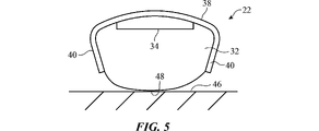
図5は、ユーザの指(例えば、指32の先端の底部にある指の腹48)が、表面46などの外部面上に軽く静止している構成での、図5のユニット22などの例示的なユニットの端面図である。図5に示すように、ユニット22の本体38は、本体38を指32に摩擦嵌合により保持する、U字型断面外形を有し得る。この構成を伴い、U字型本体38の開口側は、指の腹48を露出させるために、下方へ向き得る。
FIG. 5 is an example of the
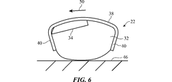
ユーザが指32を図6に示すように方向50で横方向へ移動させるとき、せん断力が生成される。力センサ(例えば、側壁40内の)は、このせん断力を検出し、ユーザの横方向の指の動作を測定するために検出されたせん断力を使用し得る。
Shear forces are generated when the user moves the
図7は、表面46に対する指押圧入力の力がどのように測定され得るかを示す。ユーザが表面46に対して指32を方向52で下方へ押圧するとき、指32の部分は、方向54で(例えば、対称的に)外側へ力を受けることになる。ユニット22の本体38の側壁部40内の力センサは、これらの外側への力を検出することができ、この情報を用いて、方向52に印加される下方への力の量を定量化できる。
FIG. 7 shows how the force of a finger press input to the
図8は、電気的構成要素の例示的な搭載位置を示す例示的な指装着ユニットの断面図である。図8に示すように、構成要素56は、本体38の内側及び/又は外側表面に搭載され得る(例えば、本体38の側壁部40及び/又は上部42)。一例として、力センサは、図6及び7に関連して説明したように、指の力を検出するために側壁部40に搭載され得る。別の例として、触覚出力デバイス18は、側壁部40に搭載され得る(例えば本体38の、外側面に、対向する内側壁面の対向する力センサに対面する内側面に、部分42の上部又は下部表面に、)。構成要素56は、加速度計、又は動作、向き、及び/若しくは指32の位置を検出する他のセンサを含み得る。例えば、加速度計は、部分42の上表面に又はユニット22内の他の部位に配置され得る。ユーザが、デバイス10に指タップ入力を供給するために、表面46(図7)上を軽くタップするとき、加速度計は、タップに対応するユニット22の速度の突然の変化(例えば、測定される加速度におけるピーク)を、検出し得る。力センサと加速度計との両方がデバイス10内に存在するとき、デバイス10は、指押圧入力(下方への力)、横方向の指動作入力(せん断力)、及び指タップ入力(加速度計出力信号のピーク)を測定できる。
FIG. 8 is a cross-sectional view of an exemplary finger mounting unit showing an exemplary mounting position of electrical components. As shown in FIG. 8, the
本体38によって支持され得る他の構成要素56は、ユニット22の位置及び/又は向きのカメラに基づく監視(例えば、デバイス20又は他の外部機器内の画像センサを用いた位置監視)を容易にするために、部分42の上面に又は本体38内の他の部位に、有線及び/又は無線通信回路及び/又は他の回路14用の構成要素(例えば、本体の部分42によって支持される回路)、電池、光学センサ(例えば、部分42上の発光及び光検出構成要素)、歪みゲージ(例えば、部分42の幅の一部又は全部にわたって延在し、側壁部40の部分42に対する移動からもたらされ、部分42の曲がった形状の平坦化に対応する、ひずみを測定するために、任意選択で部分42の上面に搭載され得る歪みゲージ)、及び/又は発光ダイオード若しくはパッシブマーカ構造体などの発光デバイスを含む。
図9は、図8の例示的な指装着ユニットの側面図である。図9に示すように、センサ又は他の構成要素56は、ユニット22の本体側壁部40の側面に沿ってセグメント化され得る。所望であれば、本体38によって支持されるセンサ又は他の構成要素56は、構成要素56’などの複数の副構成要素を有し得る。例えば、図9の側壁40上の力センサ及び/又は触覚装置は、各々が別個のそれぞれの力センサ測定値を生成する、かつ/又は各々が別個のそれぞれの触覚出力を生成する、複数の構成要素56’を有し得る。これにより、動作中に生み出される力に関するより詳細な測定値が作成されることが可能になり(例えば、ユーザの指の異なる部分が、図7の方向52の外側へ、どこを押圧するかを比較することによって、ユーザの指の先端内での指の押圧の位置に関する情報を正確に収集することを支援することが可能になる)、より詳細な触覚フィードバックがユーザに提供されることが可能になる。所望であれば、力センサなどの複数のセンサ及び/又は複数の触覚出力デバイス若しくは他の構成要素56’は、図10に示すように、本体38の上部42に配置され得る。
FIG. 9 is a side view of the exemplary finger mounting unit of FIG. As shown in FIG. 9, the sensor or
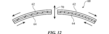
圧電構成要素は、力センサを形成すること(印加された力を制御回路14で処理する電気的信号に変換することによって)及び触覚出力デバイスを形成すること(制御回路14からの電気的信号をユーザの手に印加される力に変換することによって)に使用され得る。例示的な圧電デバイスを図11に示す。図11の圧電デバイス60は、部分66などのビーム形状の部分を有する支持構造体68などの支持構造体を有する。圧電レイヤ62及び64は、ビーム部分66の反対の表面に形成され得る。力センサでは、印加される力によるビーム66の曲がりが、読み取る力を生成するために回路14を用いて測定及び評価することが可能な、レイヤ62での圧縮応力、レイヤ64での引張応力を誘起することになる。触覚出力デバイスでは、レイヤ62を収縮させ、レイヤ64を拡張させ、それにより図12に示すように、ビーム部分66を反らせる、電圧が、制御回路14によってレイヤ62及び64に印加され得る。所望であれば、構成要素60などの圧電構成要素は、図12の例示的なディスク形状などの他の形状を有し得る。この種の配列の力センサでは、軸70に沿った構成要素60へ印加される力は、制御回路14によって測定可能である、レイヤ62及び64での圧縮及び引張応力を生成し得る。この種の配列の触覚出力デバイスでは、レイヤ62及び64に印加される電気的信号は、構成要素60を、軸70に沿って上下に反らせるために使用され得る。
Piezoelectric components form a force sensor (by converting the applied force into an electrical signal processed by the control circuit 14) and form a tactile output device (electrical signal from the control circuit 14). Can be used (by converting to a force applied to the user's hand). An exemplary piezoelectric device is shown in FIG. The
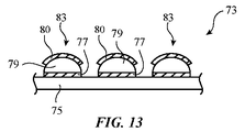
容量性の検知技術は、力を測定するために使用され得る。一例として、図13の容量性力センサを考える。容量性力センサ73は、基板75(例えば、可撓性又は剛性プリント回路、など)のような基板を有する。1つ以上の容量性力センサ83が、基板75上に形成され得る。例えば、基板75上の金属配線から形成された信号ラインを用いて制御回路14内の容量測定回路に結合された、力センサ構成要素83の一次元又は二次元のアレイが、基板75上に形成され得る。各容量性力センサ素子83は、圧縮可能な材料79(例えば、ポリマー発泡体、シリコーンなどのエラストマ材料、など)、によって分離される電極77及び80などの容量性の力検知電極を有し得る。制御回路14は、各素子83の電極対間のキャパシタンスを測定し得る。所与の素子83上に印加される力に応答して、その素子内の圧縮可能な材料79は、より薄くなることになり、電極間隔は、低減され、制御回路14が印加された力の大きさを決定するために測定可能であるキャパシタンスの増大をもたらす。
Capacitive detection techniques can be used to measure force. As an example, consider the capacitive force sensor of FIG. The
圧電構成要素を力の検知に使用すること及び/又は触覚出力を提供することに加えてあるいは代わりに、かつ容量性力センサの配置を力の検知に使用することに加えてあるいは代わりに、デバイス10は、他の力検知及び/又は触覚出力デバイスを使用し得る。例えば、力は、柔軟な圧電性ポリマー、微小電気機械システム(MEMs)、力センサ、歪みゲージ(例えば、部分42の表面に搭載される平坦な歪みゲージ)、抵抗性力センサ、圧力変動により皮膚の色変化を測定する光学センサ、及び/又は他の力検知構成要素を用いて検知され得る。触覚出力デバイスは、リニアソレノイド、非対称な質量を回転させるモーター、電気活性ポリマー、形状記憶合金に基づくアクチュエータ、空気圧アクチュエータなどの電磁アクチュエータ、及び/又は他の触覚出力構成要素に基づき得る。 Devices in addition to or instead of using piezoelectric components for force detection and / or providing tactile output, and in addition to or instead of using capacitive force sensor placement for force detection. 10 may use other force sensing and / or tactile output devices. For example, forces can be applied to flexible piezoelectric polymers, microelectromechanical systems (MEMs), force sensors, strain gauges (eg, flat strain gauges mounted on the surface of portion 42), resistance force sensors, pressure fluctuations on the skin. It can be detected using an optical sensor that measures the color change of and / or other force sensing components. Tactile output devices can be based on linear solenoids, motors that rotate asymmetric masses, electroactive polymers, actuators based on shape memory alloys, electromagnetic actuators such as pneumatic actuators, and / or other tactile output components.
図14に示すように、ユニット22は、部分42が指の爪34に隣接し、指の腹48が露出される配置で装着され得る。ユニット22は、ユーザの周囲での対象物を感知するユーザの能力を最大化することが所望されるとき、このように装着され得る。図15は、ユニット22が図14の向きと比較して上下反対で、部分42が指の腹48に隣接する、ひっくり返された配置で、どのようにユニット22が装着され得るかを示す。ユニット22は、本体38の触覚出力構成要素と指の腹48との間を結合して触覚を向上するために、このように装着され得る(例えば、デバイス10が仮想現実システムで使用されているとき、及び触覚出力がユーザに外部の表面とのユーザの実接触がない状態で提供されているとき)。図16は、ユニット22の側壁部が、どのようにフラップ40P又は40P’などの回転可能なフラップを有し得るかを示す。フラップは、位置40F(例えば、触覚出力デバイス又は他の構成要素56が指の腹48に隣接する位置)内に回転し得る。
As shown in FIG. 14, the
触覚出力は、ユニット22の触覚出力デバイスの変位での、1つ以上のパルスの形態で提供され得る。図17は、ユニット22の触覚出力デバイスを制御に使用され得る型の例示的な駆動信号DRのグラフである。図17の例では、駆動信号は、接近した間隔のパルス85の対(例えば、約100~300Hz、少なくとも150Hz、250Hz以下、又は他の好適な周波数の速さで発生する2つのパルス85)を含む。図17のパルス群(群86)内に2つのパルスが存在するが、所望であれば、より少ない又はより多いパルスが、駆動信号DR内に含まれ得る。人間の指は、通常、1~1000Hzの信号に感度を示し、特に1~300Hzの範囲の信号に敏感である。他の周波数の駆動信号DRも、しかしながら、所望であれば、使用され得る。各パルス85は、面取りされた正弦波の形状、ガウス形、又は他の好適な形状を有し得る。
The tactile output may be provided in the form of one or more pulses at the displacement of the tactile output device of the
図18は、ユニット22が、本体38の他の部分の支持を支援するフレーム部材88を有する、例示的な指装着デバイスの構成の斜視図である。フレーム部材88は、プラスチック又は金属薄板のレイヤなどの変形可能な構造体と重なる、変形可能な金属ワイヤなどの細長い構造体であり得る。フレーム部材88の存在により、ユーザの指32の先端上への本体38の満足できる摩擦嵌合を生成するために、ユーザが、本体38を制御可能に変形させることが可能になる。
FIG. 18 is a perspective view of the configuration of an exemplary finger-worn device in which the
図19の例では、空気圧構成要素90が、本体38の側壁部40の内側面に形成されている。膨張時に、空気圧構成要素90(例えば、気球)は、位置90’へと拡張し、これによりユニット22をユーザの指上に保持することを支援する。
In the example of FIG. 19, the
図20は、発泡体又は他の圧縮可能な材料(例えば、シリコーン又は他のエラストマ材料)のレイヤ(レイヤ92)が、本体38の側壁部40及び部分42の内側面に配置されている、ユニット22の例示的な構成の図である。ユニット22がユーザの指上に配置されているとき、圧縮性層92は、ユーザの指の形状に従い、ユニット22をユーザの指上に保持することを支援し得る。
FIG. 20 shows a unit in which a layer (layer 92) of a foam or other compressible material (eg, silicone or other elastomeric material) is disposed on the inner surface of the
図21は、どのように、ナット93などのねじが切られた締め具が、本体38をユーザの指上に固定することを支援するために、本体38の幅を調整することに使用され得るかを示す。ナット93は、本体部分42の部分98のねじ山で受けられ得る。ナット93が、軸94の回りで方向96に回転されるとき、本体部分42の部分98は、ナット93の回転方向により、引き寄せられる又は押し離されることになる。部分98が互いの方向へ引かれるとき、本体側壁部40は、方向100で内向きに偏倚されることになり、それによりユーザの指での本体側壁部40と固定ユニット22との間の分離距離を削減する。
FIG. 21 can be used to adjust the width of the
図22の例では、ユニット22は、互いに対して摺動する部分を有する。具体的には、本体部分42は、部分42-2などの第2の部分に対して摺動する、部分42-1などの第1の部分を有することで、ユニット22の幅を調整し、したがって側壁部40の分離距離を快適なサイズに調整し得る。部分42-1及び42-2のエリア102は、部分42-1及び42-2を同時に保持し、所望の配置でユニット22をユーザの指上に固定することを支援する、磁気引力を示し得る。
In the example of FIG. 22, the
図23は、どのように、ばね104などの偏倚構造体が、方向100で部分42-1及び42-2を互いの方向へ引き寄せ、ユニット22をユーザの指上に固定するかを示す。
FIG. 23 shows how a deviating structure, such as a
図24は、本体38が変形可能な金属層などの変形可能な構造体から形成される、例示的な構成にあるユニット22の側断面図である。この種の構成により、壁部40は、ユニット22をユーザの指上に固定されることが所望されるとき、方向100で内向きに位置40’などの位置へ曲げられ得る。この種の構成にある本体38は、エラストマ材料で被覆された金属層を含み得る。図25に示すように、例えば、本体38は、中央の金属層38M及びポリマーコーティング層38Pを含む。
FIG. 24 is a side sectional view of the
図26は、指32上にあるが、指32の先端で指の爪34と重ならない位置にある、例示的な指装着ユニット(ユニット22’)の側面図である。デバイス10は、1つ以上の指装着ユニットを有し得て、これらのユニットは、通常、ユーザの指先、ユーザの指32上の他の位置、などに配置され得る。
FIG. 26 is a side view of an exemplary finger mounting unit (unit 22') located on the
図27は、どのように、構成要素56が、ユーザの指32の裏上のエリア32Tなどのエリアからタッチ入力を収集し得る、光学センサを含み得るかを示す。光学センサは、発光ダイオード、レーザー、又は他の発光構成要素(例えば、赤外発光ダイオード)を含み得て、固体光検出器(例えば、フォトダイオード、ホトトランジスタ、など)などの光検出構成要素を含み得る。発光構成要素は、経路110に沿って発光し得て、光検出構成要素は、ユーザの指先又はこれらの経路110のうちの1つと交差する他の外部対象物の存在により反射される、経路110に沿った反射光を検出し得る。経路110は、互いに平行であり得て、かつ/又は斜めの経路(例えば、三角測量を容易にするために)を含み得る。この種の構成では、光学センサからの光学センサ信号を処理することによって、制御回路14は、エリア32Tでの対象物の位置を測定し得る(例えば、1又は2次元で)。これにより、エリア32Tが小型ポータブルトラックパッドとして用いられることが可能になる。
FIG. 27 shows how the
図28に示すように、システム12内の電子装置20などの外部機器が、1つ以上の71(例えば、可視光カメラ、赤外線カメラ、など)のようなセンサを含み得る。電子装置20は、一例として、拡張現実(複合現実)又は仮想現実のゴーグル(又はメガネ、ヘルメット、若しくは他のヘッドマウント支持構造体)などのヘッドマウントデバイスであり得る。ビジュアルマーカ72は、ユーザの作業環境内に配置され得る。マーカ72は、例えば、バーコード、十字記号、又は他の視覚的に識別可能なパターンなどのパッシブビジュアルマーカであり得て、卓上又は他の作業面に適用され得る。所望であれば、マーカ72は、パッド74などの作業面パッドの一部として形成され得る。マーカは、指装着デバイス10上に更に配置され得る(例えば、図28のユニット22を参照のこと)。
As shown in FIG. 28, an external device such as an
マーカ72は、所望であれば、カメラを用いて検出される発光構成要素(例えば、識別可能な変調コードを用いて変調された可視発光ダイオード及び/又は赤外発光ダイオード)を含み得る。マーカ72は、ユーザがシステム12内のコンピュータ又は他の機器と対話しているとき、システム10にユーザの仮想作業面及びユーザの指の1つ以上の位置を通知することを支援し得る。
The
ユニット22上のビジュアルマーカ72及び/又はユニット22内の慣性測定ユニット(例えば、加速度計、コンパス、及び/又はジャイロスコープ)は、ユーザの作業エリア上のマーカ72に対するユーザの指位置(例えば、指装着ユニット22の位置)を追跡することに使用され得る。同時に、システム10は、ユーザのために関連する視覚的コンテンツを表示し得る。ユーザは、力入力、動作入力(例えば、エアージェスチャ)、タップ、せん断力入力、並びにユニット22内の慣性測定ユニット及び/又はデバイス10内の力センサと他のセンサとによって、ユニット22から収集された他の入力を供給することによって、表示された視覚的コンテンツと対話し得る。
The
例えば、指装着ユニット22のマーカ72に対する位置に関する情報は、システム10の動作中、デバイス20内の制御回路又はシステム10内の他の電子機器(例えば、コンピュータ、セルラー電話機、又はデバイス20に結合された他の電子デバイス)によって収集され得て、一方、ユーザが、表示されたビジュアル要素を、選択した(例えば、強調表示した)、移動させた、又はそうでなければ操作したこと、及び/あるいはシステム12にコマンドを供給したことを示す、力入力、ジェスチャ入力(例えば、タップ、三次元エアージェスチャ、など)について、ユニット22を監視し得る。一例として、ユーザは、視覚的コンテンツを左に移動させるために、左手を振るなどのエアージェスチャを行い得る。システム10は、ユニット22の慣性測定ユニットを、左手を振るジェスチャを検出するために使用し得て、左手を振るジェスチャに応答して、デバイス20のディスプレイでユーザに提示されつつあるビジュアル要素を、移動させることができる。別の例として、ユーザは、ユーザの視野内のビジュアル要素を、その要素をタッピングすることによって、選択し得る。
For example, information about the position of the finger-worn
このようにしてデバイス20の制御回路、及び/又はシステム10の他の制御回路により、ユーザが、ユーザによって見られつつあるビジュアル要素(例えば、仮想現実コンテンツ、又は拡張現実のゴーグル若しくはディスプレイを用いた他のデバイス20などのヘッドマウントデバイスにより提示されつつある他の視覚的コンテンツ)を操作することが可能になり得る。所望であれば、カメラ71などのカメラは、ユーザの目に向かい得る(例えば、カメラ71又は他の視覚的追跡機器は、視線追跡システムの一部を形成し得る)。カメラ及び/又は視線追跡システムの他の回路は、ユーザが現実世界の対象物及び視覚的コンテンツを見つつある、方向を監視し得る。一例として、カメラは、ユーザがデバイス20によって提示される仮想コンテンツと対話するとき、及びユーザが現実生活のコンテンツと対話するとき、ユーザの目の注視点(視線方向)を監視するために使用され得る。デバイス20の制御回路、ユニット22、又は他の電子機器は、ユーザの視線が特定の位置に留まる時間を測定し得て、この注視点情報を、仮想オブジェクトの選択の時の決定に、使用し得る。仮想オブジェクトはまた、ユーザが特定の対象物を見ていることが判定されたとき(例えば、注視点情報を分析することによって)、及び見ている特定の対象物を選択するために、ユーザが、音声コマンド、指入力、ボタン押下入力、又は他のユーザ入力を行ったと判定されたとき、選択され得る。注視点情報はまた、ドラッグアンドドロップ動作中に使用され得る(例えば、注視点の移動により、仮想オブジェクトをあるシーンのある位置から別の位置に移動させるために)。
In this way, the control circuit of the
図29は、どのように、ビジュアル要素が、指32上に指装着デバイス22を装着しているユーザによって、操作され得るかを示す図である。例示的な要素76などのビジュアル要素(例えば、デスクトップアプリケーションを提示するアイコン、ファイルフォルダ、メディアファイル若しくは他のファイル、又は他の情報)が、デバイス20内のディスプレイを用いて表示され得る。作業空間74が、所望であれば、マーカ72を有し得る。ユーザは、タップ、力入力、持続的タッチ入力、エアージェスチャ、並びに/あるいはユニット22及び/又はデバイス20のカメラのようなシステム12の他の機器を使用して検出される、他のユーザ入力を用いて、視覚的項目を選択し得る。
FIG. 29 is a diagram showing how the visual elements can be manipulated by a user wearing the finger-worn
例示的な要素76などの視覚的項目は、選択され(例えば、アプリケーションを起動するために、項目を強調表示するために、など)、移動され、削除され、マーキングされ得て、かつ/又はそうでなければ、ジェスチャ(例えば、ドラッグアンドドロップのジェスチャ、など)及び他のユーザ入力を用いて、ユーザによって操作され得る。例えば、ユーザは、入力デバイスとして指32の先端を用いて、ビジュアル要素76を、作業空間74の位置78へ、ドラッグアンドドロップし得る(一方、指32の先端の位置は、ユニット22を用いて監視される)。指32上のユニット22は、触覚出力を提供し得る(例えば、ユーザが所定の境界を通り越して要素76をドラッグするとき仮想戻り止めをもたらすフィードバック)。このフィードバックは、視覚的フィードバックを伴い得る(例えば、触覚フィードバックと同期された、素子76の外観の色及び他の様相の変化)。所望であれば、デバイス20は、ビジュアル要素を、仮想作業空間74’によって示されるように、ユーザの前方に上方(並びに、所望であれば、左右側、及び/又は背後)へ延在する、仮想作業空間に表示し得る。ユーザは、ビジュアル要素76を、仮想作業空間74’内の位置へドラッグアンドドロップし得る(例えば、素子76を位置80に配置するために)。作業空間74’内の項目は、エアージェスチャ又は他の入力(例えば、音声入力、など)を用いて、操作され得る。例えば、ユーザは、作業空間74’内の項目を右に移動させるために、右へのスワイプを使用し得る。
Visual items such as the
ユーザが仮想コンテンツとユニット22を用いて対話するとき、ユーザは、テーブル面又は他の表面に、指32の表面で接触し得る。例えば、指32の先端の底部の指の腹48の指腹部は、テーブル面と接触し得て、指32によって付与される力によって圧縮され得る。指押圧入力を供給するとき、疲労を軽減し、ユーザの経験を向上させるために、ユーザが電子デバイスに入力を供給するときにユーザの指にかかる力は、ユーザの指に結合された構成要素及び/又は電子デバイス内の構成要素を用いて修正され得る。一例として、ユニット22などの指装着デバイス内の構成要素は、ユーザの指と入力面(作業空間74に関連付けられた面)との間の衝撃を和らげることを、支援するために使用され得る。
When the user interacts with the virtual content using the
修正されない指の衝撃事象は、急激な力対変位の形(例えば、比較的短い距離を入力面に向かって移動するときに、ユーザの指上に急速に立ち上がる力)によって特徴づけられ得る。これらの力を修正することによって、ユーザは、物理ボタン上のクリックのアクションを模倣する指感覚、及び/又は他の指感覚を用いて、より柔軟な指と入力面との相互作用が与えられ得る。ある例示的な構成を用いて、ユニット22内のアクチュエータ(例えば、圧電アクチュエータ、電気機械アクチュエータ)は、指先が表面にタッチする直前に、ユーザの指先を圧縮し得て(又は圧縮しない)、それにより指先が表面に接触したときのユーザの経験を選択的に修正する。例えば、ユニット22の左右のアクチュエータが、指の腹48が表面46にタッチする直前に、指32上で内向きに圧縮する場合、それにより指32の指腹部が、接触の前に表面46に向かって突き出され、ユーザは、アクチュエータが指上で内向きに圧縮しなかった場合に比べて、より軽減された表面46との衝撃を経験し得る。これらのような修正は、ユーザが仮想コンテンツと対話するとき、動的に行われ得る。
An uncorrected finger impact event can be characterized by a form of abrupt force vs. displacement (eg, a force that rises rapidly on the user's finger when traveling a relatively short distance towards the input surface). By modifying these forces, the user is given a more flexible finger-input surface interaction using finger sensations that mimic the action of a click on a physical button and / or other finger sensations. obtain. Using one exemplary configuration, an actuator within the unit 22 (eg, a piezoelectric actuator, an electromechanical actuator) may (or does not) compress the user's fingertip just before the fingertip touches the surface. Selectively modify the user's experience when the fingertip touches the surface. For example, if the left and right actuators of the
図30は、ビジュアル要素76が、複数の項目を含むリストであり得る様子を示す。リスト中の所望の項目は、指32を、所望の項目の上方に所定の時間以上留まらせる(遅らせる)ことによって、選択され得る(例示的な選択された項目76Hによって示されるように)。システム10によって収集された指の位置情報(例えば、ユニット22の慣性測定値、ユニット22のマーカのカメラ測定、など)は、どのリストの項目が選択され、強調表示されることになるかを判定することなどに使用され得る。ジェスチャは項目をスクロールするために用いられ得る。
FIG. 30 shows how the
所望であれば、システム10(例えば、デバイス20のカメラ、など)は、ユニット22の位置を、光学的検知を用いて、検出し得る。図31に示すように、ユニット22は、ビジュアルマーカ72(例えば、パッシブマーカ、可視又は赤外発光ダイオード、など)を含み得る。マーカ72は、部分42及び40などのデバイス10内のユニット22の部分に配置され得る。マーカ72は、不明瞭な位置データの作成を避けることを支援するために、認識可能な非対称パターンで構成され得る。
If desired, the system 10 (eg, the camera of the device 20) may detect the position of the
図32は、上部部分42が、構成要素56が収容されている、厚い部分42Nと、薄い部分42Tなどの曲げることを容易にする薄い部分とを有する、例示的な構成にあるユニット22の側断面図である。薄い部分42Tは、金属、ポリマー、などの弾性材料及び/又は他の材料から形成され得て、部分42N間に挿入され得る。
FIG. 32 shows the side of a
所望であれば薄い部分42T及び/又はユニット22の他の部分は、調節可能な可撓性を有する構成要素から形成され得る。調節可能な可撓性を有する例示的な構成要素が、図33に示されている。図33に示すように、構成要素80(例えば、電気的に調節可能な可撓性を有するレイヤ)は、電極84が介挿された電気活性ポリマーの複数のレイヤ82を有し得る。電極84に小信号が印加されるとき又は信号が印加されないとき、レイヤ82は、互いに対して滑り得て、構成要素80は、可撓性を有する。より大きな信号が電極84に印加されるとき、レイヤ82は位置が固定され、構成要素80は可撓性を有さないことになる。構成要素80は、図32のユニット22の部分42Tに配置され得る。電圧が印加されないとき、部分42Tは、曲がることが可能であり、ユニット22がユーザの指上に配置されることを可能にする。ユニット22が、ユーザの指上に配置されたあと、ユニット22は、制御信号を電極84に印加することにより、指上の位置に固定され得る。
If desired, the
一実施形態によれば、ユーザの指に装着されるように構成され、その指は、一面に指の爪を、反対の面に指の腹を伴う指先を有する、指装着デバイスであって、指先に結合するように構成され、その指先の指の爪を覆い、その指先の指の腹を露出されたままにする本体と、本体と結合された触覚出力デバイスと、触覚出力をユーザの指に触覚出力デバイスを用いて提供するように構成された制御回路とを含む、指装着デバイスが提供される。 According to one embodiment, a finger-wearing device configured to be worn on a user's finger, the finger having a fingernail on one side and a fingertip with a finger pad on the other side. A body that is configured to connect to the fingertips and covers the fingernails of the fingertips, leaving the pad of the fingertips exposed, a tactile output device coupled to the body, and the tactile output of the user's finger. A finger-worn device is provided, including a control circuit configured to provide with a tactile output device.
別の実施形態によれば、制御回路は、加速度計を用いて指タップ入力を収集するように構成される。 According to another embodiment, the control circuit is configured to collect finger tap inputs using an accelerometer.
別の実施形態によれば、指装着デバイスは、力センサを含み、制御回路は、指で表面に印加された指圧に関連付けられた、力センサからの指タップ情報及び力情報を無線送信するように構成された、無線通信回路を含む。 According to another embodiment, the finger-worn device comprises a force sensor and the control circuit wirelessly transmits finger tap information and force information from the force sensor associated with the finger pressure applied to the surface with the finger. Includes a wireless communication circuit configured in.
別の実施形態によれば、指装着デバイスは、本体に結合された光学センサを含む。 According to another embodiment, the finger-worn device comprises an optical sensor coupled to the body.
別の実施形態によれば、指装着デバイスは、本体に結合された発光ダイオードを含む。 According to another embodiment, the finger-worn device comprises a light emitting diode coupled to the body.
別の実施形態によれば、本体は、互いに対し移動するように構成された第1及び第2の本体部分を含み、指装着デバイスは、第1及び第2の本体部分を引き寄せるように構成された、第1及び第2の本体部分間を連結する、偏倚構造体を含む。 According to another embodiment, the body includes first and second body portions configured to move relative to each other, and the finger-worn device is configured to attract the first and second body portions. It also includes a deviated structure that connects the first and second body parts.
別の実施形態によれば、本体は、ポリマーで被覆された変形可能な金属層を含む。 According to another embodiment, the body comprises a deformable metal layer coated with a polymer.
別の実施形態によれば、本体は、互いに対して移動するように構成された、第1及び第2の本体部分を含み、第1及び第2の本体部分を互いに結合する磁石部分を含む。 According to another embodiment, the body comprises a first and second body portions configured to move relative to each other and a magnet portion that couples the first and second body portions to each other.
別の実施形態によれば、指装着デバイスは、本体の内側面に圧縮性層を含む。 According to another embodiment, the finger-worn device comprises a compressible layer on the inner surface of the body.
別の実施形態によれば、指装着デバイスは、本体に結合された力センサを含み、制御回路は、指によって印加された圧力に関連付けられた力測定値を、力センサを用いて収集するように構成される。 According to another embodiment, the finger-worn device comprises a force sensor coupled to the body and the control circuit is such that the force measurement associated with the pressure applied by the finger is collected using the force sensor. It is composed of.
別の実施形態によれば、制御回路は、力測定値に基づいた触覚出力を提供するように構成される。 According to another embodiment, the control circuit is configured to provide a tactile output based on force measurements.
別の実施形態によれば、本体は、側壁部と、側壁部を互いに結合する部分とを有し、力センサは、側壁部のうちの1つに搭載され、触覚出力デバイスは、側壁部のうちの1つに搭載される。 According to another embodiment, the main body has a side wall portion and a portion that connects the side wall portions to each other, a force sensor is mounted on one of the side wall portions, and a tactile output device is a side wall portion. It will be installed in one of them.
別の実施形態によれば、力センサは、圧電力センサを含む。 According to another embodiment, the force sensor includes a pressure power sensor.
別の実施形態によれば、力センサは、容量性力センサを含む。 According to another embodiment, the force sensor includes a capacitive force sensor.
別の実施形態によれば、触覚出力デバイスは、圧電触覚出力デバイスを含む。 According to another embodiment, the tactile output device includes a piezoelectric tactile output device.
別の実施形態によれば、触覚出力デバイスは、制御回路への力センサ入力を収集するように構成される。 According to another embodiment, the tactile output device is configured to collect force sensor inputs to the control circuit.
別の実施形態によれば、指装着電子デバイスは、力センサと加速度計とを含み、制御回路は、力センサ及び加速度計のうちの選択された1つからの出力の検出に応答して、1~300Hzの周波数のパルスで触覚出力デバイスを駆動するように構成される。 According to another embodiment, the finger-worn electronic device comprises a force sensor and an accelerometer, and the control circuit responds to the detection of an output from a selected one of the force sensor and the accelerometer. It is configured to drive the tactile output device with a pulse with a frequency of 1 to 300 Hz.
別の実施形態によれば、触覚出力デバイスは、力センサ測定値を制御回路に供給するように構成される。 According to another embodiment, the tactile output device is configured to supply force sensor measurements to the control circuit.
別の実施形態によれば、触覚出力は、仮想現実触覚出力及び拡張現実触覚出力から成る群から選択される触覚出力を含む。 According to another embodiment, the tactile output includes a tactile output selected from the group consisting of a virtual reality tactile output and an augmented reality tactile output.
一実施形態によれば、力センサと、触覚出力デバイスと、加速度計と、支持構造体を有する指先ユニットであって、支持構造体が、力センサと、触覚出力デバイスと、加速度計とに結合された、指先ユニットと、力センサ及び加速度計から情報を収集するように構成されると共に、駆動信号を触覚出力デバイスへ供給するように構成された制御回路とを含む、指装着デバイスが提供される。 According to one embodiment, a force sensor, a tactile output device, an accelerometer, and a fingertip unit having a support structure, wherein the support structure is coupled to the force sensor, the tactile output device, and the accelerometer. A finger-worn device is provided that includes a fingertip unit and a control circuit configured to collect information from force sensors and accelerometers and to supply drive signals to tactile output devices. To.
別の実施形態によれば、制御回路は、それを用いて制御回路が、力センサ及び加速度計からの情報を無線送信する、無線回路を有する。 According to another embodiment, the control circuit comprises a wireless circuit using which the control circuit wirelessly transmits information from a force sensor and an accelerometer.
別の実施形態によれば、支持構造体は、ユーザの指先に結合するが、指先の指の腹の部分は露出されたままとなるように構成されたU字型断面外形を有する。 According to another embodiment, the support structure has a U-shaped cross-sectional outline configured to be coupled to the user's fingertip, but the portion of the finger pad of the fingertip remains exposed.
一実施形態によれば、第1及び第2の部分を伴うU字型断面外形を有し、第1及び第2の部分が、第3の部分によって結合される側壁を形成する、指装着支持構造体と、第1の部分上に配置された力センサと、第3の部分上に配置された加速度計と、指装着支持構造体に結合された触覚出力デバイスとを含む、装置が提供される。 According to one embodiment, a finger-mounted support having a U-shaped cross-sectional outline with first and second portions, the first and second portions forming a sidewall coupled by the third portion. A device is provided that includes a structure, a force sensor placed on a first portion, an accelerometer placed on a third portion, and a tactile output device coupled to a finger-mounted support structure. To.
別の実施形態によれば、指装着支持構造体は、第1及び第2の部分間の分離距離を調節するために変形するように構成された、変形可能な金属層を有する。 According to another embodiment, the finger-mounted support structure has a deformable metal layer configured to be deformed to adjust the separation distance between the first and second portions.
別の実施形態によれば、第3の部分は、第1及び第2の部分間の分離距離を調整するために、互いに対して摺動する部分を有する。 According to another embodiment, the third portion has a portion that slides relative to each other in order to adjust the separation distance between the first and second portions.
別の実施形態によれば、第3の部分は、電気的に調節可能な可撓性を有する構成要素を含む。 According to another embodiment, the third portion comprises an electrically adjustable flexible component.
別の実施形態によれば、この装置は、指装着支持構造体の動作を追跡するカメラを有し、ビジュアル要素を表示するように構成された、電子デバイスを含む。 According to another embodiment, the device comprises an electronic device that comprises a camera that tracks the movement of a finger-mounted support structure and is configured to display visual elements.
別の実施形態によれば、この電子デバイスは、ビジュアル要素を表示するディスプレイを有するヘッドマウントデバイスを含み、ヘッドマウントデバイスは、加速度計からの情報に基づいて、表示されたビジュアル要素をディスプレイ上で移動させるように構成される。 According to another embodiment, the electronic device includes a head-mounted device having a display that displays the visual elements, which are based on information from the accelerometer to display the displayed visual elements on the display. It is configured to move.
別の実施形態によれば、この電子デバイスは、ビジュアル要素を表示するディスプレイを有するヘッドマウントデバイスを含み、ヘッドマウントデバイスは、力センサからの情報に基づいて、表示されたビジュアル要素をディスプレイ上で移動させつつ、フィードバックとして触覚出力デバイスを用いて触覚出力を供給するように構成される。 According to another embodiment, the electronic device includes a head mount device having a display that displays the visual elements, the head mount device is based on information from a force sensor to display the displayed visual elements on the display. It is configured to supply tactile output using a tactile output device as feedback while moving.
別の実施形態によれば、この装置は、カメラを用いて追跡されるビジュアルマーカを含む。 According to another embodiment, the device comprises a visual marker that is tracked using a camera.
別の実施形態によれば、このビジュアルマーカは、指装着支持構造体上の赤外発光ダイオードを含む。 According to another embodiment, the visual marker comprises an infrared light emitting diode on a finger-mounted support structure.
前述は、単に例示であり、多様な変更が、説明された実施形態になされ得る。前述の実施形態は、個別に又は任意の組合せで実施され得る。
The above is merely exemplary and various modifications can be made to the embodiments described. The aforementioned embodiments may be implemented individually or in any combination.
Claims (20)
前記指先に結合するように構成される本体であって、前記本体は、前記指先の前記指の爪を覆う第1の部分と、前記指先の第1の側部を下に伸びる第2の部分と、前記指先の第2の側部を下に伸びる第3の部分とを有し、前記本体は、前記指先の前記指の腹を露出されたままにし、前記第2の部分と前記第3の部分は前記指先に取り付けるために互いに対して移動するように構成される、本体と、
前記本体の前記第2の部分におけるセンサであって、前記センサは、前記指先の前記第1の側部に沿う異なる大きさの圧縮に基づいて各々が別個のそれぞれの力センサ測定値を生成する複数の構成要素を含む力センサを含む、センサと、
前記本体と結合された触覚出力デバイスと、
制御回路であって、
前記複数の構成要素を含む前記力センサを用いて指入力を収集し、
触覚出力を前記ユーザの指に、前記触覚出力デバイスを用いて提供し、
前記指入力に基づいて制御信号を外部電子デバイスに送信する、ように構成された制御回路とを、備える、指装着デバイス。 A finger-wearing device configured to be worn on a user's finger, said fingernail having a fingernail on one side and a fingertip having a fingernail on the other side.
A main body configured to be coupled to the fingertip, the main body has a first portion of the fingernail covering the fingernail and a second portion extending downward from the first side portion of the fingertip. And a third portion extending downward from the second side of the fingernail, the body of which leaves the pad of the fingernail of the fingernail exposed, the second portion and the third portion. The parts of the body and the body are configured to move relative to each other for attachment to the fingertips.
Sensors in the second portion of the body, each producing a separate force sensor measurement based on different magnitudes of compression along the first side of the fingertip. Sensors, including force sensors containing multiple components, and
The tactile output device coupled to the main body,
It ’s a control circuit,
Finger input is collected using the force sensor containing the plurality of components .
Tactile output is provided to the user's finger using the tactile output device.
A finger-worn device comprising a control circuit configured to transmit a control signal to an external electronic device based on the finger input.
前記本体に結合された発光ダイオードとを更に備える、請求項1に記載の指装着デバイス。 The optical sensor coupled to the main body and
The finger-mounted device according to claim 1, further comprising a light emitting diode coupled to the main body.
力センサと、
触覚出力デバイスと、
加速度計と、
前記指先の指の爪に重なる上部分と、前記指先の指の腹を露出されたままにして前記指先の互いに反対側にある第1の側と第2の側を下に伸びる2つの側部と、を有する支持構造体を有する指先ユニットであって、前記2つの側部が、前記指先に取り付けるために互いに対して移動するように構成され、前記支持構造体の前記2つの側部のうちの1つが、前記力センサであって、前記指先の前記第1の側又は前記第2の側に沿う異なる大きさの圧縮に基づいて各々が別個のそれぞれの力センサ測定値を生成する複数の構成要素を含む前記力センサと結合され、前記支持構造体が、前記触覚出力デバイスと、前記加速度計とに結合される、指先ユニットと、
前記複数の構成要素を含む前記力センサ及び前記加速度計から指入力を収集するように構成されると共に、駆動信号を前記触覚出力デバイスへ供給するように構成された制御回路とを備え、前記制御回路は、無線回路を備え、前記無線回路を用いて前記制御回路が、前記指入力に基づいて制御信号を外部電子デバイスに無線送信する、指装着デバイス。 A finger-worn device configured to be worn on a user's fingertip, said finger-worn device.
With a force sensor,
Tactile output device and
Accelerometer and
The upper part of the fingertip that overlaps the finger claw and the two side parts that extend downward on the first side and the second side of the fingertip on opposite sides of the fingertip, leaving the pad of the finger exposed. A fingertip unit having a support structure having One is the force sensor , each of which produces a separate force sensor measurement based on different magnitudes of compression along the first or second side of the fingertip. A fingertip unit coupled to the force sensor comprising the component and the support structure coupled to the tactile output device and the accelerometer.
The control includes a control circuit configured to collect finger inputs from the force sensor and the accelerometer including the plurality of components and to supply a drive signal to the tactile output device. The circuit is a finger-mounted device comprising a wireless circuit, wherein the control circuit wirelessly transmits a control signal to an external electronic device based on the finger input.
前記第1の部分上に配置された力センサであって、前記指先の側部に沿う異なる大きさの圧縮に基づいて各々が別個のそれぞれの力センサ測定値を生成する複数の構成要素を含む力センサと、
前記第3の部分上に配置された加速度計と、
前記指装着支持構造体に結合された触覚出力デバイスと、
前記複数の構成要素を含む前記力センサ及び前記加速度計から指入力を収集し、前記指入力に基づいて制御信号を外部電子デバイスに送信する制御回路とを備える、装置。 It has a U-shaped cross-sectional outline with a first portion and a second portion, wherein the first portion and the second portion are on the side of the fingertip while leaving the pad of the finger of the user's finger exposed. The sidewalls form a side wall that extends downwards, the sidewalls are joined by a third portion, and the first portion and the second portion are configured to move relative to each other for attachment to the fingertips. Finger-mounted support structure and
A force sensor located on the first portion , comprising a plurality of components each producing a separate force sensor measurement based on different magnitudes of compression along the sides of the fingertip. With a force sensor ,
With the accelerometer placed on the third part,
A tactile output device coupled to the finger-mounted support structure,
A device comprising the force sensor including the plurality of components and a control circuit that collects finger inputs from the accelerometer and transmits a control signal to an external electronic device based on the finger inputs.
ビジュアルマーカが前記カメラを用いて追跡され、前記ビジュアルマーカは、前記指装着支持構造体上の赤外発光ダイオードを含む、請求項15に記載の装置。 The external electronic device has a camera that tracks the movement of the finger-mounted support structure and is configured to display a visual element, and the external electronic device is a head mount having a display that displays the visual element. The head mount device, including the device, is configured to provide tactile output using the tactile output device as feedback while moving the displayed visual element on the display based on the finger input. ,
15. The apparatus of claim 15, wherein the visual marker is tracked using the camera, wherein the visual marker comprises an infrared light emitting diode on the finger-mounted support structure.
Applications Claiming Priority (5)
| Application Number | Priority Date | Filing Date | Title |
|---|---|---|---|
| US201762526792P | 2017-06-29 | 2017-06-29 | |
| US62/526,792 | 2017-06-29 | ||
| US16/015,043 US10838499B2 (en) | 2017-06-29 | 2018-06-21 | Finger-mounted device with sensors and haptics |
| US16/015,043 | 2018-06-21 | ||
| PCT/US2018/038845 WO2019005586A1 (en) | 2017-06-29 | 2018-06-21 | Finger-mounted device with sensors and haptics |
Related Child Applications (1)
| Application Number | Title | Priority Date | Filing Date |
|---|---|---|---|
| JP2021017706A Division JP7265567B2 (en) | 2017-06-29 | 2021-02-05 | Finger-worn device using sensor and tactile sense |
Publications (3)
| Publication Number | Publication Date |
|---|---|
| JP2019526864A JP2019526864A (en) | 2019-09-19 |
| JP2019526864A5 JP2019526864A5 (en) | 2019-11-14 |
| JP7086940B2 true JP7086940B2 (en) | 2022-06-20 |
Family
ID=64738080
Family Applications (3)
| Application Number | Title | Priority Date | Filing Date |
|---|---|---|---|
| JP2019511729A Active JP7086940B2 (en) | 2017-06-29 | 2018-06-21 | Finger-worn device with sensor and tactile sensation |
| JP2021017706A Active JP7265567B2 (en) | 2017-06-29 | 2021-02-05 | Finger-worn device using sensor and tactile sense |
| JP2023001243A Active JP7464762B2 (en) | 2017-06-29 | 2023-01-06 | Finger-worn device using sensors and tactile sensation |
Family Applications After (2)
| Application Number | Title | Priority Date | Filing Date |
|---|---|---|---|
| JP2021017706A Active JP7265567B2 (en) | 2017-06-29 | 2021-02-05 | Finger-worn device using sensor and tactile sense |
| JP2023001243A Active JP7464762B2 (en) | 2017-06-29 | 2023-01-06 | Finger-worn device using sensors and tactile sensation |
Country Status (7)
| Country | Link |
|---|---|
| US (3) | US10838499B2 (en) |
| EP (1) | EP3485355A1 (en) |
| JP (3) | JP7086940B2 (en) |
| KR (3) | KR20230074849A (en) |
| CN (3) | CN114578964A (en) |
| TW (1) | TWI706313B (en) |
| WO (1) | WO2019005586A1 (en) |
Families Citing this family (31)
| Publication number | Priority date | Publication date | Assignee | Title |
|---|---|---|---|---|
| KR20230074849A (en) | 2017-06-29 | 2023-05-31 | 애플 인크. | Finger-mounted device with sensors and haptics |
| US11886473B2 (en) | 2018-04-20 | 2024-01-30 | Meta Platforms, Inc. | Intent identification for agent matching by assistant systems |
| US11010179B2 (en) | 2018-04-20 | 2021-05-18 | Facebook, Inc. | Aggregating semantic information for improved understanding of users |
| US11360558B2 (en) | 2018-07-17 | 2022-06-14 | Apple Inc. | Computer systems with finger devices |
| JP7124616B2 (en) * | 2018-10-03 | 2022-08-24 | コニカミノルタ株式会社 | Guidance devices, control systems and control programs |
| US20220031414A1 (en) * | 2018-10-12 | 2022-02-03 | Sony Corporation | Medical system, method and computer program |
| JP7271245B2 (en) * | 2019-03-18 | 2023-05-11 | 株式会社ソニー・インタラクティブエンタテインメント | input device |
| WO2020251565A1 (en) * | 2019-06-12 | 2020-12-17 | Hewlett-Packard Development Company, L.P. | Finger clip biometric virtual reality controllers |
| US11422638B2 (en) | 2019-07-08 | 2022-08-23 | Apple Inc. | Input devices that use self-mixing interferometry to determine movement within an enclosure |
| US11163340B2 (en) | 2019-07-09 | 2021-11-02 | Apple Inc. | Electronic devices with fiber composite friction hinges |
| GB201912546D0 (en) * | 2019-08-31 | 2019-10-16 | Tada Ryo | Method and apparatus for wearable remote commuincation device |
| US11409365B2 (en) | 2019-09-06 | 2022-08-09 | Apple Inc. | Self-mixing interferometry-based gesture input system including a wearable or handheld device |
| US20210089131A1 (en) * | 2019-09-23 | 2021-03-25 | Apple Inc. | Finger-Mounted Input Devices |
| US11740742B2 (en) * | 2019-09-23 | 2023-08-29 | Apple Inc. | Electronic devices with finger sensors |
| US11419546B2 (en) | 2019-09-24 | 2022-08-23 | Apple Inc. | Wearable self-mixing interferometry device used to sense physiological conditions |
| US11893164B2 (en) * | 2019-10-18 | 2024-02-06 | Trustees Of Dartmouth College | Methods and systems for eyes-free text entry |
| CN111309145B (en) * | 2020-02-05 | 2021-03-23 | 吉林大学 | Electrostatic force touch rendering method based on physiological and physical modeling |
| US20230350491A1 (en) * | 2020-03-13 | 2023-11-02 | Sony Group Corporation | Information processing device, information processing method, and information processing program |
| US11360587B1 (en) | 2020-04-07 | 2022-06-14 | Apple Inc. | Deployment systems for computer system finger devices |
| US11502713B2 (en) | 2020-09-16 | 2022-11-15 | Genki Instruments ehf. | Smart ring |
| WO2022061263A1 (en) * | 2020-09-21 | 2022-03-24 | Daedalus Labs Llc | Systems having peripherals with magnetic field tracking |
| US11301041B1 (en) | 2020-09-30 | 2022-04-12 | International Business Machines Corporation | Hand tremor accessible using augmented reality user interface |
| JP7364097B2 (en) | 2020-11-06 | 2023-10-18 | 日本電信電話株式会社 | Force control support device, force control support method, and program |
| CN114779930A (en) * | 2021-04-14 | 2022-07-22 | 三峡大学 | Emotion recognition method for VR user touch experience based on one-to-many support vector machines |
| CN113268385B (en) * | 2021-05-21 | 2023-05-12 | 中国船舶工业综合技术经济研究院 | Multi-finger pressing force phase coordination capacity measurement system and method based on visual sense |
| IT202100016157A1 (en) * | 2021-06-21 | 2022-12-21 | Univ Del Salento | Wearable haptic system |
| JPWO2023286316A1 (en) * | 2021-07-14 | 2023-01-19 | ||
| US11452354B1 (en) * | 2021-08-28 | 2022-09-27 | Marta Magnusson | Electronic fingernail display |
| TWI802441B (en) * | 2022-06-14 | 2023-05-11 | 宏達國際電子股份有限公司 | Handheld controller |
| WO2024042502A1 (en) | 2022-08-26 | 2024-02-29 | Genki Instrument Ehf. | Improved smart ring |
| TWI821062B (en) * | 2022-12-05 | 2023-11-01 | 和碩聯合科技股份有限公司 | Control device and electronic device |
Citations (11)
| Publication number | Priority date | Publication date | Assignee | Title |
|---|---|---|---|---|
| JP2001104256A (en) | 1999-10-04 | 2001-04-17 | Toriumu Kk | Finger touch pressure sensor |
| JP2008171409A (en) | 2006-12-12 | 2008-07-24 | Toyota Motor Corp | Method for acting on tactile sensation, and tactile sensation device and variable bending mechanism for realizing the method |
| US20090096746A1 (en) | 2007-10-12 | 2009-04-16 | Immersion Corp., A Delaware Corporation | Method and Apparatus for Wearable Remote Interface Device |
| US20110213664A1 (en) | 2010-02-28 | 2011-09-01 | Osterhout Group, Inc. | Local advertising content on an interactive head-mounted eyepiece |
| WO2012176610A1 (en) | 2011-06-22 | 2012-12-27 | 株式会社村田製作所 | Finger stimulus presentation device |
| JP2013003782A (en) | 2011-06-15 | 2013-01-07 | Shiseido Co Ltd | Movement detection sensor |
| JP2014142751A (en) | 2013-01-23 | 2014-08-07 | Seiko Epson Corp | Display device, head-mounted type display device, and method for controlling display device |
| JP2015521303A (en) | 2012-03-30 | 2015-07-27 | ザ ボード オブ トラスティーズ オブ ザ ユニヴァーシ | An electronic device that can be attached to the surface and can be attached to an accessory |
| JP2015219887A (en) | 2014-05-21 | 2015-12-07 | 日本メクトロン株式会社 | Electric tactile presentation device |
| JP2016033815A (en) | 2014-07-30 | 2016-03-10 | エルジー エレクトロニクス インコーポレイティド | Ring-type mobile terminal |
| JP2016118929A (en) | 2014-12-19 | 2016-06-30 | 富士通株式会社 | Input support method, input support program and input support apparatus |
Family Cites Families (64)
| Publication number | Priority date | Publication date | Assignee | Title |
|---|---|---|---|---|
| US5631861A (en) | 1990-02-02 | 1997-05-20 | Virtual Technologies, Inc. | Force feedback and texture simulating interface device |
| US5581484A (en) | 1994-06-27 | 1996-12-03 | Prince; Kevin R. | Finger mounted computer input device |
| AU1328597A (en) * | 1995-11-30 | 1997-06-19 | Virtual Technologies, Inc. | Tactile feedback man-machine interface device |
| US6388247B2 (en) | 1998-02-20 | 2002-05-14 | Massachusetts Institute Of Technology | Fingernail sensors for measuring finger forces and finger posture |
| US20030214481A1 (en) | 2002-05-14 | 2003-11-20 | Yongming Xiong | Finger worn and operated input device and method of use |
| JP4085691B2 (en) * | 2002-05-17 | 2008-05-14 | セイコーエプソン株式会社 | Image processing device |
| US7042438B2 (en) | 2003-09-06 | 2006-05-09 | Mcrae Michael William | Hand manipulated data apparatus for computers and video games |
| KR100682901B1 (en) | 2004-11-17 | 2007-02-15 | 삼성전자주식회사 | Apparatus and method for providing fingertip haptics of visual information using electro-active polymer in a image displaying device |
| ITPI20040084A1 (en) | 2004-11-18 | 2005-02-18 | Massimo Bergamasco | PORTABLE APTIC INTERFACE |
| JP4029410B2 (en) * | 2006-05-05 | 2008-01-09 | 治幸 岩田 | Input device with fingertip wearing sensor |
| US20090278798A1 (en) | 2006-07-26 | 2009-11-12 | The Research Foundation Of The State University Of New York | Active Fingertip-Mounted Object Digitizer |
| GB2442973A (en) | 2006-10-20 | 2008-04-23 | Kevin Moonie | Finger worn computer mouse with an optical sensor on a pivoting arm |
| CA2591808A1 (en) * | 2007-07-11 | 2009-01-11 | Hsien-Hsiang Chiu | Intelligent object tracking and gestures sensing input device |
| US20110210931A1 (en) | 2007-08-19 | 2011-09-01 | Ringbow Ltd. | Finger-worn device and interaction methods and communication methods |
| WO2009024971A2 (en) * | 2007-08-19 | 2009-02-26 | Saar Shai | Finger-worn devices and related methods of use |
| JP2009104428A (en) * | 2007-10-24 | 2009-05-14 | Nikon Corp | Head mount display device and portable device |
| US20090153477A1 (en) | 2007-12-12 | 2009-06-18 | Saenz Valentin L | Computer mouse glove |
| US20150205417A1 (en) * | 2008-01-04 | 2015-07-23 | Tactus Technology, Inc. | Dynamic tactile interface |
| US8032730B2 (en) | 2008-05-15 | 2011-10-04 | Hitachi, Ltd. | Method and apparatus for I/O priority control in storage systems |
| JP2012503244A (en) | 2008-09-20 | 2012-02-02 | リングボー,エルティーディー. | Device worn on finger, interaction method and communication method |
| US8610548B1 (en) | 2009-02-03 | 2013-12-17 | University Of Utah Research Foundation | Compact shear tactile feedback device and related methods |
| KR20130101975A (en) | 2010-04-16 | 2013-09-16 | 니콜라스 제이 마스탄드리아 | Wearable motion sensing computing interface |
| FR2962566B1 (en) | 2010-07-06 | 2013-05-17 | Commissariat Energie Atomique | SIMULATION SYSTEM FOR CONTACT WITH A SURFACE BY TOUCH STIMULATION |
| US8724861B1 (en) | 2010-12-06 | 2014-05-13 | University Of South Florida | Fingertip force, location, and orientation sensor |
| US20120249419A1 (en) | 2011-03-30 | 2012-10-04 | Bronner Sr Dennis M | Thumb mountable cursor control and input device |
| US9104271B1 (en) | 2011-06-03 | 2015-08-11 | Richard Adams | Gloved human-machine interface |
| JP5624530B2 (en) | 2011-09-29 | 2014-11-12 | 株式会社東芝 | Command issuing device, method and program |
| KR101320176B1 (en) * | 2011-12-26 | 2013-10-23 | 삼성전기주식회사 | Haptic feedback device |
| US9317123B2 (en) | 2012-06-13 | 2016-04-19 | University Of Utah Research Foundation | Skin stretch feedback devices, systems, and methods |
| US9968297B2 (en) * | 2012-06-14 | 2018-05-15 | Medibotics Llc | EEG glasses (electroencephalographic eyewear) |
| US9891718B2 (en) * | 2015-04-22 | 2018-02-13 | Medibotics Llc | Devices for measuring finger motion and recognizing hand gestures |
| KR20140016122A (en) | 2012-06-22 | 2014-02-07 | 한국전자통신연구원 | Finger-mounted type apparatus for transmitting and receiving data |
| US9530232B2 (en) * | 2012-09-04 | 2016-12-27 | Qualcomm Incorporated | Augmented reality surface segmentation |
| US8994827B2 (en) | 2012-11-20 | 2015-03-31 | Samsung Electronics Co., Ltd | Wearable electronic device |
| JP6114562B2 (en) | 2013-01-22 | 2017-04-12 | 株式会社 資生堂 | Motion detection sensor and motion detection device |
| CN105473021B (en) | 2013-03-15 | 2018-01-19 | 智能专利有限责任公司 | wearable device and related system |
| US9092954B2 (en) | 2013-03-15 | 2015-07-28 | Immersion Corporation | Wearable haptic device |
| US9729730B2 (en) | 2013-07-02 | 2017-08-08 | Immersion Corporation | Systems and methods for perceptual normalization of haptic effects |
| WO2015070343A1 (en) | 2013-11-13 | 2015-05-21 | The University Of Western Ontario | Finger segment tracker and digitizer |
| CN114089813A (en) | 2013-11-29 | 2022-02-25 | 普罗克西有限公司 | Wearable computing device |
| US20160295989A1 (en) * | 2014-01-09 | 2016-10-13 | Q-Tee Product Design, Llc | Artificial nails with displays |
| WO2015153803A1 (en) | 2014-04-01 | 2015-10-08 | Apple Inc. | Devices and methods for a ring computing device |
| US9711060B1 (en) * | 2014-07-14 | 2017-07-18 | Senstream, Inc. | Biometric sensor ring for continuous wear mobile data applications |
| US20160058133A1 (en) * | 2014-08-28 | 2016-03-03 | Joseph Fournier | Analog watch with digital wearable system |
| US9851805B2 (en) | 2014-12-24 | 2017-12-26 | Immersion Corporation | Systems and methods for haptically-enabled holders |
| US10082872B2 (en) * | 2014-12-30 | 2018-09-25 | Immersion Corporation | Deformable haptic wearables with variable physical properties |
| US9746921B2 (en) * | 2014-12-31 | 2017-08-29 | Sony Interactive Entertainment Inc. | Signal generation and detector systems and methods for determining positions of fingers of a user |
| AU2016243633A1 (en) * | 2015-03-31 | 2017-10-12 | Marcio Marc Abreu | Wearable devices configured to support measurement and transmission apparatus |
| US10317940B2 (en) * | 2015-04-29 | 2019-06-11 | Lg Electronics Inc. | Wearable smart device and control method therefor |
| US9645647B2 (en) | 2015-05-13 | 2017-05-09 | Immersion Corporation | Systems and methods for haptic feedback for modular devices |
| US9763505B2 (en) * | 2015-06-11 | 2017-09-19 | Kelly W. Cunningham | Holder and method for holding a personal computing device |
| US10042438B2 (en) | 2015-06-30 | 2018-08-07 | Sharp Laboratories Of America, Inc. | Systems and methods for text entry |
| US10289239B2 (en) * | 2015-07-09 | 2019-05-14 | Microsoft Technology Licensing, Llc | Application programming interface for multi-touch input detection |
| US20170045948A1 (en) | 2015-08-12 | 2017-02-16 | Fin Robotics, Inc. | Controlling target devices |
| US11188143B2 (en) * | 2016-01-04 | 2021-11-30 | Microsoft Technology Licensing, Llc | Three-dimensional object tracking to augment display area |
| US10579216B2 (en) * | 2016-03-28 | 2020-03-03 | Microsoft Technology Licensing, Llc | Applications for multi-touch input detection |
| US10852835B2 (en) * | 2016-04-15 | 2020-12-01 | Board Of Regents, The University Of Texas System | Systems, apparatuses and methods for controlling prosthetic devices by gestures and other modalities |
| US10347144B2 (en) * | 2016-05-16 | 2019-07-09 | Edward Subiakto | Fix-smart wearable learning device with adjustable finger ring |
| DK179657B1 (en) * | 2016-06-12 | 2019-03-13 | Apple Inc. | Devices, methods and graphical user interfaces for providing haptic feedback |
| DE102016111634B4 (en) * | 2016-06-24 | 2019-04-25 | Deutsches Zentrum für Luft- und Raumfahrt e.V. | Apparatus and method for generating a tactile stimulus |
| US10335045B2 (en) * | 2016-06-24 | 2019-07-02 | Universita Degli Studi Di Trento | Self-adaptive matrix completion for heart rate estimation from face videos under realistic conditions |
| US20180286189A1 (en) * | 2017-03-31 | 2018-10-04 | Immersion Corporation | Multi-stable haptic feedback systems |
| KR20230074849A (en) * | 2017-06-29 | 2023-05-31 | 애플 인크. | Finger-mounted device with sensors and haptics |
| US10115274B1 (en) * | 2017-12-07 | 2018-10-30 | Immersion Corporation | Systems, devices and methods for wirelessly delivering haptic effects |
-
2018
- 2018-06-21 KR KR1020237017208A patent/KR20230074849A/en active IP Right Grant
- 2018-06-21 KR KR1020197005563A patent/KR102357972B1/en active IP Right Grant
- 2018-06-21 CN CN202210200867.6A patent/CN114578964A/en active Pending
- 2018-06-21 JP JP2019511729A patent/JP7086940B2/en active Active
- 2018-06-21 WO PCT/US2018/038845 patent/WO2019005586A1/en unknown
- 2018-06-21 EP EP18740433.0A patent/EP3485355A1/en active Pending
- 2018-06-21 CN CN201880003372.6A patent/CN109690455B/en active Active
- 2018-06-21 US US16/015,043 patent/US10838499B2/en active Active
- 2018-06-21 KR KR1020227003079A patent/KR102536546B1/en active IP Right Grant
- 2018-06-29 TW TW107122434A patent/TWI706313B/en active
- 2018-06-29 CN CN201821013507.0U patent/CN208861246U/en active Active
-
2020
- 2020-11-10 US US17/094,653 patent/US11416076B2/en active Active
-
2021
- 2021-02-05 JP JP2021017706A patent/JP7265567B2/en active Active
-
2022
- 2022-08-11 US US17/886,360 patent/US11914780B2/en active Active
-
2023
- 2023-01-06 JP JP2023001243A patent/JP7464762B2/en active Active
Patent Citations (11)
| Publication number | Priority date | Publication date | Assignee | Title |
|---|---|---|---|---|
| JP2001104256A (en) | 1999-10-04 | 2001-04-17 | Toriumu Kk | Finger touch pressure sensor |
| JP2008171409A (en) | 2006-12-12 | 2008-07-24 | Toyota Motor Corp | Method for acting on tactile sensation, and tactile sensation device and variable bending mechanism for realizing the method |
| US20090096746A1 (en) | 2007-10-12 | 2009-04-16 | Immersion Corp., A Delaware Corporation | Method and Apparatus for Wearable Remote Interface Device |
| US20110213664A1 (en) | 2010-02-28 | 2011-09-01 | Osterhout Group, Inc. | Local advertising content on an interactive head-mounted eyepiece |
| JP2013003782A (en) | 2011-06-15 | 2013-01-07 | Shiseido Co Ltd | Movement detection sensor |
| WO2012176610A1 (en) | 2011-06-22 | 2012-12-27 | 株式会社村田製作所 | Finger stimulus presentation device |
| JP2015521303A (en) | 2012-03-30 | 2015-07-27 | ザ ボード オブ トラスティーズ オブ ザ ユニヴァーシ | An electronic device that can be attached to the surface and can be attached to an accessory |
| JP2014142751A (en) | 2013-01-23 | 2014-08-07 | Seiko Epson Corp | Display device, head-mounted type display device, and method for controlling display device |
| JP2015219887A (en) | 2014-05-21 | 2015-12-07 | 日本メクトロン株式会社 | Electric tactile presentation device |
| JP2016033815A (en) | 2014-07-30 | 2016-03-10 | エルジー エレクトロニクス インコーポレイティド | Ring-type mobile terminal |
| JP2016118929A (en) | 2014-12-19 | 2016-06-30 | 富士通株式会社 | Input support method, input support program and input support apparatus |
Also Published As
| Publication number | Publication date |
|---|---|
| US10838499B2 (en) | 2020-11-17 |
| JP2023052259A (en) | 2023-04-11 |
| KR20190033587A (en) | 2019-03-29 |
| JP7464762B2 (en) | 2024-04-09 |
| KR20230074849A (en) | 2023-05-31 |
| CN208861246U (en) | 2019-05-14 |
| KR20220018094A (en) | 2022-02-14 |
| US11914780B2 (en) | 2024-02-27 |
| KR102357972B1 (en) | 2022-02-04 |
| US11416076B2 (en) | 2022-08-16 |
| US20210055799A1 (en) | 2021-02-25 |
| TWI706313B (en) | 2020-10-01 |
| JP2019526864A (en) | 2019-09-19 |
| TW201905672A (en) | 2019-02-01 |
| CN114578964A (en) | 2022-06-03 |
| CN109690455A (en) | 2019-04-26 |
| US20190004604A1 (en) | 2019-01-03 |
| US20220382376A1 (en) | 2022-12-01 |
| EP3485355A1 (en) | 2019-05-22 |
| WO2019005586A1 (en) | 2019-01-03 |
| CN109690455B (en) | 2022-03-11 |
| KR102536546B1 (en) | 2023-05-30 |
| JP7265567B2 (en) | 2023-04-26 |
| JP2021093174A (en) | 2021-06-17 |
Similar Documents
| Publication | Publication Date | Title |
|---|---|---|
| JP7086940B2 (en) | Finger-worn device with sensor and tactile sensation | |
| CN210573659U (en) | Computer system, head-mounted device, finger device, and electronic device | |
| US9983676B2 (en) | Simulation of tangible user interface interactions and gestures using array of haptic cells | |
| KR101666096B1 (en) | System and method for enhanced gesture-based interaction | |
| WO2016144964A1 (en) | Gap sensor for haptic feedback assembly | |
| EP3418863A1 (en) | Haptic dimensions in a variable gaze orientation virtual environment | |
| US10509489B2 (en) | Systems and related methods for facilitating pen input in a virtual reality environment | |
| US10540023B2 (en) | User interface devices for virtual reality system | |
| WO2021061436A1 (en) | Finger-mounted input devices | |
| RU2670649C9 (en) | Method of manufacturing virtual reality gloves (options) | |
| RU2673406C1 (en) | Method of manufacturing virtual reality glove | |
| CN111258445A (en) | Variable curvature interactive device | |
| BRPI1002746A2 (en) | device positioned on a user's head and technique for recognizing the user's gestural commands |
Legal Events
| Date | Code | Title | Description |
|---|---|---|---|
| A521 | Request for written amendment filed |
Free format text: JAPANESE INTERMEDIATE CODE: A523 Effective date: 20190227 |
|
| A621 | Written request for application examination |
Free format text: JAPANESE INTERMEDIATE CODE: A621 Effective date: 20190227 |
|
| A521 | Request for written amendment filed |
Free format text: JAPANESE INTERMEDIATE CODE: A523 Effective date: 20191003 |
|
| A977 | Report on retrieval |
Free format text: JAPANESE INTERMEDIATE CODE: A971007 Effective date: 20200318 |
|
| A131 | Notification of reasons for refusal |
Free format text: JAPANESE INTERMEDIATE CODE: A131 Effective date: 20200427 |
|
| A521 | Request for written amendment filed |
Free format text: JAPANESE INTERMEDIATE CODE: A523 Effective date: 20200722 |
|
| A02 | Decision of refusal |
Free format text: JAPANESE INTERMEDIATE CODE: A02 Effective date: 20201005 |
|
| A521 | Request for written amendment filed |
Free format text: JAPANESE INTERMEDIATE CODE: A523 Effective date: 20210205 |
|
| C60 | Trial request (containing other claim documents, opposition documents) |
Free format text: JAPANESE INTERMEDIATE CODE: C60 Effective date: 20210205 |
|
| RD02 | Notification of acceptance of power of attorney |
Free format text: JAPANESE INTERMEDIATE CODE: A7422 Effective date: 20210209 |
|
| A911 | Transfer to examiner for re-examination before appeal (zenchi) |
Free format text: JAPANESE INTERMEDIATE CODE: A911 Effective date: 20210217 |
|
| C21 | Notice of transfer of a case for reconsideration by examiners before appeal proceedings |
Free format text: JAPANESE INTERMEDIATE CODE: C21 Effective date: 20210219 |
|
| A912 | Re-examination (zenchi) completed and case transferred to appeal board |
Free format text: JAPANESE INTERMEDIATE CODE: A912 Effective date: 20210423 |
|
| C211 | Notice of termination of reconsideration by examiners before appeal proceedings |
Free format text: JAPANESE INTERMEDIATE CODE: C211 Effective date: 20210507 |
|
| C22 | Notice of designation (change) of administrative judge |
Free format text: JAPANESE INTERMEDIATE CODE: C22 Effective date: 20210730 |
|
| C22 | Notice of designation (change) of administrative judge |
Free format text: JAPANESE INTERMEDIATE CODE: C22 Effective date: 20211001 |
|
| C13 | Notice of reasons for refusal |
Free format text: JAPANESE INTERMEDIATE CODE: C13 Effective date: 20211223 |
|
| A521 | Request for written amendment filed |
Free format text: JAPANESE INTERMEDIATE CODE: A523 Effective date: 20220323 |
|
| C23 | Notice of termination of proceedings |
Free format text: JAPANESE INTERMEDIATE CODE: C23 Effective date: 20220411 |
|
| C22 | Notice of designation (change) of administrative judge |
Free format text: JAPANESE INTERMEDIATE CODE: C22 Effective date: 20220415 |
|
| C03 | Trial/appeal decision taken |
Free format text: JAPANESE INTERMEDIATE CODE: C03 Effective date: 20220516 |
|
| C30A | Notification sent |
Free format text: JAPANESE INTERMEDIATE CODE: C3012 Effective date: 20220516 |
|
| A61 | First payment of annual fees (during grant procedure) |
Free format text: JAPANESE INTERMEDIATE CODE: A61 Effective date: 20220608 |
|
| R150 | Certificate of patent or registration of utility model |
Ref document number: 7086940 Country of ref document: JP Free format text: JAPANESE INTERMEDIATE CODE: R150 |