JP7085370B2 - Diagnostic equipment, diagnostic systems, diagnostic methods and programs - Google Patents
Diagnostic equipment, diagnostic systems, diagnostic methods and programs Download PDFInfo
- Publication number
- JP7085370B2 JP7085370B2 JP2018047567A JP2018047567A JP7085370B2 JP 7085370 B2 JP7085370 B2 JP 7085370B2 JP 2018047567 A JP2018047567 A JP 2018047567A JP 2018047567 A JP2018047567 A JP 2018047567A JP 7085370 B2 JP7085370 B2 JP 7085370B2
- Authority
- JP
- Japan
- Prior art keywords
- unit
- section
- feature information
- information
- diagnostic
- Prior art date
- Legal status (The legal status is an assumption and is not a legal conclusion. Google has not performed a legal analysis and makes no representation as to the accuracy of the status listed.)
- Active
Links
Images


Classifications
-
- G—PHYSICS
- G05—CONTROLLING; REGULATING
- G05B—CONTROL OR REGULATING SYSTEMS IN GENERAL; FUNCTIONAL ELEMENTS OF SUCH SYSTEMS; MONITORING OR TESTING ARRANGEMENTS FOR SUCH SYSTEMS OR ELEMENTS
- G05B19/00—Programme-control systems
- G05B19/02—Programme-control systems electric
- G05B19/18—Numerical control [NC], i.e. automatically operating machines, in particular machine tools, e.g. in a manufacturing environment, so as to execute positioning, movement or co-ordinated operations by means of programme data in numerical form
- G05B19/406—Numerical control [NC], i.e. automatically operating machines, in particular machine tools, e.g. in a manufacturing environment, so as to execute positioning, movement or co-ordinated operations by means of programme data in numerical form characterised by monitoring or safety
- G05B19/4065—Monitoring tool breakage, life or condition
-
- G—PHYSICS
- G05—CONTROLLING; REGULATING
- G05B—CONTROL OR REGULATING SYSTEMS IN GENERAL; FUNCTIONAL ELEMENTS OF SUCH SYSTEMS; MONITORING OR TESTING ARRANGEMENTS FOR SUCH SYSTEMS OR ELEMENTS
- G05B23/00—Testing or monitoring of control systems or parts thereof
- G05B23/02—Electric testing or monitoring
- G05B23/0205—Electric testing or monitoring by means of a monitoring system capable of detecting and responding to faults
- G05B23/0218—Electric testing or monitoring by means of a monitoring system capable of detecting and responding to faults characterised by the fault detection method dealing with either existing or incipient faults
- G05B23/0221—Preprocessing measurements, e.g. data collection rate adjustment; Standardization of measurements; Time series or signal analysis, e.g. frequency analysis or wavelets; Trustworthiness of measurements; Indexes therefor; Measurements using easily measured parameters to estimate parameters difficult to measure; Virtual sensor creation; De-noising; Sensor fusion; Unconventional preprocessing inherently present in specific fault detection methods like PCA-based methods
-
- G—PHYSICS
- G06—COMPUTING; CALCULATING OR COUNTING
- G06N—COMPUTING ARRANGEMENTS BASED ON SPECIFIC COMPUTATIONAL MODELS
- G06N20/00—Machine learning
-
- G—PHYSICS
- G06—COMPUTING; CALCULATING OR COUNTING
- G06N—COMPUTING ARRANGEMENTS BASED ON SPECIFIC COMPUTATIONAL MODELS
- G06N5/00—Computing arrangements using knowledge-based models
- G06N5/04—Inference or reasoning models
-
- G—PHYSICS
- G05—CONTROLLING; REGULATING
- G05B—CONTROL OR REGULATING SYSTEMS IN GENERAL; FUNCTIONAL ELEMENTS OF SUCH SYSTEMS; MONITORING OR TESTING ARRANGEMENTS FOR SUCH SYSTEMS OR ELEMENTS
- G05B2219/00—Program-control systems
- G05B2219/30—Nc systems
- G05B2219/50—Machine tool, machine tool null till machine tool work handling
- G05B2219/50276—Detect wear or defect tool, breakage and change tool
-
- G—PHYSICS
- G05—CONTROLLING; REGULATING
- G05B—CONTROL OR REGULATING SYSTEMS IN GENERAL; FUNCTIONAL ELEMENTS OF SUCH SYSTEMS; MONITORING OR TESTING ARRANGEMENTS FOR SUCH SYSTEMS OR ELEMENTS
- G05B2219/00—Program-control systems
- G05B2219/30—Nc systems
- G05B2219/50—Machine tool, machine tool null till machine tool work handling
- G05B2219/50308—Estimate wear from machining data and conditions
Landscapes
- Engineering & Computer Science (AREA)
- Theoretical Computer Science (AREA)
- Physics & Mathematics (AREA)
- General Physics & Mathematics (AREA)
- Software Systems (AREA)
- Evolutionary Computation (AREA)
- Computing Systems (AREA)
- General Engineering & Computer Science (AREA)
- Data Mining & Analysis (AREA)
- Mathematical Physics (AREA)
- Artificial Intelligence (AREA)
- Automation & Control Theory (AREA)
- Manufacturing & Machinery (AREA)
- Human Computer Interaction (AREA)
- Computational Linguistics (AREA)
- Computer Vision & Pattern Recognition (AREA)
- Medical Informatics (AREA)
- Testing And Monitoring For Control Systems (AREA)
- Machine Tool Sensing Apparatuses (AREA)
- Numerical Control (AREA)
- Image Analysis (AREA)
Description
本発明は、診断装置、診断システム、診断方法およびプログラムに関する。 The present invention relates to diagnostic devices, diagnostic systems, diagnostic methods and programs.
工作機械等がワークを加工する上で、工具の異常ならびに加工品質の予知および推定を行う方法として、機械のモータの電流値の情報、振動、または力等の物理量を検知して用いる方法が既に知られている。 As a method for predicting and estimating tool abnormalities and machining quality when a machine tool or the like processes a workpiece, a method of detecting and using physical quantities such as current value information, vibration, or force of the machine motor has already been used. Are known.
このような物理量を検知して工具の異常等を判定する装置として、振動センサの振動情報の振幅変化から加工動作の異常を検出する装置が知られている(特許文献1)。 As a device for detecting such a physical quantity and determining an abnormality of a tool or the like, a device for detecting an abnormality in machining operation from an amplitude change of vibration information of a vibration sensor is known (Patent Document 1).
しかしながら、特許文献1に記載された技術では、振動センサを取り付けて切削中の振動を検知する方式となるが、実際に工具によって切削加工している区間を明確に把握することができず、かつ、当該区間以外の区間で、工具を変えたり、または、ワークの位置を変えたりすることによってノイズが混入する可能性があるため、正確な異常判定を行うことが困難であるという問題点がある。
However, in the technique described in
本発明は、上述の課題に鑑みてなされたものであって、対象装置の動作の異常を判定するための検知情報における実際の処理区間を精度よく推定することができる診断装置、診断システム、診断方法およびプログラムを提供することを目的とする。 The present invention has been made in view of the above-mentioned problems, and is a diagnostic device, a diagnostic system, and a diagnosis capable of accurately estimating an actual processing section in the detection information for determining an abnormality in the operation of the target device. The purpose is to provide methods and programs.
上述した課題を解決し、目的を達成するために、本発明は、対象装置の動作の種類に基づいて定まる複数のコンテキスト情報のうち稼動中の動作に対応するコンテキスト情報を、前記対象装置から取得する第1取得部と、前記対象装置の動作に応じて変化する物理量を検知する検知部から出力される検知情報を取得する第2取得部と、前記第2取得部により取得された前記検知情報から、前記コンテキスト情報が示す前記対象装置の特定の動作区間、を含む区間の該検知情報のフレーム毎の特徴を示す複数の特徴情報を時系列で抽出する抽出部と、前記特徴情報に基づいて、基準となる基準特徴情報を選択し、前記基準特徴情報と比較するための対象特徴情報を順次選択する選択部と、前記選択部により選択された前記基準特徴情報と、前記各対象特徴情報との比較から、前記各フレームに対応する区間の前記対象装置の特定の処理の処理区間らしさを算出する第1算出部と、前記処理区間らしさに基づいて、該処理区間らしさに対応する前記対象特徴情報が前記特定の処理の処理区間に含まれるか否かを判定する第1判定部と、前記第1判定部の判定結果に基づいて、前記動作区間における前記処理区間を推定する推定部と、を備える。 In order to solve the above-mentioned problems and achieve the object, the present invention acquires context information corresponding to an operating operation from a plurality of context information determined based on the type of operation of the target device. The first acquisition unit, the second acquisition unit that acquires the detection information output from the detection unit that detects the physical quantity that changes according to the operation of the target device, and the detection information acquired by the second acquisition unit. Based on the extraction unit that extracts a plurality of feature information indicating the features of each frame of the detection information in the section including the specific operation section of the target device indicated by the context information in time series, and the feature information. , The selection unit that selects the reference feature information to be the reference and sequentially selects the target feature information for comparison with the reference feature information, the reference feature information selected by the selection unit, and each target feature information. From the comparison of the first calculation unit that calculates the processing section-likeness of the specific processing of the target device in the section corresponding to each frame, and the target feature corresponding to the processing section-likeness based on the processing section-likeness. A first determination unit that determines whether or not the information is included in the processing section of the specific processing, an estimation unit that estimates the processing section in the operation section based on the determination result of the first determination unit, and an estimation unit. To prepare for.
本発明によれば、対象装置の動作の異常を判定するための検知情報における実際の処理区間を精度よく推定することができる。 According to the present invention, it is possible to accurately estimate the actual processing section in the detection information for determining the operation abnormality of the target device.
以下に、図1~図21を参照しながら、本発明に係る診断装置、診断システム、診断方法およびプログラムの実施形態を詳細に説明する。また、以下の実施形態によって本発明が限定されるものではなく、以下の実施形態における構成要素には、当業者が容易に想到できるもの、実質的に同一のもの、およびいわゆる均等の範囲のものが含まれる。さらに、以下の実施形態の要旨を逸脱しない範囲で構成要素の種々の省略、置換、変更および組み合わせを行うことができる。 Hereinafter, embodiments of a diagnostic device, a diagnostic system, a diagnostic method, and a program according to the present invention will be described in detail with reference to FIGS. 1 to 21. Further, the present invention is not limited to the following embodiments, and the components in the following embodiments include those easily conceived by those skilled in the art, substantially the same, and so-called equivalent ranges. Is included. Furthermore, various omissions, substitutions, changes and combinations of components can be made without departing from the gist of the following embodiments.
(診断システムの全体構成)
図1は、実施形態に係る診断システムの全体構成の一例を示す図である。図1を参照しながら、本実施形態に係る診断システム1の全体構成について説明する。
(Overall configuration of diagnostic system)
FIG. 1 is a diagram showing an example of the overall configuration of the diagnostic system according to the embodiment. The overall configuration of the
図1に示すように、本実施形態に係る診断システム1は、加工機200に設置されたセンサ57と、センサ57の検知感度等を調整するセンサアンプ58と、診断装置100と、を含む。センサアンプ58と診断装置100との間には、センサ57からの出力信号をフィルタリングする数種類のフィルタ、または、フィルタを選択するフィルタ選択手段が必要に応じて設けてもよい。センサアンプ58の増幅率を制御する増幅率制御手段も必要に応じて設けてもよい。加工機200は、診断装置100に対して通信可能となるように接続されている。なお、図1には1台の加工機200が診断装置100に接続されている例が示されているが、これに限定されるものではなく、複数台の加工機200が診断装置100に対して、それぞれ通信可能となるように接続されているものとしてもよい。
As shown in FIG. 1, the
加工機200は、工具を用いて、加工対象に対して切削、研削または研磨等の加工を行う工作機械である。加工機200は、診断装置100による診断の対象となる対象装置の一例である。なお、対象装置として加工機200に限定されるものではなく、診断の対象となり得る実動作区間の推定を必要とする機械であればよく、例えば、組立機、測定機、検査機、または洗浄機等の機械が対象装置であってもよい。また、これにはクラッチ、ギヤ等を含む動力源となるエンジン、またはモータを含む機械も含まれる。以下では、加工機200を対象装置の一例として説明する。
The
診断装置100は、加工機200に対して通信可能となるように接続され、加工機200の動作について異常の診断を行う装置である。
The
センサ57は、加工機200に設置されたドリル、エンドミル、バイトチップもしくは砥石等の工具と加工対象とが加工動作中に接触することにより発する振動もしくは音等、または、工具もしくは加工機200自体が発する振動もしくは音等の物理量を検知し、検知した物理量の情報を検知情報(センサデータ)として、センサアンプ58を介して診断装置100へ出力するセンサである。センサ57は、例えば、マイク、振動センサ、加速度センサ、またはAEセンサ等で構成され、例えば、振動または音等の物理量の変化を検出する。これらの検出手段は、ドリル、エンドミル、バイトチップまたは砥石等の機械的振動を発生する工具の近傍に設置される。設置方法は、ネジによる固定、マグネットによる固定、接着剤による接着、または、対象装置に穴開け加工等を行ってそこに埋め込むことによる設置等の方法により設置される。
The
なお、加工機200と診断装置100とは、どのような接続形態で接続されてもよい。例えば、加工機200と診断装置100とは、専用の接続線、有線LAN(Local Area Network)等の有線ネットワーク、または、無線ネットワーク等により接続されるものとすればよい。
The
また、センサ57の個数は任意であってよい。また、同一の物理量を検知する複数のセンサ57を備えてもよいし、相互に異なる物理量を検知する複数のセンサ57を備えてもよい。
Further, the number of
センサアンプ58は、センサ57の検知感度等を調整し、かつ、センサ57により検出された検知情報を出力する装置である。
The
また、センサ57およびセンサアンプ58は、加工機200に予め備えられているものとしてもよく、または、完成機械である加工機200に対して後から取り付けられるものとしてもよい。また、センサアンプ58は、加工機200に設置されることに限定されるものではなく、診断装置100側に設置されるものとしてもよい。
Further, the
(加工機のハードウェア構成)
図2は、実施形態の加工機のハードウェア構成の一例を示す図である。図2を参照しながら、本実施形態の加工機200のハードウェア構成について説明する。
(Hardware configuration of processing machine)
FIG. 2 is a diagram showing an example of the hardware configuration of the processing machine of the embodiment. The hardware configuration of the
図2に示すように、加工機200は、CPU(Central Processing Unit)51と、ROM(Read Only Memory)52と、RAM(Random Access Memory)53と、通信I/F(インターフェース)54と、駆動制御回路55と、がバス59で通信可能に接続された構成となっている。センサ57が接続されたセンサアンプ58は、診断装置100に通信可能に接続されている。
As shown in FIG. 2, the
CPU51は、加工機200の全体を制御する演算装置である。CPU51は、例えば、RAM53をワークエリア(作業領域)としてROM52等に格納されたプログラムを実行することで、加工機200全体の動作を制御し、加工機能を実現する。
The
通信I/F54は、診断装置100等の外部装置と通信するためのインターフェースである。駆動制御回路55は、モータ56の駆動を制御する回路である。モータ56は、ドリル、エンドミル、バイトチップまたは砥石等、および、加工対象が載置され加工に合わせて移動されるテーブル等の加工に用いる工具を駆動するモータである。センサ57およびセンサアンプ58は、上述の通りである。
The communication I / F 54 is an interface for communicating with an external device such as the
(診断装置のハードウェア構成)
図3は、実施形態に係る診断装置のハードウェア構成の一例を示す図である。図3を参照しながら、本実施形態に係る診断装置100のハードウェア構成について説明する。
(Hardware configuration of diagnostic device)
FIG. 3 is a diagram showing an example of the hardware configuration of the diagnostic device according to the embodiment. The hardware configuration of the
図3に示すように、診断装置100は、CPU61と、ROM62と、RAM63と、通信I/F64と、センサI/F65と、補助記憶装置66と、入力装置67と、ディスプレイ68と、がバス69で通信可能に接続された構成となっている。
As shown in FIG. 3, the
CPU61は、診断装置100の全体を制御する演算装置である。CPU61は、例えば、RAM63をワークエリア(作業領域)としてROM62等に格納されたプログラムを実行することで、診断装置100全体の動作を制御し、診断機能を実現する。
The CPU 61 is an arithmetic unit that controls the entire
通信I/F64は、加工機200等の外部装置と通信するためのインターフェースである。通信I/F64は、例えば、TCP(Transmission Control Protocol)/IP(Internet Protocol)に対応したNIC(Network Interface Card)等である。
The communication I /
センサI/F65は、加工機200に設置されたセンサ57からセンサアンプ58を介して検知情報を受信するためのインターフェースである。
The sensor I /
補助記憶装置66は、診断装置100の設定情報、加工機200から受信された検知情報およびコンテキスト情報、OS(Operating System)、およびアプリケーションプログラム等の各種データを記憶するHDD(Hard Disk Drive)、SSD(Solid State Drive)、またはEEPROM(Electrically Erasable Programmable Read-Only Memory)等の不揮発性の記憶装置である。なお、補助記憶装置66は、診断装置100が備えるものとしているが、これに限定されるものではなく、例えば、診断装置100の外部に設置された記憶装置であってもよく、または、診断装置100とデータ通信可能なサーバ装置が備えた記憶装置であってもよい。
The
入力装置67は、文字および数字等の入力、各種指示の選択、ならびにカーソルの移動等の操作を行うためのマウスまたはキーボード等の入力装置である。
The
ディスプレイ68は、文字、数字、および各種画面および操作用アイコン等を表示するCRT(Cathode Ray Tube)ディスプレイ、LCD(Liquid Crystal Display)、または有機EL(Electro-Luminescence)ディスプレイ等の表示装置である。
The
なお、図3に示したハードウェア構成は一例であり、すべての構成機器を備えている必要はなく、また、他の構成機器を備えているものとしてもよい。例えば、診断装置100が加工機200の診断動作に特化し、診断結果を外部のサーバ装置等に送信する場合、入力装置67およびディスプレイ68は備えられていない構成としてもよい。
The hardware configuration shown in FIG. 3 is an example, and it is not necessary to include all the constituent devices, or it may be provided with other constituent devices. For example, when the
(診断システムの機能ブロックの構成および動作)
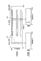
図4は、実施形態に係る診断システムの機能ブロックの構成の一例を示す図である。図5は、検知情報およびラダー信号の一例を示す図である。図6は、検知情報から抽出した特徴情報の一例を示す図である。図7は、非加工区間および加工区間の特徴情報を選択する一例を説明する図である。図8は、非加工区間および加工区間から選択した特徴情報である周波数スペクトルの一例を示す図である。図9は、加工区間らしさを算出した一例を示す図である。図10は、算出した加工区間らしさから加工区間を推定する動作を説明する図である。図4~図10を参照しながら、本実施形態に係る診断システム1および加工機200の機能ブロックの構成および動作について説明する。
(Configuration and operation of functional blocks of diagnostic system)
FIG. 4 is a diagram showing an example of the configuration of the functional block of the diagnostic system according to the embodiment. FIG. 5 is a diagram showing an example of detection information and a ladder signal. FIG. 6 is a diagram showing an example of feature information extracted from the detection information. FIG. 7 is a diagram illustrating an example of selecting feature information of a non-processed section and a processed section. FIG. 8 is a diagram showing an example of a frequency spectrum which is characteristic information selected from a non-processed section and a processed section. FIG. 9 is a diagram showing an example of calculating the uniqueness of the processing section. FIG. 10 is a diagram illustrating an operation of estimating a machining section from the calculated machining section-likeness. The configuration and operation of the functional blocks of the
図4に示すように、加工機200は、数値制御部201と、通信制御部202と、駆動制御部203と、駆動部204と、検知部211と、を有する。
As shown in FIG. 4, the
数値制御部201は、駆動部204による加工を数値制御(NC:Numerical Control)により実行する機能部である。例えば、数値制御部201は、駆動部204の動作を制御するための数値制御データを生成して出力する。また、数値制御部201は、コンテキスト情報を通信制御部202に出力する。ここで、コンテキスト情報とは、加工機200の動作の種類ごとに複数定められる情報である。コンテキスト情報は、例えば、工作機械(加工機200)の識別情報、駆動部204の識別情報(例えば、工具の識別情報等)、駆動部204に駆動される工具の径、および工具の材質等のコンフィギュレーション情報、ならびに、駆動部204に駆動される工具の動作状態、駆動部204の使用開始からの累積使用時間、駆動部204に係る負荷、駆動部204の回転数、駆動部204の加工速度等の加工条件の情報等を示す情報である。なお、これらのコンテキスト情報のうち、駆動部204に駆動される工具の動作状態を示す情報として、例えば、工具の加工対象に対する送り動作から実際の加工処理が終了するまでの区間を示すためのON/OFF信号(以下、「ラダー信号」と称する)等が含まれる。
The numerical control unit 201 is a functional unit that executes machining by the
数値制御部201は、例えば、現在の加工機200の動作に対応するコンテキスト情報を、逐次、通信制御部202を介して診断装置100に送信する。数値制御部201は、加工対象を加工する際、加工の工程に応じて、駆動する駆動部204の種類、または駆動部204の駆動状態(回転数、回転速度等)を変更する。数値制御部201は、動作の種類を変更するごとに、変更した動作の種類に対応するコンテキスト情報を、通信制御部202を介して診断装置100に逐次送信する。数値制御部201は、例えば、図2に示すCPU51で動作するプログラムによって実現される。
For example, the numerical control unit 201 sequentially transmits the context information corresponding to the operation of the
通信制御部202は、診断装置100等の外部装置との間の通信を制御する機能部である。例えば、通信制御部202は、現在の動作に対応するコンテキスト情報を診断装置100に送信する。通信制御部202は、例えば、図2に示す通信I/F54、およびCPU51で動作するプログラムによって実現される。
The
駆動制御部203は、数値制御部201により求められた数値制御データに基づいて、駆動部204を駆動制御する機能部である。駆動制御部203は、例えば、図2に示す駆動制御回路55によって実現される。
The
駆動部204は、駆動制御部203による駆動制御の対象となる機能部である。駆動部204は、駆動制御部203による制御によって工具を駆動する。駆動部204は、駆動制御部203によって駆動制御されるアクチュエータであり、例えば、図2に示すモータ56等によって実現される。なお、駆動部204は、加工に用いられ、数値制御の対象となるものであればどのようなアクチュエータであってもよい。また、駆動部204は、2以上備えられていてもよい。
The
検知部211は、加工機200に設置されたドリル、エンドミル、バイトチップもしくは砥石等の工具と加工対象とが加工動作中に接触することにより発する振動もしくは音等、または、工具もしくは加工機200自体が発する振動もしくは音等の物理量を検知し、検知した物理量の情報を検知情報(センサデータ)として診断装置100へ出力する機能部である。検知部211は、例えば、図2に示すセンサ57およびセンサアンプ58によって実現される。なお、検知部211の個数は任意である。例えば、同一の物理量を検知する複数の検知部211を備えてもよいし、相互に異なる物理量を検知する複数の検知部211を備えてもよい。例えば、加工に用いる工具である刃の折れ、および、刃のチッピング等が発生すると、加工時の音が変化する。このため、検知部211(マイク)で音響データを検知し、正常音を判断するためのモデル等を用いて判断することにより、加工機200の動作の異常を検知可能となる。
The
なお、図4に示す数値制御部201および通信制御部202は、図2に示すCPU51にプログラムを実行させること、すなわち、ソフトウェアにより実現してもよく、IC(Integrated Circuit)等のハードウェアにより実現してもよく、または、ソフトウェアおよびハードウェアを併用して実現してもよい。
The numerical control unit 201 and the
図4に示すように、診断装置100は、通信制御部101と、検知情報受信部102(第2取得部)と、加工情報取得部103(第1取得部)と、受付部104と、特徴抽出部105(抽出部)と、選択部106と、算出部107(第1算出部)と、区間判定部108(第1判定部)と、推定部109と、対象区間特定部110と、生成部111と、異常判定部112(第3判定部)と、記憶部113と、入力部114と、表示制御部115と、表示部116と、を有する。
As shown in FIG. 4, the
通信制御部101は、加工機200との間の通信を制御する機能部である。例えば、通信制御部101は、加工機200の数値制御部201から、通信制御部202を介して、コンテキスト情報を受信する。通信制御部101は、例えば、図3に示す通信I/F64、およびCPU61で動作するプログラムによって実現される。
The
検知情報受信部102は、加工機200に設置された検知部211から検知情報を受信する機能部である。検知情報受信部102は、例えば、図3に示すセンサI/F65、およびCPU61で動作するプログラムによって実現される。
The detection information receiving unit 102 is a functional unit that receives detection information from the
加工情報取得部103は、加工機200から、通信制御部101により受信されたコンテキスト情報(加工情報)を取得する機能部である。加工情報取得部103は、例えば、図3に示すCPU61で動作するプログラムによって実現される。
The processing information acquisition unit 103 is a functional unit that acquires context information (machining information) received by the
ここで、図5に、検知情報受信部102により受信された検知情報(センサデータ)、および加工情報取得部103により取得されたコンテキスト情報のうち上述のラダー信号の一例を示す。図5に示すように、検知信号は、工具が加工対象に接触する前後の非加工区間(非処理区間の一例)を示す波形部分、および、工具が加工対象に接触して実際の加工処理を行っている加工区間(処理区間の一例)を示す波形部分が含まれる。上述のように、例えば、加工機200は、工具の加工対象に対する送り動作から実際の加工処理が終了するまでの区間を示すためのON/OFF信号であるラダー信号をコンテキスト情報の一部として出力するものとする。具体的には、加工機200は、例えば、工具による加工動作の開始時にラダー信号をONにし、工具を加工対象まで送り動作をさせ、実際の加工処理が終了したときにラダー信号をOFFとする。この場合、加工機200は、工具が加工対象に接触してからラダー信号をONさせているわけではないので、図5に示すように、ラダー信号がON状態となる区間(以下、「工具送り区間」と称する場合がある)には、工具が加工対象に接触しない区間(例えば、工具を加工対象まで送り動作を行う区間)である非加工区間と、工具が加工対象に接触して加工処理を行う加工区間とが含まれることになる。さらに、この場合、工具送り区間(動作区間)ではない区間、すなわち、ラダー信号がOFF状態の区間は、非加工区間ということになる。このとき、工具送り区間に基づいて、加工区間を正確に判定することは、加工条件等によっては加工対象と工具との距離がわからない等の問題から、困難である。また、加工機200の動作の異常判定の処理(診断処理)に際し、工具送り区間に含まれる検知情報を用いる場合、非加工区間の検知情報を含むため、判定の精度が低下する等の問題が生じる。したがって、後述するように、検知情報から加工区間を精度よく推定して、推定した加工区間に含まれる検知情報(ひいてはそこから抽出される後述の特徴情報)を、診断処理に用いることが、精度の高い診断処理を行う上で重要となる。
Here, FIG. 5 shows an example of the above-mentioned ladder signal among the detection information (sensor data) received by the detection information receiving unit 102 and the context information acquired by the processing information acquisition unit 103. As shown in FIG. 5, the detection signal includes a corrugated portion indicating a non-machining section (an example of a non-processing section) before and after the tool contacts the machining target, and an actual machining process when the tool contacts the machining target. A waveform portion indicating the processing section (an example of the processing section) being performed is included. As described above, for example, the
受付部104は、通信制御部101が加工機200から受信するコンテキスト情報とは異なるコンテキスト情報の入力を受け付ける機能部である。例えば、累積使用時間は加工機200から取得するように構成できる。この場合、加工機200は、例えば、工具を交換したときに累積使用時間をリセット(初期化)する機能を備えていてもよい。
The
累積使用時間を加工機200から取得せず、受付部104が受け付けるように構成することもできる。受付部104は、例えば、キーボードおよびタッチパネル等により実現される入力部114から入力されたコンテキスト情報を受け付ける。受付部104で受け付けるコンテキスト情報は、累積使用時間に限らず、例えば、使用する工具の仕様の情報(工具の直径、刃数、材質、工具にコーティングが施されているか否か等)、加工対象の情報(材質等)の情報でもよい。また、受付部104は、外部装置からコンテキスト情報を受信するように構成してもよい。受付部104は、例えば、図3に示すCPU61で動作するプログラムによって実現される。なお、加工機200以外からコンテキスト情報を受け付ける必要がない場合は、受付部104は備えなくてもよい。
It is also possible to configure the
特徴抽出部105は、異常判定部112による判定等で用いる特徴情報を、検知情報から抽出する機能部である。特徴情報は、検知情報の特徴を示す情報であればどのような情報であってもよい。例えば、検知情報がマイクにより集音された音響データである場合、特徴抽出部105は、エネルギー、周波数スペクトル、および、MFCC(メル周波数ケプストラム係数)等を特徴情報として抽出してもよい。特徴抽出部105は、例えば、図3に示すCPU61で動作するプログラムによって実現される。
The
ここで、図6に、検知情報受信部102により受信された検知情報から、特徴抽出部105によって抽出された特徴情報の一例を示す。本実施形態では、抽出される特徴情報は、周波数スペクトルであるものとして説明する。特徴抽出部105は、例えば、検知情報に対してフレームごとにフーリエ変換を行うことによって特徴情報を抽出する。ここで、フレームとは、検知情報の所定時間(例えば、20[ms]、40[ms]等)のデータ量を示し、例えば、特徴情報が、検知情報に対してフーリエ変換することにより得られる周波数スペクトルである場合の窓長のデータ量に相当する。図6に示す特徴情報は、対応する検知情報のフレームの時間に関連付けられている。図6に示すように、加工区間の周波数スペクトルは、非加工区間の周波数スペクトルと相違する特徴を有する。ただし、図6では、非加工区間の特徴情報と加工区間の特徴情報との違いを模式的に示すため、非加工区間において周波数成分が図示されていないが、非加工区間に各周波数成分が存在しないことを示すわけではない。以下の説明では、1つの加工区間を推定するために、特徴抽出部105によって、検知情報受信部102により受信される検知情報のうち、所定範囲(例えば、ラダー信号がON状態の区間を含む区間)の検知情報から抽出された特徴情報を利用するものとする。
Here, FIG. 6 shows an example of the feature information extracted by the
選択部106は、特徴抽出部105により抽出された特徴情報から、例えば、フレームごとの特徴情報を選択する機能部である。選択部106は、例えば、図3に示すCPU61で動作するプログラムによって実現される。
The
ここで、図7に、選択部106によって、非加工区間の特徴情報において選択部分401のフレームに対応する特徴情報と、加工区間の特徴情報において選択部分402のフレームに対応する特徴情報とが選択された例を示す。非加工区間の特徴情報を選択する場合、図7に示す選択部分401のように、例えば、ラダー信号がOFF状態の区間(工具送り区間以外の区間)の特徴情報を選択するものとすればよい。一方、加工区間の特徴情報を選択する場合、図7に示す選択部分402のように、例えば、ラダー信号がON状態の区間のうち前半部分には非加工区間を含み得ることから、後半部分の特徴情報を選択するものとすればよい。
Here, in FIG. 7, the
以下の説明では、非加工区間の特徴情報を基準にして、他の部分(フレーム)で選択した特徴情報と比較するため、選択部106は、非加工区間の当該特徴情報を基準特徴情報として選択する。そして、選択部106は、上述の所定範囲(例えば、ラダー信号がON状態の区間を含む区間)において、基準特徴情報と比較するため、順次、フレーム単位で特徴情報を選択していく。なお、選択部106は、非加工区間に含まれる特徴情報に対する機械学習等によって生成された情報を基準特徴情報として選択するものとしてもよい。
In the following description, in order to compare with the feature information selected in other parts (frames) based on the feature information of the non-processed section, the
なお、選択部106による非加工区間で基準特徴情報を選択する場合、上述のように、ラダー信号がOFF状態の区間(工具送り区間以外の区間)の特徴情報を選択することに限定されるものではない。例えば、ラダー信号がONした直後の区間も非加工区間である可能性が高いことから、当該直後の区間の特徴情報を基準特徴情報として選択するものとしてもよい。また、ラダー信号の代わりに、加工機200が送信するコンテキスト情報から得られる駆動部204の回転数を用いて、実際に加工を行うための回転数となっている期間を診断装置100で判断し、その判断した結果を用いるものとしてもよい。また、非加工区間の特徴情報の選択手法として、統計的手法または機械学習等を用いて分類し選択してもよい。
When the reference feature information is selected in the non-machined section by the
また、選択部106は、基準特徴情報と比較するために、上述の所定範囲で、順次、フレーム単位で特徴情報を選択する場合、各フレームが重複することを妨げるものではない。
Further, when the
また、選択部106により選択される基準特徴情報について、例えば、過去の選択された所定回数分の基準特徴情報を平均した情報等を、後述の算出部107により使用されるものとしてもよい。これによって、選択される基準特徴情報に含み得る雑音等の影響を抑制することができる。
Further, regarding the reference feature information selected by the
また、図8に、選択部106によって選択された選択部分401のフレームに対応する特徴情報としての周波数スペクトル、および、選択部分402のフレームに対応する特徴情報としての周波数スペクトルの一例を示す。図8では、選択部分402の周波数スペクトルは、工具が加工対象に接触して加工処理を行っている加工区間での周波数スペクトルであるため、特定の周波数成分において振幅が大きい周波数スペクトルとなっている。一方、選択部分401の周波数スペクトルは、工具が加工対象に接触していない非加工区間の検知情報の振動の振幅は小さくなり、その特徴情報である周波数スペクトルに現れる振幅も小さくなっている。なお、上述のように図8は選択部分401、402それぞれの周波数スペクトルの一例であり、例えば、非加工区間の選択部分401の方が、加工区間の選択部分402よりも、周波数スペクトルに現れる振幅が小さくなる場合もあり得る。
Further, FIG. 8 shows an example of the frequency spectrum as the feature information corresponding to the frame of the
算出部107は、選択部106により選択された基準特徴情報(非加工区間の特徴情報)と、選択部106により順次選択された上述の所定範囲(例えば、ラダー信号がON状態の区間を含む区間)の特徴情報(以下、「対象特徴情報」と称する場合がある)とを比較して、それぞれの対象特徴情報の加工区間らしさ(処理区間らしさの一例)を算出する機能部である。例えば、基準特徴情報と、対象特徴情報との比較方法としては、ユークリッド距離を求めて比較する方法の他、相互相関係数またはGMM(Gaussian Mixture Model)等(機械学習の一例)を用いるものとしてもよい。算出部107は、例えば、図3に示すCPU61で動作するプログラムによって実現される。
The
ここで、図9に、算出部107が、基準特徴情報と、各対象特徴情報とのユークリッド距離を求めて正規化した値を加工区間らしさとして算出した例を示す。図9においては、加工区間らしさが「1」に近いほど、加工区間の尤もらしさが高いことを示す。なお、加工区間らしさは、雑音を含む検知情報から抽出された特徴情報から算出されるので、図9に示すように、ばらつきを含む値となる。
Here, FIG. 9 shows an example in which the
なお、選択部106により非加工区間で特徴情報を基準特徴情報として選択され、算出部107によりその基準特徴情報との比較で各対象特徴情報の加工区間らしさが算出されるものとしたが、これに限定されるものではない。すなわち、選択部106により加工区間の特徴情報を基準特徴情報として選択され、算出部107により加工区間らしさが算出されるものとしてもよい。また、この場合、加工区間らしさではなく、非加工区間らしさを算出するものとしてもよい。ただし、非加工区間らしさを示す値は、加工区間らしさの裏返しを示す値である。
The
区間判定部108は、算出部107により算出された加工区間らしさに対して閾値判定を行う機能部である。区間判定部108は、例えば、図3に示すCPU61で動作するプログラムによって実現される。
The
推定部109は、区間判定部108によって加工区間らしさが所定の閾値よりも大きいと判定された区間を、加工区間として推定する機能部である。推定部109は、例えば、図3に示すCPU61で動作するプログラムによって実現される。
The
ここで、図10に、算出部107により算出された加工区間らしさに対して、区間判定部108により閾値判定がなされ、推定部109により加工区間が推定された例を示す。図10に示すように、加工区間らしさが所定の閾値よりも大きい「推定される加工区間」が加工区間として推定されることになる。逆に、加工区間らしさが閾値よりも小さい区間を非加工区間として推定することができる。このように、推定部109により推定された加工区間に含まれる検知情報(特徴情報)を診断処理に用いることによって、精度の高い診断処理を行うことができる。
Here, FIG. 10 shows an example in which a threshold value is determined by the
なお、加工区間を推定するために、区間判定部108は、加工区間らしさに対して閾値判定を行うものとしているが、これに限定されるものではなく、例えば、統計的な手法を用いて、加工区間らしさに対して判定を行うものとしてもよい。
In addition, in order to estimate the processing section, the
対象区間特定部110は、特徴抽出部105により抽出された特徴情報のうち、推定部109により推定された加工区間に対応する特徴情報を特定する機能部である。対象区間特定部110は、例えば、図3に示すCPU61で動作するプログラムによって実現される。
The target section specifying unit 110 is a functional unit that specifies the feature information corresponding to the processing section estimated by the
生成部111は、加工機200の正常動作時に検知情報から特徴抽出部105により抽出された特徴情報を用いた学習により、加工情報取得部103により取得されたコンテキスト情報に対応する、加工が正常に行われたことを判断するためのモデルを生成する機能部である。なお、モデルを外部装置で生成する場合は、生成部111は備えられなくてもよい。また、生成部111は、モデルが定められていないコンテキスト情報と、当該コンテキスト情報に対応する検知情報とが入力された場合に、この検知情報から抽出された特徴情報を用いて、当該コンテキスト情報に対応するモデルを生成してもよい。生成部111は、例えば、図3に示すCPU61で動作するプログラムによって実現される。
The
異常判定部112は、特徴抽出部105により抽出された特徴情報と、加工情報取得部103により取得されたコンテキスト情報に対応するモデルと、を用いて、加工機200の動作が正常であるか否かを判定する機能部である。異常判定部112は、検知情報から抽出された特徴情報が正常であることの尤もらしさを示す尤度を、対応するモデルを用いて算出する。異常判定部112は、尤度と、予め定められた閾値とを比較し、例えば、尤度が閾値以上である場合に、加工機200の動作は正常であると判定する。また、異常判定部112は、尤度が閾値未満である場合に、加工機200の動作は異常であると判定する。異常判定部112は、例えば、図3に示すCPU61で動作するプログラムによって実現される。
The
記憶部113は、生成部111により生成されたモデルをコンテキスト情報と関連付けて記憶する機能部である。また、記憶部113は、検知情報受信部102により受信された検知情報を、加工情報取得部103により受信されたコンテキスト情報と関連付けて記憶するものとしてもよい。記憶部113は、例えば、図3のRAM63および補助記憶装置66等によって実現される。
The
入力部114は、文字および数字等の入力、各種指示の選択、ならびにカーソルの移動等の操作を行うための機能部である。入力部114は、図3に示す入力装置67によって実現される。
The
表示制御部115は、表示部116の表示動作を制御する機能部である。具体的には、表示制御部115は、例えば、異常判定部112による異常判定の結果等を、表示部116に表示させる。表示制御部115は、例えば、図3に示すCPU61で動作するプログラムによって実現される。
The
表示部116は、表示制御部115による制御に従って各種情報を表示する機能部である。表示部116は、例えば、図3に示すディスプレイ68によって実現される。
The
なお、図4に示した診断装置100の各機能部(通信制御部101、検知情報受信部102、加工情報取得部103、受付部104、特徴抽出部105、選択部106、算出部107、区間判定部108、推定部109、対象区間特定部110、生成部111、異常判定部112および表示制御部115)は、図3のCPU61にプログラムを実行させること、すなわち、ソフトウェアにより実現してもよく、IC等のハードウェアにより実現してもよく、または、ソフトウェアおよびハードウェアを併用して実現してもよい。
Each functional unit of the
また、図4に示した診断装置100および加工機200それぞれの各機能部は、機能を概念的に示したものであって、このような構成に限定されるものではない。例えば、図4で独立した機能部として図示した複数の機能部を、1つの機能部として構成してもよい。一方、図4の1つの機能部が有する機能を複数に分割し、複数の機能部として構成するものとしてもよい。
Further, each functional unit of the
(診断装置による加工区間推定処理)
図11は、実施形態における加工区間推定処理の一例を示すフローチャートである。図11を参照しながら、本実施形態に係る診断システム1の診断装置100の加工区間推定処理の流れについて説明する。
(Processing section estimation processing by diagnostic equipment)
FIG. 11 is a flowchart showing an example of the processing section estimation process in the embodiment. The flow of the processing section estimation process of the
<ステップS101>
加工機200の数値制御部201は、稼動中の加工機200の動作の示すコンテキスト情報(ラダー信号を含む)を、逐次、診断装置100に送信する。診断装置100の通信制御部101は、このようにして加工機200から送信されたコンテキスト情報を受信する。診断装置100の加工情報取得部103は、通信制御部101により受信されたコンテキスト情報を取得する。そして、ステップS102へ移行する。
<Step S101>
The numerical control unit 201 of the
<ステップS102>
加工機200の検知部211は、検知情報を、逐次、出力する。診断装置100の検知情報受信部102は、このようにして加工機200から送信された検知情報(センサデータ)を受信する。そして、ステップS103へ移行する。
<Step S102>
The
<ステップS103>
診断装置100の特徴抽出部105は、受信された検知情報から特徴情報を抽出する。特徴抽出部105は、例えば、所定範囲(例えば、ラダー信号がON状態の区間を含む区間)の検知情報に対してフレームごとにフーリエ変換を行うことによって特徴情報を抽出する。そして、ステップS104へ移行する。
<Step S103>
The
<ステップS104>
診断装置100の選択部106は、特徴抽出部105により抽出された特徴情報から、フレームごとの特徴情報を選択する。具体的には、選択部106は、非加工区間の当該特徴情報を基準特徴情報として選択する。そして、ステップS105へ移行する。
<Step S104>
The
<ステップS105>
選択部106は、所定範囲(例えば、ラダー信号がON状態の区間を含む区間)において、基準特徴情報と比較するため、順次、フレーム単位で特徴情報(対象特徴情報)を選択していく。そして、診断装置100の算出部107は、選択部106により選択された基準特徴情報(非加工区間の特徴情報)と、選択部106により順次選択された上述の所定範囲の対象特徴情報とを比較して、それぞれの対象特徴情報の加工区間らしさを算出する。そして、ステップS106へ移行する。
<Step S105>
The
<ステップS106>
診断装置100の区間判定部108は、算出部107により算出された加工区間らしさに対して閾値判定を行い、加工区間らしさが所定の閾値よりも大きい判定した区間を加工区間と判定し、加工区間らしさが所定の閾値よりも小さいと判定した区間を非加工区間と判定する。そして、ステップS107へ移行する。
<Step S106>
The
<ステップS107>
診断装置100の推定部109は、区間判定部108によって加工区間らしさが所定の閾値よりも大きいと判定された区間を、加工区間として推定する。
<Step S107>
The
以上のステップS101~S107によって、加工区間推定処理が実行される。 The machining section estimation process is executed by the above steps S101 to S107.
(診断装置による診断処理)
図12は、実施形態における診断処理の一例を示すフローチャートである。図12を参照しながら、本実施形態に係る診断システム1の診断装置100の診断処理の流れについて説明する。
(Diagnosis processing by diagnostic equipment)
FIG. 12 is a flowchart showing an example of the diagnostic process in the embodiment. The flow of the diagnostic process of the
上述のように、加工機200の数値制御部201は、現在の加工機200の動作を示すコンテキスト情報を、逐次、診断装置100に送信する。診断装置100の通信制御部101は、このようにして加工機200から送信されたコンテキスト情報を受信する(ステップS201)。そして、診断装置100の加工情報取得部103は、通信制御部101により受信されたコンテキスト情報を取得する。
As described above, the numerical control unit 201 of the
また、加工機200の検知部211は、検知情報を、逐次、出力する。診断装置100の検知情報受信部102は、このようにして加工機200から送信された検知情報(センサデータ)を受信する(ステップS202)。
Further, the
診断装置100の特徴抽出部105は、受信された検知情報から特徴情報を抽出する(ステップS203)。ただし、ここでは、診断装置100の対象区間特定部110が、加工区間推定処理において特徴抽出部105により抽出された特徴情報のうち、推定部109により推定された加工区間に対応する特徴情報を特定するものとすればよい。
The
診断装置100の異常判定部112は、加工情報取得部103により取得されたコンテキスト情報に対応するモデルを記憶部113から取得する(ステップS204)。
The
異常判定部112は、特定された特徴情報と、取得されたコンテキスト情報に対応するモデルとを用いて、加工機200が正常に動作しているか否かを判定する(ステップS205)。
The
異常判定部112は、判定結果を出力する(ステップS206)。判定結果の出力方法はどのような方法であってもよい。異常判定部112は、例えば、診断装置100の表示制御部115に対して、判定結果を表示部116に表示させるものとしてもよい。または、異常判定部112が、サーバ装置およびPC(Personal Computer)等の外部装置に判定結果を出力するものとしてもよい。
The
以上のステップS201~S206によって、診断処理が実行される。 The diagnostic process is executed by the above steps S201 to S206.
(診断装置によるモデル生成処理)
図13は、実施形態におけるモデル生成処理の一例を示すフローチャートである。図13を参照しながら、本実施形態に係る診断システム1の診断装置100のモデル生成処理の流れについて説明する。なお、モデル生成処理は、例えば、診断処理の前に事前に実行される。または、モデルが定められていないコンテキスト情報が入力された場合にモデル生成処理を実行するように構成してもよい。
(Model generation processing by diagnostic equipment)
FIG. 13 is a flowchart showing an example of the model generation process in the embodiment. The flow of the model generation process of the
診断装置100の通信制御部101は、加工機200から送信されたコンテキスト情報を受信する(ステップS301)。そして、診断装置100の加工情報取得部103は、通信制御部101により受信されたコンテキスト情報を取得する。
The
診断装置100の検知情報受信部102は、加工機200から送信された検知情報(センサデータ)を受信する(ステップS302)。
The detection information receiving unit 102 of the
このように受信されたコンテキスト情報および検知情報が、モデルの生成に利用される。モデルは、コンテキスト情報ごとに生成されるため、検知情報は、対応するコンテキスト情報に関連付けられる必要がある。このため、例えば、検知情報受信部102は、受信した検知情報を、同じタイミングで通信制御部101により受信されたコンテキスト情報と対応付けて記憶部113等に記憶させる。各情報を記憶部113等に一旦記憶し、正常時の情報であることを確認し、正常時の情報のみを用いてモデルを生成してもよい。すなわち、正常であるとラベルづけされた検知情報を用いてモデルを生成してもよい。
The context information and detection information received in this way are used to generate the model. Since the model is generated for each context information, the detection information needs to be associated with the corresponding context information. Therefore, for example, the detection information receiving unit 102 stores the received detection information in the
正常であるか否かの確認(ラベルづけ)は、情報を記憶部113等に記憶した後の任意のタイミングで実行してもよいし、加工機200を動作させながらリアルタイムに実行してもよい。ラベルづけを実行せず、情報が正常であると仮定してモデルを生成してもよい。正常であると仮定した情報が実際は異常であった情報であった場合は、生成されたモデルにより正しく判定処理が実行されなくなる。異常と判定される頻度等によりこのような状況であるかを判断でき、誤って生成されたモデルを削除する等の対応を取ることができる。また、異常であった情報から生成されたモデルを、異常であることを判定するモデルとして利用してもよい。
The confirmation (labeling) of whether or not the information is normal may be executed at an arbitrary timing after the information is stored in the
診断装置100の特徴抽出部105は、検知情報受信部102により受信された検知情報から特徴情報を抽出する(ステップS303)。なお、特徴抽出部105は、加工区間推定処理において、推定部109により推定された加工区間に基づいて、特徴情報を抽出するものとしてもよい。
The
診断装置100の生成部111は、特徴抽出部105により抽出された特徴情報から、加工情報取得部103により取得されたコンテキスト情報に対応するモデルを生成する(ステップS304)。生成部111は、生成したモデルを、例えば、コンテキスト情報および特徴情報との関連付けを行い、記憶部113に記憶させる(ステップS305)。
The
以上のステップS301~S305によって、モデル生成処理が実行される。 The model generation process is executed by the above steps S301 to S305.
(モデル生成処理および診断処理の具体例)
次に、本実施形態によるモデル生成処理および診断処理の具体例について説明する。図14は、実施形態におけるモデル生成処理および診断処理の具体例を説明する図である。
(Specific examples of model generation processing and diagnostic processing)
Next, specific examples of the model generation process and the diagnostic process according to the present embodiment will be described. FIG. 14 is a diagram illustrating a specific example of the model generation process and the diagnostic process in the embodiment.
図14は、例えば、ある部品を加工する工程の一部についてのモデル生成処理、および、診断処理を示す。モデル生成処理では、コンテキスト情報701と共に受信された複数の検知情報(図14では検知情報711a~711c)が利用される。なお、検知情報の個数は3に限られるものではなく、任意の個数とすることができる。
FIG. 14 shows, for example, a model generation process and a diagnostic process for a part of a process of processing a certain part. In the model generation process, a plurality of detection information (
コンテキスト情報701は、加工工程が、4つのモータ(モータA、モータB、モータC、モータD)を駆動する動作を含むことを示している。特徴抽出部105は、検知情報受信部102により受信された検知情報から特徴情報を抽出する。なお、特徴抽出部105は、加工区間推定処理において、推定部109により推定された加工区間に基づいて、特徴情報を抽出するものとしてもよい。生成部111は、各モータに対応するコンテキスト情報ごとに、対応する検知情報から抽出された特徴情報を用いてモデルを生成する。生成されたモデルは、対応するコンテキスト情報と対応付けられて記憶部113等に記憶される。図14では、モータBが駆動される場合のコンテキスト情報に対して生成されたモデル(「モータB」)が記憶部113に記憶された例が示されている。記憶されたモデルは、その後の診断処理で参照される。なお、ここではコンテキスト情報としてモータの種類のみで説明したが、それ以外の必要なコンテキスト情報、例えば、各モータによって駆動される工具の種類等を示すコンテキスト情報についても、当然対応付けてモデルは記憶される。
The
加工区間推定処理および診断処理では、モデル生成処理と同様に、コンテキスト情報701と共に、検知情報721が受信される。コンテキスト情報が「モータBが駆動されていること」を示す場合、当該コンテキスト情報701に含まれるラダー信号に基づいて、上述の加工区間推定処理によって、受信された検知情報に対して加工区間が推定される。コンテキスト情報が「モータBが駆動されていること」を示す場合、異常判定部112は、例えば、このコンテキスト情報が受信された期間に受信された検知情報のうち、推定された加工区間の検知情報と、記憶部113に記憶されているモデル「モータB」とを用いて、加工機200の動作が正常であるか否かを判定する。
In the processing section estimation process and the diagnostic process, the
他のコンテキスト情報が受信される場合も同様に、対応する検知情報のうち推定された加工区間の検知情報と、対応するモデルとを用いて、異常判定部112による判定が実行される。
Similarly, when other context information is received, the
これにより、異常の判定に有効な検知情報のみを用いて診断処理を実行することができる。不要な区間を判定対象から外すことによって、誤判定を減らすこと、および、計算コストを減らすことが可能となる。すなわち、診断処理の高精度化および効率化が実現可能となる。 As a result, the diagnostic process can be executed using only the detection information that is effective for determining the abnormality. By excluding unnecessary sections from the judgment target, it is possible to reduce erroneous judgments and reduce calculation costs. That is, it is possible to improve the accuracy and efficiency of the diagnostic process.
また、相互に異なる加工工程であっても、例えば、同一のモータ等を示す同一のコンテキスト情報を使用する場合は、対応するモデルを共通に利用して診断処理を実行してもよい。図15は、共通のモデルを他の加工工程で使用する例を説明する図である。 Further, even if the processing processes are different from each other, for example, when the same context information indicating the same motor or the like is used, the corresponding model may be commonly used to execute the diagnostic process. FIG. 15 is a diagram illustrating an example in which a common model is used in other processing processes.
図15のコンテキスト情報901は、加工工程が、4つのモータ(モータX、モータY、モータZ、モータB)を駆動する動作を含むことを示している。モータBを使用する点は、例えば、図14に示す加工工程と共通する。このため、図15の加工工程でも、異常判定部112は、記憶部113に記憶されている同一のモデル「モータB」と、検知情報921のうち、推定された加工区間の検知情報とを用いて診断処理を実行できる。
The
また、図16は、モデルが生成されていないコンテキスト情報が入力された場合にモデルを生成する動作を説明する図である。図16のコンテキスト情報1101は、加工工程が、4つのモータ(モータX、モータC、モータD、モータB)を駆動する動作を含むことを示している。モータXの駆動を示すコンテキスト情報に対して、モデルが生成されていないものとする。
Further, FIG. 16 is a diagram illustrating an operation of generating a model when context information for which a model has not been generated is input. The
この場合、特徴抽出部105は、複数の検知情報(図16では、検知情報1111a、1111b、1111c)それぞれについて、「モータXが駆動されていること」を示すコンテキスト情報に対応する期間の検知情報から特徴情報を抽出する。生成部111は、抽出された特徴情報のうち、推定部109により推定された加工区間に対応する特徴情報を用いて、「モータXが駆動されていること」を示すコンテキスト情報に対応するモデル「モータX」を生成し、記憶部113に記憶する。これにより、今後モータXを駆動する期間についても異常の判定が可能となる。
In this case, the
このように、現在の動作を示すコンテキスト情報を加工機200から受信し、受信したコンテキスト情報に対応するモデルを用いて異常を判定できる。したがって、動作する駆動部を高精度に特定し、異常をより高精度に診断可能となる。
In this way, the context information indicating the current operation is received from the
以上のように、本実施形態に係る診断システム1では、加工機200から受信した検知情報に対して特徴情報を抽出し、基準となる特徴情報と、他の部分の特徴情報との比較から加工区間らしさを算出し、加工区間らしさに基づいて加工区間を推定するものとしている。これによって、加工機200等の対象装置の動作の異常を判定するための検知情報における実際の加工区間を精度よく推定することができる。したがって、このように推定された加工区間における特徴情報を用いて対象装置の動作の診断を行うので、精度の高い診断処理が可能となる。さらに、推定された加工区間における特徴情報を用いてモデルを生成することによって、さらに精度の高い診断処理が可能となる。
As described above, in the
(変形例1)
本変形例では、推定された加工区間の長さに基づいて、工具が折損したか否かを判定する動作について説明する。なお、本変形例に係る診断システムの全体構成、ならびに、診断装置(後述する診断装置100a)および加工機200のハードウェア構成は、上述の実施形態で説明した構成と同様である。
(Modification 1)
In this modification, an operation of determining whether or not the tool is broken will be described based on the estimated length of the machining section. The overall configuration of the diagnostic system according to this modification, and the hardware configuration of the diagnostic device (diagnosis device 100a described later) and the
図17は、変形例1に係る診断システムの機能ブロックの構成の一例を示す図である。図18は、工具の折損を検出する動作の一例を示す図である。図17および図18を参照しながら、本変形例に係る診断システム1aの機能ブロックの構成および動作について説明する。なお、加工機200の機能ブロックの構成は、上述の実施形態で説明した構成と同様である。
FIG. 17 is a diagram showing an example of the configuration of the functional block of the diagnostic system according to the first modification. FIG. 18 is a diagram showing an example of an operation for detecting breakage of a tool. The configuration and operation of the functional block of the diagnostic system 1a according to the present modification will be described with reference to FIGS. 17 and 18. The configuration of the functional block of the
図17に示すように、本変形例の診断システム1aの診断装置100aは、通信制御部101と、検知情報受信部102(第2取得部)と、加工情報取得部103(第1取得部)と、受付部104と、特徴抽出部105(抽出部)と、選択部106と、算出部107(第1算出部)と、区間判定部108(第1判定部)と、推定部109と、対象区間特定部110と、生成部111と、異常判定部112(第3判定部)と、記憶部113と、入力部114と、表示制御部115と、表示部116と、折損判定部117(第2判定部)と、を有する。なお、診断装置100aが有する機能部のうち折損判定部117以外の機能部の動作は、上述の実施形態で説明した動作と同様である。
As shown in FIG. 17, the diagnostic device 100a of the diagnostic system 1a of this modification has a
折損判定部117は、コンテキスト情報に対応付けて予め求めておいた正常の加工区間の長さ(以下、「通常の加工区間長」と称する)と、推定部109により推定された加工区間とを比較することによって、工具が折損したか否かを判定する機能部である。工具による加工動作中に、工具が折損した場合、その後の加工処理では工具が加工対象に接触しなくなるので、この場合の検知情報に基づいて、推定部109により推定された加工区間の長さは、図18に示すように、通常の加工区間長よりも短くなることが見込まれる。この場合、例えば、折損判定部117は、推定部109により推定された加工区間の長さが、通常の加工区間長と比較して所定の長さ以上短い場合、工具が折損したと判定するものとすればよい。また、折損判定部117は、工具が折損したと判定した場合、例えば、診断装置100aの表示制御部115に対して、判定結果を表示部116に表示させるものとしてもよく、または、サーバ装置およびPC等の外部装置に判定結果を出力するものとしてもよい。折損判定部117は、例えば、図3に示すCPU61で動作するプログラムによって実現される。なお、図17に示した診断装置100aの折損判定部117は、図3のCPU61にプログラムを実行させること、すなわち、ソフトウェアにより実現してもよく、IC等のハードウェアにより実現してもよく、または、ソフトウェアおよびハードウェアを併用して実現してもよい。
The
なお、通常の加工区間長(所定区間の長さの一例)は、例えば、過去に推定された正常な加工区間の長さの平均値としてもよく、または、前回、推定部109により推定された加工区間の長さとしてもよい。
The normal machining section length (an example of the length of the predetermined section) may be, for example, the average value of the lengths of the normal machining sections estimated in the past, or was estimated by the
また、折損判定部117は、通常の加工区間長と、推定部109により推定された加工区間の長さとを比較するものとしたが、これに限定されるものではない。例えば、上述のように加工区間と非加工区間とを含む工具送り区間(所定区間の一例)と、推定部109により推定された加工区間の長さとを比較して、工具の折損の有無を判定するものとしてもよい。
Further, the
また、折損判定部117は、工具の折損を判定するとしたが、これに限定されるものではなく、工具の変形、欠損、折損または治具からの欠落等の工具の異常を広く判定するものとしてもよい。
Further, the
以上のように、加工区間を推定することによって、正常の加工区間の長さ(通常の加工区間長)との比較により、工具の折損の有無を判定することができる。これによって、例えば、工具の折損をユーザに通知して工具の交換を促すことが可能となり、加工機200のダウンタイムを短縮することができる。
As described above, by estimating the machining section, it is possible to determine the presence or absence of breakage of the tool by comparing with the length of the normal machining section (normal machining section length). As a result, for example, it is possible to notify the user of the breakage of the tool and prompt the user to replace the tool, and the downtime of the
(変形例2)
本変形例では、検知情報から抽出される特徴情報の変化から、工具の折損の予兆を提示する動作について説明する。なお、本変形例に係る診断システムの全体構成、ならびに、診断装置(後述する診断装置100b)および加工機200のハードウェア構成は、上述の実施形態で説明した構成と同様である。
(Modification 2)
In this modification, the operation of presenting a sign of tool breakage from the change of the feature information extracted from the detection information will be described. The overall configuration of the diagnostic system according to this modification, and the hardware configuration of the diagnostic device (diagnosis device 100b described later) and the
図19は、変形例2に係る診断システムの機能ブロックの構成の一例を示す図である。図20は、工具の劣化に伴う周波数スペクトルの変化の一例を説明する図である。図21は、折損予兆スコアの一例を示す図である。図19~図21を参照しながら、本変形例に係る診断システム1bの機能ブロックの構成および動作について説明する。なお、加工機200の機能ブロックの構成は、上述の実施形態で説明した構成と同様である。
FIG. 19 is a diagram showing an example of the configuration of the functional block of the diagnostic system according to the modified example 2. FIG. 20 is a diagram illustrating an example of a change in the frequency spectrum due to deterioration of the tool. FIG. 21 is a diagram showing an example of a breakage sign score. The configuration and operation of the functional block of the diagnostic system 1b according to the present modification will be described with reference to FIGS. 19 to 21. The configuration of the functional block of the
図19に示すように、本変形例の診断システム1bの診断装置100bは、通信制御部101と、検知情報受信部102(第2取得部)と、加工情報取得部103(第1取得部)と、受付部104と、特徴抽出部105(抽出部)と、選択部106と、算出部107(第1算出部)と、区間判定部108(第1判定部)と、推定部109と、対象区間特定部110と、生成部111と、異常判定部112(第3判定部)と、記憶部113と、入力部114と、表示制御部115と、表示部116と、スコア算出部118(第2算出部)と、を有する。なお、診断装置100bが有する機能部のうちスコア算出部118以外の機能部の動作は、上述の実施形態で説明した動作と同様である。
As shown in FIG. 19, the diagnostic device 100b of the diagnostic system 1b of this modified example includes a
スコア算出部118は、予め求めておいた新品の状態の工具について推定された加工区間の特徴情報と、その後、推定部109により推定された加工区間に対応する特徴情報とから、特徴情報の変化を示すスコアを算出する機能部である。
The score calculation unit 118 changes the characteristic information from the characteristic information of the machining section estimated for the tool in a new state obtained in advance and the feature information corresponding to the machining section estimated by the
加工区間の特徴情報(周波数スペクトル)は、例えば、上述の図6に示した特徴情報(周波数スペクトル)が新品の状態の工具に対応するものとすると、図20に示すように、工具の摩耗等による劣化によって変化する。一般に、ドリル等の工具は、劣化によって加工対象との摩擦が大きくなり、新品時の周波数成分と同じ周波数成分の振幅が大きくなったり、または、新品時の周波数スペクトルでは出現していなかった周波数成分が生じたりする。そのため、上述の図8に示したような周波数スペクトルを積分した値(周波数スペクトルの面積)は、工具が新品時よりも、工具が劣化した時の方が大きくなるものと想定される。 Assuming that the feature information (frequency spectrum) of the machined section corresponds to the tool in a new state, for example, assuming that the feature information (frequency spectrum) shown in FIG. 6 described above corresponds to a tool in a new state, as shown in FIG. It changes due to deterioration due to. In general, tools such as drills have a large friction with the object to be machined due to deterioration, and the amplitude of the same frequency component as the frequency component at the time of new product becomes large, or the frequency component that does not appear in the frequency spectrum at the time of new product. Occurs. Therefore, it is assumed that the integrated value (frequency spectrum area) of the frequency spectrum as shown in FIG. 8 described above is larger when the tool is deteriorated than when the tool is new.
そこで、スコア算出部118は、例えば、推定部109により推定された加工区間に対応する特徴情報に関する値(例えば、周波数スペクトルの積分値)を積算した値を、特徴情報の変化を示すスコア(折損予兆スコア)として算出し、図21に示すように、加工時間に対応するスコアをプロットしたグラフを生成し、表示制御部115に対して、当該グラフを表示部116に表示させる。これによって、加工機200のユーザは、例えば、折損予兆スコアが図21に示すように急峻に上昇した場合、工具の折損の予兆を認識することができる。スコア算出部118は、例えば、図3に示すCPU61で動作するプログラムによって実現される。なお、図19に示した診断装置100bのスコア算出部118は、図3のCPU61にプログラムを実行させること、すなわち、ソフトウェアにより実現してもよく、IC等のハードウェアにより実現してもよく、または、ソフトウェアおよびハードウェアを併用して実現してもよい。
Therefore, for example, the score calculation unit 118 integrates the values related to the feature information corresponding to the processing section estimated by the estimation unit 109 (for example, the integrated value of the frequency spectrum) into the score indicating the change in the feature information (breakage). It is calculated as a sign score), and as shown in FIG. 21, a graph in which the score corresponding to the machining time is plotted is generated, and the
なお、上述のように、スコア算出部118は、推定部109により推定された加工区間に対応する特徴情報に関する値(例えば、周波数スペクトルの積分値)を積算した値をスコアとして算出し、プロットするものとしたが、特徴情報に関する値そのものをプロットするものとしてもよい。 As described above, the score calculation unit 118 calculates and plots the value obtained by integrating the values related to the feature information corresponding to the processing section estimated by the estimation unit 109 (for example, the integrated value of the frequency spectrum) as the score. However, the value itself related to the feature information may be plotted.
以上のように、推定部109により推定された加工区間に対応する特徴情報に関する値(例えば、周波数スペクトルの積分値)の変化から、工具の折損の予兆を認識することができる。この場合、推定部109により図20に示す非加工区間に存在する加工処理と関連のない雑音成分について除かれた加工区間のみに対応する特徴情報に関する値の変化をとらえているので、工具の折損の予兆を精度よく提示することができる。
As described above, the sign of tool breakage can be recognized from the change in the value (for example, the integrated value of the frequency spectrum) related to the feature information corresponding to the machining section estimated by the
なお、上述の実施形態および各変形例の診断システムで実行されるプログラムは、ROM等に予め組み込まれて提供するように構成してもよい。 The program executed by the above-described embodiment and the diagnostic system of each modification may be configured to be provided by being incorporated in a ROM or the like in advance.
また、上述の実施形態および各変形例の診断システムで実行されるプログラムは、インストール可能な形式又は実行可能な形式のファイルでCD-ROM(Compact Disc Read Only Memory)、フレキシブルディスク(FD)、CD-R(Compact Disk-Recordable)、DVD(Digital Versatile Disk)等のコンピュータで読み取り可能な記録媒体に記録してコンピュータ・プログラム・プロダクトとして提供するように構成してもよい。 Further, the program executed by the diagnostic system of the above-described embodiment and each modification is a CD-ROM (Computer Disc Read Only Memory), a flexible disk (FD), or a CD in an installable format or an executable format file. -R (Compact Disk-Recordable), DVD (Digital Versaille Disk), or the like may be configured to be recorded on a computer-readable recording medium and provided as a computer program product.
また、上述の実施形態および各変形例の診断システムで実行されるプログラムを、インターネット等のネットワークに接続されたコンピュータ上に格納し、ネットワーク経由でダウンロードさせることにより提供するように構成してもよい。また、上述の実施形態および各変形例の診断システムで実行されるプログラムをインターネット等のネットワーク経由で提供または配布するように構成してもよい。 Further, the program executed by the diagnostic system of the above-described embodiment and each modification may be stored on a computer connected to a network such as the Internet and provided by downloading via the network. .. Further, the program executed by the above-described embodiment and the diagnostic system of each modification may be provided or distributed via a network such as the Internet.
また、上述の実施形態および各変形例の診断システムで実行されるプログラムは、上述した各機能部を含むモジュール構成となっており、実際のハードウェアとしてはCPU(プロセッサ)がROMからプログラムを読み出して実行することにより上述の各機能部が主記憶装置上にロードされ、各機能部が主記憶装置上に生成されるようになっている。 Further, the program executed in the above-described embodiment and the diagnostic system of each modification has a module configuration including each of the above-mentioned functional units, and as actual hardware, the CPU (processor) reads the program from the ROM. Each of the above-mentioned functional units is loaded on the main storage device, and each functional unit is generated on the main storage device.
1、1a、1b 診断システム
51 CPU
52 ROM
53 RAM
54 通信I/F
55 駆動制御回路
56 モータ
57 センサ
58 センサアンプ
59 バス
61 CPU
62 ROM
63 RAM
64 通信I/F
65 センサI/F
66 補助記憶装置
67 入力装置
68 ディスプレイ
69 バス
100、100a、100b 診断装置
101 通信制御部
102 検知情報受信部
103 加工情報取得部
104 受付部
105 特徴抽出部
106 選択部
107 算出部
108 区間判定部
109 推定部
110 対象区間特定部
111 生成部
112 異常判定部
113 記憶部
114 入力部
115 表示制御部
116 表示部
117 折損判定部
118 スコア算出部
200 加工機
201 数値制御部
202 通信制御部
203 駆動制御部
204 駆動部
211 検知部
401、402 選択部分
701、701-2 コンテキスト情報
711a~711c 検知情報
721 検知情報
901 コンテキスト情報
921 検知情報
1101 コンテキスト情報
1111a~1111c 検知情報
1,1a, 1b
52 ROM
53 RAM
54 Communication I / F
55 Drive control circuit 56
62 ROM
63 RAM
64 Communication I / F
65 Sensor I / F
66
Claims (18)
前記対象装置の動作に応じて変化する物理量を検知する検知部から出力される検知情報を取得する第2取得部と、
前記第2取得部により取得された前記検知情報から、前記コンテキスト情報が示す前記対象装置の特定の動作区間、を含む区間の該検知情報のフレーム毎の特徴を示す複数の特徴情報を時系列で抽出する抽出部と、
前記特徴情報に基づいて、基準となる基準特徴情報を選択し、前記基準特徴情報と比較するための対象特徴情報を順次選択する選択部と、
前記選択部により選択された前記基準特徴情報と、前記各対象特徴情報との比較から、前記各フレームに対応する区間の前記対象装置の特定の処理の処理区間らしさを算出する第1算出部と、
前記処理区間らしさに基づいて、該処理区間らしさに対応する前記対象特徴情報が前記特定の処理の処理区間に含まれるか否かを判定する第1判定部と、
前記第1判定部の判定結果に基づいて、前記動作区間における前記処理区間を推定する推定部と、
を備えた診断装置。 A first acquisition unit that acquires context information corresponding to an operating operation from a plurality of context information determined based on the type of operation of the target device from the target device.
A second acquisition unit that acquires detection information output from a detection unit that detects a physical quantity that changes according to the operation of the target device, and a second acquisition unit.
From the detection information acquired by the second acquisition unit, a plurality of feature information indicating the characteristics of each frame of the detection information in the section including the specific operation section of the target device indicated by the context information is displayed in chronological order. Extraction unit to extract and
A selection unit that selects reference reference feature information based on the feature information and sequentially selects target feature information for comparison with the reference feature information.
A first calculation unit that calculates the processing section-likeness of a specific process of the target device in the section corresponding to each frame from the comparison between the reference feature information selected by the selection unit and each target feature information. ,
A first determination unit that determines whether or not the target feature information corresponding to the processing section characteristic is included in the processing section of the specific processing, based on the processing section characteristic.
An estimation unit that estimates the processing section in the operation section based on the determination result of the first determination unit, and an estimation unit.
Diagnostic device equipped with.
前記第1算出部は、前記基準特徴情報としての周波数スペクトルと、前記各対象特徴情報としての周波数スペクトルとの差異に基づいて、前記処理区間らしさを算出する請求項1~4のいずれか一項に記載の診断装置。 The extraction unit extracts the frequency spectrum for each frame of the detection information in the section including the operation section as the feature information.
The first calculation unit is any one of claims 1 to 4 for calculating the uniqueness of the processing section based on the difference between the frequency spectrum as the reference feature information and the frequency spectrum as each target feature information. The diagnostic device described in.
請求項1~15のいずれか一項に記載の診断装置と、
を有する診断システム。 With the detector
The diagnostic device according to any one of claims 1 to 15, and the diagnostic apparatus.
Diagnostic system with.
前記対象装置の動作に応じて変化する物理量を検知する検知部から出力される検知情報を取得する第2取得ステップと、
取得した前記検知情報から、前記コンテキスト情報が示す前記対象装置の特定の動作区間、を含む区間の該検知情報のフレーム毎の特徴を示す複数の特徴情報を時系列で抽出する抽出ステップと、
前記特徴情報に基づいて、基準となる基準特徴情報を選択し、前記基準特徴情報と比較するための対象特徴情報を順次選択する選択ステップと、
選択した前記基準特徴情報と、前記各対象特徴情報との比較から、前記各フレームに対応する区間の前記対象装置の特定の処理の処理区間らしさを算出する算出ステップと、
前記処理区間らしさに基づいて、該処理区間らしさに対応する前記対象特徴情報が前記特定の処理の処理区間に含まれるか否かを判定する判定ステップと、
判定結果に基づいて、前記動作区間における前記処理区間を推定する推定ステップと、
を有する診断方法。 Among the plurality of context information determined based on the type of operation of the target device, the first acquisition step of acquiring the context information corresponding to the operating operation from the target device, and
The second acquisition step of acquiring the detection information output from the detection unit that detects the physical quantity that changes according to the operation of the target device, and
From the acquired detection information, an extraction step of extracting a plurality of feature information indicating the characteristics of each frame of the detection information in the section including the specific operation section of the target device indicated by the context information in chronological order.
A selection step of selecting reference reference feature information based on the feature information and sequentially selecting target feature information for comparison with the reference feature information.
A calculation step for calculating the processing section-likeness of a specific process of the target device in the section corresponding to each frame from the comparison between the selected reference feature information and each target feature information.
A determination step for determining whether or not the target feature information corresponding to the processing section characteristic is included in the processing section of the specific processing based on the processing section characteristic.
An estimation step for estimating the processing section in the operation section based on the determination result, and
Diagnostic method with.
対象装置の動作の種類に基づいて定まる複数のコンテキスト情報のうち稼動中の動作に対応するコンテキスト情報を、前記対象装置から取得する第1取得ステップと、
前記対象装置の動作に応じて変化する物理量を検知する検知部から出力される検知情報を取得する第2取得ステップと、
取得した前記検知情報から、前記コンテキスト情報が示す前記対象装置の特定の動作区間、を含む区間の該検知情報のフレーム毎の特徴を示す複数の特徴情報を時系列で抽出する抽出ステップと、
前記特徴情報に基づいて、基準となる基準特徴情報を選択し、前記基準特徴情報と比較するための対象特徴情報を順次選択する選択ステップと、
選択した前記基準特徴情報と、前記各対象特徴情報との比較から、前記各フレームに対応する区間の前記対象装置の特定の処理の処理区間らしさを算出する算出ステップと、
前記処理区間らしさに基づいて、該処理区間らしさに対応する前記対象特徴情報が前記特定の処理の処理区間に含まれるか否かを判定する判定ステップと、
判定結果に基づいて、前記動作区間における前記処理区間を推定する推定ステップと、
を実行させるためのプログラム。 On the computer
Among the plurality of context information determined based on the type of operation of the target device, the first acquisition step of acquiring the context information corresponding to the operating operation from the target device, and
The second acquisition step of acquiring the detection information output from the detection unit that detects the physical quantity that changes according to the operation of the target device, and
From the acquired detection information, an extraction step of extracting a plurality of feature information indicating the characteristics of each frame of the detection information in the section including the specific operation section of the target device indicated by the context information in chronological order.
A selection step of selecting reference reference feature information based on the feature information and sequentially selecting target feature information for comparison with the reference feature information.
A calculation step for calculating the processing section-likeness of a specific process of the target device in the section corresponding to each frame from the comparison between the selected reference feature information and each target feature information.
A determination step for determining whether or not the target feature information corresponding to the processing section characteristic is included in the processing section of the specific processing based on the processing section characteristic.
An estimation step for estimating the processing section in the operation section based on the determination result, and
A program to execute.
Priority Applications (3)
| Application Number | Priority Date | Filing Date | Title |
|---|---|---|---|
| EP18716679.8A EP3596568A1 (en) | 2017-03-16 | 2018-03-16 | Diagnosis device, diagnosis system, diagnosis method, and program |
| CN201880017625.5A CN110419012B (en) | 2017-03-16 | 2018-03-16 | Diagnostic device, diagnostic system, diagnostic method, and program |
| PCT/JP2018/010567 WO2018169069A1 (en) | 2017-03-16 | 2018-03-16 | Diagnosis device, diagnosis system, diagnosis method, and program |
Applications Claiming Priority (2)
| Application Number | Priority Date | Filing Date | Title |
|---|---|---|---|
| JP2017051042 | 2017-03-16 | ||
| JP2017051042 | 2017-03-16 |
Publications (2)
| Publication Number | Publication Date |
|---|---|
| JP2018156652A JP2018156652A (en) | 2018-10-04 |
| JP7085370B2 true JP7085370B2 (en) | 2022-06-16 |
Family
ID=63718236
Family Applications (1)
| Application Number | Title | Priority Date | Filing Date |
|---|---|---|---|
| JP2018047567A Active JP7085370B2 (en) | 2017-03-16 | 2018-03-15 | Diagnostic equipment, diagnostic systems, diagnostic methods and programs |
Country Status (4)
| Country | Link |
|---|---|
| US (1) | US11221608B2 (en) |
| EP (1) | EP3596568A1 (en) |
| JP (1) | JP7085370B2 (en) |
| CN (1) | CN110419012B (en) |
Families Citing this family (18)
| Publication number | Priority date | Publication date | Assignee | Title |
|---|---|---|---|---|
| JP2019072807A (en) * | 2017-10-17 | 2019-05-16 | オムロン株式会社 | Grinding working device |
| JP6798968B2 (en) * | 2017-11-22 | 2020-12-09 | ファナック株式会社 | Noise cause estimation device |
| JP6936178B2 (en) | 2018-03-23 | 2021-09-15 | ファナック株式会社 | Anomaly detection device |
| JP7157290B2 (en) * | 2018-12-04 | 2022-10-20 | 双葉電子工業株式会社 | Measuring device, measuring method, program |
| JP7358755B2 (en) * | 2019-03-15 | 2023-10-11 | 株式会社リコー | Diagnostic device, diagnostic method, and diagnostic program |
| JP7298222B2 (en) * | 2019-03-19 | 2023-06-27 | 株式会社リコー | Input/output device, input/output control method and program |
| JP7208083B2 (en) | 2019-03-29 | 2023-01-18 | 株式会社リコー | Diagnostic equipment, diagnostic systems and programs |
| CN114126971B (en) * | 2019-08-13 | 2024-09-03 | 利乐拉瓦尔集团及财务有限公司 | Condition monitoring in a packaging machine for liquid food products |
| JP7324110B2 (en) | 2019-09-30 | 2023-08-09 | ファナック株式会社 | Diagnostic device and diagnostic method |
| JP7427938B2 (en) * | 2019-11-29 | 2024-02-06 | 株式会社リコー | Diagnostic device, diagnostic device control method and program |
| JP7131578B2 (en) * | 2020-03-13 | 2022-09-06 | 株式会社リコー | Information processing device, information processing method and program |
| KR102463724B1 (en) * | 2020-06-30 | 2022-11-07 | 현대자동차주식회사 | Mcc tool breakage detecting system and tool breakage detecting method |
| CN115917456A (en) * | 2020-08-20 | 2023-04-04 | 发那科株式会社 | Numerical controller, machine tool, and machine tool control method |
| JP2022072435A (en) * | 2020-10-29 | 2022-05-17 | 株式会社リコー | Diagnostic device, diagnostic method, program, and processing system |
| JP2022086866A (en) * | 2020-11-30 | 2022-06-09 | 株式会社リコー | Diagnosis device, diagnosis system, diagnosis method, and program |
| US20230376023A1 (en) * | 2020-12-18 | 2023-11-23 | Mitsubishi Electric Corporation | Information processing apparatus and information processing method |
| US20220364959A1 (en) * | 2021-03-19 | 2022-11-17 | Ricoh Company, Ltd. | Determination apparatus, machining system, determination method, and recording medium |
| KR102559773B1 (en) * | 2022-12-15 | 2023-07-26 | 주식회사 신평산업 | Device for detecting wear and breakage of tools included in machine tool |
Citations (7)
| Publication number | Priority date | Publication date | Assignee | Title |
|---|---|---|---|---|
| WO2010116599A1 (en) | 2009-04-10 | 2010-10-14 | オムロン株式会社 | Operation information output device, method for controlling operation information output device, monitoring device, method for controlling monitoring device, and control program |
| WO2015122288A1 (en) | 2014-02-17 | 2015-08-20 | 三菱電機株式会社 | Abnormal sound detection device, abnormal processing-machine-sound detection system, and abnormal sound detection method |
| JP2015185021A (en) | 2014-03-25 | 2015-10-22 | 株式会社日立ハイテクノロジーズ | valve state diagnostic system |
| JP2016105267A (en) | 2014-11-20 | 2016-06-09 | 株式会社リコー | Information processing apparatus, information processing method, and program |
| JP2017032488A (en) | 2015-08-05 | 2017-02-09 | 株式会社リコー | Information processing device, diagnosis method, and program |
| JP2017208072A (en) | 2016-05-13 | 2017-11-24 | 株式会社リコー | Information processing device, information processing method, information processing program and information processing system |
| JP2018025945A (en) | 2016-08-09 | 2018-02-15 | 株式会社リコー | Diagnostic device, learning device, and diagnostic system |
Family Cites Families (15)
| Publication number | Priority date | Publication date | Assignee | Title |
|---|---|---|---|---|
| JP4935047B2 (en) * | 2005-10-25 | 2012-05-23 | ソニー株式会社 | Information processing apparatus, information processing method, and program |
| JP4860444B2 (en) | 2006-11-28 | 2012-01-25 | 蔵前産業株式会社 | Abnormality detection method in cutting |
| JP4433323B2 (en) * | 2007-10-22 | 2010-03-17 | ソニー株式会社 | Information processing apparatus, information processing method, and program |
| JP4392621B2 (en) * | 2007-10-22 | 2010-01-06 | ソニー株式会社 | Information processing apparatus, information processing method, and program |
| JP4453764B2 (en) * | 2008-02-22 | 2010-04-21 | トヨタ自動車株式会社 | Vehicle diagnostic device, vehicle diagnostic system, and diagnostic method |
| JP5175908B2 (en) * | 2010-09-14 | 2013-04-03 | 株式会社東芝 | Information processing apparatus and program |
| JP2012198781A (en) * | 2011-03-22 | 2012-10-18 | Sony Corp | Information processing apparatus, information processing method, and program |
| CN102819239B (en) * | 2011-06-08 | 2014-09-17 | 同济大学 | Intelligent fault diagnosis method of numerical control machine tool |
| CN102520697B (en) * | 2011-12-16 | 2014-05-07 | 西安建筑科技大学 | Onsite information preprocessing method of remote cooperative diagnosis |
| CN102765010B (en) * | 2012-08-24 | 2014-12-17 | 常州大学 | Cutter damage and abrasion state detecting method and cutter damage and abrasion state detecting system |
| JP6160196B2 (en) * | 2013-04-15 | 2017-07-12 | オムロン株式会社 | Discriminator update device, discriminator update program, information processing device, and discriminator update method |
| US10254743B2 (en) * | 2013-12-16 | 2019-04-09 | Mitsubishi Electric Corporation | Numerical control apparatus and logging method |
| CN105364633A (en) * | 2014-08-11 | 2016-03-02 | 日立金属株式会社 | Tool abnormity detection method |
| JP6156566B2 (en) * | 2015-12-25 | 2017-07-05 | 株式会社リコー | Diagnostic device, diagnostic method, program, and diagnostic system |
| CN109711473A (en) * | 2018-12-29 | 2019-05-03 | 北京沃东天骏信息技术有限公司 | Item identification method, equipment and system |
-
2018
- 2018-03-15 JP JP2018047567A patent/JP7085370B2/en active Active
- 2018-03-16 EP EP18716679.8A patent/EP3596568A1/en not_active Ceased
- 2018-03-16 US US16/493,370 patent/US11221608B2/en active Active
- 2018-03-16 CN CN201880017625.5A patent/CN110419012B/en active Active
Patent Citations (7)
| Publication number | Priority date | Publication date | Assignee | Title |
|---|---|---|---|---|
| WO2010116599A1 (en) | 2009-04-10 | 2010-10-14 | オムロン株式会社 | Operation information output device, method for controlling operation information output device, monitoring device, method for controlling monitoring device, and control program |
| WO2015122288A1 (en) | 2014-02-17 | 2015-08-20 | 三菱電機株式会社 | Abnormal sound detection device, abnormal processing-machine-sound detection system, and abnormal sound detection method |
| JP2015185021A (en) | 2014-03-25 | 2015-10-22 | 株式会社日立ハイテクノロジーズ | valve state diagnostic system |
| JP2016105267A (en) | 2014-11-20 | 2016-06-09 | 株式会社リコー | Information processing apparatus, information processing method, and program |
| JP2017032488A (en) | 2015-08-05 | 2017-02-09 | 株式会社リコー | Information processing device, diagnosis method, and program |
| JP2017208072A (en) | 2016-05-13 | 2017-11-24 | 株式会社リコー | Information processing device, information processing method, information processing program and information processing system |
| JP2018025945A (en) | 2016-08-09 | 2018-02-15 | 株式会社リコー | Diagnostic device, learning device, and diagnostic system |
Also Published As
| Publication number | Publication date |
|---|---|
| US11221608B2 (en) | 2022-01-11 |
| US20200133230A1 (en) | 2020-04-30 |
| CN110419012A (en) | 2019-11-05 |
| JP2018156652A (en) | 2018-10-04 |
| EP3596568A1 (en) | 2020-01-22 |
| CN110419012B (en) | 2022-08-16 |
Similar Documents
| Publication | Publication Date | Title |
|---|---|---|
| JP7085370B2 (en) | Diagnostic equipment, diagnostic systems, diagnostic methods and programs | |
| JP6156566B2 (en) | Diagnostic device, diagnostic method, program, and diagnostic system | |
| US20220390271A1 (en) | Diagnostic device, computer program, and diagnostic system | |
| EP3540548B1 (en) | Diagnosis apparatus, diagnosis method and computer readable medium | |
| WO2018169069A1 (en) | Diagnosis device, diagnosis system, diagnosis method, and program | |
| CN111868644B (en) | Information processing apparatus, information processing method, and recording medium for detecting abnormality of processing device of processing object | |
| JP6673002B2 (en) | Information processing apparatus, information processing method, information processing program, and information processing system | |
| JP7091743B2 (en) | Information processing equipment, information processing methods, programs, and mechanical equipment | |
| US20230008247A1 (en) | Diagnostic system, diagnostic method, and recording medium | |
| JP7358755B2 (en) | Diagnostic device, diagnostic method, and diagnostic program | |
| JP7067971B2 (en) | Processing section determination device, processing section determination method, program, and diagnostic device | |
| JP6939053B2 (en) | Diagnostic equipment, programs and diagnostic systems | |
| JP6822242B2 (en) | Diagnostic equipment, diagnostic systems, diagnostic methods and programs | |
| US20230314282A1 (en) | Apparatus and method for status diagnosis of machine tools | |
| JP6790520B2 (en) | Diagnostic equipment, diagnostic systems, diagnostic methods and programs | |
| JP2023008825A (en) | Diagnosis system and diagnosis method |
Legal Events
| Date | Code | Title | Description |
|---|---|---|---|
| A711 | Notification of change in applicant |
Free format text: JAPANESE INTERMEDIATE CODE: A711 Effective date: 20200313 |
|
| A521 | Request for written amendment filed |
Free format text: JAPANESE INTERMEDIATE CODE: A821 Effective date: 20200313 |
|
| A621 | Written request for application examination |
Free format text: JAPANESE INTERMEDIATE CODE: A621 Effective date: 20201119 |
|
| A131 | Notification of reasons for refusal |
Free format text: JAPANESE INTERMEDIATE CODE: A131 Effective date: 20220201 |
|
| A521 | Request for written amendment filed |
Free format text: JAPANESE INTERMEDIATE CODE: A523 Effective date: 20220404 |
|
| TRDD | Decision of grant or rejection written | ||
| A01 | Written decision to grant a patent or to grant a registration (utility model) |
Free format text: JAPANESE INTERMEDIATE CODE: A01 Effective date: 20220510 |
|
| A61 | First payment of annual fees (during grant procedure) |
Free format text: JAPANESE INTERMEDIATE CODE: A61 Effective date: 20220606 |
|
| R150 | Certificate of patent or registration of utility model |
Ref document number: 7085370 Country of ref document: JP Free format text: JAPANESE INTERMEDIATE CODE: R150 |