JP7084592B2 - Biopsy device for coherence Raman imaging - Google Patents
Biopsy device for coherence Raman imaging Download PDFInfo
- Publication number
- JP7084592B2 JP7084592B2 JP2020093824A JP2020093824A JP7084592B2 JP 7084592 B2 JP7084592 B2 JP 7084592B2 JP 2020093824 A JP2020093824 A JP 2020093824A JP 2020093824 A JP2020093824 A JP 2020093824A JP 7084592 B2 JP7084592 B2 JP 7084592B2
- Authority
- JP
- Japan
- Prior art keywords
- biopsy
- imaging
- image
- srs
- sample
- Prior art date
- Legal status (The legal status is an assumption and is not a legal conclusion. Google has not performed a legal analysis and makes no representation as to the accuracy of the status listed.)
- Active
Links
- 238000001574 biopsy Methods 0.000 title claims description 274
- 238000003332 Raman imaging Methods 0.000 title 1
- 238000003384 imaging method Methods 0.000 claims description 169
- 206010028980 Neoplasm Diseases 0.000 claims description 80
- 238000001069 Raman spectroscopy Methods 0.000 claims description 50
- 210000003050 axon Anatomy 0.000 claims description 20
- 150000002632 lipids Chemical class 0.000 claims description 17
- 108090000623 proteins and genes Proteins 0.000 claims description 16
- 102000004169 proteins and genes Human genes 0.000 claims description 16
- 238000004458 analytical method Methods 0.000 claims description 14
- 230000003376 axonal effect Effects 0.000 claims description 9
- 206010020718 hyperplasia Diseases 0.000 claims description 9
- 230000002159 abnormal effect Effects 0.000 claims description 3
- 238000009792 diffusion process Methods 0.000 claims 2
- 238000010191 image analysis Methods 0.000 claims 2
- 239000000523 sample Substances 0.000 description 152
- 210000001519 tissue Anatomy 0.000 description 118
- 238000000034 method Methods 0.000 description 73
- 239000012472 biological sample Substances 0.000 description 56
- 230000003287 optical effect Effects 0.000 description 34
- 239000000463 material Substances 0.000 description 28
- 238000000386 microscopy Methods 0.000 description 25
- 230000005284 excitation Effects 0.000 description 23
- 238000000338 in vitro Methods 0.000 description 22
- 238000002595 magnetic resonance imaging Methods 0.000 description 22
- 230000005540 biological transmission Effects 0.000 description 20
- 210000004556 brain Anatomy 0.000 description 20
- 230000008595 infiltration Effects 0.000 description 19
- 238000001764 infiltration Methods 0.000 description 19
- 206010018338 Glioma Diseases 0.000 description 17
- 238000001514 detection method Methods 0.000 description 17
- 239000000835 fiber Substances 0.000 description 17
- 230000000875 corresponding effect Effects 0.000 description 16
- 239000000203 mixture Substances 0.000 description 16
- 208000032612 Glial tumor Diseases 0.000 description 14
- 230000001427 coherent effect Effects 0.000 description 13
- 230000003595 spectral effect Effects 0.000 description 13
- 238000012634 optical imaging Methods 0.000 description 12
- 238000002271 resection Methods 0.000 description 12
- 238000001356 surgical procedure Methods 0.000 description 12
- 208000003174 Brain Neoplasms Diseases 0.000 description 11
- 238000010586 diagram Methods 0.000 description 11
- 230000009471 action Effects 0.000 description 10
- 238000012545 processing Methods 0.000 description 10
- 210000005013 brain tissue Anatomy 0.000 description 9
- 210000004940 nucleus Anatomy 0.000 description 9
- 210000004027 cell Anatomy 0.000 description 8
- 239000011521 glass Substances 0.000 description 8
- 230000003993 interaction Effects 0.000 description 8
- 230000035945 sensitivity Effects 0.000 description 8
- 201000010133 Oligodendroglioma Diseases 0.000 description 7
- 238000004140 cleaning Methods 0.000 description 7
- 239000007788 liquid Substances 0.000 description 7
- 230000007246 mechanism Effects 0.000 description 7
- 229920003023 plastic Polymers 0.000 description 7
- 238000012549 training Methods 0.000 description 7
- WZUVPPKBWHMQCE-UHFFFAOYSA-N Haematoxylin Chemical compound C12=CC(O)=C(O)C=C2CC2(O)C1C1=CC=C(O)C(O)=C1OC2 WZUVPPKBWHMQCE-UHFFFAOYSA-N 0.000 description 6
- 239000002131 composite material Substances 0.000 description 6
- 238000007654 immersion Methods 0.000 description 6
- 238000001727 in vivo Methods 0.000 description 6
- 239000004033 plastic Substances 0.000 description 6
- 230000002269 spontaneous effect Effects 0.000 description 6
- 238000010186 staining Methods 0.000 description 6
- 210000003710 cerebral cortex Anatomy 0.000 description 5
- 239000000306 component Substances 0.000 description 5
- 230000000694 effects Effects 0.000 description 5
- 230000006870 function Effects 0.000 description 5
- 230000002390 hyperplastic effect Effects 0.000 description 5
- 238000011065 in-situ storage Methods 0.000 description 5
- 238000012014 optical coherence tomography Methods 0.000 description 5
- -1 polysiloxane Polymers 0.000 description 5
- 230000008569 process Effects 0.000 description 5
- 238000004611 spectroscopical analysis Methods 0.000 description 5
- 238000012360 testing method Methods 0.000 description 5
- 229920000089 Cyclic olefin copolymer Polymers 0.000 description 4
- 238000001237 Raman spectrum Methods 0.000 description 4
- 208000007660 Residual Neoplasm Diseases 0.000 description 4
- 230000008901 benefit Effects 0.000 description 4
- 239000012620 biological material Substances 0.000 description 4
- 239000008280 blood Substances 0.000 description 4
- 210000004369 blood Anatomy 0.000 description 4
- 201000011510 cancer Diseases 0.000 description 4
- 238000007906 compression Methods 0.000 description 4
- 230000006835 compression Effects 0.000 description 4
- 238000005520 cutting process Methods 0.000 description 4
- 238000003745 diagnosis Methods 0.000 description 4
- 239000000975 dye Substances 0.000 description 4
- 238000005516 engineering process Methods 0.000 description 4
- 206010015037 epilepsy Diseases 0.000 description 4
- 208000029824 high grade glioma Diseases 0.000 description 4
- 238000003709 image segmentation Methods 0.000 description 4
- 230000010354 integration Effects 0.000 description 4
- 201000011614 malignant glioma Diseases 0.000 description 4
- 239000003550 marker Substances 0.000 description 4
- 239000000126 substance Substances 0.000 description 4
- XLYOFNOQVPJJNP-UHFFFAOYSA-N water Substances O XLYOFNOQVPJJNP-UHFFFAOYSA-N 0.000 description 4
- 210000004885 white matter Anatomy 0.000 description 4
- 240000004244 Cucurbita moschata Species 0.000 description 3
- 235000009854 Cucurbita moschata Nutrition 0.000 description 3
- 235000009852 Cucurbita pepo Nutrition 0.000 description 3
- 238000010521 absorption reaction Methods 0.000 description 3
- 210000004204 blood vessel Anatomy 0.000 description 3
- 230000009977 dual effect Effects 0.000 description 3
- YQGOJNYOYNNSMM-UHFFFAOYSA-N eosin Chemical compound [Na+].OC(=O)C1=CC=CC=C1C1=C2C=C(Br)C(=O)C(Br)=C2OC2=C(Br)C(O)=C(Br)C=C21 YQGOJNYOYNNSMM-UHFFFAOYSA-N 0.000 description 3
- 208000005017 glioblastoma Diseases 0.000 description 3
- 238000001746 injection moulding Methods 0.000 description 3
- 238000003780 insertion Methods 0.000 description 3
- 230000037431 insertion Effects 0.000 description 3
- 238000011068 loading method Methods 0.000 description 3
- 230000033001 locomotion Effects 0.000 description 3
- 230000003211 malignant effect Effects 0.000 description 3
- 230000004048 modification Effects 0.000 description 3
- 238000012986 modification Methods 0.000 description 3
- 230000010355 oscillation Effects 0.000 description 3
- 229920002493 poly(chlorotrifluoroethylene) Polymers 0.000 description 3
- 239000005023 polychlorotrifluoroethylene (PCTFE) polymer Substances 0.000 description 3
- 241000894007 species Species 0.000 description 3
- 235000020354 squash Nutrition 0.000 description 3
- 210000003813 thumb Anatomy 0.000 description 3
- 210000004881 tumor cell Anatomy 0.000 description 3
- 238000010200 validation analysis Methods 0.000 description 3
- 238000012795 verification Methods 0.000 description 3
- WKBPZYKAUNRMKP-UHFFFAOYSA-N 1-[2-(2,4-dichlorophenyl)pentyl]1,2,4-triazole Chemical compound C=1C=C(Cl)C=C(Cl)C=1C(CCC)CN1C=NC=N1 WKBPZYKAUNRMKP-UHFFFAOYSA-N 0.000 description 2
- 238000010146 3D printing Methods 0.000 description 2
- ZGXJTSGNIOSYLO-UHFFFAOYSA-N 88755TAZ87 Chemical compound NCC(=O)CCC(O)=O ZGXJTSGNIOSYLO-UHFFFAOYSA-N 0.000 description 2
- 102000008186 Collagen Human genes 0.000 description 2
- 108010035532 Collagen Proteins 0.000 description 2
- 229910052691 Erbium Inorganic materials 0.000 description 2
- 240000007594 Oryza sativa Species 0.000 description 2
- 235000007164 Oryza sativa Nutrition 0.000 description 2
- 229910052769 Ytterbium Inorganic materials 0.000 description 2
- 239000000853 adhesive Substances 0.000 description 2
- 230000001070 adhesive effect Effects 0.000 description 2
- 230000002776 aggregation Effects 0.000 description 2
- 230000004075 alteration Effects 0.000 description 2
- 229960002749 aminolevulinic acid Drugs 0.000 description 2
- 230000003321 amplification Effects 0.000 description 2
- 230000001413 cellular effect Effects 0.000 description 2
- 238000002487 chromatin immunoprecipitation Methods 0.000 description 2
- 229920001436 collagen Polymers 0.000 description 2
- 210000000805 cytoplasm Anatomy 0.000 description 2
- 230000007423 decrease Effects 0.000 description 2
- 239000004205 dimethyl polysiloxane Substances 0.000 description 2
- UYAHIZSMUZPPFV-UHFFFAOYSA-N erbium Chemical compound [Er] UYAHIZSMUZPPFV-UHFFFAOYSA-N 0.000 description 2
- 230000005281 excited state Effects 0.000 description 2
- 238000001125 extrusion Methods 0.000 description 2
- 230000005283 ground state Effects 0.000 description 2
- 230000006698 induction Effects 0.000 description 2
- 230000003902 lesion Effects 0.000 description 2
- 230000004807 localization Effects 0.000 description 2
- 208000030173 low grade glioma Diseases 0.000 description 2
- 238000005259 measurement Methods 0.000 description 2
- 230000000394 mitotic effect Effects 0.000 description 2
- 201000001119 neuropathy Diseases 0.000 description 2
- 230000007823 neuropathy Effects 0.000 description 2
- 238000003199 nucleic acid amplification method Methods 0.000 description 2
- 238000005192 partition Methods 0.000 description 2
- 208000033808 peripheral neuropathy Diseases 0.000 description 2
- 229920000435 poly(dimethylsiloxane) Polymers 0.000 description 2
- 238000003752 polymerase chain reaction Methods 0.000 description 2
- 239000011148 porous material Substances 0.000 description 2
- 238000002360 preparation method Methods 0.000 description 2
- 238000004445 quantitative analysis Methods 0.000 description 2
- 230000001105 regulatory effect Effects 0.000 description 2
- 235000009566 rice Nutrition 0.000 description 2
- 238000012284 sample analysis method Methods 0.000 description 2
- 239000000243 solution Substances 0.000 description 2
- 238000001228 spectrum Methods 0.000 description 2
- 208000037959 spinal tumor Diseases 0.000 description 2
- 230000004083 survival effect Effects 0.000 description 2
- 230000001360 synchronised effect Effects 0.000 description 2
- 230000007704 transition Effects 0.000 description 2
- 230000001960 triggered effect Effects 0.000 description 2
- 238000002604 ultrasonography Methods 0.000 description 2
- 230000002792 vascular Effects 0.000 description 2
- NAWDYIZEMPQZHO-UHFFFAOYSA-N ytterbium Chemical compound [Yb] NAWDYIZEMPQZHO-UHFFFAOYSA-N 0.000 description 2
- 229920004439 Aclar® Polymers 0.000 description 1
- 206010006187 Breast cancer Diseases 0.000 description 1
- 208000026310 Breast neoplasm Diseases 0.000 description 1
- 238000001712 DNA sequencing Methods 0.000 description 1
- 102000010834 Extracellular Matrix Proteins Human genes 0.000 description 1
- 108010037362 Extracellular Matrix Proteins Proteins 0.000 description 1
- 241001465754 Metazoa Species 0.000 description 1
- VVQNEPGJFQJSBK-UHFFFAOYSA-N Methyl methacrylate Chemical compound COC(=O)C(C)=C VVQNEPGJFQJSBK-UHFFFAOYSA-N 0.000 description 1
- 102000006386 Myelin Proteins Human genes 0.000 description 1
- 108010083674 Myelin Proteins Proteins 0.000 description 1
- 102000008763 Neurofilament Proteins Human genes 0.000 description 1
- 108010088373 Neurofilament Proteins Proteins 0.000 description 1
- 239000004952 Polyamide Substances 0.000 description 1
- 239000005062 Polybutadiene Substances 0.000 description 1
- 239000004698 Polyethylene Substances 0.000 description 1
- 239000004721 Polyphenylene oxide Substances 0.000 description 1
- 239000004793 Polystyrene Substances 0.000 description 1
- 229920002396 Polyurea Polymers 0.000 description 1
- 238000003559 RNA-seq method Methods 0.000 description 1
- 208000000453 Skin Neoplasms Diseases 0.000 description 1
- 206010064390 Tumour invasion Diseases 0.000 description 1
- 239000000654 additive Substances 0.000 description 1
- 230000000996 additive effect Effects 0.000 description 1
- 238000005054 agglomeration Methods 0.000 description 1
- 238000004220 aggregation Methods 0.000 description 1
- 238000000137 annealing Methods 0.000 description 1
- 238000013459 approach Methods 0.000 description 1
- 230000009286 beneficial effect Effects 0.000 description 1
- 230000015572 biosynthetic process Effects 0.000 description 1
- 210000001124 body fluid Anatomy 0.000 description 1
- 239000010839 body fluid Substances 0.000 description 1
- 210000000481 breast Anatomy 0.000 description 1
- WHLPIOPUASGRQN-UHFFFAOYSA-N butyl 2-methylprop-2-enoate;methyl 2-methylprop-2-enoate Chemical compound COC(=O)C(C)=C.CCCCOC(=O)C(C)=C WHLPIOPUASGRQN-UHFFFAOYSA-N 0.000 description 1
- 230000009400 cancer invasion Effects 0.000 description 1
- 239000004202 carbamide Substances 0.000 description 1
- 210000003169 central nervous system Anatomy 0.000 description 1
- 230000008859 change Effects 0.000 description 1
- 239000012459 cleaning agent Substances 0.000 description 1
- 238000003776 cleavage reaction Methods 0.000 description 1
- 210000001072 colon Anatomy 0.000 description 1
- 239000003086 colorant Substances 0.000 description 1
- 238000004040 coloring Methods 0.000 description 1
- 238000010226 confocal imaging Methods 0.000 description 1
- 238000004624 confocal microscopy Methods 0.000 description 1
- 238000010276 construction Methods 0.000 description 1
- 239000002872 contrast media Substances 0.000 description 1
- 238000007796 conventional method Methods 0.000 description 1
- 229920001577 copolymer Polymers 0.000 description 1
- 238000012937 correction Methods 0.000 description 1
- 230000002596 correlated effect Effects 0.000 description 1
- 210000005257 cortical tissue Anatomy 0.000 description 1
- 230000008878 coupling Effects 0.000 description 1
- 238000010168 coupling process Methods 0.000 description 1
- 238000005859 coupling reaction Methods 0.000 description 1
- 238000007428 craniotomy Methods 0.000 description 1
- 230000002380 cytological effect Effects 0.000 description 1
- 230000006378 damage Effects 0.000 description 1
- 238000007405 data analysis Methods 0.000 description 1
- 230000003247 decreasing effect Effects 0.000 description 1
- 230000001419 dependent effect Effects 0.000 description 1
- 230000001066 destructive effect Effects 0.000 description 1
- 230000006866 deterioration Effects 0.000 description 1
- 125000004431 deuterium atom Chemical group 0.000 description 1
- 238000002059 diagnostic imaging Methods 0.000 description 1
- 238000007598 dipping method Methods 0.000 description 1
- 239000006185 dispersion Substances 0.000 description 1
- 238000009826 distribution Methods 0.000 description 1
- 230000007613 environmental effect Effects 0.000 description 1
- SUPCQIBBMFXVTL-UHFFFAOYSA-N ethyl 2-methylprop-2-enoate Chemical compound CCOC(=O)C(C)=C SUPCQIBBMFXVTL-UHFFFAOYSA-N 0.000 description 1
- 238000000695 excitation spectrum Methods 0.000 description 1
- 210000002744 extracellular matrix Anatomy 0.000 description 1
- 239000004744 fabric Substances 0.000 description 1
- 238000001914 filtration Methods 0.000 description 1
- 210000003811 finger Anatomy 0.000 description 1
- 239000012530 fluid Substances 0.000 description 1
- 238000000799 fluorescence microscopy Methods 0.000 description 1
- 238000009472 formulation Methods 0.000 description 1
- 230000007274 generation of a signal involved in cell-cell signaling Effects 0.000 description 1
- 238000012252 genetic analysis Methods 0.000 description 1
- 238000003306 harvesting Methods 0.000 description 1
- 230000036541 health Effects 0.000 description 1
- 230000007768 histopathological growth pattern Effects 0.000 description 1
- 125000004435 hydrogen atom Chemical group [H]* 0.000 description 1
- 238000005286 illumination Methods 0.000 description 1
- 238000012744 immunostaining Methods 0.000 description 1
- 230000008676 import Effects 0.000 description 1
- 238000007901 in situ hybridization Methods 0.000 description 1
- 238000010348 incorporation Methods 0.000 description 1
- 238000001802 infusion Methods 0.000 description 1
- 238000002347 injection Methods 0.000 description 1
- 239000007924 injection Substances 0.000 description 1
- 210000004185 liver Anatomy 0.000 description 1
- 210000004072 lung Anatomy 0.000 description 1
- 238000007726 management method Methods 0.000 description 1
- 238000002844 melting Methods 0.000 description 1
- 230000008018 melting Effects 0.000 description 1
- 229910052751 metal Inorganic materials 0.000 description 1
- 239000002184 metal Substances 0.000 description 1
- 238000010208 microarray analysis Methods 0.000 description 1
- 238000001000 micrograph Methods 0.000 description 1
- 230000005012 migration Effects 0.000 description 1
- 238000013508 migration Methods 0.000 description 1
- 230000003278 mimic effect Effects 0.000 description 1
- 238000002156 mixing Methods 0.000 description 1
- 238000007479 molecular analysis Methods 0.000 description 1
- 230000009149 molecular binding Effects 0.000 description 1
- 238000001823 molecular biology technique Methods 0.000 description 1
- 230000000877 morphologic effect Effects 0.000 description 1
- 230000008450 motivation Effects 0.000 description 1
- 238000000465 moulding Methods 0.000 description 1
- 210000005012 myelin Anatomy 0.000 description 1
- 238000013188 needle biopsy Methods 0.000 description 1
- 210000004126 nerve fiber Anatomy 0.000 description 1
- 210000000653 nervous system Anatomy 0.000 description 1
- 210000005044 neurofilament Anatomy 0.000 description 1
- 230000007171 neuropathology Effects 0.000 description 1
- 210000000056 organ Anatomy 0.000 description 1
- 210000000496 pancreas Anatomy 0.000 description 1
- 230000007170 pathology Effects 0.000 description 1
- 230000037361 pathway Effects 0.000 description 1
- 230000000149 penetrating effect Effects 0.000 description 1
- 230000000737 periodic effect Effects 0.000 description 1
- 230000002093 peripheral effect Effects 0.000 description 1
- 229920000058 polyacrylate Polymers 0.000 description 1
- 229920002647 polyamide Polymers 0.000 description 1
- 229920002857 polybutadiene Polymers 0.000 description 1
- 229920000515 polycarbonate Polymers 0.000 description 1
- 239000004417 polycarbonate Substances 0.000 description 1
- 229920000728 polyester Polymers 0.000 description 1
- 229920000570 polyether Polymers 0.000 description 1
- 229920000573 polyethylene Polymers 0.000 description 1
- 229920000139 polyethylene terephthalate Polymers 0.000 description 1
- 239000005020 polyethylene terephthalate Substances 0.000 description 1
- 229920000642 polymer Polymers 0.000 description 1
- 229920000193 polymethacrylate Polymers 0.000 description 1
- 229920000098 polyolefin Polymers 0.000 description 1
- 229920001296 polysiloxane Polymers 0.000 description 1
- 229920002223 polystyrene Polymers 0.000 description 1
- 229920002635 polyurethane Polymers 0.000 description 1
- 239000004814 polyurethane Substances 0.000 description 1
- 229920001290 polyvinyl ester Polymers 0.000 description 1
- 238000004321 preservation Methods 0.000 description 1
- 230000035755 proliferation Effects 0.000 description 1
- 230000001902 propagating effect Effects 0.000 description 1
- 210000002307 prostate Anatomy 0.000 description 1
- 210000002804 pyramidal tract Anatomy 0.000 description 1
- 238000011002 quantification Methods 0.000 description 1
- 239000010453 quartz Substances 0.000 description 1
- 230000008707 rearrangement Effects 0.000 description 1
- 238000011160 research Methods 0.000 description 1
- 238000012552 review Methods 0.000 description 1
- 238000005464 sample preparation method Methods 0.000 description 1
- 238000005070 sampling Methods 0.000 description 1
- 230000007017 scission Effects 0.000 description 1
- 230000011218 segmentation Effects 0.000 description 1
- 238000011896 sensitive detection Methods 0.000 description 1
- VYPSYNLAJGMNEJ-UHFFFAOYSA-N silicon dioxide Inorganic materials O=[Si]=O VYPSYNLAJGMNEJ-UHFFFAOYSA-N 0.000 description 1
- 201000000849 skin cancer Diseases 0.000 description 1
- 210000003625 skull Anatomy 0.000 description 1
- 125000006850 spacer group Chemical group 0.000 description 1
- 238000012306 spectroscopic technique Methods 0.000 description 1
- 238000010183 spectrum analysis Methods 0.000 description 1
- 238000007619 statistical method Methods 0.000 description 1
- 238000013179 statistical model Methods 0.000 description 1
- 210000002784 stomach Anatomy 0.000 description 1
- 238000012916 structural analysis Methods 0.000 description 1
- 229920003048 styrene butadiene rubber Polymers 0.000 description 1
- 210000003478 temporal lobe Anatomy 0.000 description 1
- 201000008914 temporal lobe epilepsy Diseases 0.000 description 1
- 238000013518 transcription Methods 0.000 description 1
- 230000035897 transcription Effects 0.000 description 1
- 238000004506 ultrasonic cleaning Methods 0.000 description 1
- 230000000007 visual effect Effects 0.000 description 1
- 239000002699 waste material Substances 0.000 description 1
- 238000012447 xenograft mouse model Methods 0.000 description 1
Images


Classifications
-
- A—HUMAN NECESSITIES
- A61—MEDICAL OR VETERINARY SCIENCE; HYGIENE
- A61B—DIAGNOSIS; SURGERY; IDENTIFICATION
- A61B10/00—Other methods or instruments for diagnosis, e.g. instruments for taking a cell sample, for biopsy, for vaccination diagnosis; Sex determination; Ovulation-period determination; Throat striking implements
- A61B10/02—Instruments for taking cell samples or for biopsy
- A61B10/0233—Pointed or sharp biopsy instruments
- A61B10/0283—Pointed or sharp biopsy instruments with vacuum aspiration, e.g. caused by retractable plunger or by connected syringe
-
- A—HUMAN NECESSITIES
- A61—MEDICAL OR VETERINARY SCIENCE; HYGIENE
- A61B—DIAGNOSIS; SURGERY; IDENTIFICATION
- A61B10/00—Other methods or instruments for diagnosis, e.g. instruments for taking a cell sample, for biopsy, for vaccination diagnosis; Sex determination; Ovulation-period determination; Throat striking implements
- A61B10/02—Instruments for taking cell samples or for biopsy
-
- G—PHYSICS
- G01—MEASURING; TESTING
- G01J—MEASUREMENT OF INTENSITY, VELOCITY, SPECTRAL CONTENT, POLARISATION, PHASE OR PULSE CHARACTERISTICS OF INFRARED, VISIBLE OR ULTRAVIOLET LIGHT; COLORIMETRY; RADIATION PYROMETRY
- G01J3/00—Spectrometry; Spectrophotometry; Monochromators; Measuring colours
- G01J3/28—Investigating the spectrum
- G01J3/44—Raman spectrometry; Scattering spectrometry ; Fluorescence spectrometry
-
- G—PHYSICS
- G01—MEASURING; TESTING
- G01N—INVESTIGATING OR ANALYSING MATERIALS BY DETERMINING THEIR CHEMICAL OR PHYSICAL PROPERTIES
- G01N21/00—Investigating or analysing materials by the use of optical means, i.e. using sub-millimetre waves, infrared, visible or ultraviolet light
- G01N21/62—Systems in which the material investigated is excited whereby it emits light or causes a change in wavelength of the incident light
- G01N21/63—Systems in which the material investigated is excited whereby it emits light or causes a change in wavelength of the incident light optically excited
- G01N21/65—Raman scattering
-
- A—HUMAN NECESSITIES
- A61—MEDICAL OR VETERINARY SCIENCE; HYGIENE
- A61B—DIAGNOSIS; SURGERY; IDENTIFICATION
- A61B10/00—Other methods or instruments for diagnosis, e.g. instruments for taking a cell sample, for biopsy, for vaccination diagnosis; Sex determination; Ovulation-period determination; Throat striking implements
- A61B10/02—Instruments for taking cell samples or for biopsy
- A61B10/04—Endoscopic instruments
-
- G—PHYSICS
- G01—MEASURING; TESTING
- G01J—MEASUREMENT OF INTENSITY, VELOCITY, SPECTRAL CONTENT, POLARISATION, PHASE OR PULSE CHARACTERISTICS OF INFRARED, VISIBLE OR ULTRAVIOLET LIGHT; COLORIMETRY; RADIATION PYROMETRY
- G01J3/00—Spectrometry; Spectrophotometry; Monochromators; Measuring colours
- G01J3/02—Details
- G01J3/0205—Optical elements not provided otherwise, e.g. optical manifolds, diffusers, windows
-
- G—PHYSICS
- G01—MEASURING; TESTING
- G01N—INVESTIGATING OR ANALYSING MATERIALS BY DETERMINING THEIR CHEMICAL OR PHYSICAL PROPERTIES
- G01N21/00—Investigating or analysing materials by the use of optical means, i.e. using sub-millimetre waves, infrared, visible or ultraviolet light
- G01N21/62—Systems in which the material investigated is excited whereby it emits light or causes a change in wavelength of the incident light
- G01N21/63—Systems in which the material investigated is excited whereby it emits light or causes a change in wavelength of the incident light optically excited
- G01N21/65—Raman scattering
- G01N2021/653—Coherent methods [CARS]
Description
〔政府の支援〕
本発明は、国立衛生研究所により与えられたEB017254の下での米国政府支援によりなされた。米国政府は本発明において一定の権利を有する。
[Government support]
The invention was made with US Government support under EB017254 given by the National Institutes of Health. The US Government has certain rights in the present invention.
〔関連出願の相互参照〕
本出願は、2015年9月25日に出願された米国特許出願第62/232,633号の利益及び優先権を主張するものである。その全開示が参照により本明細書に組み込まれる。
[Cross-reference of related applications]
This application claims the interests and priority of US Patent Application No. 62 / 232,633 filed September 25, 2015. The entire disclosure is incorporated herein by reference.
本開示は、被検者から生体組織サンプルや生検を取得し分析を行う装置及び方法に関するものである。 The present disclosure relates to an apparatus and a method for obtaining a biological tissue sample or a biopsy from a subject and performing analysis.
この節は、本開示に関係する背景情報を提供するものであり、それは必ずしも従来技術ではない。 This section provides background information relating to this disclosure, which is not necessarily prior art.
外科的切除術は、大半の腫瘍に対する治療の基本である。腫瘍の多くは切除キャビティ内又は近くで再発することから、切除範囲(EOR)や手術中に除去された腫瘍の割合は、重要な予後因子である。低グレード脳腫瘍では、EORが少なくとも90%の患者は、8年間の全生存率が91%であったのに対し、EORが90%未満の患者は、8年間の全生存率が60%であったのことが最近の研究で分かっている。より広範囲に外科切除は、高グレード神経膠腫では長寿と関連しているという証拠も山のように存在する。残念ながら、切除範囲を安全に最大化すること、すなわち、健康な脳組織に危害を加えずにがん領域を除去することは、一つには腫瘍と正常な脳組織を区別することが困難であることから、いまだ課題である。従って、脳腫瘍患者にとっては、次善の手術結果が一般的である。安全に切除可能な腫瘍を持つ患者の中でも、X線写真上完全な切除が行われたのはたった23.5%の患者にすぎないことが臨床研究で分かっている。乳がんでは、手術後に残存腫瘍が特定されるので、二次手術も非常に高い率(病院によっては10から45%の率)で生じる。皮膚がんでは、その率は約10%である。よって、EORを向上させる装置及び方法が望ましい。 Surgical resection is the basis of treatment for most tumors. The extent of resection (EOR) and the proportion of tumors removed during surgery are important prognostic factors, as many tumors relapse in or near the resection cavity. For low-grade brain tumors, patients with an EOR of at least 90% had an overall survival rate of 91% for 8 years, whereas patients with an EOR of less than 90% had an overall survival rate of 60% for 8 years. Recent studies have shown that. There is also mountainous evidence that more extensive surgical resection is associated with longevity in high-grade gliomas. Unfortunately, safely maximizing the extent of resection, that is, removing the cancerous area without harming healthy brain tissue, is partly difficult to distinguish between tumor and normal brain tissue. Therefore, it is still an issue. Therefore, suboptimal surgical results are common for patients with brain tumors. Clinical studies have shown that only 23.5% of patients with safe resectable tumors have undergone complete radiographic resection. In breast cancer, secondary surgery also occurs at a very high rate (10-45% in some hospitals) because residual tumors are identified after surgery. For skin cancer, the rate is about 10%. Therefore, devices and methods for improving EOR are desirable.
この節は、本開示の概要を提供するものであり、その全範囲あるいは特徴の全てを包括的に開示するものではない。 This section provides an overview of this disclosure and does not comprehensively disclose its entire scope or features.
本技術によれば、生体サンプルを分析する生検装置が提供される。この装置には、第1端部から第2端部まで延在する中空体が含まれる。この本体は、サンプル収集部を画定する。この本体の第1端部の第1開口部は、陰圧源を収容するよう構成され、該本体の第2端部の第2開口部は、生体サンプルを収容するよう構成されている。この本体には、サンプル収集部に対応する領域に配置された光透過性領域がさらに含まれる。この光透過性領域は、サンプル収集部に配置された場合に生体サンプルのイメージングを実行可能なイメージング装置からの電磁波を透過するよう構成されている。 According to the present technique, a biopsy apparatus for analyzing a biological sample is provided. The device includes a hollow body extending from the first end to the second end. This body defines the sample collection section. The first opening at the first end of the body is configured to accommodate a negative pressure source, and the second opening at the second end of the body is configured to accommodate a biological sample. The body further includes a light transmissive region located in the region corresponding to the sample collection unit. This light transmissive region is configured to transmit electromagnetic waves from an imaging device capable of performing imaging of a biological sample when arranged in a sample collection unit.
また、本技術によれば、生体装置と、その生体装置に配置された場合に生体サンプルのイメージングを行うイメージング装置とを備えたイメージングシステムも提供される。この生検装置には、第1端部から第2端部まで延在する本体が含まれる。この本体は、サンプル収集部を画定する。この本体の第1端部の第1開口部は、陰圧源を収容するよう構成され、該本体の第2端部の第2開口部は、生体サンプルを収容するよう構成されている。この本体には、サンプル収集部に対応する領域に配置された光透過性領域がさらに含まれる。この光透過性領域は、サンプル収集部に配置された場合に生体サンプルのイメージングを実行可能なイメージング装置からの電磁波を透過するよう構成されている。このイメージング装置は、誘導ラマン散乱(SRS)装置、コヒーレント反ストークスラマン散乱(CARS)装置、共焦点ラマン装置、共焦点反射装置、共焦点蛍光装置、光コヒーレンストモグラフィー(OCT)装置、2光子励起蛍光(TPEF)装置、第2高調波発生(SHG)装置、第3高調波発生(THG)装置であればよい。 Further, according to the present technique, an imaging system including a biological device and an imaging device for imaging a biological sample when placed on the biological device is also provided. The biopsy apparatus includes a body that extends from the first end to the second end. This body defines the sample collection section. The first opening at the first end of the body is configured to accommodate a negative pressure source, and the second opening at the second end of the body is configured to accommodate a biological sample. The body further includes a light transmissive region located in the region corresponding to the sample collection unit. This light transmissive region is configured to transmit electromagnetic waves from an imaging device capable of performing imaging of a biological sample when arranged in a sample collection unit. This imaging device includes an induced Raman scattering (SRS) device, a coherent anti-Stokes Slaman scattering (CARS) device, a coherent Raman device, a cofocal reflection device, a coherent fluorescence device, an optical coherence stromography (OCT) device, and a two-photon excitation fluorescence device. It may be a (TPEF) device, a second harmonic generation (SHG) device, or a third harmonic generation (THG) device.
さらに、本技術によれば、被検者から組織を採取する方法が提供される。この方法には、生検装置により被検者から生体サンプルを採取する工程が含まれる。この生検装置には、第1端部から第2端部まで延在する本体が含まれる。この本体は、サンプル収集部を画定する。この本体の第1端部の第1開口部は、陰圧源を収容するよう構成され、該本体の第2端部の第2開口部は、生体サンプルを収容するよう構成されている。この本体には、サンプル収集部に対応する領域に配置された光透過性領域がさらに含まれる。この光透過性領域は、サンプル収集部に配置された場合に生体サンプルのイメージングを実行可能なイメージング装置からの電磁波を透過するよう構成されている。従って、生体サンプルは、生検装置のサンプル収集部に収集される。また、この方法には、生検装置のサンプル収集部に生体サンプルを保持しながら生体サンプルのイメージングを行って、生体サンプルの光学画像を取得する工程と、その光学画像を画面に表示する工程とがさらに含まれる。 Further, according to the present technique, a method for collecting a tissue from a subject is provided. The method includes the step of collecting a biological sample from the subject with a biopsy device. The biopsy apparatus includes a body that extends from the first end to the second end. This body defines the sample collection section. The first opening at the first end of the body is configured to accommodate a negative pressure source, and the second opening at the second end of the body is configured to accommodate a biological sample. The body further includes a light transmissive region located in the region corresponding to the sample collection unit. This light transmissive region is configured to transmit electromagnetic waves from an imaging device capable of performing imaging of a biological sample when arranged in a sample collection unit. Therefore, the biological sample is collected in the sample collection section of the biopsy device. In addition, this method includes a step of acquiring an optical image of the biological sample by imaging the biological sample while holding the biological sample in the sample collection unit of the biopsy apparatus, and a step of displaying the optical image on the screen. Is further included.
さらに、本技術によれば、少なくとも一つの使い捨て生検装置を含むキットが提供される。この少なくとも一つの生検装置には、第1端部から第2端部まで延在する本体が含まれる。この本体は、サンプル収集部を画定する。この本体の第1端部の第1開口部は、陰圧源を収容するよう構成され、該本体の第2端部の第2開口部は、生体サンプルを収容するよう構成されている。この本体には、サンプル収集部に対応する領域に配置された光透過性領域がさらに含まれる。この光透過性領域は、サンプル収集部に配置された場合に生体サンプルのイメージングを実行可能なイメージング装置からの電磁波を透過するよう構成されている。この少なくとも一つの生検装置は、滅菌状態で包装されている。 Further, according to the present technique, a kit including at least one disposable biopsy device is provided. The at least one biopsy apparatus includes a body extending from a first end to a second end. This body defines the sample collection section. The first opening at the first end of the body is configured to accommodate a negative pressure source, and the second opening at the second end of the body is configured to accommodate a biological sample. The body further includes a light transmissive region located in the region corresponding to the sample collection unit. This light transmissive region is configured to transmit electromagnetic waves from an imaging device capable of performing imaging of a biological sample when arranged in a sample collection unit. This at least one biopsy device is packaged in a sterile condition.
本明細書に提示された説明から、さらなる適用可能分野が明らかになるであろう。この概要における説明及び特定の例は、単に例示することを意図され、本開示の範囲を限定することを意図されたものではない。 The description presented herein will reveal additional applicable areas. The description and specific examples in this overview are intended to be merely exemplary and not intended to limit the scope of the present disclosure.
本明細書で説明される図面は、選択された実施形態を例示することのみを目的とし、すべての可能な実施例ではなく、本開示の範囲を限定することを意図されていない。 The drawings described herein are for purposes of illustration only, and are not intended to limit the scope of the present disclosure, not all possible embodiments.
対応する符号は、図面のいくつかの図全体にわたって対応する構成要素を示している。 Corresponding reference numerals indicate corresponding components throughout some of the drawings.
例示的な実施例について、添付の図面を参照してより十分に説明する An exemplary embodiment will be described more fully with reference to the accompanying drawings.
本明細書で使用される専門用語は、特定の例示的な実施形態を説明する目的のみのためであり、限定を意図するものではない。本明細書で使用される単数形「1つの(a、an、the)」は、別途状況が明白に示されない限り、複数形もまた含むことが意図され得る。「備える(comprises)」、「備える(comprising)」、「含む(including)」、及び「有する(having)」の用語は、提示された特徴、要素、組成物、ステップ、整数、動作、及び/又は構成要素の存在を含み、ひいては指定するが、1つ又は複数の他の特徴、整数、ステップ、動作、要素、構成要素、及び/又はそれらの群の存在又は追加を排除しない。オープンエンドの用語「備える」は、本明細書に記載された様々な実施形態を説明かつ特許請求するために使用する、非制限的な用語として理解されるべきだが、ある態様ではこの用語は、「からなる(consisting of)」又は「から本質的になる(consisting essentially of)などの、より限定的かつ制限的なものに代わるものと、代替的に理解され得る。したがって、任意の実施例が列挙する任意の組成物、材料、構成要素、要素、特徴、整数、動作、及び/又は処理ステップについて、本開示もまた、列挙された組成物、材料、構成要素、要素、特徴、整数、動作、及び/又は処理ステップなどからなる、又は本質的になる実施形態を具体的に含む。「からなる」の場合、代替の実施例は任意の追加の組成物、材料、構成要素、要素、特徴、整数、動作、及び/又は処理ステップを除外する。一方「から本質的になる」の場合、基本的特性及び新規の特性に物質的に影響を与える任意の追加の組成物、材料、構成要素、要素、特徴、整数、動作、及び/又は処理ステップは、そのような実施形態から除外されるが、基本的特性及び新規の特性に実質的に影響を与えない任意の追加の組成物、材料、構成要素、要素、特徴、整数、動作、及び/又は処理ステップは、実施例に含むことができる。 The terminology used herein is for the purpose of describing particular exemplary embodiments only and is not intended to be limiting. As used herein, the singular "one (a, an, the)" may also be intended to include the plural, unless otherwise expressly indicated. The terms "comprises," "comprising," "inclusion," and "having" are the presented features, elements, compositions, steps, integers, actions, and /. Or includes, and thus specifies, the presence of components, but does not exclude the presence or addition of one or more other features, integers, steps, actions, elements, components, and / or groups thereof. The open-ended term "preparing" should be understood as a non-limiting term used to describe and claim the various embodiments described herein, but in some embodiments the term is used. Alternatively, any embodiment can be understood as an alternative to a more restrictive and restrictive alternative, such as "consisting of" or "consisting essentially of". For any composition, material, component, element, feature, integer, action, and / or processing step listed, this disclosure also includes the listed composition, material, component, element, feature, integer, action. , And / or specifically comprises embodiments consisting of, or essentially, such as, and / or processing steps. In the case of "consisting of", the alternative embodiment comprises any additional composition, material, component, element, feature. , Integers, actions, and / or exclude processing steps. On the other hand, in the case of "being essentially", any additional composition, material, component, element, feature, integer, operation, and / or processing step that materially affects the basic and novel properties. Is excluded from such embodiments, but any additional composition, material, component, element, feature, integer, operation, and / that does not substantially affect the basic and novel properties. Alternatively, the processing step can be included in the examples.
本明細書では、さまざまなステップ、要素、コンポーネント、領域、層及び/又は区画を説明するのに第1、第2、第3などの用語を使用することがあるが、これらのステップ、要素、コンポーネント、領域、層及び/又は区画はこれらの用語によって限定されてはならない。これらの用語は、1つのステップ、要素、コンポーネント、領域、層又は区画を別のステップ、要素、コンポーネント、領域、層又は区画と区別するために使用しているにすぎない。本明細書で使用する「第1」、「第2」などの用語及びその他の数字を示す用語は、文脈により明確に明記しない限り、序列又は順序を暗示するものではない。そのため、以下に記載する第1のステップ、要素、コンポーネント、領域、層又は区画は、実施例の教示を逸脱することなく、第2のステップ、要素、コンポーネント、領域、層又は区画と称することができる。 As used herein, terms such as first, second, third, etc. may be used to describe the various steps, elements, components, areas, layers and / or compartments, but these steps, elements, etc. Components, areas, layers and / or compartments shall not be limited by these terms. These terms are only used to distinguish one step, element, component, area, layer or partition from another step, element, component, area, layer or partition. As used herein, terms such as "first", "second" and other numerical terms do not imply an order or order unless explicitly stated in the context. Therefore, the first step, element, component, area, layer or section described below may be referred to as the second step, element, component, area, layer or section without departing from the teachings of the examples. can.
本明細書全体で、数値は、近似的な測定値、又は所与の値及び言及されたおよその値を有する実施形態ならびに言及された正確な値を有する実施形態からのわずかな逸脱を包含する範囲の限定を表わす。添付の特許請求の範囲を含む本明細書におけるパラメータ(例えば、量又は条件)のすべての数値は、数値の前に「約(about)」が実際に現われるか否かに関わらず、すべての場合に「約」という用語によって修正されることを理解されたい。「約」は、提示された数値があるわずかな曖昧さを許容することを示す(値の正確さへのある近似、値へのおおよそ又は妥当な接近、ほとんど)。「約」によってもたらされる曖昧さがこの通常の意味として当技術分野で理解されない場合、本明細書で使用される「約」は、少なくともこのようなパラメータを測定及び使用する通常の方法から生じ得る変形を示す。 Throughout the specification, the numerical values include approximate measurements or slight deviations from embodiments having a given value and the approximate values mentioned as well as embodiments having the exact values mentioned. Represents a limited range. All numerical values of a parameter (eg, quantity or condition) herein, including the appended claims, are in all cases, whether or not an "about" actually appears before the numerical value. Please understand that it is corrected by the term "about". "About" indicates that the numbers presented allow some ambiguity (some approximation to the accuracy of the value, approximate or reasonable approach to the value, most). If the ambiguity provided by "about" is not understood in the art as this usual meaning, "about" as used herein can result from at least the usual methods of measuring and using such parameters. Shows deformation.
本明細書で参照するとき、範囲は、別段の定めがない限り、終点を含み、すべての個別の値及び全範囲をさらに分割した範囲も含む。従って、例えば、「AからB」又は「約Aから約B」の範囲は、A及びBを含む。具体的なパラメータ(温度、分子量、重量パーセンテージなど)についての値の開示及び値の範囲は、本明細書で有用な他の値及び値の範囲を排除するものではない。所与のパラメータに対する2つ以上の例示された具体的な値は、パラメータに対して主張される可能性がある一連の値の範囲の終点を定義する場合があることも想定される。例えば、パラメータXが本明細書において値Aを有すると例示され、また値Zを有するとも例示されている場合には、パラメータXは約Aから約Zの値の範囲を有する可能性があると想定される。同様に、パラメータについて2つ以上の値の範囲(範囲は、入れ子関係であっても、重複していても、別個であってもよい)の開示は、開示された範囲の終点を使用して主張される可能性がある値のすべての可能な組み合わせの範囲を含むことが想定される。例えば、本明細書においてパラメータXが1から10、2から9又は3から8の範囲の値を有すると例示される場合、パラメータXは、1から9、1から8、1から3、1から2、2から10、2から8、2から3、3から10及び3から9を含む他の範囲の値を有する場合があることも想定される。 As used herein, the range includes the endpoints, and also includes all individual values and subdivided ranges of the entire range, unless otherwise specified. Thus, for example, the range "A to B" or "about A to about B" includes A and B. Disclosure of values and ranges of values for specific parameters (temperature, molecular weight, weight percentage, etc.) do not preclude other values and ranges of values useful herein. It is also envisioned that two or more exemplary specific values for a given parameter may define the end point of a range of values that may be claimed for the parameter. For example, if parameter X is exemplified herein having a value A and is also exemplified as having a value Z, the parameter X may have a range of values from about A to about Z. Is assumed. Similarly, disclosure of a range of two or more values for a parameter (ranges may be nested, overlapping, or separate) uses the endpoints of the disclosed range. It is expected to include a range of all possible combinations of values that may be claimed. For example, when the parameter X is exemplified herein having a value in the range of 1 to 10, 2 to 9 or 3 to 8, the parameter X is 1 to 9, 1 to 8, 1 to 3, 1 to 1. It is also envisioned that they may have values in other ranges including 2, 2 to 10, 2 to 8, 2 to 3, 3 to 10 and 3 to 9.
腫瘍と非浸潤組織の全体的な違いは知覚できないことが多いが、腫瘍浸潤脳の細胞構築学的な特徴は顕著である。しかしながら、よくある組織学的技術によりこれらの違いを検出するには、組織を薄く切断し、染色することが求められる。凍結切片組織学は、現在、生検収集から診断まで通常少なくとも約30分かかる病理組織学的データを得る最速の方法であるが、その診断精度は、永久切片組織学よりも低い。永久切片組織学は、一つにはアーチファクトを凍結させることから、生検収集から診断まで通常2、3日かかる。凍結切片組織学は、術前生検が行われなかった場合の診断用手術に用いられるが、処理時間が長いので、外科手術中に切除の完全性を誘導するのに実用的ではない。 The overall difference between tumor and non-infiltrated tissue is often imperceptible, but the cytoarchitectural features of the tumor-infiltrated brain are prominent. However, common histological techniques require that the tissue be sliced and stained to detect these differences. Frozen section histology is currently the fastest way to obtain histopathological data, which typically takes at least about 30 minutes from biopsy collection to diagnosis, but its diagnostic accuracy is lower than that of permanent section histology. Permanent section histology, in part, freezes the artifacts, which usually takes a few days from biopsy collection to diagnosis. Frozen section histology is used for diagnostic surgery in the absence of preoperative biopsy, but the long treatment time makes it impractical to induce completeness of resection during surgery.
組織を物理的に切開せずに組織のイメージングを行うのに、複数の光学イメージングモダリティが開発されている。例えば、内因性、外因性、蛍光反射又はラマン活性種に基づく共焦点顕微鏡法は、共焦点ピンホールを用いて焦点外信号を抑制する。臨床的には、5-アミノレブリン酸(5-ALA)の蛍光イメージングは、ある程度の感度を示して、腫瘍を特定するため重要である。共焦点イメージングを行うことで、特に腫瘍の境界において、感度や特異性がさらに向上する場合がある。2光子励起蛍光(TPEF)、第2高調波発生(SHG)、第3高調波発生(THG)、及び、コヒーレント反ストークスラマン散乱(CARS)や誘導ラマン散乱(SRS)を含むコヒーレントラマン散乱(CRS)などの多光子技術は、非線形励起プロファイルに起因して内因性光学切片を利用する。光コヒーレンストモグラフィー(OCT)は、コヒーレント検出を利用して、深さに依存する信号を測定する。光音響検出は、異なる深さからの信号の時間遅延を利用する。従って、イメージングは、内因性分光コントラストに基づくモダリティにより行うことができる。 Multiple optical imaging modalities have been developed to image tissue without physically incising it. For example, confocal microscopy based on intrinsic, extrinsic, fluorescence reflection or Raman active species uses confocal pinholes to suppress out-of-focus signals. Clinically, fluorescence imaging of 5-aminolevulinic acid (5-ALA) is important for identifying tumors with some sensitivity. Confocal imaging may further improve sensitivity and specificity, especially at tumor boundaries. Two-photon excitation fluorescence (TPEF), second harmonic generation (SHG), third harmonic generation (THG), and coherent traman scattering (CRS) including coherent anti-Stokes slamman scattering (CARS) and induced Raman scattering (SRS). ) And other multiphoton techniques utilize endogenous optical sections due to the non-linear excitation profile. Optical coherence tomography (OCT) utilizes coherent detection to measure depth-dependent signals. Photoacoustic detection utilizes the time delay of signals from different depths. Therefore, imaging can be performed by modality based on endogenous spectral contrast.
これらのイメージングモダリティの多くは、信号の生成に、色素や他の造影剤ではなく、サンプルの内因性種、要素又は因子を利用する。これらの内因性種、要素又は因子はすべて、顕微鏡レベルでサンプルの分子構成を分析するのに使用可能な高速非破壊分析技術である。自発ラマン散乱と同様、CRS顕微鏡法は、脂質、タンパク質、DNAなど、分子の内因性振動特性を利用して、画像のコントラストを生成する。このSRS顕微鏡法における信号生成のコヒーレントな性質により、自発ラマンに対して最大100,000倍の増幅を与え、周囲照明条件下(例えば、手術室内)で最大でビデオ速度(毎秒30フレーム)のイメージング速度と高感度検出を可能にする。 Many of these imaging modalities utilize the endogenous species, elements or factors of the sample rather than dyes or other contrast agents to generate the signal. All of these endogenous species, elements or factors are fast non-destructive analytical techniques that can be used to analyze the molecular composition of a sample at the microscopic level. Similar to spontaneous Raman scattering, CRS microscopy utilizes the intrinsic vibrational properties of molecules such as lipids, proteins, and DNA to generate image contrast. The coherent nature of signal generation in this SRS microscopy provides up to 100,000x amplification for spontaneous Raman and imaging at up to video speeds (30 frames per second) under ambient lighting conditions (eg, in the operating room). Enables speed and sensitivity detection.
これらの新規技術を導入することにより臨床業務を変えることで、既存の臨床ワークフローへの影響を最小限に抑えつつ、臨床転帰を改善する。従って、いくつかの態様において、組織イメージングを行う生検装置、システム及び方法は、臨床ワークフローへの影響を最小限に抑えつつ、臨床業務の改善を図ることができる。 By changing clinical practices by introducing these new technologies, we will improve clinical outcomes while minimizing the impact on existing clinical workflows. Thus, in some embodiments, biopsy devices, systems and methods for tissue imaging can improve clinical practice while minimizing impact on clinical workflows.
術中磁気共鳴イメージング(MRI)と同様に、外科医が主要の境界に近づいていることを認識して、腫瘍コアのデバルキングを行った後に術中光学イメージングを行ってもよい。光学イメージングは、潜伏残存腫瘍の特定に役立ち、切除が必要かつ安全と判断されると継続される。そのため、光学イメージングのイメージング深さが制限されていたとしても、切除とイメージングを併用することで、ほぼ制限のないイメージング深さを実現する。また、術前MRIでは、衛星病巣が知られていることもある。そのような病巣の除去にも、切除とイメージングの併用が有効である。 Similar to intraoperative magnetic resonance imaging (MRI), intraoperative optical imaging may be performed after debulking the tumor core, recognizing that the surgeon is approaching the major boundaries. Optical imaging helps identify latent residual tumors and is continued when resection is deemed necessary and safe. Therefore, even if the imaging depth of optical imaging is limited, the combined use of excision and imaging realizes an almost unlimited imaging depth. In addition, satellite lesions may be known on preoperative MRI. The combined use of excision and imaging is also effective in removing such lesions.
本開示のいくつかの態様に係る手持ち式の光学イメージングシステムは、そのような手持ち式による色素染色や切開を行うのに患者から組織を採取する必要がないため、その場イメージングが可能となる。従来の手持ち式に関連する画質は、質が落ちる場合がある。また、外科医や病理学者にとって画質が最も重要である場合、リアルタイムで外科キャビティの一箇所又は複数の箇所から採取された生検サンプルに対して光学イメージングを生体外で行うことも可能である。生体外イメージングがその場イメージングよりも有利な点は、生体内での使用に安全なレーザー出力が制限されているため、信号強度が向上し、後方散乱信号や動きアーチファクトが減少するため、収集効率が向上することである。小さい外科キャビティにおいて術中に使用するイメージングレンズのサイズを縮小することによっても、その場イメージングの画質が制限されることがある。生検装置が腫瘍のデバルキングの終わり頃に使用された場合、必ずしもさらなる組織の生検を行わなくてもよく、生体外イメージングを問題なく実行するようにしてもよい。 The handheld optical imaging system according to some aspects of the present disclosure allows in-situ imaging because it does not require tissue harvesting from the patient to perform such handheld dye staining or incision. The image quality associated with traditional handheld may be of poor quality. In vitro optical imaging can also be performed on biopsy samples taken from one or more locations in the surgical cavity in real time if image quality is of paramount importance to the surgeon or pathologist. The advantage of in-vitro imaging over in-situ imaging is that the limited laser output, which is safe for in-vivo use, improves signal strength and reduces backscattered signals and motion artifacts, resulting in collection efficiency. Is to improve. Reducing the size of the imaging lens used intraoperatively in a small surgical cavity may also limit the image quality of in-situ imaging. If the biopsy device is used towards the end of tumor devalking, further tissue biopsy may not necessarily be performed and in vitro imaging may be performed without problems.
いくつかの態様では、本開示は、組織生検などの生体サンプルを取得し、そのイメージングを行う装置及び方法を検討する。方法は、例えば、生検装置により組織生検サンプルを取得する工程と、その生検装置を生体外イメージング用のイメージャに挿入する工程とを備えていてもよい。変形例では、この生検装置とイメージャを、その場で使用し得る単体の器具として一体化する。従来のその場イメージング方法及び装置とは違い、本開示の方法及び装置は、イメージングの前に、生検装置のサンプル収集部に組織を吸引する。この吸引によってイメージング光学素子に対して移動しない領域を設けることで、動きアーチファクトが軽減される。また、いくつかの態様では、組織を生体外試料として扱う従来の方法及び装置と比較して、イメージングに対して大きなレーザー出力を使用可能にする薄いサンプルを調製することで、透過イメージングが可能となる。このように、その場イメージングと生体外イメージングの利点が組み合わされる。他の変形例では、生検装置及びイメージャ/イメージング装置を、生体外で使用し得る単体の器具として一体化する。ここでは、従来の器具により組織生検を取得し、イメージャのサンプル収集部に吸引によりロードすることができる。 In some aspects, the disclosure reviews devices and methods for obtaining and imaging biological samples such as tissue biopsies. The method may include, for example, a step of obtaining a tissue biopsy sample by a biopsy device and a step of inserting the biopsy device into an imager for in vitro imaging. In the modified example, the biopsy device and the imager are integrated as a single instrument that can be used on the spot. Unlike conventional in-situ imaging methods and devices, the methods and devices of the present disclosure suck tissue into the sample collection section of a biopsy device prior to imaging. By providing a region that does not move with respect to the imaging optical element by this suction, motion artifacts are reduced. Also, in some embodiments, transmission imaging is possible by preparing a thin sample that allows a large laser output for imaging compared to conventional methods and devices that treat tissue as an in vitro sample. Become. In this way, the advantages of in-situ imaging and in vitro imaging are combined. In another modification, the biopsy device and the imager / imaging device are integrated as a single instrument that can be used in vitro. Here, a tissue biopsy can be obtained with a conventional instrument and loaded into the imager's sample collection section by suction.
他の態様では、本開示は、生検装置を検討する。この生検装置は、第1端部と第2端部を有する中空体を備えている。この中空体は、細長い本体がほぼまっすぐで対称であることを意味する主縦軸を画定する。しかしながら、いくつかの実施例では、例えば、生検装置が特定の方向及び/又は配向でイメージング装置に受け取られる場合など、中空体は対称ではないものとする。この中空体は、サンプル収集部を形成する。細長い本体の第1端部の第1開口部は、陰圧源を収容するよう構成され、細長い本体の第2端部の第2開口部は、生体サンプルを収容するよう構成されている。また、この細長い本体は、サンプル収集部に対応する領域に配置された光透過性領域をさらに有する。この光透過性領域は、サンプル収集部に配置された場合に、生体サンプルのイメージングを実行可能なイメージング装置からの電磁波を透過するよう構成されている。さらに他の態様では、本開示は、上記生検装置を備え、さらにイメージング装置を備えるイメージングシステムを検討する。このイメージングシステムは、透過モード又は反射モードで生体サンプルから収集される光信号を提供する。このイメージング装置は、生検装置に含まれる生体サンプルに関する組成及び/又は構造情報を有する画像を提供可能である。従って、医師は、正常組織と異常組織、すなわち、悪性がん細胞を含む組織を見分けることができ、外科手術中に生体サンプルが採取された領域からさらに組織を除去するかどうかを判断することができる。この生検装置により一つ又は複数の生体サンプルが採取され、イメージング装置で分析されると、医師は、腫瘍の境界を決定することができる。医師は、この決定により、正常組織を保存しつつ、除去する必要がある組織だけを除去することができる。このイメージング装置は、必要に応じて、画像の座標及び/又は方向を記録する外科ナビゲーションシステムに登録してもよい。ディスプレイには、生体サンプルに関するナビゲーション情報と組織学的情報の両方を示してもよい。 In another aspect, the present disclosure considers a biopsy device. This biopsy device comprises a hollow body having a first end and a second end. This hollow body defines a main vertical axis, which means that the elongated body is nearly straight and symmetrical. However, in some embodiments, the hollow body is not symmetrical, for example, when the biopsy device is received by the imaging device in a particular direction and / or orientation. This hollow body forms a sample collecting part. The first opening at the first end of the elongated body is configured to accommodate a negative pressure source, and the second opening at the second end of the elongated body is configured to accommodate a biological sample. The elongated body further has a light transmissive region located in the region corresponding to the sample collection section. This light transmissive region is configured to transmit electromagnetic waves from an imaging device capable of performing imaging of a biological sample when arranged in a sample collection unit. In yet another aspect, the present disclosure considers an imaging system comprising the biopsy apparatus and further comprising an imaging apparatus. This imaging system provides an optical signal to be collected from a biological sample in transmission or reflection mode. The imaging device can provide an image with composition and / or structural information about a biological sample contained in the biopsy device. Therefore, the doctor can distinguish between normal and abnormal tissue, that is, tissue containing malignant cancer cells, and can decide whether to remove more tissue from the area where the biological sample was taken during surgery. can. When one or more biological samples are taken by this biopsy device and analyzed by an imaging device, the physician can determine the boundaries of the tumor. This decision allows the physician to remove only the tissue that needs to be removed, while preserving normal tissue. The imaging device may optionally be registered in a surgical navigation system that records the coordinates and / or orientation of the image. The display may show both navigational and histological information about the biological sample.
従って、いくつかの態様では、本技術は、生体外光学イメージャと、消耗生検チップを使用する装置、システム及び方法を提供する。この生検チップは、固定陰圧又は真空源から供給された陰圧(例えば、真空)を手動で制御することにより、装置のイメージング部に対応する狭い組織サンプル収集領域に組織が引き込まれるようにする外科吸引装置(例えば、脳神経外科吸引装置)の端部でスライドする。このような固定陰圧源は、ビルの真空システムであってもよく、ビルの部屋の壁からアクセスすることができる。このビルとしては、例えば、病院、診療所、オフィスビルであってもよい。生検を被検者から取得すると、生検装置を生体外光学イメージャに直接ロードしてもよい。サンプル処理は必要なく、組織学的データが、例として、いくつかの態様では、約5分以下、他の態様では、必要に応じて、約1分以下という短い期間内に出現する。この生検装置のユーザ、例えば、外科医は、各生検ごとに新しいチップを使用して、組織キャビティから複数の生検を採取することができる。このサンプル収集イメージング部のサイズは、生検量を最小限に抑えるよう、最小限にとどめることができる。 Accordingly, in some embodiments, the technique provides an in vitro optical imager and an apparatus, system and method using a consumable biopsy chip. The biopsy chip manually controls a fixed negative pressure or a negative pressure supplied from a vacuum source (eg, vacuum) so that the tissue is drawn into the narrow tissue sample collection area corresponding to the imaging section of the device. Slide at the end of a surgical suction device (eg, a neurosurgical suction device). Such a fixed negative pressure source may be the vacuum system of the building and can be accessed from the wall of the room of the building. The building may be, for example, a hospital, a clinic, or an office building. Once the biopsy is obtained from the subject, the biopsy device may be loaded directly into the in vitro optical imager. No sample processing is required and histological data will appear, for example, within a short period of about 5 minutes or less in some embodiments and, optionally, about 1 minute or less in other embodiments. A user of this biopsy device, eg, a surgeon, can take multiple biopsies from a tissue cavity using a new chip for each biopsy. The size of this sample collection imaging unit can be kept to a minimum so as to minimize the biopsy volume.
本開示の生検装置は、イメージングシステムと関連していてもよい。このイメージングシステムは、一つ又は複数のイメージング装置と、ハードウェア及びソフトウェアを含む関連処理ユニットを備えていてもよい。このイメージング装置により一つ又は複数の画像を取得して、採取され生検装置内に保持された生体サンプルの画像を生成してもよい。本技術によれば、外科医は、組織学的画像において腫瘍の存在を検出することができる。しかしながら、外科医の中には、画像を解釈するのに病理学者に相談することを選ぶ者もいる。画像はデジタルなので、システムは、ビルのテレパソロジーインフラストラクチャと一体化することが可能である。また、データ分析には画像解釈アルゴリズムを用いることもできる。 The biopsy apparatus of the present disclosure may be associated with an imaging system. The imaging system may include one or more imaging devices and related processing units including hardware and software. One or more images may be acquired by this imaging device to generate an image of a biological sample collected and held in a biopsy device. According to this technique, the surgeon can detect the presence of a tumor in histological images. However, some surgeons choose to consult a pathologist to interpret the image. Since the images are digital, the system can be integrated with the building's telepathology infrastructure. An image interpretation algorithm can also be used for data analysis.
また、本技術によれば、顕微鏡イメージングと巨視的イメージングの間のギャップをブリッジし、生検又はイメージング装置を外科ナビゲーションシステムに登録し、各生検又は画像の座標及び/又は方向を記録することにより複数の画像を追跡するシステム及び方法が提供される。例えば、画像を取得すると、それらはナビゲーションシステムにロードされてもよく、ナビゲーション情報と組織学的データの両方を分割画面に表示することができる。 The technique also bridges the gap between microscopic and macroscopic imaging, enrolls the biopsy or imaging device in a surgical navigation system, and records the coordinates and / or orientation of each biopsy or image. Provides a system and method for tracking multiple images. For example, when images are acquired, they may be loaded into the navigation system so that both navigation information and histological data can be displayed on a split screen.
また、顕微鏡画像に対して生検の方向を追跡することによっても、除去又は保存する組織領域の特定を行うことができる。例えば、線維路は、(例えば、CRS画像では線や円として現れる軸索を取り囲むミエリンに基づく)光学画像で見られる。この光学画像を巨視的画像の特定の方向に配置することにより、保存し得る線維路をハイライトすることができる。他の実施例では、腫瘍境界が光学画像に出現することがある。この方向は、より多くの腫瘍組織を安全に除去可能な領域に外科医を誘導するのに用いることができる。 Also, by tracking the direction of the biopsy with respect to the microscopic image, it is possible to identify the tissue area to be removed or preserved. For example, fibrous tracts are seen in optical images (eg, based on myelin surrounding axons that appear as lines or circles in CRS images). By arranging this optical image in a particular direction of the macroscopic image, conservable fibrous pathways can be highlighted. In other examples, tumor boundaries may appear in the optical image. This orientation can be used to guide the surgeon to areas where more tumor tissue can be safely removed.
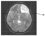
組織イメージング技術
図1Aは、脳腫瘍のある患者の手術前MRIスキャン100を示す図である。図1Bは、同じ患者の頭蓋骨を開頭後のその患者の露出した脳102の全体像を示す図である。図1Bに示すように、正常な脳組織と脳腫瘍を視覚的に見分けるのは困難である。腫瘍を除去する際に最適な手術結果を得る上での制限要因は、癌性脳組織と非癌性脳組織は肉眼では見分けがつかない場合があるため、相当な腫瘍がすべていつ除去されたかを把握することである。従って、切除をガイドするための高度な画像診断技術を用いることが望ましい。
Tissue Imaging Technique FIG. 1A is a diagram showing a preoperative MRI scan 100 of a patient with a brain tumor. FIG. 1B is a diagram showing an overall picture of the exposed
ラマン散乱では、分子振動を励起しながら分子によって励起光子を散乱させる。各分子結合タイプは、比剛性(例えば、C=C結合はC-C結合より強い)と関連する質量(例えば、C-CはC-Hより重い)、ひいては特定の振動周波数を有する。分散したラマン散乱スペクトルは、サンプルの分子振動によって測定され、そのサンプルの化学組成から算出される。 In Raman scattering, excited photons are scattered by molecules while exciting molecular vibrations. Each molecular binding type has a specific stiffness (eg, C = C bonds are stronger than CC bonds) and associated mass (eg, CC is heavier than CH), and thus has a specific vibration frequency. The dispersed Raman scattering spectrum is measured by the molecular vibration of the sample and calculated from the chemical composition of the sample.
脳神経外科の現場における腫瘍浸潤の検出には、自発ラマン分光法をうまく適用することができる。自発ラマン分光法は、積分時間が長いことから点取得に限られることが多く、また、コヒーレントラマン散乱イメージングの空間分解能を欠いていることも多く、診断にはスペクトル解析に頼ることになる。例えば、MRIにおける基本的な分光法である核磁気共鳴(NMR)は、研究用途において広く用いられているが、その臨床的使用は限られている。いずれの場合も、組織構造に関する重要な診断情報が提供されるが、医師は、医学的な意思決定を行うにあたって点スペクトルよりも画像の方を選ぶ。 Spontaneous Raman spectroscopy can be successfully applied to detect tumor infiltration in the field of neurosurgery. Spontaneous Raman spectroscopy is often limited to point acquisition due to its long integration time, and often lacks the spatial resolution of coherent Raman scattering imaging, relying on spectral analysis for diagnosis. For example, magnetic resonance imaging (NMR), which is the basic spectroscopy in MRI, is widely used in research applications, but its clinical use is limited. In each case, important diagnostic information about tissue structure is provided, but physicians prefer images to point spectra when making medical decisions.
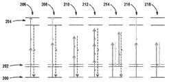
コヒーレント反ストークスラマン散乱(CARS)及び誘導ラマン散乱(SRS)を含むコヒーレントラマン散乱(CRS)によれば、自発ラマン信号の増幅が可能となる。図2は、CARSプロセス214とSRSプロセス218のエネルギー図を示す。CARS214とSRS218のどちらの場合も、サンプルがポンプで励起され、差周波数が分子振動の周波数と一致するようストークスビームが構成される。SRS218では、分子群が仮想状態を通ることにより基底状態200から振動励起状態202に励起される。その結果、ポンプ光子が生成され、ストークス光子が吸収される。CARS214では、第2ポンプ光子が散乱して、反ストークス周波数で新しい光子が生成される。
Coherent Raman scattering (CRS), including coherent anti-Stoke Raman scattering (CARS) and induced Raman scattering (SRS), allows amplification of spontaneous Raman signals. FIG. 2 shows energy diagrams of
SRS218は、CARS214と同じ照明条件で励起されるが、検出が異なる。CARS214は、発光が励起ビームの波長とは異なる波長で検出されるという点で蛍光と似ている。SRS218は、一つの励起ビーム(例えば、誘導ラマン損失)の吸収が第2ビームの存在下で測定されるという点で吸収と似ている。SRS218は高感度であるが、その検出には、高周波位相敏感検波スキーム(例えば、ロックイン検出)により、レーザー背景から比較的小さい信号を抽出することが含まれてもよい。SRS218は、励起スペクトルが自発ラマンと同一であるので、化学的特異性に対して固有の機能を発揮する。SRS218のもう一つの利点は、特別な光学的遮蔽なしに周囲光条件下で機能するということである。 SRS218 is excited under the same illumination conditions as CARS214, but with different detections. CARS214 is similar to fluorescence in that the emission is detected at a wavelength different from that of the excitation beam. SRS218 is similar to absorption in that the absorption of one excitation beam (eg, induced Raman loss) is measured in the presence of a second beam. Although SRS218 is sensitive, its detection may include extracting a relatively small signal from the laser background by a high frequency phase sensitive detection scheme (eg, lock-in detection). Since the excitation spectrum of SRS218 is the same as that of spontaneous Raman, SRS218 exerts a unique function for chemical specificity. Another advantage of the SRS218 is that it works under ambient light conditions without any special optical shielding.
CARS214は、サンプルの透過又は反射モダリティ(いわゆるepi検出)において検出可能である。SRS218は、励起ビームの損失又は利得であるので、透過で検出されることが多い。しかしながら、サンプルの厚みが大きい場合、前方へ伝播するSRS218信号は、後方散乱し、反射モードで検出可能である。とはいえ、通常、最高の信号強度と画質は、サンプルの厚みが散乱の平均自由行程に対して小さい場合に得られる。 CARS214 is detectable in the transmission or reflection modality of the sample (so-called epi detection). Since SRS218 is the loss or gain of the excitation beam, it is often detected by transmission. However, if the sample is thick, the SRS218 signal propagating forward is backscattered and can be detected in reflection mode. However, the best signal strength and image quality are usually obtained when the sample thickness is small relative to the mean free path of scattering.
また、図2には、他の多光子顕微鏡法(MPM)及び分光法も示す。2光子励起蛍光(TPEF)206では、2つの励起光子を同時に吸収して、基底状態200から電子的に励起された状態204に分子群を励起し、そこから、TPEF顕微鏡法で検出された信号である蛍光発光の下で弛緩する。2色2光子励起蛍光(TCTPEF)208による励起では、異なる波長の2つの光子が同時に吸収される。その吸収216又は蛍光発光208が顕微鏡法における信号として測定される。TPEF206及びTCTPEF208は、固有の組織種、要素又は因子から生じることもあれば、フルオロフォアの外色素から生じることもある。通常、TPEF206及びTCTPEF208は、サンプルの発光が等方性を有しているので、反射モードで検出される。蛍光信号についても、一光子励起手段で励起可能である。そして、焦点外の光は、共焦点ピンホールによりカットされる。第2高調波発生(SHG)210及び第3高調波発生(THG)212では、信号の放出が励起波長のちょうど2倍又は3倍である。SHG210は、例えば、コラーゲンのイメージングにおいて周知である。THG212は、非線形屈折率を測定し、脳組織において腫瘍浸潤を特徴付けるのに用いることができる。THG212の画像は、CRSの画像と似ているところもあるが、核特異的コントラストを欠いている。従って、さまざまな面で、現在の技術には、これらの分光法を行う装置が含まれる。さまざまな実施例では、SRS装置、CARS装置、共焦点ラマン装置、共焦点反射装置、共焦点蛍光装置、OCT装置、TPEF装置、SHG装置、THG装置から成る群からイメージング装置が選択される。
FIG. 2 also shows other two-photon microscopy (MPM) and spectroscopy. In the two-photon-excited fluorescence (TPEF) 206, two excited photons are simultaneously absorbed to excite the molecular group from the
図3は、例示的なCRS顕微鏡システム300を示す模式図である。このシステム300では、ポンプ302とストークスビーム304がダイクロイックミラー306で重畳して、共線ビームを生成する。励起は、通常、中程度の平均出力で高ピーク出力を有するパルスレーザーにより行われ、サンプルにダメージを与えずに非線形CRS信号を励起する。従って、このシステム300では、サンプルにおいてパルスを時間的に重ね合わせるように、2つのパルス列の相対的な遅延を調整する遅延線308がビーム路のうちの少なくとも一つに含まれる。共線ビームは、対物レンズ312によって、サンプル310に集光させる。ガルバノ走査ミラー314によれば、決定論的方法により(通常、コンピュータ又は電子制御下で)サンプル310において共通焦点体積がスキャンされる。SRSの場合、透過時に集光レンズ316により信号が収集され、光学フィルタ318により光学的にフィルタ処理され、検出器320で検出されて、画素として信号が生成される。走査パターンを生成したコンピュータや電子機器は、その画素を画像に再配置するのに用いられる。通常、400μmの視野(FOV)を有する高開口数(NA)対物レンズを用いることにより、良好な画質が得られる。ビーム走査型画像取得と電動状態を合わせることにより、より広範囲の画像を取得することができる。例えば、モザイクイメージングによれば、複数のXY画像を一つの大きな画像に縫い合わせることができる。例えば、各個別の視野は、1M個の画素(すなわち、1000×1000個の画素)を有する400μm×400μmの領域であってもよく、5×5のモザイクを縫い合わせることにより、25M個の画素を有する2mm×2mmの領域がカバーされることになる。また別の方法として、ガルバノ走査ミラー314ではたった一つの軸に沿ってしかデータ取得が行われず、他の軸は電動ステージによるものである場合に、ストリップタイリングを用いることもできる。この例では、400μm×2mmのストリップを一回の取得動作で走査することができる。
FIG. 3 is a schematic diagram showing an exemplary
歴史的に見て、SRSは、2つの正確に同期した調節可能な超短(ピコ秒)レーザーパルス列を必要とするため、その臨床現場における実施や操作は困難で費用がかかるものと考えられてきた。ここでは、いくつかの変形例において、本技術は、ファイバコアによる導光のためにロバストで、電気通信業界の規模の経済のために比較的安価なカスタム2波長ファイバレーザー光源を採用してもよい。カスタム2波長ファイバレーザー光源を有するプロトタイプシステムは、例えば、手術室に設置して、顕微鏡法に関する広範囲の訓練を受けていないユーザによって操作が可能である。 Historically, SRS has been considered difficult and costly to implement and operate in clinical settings, as it requires two precisely synchronized, adjustable ultrashort (picosecond) laser pulse trains. rice field. Here, in some variants, the technique employs a custom dual wavelength fiber laser light source that is robust for light guidance by the fiber core and is relatively inexpensive for economies of scale in the telecommunications industry. good. A prototype system with a custom dual wavelength fiber laser light source can be installed, for example, in an operating room and operated by a user who has not received extensive training in microscopy.
CRSの励起ビームを得るには、異なるレーザー光源を用いてもよい。大学の研究室の多くでは、固体光パラメトリック発振器(OPO)ベースのシステムを用いて、同期した2つのパルス列302、304を生成する。他の方法には、キャビティ長に関するフィードバック又はパルスオンデマンドの解決策により、2つの独立したレーザーの電子同期を行うことが含まれる。CRS顕微鏡のファイバレーザーベースの実装では、OPOシステムと同様の非常にロバストな光同期を採用することができる。レーザー光源は、2つの主要なファイバ利得媒体、エルビウム(Er)及びイッテルビウム(Yb)の周波数差がラマンスペクトルの高波数領域と重なることに基づいている。つまり、パルス列324がエルビウム(Er)添加発振器322によって生成され、その後、光学スプリッタ326によって分割される。一つのアームがエルビウム添加ファイバ増幅器328で増幅されて、第1パルス列302を生成する。このファイバ増幅器328の後に第2高調波発生ユニットをさらに備え、増幅器328の出力の周波数を2倍にして第1パルス列302を得ることが可能である。第2アームは、例えば、スーパーコンティニウムや調節可能な狭帯域フィルタにより、周波数シフトユニット330で周波数シフトされる。その後、周波数シフトされた出力は、イッテルビウム(Yb)添加増幅器332で増幅されて、第2パルス列304が得られる。
Different laser light sources may be used to obtain the CRS excitation beam. Many university laboratories use solid-state optical parametric oscillator (OPO) -based systems to generate two synchronized pulse trains 302, 304. Other methods include electronic synchronization of two independent lasers with feedback on cavity length or pulse-on-demand solutions. Fiber laser-based implementations of CRS microscopes can employ very robust optical synchronization similar to OPO systems. The laser source is based on the fact that the frequency difference between the two major fiber gain media, erbium (Er) and ytterbium (Yb), overlaps the high frequency region of the Raman spectrum. That is, the
さまざまな実施例では、システム300は、(1)約10MHzから約100MHzの繰り返し率で0.5から10psのパルス幅を有する約600nmから約1000nmのポンプビームについて、約50から約500mWの平均出力と、(2)約900nmから約1100nmの調節可能なストークスビームについて、約50mWから約1000mWの平均出力と、(3)約100fs以下のタイミングジッタが得られるよう構成されている。このシステム300は、約5秒以下、約2秒以下、又は、約1秒以下で画像を生成することが可能である。多色取得の波長同調は、通常、フレームとフレームの間に行われる。そして、広範囲のモザイク画像は、約5分以内、約4分以内、約3分以内、約2分以内、又は、約1分以内に取得可能である。一実施例では、システム300は、(1)2psのパルス幅と80MHzの繰り返し率を有する790nmに固定波長のポンプビームについて、300mWの平均出力と、(2)1010nmから1045nmの調節可能なストークスビームについて、約500mWの平均出力と、(3)約50fs以下のタイミングジッタが得られるよう構成されている。このシステム300は、2800cm-1から3100cm-1のラマン範囲に対応している。このようなシステム300によれば、1分足らずで、0.6nm解像度の新鮮な外科標本から、2mm×2mm領域の25M画素の2色SRS画像を生成することが可能である。
In various embodiments, the system 300 (1) has an average output of about 50 to about 500 mW for a pump beam of about 600 nm to about 1000 nm with a pulse width of 0.5 to 10 ps at a repetition rate of about 10 MHz to about 100 MHz. And (2) an average output of about 50 mW to about 1000 mW and (3) timing jitter of about 100 fs or less can be obtained for an adjustable Stokes beam of about 900 nm to about 1100 nm. The
ファイバレーザーベースのマルチモーダルSRS顕微鏡400の一例を図4に示す。この顕微鏡400は、オリンパス顕微鏡本体402と、ファイバデリバリ技術によりシームレスにレーザー光源406を結合するビーム走査ユニット404から構成されている。レーザーと顕微鏡400は、コンピュータ412により制御電子機器408(レーザー)、410(顕微鏡)を介して制御されている。イメージングデータは、画面414に表示される。一実施例では、イメージングソフトウェアは、オープンソースの顕微鏡プラットフォーム、μマネージャに基づいている。それにより、イメージング、レーザー、ステージパラメータを完全に制御することが可能となり、多色モザイクイメージングのアルゴリズムが得られる。すべての構成要素(400乃至414)を移動式のカート416に搭載して、完全一体型のマルチモーダルSRS顕微鏡を構成することができる。
An example of a fiber laser-based
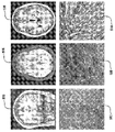
図5は、側頭葉切除を受けたてんかん患者500、低グレードの乏突起膠腫を持つ患者504、高グレードの神経膠腫を持つ患者508からファイバレーザーベースのSRSプロトタイプシステムにより得られたSRS画像を示す。対応するSRS画像は、まばらな細胞質と多くの軸索で特徴付けられた正常なヒトの大脳皮質502、円形の核と豊富な細胞質を持つ特徴的な腫瘍細胞を有する低グレードの乏突起膠腫を持つ人間の脳506、偽柵状配列パターンに細胞が密集した高グレードの神経膠腫を持つ人間の脳510を示す。重要な点は、正常脳と腫瘍浸潤脳では顕微鏡で見た形状に違いがあるということである。
FIG. 5 shows SRS obtained by a fiber laser-based SRS prototype system from 500 patients with epilepsy who underwent temporal lobe resection, 504 with low grade oligodendroglioma, and 508 with high grade glioma. The image is shown. Corresponding SRS images are normal human
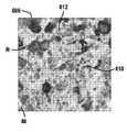
SRS顕微鏡法では、神経病理学で最もよく使用される染色であるヘマトキシリン及びエオジン(H&E)として類似した形態学的特徴をハイライトした画像が生成される。図6Aは、組織内の脂質600、タンパク質602、DNA604などの共通分子のラマンスペクトルを示す。複数のラマンシフト(例えば、2850cm-1及び2930cm-1又は2850cm-1、2930cm-1及び2960cm-1など)において組織のイメージングを行い、スペクトル非混合技術を用いることにより、例えば、H&E染色を模倣して図6Bの606に青と緑で又は図6Cの608にピンクと紫で示すように、異なる疑似色で表示可能な多色SRS画像を生成することができる。CH2振動(2845cm-1)のSRS画像は、有髄軸索や細胞外基質610など、脂質の多い構造を示す。CH3振動(2930cm-1)のSRS画像は、核やコラーゲン繊維612など、プロテインやDNAを豊富に含む構造を示す。図6Dは、低グレードの神経膠腫の1.5mm×1.5mm領域のステッチ画像を示す。
SRS microscopy produces images highlighting similar morphological features as hematoxylin and eosin (H & E), the most commonly used stains in neuropathology. FIG. 6A shows Raman spectra of common molecules such as
SRS顕微鏡法は、脳腫瘍における腫瘍境界の描出に有効である。図7A乃至図7Dは、ヒト神経膠腫異種移植マウスモデルにおけるSRS画像とH&E組織構造画像の比較を示す。まずは、SRSにより薄い凍結した部分のイメージングが行われ、その後、H&Eで染色されることにより、同一の組織に関して方法の比較を行うことができる。図7Aは、マウス脳の全断面図を示す。図7Bは、正常又はわずかな過形成皮質組織(25%未満の腫瘍浸潤)の高倍率図を示す。図7Cは、正常な白質束(星印)、腫瘍浸潤束(矢印)、高密度腫瘍細胞(矢)を有する浸潤性神経膠腫(25%から75%の腫瘍浸潤)を示す。図7Dは、高密度な神経膠腫(75%以上の腫瘍浸潤)を示す。これらの画像は、ウェブ上の調査に入力して、SRSとH&E顕微鏡法を定量的に比較するのに用いられる。腫瘍浸潤度を特徴付けるSRSと標準H&E染色間の方法間の一致は優良(k=0.98)である。 SRS microscopy is effective in delineating tumor boundaries in brain tumors. 7A-7D show a comparison of SRS and H & E tissue structure images in a human glioma xenograft mouse model. First, a thin frozen portion is imaged by SRS and then stained by H & E, so that method comparisons can be made for the same tissue. FIG. 7A shows a full cross-sectional view of the mouse brain. FIG. 7B shows a high magnification diagram of normal or slight hyperplastic cortical tissue (less than 25% tumor infiltration). FIG. 7C shows an invasive glioma (25% to 75% tumor infiltration) with normal white matter bundles (stars), tumor infiltrating bundles (arrows), and dense tumor cells (arrows). FIG. 7D shows high density glioma (more than 75% tumor infiltration). These images are input to a survey on the web and used to quantitatively compare SRS and H & E microscopy. The agreement between the methods that characterize tumor infiltration between SRS and standard H & E staining is excellent (k = 0.98).
また、SRSは、22人の神経外科患者から得られた新鮮な未処理の外科標本60にも有効である。SRSは、標準のH&E光学顕微鏡法とほぼ完璧な一致で腫瘍浸潤を検出した。SRS顕微鏡法に特有の化学的コントラストは、組織の細胞性、軸索密度、腫瘍浸潤組織のタンパク質:脂質比における定量化可能な変化を明らかにすることにより腫瘍の検出を可能にする。 SRS is also effective in fresh, untreated surgical specimens 60 from 22 neurosurgical patients. SRS detected tumor infiltration in near perfect agreement with standard H & E light microscopy. The unique chemical contrast of SRS microscopy allows tumor detection by revealing quantifiable changes in tissue cellularity, axonal density, and protein: lipid ratio of tumor infiltrating tissue.
図8A乃至図8Hは、ヒトの外科標本におけるSRS画像とH&E組織構造画像の比較を示す。図8Aは、SRSとH&Eでイメージングが行われたリング状造影を示す膠芽腫(GBM;矢)のMRI画像を示す。図8Bは、SRS(左)とH&E(右)顕微鏡法の両方に生存腫瘍の過形成と核異型が見られることを示す。図8Cでは、微小血管増殖により、SRS顕微鏡法(左、矢)ではっきりと認められ、過ヨウ素酸シッフ染色(右、矢)でハイライトされた蛇行性血管複合体が生成される。図8Dに示すように、SRS顕微鏡法(左)とH&E染色(右)により、有糸分裂像も見られる(矢)。非造影の低グレード乏突起膠腫のMRI画像を図8Eに示す。図8Fに示すように、乏突起膠腫は、ニューロフィラメント免疫染色(右)により確認されるように、SRSイメージング(左)に最小限の軸索破壊を引き起こす「目玉焼き」状の形態(矢)の巣を有する過形成組織からなる。図8Gでは、SRS(左)とH&E(右)顕微鏡法により、「金網」血管(矢)のイメージングが行われる。図8Hでは、SRS(左)とH&E(右)顕微鏡法の両方に神経周囲浸潤が見られる。 8A-8H show a comparison of SRS images and H & E tissue structure images in human surgical specimens. FIG. 8A shows an MRI image of glioblastoma (GBM; arrow) showing ring contrast imaged with SRS and H & E. FIG. 8B shows that both SRS (left) and H & E (right) microscopy show hyperplasia and nuclear atypia of viable tumors. In FIG. 8C, microvascular proliferation produces a tortuous vascular complex that is clearly visible by SRS microscopy (left, arrow) and highlighted by periodic acid-Schiff staining (right, arrow). As shown in FIG. 8D, mitotic images are also seen by SRS microscopy (left) and H & E staining (right) (arrows). An MRI image of an uncontrast low-grade oligodendroglioma is shown in FIG. 8E. As shown in FIG. 8F, oligodendroglioma has a "fried egg" -like morphology (arrow) that causes minimal axonal destruction in SRS imaging (left), as confirmed by neurofilament immunostaining (right). Consists of hyperplastic tissue with nests. In FIG. 8G, "wire mesh" blood vessels (arrows) are imaged by SRS (left) and H & E (right) microscopy. In FIG. 8H, perineural infiltration is seen in both SRS (left) and H & E (right) microscopy.
生検装置及びイメージング
腫瘍浸潤度や切除を継続するか否かに時間遅延なくアクセスするための露出した外科的キャビティの表面から、できるだけ小さいが(神経障害のリスクを最小限に抑えるのに)診断上適切な量の組織生検を取ることを可能にする生検装置と併用して、SRSや他の光学イメージング又は分光法技術を使用することが望ましい。図5の画像の取得については、切断機構を用いた標準の脳神経外科生検鉗子(例えば、B.Braun、ペンシルバニア州ベツレヘム)により行われた。240μmスペーサ(Grace Biolabs社、オレゴン州ベンド)を用いて圧縮状態の保持した顕微鏡スライドと1.5番カバースリップとの間に小さい組織片を載置した。この変形例では、画質が優良ではあるが、サンプル処理がやや煩雑なため、神経外科ワークフローに組み込むにはやや不向きである。
Biopsy device and imaging Diagnosis as small as possible (to minimize the risk of neuropathy) from the surface of an exposed surgical cavity for time-lag access to tumor invasion and whether to continue excision It is desirable to use SRS or other optical imaging or spectroscopic techniques in combination with a biopsy device that allows an appropriate amount of tissue biopsy to be taken. The acquisition of the image of FIG. 5 was performed with standard neurosurgery biopsy forceps using a cutting mechanism (eg, B. Braun, Bethlehem, PA). A small piece of tissue was placed between the microscope slide held in compression and the No. 1.5 coverslip using a 240 μm spacer (Grace Biolabs, Bend, Oregon). In this variant, the image quality is excellent, but the sample processing is rather cumbersome, making it somewhat unsuitable for incorporation into neurosurgical workflows.
鉗子などの脳神経外科用手術器具にイメージング用光学窓を含むよう適合させるのは、可動部品が多く、薄く平らなサンプルを得るための懸念や、生検される組織量を最小限に抑える必要性があることから、非常に難しく、費用がかかる場合がある。 Adapting neurosurgical instruments such as forceps to include an optical window for imaging has many moving parts, concerns about obtaining thin, flat samples, and the need to minimize the amount of tissue to be biopsied. Because of this, it can be very difficult and expensive.
針生検(CNB)や微細針吸引生検(FNA)用の器具が開発されている。これらの針ベースの装置は、生検標本を得るために、所望の組織やサンプルに向かって患者の体内に切り込んでいったり繋ぎ合わせたりするよう設計されている。光学イメージングや分光法の動機は、誤った生検率を減らすことや、分子技術に関する診断用腫瘍量を増やすことにある。針は、一般的に、金属製であり、サンプルを切断したり皮膚や他の組織を貫通するのに鋭い刃を有している。針は、通常、鋭い刃に関わるリスクが存在するため、開腹手術には用いられない。 Instruments for needle biopsy (CNB) and fine needle aspiration biopsy (FNA) have been developed. These needle-based devices are designed to cut and splice into the patient's body towards the desired tissue or sample to obtain a biopsy specimen. The motivation for optical imaging and spectroscopy is to reduce false biopsy rates and increase the amount of diagnostic tumors associated with molecular techniques. Needles are generally made of metal and have sharp blades for cutting samples and penetrating skin and other tissues. Needles are usually not used in open surgery because of the risk associated with sharp blades.
患者へのリスクを最小限に抑えつつ、組織表面から生検を得る方法は、タッチプレップやスカッシュプレップとして知られている。この方法により細胞学的検査が可能となるが、組織構造が保存されないことが多く、それによって技術の診断精度が大幅に制限されてしまう場合がある。 A method of obtaining a biopsy from the tissue surface while minimizing the risk to the patient is known as touch prep or squash prep. Although this method allows cytological examination, it often does not preserve the tissue structure, which can significantly limit the diagnostic accuracy of the technique.
脳神経外科で使用される器具は、通常、陰圧、すなわち、吸引力を利用し、密集した組織を解体する超音波(例えば、キャビトロン超音波外科用吸引装置;CUSA)と併用されることが多い。ここでの目標は、効果的に組織を除去することである。ある態様では、生検標本の抽出に、切断や圧縮ではなく、吸引力を利用する生検装置を用いることが望ましい。そのようなシステムによれば、生検装置と既存の外科ワークフローの一体化を可能にしつつ、迅速な組織学的分析のために被検者から摘出された生体サンプルの細胞構築や完全性の保存がより良好に行われる。また、光学イメージングを行うのに十分なくらい収集チャネルを薄くし、大きな変形や診断上関連する組織構造の損失を引き起こし得る神経障害を回避できるほどサンプリング量を抑えることが望ましい。 Instruments used in neurosurgery are often used in combination with ultrasound (eg, Cavitron ultrasonic surgical suction device; CUSA) that uses negative pressure, or suction, to disassemble dense tissue. .. The goal here is to effectively remove the tissue. In some embodiments, it is desirable to use a biopsy device that utilizes suction rather than cutting or compression to extract the biopsy specimen. Such a system allows the integration of biopsy equipment with existing surgical workflows, while at the cost of cytoarchitecture and preservation of integrity of biological samples removed from subjects for rapid histological analysis. Is done better. It is also desirable to make the collection channel thin enough to perform optical imaging and to reduce the sampling amount to avoid neuropathy that can cause large deformations and loss of diagnostically related tissue structures.
開腹手術中に生検標本の採取及びイメージングを行うための器具の使用や方法を改善する必要性に対処するため、本技術は、組織変形を軽減し、同時に、組織に関する組成及び/又は構造情報が得られるリアルタイムの品質画像を提供するための生検チップ、装置及び方法を提供する。 To address the need to improve the use and method of instruments for collecting and imaging biopsy specimens during open surgery, the technique reduces tissue deformation while simultaneously providing composition and / or structural information about the tissue. Provide biopsy chips, devices and methods for providing real-time quality images obtained.
従って、さまざまなチャネル高さ及び幅を有する長方形のガラス毛管(VitroComから市販されている)を吸引装置に接続して生検装置が構成された。この生検装置は、ビルの壁内を循環するビルの真空システム、真空ポンプ、自律的に吸引力を発生させる独立システム(非限定の例として、Stryker(登録商標)Surgicalから市販されているネプチューン(登録商標)(NEPTUNE)2ウェイストマネジメントシステムなど)によって与えられる吸引力など、当技術分野で使用される陰圧、すなわち、吸引力の固定式又は移動式の供給源で駆動する。このような装置は、脳組織を吸い上げるのに用いられる。チャネルが約200μm以上の高さを有する場合に組織の吸引が効率的に行われるが、ビルにより供給された吸引力は、超音波吸引なしに100μmのチャネルに組織を吸い上げたり吸引したりできるほど強力な吸引力である。 Therefore, a rectangular glass capillary (commercially available from VitroCom) with various channel heights and widths was connected to the suction device to construct a biopsy device. This biopsy device is a building vacuum system that circulates within the walls of the building, a vacuum pump, and an independent system that autonomously generates suction (as a non-limiting example, Neptune commercially available from Striker® Surgical). It is driven by a negative pressure, i.e., a fixed or mobile source of suction, as used in the art, such as the suction force provided by (NEPTUNE) 2 waste management system, etc.). Such devices are used to suck up brain tissue. Tissue suction is efficient when the channel has a height of about 200 μm or higher, but the suction force supplied by the building is sufficient to suck or suck tissue into a 100 μm channel without ultrasonic suction. It is a strong suction force.
組織サンプルは、生検装置で取得された後、図4に示すファイバレーザーベースのSRS顕微鏡400で分析が行われ、透過型SRSでイメージングが行われた。チャネルの高さが約500μm以下、約400μm以下、約300μm以下、約200μm以下、約100μm以下の場合に、十分な画質が得られる。図13Aは、チャネル高さが200μm、チャネル幅が4mm、壁厚が200μmの長方形のガラス毛管で得られた2色SRS画像を示す。意外にも、図5の画像を得るのに使用するカバースリップ、カバースライド、両面テープを用いたより煩雑なサンプル調製と比べて、画質の明らかな損失や、組織変形又は血液による干渉の兆候はなかった。また、屈折率のマッチングには、追加の液体が必要とされなかった。画像は、非重複色チャネルを生じさせるサンプルドリフト、ステージヒステリシス、揺動又は非直線運動を示していない。
Tissue samples were obtained on a biopsy device and then analyzed with a fiber laser-based
図9は、生体サンプル950を収容する生検装置900を示す図である。この装置900は、第1開口部904と第2開口部906を有する本体902と、少なくとも部分的に光透過性を有する壁908の少なくとも一部とから構成されている。本体902は、組織などの生体サンプル950を収容するチャネル910を画定する。陰圧912の供給源が第1開口部904に印加されて、生体サンプル950が第2開口部906からチャネル910内へと引き込まれる。この生体サンプル950の画像は、少なくとも部分的に光透過性を有する壁908の一部を介して得られる。いくつかの実施例では、この生検装置900は、任意のバックストップ又は有孔壁914をさらに備えている。このバックストップ又は壁は、陰圧がバックストップ又は有孔壁914を横断できるように複数の穴又はポアを有している。バックストップ又は壁914は、組織が生検装置900から飛び出すのを防ぎ、組織を装置900のイメージングに適した領域に保持する。
FIG. 9 is a diagram showing a biopsy device 900 accommodating a
一実施例では、上記装置は、少なくとも部分的に長方形の断面形状を有する領域を有している。この形状により、装置の異なる領域のフォーカシングを行うオートフォーカスを繰り返し行わずに、組織のイメージングが単純化され、及び/又は、光学収差が軽減される。一方で、生検中に除去する組織量を最小限に抑え、チャネルを狭く保つことが有利である。他方で、診断精度を向上させるのに可能な限り大量の組織量を得ることが有利である。このトレードオフは応用特有のものである。例えば、装置においてサンプルのイメージングが行われる領域は、イメージングが行われる軸と、圧力が印加される軸の両方に直交する寸法(「x寸法」)が、約100μmから約15mm、約500μmから約10mm、又は、約1mmから約5mmの範囲である。さまざまな実施例では、このx寸法は、約100μm、約200μm、約500μm、約1mm、約2mm、約3mm、約4mm、約5mm、約6mm、約7mm、約8mm、約9mm、約10mm、約11mm、約12mm、約13mm、約14mm、又は、約15mmである。この装置においてサンプルのイメージングが行われる領域は、イメージングが行われる軸に沿った寸法(「y寸法」)が、約50μmから約1000μmの範囲である。さまざまな実施例では、このy寸法は、約1000μm以下、約500μm以下、約400μm以下、約300μm以下、約200μm以下、又は、約100μm以下である。いくつかの実施例では、y寸法は、約10μmから約1000μm、約50μmから約400μm、約100μmから約300μm、又は、約150μmから約250μmである。従って、さまざまな実施例では、イメージングが行われる軸に沿った装置の寸法は、約500μm、約450μm、約400μm、約350μm、約300μm、約350μm、約300μm、約250μm、約200μm、約150μm、又は、約100μmである。この装置においてサンプルのイメージングが行われる領域は、イメージングが行われる軸と、圧力が印加される軸に直交する寸法(「z寸法」)が、約100μmから約30mm、約1mmから約20mm、約1mmから約15mm、又は、約5mmから約10mmの範囲である。さまざまな実施例では、このz寸法は、約100μm、約200μm、約500μm、約1mm、約2mm、約3mm、約4mm、約5mm、約6mm、約7mm、約8mm、約9mm、約10mm、約15mm、約20mm、約25mm、又は、約30mmである。従って、さまざまな実施例では、この装置は、x:y:z寸法が約100μm:50μm:100μmから約15mm:1000μm:30mm、又は、約1mm:100μm:1mmから約10mm:250μm:15mmの領域を有する。一実施例では、この装置は、x:y:z寸法が約10mm:200μm:15mmの領域を有する。 In one embodiment, the device has a region having at least a partially rectangular cross-sectional shape. This shape simplifies tissue imaging and / or reduces optical aberrations without repeated autofocus to focus different areas of the device. On the other hand, it is advantageous to minimize the amount of tissue removed during the biopsy and keep the channel narrow. On the other hand, it is advantageous to obtain as much tissue mass as possible to improve diagnostic accuracy. This trade-off is application-specific. For example, in the region where the sample is imaged in the device, the dimension (“x dimension”) orthogonal to both the axis where the imaging is performed and the axis where the pressure is applied is from about 100 μm to about 15 mm and from about 500 μm to about 500 μm. It is in the range of 10 mm, or about 1 mm to about 5 mm. In various embodiments, the x-dimensions are about 100 μm, about 200 μm, about 500 μm, about 1 mm, about 2 mm, about 3 mm, about 4 mm, about 5 mm, about 6 mm, about 7 mm, about 8 mm, about 9 mm, about 10 mm, It is about 11 mm, about 12 mm, about 13 mm, about 14 mm, or about 15 mm. The region in which the sample is imaged in this device has a dimension (“y dimension”) along the axis on which the imaging is performed, ranging from about 50 μm to about 1000 μm. In various embodiments, the y dimension is about 1000 μm or less, about 500 μm or less, about 400 μm or less, about 300 μm or less, about 200 μm or less, or about 100 μm or less. In some embodiments, the y dimension is from about 10 μm to about 1000 μm, from about 50 μm to about 400 μm, from about 100 μm to about 300 μm, or from about 150 μm to about 250 μm. Thus, in various embodiments, the dimensions of the device along the axis on which the imaging is performed are about 500 μm, about 450 μm, about 400 μm, about 350 μm, about 300 μm, about 350 μm, about 300 μm, about 250 μm, about 200 μm, about 150 μm. Or, it is about 100 μm. In this device, the area where the sample is imaged has dimensions (“z dimension”) orthogonal to the axis on which the imaging is performed and the axis to which pressure is applied, from about 100 μm to about 30 mm, from about 1 mm to about 20 mm, and about. It ranges from 1 mm to about 15 mm, or from about 5 mm to about 10 mm. In various embodiments, the z dimensions are about 100 μm, about 200 μm, about 500 μm, about 1 mm, about 2 mm, about 3 mm, about 4 mm, about 5 mm, about 6 mm, about 7 mm, about 8 mm, about 9 mm, about 10 mm, It is about 15 mm, about 20 mm, about 25 mm, or about 30 mm. Thus, in various embodiments, the device has a region of x: y: z dimensions from about 100 μm: 50 μm: 100 μm to about 15 mm: 1000 μm: 30 mm, or from about 1 mm: 100 μm: 1 mm to about 10 mm: 250 μm: 15 mm. Have. In one embodiment, the device has a region with x: y: z dimensions of about 10 mm: 200 μm: 15 mm.
さまざまな実施例では、陰圧の供給源は、部屋の壁からアクセス可能なビルの真空システム、自律的に吸引力を発生させる独立システム、又は、ポンプである。他の実施例では、上記装置は、図10に示すように外科吸引装置922と結合する生検チップ920として構成される。この吸引装置922は、剛性を有していても柔軟性を有していてもよい縦本体923を備えている。この生検チップ920は、ビルの真空システム又はポンプへのアクセスを与える壁など、吸引力又は陰圧924の供給源に接続された外科吸引装置922に取り付け可能である。この吸引装置922は、外科医の手926に保持される。図10に示すように、いくつかの実施例では、吸引装置922は、吸引力源924から周囲環境への低抵抗パスを形成する開口部又は開口928を有する。この開口部を、例えば、外科医の親指930で、部分的又は完全に覆うことにより、生検チップ920の開口部に印加される吸引量の微調整が可能である。この吸引装置922及び生検チップ920は、例えば、外科クランプ936で皮膚を保持しながら、露出した脳組織934の外科キャビティ932から生検を採取するのに使用可能である。この吸引装置922は、以下にさらに説明するように、吸引装置922及び/又は生検チップ920のナビゲーション追跡を行う受動又は能動マーカ938をさらに備えていてもよい。また、ナビゲーション追跡(例えば、光学的又は電磁的)用の受動又は能動マーカは、各生検チップの一部として備えられていてもよい。マーカのさまざまな機能は、さまざまな生検チップのエンコードを行うのに用いられてもよい。
In various embodiments, the source of negative pressure is a building vacuum system accessible from the walls of the room, an independent system that autonomously generates suction, or a pump. In another embodiment, the device is configured as a
イメージングは、アセンブリ全体(吸引装置922及び生検チップ920)のイメージングを行うことにより、又は、吸引装置922から生検チップ920を取り外して、生検チップ920だけを別個にイメージャに装着することにより実行することができる。前者の場合は、イメージングシステムは滅菌状態であることが好ましい。後者の場合は、外科医がもう一つの生検チップを装着して、さらに複数のサンプルを迅速に採取してもよい。他の実施例では、吸引装置922に接続した生検チップ920により外科的切除を行なってもよい。組織病理の決定が必要なポイントに外科医が達すると、その外科医が吸い上げた最後の組織片がイメージングを行うサンプルとして用いられてもよい。
Imaging is performed by imaging the entire assembly (suction device 922 and biopsy chip 920), or by removing the
図11は、標準的な(V.Mueller;カリフォルニア州サンディエゴ)脳神経外科用吸引装置962に取り付けられた例示的な生検チップ960の写真を示す。この吸引装置962は、剛性又は柔軟性を有する縦本体963を備えている。この吸引装置962は、パイプやチューブ964によって、病院の真空システムなどの固定式の陰圧源に取り付けられている。吸引は、真空システムに関連するバルブや圧力調整器によって調節されてもよく、手術の現場でも、外科医が吸引装置962の開口又は開口部966を自身の親指968で閉じることにより局所的に調節されてもよい。
FIG. 11 shows a photograph of an
さまざまな実施例では、生検チップ全体が、少なくとも部分的に光透過性を有する材料でできており、この生検チップの反射モード又は透過モード時にサンプルから画像を得ることができる。他の実施例では、この生検チップのほんの一部だけが少なくとも部分的に光透過性であり、反射モードでイメージングが実行される。さらに他の実施例では、サンプルの対向する両側における生検チップの部分が少なくとも部分的に光透過性であるのに対し、生検チップの他の部分は非透過性であり、反射モード又は透過モードのいずれかでイメージングを実行することができる。 In various embodiments, the entire biopsy chip is made of a material that is at least partially light transmissive, and images can be obtained from the sample during the reflection or transmission mode of the biopsy chip. In another embodiment, only a small portion of this biopsy chip is at least partially light transmissive and imaging is performed in reflective mode. In yet another embodiment, the portion of the biopsy chip on opposite sides of the sample is at least partially transmissive, while the other portion of the biopsy chip is opaque and either reflective mode or transmissive. Imaging can be performed in any of the modes.
さまざまな実施例では、790nm及び1010から1050nmのスペクトル領域の波長を有するビームによりイメージングが行われ、「光透過性」とは、これらの波長に対して透過性を有するものとしてとらえる。他の実施例では、励起ビームの波長は、約0.4μmから約10μm、約0.7μmから約10μm、約0.7μmから約2.1μm、約0.7μmから約1.6μm、約0.4μmから約1.1μm、約0.5μmから約1.1μmの範囲であってもよく、「光透過性」とは、これらの波長に対して少なくとも部分的に光透過性を有するものとしてとらえる。「部分的に光透過性」とは、約10%以上、約20%以上、約30%以上、約40%以上、約50%以上、約60%以上、約70%以上、約80%以上、約90%以上、約95%以上、約98%以上、又は、約99%以上の光透過性を有する材料を指す。反射防止膜を用いて、反射防止膜なしの場合に比べて透過性を向上させることができる。 In various examples, imaging is performed with beams having wavelengths in the spectral regions of 790 nm and 1010 to 1050 nm, and "light transmission" is considered to be transparent to these wavelengths. In another embodiment, the wavelength of the excitation beam is from about 0.4 μm to about 10 μm, from about 0.7 μm to about 10 μm, from about 0.7 μm to about 2.1 μm, from about 0.7 μm to about 1.6 μm, about 0. It may be in the range of 0.4 μm to about 1.1 μm and about 0.5 μm to about 1.1 μm, and “light transmission” means that it has light transmission at least partially for these wavelengths. Catch. "Partially light transmissive" means about 10% or more, about 20% or more, about 30% or more, about 40% or more, about 50% or more, about 60% or more, about 70% or more, about 80% or more. , About 90% or more, about 95% or more, about 98% or more, or about 99% or more light transmissive material. The antireflection film can be used to improve the transparency as compared with the case without the antireflection film.
上記生検装置は、イメージングに適した光学特性を有することを特徴とする材料でできている。この材料は、分化の可能性が低く、光学収差を生じさせず、複屈折性はなく、励起レーザー出力に耐えることができ、イメージングが行われる領域ではラマン活性ではなく、イメージングが行われるスペクトル領域ではラマン活性である。本明細書で用いられるように、「ラマン活性」とは、約2800cm-1から約3100cm-1などの特定のスペクトル領域でラマンシフト(ストークス又は反ストークス)を発生させる材料を指す。この材料からの信号は、組織画像に対して好ましくない背景信号を生じさせる場合があり、そのような場合には、スペクトル領域においてラマン活性ではない材料を使用することが好ましい。他の実施例では、上記材料からのラマン信号は、焦点がずれていて、材料がラマン活性であってもよいため、組織イメージングに干渉しない。この場合、イメージングシステムは、その材料内又はその付近でもイメージングを行って、スペクトル較正及び/又はフィールド平坦化を行うよう構成することができる。さまざまな実施例では、非限定の例として、イメージング用材料としては、上記光学特性を示すよう構成される場合に、ガラス、石英、プラスチック、ポリシロキサン、ポリジメチルシロキサン(PDMS)、ポリシロキサン-尿素/ウレタンコポリマー、ポリウレタン、ポリ尿素、ポリエーテル、ポリエステル、ポリアクリレート、ポリメタクリレート(ポリ(メタクリル酸メチル(PMMA)、ポリ(メタクリル酸エチル(PEMA)又は(ポリ)メタクリル酸ブチルーコーメタクリル酸メチル(PBMMA)を含む)、ポリカーボネート、ポリスチレン、ポリアミド、ポリビニルエステル、又は、ポリオレフィン、例えば、ポリエチレン、ポリブタジエン、エチレン-オレフィンコポリマー、スチレン-ブタジエンコポリマー、Topas Advanced Polymersから市販されているTOPAS(登録商標)COCなどの環状オレフィンコポリマー(COC)、Honeywellから市販されているACLAR(登録商標)PCTFEなどのポリクロロトリフルオロエチレン(PCTFE)、ポリエチレンテレフタレートが挙げられる。これらを組み合わせたものが所望の光学特性を示す場合に、適した材料の混合物や誘導体も使用可能である。 The biopsy apparatus is made of a material characterized by having optical properties suitable for imaging. This material is less likely to differentiate, does not cause optical aberrations, has no birefringence, can withstand the excitation laser output, and is not Raman active in the region where imaging is performed, but in the spectral region where imaging is performed. Then it is Raman activity. As used herein, "Raman activity" refers to a material that causes a Raman shift (Stokes or anti-Stokes) in a particular spectral region, such as from about 2800 cm -1 to about 3100 cm -1 . The signal from this material may give rise to an unfavorable background signal for the microstructure image, in which case it is preferred to use a material that is not Raman active in the spectral region. In another embodiment, the Raman signal from the material does not interfere with tissue imaging because it is out of focus and the material may be Raman active. In this case, the imaging system can be configured to perform spectral calibration and / or field flattening by imaging in or near the material. In various examples, as a non-limiting example, the imaging material, when configured to exhibit the above optical properties, is glass, quartz, plastic, polysiloxane, polydimethylsiloxane (PDMS), polysiloxane-urea. / Urethane Copolymer, Polyurethane, Polyurea, Polyether, Polyester, Polyacrylate, Polymethacrylate (Poly (Methyl methacrylate (PMMA), Poly (Ethyl methacrylate (PEMA) or) (Poly) Butyl methacrylate-Methyl methacrylate (Poly) Includes PBMMA), polycarbonate, polystyrene, polyamide, polyvinyl ester, or polyolefins such as polyethylene, polybutadiene, ethylene-olefin copolymers, styrene-butadiene copolymers, TOPAS® COC commercially available from Topas Advanced Polymers, etc. Cyclic olefin polymer (COC), polychlorotrifluoroethylene (PCTFE) such as ACLAR® PCTFE commercially available from Honeywell, polyethylene terephthalate, and the like, when a combination thereof exhibits desired optical properties. Also, mixtures and derivatives of suitable materials can be used.
サンプルを載置する生検チップがプラスチック製である場合に、CRSイメージングを行うことができる。図13Bは、200μmの透明なプラスチックチャネルを有するヒトの脳組織の2色SRS画像を示す。プラスチックからの焦点外SRS信号が存在するものの、容易に除去され、図5の画像を得るのに使用するカバースリップ、カバースライド、両面テープを用いた、又は、図13Aの画像を生成するのに使用する長方形のガラス毛管を用いたより煩雑なサンプル調製方法と同等の画質が得られる。従って、上記生検装置は、ガラス、プラスチック又は本明細書に記載の任意の適した材料でできていてもよい。 CRS imaging can be performed if the biopsy chip on which the sample is placed is made of plastic. FIG. 13B shows a two-color SRS image of human brain tissue with a 200 μm clear plastic channel. Although there is an out-of-focus SRS signal from the plastic, it is easily removed and the coverslip, cover slide, double-sided tape used to obtain the image of FIG. 5 was used, or to generate the image of FIG. 13A. Image quality equivalent to that of a more complicated sample preparation method using the rectangular glass capillary used can be obtained. Accordingly, the biopsy apparatus may be made of glass, plastic or any suitable material described herein.
本明細書に記載の臨床的に関連するCRSイメージングのすべての例が行われたラマンスペクトルの高波数領域におけるラマン信号は、通常、C-H振動から生じるものである。一実施例では、生検装置は、水素原子の一部が重水素原子に置き換えられて、対象スペクトル領域ではラマン活性が低い材料として生成される材料からできていてもよい。 The Raman signal in the high frequency region of the Raman spectrum in which all the clinically relevant examples of CRS imaging described herein have been performed usually results from CH oscillations. In one embodiment, the biopsy apparatus may be made of a material that is produced as a material with low Raman activity in the spectral region of interest, with some hydrogen atoms replaced by deuterium atoms.
他の実施例では、対象スペクトル領域外でのラマン活動は、信号をイメージングシステムのスペクトル較正、イメージベースのオートフォーカス及び/又はフィールド平坦化に使用し得るため、歓迎される副作用にもなり得る。 In other embodiments, Raman activity outside the spectral region of interest can also be a welcome side effect as the signal can be used for spectral calibration of imaging systems, image-based autofocus and / or field flattening.
図12A乃至図12Eは、例示的な生検装置1200を詳細に示す3D図である。図12Bは、図12Aの生検装置1200の12B線に沿った断面図である。図12Cは、図12Aの生検装置1200の12C線に沿った断面図である。図12Dは、図12Aの生検装置1200の12D線に沿った斜視図である。図12Eは、図12Aの生検装置1200の12E線に沿った斜視図である。
12A-12E are 3D diagrams showing in detail an
生検チップとして構成された生検装置1200は、第1端部1204から、反対側の第2端部1206などの第2端部1206まで延在する「本体」とも呼ばれる中空体1202を備えている。いくつかの実施例では、この中空体1202は、中心縦軸1208を画定する。他の実施例では、中空体1202は、湾曲又は偏心している。この本体1202は、第1端部1204の第1開口部1212から第2端部1206の第2開口部1214まで延在する中心穴又は中空内部1210を有している。また、本体1202には、第2端部1206に又はその近傍にサンプル収集部1216が形成されている。いくつかの実施例では、本体1202には、サンプル収集部1216を有するテーパー領域が形成されている。本明細書で用いられるように、「サンプル収集部」とは、イメージング時に生体サンプルが位置する装置1200の一部である。言い換えれば、使用時、生体サンプルは、生体装置1200内へと引き込まれ、サンプル収集部1216に保持される。従って、この「サンプル収集部」は、「サンプルイメージング部」とも呼ばれる。図12A乃至図12Cに示すように、サンプル収集部1216は、第2端部1206に又はその近傍に位置している。しかしながら、他の実施例では、サンプル収集部は、中央領域又は生検装置1200の第1端部1204の近くに位置している。このように、サンプル収集部又はサンプルイメージング部1216の配置や位置は限定されていない。
The
本体1202の第1端部1204から第2端部1206までの長さは、約1cmから約20cm、約2cmから約15cm、又は、約3cmから約10cmであればよい。いくつかの実施例では、本体1202は、約1cm、約2cm、約3cm、約4cm、約5cm、約6cm、約7cm、約8cm、約9cm、約10cm、約12cm、約14cm、約16cm、約18cm、約20cmの長さを有する。この本体1202の第1及び第2端部1204、1206に直交する第1面から第1及び第2端部1204、1206に直交する第2面までの幅は、約2mmから約30mm、約3mmから約20mm、又は、約5mmから約10mmであればよい。いくつかの実施例では、本体1202は、約2mm、約3mm、約4mm、約5mm、約6mm、約7mm、約8mm、約9mm、約10mm、約12mm、約14mm、約16mm、約18mm、約20mmの幅を有する。従って、さまざまな実施例では、生検装置1202は、ほぼ等しい長さと幅を有する。他の実施例では、本体1202の長さが幅よりも長く、細長い中空体1202が得られる。また、生検装置1200の本体1202は、対称であっても非対称であってもよい。例えば、この装置1200を特定の方向でイメージング装置に挿入しなければいけないいくつかの実施例では、非対称な本体1202が用いられる。
The length from the
第1開口部1212は、陰圧源を収容するよう構成されている。例えば、適した陰圧源としては、固定式の真空源(例えば、ビルの真空システム)やポンプであっても良く、ビルの壁やポンプから延在するパイプやチューブによって生検装置1200まで延在している。いくつかの実施例では、この陰圧を供給するパイプやチューブは、外科吸引装置(例えば、図10の吸引装置922や図11の吸引装置962など)の一端に接続され、生検装置1200は、その外科吸引装置の反対側の一端に取り外し可能に接続されている。生検装置1200は、例えば、締まり嵌めや圧入、ルアー嵌め、バヨネットスロット、ねじ切りを含む、従来知られている任意の手段でチューブや外科吸引装置に取り外し可能に接続される。生検装置1200が締まり嵌めや圧入によりチューブや吸引装置に接続される実施例では、図12A乃至図12Cに示すように、本体1202は、第1端部1206から外側へ広がって接続をしやすくすることができる。
The
第2開口部1214は、患者から得られた生体サンプルを収容するよう構成されている。この患者は、人間であってもよいし、例えば、馬、犬、猫などの人間以外の哺乳類であってもよい。しかしながら、患者は、医療処置を受けている動物であるものとする。生体サンプルは、陰圧や吸引力を併用して、装置1200の第2開口部1214からサンプル収集部1216へと吸い込まれる又は引き込まれる組織又は生体片である。さまざまな実施例では、組織は、例えば、脳、乳房、肝臓、肺、前立腺、結腸、胃、膵臓など、被検者の臓器サンプルである。しかしながら、この組織は、医師によって採取された組成及び/又は構造分析が必要な任意の組織であるものとする。本明細書に記載のように、さまざまな実施例では、組織は、ある程度腫瘍や悪性がん細胞が浸潤している可能性のある脳のサンプルである。サンプル収集部1216は、いくつかの実施例では、第2端部1206の近くに位置しているが、本体1202の第2端部1216は、イメージング用生体サンプルを収容するために、組織へとまとめる、切り込む又は突き刺すよう構成されていない。その代わり、外科キャビティの表面から組織を吸い上げる又は取り込むよう構成されている。
The
生検装置1200は、上記サンプル収集部1216に対応する領域に配置、位置決め又は位置付けられた光透過性領域1218をさらに有する。この光透過性領域1218は、励起ビームに対して、かつ、生体サンプルによって励起ビームとの相互作用後に生成された光信号に対して(上述のように)少なくとも部分的に光透過性を有する。この光透過性領域1218は、イメージング装置が該光透過性領域1218を介してサンプル収集部1216の生体サンプルの画像をキャプチャすることができるよう配置されている。従って、光透過性領域1218は、サンプル収集部1216に配置された場合に、生体サンプルのイメージングを行うことができるイメージング装置からの電磁波を透過する又はできるよう構成されている。いくつかの実施例では、生検装置1200全体が上記光透過性領域1218を有する。つまり、これらの実施例では、装置本体1202全体が光透過性を有する。他の実施例では、サンプル収集部1216に隣接する部分など、本体1202の一部だけが光透過性を有する。この光透過性領域1218は、上述のように、光透過性ガラスやプラスチックなど、従来知られている光透過性を有する任意の材料でできている。また、光透過性領域1218は、ユーザの好みに応じて、所定の領域においてラマン活性であってもそうでなくてもよい。
The
中心穴1210は、サンプル収集部1216で収集チャネル1220を画定する。この収集チャネル1220は、ほぼ平面状であり、断面形状を有している。サンプル収集及びイメージングを可能にする任意の断面形状を用いればよい。この断面形状は、非限定の例として、かつ、図12A乃至図12Eに示すように、長方形であってもよい。従って、生検装置1200の断面形状は、サンプル収集部1216における形状と、生検装置1200の残りの部分における形状とが異なっていてもよい。図12Dに示すように、収集チャネル1220は、高さHと幅Wを有し、図12Cに示すように、深さDを有する。他の実施例では、収集チャネル1220は、ほぼ平面状の上面又は天井と、反対側のほぼ平面状の底面又は床を有する。一方、それらの上面及び底面と直交する壁は、凹状又は凸状であってもよい。また一方、そのような実施例では、高さH、幅W、深さDに関する同様の制約が適用される。多くの実施例では、高さHの設定は、生体サンプルを収集チャネル1220に吸引するのに十分な量又はレベルの陰圧又は吸引力を供給するよう、かつ、その生体サンプルの画像を十分な画質及び解像度でキャプチャできるよう行われる。陰圧又は吸引力の強さは、主に、印加される陰圧の程度によって決定される。圧力は、通常、環境大気圧以上又は以下のゲージ圧によって測定される。この普通の圧力計ではゼロを示す大気圧は、760mmHgであり、これは海抜ゼロでの標準大気圧である。従って、陰圧は、大気圧未満の圧力、又は、圧力計でゼロ未満の圧力(大気)に定義される。いくつかの実施例では、陰圧又は吸引力は、約10mmHgから約550mmHg、約10mmHgから約50mmHg、約50mmHgから約100mmHg、約100mmHgから約150mmHg、約150mmHgから約200mmHg、約200mmHgから約250mmHg、約250mmHgから約300mmHg、約300mmHgから約350mmHg、約350mmHgから約400mmHg、約400mmHgから約450mmHg、約450mmHgから約500mmHg、又は、約500mmHgから約550mmHgである。いくつかの実施例では、陰圧又は吸引力は、550mmHg以上である。従って、圧力又は吸引力のレベルは、さまざまな実施例では、約10mmHg、約25mmHg、約50mmHg、約75mmHg、約100mmHg、約150mmHg、約200mmHg、約250mmHg、約300mmHg、約350mmHg、約400mmHg、約450mmHg、約500mmHg、約550Hg以上である。いくつかの実施例では、圧力レベルは約180mmHgであり、病院の壁にあるポートを介してアクセスできる病院の固定真空システムによって供給された陰圧又は吸引力のレベルとほぼ同じであり、これは、ポンプによっても行える。
The
画像は、外科医や他の医師が画像を分析して画像の対応するサンプルの組成を判定することができる場合に十分な画質及び解像度を有する。つまり、画像は、組織サンプルにがん細胞が浸潤しているかどうかを外科医や他の医師が容易に、すなわち、手術中に判定することができる場合に十分な画質及び解像度を有する。上述のように、高さHは、約500μm以下、約400μm以下、約300μm以下、約200μm以下、又は、約100μm以下である。いくつかの実施例では、高さHは、約10μmから約500μm、約50μmから約400μm、約100μmから約300μm、又は、約150μmから約250μmの範囲である。従って、さまざまな実施例では、高さHは、約500μm、約450μm、約400μm、約350μm、約300μm、約350μm、約300μm、約250μm、約200μm、約150μm、又は、約100μmである。幅Wは、約100μmから約15mm、約500μmから約10mm、又は、約1mmから約5mmの範囲である。さまざまな実施例では、幅Wは、約10μm、約200μm、約500μm、約1mm、約2mm、約3mm、約4mm、約5mm、約6mm、約7mm、約8mm、約9mm、約10mm、約11mm、約12mm、約13mm、約14mm、又は、約15mmである。しかしながら、図12Cに示すように、この幅Wは、収集チャネル1224が装置1200の第2端部12008からその第1端部1206に延在するにつれて若干縮小してもよい。深さDは、約100μmから約30mm、約1mmから約20mm、約5mmから約15mm、又は、約5mmから約10mmの範囲である。さまざまな実施例では、深さDは、約100μm、約200μm、約500μm、約1mm、約2mm、約3mm、約4mm、約5mm、約6mm、約7mm、約8mm、約9mm、約10mm、約15mm、約20mm、約25mm、又は、約30mmである。例えば、幅Wと深さDがいずれも4mmである場合、最大4mm×4mmの面積で画像を展開することができる。装置1200によれば、イメージングが行われる軸に沿ったサンプル収集部1216の各寸法より高い距離分解能が可能となる。
The image has sufficient image quality and resolution if the surgeon or other physician can analyze the image to determine the composition of the corresponding sample of the image. That is, the image has sufficient image quality and resolution if the surgeon or other physician can easily determine, i.e., during surgery, whether the tissue sample is infiltrated with cancer cells. As described above, the height H is about 500 μm or less, about 400 μm or less, about 300 μm or less, about 200 μm or less, or about 100 μm or less. In some embodiments, the height H ranges from about 10 μm to about 500 μm, from about 50 μm to about 400 μm, from about 100 μm to about 300 μm, or from about 150 μm to about 250 μm. Thus, in various examples, the height H is about 500 μm, about 450 μm, about 400 μm, about 350 μm, about 300 μm, about 350 μm, about 300 μm, about 250 μm, about 200 μm, about 150 μm, or about 100 μm. The width W ranges from about 100 μm to about 15 mm, from about 500 μm to about 10 mm, or from about 1 mm to about 5 mm. In various embodiments, the width W is about 10 μm, about 200 μm, about 500 μm, about 1 mm, about 2 mm, about 3 mm, about 4 mm, about 5 mm, about 6 mm, about 7 mm, about 8 mm, about 9 mm, about 10 mm, about. It is 11 mm, about 12 mm, about 13 mm, about 14 mm, or about 15 mm. However, as shown in FIG. 12C, this width W may be slightly reduced as the
いくつかの実施例では、装置1200のサンプル収集部1216は、必要に応じて、バックストップ又は有孔壁1222をさらに備えている。このバックストップ又は壁1222は、陰圧がバックストップ又は壁1222を横断できるように複数の穴又はポアを有している。バックストップ又は壁1222は、生体サンプルが生検装置1200から飛び出すのを防ぎ、その生体サンプルをイメージングを行うために装置1200のサンプル収集部1216内に保持する。この任意のバックストップ又は有孔壁1222は、装置1200の第2端部1206から収集チャネル1220の深さDと等しい距離に又はその近傍で、本体1202の中心穴1210内に配置されている。
In some embodiments, the sample collection unit 1216 of the
生検装置1200のサンプル収集部1216には、装置本体1202の収集チャネル1220と光透過性領域1218が含まれる。図12A乃至図12Dに示すように、サンプル収集部1216は、ほぼ平面状であり、チャネル高さHに応じたサイズの比較的短い端部1224、1226を有する。このサンプル収集部1216は、ほぼ平面状の第1面1228と、ほぼ平面状の第2面1230も有し、これらの面は端部1224、1226とほぼ直交している。第1平面1228と第2平面1230の少なくとも一方は、装置本体1202の光透過性領域1218を有して構成されている。収集チャネル1220に位置する生体サンプルのイメージングが透過モードで行われる実施例では、光透過性領域1218を画定する光透過性材料が、第1面1228と第2面1230の両方に含まれる。収集チャネル1220に位置する生体サンプルのイメージングが反射モードで行われる実施例では、光透過性領域1218を画定する光透過性材料が、第1面1228又は第2面1230の少なくとも一方に含まれる。つまり、光透過性領域1218を画定する光透過性材料が、第1面1228と第2面1230の両方に含まれる場合、収集チャネル1220内の生体サンプルのイメージングを透過モード又は反射モードで行うことができる。一方、光透過性領域1218を画定する光透過性材料が、第1面1228又は第2面1230のいずれか一方だけに含まれる場合、収集チャネル1220内の生体サンプルのイメージングは反射モードでしか行えない。第1面1228と第2面1230における本体1202の厚さは、励起ビームが収集チャネル1220に位置する生体サンプルに集光し、それと相互作用できるよう設定されている。さまざまな実施例では、第1面1228の厚さは、顕微鏡スライドの厚さとほぼ等しく、第2面1230の厚さは、1.5番カバースリップの厚さとほぼ等しい。従って、サンプル収集部1216における装置1200の本体1202には、励起光路と収集光路が含まれる。さまざまな実施例では、これらの励起光路及び収集光路における生検装置1200の本体1202はそれぞれ、約50μmから約2mm、約75μmから約1.5mm、約100μmから約1mm、約150μmから約500μm、約200μmから約150μmである。
The sample collection unit 1216 of the
いくつかの実施例では、生検装置1200は、この生検装置1200によって供給される陰圧の量やレベルを制御する調整器又は圧力調整器をさらに備えている。この調整器は、外面と生検装置1200の中心穴1210又は内部との間の流体連結を可能にする、細長い本体1202に配置された開口部又はバルブであってもよい。例えば、開口部を指や親指で部分的に覆うことで、中心穴1210内の陰圧量を制御するようにしてもよい。もしくは、バルブを中心穴1210内の陰圧量を制御するよう操作してもよい。いくつかの実施例では、上記調整器は、生検装置が取り付けられる外科吸引装置の一つの部材である。他の実施例では、中心穴1210内の陰圧量は、生検装置1200が取り外し可能に接続される吸引装置に配置された圧力制御調整器によって制御される。非限定の例として、吸引装置は、上述のように、図10の吸引装置922であっても、図11の吸引装置962であってもよい。この吸引装置にある圧力制御調整器は、上述のように、開口部であってもバルブであってもよい。
In some embodiments, the
以下にさらに説明するように、生検装置1200などの生検装置は、生体サンプルや生検の座標を記録するナビゲーション機器と併用して、その生体サンプルや生検の採取場所に対応する記録された座標を提供することができる。術前又は術中の巨視的イメージングデータを記録された座標に表示することにより、外科医や他の医師は、その生体サンプルが採取された領域に悪性がん細胞が浸潤しているかどうか判断することができる。この処理を繰り返すことで、外科医や医師は、正常で健康な組織が除去されることを極力抑えつつ、腫瘍や腫瘍細胞を含む組織を安全に除去することができるよう、その腫瘍の境界線を決定することができる。
As further described below, a biopsy device such as the
上記装置1200全体が、透明なプラスチックやガラスなど、少なくとも部分的に光透過性を有する材料でできている実施例では、射出成形、押出又は3次元印刷により単一段階での製造が可能である。他の実施例では、装置1200は、射出成形、押出又は3次元印刷と、圧縮、溶融、熱結合、及び/又は、接着などの二次過程とからなる二段階の手順で製造可能である。従って、生検装置1200は、単一の一体構造であればよい。また、生検装置1200は、接着剤で機械的に、及び/又は、熱アニーリングにより組み合わされる2つ以上の部品から組み立てることもできる。例えば、収集チャネル1220の底部や床を射出成形して第1ユニットを形成し、第2ユニットをその第1ユニットに対して熱アニーリングして、収集チャネル1220の上部や天井を形成することができる。この方法は、射出成形では所望のアスペクト比が得られない場合に有利となることがある。
In the embodiment in which the
さまざまな実施例では、生検装置1200は、ポンプや真空システムによって供給された陰圧を該装置1200を介して伝送する外科吸引装置に取り外し可能に接続されるよう構成されている。従って、この生検装置1200は、サンプル収集部1216の収集チャネル1220に生体サンプルを収容し、イメージング装置において直接分析を行って、そのサンプルに関する組成及び/又は構造情報並びに、必要に応じて、ナビゲーション情報を数秒又は数分以内に、例えば、約20分以内、約15分以内、約10分以内、約5分以内、約4分以内、約3分以内、約2分以内、又は、約1分以内に得ることができる。この情報は、いくつかの実施例では、直ちに、又は、約10秒から約20分、約10秒から約15分、約10秒から約10分、約10秒から約5分、又は、約10秒から約2分の範囲内に得られる。従って、上記方法は、約10秒、約20秒、約30秒、約40秒、約50秒、約1分、約1.5分、約2分、約2.5分、約3分、約3.5分、約4分、約4.5分、約5分、約6分、約7分、約8分、約9分、約10分、約12分、約15分、約18分、又は、約20分で得ることができる。
In various embodiments, the
第2のモジュール式生検装置1250を図14A乃至図14Gに示す。この生検装置1250は、第1端部1254から、反対側の第2端部1256まで延在する本体1252を備えている。この本体1252には、第1端部1254に又はその近傍に吸引接続部1258が形成され、第2端部1256に又はその近傍にサンプル収集部1260が形成されている。この吸引接続部1258は、第1端部1254の第1開口部1264からサンプル収集部1260まで延在する中心穴1262を画定する。この吸引接続部1258は、第1開口部1264により陰圧源を収容するよう構成されている。
The second
上記サンプル収集部1260は、表面1266と、その表面1266と直交する壁1268を有している。裏面1270は、サンプル収集部1260の壁1268に配置されている。この裏面1270は、平面状又はほぼ平面状であり、少なくとも部分的に光透過性を有する。ほぼ平面状であるとは、裏面1270は平面状であることからそれる、すなわち、凹状又は凸状であってもよいことを意味する。いくつかの実施例では、この裏面1270は、顕微鏡スライドである。裏面1270は、非限定の例として、クランプ、接着剤、溝封止など、従来知られている任意の手段で壁1268に接続することができる。裏面1270が壁1268に配置されている場合、サンプル収集部1260では、第2端部1256における第2開口部1274から吸引接続部1258まで延在する収集チャネル1272が形成される。この収集チャネル1272は、陰圧(上述の陰圧など)が第1開口部1264に印加されると、空気と生体物質などの物質が第2開口部1274と収集チャネル1272から吸引されるよう、中心穴1262と流体連結している。さまざまな実施例では、収集チャネル1272は、中空の中間部1276によって中心穴1262に接続している。以下にさらに説明するように、本体1252は、必要に応じて、少なくとも部分的に光透過性を有する裏面1270と検出窓とを位置合わせするのに用いられる位置決め面1278をさらに備えている。また、生検装置1250は、生体物質が中心穴1262から飛び出すのを防ぐバックストップ又は有孔壁を収集チャネル1272に備えていてもよい。このバックストップ又は有孔壁は、収集チャネル1272に恒久的に配置されていてもよいし、例えば、壁1268や表面1266をスライドすることなどにより、必要に応じて収集チャネル1272に挿入されたりそこから取り出されたりしてもよい。生体サンプルが生検装置1250のサンプル収集部1260の収集チャネル1272に吸引されると、光が裏面1270を通過して、その生体サンプルと相互作用する場合がある。
The
この生検装置1250により生体物質の吸引を十分に行うために、サンプル収集部1260は、生体組織が収集チャネル1272を自由に、すなわち、凝集や閉塞することなく流れるようにするよう構成されたじょうご状のサンプル導入部1280を備えている。このサンプル導入部1280は、生体物質を収集チャネル1272に導く面を有する。従って、サンプル導入部1280は、第2開口部1274を備え、この第2開口部1274は、サンプル導入部1280内で第2幅へと徐々に小さくなる第1幅を有する。また、第2開口部1274は、サンプル導入部1280内で小さい第2高さへと徐々に小さくなる第1高さを有する。図14Fに示すように、壁1268は、収集チャネル1272が第2開口部1274において、第2端部1256から第1端部1254に向かう方向において長さL1分だけ第2幅W2まで小さくなる第1幅W1を有するよう、生検装置1250の第2端部1256から収集チャネル1272の中間部1282まで内側に傾斜している。さまざまな実施例では、第1幅W1は、約100μmから約10mmの範囲であり、例えば、約100μm、約500μm、約1mm、約2mm、約3mm、約4mm、約5mm、約6mm、約7mm、約8mm、約9mm、約10mmなどの幅である。そして、第2幅W2は、約50μmから約8mmの範囲であり、例えば、約50μm、約100μm、約250μm、約500mm、約750μm、約1mm、約2mm、約3mm、約4mm、約5mm、約6mm、約7mm、又は、約8mmなどである。長さL1は、約100μmから約20mmの範囲であり、例えば、約100μm、約500μm、約1mm、約2mm、約3mm、約4mm、約5mm、約6mm、約7mm、約8mm、約9mm、約10mm、約15mm、又は、約20mmなどの長さであってもよい。図14Gに示すように、表面1266は、収集チャネル1272が第2開口部1274において、第2端部1256から第1端部1254に向かう方向において長さL1分だけ第2高さH2まで小さくなる第1高さH1を有するよう、第1端部1254に向かう生検装置1250の第2端部1256から裏面1270に向かって傾斜している。さまざまな実施例では、この第1高さH1は、約10μmから約5mmの範囲であり、例えば、約10μm、約50μm、約100μm、約200μm、約300μm、約400μm、約500μm、約600μm、約700μm、約800μm、約900μm、約1mm、約2mm、約3mm、約4mm、約5mmなどの高さである。そして、第2高さH2は、約5μmから約2mmの範囲であり、例えば、約5μm、約10μm、約50μm、約100μm、約200μm、約300μm、約400μm、約500μm、約600μm、約700μm、約800μm、約900μm、約1mm、又は、約2mmなどである。
In order for the
図15A乃至図15Cは、図14A乃至図14Gの生検装置250と類似した生検装置250bを示す。しかしながら、この生検装置250bは、上記サンプル導入部1280とは異なるサンプル導入部1280bを有する。図15Bに示すように、壁1268は、収集チャネル1272が、例えば、約100μm、約500μm、約1mm、約2mm、約3mm、約4mm、約5mm、約6mm、約7mm、約8mm、約9mm、又は、約10mmの幅など、約100μmから約10mmの範囲の単一の幅W3を有するよう、ほぼまっすぐである。図15Cに示すように、表面1266は、収集チャネル1272が第2開口部1274において、第2端部1256から第1端部1254に向かう方向において長さL2分だけ第2高さH4まで小さくなる第1高さH3を有するよう、第1端部1254に向かう生検装置1250の第2端部1256から裏面1270に向かって傾斜している。さまざまな実施例では、この第1高さH3は、約10μmから約5mmの範囲であり、例えば、約10μm、約50μm、約100μm、約200μm、約300μm、約400μm、約500μm、約600μm、約700μm、約800μm、約900μm、約1mm、約2mm、約3mm、約4mm、約5mmなどの高さである。そして、第2高さH4は、約5μmから約2mmの範囲であり、例えば、約5μm、約10μm、約50μm、約100μm、約200μm、約300μm、約400μm、約500μm、約600μm、約700μm、約800μm、約900μm、約1mm、又は、約2mmなどである。長さL2は、約100μmから約20mmの範囲であり、例えば、約100μm、約500μm、約1mm、約2mm、約3mm、約4mm、約5mm、約6mm、約7mm、約8mm、約9mm、約10mm、約15mm、又は、約20mmなどの長さであってもよい。
15A-15C show a biopsy apparatus 250b similar to the biopsy apparatus 250 of FIGS. 14A-14G. However, this biopsy apparatus 250b has a
図16A乃至図16Cは、図14A乃至図14Gの生検装置250と類似した生検装置1250cを示す。しかしながら、この生検装置1250cは、上記サンプル導入部1280とは異なるサンプル導入部1280cを有する。図16Bに示すように、壁1268は、収集チャネル1272が、例えば、約100μm、約500μm、約1mm、約2mm、約3mm、約4mm、約5mm、約6mm、約7mm、約8mm、約9mm、又は、約10mmの幅など、約100μmから約10mmの範囲の単一の幅W4を有するよう、ほぼまっすぐである。図16Cに示すように、収集チャネル1272は、長さL3分だけ第1端部1254に向かって延在する第2開口部1274からの高さH5を有する。この収集チャネル1272の高さは、長さL3の後、高さH6まで急に減少する。さまざまな実施例では、この高さH5は、約10μmから約5mmの範囲であり、例えば、約10μm、約50μm、約100μm、約200μm、約300μm、約400μm、約500μm、約600μm、約700μm、約800μm、約900μm、約1mm、約2mm、約3mm、約4mm、約5mmなどの高さである。そして、第2高さH6は、約5μmから約2mmの範囲であり、例えば、約5μm、約10μm、約50μm、約100μm、約200μm、約300μm、約400μm、約500μm、約600μm、約700μm、約800μm、約900μm、約1mm、又は、約2mmなどである。長さL3は、約100μmから約20mmの範囲であり、例えば、約100μm、約500μm、約1mm、約2mm、約3mm、約4mm、約5mm、約6mm、約7mm、約8mm、約9mm、約10mm、約15mm、又は、約20mmなどの長さであってもよい。
16A-16C show a
上記サンプル導入部の形状は限定されないものとする。図17A及び図17B、図18A及び図18Bは、サンプル導入部のさらなる非限定例を示す。すなわち、図17A及び図17Bは、生検装置1250dのサンプル導入部1280dを示す。図17Aに示すように、壁1268は、収集チャネル1272が、例えば、約100μm、約500μm、約1mm、約2mm、約3mm、約4mm、約5mm、約6mm、約7mm、約8mm、約9mm、又は、約10mmの幅など、約100μmから約10mmの範囲の単一の幅W5を有するよう、ほぼまっすぐである。図17Bに示すように、収集チャネル1272は、長さL4分だけ第2端部に向かって延在する第2開口部からの高さH7を有する。表面1266は、長さL4の後、長さL5にわたって高さH8まで裏面1270に向かって傾斜する。さまざまな実施例では、この高さH7は、約10μmから約5mmの範囲であり、例えば、約10μm、約50μm、約100μm、約200μm、約300μm、約400μm、約500μm、約600μm、約700μm、約800μm、約900μm、約1mm、約2mm、約3mm、約4mm、又は、約5mmなどの高さである。そして、高さH8は、約5μmから約2mmの範囲であり、例えば、約5μm、約10μm、約50μm、約100μm、約200μm、約300μm、約400μm、約500μm、約600μm、約700μm、約800μm、約900μm、約1mm、又は、約2mmなどである。長さL4、L5は、それぞれ、約100μmから約20mmの範囲であり、例えば、約100μm、約500μm、約1mm、約2mm、約3mm、約4mm、約5mm、約6mm、約7mm、約8mm、約9mm、約10mm、約15mm、又は、約20mmなどの長さであってもよい。
The shape of the sample introduction portion is not limited. 17A and 17B, FIGS. 18A and 18B show further non-limiting examples of the sample introduction section. That is, FIGS. 17A and 17B show the
図18A及び図18Bは、生検装置1250eのサンプル導入部1280eを示す。図18Aに示すように、壁1268は、第2開口部1274から第1端部1254に向かって延在する長さL6にわたってほぼまっすぐである。収集チャネル1272は、この長さL6にわたって第1幅W6を有する。この壁1268は、長さL6の後、内側に突き出て第2幅W7を画定する。さまざまな実施例では、第1幅W6は、約100μmから約10mmの範囲であり、例えば、約100μm、約500μm、約1mm、約2mm、約3mm、約4mm、約5mm、約6mm、約7mm、約8mm、約9mm、約10mmなどの幅である。そして、第2幅W7は、約50μmから約8mmの範囲であり、例えば、約50μm、約100μm、約250μm、約500mm、約750μm、約1mm、約2mm、約3mm、約4mm、約5mm、約6mm、約7mm、又は、約8mmなどである。長さL6は、約100μmから約20mmの範囲であり、例えば、約100μm、約500μm、約1mm、約2mm、約3mm、約4mm、約5mm、約6mm、約7mm、約8mm、約9mm、約10mm、約15mm、又は、約20mmなどの長さであってもよい。図18Bに示すように、収集チャネル1272は、長さL6分だけ第1端部1254に向かって延在する第2開口部1274からの高さH9を有する。この収集チャネル1272の高さは、長さL6の後、高さH10まで急に減少する。さまざまな実施例では、この高さH9は、約10μmから約5mmの範囲であり、例えば、約10μm、約50μm、約100μm、約200μm、約300μm、約400μm、約500μm、約600μm、約700μm、約800μm、約900μm、約1mm、約2mm、約3mm、約4mm、約5mmなどの高さである。そして、高さH10は、約5μmから約2mmの範囲であり、例えば、約5μm、約10μm、約50μm、約100μm、約200μm、約300μm、約400μm、約500μm、約600μm、約700μm、約800μm、約900μm、約1mm、又は、約2mmなどである。
18A and 18B show the
上記生検装置1250乃至1250eの使用時に考えられる課題の一つとしては、対応するイメージングシステムの光学素子が体液や生体組織(例えば、血液)で汚染される可能性があり、それにより画質の低下が生じる。このような画質の低下は、イメージング装置への挿入前に生検装置1250乃至1250eを洗浄することにより回避することができる。また、生検装置1250乃至1250eは、第2開口部1274と外部環境とを物理的に分離するが、生検装置1250乃至1250e内部の吸引された組織のイメージングを可能にする光透過性領域を有する外部キャリアバイアルに挿入されるよう構成することができる。
One of the possible issues when using the
このような外部キャリアバイアル1300を、そこに挿入された図16A乃至図16Gの生検装置1250と共に、図19A及び図19Bに示す。しかしながら、本明細書に記載の生検装置はいずれも、この外部キャリアバイアル1300やその対応する実施例に収容されてもよいものとする。この外部キャリアバイアル1300は、必要に応じて、機械加工可能であり、例えば、高分子材料を成形することによって作製されてもよい。外部キャリアバイアル1300は、第1端部1304から反対側の第2端部1306まで延在する細長い本体1302を備えている。この細長い本体1302には、第1端部1304の開口部1310から第2端部1306に向かって延在するが、第2開口部を形成するよう第2端部1306を貫通しては延在しない中空の内部コンパートメント1308が形成されている。
Such an
この中空の内部コンパートメント1308は、取付部1312とイメージング部1314を有する。生検装置1250は位置決め面1278を有するのに対し、取付部1312は対向位置決め面1316を有する。イメージング部1314は、少なくとも部分的に光透過性を有する検出窓1318を有する。さまざまな実施例では、このイメージング部は、サンプル収集部1260についてのスペース1320が形成されるよう、生検装置1250のサンプル収集部1260の少なくとも一部を収容するには十分すぎるスペースを有している。従って、外部キャリアバイアル1300は、生検装置1250を外部キャリアバイアル1300の中空の内部コンパートメント1308に挿入後、水又は油でそのスペース1320が満たされるよう、挿入前に、その少なくとも一部にイメージング用の水又は油が充填されてもよい。この水又は油、すなわち、浸漬液は、生体サンプルに汚染される可能性があるが、イメージング及び/又は検出装置はクリーンなままである。
This hollow
生検装置1250が外部キャリアバイアル1300の中空の内部コンパートメント1308に挿入されると、この生検装置1250の位置決め面1278が、取付部1312の対向位置決め面1316と係合する。位置決め面1278が対向位置決め面1316と係合すると、外部キャリアバイアルの検出窓1318と、生検装置1250の少なくとも部分的に光透過性を有する裏面1270とが位置合わせされる。このように、イメージングや検出を目的として、検出又はイメージング装置からの光が、外部キャリアバイアル1310の検出窓1318を通り、生検装置1250の少なくとも部分的に光透過性を有する裏面1270を通って、収集チャネル1272内に位置する生体サンプルと相互作用する場合がある。生検装置1250のサンプル収集部1260に対するスペース1320は、浸漬液で充填されていてもよい。さらに又はその代わりに、浸漬液は、生体サンプルの分析及び/又はイメージングが行われるよう、外部キャリアバイアル1310の検出窓1318に配置されていてもよい。
When the
さまざまな実施例では、本技術に係る生検チップとして構成された生検装置などの生検装置は、使い捨てで滅菌包装されており、標準の外科吸引装置に取り外し可能に接続されるよう構成されている。このように、生検チップは交換可能である。従って、本技術によれば、滅菌状態で個別に又はまとめて包装された生検装置を少なくとも一つ含むキットが提供される。さまざまな実施例では、このキットには、収集チャネルと光透過性領域の寸法が同じである収集チャネルをそれぞれ有する生検装置が含まれる。他の実施例では、このキットには、さまざまなサイズの収集チャネル及び/又は光透過性領域を有する生検装置が含まれる。このキットに含まれる生検装置は、外科吸引装置に取り外し可能に接続され、患者から組織サンプルを採取し、イメージング装置において直接分析を行って、該サンプル組織に関する組成及び/又は構造情報、並びに、必要に応じて、ナビゲーション情報を取得するよう構成されている。また、キットの中には、上記ラマンスペクトル領域で活性である光透過性部分を有する生検装置、及び/又は、上記ラマンスペクトル領域で非活性である光透過性部分を有する生検装置を含むものがある。従って、キットには、本技術で提供される生検装置の変形例が含まれていても良く、このキットに含まれる生検装置はすべて同じであっても異なっていてもよい。このキットには、上述のようなイメージング目的で生検チップと併用する少なくとも一つの外部キャリアバイアルがさらに含まれていてもよい。また、このキットには、浸漬液の容器及び/又は固有のラベルがさらに含まれていてもよい。 In various embodiments, the biopsy device, such as a biopsy device configured as a biopsy chip according to the technique, is disposable, sterile packaged and configured to be detachably connected to a standard surgical suction device. ing. Thus, the biopsy chip is replaceable. Accordingly, according to the present technique, there is provided a kit containing at least one biopsy device packaged individually or collectively in a sterile condition. In various embodiments, the kit includes a biopsy device each having a collection channel and a collection channel having the same dimensions of the light transmissive region. In another embodiment, the kit includes a biopsy device with collection channels and / or light transmissive regions of various sizes. The biopsy device included in this kit is detachably connected to a surgical suction device to take a tissue sample from the patient and perform direct analysis on the imaging device for composition and / or structural information about the sample tissue, as well as It is configured to get navigation information as needed. The kit also includes a biopsy apparatus having a light transmitting portion that is active in the Raman spectral region and / or a biopsy apparatus having a light transmitting portion that is inactive in the Raman spectral region. There is something. Therefore, the kit may include variants of the biopsy apparatus provided in the present art, and the biopsy apparatus included in this kit may all be the same or different. The kit may further include at least one external carrier vial to be used with the biopsy chip for imaging purposes as described above. The kit may also further include a container for the immersion liquid and / or a unique label.
他の実施例では、上記生検チップは、滅菌処理可能であり、再利用可能である。さらに他の実施例では、上記生検チップは、該生検チップによって伝送される陰圧を制御する調整器を備えていてもよい。 In another embodiment, the biopsy chip is sterilizable and reusable. In yet another embodiment, the biopsy chip may include a regulator that controls the negative pressure transmitted by the biopsy chip.
イメージングシステム
本明細書に記載の生検装置はいずれも、生体外イメージングシステムと併用して利用可能である。
Imaging Systems Any of the biopsy devices described herein can be used in conjunction with an in vitro imaging system.
図20は、生体外イメージャ1402と、上記生検装置などの生検装置1404を備えたシステム1400を示す。この生検装置1404の一方の端部には、組織サンプル1406が含まれている。この端部は、イメージング装置1402の開口部又はスロット1408に挿入される。さまざまな実施例では、図20に示すように、生検装置104は、1次元、2次元又は3次元ステージ1410により所定の位置に固定され、焦点調節及び/又は広範囲の走査イメージングを可能にする。ステージのモータドライバは、波長同調、イメージング、起動停止トリガなどの他の制御要素と同期するよう構成することができる。励起光1412は、対物レンズなどの励起集束光学素子1414により、生検装置1404の少なくとも部分的に透過性を有する壁の一部を通ってサンプル1406に集光される。このサンプル1406からの信号は、集光レンズなどの発光光学素子1416により透過時に収集されてもよく、励起集束光学素子1414により反射時に収集されてもよい。このシステム1400は、生検装置1404が挿入されることにより起動すると、自動的に取得動作を開始するスイッチ又はボタン1418をさらに備えていてもよい。このスイッチ又はボタン416は、機械式又は光ベースのスイッチ又はボタンであってもよい。イメージャ1402は、浸漬液(例えば、水)を収容する密閉キャビティ1420をさらに備えていてもよい。いくつかの実施例では、システム1400は、浸漬液用の輸液交換システムを備えている。さらに他の実施例では、システム1400は、浸漬液やイメージング光学素子をクリーンに保つためなど、生検装置1404の外表面の(例えば、血液からの)洗浄、清掃及び/又は払拭を行う手段をさらに備えていてもよい。いくつかの実施例では、洗浄手段は、生検装置1404が挿入される開口部1408に配置されたブラシである。他の実施例では、この洗浄手段は、別個の洗浄チャンバであり、超音波洗浄剤を収容していてもよい。さらに他の実施例では、洗浄手段は、生検装置1404の表面を手動で拭くための布やティッシュペーパーである。この生検装置1404とイメージャ1402を併用することにより、サンプル処理工程をなくし、(例えば、SRS又はCARSによる)光学イメージングの臨床ワークフローへのシームレスな一体化が可能となる。
FIG. 20 shows a
医師などのユーザは、グラフィカル・ユーザ・インタフェース(GUI)上で本技術によって展開された画像を閲覧する。実際には、画像取得は、生体サンプルを含んだ生検装置の一端をイメージャに挿入することにより、又は、ユーザによりトリガされる。アルゴリズムによって、オートフォーカス、多色タイリング、フィールド平坦化、色チャネル重複、ステッチング、H&E疑似着色処理を自動的に行ってもよい。いくつかの実施例では、上記GUIは、ズーム、パン及び画像回転機能を有するディスプレイとしてのみ機能してもよい(すなわち、タブレット装置上でも動作可能である)。イメージングチップの材料から得られたSRS信号は、オートフォーカス用ガイド信号として、すなわち、サンプルに依存せず、また、フィールド平坦性補正や固有のスペクトル較正用ガイド信号として機能してもよい。 Users such as doctors view images developed by the present technology on a graphical user interface (GUI). In practice, image acquisition is triggered by inserting one end of a biopsy device containing a biopsy into the imager or by the user. The algorithm may automatically perform autofocus, multicolor tiling, field flattening, color channel duplication, stitching, and H & E pseudo-coloring. In some embodiments, the GUI may only function as a display with zoom, pan and image rotation capabilities (ie, it can also operate on a tablet device). The SRS signal obtained from the material of the imaging chip may function as a guide signal for autofocus, that is, sample-independent, and as a guide signal for field flatness correction and unique spectral calibration.
また他の例では、生体外イメージャは、複数の生検装置をロードするための複数の開口部又はスロットを備えていてもよい。医師は、患者から生体サンプルを採取すると、その生体サンプルをそれぞれ含む生検装置を、例えば、所定の順番でロードすることができる。そして、イメージャは、各サンプルを一つ一つ連続して自動的にロードし、それらのイメージングを個別に連続して行う。他の実施例では、生検装置は、例えば、複数の生体サンプルを単一の生検装置に次々とロードすることにより、又は、別々にロード可能な複数の生検装置を設けることにより、複数の生体サンプルを生検装置にロードできるよう構成されている。そして、この生体外イメージャは、複数の生検サンプルのイメージングを自動的に行うよう構成されている。 In yet another example, the in vitro imager may include multiple openings or slots for loading multiple biopsy devices. When a biopsy sample is taken from a patient, the doctor can load the biopsy device containing each biopsy sample, for example, in a predetermined order. Then, the imager automatically loads each sample one by one continuously and automatically performs their imaging individually and continuously. In another embodiment, the biopsy apparatus may be: for example, by loading a plurality of biopsy samples into a single biopsy apparatus one after another, or by providing a plurality of biopsy apparatus that can be loaded separately. The biopsy sample is configured to be loaded into a biopsy device. The in vitro imager is then configured to automatically image a plurality of biopsy samples.
また他の例では、上記生体外イメージャは、生検装置にプリントされたラベルを読み取るよう構成されていてもよい。非限定の例として、このようなラベルは、バーコード、QRコード(登録商標)、数字(例えば、「1」、「2」など)、文字(例えば、「A」、「B」など)、固有のシリアル番号、又は、その組み合わせ(例えば、「生検1」、「生検2」など)であってもよい。一実施例では、このラベルの読み取りは、生検装置がイメージャの第1位置にロードされた際にバーコードやQRコード(登録商標)を読み取り、生検装置がイメージャの第2位置にロードされた際にサンプルのイメージングを行うことができるバーコードスキャナやQRコード(登録商標)スキャナを備えることにより実施することができる。他の実施例では、ラベルの読み取りは、生検装置が第1位置にロードされた際に生検装置上のラベルを読み取り、生検装置が第2位置にロードされた際にサンプルのイメージングを行うことができる白色光チャンバをイメージャに備えることにより実施することができる。また他の実施例では、生体外イメージャのイメージング光学素子は、ラベル、QRコード(登録商標)又はバーコードのイメージングを(例えば、透過又は反射イメージングにより)行うよう構成することができる。生検装置に固有のラベルを付与することの利点の一つは、複数の生検を追跡することができるということである。例えば、画像メタデータにラベルを付与して、データセットがアーカイブに保管されたり、結合されたりした際に、同一の機器又は他の機器(例えば、外科ナビゲーションシステム)により識別するようにしてもよい。
In yet another example, the in vitro imager may be configured to read a label printed on a biopsy apparatus. As a non-limiting example, such labels include barcodes, QR codes®, numbers (eg, "1", "2", etc.), letters (eg, "A", "B", etc.), It may be a unique serial number or a combination thereof (for example, "
他の実施例では、イメージングシステムは、上述のような生検装置に含まれる組織サンプルのイメージングを行うよう構成することができ、かつ、その組織サンプルの従来の白色光イメージングを行うよう構成することもできる。例えば、白色光イメージングの組織サンプルは、H&E又は生体内色素で染色された組織切片やタッチ/スカッシュ製剤であってもよい。このような二重機能性により、有用性が拡大する。この白色光イメージングは、同じ画像形成機構(例えば、ビーム走査イメージング)又は2つの別々の機構(例えば、生検装置のイメージング用にビーム走査イメージング、白色光イメージング用にカメラベースのイメージング)によって実施することができる。他の実施例では、イメージングシステムは、組織サンプルの巨視的イメージングを行うための白色光カメラと、組織サンプルの顕微鏡イメージングを行うための第2イメージングシステムとを備えて構成することができる。例えば、巨視的イメージングシステムは、組織サンプルの輪郭を決定し、これら二つのモダリティ間における画像登録手段による顕微鏡イメージングの走査領域を決定するのに用いることができる。これにより、組織サンプルの周辺を高解像度で走査することができる。 In another embodiment, the imaging system can be configured to image the tissue sample contained in the biopsy apparatus as described above, and to perform conventional white light imaging of the tissue sample. You can also. For example, the tissue sample for white light imaging may be a tissue section or touch / squash formulation stained with H & E or in vivo dye. Such dual functionality expands its usefulness. This white light imaging is performed by the same image formation mechanism (eg, beam scanning imaging) or by two separate mechanisms (eg, beam scanning imaging for biopsy device imaging, camera-based imaging for white light imaging). be able to. In another embodiment, the imaging system can be configured with a white light camera for macroscopic imaging of the tissue sample and a second imaging system for microscopic imaging of the tissue sample. For example, a macroscopic imaging system can be used to determine the contour of a tissue sample and to determine the scanning area of microscopic imaging by image registration means between these two modality. This makes it possible to scan the periphery of the tissue sample with high resolution.
他の実施例では、上記生検装置及びイメージングシステムを一体化した装置として用いることができる。一般的原則としては、装置のサンプル収集部への組織の吸引を陰圧源により行うということである。このような複合装置は、小型イメージャを用いた光学イメージングによりその場で、又は、従来の生検器具を用いて患者から組織サンプルを採取し、それを陰圧によりイメージャにロードすることにより生体外で使用することができる。 In another embodiment, the biopsy device and the imaging system can be used as an integrated device. The general principle is that the tissue is aspirated into the sample collection section of the device by a negative pressure source. Such a composite device can be used in vitro by optical imaging with a small imager or by taking a tissue sample from a patient using a conventional biopsy instrument and loading it into the imager under negative pressure. Can be used in.
図21及び図22は、イメージャと生検装置を組み合わせて得られた装置の例を示し、これらを本明細書では「複合装置」と呼ぶ。すなわち、図21は第1複合装置1450を示し、図22は第2複合装置1452を示す。この第1複合装置1450と第2複合装置1452はいずれも、透過イメージングが可能である。この複合装置1450、1452は、一般的に、収集チャネル1456を形成する本体1454を備え、この収集チャネル1456は、その本体1454の第1端部1460にある第1開口部1458から、本体1454の反対側の第2端部1464にある第2開口部1462まで延在している。第1複合装置1450の収集チャネル1456は、第2端部1464付近で、例えば、約90°に曲がっているのに対し、第2複合装置1452の収集チャネル1456はほぼまっすぐである。両複合装置1250、1452では、レンズ1468と検出器1470が本体1454に一体化されている。生体サンプル1472が陰圧1480により第1複合装置1450の収集チャネル1456に吸引されると、走査機構1474はレンズ1468を介して光1476を放出し、そのレンズが生体サンプル1472を通ってほぼ一直線に検出器1470へと光を集光する。生体サンプル1472が陰圧1480により第2複合装置1452の収集チャネル1456に吸引されると、走査機構1474はレンズ1468を介して光1476を放出し、そのレンズが生体サンプル1472を通って検出器1470へと光を反射し、集光する。両複合装置1450、1452では、検出器1470は、サンプルの透過側に配置されている。しかしながら、複合装置1450、1452は例示的なものであり、さらなる構成が適用されてもよいものとする。例えば、収集チャネル1456は、前向きの光学素子と吸引を備えるよう構成されていてもよく、信号は反射時に収集されてもよい。これらの例では、イメージング用の小型GRINレンズの使用を示しているが、他の光学素子を用いてもよい。また、上記例では、イメージングを行う機構としてファイバスキャナの使用を示しているが、ガルバノ又はMEMS走査ミラーなどの他の機構を使用することもできる。
21 and 22 show examples of devices obtained by combining an imager and a biopsy device, which are referred to herein as "composite devices". That is, FIG. 21 shows the first
上記複合装置1450、1452は、ユーザに組織学的情報を提供するようその場で使用可能であり、その組織学的情報が得られた後、生体サンプル1472を回収して、遺伝分析などの生体外分析に使用してもよい。言い換えれば、この複合装置1450、1452によって得られた生体サンプルに対して少なくとも2つのテストを行ってもよい。
The
顕微鏡及び巨視的イメージングデータの統合
生体内又は生体外イメージングの共通の課題は、目で識別できる特徴と比べて、イメージング情報が顕微鏡スケールであるということである。顕微鏡的及び巨視的データの両方を便利な方法で提示する必要がある。巨視的イメージングモダリティの例としては、肉眼、外科用顕微鏡、超音波システム、MRI、CTがある。本技術によれば、組織キャビティの複数の画像を迅速に取得することができる。従って、画像がどこから取得されたかを追跡する技術が必要である。本技術では、これらのニーズに対応する。
Integration of Microscopic and Macroscopic Imaging Data A common challenge with in-vivo or in-vitro imaging is that the imaging information is microscopic scale compared to visually identifiable features. Both microscopic and macroscopic data need to be presented in a convenient way. Examples of macroscopic imaging modalities include the naked eye, surgical microscopes, ultrasound systems, MRI, and CT. According to this technique, it is possible to quickly acquire a plurality of images of a tissue cavity. Therefore, there is a need for a technique to track where the image was taken. This technology meets these needs.
図23は、本明細書に記載の特定の変形例に係る生検装置と生体外イメージャの使用についての臨床ワークフロー1500の例を示す。このワークフローには、(A)登録された生検の収集、(B)画像取得及び共同登録、(C)SRS強化ナビゲーション誘導を行う工程が含まれる。サンプルは、ナビゲーションシステムにより追跡可能な機器により収集され、生検現場(赤色丸印)で位置座標が記録される。切除された組織サンプルは、生体外イメージャによりイメージングが行われ、MRI/CTベースのナビゲーションデータセットに共同登録される。最終的に、MRI及びSRS情報と統合されたデータセットにより、MRIに基づく構造データと顕微鏡イメージングに基づく組織学的データの両方に基づいて、手術野内でのナビゲーションを行うことができる。例えば、同じMRI/CTベースのナビゲーションデータセットのコンテキストに、複数の生検を表示してもよい。このワークフローによれば、組織が採取された同じ位置に外科医や他の医師が戻り、必要に応じて切除を継続して行うことが可能となる。
FIG. 23 shows an example of a
図24は、生体外リアルタイム組織学による例示的なワークフロー1600のブロック図を示す。医師は、追跡した生検装置を対象領域の上に配置する。組織を(例えば、吸引、圧縮又は切断により)切除することで、その組織が採取された座標の取得がトリガされる。この処理は、自動で(例えば、生検装置内のスイッチにより、又は、ナビゲーションシステムが認識可能な追跡マーカの構造変化によりトリガされて)行われてもよいし、医師により手動で(例えば、フットパドルにより)行われてもよい。そして、システム1600は、術前の巨視的画像を生検座標にロードして表示してもよい。一方、組織サンプルを含む生検装置は、例えば、血液などを洗い流してもよく、その後、イメージングキャビティに挿入され、顕微鏡画像データの取得がトリガされる。この顕微鏡画像データは、取得されると、巨視的画像データと並んで表示される。顕微鏡画像データは、巨視的データ内に保存されたままとなり、さらなる生検が取得されると追加される。
FIG. 24 shows a block diagram of an
図25は、MRI及びSRSデータに基づくナビゲーションを同時に可能にする生体内リアルタイム組織学の例示的な臨床ワークフロー1700を示す。ナビゲーションシステムによって追跡された手持ち式プローブは、MRIベースのナビゲーションデータセットにリアルタイムで共同登録される組織学的画像を収集する。MRI及びSRS情報と統合されたデータセットにより、MRIに基づく構造データとSRSイメージングに基づく組織学的データの両方に基づいて、手術野内でのナビゲーションを行うことができる。この手持ち式プローブは、腫瘍浸潤の疑いがある領域内のキャビティを走査するのに用いられ、高密度に浸潤した組織を除去して、非浸潤領域を保存するようにする。
FIG. 25 shows an exemplary
いくつかの変形例では、神経膠腫手術に通常用いられるナビゲーションシステムに手持ち式SRSプローブを登録する。SRS画像は、その登録された定位空間における座標と共に、取得時に自動的に保存される。走査の最後に、ナビゲーションシステムは、直近に取得したSRS画像の組織学的情報をナビゲーションモデルの位置と共に表示することができる。そして、外科医は、腫瘍が残存する領域を特定し、さらなる切除を安全に行えるかどうか判断してもよい。 In some variants, a handheld SRS probe is enrolled in a navigation system commonly used for glioma surgery. The SRS image is automatically saved at the time of acquisition together with the coordinates in the registered localization space. At the end of the scan, the navigation system can display the histological information of the most recently acquired SRS image along with the location of the navigation model. The surgeon may then identify areas where the tumor remains and determine if further resection is safe.
SRS組織学は、診断細胞及び組織レベルの特徴を解像するのに高い倍率を必要とするため、視野が制限される(FOV=暫定的結果において350μm)。手持ち式SRS内視鏡によれば、画像取得及び登録は、キャビティ面を3mm間隔で走査することで行われる。2×2cm2の切除キャビティは、2.5分で(画像取得に0.5秒、再配置に2.5秒を含む、FOVにつき3秒で50枚の画像を想定した場合)走査可能である。この時間は、複数の2×2cm2の面を走査して、より広範囲の領域にわたって腫瘍検出を行ったとしても、iMRI取得に必要な追加時間(平均1.6時間)と比べて大幅に短い。この3mm間隔は、脳腫瘍と大きさが似ている腫瘍摘出手術検体のサンプリングに用いられる方法に基づいたものである。この方法は、再手術率を26%から9%に軽減することが証明されている。また、3mmは、プローブの手動での配置精度にも関係している。図26Aは、神経膠腫手術におけるSRSイメージングの別の例示的なワークフロー1800を示す。具体的には、図26Bは、術中MRI及びSRSワークフローの比較を示す。このワークフローはいずれも、全体的な切除、画像取得、フレームレス定位ナビゲーションシステムを利用して、残存腫瘍の登録と位置特定を行うものである。主な違いは、SRSでは、画像取得に対して患者や手術環境の準備を整える作業がないということである。図26Bは、ナビゲーションデータとSRSデータの結合例を示す。SRSデータ及び位置データがSRS内視鏡により収集されると、外科医は、外科キャビティ内の任意の位置にナビゲートして、局所的な組織学的パターンを観察することができる。任意の位置における組織学的データは、最も近いFOVから収集されたデータに基づくものである。このデータは、従来ナビゲーションに用いられる三面図における位置情報と共に、ナビゲーションモニタに表示される。図26Cは、原寸に比例して描かれた複数の生検を採取するための走査パターンを示す。2cm×2cmの腫瘍キャビティは、3mm間隔で360μmのFOVにより約25分でマッピングすることができる。このパターンには、緑色のボックスが腫瘍のないFOVを示し、赤色のボックスが腫瘍浸潤の兆候が見られるFOVを示す仮定走査データセットがマッピングされる。ピンク色の領域は、「赤色」FOVの濃度で、残存腫瘍を高リスクでシミュレーションした領域である。
SRS histology requires high magnification to resolve diagnostic cell and tissue-level features, thus limiting the field of view (FOV = 350 μm in provisional results). According to the handheld SRS endoscope, image acquisition and registration are performed by scanning the cavity surface at 3 mm intervals. A 2 x 2 cm 2 excision cavity can be scanned in 2.5 minutes (assuming 50 images in 3 seconds per FOV, including 0.5 seconds for image acquisition and 2.5 seconds for rearrangement). be. This time is significantly shorter than the additional time required for iMRI acquisition (average 1.6 hours), even if tumor detection is performed over a wider area by scanning multiple 2 × 2 cm 2 surfaces. .. This 3 mm spacing is based on the method used to sample tumor surgical specimens that are similar in size to brain tumors. This method has been shown to reduce the reoperation rate from 26% to 9%. 3 mm is also related to the manual placement accuracy of the probe. FIG. 26A shows another
生体外及び生体内のいずれの場合も、顕微鏡的画像と巨視的画像との配向を維持するなど、生検又はイメージング装置の方向をさらに追跡することが有利なことが多い。これは、例えば、顕微鏡イメージングでしか見えない腫瘍の境界線や神経線維の方向を明確にするのに有用な場合がある。白質線維路方向の特定は、機能的重要性を持つことが多い。例えば、皮質脊髄路、弓状束、上縦束及び下縦束、視覚路などの主要な線維束は、その方向に基づいて特定可能である。これらの線維路は、神経系が正常に機能するのに極めて重要であり、手術中に保存ができれば患者にとっても有利である。従って、さまざまな実施例では、イメージング方法には、生検装置の座標及び/又は方向の追跡と記録を行って、生体サンプルの採取時にその位置及び/又は方向に対応する座標及び/又は方向情報を記録する工程と、術前及び/又は術中の巨視的イメージングデータを記録された座標及び/又は方向に表示する工程とが含まれる。さまざまな実施例では、顕微鏡画像は、それらが取得された記録された座標及び/又は方向において巨視的画像のコンテキストに表示される。いくつかの実施例では、生検装置は、外科吸引装置に取り外し可能に接続され、外科吸引装置に位置するナビゲーション信号から既知の距離及び方向に配置されている。外科ナビゲーションシステムは、このナビゲーション信号に対する生検装置の方向と位置を算出する。他の実施例では、生検装置には、ナビゲーションシステムとの通信を行うため、少なくとも一つのナビゲーション信号が位置する。さらに他の実施例では、生検装置に取り外し可能に接続された外科吸引装置と生検装置の両方が、ナビゲーションシステムとの通信を行うため、それぞれに位置するナビゲーション信号を有している。 Both in vitro and in vivo, it is often advantageous to further track the orientation of the biopsy or imaging device, such as maintaining the orientation of the microscopic and macroscopic images. This may be useful, for example, to clarify tumor boundaries and nerve fiber orientation that are only visible on microscopic imaging. Identifying the direction of the white matter fiber tract is often of functional importance. For example, major fiber bundles such as the corticospinal tract, arcuate fasciculus, superior and inferior longitudinal fasciculus, and visual tract can be identified based on their orientation. These fibrous tracts are crucial for the normal functioning of the nervous system and are also beneficial to the patient if they can be preserved during surgery. Thus, in various embodiments, the imaging method is to track and record the coordinates and / or orientation of the biopsy device and provide coordinate and / or orientation information corresponding to the position and / or orientation at the time of collection of the biological sample. And / or display the preoperative and / or intraoperative macroscopic imaging data in the recorded coordinates and / or direction. In various embodiments, the microscopic images are displayed in the context of the macroscopic image at the recorded coordinates and / or orientation in which they were acquired. In some embodiments, the biopsy device is detachably connected to the surgical suction device and is located at a known distance and direction from the navigation signal located at the surgical suction device. The surgical navigation system calculates the orientation and position of the biopsy device with respect to this navigation signal. In another embodiment, the biopsy device is located with at least one navigation signal to communicate with the navigation system. In yet another embodiment, both the surgical suction device and the biopsy device, which are detachably connected to the biopsy device, have navigation signals located in each to communicate with the navigation system.
SRS画像の自動画像分割
組織病理学的所見の解釈は、主観的要素を有し、時間集約的であったり、病理学者の専門的知識を必要とする場合がある。イメージングデータは、腫瘍浸潤の自動検出手段による手術ワークフローに組み込まれてもよい。分類体系により、ロバストな定量化されたSRS画像属性(過形成、軸索密度、タンパク質:脂質比)を、浸潤検出を行うための単一の測定基準に統合する場合がある。図27は、腫瘍浸潤の度合いを算出するためのSRS画像の分類を示す。この図は、SRS画像における定量化された核密度、軸索密度、タンパク質:脂質比の3次元散布図を示す。測定値は、18人の患者(3人のてんかん患者、8人の特異的な組織学的サブタイプを含む15人の脳及び脊椎腫瘍患者)から得られた51個の新鮮な組織生検からの1477の300×300μm2のFOVから得られたものである。この散布図上の各ポイントは、各生検の平均値を示す。生検は、H&E染色に基づき、有資格の神経病理学者によって、主に正常からわずかに過形成(n=21)、浸潤性の腫瘍(n=14)、高密度腫瘍(n=16)に分類された。マーカ色は、各生検の平均分類値を示し、0(正常な可能性が高い)がシアン(四角)で、1(腫瘍の可能性が高い)が赤色(丸及び三角)で示されている。正常な大脳皮質、正常な白質、低グレード神経膠、高グレード神経膠腫の代表的なFOVが示されている。
Automatic Image Division of SRS Images Interpretation of histopathological findings may have a subjective component, be time-intensive, or require the expertise of a pathologist. Imaging data may be incorporated into surgical workflows with automated means of detecting tumor infiltration. The classification system may integrate robust quantified SRS image attributes (hyperformation, axonal density, protein: lipid ratio) into a single metric for infiltration detection. FIG. 27 shows the classification of SRS images for calculating the degree of tumor infiltration. This figure shows a three-dimensional scatter plot of quantified nuclear density, axonal density, and protein: lipid ratio in SRS images. Measurements are taken from 51 fresh tissue biopsies obtained from 18 patients (3 epilepsy patients, 15 brain and spinal tumor patients with 8 specific histological subtypes). It was obtained from 1477 300 × 300 μm 2 FOVs. Each point on this scatter plot shows the mean value of each biopsy. Biopsies are based on H & E staining and by qualified neuropathologists, mainly from normal to slightly hyperplasia (n = 21), invasive tumors (n = 14), dense tumors (n = 16). It was classified. The marker color indicates the average classification value of each biopsy, where 0 (probably normal) is cyan (square) and 1 (probably tumor) is red (circle and triangle). There is. Typical FOVs of normal cerebral cortex, normal white matter, low-grade glioma, and high-grade glioma are shown.
各FOVにおける核の数、軸索密度、タンパク質:脂質比の定量化を自動で行うことが可能なプログラムを用いることができる(図28A)。この自動細胞計数及び軸索定量化プログラムは、核コントラストが弱い又は不明瞭な場合に発生する細胞数の相違から、正常な脳と浸潤性及び高密度な神経膠腫とを手動で区別する方法とよく相関する。画像定量化法は、グレーと白の接合部(図29)や乏突起膠腫の辺縁など、検体の主要な遷移において隣接するFOVを評価することにより検証された。細胞性やタンパク質:脂質比は、大脳皮質から白質に移動する軸索密度の増加に伴って減少した。腫瘍内から隣接する脳内へと移動する同様のパターンが見られたが、細胞性の差は、ほぼ1桁大きかった。 A program capable of automatically quantifying the number of nuclei, axon density, and protein: lipid ratio in each FOV can be used (FIG. 28A). This automated cell counting and axonal quantification program manually distinguishes between normal brain and invasive and dense glioma due to differences in cell numbers that occur when nuclear contrast is weak or unclear. Correlates well with. Image quantification was validated by assessing adjacent FOVs at major transitions in the specimen, such as the gray-white junction (FIG. 29) and the margin of oligodendroglioma. Cellular and protein: lipid ratios decreased with increasing axonal density moving from the cerebral cortex to the white matter. A similar pattern of migration from within the tumor to the adjacent brain was seen, but the cellular differences were nearly an order of magnitude larger.
図28A乃至図28Dは、SRS画像分割の検証を示す。図28Aは、高密度腫瘍(上)、浸潤性腫瘍(中)、正常組織(下)で検出された核(右)を示すSRS顕微鏡法FOVの分割(左)を示す。検出された核の数は、同じFOVの手集計と比較する。図28Bは、高密度腫瘍(上)、浸潤性腫瘍(中)、正常組織(下)で検出された軸索(右)を示すSRSのFOV画像の分割(左)を示す。軸索の周長は、完全なSRS画像ライブラリに基づき、手動での10ポイントスケール評価(0=軸索なし、10=最大軸索密度)と比較して、10ポイントスケールに再正規化される。図28Cは、手集計と、代表的な正常脳(n=2)、浸潤性腫瘍(n=2)、高密度腫瘍(n=2)生検の画像分割とにより検出されたFOV当たりの核の平均数を示す。図28Dは、代表的な正常脳(n=2)、浸潤性腫瘍(n=2)、高密度腫瘍(n=2)生検について上述のように手動評価及び分割を行ったFOVの軸索密度を示す。 28A-28D show verification of SRS image segmentation. FIG. 28A shows the division (left) of SRS microscopy FOV showing nuclei (right) detected in dense tumors (top), invasive tumors (middle), and normal tissue (bottom). The number of nuclei detected is compared to the manual tabulation of the same FOV. FIG. 28B shows a segmentation (left) of an SRS FOV image showing axons (right) detected in dense tumor (top), invasive tumor (middle), and normal tissue (bottom). Axon perimeters are renormalized to a 10-point scale based on a complete SRS image library, compared to a manual 10-point scale assessment (0 = no axons, 10 = maximum axon density). .. FIG. 28C shows nuclei per FOV detected by manual aggregation and image segmentation of typical normal brain (n = 2), invasive tumor (n = 2), and high density tumor (n = 2) biopsies. Shows the average number of. FIG. 28D shows FOV axons that have been manually evaluated and divided as described above for typical normal brain (n = 2), invasive tumor (n = 2), and high density tumor (n = 2) biopsies. Shows density.
図29は、顕微鏡法でイメージングを行った正常組織サンプルの定量分析を示す。この画像は、SRS顕微鏡法脂質チャネル2100、SRS顕微鏡法タンパク質チャネル2102、SRS顕微鏡法脂質及びタンパク質画像のオーバーレイ2104、全FOVについて算出した軸索密度(任意の単位)のヒートマップ2106、FOV当たりの核のヒートマップ(2108、)、全FOVについて算出したタンパク質:脂質比のヒートマップ2110、全FOVについての分類値2112を示す。差し込み図は、高い(赤)、平均(黄)、低い(青)分類値を有するFOVを示す。なお、平均分類値は大脳皮質で大きい値(生検のトップ)となるが、全FOVは、0.5の切り捨てをはるかに下回る分類値を有する。
FIG. 29 shows a quantitative analysis of normal tissue samples imaged microscopically. This image is from SRS
18人の患者(3人のてんかん患者、8人の特異的な組織学的サブタイプを含む15人の脳及び脊椎腫瘍患者)から得られた51個の新鮮な組織生検からの1477の300×300μm2のFOVについて、細胞性、軸索密度、タンパク質:脂質比の定量化とプロッティングを行う。51個の生検のそれぞれについての平均値の3次元プロット(図27)は、分析された組織間における各属性の変動を示した。1477のFOVのぞれぞれのプロットは、正常組織と高密度に腫瘍浸潤した組織とを区別するパラメータの勾配を示した。 1477 300 from 51 fresh tissue biopsies obtained from 18 patients (3 epilepsy patients, 15 brain and spinal tumor patients with 8 specific histological subtypes) For FOV of × 300 μm 2 , cellularity, axonal density, protein: lipid ratio are quantified and plotted. A three-dimensional plot of mean values for each of the 51 biopsies (FIG. 27) showed variation in each attribute across the analyzed tissues. Each plot of 1477 FOV showed a gradient of parameters that distinguishes normal tissue from densely infiltrated tissue.
個別の組織属性は、さまざまな程度の感度と特異度により腫瘍浸潤を示した。しかしながら、各組織属性を含む腫瘍浸潤を予測するロバストな分類子を作成するため、一般化加法モデル(GAM)による疑似尤度法が用いられる。3人の側頭葉てんかんを持つ患者と、15人の脳腫瘍患者から得られた1477のFOVから分類子が構築された。このFOVの半分(n=738)を用いて分類子が作成され、それがもう半分(n=739)に対してテストされた。分類値は0から1の範囲で、0が腫瘍浸潤の可能性が最も低く、1が浸潤の可能性が最も高い。この分類子は、97.5%の平均感度と98.5%の特異度(AUC0.995)で腫瘍浸潤脳と非腫瘍浸潤脳とを区別した。また、分類子は、グレードや組織学的サブタイプとは関係なく、腫瘍浸潤の種類(正常、わずかに過形成、浸潤性の神経膠腫、高密度神経膠腫)間の区別も高精度に行なった。この分類子は、病理学者による腫瘍浸潤の判定とほぼ一致した。 Individual tissue attributes showed tumor infiltration with varying degrees of sensitivity and specificity. However, a quasi-likelihood method based on a generalized additive model (GAM) is used to create a robust classifier that predicts tumor infiltration, including each tissue attribute. A classifier was constructed from 1477 FOVs obtained from 3 patients with temporal lobe epilepsy and 15 patients with brain tumors. A classifier was created using half of this FOV (n = 738) and it was tested against the other half (n = 739). The classification value ranges from 0 to 1, with 0 being the least likely to infiltrate the tumor and 1 being the most likely to infiltrate. This classifier distinguished tumor-infiltrated and non-tumor-infiltrated brains with a mean sensitivity of 97.5% and a specificity of 98.5% (AUC 0.995). Classifiers also accurately distinguish between types of tumor infiltration (normal, slightly hyperplastic, invasive glioma, high density glioma) regardless of grade or histological subtype. I did. This classifier was in close agreement with the pathologist's determination of tumor infiltration.
上記分類子は、広く一般化できるよう、中枢神経系内又はその近くに出現した一連の腫瘍から作成された。しかしながら、神経膠腫は浸潤性が高く、非神経膠腫と比べて境界が不明瞭であるため、神経膠腫浸潤と非浸潤脳を見分けることは最大の課題となる。従って、神経膠腫と対照しか含まない別個の疑似尤度GAMが生成される。神経膠腫のみのGAMは、97.0%の感度と98.7%の特異度で腫瘍浸潤脳と非浸潤脳を区別する。 The classifier was created from a series of tumors that appeared in or near the central nervous system for widespread generalization. However, because gliomas are highly invasive and the boundaries are less clear than non-gliomas, distinguishing between glioma infiltrates and non-invasive brains is a major challenge. Therefore, a separate quasi-likelihood GAM containing only controls with glioma is generated. Glioma-only GAM distinguishes between tumor-infiltrated and non-infiltrated brain with 97.0% sensitivity and 98.7% specificity.
疑似尤度GAM分類子は、被検者内相関を説明し、この分類子の構築には訓練セットは含まれていないが、テストセットデータの一部は、訓練セットデータの一部と相関する(例えば、同じ被検者に由来する)。この依存から脱却するため、主に神経膠腫(及び対照としてのてんかん患者)からなるデータセットに対して、リーブワンアウト相互検証法を用いた。このリーブワンアウト相互検証法によれば、疑似尤度GAMほど正確ではないが、87.3%の感度と87.5%の特異度が得られる。 The quasi-likelihood GAM classifier explains the intra-subject correlation, and although the construction of this classifier does not include a training set, some of the test set data correlates with some of the training set data. (For example, from the same subject). To break this dependence, a leave-one-out mutual validation method was used for datasets consisting primarily of gliomas (and epilepsy patients as controls). This leave-one-out mutual validation method provides 87.3% sensitivity and 87.5% specificity, although not as accurate as the quasi-likelihood GAM.
データは、個々の生検からの複数のFOVから得られる。従って、このデータは相関性があり、データが独立したものであるとする標準統計モデルは当てはまらない。しかしながら、疑似尤度法には、被検者内での相関によって生じるデータの過分散や過小分散を説明する分散パラメータが含まれるので、クラスタデータに対する有効な統計法である(例えば、個別内のFOV)。1より大きい分散パラメータは、過分散を示し、1未満の分散パラメータは、過小分散を示す。分類子を構築する疑似尤度法、具体的には、疑似二項分布法が適用される。分類子では、共変量を、直線的に入力するのではなく、GAM法により疑似尤度に入力する。これにより、グループ間の決定境界のモデル化をより柔軟に行うことができる。疑似尤度GAM法では、共変量を三次スプライン関数として入力する。対象の共変量としては、軸索密度、核密度、タンパク質:脂質比、これらの共変量間のすべての交互作用がある。 Data are obtained from multiple FOVs from individual biopsies. Therefore, the standard statistical model that assumes that this data is correlated and that the data are independent does not apply. However, the quasi-likelihood method is a valid statistical method for cluster data (eg, within an individual) because it includes dispersion parameters that explain the overdispersion and underdispersion of the data caused by the correlation within the subject. FOV). A variance parameter greater than 1 indicates overdispersion, and a variance parameter less than 1 indicates underdispersion. A quasi-likelihood method for constructing a classifier, specifically, a quasi-binomial distribution method is applied. In the classifier, the covariates are input in quasi-likelihood by the GAM method instead of inputting linearly. This gives more flexibility in modeling decision boundaries between groups. In the quasi-likelihood GAM method, the covariate is input as a cubic spline function. The covariates of interest include axonal density, nuclear density, protein: lipid ratio, and all interactions between these covariates.
1)正常対浸潤性及び高密度腫瘍、2)正常対浸潤性腫瘍、3)正常対高密度腫瘍の4つの別個の疑似尤度GAM分類子が構築される。段階的回帰により、これら3つの場合のそれぞれに最も適合するものを判定する。交互作用は、GAMを三次スプライン関数に適合する前に行われる。段階的回帰では、各モデルに対して以下の共変量を選択する:1)3つの主作用、軸索密度と核密度との交互作用、軸索密度、タンパク質:脂質比、2)3つの主作用とすべての3つの交互作用、3)3つの主作用と、軸索密度と核密度の相互作用、4)3つの主作用、軸索密度と核密度の相互作用、核密度とタンパク質:脂質比の相互作用。 Four separate quasi-likelihood GAM classifiers are constructed: 1) normal vs. invasive and dense tumors, 2) normal vs. invasive tumors, and 3) normal vs. high density tumors. By stepwise regression, the one that best fits each of these three cases is determined. The interaction takes place before the GAM fits into the cubic spline function. In the stepwise regression, the following covariates are selected for each model: 1) 3 main actions, interaction between axon density and nuclear density, axon density, protein: lipid ratio, 2) 3 main actions Actions and all three interactions, 3) 3 main actions, axon density and nuclear density interactions, 4) 3 main actions, axon density and nuclear density interactions, nuclear density and proteins: lipids Ratio interaction.
段階的回帰によって決定したモデルにより、データが2つの等しい部分にランダムに分割され、訓練セットとテストセットが生成される。そして、上記疑似尤度GAMがこの訓練セットに再適合され、テストセットから予測が行われる。テストセットにより行われた予測に対して、0.5の判別確率閾値により、受信者動作特性曲線、感度、特異度、精度が得られる。上記分析が1000回行われ、その1000回にわたる統計値の平均と95%信頼区間を報告した。 The model determined by stepwise regression randomly divides the data into two equal parts to generate a training set and a test set. The quasi-likelihood GAM is then refitted to this training set and predictions are made from the test set. A receiver operating characteristic curve, sensitivity, specificity, and accuracy are obtained with a discriminant probability threshold of 0.5 for the predictions made by the test set. The above analysis was performed 1000 times, and the mean and 95% confidence interval of the statistics over 1000 times were reported.
疑似尤度法内で考え得るデータ相関を排除するため、Picard他による相互検証法を利用した。この方法では、被検者が訓練セットから外される。上記モデルを訓練データに適合後、このモデルにより、外された被検者のデータを予測する。毎回違う被検者を外しながら相互検証法により上記4つの分析が行われる。このリーブワンアウト相互検証は、非神経膠腫を持つ患者を排除したデータセットに対して行われる。 In order to eliminate possible data correlations within the quasi-likelihood method, a mutual verification method by Picard et al. Was used. In this method, the subject is removed from the training set. After adapting the above model to the training data, this model predicts the data of the excluded subjects. The above four analyzes are performed by the mutual verification method while removing different subjects each time. This leave-one-out mutual validation is performed on a dataset that excludes patients with non-glioma.
SRS顕微鏡画像の分割と分析は、MATLAB(登録商標)画像処理ツールボックス(MathWorks社、ミシガン州ノバイ)で開発されたカスタムソフトウェアにより行われる。この分割プログラムは3つのモジュールを有する。1つ目のモジュールは、ヒストグラム切断、血管及びアーチファクトの除去、300×300μm2のFOVへの各画像の分割、各FOVの同形フィルタリングにより、画像のインポートと前処理を行う。2つ目のモジュールは、以下のように2845cm-1のチャネルから軸索を分割する。まず、各FOVを、そのFOVの平均強度から得られた閾値により、2値画像に変換する。画像開放によりこの画像のノイズ除去を行って、残りのオブジェクトを拡張させ、候補オブジェクトの「大まかなマスク」を作成する。同時に、大津の方法により定められた閾値により、FOVもシャープにして、2値に変換する。画像開放を行って、その結果をソーベルエッジカーネルとコンボリューションし、大津の閾値化により2値に変換し、再び開放する。そして、すべての残りのオブジェクトを偏心度(境界楕円の長軸及び短軸の長さ比として定義される)と面積によってソートする。0.85未満の偏心度と、600画素未満の大きさのものを除外する。このマスクと大まかな強度マスクの両方に含まれる画素は、軸索としてカウントされる。結果として得られたオブジェクトに属する周辺画素数を合計して軸索長とする。 The division and analysis of SRS microscope images is performed by custom software developed in the MATLAB Image Processing Toolbox (MathWorks, Novi, Michigan). This division program has three modules. The first module imports and preprocesses images by histogram cleavage, removal of blood vessels and artifacts, division of each image into 300 × 300 μm 2 FOVs, and isomorphic filtering of each FOV. The second module splits the axon from the 2845 cm -1 channel as follows. First, each FOV is converted into a binary image by a threshold value obtained from the average intensity of the FOV. By opening the image, noise is removed from this image, the remaining objects are expanded, and a "rough mask" of the candidate objects is created. At the same time, the FOV is also sharpened and converted into a binary value according to the threshold value determined by Otsu's method. The image is released, the result is convolved with the Sobel Edge kernel, converted into a binary value by Otsu's thresholding, and released again. It then sorts all remaining objects by eccentricity (defined as the length ratio of the major and minor axes of the boundary ellipse) and area. Eccentricities of less than 0.85 and sizes of less than 600 pixels are excluded. Pixels contained in both this mask and the rough intensity mask are counted as axons. The number of peripheral pixels belonging to the resulting object is totaled to obtain the axon length.
3つ目のモジュールでは、2930cm-1のチャネルから2845cm-1のチャネルを取り去り、FOV平均未満の強度を有するすべての画素と1.5標準偏差をゼロに設定することにより核分割を開始する。そして、5×5四方のマスクにより画像開放を実行し、その画像を大津の閾値化により2値に変換する。ユーザが選択した「最小核」の大きさの半分未満のすべてのオブジェクトを除外する。そして、流域アルゴリズムにより、複数の極大値を含む隣接オブジェクトを分離する。その後、接続性を維持しつつ、オブジェクトを肥厚化させ、オブジェクト内の穴を充填する。 The third module initiates nuclear division by removing the 2845 cm- 1 channel from the 2930 cm -1 channel and setting all pixels with an intensity below the FOV average and 1.5 standard deviation to zero. Then, the image is opened by the mask of 5 × 5 square, and the image is converted into binary values by the thresholding of Otsu. Exclude all objects that are less than half the size of the "minimum nucleus" selected by the user. Then, the basin algorithm separates adjacent objects containing a plurality of maximum values. It then thickens the object and fills the holes in the object while maintaining connectivity.
組織サンプルの分析方法
本技術によれば、組織サンプルの分析方法も提供される。この方法には、本明細書に記載の生検装置により患者から組織サンプル、すなわち、生検を取り出す工程と、その組織サンプルの光学イメージングを行う工程とが含まれる。組織サンプルのイメージングは、光学切片を行うモダリティ及び/又は固有分光法コントラストに基づくモダリティによって行うことができる。そのようなモダリティとしては、誘導ラマン散乱(SRS)、コヒーレント反ストークスラマン散乱(CARS)、共焦点ラマン、共焦点反射、共焦点蛍光、光コヒーレンストモグラフィー(OCT)、2光子励起蛍光(TPEF)、第2高調波発生(SHG)、第3高調波発生(THG)を含むがこれらに限定されるものではない。
Tissue sample analysis method According to this technique, a tissue sample analysis method is also provided. The method includes taking a tissue sample, i.e., a biopsy from the patient with the biopsy apparatus described herein, and performing optical imaging of the tissue sample. Imaging of tissue samples can be performed by modality based on optical sectioning modality and / or intrinsic spectroscopic contrast. Such modalities include induced Raman scattering (SRS), coherent anti-Stokes Slamant scattering (CARS), co-focal Raman, co-focal reflection, co-focal fluorescence, optical coherence atomography (OCT), two-photon excitation fluorescence (TPEF), It includes, but is not limited to, second harmonic generation (SHG) and third harmonic generation (THG).
いくつかの実施例では、上記方法には、同じ生検サンプルの二次分析を行う工程がさらに含まれる。この二次分析としては、DNA塩基配列決定法、RNA塩基配列決定法、転写優先、マイクロアレイ分析、抗体、蛍光in situハイブリダイゼーション(FISH)、クロマチン免疫沈降(ChIP)、ポリメラーゼ連鎖反応(PCR)又は質量分析などの分子生物学技術を含むがこれに限定されるものではない。従って、組織サンプルの組織学的分析と分子解析の両方が行われても良い。この組織サンプルは、従来の生検装置により取得し、イメージングを行うために凍結切片、スカッシュ又はタッチ調製により調製して、二次分析のために取り出されてもよい。また、生検装置からの組織サンプルの取り出しは、第1開口部から陽圧を印加する、又は、生検装置の一部を取り除くことにより行うことができる。例えば、組織サンプルは、イメージング完了後、固定容器に自動的に分けることができる。 In some examples, the method further comprises the step of performing a secondary analysis of the same biopsy sample. This secondary analysis includes DNA sequencing, RNA sequencing, transcription priority, microarray analysis, antibodies, fluorescence in situ hybridization (FISH), chromatin immunoprecipitation (ChIP), polymerase chain reaction (PCR) or It includes, but is not limited to, molecular biology techniques such as mass analysis. Therefore, both histological and molecular analysis of the tissue sample may be performed. This tissue sample may be obtained by conventional biopsy equipment, prepared by frozen section, squash or touch preparation for imaging and removed for secondary analysis. Further, the tissue sample can be taken out from the biopsy device by applying positive pressure from the first opening or removing a part of the biopsy device. For example, tissue samples can be automatically separated into fixed containers after imaging is complete.
前述した実施形態の記載は、例示及び説明を目的として提供したものである。この記載は排他的なものでも本発明を限定するものでもない。特定の実施形態の個々の要素又は特徴は、全体を通してその特定の実施形態に限定されるものではなく、特に図示したり説明したりしていなくとも必要に応じて相互に入れ替え可能であり、選択した実施形態で使用可能なものである。また、特定の実施形態の個々の要素又は特徴は、様々に変化させてもよい。このような変形例を本発明から逸脱したものとみなしてはならず、このような修正はすべて本発明の範囲内に含まれるものとする。 The description of the above-described embodiment is provided for the purpose of illustration and explanation. This description is neither exclusive nor limiting the invention. The individual elements or features of a particular embodiment are not limited to that particular embodiment throughout and are interchangeable and optional as needed without particular illustration or description. It can be used in the above-described embodiment. Also, the individual elements or characteristics of a particular embodiment may vary. Such modifications shall not be deemed to deviate from the present invention and all such modifications shall be included within the scope of the present invention.
Claims (7)
前記分析は、前記組織サンプルが正常組織、又は異常組織であるかを見分ける分類値を決定することを含む、
システム。 An induced Raman diffusion (SRS) microscope configured to accommodate unsampled tissue samples and to generate an induced Raman diffusion (SRS) image of the tissue sample, and automation of the SRS image. A system with a computer configured to perform the image analysis performed in less than 10 seconds.
The analysis comprises determining a classification value that distinguishes whether the tissue sample is normal or abnormal tissue.
system.
請求項1に記載のシステム。 The automated image analysis further comprises classifying the abnormal tissue into a slight hyperplasia, an invasive tumor, or a dense tumor.
The system according to claim 1.
請求項1に記載のシステム。 Determining the classification value comprises quantifying the nuclear density, axonal density, protein: lipid ratio , or combination thereof from the SRS image of the tissue sample .
The system according to claim 1.
請求項3に記載のシステム。 The computer quantifies the nuclear density, axon density, protein: lipid ratio , or a combination thereof from the SRS image of the tissue sample to obtain the corresponding values, and the corresponding values and the SRS image library. Compare with a given value,
The system according to claim 3.
請求項1に記載のシステム。 The SRS microscope was further configured to read a label printed on a biopsy apparatus containing the tissue sample.
The system according to claim 1.
請求項1に記載のシステム。 The SRS microscope comprises a microscope imaging system, the computer is further configured to determine the contour of the tissue sample from images received from the microscope imaging system, the image received from the microscope imaging system and the SRS image. It is configured to determine the scanning area by registering an image between and.
The system according to claim 1.
請求項1に記載のシステム。 It further comprises a navigation system configured to identify where the tissue sample is taken from the preoperative navigation dataset.
The system according to claim 1 .
Applications Claiming Priority (2)
| Application Number | Priority Date | Filing Date | Title |
|---|---|---|---|
| US201562232633P | 2015-09-25 | 2015-09-25 | |
| US62/232,633 | 2015-09-25 |
Related Parent Applications (1)
| Application Number | Title | Priority Date | Filing Date |
|---|---|---|---|
| JP2018536066A Division JP6804065B2 (en) | 2015-09-25 | 2016-09-23 | Biopsy device for coherent Raman imaging |
Publications (2)
| Publication Number | Publication Date |
|---|---|
| JP2020157076A JP2020157076A (en) | 2020-10-01 |
| JP7084592B2 true JP7084592B2 (en) | 2022-06-15 |
Family
ID=57043063
Family Applications (2)
| Application Number | Title | Priority Date | Filing Date |
|---|---|---|---|
| JP2018536066A Active JP6804065B2 (en) | 2015-09-25 | 2016-09-23 | Biopsy device for coherent Raman imaging |
| JP2020093824A Active JP7084592B2 (en) | 2015-09-25 | 2020-05-29 | Biopsy device for coherence Raman imaging |
Family Applications Before (1)
| Application Number | Title | Priority Date | Filing Date |
|---|---|---|---|
| JP2018536066A Active JP6804065B2 (en) | 2015-09-25 | 2016-09-23 | Biopsy device for coherent Raman imaging |
Country Status (5)
| Country | Link |
|---|---|
| US (2) | US10743848B2 (en) |
| EP (1) | EP3352677B1 (en) |
| JP (2) | JP6804065B2 (en) |
| CN (1) | CN108348224A (en) |
| WO (1) | WO2017053825A1 (en) |
Families Citing this family (11)
| Publication number | Priority date | Publication date | Assignee | Title |
|---|---|---|---|---|
| EP3182366B1 (en) * | 2015-12-17 | 2020-10-07 | Leibniz-Institut für Photonische Technologien e.V. | Property measurement on a biological tissue sample |
| CN109253997B (en) * | 2018-10-27 | 2020-12-01 | 西安电子科技大学 | Raman tomography system based on frequency modulation and spatial coding |
| CN109730626B (en) * | 2019-01-31 | 2024-03-15 | 北京超维景生物科技有限公司 | Cavity endoscope detection device and three-dimensional nonlinear laser scanning cavity endoscope |
| CN109674438B (en) * | 2019-01-31 | 2024-02-27 | 北京超维景生物科技有限公司 | Objective lens adjustable cavity endoscope detection device and laser scanning cavity endoscope |
| CN109938683A (en) * | 2019-01-31 | 2019-06-28 | 北京超维景生物科技有限公司 | Varifocal cavity endoscope detection device and laser scanning cavity endoscope |
| CN109744983A (en) * | 2019-01-31 | 2019-05-14 | 北京超维景生物科技有限公司 | Zoom-type cavity endoscope detection device and laser scanning cavity endoscope |
| EP3935581A4 (en) | 2019-03-04 | 2022-11-30 | Iocurrents, Inc. | Data compression and communication using machine learning |
| EP3953898A4 (en) * | 2019-04-12 | 2023-01-11 | Invenio Imaging Inc. | Imaging system for detection of intraoperative contrast agents in tissue |
| US11419516B2 (en) * | 2019-08-26 | 2022-08-23 | GE Precision Healthcare LLC | MRI system comprising patient motion sensor |
| CN114461986B (en) * | 2022-01-17 | 2023-04-07 | 北京快乐茄信息技术有限公司 | Method for training recognition identification model, and method and device for image recognition |
| EP4354197A1 (en) * | 2022-10-11 | 2024-04-17 | National Taiwan University | A rapid fresh digital-pathology method |
Citations (8)
| Publication number | Priority date | Publication date | Assignee | Title |
|---|---|---|---|---|
| JP2004254742A (en) | 2003-02-24 | 2004-09-16 | Konica Minolta Holdings Inc | Medical image processor and method of judging malignancy |
| JP2006515927A (en) | 2002-12-20 | 2006-06-08 | モメンタ ファーマシューティカルズ インコーポレイテッド | Glycan markers for diagnosing and monitoring disease |
| JP2013514520A (en) | 2009-12-17 | 2013-04-25 | ブリティッシュ コロンビア キャンサー エージェンシー ブランチ | Apparatus and method for in vivo tissue characterization by Raman spectroscopy |
| WO2014162744A1 (en) | 2013-04-05 | 2014-10-09 | 株式会社ニコン | Cell observation method, cell observation device, cell observation program, cell-sheet manufacturing method, and cell-sheet manufacturing device |
| US20140316255A1 (en) | 2011-09-02 | 2014-10-23 | Ellis Garai | Raman Imaging Devices and Methods of Molecular Imaging |
| JP2015006321A (en) | 2013-05-29 | 2015-01-15 | キヤノン株式会社 | Testing instrument and observation method for biological sample collected by the testing instrument |
| WO2015042460A1 (en) | 2013-09-20 | 2015-03-26 | Camplex, Inc. | Surgical visualization systems and displays |
| JP2015121660A (en) | 2013-12-24 | 2015-07-02 | 株式会社ニコン | Excitation device, laser microscope, excitation method and support member |
Family Cites Families (23)
| Publication number | Priority date | Publication date | Assignee | Title |
|---|---|---|---|---|
| JP3896196B2 (en) * | 1997-09-18 | 2007-03-22 | オリンパス株式会社 | Scanning microscope |
| US6108081A (en) | 1998-07-20 | 2000-08-22 | Battelle Memorial Institute | Nonlinear vibrational microscopy |
| US7227630B1 (en) | 1998-09-14 | 2007-06-05 | Lucid, Inc. | Imaging of surgical biopsies |
| AU5920899A (en) | 1998-09-14 | 2000-04-03 | Lucid, Inc. | Imaging of surgical biopsies |
| WO2000049392A1 (en) | 1999-02-17 | 2000-08-24 | Lucid, Inc. | Cassette for facilitating optical sectioning of a retained tissue specimen |
| WO2002006778A1 (en) | 2000-07-13 | 2002-01-24 | President And Fellows Of Harvard College | System and method for epi-detected coherent anti-stokes raman scattering microscopy |
| US7194118B1 (en) | 2000-11-10 | 2007-03-20 | Lucid, Inc. | System for optically sectioning and mapping surgically excised tissue |
| US6878149B2 (en) * | 2002-03-25 | 2005-04-12 | Acueity, Inc. | Apparatus and method for intraductal abalation |
| US7854705B2 (en) | 2004-12-16 | 2010-12-21 | Olga Pawluczyk | Ex vivo verification of biopsy tissue samples |
| US7414729B2 (en) | 2005-10-13 | 2008-08-19 | President And Fellows Of Harvard College | System and method for coherent anti-Stokes Raman scattering endoscopy |
| US8840566B2 (en) * | 2007-04-02 | 2014-09-23 | University Of Washington | Catheter with imaging capability acts as guidewire for cannula tools |
| EP2259716B1 (en) | 2008-03-03 | 2014-07-02 | Koninklijke Philips N.V. | Biopsy guidance by image-based x-ray guidance system and photonic needle |
| US8027032B2 (en) | 2008-08-22 | 2011-09-27 | President & Fellows Of Harvard College | Microscopy imaging system and method employing stimulated raman spectroscopy as a contrast mechanism |
| US8070765B2 (en) * | 2009-01-28 | 2011-12-06 | Medtronic Xomed, Inc. | Systems and methods for surgical removal of brain tumors |
| US20120068085A1 (en) | 2009-08-05 | 2012-03-22 | Cucin Robert L | Method of and apparatus for photo-activating a collected sample of fat tissue including stem cells therein, contained in a tissue collection and processing device |
| EP2654583A2 (en) | 2010-12-20 | 2013-10-30 | Spine View, Inc. | Articulating tissue removal systems and methods |
| CN102266250B (en) * | 2011-07-19 | 2013-11-13 | 中国科学院深圳先进技术研究院 | Ultrasonic operation navigation system and ultrasonic operation navigation method |
| WO2013166497A1 (en) | 2012-05-04 | 2013-11-07 | University Of Rochester | Method and device for preserving and imaging specimens while retaining information on the spatial orientation of specimens with respect to reference objects |
| EP2772882A1 (en) * | 2013-03-01 | 2014-09-03 | Universite D'angers | Automatic measurement of lesions on medical images |
| US10531862B2 (en) | 2013-06-26 | 2020-01-14 | General Electric Company | System and method for attaching a biopsy collecting device to a spectroscopy system |
| US20150121660A1 (en) | 2013-11-03 | 2015-05-07 | Alex S. Li | Dual Closed-Ended Zippers Mechanism Reusable Fastener |
| US20150204790A1 (en) * | 2014-01-23 | 2015-07-23 | Canon Kabushiki Kaisha | Stimulated raman scattering measurement apparatus |
| AU2016355475A1 (en) * | 2015-11-20 | 2018-06-07 | Isp Investments Llc | Fragrance delivery composition comprising copolymers of acryloyl lactam and alkylmethacrylates, process for preparing the same, and method of use thereof |
-
2016
- 2016-09-23 CN CN201680062468.0A patent/CN108348224A/en active Pending
- 2016-09-23 WO PCT/US2016/053481 patent/WO2017053825A1/en active Application Filing
- 2016-09-23 JP JP2018536066A patent/JP6804065B2/en active Active
- 2016-09-23 US US15/762,904 patent/US10743848B2/en active Active
- 2016-09-23 EP EP16774829.2A patent/EP3352677B1/en active Active
-
2020
- 2020-05-29 JP JP2020093824A patent/JP7084592B2/en active Active
- 2020-08-14 US US16/994,327 patent/US11419590B2/en active Active
Patent Citations (8)
| Publication number | Priority date | Publication date | Assignee | Title |
|---|---|---|---|---|
| JP2006515927A (en) | 2002-12-20 | 2006-06-08 | モメンタ ファーマシューティカルズ インコーポレイテッド | Glycan markers for diagnosing and monitoring disease |
| JP2004254742A (en) | 2003-02-24 | 2004-09-16 | Konica Minolta Holdings Inc | Medical image processor and method of judging malignancy |
| JP2013514520A (en) | 2009-12-17 | 2013-04-25 | ブリティッシュ コロンビア キャンサー エージェンシー ブランチ | Apparatus and method for in vivo tissue characterization by Raman spectroscopy |
| US20140316255A1 (en) | 2011-09-02 | 2014-10-23 | Ellis Garai | Raman Imaging Devices and Methods of Molecular Imaging |
| WO2014162744A1 (en) | 2013-04-05 | 2014-10-09 | 株式会社ニコン | Cell observation method, cell observation device, cell observation program, cell-sheet manufacturing method, and cell-sheet manufacturing device |
| JP2015006321A (en) | 2013-05-29 | 2015-01-15 | キヤノン株式会社 | Testing instrument and observation method for biological sample collected by the testing instrument |
| WO2015042460A1 (en) | 2013-09-20 | 2015-03-26 | Camplex, Inc. | Surgical visualization systems and displays |
| JP2015121660A (en) | 2013-12-24 | 2015-07-02 | 株式会社ニコン | Excitation device, laser microscope, excitation method and support member |
Non-Patent Citations (1)
| Title |
|---|
| SATOH et al.,Label-free visualization of acetaminophen-induced liver injury by high-speed stimulated Raman scatte,Pathology International,2014年10月,Vol.64/Iss.10,PP.518-526 |
Also Published As
| Publication number | Publication date |
|---|---|
| WO2017053825A1 (en) | 2017-03-30 |
| JP2020157076A (en) | 2020-10-01 |
| US10743848B2 (en) | 2020-08-18 |
| EP3352677B1 (en) | 2023-11-01 |
| JP2018537690A (en) | 2018-12-20 |
| US11419590B2 (en) | 2022-08-23 |
| US20200375580A1 (en) | 2020-12-03 |
| EP3352677A1 (en) | 2018-08-01 |
| CN108348224A (en) | 2018-07-31 |
| US20180263606A1 (en) | 2018-09-20 |
| JP6804065B2 (en) | 2020-12-23 |
Similar Documents
| Publication | Publication Date | Title |
|---|---|---|
| JP7084592B2 (en) | Biopsy device for coherence Raman imaging | |
| Maloney et al. | Review of methods for intraoperative margin detection for breast conserving surgery | |
| EP3414553B1 (en) | Method and apparatus for imaging unsectioned tissue specimens | |
| CN108472021B (en) | Apparatus for staining 3D biopsy tissue | |
| EP3289972B1 (en) | Process and system for intra-operative use of fluorescence and applications of same | |
| Charalampaki et al. | Confocal laser endomicroscopy for real-time histomorphological diagnosis: our clinical experience with 150 brain and spinal tumor cases | |
| JP6487043B2 (en) | Device for obtaining 3D biopsy material | |
| JP2009504333A (en) | Needle biopsy imaging system | |
| EP1951104A1 (en) | Multi modal spectroscopy | |
| WO2010056945A2 (en) | Methods and systems for tissue processing and imaging | |
| Balasundaram et al. | Biophotonic technologies for assessment of breast tumor surgical margins—A review | |
| US20160061808A1 (en) | Molecular cell imaging using optical spectroscopy | |
| JP5861225B2 (en) | Method and apparatus for determining presence / absence of specimen cell in test sample tissue | |
| Matsui et al. | Label‐free multiphoton excitation imaging as a promising diagnostic tool for breast cancer | |
| US11335454B2 (en) | Biopsy device for digital pathology and artificial intelligent analytics | |
| Hu et al. | Dynamic optical contrast imaging for real-time delineation of tumor resection margins using head and neck cancer as a model | |
| Kok et al. | Compact portable higher harmonic generation microscopy for the real time assessment of fresh thyroid tissue | |
| WO2021096950A1 (en) | Cryostat or microtome with optical imaging detector |
Legal Events
| Date | Code | Title | Description |
|---|---|---|---|
| A521 | Request for written amendment filed |
Free format text: JAPANESE INTERMEDIATE CODE: A523 Effective date: 20200622 |
|
| A621 | Written request for application examination |
Free format text: JAPANESE INTERMEDIATE CODE: A621 Effective date: 20200622 |
|
| A131 | Notification of reasons for refusal |
Free format text: JAPANESE INTERMEDIATE CODE: A131 Effective date: 20210803 |
|
| A521 | Request for written amendment filed |
Free format text: JAPANESE INTERMEDIATE CODE: A523 Effective date: 20211104 |
|
| A131 | Notification of reasons for refusal |
Free format text: JAPANESE INTERMEDIATE CODE: A131 Effective date: 20220329 |
|
| A521 | Request for written amendment filed |
Free format text: JAPANESE INTERMEDIATE CODE: A523 Effective date: 20220411 |
|
| TRDD | Decision of grant or rejection written | ||
| A01 | Written decision to grant a patent or to grant a registration (utility model) |
Free format text: JAPANESE INTERMEDIATE CODE: A01 Effective date: 20220511 |
|
| A61 | First payment of annual fees (during grant procedure) |
Free format text: JAPANESE INTERMEDIATE CODE: A61 Effective date: 20220526 |
|
| R150 | Certificate of patent or registration of utility model |
Ref document number: 7084592 Country of ref document: JP Free format text: JAPANESE INTERMEDIATE CODE: R150 |