JP7084044B6 - Superpolar electrosurgical blade assembly and superpolar electrosurgical pencil with argon beam capability - Google Patents
Superpolar electrosurgical blade assembly and superpolar electrosurgical pencil with argon beam capability Download PDFInfo
- Publication number
- JP7084044B6 JP7084044B6 JP2019501942A JP2019501942A JP7084044B6 JP 7084044 B6 JP7084044 B6 JP 7084044B6 JP 2019501942 A JP2019501942 A JP 2019501942A JP 2019501942 A JP2019501942 A JP 2019501942A JP 7084044 B6 JP7084044 B6 JP 7084044B6
- Authority
- JP
- Japan
- Prior art keywords
- conductive
- blade
- superpolar
- electrosurgical
- tubular member
- Prior art date
- Legal status (The legal status is an assumption and is not a legal conclusion. Google has not performed a legal analysis and makes no representation as to the accuracy of the status listed.)
- Active
Links
Images


Classifications
-
- A—HUMAN NECESSITIES
- A61—MEDICAL OR VETERINARY SCIENCE; HYGIENE
- A61B—DIAGNOSIS; SURGERY; IDENTIFICATION
- A61B18/00—Surgical instruments, devices or methods for transferring non-mechanical forms of energy to or from the body
- A61B18/04—Surgical instruments, devices or methods for transferring non-mechanical forms of energy to or from the body by heating
- A61B18/12—Surgical instruments, devices or methods for transferring non-mechanical forms of energy to or from the body by heating by passing a current through the tissue to be heated, e.g. high-frequency current
- A61B18/14—Probes or electrodes therefor
- A61B18/1402—Probes for open surgery
-
- A—HUMAN NECESSITIES
- A61—MEDICAL OR VETERINARY SCIENCE; HYGIENE
- A61B—DIAGNOSIS; SURGERY; IDENTIFICATION
- A61B18/00—Surgical instruments, devices or methods for transferring non-mechanical forms of energy to or from the body
- A61B18/04—Surgical instruments, devices or methods for transferring non-mechanical forms of energy to or from the body by heating
- A61B18/042—Surgical instruments, devices or methods for transferring non-mechanical forms of energy to or from the body by heating using additional gas becoming plasma
-
- A—HUMAN NECESSITIES
- A61—MEDICAL OR VETERINARY SCIENCE; HYGIENE
- A61M—DEVICES FOR INTRODUCING MEDIA INTO, OR ONTO, THE BODY; DEVICES FOR TRANSDUCING BODY MEDIA OR FOR TAKING MEDIA FROM THE BODY; DEVICES FOR PRODUCING OR ENDING SLEEP OR STUPOR
- A61M13/00—Insufflators for therapeutic or disinfectant purposes, i.e. devices for blowing a gas, powder or vapour into the body
- A61M13/003—Blowing gases other than for carrying powders, e.g. for inflating, dilating or rinsing
-
- A—HUMAN NECESSITIES
- A61—MEDICAL OR VETERINARY SCIENCE; HYGIENE
- A61B—DIAGNOSIS; SURGERY; IDENTIFICATION
- A61B17/00—Surgical instruments, devices or methods, e.g. tourniquets
- A61B2017/00982—General structural features
- A61B2017/00991—Telescopic means
-
- A—HUMAN NECESSITIES
- A61—MEDICAL OR VETERINARY SCIENCE; HYGIENE
- A61B—DIAGNOSIS; SURGERY; IDENTIFICATION
- A61B18/00—Surgical instruments, devices or methods for transferring non-mechanical forms of energy to or from the body
- A61B2018/00053—Mechanical features of the instrument of device
- A61B2018/00059—Material properties
- A61B2018/00071—Electrical conductivity
- A61B2018/00077—Electrical conductivity high, i.e. electrically conducting
-
- A—HUMAN NECESSITIES
- A61—MEDICAL OR VETERINARY SCIENCE; HYGIENE
- A61B—DIAGNOSIS; SURGERY; IDENTIFICATION
- A61B18/00—Surgical instruments, devices or methods for transferring non-mechanical forms of energy to or from the body
- A61B2018/00053—Mechanical features of the instrument of device
- A61B2018/00059—Material properties
- A61B2018/00071—Electrical conductivity
- A61B2018/00083—Electrical conductivity low, i.e. electrically insulating
-
- A—HUMAN NECESSITIES
- A61—MEDICAL OR VETERINARY SCIENCE; HYGIENE
- A61B—DIAGNOSIS; SURGERY; IDENTIFICATION
- A61B18/00—Surgical instruments, devices or methods for transferring non-mechanical forms of energy to or from the body
- A61B2018/00571—Surgical instruments, devices or methods for transferring non-mechanical forms of energy to or from the body for achieving a particular surgical effect
- A61B2018/00589—Coagulation
-
- A—HUMAN NECESSITIES
- A61—MEDICAL OR VETERINARY SCIENCE; HYGIENE
- A61B—DIAGNOSIS; SURGERY; IDENTIFICATION
- A61B18/00—Surgical instruments, devices or methods for transferring non-mechanical forms of energy to or from the body
- A61B2018/00571—Surgical instruments, devices or methods for transferring non-mechanical forms of energy to or from the body for achieving a particular surgical effect
- A61B2018/00601—Cutting
-
- A—HUMAN NECESSITIES
- A61—MEDICAL OR VETERINARY SCIENCE; HYGIENE
- A61B—DIAGNOSIS; SURGERY; IDENTIFICATION
- A61B18/00—Surgical instruments, devices or methods for transferring non-mechanical forms of energy to or from the body
- A61B2018/00571—Surgical instruments, devices or methods for transferring non-mechanical forms of energy to or from the body for achieving a particular surgical effect
- A61B2018/00607—Coagulation and cutting with the same instrument
-
- A—HUMAN NECESSITIES
- A61—MEDICAL OR VETERINARY SCIENCE; HYGIENE
- A61B—DIAGNOSIS; SURGERY; IDENTIFICATION
- A61B18/00—Surgical instruments, devices or methods for transferring non-mechanical forms of energy to or from the body
- A61B18/04—Surgical instruments, devices or methods for transferring non-mechanical forms of energy to or from the body by heating
- A61B18/12—Surgical instruments, devices or methods for transferring non-mechanical forms of energy to or from the body by heating by passing a current through the tissue to be heated, e.g. high-frequency current
- A61B18/1206—Generators therefor
- A61B2018/1246—Generators therefor characterised by the output polarity
-
- A—HUMAN NECESSITIES
- A61—MEDICAL OR VETERINARY SCIENCE; HYGIENE
- A61B—DIAGNOSIS; SURGERY; IDENTIFICATION
- A61B18/00—Surgical instruments, devices or methods for transferring non-mechanical forms of energy to or from the body
- A61B18/04—Surgical instruments, devices or methods for transferring non-mechanical forms of energy to or from the body by heating
- A61B18/12—Surgical instruments, devices or methods for transferring non-mechanical forms of energy to or from the body by heating by passing a current through the tissue to be heated, e.g. high-frequency current
- A61B18/14—Probes or electrodes therefor
- A61B2018/1405—Electrodes having a specific shape
- A61B2018/1412—Blade
-
- A—HUMAN NECESSITIES
- A61—MEDICAL OR VETERINARY SCIENCE; HYGIENE
- A61B—DIAGNOSIS; SURGERY; IDENTIFICATION
- A61B2218/00—Details of surgical instruments, devices or methods for transferring non-mechanical forms of energy to or from the body
- A61B2218/001—Details of surgical instruments, devices or methods for transferring non-mechanical forms of energy to or from the body having means for irrigation and/or aspiration of substances to and/or from the surgical site
- A61B2218/002—Irrigation
- A61B2218/005—Irrigation using gas or vapor, e.g. for protection or purging
-
- A—HUMAN NECESSITIES
- A61—MEDICAL OR VETERINARY SCIENCE; HYGIENE
- A61B—DIAGNOSIS; SURGERY; IDENTIFICATION
- A61B2218/00—Details of surgical instruments, devices or methods for transferring non-mechanical forms of energy to or from the body
- A61B2218/001—Details of surgical instruments, devices or methods for transferring non-mechanical forms of energy to or from the body having means for irrigation and/or aspiration of substances to and/or from the surgical site
- A61B2218/007—Aspiration
- A61B2218/008—Aspiration for smoke evacuation
Description
関連出願の相互参照
本願は、2016年7月15日に出願された「Ultrapolar Electrosurgery Blade Assembly And Ultrapolar Electrosurgery Pencil With Argon Beam Capability」という名称の係属番号62/362,873の仮特許出願、および2016年7月15日に出願された「Ultrapolar Telescopic Electrosurgery Pencil Having Argon Beam Capability」という名称の係属番号62/362,968の仮特許出願に対する優先権を主張する。両者共参照によりその全体が本明細書に組み込まれる。
CROSS-REFERENCE TO RELATED APPLICATIONS This application is filed on Jul. 15, 2016, entitled "Ultrapolar Electrosurgery Blade Assembly And Ultrapolar Electrosurgery Pencil With Argon Beam Capability," pending number 62/362,87. 3 provisional patent applications, and 2016 Priority is claimed to provisional patent application entitled "Ultrapolar Telescopic Electrosurgery Pencil Having Argon Beam Capability," filed July 15, with pending number 62/362,968. Both are incorporated herein by reference in their entireties.
本発明は、概して、アルゴンビーム機能を有する超極性電気外科用ブレードアセンブリ、およびアルゴンビーム機能を有する伸縮ペンシルを含む、アルゴンビーム機能を有する超極性電気外科用ペンシルを対象とする。すべてが切断および凝固のために双極モードで単極エネルギーを使用することができ、すべてが切断および凝固のためにイオン化ガスを使用することができる。 The present invention is generally directed to superpolar electrosurgical pencils with argon beam capability, including superpolar electrosurgical blade assemblies with argon beam capability and telescoping pencils with argon beam capability. All can use monopolar energy in bipolar mode for cutting and coagulation, and all can use ionized gas for cutting and coagulation.
電気外科手術は、RF電気外科発生器(電気外科器またはESUとしても知られる)、および生体組織を切断または凝固させるために様々な電圧で高周波交流無線周波(RF)電流の投入をもたらす電極を備えたハンドピースを使用する。ハンドピースは、1つの電極を有する単極の器具または2つの電極を有する双極の器具であり得る。単極の器具を使用する場合、リターン電極板が患者に取り付けられ、高周波電流が発生器から単極の器具へ、患者を経て患者のリターン電極板へ流れて、発生器へ戻るように流れる。単極電気外科手術は、その汎用性と有効性のために、一般的に用いられている。しかし、単極電気外科手術で発生する過剰な熱は、患者の背後に位置するリターン電極が高電圧および高RFエネルギーを患者に通すため、過剰な組織の損傷および組織の壊死を引き起こす可能性がある。 Electrosurgery uses RF electrosurgical generators (also known as electrosurgical instruments or ESUs) and electrodes that produce high frequency alternating radio frequency (RF) current injections at various voltages to cut or coagulate living tissue. Use the handpiece provided. The handpiece can be a monopolar instrument with one electrode or a bipolar instrument with two electrodes. When using a monopolar instrument, a return electrode plate is attached to the patient and high frequency current flows from the generator to the monopolar instrument, through the patient, to the patient's return electrode plate, and back to the generator. Monopolar electrosurgery is commonly used due to its versatility and effectiveness. However, the excessive heat generated in monopolar electrosurgery can cause excessive tissue damage and tissue necrosis as the return electrode located behind the patient passes high voltage and high RF energy through the patient. be.
双極電気外科手術では、アクティブ電極およびリターン電極の両方が双極の器具に含まれているため、アクティブ出力機能と患者リターン機能の両方が手術部位で発生する。したがって、電流の経路は、アクティブ電極とリターン電極との間に位置する生体組織に限定される。双極電気外科手術で、単極電気外科手術よりも低い電圧および少ないエネルギーを使用できるようになり、それによって単極電気外科手術に関連する組織損傷およびスパークの可能性が低減し、または排除されるが、大きな出血領域を切断および凝固する能力は限られている。 In bipolar electrosurgery, both active output and patient return functions occur at the surgical site because both active and return electrodes are included in the bipolar instrument. Therefore, the path of current is confined to the tissue located between the active electrode and the return electrode. Bipolar electrosurgery allows the use of lower voltages and less energy than monopolar electrosurgery, thereby reducing or eliminating the potential for tissue damage and sparks associated with monopolar electrosurgery. However, their ability to cut and coagulate large bleeding areas is limited.
電気外科手術中にアルゴンビーム凝固装置を使用することも一般的である。アルゴンビーム凝固(ABC)では、イオン化されたアルゴンガスの指向性ビームによって組織に電流が加えられ、それによって均一で浅く凝固された表面ができ、それによって失血が停止する。しかし、切断を強化させたアルゴンビームはまた、イオン化アルゴンガスの適用を用いて実行することもある。 It is also common to use an argon beam coagulator during electrosurgery. In argon beam coagulation (ABC), a directed beam of ionized argon gas applies an electric current to tissue, creating a uniform shallow coagulation surface, thereby stopping blood loss. However, argon beam enhanced cutting may also be performed using the application of ionized argon gas.
現在のところ、電気外科は切断のための最良の方法であることが多く、アルゴンビーム凝固は外科手術中に出血を停止させるための最良の方法であることが多い。外科医は通常、外科手術中に何が起こっているのか、組織の切断や切開、手術部位の出血の停止など、
外科手術の特定の時点で何を達成する必要があるのかに応じて、アルゴンビーム凝固と電気外科モードを切り替える必要がある。
Currently, electrosurgery is often the best method for cutting and argon beam coagulation is often the best method for stopping bleeding during surgery. Surgeons usually ask what is happening during a surgical procedure, cutting or incising tissue, stopping bleeding at the surgical site, etc.
Depending on what needs to be accomplished at a particular point in the surgical procedure, it is necessary to switch between argon beam coagulation and electrosurgical modes.
しかし、外科医が現在利用可能な外科用器具および装置は外科手術中にこれら2つの方法の間で切り換えることが必要であるので、外科医または使用者が、別々および同時の双方で、つまりこれらを別々に使用することができることに加えて同時に、手術部位での切断および出血の停止に使用される最良の方法を利用できる外科手術用装置または器具が必要である。アルゴンビーム機能を有する電気外科用ブレードアセンブリ、およびこのような電気外科用ブレードアセンブリを利用するアルゴンビーム機能を有する電気外科用ペンシルにより、電気外科手術中に組織を切断および凝固するための安全で効率的、効果的かつ柔軟な方法を、使用者または外科医が得ることができる。さらに、超極性伸縮電気外科用ペンシルの伸縮能力により、使用者または外科医は、異なる外科手術部位へのアクセスに、より良好に適合するように、超極性電気外科用ペンシルの長さを調整することができる。 However, because the surgical instruments and devices currently available to surgeons require switching between these two methods during a surgical procedure, the surgeon or user may need to switch between these two methods, both separately and simultaneously. There is a need for a surgical device or instrument that can be used for surgical procedures while at the same time utilizing the best methods used to cut and stop bleeding at the surgical site. An electrosurgical blade assembly with argon beam capability and an electrosurgical pencil with argon beam capability utilizing such an electrosurgical blade assembly provide safe and efficient cutting and coagulation of tissue during electrosurgery. An efficient, effective and flexible method can be obtained by the user or the surgeon. Additionally, the telescoping ability of the superpolar stretchable electrosurgical pencil allows the user or surgeon to adjust the length of the superpolar electrosurgical pencil to better suit access to different surgical sites. can be done.
本発明は、アルゴンビーム機能を有する超極性電気外科用ブレードアセンブリ、およびアルゴンビーム機能を有する超極性電気外科用ペンシル、例えばアルゴンビーム機能を有する超極性伸縮電気外科用ペンシルを対象とし、すべて電気外科用ブレードを使用した切断および凝固のために、双極モードで単極エネルギーを使用することができるものである。また、アルゴンビーム機能を有する超極性電気外科用ブレードアセンブリ、および本発明のアルゴンビーム機能を有する超極性電気外科用ペンシルは、すべて切断および凝固のためにイオン化ガスを使用することができ、それによって手術手技の間に組織の切断および/または凝固を行うための様々な方法を、使用者または外科医に提供する。 The present invention is directed to a superpolar electrosurgical blade assembly with argon beam capability and a superpolar electrosurgical pencil with argon beam capability, such as a superpolar telescoping electrosurgical pencil with argon beam capability, all of which are It is capable of using monopolar energy in bipolar mode for cutting and coagulation using a razor blade. Also, the superpolar electrosurgical blade assembly with argon beam capability and the superpolar electrosurgical pencil with argon beam capability of the present invention are all capable of using ionized gas for cutting and coagulation, thereby Various methods are provided to the user or surgeon for cutting and/or coagulating tissue during a surgical procedure.
本発明のアルゴンビーム機能を有する超極性電気外科用ブレードアセンブリの1つの例示的な実施形態で、アルゴンビーム機能を有する超極性電気外科用ブレードアセンブリは、対向する平坦側部、狭くて細長い頂部、鋭利な切断端、および対向する非切断端を有する非導電性ブレードと;非導電性ブレードの対向する平坦側部のそれぞれに配置されたアクティブ電極またはアクティブ接点、およびリターン電極またはリターン接点(本明細書全体で電極と接点という用語が互換的に使用されていることに留意されたい)の両方と、非導電性ブレード部材の狭く細長い頂部にわたって配置される非導電性中空管状部材とを含み、非導電性中空管状部材は、非導電性ブレードの対向する平坦側部の一方のアクティブ電極/接点の少なくとも一部分、および非導電性ブレードの他方の対向する平坦側部のリターン電極/接点の少なくとも一部分を覆うようにする。これにより、非導電性中空管状部材に供給されたガスが、非導電性中空管状部材内に含まれるアクティブおよびリターン電極/接点と接触するときにイオン化され、それによって患者を通る高電圧および高RFエネルギーなしでの組織の切断と凝固の両方が可能になる。 In one exemplary embodiment of the superpolar electrosurgical blade assembly with argon beam capability of the present invention, the superpolar electrosurgical blade assembly with argon beam capability has opposing flat sides, a narrow elongated top, a non-conductive blade having a sharp cutting edge and an opposite non-cutting edge; an active electrode or active contact and a return electrode or contact (herein Note that the terms electrode and contact are used interchangeably throughout the book) and a non-conductive hollow tubular member disposed over the narrow elongated top of the non-conductive blade member; The conductive hollow tubular member provides at least a portion of the active electrode/contact on one opposing flat side of the non-conductive blade and at least a portion of the return electrode/contact on the other opposing flat side of the non-conductive blade. cover it up. This causes gas supplied to the non-conducting hollow tubular member to be ionized when in contact with the active and return electrodes/contacts contained within the non-conducting hollow tubular member, thereby allowing high voltage and high RF energy to pass through the patient. It enables both tissue cutting and coagulation without energy.
また、アルゴンビーム機能を有する超極性電気外科用ブレードアセンブリの別の例示的な実施形態では、第2の非導電性中空管状部材は、電気外科用ブレードの対向する側部に配置されたアクティブ接点とリターン接点の両方の少なくとも一部分にわたって配置された前述の非導電性中空管状部材に隣接して配置することによって、本発明の超極性電気外科用ブレードアセンブリの一部として含まれ得る。この実施形態では、第2の非導電性中空管状部材はまた、電気外科用ブレードに配置して嵌合することができ(ただし、必ずしも電気外科用ブレードのアクティブ接点とリターン接点の両方にわたって配置する必要はない)、前述の非導電性中空管状部材は、それを電気外科用ブレードに配置された非導電性シェルフ支持体に位置させることによって電気外科用ブレードのアクティブ接点およびリターン接点の少なくとも一部にわたってその位置に支えることができる。それによって、電気外科用ブレードのアクティブ接点およびリターン接点の少なくとも一部にわたって
配置される非導電性中空管状部材は、交換可能/置換可能になる。また、電気外科用ブレードのアクティブ接点およびリターン接点の少なくとも一部分にわたって配置された非導電性中空管状部材は、第2の非導電性中空管状部材および/または非導電性シェルフ支持体に恒久的に取り付けることができる。非導電性中空管状部材は、電気外科用ブレードの少なくとも一部に嵌合するスロットと、非導電性中空管状部材内に含まれる電気外科用ブレードのアクティブ接点およびリターン接点と接触した後にイオン化ガスが出ることが可能な、スロットの上方に位置する開口部とを含み得る。
Also, in another exemplary embodiment of a superpolar electrosurgical blade assembly with argon beam capability, a second non-conductive hollow tubular member has active contacts disposed on opposite sides of the electrosurgical blade. can be included as part of the superpolar electrosurgical blade assembly of the present invention by positioning adjacent the aforementioned non-conductive hollow tubular member disposed over at least a portion of both the and return contacts. In this embodiment, the second non-conductive hollow tubular member may also be positioned and mated to the electrosurgical blade (but not necessarily across both the active and return contacts of the electrosurgical blade). need not), the aforementioned non-conductive hollow tubular member is at least partly the active and return contacts of the electrosurgical blade by positioning it on a non-conductive shelf support disposed on the electrosurgical blade. can be supported in that position over A non-conductive hollow tubular member disposed over at least a portion of the active and return contacts of the electrosurgical blade is thereby made replaceable/replaceable. Also, a non-conductive hollow tubular member disposed over at least a portion of the active and return contacts of the electrosurgical blade is permanently attached to the second non-conductive hollow tubular member and/or the non-conductive shelf support. be able to. The non-conductive hollow tubular member has a slot that fits over at least a portion of the electrosurgical blade and the ionized gas after contact with the active and return contacts of the electrosurgical blade contained within the non-conductive hollow tubular member. and an opening located above the slot through which it can exit.
本発明のアルゴンビーム機能を有する超極性電気外科用ブレードアセンブリはまた、超極性電気外科用ブレードアセンブリを電気外科用ハンドピース内に保持するために非導電性ブレードに接続された非導電性支持部材をさらに備える。非導電性支持部材はまた、非導電性中空管状部材の一方または両方に取り付けてもよい。 The superpolar electrosurgical blade assembly with argon beam capability of the present invention also includes a nonconductive support member connected to the nonconductive blade to retain the superpolar electrosurgical blade assembly within the electrosurgical handpiece. further provide. A non-conductive support member may also be attached to one or both of the non-conductive hollow tubular members.
本発明のアルゴンビーム機能を有する超極性電気外科用ハンドピースの例示的な実施形態で、超極性電気外科用ハンドピースは、第1の端部と第2の端部とを有するハンドピース部材と、ハンドピース部材の第1の端部内に配置される非導電性ブレードであって、対向する平坦側部、鋭利な切断端、および非導電性ブレードの対向する平坦側部のそれぞれに配置されたアクティブ接点およびリターン接点の両方を含む非導電性ブレードと、非導電性ブレードに配置される非導電性中空管状部材であって、非導電性ブレードの一方の対向する平坦側部のアクティブ接点の少なくとも一部分、および非導電性ブレードの他方の対向する平坦側部のリターン接点の少なくとも一部分を覆う非導電性中空管状部材と、ハンドピース部材内に配置され、非導電性中空管状部材に接続されてガスを非導電性中空管状部材に供給するための非導電性管とを含む。ハンドピース部材は、非導電性ブレードの鋭利な切断端から煙および/またはデブリを排出するためのチャネルを含むことができ、アルゴンビーム機能を有する超極性電気外科用ペンシルはまた、ハンドピース部材の第2の端部に接続される回転/旋回部材を含み得る。 In an exemplary embodiment of a superpolar electrosurgical handpiece with argon beam capability of the present invention, the superpolar electrosurgical handpiece includes a handpiece member having a first end and a second end; , a non-conductive blade disposed within the first end of the handpiece member, the opposed flat sides, the sharp cutting edge, and the opposed flat sides of the non-conductive blade, respectively. a non-conductive blade including both an active contact and a return contact; and a non-conductive hollow tubular member disposed on the non-conductive blade, at least one of the active contacts on one opposite flat side of the non-conductive blade. a non-conductive hollow tubular member covering one portion and at least a portion of the return contact on the other opposing flat side of the non-conductive blade; to the non-conductive hollow tubular member. The handpiece member may include a channel for exhausting smoke and/or debris from the sharp cutting edge of the non-conductive blade, and the superpolar electrosurgical pencil with argon beam capability may also include channels in the handpiece member. A rotating/pivoting member connected to the second end may be included.
本発明のアルゴンビーム機能を有する超極性伸縮電気外科用ペンシルの例示的実施形態は、第1の端部と第2の端部とを有するチャネルを有するハンドピース部材と;チャネル内に含まれる第1の導電性中空管と;チャネル内に含まれる第2の導電性中空管と;第1の端部と第2の端部とを有する中空伸縮部材であって、中空伸縮部材の第2の端部がハンドピース部材内に収容される中空伸縮部材と;第1の導電性中空管よりも小さい直径を有する第3の導電性中空管であって、中空伸縮部材と第1の導電性中空管の少なくとも一部との中に含まれる第3の導電性中空管と;中空伸縮部材と第2の導電性中空管の少なくとも一部の中に含まれる導電性円筒形部材と;中空伸縮部材の第1の端部内に配置される超極性電気外科用ブレードであって、対向する平坦側部、鋭利な切断端、および非導電性ブレードの対向する平坦側部のそれぞれのアクティブ接点とリターン接点の両方を有し、アクティブ接点が第3の導電性中空管に接続され、リターン接点が導電性円筒形部材に接続される超極性電気外科用ブレードと;超極性電気外科用ブレードに配置される非導電性中空管状部材であって、非導電性ブレードの一方の対向する平坦側部のアクティブ接点の少なくとも一部分、および非導電性ブレードの他方の対向する平坦側部のリターン接点の少なくとも一部分を覆うようにする、非導電性中空管状部材とを含む。 An exemplary embodiment of a superpolar telescopic electrosurgical pencil with argon beam capability of the present invention includes a handpiece member having a channel having a first end and a second end; a second conductive hollow tube contained within the channel; a first end and a second end; a hollow telescoping member having two ends housed within the handpiece member; a third electrically conductive hollow tube having a smaller diameter than the first electrically conductive hollow tube, the hollow telescoping member and the first a third conductive hollow tube contained within at least a portion of the conductive hollow tube of; a conductive cylinder contained within the hollow telescoping member and at least a portion of the second conductive hollow tube; a shaped member; a superpolar electrosurgical blade disposed within the first end of the hollow telescoping member having opposing flat sides, a sharpened cutting edge, and opposing flat sides of the non-conductive blade. a superpolar electrosurgical blade having both respective active and return contacts, the active contacts being connected to the third conductive hollow tube and the return contacts being connected to the conductive cylindrical member; superpolar; A non-conductive hollow tubular member disposed on an electrosurgical blade and having at least a portion of the active contact on one opposing flat side of the non-conductive blade and the other opposing flat side of the non-conductive blade. and a non-conductive hollow tubular member adapted to cover at least a portion of the return contact of the.
ハンドピース部材内のチャネルと中空伸縮部材の内部は一緒になって、手術手技中に切断および/または凝固が行われている非導電性ブレードの鋭利な切断端から煙および/またはデブリを排出するための煙排出チャネルとして機能する。アルゴンビーム機能を備えた超極性伸縮電気外科用ペンシルはまた、ハンドピースの第2の端部に接続された回転/旋回部材を含むことができ、超極性伸縮電気外科用ペンシルの端部への引っ張りを和らげ、超極性伸縮電気外科用ペンシルの端部に吸引管を取り付けているときの吸引管のねじれを軽減して、煙排出チャネルから煙および/またはデブリを排出する。 The channels in the handpiece member and the interior of the hollow telescoping member together evacuate smoke and/or debris from the sharp cutting edge of the non-conductive blade being cut and/or coagulated during the surgical procedure. Acts as a smoke evacuation channel for The superpolar telescoping electrosurgical pencil with argon beam capability can also include a rotating/pivoting member connected to the second end of the handpiece to provide a power supply to the end of the superpolar telescoping electrosurgical pencil. Relieves strain and kinks in the suction tube when attaching it to the end of a superpolar stretchable electrosurgical pencil to expel smoke and/or debris from the smoke evacuation channel.
本発明のアルゴンビーム機能を有する超極性伸縮電気外科用ペンシルはまた、ハンドピースのチャネル内に第1の導電性中空管および第2の導電性中空管を保持するための少なくとも1つの支持部材と、第3の導電性中空管と導電性円筒形部材とを中空伸縮部材内に保持するための少なくとも1つの支持部材と、非導電性中空管状部材と第3の導電性中空管との間に配置されて接続される第2の非導電性中空管状部材と、超極性電気外科用ブレードに配置されたときに非導電性中空管状部材を支持するための非導電性シェルフ支持体とを含むがこれらに限定されない追加の要素を含み得る。 The superpolar telescopic electrosurgical pencil with argon beam capability of the present invention also includes at least one support for holding the first conductive hollow tube and the second conductive hollow tube within the channel of the handpiece. at least one support member for retaining the member, the third conductive hollow tube and the conductive cylindrical member within the hollow telescoping member; the non-conductive hollow tubular member and the third conductive hollow tube. and a non-conductive shelf support for supporting the non-conductive hollow tubular member when placed on a superpolar electrosurgical blade. It may include additional elements including, but not limited to,
非導電性中空管状部材および非導電性ブレードはそれぞれセラミックを含むことができる。非導電性中空管状部材は、超極性電気外科用ブレードの頂部の少なくとも一部に嵌合するスロットと、非導電性管状部材の各端部のスロットの上方に位置する開口部とをさらに含み得る。さらに、中空非導電性管状部材は中空伸縮部材の第1の端部の外部に配置できる。加えて、第2の導電性中空管および第1の導電性中空管の一方または両方をそれらの外側外面の周囲で絶縁することができる。 The non-conductive hollow tubular member and the non-conductive blade can each comprise ceramic. The non-conductive hollow tubular member may further include a slot that fits over at least a portion of the top of the superpolar electrosurgical blade and an opening positioned above the slot at each end of the non-conductive tubular member. . Additionally, the hollow non-conductive tubular member can be positioned external to the first end of the hollow telescoping member. Additionally, one or both of the second conductive hollow tube and the first conductive hollow tube can be insulated around their outer exterior surfaces.
本発明のアルゴンビーム機能を有する電気外科用ブレードアセンブリおよびアルゴンビーム機能を有する超極性電気外科用ペンシル、例えばアルゴンビーム機能を有する超極性伸縮電気外科用ペンシルの例示的な実施形態は、使用者または外科医が、電気外科用ブレードの鋭利な非導電性先端部で切断を実行すること、電気外科用ブレードのアクティブおよびリターン電極/接点を用いて切断すること、アクティブおよびリターン電極/接点の両方が配置される側部に電気外科用ブレードを配置することによって広い面積の生体組織を凝固させること、および電気外科用ブレードに含まれるアクティブおよびリターン電極/接点にわたって配置された非導電性中空管形部材から噴出するイオン化ガスを使用して組織を切断および凝固することを可能にする。本発明のアルゴンビーム機能を有する電気外科用ブレードアセンブリおよびアルゴンビーム機能を有する電気外科用ペンシルの特に新規かつ革新的な特徴は、使用者または外科医が、電気外科用ブレードの鋭利な非導電性先端部を用いて組織を切断するのと同時に電気外科用ブレードに含まれるアクティブおよびリターン電極/接点にわたって配置された非導電性中空管形部材から出るイオン化ガスを使用して組織を凝固させることが可能になる点である。本発明のアルゴンビーム機能を有する電気外科用ブレードアセンブリおよびアルゴンビーム機能を有する電気外科用ペンシルは、電気外科手術中に組織を切断および凝固させるための安全で効率的、効果的かつ柔軟な方法を使用者または外科医に提供する。本発明のアルゴンビーム機能を有する電気外科用ブレードアセンブリおよびアルゴンビーム機能を有する電気外科用ペンシルは、高電圧および高RFエネルギーが電気外科手術の間に患者を通る必要がないという事実により、他の電気外科器具および方法よりも患者にとってはるかに安全である。加えて、本発明のアルゴンビーム機能を有する超極性伸縮電気外科用ペンシルの伸縮能力により、使用者または外科医は、異なる外科手術部位へのアクセスにより良好に適合するように、超極性ペンシルの長さを調整することが可能になる。 Exemplary embodiments of an electrosurgical blade assembly with argon beam capability and a superpolar electrosurgical pencil with argon beam capability, e.g., a superpolar telescoping electrosurgical pencil with argon beam capability, of the present invention can be used by a user or The surgeon performing the cut with the sharp, non-conductive tip of the electrosurgical blade, cutting with the active and return electrodes/contacts of the electrosurgical blade, and placing both the active and return electrodes/contacts. coagulating a large area of body tissue by placing the electrosurgical blade on the side to be coagulated and a non-conductive hollow tubular member disposed across active and return electrodes/contacts contained in the electrosurgical blade; It allows cutting and coagulating tissue using the ionized gas that erupts from. A particularly novel and innovative feature of the electrosurgical blade assembly with argon beam capability and the electrosurgical pencil with argon beam capability of the present invention is the ability of the user or surgeon to operate the sharp, non-conductive tip of the electrosurgical blade. Ionized gas emanating from a non-conductive hollow tubular member disposed across the active and return electrodes/contacts contained in the electrosurgical blade can be used to coagulate the tissue while cutting tissue using the blade. This is the point where it becomes possible. The electrosurgical blade assembly with argon beam capability and the electrosurgical pencil with argon beam capability of the present invention provide a safe, efficient, effective and flexible method for cutting and coagulating tissue during electrosurgery. Provide to user or surgeon. The electrosurgical blade assembly with argon beam capability and the electrosurgical pencil with argon beam capability of the present invention are advantageous to others due to the fact that high voltage and high RF energy do not need to pass through the patient during electrosurgery. Much safer for patients than electrosurgical instruments and methods. In addition, the stretchability of the superpolar stretchable electrosurgical pencil with argon beam functionality of the present invention allows the user or surgeon to adjust the length of the superpolar pencil to better suit access to different surgical sites. can be adjusted.
本発明のアルゴンビーム機能を有する超極性電気外科用ブレードアセンブリ、およびアルゴンビーム機能を有する超極性電気外科用ペンシル、例えばアルゴンビーム機能を有する超極性伸縮電気外科用ペンシルは、電気外科手術を使用する手術手技の間に組織の切断および/または凝固を行うための様々な方法を、使用者または外科医に提供する。アルゴンビーム機能を有する超極性電気外科用ブレードアセンブリおよびアルゴンビーム機能を有する超極性電気外科用ペンシルは、すべて電気外科用ブレードを使用して切断および凝固するために双極モードで単極エネルギーを使用することができ、すべて切断および凝固にイオン化ガスを使用することができる。本発明のアルゴンビーム機能を有する超極性電気外科用ペンシルはまた、切断および/または凝固のために電気外科用ブレードおよび/またはイオン化ガスを使用しながら、手術部位から煙とデブリを排出することを提供し得る。さらに、本発明のアルゴンビーム機能を有する超極性伸縮電気外科用ペンシルの伸縮能力により、使用者または外科医は、異なる外科手術部位へのアクセスに、より良好に適
合するように、超極性ペンシルの長さを調整することが可能になる。
The superpolar electrosurgical blade assembly with argon beam capability and the superpolar electrosurgical pencil with argon beam capability, such as the superpolar telescopic electrosurgical pencil with argon beam capability, of the present invention uses electrosurgery. Various methods are provided to the user or surgeon for cutting and/or coagulating tissue during a surgical procedure. A hyperpolar electrosurgical blade assembly with argon beam capability and a hyperpolar electrosurgical pencil with argon beam capability all use monopolar energy in bipolar mode to cut and coagulate using an electrosurgical blade. All can use ionized gas for cutting and coagulation. The superpolar electrosurgical pencil with argon beam capability of the present invention also expels smoke and debris from the surgical site while using the electrosurgical blade and/or ionized gas for cutting and/or coagulation. can provide. In addition, the stretchability of the superpolar stretchable electrosurgical pencil with argon beam functionality of the present invention allows the user or surgeon to adjust the length of the superpolar pencil to better suit access to different surgical sites. It is possible to adjust the tightness.
当業者が理解するように、すべての図面に示されているようなアクティブおよびリターン電極/接点は逆にすることができ、すなわちアクティブ接点として示されている接点はリターン接点とすることができ、リターン接点として示されている接点はアクティブ接点とすることができる。なぜなら、非導電性電気外科用ブレードの対向する両方の平坦側部が、互いの構成を模倣しているアクティブ接点とリターン接点の両方を有しているからである。電極/接点の種類を逆にしても、同じ機能的特徴および利点を有するアルゴンビーム機能を有する超極性電気外科用ブレードアセンブリおよびアルゴンビーム機能を有する超極性電気外科用ペンシルが依然としてもたらされる。「電極」および「接点」という用語は、本明細書を通して交換可能に使用されることを意図している。 As one skilled in the art will appreciate, the active and return electrodes/contacts as shown in all figures can be reversed, i.e. contacts shown as active contacts can be return contacts, Contacts designated as return contacts may be active contacts. This is because both opposing flat sides of a non-conductive electrosurgical blade have both active and return contacts that mimic each other's configuration. Reversing the type of electrodes/contacts still results in a superpolar electrosurgical blade assembly with argon beam capability and a superpolar electrosurgical pencil with argon beam capability with the same functional features and advantages. The terms "electrode" and "contact" are intended to be used interchangeably throughout this specification.
図1は、本発明のアルゴンビーム機能を有する超極性電気外科用ブレードアセンブリの一部を構成する超極性電気外科用ブレードの例示的な実施形態の部分的な斜視図である。超極性電気外科用ブレード10は、対向する平坦側部14と、狭く細長い頂部16と、鋭利な切断端18と、対向する非切断端(ブレードの一部分の図であるために示さず)とを有する非導電性ブレード12を含む。超極性電気外科用ブレード10はまた、非導電性ブレード12の対向する平坦側部14のそれぞれに配置されたアクティブ電極20とリターン電極22の両方を含む。非導電性ブレード12の狭く細長い頂部16に隣接して位置するアクティブ電極20およびリターン電極22の部分24は、狭く細長い頂部16から外側下方に突出する非導電性ブレード12の一部に存在する。
1 is a partial perspective view of an exemplary embodiment of a superpolar electrosurgical blade forming part of the superpolar electrosurgical blade assembly with argon beam capability of the present invention; FIG. The superpolar
超極性電気外科用ブレード10はまた、後に図6および図7を参照して示され説明されるアルゴンビーム機能を有する電気外科用ブレードアセンブリの一部を構成する非導電性中空管状部材を支持するための非導電性シェルフ支持体26を含み得る。図1に示されている超極性電気外科用ブレード10の例示的実施形態の上面図が図2に示される。
Superpolar
第1の中空非導電性管状部材32が超極性電気外科用ブレード10の上にいかに配置されるかを示す、本発明のアルゴンビーム機能を有する超極性電気外科用ブレードアセンブリ30の例示的な実施形態の分解斜視図を図6に示す。第1の非導電性中空管状部材32は、非導電性ブレード12の狭く細長い頂部16に嵌合するスロット34を有し、それにより非導電性中空管状部材32は、非導電性ブレード12の一方の対向する平坦側部14のアクティブ電極20の少なくとも一部、および非導電性ブレード12の他方の対向する平坦側部14の電極のリターン電極22の少なくとも一部を覆う。非導電性中空管状部材32はさらに、非導電性中空管状部材32の各端部においてスロット34の上方に配置された開口部36を含む。これにより、非導電性中空管状部材32に供給されたガスが、非導電性中空管状部材32内に含まれるアクティブ電極およびリターン電極の諸部分と接触するときにイオン化でき、次いでイオン化ガスが、超極性電気外科用ブレード10の鋭利な切断端18の最も近い位置に配置されている、非導電性中空管状部材32の開口部36を通して放出される。
An exemplary implementation of the superpolar
第2の非導電性中空管状部材38は、第1の非導電性中空管状部材32に隣接する非導電性ブレード12の狭く細長い頂部16の上に配置され得るが、アクティブ電極20およびリターン電極22のいかなる部分も覆っていない。第1の非導電性中空管状部材32は、超極性電気外科用ブレード10の非導電性シェルフ支持体26に位置することができ、第1の非導電性中空管状部材32は交換可能/置換可能であり得る。あるいは、第1の非導電性中空管状部材32は、第2の非導電性中空管状部材38および/または非導電性シェルフ支持体26に恒久的に取り付けてもよい。
A second non-conducting
第1の中空非導電性管状部材32が超極性電気外科用ブレード10にわたって配置され
ずに示される、本発明のアルゴンビーム機能を有する超極性電気外科用ブレードアセンブリ30の例示的な実施形態の部分的な斜視図を、図3に示している。図3は、第1の非導電性中空管状部材32が超極性電気外科用ブレード10にわたって配置されたときに覆われる超極性電気外科用ブレード10の一部分のより拡大した斜視図である、図6に描写しているものの部分的な図を示す。図4は、超極性電気外科用ブレードの対向する側部に配置されているアクティブおよびリターン接点/電極を示すための、第1の中空非導電性管状部材を伴わない、180度回転させた、図6に示すアルゴンビーム機能を有する超極性電気外科用ブレードアセンブリの例示的実施形態の斜視図である。図4および図6に示すように、第1の非導電性中空管状部材32が超極性電気外科用ブレード10の狭く細長い頂部16の上に位置するとき、第1の非導電性中空管状部材32は、非導電性ブレード12の一方の対向する平坦側部14にあるリターン電極/接点22の一部(図6参照)、および非導電性ブレード12の他方の対向する平坦側部14にあるアクティブ電極/コンタクト20の一部(図4参照)を覆う。図5は、第1の非導電性中空管状部材を伴わない、図6に示されるアルゴンビーム機能を有する超極性電気外科用ブレードアセンブリの例示的実施形態の上面図である。
FIG. 4 is a portion of an exemplary embodiment of a superpolar
非導電性ブレード12および第1の非導電性中空管状部材32はそれぞれセラミック材料を含むことができる。第2の非導電性中空管状部材38もセラミック材料を含み得る。
Non-conductive blade 12 and first non-conductive
図7は、本発明のアルゴンビーム機能を有する超極性電気外科用ブレードアセンブリ40の別の例示的実施形態の斜視図である。アルゴンビーム機能を有する超極性電気外科用ブレードアセンブリ40は、超極性電気外科用ブレード50、第1の非導電性中空管状部材70、および第2の非導電性中空管状部材80を含む。超極性電気外科用ブレード50は、対向する平坦側部54と、狭く細長い頂部56と、鋭利な切断端58と、対向する非切断端59とを有する非導電性ブレード52を含む。超極性電気外科用ブレード50はまた、非導電性ブレード52の対向する平坦側部54のそれぞれに配置されたアクティブ電極60とリターン電極62の両方を含む。非導電性ブレード52の狭く細長い頂部56に隣接して位置するアクティブ電極60およびリターン電極62の部分は、狭く細長い頂部56から外側下方に突出する非導電性ブレード52の一部に存在する。超極性電気外科用ブレード50はまた、超極性電気外科用ブレード50にわたって配置される第1の非導電性中空管状部材70を支えるための非導電性シェルフ支持体66を含み得る。第1の非導電性中空管状部材70は、非導電性ブレード52の狭く細長い頂部56に嵌合するスロット74を有し、それにより非導電性中空管状部材70は、非導電性ブレードの一方の対向する平坦側部54のアクティブ電極60の少なくとも一部、および非導電性ブレード52の他方の対向する平坦側部54の電極のリターン電極62の少なくとも一部を覆う。第1の非導電性中空管状部材70はさらに、非導電性中空管状部材70の各端部のスロット74の上方に位置する開口部76を含む。これにより、非導電性中空管状部材70に供給されたガスが、非導電性中空管状部材70内に含まれるアクティブ電極およびリターン電極の諸部分と接触する際にイオン化でき、次いでイオン化ガスが超極性電気外科用ブレード50の鋭利な切断端58の最も近い位置に配置されている、非導電性中空管状部材70の開口部76を通して放出される。
FIG. 7 is a perspective view of another exemplary embodiment of a superpolar
第2の非導電性中空管状部材80は、第1の非導電性中空管状部材70に隣接する非導電性ブレード52の狭く細長い頂部56にわたって配置され得るが、アクティブ電極60およびリターン電極62のいかなる部分も覆っていない。第1の非導電性中空管状部材70は、超極性電気外科用ブレード50の非導電性シェルフ支持体66上に位置することができ、第1の非導電性中空管状部材70は交換可能/置換可能であり得る。あるいは、第1の非導電性中空管状部材70は、第2の非導電性中空管状部材80および/または非導電性シェルフ支持体66に恒久的に取り付けることができる。アルゴンビーム機能を備えた超極性電気外科用ブレードアセンブリ40は、電気外科用ハンドピース内でアルゴンビ
ーム機能を備えた超極性電気外科用ブレードアセンブリを保持するための、超極性電気外科用ブレード50に接続された非導電性電支持部材90をさらに含む。非導電性支持部材90はまた、第1および第2の非導電性中空管状部材70、80の一方または両方に取り付けてもよい。図7において、非導電性支持部材90は、超極性電気外科用ブレード50および第2の非導電性中空管状部材80に取り付けられて示されている。第1の非導電性中空管状部材70内にイオン化されるガスを供給するために、第2の非導電性中空管状部材80に取り付けられた非導電性管95が示されている。
A second non-conducting hollow tubular member 80 may be disposed across the narrow elongated top portion 56 of the non-conducting blade 52 adjacent the first non-conducting hollow tubular member 70, although any portion of the active electrode 60 and return electrode 62 may be disposed. No part is covered. A first non-conductive hollow tubular member 70 can be positioned on the non-conductive shelf support 66 of the superpolar electrosurgical blade 50, wherein the first non-conductive hollow tubular member 70 is replaceable/replaceable. can be possible. Alternatively, first non-conductive hollow tubular member 70 can be permanently attached to second non-conductive hollow tubular member 80 and/or non-conductive shelf support 66 . A superpolar
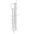
図8は、超極性電気外科用ペンシルの内部を示すための、超極性電気外科用ペンシル800のハンドピース部分の側部を取り除いて示した、本発明のアルゴンビーム機能を有する超極性電気外科用ペンシル800の例示的な実施形態の側面斜視図である。アルゴンビーム機能を有する超極性電気外科用ペンシル800は、第1の端部804および第2の端部806を有するハンドピース部材802と、ハンドピース部材802の第1の端部804内に配置された超極性電気外科用ブレード810とを含む。超極性電気外科用ブレード810は、対向する平坦側部814、狭く細長い頂部816、および鋭利な切断端818を有する非導電性ブレード812と、ならびに非導電性ブレード812の対向する平坦側部814のそれぞれに配置されたアクティブ接点820およびリターン接点822の両方とを含む。第1の非導電性中空管状部材832は、非導電性ブレード812に配置され、非導電性ブレード812の一方の対向する平坦側部814のアクティブ接点820の少なくとも一部、および非導電性ブレード812の他方の対向する平坦側部814のリターン接点822の少なくとも一部を覆うようにする。アルゴンビーム機能を有する超極性電気外科用ペンシルは、ハンドピース部材802内に含まれ、第1の非導電性中空管状部材832に接続された第2の非導電性中空管状部材838、およびハンドピース部材802内に配置されて、第1および第2の非導電性中空管状部材832、838にガスを供給するために、第2の非導電性中空管状部材838に接続されている非導電性管840をさらに含む。ワイヤ842はアクティブ接点820とリターン接点822とを回路基板844に接続し、回路基板844はひいては電源コード846を介して電源に接続される。ハンドピース部材802の選択ボタン848は、切断および/または凝固を作動させるために使用される。ハンドピース部材は、非導電性ブレード812の鋭利な切断端818から煙および/またはデブリを排出するためのチャネル850を含むことができ、また、アルゴンビーム機能を有する超極性電気外科用ペンシル800は、回転/旋回部材852を含み得る。これは、ハンドピース部材802の第2の端部806に接続させて、煙を排出するための真空を有するアルゴンビーム機能を有する超極性電気外科用ペンシル800を操作するときの吸引管の引っ張りおよびねじれを軽減する。アルゴンビーム機能を有する超極性電気外科用ブレードアセンブリの前述の実施形態のいずれかは、超極性電気外科用ブレードの対向する側部に位置するアクティブ接点およびリターン接点の諸部分にわたって配置された第1の非導電性中空管状部材のみを有する超極性電気外科用ブレードアセンブリを含む、本発明のアルゴンビーム機能を有する超極性電気外科用ペンシルと共に使用され得る。
FIG. 8 shows the superpolar electrosurgical pencil with argon beam capability of the present invention with the side of the handpiece portion of a superpolar electrosurgical pencil 800 removed to show the interior of the hyperpolar electrosurgical pencil. 8 is a side perspective view of an exemplary embodiment of pencil 800. FIG. A superpolar electrosurgical pencil 800 with argon beam capability is disposed within a handpiece member 802 having a
図9は、電気外科用ペンシルの内部要素を示すための、ハンドピースと中空伸縮部材とが接続されておらず、ハンドピースおよび中空伸縮部材の側部が取り除かれて示されている、本発明のアルゴンビーム機能を有する超極性伸縮電気外科用ペンシル100の例示的な実施形態の斜視図である。アルゴンビーム機能を有する超極性伸縮電気外科用ペンシル100は、第1および第2の端部116、118を有するチャネル114を有するハンドピース部材112、チャネル114内に収容された第1の導電性中空管120、チャネル114内に収容された第2の導電性中空管122、第1および第2の端部134、136を有する中空伸縮部材132、ここで第2の端部136はハンドピース部材112内に収容されている、第1の導電性中空管120よりも小さい直径を有し、中空伸縮部材132および第1の導電性中空管120の少なくとも一部内に収容されている第3の導電性中空
管140、中空伸縮部材132および第2の導電性中空管122の少なくとも一部内に含まれる導電性円筒形部材142、および中空伸縮部材132の第1の端部134内に配置された超極性電気外科用ブレード200を含む。超極性電気外科用ブレード200は、対向する平坦側部214と、鋭利な切断端218とを有する非導電性ブレード212、および非導電性ブレード212の対向する平坦側部214のそれぞれに配置されたアクティブ接点220とリターン接点222の両方を含み、ここで、アクティブ接点220が第3の導電性中空管132に接続され、リターン接点222が導電性円筒形部材142に接続されている。さらに、非導電性中空管状部材332は、超極性電気外科用ブレード200に配置され、非導電性ブレード212の一方の対向する平坦側部214のアクティブ接点220の少なくとも一部と、非導電性ブレード212の他方の対向する平坦側部214のリターン接点222の少なくとも一部とを覆う。第2の非導電性中空管状部材338もまた、非導電性中空管状部材332に隣接してこれと接続するように、超極性電気外科用ブレード200に配置してもよい。超極性電気外科用ブレード200に配置されたときに非導電性中空管状部材332を支えるために、非導電性シェルフ支持体226を非導電性ブレード212に含めることができる。
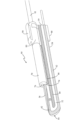
FIG. 9 shows the handpiece and hollow telescoping member unconnected and with side portions of the handpiece and hollow telescoping member removed to show the internal elements of the electrosurgical pencil of the present invention; 1 is a perspective view of an exemplary embodiment of a superpolar stretching
超極性電気外科用ブレード200および非導電性中空管状部材332(および、同様に含まれる場合は第2の非導電性管状部材338)も一緒になって、図10~図12を参照してさらに詳細に説明するアルゴンビーム機能を有する超極性電気外科用ブレードアセンブリ300を形成する。さらに、アルゴンビーム機能を有する超極性電気外科用ブレードアセンブリ300の例示的な実施形態は、係属番号62/362,873を有する仮特許出願、および係属番号15/648,553を有するその関連実用特許出願にも記載されている。両方とも参照によりその全体が本明細書に組み込まれる。
Superpolar electrosurgical blade 200 and non-conducting hollow tubular member 332 (and second non-conducting
アルゴンビーム機能を有する超極性伸縮電気外科用ペンシル100はまた、第1の導電性中空管120および第2の中空導電性管122をハンドピース部材122のチャネル114内に保持するための少なくとも1つの支持部材150を含み得る。アルゴンビーム機能を有する超極性伸縮電気外科用ペンシル100はまた、第3の導電性中空管140および導電性円筒形部材142を中空伸縮部材132内に保持するための少なくとも1つの支持部材160を含み得る。
Superpolar telescoping
アルゴンビーム機能を有する超極性伸縮電気外科用ペンシル100は、煙および/またはデブリを排出するための真空がそれに取り付けられたとき、操作時に超極性伸縮電気外科用ペンシル100の端部への引っ張りを避け、超極性伸縮電気外科用ペンシル100の操縦を容易にするための、ハンドピース部材112の第2の端部118に接続された回転/旋回部材170をさらに含み得る。加えて、アルゴンビーム機能を有する超極性電気外科用ブレードアセンブリ300を中空伸縮部材132の第1の端部134内に配置して、非導電性中空管状部材332が、中空伸縮部材132の第1の端部134の外側に配置されるようにする。さらにまた、ハンドピース部材112内に収容された第1の導電性中空管120および第2の導電性中空管122は、それらの外面に絶縁体を有してもよい。
A superpolar telescopic
図14は、本発明のアルゴンビーム機能を有する超極性伸縮電気外科用ペンシル100の一部を構成するアクティブ接点およびリターン接点と共に示される、図9~図13に示される超極性電気外科用ブレードの部分的な斜視図である。図14は、図1と同一であるが異なる参照番号で示されて、図9~図13を参照して説明した超極性伸縮電気外科用ペンシルの実施形態に対応している。超極性電気外科用ブレード200は、対向する平坦側部214と、狭く細長い頂部216と、鋭利な切断端218と、対向する非切断端(ブレードの一部分の図であるために図示せず)とを有する非導電性ブレード212を含む。超極性電気外科用ブレード200はまた、非導電性ブレード212の対向する平坦側部214のそれぞれに配置されたアクティブ電極220とリターン電極222の両方を含む。非
導電性ブレード212の狭く細長い頂部216に隣接して位置するアクティブ電極220およびリターン電極222の部分224は、狭く細長い頂部216から外側下方に突出する非導電性ブレード212の上側部分230に存在する。超極性電気外科用ブレード200はまた、図10~図12を参照して示され説明されたアルゴンビーム機能を有する電気外科用ブレードアセンブリ300の一部を含む非導電性中空管状部材332を支持するための非導電性シェルフ支持体226を含み得る。
FIG. 14 is the superpolar electrosurgical blade shown in FIGS. 9-13 shown with the active and return contacts forming part of the superpolar telescopic
図13は、図9~図12および図14に示されている超極性電気外科用ブレード200の非導電性ブレード部分212の形状を示す部分的な斜視図である。非導電性ブレード212は、対向する平坦側部214と、狭く細長い頂部216と、鋭利な切断端218と、対向する非切断端(ブレードの一部分の図であるために図示せず)とを含む。非導電性ブレード212の上側部分230は、狭く細長い頂部216から外側下方に、また非導電性ブレード212の対向する平坦側部214の中に突出している。非導電性ブレード212はまた、アルゴンビーム機能を有する電気外科用ブレードアセンブリ300の一部を構成する非導電性中空管状部材332を支持するための非導電性シェルフ支持体226を含み得る。
13 is a partial perspective view showing the shape of the
図10は、超極性電気外科用ブレードアセンブリ300が超極性伸縮電気外科用ペンシル100の内部構成要素にどのように接続されるかを示すため、図9に示された超極性伸縮電気外科用ペンシル100に含まれる超極性電気外科用ブレードアセンブリ300、ならびに図9に示された超極性伸縮電気外科用ペンシル100の第3の導電性中空管140および導電性円筒形部材142の例示的な実施形態の部分的な分解斜視図である。第1の非導電性中空管状部材332は、非導電性ブレード212の狭く細長い頂部216に嵌合するスロット334を有し、それにより非導電性中空管状部材332は、非導電性ブレード212の一方の対向する平坦側部214のアクティブ電極220の少なくとも一部、および非導電性ブレード212の他方の対向する平坦側部214のリターン電極222の少なくとも一部を覆う。非導電性中空管状部材332は、非導電性中空管状部材332の各端部のスロット334の上方に位置する開口部336をさらに含む。これにより、非導電性中空管状部材332に供給されたガスが、非導電性中空管状部材332内に含まれるアクティブ電極およびリターン電極の諸部分と接触するときにイオン化でき、次いでイオン化ガスが、超極性電気外科用ブレード200の鋭利な切断端218の最も近い位置に配置されている、非導電性中空管状部材332の開口部336を通して放出される。
FIG. 10 illustrates how superpolar stretchable
第2の非導電性中空管状部材338は、第1の非導電性中空管状部材332に隣接する非導電性ブレード212の狭く細長い頂部216にわたって配置されてもよいが、リターン電極/接点222のいかなる部分も覆わない。しかし、第2の非導電性中空管状部材338は、非導電性ブレード212の非切断端の近くに配置されているアクティブ電極/接点220の一部を覆ってもよい。第1の非導電性中空管状部材332は、超極性電気外科用ブレード200の非導電性シェルフ支持体226上に位置することができ、第1の非導電性中空管状部材332は交換可能/置換可能であり得る。あるいは、第1の非導電性中空管状部材332は、第2の非導電性中空管状部材338および/または非導電性シェルフ支持体226に恒久的に取り付けられてもよい。
A second non-conducting
超極性電気外科用ブレードアセンブリ300は、超極性伸縮電気外科用ペンシル100の中空伸縮部材132内に含まれる要素に接続される。より具体的には、超極性伸縮電気外科用ペンシル100の第3の導電性中空管140の一端が、超極性電気外科用ブレードアセンブリ300の第2の非導電性中空管状部材338に挿入されて接続され、また超極性電気外科用ペンシル100の導電性円筒形部材142の一端が、超極性電気外科用ブレードアセンブリ300の超極性電気外科用ブレード200の非切断端に位置するリターン電極/接点222に接続される。
Superpolar
図11は、超極性電気外科用ブレードアセンブリ300の非導電性中空管状部材336および超極性伸縮電気外科用ペンシル100の第3の導電性中空管140を伴わない、図10に示す超極性電気外科用ブレードアセンブリ300の例示的実施形態の上面図である。
FIG. 11 illustrates the superpolar electrical power shown in FIG. 10 without non-conductive
図12は、超極性電気外科用ブレード200の対向する側部に配置されているアクティブおよびリターン接点/電極を示すための、180度回転させて示した、図10に描写している、超極性伸縮電気外科用ペンシル100の超極性電気外科用ブレードアセンブリ300、第3の導電性中空管140、および導電性円筒形部材142の例示的実施形態の斜視図である。図10および図12に示すように、第1の非導電性中空管状部材332が超極性電気外科用ブレード200の狭く細長い頂部216の上に位置するとき、第1の非導電性中空管状部材332は、非導電性ブレード212の一方の対向する平坦側部214にあるリターン電極/接点222の一部(図10参照)、および非導電性ブレード212の他方の対向する平坦側部214にあるアクティブ電極/コンタクト220の一部(図12参照)を覆う。非導電性ブレード212および第1の非導電性中空管状部材332はそれぞれセラミック材料を含むことができる。第2の非導電性中空管状部材338もセラミック材料を含み得る。
FIG. 12 shows the superpolar electrode depicted in FIG. 10 rotated 180 degrees to show the active and return contacts/electrodes located on opposite sides of the superpolar electrosurgical blade 200 . 3A is a perspective view of an exemplary embodiment of superpolar
本発明の超極性伸縮電気外科用ペンシル100の例示的な一実施形態は、超極性電気外科用ブレードアセンブリ300の第2の非導電性中空管状部材338を含まなくてもよい。この実施形態では、非導電性中空管状部材332は長さがより長くなり、超極性電気外科用ブレード200の非切断端まで延在する。この実施形態では、超極性電気外科用ブレードアセンブリ300を超極性伸縮電気外科用ペンシル100の中空伸縮部材132内に含まれる要素に接続する際に、超極性伸縮電気外科用ペンシル100の第3の導電性中空管140の一端が、超極性電気外科用ブレードアセンブリ300の非導電性中空管状部材332に挿入されて接続され、また超極性電気外科用ペンシル100の導電性円筒形部材142の一端が、超極性電気外科用ブレードアセンブリ300の超極性電気外科用ブレード200の非切断端に位置するリターン電極/接点222に接続される。
An exemplary embodiment of the superpolar telescoping
図9に示す超極性伸縮電気外科用ペンシルの例示的な実施形態に戻ると、管179を通るガスの供給が第1の導電性中空管120に接続され、ガスは第1の導電性中空管120、第3の導電性中空管140を経て第2の非導電性管状部材338に移動し、非導電性管状部材332を通る。ガスは、非導電性中空管状部材332内に収容されたアクティブ電極220およびリターン電極222の諸部分と接触するとイオン化され、イオン化ガスは次に、超極性電気外科用ブレード200の鋭利な切断端218に最も近い位置にある、非導電性中空管状部材332の開口部336を通して放出される。ワイヤ180は、ハンドピース部材112内の回路基板(図示せず)に第1の導電性中空管120および第2の導電性中空管122を接続し、回路基板はひいては電源コード184を介して電源に接続される。ハンドピース部材112の選択ボタン188は、切断および/または凝固を作動させるために使用される。
Returning to the exemplary embodiment of the superpolar telescoping electrosurgical pencil shown in FIG. 9, a supply of gas through
本明細書における本発明の例示的な実施形態の上記の説明は、本発明の様々な例示的実施形態を示す。これらの例示的な実施形態およびモードは、当業者が本発明を実施することを可能にするために十分詳細に説明されて示されており、決して本発明の範囲、適用性、または構成を限定することを意図していない。むしろ、この開示は、例示的な実施態様およびモードの実施形態ならびに当業者に知られているか明白である任意の同等のモードまたは実施形態の両方を教示することを意図している。さらに、含まれるすべての例は、例示的な実施形態およびモードの非限定的な例示であり、それらも同様に、当業者に知られているか明らかである任意の同等のモードまたは実施形態に役立つ。 The foregoing descriptions of exemplary embodiments of the invention herein illustrate various exemplary embodiments of the invention. These exemplary embodiments and modes are described and shown in sufficient detail to enable those skilled in the art to practice the invention, and in no way limit the scope, applicability, or configuration of the invention. not intended to Rather, this disclosure is intended to teach both the exemplary implementations and mode embodiments and any equivalent modes or embodiments known or apparent to those of ordinary skill in the art. Furthermore, all included examples are non-limiting illustrations of exemplary embodiments and modes, which likewise lend themselves to any equivalent modes or embodiments known or apparent to those skilled in the art. .
特に列挙されていないものに加えて、本発明の実施において使用される構造、配置、用途、割合、要素、材料、または構成要素の他の組み合わせおよび/または修正は、変更することができ、さもなければ本発明の範囲から逸脱することなく、特定の環境、製造上の仕様、設計パラメータ、または他の動作要件に特に適合させることができ、また本開示に含まれることが意図されている。 Other combinations and/or modifications of the structure, arrangement, application, proportions, elements, materials, or components used in the practice of the invention, in addition to those not specifically recited, may be changed or Otherwise, it may be specifically adapted to a particular environment, manufacturing specifications, design parameters, or other operating requirements without departing from the scope of the present invention and is intended to be covered by this disclosure.
特に明記しない限り、明細書および特許請求の範囲における語句に、一般に認められている一般的な意味、または当業者によって使用される通常の慣用の意味を与えることを、出願人は意図している。それらの意味が異なる場合、明細書および特許請求の範囲における語句は、可能な限り広く一般的な意味を与えられるべきである。他のいずれかの特別な意味をいずれかの語句に対して意図している場合、本明細書は特別な意味について明確に述べて定義している。 Unless otherwise specified, applicants intend that words and phrases in the specification and claims are to be given their generally accepted general meanings or ordinary and customary meanings used by those of ordinary skill in the art. . Where their meanings differ, words and phrases in the specification and claims should be given the broadest general meaning possible. If any other special meaning is intended for any term, the specification expressly states and defines the special meaning.
Claims (20)
前記超極性外科用ブレードアセンブリは、
板状の非導電性ブレードであって、それぞれ長さ方向に垂直な厚さ方向において前記非導電性ブレードの両方の端に配置された第1および第2の対向する平坦側部、前記長さ方向において前記非導電性ブレードの一方の端に配置された鋭利な切断端、および前記長さ方向において前記非導電性ブレードの他方の端に配置されて前記切断端に対向する非切断端を有する、非導電性ブレードと、
前記非導電性ブレードの前記対向する平坦側部のそれぞれに配置されたアクティブ接点とリターン接点の両方と、
前記非導電性ブレードに配置される非導電性中空管状部材であって、前記非導電性ブレードの一方の対向する平坦側部のアクティブ接点の少なくとも一部分を覆い、前記非導電性ブレードの前記他方の対向する平坦側部のリターン接点の少なくとも一部分を覆うようにする、非導電性中空管状部材と
を含む、超極性電気外科装置。 A hyperpolar electrosurgical device capable of utilizing a bipolar electrosurgical blade assembly to use monopolar energy in a bipolar mode for cutting and coagulation thereby forming a hyperpolar electrosurgical blade assembly. hand,
The superpolar surgical blade assembly comprises:
a plate-like non-conductive blade, first and second opposed flat sides disposed at opposite ends of said non-conductive blade in a thickness direction each perpendicular to the length, said length ; a sharp cutting edge located at one end of the non-conductive blade in the direction and a non-cutting edge located at the other end of the non-conductive blade in the length direction opposite the cutting edge , a non-conductive blade, and
both an active contact and a return contact located on each of said opposed planar sides of said non-conductive blade;
A non-conductive hollow tubular member disposed on the non-conductive blade covering at least a portion of the active contact on one opposite flat side of the non-conductive blade and the other of the non-conductive blade. a non-conductive hollow tubular member overlying at least a portion of the return contact on opposite flat sides of the hyperpolar electrosurgical device.
に前記非導電性ブレードに接続された非導電性支持部材をさらに備える、請求項1に記載の超極性電気外科装置。 The hyperpolar electrosurgical apparatus of claim 1, further comprising a non-conductive support member connected to said non-conductive blade for retaining said hyperpolar electrosurgical blade assembly within an electrosurgical handpiece.
前記ハンドピース部材内に配置され、前記非導電性中空管状部材に接続されてガスを前記非導電性中空管状部材に供給するための非導電性管と
をさらに備える、請求項1に記載の超極性電気外科装置。 a handpiece member having a first end and a second end, wherein the superpolar electrosurgical blade assembly is disposed within the first end of the handpiece member; ,
3. The ultra-high-pressure device of claim 1, further comprising: a non-conductive tube disposed within said handpiece member and connected to said non-conductive hollow tubular member for supplying gas to said non-conductive hollow tubular member. Polar electrosurgical device.
前記チャネル内に含まれる第1の導電性中空管と、
前記チャネル内に含まれる第2の導電性中空管と、
第1の端部と第2の端部とを有する中空伸縮部材であって、前記中空伸縮部材の前記第2の端部が前記ハンドピース部材の前記第1の端部内に収容され、前記超極性電気外科用ブレードアセンブリが前記中空伸縮部材の前記第1の端部内に配置される中空伸縮部材と、
前記第1の導電性中空管よりも小さい直径を有する第3の導電性中空管であって、前記中空伸縮部材と前記第1の導電性中空管の少なくとも一部との中に含まれる第3の導電性中空管と、
前記中空伸縮部材と前記第2の導電性中空管の少なくとも一部との中に含まれる導電性円筒形部材であって、前記超極性電気外科用ブレードアセンブリの前記アクティブ接点と、前記超極性電気外科用ブレードアセンブリの前記非導電性中空管状部材が前記第3の導電性中空管に接続され、前記超極性電気外科用ブレードアセンブリの前記リターン接点が前記導電性円筒形部材に接続される導電性円筒形部材と、
をさらに備える、請求項1に記載の超極性電気外科装置。 a handpiece member having a channel having a first end and a second end;
a first conductive hollow tube contained within said channel;
a second conductive hollow tube contained within said channel;
A hollow telescoping member having a first end and a second end, the second end of the hollow telescoping member being received within the first end of the handpiece member, and a hollow telescoping member having a polarized electrosurgical blade assembly disposed within said first end of said hollow telescoping member;
a third conductive hollow tube having a smaller diameter than the first conductive hollow tube, the third conductive hollow tube being contained within the hollow telescoping member and at least a portion of the first conductive hollow tube; a third conductive hollow tube,
an electrically conductive cylindrical member contained within the hollow telescoping member and at least a portion of the second electrically conductive hollow tube, wherein the active contact of the superpolar electrosurgical blade assembly and the superpolar The non-conductive hollow tubular member of the electrosurgical blade assembly is connected to the third conductive hollow tube and the return contact of the superpolar electrosurgical blade assembly is connected to the conductive cylindrical member. an electrically conductive cylindrical member;
The hyperpolar electrosurgical device of claim 1, further comprising:
Priority Applications (1)
| Application Number | Priority Date | Filing Date | Title |
|---|---|---|---|
| JP2022085815A JP2022119896A (en) | 2016-07-15 | 2022-05-26 | Ultrapolar electrosurgery blade assembly and ultrapolar electrosurgery pencil with argon beam capability |
Applications Claiming Priority (5)
| Application Number | Priority Date | Filing Date | Title |
|---|---|---|---|
| US201662362873P | 2016-07-15 | 2016-07-15 | |
| US201662362968P | 2016-07-15 | 2016-07-15 | |
| US62/362,968 | 2016-07-15 | ||
| US62/362,873 | 2016-07-15 | ||
| PCT/US2017/042144 WO2018013926A1 (en) | 2016-07-15 | 2017-07-14 | Ultrapolar electrosurgery blade assembly and ultrapolar electrosurgery pencils with argon beam capability |
Related Child Applications (1)
| Application Number | Title | Priority Date | Filing Date |
|---|---|---|---|
| JP2022085815A Division JP2022119896A (en) | 2016-07-15 | 2022-05-26 | Ultrapolar electrosurgery blade assembly and ultrapolar electrosurgery pencil with argon beam capability |
Publications (4)
| Publication Number | Publication Date |
|---|---|
| JP2019522547A JP2019522547A (en) | 2019-08-15 |
| JP2019522547A5 JP2019522547A5 (en) | 2020-08-13 |
| JP7084044B2 JP7084044B2 (en) | 2022-06-14 |
| JP7084044B6 true JP7084044B6 (en) | 2023-08-18 |
Family
ID=60953341
Family Applications (2)
| Application Number | Title | Priority Date | Filing Date |
|---|---|---|---|
| JP2019501942A Active JP7084044B6 (en) | 2016-07-15 | 2017-07-14 | Superpolar electrosurgical blade assembly and superpolar electrosurgical pencil with argon beam capability |
| JP2022085815A Pending JP2022119896A (en) | 2016-07-15 | 2022-05-26 | Ultrapolar electrosurgery blade assembly and ultrapolar electrosurgery pencil with argon beam capability |
Family Applications After (1)
| Application Number | Title | Priority Date | Filing Date |
|---|---|---|---|
| JP2022085815A Pending JP2022119896A (en) | 2016-07-15 | 2022-05-26 | Ultrapolar electrosurgery blade assembly and ultrapolar electrosurgery pencil with argon beam capability |
Country Status (7)
| Country | Link |
|---|---|
| US (4) | US10512500B2 (en) |
| JP (2) | JP7084044B6 (en) |
| CN (1) | CN109862841B (en) |
| AU (1) | AU2017294769B2 (en) |
| CA (1) | CA3030964A1 (en) |
| DE (1) | DE112017003593T5 (en) |
| WO (1) | WO2018013926A1 (en) |
Families Citing this family (4)
| Publication number | Priority date | Publication date | Assignee | Title |
|---|---|---|---|---|
| US10512500B2 (en) * | 2016-07-15 | 2019-12-24 | I.C. Medical, Inc. | Ultrapolar telescopic electrosurgery pencil with argon beam capability |
| AU2017338912B2 (en) * | 2016-10-05 | 2022-12-15 | I.C. Medical, Inc. | Ultrapolar electrosurgery blade and ultrapolar electrosurgery pencil and telescopic electrosurgery pencil for use in esu monopolar and bipolar modes |
| CN116942299A (en) * | 2017-03-01 | 2023-10-27 | I.C.医疗股份有限公司 | Super-polar telescopic and non-telescopic electrosurgical pencil and super-polar electrosurgical blade assembly with argon beam capability |
| KR101808565B1 (en) | 2017-07-11 | 2017-12-13 | 최경미 | Molded plate |
Citations (3)
| Publication number | Priority date | Publication date | Assignee | Title |
|---|---|---|---|---|
| JP2002529190A (en) | 1998-11-16 | 2002-09-10 | イアン コスメスク, | Multifunctional telescoping instrument and method therefor |
| US20130110108A1 (en) | 2011-10-28 | 2013-05-02 | Peak Surgical, Inc. | Single instrument electrosurgery apparatus and its method of use |
| US20160051313A1 (en) | 2014-08-22 | 2016-02-25 | Jerome Canady | Attachment for Electrosurgical System |
Family Cites Families (25)
| Publication number | Priority date | Publication date | Assignee | Title |
|---|---|---|---|---|
| US3987795A (en) * | 1974-08-28 | 1976-10-26 | Valleylab, Inc. | Electrosurgical devices having sesquipolar electrode structures incorporated therein |
| EP0148250A1 (en) | 1983-07-06 | 1985-07-17 | STASZ, Peter | Electro cautery surgical blade |
| US5013312A (en) * | 1990-03-19 | 1991-05-07 | Everest Medical Corporation | Bipolar scalpel for harvesting internal mammary artery |
| US5256138A (en) | 1990-10-04 | 1993-10-26 | The Birtcher Corporation | Electrosurgical handpiece incorporating blade and conductive gas functionality |
| US5281216A (en) | 1992-03-31 | 1994-01-25 | Valleylab, Inc. | Electrosurgical bipolar treating apparatus |
| US5693044A (en) * | 1992-12-11 | 1997-12-02 | Cosmescu; Ioan | Telescopic surgical device and method therefor |
| US5991650A (en) * | 1993-10-15 | 1999-11-23 | Ep Technologies, Inc. | Surface coatings for catheters, direct contacting diagnostic and therapeutic devices |
| US7112199B2 (en) * | 1996-09-20 | 2006-09-26 | Ioan Cosmescu | Multifunctional telescopic monopolar/bipolar surgical device and method therefore |
| US6355034B2 (en) * | 1996-09-20 | 2002-03-12 | Ioan Cosmescu | Multifunctional telescopic monopolar/bipolar surgical device and method therefor |
| DE19915061A1 (en) * | 1999-04-01 | 2000-10-26 | Erbe Elektromedizin | Surgical instrument |
| US20040034339A1 (en) * | 2002-08-16 | 2004-02-19 | The Regents Of The University Of California | Device for improved visualization of operative sites during surgery |
| DE10240847B4 (en) * | 2002-09-04 | 2011-07-28 | Erbe Elektromedizin GmbH, 72072 | Applicator for an electrosurgical instrument |
| DE10351370B4 (en) * | 2003-11-04 | 2011-08-11 | Erbe Elektromedizin GmbH, 72072 | Instrument for plasma coagulation |
| GB2415140A (en) * | 2004-06-18 | 2005-12-21 | Gyrus Medical Ltd | A surgical instrument |
| WO2006086356A2 (en) * | 2005-02-07 | 2006-08-17 | Jerome Canady | Apc dual mode theraputic balloon dilator |
| ATE529734T1 (en) * | 2005-04-06 | 2011-11-15 | Harvard College | MOLECULAR CHARACTERIZATION WITH CARBON NANOTUBE CONTROL |
| US9144453B2 (en) * | 2010-11-08 | 2015-09-29 | Bovie Medical Corporation | Multi-mode electrosurgical apparatus |
| US9757181B2 (en) * | 2012-06-12 | 2017-09-12 | Covidien Lp | Electrosurgical dissector with thermal management |
| GB2503673A (en) * | 2012-07-03 | 2014-01-08 | Creo Medical Ltd | Electrosurgical device with convex under surface |
| WO2014138366A1 (en) | 2013-03-06 | 2014-09-12 | I.C. Medical, Inc. | Argon beam assisted electrosurgery pencil with smoke evacuation |
| GB201418474D0 (en) * | 2014-10-17 | 2014-12-03 | Creo Medical Ltd | Electrosurgical apparatus |
| US20160317209A1 (en) * | 2015-04-28 | 2016-11-03 | I.C. Medical, Inc. | Electrosurgery blades with argon beam capability |
| CN204765908U (en) * | 2015-06-15 | 2015-11-18 | 山东玉华电气有限公司 | Monopole electrode that congeals APC work is restrainted to control argon |
| EP3141204B1 (en) * | 2015-09-10 | 2021-07-28 | Erbe Elektromedizin GmbH | Ablation system for the large-scale surface coagulation of biological tissues |
| US10512500B2 (en) * | 2016-07-15 | 2019-12-24 | I.C. Medical, Inc. | Ultrapolar telescopic electrosurgery pencil with argon beam capability |
-
2017
- 2017-07-13 US US15/649,429 patent/US10512500B2/en active Active
- 2017-07-13 US US15/648,553 patent/US10507053B2/en active Active
- 2017-07-14 CA CA3030964A patent/CA3030964A1/en active Pending
- 2017-07-14 AU AU2017294769A patent/AU2017294769B2/en active Active
- 2017-07-14 CN CN201780043913.3A patent/CN109862841B/en active Active
- 2017-07-14 JP JP2019501942A patent/JP7084044B6/en active Active
- 2017-07-14 WO PCT/US2017/042144 patent/WO2018013926A1/en active Application Filing
- 2017-07-14 DE DE112017003593.7T patent/DE112017003593T5/en active Pending
-
2019
- 2019-12-16 US US16/715,962 patent/US11540870B2/en active Active
- 2019-12-20 US US16/722,560 patent/US11419664B2/en active Active
-
2022
- 2022-05-26 JP JP2022085815A patent/JP2022119896A/en active Pending
Patent Citations (3)
| Publication number | Priority date | Publication date | Assignee | Title |
|---|---|---|---|---|
| JP2002529190A (en) | 1998-11-16 | 2002-09-10 | イアン コスメスク, | Multifunctional telescoping instrument and method therefor |
| US20130110108A1 (en) | 2011-10-28 | 2013-05-02 | Peak Surgical, Inc. | Single instrument electrosurgery apparatus and its method of use |
| US20160051313A1 (en) | 2014-08-22 | 2016-02-25 | Jerome Canady | Attachment for Electrosurgical System |
Also Published As
| Publication number | Publication date |
|---|---|
| CA3030964A1 (en) | 2018-01-18 |
| AU2017294769B2 (en) | 2022-07-28 |
| US10507053B2 (en) | 2019-12-17 |
| US20200121383A1 (en) | 2020-04-23 |
| US10512500B2 (en) | 2019-12-24 |
| US20180092684A1 (en) | 2018-04-05 |
| JP2022119896A (en) | 2022-08-17 |
| WO2018013926A1 (en) | 2018-01-18 |
| JP2019522547A (en) | 2019-08-15 |
| DE112017003593T5 (en) | 2019-05-02 |
| US20180092683A1 (en) | 2018-04-05 |
| US11419664B2 (en) | 2022-08-23 |
| JP7084044B2 (en) | 2022-06-14 |
| US20200113618A1 (en) | 2020-04-16 |
| US11540870B2 (en) | 2023-01-03 |
| CN109862841B (en) | 2022-02-08 |
| AU2017294769A1 (en) | 2019-03-07 |
| CN109862841A (en) | 2019-06-07 |
Similar Documents
| Publication | Publication Date | Title |
|---|---|---|
| JP2022119896A (en) | Ultrapolar electrosurgery blade assembly and ultrapolar electrosurgery pencil with argon beam capability | |
| US20210290287A1 (en) | Ultrapolar electrosurgery blade assembly | |
| US20230135303A1 (en) | Ultrapolar telescopic electrosurgery pencil and ultrapolar electrosurgery blade | |
| US11103303B2 (en) | Ultrapolar telescopic electrosurgery pencil | |
| US20220338918A1 (en) | Ultrapolar electrosurgery blade and pencil for use in esu monopolar and bipolar modes | |
| JP2020508810A (en) | Monopolar electrosurgical pencil with argon beam function | |
| AU2017295251B2 (en) | Ultrapolar electrosurgery blade and ultrapolar electrosurgery pencils | |
| US20220409262A1 (en) | Ultrapolar electrosurgery blade and ultrapolar electrosurgery pencil |
Legal Events
| Date | Code | Title | Description |
|---|---|---|---|
| A521 | Request for written amendment filed |
Free format text: JAPANESE INTERMEDIATE CODE: A523 Effective date: 20190408 |
|
| A521 | Request for written amendment filed |
Free format text: JAPANESE INTERMEDIATE CODE: A523 Effective date: 20200706 |
|
| A621 | Written request for application examination |
Free format text: JAPANESE INTERMEDIATE CODE: A621 Effective date: 20200706 |
|
| A977 | Report on retrieval |
Free format text: JAPANESE INTERMEDIATE CODE: A971007 Effective date: 20210521 |
|
| A131 | Notification of reasons for refusal |
Free format text: JAPANESE INTERMEDIATE CODE: A131 Effective date: 20210525 |
|
| A601 | Written request for extension of time |
Free format text: JAPANESE INTERMEDIATE CODE: A601 Effective date: 20210825 |
|
| A601 | Written request for extension of time |
Free format text: JAPANESE INTERMEDIATE CODE: A601 Effective date: 20211025 |
|
| A521 | Request for written amendment filed |
Free format text: JAPANESE INTERMEDIATE CODE: A523 Effective date: 20211125 |
|
| TRDD | Decision of grant or rejection written | ||
| A01 | Written decision to grant a patent or to grant a registration (utility model) |
Free format text: JAPANESE INTERMEDIATE CODE: A01 Effective date: 20220426 |
|
| A61 | First payment of annual fees (during grant procedure) |
Free format text: JAPANESE INTERMEDIATE CODE: A61 Effective date: 20220526 |
|
| R150 | Certificate of patent or registration of utility model |
Ref document number: 7084044 Country of ref document: JP Free format text: JAPANESE INTERMEDIATE CODE: R150 |