JP7083664B2 - Receptacle module and medical equipment - Google Patents
Receptacle module and medical equipment Download PDFInfo
- Publication number
- JP7083664B2 JP7083664B2 JP2018039073A JP2018039073A JP7083664B2 JP 7083664 B2 JP7083664 B2 JP 7083664B2 JP 2018039073 A JP2018039073 A JP 2018039073A JP 2018039073 A JP2018039073 A JP 2018039073A JP 7083664 B2 JP7083664 B2 JP 7083664B2
- Authority
- JP
- Japan
- Prior art keywords
- receptacle
- substrate
- patient circuit
- patient
- circuit unit
- Prior art date
- Legal status (The legal status is an assumption and is not a legal conclusion. Google has not performed a legal analysis and makes no representation as to the accuracy of the status listed.)
- Active
Links
Images


Classifications
-
- A—HUMAN NECESSITIES
- A61—MEDICAL OR VETERINARY SCIENCE; HYGIENE
- A61B—DIAGNOSIS; SURGERY; IDENTIFICATION
- A61B1/00—Instruments for performing medical examinations of the interior of cavities or tubes of the body by visual or photographical inspection, e.g. endoscopes; Illuminating arrangements therefor
- A61B1/04—Instruments for performing medical examinations of the interior of cavities or tubes of the body by visual or photographical inspection, e.g. endoscopes; Illuminating arrangements therefor combined with photographic or television appliances
- A61B1/045—Control thereof
-
- A—HUMAN NECESSITIES
- A61—MEDICAL OR VETERINARY SCIENCE; HYGIENE
- A61B—DIAGNOSIS; SURGERY; IDENTIFICATION
- A61B1/00—Instruments for performing medical examinations of the interior of cavities or tubes of the body by visual or photographical inspection, e.g. endoscopes; Illuminating arrangements therefor
- A61B1/00112—Connection or coupling means
- A61B1/00114—Electrical cables in or with an endoscope
-
- H—ELECTRICITY
- H05—ELECTRIC TECHNIQUES NOT OTHERWISE PROVIDED FOR
- H05K—PRINTED CIRCUITS; CASINGS OR CONSTRUCTIONAL DETAILS OF ELECTRIC APPARATUS; MANUFACTURE OF ASSEMBLAGES OF ELECTRICAL COMPONENTS
- H05K9/00—Screening of apparatus or components against electric or magnetic fields
- H05K9/0007—Casings
- H05K9/002—Casings with localised screening
- H05K9/0022—Casings with localised screening of components mounted on printed circuit boards [PCB]
- H05K9/0024—Shield cases mounted on a PCB, e.g. cans or caps or conformal shields
-
- A—HUMAN NECESSITIES
- A61—MEDICAL OR VETERINARY SCIENCE; HYGIENE
- A61B—DIAGNOSIS; SURGERY; IDENTIFICATION
- A61B1/00—Instruments for performing medical examinations of the interior of cavities or tubes of the body by visual or photographical inspection, e.g. endoscopes; Illuminating arrangements therefor
- A61B1/00112—Connection or coupling means
- A61B1/00121—Connectors, fasteners and adapters, e.g. on the endoscope handle
-
- G—PHYSICS
- G06—COMPUTING; CALCULATING OR COUNTING
- G06F—ELECTRIC DIGITAL DATA PROCESSING
- G06F1/00—Details not covered by groups G06F3/00 - G06F13/00 and G06F21/00
- G06F1/16—Constructional details or arrangements
- G06F1/18—Packaging or power distribution
- G06F1/181—Enclosures
- G06F1/182—Enclosures with special features, e.g. for use in industrial environments; grounding or shielding against radio frequency interference [RFI] or electromagnetical interference [EMI]
Description
本発明は、レセプタクルモジュール及び医療機器に関する。 The present invention relates to a receptacle module and a medical device.
従来、被検体に接触または挿入される電子スコープ等の先端装置を備えた医療機器において、患者回路と2次回路とを電気的に絶縁した構成が知られている(例えば、特許文献1参照)。
患者回路は、通常、保護接地されていないフローティング回路として構成される。このため、患者回路自体がアンテナとして機能し、外部から当該患者回路へのノイズの混入、あるいは、当該患者回路から外部へのノイズの送信が行われ易いものである。このため、特許文献1に記載の医療機器(内視鏡撮像装置)では、先端装置を含む患者回路のうち、当該先端装置に導通する患者回路部をシールド部材(患者回路部シールドケース)にて覆っている。
Conventionally, in a medical device provided with an advanced device such as an electronic scope that is in contact with or inserted into a subject, a configuration in which a patient circuit and a secondary circuit are electrically insulated is known (see, for example, Patent Document 1). ..
The patient circuit is usually configured as a floating circuit that is not protectively grounded. Therefore, the patient circuit itself functions as an antenna, and it is easy for noise to be mixed into the patient circuit from the outside or to be transmitted from the patient circuit to the outside. Therefore, in the medical device (endoscopic imaging device) described in Patent Document 1, among the patient circuits including the advanced device, the patient circuit portion conducting to the advanced device is shielded by a shield member (patient circuit portion shield case). Covering.
図16及び図17は、従来の医療機器における課題を説明する図である。
ところで、電子スコープ等の先端装置のコネクタに着脱自在に接続されるレセプタクル131Eと、患者基板14Eとを纏めたレセプタクルモジュール12E,12Fを構成する場合には、例えば、図16及び図17に示した構成が考えられる。
図16に示したレセプタクルモジュール12Eは、レセプタクル基板13Eと、患者基板14Eと、シールド部材15Eとを備える。
レセプタクル基板13Eは、配線パターンが設けられ、当該配線パターンに導通するようにレセプタクル131Eが実装されたプリント基板である。
患者基板14Eは、配線パターンが設けられ、当該配線パターンに導通するように電子部品が実装されたプリント基板である。この患者基板14Eは、図16に示すように、レセプタクル基板13Eに対して直交する姿勢で配置される。また、患者基板14Eに設けられた配線パターンは、ハーネスHa(図16)を介してレセプタクル基板13Eに設けられた配線パターンに導通する。
そして、レセプタクル基板13Eに設けられた配線パターン、患者基板14Eに設けられた配線パターンや電子部品、及びハーネスHaは、先端装置を含む患者回路のうち、当該先端装置に導通する患者回路部として機能する。
16 and 17 are diagrams illustrating problems in conventional medical devices.
By the way, when the
The
The
The
The wiring pattern provided on the
シールド部材15Eは、導電性材料から構成され、全体略直方体形状を有し、一つの側面が開口した容器状に形成されている。また、シールド部材15Eにおいて、容器状の側面には、レセプタクル131Eを挿通するための開口部154(図16)が形成されている。そして、シールド部材15Eは、図16に示すように、開口部154にレセプタクル131Eが挿通された状態で、容器状の開口部分が患者基板14Eにおける配線パターンや電子部品が設けられた面に装着され、患者回路部を覆う。
しかしながら、図16に示した構成では、シールド部材15Eに開口部154を形成している。また、レセプタクルモジュール12Eの組立性を考慮すると、シールド部材15Eを2体等に分割する必要がある。このため、シールド部材15Eの構造が複雑化してしまう、という問題がある。
The
However, in the configuration shown in FIG. 16, an
そこで、シールド部材15Eの構造の簡素化を図るために、図17に示したレセプタクルモジュール12Fを採用することが考えられる。
レセプタクルモジュール12Fは、図17に示すように、レセプタクル基板13Eと、患者基板14Eと、第1,第2シールド部材15F1,15F2とを備える。
第1,第2シールド部材15F1,15F2は、導電性材料からそれぞれ構成され、全体略直方体形状をそれぞれ有し、一つの側面が開口した容器状にそれぞれ形成されている。そして、第1シールド部材15F1は、図17に示すように、開口部分がレセプタクル基板13Eにおけるレセプタクル131Eが実装された面とは反対側の面に装着され、当該レセプタクル基板13Eに設けられた配線パターン(患者回路部)を覆う。また、第2シールド部材15F2は、開口部分が患者基板14Eにおける配線パターンや電子部品が設けられた面に装着され、当該患者基板14Eに設けられた配線パターンや電子部品(患者回路部)を覆う。なお、レセプタクル基板13Eに設けられた配線パターンと、患者基板14Eに設けられた配線パターンとは、第1,第2シールド部材15F1,15F2にそれぞれ形成された開口部155,156(図17)に通されたハーネスHa(図17)を介して互いに導通する。
しかしながら、図17に示した構成では、ハーネスHaの一部は、第1,第2シールド部材15F1,15F2の外部に位置する。このため、第1,第2シールド部材15F1,15F2の外部に位置するハーネスHaの一部がアンテナとして機能し、外部から当該ハーネスHaの一部(患者回路部)へのノイズの混入、あるいは、当該ハーネスHaの一部(患者回路部)から外部へのノイズの送信が行われ易い。すなわち、シールド性が悪い、という問題がある。
Therefore, in order to simplify the structure of the
As shown in FIG. 17, the
The first and second shield members 15F1 and 15F2 are each made of a conductive material, have a substantially rectangular parallelepiped shape as a whole, and are formed in a container shape with one side surface open. Then, as shown in FIG. 17, the first shield member 15F1 has an opening portion mounted on a surface of the
However, in the configuration shown in FIG. 17, a part of the harness Ha is located outside the first and second shield members 15F1 and 15F2. Therefore, a part of the harness Ha located outside the first and second shield members 15F1 and 15F2 functions as an antenna, and noise is mixed into a part (patient circuit portion) of the harness Ha from the outside, or Noise is easily transmitted from a part of the harness Ha (patient circuit portion) to the outside. That is, there is a problem that the shielding property is poor.
本発明は、上記に鑑みてなされたものであって、構造の簡素化を図りつつ、シールド性を向上させることができるレセプタクルモジュール、及び医療機器を提供することを目的とする。 The present invention has been made in view of the above, and an object of the present invention is to provide a receptacle module and a medical device capable of improving the shielding property while simplifying the structure.
上述した課題を解決し、目的を達成するために、本発明に係るレセプタクルモジュールは、被検体に接触または挿入される先端装置のコネクタが着脱自在に接続されるレセプタクルモジュールであって、前記コネクタが着脱自在に接続されるレセプタクルが実装されたレセプタクル基板と、前記レセプタクルを介して前記先端装置に導通する患者回路部と、前記レセプタクル基板に対して前記レセプタクルが実装された面とは反対側の面に装着され、当該レセプタクルが実装された面とは反対側から前記患者回路部を覆う導電性のシールド部材と、前記レセプタクル基板及び前記シールド部材の間に配置され、前記レセプタクルが実装された面とは反対側から当該シールド部材に覆われる患者基板とを備え、前記患者回路部は、前記レセプタクル基板に設けられ、前記レセプタクルに導通する第1患者回路部と、前記患者基板に設けられ、前記第1患者回路部に導通する第2患者回路部とを備えることを特徴とする。 In order to solve the above-mentioned problems and achieve the object, the receptacle module according to the present invention is a receptacle module in which a connector of an advanced device to be contacted or inserted into a subject is detachably connected, and the connector is A receptacle board on which a receptacle to be detachably connected is mounted, a patient circuit portion that conducts to the advanced device via the receptacle, and a surface of the receptacle board opposite to the surface on which the receptacle is mounted. A conductive shield member that covers the patient circuit portion from the side opposite to the surface on which the receptacle is mounted, and a surface that is arranged between the receptacle substrate and the shield member and on which the receptacle is mounted. Is provided with a patient substrate covered with the shield member from the opposite side , the patient circuit unit is provided on the receptacle board, a first patient circuit unit conducting the receptacle, and the patient circuit board are provided on the patient substrate. It is characterized by including a second patient circuit section that conducts to one patient circuit section .
また、本発明に係るレセプタクルモジュールでは、上記発明において、前記レセプタクル基板及び前記患者基板は、互いに対向する姿勢で配置されることを特徴とする。 Further, in the receptacle module according to the present invention, in the above invention, the receptacle substrate and the patient substrate are arranged in a posture facing each other.
また、本発明に係るレセプタクルモジュールでは、上記発明において、前記患者回路部は、前記レセプタクル基板に設けられ、前記レセプタクルに導通する第1患者回路部を備え、前記レセプタクル基板には、前記第1患者回路部を囲み、当該第1患者回路部に対して電気的に絶縁されているとともに絶縁伝送部を介して接続された2次回路部が設けられ、前記シールド部材は、前記レセプタクル基板に装着されて前記2次回路部の基準電位に設定されることを特徴とする。 Further, in the receptacle module according to the present invention, in the above invention, the patient circuit unit is provided on the receptacle substrate and includes a first patient circuit unit conducting the receptacle, and the receptacle substrate is provided with the first patient. A secondary circuit section is provided which surrounds the circuit section and is electrically insulated from the first patient circuit section and connected via an insulated transmission section, and the shield member is mounted on the receptacle substrate. It is characterized in that it is set to the reference potential of the secondary circuit unit.
また、本発明に係るレセプタクルモジュールは、被検体に接触または挿入される先端装置のコネクタが着脱自在に接続されるレセプタクルモジュールであって、前記コネクタが着脱自在に接続されるレセプタクルが実装されたレセプタクル基板と、前記レセプタクルを介して前記先端装置に導通する患者回路部と、前記レセプタクル基板に対して前記レセプタクルが実装された面とは反対側の面に装着され、当該レセプタクルが実装された面とは反対側から前記患者回路部を覆う導電性のシールド部材とを備え、前記患者回路部は、前記レセプタクル基板に設けられ、前記レセプタクルに導通する第1患者回路部を備え、前記レセプタクル基板には、前記第1患者回路部を囲み、当該第1患者回路部に対して電気的に絶縁されているとともに絶縁伝送部を介して接続された2次回路部が設けられ、前記シールド部材は、前記レセプタクル基板に装着されて前記2次回路部の基準電位に設定されることを特徴とする。
また、本発明に係るレセプタクルモジュールでは、上記発明において、前記絶縁伝送部は、前記レセプタクルが実装された面とは反対側から前記シールド部材にて覆われることを特徴とする。
Further, the receptacle module according to the present invention is a receptacle module in which a connector of a tip device to be contacted or inserted into a subject is detachably connected, and a receptacle to which the connector is detachably connected is mounted. The receptacle board, the patient circuit portion conducting to the advanced device via the receptacle, and the surface on which the receptacle is mounted are mounted on the surface opposite to the surface on which the receptacle is mounted. A conductive shield member that covers the patient circuit portion from the opposite side is provided , and the patient circuit portion is provided on the receptacle substrate and includes a first patient circuit portion that conducts to the receptacle, and is provided on the receptacle substrate. Surrounds the first patient circuit section, and is provided with a secondary circuit section that is electrically insulated from the first patient circuit section and connected via an insulated transmission section. It is characterized in that it is mounted on the receptacle substrate and set to the reference potential of the secondary circuit unit .
Further, in the receptacle module according to the present invention, in the above invention, the insulated transmission unit is covered with the shield member from the side opposite to the surface on which the receptacle is mounted.
また、本発明に係るレセプタクルモジュールでは、上記発明において、前記レセプタクル基板には、導電性のシールドパターンが設けられ、前記患者回路部は、前記シールドパターン及び前記シールド部材にて囲まれることを特徴とする。 Further, in the receptacle module according to the present invention, in the above invention, the receptacle substrate is provided with a conductive shield pattern, and the patient circuit portion is surrounded by the shield pattern and the shield member. do.
また、本発明に係るレセプタクルモジュールは、被検体に接触または挿入される先端装置のコネクタが着脱自在に接続されるレセプタクルモジュールであって、前記コネクタが着脱自在に接続されるレセプタクルが実装されたレセプタクル基板と、前記レセプタクルを介して前記先端装置に導通する患者回路部と、前記レセプタクル基板に対して前記レセプタクルが実装された面とは反対側の面に装着され、当該レセプタクルが実装された面とは反対側から前記患者回路部を覆う導電性のシールド部材とを備え、前記レセプタクル基板には、導電性のシールドパターンが設けられ、前記患者回路部は、前記シールドパターン及び前記シールド部材にて囲まれることを特徴とする。
また、本発明に係るレセプタクルモジュールでは、上記発明において、前記シールド部材は、前記レセプタクル基板に設けられたベース部と、前記ベース部に装着されるシールドケースとを備えることを特徴とする。
Further, the receptacle module according to the present invention is a receptacle module in which a connector of a tip device to be contacted or inserted into a subject is detachably connected, and a receptacle to which the connector is detachably connected is mounted. A substrate, a patient circuit portion conducting to the advanced device via the receptacle, and a surface mounted on the surface of the receptacle substrate opposite to the surface on which the receptacle is mounted and on which the receptacle is mounted. Is provided with a conductive shield member that covers the patient circuit portion from the opposite side, the receptacle substrate is provided with a conductive shield pattern, and the patient circuit portion is surrounded by the shield pattern and the shield member. It is characterized by being
Further, in the receptacle module according to the present invention, in the above invention, the shield member includes a base portion provided on the receptacle substrate and a shield case mounted on the base portion.
また、本発明に係るレセプタクルモジュールは、被検体に接触または挿入される先端装置のコネクタが着脱自在に接続されるレセプタクルモジュールであって、前記コネクタが着脱自在に接続されるレセプタクルが実装されたレセプタクル基板と、前記レセプタクルを介して前記先端装置に導通する患者回路部と、前記レセプタクル基板に対して前記レセプタクルが実装された面とは反対側の面に装着され、当該レセプタクルが実装された面とは反対側から前記患者回路部を覆う導電性のシールド部材とを備え、前記シールド部材は、前記レセプタクル基板に設けられたベース部と、前記ベース部に装着されるシールドケースとを備えることを特徴とする。
また、本発明に係る医療機器は、被検体に接触または挿入される先端装置と、前記先端装置のコネクタが着脱自在に接続される、上述したレセプタクルモジュールとを備えることを特徴とする。
Further, the receptacle module according to the present invention is a receptacle module in which a connector of a tip device to be contacted or inserted into a subject is detachably connected, and a receptacle to which the connector is detachably connected is mounted. A substrate, a patient circuit portion conducting to the advanced device via the receptacle, and a surface mounted on the surface of the receptacle substrate opposite to the surface on which the receptacle is mounted and on which the receptacle is mounted. Is provided with a conductive shield member that covers the patient circuit portion from the opposite side, and the shield member includes a base portion provided on the receptacle substrate and a shield case mounted on the base portion. And.
Further, the medical device according to the present invention is characterized by including a tip device that comes into contact with or is inserted into a subject, and the above-mentioned receptacle module to which the connector of the tip device is detachably connected.
本発明に係るレセプタクルモジュールでは、レセプタクル基板に対してレセプタクルが実装された面とは反対側の面にシールド部材を装着し、当該レセプタクルが実装された面とは反対側から当該シールド部材にて患者回路部を覆う構造を採用している。
このため、シールド部材を2体等に分割する必要がなく、当該シールド部材の構造の簡素化を図ることができる。また、シールド部材にて患者回路部を覆うことにより、患者回路部の一部(ハーネス等の一部)がシールド部材の外部に位置することがなく、患者回路部のシールド性を向上させることができる。
したがって、本発明に係るレセプタクルモジュールによれば、構造の簡素化を図りつつ、シールド性を向上させることができる、という効果を奏する。
In the receptacle module according to the present invention, the shield member is mounted on the surface of the receptacle substrate opposite to the surface on which the receptacle is mounted, and the shield member is used from the side opposite to the surface on which the receptacle is mounted. A structure that covers the circuit section is adopted.
Therefore, it is not necessary to divide the shield member into two or the like, and the structure of the shield member can be simplified. Further, by covering the patient circuit portion with the shield member, a part of the patient circuit portion (a part of the harness or the like) is not located outside the shield member, and the shielding property of the patient circuit portion can be improved. can.
Therefore, according to the receptacle module according to the present invention, it is possible to improve the shielding property while simplifying the structure.
また、本発明に係る医療機器は、上述したレセプタクルモジュールを備えるため、上述したレセプタクルモジュールと同様の作用及び効果を奏する。 Further, since the medical device according to the present invention includes the above-mentioned receptacle module, it has the same operation and effect as the above-mentioned receptacle module.
以下に、図面を参照して、本発明を実施するための形態(以下、実施の形態)について説明する。なお、以下に説明する実施の形態によって本発明が限定されるものではない。さらに、図面の記載において、同一の部分には同一の符号を付している。 Hereinafter, embodiments for carrying out the present invention (hereinafter referred to as embodiments) will be described with reference to the drawings. The present invention is not limited to the embodiments described below. Further, in the description of the drawings, the same parts are designated by the same reference numerals.
〔内視鏡装置の概略構成〕
図1は、本実施の形態に係る内視鏡装置1の概略構成を示す図である。
内視鏡装置1は、本発明に係る医療機器に相当する。この内視鏡装置1は、医療分野において用いられ、生体内等の被検体を観察する装置である。この内視鏡装置1は、図1に示すように、挿入部2と、光源装置3と、ライトガイド4と、カメラヘッド5と、第1伝送ケーブル6と、表示装置7と、第2伝送ケーブル8と、制御装置9と、第3伝送ケーブル10とを備える。
[Rough configuration of endoscope device]
FIG. 1 is a diagram showing a schematic configuration of an endoscope device 1 according to the present embodiment.
The endoscope device 1 corresponds to the medical device according to the present invention. This endoscope device 1 is used in the medical field and is a device for observing a subject such as in a living body. As shown in FIG. 1, the endoscope device 1 includes an
本実施の形態では、挿入部2は、硬性内視鏡で構成されている。すなわち、挿入部2は、硬質または少なくとも一部が軟質で細長形状を有し、生体内に挿入される。この挿入部2内には、1または複数のレンズを用いて構成され、被写体像を集光する光学系が設けられている。
光源装置3は、ライトガイド4の一端が接続され、制御装置9による制御の下、当該ライトガイド4の一端に生体内を照明する照明光を供給する。
ライトガイド4は、一端が光源装置3に着脱自在に接続されるとともに、他端が挿入部2に着脱自在に接続される。そして、ライトガイド4は、光源装置3から供給された光を一端から他端に伝達し、挿入部2に供給する。挿入部2に供給された光は、当該挿入部2の先端から出射され、生体内に照射される。生体内に照射され、当該生体内で反射された光(被写体像)は、挿入部2内の光学系により集光される。
In the present embodiment, the
One end of the
One end of the
カメラヘッド5は、挿入部2の基端(接眼部2a(図1))に着脱自在に接続される。そして、カメラヘッド5は、制御装置9による制御の下、挿入部2にて集光された被写体像を撮像し、当該撮像による画像信号(RAW信号)を出力する。本実施の形態では、当該画像信号は、4K以上の画像信号である。
第1伝送ケーブル6は、両端にコネクタCN1,CN2を有し、一端のコネクタCN1(図1)が制御装置9に着脱自在に接続され、他端のコネクタCN2(図1)がカメラヘッド5に着脱自在に接続される。そして、第1伝送ケーブル6は、カメラヘッド5から出力される画像信号を制御装置9に伝送するとともに、制御装置9から出力される制御信号、同期信号、クロック、及び駆動用電力等をカメラヘッド5にそれぞれ伝送する。
なお、第1伝送ケーブル6を介したカメラヘッド5から制御装置9への画像信号の伝送は、当該画像信号を光信号で伝送してもよく、あるいは、電気信号で伝送しても構わない。第1伝送ケーブル6を介した制御装置9からカメラヘッド5への制御信号、同期信号、クロックの伝送も同様である。
以上説明した挿入部2、カメラヘッド5、及び第1伝送ケーブル6は、本発明に係る先端装置11(図1)に相当する。
The
The
The image signal may be transmitted from the
The
制御装置9は、CPU(Central Processing Unit)等を含んで構成され、光源装置3、カメラヘッド5、及び表示装置7の動作を統括的に制御する。
具体的に、制御装置9は、第1伝送ケーブル6を介してカメラヘッド5から取得した画像信号に対して所定の処理を施すことで映像信号を生成し、第2伝送ケーブル8を介して当該映像信号を表示装置7に出力する。そして、表示装置7は、当該映像信号に基づく画像を表示する。また、制御装置9は、第1,第3伝送ケーブル6,10を介して、カメラヘッド5や光源装置3に対して制御信号等を出力する。
以上説明した制御装置9は、先端装置11のコネクタCN1が着脱自在に接続されるレセプタクルモジュール12(図1)を備える。なお、レセプタクルモジュール12の詳細な構成については後述する。
第3伝送ケーブル10は、一端が光源装置3に着脱自在に接続され、他端が制御装置9に着脱自在に接続される。そして、第3伝送ケーブル10は、制御装置9からの制御信号を光源装置3に伝送する。
The
Specifically, the
The
One end of the
〔1次回路、2次回路、及び患者回路について〕
図2は、内視鏡装置1における1次回路100、2次回路200、及び患者回路300を説明する図である。
以上説明した内視鏡装置1には、図2に示すように、大きく分けて3つの回路(1次回路100、2次回路200、及び患者回路300)が設けられている。
1次回路100は、制御装置9内に設けられ、インレット101を介して商用電源に接続される。そして、1次回路100は、2次回路200及び患者回路300にそれぞれ電力供給を行う。
[About primary circuit, secondary circuit, and patient circuit]
FIG. 2 is a diagram illustrating a
As shown in FIG. 2, the endoscope device 1 described above is roughly divided into three circuits (
The
2次回路200は、制御装置9内に設けられ、例えば、カメラヘッド5から取得した画像信号に対して所定の処理を施す信号処理部(図示略)等を備える。この2次回路200には、1次回路100から第1絶縁トランスIT1(図2)を介して電力供給される。すなわち、1次回路100と2次回路200とは、電気的に絶縁されている。また、2次回路200は、保護接地されている。
患者回路300は、先端装置11が生体内に接触した際に当該生体自体がその回路の一部となる電気回路であって、先端装置11と制御装置9内とに設けられ、例えば、挿入部2にて集光された被写体像を撮像する撮像素子(図示略)等を備える。この患者回路300には、1次回路100から第2絶縁トランスIT2(図2)を介して電力供給される。すなわち、1次回路100と患者回路300とは、電気的に絶縁されている。また、患者回路300は、2次回路200に対しても電気的に絶縁されている。さらに、2次回路200と患者回路300とは、2次回路200に設けられた第1インピーダンス素子Im1と患者回路300に設けられた第2インピーダンス素子Im2とを介して絶縁デバイス400にて接続されている。
ここで、第1,第2インピーダンス素子Im1,Im2としては、コンデンサ、コイル、抵抗等を例示することができる。また、絶縁デバイス400としては、例えば、フォトカプラや高周波トランス等を例示することができる。そして、患者回路300及び2次回路200間では、絶縁デバイス400を介して画像信号、制御信号、同期信号、及びクロック等が伝送される。
The
The
Here, examples of the first and second impedance elements Im1 and Im2 include a capacitor, a coil, and a resistance. Further, as the insulating
〔レセプタクルモジュールの構成〕
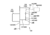
図3ないし図5は、レセプタクルモジュール12を示す図である。具体的に、図3は、レセプタクルモジュール12の全体斜視図である。図4は、図3に示したレセプタクルモジュール12の分解斜視図である。図5は、レセプタクルモジュール12を側方から見た図であって、シールド部材15の内部を模式的に示す図である。なお、図3に示す矢印は、レセプタクル131に対するコネクタCN1の挿入方向を示している。また、図5では、説明の便宜上、患者回路300及び絶縁デバイス400を実線で図示し、2次回路200を一点鎖線で図示するとともに、第2接続コネクタ135の図示を省略している。
レセプタクルモジュール12は、図3ないし図5に示すように、レセプタクル基板13と、患者基板14(図4,図5)と、シールド部材15とを備える。
[Receptacle module configuration]
3 to 5 are views showing the
As shown in FIGS. 3 to 5, the
図6は、レセプタクル基板13を示す図である。具体的に、図6は、レセプタクル131が実装された面13aとは反対側の面13b側からレセプタクル基板13を見た図である。
レセプタクル基板13は、ガラスエポキシ樹脂等の絶縁性材料で構成され、平面視矩形状の板体である。このレセプタクル基板13には、図6に示すように、第1の2次回路部132と、第1患者回路部133とが設けられている。本実施の形態では、レセプタクル基板13は、多層のプリント基板で構成されている。
FIG. 6 is a diagram showing a
The
第1の2次回路部132は、図6に示すように、レセプタクル基板13において、外縁に沿って延在する矩形枠状の領域に設けられている。この第1の2次回路部132は、信号線として機能する配線パターンや、グランド線として機能する配線パターン等で構成され、2次回路200の一部を構成する。すなわち、第1の2次回路部132は、本発明に係る2次回路部に相当する。また、第1の2次回路部132(主に当該第1の2次回路部132のグランド線)は、本発明に係るシールドパターンに相当する。
第1患者回路部133は、信号線として機能する配線パターンや、グランド線として機能する配線パターン等で構成され、レセプタクル基板13において、第1の2次回路部132よりも面13b側の層に設けられている。また、第1患者回路部133は、図6に示すように、第1の2次回路部132にて囲まれる中央の領域に設けられている。そして、第1患者回路部133は、患者回路300の一部を構成する。また、レセプタクル基板13における面13aには、第1患者回路部133に導通するようにレセプタクル131が実装されている。
そして、第1の2次回路部132及び第1患者回路部133は、電気的に絶縁された状態で、レセプタクル基板13に実装された絶縁デバイス400(図5)にて接続されている。
As shown in FIG. 6, the first
The first
The first
レセプタクル基板13の面13bには、図3、図4、または図6に示すように、第1~第4接続コネクタ134~137が実装されている。
第1接続コネクタ134は、図6に示すように、面13bに対して、第1の2次回路部132と平面的に重なる領域に実装され、当該第1の2次回路部132に導通する。この第1接続コネクタ134には、ハーネスHa(図5)等を介して、2次回路200のうち、第1の2次回路部132以外の他の2次回路が設けられた2次回路基板500(図5)が接続される。
第2接続コネクタ135は、図6に示すように、面13bに対して、第1の2次回路部132と平面的に重なる領域に実装され、レセプタクル基板13に設けられた銅箔等の配線パターン138を介して第1患者回路部133に導通する。なお、配線パターン138は、第1の2次回路部132よりも面13b側の層に設けられている。そして、第2接続コネクタ135には、ハーネス(図示略)等を介して、第2絶縁トランスIT2に接続される。すなわち、患者回路300には、第2接続コネクタ135を介して電力供給が行われる。
第3,第4接続コネクタ136,137は、図6に示すように、面13bに対して、第1患者回路部133と平面的に重なる領域にそれぞれ実装され、当該第1患者回路部133にそれぞれ導通する。そして、これら第3,第4接続コネクタ136,137は、BtoBコネクタで構成され、患者基板14に接続する。
As shown in FIGS. 3, 4, or 6, the first to
As shown in FIG. 6, the
As shown in FIG. 6, the
As shown in FIG. 6, the third and
以上説明したレセプタクル基板13において、第1の2次回路部132(2次回路200)と第1患者回路部133及び配線パターン138(患者回路300)とは、電気的に絶縁されていれば、異なる層に設けずに、同一の層に設けてもよい。また、レセプタクル基板13としては、多層のプリント基板ではなく、単層のプリント基板で構成しても構わない。
In the
患者基板14は、ガラスエポキシ樹脂等の絶縁性材料で構成され、レセプタクル基板13よりも平面サイズの小さい平面視矩形状の板体である。この患者基板14には、図4に示すように、第2患者回路部141が設けられている。
第2患者回路部141は、信号線として機能する配線パターン、グランド線として機能する配線パターン、及び当該各配線パターンに導通する電子部品等で構成され、患者回路300の一部を構成する。
以上説明した第1,第2患者回路部133,141は、本発明に係る患者回路部に相当する。
また、患者基板14には、BtoBコネクタでそれぞれ構成され、第3,第4接続コネクタ136,137とそれぞれ電気的に接続する第5,第6接続コネクタ142,143(図4)が実装されている。これら第5,第6接続コネクタ142,143は、第2患者回路部141と平面的に重なる領域にそれぞれ実装され、第2患者回路部141にそれぞれ導通する。すなわち、第1,第2患者回路部133,141は、第3~第6接続コネクタ136,137,142,143を介して互いに導通する。
以上のように、本実施の形態では、患者基板14は、レセプタクル基板13に対して、面13bに対向する姿勢で配置される。
The
The second
The first and second
Further, on the
As described above, in the present embodiment, the
シールド部材15は、導電性材料から構成され、全体略直方体形状を有し、一つの側面が開口した容器状に形成されている。そして、シールド部材15は、図3ないし図5に示すように、レセプタクル基板13の面13bに対して、当該開口部分が第1の2次回路部132と平面的に重なる領域に装着され(第1患者回路部133を囲むように装着され)、当該第1の2次回路部132のグランド線に導通する。すなわち、シールド部材15は、2次回路200の基準電位に設定される。そして、シールド部材15は、面13b側から第1,第2患者回路部133,141を覆う。また、シールド部材15は、レセプタクル基板13(第1の2次回路部132の主にグランド線(本発明に係るシールドパターン))との間で、第1,第2患者回路部133,141を囲む。この際、絶縁デバイス400、第3~第6接続コネクタ136,137,142,143も、レセプタクル基板13及びシールド部材15にて囲まれる。一方、第1,第2接続コネクタ134,135は、シールド部材15の外部に位置付けられる。
The
以上説明した本実施の形態によれば、以下の効果を奏する。
本実施の形態に係るレセプタクルモジュール12では、レセプタクル基板13の面13bに対してシールド部材15を装着し、当該シールド部材15にて第1,第2患者回路部133,141を覆う構造を採用している。
このため、シールド部材15を2体等に分割する必要がなく、当該シールド部材15の構造の簡素化を図ることができる。その結果、レセプタクルモジュール12の組立性を向上させ、製造コストを低減させることができる。また、シールド部材15の構造を簡素化することで、レセプタクルモジュール12の小型化及び軽量化も図ることができる。
特に、本発明に係る患者回路部として、レセプタクル基板13に設けた第1患者回路部133と、患者基板14に設けた第2患者回路部141との2つに分離している。このため、例えば、レセプタクル基板13に全ての患者回路部を設けた構成と比較して、レセプタクル基板13や患者基板14の基板単体のサイズを小さくすることができる。
According to the present embodiment described above, the following effects are obtained.
In the
Therefore, it is not necessary to divide the
In particular, the patient circuit section according to the present invention is separated into two, a first
また、本実施の形態に係るレセプタクルモジュール12では、シールド部材15は、2次回路200の基準電位に設定されている。
このため、シールド部材15は、保護接地された2次回路200の基準電位に設定されるため、第1,第2患者回路部133,141を安定にシールド(電磁遮蔽)することができる。
Further, in the
Therefore, since the
また、本実施の形態に係るレセプタクルモジュール12では、第1の2次回路部132(主に当該第1の2次回路部132のグランド線)を本発明に係るシールドパターンとして機能させている。
このため、シールド部材15及び第1の2次回路部132(主に当該第1の2次回路部132のグランド線)にて第1,第2患者回路部133,141を囲み、第1,第2患者回路部133,141のシールド性をさらに向上させることができる。
Further, in the
Therefore, the
(その他の実施の形態)
ここまで、本発明を実施するための形態を説明してきたが、本発明は上述した実施の形態によってのみ限定されるべきものではない。
図7は、本実施の形態の変形例1を示す図である。具体的に、図7は、図5に対応した図である。なお、図7では、図5と同様に、患者回路300及び絶縁デバイス400を実線で図示し、2次回路200を一点鎖線で図示するとともに、第2接続コネクタ135の図示を省略している。
上述した実施の形態において、レセプタクルモジュール12の代わりに、図7に示した本変形例1に係るレセプタクルモジュール12Aを採用しても構わない。
レセプタクルモジュール12Aでは、上述した実施の形態で説明したレセプタクルモジュール12に対して、シールド部材15とは構造の異なるシールド部材15Aを採用している。
(Other embodiments)
Although the embodiments for carrying out the present invention have been described so far, the present invention should not be limited only to the above-described embodiments.
FIG. 7 is a diagram showing a modification 1 of the present embodiment. Specifically, FIG. 7 is a diagram corresponding to FIG. 5. In FIG. 7, as in FIG. 5, the
In the above-described embodiment, the
In the
具体的に、シールド部材15Aは、図7に示すように、ベース部151と、シールドケース152とを備える。
ベース部151は、導電性材料から構成され、矩形枠形状を有する。そして、ベース部151は、レセプタクル基板13の面13bに対して、第1の2次回路部132と平面的に重なる領域に実装され(第1患者回路部133を囲むように実装され)、当該第1の2次回路部132のグランド線に導通する。
シールドケース152は、導電性材料から構成され、全体略直方体形状を有し、一つの側面が開口した容器状に形成されている。そして、シールドケース152は、当該開口部分がベース部151に対してスナップフィットまたはネジ等により着脱自在に接続される。ベース部151に対してシールドケース152が装着された状態では、シールド部材15Aは、上述した実施の形態と同様に、2次回路200の基準電位に設定された状態で、レセプタクル基板13(第1の2次回路部132の主にグランド線(本発明に係るシールドパターン))との間で、第1,第2患者回路部133,141、絶縁デバイス400、第3~第6接続コネクタ136,137,142,143を囲む。一方、第1,第2接続コネクタ134,135は、上述した実施の形態と同様に、シールド部材15Aの外部に位置付けられる。
Specifically, as shown in FIG. 7, the
The
The
以上説明した本変形例1によれば、上述した実施の形態と同様の効果の他、以下の効果を奏する。
本変形例1に係るレセプタクルモジュール12Aでは、シールド部材15Aは、スナップフィットまたはネジ等により互いに接続されるベース部151及びシールドケース152を備える。このため、レセプタクルモジュール12の組立性をさらに向上させることができる。
According to the present modification 1 described above, in addition to the same effects as those of the above-described embodiment, the following effects are obtained.
In the
図8は、本実施の形態の変形例2を示す図である。具体的に、図8は、図5に対応した図である。なお、図8では、図5と同様に、患者回路300及び絶縁デバイス400を実線で図示し、2次回路200を一点鎖線で図示するとともに、第2接続コネクタ135の図示を省略している。
上述した実施の形態において、レセプタクルモジュール12の代わりに、図8に示した本変形例2に係るレセプタクルモジュール12Bを採用しても構わない。
レセプタクルモジュール12Bでは、上述した実施の形態で説明したレセプタクルモジュール12に対して、第3接続コネクタ136の実装位置が異なるとともに、患者基板14とは異なる構成の患者基板14Bを採用している。
FIG. 8 is a diagram showing a
In the above-described embodiment, the
In the
具体的に、第3接続コネクタ136は、図8に示すように、レセプタクル基板13の面13bに対して、第1の2次回路部132と平面的に重なる領域に実装され、当該第1の2次回路部132に導通する。
また、患者基板14Bには、図8に示すように、上述した実施の形態で説明した患者基板14に対して、第2の2次回路部144が設けられている。
第2の2次回路部144は、信号線として機能する配線パターン、グランド線として機能する配線パターン、及び当該各配線パターンに導通する電子部品等で構成され、2次回路200の一部を構成する。そして、第2患者回路部141及び第2の2次回路部144は、電気的に絶縁された状態で、患者基板14Bに実装された絶縁デバイス400(図8)にて接続されている。また、第5接続コネクタ142は、第2の2次回路部144と平面的に重なる領域に実装され、当該第2の2次回路部144に導通する。すなわち、第1,第2の2次回路部132,144は、第3,第5接続コネクタ136,142を介して互いに導通する。一方、第1,第2患者回路部133,141は、第4,第6接続コネクタ137,143を介して互いに導通する。
Specifically, as shown in FIG. 8, the
Further, as shown in FIG. 8, the
The second
そして、シールド部材15は、2次回路200の基準電位に設定された状態で、レセプタクル基板13(第1の2次回路部132の主にグランド線(本発明に係るシールドパターン))との間で、第1,第2患者回路部133,141、第2の2次回路部144、絶縁デバイス400、第3~第6接続コネクタ136,137,142,143を囲む。一方、第1,第2接続コネクタ134,135は、上述した実施の形態と同様に、シールド部材15の外部に位置付けられる。
Then, the
以上説明した本変形例2のように患者基板14Bに第2の2次回路部144を設けた構成とした場合であっても、上述した実施の形態と同様の効果を奏する。
Even in the case where the
図9及び図10は、本実施の形態の変形例3を示す図である。具体的に、図9は、図5に対応した図である。なお、図9では、図5と同様に、患者回路300及び絶縁デバイス400を実線で図示し、2次回路200を一点鎖線で図示するとともに、第2接続コネクタ135の図示を省略している。図10は、図6に対応した図である。
上述した実施の形態において、レセプタクルモジュール12の代わりに、図9に示した本変形例3に係るレセプタクルモジュール12Cを採用しても構わない。
レセプタクルモジュール12Cでは、上述した実施の形態で説明したレセプタクルモジュール12に対して、レセプタクル基板13とは異なる構成のレセプタクル基板13Cを採用しているとともに、シールド部材15の装着位置が異なる。
9 and 10 are views showing a modification 3 of the present embodiment. Specifically, FIG. 9 is a diagram corresponding to FIG. 5. In FIG. 9, as in FIG. 5, the
In the above-described embodiment, the
In the
具体的に、レセプタクル基板13Cは、図10に示すように、上述した実施の形態で説明したレセプタクル基板13に対して、第1の2次回路部132及び第1患者回路部133の形成領域が異なる。
第1の2次回路部132は、図10に示すように、レセプタクル基板13Cを平面的に見て左側の矩形状の領域と右側の矩形状の領域との2つの領域に区分けした場合に、当該左側の矩形状の領域に設けられている。一方、第1患者回路部133は、当該右側の矩形状の領域に設けられている。なお、第2接続コネクタ135は、レセプタクル基板13Cの面13bに対して、第1患者回路部133とは平面的にずれた領域に実装され、配線パターン138を介して当該第1患者回路部133に導通する。また、第3,第4接続コネクタ136,137は、上述した実施の形態と同様に、面13bに対して、第1患者回路部133と平面的に重なる領域にそれぞれ実装され、当該第1患者回路部133にそれぞれ導通する。
Specifically, as shown in FIG. 10, the
As shown in FIG. 10, the first
シールド部材15は、図9に示すように、レセプタクル基板13Cの面13bに対して、開口部分が第1患者回路部133と平面的に重なる領域(図10に示した右側の矩形状の領域)に装着され、当該第1患者回路部133のグランド線に導通する。すなわち、シールド部材15は、患者回路300の基準電位に設定される。そして、シールド部材15は、レセプタクル基板13C(第1患者回路部133の主にグランド線(本発明に係るシールドパターン))との間で、第1患者回路部133の主に信号線、第2患者回路部141、及び第3~第6接続コネクタ136,137,142,143を囲む。一方、絶縁デバイス400、及び第1,第2接続コネクタ134,135は、シールド部材15の外部に位置付けられる。
As shown in FIG. 9, the
以上説明した本変形例3によれば、上述した実施の形態と同様の効果の他、以下の効果を奏する。
本変形例3に係るレセプタクルモジュール12Cでは、シールド部材15は、患者回路300の基準電位に設定されている。
このため、レセプタクル基板13Cにおいて、第1患者回路部133を平面的に囲むように第1の2次回路部132を設ける必要がない。このため、レセプタクル基板13Cの設計の自由度を向上させることができる。また、レセプタクル基板13Cにおいて、第1の2次回路部132と第1患者回路部133とを電気的に絶縁する構造を簡素化することができる。このため、レセプタクル基板13Cの小型化を図ることができる。
According to the present modification 3 described above, in addition to the same effects as those of the above-described embodiment, the following effects are obtained.
In the
Therefore, in the
図11及び図12は、本実施の形態の変形例4を示す図である。具体的に、図11は、図5に対応した図である。なお、図11では、図5と同様に、患者回路300及び絶縁デバイス400を実線で図示し、2次回路200を一点鎖線で図示するとともに、第2接続コネクタ135の図示を省略している。図12は、図6に対応した図である。
上述した実施の形態において、レセプタクルモジュール12の代わりに、図11に示した本変形例4に係るレセプタクルモジュール12Dを採用しても構わない。
レセプタクルモジュール12Dでは、上述した実施の形態で説明したレセプタクルモジュール12に対して、レセプタクル基板13及び患者基板14とは異なる構成のレセプタクル基板13D及び患者基板14Bを採用しているとともに、シールド部材15に開口部153を形成したシールド部材15Dを採用し、さらに、当該シールド部材15Dの装着位置が異なる。
11 and 12 are views showing a
In the above-described embodiment, the
In the
具体的に、レセプタクル基板13Dでは、図11または図12に示すように、上述した実施の形態で説明したレセプタクル基板13に対して、第1の2次回路部132が省略されている。そして、第1患者回路部133は、図12に示すように、レセプタクル基板13Dの略全面に亘る領域に設けられている。また、レセプタクル基板13Dでは、第1,第3接続コネクタ134,136が省略されている。なお、第2接続コネクタ135は、レセプタクル基板13Dの面13bに対して、第1患者回路部133とは平面的にずれた領域に実装され、配線パターン138を介して当該第1患者回路部133に導通する。すなわち、本変形例4では、上述した実施の形態で説明した配線パターン138が省略されている。また、第4接続コネクタ137は、上述した実施の形態と同様に、面13bに対して、第1患者回路部133と平面的に重なる領域に実装され、当該第1患者回路部133に導通する。
Specifically, in the
患者基板14Bは、上述した変形例2で説明した患者基板14Bである。そして、患者基板14Bにおいて、第2の2次回路部144と平面的に重なる領域には、図11に示すように、当該第2の2次回路部144に導通する第1接続コネクタ134が実装されている。この第1接続コネクタ134には、シールド部材15に形成された開口部153に通されたハーネスHa等を介して2次回路基板500が接続される(図11)。また、患者基板14Bでは、図11に示すように、第5接続コネクタ142が省略されている。
The
シールド部材15Dは、図11に示すように、レセプタクル基板13Dの面13bに対して、開口部分が第1患者回路部133と平面的に重なる領域に装着され、当該第1患者回路部133のグランド線に導通する。すなわち、シールド部材15Dは、患者回路300の基準電位に設定される。そして、シールド部材15Dは、レセプタクル基板13D(第1患者回路部133の主にグランド線(本発明に係るシールドパターン))との間で、第1患者回路部133の主に信号線、第2患者回路部141、第2の2次回路部144、第1,第4,第6接続コネクタ134,137,143、及び絶縁デバイス400を囲む。一方、第2接続コネクタ135は、シールド部材15Dの外部に位置付けられる。
As shown in FIG. 11, the shield member 15D is mounted in a region where the opening portion planely overlaps with the first
以上説明した本変形例4のように患者基板14Bに第2の2次回路部144を設けた構成とした場合であっても、上述した変形例3と同様の効果を奏する。
Even when the
図13ないし図15は、本実施の形態の変形例5を示す図である。
上述した実施の形態において、本変形例5に示すように、2次回路200の基準電位と患者回路300の基準電位とを単体のコンデンサCを介して接続する構成(図13)や、互いに直列に接続したコンデンサC及びインダクタLを介して接続する構成(図14)を採用し、ノイズの混入や、漏れ電流を抑制しても構わない。
ここで、2次回路200の基準電位と患者回路300の基準電位とを比較的に大きい容量である第1の容量を有する単体のコンデンサCを介して接続した構成(図13、以下、第1の構成と記載)を採用した場合には、図15に実線で示したように、コンデンサCの自己共振周波数は、対象とするノイズの周波数帯域に位置する。すなわち、ノイズの混入を抑制することができる。一方、当該第1の構成を採用した場合には、図15に実線で示したように、人が感電する低周波数帯域において、インピーダンスZが比較的に低くなる。すなわち、漏れ電流を効果的に抑制することが難しい。
13 to 15 are views showing a modified example 5 of the present embodiment.
In the above-described embodiment, as shown in the fifth modification, the reference potential of the
Here, a configuration in which the reference potential of the
そこで、低周波数帯域においてインピーダンスZを高くするために、2次回路200の基準電位と患者回路300の基準電位とを第1の容量よりも小さい容量である第2の容量を有する単体のコンデンサCを介して接続する構成(図13、以下、第2の構成と記載)を採用することが考えられる。しかしながら、当該第2の構成を採用した場合には、図15に一点鎖線で示したように、コンデンサCの自己共振周波数は、第1の構成(図15の実線)よりも高くなり、対象とするノイズの周波数帯域から外れてしまう。すなわち、ノイズの混入を効果的に抑制することが難しい。
Therefore, in order to increase the impedance Z in the low frequency band, a single capacitor C having a second capacitance in which the reference potential of the
また、2次回路200の基準電位と患者回路300の基準電位とを第2の容量を有するコンデンサC及びインダクタLを介して接続する構成(図14、以下、第3の構成と記載)には、図15に二点鎖線で示したように、第2の構成(図15の一点鎖線)と比較して、低周波数帯域でのインピーダンスZを変化させることなく、コンデンサC及びインダクタLの直列共振周波数を対象とするノイズの周波数帯域に位置させることができる。すなわち、ノイズの混入、及び漏れ電流の双方を効果的に抑制することができる。
Further, in the configuration in which the reference potential of the
上述した実施の形態、及び変形例1~5では、本発明に係る患者回路部として、第1,第2患者回路部133,141を採用していたが、これに限らず、第2患者回路部141(患者基板14,14B,14D)を省略した構成を採用しても構わない。すなわち、本発明に係る患者回路部を全てレセプタクル基板13,13C,13Dに設けてもよい。
上述した実施の形態、及び変形例1~5では、本発明に係る医療機器は、硬性内視鏡(挿入部2)を用いた内視鏡装置1で構成されていたが、これに限らない。例えば、軟性内視鏡を用いた内視鏡装置、超音波を用いた超音波診断システム、被検体にエネルギを付与して当該エネルギにて処置するエネルギ処置システム、あるいは、X線を用いたX線装置で本発明に係る医療機器を構成しても構わない。
In the above-described embodiments and modifications 1 to 5, the first and second
In the above-described embodiments and modifications 1 to 5, the medical device according to the present invention is composed of an endoscope device 1 using a rigid endoscope (insertion portion 2), but the present invention is not limited to this. .. For example, an endoscope device using a flexible endoscope, an ultrasonic diagnostic system using ultrasonic waves, an energy treatment system in which energy is applied to a subject and treated with the energy, or X using X-rays. The medical device according to the present invention may be configured by a wire device.
1 内視鏡装置
2 挿入部
2a 接眼部
3 光源装置
4 ライトガイド
5 カメラヘッド
6 第1伝送ケーブル
7 表示装置
8 第2伝送ケーブル
9 制御装置
10 第3伝送ケーブル
11 先端装置
12,12A~12F レセプタクルモジュール
13,13C~13E レセプタクル基板
13a,13b 面
14,14B,14D,14E 患者基板
15,15A,15D,15E シールド部材
15F1 第1シールド部材
15F2 第2シールド部材
100 1次回路
101 インレット
131,131E レセプタクル
132 第1の2次回路部
133 第1患者回路部
134 第1接続コネクタ
135 第2接続コネクタ
136 第3接続コネクタ
137 第4接続コネクタ
138 配線パターン
141 第2患者回路部
142 第5接続コネクタ
143 第6接続コネクタ
144 第2の2次回路部
151 ベース部
152 シールドケース
153~156 開口部
200 2次回路
300 患者回路
400 絶縁デバイス
500 2次回路基板
C コンデンサ
CN1,CN2 コネクタ
Ha ハーネス
Im1 第1インピーダンス素子
Im2 第2インピーダンス素子
IT1 第1絶縁トランス
IT2 第2絶縁トランス
L インダクタ
1
Claims (11)
前記コネクタが着脱自在に接続されるレセプタクルが実装されたレセプタクル基板と、
前記レセプタクルを介して前記先端装置に導通する患者回路部と、
前記レセプタクル基板に対して前記レセプタクルが実装された面とは反対側の面に装着され、当該レセプタクルが実装された面とは反対側から前記患者回路部を覆う導電性のシールド部材と、
前記レセプタクル基板及び前記シールド部材の間に配置され、前記レセプタクルが実装された面とは反対側から当該シールド部材に覆われる患者基板とを備え、
前記患者回路部は、
前記レセプタクル基板に設けられ、前記レセプタクルに導通する第1患者回路部と、
前記患者基板に設けられ、前記第1患者回路部に導通する第2患者回路部とを備える
ことを特徴とするレセプタクルモジュール。 A receptacle module to which the connector of the advanced device that comes into contact with or is inserted into the subject is detachably connected.
A receptacle board on which a receptacle to which the connector is detachably connected is mounted, and
A patient circuit unit that conducts to the advanced device via the receptacle, and
A conductive shield member mounted on a surface of the receptacle substrate opposite to the surface on which the receptacle is mounted and covering the patient circuit portion from the side opposite to the surface on which the receptacle is mounted .
A patient substrate arranged between the receptacle substrate and the shield member and covered with the shield member from the side opposite to the surface on which the receptacle is mounted is provided .
The patient circuit section
A first patient circuit unit provided on the receptacle substrate and conducting conduction to the receptacle,
It is provided on the patient board and includes a second patient circuit section that conducts to the first patient circuit section.
Receptacle module featuring that.
互いに対向する姿勢で配置される
ことを特徴とする請求項1に記載のレセプタクルモジュール。 The receptacle substrate and the patient substrate are
The receptacle module according to claim 1 , wherein the receptacle modules are arranged so as to face each other.
前記第1患者回路部を囲み、当該第1患者回路部に対して電気的に絶縁されているとともに絶縁伝送部を介して接続された2次回路部が設けられ、
前記シールド部材は、
前記レセプタクル基板に装着されて前記2次回路部の基準電位に設定される
ことを特徴とする請求項1または2に記載のレセプタクルモジュール。 On the receptacle substrate,
A secondary circuit unit that surrounds the first patient circuit unit, is electrically insulated from the first patient circuit unit, and is connected via an insulated transmission unit is provided.
The shield member is
The receptacle module according to claim 1 or 2 , wherein the receptacle module is mounted on the receptacle substrate and set to a reference potential of the secondary circuit unit.
前記レセプタクル基板に装着されて前記第1患者回路部の基準電位に設定される
ことを特徴とする請求項1または2に記載のレセプタクルモジュール。 The shield member is
The receptacle module according to claim 1 or 2 , wherein the receptacle module is mounted on the receptacle substrate and set to a reference potential of the first patient circuit unit.
前記コネクタが着脱自在に接続されるレセプタクルが実装されたレセプタクル基板と、
前記レセプタクルを介して前記先端装置に導通する患者回路部と、
前記レセプタクル基板に対して前記レセプタクルが実装された面とは反対側の面に装着され、当該レセプタクルが実装された面とは反対側から前記患者回路部を覆う導電性のシールド部材とを備え、
前記患者回路部は、
前記レセプタクル基板に設けられ、前記レセプタクルに導通する第1患者回路部を備え、
前記レセプタクル基板には、
前記第1患者回路部を囲み、当該第1患者回路部に対して電気的に絶縁されているとともに絶縁伝送部を介して接続された2次回路部が設けられ、
前記シールド部材は、
前記レセプタクル基板に装着されて前記2次回路部の基準電位に設定される
ことを特徴とするレセプタクルモジュール。 A receptacle module to which the connector of the advanced device that comes into contact with or is inserted into the subject is detachably connected.
A receptacle board on which a receptacle to which the connector is detachably connected is mounted, and
A patient circuit unit that conducts to the advanced device via the receptacle, and
A conductive shield member that is mounted on the surface of the receptacle substrate on the side opposite to the surface on which the receptacle is mounted and that covers the patient circuit portion from the side opposite to the surface on which the receptacle is mounted is provided .
The patient circuit section
A first patient circuit unit provided on the receptacle substrate and conducting conduction to the receptacle is provided.
On the receptacle substrate,
A secondary circuit unit that surrounds the first patient circuit unit, is electrically insulated from the first patient circuit unit, and is connected via an insulated transmission unit is provided.
The shield member is
It is mounted on the receptacle board and set to the reference potential of the secondary circuit unit.
Receptacle module featuring that.
前記レセプタクルが実装された面とは反対側から前記シールド部材にて覆われる
ことを特徴とする請求項5に記載のレセプタクルモジュール。 The isolated transmission unit is
The receptacle module according to claim 5 , wherein the shield member is covered from the side opposite to the surface on which the receptacle is mounted.
導電性のシールドパターンが設けられ、
前記患者回路部は、
前記シールドパターン及び前記シールド部材にて囲まれる
ことを特徴とする請求項1~6のいずれか一つに記載のレセプタクルモジュール。 On the receptacle substrate,
A conductive shield pattern is provided,
The patient circuit section
The receptacle module according to any one of claims 1 to 6, wherein the shield module is surrounded by the shield pattern and the shield member.
前記コネクタが着脱自在に接続されるレセプタクルが実装されたレセプタクル基板と、A receptacle board on which a receptacle to which the connector is detachably connected is mounted, and
前記レセプタクルを介して前記先端装置に導通する患者回路部と、A patient circuit unit that conducts to the advanced device via the receptacle, and
前記レセプタクル基板に対して前記レセプタクルが実装された面とは反対側の面に装着され、当該レセプタクルが実装された面とは反対側から前記患者回路部を覆う導電性のシールド部材とを備え、A conductive shield member that is mounted on the surface of the receptacle substrate on the side opposite to the surface on which the receptacle is mounted and that covers the patient circuit portion from the side opposite to the surface on which the receptacle is mounted is provided.
前記レセプタクル基板には、On the receptacle substrate,
導電性のシールドパターンが設けられ、A conductive shield pattern is provided,
前記患者回路部は、The patient circuit section
前記シールドパターン及び前記シールド部材にて囲まれるSurrounded by the shield pattern and the shield member
ことを特徴とするレセプタクルモジュール。Receptacle module featuring that.
前記レセプタクル基板に設けられたベース部と、
前記ベース部に装着されるシールドケースとを備える
ことを特徴とする請求項1~8のいずれか一つに記載のレセプタクルモジュール。 The shield member is
The base portion provided on the receptacle substrate and
The receptacle module according to any one of claims 1 to 8 , further comprising a shield case mounted on the base portion.
前記コネクタが着脱自在に接続されるレセプタクルが実装されたレセプタクル基板と、A receptacle board on which a receptacle to which the connector is detachably connected is mounted, and
前記レセプタクルを介して前記先端装置に導通する患者回路部と、A patient circuit unit that conducts to the advanced device via the receptacle, and
前記レセプタクル基板に対して前記レセプタクルが実装された面とは反対側の面に装着され、当該レセプタクルが実装された面とは反対側から前記患者回路部を覆う導電性のシールド部材とを備え、A conductive shield member that is mounted on the surface of the receptacle substrate on the side opposite to the surface on which the receptacle is mounted and that covers the patient circuit portion from the side opposite to the surface on which the receptacle is mounted is provided.
前記シールド部材は、The shield member is
前記レセプタクル基板に設けられたベース部と、The base portion provided on the receptacle substrate and
前記ベース部に装着されるシールドケースとを備えるA shield case attached to the base portion is provided.
ことを特徴とするレセプタクルモジュール。Receptacle module featuring that.
前記先端装置のコネクタが着脱自在に接続される、請求項1~10のいずれか一つに記載のレセプタクルモジュールとを備える
ことを特徴とする医療機器。 Advanced devices that come into contact with or are inserted into the subject,
A medical device comprising the receptacle module according to any one of claims 1 to 10 , wherein the connector of the advanced device is detachably connected.
Priority Applications (2)
| Application Number | Priority Date | Filing Date | Title |
|---|---|---|---|
| JP2018039073A JP7083664B2 (en) | 2018-03-05 | 2018-03-05 | Receptacle module and medical equipment |
| US16/258,978 US11399701B2 (en) | 2018-03-05 | 2019-01-28 | Receptacle module and medical device |
Applications Claiming Priority (1)
| Application Number | Priority Date | Filing Date | Title |
|---|---|---|---|
| JP2018039073A JP7083664B2 (en) | 2018-03-05 | 2018-03-05 | Receptacle module and medical equipment |
Publications (2)
| Publication Number | Publication Date |
|---|---|
| JP2019150403A JP2019150403A (en) | 2019-09-12 |
| JP7083664B2 true JP7083664B2 (en) | 2022-06-13 |
Family
ID=67767884
Family Applications (1)
| Application Number | Title | Priority Date | Filing Date |
|---|---|---|---|
| JP2018039073A Active JP7083664B2 (en) | 2018-03-05 | 2018-03-05 | Receptacle module and medical equipment |
Country Status (2)
| Country | Link |
|---|---|
| US (1) | US11399701B2 (en) |
| JP (1) | JP7083664B2 (en) |
Citations (5)
| Publication number | Priority date | Publication date | Assignee | Title |
|---|---|---|---|---|
| JP2000279381A (en) | 1999-03-30 | 2000-10-10 | Toshiba Corp | Electronic endoscope device |
| JP2003190085A (en) | 2001-12-25 | 2003-07-08 | Olympus Optical Co Ltd | Electrical connector |
| US20140184771A1 (en) | 2012-12-27 | 2014-07-03 | Arthrex, Inc. | Contactless Camera Connection System |
| JP2014188210A (en) | 2013-03-27 | 2014-10-06 | Panasonic Corp | Endoscope system |
| JP2015173167A (en) | 2014-03-11 | 2015-10-01 | オリンパス株式会社 | Electric device |
Family Cites Families (3)
| Publication number | Priority date | Publication date | Assignee | Title |
|---|---|---|---|---|
| JPH0796009B2 (en) * | 1989-01-23 | 1995-10-18 | オリンパス光学工業株式会社 | Shield device for endoscopic imaging device |
| JP3571434B2 (en) * | 1995-11-02 | 2004-09-29 | オリンパス株式会社 | Medical connector device |
| WO2016203824A1 (en) * | 2015-06-15 | 2016-12-22 | オリンパス株式会社 | Medical device connector |
-
2018
- 2018-03-05 JP JP2018039073A patent/JP7083664B2/en active Active
-
2019
- 2019-01-28 US US16/258,978 patent/US11399701B2/en active Active
Patent Citations (5)
| Publication number | Priority date | Publication date | Assignee | Title |
|---|---|---|---|---|
| JP2000279381A (en) | 1999-03-30 | 2000-10-10 | Toshiba Corp | Electronic endoscope device |
| JP2003190085A (en) | 2001-12-25 | 2003-07-08 | Olympus Optical Co Ltd | Electrical connector |
| US20140184771A1 (en) | 2012-12-27 | 2014-07-03 | Arthrex, Inc. | Contactless Camera Connection System |
| JP2014188210A (en) | 2013-03-27 | 2014-10-06 | Panasonic Corp | Endoscope system |
| JP2015173167A (en) | 2014-03-11 | 2015-10-01 | オリンパス株式会社 | Electric device |
Also Published As
| Publication number | Publication date |
|---|---|
| JP2019150403A (en) | 2019-09-12 |
| US20190269303A1 (en) | 2019-09-05 |
| US11399701B2 (en) | 2022-08-02 |
Similar Documents
| Publication | Publication Date | Title |
|---|---|---|
| JP4732550B2 (en) | Signal output board and endoscope | |
| JP6622292B2 (en) | Low profile circuit board connector for imaging system | |
| EP3050491B1 (en) | Endoscope device | |
| US10750940B2 (en) | Image pickup apparatus including solid-state image pickup device and electronic component mounted on folded flexible substrate and endoscope including the image pickup apparatus | |
| US10158188B2 (en) | Cable connection structure, ultrasonic probe, and ultrasonic endoscope system | |
| US20180070803A1 (en) | Imaging device and endoscope system | |
| WO2014171482A1 (en) | Image capturing device and electronic endoscope | |
| JP2004130137A (en) | Rfi-protected ultrasonic search unit | |
| US11751325B2 (en) | Substrate for medical device and medical device | |
| US20160005513A1 (en) | Mounting cable and cable assembly | |
| US20180042463A1 (en) | Endoscope connector | |
| JP7083664B2 (en) | Receptacle module and medical equipment | |
| JP6666367B2 (en) | Medical device substrates and medical devices | |
| JP6321917B2 (en) | Imaging apparatus and electronic endoscope | |
| JP6132963B2 (en) | Cable connection structure, ultrasound probe and ultrasound endoscope system | |
| JP2018082737A (en) | Endoscope apparatus | |
| US11876107B2 (en) | Image pickup apparatus for endoscope and endoscope | |
| US20230080558A1 (en) | Electronic module, manufacturing method for electronic module, and endoscope | |
| US20230052510A1 (en) | Multilayer board, probe unit, and ultrasound endoscope | |
| JP2008172015A (en) | Electromagnetic shield tape and electronic apparatus using the same | |
| JP2015080633A (en) | Electric unit and endoscope apparatus using electric unit |
Legal Events
| Date | Code | Title | Description |
|---|---|---|---|
| A621 | Written request for application examination |
Free format text: JAPANESE INTERMEDIATE CODE: A621 Effective date: 20210203 |
|
| A977 | Report on retrieval |
Free format text: JAPANESE INTERMEDIATE CODE: A971007 Effective date: 20211214 |
|
| A131 | Notification of reasons for refusal |
Free format text: JAPANESE INTERMEDIATE CODE: A131 Effective date: 20211221 |
|
| A521 | Request for written amendment filed |
Free format text: JAPANESE INTERMEDIATE CODE: A523 Effective date: 20220216 |
|
| TRDD | Decision of grant or rejection written | ||
| A01 | Written decision to grant a patent or to grant a registration (utility model) |
Free format text: JAPANESE INTERMEDIATE CODE: A01 Effective date: 20220510 |
|
| A61 | First payment of annual fees (during grant procedure) |
Free format text: JAPANESE INTERMEDIATE CODE: A61 Effective date: 20220601 |
|
| R151 | Written notification of patent or utility model registration |
Ref document number: 7083664 Country of ref document: JP Free format text: JAPANESE INTERMEDIATE CODE: R151 |