JP7083336B2 - Peripheral light emitting type thermoplastic resin molded body - Google Patents
Peripheral light emitting type thermoplastic resin molded body Download PDFInfo
- Publication number
- JP7083336B2 JP7083336B2 JP2019509312A JP2019509312A JP7083336B2 JP 7083336 B2 JP7083336 B2 JP 7083336B2 JP 2019509312 A JP2019509312 A JP 2019509312A JP 2019509312 A JP2019509312 A JP 2019509312A JP 7083336 B2 JP7083336 B2 JP 7083336B2
- Authority
- JP
- Japan
- Prior art keywords
- clad layer
- thermoplastic resin
- core layer
- resin molded
- layer
- Prior art date
- Legal status (The legal status is an assumption and is not a legal conclusion. Google has not performed a legal analysis and makes no representation as to the accuracy of the status listed.)
- Active
Links
Images


Classifications
-
- F—MECHANICAL ENGINEERING; LIGHTING; HEATING; WEAPONS; BLASTING
- F21—LIGHTING
- F21S—NON-PORTABLE LIGHTING DEVICES; SYSTEMS THEREOF; VEHICLE LIGHTING DEVICES SPECIALLY ADAPTED FOR VEHICLE EXTERIORS
- F21S43/00—Signalling devices specially adapted for vehicle exteriors, e.g. brake lamps, direction indicator lights or reversing lights
- F21S43/20—Signalling devices specially adapted for vehicle exteriors, e.g. brake lamps, direction indicator lights or reversing lights characterised by refractors, transparent cover plates, light guides or filters
- F21S43/235—Light guides
- F21S43/236—Light guides characterised by the shape of the light guide
- F21S43/237—Light guides characterised by the shape of the light guide rod-shaped
-
- F—MECHANICAL ENGINEERING; LIGHTING; HEATING; WEAPONS; BLASTING
- F21—LIGHTING
- F21S—NON-PORTABLE LIGHTING DEVICES; SYSTEMS THEREOF; VEHICLE LIGHTING DEVICES SPECIALLY ADAPTED FOR VEHICLE EXTERIORS
- F21S43/00—Signalling devices specially adapted for vehicle exteriors, e.g. brake lamps, direction indicator lights or reversing lights
- F21S43/20—Signalling devices specially adapted for vehicle exteriors, e.g. brake lamps, direction indicator lights or reversing lights characterised by refractors, transparent cover plates, light guides or filters
- F21S43/235—Light guides
- F21S43/242—Light guides characterised by the emission area
- F21S43/245—Light guides characterised by the emission area emitting light from one or more of its major surfaces
-
- F—MECHANICAL ENGINEERING; LIGHTING; HEATING; WEAPONS; BLASTING
- F21—LIGHTING
- F21S—NON-PORTABLE LIGHTING DEVICES; SYSTEMS THEREOF; VEHICLE LIGHTING DEVICES SPECIALLY ADAPTED FOR VEHICLE EXTERIORS
- F21S43/00—Signalling devices specially adapted for vehicle exteriors, e.g. brake lamps, direction indicator lights or reversing lights
- F21S43/20—Signalling devices specially adapted for vehicle exteriors, e.g. brake lamps, direction indicator lights or reversing lights characterised by refractors, transparent cover plates, light guides or filters
- F21S43/235—Light guides
- F21S43/247—Light guides with a single light source being coupled into the light guide
-
- F—MECHANICAL ENGINEERING; LIGHTING; HEATING; WEAPONS; BLASTING
- F21—LIGHTING
- F21S—NON-PORTABLE LIGHTING DEVICES; SYSTEMS THEREOF; VEHICLE LIGHTING DEVICES SPECIALLY ADAPTED FOR VEHICLE EXTERIORS
- F21S43/00—Signalling devices specially adapted for vehicle exteriors, e.g. brake lamps, direction indicator lights or reversing lights
- F21S43/20—Signalling devices specially adapted for vehicle exteriors, e.g. brake lamps, direction indicator lights or reversing lights characterised by refractors, transparent cover plates, light guides or filters
- F21S43/26—Refractors, transparent cover plates, light guides or filters not provided in groups F21S43/235 - F21S43/255
-
- G—PHYSICS
- G02—OPTICS
- G02B—OPTICAL ELEMENTS, SYSTEMS OR APPARATUS
- G02B6/00—Light guides; Structural details of arrangements comprising light guides and other optical elements, e.g. couplings
- G02B6/0001—Light guides; Structural details of arrangements comprising light guides and other optical elements, e.g. couplings specially adapted for lighting devices or systems
- G02B6/0005—Light guides; Structural details of arrangements comprising light guides and other optical elements, e.g. couplings specially adapted for lighting devices or systems the light guides being of the fibre type
- G02B6/001—Light guides; Structural details of arrangements comprising light guides and other optical elements, e.g. couplings specially adapted for lighting devices or systems the light guides being of the fibre type the light being emitted along at least a portion of the lateral surface of the fibre
-
- G—PHYSICS
- G09—EDUCATION; CRYPTOGRAPHY; DISPLAY; ADVERTISING; SEALS
- G09F—DISPLAYING; ADVERTISING; SIGNS; LABELS OR NAME-PLATES; SEALS
- G09F13/00—Illuminated signs; Luminous advertising
-
- F—MECHANICAL ENGINEERING; LIGHTING; HEATING; WEAPONS; BLASTING
- F21—LIGHTING
- F21S—NON-PORTABLE LIGHTING DEVICES; SYSTEMS THEREOF; VEHICLE LIGHTING DEVICES SPECIALLY ADAPTED FOR VEHICLE EXTERIORS
- F21S8/00—Lighting devices intended for fixed installation
-
- F—MECHANICAL ENGINEERING; LIGHTING; HEATING; WEAPONS; BLASTING
- F21—LIGHTING
- F21Y—INDEXING SCHEME ASSOCIATED WITH SUBCLASSES F21K, F21L, F21S and F21V, RELATING TO THE FORM OR THE KIND OF THE LIGHT SOURCES OR OF THE COLOUR OF THE LIGHT EMITTED
- F21Y2101/00—Point-like light sources
-
- G—PHYSICS
- G02—OPTICS
- G02B—OPTICAL ELEMENTS, SYSTEMS OR APPARATUS
- G02B6/00—Light guides; Structural details of arrangements comprising light guides and other optical elements, e.g. couplings
- G02B6/02—Optical fibres with cladding with or without a coating
- G02B6/02033—Core or cladding made from organic material, e.g. polymeric material
-
- G—PHYSICS
- G02—OPTICS
- G02B—OPTICAL ELEMENTS, SYSTEMS OR APPARATUS
- G02B6/00—Light guides; Structural details of arrangements comprising light guides and other optical elements, e.g. couplings
- G02B6/02—Optical fibres with cladding with or without a coating
- G02B6/036—Optical fibres with cladding with or without a coating core or cladding comprising multiple layers
Description
本発明は、周面発光型の熱可塑性樹脂成形体の改良、詳しくは、装飾対象物の形状に沿わせて、或いは線状に形成される装飾文字や装飾模様に合わせて柔軟に屈曲させて使用することができ、更に発光性能にも優れ、光源から遠い部位での発光色の黄変も抑制される周面発光型の熱可塑性樹脂成形体に関するものである。 The present invention is an improvement of a peripheral light emitting type thermoplastic resin molded body, specifically, it is flexibly bent according to the shape of a decorative object or according to a decorative character or a decorative pattern formed linearly. It relates to a peripheral light emitting type thermoplastic resin molded body that can be used, has excellent light emitting performance, and suppresses yellowing of the light emitting color at a portion far from a light source.
近年、飾り具やイルミネーション、電飾看板等の多くの光装飾品に線状発光体が利用されているが、線状発光体として古くから使用されているネオンライトは、本体が可撓性の乏しいガラス管から構成されているため、直線状の発光体を屈曲させて壁面の湾曲部に沿わせたり、装飾文字や装飾模様を描いたりすることができない。 In recent years, linear illuminants have been used in many optical ornaments such as ornaments, illuminations, and illuminated signboards, but neon lights, which have long been used as linear illuminants, have a flexible body. Since it is composed of a scarce glass tube, it is not possible to bend a linear illuminant to follow the curved part of the wall surface, or to draw decorative letters or patterns.
そのため、従来においては、端面から光を入射して線状発光体として使用できるプラスチック製の周面発光型導光棒も開発されているが(特許文献1~3参照)、コア層に曲げ弾性率の大きい透明樹脂を使用すると導光棒が固くなってしまい、導光棒を大きく湾曲させて使用することができないという問題があった。
Therefore, conventionally, a plastic peripheral light emitting light guide rod that can be used as a linear light emitting body by incident light from the end face has also been developed (see
そこで、本件出願人は、以前にコア層にアクリル系熱可塑性エラストマーを使用した軟質導光棒を開発し、特許出願も行っているが、この軟質導光棒においては、発光性能の更なる改良が必要であるだけでなく、発光色の黄変(光源から遠い部位になるほど発光色が黄味がかる現象)を抑制する手段も必要となった。 Therefore, the applicant has previously developed a soft light guide rod using an acrylic thermoplastic elastomer for the core layer and has filed a patent application. However, in this soft light guide rod, the light emission performance is further improved. Not only is it necessary, but also a means for suppressing yellowing of the emission color (a phenomenon in which the emission color becomes yellowish as the portion is farther from the light source) is also required.
一方、従来においては、上記導光棒の発光色の黄変を抑制するために、コア層やクラッド層の樹脂材料に少量のブルーイング剤を添加して導光棒の発光色を若干青色寄りにする技術は知られていたものの、光源から近い部位から遠い部位にかけての発光色の色度変化を小さく抑える技術については知られていなかった。 On the other hand, conventionally, in order to suppress the yellowing of the light emitting color of the light guide rod, a small amount of brewing agent is added to the resin material of the core layer and the clad layer to make the light emission color of the light guide rod slightly closer to blue. Although the technique for making the color is known, the technique for suppressing the change in chromaticity of the emitted color from the part near the light source to the part far from the light source was not known.
本発明は、上記問題に鑑みて為されたものであり、その目的とするところは、光装飾の方法や固定される対象物に合わせて柔軟に屈曲させて使用できるだけでなく、発光輝度も全体的に向上させることができ、しかも、光源から遠い部位での発光色の黄変も抑制できる周面発光型の熱可塑性樹脂成形体を提供することにある。 The present invention has been made in view of the above problems, and an object thereof is not only to be able to be flexibly bent and used according to a method of light decoration and an object to be fixed, but also to emit light as a whole. It is an object of the present invention to provide a peripheral light emitting type thermoplastic resin molded body which can be improved in terms of efficiency and can also suppress yellowing of a light emitting color at a portion far from a light source.
本発明者が上記課題を解決するために採用した手段を添付図面を参照して説明すれば次のとおりである。 The means adopted by the present inventor to solve the above problems will be described below with reference to the accompanying drawings.
即ち、本発明は、熱可塑性エラストマーを主材料とするコア層1と、このコア層1の熱可塑性エラストマーよりも屈折率の小さい熱可塑性樹脂を主材料とする第一クラッド層2とを少なくとも有する熱可塑性樹脂成形体において、これらコア層1と第一クラッド層2の各樹脂材料にそれぞれ光拡散剤を添加すると共に、第一クラッド層2の全光線透過率を70%未満とした点に特徴がある。
That is, the present invention has at least a
また本発明においては、発光性能を高めるために上記コア層1の樹脂材料に対し光拡散剤が重量比で0.5ppm~10ppmの割合で添加するのが好ましい。
Further, in the present invention, in order to enhance the light emitting performance, it is preferable to add the light diffusing agent at a ratio of 0.5 ppm to 10 ppm by weight to the resin material of the
また本発明では、発光色の黄変を抑制するために上記コア層1の樹脂材料に対しブルーイング剤を重量比で0.1ppm~10ppmの割合で添加することが好ましい。なお本明細書中において「ブルーイング剤」とは、黄色の波長域の可視光を吸収する青色系または紫色系の着色剤のことを意味する。
Further, in the present invention, it is preferable to add a bluing agent in a weight ratio of 0.1 ppm to 10 ppm to the resin material of the
また本発明においては、発光性能を高めるために上記第一クラッド層2の厚みを0.1~0.3mmにすると共に、この第一クラッド層2の樹脂材料に対し光拡散剤を重量比で0.05~1.5%の割合で添加するのが好ましい。
Further, in the present invention, the thickness of the
また本発明では、発光性能および耐衝撃性に優れた熱可塑性樹脂成形体とするために上記コア層1の主材料にアクリル系熱可塑性エラストマーを使用すると共に、第一クラッド層2の主材料にフッ素系樹脂を使用するのが好ましい。
Further, in the present invention, an acrylic thermoplastic elastomer is used as the main material of the
また本発明においては、発光性能を高めるために上記コア層1及び第一クラッド層2に添加する光拡散剤として酸化チタンまたは硫酸バリウムを使用するのが好ましい。
Further, in the present invention, it is preferable to use titanium oxide or barium sulfate as the light diffusing agent added to the
また更に本発明では、発光性能を高めるために上記コア層1と第一クラッド層2の間に第一クラッド層2と同じ樹脂材料を主材料とし、かつ、樹脂材料に光拡散剤が添加されていない第二クラッド層3を形成するのが好ましい。
Further, in the present invention, in order to enhance the light emitting performance, the same resin material as the first
また上記第二クラッド層3を形成する場合には、発光性能をより高めるために第一クラッド層2に対する第二クラッド層3の厚みの比率を50%~150%にすると共に、第一クラッド層2と第二クラッド層3の合計厚みを0.15mm~0.4mmとし、更に第一クラッド層2の樹脂材料に対し光拡散剤を重量比で0.05~1.5%の割合で添加するのが好ましい。
When the second
本発明では、周面発光型の熱可塑性樹脂成形体において、コア層の材料にアクリル系熱可塑性エラストマーを使用したことにより、軟質の導光棒を構成することができるため、導光棒を大きく屈曲させて被装飾物に固定したり、装飾文字や模様模様を形成したりすることができる。これにより従来使用できなかった用途でも導光棒を使用することが可能となる。 In the present invention, in the peripheral light emitting type thermoplastic resin molded body, a soft light guide rod can be formed by using an acrylic thermoplastic elastomer as the material of the core layer, so that the light guide rod can be made large. It can be bent and fixed to the object to be decorated, or it can form decorative characters or patterns. This makes it possible to use the light guide rod even in applications that could not be used in the past.
しかも、本発明の熱可塑性樹脂成形体は、コア層とクラッド層の樹脂材料にそれぞれ光拡散剤を添加して構成したことによって、導光棒の発光輝度を全体的に向上させることが可能となり、また光源から近い部位から遠い部位で起こる発光色の色度変化(白色から黄色への変化)を小さく抑えて発光色の黄変を抑制することも可能となる。 Moreover, the thermoplastic resin molded body of the present invention is configured by adding a light diffusing agent to the resin materials of the core layer and the clad layer, respectively, so that the emission brightness of the light guide rod can be improved as a whole. In addition, it is possible to suppress the change in luminosity (change from white to yellow) of the emission color that occurs in a portion far from the portion near the light source and suppress the yellowing of the emission color.
したがって、本発明により、従来の周面発光型導光棒にあった柔軟性の問題を解決できるだけでなく、コア層とクラッド層に添加した光拡散剤の作用を利用して発光性能および色ムラが改善された装飾用途または表示用途に適した周面発光型の熱可塑性樹脂成形体を提供できることから、本発明の実用的利用価値は頗る高い。 Therefore, according to the present invention, not only the problem of flexibility in the conventional peripheral light emitting type light guide rod can be solved, but also the light emitting performance and color unevenness are utilized by utilizing the action of the light diffusing agent added to the core layer and the clad layer. The practical utility value of the present invention is extremely high because it is possible to provide a peripheral light emitting type thermoplastic resin molded body suitable for decorative use or display use with improved results.
『第一実施形態』
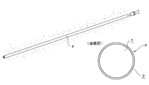
次に、本発明の第一実施形態について図1及び図2に基づいて説明する。なお図中、符号Fで指示するのものは、周面発光型の熱可塑性樹脂成形体であり、符号1で指示するものは、コア層である。また符号2で指示するものは、第一クラッド層である。"First embodiment"
Next, the first embodiment of the present invention will be described with reference to FIGS. 1 and 2. In the figure, what is designated by reference numeral F is a peripheral light emitting type thermoplastic resin molded body, and what is designated by
「熱可塑性樹脂成形体の構成及び使用方法」
[1]熱可塑性樹脂成形体の基本構成について
まず熱可塑性樹脂成形体の基本構成について説明する。本実施形態では、図1に示すように、熱可塑性エラストマーを主材料とするコア層1の周囲に、この熱可塑性エラストマーよりも屈折率の小さい熱可塑性樹脂を主材料とする第一クラッド層2を形成して軟質導光棒型の熱可塑性樹脂成形体Fを構成している。またコア層1と第一クラッド層2の各樹脂材料にはそれぞれ所定量の光拡散剤を添加すると共に、第一クラッド層2に対する光拡散剤の添加は、第一クラッド層2の全光線透過率が70%未満となるように行っている。"Construction and usage of thermoplastic resin molded product"
[1] Basic configuration of the thermoplastic resin molded product First, the basic configuration of the thermoplastic resin molded product will be described. In the present embodiment, as shown in FIG. 1, the
[2]熱可塑性樹脂成形体の使用方法について
また上記熱可塑性樹脂成形体Fについては、図1に示すように熱可塑性樹脂成形体Fの一端若しくは両端に光源を配置して端面に光を入射することにより、熱可塑性樹脂成形体Fの周面を発光させて使用する。なお本実施形態の熱可塑性樹脂成形体Fは、コア層1と第一クラッド層2に所定量の光拡散剤を添加しているため、光拡散剤が添加されていないものよりも発光ムラや発光色の黄変を抑えた状態で発光させることができる。[2] How to use the thermoplastic resin molded body For the above-mentioned thermoplastic resin molded body F, as shown in FIG. 1, a light source is arranged at one end or both ends of the thermoplastic resin molded body F, and light is incident on the end face. By doing so, the peripheral surface of the thermoplastic resin molded body F is made to emit light for use. In the thermoplastic resin molded product F of the present embodiment, since a predetermined amount of the light diffusing agent is added to the
[3]コア層について
次に上記熱可塑性樹脂成形体Fの各構成要素について説明する。まず上記コア層1の材料に関しては、本実施形態ではアクリル系熱可塑性エラストマーを使用している。具体的には、アクリル系熱可塑性エラストマーとして、アクリル酸エステル単位を主体とする重合体ブロック(a2)の両末端にそれぞれメタクリル酸エステル単位を主体とする重合体ブロック(a1)が結合した構造、すなわち、(a1)-(a2)-(a1)の構造(構造中の「-」は、化学結合を示す)を少なくとも有する、アクリル系ブロック共重合体の使用が好ましい。ここで、(a2)の両端の(a1)の分子量、組成などは同じであってもよいし、相互に異なっていてもよい。また(a1)-(a2)で表されるジブロック体を更に含んでいてもよい。[3] Core layer Next, each component of the thermoplastic resin molded body F will be described. First, regarding the material of the
なお上記メタクリル酸エステル単位となるメタクリル酸エステルとしては、例えば、メタクリル酸メチルなどを挙げることができ、これらのメタクリル酸エステルの1種から構成されていても、2種以上から構成されていてもよい。 Examples of the methacrylic acid ester as the methacrylic acid ester unit include methyl methacrylate, and the methacrylic acid ester may be composed of one kind or two or more kinds of these methacrylic acid esters. good.
また、上記アクリル酸エステル単位となるアクリル酸エステルとしては、例えば、アクリル酸メチル、アクリル酸n-ブチル、アクリル酸ベンジルなどを挙げることができ、これらのアクリル酸エステルの1種から構成されていても、2種以上から構成されていてもよく、アクリル酸n-ブチル、アクリル酸ベンジル、またはアクリル酸n-ブチル及びアクリル酸ベンジルから構成されていることが好ましい。アクリル酸n-ブチルとアクリル酸ベンジルの共重合体の場合には、その質量比(アクリル酸n-ブチル/アクリル酸ベンジル)は50/50~90/10の範囲にあることが好ましく、60/40~80/20の範囲にあることがより好ましい。 Examples of the acrylic acid ester as the acrylic acid ester unit include methyl acrylate, n-butyl acrylate, benzyl acrylate, and the like, and the acrylic acid ester is composed of one of these acrylic acid esters. Also, it may be composed of two or more kinds, and is preferably composed of n-butyl acrylate, benzyl acrylate, or n-butyl acrylate and benzyl acrylate. In the case of a copolymer of n-butyl acrylate and benzyl acrylate, the mass ratio (n-butyl acrylate / benzyl acrylate) is preferably in the range of 50/50 to 90/10, and is 60 /. More preferably, it is in the range of 40 to 80/20.
そして、コア層の材料としては、これらの中でも特に曲げ弾性率(ASTM D790)が50~500MPaである、メタクリル酸メチルとアクリル酸ブチルのブロック共重合体(以下、MMA-BAブロック共重合体と記載)の使用が好ましい。またコア層1の主材料に関しては、製造時における第一クラッド層2との共押出成形を考慮して、温度190℃・荷重5kgの試験条件下におけるMFRが2~10g/minの樹脂を使用することが好ましい。
As a material for the core layer, among these, a block copolymer of methyl methacrylate and butyl acrylate (hereinafter, MMA-BA block copolymer) having a flexural modulus (ASTM D790) of 50 to 500 MPa is used. The use of (described) is preferable. For the main material of the
[4]第一クラッド層について
上記第一クラッド層2の材料に関しては、屈折率がコア層1よりも小さいフッ素系樹脂の使用が好ましく、本実施形態ではETFE(エチレンとテトラフルオロエチレンの共重合体)やEFEP(ヘキサフルオロプロピレンとテトラフルオロエチレンとエチレンの共重合体)を使用している。但し、PVDF(ポリフッ化ビニリデン)等のフッ素系樹脂やその他の樹脂を使用することもできる。また第一クラッド層2の主材料には、コア層1との共押出成形を考慮して、融点が230℃以下の樹脂を使用するのが好ましい。[4] First clad layer As for the material of the first
なお上記第一クラッド層2にPVDFを使用する場合には、コア層1のアクリル系熱可塑性エラストマーに対する相溶性が高いため、使用時に第一クラッド層2とコア層1の剥離が生じ難くなるメリットがある。一方、上記フッ素系樹脂としてETFEを使用する場合には、ETFEの伸度(350~450%)の方がPVDFの伸度(200~300%)よりも大きく、またETFEの曲げ弾性率(800~1000MPa)の方がPVDFの曲げ弾性率(1400~1800MPa)よりも小さくなるため、熱可塑性樹脂成形体Fを曲げたときにクラッド層にシワが生じ難くなる。またETFEはPVDFに比べて可視光線透過率も高いため、発光輝度の減衰率を低く抑えることもできる。なお上記伸度の各数値はASTM D638による計測値であり、上記曲げ弾性率の各数値はASTM D790による計測値である。
When PVDF is used for the first
[5]光拡散剤について
上記コア層1及び第一クラッド層2に添加する光拡散剤に関しては、本実施形態では粉末状の酸化チタンを使用しているが、硫酸バリウムを使用することもできる。また光拡散剤の添加量に関しては、コア層1の樹脂材料に対し光拡散剤が重量比で0.5ppm~10ppmの割合となるように添加するのが好ましい。また第一クラッド層2の厚みを0.1~0.3mm(好ましくは0.2mm~0.3mm)とする場合には、第一クラッド層2の樹脂材料に対し光拡散剤が重量比で0.05~1.5%の割合となるように添加するのが好ましい。[5] About the light diffusing agent As for the light diffusing agent added to the
[6]ブルーイング剤について
また本実施形態では、上記コア層1に対しブルーイング剤(青色顔料や紫色顔料)を添加することによって熱可塑性樹脂成形体Fの発光色の黄変を抑制している。なおブルーイング剤の添加量については、コア層1の樹脂材料に対しブルーイング剤が重量比で0.1ppm~10ppmの割合となるように添加することが好ましい。[6] About the brewing agent In the present embodiment, the yellowing of the emission color of the thermoplastic resin molded body F is suppressed by adding the brewing agent (blue pigment or purple pigment) to the
[7]熱可塑性樹脂成形体の形状について
また本実施形態では、熱可塑性樹脂成形体Fを丸棒型の形状としているが、角形断面や複雑な断面形状の棒状に成形することもできる。また熱可塑性樹脂成形体Fの形状には、断面形状の縦横比が大きい板状のものも含まれる。[7] Shape of the thermoplastic resin molded body Further, in the present embodiment, the thermoplastic resin molded body F has a round bar shape, but it can also be molded into a bar shape having a square cross section or a complicated cross section shape. Further, the shape of the thermoplastic resin molded body F includes a plate shape having a large aspect ratio of the cross-sectional shape.
「熱可塑性樹脂成形体の製造方法」
次に上記熱可塑性樹脂成形体Fの製造方法について説明する。まず図2に示すように押出成形機の金型からコア層とクラッド層を同時に押出し、これらを一体化させた状態で冷却賦形を行った後、所定長さに切断して製造を行う。なお製造に際しては、コア層の主材に温度190℃・荷重5kgの試験条件下におけるMFRが2~10g/10minのアクリル系熱可塑性エラストマーを使用し、クラッド層の主材に融点が230℃以下のフッ素系樹脂を使用して、270℃以下の成形温度で共押出成形を行うのが好ましい。"Manufacturing method of thermoplastic resin molded product"
Next, a method for manufacturing the thermoplastic resin molded product F will be described. First, as shown in FIG. 2, the core layer and the clad layer are simultaneously extruded from the mold of the extruder, and the core layer and the clad layer are simultaneously extruded, cooled and shaped in a state where they are integrated, and then cut to a predetermined length for manufacturing. During manufacturing, an acrylic thermoplastic elastomer with an MFR of 2 to 10 g / 10 min under test conditions of a temperature of 190 ° C and a load of 5 kg was used as the main material of the core layer, and the melting point of the main material of the clad layer was 230 ° C or less. It is preferable to perform coextrusion molding at a molding temperature of 270 ° C. or lower using the fluororesin of the above.
『第二実施形態』
「熱可塑性樹脂成形体の構成」
[1]導光棒の基本構成について
次に本発明の第二実施形態について図3に基づいて以下に説明する。なお図中、符号3で指示するのものは、第二クラッド層である。本実施形態では、コア層1と第一クラッド層2の間に第二クラッド層3を形成して軟質導光棒型の熱可塑性樹脂成形体Fを構成している。そしてコア層1と外側の第一クラッド層2の各樹脂材料にそれぞれ光拡散剤を添加している。また第二クラッド層3の主材料には、第一クラッド層2と同じ樹脂材料を使用し、樹脂材料に光拡散剤を添加せずに使用している。このような構成を採用することで熱可塑性樹脂成形体Fの均一発光性を向上させることができる。"Second embodiment"
"Structure of thermoplastic resin molded product"
[1] Basic configuration of the light guide rod Next, a second embodiment of the present invention will be described below with reference to FIG. In the figure, what is indicated by
なお上記コア層1の主材料となる樹脂材料や、第一クラッド層2の主材料となる樹脂材料(第二クラッド層3と同じ樹脂材料)の条件に関しては、第一実施形態と同様である。また光拡散剤の材料や、コア層1の樹脂材料に対する光拡散剤の添加量、製造方法等の条件も第一実施形態と同様である。
The conditions of the resin material that is the main material of the
[2]クラッド層の厚みと光拡散剤の添加量について
一方、クラッド層の厚みに関しては、第一クラッド層2に対する第二クラッド層3の厚みの比率を50%~150%とし、第一クラッド層2と第二クラッド層3の合計厚みが0.15mm~0.4mmとなるようにするのが好ましい。そして、この厚みで形成される第一クラッド層2の樹脂材料に対し光拡散剤を重量比で0.05~1.5%の割合となるように添加するのが好ましい。なお本実施形態においても、第一クラッド層2に対する光拡散剤の添加は、第一クラッド層2と第二クラッド層3の二層の全光線透過率が70%未満となるように行うのが好ましい。[2] Thickness of clad layer and amount of light diffusing agent added On the other hand, regarding the thickness of the clad layer, the ratio of the thickness of the second
[効果の実証試験(i)]
次に本発明の効果の実証試験(i)について説明する。まず本試験では、製造条件(コア層への光拡散剤及びブルーイング剤の添加、光拡散剤の添加量、クラッド層の構成)の異なる複数のサンプル(下記比較例1~3並びに実施例1~5)を作製し、これらの各サンプルについて、発光性能(発光輝度及び減衰率)、発光色の色度変化の評価を行った。なお本試験では、光拡散剤として粉末状の酸化チタンを使用した。以下に比較例1~3並びに実施例1~5の各サンプルの製造条件について記載する。[Effect verification test (i)]
Next, the verification test (i) of the effect of the present invention will be described. First, in this test, a plurality of samples having different production conditions (addition of light diffusing agent and brewing agent to the core layer, amount of light diffusing agent added, composition of clad layer) (the following Comparative Examples 1 to 3 and Example 1) To 5) were prepared, and the emission performance (luminance and attenuation rate) and the change in chromaticity of the emission color were evaluated for each of these samples. In this test, powdered titanium oxide was used as the light diffusing agent. The production conditions of each sample of Comparative Examples 1 to 3 and Examples 1 to 5 are described below.
「比較例1」
この比較例1では、丸棒状の熱可塑性樹脂成形体を、コア層と厚み0.24mmの第一クラッド層から構成した。またコア層の主材料には、温度190℃・荷重2.16kgの試験条件下におけるMFRが3.1g/10min、曲げ弾性率が400MPaのMMA-BAブロック共重合体を使用し、第一クラッド層の主材料には、融点192℃、伸度417%、曲げ弾性率959MPa、温度297℃・荷重5kgの試験条件下におけるMFRが78.6g/10minのETFEを使用して、熱可塑性樹脂成形体を共押出成形により作製した。またコア層には光拡散剤を添加せず、第一クラッド層にのみ光拡散剤を、第一クラッド層の樹脂材料に対し光拡散剤が重量比で0.065%の割合となるように添加した。なお第一クラッド層の全光線透過率は65.2%であった。"Comparative Example 1"
In Comparative Example 1, a round bar-shaped thermoplastic resin molded body was composed of a core layer and a first clad layer having a thickness of 0.24 mm. The main material of the core layer is an MMA-BA block copolymer with an MFR of 3.1 g / 10 min and a flexural modulus of 400 MPa under test conditions at a temperature of 190 ° C and a load of 2.16 kg. The main material is ETFE with a melting point of 192 ° C, elongation of 417%, flexural modulus of 959MPa, temperature of 297 ° C and load of 5kg, and MFR of 78.6g / 10min. It was manufactured by extrusion molding. No light diffusing agent was added to the core layer, and the light diffusing agent was added only to the first clad layer so that the light diffusing agent had a weight ratio of 0.065% with respect to the resin material of the first clad layer. .. The total light transmittance of the first clad layer was 65.2%.
「比較例2」
この比較例2では、丸棒状の熱可塑性樹脂成形体を、コア層と厚み0.1mmの第二クラッド層及び厚み0.11mmの第一クラッド層から構成した。またコア層の主材料には、比較例1と同じMMA-BAブロック共重合体を使用し、また第二クラッド層と第一クラッド層の主材料には、比較例1の第一クラッド層と同じETFEを使用して、熱可塑性樹脂成形体を共押出成形により作製した。またコア層には光拡散剤を添加せず、第一クラッド層にのみ光拡散剤を、第一クラッド層2の樹脂材料に対し光拡散剤が重量比で1.3%の割合となるように添加した。なお第一クラッド層と第二クラッド層の二層の全光線透過率は24.5%であった。"Comparative Example 2"
In Comparative Example 2, the round bar-shaped thermoplastic resin molded body was composed of a core layer, a second clad layer having a thickness of 0.1 mm, and a first clad layer having a thickness of 0.11 mm. The same MMA-BA block copolymer as in Comparative Example 1 is used as the main material of the core layer, and the first clad layer of Comparative Example 1 is used as the main material of the second clad layer and the first clad layer. Using the same ETFE, a thermoplastic resin molded product was produced by coextrusion molding. No light diffusing agent was added to the core layer, and the light diffusing agent was added only to the first clad layer so that the light diffusing agent had a weight ratio of 1.3% with respect to the resin material of the first
「比較例3」
この比較例3では、ブルーイング剤である青色顔料及び紫色顔料を、コア層の樹脂材料に対し各顔料が重量比で1ppmの割合となるようにそれぞれ添加し、また酸化防止剤を、コア層の樹脂材料に対し酸化防止剤が重量比で0.1%の割合となるように添加した。なお第一クラッド層と第二クラッド層の二層の全光線透過率は24.5%であり、その他の条件は比較例2と同様である。"Comparative Example 3"
In Comparative Example 3, a blue pigment and a purple pigment, which are brewing agents, are added to the resin material of the core layer so that each pigment has a weight ratio of 1 ppm, and an antioxidant is added to the core layer. The antioxidant was added so as to have a ratio of 0.1% by weight to the resin material of. The total light transmittance of the two layers of the first clad layer and the second clad layer is 24.5%, and other conditions are the same as in Comparative Example 2.
「実施例1」
この実施例1では、丸棒状の熱可塑性樹脂成形体を、コア層と厚み0.24mmの第一クラッド層から構成した。またコア層の主材料には、温度190℃・荷重2.16kgの試験条件下におけるMFRが3.1g/10min、曲げ弾性率が400MPaのMMA-BAブロック共重合体を使用し、第一クラッド層の主材料には、融点192℃、伸度417%、曲げ弾性率959MPa、温度297℃・荷重5kgの試験条件下におけるMFRが78.6g/10minのETFEを使用して、熱可塑性樹脂成形体を共押出成形により作製した。"Example 1"
In this Example 1, a round bar-shaped thermoplastic resin molded body was composed of a core layer and a first clad layer having a thickness of 0.24 mm. The main material of the core layer is an MMA-BA block copolymer with an MFR of 3.1 g / 10 min and a flexural modulus of 400 MPa under test conditions at a temperature of 190 ° C and a load of 2.16 kg. The main material is ETFE with a melting point of 192 ° C, elongation of 417%, flexural modulus of 959MPa, temperature of 297 ° C and load of 5kg, and MFR of 78.6g / 10min. It was manufactured by extrusion molding.
またコア層には、光拡散剤をコア層の樹脂材料に対し光拡散剤が重量比で1ppmの割合となるように添加した。一方、第一クラッド層には、光拡散剤を、第一クラッド層の樹脂材料に対し光拡散剤が重量比で0.065%の割合となるように添加した。またコア層にはブルーイング剤である青色顔料及び紫色顔料を、コア層の樹脂材料に対し各顔料が重量比で1ppmの割合となるようにそれぞれ添加し、また酸化防止剤を、コア層の樹脂材料に対し酸化防止剤が重量比で0.1%の割合となるように添加した。なお第一クラッド層の全光線透過率は65.2%であった。 Further, a light diffusing agent was added to the core layer so that the light diffusing agent had a weight ratio of 1 ppm with respect to the resin material of the core layer. On the other hand, a light diffusing agent was added to the first clad layer so that the ratio of the light diffusing agent to the resin material of the first clad layer was 0.065% by weight. In addition, blue pigments and purple pigments, which are brewing agents, are added to the core layer so that each pigment has a weight ratio of 1 ppm to the resin material of the core layer, and an antioxidant is added to the core layer. Antioxidants were added to the resin material at a ratio of 0.1% by weight. The total light transmittance of the first clad layer was 65.2%.
「実施例2」
この実施例2では、丸棒状の熱可塑性樹脂成形体を、コア層と厚み0.1mmの第二クラッド層及び厚み0.12mmの第一クラッド層を形成して構成した。またコア層の主材料には、実施例1と同じMMA-BAブロック共重合体を使用し、また第二クラッド層と第一クラッド層の主材料には、実施例1の第一クラッド層と同じETFEを使用して、熱可塑性樹脂成形体を共押出成形により作製した。またコア層には、光拡散剤をコア層の樹脂材料に対し光拡散剤が重量比で0.5ppmの割合となるように添加した。"Example 2"
In Example 2, a round bar-shaped thermoplastic resin molded body was formed by forming a core layer, a second clad layer having a thickness of 0.1 mm, and a first clad layer having a thickness of 0.12 mm. The same MMA-BA block copolymer as in Example 1 is used as the main material of the core layer, and the first clad layer of Example 1 is used as the main material of the second clad layer and the first clad layer. Using the same ETFE, a thermoplastic resin molded product was produced by coextrusion molding. Further, a light diffusing agent was added to the core layer so that the light diffusing agent had a weight ratio of 0.5 ppm with respect to the resin material of the core layer.
一方、第二クラッド層には光拡散剤を添加せず、第一クラッド層にのみ光拡散剤を、第一クラッド層の樹脂材料に対し光拡散剤が重量比で1.3%の割合となるように添加した。またコア層にはブルーイング剤である青色顔料及び紫色顔料を、コア層の樹脂材料に対し各顔料が重量比で1ppmの割合となるようにそれぞれ添加し、また酸化防止剤を、コア層の樹脂材料に対し酸化防止剤が重量比で0.1%の割合となるように添加した。なお第一クラッド層と第二クラッド層の二層の全光線透過率は18.2%であった。 On the other hand, no light diffusing agent is added to the second clad layer, the light diffusing agent is applied only to the first clad layer, and the light diffusing agent is 1.3% by weight of the resin material of the first clad layer. Was added to. In addition, blue pigments and purple pigments, which are brewing agents, are added to the core layer so that each pigment has a weight ratio of 1 ppm to the resin material of the core layer, and an antioxidant is added to the core layer. Antioxidants were added to the resin material at a ratio of 0.1% by weight. The total light transmittance of the two layers, the first clad layer and the second clad layer, was 18.2%.
「実施例3」
この実施例3においては、コア層に光拡散剤を、コア層の樹脂材料に対し光拡散剤が重量比で0.8ppmの割合となるように添加した。なおその他の条件は実施例2と同様である。
「実施例4」
この実施例4においては、コア層に光拡散剤を、コア層の樹脂材料に対し光拡散剤が重量比で1ppmの割合となるように添加した。なおその他の条件は実施例2と同様である。
「実施例5」
この実施例5においては、コア層に光拡散剤を、コア層の樹脂材料に対し光拡散剤が重量比で3ppmの割合となるように添加した。なおその他の条件は実施例2と同様である。"Example 3"
In Example 3, a light diffusing agent was added to the core layer so that the light diffusing agent had a weight ratio of 0.8 ppm with respect to the resin material of the core layer. Other conditions are the same as in Example 2.
"Example 4"
In Example 4, a light diffusing agent was added to the core layer so that the light diffusing agent had a weight ratio of 1 ppm with respect to the resin material of the core layer. Other conditions are the same as in Example 2.
"Example 5"
In Example 5, a light diffusing agent was added to the core layer so that the light diffusing agent had a weight ratio of 3 ppm with respect to the resin material of the core layer. Other conditions are the same as in Example 2.
以下に比較例1~3及び実施例1~5の各サンプルの製造条件をまとめた表を示す。

<発光性能の評価>
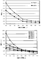
次に上記比較例1~3並びに実施例1~5のサンプルについて、寸法を長さ1000mm、直径6.3mmとして、光源からの距離が100~900mmの部位の発光輝度を100mm間隔で測定した。なお本試験では、発光輝度の測定を、サンプルの被測定部位から垂直方向に600mm離れた位置に分光放射輝度計(CS-2000コニカミノルタ製)を配置して行った。また光源には、駆動電流20mA、輝度25cd/m2、指向特性30°のものを使用した。測定条件をまとめた表を以下に示す。

Next, with respect to the samples of Comparative Examples 1 to 3 and Examples 1 to 5, the emission luminance of a portion having a length of 1000 mm and a diameter of 6.3 mm and a distance of 100 to 900 mm from the light source was measured at 100 mm intervals. In this test, the emission brightness was measured by placing a spectral radiance meter (manufactured by CS-2000 Konica Minolta) at a
そして、上記測定結果をグラフ化した図4を見ても分かるように、クラッド層が一層から成る形態において、実施例1の熱可塑性樹脂成形体の方が比較例1の熱可塑性樹脂成形体よりも発光輝度が全体的に大きくなっていることが確認できた。またクラッド層が二層から成る形態においても、実施例2~5の熱可塑性樹脂成形体の方が比較例2及び3の熱可塑性樹脂成形体よりも全体の発光輝度が大きくなっていることも確認できた。下記表に発光輝度と減衰率の詳細なデータを示す(輝度の単位はcd/m2)。

<発光色の色度変化の評価>
次に上記比較例1~3並びに実施例1~5のサンプルについて、光源から近い側から遠い側にかけての発光色の色度変化を調べたところ、図5に示すようにクラッド層が一層から成る形態において、実施例1の熱可塑性樹脂成形体の方が比較例1の熱可塑性樹脂成形体よりも発光色の黄変が抑制されていることが確認できた。またクラッド層が二層から成る形態においても、実施例2~5の熱可塑性樹脂成形体の方が比較例2及び3の熱可塑性樹脂成形体よりも発光色の黄変が抑制されていることが確認できた。<Evaluation of chromaticity change of emission color>
Next, with respect to the samples of Comparative Examples 1 to 3 and Examples 1 to 5, the change in chromaticity of the emitted color from the side closer to the light source to the side farther from the light source was investigated, and as shown in FIG. 5, the clad layer was composed of one layer. In the embodiment, it was confirmed that the thermoplastic resin molded product of Example 1 suppressed the yellowing of the emission color as compared with the thermoplastic resin molded product of Comparative Example 1. Further, even in the form in which the clad layer is composed of two layers, the thermoplastic resin molded products of Examples 2 to 5 have more suppressed yellowing of the emission color than the thermoplastic resin molded products of Comparative Examples 2 and 3. Was confirmed.
なお上記発光色の色度変化の評価は、CIE色度図を用いて光源からの距離が100~900mmの部位の発光色を100mm間隔で測定し、最小のx値・y値(青色寄りの座標)から最大のx値・y値(黄色寄りの座標)への変化の大きさを比較して行った。色度変化量の詳細なデータを下記に示す。下記表からも分かるように実施例5以外は光源に近い部位のx値・y値が最小で、光源から遠い部位のx値・y値が最大となっている。

[効果の実証試験(ii)]
次に本発明の効果の実証試験(ii)について説明する。本試験では、コア層とクラッド層に使用する材料、及び製法が異なる複数のサンプル(下記比較例4・5並びに実施例6)を作製し、これらの各サンプルについて、落球試験を行って試験後における各サンプルの発光性能(発光輝度)の評価を行った。なお本試験では、光拡散剤として粉末状の酸化チタンを使用した。以下に比較例4・5並びに実施例6の各サンプルの製造条件について説明する。[Effect verification test (ii)]
Next, a verification test (ii) of the effect of the present invention will be described. In this test, a plurality of samples (Comparative Examples 4 and 5 and Example 6 below) having different materials and manufacturing methods for the core layer and the clad layer were prepared, and each of these samples was subjected to a ball drop test after the test. The emission performance (emission brightness) of each sample was evaluated. In this test, powdered titanium oxide was used as the light diffusing agent. The production conditions of each sample of Comparative Examples 4 and 5 and Example 6 will be described below.
「比較例4」
この比較例4では、周面発光型の熱可塑性樹脂成形体を、コア層と第一クラッド層から成る外径3.5mmの丸棒状に構成した。またコア層の材料には、ポリマーポリオールとしてポリオキシプロピレントリオールとポリオキシプロピレンジオールを使用し、ヒドロキシ基反応性多官能化合物としてヘキサメチレンジイソシアネートを使用した。また第一クラッド層の材料には、テトラフルオロエチレン・ヘキサフルオロプロピレン共重合体(FEP)を使用した。そして第一クラッド層を構成するチューブ内に、コア層の材料を混合した状態で充填して加熱硬化させることにより、周面発光型の熱可塑性樹脂成形体を作製した。"Comparative Example 4"
In Comparative Example 4, the peripheral light emitting type thermoplastic resin molded body was formed into a round bar having an outer diameter of 3.5 mm composed of a core layer and a first clad layer. Further, as the material of the core layer, polyoxypropylene triol and polyoxypropylene diol were used as the polymer polyol, and hexamethylene diisocyanate was used as the hydroxy group-reactive polyfunctional compound. A tetrafluoroethylene / hexafluoropropylene copolymer (FEP) was used as the material for the first clad layer. Then, the tube constituting the first clad layer was filled with the material of the core layer in a mixed state and heat-cured to produce a peripheral light emitting type thermoplastic resin molded body.
「比較例5」
この比較例5では、周面発光型の熱可塑性樹脂成形体を、コア層と第一クラッド層から成る外径3.0mmの丸棒状に構成した。またコア層の材料には、重合性モノマー(重量比で100:1の、n-ブチルメタクリレートとトリエチレングリコールジメタクリレートとの混合液)に、重合開始剤としてビス(4-t-ブチルシクロヘキシル)パーオキシジカーボネートを加えたものを使用した。また第一クラッド層の材料には、テトラフルオロエチレン-ヘキサフルオロプロピレン共重合体を使用した。そして押出し機でチューブ状に成形した第一クラッド層内に、コア形成材料を加圧充填して重合させることにより、周面発光型の熱可塑性樹脂成形体を作製した。"Comparative Example 5"
In Comparative Example 5, the peripheral light emitting type thermoplastic resin molded body was formed into a round bar having an outer diameter of 3.0 mm composed of a core layer and a first clad layer. The core layer is made of a polymerizable monomer (100: 1 by weight, a mixture of n-butyl methacrylate and triethylene glycol dimethacrylate) and bis (4-t-butylcyclohexyl) as a polymerization initiator. The one to which peroxydicarbonate was added was used. A tetrafluoroethylene-hexafluoropropylene copolymer was used as the material for the first clad layer. Then, a core-forming material was pressure-filled and polymerized in the first clad layer formed into a tube shape by an extruder to produce a peripheral light emitting type thermoplastic resin molded body.
「実施例6」
この実施例6では、周面発光型の熱可塑性樹脂成形体を、コア層と第一クラッド層から成る外径3.5mmの丸棒状に構成した。またコア層の主材料には、温度190℃・荷重2.16kgの試験条件下におけるMFRが3.1g/10min、曲げ弾性率が400MPaのMMA-BAブロック共重合体を使用し、第一クラッド層の主材料には、融点192℃、伸度417%、曲げ弾性率959MPa、温度297℃・荷重5kgの試験条件下におけるMFRが78.6g/10minのETFEを使用して、熱可塑性樹脂成形体を共押出成形により作製した。"Example 6"
In Example 6, the peripheral light emitting type thermoplastic resin molded body was formed into a round bar having an outer diameter of 3.5 mm composed of a core layer and a first clad layer. The main material of the core layer is an MMA-BA block copolymer with an MFR of 3.1 g / 10 min and a flexural modulus of 400 MPa under test conditions at a temperature of 190 ° C and a load of 2.16 kg. The main material is ETFE with a melting point of 192 ° C, elongation of 417%, flexural modulus of 959MPa, temperature of 297 ° C and load of 5kg, and MFR of 78.6g / 10min. It was manufactured by extrusion molding.
<落球試験について>
次に上記落球試験の方法について説明する。本試験では、200mmに切断した各サンプルを、任意の温度(常温・-30℃・80℃)に約3時間放置した後、このサンプルの中央部に、質量約1040gの鋼球(サイズ2 1/2インチ)を306mmの高さから落下させて衝撃を与えた。なお試験は、厚さ約30mmの鉄板上に試料を設置して行った。<About the falling ball test>
Next, the method of the above-mentioned falling ball test will be described. In this test, each sample cut to 200 mm was left at an arbitrary temperature (normal temperature, -30 ° C, 80 ° C) for about 3 hours, and then a steel ball (
<発光性能の評価>
次に発光性能の評価方法について説明する。上記落球試験を行った各サンプルにおける落下点前、落下点、落下点後の部位の発光輝度を測定した。なお本試験では、発光輝度の測定を、サンプルの被測定部位から垂直方向に600mm離れた位置に分光放射輝度計(CS-2000コニカミノルタ製)を配置して行った。また光源には、駆動電流20mA、輝度25cd/m2、指向特性30°のものを使用した。<Evaluation of light emission performance>
Next, an evaluation method of light emission performance will be described. In each sample subjected to the above-mentioned falling ball test, the emission brightness of the part before the falling point, the falling point, and the part after the falling point was measured. In this test, the emission brightness was measured by placing a spectral radiance meter (manufactured by CS-2000 Konica Minolta) at a
そして、各サンプルの発光輝度を測定した結果、図6及び図7に示されるように、-30℃条件下の落球試験後のサンプルにおいて、実施例6のサンプルの方が比較例4のサンプルよりも、落下点後の部位における発光輝度が明らかに大きいことが確認できた。なお外観面においても、-30℃条件下の落球試験後において、実施例6のサンプルは落下点にへこみが生じただけだったのに対し、比較例4のサンプルは落下点に内部損傷による白化が見られた。 Then, as a result of measuring the emission luminance of each sample, as shown in FIGS. 6 and 7, in the sample after the falling ball test under the condition of -30 ° C, the sample of Example 6 was better than the sample of Comparative Example 4. However, it was confirmed that the emission brightness at the site after the drop point was clearly large. In terms of appearance, after the ball drop test under the condition of -30 ° C, the sample of Example 6 had only a dent at the drop point, whereas the sample of Comparative Example 4 had whitening due to internal damage at the drop point. It was observed.
一方、80℃条件下の落球試験後のサンプルにおいては、実施例6のサンプルの方が比較例5のサンプルよりも、落下点後の部位における発光輝度が明らかに大きいことが確認できた。なお外観面においても、80℃条件下の落球試験後において、実施例6のサンプルは落下点にへこみが生じただけだったのに対し、比較例5のサンプルは落下点に内部損傷による白化が見られた。 On the other hand, in the sample after the falling ball test under the condition of 80 ° C., it was confirmed that the sample of Example 6 had a clearly higher emission brightness at the site after the falling point than the sample of Comparative Example 5. In terms of appearance, after the ball drop test under 80 ° C. conditions, the sample of Example 6 had only a dent at the drop point, whereas the sample of Comparative Example 5 had whitening due to internal damage at the drop point. It was seen.
以上の実証試験(ii)の結果により、コア層の主材料にアクリル系熱可塑性エラストマーを使用し、第一クラッド層の主材料にフッ素系樹脂を使用して共押出成形により製造した実施例6のサンプルの方が、その他の材料・製法を採用した比較例4・5のサンプルよりも衝撃による外観悪化や発光性能の低下が起き難いことが確認できた。 Based on the results of the above verification test (ii), Example 6 was manufactured by coextrusion molding using an acrylic thermoplastic elastomer as the main material of the core layer and a fluororesin as the main material of the first clad layer. It was confirmed that the sample of No. 1 is less likely to cause deterioration in appearance and light emission performance due to impact than the samples of Comparative Examples 4 and 5 using other materials and manufacturing methods.
本発明の熱可塑性樹脂成形体は、光装飾の方法や固定される対象物に合わせて柔軟に屈曲させて使用できるだけでなく、発光輝度も全体的に向上させることができ、しかも、光源から遠い部位での発光色の黄変も抑制できることから、発光性能及び耐衝撃性に優れた周面発光型の熱可塑性樹脂成形体、特に導光棒として好適に使用できる。 The thermoplastic resin molded body of the present invention can be flexibly bent and used according to the method of light decoration and the object to be fixed, and can also improve the emission brightness as a whole, and is far from the light source. Since it is possible to suppress yellowing of the emission color at the site, it can be suitably used as a peripheral surface emitting type thermoplastic resin molded body having excellent emission performance and impact resistance, particularly as a light guide rod.
かかる導光棒としては、自動車内装用照明装置、具体的には、車両のインストルメントパネル周り、カーオディオ・カーナビ周り、ドアパネル、コンソールボックス、ピラーに設置する補助照明として使用できる。その他、カーテシーランプ、マップランプ、ルームランプ、フロアランプ、フットランプ、天井ランプ、ドアランプに適用することもできる。 The light guide rod can be used as a lighting device for an automobile interior, specifically, an auxiliary lighting installed around an instrument panel of a vehicle, around a car audio / car navigation system, a door panel, a console box, and a pillar. In addition, it can be applied to courtesy lamps, map lamps, room lamps, floor lamps, foot lamps, ceiling lamps, and door lamps.
また、自動車外装用照明装置、例えば自動車用ヘッドランプやテールランプ、ブレーキランプ、サイドマーカーランプ、ナンバープレートランプなどにも適用することもできる。また、太陽光の伝送、車載用配線・移動体配線・FA機器配線等の光信号伝送、液面レベルセンサー、感圧センサー等の光学センサー、内視鏡等のイメージガイド、光学機器のライトガイトにも適用することもできる。 It can also be applied to automobile exterior lighting devices such as automobile headlamps, tail lamps, brake lamps, side marker lamps, license plate lamps and the like. In addition, solar transmission, optical signal transmission such as in-vehicle wiring, mobile wiring, FA equipment wiring, optical sensors such as liquid level sensors and pressure sensitive sensors, image guides such as endoscopes, and light guides for optical equipment. It can also be applied to.
その他、携帯電話、デジカメ、腕時計、パチンコ台、スロット台、自動販売機、犬の首輪、装飾具、交通標識、洗面台、シャワー、浴槽の湯温表示機、OA機器、家庭用電気製品、光学機器、各種建材、階段、手すり、電車のホーム、屋外看板、バリアフリー空間等のイルミネーションや照明、液晶表示部のバックライト、可変表示体、美術館や博物館向けの熱線や紫外線カット照明におけるライトガイド等としても好適に使用することができる。また、この光伝送体に光源を組み合わせて、照明装置として各種のイルミネーションや照明設備にも使用することができる。 In addition, mobile phones, digital cameras, watches, pachinko stands, slot stands, vending machines, dog collars, decorations, traffic signs, washstands, showers, bath water temperature indicators, OA equipment, household electrical appliances, optics. Illuminations and lighting for equipment, various building materials, stairs, handrails, train platforms, outdoor signs, barrier-free spaces, etc., backlights for LCD displays, variable displays, light guides for heat rays and UV-cut lighting for museums, etc. Can also be suitably used. Further, by combining this optical transmitter with a light source, it can be used as a lighting device for various illuminations and lighting equipment.
1 コア層
2 第一クラッド層
3 第二クラッド層
F 熱可塑性樹脂成形体1
Claims (5)
コア層(1)の樹脂材料に対して添加されている光拡散剤の割合は重量比で0.5ppm~10ppmであり、
前記コア層(1)と前記第一クラッド層(2)の間には、前記第一クラッド層(2)と同じ樹脂材料を主材料とし、かつ、樹脂材料に光拡散剤が添加されていない第二クラッド層(3)が形成されており、
前記第一クラッド層(2)に対する前記第二クラッド層(3)の厚みの比率が50%~150%であり、かつ、前記第一クラッド層(2)と前記第二クラッド層(3)の合計厚みが0.15mm~0.4mmであることを特徴とする周面発光型の熱可塑性樹脂成形体。 It has at least a core layer (1) whose main material is a thermoplastic elastomer and a first clad layer (2) whose main material is a thermoplastic resin having a refractive index smaller than that of the thermoplastic elastomer of the core layer (1). Moreover, a light diffusing agent is added to each of the resin materials of the core layer (1) and the first clad layer (2), and the total light transmittance of the first clad layer (2) is less than 70%. The ratio of the light diffusing agent added to the resin material of the first clad layer (2) is 0.05 to 1.5% by weight, while the ratio is 0.05 to 1.5%.
The ratio of the light diffusing agent added to the resin material of the core layer (1) is 0.5 ppm to 10 ppm by weight.
The same resin material as the first clad layer (2) is used as the main material between the core layer (1) and the first clad layer (2), and no light diffusing agent is added to the resin material. The second clad layer (3) is formed,
The ratio of the thickness of the second clad layer (3) to the first clad layer (2) is 50% to 150%, and the ratio of the first clad layer (2) to the second clad layer (3). A peripheral light emitting type thermoplastic resin molded body having a total thickness of 0.15 mm to 0.4 mm.
Applications Claiming Priority (3)
| Application Number | Priority Date | Filing Date | Title |
|---|---|---|---|
| JPPCT/JP2017/013681 | 2017-03-31 | ||
| JP2017013681 | 2017-03-31 | ||
| PCT/JP2018/010622 WO2018180644A1 (en) | 2017-03-31 | 2018-03-16 | Thermoplastic resin molding of peripheral surface light-emitting type |
Publications (3)
| Publication Number | Publication Date |
|---|---|
| JPWO2018180644A1 JPWO2018180644A1 (en) | 2020-02-06 |
| JPWO2018180644A5 JPWO2018180644A5 (en) | 2022-01-28 |
| JP7083336B2 true JP7083336B2 (en) | 2022-06-10 |
Family
ID=63675549
Family Applications (1)
| Application Number | Title | Priority Date | Filing Date |
|---|---|---|---|
| JP2019509312A Active JP7083336B2 (en) | 2017-03-31 | 2018-03-16 | Peripheral light emitting type thermoplastic resin molded body |
Country Status (8)
| Country | Link |
|---|---|
| US (1) | US11086062B2 (en) |
| EP (1) | EP3605170B1 (en) |
| JP (1) | JP7083336B2 (en) |
| KR (1) | KR20190129037A (en) |
| CN (1) | CN110383125A (en) |
| CA (1) | CA3058090C (en) |
| ES (1) | ES2937909T3 (en) |
| WO (1) | WO2018180644A1 (en) |
Families Citing this family (5)
| Publication number | Priority date | Publication date | Assignee | Title |
|---|---|---|---|---|
| JP7175823B2 (en) * | 2019-03-28 | 2022-11-21 | フクビ化学工業株式会社 | Peripheral light-emitting type light guide bar |
| JP2020112616A (en) * | 2019-01-09 | 2020-07-27 | フクビ化学工業株式会社 | Light guide rod of peripheral surface light-emitting type |
| WO2020145107A1 (en) * | 2019-01-09 | 2020-07-16 | フクビ化学工業株式会社 | Peripheral surface light emitting-type light guide bar |
| JP2020112617A (en) * | 2019-01-09 | 2020-07-27 | フクビ化学工業株式会社 | Light guide rod of peripheral surface light-emitting type |
| JP7468302B2 (en) | 2020-11-05 | 2024-04-16 | 東レ株式会社 | Illuminated plastic optical fiber and illuminated plastic optical fiber cord |
Citations (7)
| Publication number | Priority date | Publication date | Assignee | Title |
|---|---|---|---|---|
| WO2010001589A1 (en) | 2008-07-02 | 2010-01-07 | パナソニック株式会社 | Guiding device |
| JP2012103617A (en) | 2010-11-12 | 2012-05-31 | Sekisui Chem Co Ltd | Light diffusing rod and manufacturing method thereof |
| JP2013057924A (en) | 2011-08-18 | 2013-03-28 | Fukuvi Chem Ind Co Ltd | Optical fiber type linear luminous body |
| JP2013058334A (en) | 2011-09-07 | 2013-03-28 | Mitsubishi Rayon Co Ltd | Light guide body for plane light source device, method for manufacturing the same, and plane light source device |
| JP2015507763A (en) | 2011-12-19 | 2015-03-12 | コーニング インコーポレイテッド | High efficiency uniform UV light diffusing fiber |
| WO2016064940A1 (en) | 2014-10-23 | 2016-04-28 | Corning Incorporated | Light-diffusing optical fiber having nanostructured inner and outer core regions |
| WO2016190138A1 (en) | 2015-05-22 | 2016-12-01 | 株式会社クラレ | Acrylic block copolymer, resin composition and molded body comprising same, and optical member |
Family Cites Families (24)
| Publication number | Priority date | Publication date | Assignee | Title |
|---|---|---|---|---|
| JPH09325221A (en) * | 1996-04-04 | 1997-12-16 | Hitachi Cable Ltd | Lighting device |
| US6366727B1 (en) * | 1996-11-07 | 2002-04-02 | 3M Innovative Properties Company | Light-illuminating rods |
| US6123442A (en) * | 1997-10-24 | 2000-09-26 | Minnesota Mining And Manufacturing Company | Articles with diffuse reflection of light from light fibers |
| US6091878A (en) * | 1997-11-20 | 2000-07-18 | Rohm And Haas Company | Flexible light pipe for side-lit applications |
| JPH11326644A (en) * | 1998-05-20 | 1999-11-26 | Bridgestone Corp | Light transmission tube and its production |
| US6519401B1 (en) * | 1998-10-28 | 2003-02-11 | 3M Innovative Properties Company | Light fibers and methods for producing the same |
| JP4740431B2 (en) | 1998-10-28 | 2011-08-03 | スリーエム カンパニー | Optical fiber and manufacturing method thereof |
| US6236460B1 (en) * | 1999-01-29 | 2001-05-22 | E. I. Du Pont De Nemours And Company | Method to determine light scattering efficiency of pigments |
| JP3998502B2 (en) * | 2002-04-05 | 2007-10-31 | スリーエム イノベイティブ プロパティズ カンパニー | Gaze guidance lighting device |
| JP2004342411A (en) * | 2003-05-14 | 2004-12-02 | Sharp Corp | Illuminating device and illuminating system including the same |
| WO2006046749A1 (en) * | 2004-10-28 | 2006-05-04 | Fujifilm Corporation | Plastic optical member and producing method thereof |
| JP2006317844A (en) * | 2005-05-16 | 2006-11-24 | Three M Innovative Properties Co | Side emission optical fiber and light emitting apparatus |
| FR2891455A1 (en) * | 2005-09-30 | 2007-04-06 | Fabre Pierre Dermo Cosmetique | Oblong particles in the form of a pile made up of a organogellifying fibers in xerogel form, useful e.g. in dermo-cosmetic composition e.g. to hide wrinkles, ridules and cutaneous imperfections |
| KR101288726B1 (en) * | 2005-11-10 | 2013-07-23 | 테이진 카세이 가부시키가이샤 | Optical device and achromatic lens |
| JP2009059583A (en) * | 2007-08-31 | 2009-03-19 | Mitsubishi Rayon Co Ltd | Side-face light leakage illuminating device |
| JP5341391B2 (en) * | 2008-05-16 | 2013-11-13 | スリーエム イノベイティブ プロパティズ カンパニー | Side-emitting optical fiber |
| JP5476027B2 (en) * | 2009-04-16 | 2014-04-23 | ダイセルポリマー株式会社 | AS resin composition |
| US8634687B2 (en) * | 2009-10-19 | 2014-01-21 | Sumitomo Electric Industries, Ltd. | Coated plastic cladding optical fiber and optical fiber cable |
| US8331750B2 (en) * | 2010-02-01 | 2012-12-11 | Enlighting Inc | Optical fibers having a surface light field emulation (s-LiFE) segment and method of making the same |
| JP2012103618A (en) * | 2010-11-12 | 2012-05-31 | Sekisui Chem Co Ltd | Light diffusing rod |
| CN102673024A (en) * | 2011-03-11 | 2012-09-19 | 北京君鹏鑫新技术开发有限公司 | Linear luminous body and manufacturing method thereof |
| JP6089703B2 (en) * | 2011-09-14 | 2017-03-08 | 三菱レイヨン株式会社 | Plastic optical fiber cable |
| JP5888788B2 (en) * | 2013-09-27 | 2016-03-22 | フクビ化学工業株式会社 | Linear illuminant and method for producing the same |
| US10197722B2 (en) * | 2015-09-02 | 2019-02-05 | Fukuvi Chemical Industry Co., Ltd. | Flexible linear light emitting element and a method of producing the same |
-
2018
- 2018-03-16 CA CA3058090A patent/CA3058090C/en active Active
- 2018-03-16 ES ES18776795T patent/ES2937909T3/en active Active
- 2018-03-16 EP EP18776795.9A patent/EP3605170B1/en active Active
- 2018-03-16 CN CN201880016018.7A patent/CN110383125A/en active Pending
- 2018-03-16 US US16/494,669 patent/US11086062B2/en active Active
- 2018-03-16 KR KR1020197025701A patent/KR20190129037A/en not_active Application Discontinuation
- 2018-03-16 JP JP2019509312A patent/JP7083336B2/en active Active
- 2018-03-16 WO PCT/JP2018/010622 patent/WO2018180644A1/en active Application Filing
Patent Citations (7)
| Publication number | Priority date | Publication date | Assignee | Title |
|---|---|---|---|---|
| WO2010001589A1 (en) | 2008-07-02 | 2010-01-07 | パナソニック株式会社 | Guiding device |
| JP2012103617A (en) | 2010-11-12 | 2012-05-31 | Sekisui Chem Co Ltd | Light diffusing rod and manufacturing method thereof |
| JP2013057924A (en) | 2011-08-18 | 2013-03-28 | Fukuvi Chem Ind Co Ltd | Optical fiber type linear luminous body |
| JP2013058334A (en) | 2011-09-07 | 2013-03-28 | Mitsubishi Rayon Co Ltd | Light guide body for plane light source device, method for manufacturing the same, and plane light source device |
| JP2015507763A (en) | 2011-12-19 | 2015-03-12 | コーニング インコーポレイテッド | High efficiency uniform UV light diffusing fiber |
| WO2016064940A1 (en) | 2014-10-23 | 2016-04-28 | Corning Incorporated | Light-diffusing optical fiber having nanostructured inner and outer core regions |
| WO2016190138A1 (en) | 2015-05-22 | 2016-12-01 | 株式会社クラレ | Acrylic block copolymer, resin composition and molded body comprising same, and optical member |
Also Published As
| Publication number | Publication date |
|---|---|
| JPWO2018180644A1 (en) | 2020-02-06 |
| KR20190129037A (en) | 2019-11-19 |
| EP3605170A1 (en) | 2020-02-05 |
| EP3605170A4 (en) | 2020-06-03 |
| ES2937909T3 (en) | 2023-04-03 |
| CN110383125A (en) | 2019-10-25 |
| US11086062B2 (en) | 2021-08-10 |
| CA3058090C (en) | 2023-01-03 |
| WO2018180644A1 (en) | 2018-10-04 |
| EP3605170B1 (en) | 2022-12-28 |
| US20200018884A1 (en) | 2020-01-16 |
| CA3058090A1 (en) | 2018-10-04 |
Similar Documents
| Publication | Publication Date | Title |
|---|---|---|
| JP7083336B2 (en) | Peripheral light emitting type thermoplastic resin molded body | |
| KR101640613B1 (en) | Side lighting optical fiber | |
| KR102150292B1 (en) | Soft linear illuminant, and manufacturing method thereof | |
| JP4203985B2 (en) | Illumination lighting device | |
| CN104035144A (en) | Film for improving color display and method for manufacturing the same, and display apparatus | |
| JP2002202415A (en) | Side face light emitting optical fiber | |
| CN1678865A (en) | Illumination device for simulating neon lighting through use of fluorescent dyes | |
| KR20190111978A (en) | Resin composition containing acrylic block copolymer and light diffusing agent | |
| CN110187429A (en) | For luminous optical fiber flexible membrane and preparation method thereof | |
| WO2020145107A1 (en) | Peripheral surface light emitting-type light guide bar | |
| CN104421722B (en) | Special-shaped section type linear luminant | |
| JP4928760B2 (en) | LIGHT TRANSMITTER AND LIGHTING DEVICE USING THE LIGHT TRANSMITTER | |
| JP7468302B2 (en) | Illuminated plastic optical fiber and illuminated plastic optical fiber cord | |
| JP2004361831A (en) | Optical transmission body and illumination apparatus using the optical transmission body | |
| JP7442325B2 (en) | Surrounding light emitting type light guide rod | |
| JP6013814B2 (en) | A method for manufacturing an optical transmitter and a method for manufacturing a lighting device. | |
| JP2016091852A (en) | Light transmission body and luminaire | |
| JP4194099B2 (en) | LIGHT TRANSMITTER AND LIGHTING DEVICE USING THE LIGHT TRANSMITTER | |
| KR101710715B1 (en) | Fluorescent diffusion board for lighting | |
| JP2020166067A (en) | Peripheral surface emission type light guide bar | |
| JP2020112617A (en) | Light guide rod of peripheral surface light-emitting type | |
| JP2020112616A (en) | Light guide rod of peripheral surface light-emitting type | |
| JP2017083737A (en) | Optical transmission member and method for forming the member | |
| JP2008268292A (en) | Optical transmission member and lighting device using the same |
Legal Events
| Date | Code | Title | Description |
|---|---|---|---|
| A621 | Written request for application examination |
Free format text: JAPANESE INTERMEDIATE CODE: A621 Effective date: 20210121 |
|
| RD02 | Notification of acceptance of power of attorney |
Free format text: JAPANESE INTERMEDIATE CODE: A7422 Effective date: 20210426 |
|
| A521 | Request for written amendment filed |
Free format text: JAPANESE INTERMEDIATE CODE: A821 Effective date: 20210426 |
|
| A521 | Request for written amendment filed |
Free format text: JAPANESE INTERMEDIATE CODE: A523 Effective date: 20220120 |
|
| A871 | Explanation of circumstances concerning accelerated examination |
Free format text: JAPANESE INTERMEDIATE CODE: A871 Effective date: 20220120 |
|
| A131 | Notification of reasons for refusal |
Free format text: JAPANESE INTERMEDIATE CODE: A131 Effective date: 20220221 |
|
| A521 | Request for written amendment filed |
Free format text: JAPANESE INTERMEDIATE CODE: A523 Effective date: 20220414 |
|
| TRDD | Decision of grant or rejection written | ||
| A01 | Written decision to grant a patent or to grant a registration (utility model) |
Free format text: JAPANESE INTERMEDIATE CODE: A01 Effective date: 20220519 |
|
| A61 | First payment of annual fees (during grant procedure) |
Free format text: JAPANESE INTERMEDIATE CODE: A61 Effective date: 20220531 |
|
| R150 | Certificate of patent or registration of utility model |
Ref document number: 7083336 Country of ref document: JP Free format text: JAPANESE INTERMEDIATE CODE: R150 |