EP3605170B1 - Thermoplastic resin molding of peripheral surface light-emitting type - Google Patents
Thermoplastic resin molding of peripheral surface light-emitting type Download PDFInfo
- Publication number
- EP3605170B1 EP3605170B1 EP18776795.9A EP18776795A EP3605170B1 EP 3605170 B1 EP3605170 B1 EP 3605170B1 EP 18776795 A EP18776795 A EP 18776795A EP 3605170 B1 EP3605170 B1 EP 3605170B1
- Authority
- EP
- European Patent Office
- Prior art keywords
- clad layer
- light
- core layer
- thermoplastic resin
- molded body
- Prior art date
- Legal status (The legal status is an assumption and is not a legal conclusion. Google has not performed a legal analysis and makes no representation as to the accuracy of the status listed.)
- Active
Links
- 229920005992 thermoplastic resin Polymers 0.000 title claims description 63
- 238000000465 moulding Methods 0.000 title description 2
- 230000002093 peripheral effect Effects 0.000 title 1
- 239000010410 layer Substances 0.000 claims description 118
- 239000012792 core layer Substances 0.000 claims description 87
- 239000000463 material Substances 0.000 claims description 76
- 239000003795 chemical substances by application Substances 0.000 claims description 67
- 229920005989 resin Polymers 0.000 claims description 45
- 239000011347 resin Substances 0.000 claims description 45
- 229920002725 thermoplastic elastomer Polymers 0.000 claims description 21
- -1 acryl Chemical group 0.000 claims description 11
- 238000002834 transmittance Methods 0.000 claims description 11
- 229910052731 fluorine Inorganic materials 0.000 claims description 7
- YCKRFDGAMUMZLT-UHFFFAOYSA-N Fluorine atom Chemical compound [F] YCKRFDGAMUMZLT-UHFFFAOYSA-N 0.000 claims description 6
- TZCXTZWJZNENPQ-UHFFFAOYSA-L barium sulfate Chemical compound [Ba+2].[O-]S([O-])(=O)=O TZCXTZWJZNENPQ-UHFFFAOYSA-L 0.000 claims description 6
- 239000011737 fluorine Substances 0.000 claims description 6
- GWEVSGVZZGPLCZ-UHFFFAOYSA-N Titan oxide Chemical compound O=[Ti]=O GWEVSGVZZGPLCZ-UHFFFAOYSA-N 0.000 claims description 5
- 229910000349 titanium oxysulfate Inorganic materials 0.000 claims description 2
- 229920000840 ethylene tetrafluoroethylene copolymer Polymers 0.000 description 24
- 229920001400 block copolymer Polymers 0.000 description 10
- 238000001125 extrusion Methods 0.000 description 9
- 238000011156 evaluation Methods 0.000 description 8
- 238000009863 impact test Methods 0.000 description 8
- 238000004519 manufacturing process Methods 0.000 description 8
- 238000000034 method Methods 0.000 description 8
- 239000003963 antioxidant agent Substances 0.000 description 7
- 230000003078 antioxidant effect Effects 0.000 description 7
- AHVOFPQVUVXHNL-UHFFFAOYSA-N butyl prop-2-enoate;methyl 2-methylprop-2-enoate Chemical compound COC(=O)C(C)=C.CCCCOC(=O)C=C AHVOFPQVUVXHNL-UHFFFAOYSA-N 0.000 description 7
- 230000003287 optical effect Effects 0.000 description 7
- 238000012795 verification Methods 0.000 description 7
- CQEYYJKEWSMYFG-UHFFFAOYSA-N butyl acrylate Chemical compound CCCCOC(=O)C=C CQEYYJKEWSMYFG-UHFFFAOYSA-N 0.000 description 6
- 229920002981 polyvinylidene fluoride Polymers 0.000 description 6
- 239000002033 PVDF binder Substances 0.000 description 5
- GCTPMLUUWLLESL-UHFFFAOYSA-N benzyl prop-2-enoate Chemical compound C=CC(=O)OCC1=CC=CC=C1 GCTPMLUUWLLESL-UHFFFAOYSA-N 0.000 description 5
- 239000001055 blue pigment Substances 0.000 description 5
- 238000005286 illumination Methods 0.000 description 5
- 238000002844 melting Methods 0.000 description 5
- 230000008018 melting Effects 0.000 description 5
- 239000001057 purple pigment Substances 0.000 description 5
- 238000004383 yellowing Methods 0.000 description 5
- 125000005396 acrylic acid ester group Chemical group 0.000 description 4
- 229920001577 copolymer Polymers 0.000 description 4
- 230000000694 effects Effects 0.000 description 4
- 125000005397 methacrylic acid ester group Chemical group 0.000 description 4
- 229920000642 polymer Polymers 0.000 description 4
- 239000000049 pigment Substances 0.000 description 3
- 230000003595 spectral effect Effects 0.000 description 3
- OGIDPMRJRNCKJF-UHFFFAOYSA-N titanium oxide Inorganic materials [Ti]=O OGIDPMRJRNCKJF-UHFFFAOYSA-N 0.000 description 3
- SOGAXMICEFXMKE-UHFFFAOYSA-N Butylmethacrylate Chemical compound CCCCOC(=O)C(C)=C SOGAXMICEFXMKE-UHFFFAOYSA-N 0.000 description 2
- VGGSQFUCUMXWEO-UHFFFAOYSA-N Ethene Chemical compound C=C VGGSQFUCUMXWEO-UHFFFAOYSA-N 0.000 description 2
- 239000005977 Ethylene Substances 0.000 description 2
- XEEYBQQBJWHFJM-UHFFFAOYSA-N Iron Chemical compound [Fe] XEEYBQQBJWHFJM-UHFFFAOYSA-N 0.000 description 2
- BAPJBEWLBFYGME-UHFFFAOYSA-N Methyl acrylate Chemical compound COC(=O)C=C BAPJBEWLBFYGME-UHFFFAOYSA-N 0.000 description 2
- VVQNEPGJFQJSBK-UHFFFAOYSA-N Methyl methacrylate Chemical compound COC(=O)C(C)=C VVQNEPGJFQJSBK-UHFFFAOYSA-N 0.000 description 2
- 239000007788 liquid Substances 0.000 description 2
- 239000000203 mixture Substances 0.000 description 2
- NOBYOEQUFMGXBP-UHFFFAOYSA-N (4-tert-butylcyclohexyl) (4-tert-butylcyclohexyl)oxycarbonyloxy carbonate Chemical group C1CC(C(C)(C)C)CCC1OC(=O)OOC(=O)OC1CCC(C(C)(C)C)CC1 NOBYOEQUFMGXBP-UHFFFAOYSA-N 0.000 description 1
- HWSSEYVMGDIFMH-UHFFFAOYSA-N 2-[2-[2-(2-methylprop-2-enoyloxy)ethoxy]ethoxy]ethyl 2-methylprop-2-enoate Chemical compound CC(=C)C(=O)OCCOCCOCCOC(=O)C(C)=C HWSSEYVMGDIFMH-UHFFFAOYSA-N 0.000 description 1
- 241000282472 Canis lupus familiaris Species 0.000 description 1
- 239000005057 Hexamethylene diisocyanate Substances 0.000 description 1
- 229910000831 Steel Inorganic materials 0.000 description 1
- NIXOWILDQLNWCW-UHFFFAOYSA-N acrylic acid group Chemical group C(C=C)(=O)O NIXOWILDQLNWCW-UHFFFAOYSA-N 0.000 description 1
- 238000005452 bending Methods 0.000 description 1
- 230000005540 biological transmission Effects 0.000 description 1
- 230000000903 blocking effect Effects 0.000 description 1
- 239000004566 building material Substances 0.000 description 1
- 230000001413 cellular effect Effects 0.000 description 1
- 239000003086 colorant Substances 0.000 description 1
- 150000001875 compounds Chemical class 0.000 description 1
- 238000001816 cooling Methods 0.000 description 1
- 238000005034 decoration Methods 0.000 description 1
- 230000006866 deterioration Effects 0.000 description 1
- 238000010586 diagram Methods 0.000 description 1
- 229920000359 diblock copolymer Polymers 0.000 description 1
- 229920006129 ethylene fluorinated ethylene propylene Polymers 0.000 description 1
- 230000002349 favourable effect Effects 0.000 description 1
- 239000011521 glass Substances 0.000 description 1
- RRAMGCGOFNQTLD-UHFFFAOYSA-N hexamethylene diisocyanate Chemical compound O=C=NCCCCCCN=C=O RRAMGCGOFNQTLD-UHFFFAOYSA-N 0.000 description 1
- 125000002887 hydroxy group Chemical group [H]O* 0.000 description 1
- 229910052742 iron Inorganic materials 0.000 description 1
- 239000004973 liquid crystal related substance Substances 0.000 description 1
- 239000003550 marker Substances 0.000 description 1
- 239000000178 monomer Substances 0.000 description 1
- 229910052754 neon Inorganic materials 0.000 description 1
- GKAOGPIIYCISHV-UHFFFAOYSA-N neon atom Chemical compound [Ne] GKAOGPIIYCISHV-UHFFFAOYSA-N 0.000 description 1
- 229920009441 perflouroethylene propylene Polymers 0.000 description 1
- 239000004033 plastic Substances 0.000 description 1
- 239000003505 polymerization initiator Substances 0.000 description 1
- 230000009257 reactivity Effects 0.000 description 1
- 230000000452 restraining effect Effects 0.000 description 1
- 238000007493 shaping process Methods 0.000 description 1
- 230000008054 signal transmission Effects 0.000 description 1
- 239000010959 steel Substances 0.000 description 1
- 239000000126 substance Substances 0.000 description 1
- 229920001897 terpolymer Polymers 0.000 description 1
- BFKJFAAPBSQJPD-UHFFFAOYSA-N tetrafluoroethene Chemical group FC(F)=C(F)F BFKJFAAPBSQJPD-UHFFFAOYSA-N 0.000 description 1
- 230000007704 transition Effects 0.000 description 1
- 230000037303 wrinkles Effects 0.000 description 1
Images

Classifications
-
- F—MECHANICAL ENGINEERING; LIGHTING; HEATING; WEAPONS; BLASTING
- F21—LIGHTING
- F21S—NON-PORTABLE LIGHTING DEVICES; SYSTEMS THEREOF; VEHICLE LIGHTING DEVICES SPECIALLY ADAPTED FOR VEHICLE EXTERIORS
- F21S43/00—Signalling devices specially adapted for vehicle exteriors, e.g. brake lamps, direction indicator lights or reversing lights
- F21S43/20—Signalling devices specially adapted for vehicle exteriors, e.g. brake lamps, direction indicator lights or reversing lights characterised by refractors, transparent cover plates, light guides or filters
- F21S43/235—Light guides
- F21S43/236—Light guides characterised by the shape of the light guide
- F21S43/237—Light guides characterised by the shape of the light guide rod-shaped
-
- G—PHYSICS
- G02—OPTICS
- G02B—OPTICAL ELEMENTS, SYSTEMS OR APPARATUS
- G02B6/00—Light guides; Structural details of arrangements comprising light guides and other optical elements, e.g. couplings
- G02B6/0001—Light guides; Structural details of arrangements comprising light guides and other optical elements, e.g. couplings specially adapted for lighting devices or systems
- G02B6/0005—Light guides; Structural details of arrangements comprising light guides and other optical elements, e.g. couplings specially adapted for lighting devices or systems the light guides being of the fibre type
- G02B6/001—Light guides; Structural details of arrangements comprising light guides and other optical elements, e.g. couplings specially adapted for lighting devices or systems the light guides being of the fibre type the light being emitted along at least a portion of the lateral surface of the fibre
-
- F—MECHANICAL ENGINEERING; LIGHTING; HEATING; WEAPONS; BLASTING
- F21—LIGHTING
- F21S—NON-PORTABLE LIGHTING DEVICES; SYSTEMS THEREOF; VEHICLE LIGHTING DEVICES SPECIALLY ADAPTED FOR VEHICLE EXTERIORS
- F21S43/00—Signalling devices specially adapted for vehicle exteriors, e.g. brake lamps, direction indicator lights or reversing lights
- F21S43/20—Signalling devices specially adapted for vehicle exteriors, e.g. brake lamps, direction indicator lights or reversing lights characterised by refractors, transparent cover plates, light guides or filters
- F21S43/235—Light guides
- F21S43/242—Light guides characterised by the emission area
- F21S43/245—Light guides characterised by the emission area emitting light from one or more of its major surfaces
-
- F—MECHANICAL ENGINEERING; LIGHTING; HEATING; WEAPONS; BLASTING
- F21—LIGHTING
- F21S—NON-PORTABLE LIGHTING DEVICES; SYSTEMS THEREOF; VEHICLE LIGHTING DEVICES SPECIALLY ADAPTED FOR VEHICLE EXTERIORS
- F21S43/00—Signalling devices specially adapted for vehicle exteriors, e.g. brake lamps, direction indicator lights or reversing lights
- F21S43/20—Signalling devices specially adapted for vehicle exteriors, e.g. brake lamps, direction indicator lights or reversing lights characterised by refractors, transparent cover plates, light guides or filters
- F21S43/235—Light guides
- F21S43/247—Light guides with a single light source being coupled into the light guide
-
- F—MECHANICAL ENGINEERING; LIGHTING; HEATING; WEAPONS; BLASTING
- F21—LIGHTING
- F21S—NON-PORTABLE LIGHTING DEVICES; SYSTEMS THEREOF; VEHICLE LIGHTING DEVICES SPECIALLY ADAPTED FOR VEHICLE EXTERIORS
- F21S43/00—Signalling devices specially adapted for vehicle exteriors, e.g. brake lamps, direction indicator lights or reversing lights
- F21S43/20—Signalling devices specially adapted for vehicle exteriors, e.g. brake lamps, direction indicator lights or reversing lights characterised by refractors, transparent cover plates, light guides or filters
- F21S43/26—Refractors, transparent cover plates, light guides or filters not provided in groups F21S43/235 - F21S43/255
-
- G—PHYSICS
- G09—EDUCATION; CRYPTOGRAPHY; DISPLAY; ADVERTISING; SEALS
- G09F—DISPLAYING; ADVERTISING; SIGNS; LABELS OR NAME-PLATES; SEALS
- G09F13/00—Illuminated signs; Luminous advertising
-
- F—MECHANICAL ENGINEERING; LIGHTING; HEATING; WEAPONS; BLASTING
- F21—LIGHTING
- F21S—NON-PORTABLE LIGHTING DEVICES; SYSTEMS THEREOF; VEHICLE LIGHTING DEVICES SPECIALLY ADAPTED FOR VEHICLE EXTERIORS
- F21S8/00—Lighting devices intended for fixed installation
-
- F—MECHANICAL ENGINEERING; LIGHTING; HEATING; WEAPONS; BLASTING
- F21—LIGHTING
- F21Y—INDEXING SCHEME ASSOCIATED WITH SUBCLASSES F21K, F21L, F21S and F21V, RELATING TO THE FORM OR THE KIND OF THE LIGHT SOURCES OR OF THE COLOUR OF THE LIGHT EMITTED
- F21Y2101/00—Point-like light sources
-
- G—PHYSICS
- G02—OPTICS
- G02B—OPTICAL ELEMENTS, SYSTEMS OR APPARATUS
- G02B6/00—Light guides; Structural details of arrangements comprising light guides and other optical elements, e.g. couplings
- G02B6/02—Optical fibres with cladding with or without a coating
- G02B6/02033—Core or cladding made from organic material, e.g. polymeric material
-
- G—PHYSICS
- G02—OPTICS
- G02B—OPTICAL ELEMENTS, SYSTEMS OR APPARATUS
- G02B6/00—Light guides; Structural details of arrangements comprising light guides and other optical elements, e.g. couplings
- G02B6/02—Optical fibres with cladding with or without a coating
- G02B6/036—Optical fibres with cladding with or without a coating core or cladding comprising multiple layers
Definitions
- the present invention relates to improvement on a circumferentially light-emitting type thermoplastic resin molded body, in detail, pertaining to such molded body as being readily and flexibly bent for use according to the shape of an object to be decorated or according to a linearly formed decorative letter and/or pattern; being excellent in light emitting performance; and restraining the luminescent color from being yellowed at the locations of such molded body distant away from the light source.
- a linear light emitting element has been used for a number of optical ornaments such as ornamental fittings or illuminations and decorative signs, in which the neon lamps having been used in the form of a linear light emitting element since before are essentially made of a glass tube poor at flexibility, so that there is no bending the same along the curved portion of a wall or drawing a decorative letter or pattern with the same.
- such a light guiding rod has been developed as being made from plastic; light being emitted from its circumferential surface; and serving as a linear light emitting element with light made incident at the edge face thereof (refer to the disclosures of Documents 1 to 3 below), but adopting a transparent resin higher in flexural modulus of elasticity for the material of the core layer problematically leads to making such rod so rigid that it cannot be bent to a great extent for practical use.
- the present applicant has developed a flexible light guiding rod and applied for patent in which an acryl based thermoplastic elastomer is adopted for the material of the core layer, but there is much to be desired on the light emitting performance thereof and it necessitates a means to suppress the yellowing of the luminescent color (the phenomenon in which the luminescent color becomes tinted with yellow. i.e. it turns yellower at the farther locations from the light source).
- the present invention is to provide a circumferentially light-emitting type thermoplastic resin molded body which can be flexibly bent for use according to the type of optical ornaments or the shape of an object to be decorated and which allows the overall luminance of the emitted light to improve and restrains the luminescent color from being yellowed at the distal locations of such body with regard to the light source.
- thermoplastic resin molded body comprising at least a core layer 1 made from a thermoplastic elastomer; and a first clad layer 2 made from a thermoplastic resin whose refractive index is smaller than that of the thermoplastic elastomer from which the core layer is made
- the present invention is characterized in that a light diffusing agent is added to the thermoplastic elastomer from which the core layer 1 is made and the thermoplastic resin from which the first clad layer 2 is made respectively; and the total light transmittance of the first clad layer 2 is defined as less than 70%, wherein a second clad layer 3 which is made from the same resin material as that of the first clad layer 2 and to which the light diffusing agent is not added is formed between the core layer 1 and the first clad layer 2,
- the proportional ratio by weight of a bluing agent added to the thermoplastic elastomer from which the core layer 1 is made range from 0.1ppm to 10ppm.
- the 'bluing agent' referred to herein denotes a blue or purple coloring agent to absorb visible light over the yellow wavelength range.
- the thickness of the first clad layer 2 range from 0.1 to 0.3mm.
- thermoplastic resin molded body excellent in light emitting performance and shock-proof property
- an acryl based thermoplastic elastomer be adopted for the material of the core layer 1 and a fluorine based resin be adopted for the material of the first clad layer 2.
- thermoplastic resin molded body excellent in light emitting performance
- titanium oxide or barium sulfate be adopted for the light diffusing agent which is added to the core layer 1 and the first clad layer 2.
- thermoplastic resin molded body from the circumferential surface of which light is emitted, by adopting an acryl based thermoplastic elastomer for the material of the core layer, it allows a flexible light guiding rod to be formed, which enables such rod to be fixed to an object to be decorated with the same bent to a large extent and such rod to be formed into a decorative letter or pattern. This leads to enlarging the scope of applications of such light guiding rod which have been unavailable before.
- thermoplastic resin molded body such arrangement that the light diffusing agent is added to the respective resin materials of the core layer and the clad layer allows the luminance of the light guiding rod as a whole to largely improve as well as the chromaticity shift (transition from white to yellow) of the luminescent color experienced from the proximal section of the light source to the distal section thereof to be restrained to the minimum so as to suppress the luminescent color from being yellowed.
- thermoplastic resin molded body of the present invention it not only leads to solving the flexibility problem with the prior light guiding rod from the circumferential surface of which light is emitted, but also opts for decorative and display applications because its light emitting performance and color unevenness are improved through the favorable action of the light diffusing agent added to the core and clad layers, so that its industrial applicability is considered very high.
- thermoplastic resin molded body is explained with reference to Figures 1 and 2 , in which a thermoplastic resin molded body from the circumferential surface of which light is emitted, a core layer and a first clad layer are denoted as reference signs F, 1 and 2 respectively.
- the thermoplastic resin molded body F of a flexible light guiding rod type is constituted by forming the first clad layer 2 made from a thermoplastic resin whose refractive index is smaller than that of the thermoplastic elastomer from which the core layer 1 is made around the periphery of the core layer 1. Further, it is arranged herein such that the predetermined amount of a light diffusing agent is added to the respective resin materials from which the core and clad layers 1 and 2 are made while the addition of the light diffusing agent to the first clad layer 2 is carried out such that the total light transmittance of the first clad layer 2 is less than 70%.
- thermoplastic resin molded body F As to the above thermoplastic resin molded body F, as illustrated in Figure 1 , it is used in such a manner that light is emitted from the circumferential surface of such molded body F with a light source disposed at one end or both ends thereof and light made incident on the edge side thereof. Since the predetermined amount of the light diffusing agent is added to the core and clad layers 1 and 2 respectively of the thermoplastic resin molded body F, it allows such body to emit light in the state where unevenness in light emission and the yellowing of luminescent color are suppressed better than the counterpart to which such agent is not added.
- thermoplastic resin molded body F an acryl based thermoplastic elastomer is adopted for the material of the core layer 1.
- an acryl based block copolymer in which a polymer block (al) mainly consisting of a methacrylic acid ester unit is bonded to each extreme end of a polymer block (a2) essentially consisting of an acrylic acid ester unit or which has at least the structure (al)-(a2)-(al), in which the hyphen denotes a chemical bond, be adopted for the acryl based thermoplastic elastomer.
- the molecular weights and compositions of the polymer blocks (a1) at both ends of the polymer block (a2) may be the same or different between them.
- the acryl based block copolymer may include a diblock copolymer expressed with (al)-(a2).
- methyl methacrylate and the like are exemplified herein for methacrylic acid ester from which the methacrylic acid ester unit is derived, in which such unit may comprise one type of or two or more types of those methacrylic acid esters.
- methyl acrylate, n-butyl acrylate, benzyl acrylate and the like are exemplified herein for acrylic acid ester from which the acrylic acid ester unit is derived, in which such unit may comprise one type of or two or more types of those acrylic acid esters and it is preferred that such unit comprise n-butyl acrylate, benzyl acrylate or n-butyl acrylate and benzyl acrylate.
- n-butyl acrylate comprises the copolymer of n-butyl acrylate and benzyl acrylate
- proportional ratio by mass of n-butyl acrylate to benzyl acrylate be from 50/50 to 90/10, in which it is more preferable that such ratio range from 60/40 to 80/20.
- MMA-BA block copolymer a block copolymer of methyl methacrylate and butyl acrylate (hereinafter, referred to as MMA-BA block copolymer), the flexural modulus of elasticity according to ASTM D790 of which ranges from 50 to 500MPa, be adopted for the material of the core layer.
- MMA-BA block copolymer the flexural modulus of elasticity according to ASTM D790 of which ranges from 50 to 500MPa
- a fluorine based resin whose refractive index is smaller than that of the core layer 1 be adopted for the material of the first clad layer 2, in which ETFE (copolymer of ethylene and tetrafluoroethylene) and EFEP (terpolymer of hexafluoropropylene, tetrafluoroethylene and ethylene) are in use according to the present disclosure.
- ETFE copolymer of ethylene and tetrafluoroethylene
- EFEP terpolymer of hexafluoropropylene, tetrafluoroethylene and ethylene
- PVDF polyvinylidene difluoride
- the flexural modulus of elasticity of ETFE i.e.800 to 1000MPa
- PVDF i.e.1400 to 1800MPa
- ETFE is higher in visible light transmittance than PVDF, so that the attenuation rate of luminance can be minimized.
- the respective numerical values of the above elongation rates are those measured according to ASTM D638 while the respective numerical values of the above flexural moduli of elasticity are those measured according to ASTM D790.
- titanium oxide in powdery form is adopted for the light diffusing agent to be added to the core layer 1 and the first clad layer 2, but barium sulfate may be adopted for the same instead.
- the proportional ratio by weight of the light diffusing agent to the resin material from which the core layer 1 is made range from 0.5ppm to 10ppm.
- the thickness of the first clad layer 2 is defined as ranging from 0.1mm to 0.3mm (preferably ranging from 0.2mm to 0.3mm)
- the proportional ratio by weight of the light diffusing agent to the resin material from which the first clad layer 2 is made range from 0.05 to 1.5%.
- a bluing agent blue or purple pigment
- the proportional ratio by weight of the bluing agent to the resin material from which the core layer 1 is made range from 0.1ppm to 10ppm.
- thermoplastic resin molded body F is round bar-shaped in cross section, but may be angular or intricately bar-shaped in cross section. Further, it may take a plate-like shape whose aspect ratio is cross-sectionally large.
- thermoplastic resin molded body F is explained as follows. As illustrated in Figure 2 , after the core layer and the clad layer are simultaneously extruded from a die of an extruder and the integrated core and clad layers are subjected to cooling and shaping, the resulting thermoplastic resin molded body is cut into a prescribed length.
- an acryl based thermoplastic elastomer whose MFR under the test conditions of the temperature of 190°C and under the load of 5kg ranges from 2 to 10g/10min be adopted for the material of the core layer while a fluorine based resin whose melting point is 230°C or lower be adopted for the material of the clad layer; and such layers be subjected to co-extrusion molding under the molding temperature of 270°C or lower.
- thermoplastic resin molded body F of a flexible light guiding rod type is constituted with the second clad layer 3 interposed between the core layer 1 and the first clad layer 2.
- the light diffusing agent is added to the respective resin materials from which the core layer 1 and the outer first clad layer 2 are made.
- the same resin material as the first clad layer 2 is adopted for the material of the second clad layer 3, but the light diffusing agent is not added to the resin material from which the second clad layer is made. This arrangement allows the uniform light emitting performance of the thermoplastic resin molded body F to improve.
- the conditions imposed upon selecting the resin material from which the core layer 1 is made and those imposed upon selecting the resin material (the same resin material as the second clad layer 3) from which the first clad layer 2 is made are the same as described above. Further, the material of the light diffusing agent and the conditions imposed upon production are also the same as described above.
- the proportional ratio of the second clad layer 3 in thickness to the first clad layer 2 ranges from 50% to 150% and the total thickness of the first and second clad layers 2 and 3 ranges from 0.15mm to 0.4mm.
- the light diffusing agent is added to the resin material from which the first clad layer 2 formed in relation to the above total thickness is made such that the proportional ratio of the light diffusing agent by weight to the resin material from which the first clad layer 2 is made ranges from 0.05 to 1.5% and the proportional ratio by weight of the light diffusing agent added to the thermoplastic elastomer from which the core layer is made ranges from 0.5ppm to 10ppm.
- the light diffusing agent be added to the first clad layer 2 such that the total light transmittance of those two layers of the first and second clad layers 2 and 3 is below 70%.
- a round bar-shaped thermoplastic resin molded body comprises a core layer and a first clad layer whose thickness is 0.24mm.
- the thermoplastic resin molded body is produced through co-extrusion molding by adopting an MMA-BA block copolymer whose MFR under the test conditions of the temperature of 190°C and the load of 2.16kg is 3.1g/10min and whose flexural modulus of elasticity is 400MPa for the material of the core layer while by adopting an ETFE whose melting point, elongation rate, flexural modulus of elasticity and MFR under the test conditions of the temperature of 297°C andthe load of 5kg are 192°C, 417%, 959MPa and 78.6g/10min respectively for the material of the first clad layer.
- the light diffusing agent is not added to the core layer, but only to the first clad layer such that the proportional ratio of the light diffusing agent by weight to the resin material from which the first clad layer is made is 0.065%. It is found that the total light transmittance of the first clad layer is 65.2%.
- a round bar-shaped thermoplastic resin molded body comprises a core layer, a second clad layer whose thickness is 0.1mm and a first clad layer whose thickness is 0.11mm.
- the thermoplastic resin molded body is produced through co-extrusion molding by adopting the same MMA-BA block copolymer as the comparison example 1 for the material of the core layer while by adopting the same ETFE as the first clad layer according to the comparison example 1 for the material of the second and first clad layers respectively.
- the light diffusing agent is not added to the core layer, but only to the first clad layer such that the proportional ratio of the light diffusing agent by weight to the resin material from which the first clad layer is made is 1.3%. It is found that the total light transmittance of those two layers of first and second clad layers is 24.5%.
- This example is the same as the comparison example 2 except that blue and purple pigments which are bluing agents are added to the resin material from which the core layer is made such that the proportional ratio of the respective pigments by weight to the resin material from which the core layer is made is 1ppm and an antioxidant is added to the resin material from which the core layer is made such that the proportional ratio of the antioxidant by weight to the resin material from which the core layer is made is 0.1%.
- the total light transmittance of those two layers of first and second clad layers turns out to be 24.5%.
- a round bar-shaped thermoplastic resin molded body comprises a core layer and a first clad layer whose thickness is 0.24mm.
- the thermoplastic resin molded body is produced through co-extrusion molding by adopting an MMA-BA block copolymer whose MFR under the test conditions of the temperature of 190°C and the load of 2.16kg is 3.1 g/10min and whose flexural modulus of elasticity is 400MPa for the material of the core layer while by adopting an ETFE whose melting point, elongation rate, flexural modulus of elasticity and MFR under the test conditions of the temperature of 297°C and the load of 5kg are 192°C, 417%, 959MPa and 78.6g/10min respectively for the material of the first clad layer.
- the light diffusing agent is added to the core layer such that the proportional ratio of the light diffusing agent by weight to the resin material from which the core layer is made is 1ppm.
- the light diffusing agent is added to the first clad layer such that the proportional ratio of the light diffusing agent by weight to the resin material from which the first clad layer is made is 0.065%.
- Blue and purple pigments which are bluing agents are added to the core layer such that the proportional ratio of the respective pigments by weight to the resin material from which the core layer is made is 1ppm while an antioxidant is added to the core layer such that the proportional ratio of the antioxidant by weight to the resin material from which the core layer is made is 0.1%.
- the total light transmittance of the first clad layer turns out to be 65.2%.
- a round bar-shaped thermoplastic resin molded body comprises a core layer, a second clad layer whose thickness is 0.1mm and a first clad layer whose thickness is 0.12mm.
- the thermoplastic resin molded body is produced through co-extrusion molding by adopting the same MMA-BA block copolymer as the first example for the material of the core layer while by adopting the same ETFE as the first clad layer according to the first example for the material of the second and first clad layers respectively.
- the light diffusing agent is added to the core layer such that the proportional ratio of the light diffusing agent by weight to the resin material from which the core layer is made is 0.5ppm.
- the light diffusing agent is not added to the second clad layer, but only to the first clad layer such that the proportional ratio of the light diffusing agent by weight to the resin material of the first clad layer is 1.3%.
- Blue and purple pigments which are bluing agents are added to the core layer such that the proportional ratio of the respective pigments by weight to the resin material from which the core layer is made is 1ppm while an antioxidant is added to the core layer such that the proportional ratio of the antioxidant by weight to the resin material from which the core layer is made is 0.1%.
- the total light transmittance of those two layers of first and second clad layers turns out to be 18.2%.
- This example is the same as the second example except that the light diffusing agent is added to the core layer such that the proportional ratio of the light diffusing agent by weight to the resin material from which the core layer is made is 0.8ppm.
- This example is the same as the second example except that the light diffusing agent is added to the core layer such that the proportional ratio of the light diffusing agent by weight to the resin material from which the core layer is made is 1ppm.
- This example is the same as the second example except that the proportional ratio of the light diffusing agent by weight to the resin material from which the core layer is made is 3ppm.
- the luminance of each sample having 1000mm in length and 6.3mm in diameter is measured every 100mm at the distances from the light source ranging from 100 to 900mm.
- the present evaluation is made in such a manner that a spectral radiance meter (manufactured by Konica Minolta, Inc. under the product name of CS-2000) is disposed at a location distant away by 600mm in the vertical direction from a portion of each sample to be measured.
- the specification of the light source in use is as follows: driving current at 20mA; 25cd/m 2 in luminance; and directivity at 30 degrees.
- the measuring conditions are summarized in the following Table 2.
- the above evaluation on chromaticity shift of luminescent color is made for each sample such that the luminescent color at the distances from the light source ranging from 100 to 900mm is measured every 100mm employing a CIE chromaticity diagram with largeness in shift from the minimum x and y values (coordinates lopsided to bluing) to the maximum x and y values (coordinates lopsided to yellowing) compared.
- the detailed data on chromaticity shift for each sample are illustrated in the following table 4. As seen from Table 4, the x and y values proximal to the light source are minimum ones while those values distal from the light source are maximum ones excepting the sample according to the fifth example.
- the circumferentially light-emitting type thermoplastic resin molded body is presented as a rod-shaped body which comprises a core layer and a first clad layer and whose outer diameter is 3.5mm.
- the materials of the core layer polyoxypropylenetriol and polyoxypropylenediol are adopted for polymerpolyol while hexamethylene diisocyanate being adopted for a multifunctional compound having reactivity to the hydroxyl group.
- tetrafluoroethylenehexafluoropropylene copolymer (FEP) is adopted for the material of the first clad layer.
- FEP tetrafluoroethylenehexafluoropropylene copolymer
- the circumferentially light-emitting type thermoplastic resin molded body is produced with the mixture of the materials of the core layer filled in the tube comprising the first clad layer so as to be thermally cured.
- the circumferentially light-emitting type thermoplastic resin molded body is presented as a rod-shaped body which comprises a core layer and a first clad layer and whose outer diameter is 3.0mm. What is bis (4-t-butylcyclohexyl) peroxydicarbonate acting as polymerization initiator is added to a polymerizable monomer (a mixed liquid composed of n-butyl methacrylate and triethylene glycol dimethacrylate, in which the proportional ratio by weight between them is 100 to 1) is adopted for the materials of the core layer. A tetrafluoroethylenehexafluoropropylene copolymer is adopted for the material of the first clad layer. Then, a circumferentially light-emitting type thermoplastic resin molded body is produced with the materials of the core layer filled under pressure in the first clad layer molded into a tube shape with an extruder so as to be polymerized.
- a polymerizable monomer a mixed liquid composed of
- a circumferentially light-emitting type thermoplastic resin molded body is presented as a rod-shaped body which comprises a core layer and a first clad layer and whose outer diameter is 3.5mm.
- the circumferentially light-emitting type thermoplastic resin molded body is produced through co-extrusion molding with in use MMA-BA block copolymer whose MFR under the test conditions of the temperature of 190°C and the load of 2.16kg and whose flexural modulus of elasticity are 3.1g/10min and 400 MPa respectively is adopted for the material of the core layer while ETFE whose melting point, elongation rate, flexural modulus of elasticity and MFR under the test conditions of the temperature of 297°C and the load of 5kg are 192°C, 417%, 959MPa and 78.6g/10min respectively being adopted for the material of the first clad layer.
- the method of evaluating the light emitting performance of each sample is explained as follows.
- the luminance of the emitted light of each sample subjected to the ball impact test is measured with respect to the center portion thereof before such ball is dropped thereon, at the very center portion where it has been dropped and with respect to the center portion thereof after it has been dropped thereon respectively.
- the present evaluation test is made in such a manner that a spectral radiance meter (manufactured by Konica Minolta, Inc. under the product name of CS-2000) is disposed at a location distant away by 600mm in the vertical direction from a portion of each sample to be measured.
- the specification of the light source in use is as follows: driving current at 20mA; 25cd/m 2 in luminance; and directivity at 30 degrees.
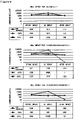
- the sample according to the sixth example which is produced by co-extrusion molding with an acrylic based thermoplastic elastomer in use for the material of a core layer and a fluorine based resin in use for the material of a first clad layer, is more insusceptible to damage in appearances due to impact and is harder to invite the deterioration of the luminance of the emitted light than the samples according to Comparison Examples 4 and 5 which are produced according to the other materials and methods.
- a circumferentially light-emitting type thermoplastic resin molded body according to the present invention is excellent in light emitting performance and shock-proof property besides the fact that it can be flexibly bent for use according to the type of optical ornaments or the shape of an object to be decorated and allows the overall luminance of the emitted light to improve in such a manner that it restrains the luminescent color from being yellowed at the distal locations of such body with regard to the light source, so that it is especially or preferably applicable to a light guiding rod.
- Such light guiding rod is applicable to car interior illumination devices such as auxiliary lamps around an instrument panel, around a car audio and navigation system and those installed on a door panel, a console box and pillars. Besides, it is applicable to a courtesy lamp, a map lamp, a room lamp, a floor lamp, a foot lamp, a ceiling lamp and a door lamp.
- such light guiding rod is also applicable to car exterior illumination devices such as a headlamp, a tail lamp, a brake lamp, a side marker lamp and a number plate lamp.
- car exterior illumination devices such as a headlamp, a tail lamp, a brake lamp, a side marker lamp and a number plate lamp.
- solar energy transmission systems such optical signal transmission systems as on-board, cellular or FA equipment wiring and to such optical sensors as a liquid level sensor and a pressure-sensitive sensor as well as to image guide means such as endoscopes and light guide means for optical equipment.
- such light guiding rod is also preferably applicable to luminaries and lamps for mobile phones, digital cameras, wristwatches, vertical pinball machines ('pachinko' in Japanese), slot machines, automatic vending machines, collars for dogs, decoration items, traffic signs, washbasins, showers, temperature indicators of bathtubs, OA equipment, electric home appliances, optical equipment, various types of building materials, stairs, banisters, railway platforms, outdoor signs, barrier-free spaces as well as to backlights of liquid crystal displays, light guides for variable message boards and for IR and/or UV blocking illuminations exclusively dedicated for art and history museums. Further, such light guiding rod may be used as lighting devices for various types of illuminations and lighting facility with such rod combined with light sources.
Landscapes
- Physics & Mathematics (AREA)
- General Physics & Mathematics (AREA)
- Engineering & Computer Science (AREA)
- Optics & Photonics (AREA)
- General Engineering & Computer Science (AREA)
- Theoretical Computer Science (AREA)
- Laminated Bodies (AREA)
- Light Guides In General And Applications Therefor (AREA)
- Planar Illumination Modules (AREA)
- Led Device Packages (AREA)
- Optical Fibers, Optical Fiber Cores, And Optical Fiber Bundles (AREA)
Description
- The present invention relates to improvement on a circumferentially light-emitting type thermoplastic resin molded body, in detail, pertaining to such molded body as being readily and flexibly bent for use according to the shape of an object to be decorated or according to a linearly formed decorative letter and/or pattern; being excellent in light emitting performance; and restraining the luminescent color from being yellowed at the locations of such molded body distant away from the light source.
- In recent years, a linear light emitting element has been used for a number of optical ornaments such as ornamental fittings or illuminations and decorative signs, in which the neon lamps having been used in the form of a linear light emitting element since before are essentially made of a glass tube poor at flexibility, so that there is no bending the same along the curved portion of a wall or drawing a decorative letter or pattern with the same.
- Thus, conventionally, such a light guiding rod has been developed as being made from plastic; light being emitted from its circumferential surface; and serving as a linear light emitting element with light made incident at the edge face thereof (refer to the disclosures of
Documents 1 to 3 below), but adopting a transparent resin higher in flexural modulus of elasticity for the material of the core layer problematically leads to making such rod so rigid that it cannot be bent to a great extent for practical use. - As a countermeasure, the present applicant has developed a flexible light guiding rod and applied for patent in which an acryl based thermoplastic elastomer is adopted for the material of the core layer, but there is much to be desired on the light emitting performance thereof and it necessitates a means to suppress the yellowing of the luminescent color (the phenomenon in which the luminescent color becomes tinted with yellow. i.e. it turns yellower at the farther locations from the light source).
- On the other hand, conventionally, in order to restrain the light emitted from the light guiding rod from being yellowed, such a technique has been known as a small amount of bluing agent being added to the resin materials from which the core layer and the clad layer are made so as to make the light emitted from such rod somewhat bluish, but such a technique as controlling chromaticity shift of the luminescent color from the proximal to distal locations of such rod with regard to the light source to the minimum has not been known.
- Document 1:
Japanese Patent Unexamined Application Publication No.2000-131530 - Document 2:
Japanese Patent Unexamined Application Publication No.2009-276651 - Document 3:
Japanese Patent Unexamined Application Publication No.2013-57924 - In view of the foregoing prior issues, the present invention is to provide a circumferentially light-emitting type thermoplastic resin molded body which can be flexibly bent for use according to the type of optical ornaments or the shape of an object to be decorated and which allows the overall luminance of the emitted light to improve and restrains the luminescent color from being yellowed at the distal locations of such body with regard to the light source.
- The means adopted herein to solve the above issues is explained with reference to the accompanying drawings.
- Specifically, in the preamble reciting a thermoplastic resin molded body comprising at least a
core layer 1 made from a thermoplastic elastomer; and a firstclad layer 2 made from a thermoplastic resin whose refractive index is smaller than that of the thermoplastic elastomer from which the core layer is made, the present invention is characterized in that a light diffusing agent is added to the thermoplastic elastomer from which thecore layer 1 is made and the thermoplastic resin from which thefirst clad layer 2 is made respectively; and the total light transmittance of thefirst clad layer 2 is defined as less than 70%, wherein a secondclad layer 3 which is made from the same resin material as that of the firstclad layer 2 and to which the light diffusing agent is not added is formed between thecore layer 1 and the firstclad layer 2, - wherein a proportional ratio of a thickness of the second
clad layer 3 to that of the firstclad layer 2 ranges from 50% to 150%; a total thickness of the first and secondclad layers first clad layer 2 is made ranges from 0.05 to 1.5%, and - wherein a proportional ratio by weight of the light diffusing agent added to the thermoplastic elastomer from which the
core layer 1 is made ranges from 0.5ppm to 10ppm. - Moreover, in order to restrain the luminescent color from being yellowed, it is preferred that the proportional ratio by weight of a bluing agent added to the thermoplastic elastomer from which the
core layer 1 is made range from 0.1ppm to 10ppm. The 'bluing agent' referred to herein denotes a blue or purple coloring agent to absorb visible light over the yellow wavelength range. - In addition, according to the present invention, in order to enhance the light emitting performance, it is preferred that the thickness of the
first clad layer 2 range from 0.1 to 0.3mm. - Further, in order to make the thermoplastic resin molded body excellent in light emitting performance and shock-proof property, it is preferred that an acryl based thermoplastic elastomer be adopted for the material of the
core layer 1 and a fluorine based resin be adopted for the material of thefirst clad layer 2. - In addition, according to the present invention, in order to make the thermoplastic resin molded body excellent in light emitting performance, it is preferred that titanium oxide or barium sulfate be adopted for the light diffusing agent which is added to the
core layer 1 and the firstclad layer 2. - According to the present invention disclosing a thermoplastic resin molded body from the circumferential surface of which light is emitted, by adopting an acryl based thermoplastic elastomer for the material of the core layer, it allows a flexible light guiding rod to be formed, which enables such rod to be fixed to an object to be decorated with the same bent to a large extent and such rod to be formed into a decorative letter or pattern. This leads to enlarging the scope of applications of such light guiding rod which have been unavailable before.
- As to the thermoplastic resin molded body according to the present invention, such arrangement that the light diffusing agent is added to the respective resin materials of the core layer and the clad layer allows the luminance of the light guiding rod as a whole to largely improve as well as the chromaticity shift (transition from white to yellow) of the luminescent color experienced from the proximal section of the light source to the distal section thereof to be restrained to the minimum so as to suppress the luminescent color from being yellowed.
- Accordingly, with the thermoplastic resin molded body of the present invention, it not only leads to solving the flexibility problem with the prior light guiding rod from the circumferential surface of which light is emitted, but also opts for decorative and display applications because its light emitting performance and color unevenness are improved through the favorable action of the light diffusing agent added to the core and clad layers, so that its industrial applicability is considered very high.
-
-
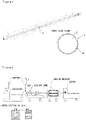
Figure 1 is a perspective view showing a thermoplastic resin molded body as a whole according to the present disclosure. -
Figure 2 is an explanatory view showing the steps of producing the thermoplastic resin molded body according to the present disclosure. -
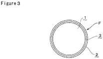
Figure 3 is an enlarged edge side view of the thermoplastic resin molded body according to the present invention. -
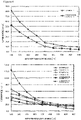
Figure 4 is a graph showing the luminance test results of the thermoplastic resin molded bodies according to the present invention. -
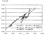
Figure 5 is a graph showing the chromaticity shift results in luminescent color of the thermoplastic resin molded bodies according to the present invention and comparison examples. -
Figure 6 illustrates graphs showing the test results on shock-proof property of the sampled thermoplastic resin molded body according to the present invention and according to comparison examples by each sample. -
Figure 7 illustrates graphs showing the test results on shock-proof property of the sampled thermoplastic resin molded body according to the present invention and those according to comparison examples under different temperature conditions. - A thermoplastic resin molded body is explained with reference to
Figures 1 and 2 , in which a thermoplastic resin molded body from the circumferential surface of which light is emitted, a core layer and a first clad layer are denoted as reference signs F, 1 and 2 respectively. - According to the present disclosure, as illustrated in
Figure 1 , the thermoplastic resin molded body F of a flexible light guiding rod type is constituted by forming the firstclad layer 2 made from a thermoplastic resin whose refractive index is smaller than that of the thermoplastic elastomer from which thecore layer 1 is made around the periphery of thecore layer 1. Further, it is arranged herein such that the predetermined amount of a light diffusing agent is added to the respective resin materials from which the core andclad layers first clad layer 2 is carried out such that the total light transmittance of the firstclad layer 2 is less than 70%. - As to the above thermoplastic resin molded body F, as illustrated in
Figure 1 , it is used in such a manner that light is emitted from the circumferential surface of such molded body F with a light source disposed at one end or both ends thereof and light made incident on the edge side thereof. Since the predetermined amount of the light diffusing agent is added to the core andclad layers - Then, the respective components of the above thermoplastic resin molded body F are explained as follows. To begin with, an acryl based thermoplastic elastomer is adopted for the material of the
core layer 1. Specifically speaking, it is preferred that an acryl based block copolymer, in which a polymer block (al) mainly consisting of a methacrylic acid ester unit is bonded to each extreme end of a polymer block (a2) essentially consisting of an acrylic acid ester unit or which has at least the structure (al)-(a2)-(al), in which the hyphen denotes a chemical bond, be adopted for the acryl based thermoplastic elastomer. The molecular weights and compositions of the polymer blocks (a1) at both ends of the polymer block (a2) may be the same or different between them. Further, the acryl based block copolymer may include a diblock copolymer expressed with (al)-(a2). - To note, methyl methacrylate and the like are exemplified herein for methacrylic acid ester from which the methacrylic acid ester unit is derived, in which such unit may comprise one type of or two or more types of those methacrylic acid esters.
- Further, methyl acrylate, n-butyl acrylate, benzyl acrylate and the like are exemplified herein for acrylic acid ester from which the acrylic acid ester unit is derived, in which such unit may comprise one type of or two or more types of those acrylic acid esters and it is preferred that such unit comprise n-butyl acrylate, benzyl acrylate or n-butyl acrylate and benzyl acrylate. In case where such unit comprises the copolymer of n-butyl acrylate and benzyl acrylate, it is preferred that the proportional ratio by mass of n-butyl acrylate to benzyl acrylate be from 50/50 to 90/10, in which it is more preferable that such ratio range from 60/40 to 80/20.
- Then, it is preferred that a block copolymer of methyl methacrylate and butyl acrylate (hereinafter, referred to as MMA-BA block copolymer), the flexural modulus of elasticity according to ASTM D790 of which ranges from 50 to 500MPa, be adopted for the material of the core layer. In this regard, taken co-extrusion molding with the
first clad layer 2 during production into account, it is preferred that a resin whose MFR (Melt Flow Rate) under the test conditions of the temperature of 190°C and the load of 5kg ranges from 2 to 10g/10min be adopted for the material of thecore layer 1. - It is preferred that a fluorine based resin whose refractive index is smaller than that of the
core layer 1 be adopted for the material of thefirst clad layer 2, in which ETFE (copolymer of ethylene and tetrafluoroethylene) and EFEP (terpolymer of hexafluoropropylene, tetrafluoroethylene and ethylene) are in use according to the present disclosure. However, other fluorine based resins such as PVDF (polyvinylidene difluoride) and the other resins are also adoptable for the same. In this regard, taken co-extrusion molding with thecore layer 1 during production into account, it is preferred that a resin whose melting point is at 230°C or lower be adopted for the material of the firstclad layer 2. - When PVDF is adopted for the material of the first
clad layer 2, it has higher compatibility with the acryl based thermoplastic elastomer from which thecore layer 1 is made, so that there is a merit in that theclad layer 2 becomes hard to be peeled from thecore layer 1 during use. On the other hand, when ETFE is adopted for the material of the first clad layer, the elongation rate of ETFE (i.e. 350 to 450%) is larger than that of PVDF (i.e.200 to 300%) while the flexural modulus of elasticity of ETFE (i.e.800 to 1000MPa) is smaller than that of PVDF (i.e.1400 to 1800MPa), so that wrinkles are hard to occur on the clad layer when the thermoplastic resin molded body F is bent. Further, ETFE is higher in visible light transmittance than PVDF, so that the attenuation rate of luminance can be minimized. To note, the respective numerical values of the above elongation rates are those measured according to ASTM D638 while the respective numerical values of the above flexural moduli of elasticity are those measured according to ASTM D790. - According to the present disclosure, titanium oxide in powdery form is adopted for the light diffusing agent to be added to the
core layer 1 and thefirst clad layer 2, but barium sulfate may be adopted for the same instead. As to the amount by which the light diffusing agent is added to thecore layer 1, it is preferred that the proportional ratio by weight of the light diffusing agent to the resin material from which thecore layer 1 is made range from 0.5ppm to 10ppm. In turn, when the thickness of thefirst clad layer 2 is defined as ranging from 0.1mm to 0.3mm (preferably ranging from 0.2mm to 0.3mm), it is preferred that the proportional ratio by weight of the light diffusing agent to the resin material from which thefirst clad layer 2 is made range from 0.05 to 1.5%. - According to the present disclosure, by adding a bluing agent (blue or purple pigment) to the
core layer 1, it restrains the luminescent color of the thermoplastic resin molded body F from being yellowed. As to the amount by which the bluing agent is added to the core layer, it is preferred that the proportional ratio by weight of the bluing agent to the resin material from which thecore layer 1 is made range from 0.1ppm to 10ppm. - According to the present disclosure, the thermoplastic resin molded body F is round bar-shaped in cross section, but may be angular or intricately bar-shaped in cross section. Further, it may take a plate-like shape whose aspect ratio is cross-sectionally large.
- Then, the method of producing a thermoplastic resin molded body F is explained as follows. As illustrated in
Figure 2 , after the core layer and the clad layer are simultaneously extruded from a die of an extruder and the integrated core and clad layers are subjected to cooling and shaping, the resulting thermoplastic resin molded body is cut into a prescribed length. Upon production, it is preferred that an acryl based thermoplastic elastomer whose MFR under the test conditions of the temperature of 190°C and under the load of 5kg ranges from 2 to 10g/10min be adopted for the material of the core layer while a fluorine based resin whose melting point is 230°C or lower be adopted for the material of the clad layer; and such layers be subjected to co-extrusion molding under the molding temperature of 270°C or lower. - Now, the present invention is explained with reference to
Figure 3 . What is denoted withnumeral reference 3 in the drawing is a second clad layer. In the present invention, a thermoplastic resin molded body F of a flexible light guiding rod type is constituted with the secondclad layer 3 interposed between thecore layer 1 and the firstclad layer 2. The light diffusing agent is added to the respective resin materials from which thecore layer 1 and the outer first cladlayer 2 are made. The same resin material as the firstclad layer 2 is adopted for the material of the secondclad layer 3, but the light diffusing agent is not added to the resin material from which the second clad layer is made. This arrangement allows the uniform light emitting performance of the thermoplastic resin molded body F to improve. - The conditions imposed upon selecting the resin material from which the
core layer 1 is made and those imposed upon selecting the resin material (the same resin material as the second clad layer 3) from which the firstclad layer 2 is made are the same as described above. Further, the material of the light diffusing agent and the conditions imposed upon production are also the same as described above. - On the other hand, as to the thickness of the clad layer, the proportional ratio of the second
clad layer 3 in thickness to the firstclad layer 2 ranges from 50% to 150% and the total thickness of the first and secondclad layers clad layer 2 formed in relation to the above total thickness is made such that the proportional ratio of the light diffusing agent by weight to the resin material from which the firstclad layer 2 is made ranges from 0.05 to 1.5% and the proportional ratio by weight of the light diffusing agent added to the thermoplastic elastomer from which the core layer is made ranges from 0.5ppm to 10ppm. In the present invention as well, it is preferred that the light diffusing agent be added to the firstclad layer 2 such that the total light transmittance of those two layers of the first and secondclad layers - Now, the verification test (i) on advantageous effects brought by the present invention is explained. In the first place, a plurality of samples (the following comparison examples 1 to 3 as well as the following examples 1 to 5) which are different from one another in production conditions (i.e. addition of the light diffusing agent and bluing agent to the core layer, an amount by which the light diffusing agent is added and constitution of the clad layer) are prepared and evaluation on light emitting performance (luminance of emitted light and attenuation rate) and chromaticity shift of the luminescent color is made on the respective samples. To note, in the present verification test, a powdery titanium oxide is adopted for the light diffusing agent. The production conditions of the comparison examples 1 to 3 and those of the first to fifth examples are as follows.
- In this example, a round bar-shaped thermoplastic resin molded body comprises a core layer and a first clad layer whose thickness is 0.24mm. The thermoplastic resin molded body is produced through co-extrusion molding by adopting an MMA-BA block copolymer whose MFR under the test conditions of the temperature of 190°C and the load of 2.16kg is 3.1g/10min and whose flexural modulus of elasticity is 400MPa for the material of the core layer while by adopting an ETFE whose melting point, elongation rate, flexural modulus of elasticity and MFR under the test conditions of the temperature of 297°C andthe load of 5kg are 192°C, 417%, 959MPa and 78.6g/10min respectively for the material of the first clad layer. The light diffusing agent is not added to the core layer, but only to the first clad layer such that the proportional ratio of the light diffusing agent by weight to the resin material from which the first clad layer is made is 0.065%. It is found that the total light transmittance of the first clad layer is 65.2%.
- In this example, a round bar-shaped thermoplastic resin molded body comprises a core layer, a second clad layer whose thickness is 0.1mm and a first clad layer whose thickness is 0.11mm. The thermoplastic resin molded body is produced through co-extrusion molding by adopting the same MMA-BA block copolymer as the comparison example 1 for the material of the core layer while by adopting the same ETFE as the first clad layer according to the comparison example 1 for the material of the second and first clad layers respectively. The light diffusing agent is not added to the core layer, but only to the first clad layer such that the proportional ratio of the light diffusing agent by weight to the resin material from which the first clad layer is made is 1.3%. It is found that the total light transmittance of those two layers of first and second clad layers is 24.5%.
- This example is the same as the comparison example 2 except that blue and purple pigments which are bluing agents are added to the resin material from which the core layer is made such that the proportional ratio of the respective pigments by weight to the resin material from which the core layer is made is 1ppm and an antioxidant is added to the resin material from which the core layer is made such that the proportional ratio of the antioxidant by weight to the resin material from which the core layer is made is 0.1%. The total light transmittance of those two layers of first and second clad layers turns out to be 24.5%.
- In this example, a round bar-shaped thermoplastic resin molded body comprises a core layer and a first clad layer whose thickness is 0.24mm. The thermoplastic resin molded body is produced through co-extrusion molding by adopting an MMA-BA block copolymer whose MFR under the test conditions of the temperature of 190°C and the load of 2.16kg is 3.1 g/10min and whose flexural modulus of elasticity is 400MPa for the material of the core layer while by adopting an ETFE whose melting point, elongation rate, flexural modulus of elasticity and MFR under the test conditions of the temperature of 297°C and the load of 5kg are 192°C, 417%, 959MPa and 78.6g/10min respectively for the material of the first clad layer.
- The light diffusing agent is added to the core layer such that the proportional ratio of the light diffusing agent by weight to the resin material from which the core layer is made is 1ppm. On the other hand, the light diffusing agent is added to the first clad layer such that the proportional ratio of the light diffusing agent by weight to the resin material from which the first clad layer is made is 0.065%. Blue and purple pigments which are bluing agents are added to the core layer such that the proportional ratio of the respective pigments by weight to the resin material from which the core layer is made is 1ppm while an antioxidant is added to the core layer such that the proportional ratio of the antioxidant by weight to the resin material from which the core layer is made is 0.1%. The total light transmittance of the first clad layer turns out to be 65.2%.
- In this example, a round bar-shaped thermoplastic resin molded body comprises a core layer, a second clad layer whose thickness is 0.1mm and a first clad layer whose thickness is 0.12mm. The thermoplastic resin molded body is produced through co-extrusion molding by adopting the same MMA-BA block copolymer as the first example for the material of the core layer while by adopting the same ETFE as the first clad layer according to the first example for the material of the second and first clad layers respectively. The light diffusing agent is added to the core layer such that the proportional ratio of the light diffusing agent by weight to the resin material from which the core layer is made is 0.5ppm.
- On the other hand, the light diffusing agent is not added to the second clad layer, but only to the first clad layer such that the proportional ratio of the light diffusing agent by weight to the resin material of the first clad layer is 1.3%. Blue and purple pigments which are bluing agents are added to the core layer such that the proportional ratio of the respective pigments by weight to the resin material from which the core layer is made is 1ppm while an antioxidant is added to the core layer such that the proportional ratio of the antioxidant by weight to the resin material from which the core layer is made is 0.1%. The total light transmittance of those two layers of first and second clad layers turns out to be 18.2%.
- This example is the same as the second example except that the light diffusing agent is added to the core layer such that the proportional ratio of the light diffusing agent by weight to the resin material from which the core layer is made is 0.8ppm.
- This example is the same as the second example except that the light diffusing agent is added to the core layer such that the proportional ratio of the light diffusing agent by weight to the resin material from which the core layer is made is 1ppm.
- This example is the same as the second example except that the proportional ratio of the light diffusing agent by weight to the resin material from which the core layer is made is 3ppm.
- The production conditions of the comparison examples 1 to 3 as well as those of the first to fifth examples are summarized in the following table.
[Table 1] First Example∗ Second Example Third Example Fourth Example Fifth Example Comp.Ex.1 Comp.Ex.2 Comp.Ex.3 Core Layer Material MMA-BA Block Copolymer Light Diffusing Agent 1ppm 0.5ppm 0.8ppm 1ppm 3ppm N/A N/A N/A Bluing Agent (Blue Pigment) 1ppm 1ppm 1ppm 1ppm 1ppm N/A N/A 1ppm Bluing Agent (Purple Pigment) 1ppm 1ppm 1ppm 1ppm 1ppm N/A N/A 1ppm Antioxidant 0.1% 0.1% 0.1% 0.1% 0.1% N/A N/A 0.1% Second Clad layer Material N/A ETFE ETFE ETFE ETFE N/A ETFE ETFE Thickness N/A 0.1mm 0.1mm 0.1mm 0.1mm N/A 0.1mm 0.1mm First Clad Layer Material ETFE ETFE ETFE ETFE ETFE ETFE ETFE ETFE Light Diffusing Agent 0.065% 1.3% 1.3% 1.3% 1.3% 0.065% 1.3% 1.3% Thickness 0.24mm 0.12mm 0.12mm 0.12mm 0.12mm 0.24mm 0.11mm 0.11mm Total Light Transmittance of Clad Layer (s) 65.2% 18.2% 18.2% 18.2% 18.2% 65.2% 24.5% 24.5% ∗Reference Example - Then, as for each sample of the comparison examples 1 to 3 as well as the first to fifth examples, the luminance of each sample having 1000mm in length and 6.3mm in diameter is measured every 100mm at the distances from the light source ranging from 100 to 900mm. To note, the present evaluation is made in such a manner that a spectral radiance meter (manufactured by Konica Minolta, Inc. under the product name of CS-2000) is disposed at a location distant away by 600mm in the vertical direction from a portion of each sample to be measured. The specification of the light source in use is as follows: driving current at 20mA; 25cd/m2 in luminance; and directivity at 30 degrees. The measuring conditions are summarized in the following Table 2.
[Table2] Measuring Device Spectral Radiance Meter CS-2000 (manufactured by Konica Minolta, Inc.) Specification of Light Source Driving Current 20mA Luminance 25cd/m2 Directivity 30 degrees Sample Diameter [mm] Ø6.3 Sample Length [mm] 1000 Distance from Sample [mm] 600 Measuring Range [mm] 100 to 900 - Then, as seen from
Figure 4 in which the measuring results are represented with graphs, in the case of the provision of one clad layer, it is confirmed that the overall luminance of the thermoplastic resin molded body according to the first example is larger than that of the counterpart according to the comparison example 1. Further, also in the case of the provision of two clad layers, it is confirmed that the luminance of each sample according to the second to fifth examples is larger than that of the counterparts according to the comparison examples 2 and 3. The detailed data on the luminance (unit of luminance: cd/m2) and attenuation rate of each sample are summarized in the following table.

- As the result of checking chromaticity shift of luminescent color from the proximal side to the distal side with respect to the light source for each sample according to the comparison examples 1 to 3 as well as according to the first to fifth examples, as illustrated in
Figure 5 , in the case of the provision of one clad layer, it is confirmed that yellowing of the luminescent color of the thermoplastic resin molded body according to the first example is further suppressed than that of the counterpart according to the comparison example 1. Also in the case of the provision of two clad layers, it is confirmed that yellowing of the luminescent color according to each sample of the second to fifth examples is further suppressed than that according to each sample of the comparison examples 2 and 3. - To note, the above evaluation on chromaticity shift of luminescent color is made for each sample such that the luminescent color at the distances from the light source ranging from 100 to 900mm is measured every 100mm employing a CIE chromaticity diagram with largeness in shift from the minimum x and y values (coordinates lopsided to bluing) to the maximum x and y values (coordinates lopsided to yellowing) compared. The detailed data on chromaticity shift for each sample are illustrated in the following table 4. As seen from Table 4, the x and y values proximal to the light source are minimum ones while those values distal from the light source are maximum ones excepting the sample according to the fifth example.
[Table 4] Sample Coordinate Distance from Light Source [mm] Chromaticity Shift 100 200 300 400 500 600 700 800 900 (MAX-MIN) First Example∗ x 0.2772 0.2779 0.2803 0.2809 0.2810 0.2815 0.2819 0.2822 0.2824 0.0052 y 0.2671 0.2681 0.2693 0.2719 02745 0.2763 0.2791 0.2847 0.2891 0.0220 Second Example x 0.2710 0.2717 0.2731 0.2739 0.2751 0.2768 0.2784 0.2789 0.2797 0.0087 y 0.2543 0.2555 0.2591 0.2633 0.2669 0.2678 0.2681 0.2683 0.2690 0.0147 Third Example x 0.2711 0.2722 0.2735 0.2739 0.2745 0.2752 0.2758 0.2763 0.2769 0.0058 y 0.2611 0.2641 0.2675 0.2675 0.2689 0.2711 0.2731 0.2749 0.2745 0.0138 Fourth Example x 0.2736 0.2732 0.2739 0.2739 0.2742 0.2747 0.2748 0.2754 0.2758 0.0026 y 0.2634 0.2639 0.2658 0.2669 0.2685 0.2705 0.2719 0.2740 0.2759 0.0125 Fifth Example x 0.2784 0.2771 0.2757 0.2745 0.2731 0.2720 0.2710 0.2698 0.2688 0.0096 y 0.2690 0.2688 0.2686 0.2686 0.2684 0.2686 02689 0.2691 0.2693 0.0009 Comparison Example 1 x 0.2751 0.2781 0.2799 0.2814 0.2831 0.2854 0.2879 0.2889 0.2901 0.0150 y 0.2631 0.2644 0.2690 0.2754 0.2789 0.2836 0.2867 0.2881 0.2922 0.0291 Comparison Example 2 x 0.2583 0.2565 0.2553 0.2571 0.2576 0.2598 0.2605 0.2624 0.2653 0.0100 y 0.2456 0.2442 0.2437 0.2470 0.2487 0.2525 0.2545 0.2579 0.2626 0.0189 Comparison Example 3 x 0.2504 0.2514 0.2538 0.2580 0.2633 0.2678 0.2727 0.2779 0.2839 0.0335 y 0.2372 0.2396 0.2437 0.2499 0.2575 0.2641 0.2710 0.2781 0.2860 0.0488 ∗Reference Example - Explanation is given on the verification test (ii) on effects brought by the present invention as follows. In this verification test, a plurality of samples (according to the following comparison examples 4 and 5 and sixth example) whose materials for the core and clad layers and whose production methods are different from one another are produced and evaluation is made on each sample in terms of its light emitting performance (luminance of the emitted light) after it is subjected to ball impact test. To note, in this test, powdery titanium oxide is adopted for the light diffusing agent. The conditions under which each sample of the following comparison examples 4 and 5 and sixth example is produced are explained as follows.
- In this example, the circumferentially light-emitting type thermoplastic resin molded body is presented as a rod-shaped body which comprises a core layer and a first clad layer and whose outer diameter is 3.5mm. For the materials of the core layer, polyoxypropylenetriol and polyoxypropylenediol are adopted for polymerpolyol while hexamethylene diisocyanate being adopted for a multifunctional compound having reactivity to the hydroxyl group. In turn, tetrafluoroethylenehexafluoropropylene copolymer (FEP) is adopted for the material of the first clad layer. Then, the circumferentially light-emitting type thermoplastic resin molded body is produced with the mixture of the materials of the core layer filled in the tube comprising the first clad layer so as to be thermally cured.
- In this example, the circumferentially light-emitting type thermoplastic resin molded body is presented as a rod-shaped body which comprises a core layer and a first clad layer and whose outer diameter is 3.0mm. What is bis (4-t-butylcyclohexyl) peroxydicarbonate acting as polymerization initiator is added to a polymerizable monomer (a mixed liquid composed of n-butyl methacrylate and triethylene glycol dimethacrylate, in which the proportional ratio by weight between them is 100 to 1) is adopted for the materials of the core layer. A tetrafluoroethylenehexafluoropropylene copolymer is adopted for the material of the first clad layer. Then, a circumferentially light-emitting type thermoplastic resin molded body is produced with the materials of the core layer filled under pressure in the first clad layer molded into a tube shape with an extruder so as to be polymerized.
- In this example, a circumferentially light-emitting type thermoplastic resin molded body is presented as a rod-shaped body which comprises a core layer and a first clad layer and whose outer diameter is 3.5mm. The circumferentially light-emitting type thermoplastic resin molded body is produced through co-extrusion molding with in use MMA-BA block copolymer whose MFR under the test conditions of the temperature of 190°C and the load of 2.16kg and whose flexural modulus of elasticity are 3.1g/10min and 400 MPa respectively is adopted for the material of the core layer while ETFE whose melting point, elongation rate, flexural modulus of elasticity and MFR under the test conditions of the temperature of 297°C and the load of 5kg are 192°C, 417%, 959MPa and 78.6g/10min respectively being adopted for the material of the first clad layer.
- Then, the above-mentioned ball impact test is methodically explained as follows. In this test, after each sample cut into 200mm in length is left as it is for about three hours under the arbitrary temperatures (under the room temperature; under the temperature of -30°C; under the temperature of 80°C), impact is applied to the center portion of each sample with a steel ball (2.5 inches in diameter) having about 1040g in mass dropped onto such center portion from the height of 306mm. To note, the test is carried out with each sample placed on an iron plate whose thickness is about 30mm.
- Then, the method of evaluating the light emitting performance of each sample is explained as follows. The luminance of the emitted light of each sample subjected to the ball impact test is measured with respect to the center portion thereof before such ball is dropped thereon, at the very center portion where it has been dropped and with respect to the center portion thereof after it has been dropped thereon respectively. To note, the present evaluation test is made in such a manner that a spectral radiance meter (manufactured by Konica Minolta, Inc. under the product name of CS-2000) is disposed at a location distant away by 600mm in the vertical direction from a portion of each sample to be measured. The specification of the light source in use is as follows: driving current at 20mA; 25cd/m2 in luminance; and directivity at 30 degrees.
- As the result of measuring the luminance of each sample at the ball impact and before/after the ball impact respectively, as illustrated in
Figures 6 and7 , it is confirmed that the luminance of the emitted light of the sample according to the sixth example is significantly higher than that according to Comparison Example 4 in terms of the center portion thereof after such ball has been dropped thereon when reference is made to the result of each sample left under the temperature of -30°C and subjected to the ball impact test. Also in the aspect of appearances, after each sample being subjected to the ball impact test under the temperature of -30°C, as to the sample according to the sixth example, there occurs just a dimple at the very point where such ball has been dropped whereas as to the sample according to Comparison Example 4, a whitened smudge due to its internal damage appears at the very point where such ball has been dropped. - On the other hand, as to each sample subjected to the ball impact test under the temperature of 80°C, it is confirmed that the luminance of the emitted light of the sample according to the sixth example is significantly higher than that of Comparison Example 5 with respect to the center portion thereof after such ball has been dropped thereon. Also in the aspect of appearances, after each sample being subjected to the ball impact test under the temperature of 80°C, as to the sample according to the sixth example, there occurs just a dimple at the very point where such ball has been dropped whereas as to the sample according to Comparison Example 5, a whitened smudge due to its internal damage appears at the very point where such ball has been dropped.
- As the result of the above verification test (ii), it is confirmed that the sample according to the sixth example, which is produced by co-extrusion molding with an acrylic based thermoplastic elastomer in use for the material of a core layer and a fluorine based resin in use for the material of a first clad layer, is more insusceptible to damage in appearances due to impact and is harder to invite the deterioration of the luminance of the emitted light than the samples according to Comparison Examples 4 and 5 which are produced according to the other materials and methods.
- A circumferentially light-emitting type thermoplastic resin molded body according to the present invention is excellent in light emitting performance and shock-proof property besides the fact that it can be flexibly bent for use according to the type of optical ornaments or the shape of an object to be decorated and allows the overall luminance of the emitted light to improve in such a manner that it restrains the luminescent color from being yellowed at the distal locations of such body with regard to the light source, so that it is especially or preferably applicable to a light guiding rod.
- Such light guiding rod is applicable to car interior illumination devices such as auxiliary lamps around an instrument panel, around a car audio and navigation system and those installed on a door panel, a console box and pillars. Besides, it is applicable to a courtesy lamp, a map lamp, a room lamp, a floor lamp, a foot lamp, a ceiling lamp and a door lamp.
- Further, such light guiding rod is also applicable to car exterior illumination devices such as a headlamp, a tail lamp, a brake lamp, a side marker lamp and a number plate lamp. Moreover, it is also applicable to solar energy transmission systems, such optical signal transmission systems as on-board, cellular or FA equipment wiring and to such optical sensors as a liquid level sensor and a pressure-sensitive sensor as well as to image guide means such as endoscopes and light guide means for optical equipment.
- Besides, such light guiding rod is also preferably applicable to luminaries and lamps for mobile phones, digital cameras, wristwatches, vertical pinball machines ('pachinko' in Japanese), slot machines, automatic vending machines, collars for dogs, decoration items, traffic signs, washbasins, showers, temperature indicators of bathtubs, OA equipment, electric home appliances, optical equipment, various types of building materials, stairs, banisters, railway platforms, outdoor signs, barrier-free spaces as well as to backlights of liquid crystal displays, light guides for variable message boards and for IR and/or UV blocking illuminations exclusively dedicated for art and history museums. Further, such light guiding rod may be used as lighting devices for various types of illuminations and lighting facility with such rod combined with light sources.
-
- 1
- core layer
- 2
- first clad layer
- 3
- second clad layer
- F
- thermoplastic resin molded body
Claims (5)
- A circumferentially light-emitting type thermoplastic resin molded body (F) at least comprising a core layer (1) made from a thermoplastic elastomer; and a first clad layer (2) made from a thermoplastic resin whose refractive index is smaller than that of the thermoplastic elastomer from which the core layer (1) is made,wherein a light diffusing agent is added to the thermoplastic resin from which the first clad layer (2) is made respectively;and a total light transmittance of the first clad layer (2) is defined as less than 70%,wherein a second clad layer (3) which is made from the same resin material as that of the first clad layer (2) and to which the light diffusing agent is not added is formed between the core layer (1) and the first clad layer (2),wherein a total thickness of the first and second clad layers (2) and (3) ranges from 0.15 mm to 0.4 mm; and the proportional ratio by weight of the light diffusing agent added to the resin material from which the first clad layer (2) is made ranges from 0.05 to 1.5%,characterised in thata light diffusing agent is added to the thermoplastic elastomer from which the core layer (1) is made;a proportional ratio of a thickness of the second clad layer (3) to that of the first clad layer (2) ranges from 50% to 150%; anda proportional ratio by weight of the light diffusing agent added to the thermoplastic elastomer from which the core layer (1) is made ranges from 0.5ppm to 10ppm.
- The circumferentially light-emitting type thermoplastic resin molded body (F) according to claim 1, wherein a proportional ratio by weight of a bluing agent added to the thermoplastic elastomer from which the core layer (1) is made ranges from 0.1ppm to 10ppm.
- The circumferentially light-emitting type thermoplastic resin molded body (F) according to claim 1 or 2, wherein a thickness of the first clad layer (2) ranges from 0.1 to 0.3mm.
- The circumferentially light-emitting type thermoplastic resin molded body (F) according to any one of claims 1 to 3, wherein an acryl based thermoplastic elastomer is adopted for the material of the core layer (1) and a fluorine based resin is adopted for the material of the first clad layer (2).
- The circumferentially light-emitting type thermoplastic resin molded body (F) according to any one of claims 1 to 4, wherein one of titanium oxide and barium sulfate is adopted for the light diffusing agent added to the core layer (1) and the first clad layer (2).
Applications Claiming Priority (2)
| Application Number | Priority Date | Filing Date | Title |
|---|---|---|---|
| JP2017013681 | 2017-03-31 | ||
| PCT/JP2018/010622 WO2018180644A1 (en) | 2017-03-31 | 2018-03-16 | Thermoplastic resin molding of peripheral surface light-emitting type |
Publications (3)
| Publication Number | Publication Date |
|---|---|
| EP3605170A1 EP3605170A1 (en) | 2020-02-05 |
| EP3605170A4 EP3605170A4 (en) | 2020-06-03 |
| EP3605170B1 true EP3605170B1 (en) | 2022-12-28 |
Family
ID=63675549
Family Applications (1)
| Application Number | Title | Priority Date | Filing Date |
|---|---|---|---|
| EP18776795.9A Active EP3605170B1 (en) | 2017-03-31 | 2018-03-16 | Thermoplastic resin molding of peripheral surface light-emitting type |
Country Status (8)
| Country | Link |
|---|---|
| US (1) | US11086062B2 (en) |
| EP (1) | EP3605170B1 (en) |
| JP (1) | JP7083336B2 (en) |
| KR (1) | KR20190129037A (en) |
| CN (1) | CN110383125A (en) |
| CA (1) | CA3058090C (en) |
| ES (1) | ES2937909T3 (en) |
| WO (1) | WO2018180644A1 (en) |
Families Citing this family (5)
| Publication number | Priority date | Publication date | Assignee | Title |
|---|---|---|---|---|
| WO2020145107A1 (en) * | 2019-01-09 | 2020-07-16 | フクビ化学工業株式会社 | Peripheral surface light emitting-type light guide bar |
| JP2020112617A (en) * | 2019-01-09 | 2020-07-27 | フクビ化学工業株式会社 | Light guide rod of peripheral surface light-emitting type |
| JP2020112616A (en) * | 2019-01-09 | 2020-07-27 | フクビ化学工業株式会社 | Light guide rod of peripheral surface light-emitting type |
| JP7175823B2 (en) * | 2019-03-28 | 2022-11-21 | フクビ化学工業株式会社 | Peripheral light-emitting type light guide bar |
| JP7468302B2 (en) | 2020-11-05 | 2024-04-16 | 東レ株式会社 | Illuminated plastic optical fiber and illuminated plastic optical fiber cord |
Family Cites Families (31)
| Publication number | Priority date | Publication date | Assignee | Title |
|---|---|---|---|---|
| JPH09325221A (en) * | 1996-04-04 | 1997-12-16 | Hitachi Cable Ltd | Lighting device |
| US6366727B1 (en) * | 1996-11-07 | 2002-04-02 | 3M Innovative Properties Company | Light-illuminating rods |
| US6123442A (en) * | 1997-10-24 | 2000-09-26 | Minnesota Mining And Manufacturing Company | Articles with diffuse reflection of light from light fibers |
| US6091878A (en) * | 1997-11-20 | 2000-07-18 | Rohm And Haas Company | Flexible light pipe for side-lit applications |
| JPH11326644A (en) * | 1998-05-20 | 1999-11-26 | Bridgestone Corp | Light transmission tube and its production |
| US6519401B1 (en) * | 1998-10-28 | 2003-02-11 | 3M Innovative Properties Company | Light fibers and methods for producing the same |
| JP4740431B2 (en) | 1998-10-28 | 2011-08-03 | スリーエム カンパニー | Optical fiber and manufacturing method thereof |
| US6236460B1 (en) * | 1999-01-29 | 2001-05-22 | E. I. Du Pont De Nemours And Company | Method to determine light scattering efficiency of pigments |
| JP3998502B2 (en) * | 2002-04-05 | 2007-10-31 | スリーエム イノベイティブ プロパティズ カンパニー | Gaze guidance lighting device |
| JP2004342411A (en) * | 2003-05-14 | 2004-12-02 | Sharp Corp | Illuminating device and illuminating system including the same |
| TW200621484A (en) * | 2004-10-28 | 2006-07-01 | Fuji Photo Film Co Ltd | Plastic optical member and producing method thereof |
| JP2006317844A (en) * | 2005-05-16 | 2006-11-24 | Three M Innovative Properties Co | Side emission optical fiber and light emitting apparatus |
| FR2891455A1 (en) * | 2005-09-30 | 2007-04-06 | Fabre Pierre Dermo Cosmetique | Oblong particles in the form of a pile made up of a organogellifying fibers in xerogel form, useful e.g. in dermo-cosmetic composition e.g. to hide wrinkles, ridules and cutaneous imperfections |
| WO2007055390A1 (en) * | 2005-11-10 | 2007-05-18 | Teijin Chemicals Ltd. | Optical device and achromatic lens |
| JP2009059583A (en) * | 2007-08-31 | 2009-03-19 | Mitsubishi Rayon Co Ltd | Side-face light leakage illuminating device |
| JP5341391B2 (en) * | 2008-05-16 | 2013-11-13 | スリーエム イノベイティブ プロパティズ カンパニー | Side-emitting optical fiber |
| US20110148661A1 (en) | 2008-07-02 | 2011-06-23 | Shinichi Shikii | Guiding device |
| JP5476027B2 (en) * | 2009-04-16 | 2014-04-23 | ダイセルポリマー株式会社 | AS resin composition |
| US8634687B2 (en) * | 2009-10-19 | 2014-01-21 | Sumitomo Electric Industries, Ltd. | Coated plastic cladding optical fiber and optical fiber cable |
| US8331750B2 (en) * | 2010-02-01 | 2012-12-11 | Enlighting Inc | Optical fibers having a surface light field emulation (s-LiFE) segment and method of making the same |
| JP2012103618A (en) * | 2010-11-12 | 2012-05-31 | Sekisui Chem Co Ltd | Light diffusing rod |
| JP2012103617A (en) | 2010-11-12 | 2012-05-31 | Sekisui Chem Co Ltd | Light diffusing rod and manufacturing method thereof |
| CN102673024A (en) * | 2011-03-11 | 2012-09-19 | 北京君鹏鑫新技术开发有限公司 | Linear luminous body and manufacturing method thereof |
| JP5885196B2 (en) * | 2011-08-18 | 2016-03-15 | フクビ化学工業株式会社 | Manufacturing method of optical fiber type linear light emitter, and optical fiber type linear light emitter |
| JP5854260B2 (en) | 2011-09-07 | 2016-02-09 | 三菱レイヨン株式会社 | Light guide for surface light source device, manufacturing method thereof, and surface light source device |
| US9075213B2 (en) * | 2011-09-14 | 2015-07-07 | Mitsubishi Rayon Co., Ltd. | Plastic optical fiber cable |
| JP6342813B2 (en) * | 2011-12-19 | 2018-06-13 | コーニング インコーポレイテッド | High efficiency uniform UV light diffusing fiber |
| JP5888788B2 (en) * | 2013-09-27 | 2016-03-22 | フクビ化学工業株式会社 | Linear illuminant and method for producing the same |
| JP2017536571A (en) | 2014-10-23 | 2017-12-07 | コーニング インコーポレイテッド | Light diffusing optical fiber with nanostructured inner and outer core regions |
| WO2016190138A1 (en) | 2015-05-22 | 2016-12-01 | 株式会社クラレ | Acrylic block copolymer, resin composition and molded body comprising same, and optical member |
| US10197722B2 (en) * | 2015-09-02 | 2019-02-05 | Fukuvi Chemical Industry Co., Ltd. | Flexible linear light emitting element and a method of producing the same |
-
2018
- 2018-03-16 CA CA3058090A patent/CA3058090C/en active Active
- 2018-03-16 WO PCT/JP2018/010622 patent/WO2018180644A1/en active Application Filing
- 2018-03-16 KR KR1020197025701A patent/KR20190129037A/en not_active Application Discontinuation
- 2018-03-16 US US16/494,669 patent/US11086062B2/en active Active
- 2018-03-16 JP JP2019509312A patent/JP7083336B2/en active Active
- 2018-03-16 EP EP18776795.9A patent/EP3605170B1/en active Active
- 2018-03-16 CN CN201880016018.7A patent/CN110383125A/en active Pending
- 2018-03-16 ES ES18776795T patent/ES2937909T3/en active Active
Also Published As
| Publication number | Publication date |
|---|---|
| US11086062B2 (en) | 2021-08-10 |
| KR20190129037A (en) | 2019-11-19 |
| CA3058090C (en) | 2023-01-03 |
| EP3605170A1 (en) | 2020-02-05 |
| ES2937909T3 (en) | 2023-04-03 |
| CA3058090A1 (en) | 2018-10-04 |
| CN110383125A (en) | 2019-10-25 |
| JPWO2018180644A1 (en) | 2020-02-06 |
| WO2018180644A1 (en) | 2018-10-04 |
| US20200018884A1 (en) | 2020-01-16 |
| JP7083336B2 (en) | 2022-06-10 |
| EP3605170A4 (en) | 2020-06-03 |
Similar Documents
| Publication | Publication Date | Title |
|---|---|---|
| EP3605170B1 (en) | Thermoplastic resin molding of peripheral surface light-emitting type | |
| TWI599608B (en) | Methacrylic resin composition | |
| JP2646193B2 (en) | Cured composite material and method for producing the same | |
| TWI749173B (en) | Resin composition containing acrylic block copolymer and light diffusing agent | |
| JP4203985B2 (en) | Illumination lighting device | |
| CN104035144A (en) | Film for improving color display and method for manufacturing the same, and display apparatus | |
| CN107924021B (en) | Soft linear luminous body and method for manufacturing same | |
| US20090311512A1 (en) | Radiation-Emitting Component | |
| CN107614556A (en) | Acrylic block copolymer and the resin combination, formed body and optical component for including it | |
| KR20140121176A (en) | Window for display device and display device including the window | |
| CN103988099A (en) | Optical film and optical display device including same | |
| JP5436384B2 (en) | Luminous body | |
| KR101528653B1 (en) | Light Guide Plate and Backlight Unit Assembly | |
| JP6387727B2 (en) | Luminescent transparent resin composition and molded body thereof | |
| KR20150086663A (en) | Optical film | |
| CN114096608B (en) | Methacrylic resin composition, molded article thereof, and method for producing film | |
| KR101653051B1 (en) | Lateral emitting optical fiber | |
| JP4928760B2 (en) | LIGHT TRANSMITTER AND LIGHTING DEVICE USING THE LIGHT TRANSMITTER | |
| JP6013814B2 (en) | A method for manufacturing an optical transmitter and a method for manufacturing a lighting device. | |
| US20170336048A1 (en) | Fluorescent diffusion board for lighting | |
| JP2005275019A (en) | Light-transmitting body and lighting system using the same | |
| JP2008268292A (en) | Optical transmission member and lighting device using the same | |
| JP2017083737A (en) | Optical transmission member and method for forming the member | |
| KR20170003183A (en) | Transparent Plastic Sheet And Liquid Crystal Display Device Including The Same As A Front Sheet |
Legal Events
| Date | Code | Title | Description |
|---|---|---|---|
| STAA | Information on the status of an ep patent application or granted ep patent |
Free format text: STATUS: THE INTERNATIONAL PUBLICATION HAS BEEN MADE |
|
| PUAI | Public reference made under article 153(3) epc to a published international application that has entered the european phase |
Free format text: ORIGINAL CODE: 0009012 |
|
| STAA | Information on the status of an ep patent application or granted ep patent |
Free format text: STATUS: REQUEST FOR EXAMINATION WAS MADE |
|
| 17P | Request for examination filed |
Effective date: 20191024 |
|
| AK | Designated contracting states |
Kind code of ref document: A1 Designated state(s): AL AT BE BG CH CY CZ DE DK EE ES FI FR GB GR HR HU IE IS IT LI LT LU LV MC MK MT NL NO PL PT RO RS SE SI SK SM TR |
|
| AX | Request for extension of the european patent |
Extension state: BA ME |
|
| A4 | Supplementary search report drawn up and despatched |
Effective date: 20200508 |
|
| RIC1 | Information provided on ipc code assigned before grant |
Ipc: G09F 13/00 20060101ALI20200501BHEP Ipc: G02B 6/02 20060101ALI20200501BHEP Ipc: F21V 8/00 20060101ALI20200501BHEP Ipc: G02B 6/00 20060101AFI20200501BHEP Ipc: F21K 9/61 20160101ALI20200501BHEP Ipc: G02B 6/036 20060101ALI20200501BHEP |
|
| DAV | Request for validation of the european patent (deleted) | ||
| DAX | Request for extension of the european patent (deleted) | ||
| STAA | Information on the status of an ep patent application or granted ep patent |
Free format text: STATUS: EXAMINATION IS IN PROGRESS |
|
| 17Q | First examination report despatched |
Effective date: 20210616 |
|
| GRAP | Despatch of communication of intention to grant a patent |
Free format text: ORIGINAL CODE: EPIDOSNIGR1 |
|
| STAA | Information on the status of an ep patent application or granted ep patent |
Free format text: STATUS: GRANT OF PATENT IS INTENDED |
|
| RIC1 | Information provided on ipc code assigned before grant |
Ipc: F21Y 101/00 20160101ALN20220629BHEP Ipc: F21S 43/20 20180101ALN20220629BHEP Ipc: F21S 43/247 20180101ALN20220629BHEP Ipc: F21S 43/245 20180101ALN20220629BHEP Ipc: F21S 43/237 20180101ALN20220629BHEP Ipc: F21S 8/00 20060101ALN20220629BHEP Ipc: F21K 9/61 20160101ALI20220629BHEP Ipc: G09F 13/00 20060101ALI20220629BHEP Ipc: G02B 6/036 20060101ALI20220629BHEP Ipc: G02B 6/02 20060101ALI20220629BHEP Ipc: F21V 8/00 20060101ALI20220629BHEP Ipc: G02B 6/00 20060101AFI20220629BHEP |
|
| INTG | Intention to grant announced |
Effective date: 20220721 |
|
| GRAS | Grant fee paid |
Free format text: ORIGINAL CODE: EPIDOSNIGR3 |
|
| GRAA | (expected) grant |
Free format text: ORIGINAL CODE: 0009210 |
|
| STAA | Information on the status of an ep patent application or granted ep patent |
Free format text: STATUS: THE PATENT HAS BEEN GRANTED |
|
| AK | Designated contracting states |
Kind code of ref document: B1 Designated state(s): AL AT BE BG CH CY CZ DE DK EE ES FI FR GB GR HR HU IE IS IT LI LT LU LV MC MK MT NL NO PL PT RO RS SE SI SK SM TR |
|
| REG | Reference to a national code |
Ref country code: GB Ref legal event code: FG4D |
|
| REG | Reference to a national code |
Ref country code: CH Ref legal event code: EP |
|
| REG | Reference to a national code |
Ref country code: DE Ref legal event code: R096 Ref document number: 602018044778 Country of ref document: DE |
|
| REG | Reference to a national code |
Ref country code: AT Ref legal event code: REF Ref document number: 1540841 Country of ref document: AT Kind code of ref document: T Effective date: 20230115 |
|
| REG | Reference to a national code |
Ref country code: IE Ref legal event code: FG4D |
|
| REG | Reference to a national code |
Ref country code: ES Ref legal event code: FG2A Ref document number: 2937909 Country of ref document: ES Kind code of ref document: T3 Effective date: 20230403 |
|
| REG | Reference to a national code |
Ref country code: LT Ref legal event code: MG9D |
|
| PG25 | Lapsed in a contracting state [announced via postgrant information from national office to epo] |
Ref country code: SE Free format text: LAPSE BECAUSE OF FAILURE TO SUBMIT A TRANSLATION OF THE DESCRIPTION OR TO PAY THE FEE WITHIN THE PRESCRIBED TIME-LIMIT Effective date: 20221228 Ref country code: NO Free format text: LAPSE BECAUSE OF FAILURE TO SUBMIT A TRANSLATION OF THE DESCRIPTION OR TO PAY THE FEE WITHIN THE PRESCRIBED TIME-LIMIT Effective date: 20230328 Ref country code: LT Free format text: LAPSE BECAUSE OF FAILURE TO SUBMIT A TRANSLATION OF THE DESCRIPTION OR TO PAY THE FEE WITHIN THE PRESCRIBED TIME-LIMIT Effective date: 20221228 Ref country code: FI Free format text: LAPSE BECAUSE OF FAILURE TO SUBMIT A TRANSLATION OF THE DESCRIPTION OR TO PAY THE FEE WITHIN THE PRESCRIBED TIME-LIMIT Effective date: 20221228 |
|
| REG | Reference to a national code |
Ref country code: NL Ref legal event code: MP Effective date: 20221228 |
|
| REG | Reference to a national code |
Ref country code: AT Ref legal event code: MK05 Ref document number: 1540841 Country of ref document: AT Kind code of ref document: T Effective date: 20221228 |
|
| PG25 | Lapsed in a contracting state [announced via postgrant information from national office to epo] |
Ref country code: RS Free format text: LAPSE BECAUSE OF FAILURE TO SUBMIT A TRANSLATION OF THE DESCRIPTION OR TO PAY THE FEE WITHIN THE PRESCRIBED TIME-LIMIT Effective date: 20221228 Ref country code: LV Free format text: LAPSE BECAUSE OF FAILURE TO SUBMIT A TRANSLATION OF THE DESCRIPTION OR TO PAY THE FEE WITHIN THE PRESCRIBED TIME-LIMIT Effective date: 20221228 Ref country code: HR Free format text: LAPSE BECAUSE OF FAILURE TO SUBMIT A TRANSLATION OF THE DESCRIPTION OR TO PAY THE FEE WITHIN THE PRESCRIBED TIME-LIMIT Effective date: 20221228 Ref country code: GR Free format text: LAPSE BECAUSE OF FAILURE TO SUBMIT A TRANSLATION OF THE DESCRIPTION OR TO PAY THE FEE WITHIN THE PRESCRIBED TIME-LIMIT Effective date: 20230329 |
|
| PG25 | Lapsed in a contracting state [announced via postgrant information from national office to epo] |
Ref country code: NL Free format text: LAPSE BECAUSE OF FAILURE TO SUBMIT A TRANSLATION OF THE DESCRIPTION OR TO PAY THE FEE WITHIN THE PRESCRIBED TIME-LIMIT Effective date: 20221228 |
|
| P01 | Opt-out of the competence of the unified patent court (upc) registered |
Effective date: 20230529 |
|
| PG25 | Lapsed in a contracting state [announced via postgrant information from national office to epo] |
Ref country code: SM Free format text: LAPSE BECAUSE OF FAILURE TO SUBMIT A TRANSLATION OF THE DESCRIPTION OR TO PAY THE FEE WITHIN THE PRESCRIBED TIME-LIMIT Effective date: 20221228 Ref country code: RO Free format text: LAPSE BECAUSE OF FAILURE TO SUBMIT A TRANSLATION OF THE DESCRIPTION OR TO PAY THE FEE WITHIN THE PRESCRIBED TIME-LIMIT Effective date: 20221228 Ref country code: PT Free format text: LAPSE BECAUSE OF FAILURE TO SUBMIT A TRANSLATION OF THE DESCRIPTION OR TO PAY THE FEE WITHIN THE PRESCRIBED TIME-LIMIT Effective date: 20230428 Ref country code: EE Free format text: LAPSE BECAUSE OF FAILURE TO SUBMIT A TRANSLATION OF THE DESCRIPTION OR TO PAY THE FEE WITHIN THE PRESCRIBED TIME-LIMIT Effective date: 20221228 Ref country code: CZ Free format text: LAPSE BECAUSE OF FAILURE TO SUBMIT A TRANSLATION OF THE DESCRIPTION OR TO PAY THE FEE WITHIN THE PRESCRIBED TIME-LIMIT Effective date: 20221228 Ref country code: AT Free format text: LAPSE BECAUSE OF FAILURE TO SUBMIT A TRANSLATION OF THE DESCRIPTION OR TO PAY THE FEE WITHIN THE PRESCRIBED TIME-LIMIT Effective date: 20221228 |
|
| PGFP | Annual fee paid to national office [announced via postgrant information from national office to epo] |
Ref country code: IT Payment date: 20230331 Year of fee payment: 6 Ref country code: ES Payment date: 20230414 Year of fee payment: 6 |
|
| PG25 | Lapsed in a contracting state [announced via postgrant information from national office to epo] |
Ref country code: SK Free format text: LAPSE BECAUSE OF FAILURE TO SUBMIT A TRANSLATION OF THE DESCRIPTION OR TO PAY THE FEE WITHIN THE PRESCRIBED TIME-LIMIT Effective date: 20221228 Ref country code: PL Free format text: LAPSE BECAUSE OF FAILURE TO SUBMIT A TRANSLATION OF THE DESCRIPTION OR TO PAY THE FEE WITHIN THE PRESCRIBED TIME-LIMIT Effective date: 20221228 Ref country code: IS Free format text: LAPSE BECAUSE OF FAILURE TO SUBMIT A TRANSLATION OF THE DESCRIPTION OR TO PAY THE FEE WITHIN THE PRESCRIBED TIME-LIMIT Effective date: 20230428 Ref country code: AL Free format text: LAPSE BECAUSE OF FAILURE TO SUBMIT A TRANSLATION OF THE DESCRIPTION OR TO PAY THE FEE WITHIN THE PRESCRIBED TIME-LIMIT Effective date: 20221228 |
|
| REG | Reference to a national code |
Ref country code: DE Ref legal event code: R097 Ref document number: 602018044778 Country of ref document: DE |
|
| PG25 | Lapsed in a contracting state [announced via postgrant information from national office to epo] |
Ref country code: MC Free format text: LAPSE BECAUSE OF FAILURE TO SUBMIT A TRANSLATION OF THE DESCRIPTION OR TO PAY THE FEE WITHIN THE PRESCRIBED TIME-LIMIT Effective date: 20221228 Ref country code: DK Free format text: LAPSE BECAUSE OF FAILURE TO SUBMIT A TRANSLATION OF THE DESCRIPTION OR TO PAY THE FEE WITHIN THE PRESCRIBED TIME-LIMIT Effective date: 20221228 |
|
| REG | Reference to a national code |
Ref country code: CH Ref legal event code: PL |
|
| PLBE | No opposition filed within time limit |
Free format text: ORIGINAL CODE: 0009261 |
|
| STAA | Information on the status of an ep patent application or granted ep patent |
Free format text: STATUS: NO OPPOSITION FILED WITHIN TIME LIMIT |
|
| REG | Reference to a national code |
Ref country code: BE Ref legal event code: MM Effective date: 20230331 |
|
| 26N | No opposition filed |
Effective date: 20230929 |
|
| PG25 | Lapsed in a contracting state [announced via postgrant information from national office to epo] |
Ref country code: LU Free format text: LAPSE BECAUSE OF NON-PAYMENT OF DUE FEES Effective date: 20230316 |
|
| REG | Reference to a national code |
Ref country code: IE Ref legal event code: MM4A |
|
| PG25 | Lapsed in a contracting state [announced via postgrant information from national office to epo] |
Ref country code: SI Free format text: LAPSE BECAUSE OF FAILURE TO SUBMIT A TRANSLATION OF THE DESCRIPTION OR TO PAY THE FEE WITHIN THE PRESCRIBED TIME-LIMIT Effective date: 20221228 Ref country code: LI Free format text: LAPSE BECAUSE OF NON-PAYMENT OF DUE FEES Effective date: 20230331 Ref country code: IE Free format text: LAPSE BECAUSE OF NON-PAYMENT OF DUE FEES Effective date: 20230316 Ref country code: CH Free format text: LAPSE BECAUSE OF NON-PAYMENT OF DUE FEES Effective date: 20230331 |
|
| PGFP | Annual fee paid to national office [announced via postgrant information from national office to epo] |
Ref country code: FR Payment date: 20231229 Year of fee payment: 7 |
|
| PG25 | Lapsed in a contracting state [announced via postgrant information from national office to epo] |
Ref country code: BE Free format text: LAPSE BECAUSE OF NON-PAYMENT OF DUE FEES Effective date: 20230331 |
|
| PGFP | Annual fee paid to national office [announced via postgrant information from national office to epo] |
Ref country code: DE Payment date: 20231229 Year of fee payment: 7 Ref country code: GB Payment date: 20240108 Year of fee payment: 7 |